WO2018147208A1 - 量子計算装置及び量子計算方法 - Google Patents
量子計算装置及び量子計算方法 Download PDFInfo
- Publication number
- WO2018147208A1 WO2018147208A1 PCT/JP2018/003750 JP2018003750W WO2018147208A1 WO 2018147208 A1 WO2018147208 A1 WO 2018147208A1 JP 2018003750 W JP2018003750 W JP 2018003750W WO 2018147208 A1 WO2018147208 A1 WO 2018147208A1
- Authority
- WO
- WIPO (PCT)
- Prior art keywords
- spin
- input
- quantum
- spins
- interaction
- Prior art date
- Legal status (The legal status is an assumption and is not a legal conclusion. Google has not performed a legal analysis and makes no representation as to the accuracy of the status listed.)
- Ceased
Links
Images







Classifications
-
- B—PERFORMING OPERATIONS; TRANSPORTING
- B82—NANOTECHNOLOGY
- B82Y—SPECIFIC USES OR APPLICATIONS OF NANOSTRUCTURES; MEASUREMENT OR ANALYSIS OF NANOSTRUCTURES; MANUFACTURE OR TREATMENT OF NANOSTRUCTURES
- B82Y10/00—Nanotechnology for information processing, storage or transmission, e.g. quantum computing or single electron logic
-
- G—PHYSICS
- G06—COMPUTING OR CALCULATING; COUNTING
- G06F—ELECTRIC DIGITAL DATA PROCESSING
- G06F7/00—Methods or arrangements for processing data by operating upon the order or content of the data handled
- G06F7/38—Methods or arrangements for performing computations using exclusively denominational number representation, e.g. using binary, ternary, decimal representation
-
- G—PHYSICS
- G06—COMPUTING OR CALCULATING; COUNTING
- G06N—COMPUTING ARRANGEMENTS BASED ON SPECIFIC COMPUTATIONAL MODELS
- G06N99/00—Subject matter not provided for in other groups of this subclass
Definitions
- the present invention relates to a quantum computing device and a quantum computing method.
- the present invention has been made in view of such circumstances, and an object of the present invention is to provide a quantum computing device and a quantum computing method capable of constructing a quantum system by using several kinds of spin interactions.
- a quantum computing device includes a quantum reservoir including a quantum system including a plurality of cudits representing a state of nuclear spin or electron spin in a substance, and the quantum system includes a first resonance frequency.
- An input spin whose spin-to-spin interaction with other spins is controlled by a first electromagnetic field having a plurality of node spins in which the inter-spin interaction works, and a second resonance frequency different from the first resonance frequency
- a measurement spin whose spin interaction with other spins is controlled by a second electromagnetic field having a relationship between the spins measured between the measurement spin and the node spin by irradiating the second electromagnetic field.
- a signal input unit that inputs a signal through the input spin and the first and second electromagnetic fields are irradiated in a state where the action is controlled and the interaction between the spins is controlled.
- a time evolution control unit that develops the system over time, and controls the interaction between spins between the input spin and other spins by maintaining the irradiation of the first electromagnetic field and stopping the irradiation of the second electromagnetic field.
- the apparatus further includes a signal reading unit that restores the inter-spin interaction between the measurement spin and the node spin and reads a signal through the measurement spin.
- a quantum calculation method is a quantum calculation method that performs quantum calculation using a quantum system including a plurality of cudits representing a state of nuclear spin or electron spin in a substance,
- the quantum system is irradiated with a second electromagnetic field having a second resonance frequency and the interaction between the spins is controlled.
- the second resonance Irradiating a first electromagnetic field having a first resonance frequency different from the frequency, an inter-spin interaction between the input spin and the plurality of node spins, and the measurement spin and the plurality of no
- the quantum system is time-developed by the interaction between the spins between the node spins, and the irradiation with the second electromagnetic field is performed while maintaining the irradiation with the first electromagnetic field.
- a signal is read from the quantum system through spin.
- a quantum system can be constructed using several types of spin interactions.
- FIG. 2 is a block diagram illustrating a configuration of a quantum computation device according to Embodiment 1.
- FIG. It is explanatory drawing explaining the variable which concerns on a time series process. It is a figure which shows the chemical structure of a p-terphenyl derivative molecule. p- terphenyl - it shows the chemical structure of the host molecules 2 H 13. It is explanatory drawing explaining the control method to a quantum part. It is a flowchart which shows the procedure of the process which a control part performs.
- 6 is a block diagram illustrating a configuration of a quantum computation device according to Embodiment 2.
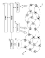
- FIG. 1 is a block diagram illustrating the configuration of the quantum computing device according to the first embodiment.
- the quantum computing device according to Embodiment 1 includes a control unit 11, a storage unit 12, a signal input unit 13, a signal reading unit 14, and a quantum unit 15.
- the control unit 11 includes, for example, a CPU (Central Processing Unit), a ROM (Read Only Memory), a RAM (Random Access Memory), and the like.
- the CPU of the control unit 11 controls various hardware operations such as the signal input unit 13 and the signal reading unit 14 by executing various programs stored in advance in the ROM or the storage unit 12.
- the RAM of the control unit 11 temporarily stores data generated during execution of various programs.
- the control part 11 may be provided with functions, such as a time measuring part which counts the elapsed time after giving a measurement start instruction
- each hardware is controlled by the control unit 11 having a CPU, ROM, RAM, and the like.
- each hardware using an FPGA (Field Programmable Gate Array), an analog circuit, or the like. The operation of the wear may be controlled.
- FPGA Field Programmable Gate Array
- the storage unit 12 includes a storage device such as an HDD (Hard Disk Drive) and stores various programs and data.
- Programs stored in the storage unit 12 include programs for controlling the operation of hardware such as the signal input unit 13 and the signal reading unit 14. Further, the data stored in the storage unit 12 is calculated by the control unit 11, data necessary for controlling the operation of hardware such as the signal input unit 13 and the signal reading unit 14, data input to the quantum unit 15, and so on. Data.
- the signal input unit 13 performs input to the quantum unit 15 in accordance with a signal input from the control unit 11. More specifically, the signal input unit 13 includes means for irradiating an electromagnetic field (pulse electromagnetic field) to the nuclear spins constituting the quantum system in the quantum unit 15, and at a timing instructed by the control unit 11. Then, an input to the quantum unit 15 is performed by irradiating an electromagnetic field corresponding to the resonance frequency of the nuclear spin constituting the quantum system. Irradiation with an electromagnetic field is performed by applying an alternating current signal to a coil (not shown) provided in the vicinity of the sample.
- an electromagnetic field pulse electromagnetic field
- the signal readout unit 14 is, for example, a magnetic resonance spectrometer, and acquires a measurement value by observing the state of the measurement spins B1 and B2 included in the quantum unit 15.
- the signal reading unit 14 outputs the acquired measurement value to the control unit 11.
- the quantum unit 15 is configured by a quantum reservoir using, for example, an ensemble of nuclear spin clusters in a solid or liquid as a quantum system.
- the input spins A1 and A2 whose spin interaction with other spins is controlled by an electromagnetic field having a first resonance frequency, and a plurality of node spins N that perform spin interaction with each other. , N,..., N, and measurement spins B1, B2 in which the spin-spin interaction with other spins is controlled by an electromagnetic field having a second resonance frequency different from the first resonance frequency.
- the spin-spin interaction includes, for example, a dipole interaction, a Fermi contact interaction, a J bond, and the like.
- the quantum computing device controls the interaction between spins that works between spins for the purpose of improving the accuracy of input, measurement, and time evolution. Specifically, control for suppressing, deforming, or erasing the interaction between spins is executed, and a signal is input to the quantum system, time evolution in the quantum system, and a signal is read from the quantum system.
- the configuration in which the quantum unit 15 includes two input spins A1 and A2 is shown, but the number of input spins is not limited to two, and may be one. Moreover, the structure containing several input spin from which resonance frequency differs may be sufficient.
- the configuration in which the quantum unit 15 includes two measurement spins B1 and B2 is shown, but the number of measurement spins is not limited to two, and may be one. Moreover, the structure containing the some measurement spin from which resonance frequency differs may be sufficient.
- the node spins N, N,..., N included in the quantum unit 15 may all have the same resonance frequency. Therefore, in the present embodiment, each of the node spins N, N,..., N need not have different resonance frequencies, and it is easy to increase the scale of the spin system.
- the signal input unit 13 irradiates an electromagnetic field to the input spins A1 and A2 or the node spins N that are adjacent to the input spins A1 and A2 and whose frequency is shifted by the interaction between the spins.
- a signal is input to the quantum unit 15.
- the signal input unit 13 appropriately controls the spin-spin interaction between the measurement spins B1 and B2 and the node spin N, which are unnecessary spin-spin interactions, by appropriately irradiating a decoupling pulse (for example, suppression or The signal is input in a state in which the interaction between the spins is controlled.
- a decoupling pulse for example, suppression or The signal is input in a state in which the interaction between the spins is controlled.
- the quantum system of the quantum unit 15 is developed over time.
- the signal input unit 13 appropriately irradiates a decoupling pulse, thereby causing an unnecessary spin-spin interaction between the input spins A1, A2 and the node spin N, and a measurement spin B1,
- the interaction between spins between B2 and the node spin N is controlled, and the quantum system is evolved over time in a state where these interactions between the spins are controlled.
- the signal reading unit 14 reads the signal from the measurement spins B1 and B2 or the node spin N adjacent to the measurement spins and whose frequency is shifted by the interaction between the spins, so that the measurement spins B1 are superposed on the state of each cudit. , B2 is observed. At this time, by appropriately irradiating a decoupling pulse, the signal is read out in a state in which the spin-spin interaction between the input spins A1 and A2 and the node spin N, which are unnecessary spin-spin interactions, is controlled.
- a cudit is a quantum information element having an arbitrary integer number of levels, and includes qubits (qubits), cuits and the like.
- a specific example is a spin having an arbitrary spin quantum number including spin 1/2.
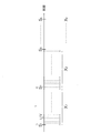
- FIG. 2 is an explanatory diagram illustrating variables related to time series processing.
- S l is a vector having k (k> L) values S m as components.
- Control unit 11 without initializing the input spin A1, A2, performs control according to the irradiation of the electromagnetic field according to an input S m for each time period t by the signal input unit 13, the state of the input spin A1, A2 Control.
- the quantum system included in the quantum unit 15 develops in time due to the spin-spin interaction between the node spins N, N,.
- the control unit 11 obtains linear weights W (VNL) that are closest to Y 1 when multiplying the measured values X 1 (vectors of VNL components) obtained from known L inputs S 1 by linear weights. Is obtained by learning.
- the linear weight W is learned based on the least square method (linear regression) so as to minimize the residual sum of squares between Y l and the linear sum of the measured values X l . This can be implemented very simply and quickly by using, for example, a pseudo inverse matrix. In addition, it is added that there are various options for determining the linear weight depending on the experimental situation.
- linear weight regularization by Ridge regression, Lasso regression, Elastic net method, or the like can be introduced as appropriate in order to prevent problems due to over-learning.
- the learning process can be performed not by badge processing but by real-time processing using a recursive least square method or a so-called FORCE learning method.
- the control unit 11 predicts the output Y l for the unknown S l using the obtained linear weight W.
- the nuclear spin cluster in the material is used as the quantum system in the quantum unit 15.
- substances having such nuclear spin clusters for example, p- terphenyl - the host molecule 2 H 13, can be formed using a single crystal sample doped about 1% p- terphenyl derivative molecules.
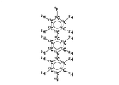
- FIG. 3A is a diagram showing the chemical structure of p- terphenyl derivative molecules
- FIG. 3B p- terphenyl - shows the chemical structure of the host molecules 2 H 13.
- 1 H, 2 H, 13 C, and 19 F have a nuclear spin
- 12 C contained in the host molecule does not have a nuclear spin.
- An inter-spin interaction that is inversely proportional to the cube of the distance works between nuclear spins as well as between different nuclei, and this quantum interaction causes complex quantum dynamics.
- a single crystal sample doped with about 1% of p-terphenyl derivative molecules has a plurality of reservoir quantum systems.
- the sample can be regarded as an ensemble of reservoir quantum systems, and all the reservoir quantum systems are independently developed in time.
- FIG. 4 is an explanatory diagram for explaining a control method of the quantum unit 15.
- the control unit 11 controls the signal input unit 13 to control unnecessary spin interaction.
- the control unit 11 outputs an electromagnetic field corresponding to the resonance frequency ⁇ 19 of 19 F. Control to irradiate from the input unit 13 is performed, and 13 C- 19 F is decoupled.
- control unit 11 signals the electromagnetic field corresponding to the resonance frequency ⁇ 2 of 2 H. Control to always irradiate from the input unit 13 is performed to decouple between 2 H- 13 C.
- the signal input unit 13 inputs a signal to the input spins A1 and A2 under the state where the unnecessary spin interaction is controlled by the electromagnetic field described above.
- the signal input unit 13 irradiates the electromagnetic field with an intensity of ⁇ pulse at a frequency of ⁇ 13 ⁇ d CH .
- ⁇ 13 is the resonance frequency of 13 C
- d CH is the interaction strength between 13 C- 1 H.
- the signal input unit 13 does not irradiate the electromagnetic field. By irradiation with this electromagnetic field, only 13 C adjacent to 1 H can be inverted according to the input.
- control unit 11 performs control for time evolution (free time evolution) of the quantum system included in the quantum unit 15.
- control unit 11 controls the signal input unit 13 to control unnecessary spin-spin interaction in the quantum unit 15, thereby causing the quantum system to evolve over time.
- the control unit 11 outputs an electromagnetic field corresponding to the resonance frequency ⁇ 1 of 1 H as a signal. Control is performed to irradiate from the input unit 13 to decouple between 1 H and 13 C.
- the control unit 11 performs control to continue irradiation of an electromagnetic field corresponding to the resonance frequency ⁇ 19 of 19 F, and 13 C- 19 Continue decoupling between F. Furthermore, since the spin-spin interaction between the 2 H spin and the other spins is unnecessary from the time of signal input to the time of signal measurement, the control unit 11 irradiates an electromagnetic field corresponding to the resonance frequency ⁇ 2 of 2 H. To continue the decoupling between 2 H and 13 C. As described above, in the quantum reservoir in the quantum unit 15, the quantum system can be developed in time only by the interaction between spins between 13 C and 13 C.
- the control unit 11 controls the signal input unit 13 and the signal reading unit 14 to read signals from the measurement spins B1 and B2 included in the quantum unit 15.
- the control unit 11 controls the signal input unit 13 to control the resonance frequency of 19 F.
- the irradiation of the electromagnetic field corresponding to ⁇ 19 is stopped, and the spin-spin interaction between 13 C- 19 F is restored.
- the control unit 11 controls the signal reading unit 14 to read a signal of ⁇ 13 ⁇ d CF from the 13 C nuclear spin.
- d CF is the interaction strength between 13 C- 19 F. Since the state of 13 C adjacent to 19 F is reflected in the phase of the signal, the control unit 11 can analyze the phase and determine the measurement value X 1 corresponding to the state.
- the control unit 11 controls the operations of the signal input unit 13 and the signal reading unit 14 to repeat the procedure related to the time evolution of the quantum system and the procedure related to signal measurement V times. Then, the control unit 11 executes a procedure related to signal input according to the same procedure as described above according to the input S 2 as the next input, and again a procedure related to time evolution of the quantum system and a procedure related to signal measurement. Repeat V times. The control unit 11 repeats these procedures k times to obtain measurement values X 1 , X 2 ,..., X kV .
- the control unit 11 performs the above-described series of procedures on L S 1 whose outputs are known, and learns the linear weight W closest to Y 1 for the obtained measurement value.
- the linear weight W can be obtained by, for example, a pseudo inverse matrix method.
- control unit 11 can obtain kV measurement values X by performing the above-described series of procedures with respect to an unknown input, and obtain an output using the learned linear weight W.
- the above-described extreme quantum learning can be applied to machine learning such as character recognition that does not require time series analysis.
- FIG. 5 is a flowchart showing a procedure of processing executed by the control unit 11.
- the control unit 11 controls the signal input unit 13 to input a signal corresponding to the input S j whose output is known to the quantum unit 15 (step S103). At this time, the control unit 11 irradiates the sample of the quantum unit 15 from the signal input unit 13 with an electromagnetic field having a resonance frequency of the corresponding spin in order to decouple unnecessary spin interactions such as the output spins B1 and B2.
- the control unit 11 applies the electromagnetic field through the signal input unit 13 to the input spins A1 and A2 or the node spin N that is adjacent to the input spins A1 and A2 and whose frequency is shifted by the interaction. , A signal corresponding to the input S j is input. Note that when the input S j is 0, the control unit 11 does not irradiate the electromagnetic field.
- control unit 11 develops the quantum system in the quantum unit 15 over time (step S104).
- control unit 11 quantizes an electromagnetic field having a resonance frequency of the corresponding spin from the signal input unit 13 in order to decouple unnecessary spin-to-spin interactions such as the input spins A1 and A2 and the output spins B1 and B2.
- the sample of unit 15 is irradiated.
- the quantum system in the quantum unit 15 develops in time in a state where unnecessary spin interaction is decoupled.
- control unit 11 determines whether or not time t / V ⁇ i has elapsed since the timer was reset (step S105). When the time t / V ⁇ i has not elapsed (S105: NO), the control unit 11 returns the process to step S104.
- the control unit 11 When it is determined that the time t / V ⁇ i has elapsed since the timer was reset (S105: YES), the control unit 11 reads the state from the measurement spins B1 and B2 of the quantum unit 15 and performs signal measurement (step) S106). At this time, the control unit 11 irradiates the sample of the quantum unit 15 from the signal input unit 13 with an electromagnetic field having a resonance frequency of the corresponding spin in order to decouple unnecessary spin interactions such as the input spins A1 and A2. Let Further, the control unit 11 reads the states of the measurement spins B1 and B2 through the signal reading unit 14.
- control unit 11 determines whether i ⁇ V (step S107).
- V is the number of divisions of the measurement time.
- the control unit 11 increments the value of the counter i by 1 (step S108) and returns the process to step S104.
- the control unit 11 acquires a measured value Xj for the input Sj based on the signal measured at every t / V (step S109).
- control unit 11 determines whether j ⁇ k is satisfied (step S110).
- k is the number of input S j.
- the control unit 11 resets the value of the counter i to 1 and increases the value of the counter j by 1 (step S111), and the process is performed in step S102.
- the control unit 11 determines a weight W (step S112).
- L is the number of measurement values X j whose input / output relationship is known.
- the linear weight W can be obtained by, for example, a pseudo inverse matrix method.
- control unit 11 predicts an output Y l for an unknown input S j (L ⁇ j ⁇ k) using the determined linear weight W (step S113).
- a quantum system can be constructed using the spin-spin interaction of several types of spins such as the input spins A1 and A2, the node spin N, and the output spins B1 and B2.
- spins A1 and A2 the input spins A1 and A2
- node spin N the node spin N
- output spins B1 and B2 the output spins B1 and B2.
- initialization for the input spins A1 and A2 is unnecessary, and output can be predicted by extreme quantum learning.
- FIG. 6 is a block diagram illustrating the configuration of the quantum computing device according to the second embodiment.
- the quantum computing device according to the second embodiment includes a cooling unit 20 in addition to the control unit 11, the storage unit 12, the signal input unit 13, the signal reading unit 14, and the quantum unit 15. Since the configurations of the control unit 11, the storage unit 12, the signal input unit 13, the signal reading unit 14, and the quantum unit 15 are the same as those in the first embodiment, description thereof is omitted.
- the cooling unit 20 cools the cooling system 21 including the polarization source R0, the cooling spins R1, R2, and the refrigerant spins R, R, ..., R under the control of the control unit 11.
- the polarization source R0 as will be described later, pentacene having photoexcited triplet electrons can be used. Further, instead of a configuration in which initialization is performed using highly polarized electrons (photoexcited triplet), spin cooling may be performed using electron spin lattice relaxation at an extremely low temperature.
- the cooling spins R1 and R2 are spins that can always be initialized by operating the cooling unit 20, and are specifically 1 H spins located in the vicinity of the polarization source R0.
- Such 1 H spins host molecules cooling source R0 is doped (for example, described below p- terphenyl - 2 H 13 molecules) are provided.
- the refrigerant spins R, R,..., R take a distance such that the polarization source R0 is directly coupled to the input spins A1, A2 and the node spins N, N,. Necessary existence.
- the refrigerant spins R, R,..., R are specifically 1 H spins located around the cooling spins R1, R2. Similar to the cooling spins R1 and R2, the 1 H spin is provided in the host molecule.
- the refrigerant spins R, R,..., R are unnecessary, and the cooling spins R1, R2 are input spins.
- A1 and A2 may be directly coupled.
- a single crystal sample doped with about 1% of a p-terphenyl derivative molecule as a reservoir molecule and about 0.05 mol% of pentacene as a polarization source molecule can be used with respect to the host molecule.
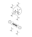
- FIG. 7 is a diagram showing the chemical structure of a single crystal sample in which reservoir molecules and polarized source molecules are doped into host molecules.
- the molecule surrounded by a broken line is a reservoir molecule.
- This reservoir molecule is a p-terphenyl derivative molecule having 1 H, 2 H, 13 C, and 19 F nuclear spins.
- 13 no nuclear spin of C p-terphenyl - 2 H 13 molecule is present.
- initialization refers to increasing the polarization rate from about one-hundredths of a thousand to nearly 1.0 by some method.
- high polarization of 1 H spin is realized by using pentacene having photoexcited triplet electrons as a polarization source molecule.
- triplet DNP Dynamic Nuclear Polarization
- photoexcited electron spin is initialized by irradiation with a laser pulse.
- nearby 1 H spins are initialized by dynamic nuclear polarization by microwave irradiation.
- the polarized state is, 1 H spins in the sample, specifically diffuse into 1 H spin of the 1 H spin, and reservoir molecules of the 1 H spin, the host molecules of pentacene.
- 1 H spin of the entire sample is gradually increased in polarization and stabilized to a constant high polarization rate.
- FIG. 8 is an explanatory diagram for explaining a control method of the quantum unit 15.
- the control unit 11 determines the resonance frequency ⁇ 2 of 2 H.
- the signal input unit 13 is constantly irradiated with an electromagnetic field corresponding to 1 to decouple between 2 H and 13 C.
- the control unit 11 it is assumed that the control unit 11 always performs triplet DNP by controlling the cooling unit 20, and all 1 H spins in the sample are initialized by the triplet DNP.
- the control unit 11 performs the 19 electromagnetic field corresponding to the resonance frequency omega 19 of F, and control for irradiating an electromagnetic field corresponding to the resonance frequency omega 2 of 2 H from the signal input unit 13, 13 C-19 Decouple between F and between 2 H- 13 C.
- the control unit 11 irradiates the electromagnetic field with an intensity of ⁇ pulse at a frequency of ⁇ 13 ⁇ d CH .
- the 1 H spin is in a state of
- the control unit 11 keeps the 1 H spin at
- the control unit 11 places a swap gate between the 1 H spin and the 13 C spin adjacent thereto. Specifically, the control unit 11 applies a CNOT from 13 C to 1 H, applying a CNOT then from 1 H to 13 C. Then, CNOT is applied from 13 C to 1 H. More specifically, first, a line selective inversion pulse is applied to ⁇ 1 + d CH, and then a line selective inversion pulse is applied to ⁇ 13 + d CH . Then, a line selective inversion pulse is applied to ⁇ 1 + d CH . As a result, the state of 13 C spin adjacent to 1 H can be made to correspond to the value of the input S 1 . Thereafter, the state of 1 H spin is quickly initialized because triplet DNP is continuously performed.
- control unit 11 performs control for causing the quantum system included in the quantum unit 15 to develop in time (free time evolution). At this time, the control unit 11 controls the signal input unit 13 to control unnecessary spin-spin interaction in the quantum unit 15, thereby causing the quantum system to evolve over time.
- control unit 11 controls the signal input unit 13 and the signal reading unit 14 to read signals from the measurement spins B1 and B2 included in the quantum unit 15. At this time, the control unit 11, the irradiation of an electromagnetic field corresponding to the resonance frequency omega 19 of 19 F controls the signal input unit 13 is stopped, revive spin interactions between 13 C-19 F. In addition, the control unit 11 controls the signal reading unit 14 to read a signal of ⁇ 13 ⁇ d CF from the 13 C nuclear spin. Since the state of 13 C adjacent to 19 F is reflected in the phase of the signal, the control unit 11 can analyze the phase and determine the measurement value X 1 corresponding to the state.
- the control unit 11 controls the operations of the signal input unit 13 and the signal reading unit 14 to repeat the procedure related to the time evolution of the quantum system and the procedure related to signal measurement V times. Then, the control unit 11 executes a procedure related to signal input in accordance with the input S 2 according to the same procedure as described above, and repeats a procedure related to time evolution of the quantum system and a procedure related to signal measurement V times again. . The control unit 11 repeats these procedures k times to obtain X 1 , X 2 ,..., X kV .
- the control unit 11 performs the above-described series of procedures on L S 1 whose outputs are known, and learns the linear weight W closest to Y 1 for the obtained measurement value.
- the linear weight W can be obtained by, for example, a pseudo inverse matrix method.
- control unit 11 can obtain kV measurement values X by performing the above-described series of procedures with respect to an unknown input, and obtain an output using the learned linear weight W.
- a method using triplet DNP has been described as an initialization method.
- DNP using thermal equilibrium electrons at a very low temperature as a polarization source may be used.
- the polarization source molecule described above can be implemented by, for example, a host molecule single crystal in which the BDPA radical molecule described later is doped, and the reservoir molecule is doped with the p-terphenyl derivative described above.
- it can be implemented by a host molecule single crystal doped with molecules in which the polarization source portion and the reservoir portion are modified.
- the present invention can also be implemented by a single crystal configuration in which a polarization source molecule (pentacene) doped with a reservoir molecule (p-terphenyl derivative) is used as a host.
- FIG. 9 is a diagram illustrating a second implementation example of the quantum unit 15.
- the reservoir molecule 1-alanine - 13 C, 15 N the host molecule 1-alanine - 2 H 7, 13 C, the Henkyokugen molecules are also possible sample of pentacene.
- the quantum dynamics are borne by the 1 H spin in the 1 -alanine molecule.
- Input and measurement are performed by 13 C spin and 15 N spin. Using the difference in chemical shift, multiple inputs and measurements are possible.
- FIG. 10 is a diagram illustrating a third implementation example of the quantum unit 15. Be a single crystal - (2 H 14 p-terphenyl), Henkyokugen site as shown in Figure 10 the host molecules molecules (pentacene group) and reservoir portion (p- terphenyl derivative) is modified doped It is possible to implement the extreme quantum learning described in the first embodiment and the quantum reservoir calculation described in the second embodiment.
- FIG. 11 is a diagram illustrating a fourth implementation example of the quantum unit 15.
- FIG. 11 shows a mounting example using an electron spin system.
- the single crystal of the host molecule (benzene) doped with the reservoir molecule (TEMPO radical oligomer) and the polarization source molecule (BDPA radical: electron spin is represented by E B ) has been described in the first embodiment.
- Extreme quantum learning and the quantum reservoir calculation described in the second embodiment can be implemented.
- the electron spin of the TEMPO group at the end of the oligomer is the spin responsible for input and measurement, and the electron spin of the other TEMPO group is responsible for the quantum dynamics of the reservoir.
- the electron spin of BDPA is initialized by coupling with the lattice.
- FIG. 12 is a diagram illustrating a fifth implementation example of the quantum unit 15.
- Reservoir molecules as shown in FIG. 12 (TEMPO oligomer: electron spin is indicated by E T) Extreme Quantum described the Henkyokugen molecules doped (BDPA) in the first embodiment be either single crystal single crystal hosted Learning and the quantum reservoir calculation described in the second embodiment can be implemented.
- the electron spin of the TEMPO group at the end of the oligomer is the spin responsible for input and measurement, and the electron spin of the other TEMPO group is responsible for the quantum dynamics of the reservoir.
- the electron spin of BDPA is initialized by coupling with the lattice.
- the quantum reservoir may be controlled such that the electron spin of the TEMPO oligomer molecule is responsible for input and measurement, and the 19 F spin of the TEMPO oligomer molecule is responsible for the quantum dynamics of the reservoir.
- the present invention makes it possible to solve various problems surrounding modern society. Almost all applications where conventional reservoir calculations are said to have better performance than the von Neumann type can perform even better in quantum reservoir calculations.
- An example of such an application is chaos time series prediction, and stock price prediction is considered as the highest market value.
- it can be applied to prediction of earthquake fluctuation, analysis of biological signals, autonomous control of robots, nonlinear compensation of wireless communication systems, and the like. It can also be used for machine learning and is expected to be applied to image recognition, voice recognition, artificial intelligence, and the like.
- Control unit time development control unit, weight determination unit
- Storage Unit Signal Input Unit 14
- Signal Reading Unit Quantum Unit (Quantum Reservoir)
- Cooling unit initialization unit
- Cooling system A1, A2 Input spin B1, B2 Measurement spin N Node spin R0 Polarization source R1, R2 Cooling spin R Refrigerant spin
Landscapes
- Engineering & Computer Science (AREA)
- Theoretical Computer Science (AREA)
- Physics & Mathematics (AREA)
- General Physics & Mathematics (AREA)
- Chemical & Material Sciences (AREA)
- Mathematical Physics (AREA)
- General Engineering & Computer Science (AREA)
- Computing Systems (AREA)
- Nanotechnology (AREA)
- Software Systems (AREA)
- Computational Mathematics (AREA)
- Mathematical Analysis (AREA)
- Mathematical Optimization (AREA)
- Pure & Applied Mathematics (AREA)
- Crystallography & Structural Chemistry (AREA)
- Optical Modulation, Optical Deflection, Nonlinear Optics, Optical Demodulation, Optical Logic Elements (AREA)
- Hall/Mr Elements (AREA)
Abstract
量子計算装置及び量子計算方法の提供。 物質中の核スピン又は電子スピンの状態を表すキューディットを複数含んだ量子系により構成されており、量子系には、入力スピン、複数のノードスピン、及び測定スピンが含まれる量子レザバーと、第2電磁場を照射することにより測定スピンとノードスピンとの間のスピン間相互作用を制御し、入力スピンを通じて信号を入力する信号入力部と、ノードスピン間のスピン間相互作用により量子系を時間発展させる時間発展制御部と、第1電磁場の照射を維持して第2電磁場の照射を停止することにより、入力スピンと他のスピンとの間のスピン間相互作用を制御した状態にて、測定スピンとノードスピンとの間のスピン間相互作用を復活させ、測定スピンを通じて信号を読み出す信号読出部とを備える。
Description
本発明は、量子計算装置及び量子計算方法に関する。
従来の半導体型フォンノイマンアーキテクチャ計算機の発展が終焉を迎えるにあたり、これに代わる新しいアーキテクチャでの計算能力の持続可能な発展が求められている。ディジタル量子計算機はその最有力候補の一つとして世界中で開発競争が繰り広げられている。ディジタル量子計算機とは、フォンノイマン型計算で用いられるビット素子の部分を、量子力学的重ね合わせを許す量子ビット素子に置き換えたものである。ディジタル量子計算機は、例えば素因数分解が従来計算機よりも桁数に対して指数関数的に早く解けることが示されている(例えば、非特許文献1を参照)。
M.A. Nielsen & I.L. Chuang, "Quantum Computation and Quantum Information", Cambridge Univ. Press (2012)
素因数分解で既存の計算機を超えるには外部ノイズのない理想的な状況でも1000量子ビット以上を扱う必要がある(例えば、特許文献1を参照)。外部ノイズから守りながら正確に制御するためには、100万量子ビット以上用意して冗長度を持たせる量子誤り訂正技術が必要不可欠となる。
従来のアンサンブルスピン型量子計算では、全てのスピンを個別に自在操作するために、共鳴周波数を全てのスピンで異ならせる必要があり、上述したような多数の量子ビットからなる量子系を実現することは困難であった。
本発明は、斯かる事情に鑑みてなされたものであり、数種類のスピン間相互作用を利用して量子系を構築できる量子計算装置及び量子計算方法を提供することを目的とする。
本発明の一態様に係る量子計算装置は、物質中の核スピン又は電子スピンの状態を表すキューディットを複数含んだ量子系により構成された量子レザバーを備え、前記量子系は、第1共鳴周波数を有する第1電磁場によって他のスピンとの間のスピン間相互作用が制御される入力スピンと、互いにスピン間相互作用が働く複数のノードスピンと、前記第1共鳴周波数とは異なる第2共鳴周波数を有する第2電磁場によって他のスピンとの間のスピン間相互作用が制御される測定スピンとを含み、前記第2電磁場を照射することにより前記測定スピンと前記ノードスピンとの間のスピン間相互作用を制御し、該スピン間相互作用を制御した状態にて、前記入力スピンを通じて信号を入力する信号入力部と、前記第1及び第2電磁場を照射することにより前記入力スピンと前記ノードスピンとの間のスピン間相互作用、及び前記測定スピンと前記ノードスピンとの間のスピン間相互作用を制御し、前記ノードスピン間のスピン間相互作用により前記量子系を時間発展させる時間発展制御部と、前記第1電磁場の照射を維持して前記第2電磁場の照射を停止することにより、前記入力スピンと他のスピンとの間のスピン間相互作用を制御した状態にて、前記測定スピンと前記ノードスピンとの間のスピン間相互作用を復活させ、前記測定スピンを通じて信号を読み出す信号読出部とを更に備える。
本発明の一態様に係る量子計算方法は、物質中の核スピン又は電子スピンの状態を表すキューディットを複数含んだ量子系を用いて量子計算を行う量子計算方法であって、前記量子系に含まれる測定スピンと複数のノードスピンとの間のスピン間相互作用を制御すべく、第2共鳴周波数を有する第2電磁場を照射し、前記スピン間相互作用を制御した状態にて、前記量子系に含まれる入力スピンを通じて信号を入力し、前記スピン間相互作用を制御した状態にて、更に前記入力スピンと前記複数のノードスピンとの間のスピン間相互作用を制御すべく、前記第2共鳴周波数とは異なる第1共鳴周波数を有する第1電磁場を照射し、前記入力スピンと前記複数のノードスピンとの間のスピン間相互作用、及び前記測定スピンと前記複数のノードスピンとの間のスピン間相互作用を制御した状態にて、前記ノードスピン間のスピン間相互作用により前記量子系を時間発展させ、前記第1電磁場の照射を維持して前記第2電磁場の照射を停止し、前記入力スピンと前記複数のノードスピンとの間のスピン間相互作用を制御し、前記測定スピンと前記ノードスピンとの間のスピン間相互作用を復活させた状態にて、前記測定スピンを通じて前記量子系から信号を読み出す。
本発明の一側面によれば、数種類のスピン間相互作用を利用して量子系を構築することができる。
以下、本発明をその実施の形態を示す図面に基づいて具体的に説明する。
(実施の形態1)
図1は実施の形態1に係る量子計算装置の構成を説明するブロック図である。実施の形態1に係る量子計算装置は、制御部11、記憶部12、信号入力部13、信号読出部14、及び量子部15を備える。
(実施の形態1)
図1は実施の形態1に係る量子計算装置の構成を説明するブロック図である。実施の形態1に係る量子計算装置は、制御部11、記憶部12、信号入力部13、信号読出部14、及び量子部15を備える。
制御部11は、例えば、CPU(Central Processing Unit)、ROM(Read Only Memory)、RAM(Random Access Memory)等を備える。制御部11のCPUは、ROM又は記憶部12に予め記憶された各種プログラムを実行することにより、信号入力部13、信号読出部14等のハードウェアの動作を制御する。制御部11のRAMは、各種プログラムの実行中に生成されるデータ等を一時的に記憶する。また、制御部11は、計測開始指示を与えてから計測終了指示を与えるまでの経過時間を計時する計時部、及び数をカウントする計数部等の機能を備えていてもよい。
なお、本実施の形態では、CPU、ROM、RAM等を備えた制御部11により各ハードウェアの動作を制御する構成としたが、FPGA(Field Programmable Gate Array)、アナログ回路等を用いて各ハードウェアの動作を制御してもよい。
記憶部12は、HDD(Hard Disk Drive)などの記憶装置を備え、各種プログラム及びデータを記憶する。記憶部12が記憶するプログラムには、信号入力部13、信号読出部14等のハードウェアの動作を制御するためのプログラム等が含まれる。また、記憶部12が記憶するデータには、信号入力部13、信号読出部14等のハードウェアの動作を制御するために必要なデータ、量子部15へ入力するデータ、制御部11により演算されたデータ等が含まれる。
信号入力部13は、制御部11から入力される信号に応じて、量子部15への入力を行う。より具体的には、信号入力部13は、量子部15内の量子系を構成する核スピンに対して電磁場(パルス電磁場)を照射する手段を備えており、制御部11から指示されるタイミングにて、量子系を構成する核スピンの共鳴周波数等に対応した電磁場を照射することにより、量子部15への入力を行う。なお、電磁場の照射は、試料の近傍に設けられたコイル(不図示)に対して交流電流信号を印加することにより行われる。
信号読出部14は、例えば磁気共鳴分光計であり、量子部15が備える測定スピンB1,B2の状態の観測することにより、測定値を取得する。信号読出部14は、取得した測定値を制御部11へ出力する。
量子部15は、例えば固体又は液体中の核スピンクラスターのアンサンブルを量子系とした量子レザバーにより構成されている。本実施の形態に係る量子レザバーには、第1共鳴周波数を有する電磁場により他のスピンとのスピン間相互作用が制御される入力スピンA1,A2、互いにスピン間相互作用を行う複数のノードスピンN,N,…,N、及び第1共鳴周波数とは異なる第2共鳴周波数を有する電磁場により他のスピンとのスピン間相互作用が制御される測定スピンB1,B2が含まれている。ここで、スピン間相互作用には、例えば双極子相互作用、フェルミ接触相互作用、J結合などが含まれる。本実施の形態に係る量子計算装置は、入力や測定、時間発展を高精度化する目的でスピン間に働くスピン間相互作用を制御する。具体的には、スピン間相互作用を抑制、変形、若しくは消去する制御を実行し、量子系への信号の入力、量子系における時間発展、及び量子系からの信号の読み出しを行う。
なお、図1の例では、量子部15が2つの入力スピンA1,A2を備える構成を示したが、入力スピンの数は2つに限定されるものではなく、1つであってもよい。また、共鳴周波数が異なる複数の入力スピンを含む構成であってもよい。
また、図1の例では、量子部15が2つの測定スピンB1,B2を備える構成を示したが、測定スピンの数は2つに限定されるものではなく、1つであってもよい。また、共鳴周波数が異なる複数の測定スピンを含む構成であってもよい。
量子部15が備えるノードスピンN,N,…,Nについては、全て同一の共鳴周波数であってもよい。よって、本実施の形態では、ノードスピンN,N,…,Nのそれぞれが異なる共鳴周波数を有している必要はなく、スピン系を大規模化することが容易となる。
本実施の形態では、信号入力部13は、入力スピンA1,A2、又は入力スピンA1,A2と隣接してスピン間相互作用により周波数がシフトしたノードスピンNに対して、電磁場を照射することにより量子部15への信号入力を行う。このとき、信号入力部13は、適宜デカップリングパルスを照射することにより、不要なスピン間相互作用である測定スピンB1,B2とノードスピンNとの間のスピン間相互作用を制御(例えば抑制又は消去)し、当該スピン間相互作用を制御した状態にて信号入力を行う。
また、本実施の形態では、量子部15への信号入力の後、量子部15の量子系を時間発展させる。このとき、信号入力部13は、適宜デカップリングパルスを照射することにより、不要なスピン間相互作用である入力スピンA1,A2とノードスピンNとの間のスピン間相互作用、及び測定スピンB1,B2とノードスピンNとの間のスピン間相互作用を制御し、これらのスピン間相互作用を制御した状態にて量子系を時間発展させる。
信号読出部14は、測定スピンB1,B2、または測定スピンと隣接してスピン間相互作用により周波数がシフトしたノードスピンNから信号を読み出すことにより、各キューディットの状態の重ね合わせとして測定スピンB1,B2に現れるスピンの状態を観測する。このとき、適宜デカップリングパルスを照射することにより、不要なスピン間相互作用である入力スピンA1,A2とノードスピンNとの間のスピン間相互作用を制御した状態にて、信号の読み出しを行う。
ここで、キューディットとは、任意の整数個の準位を持つ量子情報素子であり、量子ビット(キュービット)、キュートリットなどがこれに含まれる。具体例としては、スピン1/2を含む任意のスピン量子数のスピンが挙げられる。
ここで、キューディットとは、任意の整数個の準位を持つ量子情報素子であり、量子ビット(キュービット)、キュートリットなどがこれに含まれる。具体例としては、スピン1/2を含む任意のスピン量子数のスピンが挙げられる。
以下、計算手順の概略について説明する。
図2は時系列処理に関連する変数を説明する説明図である。実施の形態1では、ある関数Yl =F(Sl )について、L個の既知の入出力関係を用いて学習を行うエクストリーム量子学習を実現する。ここで、Sl は、k個(k>L)の値Sm を成分にもつベクトルである。制御部11は、入力スピンA1,A2の初期化を行わずに、時間間隔tごとに入力Sm に従って電磁場の照射に係る制御を信号入力部13にて行い、入力スピンA1,A2の状態を制御する。量子部15が備える量子系は、ノードスピンN,N,…,N間のスピン間相互作用によって時間発展する。信号読出部14は、時間間隔t/VごとにN個(本実施の形態ではN=2)の測定スピンB1,B2の状態を測定する。制御部11は、既知のL個の入力Sl から得られた測定値Xl (VNL個の成分からなるベクトル)に線形重みを乗算したときに最もYl に近くなる線形重みW(VNL個の成分からなるベクトル)を学習により求める。具体的には、Yl と測定値Xl の線形和との間の残差二乗和を最小にするように、最小二乗法(線形回帰)に基づいて、線形重みWを学習する。これは、例えば、疑似逆行列などを用いることできわめて簡易にかつ素早く実装することができる。また、線形重みの決定法には、実験状況に応じて、様々な選択肢が存在することを付言しておく。例えば、レザバーにおける計算素子数が多すぎる場合、過学習による問題を防ぐために、Ridge回帰、Lasso回帰、ならびにElastic netの手法などによる線形重みの正則化を適宜導入することができる。あるいは、再帰的最小二乗法やいわゆるFORCE学習法などを用いて、学習過程をバッジ処理でなく、リアルタイム処理で行うことも可能である。制御部11は、求めた線形重みWを用いて未知のSl に対する出力Yl を予測する。
図2は時系列処理に関連する変数を説明する説明図である。実施の形態1では、ある関数Yl =F(Sl )について、L個の既知の入出力関係を用いて学習を行うエクストリーム量子学習を実現する。ここで、Sl は、k個(k>L)の値Sm を成分にもつベクトルである。制御部11は、入力スピンA1,A2の初期化を行わずに、時間間隔tごとに入力Sm に従って電磁場の照射に係る制御を信号入力部13にて行い、入力スピンA1,A2の状態を制御する。量子部15が備える量子系は、ノードスピンN,N,…,N間のスピン間相互作用によって時間発展する。信号読出部14は、時間間隔t/VごとにN個(本実施の形態ではN=2)の測定スピンB1,B2の状態を測定する。制御部11は、既知のL個の入力Sl から得られた測定値Xl (VNL個の成分からなるベクトル)に線形重みを乗算したときに最もYl に近くなる線形重みW(VNL個の成分からなるベクトル)を学習により求める。具体的には、Yl と測定値Xl の線形和との間の残差二乗和を最小にするように、最小二乗法(線形回帰)に基づいて、線形重みWを学習する。これは、例えば、疑似逆行列などを用いることできわめて簡易にかつ素早く実装することができる。また、線形重みの決定法には、実験状況に応じて、様々な選択肢が存在することを付言しておく。例えば、レザバーにおける計算素子数が多すぎる場合、過学習による問題を防ぐために、Ridge回帰、Lasso回帰、ならびにElastic netの手法などによる線形重みの正則化を適宜導入することができる。あるいは、再帰的最小二乗法やいわゆるFORCE学習法などを用いて、学習過程をバッジ処理でなく、リアルタイム処理で行うことも可能である。制御部11は、求めた線形重みWを用いて未知のSl に対する出力Yl を予測する。
本実施の形態では、計算手続きの途中で初期化を行う必要がないため、より容易に実装することが可能となる。また、レーザスピン系がわずかに偏極されているだけでも、その量子ダイナミクスは、古典計算機ではシミュレートできない程に複雑になることが証明されている。
次に、量子部15の実装例について説明する。
本実施の形態では、物質中の核スピンクラスターを量子部15における量子系として用いる。このような核スピンクラスターを有する物質として、例えば、p-ターフェニル-2 H13のホスト分子に対して、p-ターフェニル誘導体分子を1%程度ドープした単結晶試料を用いることができる。
本実施の形態では、物質中の核スピンクラスターを量子部15における量子系として用いる。このような核スピンクラスターを有する物質として、例えば、p-ターフェニル-2 H13のホスト分子に対して、p-ターフェニル誘導体分子を1%程度ドープした単結晶試料を用いることができる。
図3Aはp-ターフェニル誘導体分子の化学構造を示す図であり、図3Bはp-ターフェニル-2 H13のホスト分子の化学構造を示す図である。試料中では、1 H、2 H、13C、19Fが核スピンを有しており、ホスト分子に含まれる12Cは核スピンを有していない。核スピン間には、異種核間のみならず同種核間にも距離の三乗に反比例するスピン間相互作用が働いており、このスピン間相互作用によって複雑な量子ダイナミクスが引き起こされる。p-ターフェニル誘導体分子が1%程度ドープされた単結晶試料には、レザバー量子系が複数個存在する。ある1つのp-ターフェニル誘導体分子のキューディットと、別のp-ターフェニル誘導体分子のキューディットとは十分に距離が離れているため、これらの間の相互作用は無視することができる。よって、試料は、レザバー量子系のアンサンブルとみなすことができ、全てのレザバー量子系はそれぞれ独立して時間発展する。
図4は量子部15の制御手法を説明する説明図である。制御部11は、量子部15の入力スピンA1,A2に対して信号入力を行う場合、信号入力部13を制御して、不要なスピン間相互作用を制御する。図3Aに示すp-ターフェニル誘導体分子において、信号入力時には13C-19F間のスピン間相互作用が不要であるから、制御部11は、19Fの共鳴周波数ω19 に相当する電磁場を信号入力部13より照射させる制御を行い、13C-19F間をデカップリングする。また、信号入力時から信号測定時に至るまで2 Hスピンと他のスピンとの間のスピン間相互作用は不要であるから、制御部11は、2 Hの共鳴周波数ω2に相当する電磁場を信号入力部13より常時照射させる制御を行い、2 H-13C間をデカップリングする。
上述した電磁場により不要なスピン間相互作用を制御した状態下で、信号入力部13は、入力スピンA1,A2への信号入力を行う。例えば、入力S1 が1の場合、信号入力部13は、ω13±dCHとなる周波数でπパルスとなる強度にて電磁場を照射する。ここで、ω13は、13Cの共鳴周波数であり、dCHは、13C-1 H間の相互作用強度である。入力S1 が0の場合、信号入力部13は、上記電磁場の照射を行わない。この電磁場の照射により、1 Hに隣接する13Cのみを入力に応じて反転させることができる。
次いで、制御部11は、量子部15が備える量子系を時間発展(自由時間発展)させるための制御を行う。このとき、制御部11は、信号入力部13を制御して、量子部15における不要なスピン間相互作用を制御することにより、量子系を時間発展させる。図3Aに示すp-ターフェニル誘導体分子において、時間発展時には1 H-13C間のスピン間相互作用が不要であるから、制御部11は、1 Hの共鳴周波数ω1に相当する電磁場を信号入力部13より照射させる制御を行い、1 H-13 C間をデカップリングする。また、時間発展時には13C-19F間のスピン間相互作用が不要であるから、制御部11は、19Fの共鳴周波数ω19 に相当する電磁場の照射を継続させる制御を行い、13C-19F間のデカップリングを継続する。更に、信号入力時から信号測定時に至るまで2 Hスピンと他のスピンとの間のスピン間相互作用は不要であるから、制御部11は、2 Hの共鳴周波数ω2に相当する電磁場の照射を継続させる制御を行い、2 H-13C間をデカップリングを継続する。以上により、量子部15における量子レザバーでは、13C-13C間のスピン間相互作用だけで量子系を時間発展させることができる。
次いで、制御部11は、信号入力部13及び信号読出部14を制御して、量子部15が備える測定スピンB1,B2から信号の読み出しを行う。図3Aに示すp-ターフェニル誘導体分子において、信号読出時には、13C-19F間のスピン間相互作用を利用するので、制御部11は、信号入力部13を制御して19Fの共鳴周波数ω19に相当する電磁場の照射を停止させ、13C-19F間のスピン間相互作用を復活させる。また、制御部11は、信号読出部14を制御して、13Cの核スピンからω13±dCFの信号を読み出す。ここで、dCFは、13C-19F間の相互作用強度である。19Fに隣接する13Cの状態が信号の位相に反映されるため、制御部11は、位相を解析して状態に対応する測定値X1 を決定することができる。
制御部11は、信号入力部13及び信号読出部14の動作を制御することにより、量子系の時間発展に係る手続きと、信号測定に係る手続きとをV回繰り返す。そして、制御部11は、次の入力である入力S2 に応じて、信号入力に係る手続きを上述と同様の手順により実行し、再び量子系の時間発展に係る手続きと、信号測定に係る手続きとをV回繰り返す。制御部11は、これらの手続きをk回繰り返し、測定値X1 ,X2 ,…,XkVを得る。
制御部11は、出力が既知のL個のSl に対して、上記一連の手続きを行い、得られた測定値に対してYl に最も近くなる線形重みWを学習する。線形重みWは、例えば疑似逆行列法により求めることができる。
また、制御部11は、未知の入力に対し、上記一連の手続きを行うことによりkV個の測定値Xを取得し、学習した線形重みWを用いて出力を求めることができるようになる。上述したエクストリーム量子学習は、時系列解析が不要な文字認識などの機械学習に適用することができる。
図5は制御部11が実行する処理の手順を示すフローチャートである。制御部11は、カウンタの値を初期値(i=1,j=1)に設定すると共に(ステップS101)、タイマをリセットして(ステップS102)、以下の処理を実行する。
まず、制御部11は、信号入力部13を制御することにより、出力が既知である入力Sj に対応した信号を量子部15に入力する(ステップS103)。このとき、制御部11は、出力スピンB1,B2等の不要なスピン間相互作用をデカップリングするために、対応するスピンの共鳴周波数を有する電磁場を信号入力部13から量子部15の試料に照射させる。また、制御部11は、入力Sj が1の場合、入力スピンA1,A2、または入力スピンA1,A2と隣接して相互作用により周波数がシフトしたノードスピンNに対し、信号入力部13を通じて電磁場を照射することで入力Sj に応じた信号を入力する。なお、制御部11は、入力Sj が0の場合、電磁場の照射を行わない。
次いで、制御部11は、量子部15における量子系を時間発展させる(ステップS104)。このとき、制御部11は、入力スピンA1,A2及び出力スピンB1,B2等の不要なスピン間相互作用をデカップリングするために、対応するスピンの共鳴周波数を有する電磁場を信号入力部13から量子部15の試料に照射させる。量子部15における量子系は、不要なスピン間相互作用がデカップリングした状態にて時間発展する。
次いで、制御部11は、タイマをリセットしてから時間t/V×iが経過したか否かを判断する(ステップS105)。時間t/V×iが経過していない場合(S105:NO)、制御部11は、処理をステップS104へ戻す。
タイマをリセットしてから時間t/V×iが経過したと判断した場合(S105:YES)、制御部11は、量子部15の測定スピンB1,B2から状態を読み出し、信号測定を行う(ステップS106)。このとき、制御部11は、入力スピンA1,A2等の不要なスピン間相互作用をデカップリングするために、対応するスピンの共鳴周波数を有する電磁場を信号入力部13から量子部15の試料に照射させる。また、制御部11は、測定スピンB1,B2の状態を信号読出部14を通じて読み出す。
次いで、制御部11は、i≧Vであるか否かを判断する(ステップS107)。ここで、Vは測定時間の分割数である。カウンタiの値がV未満の場合(S107:NO)、制御部11は、カウンタiの値を1だけ増加させて(ステップS108)、処理をステップS104へ戻す。
カウンタiの値がV以上であると判断した場合(S107:YES)、制御部11は、t/Vごとに測定した信号に基づき、入力Sj に対する測定値Xj を取得する(ステップS109)。
次いで、制御部11は、j≧kであるか否かを判断する(ステップS110)。ここで、kは入力Sj の個数である。カウンタjの値がk未満の場合(S110:NO)、制御部11は、カウンタiの値を1にリセットすると共に、カウンタjの値を1だけ増加させて(ステップS111)、処理をステップS102へ戻す。
カウンタjの値がk以上であると判断した場合(S110:YES)、制御部11は、得られた測定値X1 ,X2 ,…,XL を用いて、重みWを決定する(ステップS112)。ここで、Lは、入出力の関係が既知である測定値Xj の個数である。制御部11は、得られた測定値X1 ,X2 ,…,Xj に対して既知のYl に最も近くなるような線形重みWを学習する。線形重みWは、例えば疑似逆行列法により求めることができる。
次いで、制御部11は、決定した線形重みWを用いて、未知の入力Sj (L≦j≦k)に対する出力Yl を予測する(ステップS113)。
以上のように、実施の形態1では、入力スピンA1,A2、ノードスピンN、出力スピンB1,B2といった数種類のスピンのスピン間相互作用を利用して量子系を構築することができる。文字認識等の時系列解析が不要な分野については、入力スピンA1,A2に対する初期化が不要であり、エクストリーム量子学習により、出力を予測することが可能となる。
(実施の形態2)
実施の形態2では、入力スピンA1,A2に信号を入力する都度、入力スピンA1,A2を初期化する構成について説明する。
実施の形態2では、入力スピンA1,A2に信号を入力する都度、入力スピンA1,A2を初期化する構成について説明する。
図6は実施の形態2に係る量子計算装置の構成を説明するブロック図である。実施の形態2に係る量子計算装置は、制御部11、記憶部12、信号入力部13、信号読出部14、及び量子部15に加え、冷却部20を備える。制御部11、記憶部12、信号入力部13、信号読出部14、及び量子部15の構成は実施の形態1と同様であるから、その説明を省略する。
冷却部20は、制御部11からの制御により、偏極源R0、冷却スピンR1,R2、冷媒スピンR,R,…,Rからなる冷却系21を冷却する。偏極源R0としては、後述するように、光励起三重項電子を有するペンタセンを用いることができる。また、高偏極電子(光励起三重項)を利用して初期化を行う構成に代えて、極低温下で電子スピン格子緩和を用いて、スピンの冷却を行ってもよい。
冷却スピンR1,R2は、冷却部20を作動させることにより常に初期化が可能なスピンであり、具体的には、偏極源R0の近傍に位置する1 Hスピンである。このような1 Hスピンは、冷却源R0がドープされているホスト分子(例えば、後述するp-ターフェニル-2 H13分子)が備えている。また、冷媒スピンR,R,…,Rは、偏極源R0が入力スピンA1,A2やノードスピンN,N,…,Nと直接結合し、デコヒーレンスをもたらさないような距離をとるために必要な存在である。冷媒スピンR,R,…,Rは、具体的には、冷却スピンR1,R2の周囲に位置する1 Hスピンである。このような1 Hスピンは、冷却スピンR1,R2と同様に、ホスト分子が備えている。
なお、偏極源R0と入力スピンA1,A2との間の結合の影響が問題にならない場合には、冷媒スピンR,R,…,Rは不要であり、冷却スピンR1,R2とが入力スピンA1,A2とが直接的に結合されていてもよい。
以下、実施の形態2に係る量子計算装置の実装例について説明する。
本実施の形態では、ホスト分子に対して、レザバー分子であるp-ターフェニル誘導体分子を1%程度、偏極源分子であるペンタセンを0.05mol%程度ドープした単結晶試料を用いることができる。ホスト分子としては、実施の形態1と同様に、13Cの核スピンを持たないp-ターフェニル-2 H13分子を用いることができる。
本実施の形態では、ホスト分子に対して、レザバー分子であるp-ターフェニル誘導体分子を1%程度、偏極源分子であるペンタセンを0.05mol%程度ドープした単結晶試料を用いることができる。ホスト分子としては、実施の形態1と同様に、13Cの核スピンを持たないp-ターフェニル-2 H13分子を用いることができる。
図7はレザバー分子及び偏極源分子がホスト分子にドープされた単結晶試料の化学構造を示す図である。図7において、破線で囲んだ分子がレザバー分子である。このレザバー分子は、1 H、2 H、13C、19Fの核スピンを有するp-ターフェニル誘導体分子である。レザバー分子の周囲には、13Cの核スピンを持たないp-ターフェニル-2 H13分子が存在する。
量子レザバー計算では、スピン状態を繰り返し初期化する必要がある。ここで、初期化とは、何らかの方法で偏極率を通常数万分の一程度から、1.0近くまで高めることをいう。本実施の形態では、偏極源分子として光励起三重項電子を持つペンタセンを用いて1 Hスピンの高偏極化を実現する。トリプレットDNP(Dynamic Nuclear Polarization)では、まずレーザパルスの照射により光励起電子スピンが初期化される。次に、マイクロ波照射による動的核偏極で近傍の1 Hスピンが初期化される。そして、一定時間後、偏極状態は、試料中の1 Hスピン、具体的にはペンタセンの1 Hスピン、ホスト分子の1 Hスピン、及びレザバー分子の1 Hスピンへ拡散する。これを繰り返すことにより、試料全体の1 Hスピンが少しずつ高偏極化されて、一定の高偏極率に安定化される。
図8は量子部15の制御手法を説明する説明図である。実施の形態1と同様に、信号入力時から信号測定時に至るまで2 Hスピンと他のスピンとの間のスピン間相互作用は不要であるから、制御部11は、2 Hの共鳴周波数ω2に相当する電磁場を信号入力部13より常時照射させる制御を行い、2 H-13C間をデカップリングする。また、実施の形態2では、制御部11は、冷却部20を制御することにより常にトリプレットDNPを行っており、トリプレットDNPによって試料中の全ての1 Hスピンは初期化されているものとする。
信号入力時において、制御部11は、19Fの共鳴周波数ω19に相当する電磁場、及び2 Hの共鳴周波数ω2に相当する電磁場を信号入力部13より照射させる制御を行い、13C-19F間及び2 H-13C間をデカップリングする。入力S1 が1の場合、制御部11は、ω13±dCHとなる周波数でπパルスとなる強度にて電磁場を照射する。これにより、1 Hスピンは|1>の状態となる。また、入力S1 が0の場合、制御部11は、πパルスを与えずに、1 Hスピンを|0>のままにする。
次いで、制御部11は、1 Hスピンとそれに隣接する13Cスピンとの間にスワップゲートをかける。具体的には、制御部11は、13Cから1 HへCNOTをかけ、次に1 Hから13CへCNOTをかける。そして、13Cから1 HへCNOTをかける。より具体的は、まずω1 +dCHにライン選択的反転パルスをかけ、次にω13+dCHにライン選択的反転パルスをかける。そして、ω1 +dCHにライン選択的反転パルスをかける。これによって、1 Hに隣接する13Cスピンの状態を入力S1 の値に対応させることができる。この後、1 Hスピンの状態は、トリプレットDNPが連続的に行われているため、速やかに初期化される。
以降の処理は実施の形態1と同様である。すなわち、制御部11は、量子部15が備える量子系を時間発展(自由時間発展)させるための制御を行う。このとき、制御部11は、信号入力部13を制御して、量子部15における不要なスピン間相互作用を制御することにより、量子系を時間発展させる。
また、制御部11は、信号入力部13及び信号読出部14を制御して、量子部15が備える測定スピンB1,B2から信号の読み出しを行う。このとき、制御部11は、信号入力部13を制御して19Fの共鳴周波数ω19 に相当する電磁場の照射を停止させ、13C-19F間のスピン間相互作用を復活させる。また、制御部11は、信号読出部14を制御して、13Cの核スピンからω13±dCFの信号を読み出す。19Fに隣接する13Cの状態が信号の位相に反映されるため、制御部11は、位相を解析して状態に対応する測定値X1 を決定することができる。
制御部11は、信号入力部13及び信号読出部14の動作を制御することにより、量子系の時間発展に係る手続きと、信号測定に係る手続きとをV回繰り返す。そして、制御部11は、入力S2 に応じて、信号入力に係る手続きを上述と同様の手順により実行し、再び量子系の時間発展に係る手続きと、信号測定に係る手続きとをV回繰り返す。制御部11は、これらの手続きをk回繰り返し、X1 ,X2 ,…,XkVを得る。
制御部11は、出力が既知のL個のSl に対して、上記一連の手続きを行い、得られた測定値に対してYl に最も近くなる線形重みWを学習する。線形重みWは、例えば疑似逆行列法により求めることができる。
また、制御部11は、未知の入力に対し、上記一連の手続きを行うことによりkV個の測定値Xを取得し、学習した線形重みWを用いて出力を求めることができるようになる。
なお、実施の形態2では、初期化方法として、トリプレットDNPを用いた方法を説明したが、極低温下での熱平衡電子を偏極源に用いたDNPを用いてもよい。上述した偏極源分子に例えば後述するBDPAラジカル分子、レザバー分子に前述のp-ターフェニル誘導体がドープされたホスト分子単結晶により実装可能である。また、偏極源部位とレザバー部位が修飾された分子がドープされたホスト分子単結晶でも実装可能である。更に、レザバー分子(p-ターフェニル誘導体)がドープされた偏極源分子(ペンタセン)をホストとする単結晶という構成でも実装可能である。
以下、量子部15の他の実装例を開示する。
図9は量子部15の第2の実装例を示す図である。図9に示すように、レザバー分子を1-アラニン-13C,15N 、ホスト分子を1-アラニン-2 H7 ,13C、偏極源分子をペンタセンとする試料でも可能である。この場合、量子ダイナミクスは、1-アラニン分子中の1 Hスピンが担う。入力及び測定は、13Cスピンや15Nスピンが担う。化学シフトの違いを利用して、複数個の入力、測定も可能である。
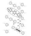
図10は量子部15の第3の実装例を示す図である。図10に示すように偏極源部位(ペンタセン基)とレザバー部位(p-ターフェニル誘導体)が修飾された分子がドープされたホスト分子(p-ターフェニル-2 H14)の単結晶でも、実施の形態1で説明したエクストリーム量子学習、及び実施の形態2で説明した量子レザバー計算を実装することができる。
図11は量子部15の第4の実装例を示す図である。図11は電子スピン系による実装例を示したものである。図11に示すようにレザバー分子(TEMPOラジカルオリゴマー)と偏極源分子(BDPAラジカル:電子スピンはEB で表示)がドープされたホスト分子(ベンゼン)の単結晶でも実施の形態1で説明したエクストリーム量子学習、及び実施の形態2で説明した量子レザバー計算を実装することができる。オリゴマーの端のTEMPO基の電子スピンが入力及び測定を担うスピンとなり、それ以外のTEMPO基の電子スピンがレザバーの量子ダイナミクスを担う。この系では、BDPAの電子スピンが格子との結合で初期化されるものとする。
図12は量子部15の第5の実装例を示す図である。図12に示すようにレザバー分子(TEMPOオリゴマー:電子スピンはET で表示)がドープされた偏極源分子(BDPA)をホストとする単結晶でも単結晶でも実施の形態1で説明したエクストリーム量子学習、及び実施の形態2で説明した量子レザバー計算を実装することができる。オリゴマーの端のTEMPO基の電子スピンが入力及び測定を担うスピンとなり、それ以外のTEMPO基の電子スピンがレザバーの量子ダイナミクスを担う。この系では、BDPAの電子スピンが格子との結合で初期化されるものとする。
また、図11及び図12では、電子スピン系による実装例を示したが、電子スピンと核スピンのハイブリッド系でも実装可能である。例えば、図11の系で、TEMPOのオリゴマー分子の電子スピンが入力及び測定を担い、TEMPOオリゴマー分子の19Fスピンがレザバーの量子ダイナミクスを担うように量子レザバーに対する制御を行ってもよい。
本発明によって現代社会に取り巻く様々な問題を解くことができるようになる。従来のレザバー計算がフォンノイマン型より優れた性能を持つとされている応用例ならほとんどすべて量子レザバー計算でさらに優れた性能を発揮できる。このような応用例としてカオス時系列予測が考えられ、最も市場価値の高いものとしては株価予測が考えられる。ほかにも例えば、地震変動の予測、生体シグナルの解析、ロボットの自律制御や無線通信システムの非線形補償等へも応用可能である。また機械学習にも用いることが可能で、画像認識、音声認識、人工知能などへの応用が期待される。
今回開示された実施の形態は、全ての点で例示であって、制限的なものではないと考えられるべきである。本発明の範囲は、上述した意味ではなく、請求の範囲によって示され、請求の範囲と均等の意味及び範囲内での全ての変更が含まれることが意図される。
11 制御部(時間発展制御部、重み決定部)
12 記憶部
13 信号入力部
14 信号読出部
15 量子部(量子レザバー)
20 冷却部(初期化部)
21 冷却系
A1,A2 入力スピン
B1,B2 測定スピン
N ノードスピン
R0 偏極源
R1,R2 冷却スピン
R 冷媒スピン
12 記憶部
13 信号入力部
14 信号読出部
15 量子部(量子レザバー)
20 冷却部(初期化部)
21 冷却系
A1,A2 入力スピン
B1,B2 測定スピン
N ノードスピン
R0 偏極源
R1,R2 冷却スピン
R 冷媒スピン
Claims (10)
- 物質中の核スピン又は電子スピンの状態を表すキューディットを複数含んだ量子系により構成された量子レザバーを備え、
前記量子系は、第1共鳴周波数を有する第1電磁場によって他のスピンとの間のスピン間相互作用が制御される入力スピンと、互いにスピン間相互作用が働く複数のノードスピンと、前記第1共鳴周波数とは異なる第2共鳴周波数を有する第2電磁場によって他のスピンとの間のスピン間相互作用が制御される測定スピンとを含み、
前記第2電磁場を照射することにより前記測定スピンと前記ノードスピンとの間のスピン間相互作用を制御し、該スピン間相互作用を制御した状態にて、前記入力スピンを通じて信号を入力する信号入力部と、
前記第1及び第2電磁場を照射することにより前記入力スピンと前記ノードスピンとの間のスピン間相互作用、及び前記測定スピンと前記ノードスピンとの間のスピン間相互作用を制御し、前記ノードスピン間のスピン間相互作用により前記量子系を時間発展させる時間発展制御部と、
前記第1電磁場の照射を維持して前記第2電磁場の照射を停止することにより、前記入力スピンと他のスピンとの間のスピン間相互作用を制御した状態にて、前記測定スピンと前記ノードスピンとの間のスピン間相互作用を復活させ、前記測定スピンを通じて信号を読み出す信号読出部と
を更に備える量子計算装置。 - 前記入力スピンを通じて入力する信号と前記測定スピンを通じて読み出す信号との関係が既知である入出力関係を再現するように、前記信号読出部が読み出す信号に対する線形重みを学習により決定する重み決定部
を備える請求項1に記載の量子計算装置。 - 前記入力スピンに信号を入力する都度、前記入力スピンの偏極状態を初期化する初期化部
を備える請求項1又は請求項2に記載の量子計算装置。 - 前記初期化部は、
偏極源と、
該偏極源により初期化可能な冷却スピンと、
前記冷却スピンと前記入力スピンとの間に介在する冷媒スピンと
を含み、
前記偏極源により前記冷却スピンを初期化した後に、前記冷媒スピンを前記冷却スピン及び前記入力スピンの双方に結合させることにより、前記入力スピンの偏極状態を初期化する
請求項3に記載の量子計算装置。 - 前記偏極源は、格子又は高偏極電子を含み、
スピン格子緩和又は動的核偏極を用いて前記冷却スピンの偏極状態を初期化する
請求項4に記載の量子計算装置。 - 前記物質は、原子核による核スピンクラスターのアンサンブル、又は電子による電子スピンクラスターのアンサンブルを含む
請求項1から請求項5の何れか1つに記載の量子計算装置。 - 前記物質は、p-ターフェニル誘導体分子を含む
請求項1から請求項6の何れか1つに記載の量子計算装置。 - 前記物質は、レザバー分子であるp-ターフェニル誘導体分子と、偏極源分子であるペンタセンとがホスト分子にドープされた単結晶である
請求項3から請求項6の何れか1つに記載の量子計算装置。 - 物質中の核スピン又は電子スピンの状態を表すキューディットを複数含んだ量子系を用いて量子計算を行う量子計算方法であって、
前記量子系に含まれる測定スピンと複数のノードスピンとの間のスピン間相互作用を制御すべく、第2共鳴周波数を有する第2電磁場を照射し、
前記スピン間相互作用を制御した状態にて、前記量子系に含まれる入力スピンを通じて信号を入力し、
前記スピン間相互作用を制御した状態にて、更に前記入力スピンと前記複数のノードスピンとの間のスピン間相互作用を制御すべく、前記第2共鳴周波数とは異なる第1共鳴周波数を有する第1電磁場を照射し、
前記入力スピンと前記複数のノードスピンとの間のスピン間相互作用、及び前記測定スピンと前記複数のノードスピンとの間のスピン間相互作用を制御した状態にて、前記ノードスピン間のスピン間相互作用により前記量子系を時間発展させ、
前記第1電磁場の照射を維持して前記第2電磁場の照射を停止し、
前記入力スピンと前記複数のノードスピンとの間のスピン間相互作用を制御し、前記測定スピンと前記ノードスピンとの間のスピン間相互作用を復活させた状態にて、前記測定スピンを通じて前記量子系から信号を読み出す
量子計算方法。 - 偏極源と、該偏極源により初期化可能な冷却スピンと、前記冷却スピンと前記入力スピンとの間に介在する冷媒スピンとを備える初期化部を用いて、前記偏極源により前記冷却スピンを初期化した後、前記冷媒スピンを前記冷却スピン及び前記入力スピンの双方に結合させることにより、前記入力スピンに信号を入力する都度、前記入力スピンの偏極状態を初期化する
請求項9に記載の量子計算方法。
Applications Claiming Priority (2)
| Application Number | Priority Date | Filing Date | Title |
|---|---|---|---|
| JP2017-021450 | 2017-02-08 | ||
| JP2017021450A JP6853531B2 (ja) | 2017-02-08 | 2017-02-08 | 量子計算装置及び量子計算方法 |
Publications (1)
| Publication Number | Publication Date |
|---|---|
| WO2018147208A1 true WO2018147208A1 (ja) | 2018-08-16 |
Family
ID=63108343
Family Applications (1)
| Application Number | Title | Priority Date | Filing Date |
|---|---|---|---|
| PCT/JP2018/003750 Ceased WO2018147208A1 (ja) | 2017-02-08 | 2018-02-05 | 量子計算装置及び量子計算方法 |
Country Status (2)
| Country | Link |
|---|---|
| JP (1) | JP6853531B2 (ja) |
| WO (1) | WO2018147208A1 (ja) |
Cited By (6)
| Publication number | Priority date | Publication date | Assignee | Title |
|---|---|---|---|---|
| US11580435B2 (en) | 2018-11-13 | 2023-02-14 | Atom Computing Inc. | Scalable neutral atom based quantum computing |
| US11586968B2 (en) | 2018-11-13 | 2023-02-21 | Atom Computing Inc. | Scalable neutral atom based quantum computing |
| US11797873B2 (en) | 2020-03-02 | 2023-10-24 | Atom Computing Inc. | Scalable neutral atom based quantum computing |
| US11875227B2 (en) | 2022-05-19 | 2024-01-16 | Atom Computing Inc. | Devices and methods for forming optical traps for scalable trapped atom computing |
| US11995512B2 (en) | 2018-11-13 | 2024-05-28 | Atom Computing Inc. | Scalable neutral atom based quantum computing |
| US12462174B2 (en) | 2020-03-02 | 2025-11-04 | Atom Computing Inc. | Scalable neutral atom based quantum computing |
Families Citing this family (2)
| Publication number | Priority date | Publication date | Assignee | Title |
|---|---|---|---|---|
| US11695483B2 (en) * | 2020-02-19 | 2023-07-04 | International Business Machines Corporation | Target qubit decoupling in an echoed cross-resonance gate |
| EP4443343A4 (en) | 2021-11-30 | 2025-01-15 | Fujitsu Limited | QUANTUM DEVICE, QUANTUM COMPUTING DEVICE AND QUANTUM COMPUTING METHOD |
Citations (1)
| Publication number | Priority date | Publication date | Assignee | Title |
|---|---|---|---|---|
| JP2014056909A (ja) * | 2012-09-12 | 2014-03-27 | Univ Of Shiga Prefecture | 量子コンピュータ |
Family Cites Families (2)
| Publication number | Priority date | Publication date | Assignee | Title |
|---|---|---|---|---|
| JP3854059B2 (ja) * | 1999-11-18 | 2006-12-06 | 株式会社東芝 | 量子情報処理方法および量子情報処理装置 |
| US8023828B2 (en) * | 2005-10-17 | 2011-09-20 | Hewlett-Packard Development Company, L.P. | Quantum information conversion between matter and light representations |
-
2017
- 2017-02-08 JP JP2017021450A patent/JP6853531B2/ja not_active Expired - Fee Related
-
2018
- 2018-02-05 WO PCT/JP2018/003750 patent/WO2018147208A1/ja not_active Ceased
Patent Citations (1)
| Publication number | Priority date | Publication date | Assignee | Title |
|---|---|---|---|---|
| JP2014056909A (ja) * | 2012-09-12 | 2014-03-27 | Univ Of Shiga Prefecture | 量子コンピュータ |
Non-Patent Citations (2)
| Title |
|---|
| "Quantum Computation and Quantum Information II", article NIELSEN, M., pages: 207 - 233 * |
| KITAGAWA, MASAHIRO ET AL.: "Development of Molecular Spin Quantum Computers/Quantum Information Processing Systems", CHEMISTRY & CHEMICAL INDUSTRY, vol. 62 -1, January 2009 (2009-01-01), pages 031 - 032 * |
Cited By (8)
| Publication number | Priority date | Publication date | Assignee | Title |
|---|---|---|---|---|
| US11580435B2 (en) | 2018-11-13 | 2023-02-14 | Atom Computing Inc. | Scalable neutral atom based quantum computing |
| US11586968B2 (en) | 2018-11-13 | 2023-02-21 | Atom Computing Inc. | Scalable neutral atom based quantum computing |
| US11995512B2 (en) | 2018-11-13 | 2024-05-28 | Atom Computing Inc. | Scalable neutral atom based quantum computing |
| US12112238B2 (en) | 2018-11-13 | 2024-10-08 | Atom Computing Inc. | Scalable neutral atom based quantum computing |
| US11797873B2 (en) | 2020-03-02 | 2023-10-24 | Atom Computing Inc. | Scalable neutral atom based quantum computing |
| US12106183B2 (en) | 2020-03-02 | 2024-10-01 | Atom Computing Inc. | Scalable neutral atom based quantum computing |
| US12462174B2 (en) | 2020-03-02 | 2025-11-04 | Atom Computing Inc. | Scalable neutral atom based quantum computing |
| US11875227B2 (en) | 2022-05-19 | 2024-01-16 | Atom Computing Inc. | Devices and methods for forming optical traps for scalable trapped atom computing |
Also Published As
| Publication number | Publication date |
|---|---|
| JP6853531B2 (ja) | 2021-03-31 |
| JP2018128857A (ja) | 2018-08-16 |
Similar Documents
| Publication | Publication Date | Title |
|---|---|---|
| JP6853531B2 (ja) | 量子計算装置及び量子計算方法 | |
| Elben et al. | The randomized measurement toolbox | |
| Harrington et al. | Engineered dissipation for quantum information science | |
| Mohseni et al. | Ising machines as hardware solvers of combinatorial optimization problems | |
| Katz et al. | Demonstration of three-and four-body interactions between trapped-ion spins | |
| Lau et al. | NISQ computing: where are we and where do we go? | |
| Zimmermann et al. | Observing spatio-temporal dynamics of excitable media using reservoir computing | |
| Blume-Kohout et al. | Robust, self-consistent, closed-form tomography of quantum logic gates on a trapped ion qubit | |
| EP3815006B1 (en) | Efficient cooling of ion chains for quantum computation | |
| Fujii et al. | Harnessing disordered-ensemble quantum dynamics for machine learning | |
| Friedenauer et al. | Simulating a quantum magnet with trapped ions | |
| Araz et al. | Hybrid quantum simulations with qubits and qumodes on trapped-ion platforms | |
| Zlokapa et al. | Quantum adiabatic machine learning by zooming into a region of the energy surface | |
| Wang et al. | Quantum computing in a statistical context | |
| US20210073668A1 (en) | Computer System and Method for Implementing a Conditional Reflection Operator on a Quantum Computer | |
| WO2007006144A1 (en) | Systems, methods and apparatus for factoring numbers | |
| Zhang et al. | Digital quantum simulation of the statistical mechanics of a frustrated magnet | |
| Li et al. | Experimental study of Forrelation in nuclear spins | |
| US20230419154A1 (en) | Method and apparatus for machine learning using a quantum system | |
| Mølmer | Hypothesis testing with open quantum systems | |
| Klassert et al. | Variational learning of quantum ground states on spiking neuromorphic hardware | |
| Rohling et al. | Tomography scheme for two spin-1 2 qubits in a double quantum dot | |
| Liu et al. | Optimal and robust in-situ quantum hamiltonian learning through parallelization | |
| JP2024503431A (ja) | 量子計算方法及び量子演算制御レイアウト | |
| Cooke et al. | Reinforcement learning for optimal control of spin magnetometers |
Legal Events
| Date | Code | Title | Description |
|---|---|---|---|
| 121 | Ep: the epo has been informed by wipo that ep was designated in this application |
Ref document number: 18751607 Country of ref document: EP Kind code of ref document: A1 |
|
| NENP | Non-entry into the national phase |
Ref country code: DE |
|
| 122 | Ep: pct application non-entry in european phase |
Ref document number: 18751607 Country of ref document: EP Kind code of ref document: A1 |