WO2018143256A1 - 電子システム - Google Patents
電子システム Download PDFInfo
- Publication number
- WO2018143256A1 WO2018143256A1 PCT/JP2018/003169 JP2018003169W WO2018143256A1 WO 2018143256 A1 WO2018143256 A1 WO 2018143256A1 JP 2018003169 W JP2018003169 W JP 2018003169W WO 2018143256 A1 WO2018143256 A1 WO 2018143256A1
- Authority
- WO
- WIPO (PCT)
- Prior art keywords
- unit
- real space
- image
- acquisition unit
- electronic system
- Prior art date
- Legal status (The legal status is an assumption and is not a legal conclusion. Google has not performed a legal analysis and makes no representation as to the accuracy of the status listed.)
- Ceased
Links
Images




Classifications
-
- F—MECHANICAL ENGINEERING; LIGHTING; HEATING; WEAPONS; BLASTING
- F24—HEATING; RANGES; VENTILATING
- F24F—AIR-CONDITIONING; AIR-HUMIDIFICATION; VENTILATION; USE OF AIR CURRENTS FOR SCREENING
- F24F11/00—Control or safety arrangements
- F24F11/62—Control or safety arrangements characterised by the type of control or by internal processing, e.g. using fuzzy logic, adaptive control or estimation of values
- F24F11/63—Electronic processing
- F24F11/64—Electronic processing using pre-stored data
-
- F—MECHANICAL ENGINEERING; LIGHTING; HEATING; WEAPONS; BLASTING
- F24—HEATING; RANGES; VENTILATING
- F24F—AIR-CONDITIONING; AIR-HUMIDIFICATION; VENTILATION; USE OF AIR CURRENTS FOR SCREENING
- F24F11/00—Control or safety arrangements
- F24F11/62—Control or safety arrangements characterised by the type of control or by internal processing, e.g. using fuzzy logic, adaptive control or estimation of values
- F24F11/63—Electronic processing
- F24F11/65—Electronic processing for selecting an operating mode
-
- G—PHYSICS
- G05—CONTROLLING; REGULATING
- G05B—CONTROL OR REGULATING SYSTEMS IN GENERAL; FUNCTIONAL ELEMENTS OF SUCH SYSTEMS; MONITORING OR TESTING ARRANGEMENTS FOR SUCH SYSTEMS OR ELEMENTS
- G05B15/00—Systems controlled by a computer
- G05B15/02—Systems controlled by a computer electric
-
- G—PHYSICS
- G06—COMPUTING OR CALCULATING; COUNTING
- G06F—ELECTRIC DIGITAL DATA PROCESSING
- G06F3/00—Input arrangements for transferring data to be processed into a form capable of being handled by the computer; Output arrangements for transferring data from processing unit to output unit, e.g. interface arrangements
- G06F3/01—Input arrangements or combined input and output arrangements for interaction between user and computer
-
- H—ELECTRICITY
- H04—ELECTRIC COMMUNICATION TECHNIQUE
- H04N—PICTORIAL COMMUNICATION, e.g. TELEVISION
- H04N13/00—Stereoscopic video systems; Multi-view video systems; Details thereof
- H04N13/10—Processing, recording or transmission of stereoscopic or multi-view image signals
- H04N13/194—Transmission of image signals
-
- H—ELECTRICITY
- H04—ELECTRIC COMMUNICATION TECHNIQUE
- H04N—PICTORIAL COMMUNICATION, e.g. TELEVISION
- H04N13/00—Stereoscopic video systems; Multi-view video systems; Details thereof
- H04N13/30—Image reproducers
- H04N13/363—Image reproducers using image projection screens
-
- H—ELECTRICITY
- H04—ELECTRIC COMMUNICATION TECHNIQUE
- H04N—PICTORIAL COMMUNICATION, e.g. TELEVISION
- H04N5/00—Details of television systems
- H04N5/64—Constructional details of receivers, e.g. cabinets or dust covers
-
- H—ELECTRICITY
- H04—ELECTRIC COMMUNICATION TECHNIQUE
- H04N—PICTORIAL COMMUNICATION, e.g. TELEVISION
- H04N5/00—Details of television systems
- H04N5/74—Projection arrangements for image reproduction, e.g. using eidophor
-
- H—ELECTRICITY
- H04—ELECTRIC COMMUNICATION TECHNIQUE
- H04N—PICTORIAL COMMUNICATION, e.g. TELEVISION
- H04N7/00—Television systems
- H04N7/18—Closed-circuit television [CCTV] systems, i.e. systems in which the video signal is not broadcast
-
- F—MECHANICAL ENGINEERING; LIGHTING; HEATING; WEAPONS; BLASTING
- F24—HEATING; RANGES; VENTILATING
- F24F—AIR-CONDITIONING; AIR-HUMIDIFICATION; VENTILATION; USE OF AIR CURRENTS FOR SCREENING
- F24F2110/00—Control inputs relating to air properties
- F24F2110/20—Humidity
-
- F—MECHANICAL ENGINEERING; LIGHTING; HEATING; WEAPONS; BLASTING
- F24—HEATING; RANGES; VENTILATING
- F24F—AIR-CONDITIONING; AIR-HUMIDIFICATION; VENTILATION; USE OF AIR CURRENTS FOR SCREENING
- F24F2110/00—Control inputs relating to air properties
- F24F2110/50—Air quality properties
- F24F2110/60—Odour
-
- Y—GENERAL TAGGING OF NEW TECHNOLOGICAL DEVELOPMENTS; GENERAL TAGGING OF CROSS-SECTIONAL TECHNOLOGIES SPANNING OVER SEVERAL SECTIONS OF THE IPC; TECHNICAL SUBJECTS COVERED BY FORMER USPC CROSS-REFERENCE ART COLLECTIONS [XRACs] AND DIGESTS
- Y02—TECHNOLOGIES OR APPLICATIONS FOR MITIGATION OR ADAPTATION AGAINST CLIMATE CHANGE
- Y02B—CLIMATE CHANGE MITIGATION TECHNOLOGIES RELATED TO BUILDINGS, e.g. HOUSING, HOUSE APPLIANCES OR RELATED END-USER APPLICATIONS
- Y02B30/00—Energy efficient heating, ventilation or air conditioning [HVAC]
- Y02B30/70—Efficient control or regulation technologies, e.g. for control of refrigerant flow, motor or heating
Definitions
- the present invention relates to an electronic system.
- a technique related to the VR technique includes a three-dimensional image projector that projects a three-dimensional image in a space from a light source provided at an appropriate position on the ceiling of a room (see Patent Document 1).
- Patent Document 1 a virtual space is displayed, and it is not possible to experience as if in a real place.
- an object of the present invention is to provide an electronic system in which a user can experience as if in a real place away from the place where the user is.
- An electronic system that achieves the above object includes a spatial image acquisition unit that acquires a first real space image that is visually recognized in a predetermined first real space, and the first image acquired by the spatial image acquisition unit.
- a display unit that virtually displays a real space image in a second real space that is distant from the first real space, and is recognized by five senses other than vision in the first real space that are different from the first real space image.
- a spatial information acquisition unit that acquires the first real space information, and a reproduction unit that reproduces the first real space information acquired by the spatial information acquisition unit in the second real space.
- the user can experience as if he / she is in a real place away from the place where the user is.
- FIG. 1 is a block diagram illustrating an electronic system according to a first embodiment. It is a sequence diagram shown about the exchange of information in the electronic system which concerns on 1st Embodiment. It is a flowchart shown about the dialogue with the remote person according to the first embodiment.
- the electronic system 100 according to the present embodiment is a medical system used when a hospitalized patient (user) desires an experience as if he / she went to a place where he / she was scheduled to participate if he / she was not hospitalized. explain.
- the electronic system 100 includes an aerial image acquisition unit 10, a display unit 20, a spatial information acquisition unit, and a reproduction unit.
- the aerial image acquisition unit 10 acquires a first real space image that is visually recognized in a predetermined first real space.
- the display unit 20 virtually displays the first real space image acquired by the aerial image acquisition unit 10 in a second real space separated from the first real space.
- the spatial information acquisition unit includes an audio acquisition unit 30, an odor acquisition unit 50, and an ambient air acquisition unit 70, and is recognized in the first real space by the five senses other than the visual sense different from the first real space image. Get spatial information.
- the reproduction unit includes an audio output unit 40, an odor generation unit 60, and an ambient air generation unit 80, and reproduces the first real space information acquired by the spatial information acquisition unit in the second real space.
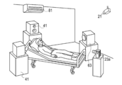
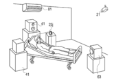
- the first real space corresponds to the relative's house of the patient P as shown in FIG. 2 and the second real space is the patient's room as shown in FIG.
- the location of the first real space and the second real space is not limited to a house or a hospital as long as the electronic system 100 described below can be installed.
- care facilities nursery schools (nursery schools), wedding halls, or any two locations selected from the destination resorts that were originally planned to go to, or even separated conference rooms Good. Details will be described below.
- the aerial image acquisition unit 10 includes a camera 11, a screen 12, a projector 13, a communication unit 14, and a control unit 15.
- the camera 11 is installed in a room of a house where a relative or the like who communicates (communication) with the patient P in the present embodiment, and captures a spatial image of the relative or the like.
- the aerial image in this specification means an image or a video.
- the screen 12 is provided for projecting an image projected by the projector 13. As shown in FIG. 3, the projector 13 displays an image using a so-called projection mapping technique.
- the screen 12 is configured to be installed in a room where relatives are present.
- the screen 12 is not limited to this, and the screen 12 may be a wall surface of a room with relatives as shown in FIG.
- the projection of the aerial image in FIG. 2 is the same as in FIG.
- the projector 13 may be a conventionally known liquid crystal projector, DLP (Digital Light Processing) projector, LCOS (Liquid Crystal On Display) projector, or the like.
- DLP Digital Light Processing
- LCOS Liquid Crystal On Display
- the communication unit 14 is configured by hardware or the like used for wireless communication, and transmits / receives data such as video in order to communicate between the patient P and a relative or the like in a remote place using an Internet line or the like.
- the control unit 15 includes a CPU, a RAM, a ROM, and the like, and controls the communication unit 14 from the camera 11.
- a program necessary for projection mapping is recorded in the ROM of the control unit 15, and an image captured by the camera 21 of the display unit 20 is corrected according to the shape of the screen 12. Thereby, the image of the hospital side where the patient P exists according to the shape of the screen 12 can be projected.
- the display unit 20 includes a camera 21, a screen 22, a projector 23, a communication unit 24, a control unit 25, and a remote controller 26.
- the camera 21 is configured by a conventionally known camera similarly to the camera 11, and images the range of the patient P and its surroundings in the room of the patient P.
- the screen 22 is installed in the room where the patient P is located as shown in FIGS. 1 and 3, the screen 22 is illustrated as being flat and free of a pattern or the like for convenience, but there may be some unevenness or a pattern may be formed.
- the screen 22 corresponds to a projection unit having a projection surface in this specification.
- the projector 23 Since the projector 23 is the same as the projector 13, a detailed description thereof is omitted. Note that the projector 23 corresponds to a video output unit that projects a video of a house in the first real space in this specification.
- the communication unit 24 is configured by the same hardware as the communication unit 14, and transmits and receives video data transmitted from a remote place such as a house.
- the control unit 25 includes a CPU, a RAM, a ROM, and the like, and controls the projector 23 and the communication unit 24. Similar to the control unit 15, a program necessary for projection mapping is recorded in the ROM of the control unit 25, and the image acquired from the aerial image acquisition unit 10 is corrected according to the shape of the screen 22 captured by the camera 21. .
- the projection mapping program stored in the ROM of the control unit 25 corresponds to a correction unit that corrects an image in accordance with the properties of the projection surface in this specification.
- the remote control 26 has the same configuration as a conventionally known configuration, and includes a configuration such as a button and a communication unit, and is configured to send a signal for switching on / off of the configuration of the display unit 20.
- the sound acquisition unit 30 includes a microphone 31, a speaker 32, a communication unit 33, and a control unit 34.
- the microphone 31 is installed in a room of a relative's house, and acquires voices emitted from the relatives and surrounding sounds.
- the speaker 32 is installed in a room of a relative's house, and outputs the patient P and surrounding sounds acquired at a remote hospital.
- the communication unit 33 is configured in the same manner as the communication unit 14, and transmits / receives relatives' voices to / from the hospital where the patient P is located.
- the control unit 34 includes a CPU, a RAM, a ROM, and the like, and controls the communication unit 33 from the microphone 31.
- the audio output unit 40 includes a speaker 41, a microphone 42, a communication unit 43, and a control unit 44.
- the speaker 41 is installed in a hospital room where the patient P is present, and outputs the sound of relatives and the like and the surrounding sound transmitted from the communication unit 33.
- the microphone 42 is installed in a room of a hospital where the patient P is present, and acquires voices emitted by the patient P and surrounding voices.
- the communication unit 43 is configured in the same manner as the communication unit 14, and transmits and receives data related to voice with the communication unit 33.
- the control unit 44 includes a CPU, a RAM, a ROM, and the like, and controls the communication unit 43 from the speaker 41.
- the odor acquisition unit 50 includes an odor sensor 51, a communication unit 52, and a control unit 53.
- the odor sensor 51 corresponds to a detection unit that detects an odor in a room of a house corresponding to a first real space where a relative such as a house is located.
- a plurality of odor sensors 51 can be installed according to the odor to be acquired.
- the odor sensor 51 can be installed according to the place where the electronic system 100 is installed, for example, in the living room or bedroom, a sensor that detects the odor of coffee or tea, or a sensor that detects the odor of furniture or the like.
- a sensor that detects the odor of coffee or tea or a sensor that detects the odor of furniture or the like.
- coffee or the like is prepared in a room where relatives are present as an example.
- the communication unit 52 is configured by the same hardware as the communication unit 14, and transmits information related to the odor acquired by the odor sensor 51 to the odor generating unit 60.
- the control unit 53 controls the odor sensor 51 and the communication unit 52.
- the odor generating unit 60 includes a cartridge 61, a blending unit 62, a generator 63, a communication unit 64, and a control unit 65.
- a plurality of cartridges 61 are prepared and each have a smell of food or drink or furniture, for example, in order to reproduce the scent of a room with a relative who interacts with the patient P, such as a relative.
- the blending unit 62 blends a plurality of scents contained in the cartridge 61 in order to reproduce the same scent as the actual house based on the information acquired from the communication unit 64.
- the generator 63 is configured by a fan or the like, and blows the odor blended by the blending unit 62 toward the patient P.
- the communication unit 64 communicates with the communication unit 52 of the remote odor acquisition unit 50 and acquires data related to the odor component measured by the odor acquisition unit 50.
- the control unit 65 includes a CPU, a RAM, a ROM, and the like, and controls the blending unit 62 to the communication unit 64.
- the ambient air acquisition unit 70 includes a thermometer 71, an anemometer 72, a communication unit 73, and a control unit 74.
- the thermometer 71 is configured by a known digital thermometer or the like, and acquires the temperature of a room where a relative is in the house as digital data as shown in FIG.
- the anemometer 72 is configured by a known anemometer, and measures the wind speed and the like of a room in the house where relatives are present.
- the thermometer 71 and the anemometer 72 when the temperature in the room where the relative is located is adjusted using an air conditioner or the like, the temperature and wind of the space where the patient P is located are the same as in the room where the relative is located. Can be adjusted.
- thermometer 71 corresponds to a measurement unit that measures the ambient temperature in a room where relatives and the like are present in the house corresponding to the first real space.
- the anemometer 72 corresponds to another measurement unit that measures the wind speed in a room where a relative or the like in the first real space is present.
- the communication unit 73 transmits the data acquired by the thermometer 71 and the anemometer 72 to the communication unit 82 of the ambient air generation unit 80 of the patient P.
- the control unit 74 is configured by a CPU, a RAM, a ROM, and the like as described above, and controls the thermometer 71 to the communication unit 73.
- the ambient air generation unit 80 includes an air conditioner 81, a communication unit 82, and a control unit 83.
- the air conditioner 81 includes a known compressor, evaporator, condenser, expansion valve, and the like, and adjusts the temperature and wind speed in the room where the patient P is located.
- the air conditioner 81 corresponds to a preparation unit that adjusts the temperature of a room in the hospital where the patient P corresponding to the second real space is in accordance with the temperature measured by the thermometer 71.
- the air conditioner 81 corresponds to a blower that outputs the wind at the wind speed measured by the anemometer 72 in the second real space.
- the communication unit 82 receives data related to the temperature and wind speed of the room where the relatives are present from the communication unit 73 of the ambient air acquisition unit 70.
- the control unit 83 controls the air conditioner 81 and the communication unit 82.
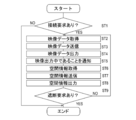
- FIG. 5 is a sequence diagram showing exchange of information in the electronic system according to the present embodiment.
- FIG. 6 is a flowchart for explaining a dialogue between remote places using the electronic system according to the present embodiment.
- the use of the electronic system 100 will be described.
- ST1 connection request
- ST2 connection request
- ST3 video data captured through the communication units 14 and 24 is transmitted to the hospital side
- the video data is projected onto the screen 22 by the projector 23 of the display unit 20, so that the patient P can visually recognize the video (ST4).
- the communication unit 14 When the video data is transmitted from the aerial image acquisition unit 10, the communication unit 14 notifies the audio acquisition unit 30, the odor acquisition unit 50, and the ambient air acquisition unit 70 that there is a request for output of video data. (ST5).
- the notification is performed in the sound acquisition unit 30, the odor acquisition unit 50, and the ambient air acquisition unit 70, the sound acquisition unit 30, the odor acquisition unit 50, and the ambient air acquisition unit 70 are substantially the same as the aerial image acquisition unit 10.
- Surrounding voice, odor, temperature, and wind speed data are acquired within the range (ST6).
- the data acquired by the voice acquisition unit 30, the odor acquisition unit 50, and the ambient air acquisition unit 70 are transmitted to the communication units 43, 64, and 82 by the communication units 33, 52, and 73 (ST7).
- the transmitted spatial information is output around the patient P by the speaker 41 of the audio output unit 40, the generator 63 of the odor generating unit 60, and the air conditioner 81 of the ambient air generating unit 80 (ST8).
- the output of the spatial information in ST8 from the acquisition of the video data in ST2 of FIG. 6 is continued as long as there is no cutoff request for connection with the house corresponding to the first real space from the remote control 26 of the patient P (ST9: NO).
- the relative can interact with the patient P using the camera 11, the screen 12, the projector 13, the microphone 31, and the speaker 32.
- the spatial image and the spatial information from the display unit 20, the audio output unit 40, the odor generating unit 60, and the ambient air generating unit 80 are displayed. Stop output.
- a signal requesting output of video data is transmitted from the communication unit 24 to the communication unit 14 of the aerial image acquisition unit 10 by the control unit 25 of the display unit 20.
- the communication unit 14 of the aerial image acquisition unit 10 operates the camera 11 to image relatives and surrounding backgrounds in the imaging range of the camera 11 and acquire video data (S2).
- the communication unit 14 transmits the video data captured by the camera 11 to the communication unit 24 of the display unit 20 (S3).
- the projector 23 outputs the video of the house to the screen 22 as shown in FIG. 3 (S4).
- the communication unit 14 of the aerial image acquisition unit 10 sends a signal notifying that an output request has been made when the signal is received, to the communication unit 33 of the voice acquisition unit 30, the communication unit 52 of the odor acquisition unit 50, and It transmits to the communication part 73 of the ambient air acquisition part 70 (S5).
- the control unit 34 controls the microphone 31 to acquire relatives and surrounding voices in the range of the surrounding number m that is the acquisition region (S6). .
- the audio data acquired by the microphone 31 is transmitted to the communication unit 43 of the audio output unit 40 through the communication unit 33 (S7), and the audio data transmitted from the speaker 41 is output toward the patient P (S8).
- the odor sensor 51 acquires odor data within a range of several m (S6).
- the acquired data is transmitted by the communication unit 64 of the odor generating unit 60 through the communication unit 52 (S7).
- Data received by the communication unit 64 is selected by the control unit 65 from the cartridge 61 and a necessary odor component is blended by the blending unit 62 and output around the patient P (S8).
- the control unit 74 activates the thermometer 71 and the anemometer 72, and measures the temperature and the wind speed within a range of several meters (S6). . Data measured by the thermometer 71 and the anemometer 72 is transmitted by the communication unit 73 to the communication unit 82 of the ambient air generation unit 80 (S7).
- the air conditioner 81 of the ambient air generation unit 80 adjusts the temperature and wind speed in the room where the patient P is present based on the received information (S8).
- the button on the remote control 26 of the display unit 20 is pressed (S9).
- the control unit 25 in the display unit 20 stops the output of the projector 23 and stops the projection of the image on the screen 22 (S10).
- the control unit 15 stops the acquisition of video data by the camera 11 (S11).
- the communication unit 24 notifies the communication units 43, 64, 73 that the output stop signal has been transmitted (S12).
- the communication unit 43 the output of the voice is stopped by the control unit 44 (S13).
- the control part 65 will stop operation
- the control unit 83 stops the operation of the air conditioner 81 (S13).
- the communication unit 43 When the communication unit 43 receives a signal from the communication unit 24, the communication unit 43 notifies the communication unit 33 of a voice data acquisition stop request (S14).
- the control unit 34 controls the microphone 31 to stop the acquisition of audio data in the house room (S15).
- the communication unit 64 When the communication unit 64 receives a signal from the communication unit 24, the communication unit 64 notifies the communication unit 52 of an odor data acquisition stop request (S14). In response to this, the control unit 55 stops the operation of the odor sensor 51 (S15).
- the communication unit 82 When the communication unit 82 receives a signal from the communication unit 24, the communication unit 82 notifies the communication unit 73 of a request to stop acquiring ambient air data (S14). In response to this, the control unit 74 stops the acquisition of the temperature data and the wind speed data by the thermometer 71 and the anemometer 72 (S15).
- the electronic system 100 of this embodiment is configured to include the aerial image acquisition unit 10, the display unit 20, the spatial information acquisition unit, and the reproduction unit.
- the aerial image acquisition unit 10 acquires an aerial image that is visually recognized in a house corresponding to a predetermined first real space.
- the display unit 20 virtually displays the first real space image acquired by the aerial image acquisition unit 10 in a hospital that is a second real space away from the house that is the first real space.
- the spatial information acquisition unit is configured by the audio acquisition unit 30, the odor acquisition unit 50, and the ambient air acquisition unit 70, and is recognized by the five senses other than the visual sense different from the first real space image in the house which is the first real space. Obtain spatial information.
- the reproduction unit is configured by the audio output unit 40, the odor generation unit 60, and the ambient air generation unit 80, and the first real space information of the house which is the first real space information acquired by the space information acquisition unit is stored in the hospital where the patient P is located. To reproduce.
- the patient P is in a house away from the place where the patient P is located when the physical condition suddenly deteriorates and the school event or travel that was originally planned cannot be performed. You can experience as if you were.
- the patient P can experience the illusion as if he / she shares the same space as a relative in a remote area.
- the display unit 20 also includes a projector 23 that projects a spatial image of the house corresponding to the first real space, a screen 22 that displays the spatial image output from the projector 23, and a program that corrects the spatial image in accordance with the properties of the screen 22. Is stored in the ROM of the control unit 25. Therefore, a spatial image on the house side (first real space) can be projected without being restricted by the properties of the screen 22 installed in the room where the patient P is present, and the sense of reality can be improved.
- the odor acquisition unit 50 includes an odor sensor 51 for detecting the odor of the house room corresponding to the first real space, and the odor generation unit 60 transmits the odor corresponding to the odor detected by the odor sensor 51 in the hospital of the patient P. It is configured to output in one room. Therefore, not only visual and auditory senses but also olfactory senses can be used to reproduce more realistic situations, and user satisfaction can be improved.
- the ambient air acquisition unit 70 includes a thermometer 71 that measures the ambient temperature in the house room corresponding to the first real space, and the ambient air generation unit 80 includes the patient P in accordance with the temperature measured by the thermometer 71.
- An air conditioner 81 that adjusts the temperature around a hospital room is provided. Therefore, the patient P can feel a sense of reality by approximating not only the visual and auditory senses but also the temperature sensation included in the tactile sensation in the same manner as described above.
- the ambient air acquisition unit 70 includes an anemometer 72 that measures the wind speed around the house room, which is the first real space, and the ambient air generation unit 80 uses the wind of the wind speed measured by the anemometer 72 to the patient P. It is configured to include an air conditioner 81 that outputs in one hospital room. Therefore, in the same manner as described above, not only visual and auditory senses but also tactile sensations can be mobilized to allow the patient P to experience a sense of reality as if they were on site.
- FIG. 7 illustrates an electronic system according to the second embodiment, and is a diagram illustrating a place where a user corresponding to the second real space is present.
- FIG. 8 is a block diagram showing an electronic system according to the second embodiment.
- the display unit 20 includes the screen 22 and the projector 23.
- the following configuration may be employed.
- the configuration of only the display unit is different, and the other configuration is the same as that of the first embodiment. Therefore, the description of the common configuration is omitted.
- the display unit 20a of the electronic system 100a includes a camera 21, an installation base 22a, an image generation unit 23a, a communication unit 24, a control unit 25, a remote controller 26,
- a camera 21, the communication unit 24, the control unit 25, and the remote control 26 are the same as those in the first embodiment, description thereof is omitted.
- the installation base 22a is a base made of metal or the like installed in the imaging region range of the camera 21 or the image generation unit 23a in the space where the patient P is present. In the present embodiment, the installation base 22a is installed on the ground of the space where the patient P is present.
- the installation table 22a installs electronic devices such as the camera 21 and the image generation unit 23a.
- the installation table 22a corresponds to an installation unit in the present embodiment.
- the image generating unit 23a is installed facing the patient P, and includes an irradiation device that irradiates a semiconductor laser or the like, a galvanometer mirror that reflects the irradiated laser toward the retina of the patient P, and the like.
- the image generation unit 23a modulates the laser so that it becomes a video signal of a relative or the like photographed by the aerial image acquisition unit 10 with the above configuration, and emits while scanning in the retina of the patient P, thereby generating a space in the retina of the patient P. Generate an image.
- opposite in the image generation unit 23a means that the position and / or orientation is adjusted so that the image generation unit 23a can capture a target region of interest in the patient P.
- the image generation unit 23a in the second embodiment corresponds to the projector 23 in the first embodiment, and the operation of the electronic system 100a is the same as that in the first embodiment, and thus description thereof using a sequence diagram and a flowchart is omitted.
- the display unit 20a of the electronic system 100a of the second embodiment is configured to include the installation base 22a and the image generation unit 23a.
- the installation table 22a is installed in a room of the hospital where the patient P is located, and the image generation unit 23a is installed on the installation table 22a, and at the same time, the first real space image taken in the retina of the patient P in the house where the relatives are present. Generate a laser to generate.
- FIG. 9 shows an electronic system according to a third embodiment, and shows a place where a user corresponding to the second real space is present.
- FIG. 10 is a block diagram showing an electronic system according to the third embodiment.
- the display unit 20 uses the projector 23 and the screen 22 to project an image
- the image generation unit 23a generates a spatial image of the house on the retina of the patient P.
- the display unit can also be configured as follows. Note that in the third embodiment, only the configuration of the display unit is different, and the other configurations are the same as those in the first embodiment and the second embodiment, and thus the common description is omitted.
- the display unit 20b of the electronic system 100b includes a camera 21, a goggle 23b, a communication unit 24, a control unit 25, and a remote control 26 as shown in FIG. Since the camera 21, the communication unit 24, the control unit 25, and the remote control 26 are the same as those in the first embodiment, a common description is omitted.
- the goggles 23b are glasses-type instruments, projecting an image as shown in FIG. 9 and extending from the left and right ends of the display surface to the patient P's ears, etc. It is provided with a mounting portion 23d to be applied to the body part.
- the control unit 25 performs image processing on the video data captured by the camera 11 and projects the image data onto a projection plane.
- the mounting portion is constituted by a rubber band.
- an eyeglass arm may be used.
- the goggles 23b in the third embodiment correspond to the projector 23 in the first embodiment and the image generation unit 23a in the second embodiment, and the operation of the electronic system 100b is the same as that of the first embodiment, so sequence diagrams and flowcharts are used. Description is omitted.
- the display unit 20b of the electronic system 100b of the third embodiment has a projection surface 23c for projecting the first real space image and a hospital room extending from both ends of the projection surface 23c and corresponding to the second real space. And a mounting portion 23d to be mounted on the ear of the patient P who is present. Therefore, it is possible to recognize the first real space image with relatives relatively easily like a goggle-type head-mounted display that has been widely used in the game industry in recent years.
- FIG. 11 is a diagram showing a modification of the above embodiment
- FIG. 12 is a diagram showing an unmanned aerial vehicle appearing in FIG.
- the embodiment has been described in which the relatives are photographed by the camera 11 and displayed on the patient P by the projector 23, the image generation unit 23a, or the goggles 23b.
- the present invention is not limited thereto.
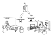
- an unmanned aerial vehicle 11e and an unmanned aircraft 23e having a camera function for capturing an aerial image and a display function for displaying a video or image transmitted from a remote place as shown in FIG. You may comprise so that it may communicate about an image.
- the unmanned aerial vehicle 11e includes a motor, an actuator, a gear group, a sensor, and the like, and is configured to be capable of autonomous flight.
- the unmanned aircraft 11e is equipped with hardware necessary for wireless communication and hardware for detecting position information such as GPS.
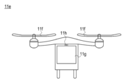
- a rotating wing 11f is provided on the upper part of the unmanned aerial vehicle 11e as shown in FIG. 12, and the unmanned aerial vehicle 11e can be moved in a vertical direction and a horizontal direction together with driving system parts such as a motor and an actuator, and hovering or the like is possible To.
- a display 11g is provided in the main body of the unmanned aerial vehicle 11e, and a camera 11h for photographing the space where the unmanned aircraft 11e is located is mounted above the display 11g. Since the unmanned aircraft 23e has the same configuration as the unmanned aircraft 11e, description thereof is omitted.
- the server 90 manages the position information of the unmanned aerial vehicles 11e and 23e, collected data, and the like. Communication between the unmanned aircraft 11e and 23e and the server 90 is performed by a relay device such as a modem, a terminal adapter, or a gateway.
- the communication network is constructed by mutually connecting various communication lines (telephone lines, ISDN lines, ADSL lines, public lines such as optical lines, dedicated lines, etc.) using the TCP / IP protocol. Commands such as activation, stop, and movement of the unmanned aircraft 11e are performed by the remote control 26.
- FIG. 13 shows a modification according to the above embodiment, and shows a case where a portable device is used to display a spatial image of a remote area for the user.
- 1st Embodiment demonstrated embodiment which displays the spatial image of relatives etc. on the patient P using the projector 23, it is not limited to this.
- a known portable terminal 23j such as a smartphone having a display function as shown in FIG. 13 may be used.
- the temperature of the space where the relative is present is measured by the thermometer 71, and the temperature is adjusted by the air conditioner 81 according to the temperature measured by the thermometer 71 in the space where the patient P is present.
- the present invention is not limited to this, and a hygrometer is installed in addition to the thermometer 71, humidity data obtained by the hygrometer is transmitted, and the air conditioner 81 adjusts the humidity in the room where the patient P is present. Also good.
- the control unit 65 of the odor generating unit 60 stores an object that can emit an odor from the data acquired by the aerial image acquiring unit 10 and an image recognition program in the ROM. Then, it may be configured to output odors based on data that can emit odors registered in advance from data recognized by image recognition and detection results of the odor sensor 51. By configuring in this way, it is possible to reproduce the odor of a remote place where a relative is present in the space where the patient P is present with higher accuracy than in the case where only the odor sensor 51 is used.
Landscapes
- Engineering & Computer Science (AREA)
- Signal Processing (AREA)
- General Engineering & Computer Science (AREA)
- Physics & Mathematics (AREA)
- Multimedia (AREA)
- Mathematical Physics (AREA)
- Mechanical Engineering (AREA)
- Chemical & Material Sciences (AREA)
- Fuzzy Systems (AREA)
- Combustion & Propulsion (AREA)
- General Physics & Mathematics (AREA)
- Theoretical Computer Science (AREA)
- Automation & Control Theory (AREA)
- Human Computer Interaction (AREA)
- Controls And Circuits For Display Device (AREA)
- Medical Treatment And Welfare Office Work (AREA)
- Transforming Electric Information Into Light Information (AREA)
- User Interface Of Digital Computer (AREA)
- Closed-Circuit Television Systems (AREA)
Abstract
利用者が、利用者のいる場所から離れた実在する場所にいるかのような体験ができる医療システムを提供する。 本発明に係る電子システム(100)は、所定の第1現実空間において視覚により認識される第1現実空間像を取得する空間像取得部(10)と、空間像取得部で取得した第1現実空間像を、第1現実空間から離れた第2現実空間において仮想的に表示する表示部(20)と、第1現実空間において第1現実空間像とは別の視覚以外の五感により認識される第1現実空間情報を取得する音声取得部(30)、匂い取得部(50)、及び周囲空気取得部(70)と、音声取得部、匂い取得部、及び周囲空気取得部で取得された第1現実空間情報を第2現実空間において再現する音声出力部(40)、匂い発生部(60)、及び周囲空気発生部(80)と、を有する。
Description
本発明は、電子システムに関する。
近年VR(ヴァーチャルリアリティ)という実在しない空間をコンピュータグラフィック技術により表示する技術の開発が進められている。上記VR技術を用いることで利用者は特定の行為を実際に経験しなくてもあたかも体験したかのような感覚を味わうことができる。VR技術に関する技術には、部屋の天井の適所に設けた光源から空間に立体を映し出す立体像投影機を備えるものがある(特許文献1参照)。
しかしながら、上記特許文献1では仮想の空間を表示しており、実在する場所にいるかのような体験ができるわけではない。
そこで本発明は、利用者が、利用者のいる場所から離れた実在する場所にいるかのような体験ができる電子システムを提供することを目的とする。
上記目的を達成する本発明に係る電子システムは、所定の第1現実空間において視覚により認識される第1現実空間像を取得する空間像取得部と、前記空間像取得部で取得した前記第1現実空間像を、前記第1現実空間から離れた第2現実空間において仮想的に表示する表示部と、前記第1現実空間において前記第1現実空間像とは別の視覚以外の五感により認識される第1現実空間情報を取得する空間情報取得部と、前記空間情報取得部で取得した前記第1現実空間情報を前記第2現実空間において再現する再現部と、を有する。
本発明に係る電子システムは、上記のように構成しているため、利用者が、利用者のいる場所から離れた実在する場所にいるかのような体験をすることができる。
<第1実施形態>
以下、添付した図面を参照しながら、本発明の実施形態を説明する。なお、以下の記載は特許請求の範囲に記載される技術的範囲や用語の意義を限定するものではない。また、図面の寸法比率は説明の都合上誇張されており、実際の比率とは異なる場合がある。
以下、添付した図面を参照しながら、本発明の実施形態を説明する。なお、以下の記載は特許請求の範囲に記載される技術的範囲や用語の意義を限定するものではない。また、図面の寸法比率は説明の都合上誇張されており、実際の比率とは異なる場合がある。
図1~図6は本発明の第1実施形態に係る電子システムの説明に供する図である。本実施形態に係る電子システム100は、一例として入院中の患者(使用者)が、入院しなければ参加する予定であった場所に行ったかのような体験を希望する場合に使用される医療システムについて説明する。
図1に示すように、電子システム100は、空間像取得部10と、表示部20と、空間情報取得部と、再現部と、を有する。空間像取得部10は所定の第1現実空間において視覚により認識される第1現実空間像を取得する。表示部20は、空間像取得部10で取得した第1現実空間像を、第1現実空間から離れた第2現実空間において仮想的に表示する。空間情報取得部は、音声取得部30、匂い取得部50、及び周囲空気取得部70を含み、第1現実空間において第1現実空間像とは別の視覚以外の五感により認識される第1現実空間情報を取得する。再現部は、音声出力部40、匂い発生部60、及び周囲空気発生部80を含み、空間情報取得部で取得した第1現実空間情報を第2現実空間において再現する。
なお、以下では第1現実空間が図2に示すように患者Pの親族の家にあたり、第2現実空間が図1に示すように患者Pの病室である場合について説明する。しかし、以下に説明する電子システム100を設置できる環境であれば、第1現実空間及び第2現実空間の場所は家や病院に限定されない。上記以外にも介護施設や保育園(保育所)、結婚式場や、当初行く予定であった旅行先のリゾート地等から選択されるいずれか2箇所、さらには離れた会議室同士等であってもよい。以下、詳述する。
(空間像取得部)
空間像取得部10は、図4に示すようにカメラ11と、スクリーン12と、プロジェクタ13と、通信部14と、制御部15と、を有する。カメラ11は、図2に示すように本実施形態において患者Pとコミュニケーション(意思疎通)する親族等がいる家の一室に設置され、親族等の空間像を撮像する。ここで、本明細書において空間像とは画像又は映像を意味する。
空間像取得部10は、図4に示すようにカメラ11と、スクリーン12と、プロジェクタ13と、通信部14と、制御部15と、を有する。カメラ11は、図2に示すように本実施形態において患者Pとコミュニケーション(意思疎通)する親族等がいる家の一室に設置され、親族等の空間像を撮像する。ここで、本明細書において空間像とは画像又は映像を意味する。
スクリーン12は、プロジェクタ13によって投影される映像を映し出すために設けられる。プロジェクタ13は、図3に示すようにいわゆるプロジェクションマッピングの技術を利用して映像を表示する。本実施形態ではスクリーン12は親族のいる部屋に設置したものとして構成している。しかし、これに限定されず、スクリーン12は、別途用意したスクリーンではなく、図2等に示すような親族等のいる部屋の壁面や、もしくは人型のスクリーン等を利用してもよい。なお、図2における空間像の投影は図3と同様であるため、図示を省略する。
プロジェクタ13は、従来公知の液晶型プロジェクタ、DLP(デジタルライトプロセッシング)プロジェクタ、LCOS(Liquid Crystal On Display)プロジェクタ等を用いることができる。
通信部14は、無線通信に用いられるハードウェア等によって構成され、インターネット回線等を用いて患者Pと遠隔地にいる親族等とのコミュニケーションを行なうために映像等のデータの送受信を行なう。制御部15は、CPU、RAM、ROM等で構成し、カメラ11から通信部14の制御を行なう。制御部15のROMにはプロジェクションマッピングに必要なプログラムが記録されており、表示部20のカメラ21によって撮影した映像をスクリーン12の形状等に応じて補正する。これにより、スクリーン12の形状に合わせて患者Pのいる病院側の映像を映し出すことができる。
(表示部)
表示部20は、図4に示すようにカメラ21と、スクリーン22と、プロジェクタ23と、通信部24と、制御部25と、リモコン26と、を有する。カメラ21は、カメラ11と同様に従来公知のカメラによって構成し、患者Pの部屋内において患者Pとその周囲等の範囲を撮像する。
表示部20は、図4に示すようにカメラ21と、スクリーン22と、プロジェクタ23と、通信部24と、制御部25と、リモコン26と、を有する。カメラ21は、カメラ11と同様に従来公知のカメラによって構成し、患者Pの部屋内において患者Pとその周囲等の範囲を撮像する。
スクリーン22は、スクリーン12と同様に図1、3に示すように患者Pのいる部屋内に設置している。なお、図1、3ではスクリーン22を便宜上平坦で模様等のないものとして図示しているが、多少の凹凸があったり、模様が形成されていてもよい。スクリーン22は、本明細書において投影面を備えた投影部に相当する。
プロジェクタ23は、プロジェクタ13と同様であるため、詳細な説明を省略する。なお、プロジェクタ23は、本明細書において第1現実空間にあたる家の映像を投影する映像出力部に相当する。
通信部24は、通信部14と同様のハードウェア等によって構成し、家等の遠隔地から送信された映像データの送受信を行なう。制御部25は、CPU、RAM、ROM等によって構成し、プロジェクタ23及び通信部24の制御を行なう。制御部25のROMには制御部15と同様にプロジェクションマッピングに必要なプログラムが記録されており、カメラ21によって撮像したスクリーン22の形状等に応じて空間像取得部10から取得した映像を補正する。
制御部25のROMに記憶されたプロジェクションマッピング用のプログラムは、本明細書において投影面の性状に合わせて映像を補正する補正部にあたる。リモコン26は従来公知の構成と同様であり、ボタンや通信部等の構成を備え、表示部20の構成の起動のオン、オフを切り替える信号を送出できるように構成している。
(音声取得部)
音声取得部30は、図4に示すようにマイク31と、スピーカー32と、通信部33と、制御部34と、を有する。マイク31は、図2に示すように親族等の家の一室に設置され、親族等から発せられる音声や周囲の音声を取得する。スピーカー32は、親族等の家の部屋の一室に設置され、隔地である病院で取得された患者Pや周囲の音声を出力する。
音声取得部30は、図4に示すようにマイク31と、スピーカー32と、通信部33と、制御部34と、を有する。マイク31は、図2に示すように親族等の家の一室に設置され、親族等から発せられる音声や周囲の音声を取得する。スピーカー32は、親族等の家の部屋の一室に設置され、隔地である病院で取得された患者Pや周囲の音声を出力する。
通信部33は、通信部14と同様に構成され、患者Pのいる病院等に親族の音声を送受信する。制御部34は、CPU、RAM、ROM等によって構成し、マイク31から通信部33を制御する。
(音声出力部)
音声出力部40は、図4に示すようにスピーカー41と、マイク42と、通信部43と、制御部44と、を有する。スピーカー41は患者Pのいる病室に設置され、通信部33から送信された親族等の音声及び周囲の音声を出力する。マイク42は、患者Pのいる病院の一室に設置され、患者Pが発する音声及び周囲の音声を取得する。
音声出力部40は、図4に示すようにスピーカー41と、マイク42と、通信部43と、制御部44と、を有する。スピーカー41は患者Pのいる病室に設置され、通信部33から送信された親族等の音声及び周囲の音声を出力する。マイク42は、患者Pのいる病院の一室に設置され、患者Pが発する音声及び周囲の音声を取得する。
通信部43は、通信部14と同様に構成され、通信部33と音声に関するデータの送受信を行なう。制御部44は、CPU、RAM、ROM等にで構成され、スピーカー41から通信部43を制御する。
(匂い取得部)
匂い取得部50は、図4に示すように匂いセンサ51と、通信部52と、制御部53と、を有する。匂いセンサ51は、図2に示すように家等の親族のいる第1現実空間にあたる家の部屋内の匂いを検出する検出部にあたる。匂いセンサ51は、取得する匂いに応じて複数個設置することができる。
匂い取得部50は、図4に示すように匂いセンサ51と、通信部52と、制御部53と、を有する。匂いセンサ51は、図2に示すように家等の親族のいる第1現実空間にあたる家の部屋内の匂いを検出する検出部にあたる。匂いセンサ51は、取得する匂いに応じて複数個設置することができる。
匂いセンサ51は、電子システム100の設置される場所に応じて例えばリビングや寝室であればコーヒーやお茶等の匂いを検出するセンサ、家具等の匂いを検出するセンサを設置することができる。なお、図2では一例として親族等のいる部屋にコーヒー等を用意している。
通信部52は、通信部14と同様のハードウェアによって構成され、匂いセンサ51によって取得された匂いに関する情報を匂い発生部60に送信する。制御部53は、匂いセンサ51及び通信部52を制御する。
(匂い発生部)
匂い発生部60は、図4に示すようにカートリッジ61と、配合部62と、発生器63と、通信部64と、制御部65と、を有する。カートリッジ61は、複数用意され、親族等のように患者Pと対話する親族のいる部屋の匂いを再現するために、例えば飲食物の匂いや家具のような匂いをそれぞれ保有している。
匂い発生部60は、図4に示すようにカートリッジ61と、配合部62と、発生器63と、通信部64と、制御部65と、を有する。カートリッジ61は、複数用意され、親族等のように患者Pと対話する親族のいる部屋の匂いを再現するために、例えば飲食物の匂いや家具のような匂いをそれぞれ保有している。
配合部62は、通信部64から取得された情報に基づいて実際の家と同様の匂いを再現するためにカートリッジ61に収容された複数の匂いを配合する。発生器63はファン等によって構成し、配合部62によって配合された匂いを患者Pに向けて送風する。通信部64は、遠隔地の匂い取得部50の通信部52と通信し、匂い取得部50によって測定された匂い成分に関するデータを取得する。制御部65は、CPU、RAM、ROM等によって構成し、配合部62から通信部64までを制御する。
(周囲空気取得部)
周囲空気取得部70は、図4に示すように温度計71と、風速計72と、通信部73と、制御部74と、を有する。温度計71は、公知のデジタル温度計等によって構成し、図2に示すように家において親族等のいる部屋の温度をデジタルデータとして取得する。風速計72は、公知の風速計によって構成し、家における親族等のいる部屋の風速等を測定する。温度計71と風速計72とを利用することによって、親族のいる部屋内がエアコン等を用いて温度調整している場合、患者Pのいる空間の温度や風を親族等のいる部屋と同様に調整することができる。
周囲空気取得部70は、図4に示すように温度計71と、風速計72と、通信部73と、制御部74と、を有する。温度計71は、公知のデジタル温度計等によって構成し、図2に示すように家において親族等のいる部屋の温度をデジタルデータとして取得する。風速計72は、公知の風速計によって構成し、家における親族等のいる部屋の風速等を測定する。温度計71と風速計72とを利用することによって、親族のいる部屋内がエアコン等を用いて温度調整している場合、患者Pのいる空間の温度や風を親族等のいる部屋と同様に調整することができる。
温度計71は本明細書において第1現実空間にあたる家において親族等のいる部屋内の周囲の温度を測定する測定部にあたる。風速計72は第1現実空間にあたる親族等のいる部屋内の風速を測定する他の測定部にあたる。
通信部73は、温度計71及び風速計72によって取得されたデータを患者Pの周囲空気発生部80の通信部82に送信する。制御部74は、上記と同様にCPU,RAM、ROM等によって構成し、温度計71から通信部73までを制御する。
(周囲空気発生部)
周囲空気発生部80は、図4に示すようにエアコン81と、通信部82と、制御部83と、を有する。エアコン81は、公知の圧縮機、蒸発器、凝縮器、膨張弁等によって構成し、患者Pのいる部屋内の温度及び風速を調整する。エアコン81は本明細書において温度計71によって測定された温度に合わせて第2現実空間にあたる患者Pのいる病院の一室の温度を調整する調製部にあたる。また、エアコン81は風速計72によって測定された風速の風を第2現実空間において出力する送風部にあたる。
周囲空気発生部80は、図4に示すようにエアコン81と、通信部82と、制御部83と、を有する。エアコン81は、公知の圧縮機、蒸発器、凝縮器、膨張弁等によって構成し、患者Pのいる部屋内の温度及び風速を調整する。エアコン81は本明細書において温度計71によって測定された温度に合わせて第2現実空間にあたる患者Pのいる病院の一室の温度を調整する調製部にあたる。また、エアコン81は風速計72によって測定された風速の風を第2現実空間において出力する送風部にあたる。
通信部82は、周囲空気取得部70の通信部73から親族等のいる部屋の温度や風速に関するデータを受信する。制御部83は、エアコン81及び通信部82を制御する。
次に本実施形態に係る電子システム100を用いた遠隔地間の対話について説明する。図5は本実施形態に係る電子システムにおける情報のやりとりを示すシーケンス図である。図6は本実施形態に係る電子システムを用いた隔地間の対話について説明するフローチャートである。
図6を参照して本実施形態に係る電子システム100の使用について説明すれば、まず患者Pがリモコン26のボタンを押下により隔地である家との接続を要求しているかが判断される(ST1)。接続要求があった場合(ST1:YES)、空間像取得部10のカメラ11によって家側の撮像範囲内の映像が取得される(ST2)。次に、通信部14、24を介して撮像された映像データが病院側に送信される(ST3)。映像データは、表示部20のプロジェクタ23によってスクリーン22に投影され、患者Pは映像を視認できる状態になる(ST4)。
また、空間像取得部10から映像データが送信されると、通信部14によって音声取得部30、匂い取得部50、及び周囲空気取得部70に映像データの出力要求があったことが通知される(ST5)。音声取得部30、匂い取得部50、及び周囲空気取得部70において上記通知が行われると、音声取得部30、匂い取得部50、及び周囲空気取得部70は、空間像取得部10とほぼ同じ範囲内において周囲の音声、匂い、温度、風速データを取得する(ST6)。
音声取得部30、匂い取得部50、及び周囲空気取得部70によって取得されたデータは通信部33、52、73によって通信部43、64、82に送信される(ST7)。送信された空間情報はそれぞれ音声出力部40のスピーカー41、匂い発生部60の発生器63、及び周囲空気発生部80のエアコン81によって患者Pの周囲に出力される(ST8)。図6のST2における映像データの取得からST8における空間情報の出力は患者Pのリモコン26から第1現実空間にあたる家との接続に対する遮断要求がない限り(ST9:NO)継続される。
患者Pからリモコン26による家との接続の遮断要求がない限り、親族はカメラ11、スクリーン12、プロジェクタ13、マイク31、スピーカー32を用いて患者Pと対話することができる。
患者Pからリモコン26により家との接続の遮断要求があった場合(ST9:YES)、表示部20、音声出力部40、匂い発生部60及び周囲空気発生部80からの空間像及び空間情報の出力を停止する。
次に、上記電子システム100における情報のやりとりについて図5を参照しながら、説明する。
電子システム100では、まず患者Pがリモコン26のボタンを押下すると、表示部20の制御部25によって通信部24から空間像取得部10の通信部14に映像データの出力を要求する信号が送信される(S1)。空間像取得部10の通信部14は上記信号を受信すると、カメラ11を動作させてカメラ11の撮像範囲にいる親族や周囲の背景を撮像し、映像データを取得する(S2)。
次に通信部14はカメラ11が撮像した映像データを表示部20の通信部24に送信する(S3)。表示部20の通信部24が映像データを取得すると、プロジェクタ23によって図3に示すようにスクリーン22に家の映像が出力される(S4)。また、空間像取得部10の通信部14は、上記信号を受信した際に出力要求がなされたことを通知する信号を音声取得部30の通信部33、匂い取得部50の通信部52、及び周囲空気取得部70の通信部73に送信する(S5)。
音声取得部30の通信部33が通信部14から信号を受信すると、制御部34はマイク31を制御して取得領域である周囲数mの範囲にいる親族や周囲の音声を取得する(S6)。マイク31によって取得された音声データは通信部33を通じて音声出力部40の通信部43に送信され(S7)、スピーカー41において送信された音声データが患者Pに向けて出力される(S8)。
一方、匂い取得部50の通信部52において通信部14からの信号が受信されると、匂いセンサ51によって周囲数m内の範囲内の匂いデータが取得される(S6)。取得されたデータは通信部52を通じて匂い発生部60の通信部64にて送信される(S7)。通信部64にて受信されたデータは制御部65によってカートリッジ61の中から必要な匂い成分が選択され、配合部62において配合され、患者Pの周囲に出力される(S8)。
周囲空気取得部70の通信部73が通信部14から信号を受信すると、制御部74は温度計71及び風速計72を起動させ、周囲数mの範囲内の温度及び風速を測定する(S6)。温度計71及び風速計72によって測定されたデータは通信部73によって周囲空気発生部80の通信部82に送信される(S7)。周囲空気発生部80のエアコン81は受信した情報に基づいて患者Pのいる部屋内の温度、風速を調整する(S8)。
反対に、患者Pが遠隔地である家との接続の遮断を要求する場合、表示部20のリモコン26のボタンを押下する(S9)。リモコン26のボタンが押下されると、表示部20では制御部25がプロジェクタ23の出力を停止させ、スクリーン22への映像の投影を停止させる(S10)。通信部14において通信部24からの信号が受信されると、制御部15はカメラ11による映像データの取得を停止させる(S11)。
また、リモコン26のボタンが押下されると、通信部24は通信部43、64、73に出力停止信号が送信されたことを通知する(S12)。通信部43に信号が受信されると制御部44により音声の出力が停止される(S13)。また、通信部64において通信部14からの信号が受信されると、制御部65は配合部62及び発生器63の動作を停止させる(S13)。通信部82において通信部14からの信号が受信されると、制御部83はエアコン81の動作を停止させる(S13)。
通信部43において通信部24からの信号を受信すると、通信部43は通信部33に音声データの取得停止要求を通知する(S14)。制御部34はマイク31を制御して家の部屋内における音声データの取得を停止する(S15)。
通信部64において通信部24からの信号を受信すると、通信部64は通信部52に匂いデータの取得停止要求を通知する(S14)。これを受け、制御部55は匂いセンサ51の動作を停止させる(S15)。
通信部82は通信部24から信号を受信すると、通信部73に周囲空気データの取得停止要求を通知する(S14)。これを受け、制御部74は温度計71及び風速計72による温度データ及び風速データの取得を停止する(S15)。
上記のように本実施形態の電子システム100は、空間像取得部10と、表示部20と、空間情報取得部と、再現部と、を有するように構成している。空間像取得部10は所定の第1現実空間にあたる家において視覚により認識される空間像を取得する。表示部20は空間像取得部10で取得した第1現実空間像を第1現実空間である家から離れた第2現実空間である病院において仮想的に表示する。
空間情報取得部は、音声取得部30、匂い取得部50、及び周囲空気取得部70によって構成し、第1現実空間である家において第1現実空間像とは別の視覚以外の五感により認識される空間情報を取得する。再現部は音声出力部40、匂い発生部60及び周囲空気発生部80によって構成し、空間情報取得部にて取得した第1現実空間情報である家の第1現実空間情報を患者Pのいる病院において再現する。
このように構成することによって、患者Pは体の具合が急に悪くなったりすることで当初予定していた学校の行事や旅行に行けなくなった場合等に、患者Pのいる場所から離れた家等にあたかもいるかのような体験をすることができる。このように電子システム100によれば、患者Pは隔地にいる親族等と同じ空間を共有しているかのような錯覚を体験することができる。
また、表示部20は第1現実空間にあたる家の空間像を投影するプロジェクタ23と、プロジェクタ23から出力された空間像を表示するスクリーン22と、スクリーン22の性状に合わせて空間像を補正するプログラムを制御部25のROMに記憶する。そのため、患者Pのいる部屋内に設置されたスクリーン22の性状に拘束されることなく家側(第1現実空間)の空間像を映し出すことができ、臨場感を向上させることができる。
また、匂い取得部50は、第1現実空間にあたる家の部屋の匂いを検出する匂いセンサ51を備え、匂い発生部60は匂いセンサ51によって検出された匂いに対応する匂いを患者Pの病院の一室において出力するように構成している。そのため、視覚や聴覚だけでなく、嗅覚をもって、より臨場感のある状況を再現でき、より使用者の満足度を向上させることができる。
また、周囲空気取得部70は第1現実空間にあたる家の部屋内の周囲の温度を測定する温度計71を備え、周囲空気発生部80は温度計71によって測定した温度に合わせて患者Pのいる病院の一室の周囲の温度を調整するエアコン81を備える。そのため、上記と同様に視覚や聴覚だけでなく触覚に含まれる温度感覚等も現地に近似させることによって患者Pにより臨場感を感じさせることができる。
また、周囲空気取得部70は第1現実空間である家の部屋の周囲の風速を測定する風速計72を備え、周囲空気発生部80は風速計72によって測定された風速の風を患者Pのいる病院の一室において出力するエアコン81を備えるように構成している。そのため、上記と同様に視覚や聴覚だけでなく触覚も動員して患者Pに現地に行ったかのような臨場感を体験させることができる。
<第2実施形態>
図7は第2実施形態に係る電子システムを示し、第2現実空間にあたる使用者のいる場所を示す図である。図8は第2実施形態に係る電子システムを示すブロック図である。第1実施形態では表示部20がスクリーン22とプロジェクタ23を備えることを説明したが、以下のような構成を採用することもできる。なお、第2実施形態では表示部のみの構成が異なり、その他は第1実施形態と同様であるため、共通する構成の説明を省略する。
図7は第2実施形態に係る電子システムを示し、第2現実空間にあたる使用者のいる場所を示す図である。図8は第2実施形態に係る電子システムを示すブロック図である。第1実施形態では表示部20がスクリーン22とプロジェクタ23を備えることを説明したが、以下のような構成を採用することもできる。なお、第2実施形態では表示部のみの構成が異なり、その他は第1実施形態と同様であるため、共通する構成の説明を省略する。
第2実施形態に係る電子システム100aの表示部20aは、図8に示すようにカメラ21と、設置台22aと、画像生成部23aと、通信部24と、制御部25と、リモコン26と、を有する。カメラ21、通信部24、制御部25、及びリモコン26は第1実施形態と同様であるため、説明を省略する。
設置台22aは、患者Pのいる空間において特にカメラ21や画像生成部23aの撮影領域範囲内に設置された金属等からなる土台であり、本実施形態では患者Pのいる空間の地面に設置される。設置台22aは、カメラ21や画像生成部23a等の電子機器を設置する。設置台22aは、本実施形態において設置部に相当する。
画像生成部23aは、患者Pに対向して設置され、半導体レーザー等を照射する照射装置や照射されたレーザーを患者Pの網膜に向けて反射させるガルバノミラー等を含む。画像生成部23aは、上記構成により空間像取得部10において撮影された親族等の映像信号となるようにレーザーを変調し、患者Pの網膜において走査させながら出射することによって患者Pの網膜で空間像を生成する。
ここで、画像生成部23aにおける「対向して」とは、画像生成部23aが患者Pにおいて目的とする対象部位が撮影できるように位置及び/又は向きが調整されることを意味する。
第2実施形態における画像生成部23aは第1実施形態におけるプロジェクタ23にあたり、電子システム100aの動作は第1実施形態と同様であるため、シーケンス図やフローチャートを用いた説明を省略する。
以上のように第2実施形態の電子システム100aの表示部20aは、設置台22aと画像生成部23aと、を備えるように構成している。設置台22aは、患者Pのいる病院の一室に設置され、画像生成部23aは設置台22aに設置されるとともに患者Pの網膜において親族等のいる家において撮影された第1現実空間像を生成するレーザーを生成する。
そのため、患者Pは遠隔地からの映像を認識するためにメガネ等の装着タイプの器具を装着する必要がない。よって、メガネ型の器具の長時間の装着によって装着部位である耳等に褥瘡のような症状が発生することを防止できる。また、病院等では同じ部屋等における感染症の拡大を防止することができる。
<第3実施形態> 図9は第3実施形態に係る電子システムを示し、第2現実空間にあたる使用者のいる場所を示す図である。図10は第3実施形態に係る電子システムを示すブロック図である。第1実施形態では表示部20がプロジェクタ23とスクリーン22を使用して映像を投影し、第2実施形態では画像生成部23aが患者Pの網膜に家の空間像を生成すると説明した。しかし、表示部は以下のように構成することもできる。なお、第3実施形態では表示部の構成のみが異なり、その他の構成は第1実施形態や第2実施形態と同様であるため、共通する説明を省略する。
第3実施形態に係る電子システム100bの表示部20bは、図10に示すようにカメラ21と、ゴーグル23bと、通信部24と、制御部25と、リモコン26と、を有する。カメラ21、通信部24、制御部25、及びリモコン26は第1実施形態と同様であるため、共通する説明を省略する。
ゴーグル23bは、メガネタイプの器具であり、図9に示すように映像を投影しメガネにおけるレンズの部位にあたる投影面23cと、ディスプレイ面の左右両端から患者Pの耳等に延在し、耳等の身体の部位にかけられる装着部23dを備える。制御部25は、カメラ11によって撮影された映像データを画像処理し、投影面に投影する。装着部は本実施形態においてゴムバンドによって構成しているが、ゴーグル23bを患者Pに装着できればよく、上記以外にもメガネのアーム(テンプル)によって構成してもよい。ゴーグル23bは上記のように構成することによって、ゴーグル23bを装着した患者Pはゴーグル23bの投影面23cから親族等のいる家の部屋の空間像等を認識することができる。
第3実施形態におけるゴーグル23bは第1実施形態におけるプロジェクタ23及び第2実施形態における画像生成部23aにあたり、電子システム100bの動作は第1実施形態と同様であるため、シーケンス図やフローチャートを用いた説明を省略する。
以上のように第3実施形態の電子システム100bの表示部20bは、第1現実空間像を投影する投影面23cと、投影面23cの両端から延在し第2現実空間にあたる病院の一室にいる患者Pの耳等に装着される装着部23dと、を備えるように構成している。そのため、近年ゲーム業界等において普及しているゴーグルタイプのヘッドマウントディスプレイのように比較的手軽に親族等のいる第1現実空間像を認識することができる。
なお、本発明は上述した実施形態にのみ限定されることなく、特許請求の範囲において種々の変更が可能である。図11は上記実施形態の変形例を示す図、図12は図11に表れる無人航空機を示す図である。上記では親族等の撮影をカメラ11によって行い、プロジェクタ23、画像生成部23a、又はゴーグル23bによって患者Pに表示する実施形態について説明したが、これに限定されない。
上記以外にも図11に示すように空間像を撮影するカメラ機能と隔地から送信された映像又は画像を表示する表示機能とを備えた無人航空機11e及び無人航空機23eによって、家と病院との空間像について通信を行うように構成してもよい。
無人航空機11eは、モーター、アクチュエーター、ギヤ群、センサ等を備えて自律飛行可能に構成され、無線通信に必要なハードウェア、GPS等の位置情報を検出するハードウェアを搭載する。
無人航空機11eの上部には図12に示すように回転翼11fが設けられ、モーターやアクチュエーター等の駆動系部品と共に無人航空機11eを垂直方向、水平方向への移動可能にし、また、ホバリング等を可能にする。無人航空機11eの本体部にはディスプレイ11gが設けられ、ディスプレイ11gの上方には無人航空機11eのいる空間を撮影するカメラ11hが搭載される。無人航空機23eは無人航空機11eと同様の構成であるため、説明を省略する。
サーバ90は無人航空機11e、23eの位置情報や収集したデータ等の管理を行なう。無人航空機11e、23eとサーバ90との通信はモデム、ターミナルアダプタ、ゲートウェイ等の中継装置によって行われる。通信ネットワークはTCP/IPプロトコルを用いて種々の通信回線(電話回線、ISDN回線、ADSL回線、光回線などの公衆回線、専用回線等)を相互に接続して構築される。無人航空機11eへの起動や停止、移動等の命令はリモコン26によって行なわれる。
このように構成することによっても、患者Pのいる病院から離れた家にいるかのような臨場感を体験させることができる。
図13は上記実施形態に係る変形例を示し、使用者に対する隔地の空間像の表示に携帯デバイスを利用する場合を示す図である。第1実施形態ではプロジェクタ23を用いて患者Pに親族等の空間像を表示する実施形態について説明したが、これに限定されない。上記以外にもプロジェクタ23の代わりに、図13に示すようにディスプレイ機能を備えたスマートフォン等の公知の携帯端末23jを利用してもよい。
また、第1実施形態では温度計71によって親族等のいる空間の温度を測定し、患者Pのいる空間において温度計71で測定した温度に合わせてエアコン81により温度を調整する実施形態について説明した。しかし、これに限定されず、温度計71に加えて湿度計を設置し、湿度計によって得られた湿度データを送信してエアコン81により患者Pのいる室内の湿度を調整するように構成してもよい。
また、第1実施形態等では匂い発生部60が匂い取得部50によって検出された匂いを発生する実施形態について説明したが、これに限定されない。匂い発生部60の制御部65には空間像取得部10により取得したデータから匂いを発し得る物体及び画像認識のプログラムをROMに記憶する。そして、画像認識により認識されたデータから予め登録された匂いを発しうるデータと匂いセンサ51の検出結果に基づいて匂いの出力を行うように構成してもよい。このように構成することによって、匂いセンサ51のみによる場合よりもさらに精度よく患者Pのいる空間において親族等のいる隔地の匂いを再現することができる。
本出願は、2017年2月2日に出願された日本国特許出願第2017-017930号に基づいており、その開示内容は、参照により全体として引用されている。
10 空間像取得部、
20、20a、20b 表示部、
22 スクリーン(投影部)、
22a 設置台(設置部)、
23 プロジェクタ(映像出力部)、
23a 画像生成部、
23b ゴーグル、
23c 投影面、
23d 装着部、
25 制御部(補正部)、
30 音声取得部、
40 音声出力部、
50 匂い取得部、
51 匂いセンサ(検出部)、
60 匂い発生部、
70 周囲空気取得部、
71 温度計(測定部)、
72 風速計(他の測定部)、
80 周囲空気発生部、
81 エアコン(送風部、調整部)、
90 サーバ、
100、100a、100b 電子システム。
20、20a、20b 表示部、
22 スクリーン(投影部)、
22a 設置台(設置部)、
23 プロジェクタ(映像出力部)、
23a 画像生成部、
23b ゴーグル、
23c 投影面、
23d 装着部、
25 制御部(補正部)、
30 音声取得部、
40 音声出力部、
50 匂い取得部、
51 匂いセンサ(検出部)、
60 匂い発生部、
70 周囲空気取得部、
71 温度計(測定部)、
72 風速計(他の測定部)、
80 周囲空気発生部、
81 エアコン(送風部、調整部)、
90 サーバ、
100、100a、100b 電子システム。
Claims (7)
- 所定の第1現実空間において視覚により認識される第1現実空間像を取得する空間像取得部と、
前記空間像取得部で取得した前記第1現実空間像を、前記第1現実空間から離れた第2現実空間において仮想的に表示する表示部と、
前記第1現実空間において前記第1現実空間像とは別の視覚以外の五感により認識される第1現実空間情報を取得する空間情報取得部と、
前記空間情報取得部で取得した前記第1現実空間情報を前記第2現実空間において再現する再現部と、を有する電子システム。 - 前記表示部は、前記第1現実空間像を投影する映像出力部と、前記映像出力部から出力された前記第1現実空間像を表示する投影面を備えた投影部と、前記投影面の性状に合わせて前記第1現実空間像を補正する補正部と、を備えた請求項1に記載の電子システム。
- 前記表示部は、前記第2現実空間に設置された設置部と、前記設置部に設置されるとともに前記第2現実空間にいる人物の網膜において前記第1現実空間像を生成するレーザーを生成する画像生成部と、を有する、請求項1に記載の電子システム。
- 前記表示部は、前記第1現実空間像を投影する投影面と、前記投影面の両端から延在し前記第2現実空間にいる人物の身体の一部に装着される装着部と、を備える、請求項1に記載の電子システム。
- 前記空間情報取得部は、前記第1現実空間の周囲の匂いを検出する検出部を備え、
前記再現部は、前記検出部によって検出された前記匂いに相当する物質を前記第2現実空間に出力する、請求項1~4のいずれか1項に記載の電子システム。 - 前記空間情報取得部は、前記第1現実空間の周囲の温度及び/又は湿度を測定する測定部を備え、
前記再現部は、前記測定部による測定結果に合わせて前記第2現実空間の周囲の温度及び/又は湿度を調整する調製部を備える、請求項1~5のいずれか1項に記載の電子システム。 - 前記空間情報取得部は、前記第1現実空間の周囲の風速を測定する他の測定部を備え、
前記再現部は、前記他の測定部によって測定された風速の風を前記第2現実空間において出力する送風部を備える、請求項1~6のいずれか1項に記載の電子システム。
Priority Applications (1)
| Application Number | Priority Date | Filing Date | Title |
|---|---|---|---|
| US16/506,795 US20190331359A1 (en) | 2017-02-02 | 2019-07-09 | Electronic real-life simulation treatment system |
Applications Claiming Priority (2)
| Application Number | Priority Date | Filing Date | Title |
|---|---|---|---|
| JP2017017930A JP2020057029A (ja) | 2017-02-02 | 2017-02-02 | 電子システム |
| JP2017-017930 | 2017-08-22 |
Related Child Applications (1)
| Application Number | Title | Priority Date | Filing Date |
|---|---|---|---|
| US16/506,795 Continuation US20190331359A1 (en) | 2017-02-02 | 2019-07-09 | Electronic real-life simulation treatment system |
Publications (1)
| Publication Number | Publication Date |
|---|---|
| WO2018143256A1 true WO2018143256A1 (ja) | 2018-08-09 |
Family
ID=63039743
Family Applications (1)
| Application Number | Title | Priority Date | Filing Date |
|---|---|---|---|
| PCT/JP2018/003169 Ceased WO2018143256A1 (ja) | 2017-02-02 | 2018-01-31 | 電子システム |
Country Status (3)
| Country | Link |
|---|---|
| US (1) | US20190331359A1 (ja) |
| JP (1) | JP2020057029A (ja) |
| WO (1) | WO2018143256A1 (ja) |
Cited By (13)
| Publication number | Priority date | Publication date | Assignee | Title |
|---|---|---|---|---|
| CN109114769A (zh) * | 2018-09-12 | 2019-01-01 | 珠海格力电器股份有限公司 | 空调出风模式控制方法、系统以及装置 |
| WO2022097758A1 (ja) * | 2020-11-05 | 2022-05-12 | テルモ株式会社 | 生体情報管理システム |
| US11636870B2 (en) | 2020-08-20 | 2023-04-25 | Denso International America, Inc. | Smoking cessation systems and methods |
| US11760170B2 (en) | 2020-08-20 | 2023-09-19 | Denso International America, Inc. | Olfaction sensor preservation systems and methods |
| US11760169B2 (en) | 2020-08-20 | 2023-09-19 | Denso International America, Inc. | Particulate control systems and methods for olfaction sensors |
| US11813926B2 (en) | 2020-08-20 | 2023-11-14 | Denso International America, Inc. | Binding agent and olfaction sensor |
| US11828210B2 (en) | 2020-08-20 | 2023-11-28 | Denso International America, Inc. | Diagnostic systems and methods of vehicles using olfaction |
| US11881093B2 (en) | 2020-08-20 | 2024-01-23 | Denso International America, Inc. | Systems and methods for identifying smoking in vehicles |
| US11932080B2 (en) | 2020-08-20 | 2024-03-19 | Denso International America, Inc. | Diagnostic and recirculation control systems and methods |
| US12017506B2 (en) | 2020-08-20 | 2024-06-25 | Denso International America, Inc. | Passenger cabin air control systems and methods |
| US12251991B2 (en) | 2020-08-20 | 2025-03-18 | Denso International America, Inc. | Humidity control for olfaction sensors |
| US12269315B2 (en) | 2020-08-20 | 2025-04-08 | Denso International America, Inc. | Systems and methods for measuring and managing odor brought into rental vehicles |
| US12377711B2 (en) | 2020-08-20 | 2025-08-05 | Denso International America, Inc. | Vehicle feature control systems and methods based on smoking |
Families Citing this family (2)
| Publication number | Priority date | Publication date | Assignee | Title |
|---|---|---|---|---|
| US11087552B2 (en) * | 2019-11-26 | 2021-08-10 | Rufina Shatkina | Collaborative on-demand experiences |
| CN112378053A (zh) * | 2020-11-02 | 2021-02-19 | 珠海格力电器股份有限公司 | 一种空调控制方法、装置、存储介质及空调 |
Citations (4)
| Publication number | Priority date | Publication date | Assignee | Title |
|---|---|---|---|---|
| WO2009157187A1 (ja) * | 2008-06-23 | 2009-12-30 | Murthy Prakash Sreedhar | 化学物質に関連した情報を取り扱うためのシステム |
| JP2014164003A (ja) * | 2013-02-21 | 2014-09-08 | Nec Networks & System Integration Corp | 仮想屋内空間表示装置 |
| JP2015032085A (ja) * | 2013-08-01 | 2015-02-16 | セイコーエプソン株式会社 | 表示装置、頭部装着型表示装置、表示システムおよび表示装置の制御方法 |
| WO2016072120A1 (ja) * | 2014-11-07 | 2016-05-12 | ソニー株式会社 | 情報処理システム、制御方法、および記憶媒体 |
-
2017
- 2017-02-02 JP JP2017017930A patent/JP2020057029A/ja active Pending
-
2018
- 2018-01-31 WO PCT/JP2018/003169 patent/WO2018143256A1/ja not_active Ceased
-
2019
- 2019-07-09 US US16/506,795 patent/US20190331359A1/en not_active Abandoned
Patent Citations (4)
| Publication number | Priority date | Publication date | Assignee | Title |
|---|---|---|---|---|
| WO2009157187A1 (ja) * | 2008-06-23 | 2009-12-30 | Murthy Prakash Sreedhar | 化学物質に関連した情報を取り扱うためのシステム |
| JP2014164003A (ja) * | 2013-02-21 | 2014-09-08 | Nec Networks & System Integration Corp | 仮想屋内空間表示装置 |
| JP2015032085A (ja) * | 2013-08-01 | 2015-02-16 | セイコーエプソン株式会社 | 表示装置、頭部装着型表示装置、表示システムおよび表示装置の制御方法 |
| WO2016072120A1 (ja) * | 2014-11-07 | 2016-05-12 | ソニー株式会社 | 情報処理システム、制御方法、および記憶媒体 |
Cited By (13)
| Publication number | Priority date | Publication date | Assignee | Title |
|---|---|---|---|---|
| CN109114769A (zh) * | 2018-09-12 | 2019-01-01 | 珠海格力电器股份有限公司 | 空调出风模式控制方法、系统以及装置 |
| US11828210B2 (en) | 2020-08-20 | 2023-11-28 | Denso International America, Inc. | Diagnostic systems and methods of vehicles using olfaction |
| US11636870B2 (en) | 2020-08-20 | 2023-04-25 | Denso International America, Inc. | Smoking cessation systems and methods |
| US11760170B2 (en) | 2020-08-20 | 2023-09-19 | Denso International America, Inc. | Olfaction sensor preservation systems and methods |
| US11760169B2 (en) | 2020-08-20 | 2023-09-19 | Denso International America, Inc. | Particulate control systems and methods for olfaction sensors |
| US11813926B2 (en) | 2020-08-20 | 2023-11-14 | Denso International America, Inc. | Binding agent and olfaction sensor |
| US11881093B2 (en) | 2020-08-20 | 2024-01-23 | Denso International America, Inc. | Systems and methods for identifying smoking in vehicles |
| US11932080B2 (en) | 2020-08-20 | 2024-03-19 | Denso International America, Inc. | Diagnostic and recirculation control systems and methods |
| US12017506B2 (en) | 2020-08-20 | 2024-06-25 | Denso International America, Inc. | Passenger cabin air control systems and methods |
| US12251991B2 (en) | 2020-08-20 | 2025-03-18 | Denso International America, Inc. | Humidity control for olfaction sensors |
| US12269315B2 (en) | 2020-08-20 | 2025-04-08 | Denso International America, Inc. | Systems and methods for measuring and managing odor brought into rental vehicles |
| US12377711B2 (en) | 2020-08-20 | 2025-08-05 | Denso International America, Inc. | Vehicle feature control systems and methods based on smoking |
| WO2022097758A1 (ja) * | 2020-11-05 | 2022-05-12 | テルモ株式会社 | 生体情報管理システム |
Also Published As
| Publication number | Publication date |
|---|---|
| JP2020057029A (ja) | 2020-04-09 |
| US20190331359A1 (en) | 2019-10-31 |
Similar Documents
| Publication | Publication Date | Title |
|---|---|---|
| US20190331359A1 (en) | Electronic real-life simulation treatment system | |
| US11245883B2 (en) | Method for augmenting surfaces in a space with visual content | |
| CN113812171B (zh) | 结合房间模式的局部效果的声学滤波器的确定 | |
| RU2621644C2 (ru) | Мир массового одновременного удаленного цифрового присутствия | |
| JP5934368B2 (ja) | 可搬装置、仮想現実システムおよび方法 | |
| JP2022191313A (ja) | 双方向性拡張または仮想現実装置 | |
| JP2916142B1 (ja) | 全周球面スクリーン投影装置 | |
| KR20210141707A (ko) | 매핑 서버를 사용하는 헤드셋에 대한 음향 파라미터들의 결정 | |
| CN104429064A (zh) | 图像生成装置及图像生成方法 | |
| US20190045125A1 (en) | Virtual reality video processing | |
| US12413808B2 (en) | Video display system, information processing method, and recording medium | |
| JP7256491B2 (ja) | 映像伝送システム、映像伝送装置、および、映像伝送プログラム | |
| JP2018163461A (ja) | 情報処理装置、および情報処理方法、並びにプログラム | |
| CN113870213A (zh) | 图像显示方法、装置、存储介质以及电子设备 | |
| JPWO2019097639A1 (ja) | 情報処理装置および画像生成方法 | |
| JP6599183B2 (ja) | 画像表示システム及び画像表示方法 | |
| JP2004056161A (ja) | マルチメディア通信システム | |
| US11212485B2 (en) | Transparency system for commonplace camera | |
| KR20180010891A (ko) | Vr기기를 통한 360도 오페라 영상 제공방법 | |
| EP3493028A1 (en) | Devices, systems and methods for enhancing content viewer experience using augmented reality | |
| TW201135583A (en) | Telescopic observation method for virtual and augmented reality and apparatus thereof | |
| JP2019140530A (ja) | サーバ装置、表示装置、映像表示システム、及び映像表示方法 | |
| JP7614765B2 (ja) | コンテンツ提示装置、及びプログラム | |
| WO2017043661A1 (ja) | 画像表示システム及び画像表示方法 | |
| CN114779926A (zh) | 基于增强现实的博物馆交互式眼镜 |
Legal Events
| Date | Code | Title | Description |
|---|---|---|---|
| 121 | Ep: the epo has been informed by wipo that ep was designated in this application |
Ref document number: 18748267 Country of ref document: EP Kind code of ref document: A1 |
|
| NENP | Non-entry into the national phase |
Ref country code: DE |
|
| NENP | Non-entry into the national phase |
Ref country code: JP |
|
| 122 | Ep: pct application non-entry in european phase |
Ref document number: 18748267 Country of ref document: EP Kind code of ref document: A1 |