WO2018142806A1 - Head-up display device - Google Patents
Head-up display device Download PDFInfo
- Publication number
- WO2018142806A1 WO2018142806A1 PCT/JP2017/046323 JP2017046323W WO2018142806A1 WO 2018142806 A1 WO2018142806 A1 WO 2018142806A1 JP 2017046323 W JP2017046323 W JP 2017046323W WO 2018142806 A1 WO2018142806 A1 WO 2018142806A1
- Authority
- WO
- WIPO (PCT)
- Prior art keywords
- display
- optical element
- image
- far
- light
- Prior art date
Links
- 230000003287 optical effect Effects 0.000 claims abstract description 214
- 238000012937 correction Methods 0.000 claims abstract description 93
- 238000003384 imaging method Methods 0.000 description 29
- 239000004973 liquid crystal related substance Substances 0.000 description 9
- 239000011521 glass Substances 0.000 description 5
- 238000012986 modification Methods 0.000 description 5
- 230000004048 modification Effects 0.000 description 5
- 229910052782 aluminium Inorganic materials 0.000 description 4
- XAGFODPZIPBFFR-UHFFFAOYSA-N aluminium Chemical compound [Al] XAGFODPZIPBFFR-UHFFFAOYSA-N 0.000 description 4
- 201000009310 astigmatism Diseases 0.000 description 4
- 230000000694 effects Effects 0.000 description 4
- 239000000463 material Substances 0.000 description 4
- 238000013461 design Methods 0.000 description 3
- 230000005540 biological transmission Effects 0.000 description 2
- 230000001276 controlling effect Effects 0.000 description 2
- 229910052751 metal Inorganic materials 0.000 description 2
- 239000002184 metal Substances 0.000 description 2
- 229920003002 synthetic resin Polymers 0.000 description 2
- 239000000057 synthetic resin Substances 0.000 description 2
- 238000002834 transmittance Methods 0.000 description 2
- 238000007740 vapor deposition Methods 0.000 description 2
- 230000004308 accommodation Effects 0.000 description 1
- 230000003190 augmentative effect Effects 0.000 description 1
- 230000015572 biosynthetic process Effects 0.000 description 1
- 238000004891 communication Methods 0.000 description 1
- 230000008021 deposition Effects 0.000 description 1
- 238000010586 diagram Methods 0.000 description 1
- 238000005401 electroluminescence Methods 0.000 description 1
- 239000000446 fuel Substances 0.000 description 1
- 238000004519 manufacturing process Methods 0.000 description 1
- 238000012545 processing Methods 0.000 description 1
- 230000001105 regulatory effect Effects 0.000 description 1
- 239000000758 substrate Substances 0.000 description 1
Images

Classifications
-
- B—PERFORMING OPERATIONS; TRANSPORTING
- B60—VEHICLES IN GENERAL
- B60K—ARRANGEMENT OR MOUNTING OF PROPULSION UNITS OR OF TRANSMISSIONS IN VEHICLES; ARRANGEMENT OR MOUNTING OF PLURAL DIVERSE PRIME-MOVERS IN VEHICLES; AUXILIARY DRIVES FOR VEHICLES; INSTRUMENTATION OR DASHBOARDS FOR VEHICLES; ARRANGEMENTS IN CONNECTION WITH COOLING, AIR INTAKE, GAS EXHAUST OR FUEL SUPPLY OF PROPULSION UNITS IN VEHICLES
- B60K35/00—Arrangement of adaptations of instruments
-
- B60K35/23—
-
- G—PHYSICS
- G02—OPTICS
- G02B—OPTICAL ELEMENTS, SYSTEMS OR APPARATUS
- G02B27/00—Optical systems or apparatus not provided for by any of the groups G02B1/00 - G02B26/00, G02B30/00
- G02B27/01—Head-up displays
- G02B27/0101—Head-up displays characterised by optical features
-
- B60K2360/1526—
-
- B60K35/22—
-
- G—PHYSICS
- G02—OPTICS
- G02B—OPTICAL ELEMENTS, SYSTEMS OR APPARATUS
- G02B27/00—Optical systems or apparatus not provided for by any of the groups G02B1/00 - G02B26/00, G02B30/00
- G02B27/01—Head-up displays
- G02B27/0101—Head-up displays characterised by optical features
- G02B2027/011—Head-up displays characterised by optical features comprising device for correcting geometrical aberrations, distortion
-
- G—PHYSICS
- G02—OPTICS
- G02B—OPTICAL ELEMENTS, SYSTEMS OR APPARATUS
- G02B27/00—Optical systems or apparatus not provided for by any of the groups G02B1/00 - G02B26/00, G02B30/00
- G02B27/01—Head-up displays
- G02B27/0101—Head-up displays characterised by optical features
- G02B2027/0127—Head-up displays characterised by optical features comprising devices increasing the depth of field
-
- G—PHYSICS
- G02—OPTICS
- G02B—OPTICAL ELEMENTS, SYSTEMS OR APPARATUS
- G02B27/00—Optical systems or apparatus not provided for by any of the groups G02B1/00 - G02B26/00, G02B30/00
- G02B27/01—Head-up displays
- G02B27/0101—Head-up displays characterised by optical features
- G02B2027/0145—Head-up displays characterised by optical features creating an intermediate image
-
- G—PHYSICS
- G02—OPTICS
- G02B—OPTICAL ELEMENTS, SYSTEMS OR APPARATUS
- G02B27/00—Optical systems or apparatus not provided for by any of the groups G02B1/00 - G02B26/00, G02B30/00
- G02B27/01—Head-up displays
- G02B27/0101—Head-up displays characterised by optical features
- G02B2027/0147—Head-up displays characterised by optical features comprising a device modifying the resolution of the displayed image
-
- G—PHYSICS
- G02—OPTICS
- G02B—OPTICAL ELEMENTS, SYSTEMS OR APPARATUS
- G02B27/00—Optical systems or apparatus not provided for by any of the groups G02B1/00 - G02B26/00, G02B30/00
- G02B27/01—Head-up displays
- G02B27/0179—Display position adjusting means not related to the information to be displayed
- G02B2027/0185—Displaying image at variable distance
Definitions
- the disclosure according to this specification relates to a head-up display device that displays a virtual image that can be visually recognized by an occupant of a moving object.
- HUD device a head-up display device that projects a display image on a windshield of a vehicle or the like and displays a virtual image of the projected display image so as to be visible by a driver or the like.
- HUD device a head-up display device
- Patent Document 1 discloses a type of HUD device in which two display images are projected onto a windshield and virtual images of the display images are formed at different positions.
- a projection device that displays a first display image and a second display image on each screen, and light of each display image emitted from each screen are directed toward the windshield.
- a concave mirror for reflection.
- the projection device reflects light emitted from the projector toward the two screens by the imaging position adjusting mirror.
- the imaging position adjustment mirror is provided with a second curved surface having a free-form surface as a configuration for adjusting the difference in imaging distance from the mirror to each screen.
- the windshield of a moving body such as a vehicle is formed in a curved shape. Therefore, in the configuration in which the display image is reflected by the windshield, optical effects such as field curvature and astigmatism occur in the virtual image. And in the structure which forms a 1st virtual image and a 2nd virtual image in a different position like the HUD apparatus of patent document 1, the magnitude
- a concave mirror is shared between the first display image and the second display image, for example, in order to suppress an increase in size. Therefore, the optical influence generated in each virtual image due to the reflection at the windshield must be substantially corrected only by the concave mirror. Therefore, the light of the first display image is imaged as the first virtual image at a position farther than the second virtual image while receiving only the same optical correction as the light of the second display image. As described above, even if the shape of the concave mirror is devised to ensure the imaging performance of the second virtual image, it is difficult to ensure the imaging performance of the first virtual image.
- An object of the present disclosure is to provide a HUD device that can guarantee the imaging performance of two virtual images even if a magnifying optical element such as a concave mirror is shared.
- the HUD device projects two display images onto a windshield of a moving body, and displays a virtual image of the two display images formed at different positions so as to be visually recognized by a passenger of the moving body.
- a first display screen for emitting and displaying a near display image formed as a near virtual image at a position close to the windshield among the two display images, and a near virtual image of the two display images.
- a second display surface that emits and displays a far display image formed as a far imaginary image at a position farther from the windshield, and a near imaginary image and a far imaginary image enlarged from the near display image and the far display image are formed, respectively.
- the light emitted from the first display surface and the second display surface is expanded and reflected toward the windshield side, and is provided in the optical path of the light of the far display image.
- the optical effect of generating the virtual image is assumed, and a correcting optical element for correcting with magnifying optics.
- the optical influence that is assumed to occur in the distant image due to reflection by the windshield can be corrected not only by the magnifying optical element but also by the correcting optical element. Therefore, even if the magnifying optical element is configured to reflect each light of the near display image and the far display image toward the windshield side, the light of the far display image is different from the light of the near display image. After correction, an image is formed as a far virtual image at a position farther from the near virtual image.
- the head-up display device can secure the imaging performance of two virtual images even if the magnifying optical element is shared by the two display images.
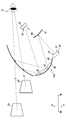
- a HUD device 100 according to the first embodiment of the present disclosure shown in FIG. 1 is mounted on a vehicle A, and provides various information related to the vehicle A to a driver D of the vehicle A.
- the HUD device 100 is disposed in front of the driver's seat where the driver D is seated, and is accommodated in the instrument panel of the vehicle A.
- the HUD device 100 projects a plurality of (two) display image lights onto the projection area PA of the windshield WS.
- the light projected onto the windshield WS is reflected toward the driver D side by the projection area PA, and reaches an eye box defined in advance so as to be positioned around the head of the driver D.
- the driver D whose eye point is positioned in the eye box, can visually recognize the light of the display image as a virtual image superimposed on the foreground.
- the driver D can recognize various kinds of information by perceiving a virtual image.
- the various information displayed in the virtual image includes vehicle state information such as the vehicle speed and the remaining amount of fuel, and navigation information such as route guidance.
- the windshield WS is formed in a curved plate shape using a light-transmitting material such as glass.
- the windshield WS is disposed in a posture inclined with respect to the horizontal direction and the vertical direction of the vehicle A.
- the windshield WS functions as one of optical systems for forming a virtual image.
- the projection area PA defined on the surface of the windshield WS on the vehicle interior side is curved in a concave shape with a curvature that continuously changes in both the horizontal and vertical directions in relation to the design of the vehicle A. Yes.
- the projection area PA may be formed by a structure attached to the windshield WS, for example, a vapor deposition film or a film for increasing the reflectance of light.
- the plurality of virtual images displayed by the HUD device 100 include a near virtual image 29 and a far virtual image 39.
- the range in which the far imaginary image 39 can be displayed and the range in which the near imaginary image 29 can be displayed have a horizontally long rectangular shape.
- the size that can be displayed as the far virtual image 39 is larger than the size that can be displayed as the near virtual image 29.
- the near virtual image 29 and the far virtual image 39 are formed at different positions in the front-rear direction of the vehicle A.
- the near virtual image 29 is formed in a position closer to the windshield WS than the far virtual image 39, specifically, in a space of about 2 to 3 meters in front of the vehicle A from the eye point.
- the far imaginary image 39 is formed at a position farther from the windshield WS than the near imaginary image 29, specifically, in a space of about 10 to 20 meters in front of the vehicle A from the eye point.
- the near virtual image 29 is displayed about 2 m ahead of the eye point
- the far virtual image 39 is displayed about 15 m ahead of the eye point.
- the image formation positions of the near virtual image 29 and the far virtual image 39 are also shifted in the vertical (vertical) direction when viewed from the driver D.
- the imaging position of the near virtual image 29 is set to be slightly below the eye point, that is, below the far virtual image 39.
- a vehicle speed, an indicator, an icon, and the like are displayed as the near virtual image 29.
- the imaging position of the far imaginary image 39 is set to be approximately the same height as the eye point.
- the distant image 39 functions as an augmented reality (AR) display by being superimposed on the road surface or the like on the appearance of the driver D.
- AR augmented reality
- the lower edge portion of the far-imagined image 39 may be positioned below the upper edge portion of the near-virtual image 29 when viewed from the driver D.
- the range in which the far virtual image 39 can be displayed may be a rectangular shape that is partially cut away so as to avoid the range in which the near virtual image 29 can be displayed.
- the lower edge portion of the far-imaging image 39 and the upper edge portion of the near-virtual image 29 may be separated in the vertical direction.
- the HUD device 100 includes a first display 20, a second display 30, a control circuit 90, a magnifying optical element 40, a correction optical element 60, and the like.
- the first display 20 has a display configuration in which the light of the near display image 28 formed as the near virtual image 29 is emitted toward the magnifying optical element 40.
- the first display 20 has a first display surface 21 that displays the near display image 28 by light emission.
- the first indicator 20 is fixed to the housing or the like of the HUD device 100 with the first display surface 21 facing the magnifying optical element 40.
- the first display 20 is disposed behind the magnifying optical element 40 and above the second display 30.
- the first indicator 20 is arranged closer to the magnifying optical element 40 than to the correction optical element 60.
- the first display 20 includes a liquid crystal display panel 22 and a backlight 23.
- the liquid crystal display panel 22 forms a first display surface 21.
- the first display surface 21 is a flat surface with substantially no curvature, and is a horizontally long rectangular shape. A large number of pixels are two-dimensionally arranged on the first display surface 21. Each pixel is provided with red, green, and blue sub-pixels.
- the liquid crystal display panel 22 displays various near-display images 28 in color on the first display surface 21 by controlling the light transmittance of the sub-pixels.
- the backlight 23 has a plurality of LEDs that emit white light source light, and a prism that guides the light emitted from each LED to the liquid crystal display panel 22.
- the light radiated from each LED is guided to the back side of the first display surface 21 to transmit and illuminate the near display image 28 drawn on the first display surface 21.
- the light of the near display image 28 transmitted through the first display surface 21 is projected onto the magnifying optical element 40.
- the second display 30 has a display configuration in which the light of the far display image 38 formed as the far virtual image 39 is emitted toward the correction optical element 60.
- the second display 30 has a second display surface 31 for emitting and displaying the far display image 38.
- the second display 30 is fixed to the housing or the like of the HUD device 100 with the second display surface 31 facing the correction optical element 60.
- the second indicator 30 is located between the magnifying optical element 40 and the correction optical element 60 in the front-rear direction of the vehicle A.
- the second indicator 30 is disposed below the magnifying optical element 40 and the correction optical element 60.
- the second display 30 includes a liquid crystal display panel 32, a backlight 33, and the like.
- the liquid crystal display panel 32 forms a second display surface 31. Similar to the first display surface 21, the second display surface 31 is a flat surface having substantially no curvature and is a horizontally long rectangular shape. The area of the second display surface 31 is wider than the area of the first display surface 21. On the second display surface 31, a large number of pixels are arranged two-dimensionally.
- the liquid crystal display panel 32 displays various distant display images 38 in color on the second display surface 31 by individually controlling the light transmittance of the plurality of sub-pixels constituting each pixel.
- the backlight 33 has substantially the same configuration as the backlight 23.
- the light emitted from each LED of the backlight 33 is guided to the back side of the second display surface 31 to transmit and illuminate the far display image 38 drawn on the second display surface 31.
- the light of the far display image 38 transmitted through the second display surface 31 is reflected by the correction optical element 60 and projected onto the magnifying optical element 40.
- the control circuit 90 is a circuit that controls the display of the near virtual image 29 and the far virtual image 39 by the HUD device 100.
- the control circuit 90 is mainly configured by a microcontroller having a processor, a RAM, a storage medium, and the like.
- the control circuit 90 is electrically connected to the display control device 98 mounted on the vehicle A, the first display device 20, the second display device 30, and the like.
- the display control device 98 acquires the information of the vehicle A through the communication bus 99 mounted on the vehicle, and determines the display mode of the near virtual image 29 and the far virtual image 39 corresponding to the situation.
- the control circuit 90 controls the first display device 20 and the second display device 30 based on a command signal from the display control device 98, thereby passing information necessary for the driver D through the near virtual image 29 and the far virtual image 39. Provide to driver D.
- the magnifying optical element 40 is a reflecting mirror in which a metal such as aluminum is vapor-deposited on the surface of a colorless and transparent substrate made of synthetic resin or glass.
- the magnifying optical element 40 is formed in a horizontally-long rectangular plate shape as a whole.
- the magnifying optical element 40 is curved so that the aluminum deposition surface is concave.
- the magnifying optical element 40 is disposed below the projection area PA and in front of the correction optical element 60.
- the magnifying optical element 40 is provided with an magnifying reflection surface 41.
- the magnifying optical element 40 is held by the housing or the like of the HUD device 100 in a posture in which the magnifying reflection surface 41 faces the first display device 20 and the correction optical element 60.
- the enlarged reflecting surface 41 is a horizontally long rectangular shape that is curved in a wave shape in the thickness direction of the magnifying optical element 40.
- the enlarged reflection surface 41 is formed as a concave free-form surface having different curvatures in the longitudinal direction and the lateral direction.
- the curvature defined in each direction of the enlarged reflecting surface 41 may not be constant and may be different at each location of the enlarged reflecting surface 41.
- the enlarged reflection surface 41 is disposed so as to straddle both the light path of the near display image 28 and the light path of the far display image 38. Both the light of the near display image 28 emitted from the first display surface 21 and the light of the far display image 38 reflected by the correction optical element 60 are incident on the enlarged reflection surface 41.
- the first incident area 42 is located above the second incident area 43.
- the second incident area 43 is wider than the first incident area 42.
- the magnifying optical element 40 spreads the light of the far display image 38 and the far imaginary image 39 by the magnifying reflection surface 41 curved in a concave shape, and reflects the light upward toward the windshield WS side. Due to the reflection on the enlarged reflection surface 41, a near virtual image 29 and a far virtual image 39 enlarged from the near display image 28 and the far display image 38 are formed.
- the enlargement ratio of the far imaginary image 39 relative to the far display image 38 is larger than the enlargement ratio of the near imaginary image 29 relative to the near display image 28.
- the correction optical element 60 is a reflecting mirror in which a metal such as aluminum is vapor-deposited on the surface of a colorless and transparent base material made of synthetic resin or glass, like the magnifying optical element 40.
- the correction optical element 60 is formed in a rectangular plate shape smaller than the correction optical element 60 as a whole.
- the correction optical element 60 is curved such that the aluminum vapor deposition surface is convex.
- the correction optical element 60 is located in the optical path of the light of the far display image 38.
- the correction optical element 60 is held in the housing of the HUD device 100 behind the magnifying optical element 40 and the second display 30.
- the correction optical element 60 is disposed slightly below the first display device 20 in the vertical direction, and is disposed at a position farther from the enlarged reflection surface 41 than the first display device 20.
- a correction reflecting surface 61 is formed on the correction optical element 60.
- the correction optical element 60 is held on the housing or the like of the HUD device 100 with the correction reflection surface 61 facing the second display surface 31 and the enlarged reflection surface 41.
- the correction optical element 60 is disposed between the first display surface 21 and the magnifying optical element 40 in the optical path of the far display image 38 from the first display surface 21 to the projection area PA.
- the optical path of the light of the far display image 38 from the correction reflecting surface 61 toward the second incident region 43 is defined so as not to overlap the first display 20.
- the correction reflecting surface 61 is formed as a concave free-form surface having different curvatures in the longitudinal direction and the lateral direction.
- the curvature defined in each direction of the correction reflection surface 61 may not be constant, and may be different at each location of the correction reflection surface 61.
- the light of the far display image 38 emitted from the second display surface 31 is incident on the correction reflection surface 61.
- the correction reflection surface 61 reflects the light of the far display image 38 emitted from the second display surface 31 toward the front on the magnifying optical element 40 side.
- the correction optical element 60 makes the optical path distance from the second display surface 31 to the enlarged reflecting surface 41 larger than the optical path distance from the first display surface 21 to the enlarged reflecting surface 41. It is long.
- the windshield WS is used as an optical system for forming the virtual images 29 and 39.
- the windshield WS is not curved with an optically preferable curvature. Therefore, the near-virtual image 29 and the far-virtual image 39 are optically affected by the reflection at the projection area PA. Therefore, the optical elements provided in the HUD device 100, that is, the magnifying optical element 40 and the correction optical element 60 are designed so as to correct the optical influence caused by the reflection at the windshield WS.
- the optical influence is, for example, field curvature and astigmatism.
- the field curvature is a phenomenon in which a display image displayed in a planar shape is curved in the front-rear direction along the optical axis due to the concave shape of the projection area PA.
- Astigmatism is a phenomenon in which individual point images constituting a virtual image are deformed due to a mismatch in focal length at each position of the projection area PA.
- the magnifications of the near virtual image 29 and the far virtual image 39 are different from each other. Therefore, the optical influence on the far-virtual image 39 due to reflection at the projection area PA is larger than the optical influence on the near-virtual image 29 due to reflection at the projection area PA as the magnification is increased. Become.
- one magnifying optical element 40 plays an optical role of reflecting each light of the near display image 28 and the far display image 38, and the display of the near virtual image 29 and the far virtual image 39. Shared with view. Therefore, it is very difficult to make the curved shape of the enlarged reflecting surface 41 suitable for correcting both the near display image 28 and the far display image 38.
- the enlarged reflection surface 41 is set to a curved shape suitable for correcting optical influences generated in the near display image 28.
- the imaging performance of the near-virtual image 29 depends on the magnified reflecting surface 41 because it is hardly affected by the shape of the windshield WS. Even correction alone can be adequately secured.
- the correction reflecting surface 61 is set to a curved shape suitable for correcting a part of the optical influence generated in the far display image 38 that cannot be corrected by the enlarged reflecting surface 41.
- the correction optical element 60 corrects the curvature of field, astigmatism, and the like generated in the far virtual image 39 together with the magnifying optical element 40. As a result, the light of the far display image 38 passes through the correction optical element 60 and the magnifying optical element 40 and is clearly formed as a far virtual image 39 even if it is reflected by the projection area PA.
- the optical influence that is assumed to occur in the far virtual image 39 due to reflection by the windshield WS can be corrected not only by the magnifying optical element 40 but also by the correction optical element 60. Therefore, even if the magnifying optical element 40 is configured to reflect each light of the near display image 28 and the far display image 38, the light of the far display image 38 is different from the light of the near display image 28. Then, a far virtual image 39 is formed at a position farther than the near virtual image 29.
- the correction optical element 60 is optimized so that the imaging performance of the far virtual image 39 is ensured. can do. Therefore, the HUD device 100 can ensure the imaging performance of the near virtual image 29 and the far virtual image 39 even when the plurality of display images 28 and 38 share the magnifying optical element 40.
- the HUD device 100 can be prevented from being enlarged and mountability to the vehicle A can be ensured. Further, according to the use of the correction optical element 60, the imaging performance of one of the near virtual image 29 and the far virtual image 39 having greatly different magnifications may be sacrificed, or both imaging performances may be degraded evenly. Is no longer necessary.
- the correction optical element 60 of the first embodiment is located between the second display surface 31 and the enlarged reflection surface 41. Therefore, the correction optical element 60 can correct the light of the far display image 38 at a stage before being magnified by the magnified reflection surface 41. If it is the above structure, since the size of the correction
- the first incident area 42 and the second incident area 43 are defined to overlap.
- the magnifying optical element 40 can be miniaturized.
- the configuration in which the optical effect generated in the far virtual image 39 is corrected by the addition of the correction optical element 60 is a configuration in which the first incident region 42 and the second incident region 43 overlap and are defined. , 39 is particularly suitable for ensuring the imaging performance.
- the correction optical element 60 is constituted by a reflecting mirror, the optical path of the light of the far display image 38 can be folded inside the HUD device 100. As a result, the dimension of the HUD device 100 in the front-rear direction can be reduced. According to the above, the HUD device 100 excellent in mountability that can be mounted on the vehicle A in which the accommodation space is difficult to expand in the front-rear direction is realized.
- the corrected reflecting surface 61 corresponds to a “reflecting surface”
- the vehicle A corresponds to a “moving body”
- the driver D corresponds to an “occupant”.
- the second embodiment of the present disclosure shown in FIG. 3 is a modification of the first embodiment.
- the arrangement of the first indicator 20 and the second indicator 30 is different from that of the first embodiment.
- an optical lens 261 is provided as the correction optical element 260.
- the first indicator 20 is fixed to a housing or the like in a posture in which the first display surface 21 faces the first incident area 42.
- the first indicator 20 is disposed above the optical lens 261.
- the distance from the enlarged reflection surface 41 to the first display surface 21 is set longer than the distance from the enlarged reflection surface 41 to the optical lens 261.
- the second display 30 is disposed on the opposite side of the enlarged reflection surface 41 with the optical lens 261 interposed therebetween.
- the second indicator 30 is fixed to the housing or the like in a posture in which the second display surface 31 faces the second incident region 43.
- the distance from the enlarged reflection surface 41 to the second display surface 31 is set longer than the distance from the enlarged reflection surface 41 to the first display surface 21.
- the light path of the far display image 38 is set below the light path of the near display image 28.
- the light path of the far display image 38 is defined along the light path of the near display image 28.
- the optical lens 261 is formed of a material having high translucency such as glass.
- the optical lens 261 is, for example, a biconvex lens, a plano-convex lens, or a convex cylindrical lens.
- the pair of refractive surfaces 262 and 263 formed on the optical lens 261 may be a convex cylindrical surface, a spherical surface, an aspherical surface, or a free-form surface.
- one of the two refracting surfaces 262 and 263 may be planar.
- the optical lens 261 is disposed between the second display surface 31 and the second incident region 43.
- the optical lens 261 is fixed to the housing or the like at a position closer to the second display surface 31 than the second incident area 43.
- the optical lens 261 is provided at a position that does not overlap the optical path of the light of the near display image 28 that travels from the first display surface 21 toward the first incident region 42.
- the refractive surface 262 faces the second display surface 31.
- the refractive surface 263 faces the second incident region 43.
- the light of the far display image 38 incident on the optical lens 261 from the second display 30 passes through the optical lens 261 and reaches the second incident region 43.
- the optical lens 261 emits the light of the far display image 38 toward the magnifying optical element 40 side while refracting the light of the far display image 38 by the respective refractive surfaces 262 and 263.
- Each refracting surface 262, 263 is an optical device that corrects optical effects occurring in the far display image 38 in cooperation with the enlarged reflecting surface 41, like the correcting reflecting surface 61 (see FIG. 1) of the first embodiment. It has a special function. Specifically, each refracting surface 262, 263 corrects the portion of the optical effect that occurs in the far display image 38 due to reflection at the projection area PA of the windshield WS that the enlarged reflecting surface 41 cannot correct. It is an optimal shape.
- the optical lens 261 used as the correction optical element 260 has the same effect as the first embodiment, and the imaging performance of both the near virtual image 29 and the far virtual image 39 can be secured. Become.
- the second embodiment it is possible to arrange the second display 30 side by side with the first display 20 by employing the transmission type correction optical element 260.
- the third embodiment of the present disclosure shown in FIG. 4 is a modification of the second embodiment.
- the HUD device 300 of the third embodiment is provided with a near correction optical element 160 in addition to the far correction optical element 260 that is substantially the same as the correction optical element of the second embodiment.
- the near correction optical element 160 has an optical lens 161. Similar to the optical lens 261, the optical lens 161 is a biconvex lens, a plano-convex lens, a convex cylindrical lens, or the like formed of a material having high translucency such as glass.
- the optical lens 161 is disposed between the first display surface 21 and the first incident region 42.
- the optical lens 161 is fixed to the housing or the like at a position closer to the first display surface 21 than the first incident region 42.
- the optical lens 161 is arranged side by side with the optical lens 261, and is provided at a position that does not overlap with the optical path of the light of the far display image 38 from the second display surface 31 toward the second incident region 43.
- the optical lens 161 has a refractive surface 162 that faces the first display surface 21 and a refractive surface 163 that faces the first incident region 42.
- the light of the near display image 28 incident on the optical lens 161 from the first display device 20 passes through the optical lens 161 and reaches the first incident region 42.
- the optical lens 161 emits the light of the near display image 28 toward the magnifying optical element 40 side while refracting the light of the near display image 28 by the respective refractive surfaces 162 and 163.
- Each of the refractive surfaces 162 and 163 has an optical function of correcting an optical influence generated in the near display image 28 in cooperation with the enlarged reflection surface 41. Specifically, each of the refractive surfaces 162 and 163 is optimal for correcting an amount that cannot be corrected by the magnifying reflecting surface 41 among optical effects generated in the near display image 28 due to reflection by the windshield WS. It is a free-form surface.
- the same effects as those of the second embodiment can be obtained, and the imaging performance of the near virtual image 29 and the far virtual image 39 can be secured.
- the optical effect assumed to occur in the near virtual image 29 can be corrected more precisely by the optical action of the near correction optical element 160. Therefore, by adjusting the shapes of the near correction optical element 160 and the far correction optical element 260, it is possible to further improve the imaging performance of the near virtual image 29 and the far virtual image 39.
- FIG. 5 4th embodiment of this indication shown in FIG. 5 is another modification of 1st embodiment.
- the position of the 1st indicator 20 differs from 1st embodiment.
- the first indicator 20 and the correction optical element 60 are disposed at substantially the same distance from the enlarged reflection surface 41.
- the first display surface 21 and the correction reflection surface 61 are arranged in a vertical direction so that both face the enlarged reflection surface 41.
- the distance from the first incident area 42 to the first display surface 21 is substantially the same as the distance from the second incident area 43 to the correction reflecting surface 61.
- the correction optical element 60 is located on the opposite side of the windshield WS across the first display surface 21 with the HUD device 400 mounted on the vehicle A.
- the correction optical element 60 is disposed below the first display device 20.
- the fifth embodiment of the present disclosure illustrated in FIG. 6 is still another modification of the fourth embodiment.
- the first indicator 20 is farther from the magnifying optical element 40 than in the fourth embodiment, and the correction reflecting surface 61 is formed among both surfaces of the correction optical element 60. Not arranged on the back side. Therefore, the distance from the first incident area 42 to the first display surface 21 is longer than the distance from the second incident area 43 to the correction reflecting surface 61.
- the correction optical element 60 is provided at a position that does not overlap the optical path of the light of the near display image 28 that travels from the first display surface 21 toward the first incident region 42.
- the correction optical element 60 is located closer to the first display surface 21 than the second incident region 43.
- the second display surface 31 of the second display 30 is located on the opposite side of the first display surface 21 with the correction optical element 60 interposed therebetween.
- a display device that is a combination of a liquid crystal display panel and a backlight is employed as a configuration that displays each display image by light emission.
- the configuration of the display may be changed as appropriate.
- a display using organic EL Electrode
- the first display surface and the second display surface may be provided in one display device.
- At least one of the first display surface and the second display surface may be a projection surface (screen) on which an image is projected by the projection device.
- a projection surface screen
- an LCD Liquid Crystal Display
- laser projector a laser projector
- DLP Digital Light Processing: registered trademark
- the HUD device is a bifocal HUD that forms virtual images on two different focal points.
- the HUD device may be a multi-focus HUD that forms virtual images at three or more focal points by projecting light of three or more display images onto a projection region.
- the imaging position can be changed as appropriate. For example, a distant image may be formed at a position of about 5 to 7 m from the eye point.
- each display image is displayed in color.
- the display image and the virtual image may be a design that emits and displays a single color.
- the sizes of the display image and the virtual image may be changed as appropriate.
- the range in which each virtual image can be displayed may be vertically long.
- the imaging positions and orientations of the far and near virtual images may be changed as appropriate.
- the configuration of the optical system used in the HUD device may be changed as appropriate.
- the correction optical element may have any of a reflective configuration, a transmissive configuration, and a configuration having both reflection and transmission.
- the correction optical element (far correction optical element), the near correction optical element, and the magnifying optical element may not be one each.
- the number of reflecting mirrors and the number of lenses provided in the HUD device may be changed as appropriate.
- a plurality of far correction optical elements or a plurality of near correction optical elements may be arranged on each optical path.
- another magnifying optical element may be further provided in addition to the magnifying optical element 40 (see FIG. 1 and the like) shared for displaying the near-virtual image and the far-virtual image.
- the correction optical element may have a function of increasing the magnification of the far-imaging image by an optical action that spreads the light of the far-display image, like the magnification optical element.
- correction optical element far correction optical element
- the correction optical element may be disposed between the magnifying optical element and the projection region in the optical path of the light of the far display image.
- the near correction optical element may be disposed between the magnifying optical element and the projection region in the optical path of the light of the near display image.
- Each shape of the reflecting surface and the refracting surface in the correcting optical element may be changed as appropriate so that an effective correcting action is exhibited.
- the reflecting surface and the refracting surface are preferably free-form surfaces in order to maximize the correction action, but if sufficient correction action can be exerted, from the viewpoint of reducing manufacturing costs, the toroidal shape and the cylindrical shape can be used. There may be.
- the optical lens of the second embodiment was provided at a position closer to the second display surface than the enlarged reflection surface.
- the optical lens may be provided at a position closer to the enlarged reflection surface than the second display surface.
- regulated on an expansion reflective surface may be mutually separated.
- the optical paths of the light of the near display image and the far display image incident on the enlarged reflecting surface are defined substantially in parallel.
- the layout of each optical path inside the HUD device may be changed as appropriate. For example, a layout in which two optical paths intersect each other may be employed.
- the moving body on which the HUD device is mounted may be a ship other than a vehicle, an aircraft, a transportation device, or the like.
- the passenger of the moving body may not be a driver who controls the moving body.
Abstract
A head-up display device projects a near display image (28) and a far display image (38) onto a windshield (WS) and visibly displays a near virtual image (29) and a far virtual image (39) that are imaged at positions different from each other. The head-up display device is provided with, in addition to a first display surface (21) that emits and displays the near display image and a second display surface (31) that emits and displays the far display image, a magnification optical element (40) and a correction optical element (60). The magnification optical element reflects light emitted from the first display surface and the second display surface toward the windshield while magnifying said light. The correction optical element is provided in the optical path of light of the far display image, and, together with the magnification optical element, corrects an optical effect predicted to occur in the far virtual image due to reflection by the windshield.
Description
本出願は、2017年2月3日に出願された日本特許出願2017-18664号に基づくもので、ここにその記載内容を援用する。
This application is based on Japanese Patent Application No. 2017-18664 filed on Feb. 3, 2017, the contents of which are incorporated herein by reference.
この明細書による開示は、移動体の乗員によって視認可能な虚像を表示するヘッドアップディスプレイ装置に関する。
The disclosure according to this specification relates to a head-up display device that displays a virtual image that can be visually recognized by an occupant of a moving object.
従来、車両等のウィンドシールドに表示像を投影し、投影された表示像の虚像を、運転者等によって視認可能に表示するヘッドアップディスプレイ装置(以下、「HUD装置」)が知られている。例えば特許文献1には、こうしたHUD装置の一種として、二つの表示像をウィンドシールドに投影し、各表示像の虚像を互いに異なる位置に結像させる構成が開示されている。
Conventionally, a head-up display device (hereinafter referred to as “HUD device”) that projects a display image on a windshield of a vehicle or the like and displays a virtual image of the projected display image so as to be visible by a driver or the like is known. For example, Patent Document 1 discloses a type of HUD device in which two display images are projected onto a windshield and virtual images of the display images are formed at different positions.
特許文献1のHUD装置には、二つのスクリーンと、各スクリーンに第一表示画像及び第二表示画像を表示させる投影装置と、各スクリーンから射出される各表示画像の光をウィンドシールドへ向けて反射させる凹面鏡と、が設けられている。投影装置は、プロジェクタから射出された光を、結像位置調整ミラーにより二つのスクリーンへ向けて反射させる。結像位置調整ミラーには、当該ミラーから各スクリーンまでの結像距離の差を調整する構成として、自由曲面状の第二反射面が形成されている。
In the HUD device of Patent Document 1, two screens, a projection device that displays a first display image and a second display image on each screen, and light of each display image emitted from each screen are directed toward the windshield. And a concave mirror for reflection. The projection device reflects light emitted from the projector toward the two screens by the imaging position adjusting mirror. The imaging position adjustment mirror is provided with a second curved surface having a free-form surface as a configuration for adjusting the difference in imaging distance from the mirror to each screen.
さて、一般的に車両等の移動体のウィンドシールドは、湾曲形状に形成されている。故に、ウィンドシールドにて表示画像を反射させる構成では、例えば像面湾曲や非点収差といった光学的な影響が虚像に生じる。そして、特許文献1のHUD装置のように、異なる位置に第一虚像及び第二虚像を結像させる構成では、ウィンドシールドでの反射によって各虚像に生じる光学的な影響の大きさは、互いに異なってしまう。
Now, generally, the windshield of a moving body such as a vehicle is formed in a curved shape. Therefore, in the configuration in which the display image is reflected by the windshield, optical effects such as field curvature and astigmatism occur in the virtual image. And in the structure which forms a 1st virtual image and a 2nd virtual image in a different position like the HUD apparatus of patent document 1, the magnitude | size of the optical influence which arises in each virtual image by reflection by a windshield differs mutually. End up.
しかし、特許文献1のHUD装置では、例えば大型化を抑制するために、第一表示画像及び第二表示画像で凹面鏡が共用されている。故に、ウィンドシールドでの反射によって各虚像に発生する光学的な影響は、実質的に凹面鏡だけで補正しなくてはならない。そのため、第一表示画像の光は、第二表示画像の光と同様の光学的な補正しか受けることができないまま、第二虚像よりも遠い位置に第一虚像として結像される。以上により、凹面鏡の形状を工夫して第二虚像の結像性能を担保できたとしても、第一虚像の結像性能は、担保困難であった。
However, in the HUD device of Patent Document 1, a concave mirror is shared between the first display image and the second display image, for example, in order to suppress an increase in size. Therefore, the optical influence generated in each virtual image due to the reflection at the windshield must be substantially corrected only by the concave mirror. Therefore, the light of the first display image is imaged as the first virtual image at a position farther than the second virtual image while receiving only the same optical correction as the light of the second display image. As described above, even if the shape of the concave mirror is devised to ensure the imaging performance of the second virtual image, it is difficult to ensure the imaging performance of the first virtual image.
本開示の目的は、凹面鏡のような拡大光学素子を共用していても、二つの虚像の結像性能が担保可能なHUD装置を提供することにある。
An object of the present disclosure is to provide a HUD device that can guarantee the imaging performance of two virtual images even if a magnifying optical element such as a concave mirror is shared.
本開示の一態様において、HUD装置は、移動体のウィンドシールドに二つの表示像を投影し、互いに異なる位置に結像される二つの表示像の虚像を、移動体の乗員によって視認可能に表示するHUD装置であって、二つの表示像のうちでウィンドシールドに近い位置に近虚像として結像される近表示像、を発光表示する第一表示面と、二つの表示像のうちで近虚像よりもウィンドシールドから遠い位置に遠虚像として結像される遠表示像、を発光表示する第二表示面と、近表示像及び遠表示像からそれぞれ拡大された近虚像及び遠虚像が結像されるよう、第一表示面及び第二表示面から射出される光を広げつつウィンドシールド側へ向けて反射させる拡大光学素子と、遠表示像の光の光路に設けられ、ウィンドシールドでの反射によって遠虚像に発生が想定される光学的な影響を、拡大光学素子と共に補正する補正光学素子と、を備える。
In one aspect of the present disclosure, the HUD device projects two display images onto a windshield of a moving body, and displays a virtual image of the two display images formed at different positions so as to be visually recognized by a passenger of the moving body. A first display screen for emitting and displaying a near display image formed as a near virtual image at a position close to the windshield among the two display images, and a near virtual image of the two display images. A second display surface that emits and displays a far display image formed as a far imaginary image at a position farther from the windshield, and a near imaginary image and a far imaginary image enlarged from the near display image and the far display image are formed, respectively. In this way, the light emitted from the first display surface and the second display surface is expanded and reflected toward the windshield side, and is provided in the optical path of the light of the far display image. The optical effect of generating the virtual image is assumed, and a correcting optical element for correcting with magnifying optics.
この態様によれば、ウィンドシールドでの反射によって遠虚像に発生が想定される光学的な影響は、拡大光学素子だけでなく、補正光学素子によっても、補正され得る。故に、拡大光学素子が近表示像及び遠表示像の各光を共にウィンドシールド側へ向けて反射させる構成であっても、遠表示像の光は、近表示像の光とは異なる光学的な補正をなされたうえで、近虚像よりも遠い位置に遠虚像として結像される。
According to this aspect, the optical influence that is assumed to occur in the distant image due to reflection by the windshield can be corrected not only by the magnifying optical element but also by the correcting optical element. Therefore, even if the magnifying optical element is configured to reflect each light of the near display image and the far display image toward the windshield side, the light of the far display image is different from the light of the near display image. After correction, an image is formed as a far virtual image at a position farther from the near virtual image.
以上によれば、近虚像の結像性能が担保されるように拡大光学素子を最適化したうえで、遠虚像の結像性能が担保されるように、補正光学素子を最適化することができる。したがって、ヘッドアップディスプレイ装置は、二つの表示像で拡大光学素子を共用していても、二つの虚像の結像性能を担保可能となる。
According to the above, it is possible to optimize the correction optical element so that the imaging performance of the far-virtual image is secured after the magnifying optical element is optimized so that the imaging performance of the near-virtual image is secured. . Therefore, the head-up display device can secure the imaging performance of two virtual images even if the magnifying optical element is shared by the two display images.
以下、本開示の複数の実施形態を図面に基づいて説明する。尚、各実施形態において対応する構成要素には同一の符号を付すことにより、重複する説明を省略する場合がある。各実施形態において構成の一部分のみを説明している場合、当該構成の他の部分については、先行して説明した他の実施形態の構成を適用することができる。また、各実施形態の説明において明示している構成の組み合わせばかりではなく、特に組み合わせに支障が生じなければ、明示していなくても複数の実施形態の構成同士を部分的に組み合わせることができる。そして、複数の実施形態及び変形例に記述された構成同士の明示されていない組み合わせも、以下の説明によって開示されているものとする。
Hereinafter, a plurality of embodiments of the present disclosure will be described with reference to the drawings. In addition, the overlapping description may be abbreviate | omitted by attaching | subjecting the same code | symbol to the corresponding component in each embodiment. When only a part of the configuration is described in each embodiment, the configuration of the other embodiment described above can be applied to the other part of the configuration. Moreover, not only the combination of the configurations explicitly described in the description of each embodiment, but also the configuration of a plurality of embodiments can be partially combined even if they are not explicitly described, as long as there is no problem in the combination. And the combination where the structure described in several embodiment and the modification is not specified shall also be disclosed by the following description.
(第一実施形態)
図1に示す本開示の第一実施形態によるHUD装置100は、車両Aに搭載され、車両Aに関連する各種の情報を車両Aの運転者Dに提供する。HUD装置100は、運転者Dの着座する運転席の前方に配置されており、車両Aのインスツルメントパネルに収容されている。 (First embodiment)
AHUD device 100 according to the first embodiment of the present disclosure shown in FIG. 1 is mounted on a vehicle A, and provides various information related to the vehicle A to a driver D of the vehicle A. The HUD device 100 is disposed in front of the driver's seat where the driver D is seated, and is accommodated in the instrument panel of the vehicle A.
図1に示す本開示の第一実施形態によるHUD装置100は、車両Aに搭載され、車両Aに関連する各種の情報を車両Aの運転者Dに提供する。HUD装置100は、運転者Dの着座する運転席の前方に配置されており、車両Aのインスツルメントパネルに収容されている。 (First embodiment)
A
HUD装置100は、複数(二つ)の表示像の光をウィンドシールドWSの投影領域PAに投影する。ウィンドシールドWSに投影された光は、投影領域PAによって運転者D側へ向けて反射され、運転者Dの頭部周辺に位置するよう予め規定されたアイボックスに到達する。アイボックスにアイポイントを位置させた運転者Dは、表示像の光を、前景に重畳された虚像として視認可能となる。運転者Dは、虚像を知覚することで、各種の情報を認識できる。虚像表示される各種情報には、車速及び燃料残量等の車両の状態情報、並びに経路案内等のナビゲーション情報が含まれている。
The HUD device 100 projects a plurality of (two) display image lights onto the projection area PA of the windshield WS. The light projected onto the windshield WS is reflected toward the driver D side by the projection area PA, and reaches an eye box defined in advance so as to be positioned around the head of the driver D. The driver D, whose eye point is positioned in the eye box, can visually recognize the light of the display image as a virtual image superimposed on the foreground. The driver D can recognize various kinds of information by perceiving a virtual image. The various information displayed in the virtual image includes vehicle state information such as the vehicle speed and the remaining amount of fuel, and navigation information such as route guidance.
ウィンドシールドWSは、ガラス等の透光性を有する材料により、湾曲した板状に形成されている。ウィンドシールドWSは、車両Aの水平方向及び鉛直方向に対して傾斜した姿勢で配置されている。ウィンドシールドWSは、虚像を結像させるための光学系の一つとして機能する。ウィンドシールドWSの車室内側の面に規定された投影領域PAは、車両Aのデザインに関連して、横方向及び縦方向のいずれにも連続的に変化する曲率で、凹面状に湾曲している。尚、投影領域PAは、ウィンドシールドWSに貼り付けられた構成、例えば光の反射率を高めるための蒸着膜又はフィルム等によって形成されていてもよい。
The windshield WS is formed in a curved plate shape using a light-transmitting material such as glass. The windshield WS is disposed in a posture inclined with respect to the horizontal direction and the vertical direction of the vehicle A. The windshield WS functions as one of optical systems for forming a virtual image. The projection area PA defined on the surface of the windshield WS on the vehicle interior side is curved in a concave shape with a curvature that continuously changes in both the horizontal and vertical directions in relation to the design of the vehicle A. Yes. Note that the projection area PA may be formed by a structure attached to the windshield WS, for example, a vapor deposition film or a film for increasing the reflectance of light.
HUD装置100によって表示される複数の虚像には、近虚像29及び遠虚像39が含まれている。遠虚像39を表示可能な範囲及び近虚像29を表示可能な範囲は、それぞれ横長の矩形状となっている。遠虚像39として表示可能なサイズは、近虚像29として表示可能なサイズよりも大きくされている。
The plurality of virtual images displayed by the HUD device 100 include a near virtual image 29 and a far virtual image 39. The range in which the far imaginary image 39 can be displayed and the range in which the near imaginary image 29 can be displayed have a horizontally long rectangular shape. The size that can be displayed as the far virtual image 39 is larger than the size that can be displayed as the near virtual image 29.
加えて近虚像29及び遠虚像39は、車両Aの前後方向において、互いに異なる位置に結像される。近虚像29は、遠虚像39よりもウィンドシールドWSに近い位置、具体的には、アイポイントから車両Aの前方に2~3メートル程度の空間中に結像される。遠虚像39は、近虚像29よりもウィンドシールドWSから遠い位置、具体的には、アイポイントから車両Aの前方に10~20メートル程度の空間中に結像される。一例としては、近虚像29は、アイポイントよりも2m程度前方に表示され、遠虚像39は、アイポイントよりも15m程度前方に表示される。
In addition, the near virtual image 29 and the far virtual image 39 are formed at different positions in the front-rear direction of the vehicle A. The near virtual image 29 is formed in a position closer to the windshield WS than the far virtual image 39, specifically, in a space of about 2 to 3 meters in front of the vehicle A from the eye point. The far imaginary image 39 is formed at a position farther from the windshield WS than the near imaginary image 29, specifically, in a space of about 10 to 20 meters in front of the vehicle A from the eye point. As an example, the near virtual image 29 is displayed about 2 m ahead of the eye point, and the far virtual image 39 is displayed about 15 m ahead of the eye point.
さらに、近虚像29及び遠虚像39の結像位置は、運転者Dからの視認上において、鉛直(上下)方向にもずらされている。近虚像29の結像位置は、アイポイントよりも僅かに下方、即ち遠虚像39よりも下方となるように設定されている。例えば車速、インジケータ、及びアイコン等が近虚像29として表示される。遠虚像39の結像位置は、アイポイントと概ね同程度の高さとなるように設定されている。遠虚像39は、運転者Dの見かけ上で路面等に重畳されることで、拡張現実(Augmented Reality:AR)表示として機能する。例えば、右左折を指示する矢印等が遠虚像39として表示される。
Furthermore, the image formation positions of the near virtual image 29 and the far virtual image 39 are also shifted in the vertical (vertical) direction when viewed from the driver D. The imaging position of the near virtual image 29 is set to be slightly below the eye point, that is, below the far virtual image 39. For example, a vehicle speed, an indicator, an icon, and the like are displayed as the near virtual image 29. The imaging position of the far imaginary image 39 is set to be approximately the same height as the eye point. The distant image 39 functions as an augmented reality (AR) display by being superimposed on the road surface or the like on the appearance of the driver D. For example, an arrow or the like instructing a right / left turn is displayed as a far-imagined image 39.
尚、運転者Dからの視認上にて、遠虚像39の下縁部分は、近虚像29の上縁部分よりも、下方に位置していてもよい。例えば、遠虚像39を表示可能な範囲は、近虚像29を表示可能な範囲を避けるようにして、部分的に切り欠かれた矩形状であってもよい。また、運転者Dからの視認上にて、遠虚像39の下縁部分と近虚像29の上縁部分とが、上下方向に離れていてもよい。
It should be noted that the lower edge portion of the far-imagined image 39 may be positioned below the upper edge portion of the near-virtual image 29 when viewed from the driver D. For example, the range in which the far virtual image 39 can be displayed may be a rectangular shape that is partially cut away so as to avoid the range in which the near virtual image 29 can be displayed. Further, when viewed from the driver D, the lower edge portion of the far-imaging image 39 and the upper edge portion of the near-virtual image 29 may be separated in the vertical direction.
次に、HUD装置100の構成を説明する。HUD装置100は、図1及び図2に示すように、第一表示器20、第二表示器30、制御回路90、拡大光学素子40、及び補正光学素子60等によって構成されている。
Next, the configuration of the HUD device 100 will be described. As shown in FIGS. 1 and 2, the HUD device 100 includes a first display 20, a second display 30, a control circuit 90, a magnifying optical element 40, a correction optical element 60, and the like.
第一表示器20は、近虚像29として結像される近表示像28の光を、拡大光学素子40へ向けて射出する表示構成である。第一表示器20は、近表示像28を発光表示する第一表示面21を有している。第一表示器20は、第一表示面21を拡大光学素子40へ向けた姿勢にて、HUD装置100のハウジング等に固定されている。第一表示器20は、拡大光学素子40の後方、且つ、第二表示器30の上方に配置されている。第一表示器20は、補正光学素子60よりも拡大光学素子40の近くに配置されている。第一表示器20は、液晶ディスプレイパネル22及びバックライト23等によって構成されている。
The first display 20 has a display configuration in which the light of the near display image 28 formed as the near virtual image 29 is emitted toward the magnifying optical element 40. The first display 20 has a first display surface 21 that displays the near display image 28 by light emission. The first indicator 20 is fixed to the housing or the like of the HUD device 100 with the first display surface 21 facing the magnifying optical element 40. The first display 20 is disposed behind the magnifying optical element 40 and above the second display 30. The first indicator 20 is arranged closer to the magnifying optical element 40 than to the correction optical element 60. The first display 20 includes a liquid crystal display panel 22 and a backlight 23.
液晶ディスプレイパネル22は、第一表示面21を形成している。第一表示面21は、実質的に湾曲の無い平面状であって、横長の矩形状である。第一表示面21には、多数の画素が二次元状に配列されている。各画素には、赤色、緑色、及び青色のサブ画素が設けられている。液晶ディスプレイパネル22は、サブ画素の光の透過率を制御することにより、第一表示面21に種々の近表示像28をカラーにて発光表示する。
The liquid crystal display panel 22 forms a first display surface 21. The first display surface 21 is a flat surface with substantially no curvature, and is a horizontally long rectangular shape. A large number of pixels are two-dimensionally arranged on the first display surface 21. Each pixel is provided with red, green, and blue sub-pixels. The liquid crystal display panel 22 displays various near-display images 28 in color on the first display surface 21 by controlling the light transmittance of the sub-pixels.
バックライト23は、白色の光源光を放射する複数のLEDと、各LEDから放射された光を液晶ディスプレイパネル22へ導光するプリズムとを有している。各LEDから放射された光は、第一表示面21の裏面側に導光され、第一表示面21に描画された近表示像28を透過照明する。第一表示面21を透過した近表示像28の光は、拡大光学素子40に投影される。
The backlight 23 has a plurality of LEDs that emit white light source light, and a prism that guides the light emitted from each LED to the liquid crystal display panel 22. The light radiated from each LED is guided to the back side of the first display surface 21 to transmit and illuminate the near display image 28 drawn on the first display surface 21. The light of the near display image 28 transmitted through the first display surface 21 is projected onto the magnifying optical element 40.
第二表示器30は、遠虚像39として結像される遠表示像38の光を、補正光学素子60へ向けて射出する表示構成である。第二表示器30は、遠表示像38を発光表示する第二表示面31を有している。第二表示器30は、第二表示面31を補正光学素子60へ向けた姿勢にて、HUD装置100のハウジング等に固定されている。第二表示器30は、車両Aの前後方向において、拡大光学素子40及び補正光学素子60の間に位置している。第二表示器30は、拡大光学素子40及び補正光学素子60よりも下方に配置されている。第二表示器30は、第一表示器20と同様に、液晶ディスプレイパネル32及びバックライト33等によって構成されている。
The second display 30 has a display configuration in which the light of the far display image 38 formed as the far virtual image 39 is emitted toward the correction optical element 60. The second display 30 has a second display surface 31 for emitting and displaying the far display image 38. The second display 30 is fixed to the housing or the like of the HUD device 100 with the second display surface 31 facing the correction optical element 60. The second indicator 30 is located between the magnifying optical element 40 and the correction optical element 60 in the front-rear direction of the vehicle A. The second indicator 30 is disposed below the magnifying optical element 40 and the correction optical element 60. Similar to the first display 20, the second display 30 includes a liquid crystal display panel 32, a backlight 33, and the like.
液晶ディスプレイパネル32は、第二表示面31を形成している。第二表示面31は、第一表示面21と同様に、実質的に湾曲の無い平面状であって、横長の矩形状である。第二表示面31の面積は、第一表示面21の面積よりも広くされている。第二表示面31には、多数の画素が二次元状に配列されている。液晶ディスプレイパネル32は、各画素を構成する複数のサブ画素について、光の透過率を個別に制御することにより、第二表示面31に種々の遠表示像38をカラーにて発光表示する。
The liquid crystal display panel 32 forms a second display surface 31. Similar to the first display surface 21, the second display surface 31 is a flat surface having substantially no curvature and is a horizontally long rectangular shape. The area of the second display surface 31 is wider than the area of the first display surface 21. On the second display surface 31, a large number of pixels are arranged two-dimensionally. The liquid crystal display panel 32 displays various distant display images 38 in color on the second display surface 31 by individually controlling the light transmittance of the plurality of sub-pixels constituting each pixel.
バックライト33は、バックライト23と実質同一の構成である。バックライト33の各LEDから放射された光は、第二表示面31の裏面側に導光され、第二表示面31に描画された遠表示像38を透過照明する。第二表示面31を透過した遠表示像38の光は、補正光学素子60にて反射され、拡大光学素子40に投影される。
The backlight 33 has substantially the same configuration as the backlight 23. The light emitted from each LED of the backlight 33 is guided to the back side of the second display surface 31 to transmit and illuminate the far display image 38 drawn on the second display surface 31. The light of the far display image 38 transmitted through the second display surface 31 is reflected by the correction optical element 60 and projected onto the magnifying optical element 40.
制御回路90は、HUD装置100による近虚像29及び遠虚像39の表示を制御する回路である。制御回路90は、プロセッサ、RAM、及び記憶媒体等を有するマイクロコントローラを主体に構成されている。制御回路90は、車両Aに搭載された表示制御装置98、並びに第一表示器20及び第二表示器30等と電気的に接続されている。表示制御装置98は、車載された通信バス99を通じて車両Aの情報を取得し、状況に対応した近虚像29及び遠虚像39の表示態様を決定する。制御回路90は、表示制御装置98からの指令信号に基づき、第一表示器20及び第二表示器30を制御することで、運転者Dに必要な情報を、近虚像29及び遠虚像39を通じて運転者Dに提供する。
The control circuit 90 is a circuit that controls the display of the near virtual image 29 and the far virtual image 39 by the HUD device 100. The control circuit 90 is mainly configured by a microcontroller having a processor, a RAM, a storage medium, and the like. The control circuit 90 is electrically connected to the display control device 98 mounted on the vehicle A, the first display device 20, the second display device 30, and the like. The display control device 98 acquires the information of the vehicle A through the communication bus 99 mounted on the vehicle, and determines the display mode of the near virtual image 29 and the far virtual image 39 corresponding to the situation. The control circuit 90 controls the first display device 20 and the second display device 30 based on a command signal from the display control device 98, thereby passing information necessary for the driver D through the near virtual image 29 and the far virtual image 39. Provide to driver D.
拡大光学素子40は、合成樹脂又はガラス等からなる無色透明の基材の表面に、アルミニウム等の金属を蒸着させた反射鏡である。拡大光学素子40は、全体として横長の矩形の板状に形成されている。拡大光学素子40は、アルミニウムの蒸着面が凹面状となるように湾曲している。拡大光学素子40は、投影領域PAの下方、且つ、補正光学素子60の前方に配置されている。拡大光学素子40には、拡大反射面41が形成されている。拡大光学素子40は、第一表示器20及び補正光学素子60に拡大反射面41を向けた姿勢にて、HUD装置100のハウジング等に保持されている。
The magnifying optical element 40 is a reflecting mirror in which a metal such as aluminum is vapor-deposited on the surface of a colorless and transparent substrate made of synthetic resin or glass. The magnifying optical element 40 is formed in a horizontally-long rectangular plate shape as a whole. The magnifying optical element 40 is curved so that the aluminum deposition surface is concave. The magnifying optical element 40 is disposed below the projection area PA and in front of the correction optical element 60. The magnifying optical element 40 is provided with an magnifying reflection surface 41. The magnifying optical element 40 is held by the housing or the like of the HUD device 100 in a posture in which the magnifying reflection surface 41 faces the first display device 20 and the correction optical element 60.
拡大反射面41は、拡大光学素子40の板厚方向に波状に湾曲した横長の矩形状である。拡大反射面41は、長手方向及び短手方向のそれぞれに異なる曲率を有する凹状の自由曲面に形成されている。拡大反射面41の各方向に規定された曲率は、一定でなくてもよく、拡大反射面41の各箇所において異なっていてもよい。拡大反射面41は、近表示像28の光の光路及び遠表示像38の光の光路の両方に跨るよう配置されている。拡大反射面41には、第一表示面21から射出された近表示像28の光と、補正光学素子60にて反射された遠表示像38の光とが共に入射する。拡大反射面41にて、近表示像28の光が入射する第一入射領域42の少なくとも一部は、遠表示像38の光が入射する第二入射領域43の少なくとも一部と重なっている。第一入射領域42は、第二入射領域43よりも上方に位置している。第二入射領域43は、第一入射領域42よりも広い。
The enlarged reflecting surface 41 is a horizontally long rectangular shape that is curved in a wave shape in the thickness direction of the magnifying optical element 40. The enlarged reflection surface 41 is formed as a concave free-form surface having different curvatures in the longitudinal direction and the lateral direction. The curvature defined in each direction of the enlarged reflecting surface 41 may not be constant and may be different at each location of the enlarged reflecting surface 41. The enlarged reflection surface 41 is disposed so as to straddle both the light path of the near display image 28 and the light path of the far display image 38. Both the light of the near display image 28 emitted from the first display surface 21 and the light of the far display image 38 reflected by the correction optical element 60 are incident on the enlarged reflection surface 41. At least a part of the first incident region 42 where the light of the near display image 28 is incident overlaps at least a part of the second incident region 43 where the light of the far display image 38 is incident. The first incident area 42 is located above the second incident area 43. The second incident area 43 is wider than the first incident area 42.
拡大光学素子40は、凹面状に湾曲した拡大反射面41により、遠表示像38及び遠虚像39の光を広げつつ、ウィンドシールドWS側となる上方へ向けて反射させる。拡大反射面41での反射により、近表示像28及び遠表示像38からそれぞれ拡大された近虚像29及び遠虚像39が結像される。遠表示像38に対する遠虚像39の拡大率は、近表示像28に対する近虚像29の拡大率よりも大きい。
The magnifying optical element 40 spreads the light of the far display image 38 and the far imaginary image 39 by the magnifying reflection surface 41 curved in a concave shape, and reflects the light upward toward the windshield WS side. Due to the reflection on the enlarged reflection surface 41, a near virtual image 29 and a far virtual image 39 enlarged from the near display image 28 and the far display image 38 are formed. The enlargement ratio of the far imaginary image 39 relative to the far display image 38 is larger than the enlargement ratio of the near imaginary image 29 relative to the near display image 28.
補正光学素子60は、拡大光学素子40と同様に、合成樹脂又はガラス等からなる無色透明の基材の表面に、アルミニウム等の金属を蒸着させた反射鏡である。補正光学素子60は、全体として、補正光学素子60よりも小さい矩形の板状に形成されている。補正光学素子60は、アルミニウムの蒸着面が凸面状となるように湾曲している。
The correction optical element 60 is a reflecting mirror in which a metal such as aluminum is vapor-deposited on the surface of a colorless and transparent base material made of synthetic resin or glass, like the magnifying optical element 40. The correction optical element 60 is formed in a rectangular plate shape smaller than the correction optical element 60 as a whole. The correction optical element 60 is curved such that the aluminum vapor deposition surface is convex.
補正光学素子60は、遠表示像38の光の光路に位置している。補正光学素子60は、拡大光学素子40及び第二表示器30の後方にて、HUD装置100のハウジングに保持されている。補正光学素子60は、上下方向にて、第一表示器20よりも僅かに下方に配置されており、第一表示器20よりも拡大反射面41から離れた位置に設置されている。補正光学素子60には、補正反射面61が形成されている。補正光学素子60は、第二表示面31及び拡大反射面41に補正反射面61を向けた姿勢にて、HUD装置100のハウジング等に保持されている。補正光学素子60は、第一表示面21から投影領域PAに至る遠表示像38の光の光路のうちで、第一表示面21から拡大光学素子40までの間に配置されている。補正反射面61から第二入射領域43へ向かう遠表示像38の光の光路は、第一表示器20と重ならないように規定されている。
The correction optical element 60 is located in the optical path of the light of the far display image 38. The correction optical element 60 is held in the housing of the HUD device 100 behind the magnifying optical element 40 and the second display 30. The correction optical element 60 is disposed slightly below the first display device 20 in the vertical direction, and is disposed at a position farther from the enlarged reflection surface 41 than the first display device 20. A correction reflecting surface 61 is formed on the correction optical element 60. The correction optical element 60 is held on the housing or the like of the HUD device 100 with the correction reflection surface 61 facing the second display surface 31 and the enlarged reflection surface 41. The correction optical element 60 is disposed between the first display surface 21 and the magnifying optical element 40 in the optical path of the far display image 38 from the first display surface 21 to the projection area PA. The optical path of the light of the far display image 38 from the correction reflecting surface 61 toward the second incident region 43 is defined so as not to overlap the first display 20.
補正反射面61は、長手方向及び短手方向のそれぞれに異なる曲率を有する凹状の自由曲面に形成されている。補正反射面61の各方向に規定された曲率は、一定でなくてもよく、補正反射面61の各箇所において異なっていてもよい。補正反射面61には、第二表示面31から射出された遠表示像38の光が入射する。補正反射面61は、第二表示面31から射出される遠表示像38の光を、拡大光学素子40側となる前方へ向けて反射させる。こうした補正反射面61の光学的な機能により、補正光学素子60は、第二表示面31から拡大反射面41までの光路距離を、第一表示面21から拡大反射面41までの光路距離よりも長くしている。
The correction reflecting surface 61 is formed as a concave free-form surface having different curvatures in the longitudinal direction and the lateral direction. The curvature defined in each direction of the correction reflection surface 61 may not be constant, and may be different at each location of the correction reflection surface 61. The light of the far display image 38 emitted from the second display surface 31 is incident on the correction reflection surface 61. The correction reflection surface 61 reflects the light of the far display image 38 emitted from the second display surface 31 toward the front on the magnifying optical element 40 side. By such an optical function of the correction reflecting surface 61, the correction optical element 60 makes the optical path distance from the second display surface 31 to the enlarged reflecting surface 41 larger than the optical path distance from the first display surface 21 to the enlarged reflecting surface 41. It is long.
以上のHUD装置100では、各虚像29,39を結像させる光学系として、ウィンドシールドWSが用いられている。しかし、ウィンドシールドWSは、光学的に好ましい曲率で湾曲しているわけではない。故に、投影領域PAでの反射により、近虚像29及び遠虚像39には、光学的な影響が生じる。そのため、HUD装置100に設けられた光学素子、即ち、拡大光学素子40及び補正光学素子60は、ウィンドシールドWSでの反射に起因する光学的な影響を補正するように設計されている。
In the above HUD device 100, the windshield WS is used as an optical system for forming the virtual images 29 and 39. However, the windshield WS is not curved with an optically preferable curvature. Therefore, the near-virtual image 29 and the far-virtual image 39 are optically affected by the reflection at the projection area PA. Therefore, the optical elements provided in the HUD device 100, that is, the magnifying optical element 40 and the correction optical element 60 are designed so as to correct the optical influence caused by the reflection at the windshield WS.
尚、光学的な影響は、例えば像面湾曲及び非点収差等である。像面湾曲は、投影領域PAの凹面形状に起因して、平面状に表示された表示像が光軸に沿った前後方向に湾曲する現象である。非点収差は、投影領域PAの各位置における焦点距離の不一致に起因して、虚像を構成する個々の点像に変形が生じる現象である。
The optical influence is, for example, field curvature and astigmatism. The field curvature is a phenomenon in which a display image displayed in a planar shape is curved in the front-rear direction along the optical axis due to the concave shape of the projection area PA. Astigmatism is a phenomenon in which individual point images constituting a virtual image are deformed due to a mismatch in focal length at each position of the projection area PA.
上述したように、近虚像29及び遠虚像39の各拡大率は、互いに異なっている。故に、投影領域PAでの反射に伴う近虚像29への光学的な影響よりも、投影領域PAでの反射に伴う遠虚像39への光学的な影響の方が、高倍率化に伴って大きくなる。一方で、HUD装置100では、一つの拡大光学素子40が、近表示像28及び遠表示像38の各光を共に反射させる光学的な役割を担っており、近虚像29の表示と遠虚像39の表示とで共有されている。故に、拡大反射面41の湾曲形状を、近表示像28及び遠表示像38の両方の補正に好適な湾曲形状にすることは、非常に困難となる。
As described above, the magnifications of the near virtual image 29 and the far virtual image 39 are different from each other. Therefore, the optical influence on the far-virtual image 39 due to reflection at the projection area PA is larger than the optical influence on the near-virtual image 29 due to reflection at the projection area PA as the magnification is increased. Become. On the other hand, in the HUD device 100, one magnifying optical element 40 plays an optical role of reflecting each light of the near display image 28 and the far display image 38, and the display of the near virtual image 29 and the far virtual image 39. Shared with view. Therefore, it is very difficult to make the curved shape of the enlarged reflecting surface 41 suitable for correcting both the near display image 28 and the far display image 38.
そこで拡大反射面41は、近表示像28に生じる光学的な影響の補正に好適な湾曲形状に設定されている。結像位置までの距離が比較的短く、且つ、倍率が小さい場合(例えば10倍未満)、ウィンドシールドWSの形状の影響を受け難いため、近虚像29の結像性能は、拡大反射面41による補正だけでも、十分に担保され得る。
Therefore, the enlarged reflection surface 41 is set to a curved shape suitable for correcting optical influences generated in the near display image 28. When the distance to the imaging position is relatively short and the magnification is small (for example, less than 10 times), the imaging performance of the near-virtual image 29 depends on the magnified reflecting surface 41 because it is hardly affected by the shape of the windshield WS. Even correction alone can be adequately secured.
一方で、AR表示を行うために結像位置までの距離が比較的長く(例えば5m以上)、且つ、倍率も大きい(例えば10倍以上)場合、ウィンドシールドWSの形状の影響が顕著となり易い。そのため、遠表示像38に生じる光学的な影響は、拡大反射面41及び補正反射面61の両方によって補正される。詳記すると、補正反射面61は、遠表示像38に生じる光学的な影響のうちで、拡大反射面41によって補正できない分を補正するのに好適な湾曲形状に設定されている。以上のように、補正光学素子60は、遠虚像39に生じる像面湾曲及び非点収差等を拡大光学素子40と共に補正する。その結果、遠表示像38の光は、補正光学素子60及び拡大光学素子40を経由することで、投影領域PAに反射されても、遠虚像39として鮮明に結像される。
On the other hand, when the distance to the imaging position is relatively long (for example, 5 m or more) and the magnification is large (for example, 10 times or more) in order to perform AR display, the influence of the shape of the windshield WS is likely to be remarkable. Therefore, the optical effect generated in the far display image 38 is corrected by both the enlarged reflection surface 41 and the correction reflection surface 61. More specifically, the correction reflecting surface 61 is set to a curved shape suitable for correcting a part of the optical influence generated in the far display image 38 that cannot be corrected by the enlarged reflecting surface 41. As described above, the correction optical element 60 corrects the curvature of field, astigmatism, and the like generated in the far virtual image 39 together with the magnifying optical element 40. As a result, the light of the far display image 38 passes through the correction optical element 60 and the magnifying optical element 40 and is clearly formed as a far virtual image 39 even if it is reflected by the projection area PA.
ここまで説明したように、ウィンドシールドWSでの反射によって遠虚像39に発生が想定される光学的な影響は、拡大光学素子40だけでなく、補正光学素子60によっても、補正され得る。故に、拡大光学素子40が近表示像28及び遠表示像38の各光を共に反射させる構成であっても、遠表示像38の光は、近表示像28の光とは異なる光学的な補正をなされたうえで、近虚像29よりも遠い位置に、遠虚像39として結像される。
As described above, the optical influence that is assumed to occur in the far virtual image 39 due to reflection by the windshield WS can be corrected not only by the magnifying optical element 40 but also by the correction optical element 60. Therefore, even if the magnifying optical element 40 is configured to reflect each light of the near display image 28 and the far display image 38, the light of the far display image 38 is different from the light of the near display image 28. Then, a far virtual image 39 is formed at a position farther than the near virtual image 29.
以上によれば、近虚像29の結像性能が担保されるように拡大光学素子40を最適化したうえで、遠虚像39の結像性能が担保されるように、補正光学素子60を最適化することができる。したがって、HUD装置100は、複数の表示像28,38で拡大光学素子40を共用していても、近虚像29及び遠虚像39それぞれの結像性能を担保可能となる。
According to the above, after optimizing the magnifying optical element 40 so that the imaging performance of the near virtual image 29 is ensured, the correction optical element 60 is optimized so that the imaging performance of the far virtual image 39 is ensured. can do. Therefore, the HUD device 100 can ensure the imaging performance of the near virtual image 29 and the far virtual image 39 even when the plurality of display images 28 and 38 share the magnifying optical element 40.
このような第一実施形態では、近虚像29及び遠虚像39のそれぞれに独立した拡大光学系を持たせていないため、HUD装置100の大型化を抑え、車両Aへ搭載性が確保され得る。また、補正光学素子60の採用によれば、大きく倍率が異なる近虚像29及び遠虚像39のうちで一方の結像性能が犠牲にされたり、両方の結像性能を均等に劣化させたりすることが不要になる。
In such a first embodiment, since each of the near virtual image 29 and the far virtual image 39 is not provided with an independent magnifying optical system, the HUD device 100 can be prevented from being enlarged and mountability to the vehicle A can be ensured. Further, according to the use of the correction optical element 60, the imaging performance of one of the near virtual image 29 and the far virtual image 39 having greatly different magnifications may be sacrificed, or both imaging performances may be degraded evenly. Is no longer necessary.
加えて第一実施形態の補正光学素子60は、第二表示面31から拡大反射面41の間に位置している。故に、補正光学素子60は、拡大反射面41にて拡大される前の段階で、遠表示像38の光を補正できる。以上の構成であれば、補正光学素子60のサイズを小さく抑えることができるため、HUD装置100の大型化が抑制される。
In addition, the correction optical element 60 of the first embodiment is located between the second display surface 31 and the enlarged reflection surface 41. Therefore, the correction optical element 60 can correct the light of the far display image 38 at a stage before being magnified by the magnified reflection surface 41. If it is the above structure, since the size of the correction | amendment optical element 60 can be restrained small, the enlargement of the HUD apparatus 100 is suppressed.
また第一実施形態の拡大反射面41では、第一入射領域42と第二入射領域43とが重なるように規定されている。こうした光学系の設計によれば、拡大光学素子40の小型化が可能になる。しかし、第一入射領域42及び第二入射領域43の少なくとも一部が互いに重なっていれば、拡大反射面41の発揮可能な補正作用は、実質的に同一とならざるを得ない。故に、遠虚像39に生じる光学的な影響を補正光学素子60の追加によって補正する構成は、第一入射領域42と第二入射領域43とが重なって規定された形態にて、二つの虚像29,39の結像性能を担保するために、特に好適なのである。
In the enlarged reflection surface 41 of the first embodiment, the first incident area 42 and the second incident area 43 are defined to overlap. According to such an optical system design, the magnifying optical element 40 can be miniaturized. However, if at least a part of the first incident region 42 and the second incident region 43 overlap each other, the correction action that can be exhibited by the enlarged reflecting surface 41 must be substantially the same. Therefore, the configuration in which the optical effect generated in the far virtual image 39 is corrected by the addition of the correction optical element 60 is a configuration in which the first incident region 42 and the second incident region 43 overlap and are defined. , 39 is particularly suitable for ensuring the imaging performance.
さらに第一実施形態のように、補正光学素子60が反射鏡によって構成されていれば、遠表示像38の光の光路をHUD装置100の内部で折り返すことができる。その結果、HUD装置100の前後方向の寸法を縮めることが可能になる。以上によれば、前後方向に収容スペースを拡大し難い車両Aにも搭載可能な、搭載性に優れるHUD装置100が実現される。
Further, as in the first embodiment, if the correction optical element 60 is constituted by a reflecting mirror, the optical path of the light of the far display image 38 can be folded inside the HUD device 100. As a result, the dimension of the HUD device 100 in the front-rear direction can be reduced. According to the above, the HUD device 100 excellent in mountability that can be mounted on the vehicle A in which the accommodation space is difficult to expand in the front-rear direction is realized.
尚、第一実施形態では、補正反射面61が「反射面」に相当し、車両Aが「移動体」に相当し、運転者Dが「乗員」に相当する。
In the first embodiment, the corrected reflecting surface 61 corresponds to a “reflecting surface”, the vehicle A corresponds to a “moving body”, and the driver D corresponds to an “occupant”.
(第二実施形態)
図3に示す本開示の第二実施形態は、第一実施形態の変形例である。第二実施形態のHUD装置200では、第一表示器20及び第二表示器30の配置が、第一実施形態とは異なっている。加えて第二実施形態では、補正光学素子260として、光学レンズ261が設けられている。 (Second embodiment)
The second embodiment of the present disclosure shown in FIG. 3 is a modification of the first embodiment. In theHUD device 200 of the second embodiment, the arrangement of the first indicator 20 and the second indicator 30 is different from that of the first embodiment. In addition, in the second embodiment, an optical lens 261 is provided as the correction optical element 260.
図3に示す本開示の第二実施形態は、第一実施形態の変形例である。第二実施形態のHUD装置200では、第一表示器20及び第二表示器30の配置が、第一実施形態とは異なっている。加えて第二実施形態では、補正光学素子260として、光学レンズ261が設けられている。 (Second embodiment)
The second embodiment of the present disclosure shown in FIG. 3 is a modification of the first embodiment. In the
第一表示器20は、第一入射領域42に第一表示面21を向けた姿勢にて、ハウジング等に固定されている。第一表示器20は、光学レンズ261よりも上方に配置されている。拡大反射面41から第一表示面21までの距離は、拡大反射面41から光学レンズ261までの距離よりも長く設定されている。
The first indicator 20 is fixed to a housing or the like in a posture in which the first display surface 21 faces the first incident area 42. The first indicator 20 is disposed above the optical lens 261. The distance from the enlarged reflection surface 41 to the first display surface 21 is set longer than the distance from the enlarged reflection surface 41 to the optical lens 261.
第二表示器30は、光学レンズ261を挟んで、拡大反射面41の反対側に配置されている。第二表示器30は、第二入射領域43に第二表示面31を向けた姿勢にて、ハウジング等に固定されている。拡大反射面41から第二表示面31までの距離は、拡大反射面41から第一表示面21までの距離よりも長く設定されている。遠表示像38の光の光路は、近表示像28の光の光路よりも下方に設定されている。遠表示像38の光の光路は、近表示像28の光の光路に沿って規定されている。
The second display 30 is disposed on the opposite side of the enlarged reflection surface 41 with the optical lens 261 interposed therebetween. The second indicator 30 is fixed to the housing or the like in a posture in which the second display surface 31 faces the second incident region 43. The distance from the enlarged reflection surface 41 to the second display surface 31 is set longer than the distance from the enlarged reflection surface 41 to the first display surface 21. The light path of the far display image 38 is set below the light path of the near display image 28. The light path of the far display image 38 is defined along the light path of the near display image 28.
光学レンズ261は、ガラス等の高い透光性を有する材料によって形成されている。光学レンズ261は、例えば両凸レンズ、平凸レンズ、又は凸シリンドリカルレンズ等である。光学レンズ261に形成される一対の屈折面262,263は、凸形状の円筒面、球面、非球面、又は自由曲面であってよい。加えて、二つの屈折面262,263のうちの一方は、平面状であってもよい。
The optical lens 261 is formed of a material having high translucency such as glass. The optical lens 261 is, for example, a biconvex lens, a plano-convex lens, or a convex cylindrical lens. The pair of refractive surfaces 262 and 263 formed on the optical lens 261 may be a convex cylindrical surface, a spherical surface, an aspherical surface, or a free-form surface. In addition, one of the two refracting surfaces 262 and 263 may be planar.
光学レンズ261は、第二表示面31と第二入射領域43との間に配置されている。光学レンズ261は、第二入射領域43よりも第二表示面31に近い位置にて、ハウジング等に固定されている。光学レンズ261は、第一表示面21から第一入射領域42へ向かう近表示像28の光の光路と重ならない位置に設けられている。
The optical lens 261 is disposed between the second display surface 31 and the second incident region 43. The optical lens 261 is fixed to the housing or the like at a position closer to the second display surface 31 than the second incident area 43. The optical lens 261 is provided at a position that does not overlap the optical path of the light of the near display image 28 that travels from the first display surface 21 toward the first incident region 42.
屈折面262は、第二表示面31と対向している。屈折面263は、第二入射領域43と対向している。第二表示器30から光学レンズ261に入射する遠表示像38の光は、光学レンズ261を透過し、第二入射領域43に到達する。光学レンズ261は、各屈折面262,263によって遠表示像38の光を屈折させつつ、拡大光学素子40側へ向けて射出する。
The refractive surface 262 faces the second display surface 31. The refractive surface 263 faces the second incident region 43. The light of the far display image 38 incident on the optical lens 261 from the second display 30 passes through the optical lens 261 and reaches the second incident region 43. The optical lens 261 emits the light of the far display image 38 toward the magnifying optical element 40 side while refracting the light of the far display image 38 by the respective refractive surfaces 262 and 263.
各屈折面262,263は、第一実施形態の補正反射面61(図1参照)と同様に、遠表示像38に生じる光学的な影響を、拡大反射面41と協働で補正する光学的な機能を有する。具体的に、各屈折面262,263は、ウィンドシールドWSの投影領域PAでの反射によって遠表示像38に生じる光学的な影響のうちで、拡大反射面41が補正できない分を補正するのに最適な形状とされている。
Each refracting surface 262, 263 is an optical device that corrects optical effects occurring in the far display image 38 in cooperation with the enlarged reflecting surface 41, like the correcting reflecting surface 61 (see FIG. 1) of the first embodiment. It has a special function. Specifically, each refracting surface 262, 263 corrects the portion of the optical effect that occurs in the far display image 38 due to reflection at the projection area PA of the windshield WS that the enlarged reflecting surface 41 cannot correct. It is an optimal shape.
ここまで説明した第二実施形態でも、補正光学素子260として用いられる光学レンズ261により、第一実施形態と同様の効果を奏し、近虚像29及び遠虚像39の双方の結像性能が担保可能となる。加えて第二実施形態では、透過型の補正光学素子260を採用することで、第二表示器30を第一表示器20と並べて配置することが可能になる。
Even in the second embodiment described so far, the optical lens 261 used as the correction optical element 260 has the same effect as the first embodiment, and the imaging performance of both the near virtual image 29 and the far virtual image 39 can be secured. Become. In addition, in the second embodiment, it is possible to arrange the second display 30 side by side with the first display 20 by employing the transmission type correction optical element 260.
(第三実施形態)
図4に示す本開示の第三実施形態は、第二実施形態の変形例である。第三実施形態のHUD装置300には、第二実施形態の補正光学素子と実質同一の遠補正光学素子260に加えて、近補正光学素子160が設けられている。 (Third embodiment)
The third embodiment of the present disclosure shown in FIG. 4 is a modification of the second embodiment. TheHUD device 300 of the third embodiment is provided with a near correction optical element 160 in addition to the far correction optical element 260 that is substantially the same as the correction optical element of the second embodiment.
図4に示す本開示の第三実施形態は、第二実施形態の変形例である。第三実施形態のHUD装置300には、第二実施形態の補正光学素子と実質同一の遠補正光学素子260に加えて、近補正光学素子160が設けられている。 (Third embodiment)
The third embodiment of the present disclosure shown in FIG. 4 is a modification of the second embodiment. The
近補正光学素子160は、光学レンズ161を有している。光学レンズ161は、光学レンズ261と同様に、ガラス等の高い透光性を有する材料によって形成された両凸レンズ、平凸レンズ、又は凸シリンドリカルレンズ等である。光学レンズ161は、第一表示面21と第一入射領域42との間に配置されている。光学レンズ161は、第一入射領域42よりも第一表示面21に近い位置にて、ハウジング等に固定されている。光学レンズ161は、光学レンズ261と並べて配置されており、第二表示面31から第二入射領域43へ向かう遠表示像38の光の光路と重ならない位置に設けられている。
The near correction optical element 160 has an optical lens 161. Similar to the optical lens 261, the optical lens 161 is a biconvex lens, a plano-convex lens, a convex cylindrical lens, or the like formed of a material having high translucency such as glass. The optical lens 161 is disposed between the first display surface 21 and the first incident region 42. The optical lens 161 is fixed to the housing or the like at a position closer to the first display surface 21 than the first incident region 42. The optical lens 161 is arranged side by side with the optical lens 261, and is provided at a position that does not overlap with the optical path of the light of the far display image 38 from the second display surface 31 toward the second incident region 43.
光学レンズ161は、第一表示面21と対向する屈折面162、及び第一入射領域42と対向する屈折面163を有している。第一表示器20から光学レンズ161に入射する近表示像28の光は、光学レンズ161を透過し、第一入射領域42に到達する。光学レンズ161は、各屈折面162,163によって近表示像28の光を屈折させつつ、拡大光学素子40側へ向けて射出する。
The optical lens 161 has a refractive surface 162 that faces the first display surface 21 and a refractive surface 163 that faces the first incident region 42. The light of the near display image 28 incident on the optical lens 161 from the first display device 20 passes through the optical lens 161 and reaches the first incident region 42. The optical lens 161 emits the light of the near display image 28 toward the magnifying optical element 40 side while refracting the light of the near display image 28 by the respective refractive surfaces 162 and 163.
各屈折面162,163は、近表示像28に生じる光学的な影響を、拡大反射面41と協働で補正する光学的な機能を有する。具体的に、各屈折面162,163は、ウィンドシールドWSでの反射によって近表示像28に生じる光学的な影響のうちで、拡大反射面41によって補正しきれない分を補正するのに最適な自由曲面形状とされている。
Each of the refractive surfaces 162 and 163 has an optical function of correcting an optical influence generated in the near display image 28 in cooperation with the enlarged reflection surface 41. Specifically, each of the refractive surfaces 162 and 163 is optimal for correcting an amount that cannot be corrected by the magnifying reflecting surface 41 among optical effects generated in the near display image 28 due to reflection by the windshield WS. It is a free-form surface.
ここまで説明した第三実施形態でも、第二実施形態と同様の効果を奏し、近虚像29及び遠虚像39それぞれの結像性能が担保可能となる。加えて第三実施形態では、近補正光学素子160の光学的な作用により、近虚像29に発生が想定される光学的な影響は、さらに精密に補正可能となる。故に、近補正光学素子160及び遠補正光学素子260の形状の調整により、近虚像29及び遠虚像39それぞれの結像性能を、さらに向上させることが可能になる。
In the third embodiment described so far, the same effects as those of the second embodiment can be obtained, and the imaging performance of the near virtual image 29 and the far virtual image 39 can be secured. In addition, in the third embodiment, the optical effect assumed to occur in the near virtual image 29 can be corrected more precisely by the optical action of the near correction optical element 160. Therefore, by adjusting the shapes of the near correction optical element 160 and the far correction optical element 260, it is possible to further improve the imaging performance of the near virtual image 29 and the far virtual image 39.
(第四実施形態)
図5に示す本開示の第四実施形態は、第一実施形態の別の変形例である。第四実施形態では、第一表示器20の位置が、第一実施形態とは異なっている。第四実施形態では、第一表示器20及び補正光学素子60は、互いに拡大反射面41から実質的に等しい距離に配置されている。第一表示面21及び補正反射面61は、共に拡大反射面41を向く姿勢にて、上下に並んでいる。第一入射領域42から第一表示面21までの距離は、第二入射領域43から補正反射面61までの距離と実質的に同程度とされている。補正光学素子60は、HUD装置400が車両Aに搭載された状態にて、第一表示面21を挟んでウィンドシールドWSの反対側に位置している。補正光学素子60は、第一表示器20よりも下方に配置されている。 (Fourth embodiment)
4th embodiment of this indication shown in FIG. 5 is another modification of 1st embodiment. In 4th embodiment, the position of the1st indicator 20 differs from 1st embodiment. In the fourth embodiment, the first indicator 20 and the correction optical element 60 are disposed at substantially the same distance from the enlarged reflection surface 41. The first display surface 21 and the correction reflection surface 61 are arranged in a vertical direction so that both face the enlarged reflection surface 41. The distance from the first incident area 42 to the first display surface 21 is substantially the same as the distance from the second incident area 43 to the correction reflecting surface 61. The correction optical element 60 is located on the opposite side of the windshield WS across the first display surface 21 with the HUD device 400 mounted on the vehicle A. The correction optical element 60 is disposed below the first display device 20.
図5に示す本開示の第四実施形態は、第一実施形態の別の変形例である。第四実施形態では、第一表示器20の位置が、第一実施形態とは異なっている。第四実施形態では、第一表示器20及び補正光学素子60は、互いに拡大反射面41から実質的に等しい距離に配置されている。第一表示面21及び補正反射面61は、共に拡大反射面41を向く姿勢にて、上下に並んでいる。第一入射領域42から第一表示面21までの距離は、第二入射領域43から補正反射面61までの距離と実質的に同程度とされている。補正光学素子60は、HUD装置400が車両Aに搭載された状態にて、第一表示面21を挟んでウィンドシールドWSの反対側に位置している。補正光学素子60は、第一表示器20よりも下方に配置されている。 (Fourth embodiment)
4th embodiment of this indication shown in FIG. 5 is another modification of 1st embodiment. In 4th embodiment, the position of the
ここまで説明した第四実施形態のように、拡大反射面41から第一表示面21及び補正反射面61までの各距離を等しくしても、第一実施形態と同様の効果を奏し、近虚像29及び遠虚像39それぞれの結像性能が担保可能となる。
As in the fourth embodiment described so far, even if the distances from the enlarged reflection surface 41 to the first display surface 21 and the correction reflection surface 61 are equal, the same effect as in the first embodiment is obtained and a near-imaginary image is obtained. The imaging performance of each of the 29 and the far virtual images 39 can be ensured.
(第五実施形態)
図6に示す本開示の第五実施形態は、第四実施形態のさらに別の変形例である。第五実施形態のHUD装置500において、第一表示器20は、第四実施形態よりも拡大光学素子40から遠ざけられており、補正光学素子60の両面のうちで補正反射面61の形成されていない背面側に配置されている。故に、第一入射領域42から第一表示面21までの距離は、第二入射領域43から補正反射面61までの距離よりも長くなっている。 (Fifth embodiment)
The fifth embodiment of the present disclosure illustrated in FIG. 6 is still another modification of the fourth embodiment. In theHUD device 500 of the fifth embodiment, the first indicator 20 is farther from the magnifying optical element 40 than in the fourth embodiment, and the correction reflecting surface 61 is formed among both surfaces of the correction optical element 60. Not arranged on the back side. Therefore, the distance from the first incident area 42 to the first display surface 21 is longer than the distance from the second incident area 43 to the correction reflecting surface 61.
図6に示す本開示の第五実施形態は、第四実施形態のさらに別の変形例である。第五実施形態のHUD装置500において、第一表示器20は、第四実施形態よりも拡大光学素子40から遠ざけられており、補正光学素子60の両面のうちで補正反射面61の形成されていない背面側に配置されている。故に、第一入射領域42から第一表示面21までの距離は、第二入射領域43から補正反射面61までの距離よりも長くなっている。 (Fifth embodiment)
The fifth embodiment of the present disclosure illustrated in FIG. 6 is still another modification of the fourth embodiment. In the
補正光学素子60は、第一表示面21から第一入射領域42へ向かう近表示像28の光の光路と重ならない位置に設けられている。補正光学素子60は、第二入射領域43よりも第一表示面21の近傍に位置している。また、第二表示器30の第二表示面31は、補正光学素子60を挟んで、第一表示面21の反対側に位置している。
The correction optical element 60 is provided at a position that does not overlap the optical path of the light of the near display image 28 that travels from the first display surface 21 toward the first incident region 42. The correction optical element 60 is located closer to the first display surface 21 than the second incident region 43. The second display surface 31 of the second display 30 is located on the opposite side of the first display surface 21 with the correction optical element 60 interposed therebetween.
ここまで説明した第五実施形態のように、第一表示面21を補正光学素子60よりも拡大反射面41から遠い位置に設けても、第四実施形態と同様の効果を奏し、近虚像29及び遠虚像39それぞれの結像性能が担保可能となる。
As in the fifth embodiment described so far, even if the first display surface 21 is provided at a position farther from the enlarged reflecting surface 41 than the correction optical element 60, the same effect as in the fourth embodiment is obtained, and the near-imaginary image 29 is obtained. And the imaging performance of each of the distant virtual images 39 can be secured.
(他の実施形態)
以上、本開示の複数の実施形態について説明したが、本開示は、上記実施形態に限定して解釈されるものではなく、本開示の要旨を逸脱しない範囲内において種々の実施形態及び組み合わせに適用することができる。 (Other embodiments)
Although a plurality of embodiments of the present disclosure have been described above, the present disclosure is not construed as being limited to the above embodiments, and can be applied to various embodiments and combinations without departing from the gist of the present disclosure. can do.
上記実施形態では、液晶ディスプレイパネル及びバックライトを組み合わせてなる表示器が、各表示像を発光表示させる構成として採用されていた。しかし、表示器の構成は、適宜変更されてよい。例えば、有機EL(Electroluminescence)を用いた表示器が、各表示像を発光表示してもよい。加えて、第一表示面及び第二表示面が一つの表示器に設けられていてもよい。
In the above-described embodiment, a display device that is a combination of a liquid crystal display panel and a backlight is employed as a configuration that displays each display image by light emission. However, the configuration of the display may be changed as appropriate. For example, a display using organic EL (Electroluminescence) may emit and display each display image. In addition, the first display surface and the second display surface may be provided in one display device.
また、第一表示面及び第二表示面の少なくとも一方は、投影装置によって画像が投影される投影面(スクリーン)であってもよい。投影装置としては、LCD(Liquid Crystal Display)プロジェクタ、レーザプロジェクタ、DLP(Digital Light Processing:登録商標)プロジェクタ等が採用可能である。
Further, at least one of the first display surface and the second display surface may be a projection surface (screen) on which an image is projected by the projection device. As the projection apparatus, an LCD (Liquid Crystal Display) projector, a laser projector, a DLP (Digital Light Processing: registered trademark) projector, or the like can be used.
上記実施形態では、HUD装置は、異なる二つの焦点に虚像を結像させる二焦点HUDであった。しかし、HUD装置は、三つ以上の表示像の光を投影領域に投影することで、三つ以上の焦点に虚像を結像させる多焦点HUDであってもよい。また、結像位置は、適宜変更可能であり、例えば遠虚像が、アイポイントから5~7m程度の位置に結像されてもよい。
In the above embodiment, the HUD device is a bifocal HUD that forms virtual images on two different focal points. However, the HUD device may be a multi-focus HUD that forms virtual images at three or more focal points by projecting light of three or more display images onto a projection region. The imaging position can be changed as appropriate. For example, a distant image may be formed at a position of about 5 to 7 m from the eye point.
上記実施形態では、各表示像は、カラー表示されていた。しかし、表示像及び虚像は、単色にて発光表示される意匠であってもよい。さらに、表示像及び虚像のサイズは、適宜変更されてよい。また、各虚像を表示可能な範囲は、縦長であってもよい。加えて、遠虚像及び近虚像の結像位置及び姿勢等も、適宜変更されてよい。
In the above embodiment, each display image is displayed in color. However, the display image and the virtual image may be a design that emits and displays a single color. Furthermore, the sizes of the display image and the virtual image may be changed as appropriate. The range in which each virtual image can be displayed may be vertically long. In addition, the imaging positions and orientations of the far and near virtual images may be changed as appropriate.
HUD装置に用いられる光学系の構成は、適宜変更されてよい。例えば、補正光学素子は、反射性の構成、透過性の構成、及び反射透過を兼ね備えた構成のいずれであってもよい。加えて、補正光学素子(遠補正光学素子)、近補正光学素子、及び拡大光学素子は、それぞれ一つずつでなくてもよい。HUD装置に設けられる反射鏡の枚数及びレンズの個数は、適宜変更されてよい。例えば、複数の遠補正光学素子又は複数の近補正光学素子が、各光路上に配置されていてもよい。加えて、近虚像及び遠虚像の表示に共有される拡大光学素子40(図1等参照)に加えて、他の拡大光学素子がさらに設けられていてもよい。また、補正光学素子は、拡大光学素子と同様に、遠表示像の光を広げる光学的作用により、遠虚像の拡大率を高める機能を有していてもよい。
The configuration of the optical system used in the HUD device may be changed as appropriate. For example, the correction optical element may have any of a reflective configuration, a transmissive configuration, and a configuration having both reflection and transmission. In addition, the correction optical element (far correction optical element), the near correction optical element, and the magnifying optical element may not be one each. The number of reflecting mirrors and the number of lenses provided in the HUD device may be changed as appropriate. For example, a plurality of far correction optical elements or a plurality of near correction optical elements may be arranged on each optical path. In addition, another magnifying optical element may be further provided in addition to the magnifying optical element 40 (see FIG. 1 and the like) shared for displaying the near-virtual image and the far-virtual image. The correction optical element may have a function of increasing the magnification of the far-imaging image by an optical action that spreads the light of the far-display image, like the magnification optical element.
さらに、補正光学素子(遠補正光学素子)は、遠表示像の光の光路のうちで、拡大光学素子と投影領域との間に配置されていてもよい。同様に、近補正光学素子は、近表示像の光の光路のうちで、拡大光学素子と投影領域との間に配置されていてもよい。このように、光学的な補正は、拡大光学素子での反射後であって、各光路が明確に分離された後にて、実施されてもよい。
Further, the correction optical element (far correction optical element) may be disposed between the magnifying optical element and the projection region in the optical path of the light of the far display image. Similarly, the near correction optical element may be disposed between the magnifying optical element and the projection region in the optical path of the light of the near display image. Thus, optical correction may be performed after reflection by the magnifying optical element and after each optical path is clearly separated.
補正光学素子における反射面及び屈折面の各形状は、有効な補正作用が発揮されるように、適宜変更されてよい。反射面及び屈折面は、補正作用の最大化のために自由曲面形状であるのが望ましいが、十分な補正作用が発揮可能であれば、製造コスト低減の観点から、トロイダル形状及びシリンドリカル形状等であってもよい。
Each shape of the reflecting surface and the refracting surface in the correcting optical element may be changed as appropriate so that an effective correcting action is exhibited. The reflecting surface and the refracting surface are preferably free-form surfaces in order to maximize the correction action, but if sufficient correction action can be exerted, from the viewpoint of reducing manufacturing costs, the toroidal shape and the cylindrical shape can be used. There may be.
上記第二実施形態の光学レンズは、拡大反射面よりも第二表示面に近い位置に設けられていた。しかし、光学レンズは、第二表示面よりも拡大反射面に近い位置に設けられていてもよい。また、拡大反射面に規定される第一入射領域及び第二入射領域は、互いに離れていてもよい。
The optical lens of the second embodiment was provided at a position closer to the second display surface than the enlarged reflection surface. However, the optical lens may be provided at a position closer to the enlarged reflection surface than the second display surface. Moreover, the 1st incident area | region and 2nd incident area | region prescribed | regulated on an expansion reflective surface may be mutually separated.
上記実施形態では、拡大反射面に入射する近表示像及び遠表示像の各光の光路は、実質的に平行に規定されていた。しかし、HUD装置の内部における各光路のレイアウトは、適宜変更されてよい。例えば、二つの光路を互いに交差させたレイアウトが採用されていてもよい。
In the above embodiment, the optical paths of the light of the near display image and the far display image incident on the enlarged reflecting surface are defined substantially in parallel. However, the layout of each optical path inside the HUD device may be changed as appropriate. For example, a layout in which two optical paths intersect each other may be employed.
HUD装置を搭載する移動体は、車両以外の船舶、航空機、及び輸送機器等であってもよい。加えて、移動体の乗員は、移動体を操縦する運転者でなくてもよい。
The moving body on which the HUD device is mounted may be a ship other than a vehicle, an aircraft, a transportation device, or the like. In addition, the passenger of the moving body may not be a driver who controls the moving body.
Claims (8)
- 移動体(A)のウィンドシールド(WS)に二つの表示像を投影し、互いに異なる位置に結像される二つの前記表示像の虚像を、前記移動体の乗員(D)によって視認可能に表示するヘッドアップディスプレイ装置であって、
二つの前記表示像のうちで前記ウィンドシールドに近い位置に近虚像(29)として結像される近表示像(28)、を発光表示する第一表示面(21)と、
二つの前記表示像のうちで前記近虚像よりも前記ウィンドシールドから遠い位置に遠虚像(39)として結像される遠表示像(38)、を発光表示する第二表示面(31)と、
前記近表示像及び前記遠表示像からそれぞれ拡大された前記近虚像及び前記遠虚像が結像されるよう、前記第一表示面及び前記第二表示面から射出される光を広げつつ前記ウィンドシールド側へ向けて反射させる拡大光学素子(40)と、
前記遠表示像の光の光路に設けられ、前記ウィンドシールドでの反射によって前記遠虚像に発生が想定される光学的な影響を、前記拡大光学素子と共に補正する補正光学素子(60,260)と、を備えるヘッドアップディスプレイ装置。 Two display images are projected onto the windshield (WS) of the moving object (A), and the virtual images of the two display images formed at different positions are displayed so as to be visible by the occupant (D) of the moving object. A head-up display device,
A first display surface (21) for emitting and displaying a near display image (28) formed as a near virtual image (29) at a position close to the windshield among the two display images;
A second display surface (31) for emitting and displaying a far display image (38) formed as a far virtual image (39) at a position farther from the windshield than the near virtual image among the two display images;
The windshield while spreading light emitted from the first display surface and the second display surface so that the near virtual image and the far virtual image enlarged from the near display image and the far display image are formed, respectively. A magnifying optical element (40) that reflects toward the side;
A correction optical element (60, 260) that is provided in the optical path of the light of the far display image and corrects an optical effect assumed to occur in the far virtual image due to reflection by the windshield together with the magnification optical element; A head-up display device. - 前記補正光学素子は、前記遠表示像の光の光路のうちで前記第二表示面から前記拡大光学素子までの間に配置されている請求項1に記載のヘッドアップディスプレイ装置。 The head-up display device according to claim 1, wherein the correction optical element is disposed between the second display surface and the magnifying optical element in an optical path of the light of the far display image.
- 前記拡大光学素子にて前記近表示像の光が入射する第一入射領域(42)の少なくとも一部は、前記遠表示像の光が入射する第二入射領域(43)の少なくとも一部と重なっている請求項1又は2に記載のヘッドアップディスプレイ装置。 At least a part of the first incident region (42) where the light of the near display image is incident on the magnifying optical element overlaps at least a part of the second incident region (43) where the light of the far display image is incident. The head-up display device according to claim 1 or 2.
- 前記補正光学素子は、前記第二表示面から射出される前記遠表示像の光を前記拡大光学素子側へ向けて反射させる反射面(61)、を有する請求項1~3のいずれか一項に記載のヘッドアップディスプレイ装置。 The correction optical element has a reflection surface (61) for reflecting light of the far display image emitted from the second display surface toward the magnification optical element side. The head-up display device described in 1.
- 前記補正光学素子は、前記移動体に搭載された状態にて、前記第一表示面を挟んで前記ウィンドシールドの反対側に位置している請求項4に記載のヘッドアップディスプレイ装置。 5. The head-up display device according to claim 4, wherein the correction optical element is located on the opposite side of the windshield with the first display surface sandwiched in a state where the correction optical element is mounted on the movable body.
- 前記第二表示面は、前記補正光学素子を挟んで前記第一表示面の反対側に位置されている請求項4に記載のヘッドアップディスプレイ装置。 The head-up display device according to claim 4, wherein the second display surface is located on the opposite side of the first display surface with the correction optical element interposed therebetween.
- 前記補正光学素子は、前記第二表示面から射出される前記遠表示像の光を屈折させつつ前記拡大光学素子側へ向けて射出する屈折面(262,263)、を有する請求項1~3のいずれか一項に記載のヘッドアップディスプレイ装置。 The correction optical element has a refracting surface (262, 263) that emits light toward the magnifying optical element while refracting the light of the far display image emitted from the second display surface. The head-up display device according to any one of the above.
- 前記近表示像の光の光路に設けられ、前記ウィンドシールドでの反射により前記近虚像に発生が想定される光学的な影響を、前記拡大光学素子と共に補正する近補正光学素子(160)、をさらに備える請求項1~7のいずれか一項に記載のヘッドアップディスプレイ装置。 A near-correcting optical element (160) provided in the optical path of the light of the near-display image and correcting the optical effect assumed to occur in the near-imaginary image due to reflection by the windshield together with the magnifying optical element; The head-up display device according to any one of claims 1 to 7, further comprising:
Priority Applications (2)
| Application Number | Priority Date | Filing Date | Title |
|---|---|---|---|
| DE112017006990.4T DE112017006990B4 (en) | 2017-02-03 | 2017-12-25 | HEAD-UP DISPLAY DEVICE |
| US16/454,491 US20190317322A1 (en) | 2017-02-03 | 2019-06-27 | Head-up display device |
Applications Claiming Priority (2)
| Application Number | Priority Date | Filing Date | Title |
|---|---|---|---|
| JP2017-018664 | 2017-02-03 | ||
| JP2017018664A JP6601431B2 (en) | 2017-02-03 | 2017-02-03 | Head-up display device |
Related Child Applications (1)
| Application Number | Title | Priority Date | Filing Date |
|---|---|---|---|
| US16/454,491 Continuation US20190317322A1 (en) | 2017-02-03 | 2019-06-27 | Head-up display device |
Publications (1)
| Publication Number | Publication Date |
|---|---|
| WO2018142806A1 true WO2018142806A1 (en) | 2018-08-09 |
Family
ID=63040690
Family Applications (1)
| Application Number | Title | Priority Date | Filing Date |
|---|---|---|---|
| PCT/JP2017/046323 WO2018142806A1 (en) | 2017-02-03 | 2017-12-25 | Head-up display device |
Country Status (4)
| Country | Link |
|---|---|
| US (1) | US20190317322A1 (en) |
| JP (1) | JP6601431B2 (en) |
| DE (1) | DE112017006990B4 (en) |
| WO (1) | WO2018142806A1 (en) |
Cited By (1)
| Publication number | Priority date | Publication date | Assignee | Title |
|---|---|---|---|---|
| WO2021106689A1 (en) * | 2019-11-27 | 2021-06-03 | 京セラ株式会社 | Head-up display system and moving body |
Families Citing this family (6)
| Publication number | Priority date | Publication date | Assignee | Title |
|---|---|---|---|---|
| JP6726674B2 (en) * | 2015-10-15 | 2020-07-22 | マクセル株式会社 | Information display device |
| WO2020059619A1 (en) * | 2018-09-19 | 2020-03-26 | 日本精機株式会社 | Display device |
| JP7241005B2 (en) * | 2019-11-27 | 2023-03-16 | 京セラ株式会社 | Head-up display system and moving object |
| TWI737150B (en) * | 2020-02-04 | 2021-08-21 | 立景光電股份有限公司 | Head up display system and display method of head up display system |
| CN115248503A (en) * | 2021-04-27 | 2022-10-28 | 矽创电子股份有限公司 | Optical imaging device with double display |
| DE102021116146A1 (en) * | 2021-06-22 | 2022-12-22 | Carl Zeiss Jena Gmbh | Optical arrangement and head-up display with multiple image planes |
Citations (5)
| Publication number | Priority date | Publication date | Assignee | Title |
|---|---|---|---|---|
| JP2013086691A (en) * | 2011-10-20 | 2013-05-13 | Nippon Seiki Co Ltd | Headup display apparatus for vehicle |
| JP2015087594A (en) * | 2013-10-31 | 2015-05-07 | アルプス電気株式会社 | In-vehicle projector unit |
| JP2016045252A (en) * | 2014-08-20 | 2016-04-04 | 日本精機株式会社 | Projection device and head-up display device |
| JP2016142802A (en) * | 2015-01-30 | 2016-08-08 | コニカミノルタ株式会社 | Aerial image display device |
| JP2016224287A (en) * | 2015-05-29 | 2016-12-28 | アルプス電気株式会社 | Display device |
Family Cites Families (5)
| Publication number | Priority date | Publication date | Assignee | Title |
|---|---|---|---|---|
| JP2012179935A (en) | 2011-02-28 | 2012-09-20 | Jvc Kenwood Corp | Display device for vehicle |
| EP3133435A4 (en) | 2014-04-14 | 2017-03-29 | Panasonic Intellectual Property Management Co., Ltd. | Headup display and mobile body having headup display mounted therein |
| JPWO2016038767A1 (en) | 2014-09-08 | 2017-06-15 | パナソニックIpマネジメント株式会社 | Head-up display and moving body |
| JP6176264B2 (en) | 2015-01-19 | 2017-08-09 | トヨタ自動車株式会社 | Automated driving vehicle system |
| JP6592415B2 (en) | 2016-09-29 | 2019-10-16 | 株式会社藤商事 | Game machine |
-
2017
- 2017-02-03 JP JP2017018664A patent/JP6601431B2/en active Active
- 2017-12-25 DE DE112017006990.4T patent/DE112017006990B4/en active Active
- 2017-12-25 WO PCT/JP2017/046323 patent/WO2018142806A1/en active Application Filing
-
2019
- 2019-06-27 US US16/454,491 patent/US20190317322A1/en not_active Abandoned
Patent Citations (5)
| Publication number | Priority date | Publication date | Assignee | Title |
|---|---|---|---|---|
| JP2013086691A (en) * | 2011-10-20 | 2013-05-13 | Nippon Seiki Co Ltd | Headup display apparatus for vehicle |
| JP2015087594A (en) * | 2013-10-31 | 2015-05-07 | アルプス電気株式会社 | In-vehicle projector unit |
| JP2016045252A (en) * | 2014-08-20 | 2016-04-04 | 日本精機株式会社 | Projection device and head-up display device |
| JP2016142802A (en) * | 2015-01-30 | 2016-08-08 | コニカミノルタ株式会社 | Aerial image display device |
| JP2016224287A (en) * | 2015-05-29 | 2016-12-28 | アルプス電気株式会社 | Display device |
Cited By (4)
| Publication number | Priority date | Publication date | Assignee | Title |
|---|---|---|---|---|
| WO2021106689A1 (en) * | 2019-11-27 | 2021-06-03 | 京セラ株式会社 | Head-up display system and moving body |
| JP2021085991A (en) * | 2019-11-27 | 2021-06-03 | 京セラ株式会社 | Head-up display system and movable body |
| JP7332448B2 (en) | 2019-11-27 | 2023-08-23 | 京セラ株式会社 | Head-up display system and moving body |
| US11881130B2 (en) | 2019-11-27 | 2024-01-23 | Kyocera Corporation | Head-up display system and moving body |
Also Published As
| Publication number | Publication date |
|---|---|
| JP6601431B2 (en) | 2019-11-06 |
| US20190317322A1 (en) | 2019-10-17 |
| DE112017006990T5 (en) | 2019-10-17 |
| DE112017006990B4 (en) | 2023-08-03 |
| JP2018124508A (en) | 2018-08-09 |
Similar Documents
| Publication | Publication Date | Title |
|---|---|---|
| JP6601431B2 (en) | Head-up display device | |
| US10859826B2 (en) | Head-up display device | |
| US10095028B2 (en) | Display light projection optical device | |
| WO2015159523A1 (en) | Heads-up display and moving body equipped with heads-up display | |
| US11131851B2 (en) | Virtual image display device | |
| US11353713B2 (en) | Virtual image display device | |
| US11092804B2 (en) | Virtual image display device | |
| US11704779B2 (en) | Head-up display device | |
| WO2019003514A1 (en) | Virtual image display apparatus | |
| US11300796B2 (en) | Virtual image display device | |
| WO2018207630A1 (en) | Headup display device | |
| US11119317B2 (en) | Virtual image display device | |
| JP2020073963A (en) | Virtual image display device | |
| US10725294B2 (en) | Virtual image display device | |
| JP6593463B2 (en) | Virtual image display device | |
| JP7111071B2 (en) | head-up display device | |
| JP7111070B2 (en) | head-up display device | |
| JP6593494B1 (en) | Virtual image display device | |
| JP2020016897A (en) | Virtual image display device |
Legal Events
| Date | Code | Title | Description |
|---|---|---|---|
| 121 | Ep: the epo has been informed by wipo that ep was designated in this application |
Ref document number: 17894764 Country of ref document: EP Kind code of ref document: A1 |
|
| 122 | Ep: pct application non-entry in european phase |
Ref document number: 17894764 Country of ref document: EP Kind code of ref document: A1 |