WO2018142779A1 - Monitoring device - Google Patents
Monitoring device Download PDFInfo
- Publication number
- WO2018142779A1 WO2018142779A1 PCT/JP2017/044755 JP2017044755W WO2018142779A1 WO 2018142779 A1 WO2018142779 A1 WO 2018142779A1 JP 2017044755 W JP2017044755 W JP 2017044755W WO 2018142779 A1 WO2018142779 A1 WO 2018142779A1
- Authority
- WO
- WIPO (PCT)
- Prior art keywords
- unit
- image
- label
- change area
- grid
- Prior art date
Links
Images


Classifications
-
- G—PHYSICS
- G06—COMPUTING; CALCULATING OR COUNTING
- G06V—IMAGE OR VIDEO RECOGNITION OR UNDERSTANDING
- G06V20/00—Scenes; Scene-specific elements
- G06V20/60—Type of objects
- G06V20/64—Three-dimensional objects
-
- G—PHYSICS
- G01—MEASURING; TESTING
- G01S—RADIO DIRECTION-FINDING; RADIO NAVIGATION; DETERMINING DISTANCE OR VELOCITY BY USE OF RADIO WAVES; LOCATING OR PRESENCE-DETECTING BY USE OF THE REFLECTION OR RERADIATION OF RADIO WAVES; ANALOGOUS ARRANGEMENTS USING OTHER WAVES
- G01S17/00—Systems using the reflection or reradiation of electromagnetic waves other than radio waves, e.g. lidar systems
- G01S17/88—Lidar systems specially adapted for specific applications
- G01S17/89—Lidar systems specially adapted for specific applications for mapping or imaging
-
- G—PHYSICS
- G06—COMPUTING; CALCULATING OR COUNTING
- G06T—IMAGE DATA PROCESSING OR GENERATION, IN GENERAL
- G06T7/00—Image analysis
-
- G—PHYSICS
- G06—COMPUTING; CALCULATING OR COUNTING
- G06T—IMAGE DATA PROCESSING OR GENERATION, IN GENERAL
- G06T7/00—Image analysis
- G06T7/50—Depth or shape recovery
- G06T7/521—Depth or shape recovery from laser ranging, e.g. using interferometry; from the projection of structured light
-
- G—PHYSICS
- G06—COMPUTING; CALCULATING OR COUNTING
- G06V—IMAGE OR VIDEO RECOGNITION OR UNDERSTANDING
- G06V10/00—Arrangements for image or video recognition or understanding
- G06V10/20—Image preprocessing
- G06V10/26—Segmentation of patterns in the image field; Cutting or merging of image elements to establish the pattern region, e.g. clustering-based techniques; Detection of occlusion
-
- G—PHYSICS
- G06—COMPUTING; CALCULATING OR COUNTING
- G06V—IMAGE OR VIDEO RECOGNITION OR UNDERSTANDING
- G06V20/00—Scenes; Scene-specific elements
- G06V20/50—Context or environment of the image
- G06V20/56—Context or environment of the image exterior to a vehicle by using sensors mounted on the vehicle
- G06V20/58—Recognition of moving objects or obstacles, e.g. vehicles or pedestrians; Recognition of traffic objects, e.g. traffic signs, traffic lights or roads
-
- H—ELECTRICITY
- H04—ELECTRIC COMMUNICATION TECHNIQUE
- H04L—TRANSMISSION OF DIGITAL INFORMATION, e.g. TELEGRAPHIC COMMUNICATION
- H04L43/00—Arrangements for monitoring or testing data switching networks
- H04L43/02—Capturing of monitoring data
- H04L43/022—Capturing of monitoring data by sampling
-
- H—ELECTRICITY
- H04—ELECTRIC COMMUNICATION TECHNIQUE
- H04L—TRANSMISSION OF DIGITAL INFORMATION, e.g. TELEGRAPHIC COMMUNICATION
- H04L43/00—Arrangements for monitoring or testing data switching networks
- H04L43/08—Monitoring or testing based on specific metrics, e.g. QoS, energy consumption or environmental parameters
- H04L43/0823—Errors, e.g. transmission errors
- H04L43/0847—Transmission error
-
- H—ELECTRICITY
- H04—ELECTRIC COMMUNICATION TECHNIQUE
- H04L—TRANSMISSION OF DIGITAL INFORMATION, e.g. TELEGRAPHIC COMMUNICATION
- H04L43/00—Arrangements for monitoring or testing data switching networks
- H04L43/16—Threshold monitoring
-
- H—ELECTRICITY
- H04—ELECTRIC COMMUNICATION TECHNIQUE
- H04N—PICTORIAL COMMUNICATION, e.g. TELEVISION
- H04N23/00—Cameras or camera modules comprising electronic image sensors; Control thereof
- H04N23/60—Control of cameras or camera modules
- H04N23/63—Control of cameras or camera modules by using electronic viewfinders
- H04N23/633—Control of cameras or camera modules by using electronic viewfinders for displaying additional information relating to control or operation of the camera
- H04N23/635—Region indicators; Field of view indicators
-
- H—ELECTRICITY
- H04—ELECTRIC COMMUNICATION TECHNIQUE
- H04N—PICTORIAL COMMUNICATION, e.g. TELEVISION
- H04N23/00—Cameras or camera modules comprising electronic image sensors; Control thereof
- H04N23/80—Camera processing pipelines; Components thereof
-
- H—ELECTRICITY
- H04—ELECTRIC COMMUNICATION TECHNIQUE
- H04N—PICTORIAL COMMUNICATION, e.g. TELEVISION
- H04N7/00—Television systems
- H04N7/18—Closed-circuit television [CCTV] systems, i.e. systems in which the video signal is not broadcast
Definitions
- the present invention relates to a monitoring device that recognizes an object existing in a monitoring area.
- the two-dimensional data obtained from the camera image since the information regarding the distance of the object cannot be obtained from the two-dimensional data obtained from the camera image, for example, when the two objects are located apart in the Z-axis direction on the three-dimensional coordinate, the two objects If the object appears to overlap two-dimensionally, it is recognized that the object is in contact, and there is a problem that the object to be reported is regarded as one. Therefore, for example, in the intruder monitoring apparatus disclosed in Patent Document 1, a distance image having a distance to the object as a pixel is created from the measurement result of the semiconductor laser, and the distance image of the processing target and the reference distance image are obtained. A difference distance image, which is the compared difference, is created.
- the difference distance image is divided into a plurality of subframes, a binarized three-dimensional image is created from each subframe, and three-dimensional labeling is performed on the three-dimensional image to generate a three-dimensional label image.
- element points are grouped, element points belonging to the same group correspond to the same object, and each object is identified.
- identification of an object is performed by generating a three-dimensional label image by performing labeling extended in three dimensions using a distance difference as described above.
- Using this three-dimensional labeling method to identify an object in consideration of a distance difference has a problem that the amount of calculation per pixel is large and processing time is limited.
- the present invention has been made to solve the above-described problems, and an object thereof is to provide a monitoring apparatus that can identify an object without performing three-dimensional labeling.
- the monitoring device obtains distance data to a plurality of objects existing in the monitoring area from the measurement result of the three-dimensional laser scanner that measures the monitoring area, and sets the current data as current distance data, Obtains past distance data from the measurement results, calculates the difference value between the comparison data calculation unit that converts to the comparison distance data, and the current distance data and the comparison distance data, and extracts the change area where the difference value is equal to or greater than the threshold value Coordinates for creating an image obtained by transforming the front viewpoint image based on the change area extraction unit to be changed, the current distance data, and the change area extracted by the change area extraction unit into an image obtained by moving the viewpoint of the three-dimensional laser scanner A conversion unit, a front viewpoint image, and an object identification unit that identifies a plurality of objects existing in the monitoring area based on the image created by the coordinate conversion unit.
- FIG. 1 is a block diagram illustrating a configuration of a monitoring device according to Embodiment 1.
- FIG. It is a figure which shows the structure of a three-dimensional laser scanner. It is explanatory drawing which shows the dispersion mechanism of a three-dimensional laser scanner.
- Embodiment 1 it is a figure which shows an example of the solid model which represented the monitoring area
- FIG. 6A is an image figure of the present data
- FIG. 6B is the present image of FIG. It is a figure which shows an example which divided
- FIG. 7A is a diagram for describing comparison data that is stored in a comparison data storage unit by a comparison data calculation unit in the first embodiment, in which FIG. 7A is an image diagram of the image indicated by the comparison data, and FIG. 7B is a comparison of FIG.
- the change area extraction unit compares the current data as shown in FIG. 6 and the comparison data as shown in FIG. 8A is an image diagram showing an image obtained as a result of calculating a difference value between the current data as shown in FIG. 6B and the comparison data as shown in FIG. 7B.
- FIG. 8 is a diagram illustrating a result of calculating a difference value between current data as illustrated in FIG. 6B and comparison data as illustrated in FIG. 7B.
- FIG. 9 is a diagram illustrating a result of extracting a change region based on the difference value after the change region extraction unit calculates the difference value as illustrated in FIG.
- Embodiment 1 it is a figure which shows the image of a directly-upper viewpoint image as a result of the coordinate conversion part performing the coordinate conversion from a front viewpoint image to a directly-upper viewpoint image.
- Embodiment 1 it is a figure explaining an example of the procedure of the operation
- the front image labeling unit performs labeling on the grid included in the change area indicated by the front viewpoint image as illustrated in FIG. 9 according to the labeling procedure as described with reference to FIG. It is a figure which shows an example of a result.
- the directly-upward image labeling unit performs labeling on the grid included in the post-conversion change area indicated by the directly-upper viewpoint image as shown in FIG. 10 according to the labeling procedure as described with reference to FIG. It is a figure which shows an example of the result of having performed.
- Embodiment 1 it is a figure which shows an example in which the target object identification part set the ferret diameter to the grid contained in the change area with a definite label.
- the target object identification part set the ferret diameter to the grid contained in the change area with a definite label.
- the image of the front viewpoint image which shows a change area
- the search range whether the cube to which the label number was already provided about the cube of the discovered change area
- FIG. 5 based on the view demonstrated using FIG. 3 is a flowchart showing an operation of the monitoring apparatus according to the first embodiment.
- 6 is a flowchart illustrating a determination process by a recognition processing unit of the monitoring apparatus according to the first embodiment.
- 22A and 22B are diagrams showing an example of the hardware configuration of the monitoring apparatus according to Embodiment 1 of the present invention. It is a block diagram which shows the structure of the monitoring apparatus which concerns on Embodiment 2 of this invention. 10 is a flowchart showing the operation of the monitoring apparatus according to the second embodiment.
- Embodiment 2 it is a figure for demonstrating the specific operation
- Embodiment 2 it is a figure for demonstrating the specific operation
- FIG. 1 is a block diagram illustrating a configuration of a monitoring apparatus 1000 according to the first embodiment.
- the monitoring apparatus 1000 includes a three-dimensional laser scanner 10, a current data calculation unit 20, a current data storage unit 21, a comparison data calculation unit 30, a comparison data storage unit 31, a change area extraction unit 40, a recognition processing unit 50, and a notification processing unit 60.
- a background 200 indicating the scanning range of the three-dimensional laser scanner 10 outside the monitoring device 1000, an object 201 standing in front of the background 200, and a device above the monitoring device 1000 and reporting a buzzer or the like A PC 300 that performs processing is described.
- the device above the monitoring device 1000 is the PC 300 as an example, but the device above the monitoring device 1000 is not limited to this, and for example, a notification process in the monitoring device 1000 such as an audio output device. As long as it can perform the notification process based on the above. Details of the notification process in the monitoring apparatus 1000 will be described later.
- the background 200 is a scan range of the three-dimensional laser scanner 10 and is a monitoring area to be monitored by the monitoring apparatus 1000.
- An image viewed from the viewpoint of the three-dimensional laser scanner 10 indicating the monitoring area is divided into ⁇ pieces in the vertical direction and ⁇ pieces in the horizontal direction according to the resolution of the three-dimensional laser scanner 10 and divided into individual small regions.
- the individual small area is an area divided for each pixel of the image obtained by the three-dimensional laser scanner 10 scanning the monitoring area.
- the region divided for each pixel is also referred to as a grid.
- the three-dimensional laser scanner 10 acquires three-dimensional information about the target object 201 and the like existing in the scan range, and measures the distance to the target object 201 and the like.
- FIG. 2 is a diagram illustrating a configuration of the three-dimensional laser scanner 10.
- the three-dimensional laser scanner 10 includes a laser light emitting unit 11, a dispersion mechanism 13 using a rotating mirror, and a laser light receiving unit 16, and scans the range indicated by the background 200 to obtain distance data and intensity. Get the data.
- the laser light emitting unit 11 irradiates a laser light pulse 12.
- the dispersion mechanism 13 is a mechanism that disperses the laser light pulse 12 emitted from the laser light emitting unit 11 in a wide angle range. In the example of FIG.
- a dispersion mechanism 13 using a rotating mirror is shown. Details of the dispersion mechanism 13 using the rotating mirror will be described later.
- the dispersed laser light pulse 14 dispersed by the dispersion mechanism 13 is irradiated and reflected on the background 200 or an object (not shown in FIG. 2) to form a laser reflected light 15.
- the dispersion laser light pulse 14 is sequentially dispersedly irradiated in the X direction and the Y direction of the background 200. Specifically, 6 points in the X direction of the background 200 and 2 points in the Y direction of the background 200 are distributed to a total of 12 points.
- the dispersion mechanism 13 using a rotating mirror is used, but other dispersion mechanisms may be applied. For example, a scanless optical system that scans a mirror without a motor may be used.
- the laser light receiving unit 16 receives the laser reflected light 15 reflected by the reflection target, calculates the distance to the reflection target based on the time difference from light emission to light reception, and sets it as distance data.
- the distance is individually calculated for all irradiation positions dispersed in a total of 12 points, 6 points in the X direction of the background 200 and 2 points in the Y direction of the background 200, and used as distance data.
- the laser light receiving unit 16 calculates the reflectance at each point of the reflection target based on the ratio of the irradiated light amount and the received light amount with respect to all the dispersed irradiation positions, and sets it as intensity data.
- the distance data and intensity data calculated by the laser receiving unit 16 are output to the current data calculation unit 20 and the comparison data calculation unit 30 shown in FIG.
- the distance data and intensity data for all the irradiation positions calculated by the laser receiving unit 16 are referred to as point cloud data 17.
- the output of the point cloud data 17 to the current data calculation unit 20 and the comparison data calculation unit 30 by the laser light receiving unit 16 is performed in units of frames.
- the laser receiving unit 16 has a point group data 17 obtained by scanning the entire background 200 once, that is, in the example of FIG. 2, a total of 12 points in the X direction of the background 200 and 2 points in the Y direction.
- the point cloud data 17 obtained by one scan with respect to the point is output to the current data computing unit 20 and the comparison data computing unit 30 as the point cloud data 17 for one frame.
- the dispersion mechanism 13 includes a first rotating mirror 13a, a first motor 13b, a second rotating mirror 13c, and a second motor 13d.
- the first rotating mirror 13a operates in synchronization with the pulse frequency of the incident laser light pulse 12, and disperses the laser light pulse 12 in the horizontal direction with respect to the surface of the first rotating mirror 13a.
- the horizontal dispersion laser light pulse 13e dispersed in the horizontal direction is always dispersed at the same angle.
- the first motor 13b is a drive source that drives the first rotating mirror 13a.
- the second rotating mirror 13c operates in synchronization with the pulse frequency of the incident laser light pulse 12, and further disperses the horizontal dispersion laser light pulse 13e in the vertical direction.
- the vertically dispersed laser light pulse 13f dispersed in the vertical direction is always dispersed at the same angle.
- the second motor 13d is a drive source that drives the second rotating mirror 13c.
- the three-dimensional laser scanner 10 obtains the following three-dimensional information of X, Y, and Z.
- X horizontal coordinate Y; vertical coordinate Z; distance data
- the horizontal coordinate X is 6 points
- the vertical coordinate Y is 2 points.
- the distance data Z is information indicating the distance in the Z-axis direction.
- the distance data is also referred to as Z-axis information.
- the three-dimensional information includes the Z-axis information
- the object By taking the difference between the Z-axis information obtained before and after the movement of the object, the amount of movement of the object in the Z-axis direction can be obtained. Further, even when a plurality of objects are located away from each other in the Z-axis direction on the three-dimensional coordinates, the Z-axis direction distance between the objects can be obtained by taking the difference in the Z-axis information. Can do.
- the current data calculation unit 20 acquires distance data in the point cloud data 17 output from the three-dimensional laser scanner 10, and present data indicating current distance data regarding the monitoring area, that is, the scan range of the three-dimensional laser scanner 10. Is stored in the current data storage unit 21.
- the current data calculation unit 20 stores the input distance data in the current data storage unit 21 in association with information indicating each grid.
- the comparison data calculation unit 30 acquires distance data in the point cloud data 17 output from the three-dimensional laser scanner 10, converts it into comparison data, and stores it in the comparison data storage unit 31.
- the conversion process to the comparison data is, for example, obtaining the average distance data from the distance data for the past 50 frames retroactively from the acquired distance data and using it as comparison data, or the distance data of the frame immediately before the input distance data.
- the comparison data calculation unit 30 may be performed by obtaining the comparison data.
- the comparison data calculation unit 30 accumulates the distance data acquired from the three-dimensional laser scanner 10 in a data accumulation unit (not shown), and based on the accumulated distance data, the distance data traced back in the past. Should be obtained.
- the comparison data calculation unit 30 accumulates distance data as comparison data in the comparison data accumulation unit 31 in association with information indicating each grid.
- the current data is also referred to as current distance data
- the comparison data is also referred to as comparison distance data.
- the change area extraction unit 40 acquires the current data accumulated in the current data accumulation unit 21 and the comparison data accumulated in the comparison data accumulation unit 31, compares the current data with the comparison data in units of grids, and calculates a difference value. And a pixel area whose calculated difference value is equal to or greater than a preset threshold is extracted as a change area.
- a change threshold is set for a change area, and is converted into binarized data that is binarized depending on whether or not the difference value is equal to or greater than the set threshold. Since the current data and the comparison data are composed of distance data, the difference value calculated by the change area extraction unit 40 indicates “distance difference”. For example, when the background data 200 and the object 201 are included in the current data and only the background 200 is included in the comparison data, the obtained difference value indicates “distance between the background and the object”.
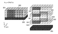
- FIG. 4 is a diagram illustrating an example of a three-dimensional model in which the monitoring area scanned by the three-dimensional laser scanner 10 is represented as a virtual three-dimensional space in the first embodiment. That is, FIG. 4 is a diagram illustrating an example of a three-dimensional model in which each grid in the field of view of the three-dimensional laser scanner 10 expressed in two dimensions is assembled as a virtual three-dimensional space in the first embodiment.
- FIG. 4 shows a three-dimensional model obtained by dividing a virtual three-dimensional space representing a monitoring area into 8 ⁇ 4 ⁇ 4 cubes. Each cube represents a point or region in a virtual three-dimensional space that can be measured by laser irradiation of one point.
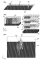
- FIG. 5 shows an example of how the floor 303, the target A301, and the target B302 in the monitoring area look in the solid model divided into 8 ⁇ 4 ⁇ 4 cubes in the first embodiment. It is the figure shown as.
- the individual objects such as the object A301 and the object B302 are collectively referred to as the object 201.
- FIG. 5A is an image diagram showing a positional relationship of the three-dimensional laser scanner 10 and the target A301 and the target B302 as viewed from the side.
- FIG. 5B is a three-dimensional model in which 8 ⁇ 4 ⁇ 4 cubes are in close contact with each other on the left side of the drawing, and a solid model in which 8 ⁇ 4 ⁇ 4 cubes are in close contact, as shown on the left side in the drawing on the right side of the drawing. It is a three-dimensional model in which the model is sliced into four sides so that all the cubes can be seen.
- FIG. 5C is an image diagram of an image obtained by the three-dimensional laser scanner 10 scanning the monitoring area. In the first embodiment, as shown in FIG. 5A, there are a plurality of objects 201 in the monitoring area, and the plurality of objects 201 are located apart in the monitoring area.
- the plurality of objects 201 appear to overlap at least partially on the image viewed from the viewpoint of the three-dimensional laser scanner 10.
- FIG. 5 shows an example in which the target 201 includes two targets A301 and B302, the present invention is not limited to this, and the target 201 may be three or more.
- cubes other than the cubes corresponding to the floor 303, the target A301, and the target B302 are cubes for which distance data could not be obtained by the three-dimensional laser scanner 10.
- the grid data other than the grid corresponding to the floor 301, the target A 301, and the target B 302 has distance data obtained by the three-dimensional laser scanner 10. It was a grid that was not made.
- a grid for which distance data cannot be obtained in the three-dimensional laser scanner 10 is also referred to as a blank grid 304.
- each part of the floor 303 appears higher in the image as the distance from the three-dimensional laser scanner 10 increases in the Z-axis direction due to the depression angle of the three-dimensional laser scanner 10.
- the target A301 and the target B302 are separated from each other in terms of the distance in the Z-axis direction, they appear to overlap in the image obtained by scanning the monitoring area by the three-dimensional laser scanner 10.
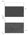
- FIG. 6 is a diagram illustrating the current data that the current data calculation unit 20 stores in the current data storage unit 21 in the first embodiment.
- FIG. 6A is an image diagram of an image indicated by current data.
- FIG. 6B is a diagram illustrating an example in which the image diagram of the image indicated by the current data in FIG. 6A is divided into grids and the numbers indicated by the current data are added.
- an image obtained by scanning the monitoring area by the three-dimensional laser scanner 10 is divided into 19 grids in the Y-axis direction ⁇ 24 grids in the X-axis direction.
- the number indicated by the current data is the distance from the three-dimensional laser scanner 10.
- the distance from the three-dimensional laser scanner 10 is in the range of 0 to 15 m, and the distance is indicated by 0 to F.
- the unit of the distance indicated by 0 to F is m.
- the current data of the object A301 is occupied in a range of 3 m ⁇ 1 m, and the object A301 is present at a position where the distance from the three-dimensional laser scanner 10 is about 3 m. .
- the current data of the target B302 is occupied by a range of 9 m ⁇ 1 m, and the target B302 indicates that the distance from the three-dimensional laser scanner 10 exists at a position of about 9 m. Yes.
- both are fluctuation values that change when the target A301 or the target B302 moves in the Z-axis direction.
- the floor 303 is spread evenly in the range of 1 to 15 m.
- a blank grid 304 indicates a pixel for which distance data has not been obtained, and is treated on the assumption that the distance is “F” in subsequent calculations.
- FIG. 7 is a diagram illustrating comparison data that the comparison data calculation unit 30 stores in the comparison data storage unit 31 in the first embodiment.
- FIG. 7A is an image diagram of an image indicated by the comparison data
- FIG. 7B is a diagram illustrating an example in which the image diagram indicated by the comparison data in FIG. 7A is divided into grids and numbers indicated by the comparison data are added. .
- the number indicated by the comparison data is the distance from the three-dimensional laser scanner 10.
- the distance from the three-dimensional laser scanner 10 is in the range of 0 to 15 m, and the distance is indicated by 0 to F.
- the unit of the distance indicated by 0 to F is m. Since the target A301 and the target B302 are the moving target 201, when the comparison data calculation unit 30 generates the comparison data, the target A301 and the target B302 are deleted in the comparison data generation logic, as shown in FIG. 7B.
- the comparison data is created as data indicating only the floor 303 where the value of the distance data is stable. In FIG. 7B, the floor 303 is spread evenly in the range of 1 to 15 m.
- the change area extraction unit 40 calculates the difference value by comparing the current data as shown in FIG. 6 with the comparison data as shown in FIG. 7 in units of grids, and the calculated difference value is preset. A pixel area that is equal to or greater than the threshold is extracted as a change area.
- the change area extraction unit 40 calculates the difference value by comparing the current data as illustrated in FIG. 6 and the comparison data as illustrated in FIG. 7 in units of grids. It is the figure which showed the result as an example.
- FIG. 8A is an image diagram showing an image obtained as a result of calculating a difference value between the current data as shown in FIG. 6B and the comparison data as shown in FIG. 7B.
- FIG. 8B is a diagram showing a result of calculating a difference value between the current data as shown in FIG. 6B and the comparison data as shown in FIG. 7B.
- the difference value between the current data and the comparison data is shown as an absolute value. That is, the numbers added to FIG.
- the distance from the three-dimensional laser scanner 10 is in the range of 0 to 15 m, and the distance is indicated by 0 to F.
- the unit of the distance indicated by 0 to F is m.
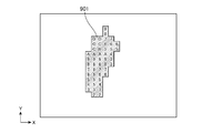
- FIG. 9 is a diagram illustrating a result of extracting the change region based on the difference value after the change region extraction unit 40 calculates the difference value as illustrated in FIG. 8 in the first embodiment.
- the change area extraction unit 40 extracts the grid as a change area when the difference value between the current data and the comparison data is “2” or more in each grid. It is supposed to be.
- the grid extracted as the change area by the change area extraction unit 40 is shown as a change area 901.
- the difference values between the current data and the comparison data are appended as numbers to each grid included in the change area 901, as in FIG. 8B.
- the change area extraction unit 40 acquires the current data accumulated in the current data accumulation unit 21 and the comparison data accumulated in the comparison data accumulation unit 31, and the current data and the comparison data are obtained in units of grids. A difference value is calculated by comparison, and a pixel region in which the calculated difference value is equal to or greater than a preset threshold value is extracted as a change region. The change area extraction unit 40 outputs the extracted change area information to the front image creation unit 70.
- the front image generation unit 70 Based on the change area information output from the change area extraction unit 40, the front image generation unit 70 generates a front viewpoint image in which the change area is indicated by a pixel area on the image indicating the monitoring area. Specifically, the front image creation unit 70 extracts only the grid corresponding to the change region from the grid in the image indicated by the current data based on the change region information output by the change region extraction unit 40, A front viewpoint image consisting only of the grid is created. When the front viewpoint image is visualized, an image similar to that shown in FIG. 9 is obtained. However, although the numbers added in FIG.
- the front image creation unit 70 outputs information on the front viewpoint image to the coordinate conversion unit 80 and the front image labeling unit 100.
- the monitoring apparatus 1000 includes the front image creation unit 70, and the front image creation unit 70 is based on the change area information output from the change area extraction unit 40.
- the front image creation unit 70 is created.
- the monitoring apparatus 1000 does not include the front image creation unit 70, and the coordinate conversion unit 80 and the front image labeling unit 100, which will be described later, are based on the current data and the information on the change area extracted by the change area extraction unit 40.
- the data and the information on the change area may be combined and regarded as a front viewpoint image.
- the change area extraction unit 40 outputs the current data and the change area information to the coordinate conversion unit 80 and the front image labeling unit 100.
- the coordinate conversion unit 80 and the front image labeling unit 100 combine the current data output from the change region extraction unit 40 and the information of the change region into a front viewpoint image, and perform processing described later.
- the coordinate conversion unit 80 creates an image in which the viewpoint of the front viewpoint image is moved based on the information of the front viewpoint image output from the front image creation unit 70.
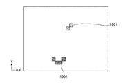
- FIG. 10 is a diagram illustrating an image of the overhead viewpoint image as a result of the coordinate conversion unit 80 performing coordinate conversion from the front viewpoint image to the overhead viewpoint image in the first embodiment.
- the coordinate conversion unit 80 performs coordinate conversion on the front viewpoint image with the depth direction in the front viewpoint image as the Y axis direction and the X axis direction in the front viewpoint image as it is as the X axis direction.
- the depth direction in the front viewpoint image corresponds to the Z-axis direction in the monitoring area.
- the target A301 exists at a position of about 3 m from the three-dimensional laser scanner 10 and the target B302 exists at a position of about 9 m from the three-dimensional laser scanner 10 (see FIG. 6).
- the distance 3m from the three-dimensional laser scanner 10 to the target A301 and the distance 9m from the target B302 are set as coordinates on the Y axis, respectively, and the change area is reprojected with the current coordinates on the X axis as they are. That is, the coordinate conversion by the coordinate conversion unit 80 in the first embodiment is an exchange of the Z-axis information and the Y-axis information of the distance data in the point cloud data 17.
- the pixel area created by the coordinate conversion unit 80 performing the coordinate conversion of the change area as shown in FIG. 10 is also referred to as a post-conversion change area.
- An image indicating the post-change area is also referred to as a directly above viewpoint image. That is, in the first embodiment, the directly overhead viewpoint image is an image obtained by moving the viewpoint of the three-dimensional laser scanner 10 to the viewpoint in the upward direction with respect to the front viewpoint image created by the front image creation unit 70. It is an image converted in this way.
- the post-conversion change area see 1002 in FIG.
- the coordinate conversion unit 80 outputs information on the directly-upper viewpoint image indicating the changed area after conversion to the directly-upward image labeling unit 90.
- the direct image labeling unit 90 performs labeling of each grid included in the post-conversion change region based on the information of the direct top viewpoint image indicating the post-conversion change region output from the coordinate conversion unit 80.
- the front image labeling unit 100 labels each grid included in the change region based on the information of the front viewpoint image indicating the change region output from the front image creation unit 70.
- the change area and the post-conversion change area indicated by the front viewpoint image and the directly-upper viewpoint image are areas formed by a grid in which the difference value between the current data and the comparison data is extracted by the change area extraction unit 40 and is equal to or greater than a threshold value. It is an area based on However, the grids in the region are independent in the directly-upper viewpoint image and the front viewpoint image. However, the change region and the post-conversion change region occur with respect to the target A 301 or the target B 302 that is the target object 201 that originally exists in the field of view of the three-dimensional laser scanner 10. Therefore, although the grids of the change area and the post-conversion change area are independent, each grid originally belongs to either the target A301 or the target B301.
- the directly-upward image labeling unit 90 determines the grids belonging to the same object 201 for the grids included in the post-conversion change area indicated by the directly-upper viewpoint image, collects them into one aggregate, and labels each aggregate. Is granted. Further, the front image labeling unit 100 discriminates the grids belonging to the same object 201 with respect to the grids included in the change area indicated by the front viewpoint image, collects them into one aggregate, and assigns a label to each aggregate. To do.
- the operation in which the image image labeling unit 90 and the front image labeling unit 100 combine the grids into one aggregate and assign labels to the aggregates is referred to as labeling in the first embodiment.
- the immediately upper image labeling unit 90 and the front image labeling unit 100 determine a grid that belongs to the same object 201 from among the converted areas in the converted area and the changed area, and belong to the same object 201.
- the same label number is assigned to each determined grid.
- each object 201 is given a different label number.
- the labeling operation performed by the upper image labeling unit 90 and the front image labeling unit 100 will be described in detail.
- the labeling performed by the directly above image labeling unit 90 and the front image labeling unit 100 is labeling on a grid on the image, so that it is distinguished from labeling operation in a three-dimensional space, which will be described later, particularly two-dimensional labeling. To do. Labeling in a three-dimensional space described later is referred to as three-dimensional labeling.
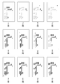
- FIG. 11 is a diagram for explaining an example of a labeling operation procedure performed by the front image labeling unit 100 in the first embodiment.
- the labeling operation will be described as an example of a labeling operation procedure performed by the front image labeling unit 100 with reference to FIG.
- the procedure of the labeling operation performed by the direct image labeling unit 90 is the same as the procedure of the labeling operation performed by the front image labeling unit 100, and whether the target to be labeled is a grid included in the change region or included in the converted change region. The only difference is the grid. Therefore, a detailed description of the labeling operation performed by the upper image labeling unit 90 is omitted.
- a grid indicated by a black square represents an example of a grid included in the change area indicated by the front viewpoint image created by the front image creation unit 70 based on the change area information extracted by the change area extraction unit 40.
- FIG. 11 shows an example in which a grid of change areas is arranged for the sake of simplifying the explanation of the labeling operation. Note that the example shown in FIG. 11 is an example of a change region 901 different from the example shown in FIG.
- the front image labeling unit 100 starts a raster scan by searching the grid of the change area from the upper left of the front viewpoint image (see FIG. 11A).
- the search portion that is the target of raster scanning is indicated by a white square. Since the raster scan performed by the front image labeling unit 100 is a general existing raster scan, detailed description thereof is omitted.
- the front image labeling unit 100 finds the grid in the first change area, the front image labeling unit 100 assigns the label “1” to the encountered grid (see FIG. 11B). The front image labeling unit 100 continues the raster scan. Then, when the newly found change area grid is adjacent to a grid that has already been assigned a label number, the front image labeling unit 100 assigns the same label number as the already assigned label number to the found grid. (See FIG. 11C).
- the adjacent grid is, for example, a grid in which the difference between the X coordinates and the difference between the Y coordinates are both within ⁇ 1.
- adjacent grids may be grids in which the difference between the X coordinates and the difference in the Y coordinates are both within ⁇ 2, and up to which range of grids are considered as adjacent grids, It can be appropriately set in advance.
- the front image labeling unit 100 since the front image labeling unit 100 has found a grid adjacent to the grid that has already been assigned the label number “1”, the front image labeling unit 100 shows a state in which the label “1” has been assigned to the found grid.
- the front image labeling unit 100 continues the raster scan.
- the front image labeling unit 100 assigns a label number different from the already assigned label number to the found grid when the newly found grid of the changed area is not adjacent to the already assigned grid number. (See FIG. 11D).
- FIG. 11D the front image labeling unit 100 has found a grid that is not adjacent to the grid that has already been assigned the label number “1”, and thus shows a state in which the label “2” has been assigned to the found grid.
- the front image labeling unit 100 continues the raster scan. Then, the front image labeling unit 100 further determines that, if the newly found grid of the changed area is not adjacent to the grid that has already been assigned a label number, the label number that is different from the label number that has already been assigned to the found grid. (See FIG. 11E). In FIG. 11E, the front image labeling unit 100 has found a grid that is not adjacent to any of the grids that have already been assigned the label numbers “1” or “2”, and therefore has assigned the label “3” to the found grid. Indicates the state.
- the front image labeling unit 100 finishes the raster scan for the first line, the front image labeling unit 100 proceeds to the raster scan for the second line (see FIG. 11F).
- the front image labeling unit 100 performs a raster scan of the second line, and assigns a label number to the grid of the change area, as in the first line. Then, the front image labeling unit 100 shifts to the raster scan of the third line when the raster scan of the second line is completed (see FIG. 11G).
- the front image labeling unit 100 determines that the newly found grid of the changed region is a grid adjacent to a plurality of grids that have already been assigned different label numbers (see FIG. 11H).
- FIG. 11H while the front image labeling unit 100 is executing the raster scan of the third line, the grid adjacent to both the grid already assigned with the label number “1” and the grid assigned with “2” is displayed. Indicates the discovered state. In this case, at this point, it has been found that both the grid assigned the label number “1” and the grid assigned the label number “2” belong to the same object 201.
- the front image labeling unit 100 is assigned the same label number for the grid assigned the label number “1” and the grid assigned the label number “2”, which are found to belong to the same object 201. To. Specifically, the front image labeling unit 100 changes the label number of the grid to which the label number “2” is assigned to “1” and unifies the label number “1” (see FIG. 11I). Note that this is merely an example, and for example, the front image labeling unit 100 may change the label number of the grid to which the label number “1” is assigned to “2”. It suffices that the same label number is given to the grids of the change areas that are found to belong to the same object 201.
- the front image labeling unit 100 continues the raster scan and shifts to the sixth line raster scan. It is assumed that a new grid of a change area is found on the sixth line, but it is determined that the grid is a grid adjacent only to a grid already assigned with one label number. For example, it is assumed that the newly found grid of the change area is a grid that is adjacent only to the grid already assigned the label number “1”. In this case, the front image labeling unit 100 assigns the label number “1” to the newly discovered grid, and the grid already assigned the label number, for example, the grid assigned the label number “3”. The label number is not changed (see FIGS. 11J to 11K).
- the front image labeling unit 100 performs the labeling operation according to the above procedure. As a result, for example, labeling is performed on the grid included in the change area indicated by the front viewpoint image in the state shown in FIG. 11A, and the label number “ 1 ”and label number“ 3 ”are assigned.
- the front image labeling unit 100 is included in the change area 901 indicated by the front viewpoint image as shown in FIG. 9 according to the labeling procedure as described with reference to FIG. 11. It is a figure which shows an example of the result of having performed labeling on the grid. In FIG. 12, the assigned label numbers are added to each labeled grid.
- the same label number “1” is assigned to all the grids extracted as the change area 901.
- the grid included in the target A301 and the grid included in the target B are mixed.
- the unit 100 assigns the same label number to the grid included in the target A301 and the grid included in the target B302.
- FIG. 13 shows the post-conversion change area indicated by the overhead image as shown in FIG. 10 according to the labeling procedure as described with reference to FIG. It is a figure which shows an example of the result of having performed the labeling to the grid contained in 1001,1002.
- each labeled label is given a label number.
- the labeling by the directly above image labeling unit 90 is a two-dimensional labeling, but the target of the two-dimensional labeling is a directly above viewpoint image.
- the grids included in each of the objects 201 are separated and arranged so that the distance between the objects 201 can be understood. Specifically, as shown in FIG. 10, the grid included in the post-conversion change area 1002 indicating the target A301 and the grid included in the post-conversion change area 1001 indicating the target B302 are arranged separately. . Therefore, for example, as illustrated in FIG.
- the immediately upper image labeling unit 90 assigns the label number “1” to the grid included in the post-conversion change area (see 1301 in FIG. 13) indicating the target B302, and the target A301.
- the label number “2” is assigned to the grid of the post-conversion change area (see 1302 in FIG. 13).
- the directly above image labeling unit 90 and the front image labeling unit 100 are included in the grid included in the post-conversion change area indicated by the immediately above viewpoint image and the change area indicated by the front viewpoint image, respectively. Label the grid.
- the immediately upper image labeling unit 90 sets the post-conversion change area to which the label number information is added as a post-conversion change area with label, and outputs the information on the directly above viewpoint image indicating the post-conversion change area with label to the label dividing section 110 To do.
- the front image labeling unit 100 outputs the information on the front viewpoint image indicating the labeled change area to the label dividing unit 110 by using the change area to which the label number information is added as the labeled change area.
- the label dividing unit 110 includes information on the directly-upper viewpoint image indicating the post-conversion change area with label output from the immediately-up image labeling section 90, and information on the front viewpoint image indicating the change area with label output from the front image labeling section 100. Based on the above, the label numbers assigned to the respective grids included in the labeled change area indicated by the front viewpoint image are distributed for each object 201.
- the directly-upper viewpoint image indicating the post-conversion change area with the label based on the information output from the immediately-up image labeling unit 90 is the directly-upper viewpoint image as illustrated in FIG. 13, and the information output from the front image labeling unit 100.
- the front viewpoint image indicating the labeled change area based on the above will be described below assuming that it is a front viewpoint image as shown in FIG.
- the label division unit 110 compares the directly-upper viewpoint image indicating the post-conversion converted change area and the front viewpoint image indicating the labeled change area.
- the grid included in the target A301 see 1302 in FIG. 13
- the grid included in the target B302 among the grids in the converted changed area. (Refer to 1301 in FIG. 13)
- different label numbers “1” or “2” are assigned respectively.
- the grid included in the target A301 and the grid included in the target B302 are not separated from the grid in the labeled change area 1201 and are the same.
- the label number “1” is assigned.
- the label dividing unit 110 compares the directly-upper viewpoint image indicating the post-conversion change area with the front view image indicating the label change area with the X-axis aligned, and includes each of the change areas after the label conversion. Based on the label number assigned to the grid, the grid included in the target A301 and the grid included in the target B302 that are mixed in each grid included in the labeled change area are separated, and Reassign the label number.
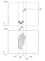
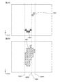
- FIGS. 14 and 15 are diagrams for explaining a specific operation in which the label dividing unit 110 reassigns a label number to each grid included in the labeled change area in the first embodiment.
- FIG. 14A and FIG. 15A show images of viewpoint images immediately above that show post-conversion converted changed areas 1301 and 1302.
- each grid included in the post-conversion post-conversion change areas 1301 and 1302 is labeled with a label number assigned by the immediately above image labeling unit 90.
- FIG. 14B is an image of a front viewpoint image showing a labeled change area, and each grid included in the labeled change area 1201 has a label number given by the front image labeling unit 100 appended thereto.
- FIG. 15B is an image of the front viewpoint image showing the labeled change area 1501 after the label dividing unit 110 assigns the label number again.
- Each grid included in the labeled change area 1501 includes label division. The label number reassigned by the section 110 is added.
- the label dividing unit 110 discriminates the positions of both ends of the target A301 in the X-axis direction and the positions of both ends of the target B302 in the X-axis direction from the viewpoint image (FIG. 14A). To do.
- the positions of both ends of the target A301 and the positions of both ends of the target B302 can be determined from the label numbers assigned to the grids of the post-conversion converted change areas 1301 and 1302.
- the grid included in the target A301 is a grid to which the label number “2” is assigned (see 1302 in FIG. 14), and the grid included in the target B302 is assigned the label number “1”. Grid (see 1301 in FIG. 14).
- the label dividing unit 110 sets a straight line that passes through the positions of both ends of the identified target A301 and the positions of both ends of the target B302 on the immediately above viewpoint image and intersects the X axis perpendicularly.
- four straight lines passing through the left end of the target A301, the right end of the target A301, the left end of the target B302, or the right end of the target B are set along the X axis.
- the four straight lines are indicated by an A left dotted line 1401, an A right dotted line 1402, a B left dotted line 1403, and a B right dotted line 1404, respectively.
- the A right dotted line 1402 and the B left dotted line 1403 overlap.
- the label dividing unit 110 sets the A left dotted line 1401, the A right dotted line 1402, the B left dotted line 1403, and the B right dotted line 1404 set on the overhead viewpoint image at the same position as the X axis position on the overhead viewpoint image.
- each is also set on the front viewpoint image (FIG. 14B).
- FIG. 12 since all the grids in the labeled change area 1201 are assigned the same label number, the grid included in the target A301 and the grid included in the target B302 are not separated. However, according to the straight line set on the front viewpoint image, the positions of the grid included in the target A301 and the grid included in the target B302 can be determined in the labeled change area 1201.
- the label dividing unit 110 includes the grid in the labeled change area 1201 in the target A301 in accordance with the A left dotted line 1401, the A right dotted line 1402, the B left dotted line 1403, and the B right dotted line 1404.
- the grid is separated into the grid included in the target B302, and the label numbers are reassigned so that the target 201 has a different label number.
- the label dividing unit 110 uses the label number assigned to the grid included in the labeled change area 1501 as the label number assigned to the grid of the post-conversion converted change areas 1301 and 1302. Try to match. Specifically, the label dividing unit 110 reassigns the label numbers so that the label number of the grid included in the target A301 is “2” and the label number of the grid included in the target B302 is “1”. This is merely an example, and the label dividing unit 110 includes grids included in different objects 201 determined based on the label numbers assigned to the grids included in the post-conversion converted change areas 1301 and 1302. For each object 201 included, a label number may be reassigned.
- the label dividing unit 110 sets a change area with a label to which a label number reassigned to each grid is assigned as a change area with a fixed label, and uses information on a front viewpoint image indicating the change area with a fixed label as an object identification To the unit 120.
- the target object identification unit 120 identifies the target object 201 existing in the field of view of the three-dimensional laser scanner 10 based on the information of the front viewpoint image indicating the change area with a definite label output from the label division unit 110. Specifically, for example, when the information of the front viewpoint image indicating the change area 1501 with a fixed label as illustrated in FIG. 15B is output from the label dividing unit 110, the object identification unit 120 includes the change area with the fixed label. Based on the label number assigned to the grid included in 1501, two types of label numbers, label number “1” and label number “2”, are assigned, so that 2 exists in the field of view of the three-dimensional laser scanner 10. One object 201 is identified. Then, the object identification unit 120 sets the ferret diameter so as to include the grid included in the same object 201.
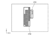
- FIG. 16 is a diagram illustrating an example in which the object identification unit 120 sets the ferret diameter in the grid included in the change area with a definite label in the first embodiment.
- region with a definite label to which the ferret diameter was set is shown.
- the object identification unit 120 sets a circumscribed rectangle for each of the grid assigned the label number “1” and the grid assigned the label number “2”, and the first ferret diameter 1601 is set. , And a second ferret diameter 1602 are set.
- the circumscribed rectangle of the grid to which the label number “1” is assigned is the first ferret diameter 1601
- the circumscribed rectangle of the grid to which the label number “2” is assigned is the second ferret diameter 1602. That is, the grid included in the target A301 is separated as the second ferret diameter 1602, and the grid included in the target B302 is separated as the first ferret diameter 1601.
- the object identification unit 120 uses, as a recognition target area, a change area with a definite label to which information on the first ferret diameter 1601 and the second ferret diameter 1602 is added, and information on the front viewpoint image indicating the recognition target area.
- the data is output to the recognition processing unit 50.
- the current data indicating the visual field of the three-dimensional laser scanner 10 is compared with the comparison data on the two-dimensional image, and the change region is determined based on the difference of the distance data. Is extracted, and information on the changed area after conversion is generated by coordinate-converting the changed area.
- the monitoring apparatus 1000 labels each of the grid included in the change area and the grid included in the post-conversion change area by two-dimensional labeling, and uses the result of two-dimensional labeling the grid included in the post-conversion change area, As a result of two-dimensional labeling of the grid included in the change area, when the same label number is assigned to a plurality of different objects 201, the label is assigned so that the label numbers are assigned to the different objects 201. Reassign the number. Thereby, the object 201 can be determined in consideration of the perspective difference even by two-dimensional labeling.
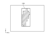
- FIG. 17 is a diagram for determining the object 201 based only on the result of two-dimensional labeling of the grid included in the change area without using the result of two-dimensional labeling of the grid included in the changed area after conversion. It is a figure which shows an example of the image of the front viewpoint image which shows a change area
- FIG. 17 shows an example in which the object 201 is determined based on a labeled change area 1201 that is a result of two-dimensional labeling of a grid included in the change area as shown in the front viewpoint image shown in FIG. It is said. In the front viewpoint image shown in FIG.
- the same label number “1” is given to the grid of the labeled change area 1201 even though the object A301 and the object B302 are included.
- the object 201 is determined only from the two-dimensional labeling result of the labeled change area 1201 indicated by the front viewpoint image, only one object 201 is determined and only one ferret diameter is set (1701 in FIG. 17). reference). This is because the perspective difference between the position where the target A301 exists and the position where the target B302 exists cannot be determined only from the labeled change area 1201 shown in the front viewpoint image.
- the post-conversion change area indicated by the immediately above viewpoint image that can determine the perspective difference between the position where the target A301 exists and the position where the target B302 exists.
- the target object 201 including the grid in the change area is discriminated using the change area after conversion.
- the three-dimensional labeling technique instead of the two-dimensional labeling, it is possible to determine the perspective difference of the different objects 201, so that two objects A301 that exist in overlapping positions when viewed from the front and Even when the target B 302 exists (see FIG. 5C), each can be identified using the distance data.
- a conventional method for determining a plurality of objects 201 using a general three-dimensional labeling technique will be briefly described below.
- FIG. 5C A conventional method for determining a plurality of objects 201 using a general three-dimensional labeling technique
- the floor 303, the target A301, and the target B302 in the field of view of the three-dimensional laser scanner 10 are represented as a part of 8 ⁇ 4 ⁇ 4 cubes (
- the target A301 and the target B302 are identified by three-dimensional labeling based on the distance data for each cube.
- the adjacent cubes in the depth direction are subject to labeling.
- the found change area cube is a cube adjacent to a cube that has already been assigned a label number
- the same label number is assigned to the found change area cube.
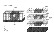
- FIG. 18 is a diagram for explaining an example of a search range as to whether or not a cube already assigned a label number is adjacent to a discovered change area cube.
- adjacent cubes are cubes in which the difference between the X coordinate, the difference in the Y coordinate, and the difference in the Z coordinate are within ⁇ 1.
- a cube 1801 and a cube adjacent to the target cube 1801 are shown as adjacent cubes 1802. If there is a cube already assigned a label number in the adjacent cube 1802, the same cube number as the adjacent cube 1802 already assigned the label number is assigned to the target cube 1801.
- FIG. 19 shows the result of identifying the object 201 for the cube model as shown in FIG. 5 based on the concept described above with reference to FIG.
- the label number “1” is assigned to the cube included in the target A301
- the label number “2” is assigned to the cube included in the target B302. That is, it is possible to identify that the cube in the change target region is a cube included in the two objects 201 by the three-dimensional labeling.
- the circumscribed rectangle of the cube to which the label number “1” is assigned that is, the cube included in the target A301, is set as the first ferret diameter 1901.
- the circumscribed rectangle of the cube to which the label number “2” is assigned, that is, the cube included in the target B302 is set as the second ferret diameter 1902.
- the object 201 is identified by the three-dimensional labeling method using the distance data, the object A301 and the object B302 can be identified as different objects 201.
- the object A301 and the object B302 can be identified as different objects 201.
- the number of adjacent cubes 1802 adjacent to the target cube 1801 is 26 in total. That is, in the three-dimensional labeling method, for example, when the adjacent cubes are within ⁇ 1 in X, Y, and Z coordinates, one attention cube 1801 must be compared 26 times without performing one comparison operation. The three-dimensional labeling operation of the cube 1801 is not completed.
- an object to be labeled in this case, the target grid
- the cube or grid within the range of ⁇ 1 from the target cube or grid is the target of the comparison operation.
- the range of the cube or grid that is the target of the comparison operation is further expanded.
- the difference in the amount of calculation further widens. For example, if the target cube or grid within the range of ⁇ 2 from the target grid is the target of the comparison operation, in the three-dimensional labeling, there are 124 adjacent cubes, and 124 comparisons are made for one target cube. Calculation is required.
- the object 201 is identified using the three-dimensional labeling method, the presence or absence of contact on the Z coordinate can be identified at the same time.
- a calculation amount of three times or five times that of the two-dimensional labeling is required, and there is a problem that the calculation cost is higher than that of the two-dimensional labeling.
- the monitoring apparatus 1000 by creating a post-conversion change region, the presence or absence of contact on the Z coordinate is considered based on the distance data, and the target is obtained by a two-dimensional labeling technique.
- the object 201 can be identified. That is, the monitoring apparatus 1000 according to the first embodiment can identify an object with a reduced amount of calculation using the distance difference and without performing three-dimensional labeling.
- the recognition processing unit 50 Based on the information of the front viewpoint image indicating the recognition target region output from the object identification unit 120, the recognition processing unit 50 has characteristics such as “area”, “vertical / horizontal dimension”, “speed”, etc. An amount is extracted, and recognition processing is performed to determine whether or not the change region is a notification target based on whether or not the extracted feature amount satisfies a predetermined condition.
- the recognition processing unit 50 recognizes that the change area is a notification target, the recognition processing unit 50 outputs notification instruction information to the notification processing unit 60.
- the notification processing unit 60 performs notification processing based on the notification instruction information output from the recognition processing unit 50. Examples of the notification process include a process of transmitting a specific signal to an upper apparatus such as the PC 300, or a process of causing the apparatus to sound a buzzer.
- the three-dimensional laser scanner 10 is provided in the monitoring apparatus 1000.
- the present invention is not limited to this, and the three-dimensional laser scanner 10 is provided outside the monitoring apparatus 1000.
- the monitoring device 1000 may be configured to acquire the point cloud data 17 from the three-dimensional laser scanner 10 via a network or the like.
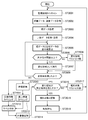
- FIG. 20 is a flowchart showing the operation of the monitoring apparatus 1000 according to the first embodiment.
- the three-dimensional laser scanner 10 scans the background 200, that is, the range of the monitoring area (step ST2001), and acquires point cloud data 17, that is, distance data and intensity data (step ST2002).
- the range of the background 200 is divided into 24 ⁇ 19, which is the resolution of the three-dimensional laser scanner 10, and scanned.
- the distance data is generally digital data, and here, multi-value data of 8 bits per pixel of 24 ⁇ 19 pixels is used.
- the three-dimensional laser scanner 10 outputs the acquired point cloud data to the current data calculation unit 20 and the comparison data calculation unit 30.
- the current data calculation unit 20 accumulates the distance data in the point cloud data 17 of 24 ⁇ 19 pixels acquired in step ST2002 in the current data accumulation unit 21 as current data (step ST2003).
- the image of the current data is as shown in FIG. In FIG. 6B, distance data is appended to each grid.
- the comparison data calculation unit 30 converts distance data in the point group data 17 of 24 ⁇ 19 pixels acquired in step T2002 in the past and stored in a data storage unit (not shown) into comparison data, and the comparison data storage unit 31 (Step ST2004).
- the image of the comparison data is as shown in FIG. In FIG. 7B, distance data is appended to each grid.
- the change area extraction unit 40 acquires the current data accumulated in the current data accumulation unit 21 and the comparison data accumulated in the comparison data accumulation unit 31, compares the current data with the comparison data in units of grids, and calculates a difference value. Is calculated (see FIG. 8), and a pixel region whose calculated difference value is equal to or greater than a preset threshold is extracted as a change region (see step ST2005, FIG. 9).
- the difference value calculated by the change region extraction unit 40 indicates “distance difference”. For example, when the background data 200 and the object 201 are included in the current data, and only the background 200 is included in the comparison data, the obtained difference value is “distance between the background of the comparison data and the object of the current data”. Is shown.
- the difference value obtained in step ST2005 is 8-bit multi-value data per pixel, and the change area extraction unit 40 determines whether or not the obtained difference value is equal to or greater than a preset threshold value (step ST2006). ). If the difference value is equal to or greater than the threshold value (in the case of “YES” in step ST2006), the pixel area is extracted as a change area (step ST2007).
- the change area extraction unit 40 outputs the extracted change area information to the front image creation unit 70.
- the front image creation unit 70 creates a front viewpoint image in which the change area is indicated by a pixel area on the image indicating the monitoring area based on the change area information output from the change area extraction unit 40. Information on the viewpoint image is output to the coordinate conversion unit 80 and the front image labeling unit 100.
- step ST2008 determines whether or not processing has been performed for all 24 ⁇ 19 pixels (step ST2009). When the process is not performed for all 24 ⁇ 19 pixels (in the case of “NO” in step ST2009), the process returns to step ST2005 and the above-described process is repeated.
- the coordinate conversion unit 80 is based on the information of the front viewpoint image output from the front image creation unit 70 in step ST2007.
- An image in which the viewpoint of the front viewpoint image is moved is created (step ST2010). The specific operation is as described with reference to FIGS.
- the coordinate conversion unit 80 outputs information on the viewpoint image immediately above the changed area after conversion to the image labeling unit 90 immediately above.
- the front image labeling unit 100 labels each grid included in the change region based on the information of the front viewpoint image indicating the change region output from the front image creation unit 70 in step ST2007. (Step ST2011). The specific operation is as described with reference to FIGS.
- the front image labeling unit 100 outputs information on the front viewpoint image indicating the labeled change area to the label dividing unit 110.
- the direct image labeling unit 90 performs labeling of each grid included in the post-conversion change region based on the information of the direct top view image indicating the post-conversion change region output from the coordinate conversion unit 80 in step ST2010 (step ST2012). The specific operation is as described with reference to FIGS.
- the directly above image labeling unit 90 outputs information on the directly above viewpoint image indicating the post-conversion converted change area to the label dividing unit 110.
- the label dividing unit 110 outputs the information on the directly-upper viewpoint image indicating the post-conversion change area with label output from the immediately above image labeling section 90 in step ST2012 and the change area with label output from the front image labeling section 100 in step ST2011. Based on the information of the front viewpoint image to be shown, the label numbers assigned to the respective grids included in the labeled change area indicated by the front viewpoint image are assigned to each object 201 (step ST2013). The specific operation is as described with reference to FIGS.
- the label dividing unit 110 outputs, to the target object identifying unit 120, information on the front viewpoint image indicating the change area with a definite label to which the reassigned label number is assigned.
- the object identifying unit 120 identifies the object 201 existing in the field of view of the three-dimensional laser scanner 10 based on the information of the front viewpoint image indicating the change area with the definite label output from the label dividing unit 110 in step ST2013 ( Step ST2014).
- the specific operation is the same as that described with reference to FIGS.
- the target object identifying unit 120 outputs information on the front viewpoint image indicating the recognition target region to which the ferret diameter information is given to the recognition processing unit 50.
- the recognition processing unit 50 determines “area”, “vertical and horizontal dimensions”, and “speed” from the change area for each fillet diameter. And the like, and it is determined whether or not the extracted feature values satisfy a predetermined condition (step ST2015).
- the recognition processing unit 50 recognizes that the change area is a notification target (step ST2016).
- the recognition processing unit 50 recognizes that the change area is a notification target, the recognition processing unit 50 outputs notification instruction information to the notification processing unit 60.
- the verification condition is not satisfied (in the case of “NO” in step ST2015)
- it is determined that the change area is not a notification target (step ST2017) it is determined that the change area is not a notification target (step ST2017), and the process returns to step ST2001.
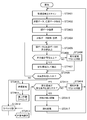
- FIG. 21 is a flowchart showing determination processing by the recognition processing unit 50 of the monitoring apparatus 1000 according to the first embodiment.
- the recognition processing unit 50 determines whether or not a change region belonging to the fillet diameter exists within the monitoring range (step ST2101).
- the monitoring range is a monitoring region, that is, a range within the measurement range of the three-dimensional laser scanner 10, for example, a range in which notification is required when the object 201 is detected due to the necessity of monitoring. It is assumed that the monitoring range is set in advance.
- the recognition processing unit 50 determines whether or not the change area belonging to the fillet diameter has a predetermined area. A determination is made (step ST2102). When the change area belonging to the fillet diameter has a predetermined area (in the case of “YES” in step ST2102), the recognition processing unit 50 further determines that the change area belonging to the fillet diameter has a predetermined vertical and horizontal dimension. It is determined whether or not (step ST2103).
- the recognition processing unit 50 further determines whether or not the change region belonging to the fillet diameter has a predetermined moving speed. (Step ST2104). When it has a predetermined moving speed (in the case of “YES” in step ST2104), the process proceeds to step ST2016 in FIG. 20 and the change area is recognized as a notification target.
- step ST2101 when the change region belonging to the fillet diameter does not exist within the monitoring range (in the case of “NO” in step ST2101), or when the change region belonging to the fillet diameter does not have a predetermined area (“STEP” in step ST2102). NO ”), or when the change area belonging to the fillet diameter does not have the predetermined vertical and horizontal dimensions (in the case of“ NO ”in step ST2103), or the change area belonging to the fillet diameter has a predetermined moving speed. If not (NO in step ST2104), the process proceeds to step ST2017 in FIG. 20 and is determined not to be a notification target.
- the recognition processing unit 50 performs the above-described operation for every fillet diameter for all fillet diameters. Then, if there is a fillet diameter that is determined to be a notification target even if one recognition processing unit 50 exists, the process proceeds to step ST2016 in FIG. 20, and a change region that belongs to the fillet diameter is recognized as a notification target.
- the notification processing unit 60 performs notification processing on the recognized notification target based on the notification instruction information output from the recognition processing unit 50 in step ST2016 (step ST2018), and returns to the process of step ST2001.
- the monitoring apparatus 1000 includes a processing circuit 2201 for performing notification processing when a change to be notified is detected based on the point cloud data acquired from the three-dimensional laser scanner 10.
- the processing circuit 2201 may be dedicated hardware as shown in FIG. 22A or may be a CPU (Central Processing Unit) 2206 that executes a program stored in the memory 2205 as shown in FIG. 22B.
- the processing circuit 2201 includes, for example, a single circuit, a composite circuit, a programmed processor, a parallel programmed processor, an ASIC (Application Specific Integrated Circuit), and an FPGA (Field-Programmable). Gate Array) or a combination of these.
- the processing circuit 2201 is the CPU 2206
- the current data calculation unit 20 the comparison data calculation unit 30, the change area extraction unit 40, the recognition processing unit 50, the notification processing unit 60, the front image creation unit 70, and coordinate conversion
- the functions of the unit 80, the image labeling unit 90, the front image labeling unit 100, the label dividing unit 110, and the object identifying unit 120 are realized by software, firmware, or a combination of software and firmware. .
- the labeling unit 90, the front image labeling unit 100, the label dividing unit 110, and the object identifying unit 120 are a CPU 2206 that executes a program stored in an HDD (Hard Disk Drive) 2202, a memory 2205, a system LSI (Large) -Realized by a processing circuit such as Scale Integration.
- HDD Hard Disk Drive
- LSI Large Scale
- the programs stored in the HDD 2202, the memory 2205, and the like include the current data calculation unit 20, the comparison data calculation unit 30, the change area extraction unit 40, the recognition processing unit 50, the notification processing unit 60, and a front image creation. It can be said that the computer executes the procedures and methods of the unit 70, the coordinate conversion unit 80, the directly above image labeling unit 90, the front image labeling unit 100, the label division unit 110, and the object identification unit 120.
- the memory 2205 is, for example, a RAM (Random Access Memory), a ROM (Read Only Memory), a flash memory, an EPROM (Erasable Programmable Read Only Memory), an EEPROM (Electrically Emmable Memory), or the like. And volatile semiconductor memories, magnetic disks, flexible disks, optical disks, compact disks, mini disks, DVDs (Digital Versatile Discs), and the like.
- a part of the functions of the labeling unit 90, the front image labeling unit 100, the label dividing unit 110, and the object identifying unit 120 are realized by dedicated hardware, and part of the functions are realized by software or firmware. May be.
- the functions of the current data calculation unit 20 and the comparison data calculation unit 30 are realized by a processing circuit 2201 as dedicated hardware, and a change area extraction unit 40, a recognition processing unit 50, and a notification processing unit 60
- the processing circuit is stored in the memory 2205 for the front image creation unit 70, the coordinate conversion unit 80, the directly above image labeling unit 90, the front image labeling unit 100, the label division unit 110, and the object identification unit 120.
- the function can be realized by reading and executing the program.
- the current data storage unit 21 and the comparison data storage unit 31 use an HDD 2202, for example. This is only an example, and the current data storage unit 21 and the comparison data storage unit 31 may be configured by a DVD, a memory 2205, or the like.
- the monitoring apparatus 1000 includes an input interface apparatus 2203 and an output interface apparatus 2204 that communicate with the three-dimensional laser scanner 10 or an upper apparatus such as the PC 300.
- the distance data to the plurality of objects existing in the monitoring area is obtained from the measurement result of the three-dimensional laser scanner 10 that measured the monitoring area, and the current distance data and The current data calculation unit 20 to obtain past distance data from the measurement result, calculate the difference value between the current distance data and the comparison distance data, and the difference value between the current distance data and the comparison distance data.
- the viewpoint of the three-dimensional laser scanner 10 is moved with respect to the front viewpoint image based on the change area extraction unit 40 that extracts a change area that is equal to or greater than the threshold, and the current distance data and the change area extracted by the change area extraction unit 40.
- the label dividing unit 110 uses the information of the immediately above viewpoint image indicating the post-conversion converted change area, and assigns the label number assigned to each grid included in the labeled change area for each target object 201.
- the label numbers were reassigned so that the same label number was assigned to each.
- the label dividing unit 110a does not perform a labeling process in advance on each grid included in the change area, and performs label processing on each grid included in the change area to which no label number is assigned.
- a description will be given of an embodiment in which label numbers are assigned by using information on a viewpoint image immediately above indicating a post-conversion change area.
- FIG. 23 is a block diagram showing a configuration of a monitoring apparatus 1000a according to Embodiment 2 of the present invention.
- the monitoring apparatus 1000a according to the second embodiment is different from the monitoring apparatus 1000 according to the first embodiment in that the front image labeling unit 100 is not provided. Further, the operation of the label dividing unit 110a of the monitoring apparatus 1000a according to the second embodiment is different from the operation of the label dividing unit 110 of the monitoring apparatus 1000 according to the first embodiment.
- the front image creation unit 70 creates a front viewpoint image based on the information on the change area extracted by the change area extraction unit 40
- the information on the front view image is labeled with the coordinate conversion unit 80.
- the data is output to the dividing unit 110a.
- the front image creation unit 70 may not be provided, and the current data and the change area information extracted by the change area extraction unit 40 may be considered as a front viewpoint image.
- the change area extraction unit 40 outputs the current data and information on the change area to the coordinate conversion unit 80 and the label division unit 110a, and the coordinate conversion unit 80 and the label division unit 110a include the change area extraction unit 40.
- the current data output from the information and the information on the change area are combined to form a front viewpoint image, and the operation is performed based on the front viewpoint image.
- the hardware configuration of the monitoring apparatus 1000a according to the second embodiment is the same as the configuration described with reference to FIGS. 22A and 22B in the first embodiment, and thus redundant description is omitted.
- FIG. 24 is a flowchart showing the operation of the monitoring apparatus 1000a according to the second embodiment.
- the operations in steps ST2401 to 2411 and steps ST2413 to 2417 in FIG. 24 are the same as the operations in steps ST2001 to 2010, 2012 and steps ST2014 to 2418 described with reference to FIG. 20 in the first embodiment.
- the description which was made is abbreviate
- the operation of the monitoring apparatus 1000a according to the second embodiment is different only in that the operation of step ST2013 in FIG. 20 described in the first embodiment is the operation of step ST2412. Therefore, only the operation of label division section 110a in step ST2412 different from that in Embodiment 1 will be described below.
- the label dividing unit 110a includes information on the directly-upper viewpoint image indicating the post-conversion change area with label output from the immediately-upper image labeling unit 90 in step ST2411, and information on the front viewpoint image output by the front image creating unit 70 in step ST2407 Based on the above, a label number for each object 201 is assigned to each grid included in the change area (step ST2412).
- the operation of the label division unit 110a in step ST2412 will be described in detail with reference to the drawings.
- the image of the overhead viewpoint image based on the information output from the overhead image labeling unit 90 in step ST2411 is an image of the overhead viewpoint image as shown in FIG. 13, and is output from the front image creation unit 70 in step ST2407.
- the image of the front viewpoint image based on the information will be described below assuming that it is the image of the front viewpoint image as shown in FIG.
- the label dividing unit 110a compares the directly-upper viewpoint image indicating the post-conversion converted change area and the front viewpoint image indicating the change area.
- the grid included in the target A301 see 1302 in FIG. 13
- the grid included in the target B302 among the grids in the converted changed area. (Refer to 1301 in FIG. 13) and different label numbers “1” or “2” are given.
- the grid included in the target A301 and the grid included in the target B302 extracted as the change area 901 are not separated. Further, in the front viewpoint image as shown in FIG.
- the label dividing unit 110 compares the immediately-upper viewpoint image indicating the change area after conversion with the label and the front viewpoint image indicating the change area where labeling is not performed in a state where the X-axis is aligned, and changes after conversion with label. Based on the label number assigned to each grid included in the area, the grid included in the target A301 and the grid included in the target B302 mixed in each grid included in the change area 901 are separated, and the target A label number for each object 201 is assigned.
- FIG. 25 and FIG. 26 are diagrams for explaining a specific operation in which the label dividing unit 110a assigns a label number to each grid included in the change area where labeling is not performed in the second embodiment.
- FIG. 25A and FIG. 26A show the viewpoint images immediately above showing the post-conversion converted changed areas 1301 and 1302.
- each grid included in the post-conversion post-conversion change areas 1301 and 1302 is labeled with the label number assigned by the immediately above image labeling unit 90.
- FIG. 25B is a front view image showing the change area 901, and each grid included in the change area 901 has a distance difference between the current data and the comparison data added as a number.
- FIG. 26B is a front view image showing the change area 901 after the label division unit 110a assigns the label number.
- Each grid included in the change area 901 has the label number assigned by the label division unit 110a. It is added.
- the label dividing unit 110a discriminates the positions of both ends of the target A301 in the X-axis direction and the positions of both ends of the target B302 in the X-axis direction from the viewpoint image (FIG. 25A). To do.
- the positions of both ends of the target A301 and the positions of both ends of the target B302 can be determined from the label numbers assigned to the grids of the post-conversion converted change areas 1301 and 1302.
- the grid included in the target A301 is a grid to which the label number “2” is assigned (see 1302 in FIG. 25A), and the grid included in the target B302 is assigned the label number “1”. Grid (see 1301 in FIG. 25A).
- the label dividing unit 110a sets a straight line that passes through the positions of both ends of the identified target A301 and the positions of both ends of the target B302 on the immediately above viewpoint image and intersects the X axis perpendicularly.
- four straight lines passing through the left end of the target A301, the right end of the target A301, the left end of the target B302, or the right end of the target B are set along the X axis.
- the four straight lines are indicated by an A left dotted line 2501, an A right dotted line 2502, a B left dotted line 2503, and a B right dotted line 2504, respectively.
- the A right dotted line 2502 and the B left dotted line 2503 overlap.
- the label dividing unit 110a sets the A left dotted line 2501, the A right dotted line 2502, the B left dotted line 2503, and the B right dotted line 2504 set on the overhead viewpoint image at the same position as the X axis position on the overhead viewpoint image.
- each is also set on the front viewpoint image (FIG. 25B).
- FIG. 9 no label number is given to any grid in the change area 901, and the grid included in the target A301 and the grid included in the target B302 are not separated.
- the positions of the grid included in the target A301 and the grid included in the target B302 can be discriminated even in such a change area 901.
- the label dividing unit 110a converts the grid in the change area 901 into a grid included in the target A301 according to the A left dotted line 2501, the A right dotted line 2502, the B left dotted line 2503, and the B right dotted line 2504.
- a label number is assigned so as to be separated from the grid included in the object B302 and to have a different label number for each object 201.
- the label dividing unit 110a matches the label number assigned to the grid included in the change area 2601 with the label number assigned to the grid of the post-conversion converted change areas 1301 and 1302. To. Specifically, the label dividing unit 110a assigns label numbers so that the label number of the grid included in the target A301 is “2” and the label number of the grid included in the target B302 is “1”. This is only an example, and the label dividing unit 110a determines the grids included in the different objects 201 determined based on the label numbers assigned to the grids included in the post-conversion converted change areas 1301 and 1302. For each object 201 included, a label number may be given.
- the label dividing unit 110a sets the change area with the label number assigned to each grid as the change area with a definite label, and outputs the information of the front viewpoint image indicating the change area with the definitive label to the target object identification unit 120. To do.
- the object identifying unit 120 identifies the object 201 existing in the field of view of the three-dimensional laser scanner 10 based on the information of the front viewpoint image indicating the change area with a definite label output from the label dividing unit 110a (step ST2413). . Since the specific operation is the same as step ST2014 of FIG. 20 described in the first embodiment, detailed description thereof is omitted, but the object identification unit 120 is included in the same object 201 in step ST2413.
- the ferret diameter is set to include the grid.
- FIG. 27 is a diagram illustrating an example in which the object identification unit 120 sets the ferret diameter in the grid of the change region with a definite label in the second embodiment.
- FIG. 27 shows an image of a front viewpoint image showing a change area with a definite label in which a ferret diameter is set.
- the object identification unit 120 sets a circumscribed rectangle for each of the grid assigned the label number “1” and the grid assigned the label number “2”, and the first ferret diameter is set. 2701 and a second ferret diameter 2702 are set.
- the circumscribed rectangle of the grid to which the label number “1” is assigned is the first ferret diameter 2701
- the circumscribed rectangle of the grid to which the label number “2” is assigned is the second ferret diameter 2702. That is, the grid included in the object A301 is separated as the second ferret diameter 2702, and the grid included in the object B302 is separated as the first ferret diameter 2701.
- the object identification unit 120 uses, as a recognition target area, a change area with a fixed label to which information on the first ferret diameter 2701 and the second ferret diameter 2702 is added, and information on the front viewpoint image indicating the recognition target area.
- the data is output to the recognition processing unit 50.
- the front image labeling unit 100 and the upper image labeling unit 90 perform the labeling process twice.
- the labeling by the upper image labeling unit 90 is performed. Only processing. That is, the labeling process by the front image labeling unit 100 is omitted, and the label dividing unit 110a directly assigns a label number to each grid included in the change area information output by the change area extraction unit 40.
- the labeling since the labeling is performed without considering the adjacent condition of each grid included in the change region, it is not possible to remove the noisy change region that should originally be isolated and ignored. Although there is a possibility that a grid of a noisy change region is included, the amount of calculation can be minimized.
- the object identification unit 120 includes a label division unit 110a and is configured to identify a plurality of objects existing in the monitoring area based on the label given by the label division unit 110a, the grid included in the change area Compared with the case where the label number is changed so that it becomes the label number for each object 201 after the labeling process is once performed and the label number is given. While suppressing the calculation amount, using the distance difference, and without a three-dimensional labeling can identify the object.
- the image indicating the changed area after conversion created by the coordinate conversion unit 80 performing the coordinate conversion of the changed area is the true viewpoint of the three-dimensional laser scanner 10 with respect to the front viewpoint image. It was assumed that the image was converted so as to be an image moved to the viewpoint in the upward direction (directly above viewpoint image).
- the present invention is not limited to this, and the image showing the post-conversion change area created by the coordinate conversion unit 80 performing the coordinate conversion of the change area moves the viewpoint of the three-dimensional laser scanner 10 to the viewpoint directly below the front viewpoint image. It is good also as an image (directly below viewpoint image) converted so that it may become a made image.
- the immediately upper image labeling unit 90 performs labeling of each grid included in the post-conversion change area based on the information of the immediately below viewpoint image indicating the post-conversion change area output from the coordinate conversion unit 80.
- the invention of the present application can be freely combined with each embodiment, modified with any component in each embodiment, or omitted with any component in each embodiment. .
- the monitoring apparatus can identify an object without performing three-dimensional labeling, it can be applied to, for example, a monitoring apparatus that recognizes an object existing in a monitoring area.
Abstract
Provided is a monitoring device, comprising: a current data computation unit (20) which, from results of measurement by a three-dimensional laser scanner (10) which has measured a monitoring region, acquires data relating to distances to each of a plurality of objects that are present in the monitoring region and treats same as current distance data; a comparison data computation unit (30) which acquires past distance data from the results of measurement and translates same into comparison distance data; a change region extraction unit (40) which computes a difference value between the current distance data and the comparison distance data, and extracts a change region in which the difference value is greater than or equal to a threshold; a coordinate translation unit (80) which creates an image that is obtained by performing translation, which serves to obtain an image with the viewpoint of the three-dimensional laser scanner (10) having been moved, upon a frontal viewpoint image that is based on the current distance data and the change region which the change region extraction unit (40) has extracted; and an object identification unit (120) which, on the basis of the frontal viewpoint image and the image which the coordinate translation unit (80) has created, identifies a plurality of objects that are present in the monitoring region.
Description
この発明は、監視領域に存在する対象物を認識する監視装置に関するものである。
The present invention relates to a monitoring device that recognizes an object existing in a monitoring area.
従来、カメラ画像を用いて対象物を検知および認識する技術が存在する。カメラ画像は2次元データであることから、当該カメラ画像から得られる情報も2次元座標、輝度、および色などに限定される。従来技術の多くは輝度背景差分方式を用いて、監視領域内の変化領域を抽出して対象物を認識している。
しかし、このような多くの従来技術では、対象物と背景とに輝度差が存在しない場合には、対象物を精度よく認識できないという問題があった。また、カメラ画像から得られる2次元データでは対象物の距離に関する情報は得られないため、例えば、三次元座標上をZ軸方向に、2つの対象物が離れて位置する場合に、当該2つの対象物が2次元的に重なって見えれば接触していると認識され、発報対象が1つとみなされてしまうという問題があった。
そこで、例えば、特許文献1に開示された侵入者監視装置では、半導体レーザの測定結果から、対象物までの距離を画素とする距離画像を作成し、処理対象の距離画像と基準距離画像とを比較した差分である差分距離画像を作成する。そして、当該差分距離画像を複数のサブフレームに分割し、各サブフレームから二値化三次元画像を作成して、当該三次元画像に対して三次元ラベリングを行って三次元ラベル画像を生成し、当該三次元ラベル画像において、要素点をグループ分けし、同一のグループに所属する要素点を同一の対象物に対応するものとし、各対象物を識別するようにしている。 Conventionally, there is a technique for detecting and recognizing an object using a camera image. Since a camera image is two-dimensional data, information obtained from the camera image is also limited to two-dimensional coordinates, luminance, color, and the like. Many of the prior arts recognize a target object by extracting a change area in a monitoring area using a luminance background difference method.
However, many of such conventional techniques have a problem that the object cannot be accurately recognized when there is no luminance difference between the object and the background. In addition, since the information regarding the distance of the object cannot be obtained from the two-dimensional data obtained from the camera image, for example, when the two objects are located apart in the Z-axis direction on the three-dimensional coordinate, the two objects If the object appears to overlap two-dimensionally, it is recognized that the object is in contact, and there is a problem that the object to be reported is regarded as one.
Therefore, for example, in the intruder monitoring apparatus disclosed inPatent Document 1, a distance image having a distance to the object as a pixel is created from the measurement result of the semiconductor laser, and the distance image of the processing target and the reference distance image are obtained. A difference distance image, which is the compared difference, is created. Then, the difference distance image is divided into a plurality of subframes, a binarized three-dimensional image is created from each subframe, and three-dimensional labeling is performed on the three-dimensional image to generate a three-dimensional label image. In the three-dimensional label image, element points are grouped, element points belonging to the same group correspond to the same object, and each object is identified.
しかし、このような多くの従来技術では、対象物と背景とに輝度差が存在しない場合には、対象物を精度よく認識できないという問題があった。また、カメラ画像から得られる2次元データでは対象物の距離に関する情報は得られないため、例えば、三次元座標上をZ軸方向に、2つの対象物が離れて位置する場合に、当該2つの対象物が2次元的に重なって見えれば接触していると認識され、発報対象が1つとみなされてしまうという問題があった。
そこで、例えば、特許文献1に開示された侵入者監視装置では、半導体レーザの測定結果から、対象物までの距離を画素とする距離画像を作成し、処理対象の距離画像と基準距離画像とを比較した差分である差分距離画像を作成する。そして、当該差分距離画像を複数のサブフレームに分割し、各サブフレームから二値化三次元画像を作成して、当該三次元画像に対して三次元ラベリングを行って三次元ラベル画像を生成し、当該三次元ラベル画像において、要素点をグループ分けし、同一のグループに所属する要素点を同一の対象物に対応するものとし、各対象物を識別するようにしている。 Conventionally, there is a technique for detecting and recognizing an object using a camera image. Since a camera image is two-dimensional data, information obtained from the camera image is also limited to two-dimensional coordinates, luminance, color, and the like. Many of the prior arts recognize a target object by extracting a change area in a monitoring area using a luminance background difference method.
However, many of such conventional techniques have a problem that the object cannot be accurately recognized when there is no luminance difference between the object and the background. In addition, since the information regarding the distance of the object cannot be obtained from the two-dimensional data obtained from the camera image, for example, when the two objects are located apart in the Z-axis direction on the three-dimensional coordinate, the two objects If the object appears to overlap two-dimensionally, it is recognized that the object is in contact, and there is a problem that the object to be reported is regarded as one.
Therefore, for example, in the intruder monitoring apparatus disclosed in
しかしながら、特許文献1に記載された技術では、対象物の識別は、上述のとおり、距離差を用い、三次元に拡張したラベリングを行って三次元ラベル画像を生成することで行っている。この三次元ラベリングの手法を用いて距離差を考慮した対象物の識別を行うのでは、1画素あたりの演算量が大きく、処理時間に制約が出るという課題があった。
However, in the technique described in Patent Document 1, identification of an object is performed by generating a three-dimensional label image by performing labeling extended in three dimensions using a distance difference as described above. Using this three-dimensional labeling method to identify an object in consideration of a distance difference has a problem that the amount of calculation per pixel is large and processing time is limited.
この発明は、上記のような課題を解決するためになされたもので、三次元ラベリングを行わずに対象物の識別ができる監視装置を提供することを目的とする。
The present invention has been made to solve the above-described problems, and an object thereof is to provide a monitoring apparatus that can identify an object without performing three-dimensional labeling.
この発明に係る監視装置は、監視領域を測定した3次元レーザスキャナの測定結果から、監視領域に存在する複数の物体までの距離データをそれぞれ取得し、現距離データとする現データ演算部と、測定結果から過去の距離データを取得し、比較距離データに変換する比較データ演算部と、現距離データと比較距離データとの差分値を算出し、当該差分値が閾値以上である変化領域を抽出する変化領域抽出部と、現距離データと変化領域抽出部が抽出した変化領域とに基づく正面視点画像について、3次元レーザスキャナの視点を移動させた画像となるように変換した画像を作成する座標変換部と、正面視点画像と、座標変換部が作成した画像とに基づき、監視領域に存在する複数の物体を識別する対象物識別部とを備えたものである。
The monitoring device according to the present invention obtains distance data to a plurality of objects existing in the monitoring area from the measurement result of the three-dimensional laser scanner that measures the monitoring area, and sets the current data as current distance data, Obtains past distance data from the measurement results, calculates the difference value between the comparison data calculation unit that converts to the comparison distance data, and the current distance data and the comparison distance data, and extracts the change area where the difference value is equal to or greater than the threshold value Coordinates for creating an image obtained by transforming the front viewpoint image based on the change area extraction unit to be changed, the current distance data, and the change area extracted by the change area extraction unit into an image obtained by moving the viewpoint of the three-dimensional laser scanner A conversion unit, a front viewpoint image, and an object identification unit that identifies a plurality of objects existing in the monitoring area based on the image created by the coordinate conversion unit.
この発明によれば、三次元ラベリングを行わずに対象物の識別ができる。
According to this invention, it is possible to identify an object without performing three-dimensional labeling.
以下、この発明をより詳細に説明するために、この発明を実施するための形態について、添付の図面に従って説明する。
実施の形態1.
図1は、実施の形態1に係る監視装置1000の構成を示すブロック図である。
監視装置1000は、3次元レーザスキャナ10、現データ演算部20、現データ蓄積部21、比較データ演算部30、比較データ蓄積部31、変化領域抽出部40、認識処理部50、報知処理部60、正面画像作成部70、座標変換部80、直上画像ラベリング部90、正面画像ラベリング部100、ラベル分割部110、および、対象物識別部120で構成されている。
図1において、監視装置1000外に3次元レーザスキャナ10のスキャン範囲を示す背景200、当該背景200の前に立つ対象物201、および、監視装置1000の上位にある装置でありブザー等の発報処理を行うPC300を記載している。なお、ここでは、監視装置1000の上位にある装置は、一例としてPC300としているが、監視装置1000の上位にある装置は、これに限らず、例えば、音声出力装置等、監視装置1000における報知処理に基づき、発報処理を行うことができるものであればよい。監視装置1000における報知処理の詳細は後述する。 Hereinafter, in order to explain the present invention in more detail, modes for carrying out the present invention will be described with reference to the accompanying drawings.
Embodiment 1 FIG.
FIG. 1 is a block diagram illustrating a configuration of amonitoring apparatus 1000 according to the first embodiment.
Themonitoring apparatus 1000 includes a three-dimensional laser scanner 10, a current data calculation unit 20, a current data storage unit 21, a comparison data calculation unit 30, a comparison data storage unit 31, a change area extraction unit 40, a recognition processing unit 50, and a notification processing unit 60. , A front image creation unit 70, a coordinate conversion unit 80, a top image labeling unit 90, a front image labeling unit 100, a label division unit 110, and an object identification unit 120.
In FIG. 1, abackground 200 indicating the scanning range of the three-dimensional laser scanner 10 outside the monitoring device 1000, an object 201 standing in front of the background 200, and a device above the monitoring device 1000 and reporting a buzzer or the like A PC 300 that performs processing is described. Here, the device above the monitoring device 1000 is the PC 300 as an example, but the device above the monitoring device 1000 is not limited to this, and for example, a notification process in the monitoring device 1000 such as an audio output device. As long as it can perform the notification process based on the above. Details of the notification process in the monitoring apparatus 1000 will be described later.
実施の形態1.
図1は、実施の形態1に係る監視装置1000の構成を示すブロック図である。
監視装置1000は、3次元レーザスキャナ10、現データ演算部20、現データ蓄積部21、比較データ演算部30、比較データ蓄積部31、変化領域抽出部40、認識処理部50、報知処理部60、正面画像作成部70、座標変換部80、直上画像ラベリング部90、正面画像ラベリング部100、ラベル分割部110、および、対象物識別部120で構成されている。
図1において、監視装置1000外に3次元レーザスキャナ10のスキャン範囲を示す背景200、当該背景200の前に立つ対象物201、および、監視装置1000の上位にある装置でありブザー等の発報処理を行うPC300を記載している。なお、ここでは、監視装置1000の上位にある装置は、一例としてPC300としているが、監視装置1000の上位にある装置は、これに限らず、例えば、音声出力装置等、監視装置1000における報知処理に基づき、発報処理を行うことができるものであればよい。監視装置1000における報知処理の詳細は後述する。 Hereinafter, in order to explain the present invention in more detail, modes for carrying out the present invention will be described with reference to the accompanying drawings.
FIG. 1 is a block diagram illustrating a configuration of a
The
In FIG. 1, a
なお、背景200とは、上述のとおり、3次元レーザスキャナ10のスキャン範囲であり、監視装置1000による監視対象となる監視領域である。当該監視領域を示す、3次元レーザスキャナ10の視点からみた画像は、3次元レーザスキャナ10の解像度に応じて、縦α個および横β個に分割されて個別の小領域に分けられる。この実施の形態1では、当該個別の小領域を、3次元レーザスキャナ10が監視領域をスキャンして得た画像の画素ごとに分割された領域とする。また、当該画素ごとに分割された領域を、この実施の形態1では、グリッドともいうものとする。
Note that, as described above, the background 200 is a scan range of the three-dimensional laser scanner 10 and is a monitoring area to be monitored by the monitoring apparatus 1000. An image viewed from the viewpoint of the three-dimensional laser scanner 10 indicating the monitoring area is divided into α pieces in the vertical direction and β pieces in the horizontal direction according to the resolution of the three-dimensional laser scanner 10 and divided into individual small regions. In the first embodiment, the individual small area is an area divided for each pixel of the image obtained by the three-dimensional laser scanner 10 scanning the monitoring area. In the first embodiment, the region divided for each pixel is also referred to as a grid.
3次元レーザスキャナ10は、スキャン範囲に存在する対象物201等の3次元情報を取得して、当該対象物201等までの距離等を計測する。
図2は、3次元レーザスキャナ10の構成を示す図である。図2に示すように、3次元レーザスキャナ10は、レーザ発光ユニット11、回転ミラーを用いた分散機構13およびレーザ受光ユニット16を内蔵し、背景200で示した範囲をスキャンして距離データおよび強度データを取得する。レーザ発光ユニット11は、レーザ光パルス12を照射する。
分散機構13は、レーザ発光ユニット11から発光されたレーザ光パルス12を広角範囲に分散させる機構である。図2の例では、回転ミラーを用いた分散機構13を示している。当該回転ミラーを用いた分散機構13の詳細については後述する。分散機構13により分散された分散レーザ光パルス14は、背景200あるいは対象物(図2においては不図示)に照射および反射されレーザ反射光15を形成する。図2の例では、分散レーザ光パルス14が背景200のX方向およびY方向へ順次分散照射される様子を示している。具体的には、背景200のX方向に6ポイント、および、背景200のY方向に2ポイント、合計12ポイントに分散照射されている。
なお、図2では、回転ミラーを用いた分散機構13としたが、その他の分散機構を適用してもよい。例えば、モータレスでミラーをスキャンするスキャンレス光学系としてもよい。 The three-dimensional laser scanner 10 acquires three-dimensional information about the target object 201 and the like existing in the scan range, and measures the distance to the target object 201 and the like.
FIG. 2 is a diagram illustrating a configuration of the three-dimensional laser scanner 10. As shown in FIG. 2, the three-dimensional laser scanner 10 includes a laser light emitting unit 11, a dispersion mechanism 13 using a rotating mirror, and a laser light receiving unit 16, and scans the range indicated by the background 200 to obtain distance data and intensity. Get the data. The laser light emitting unit 11 irradiates a laser light pulse 12.
Thedispersion mechanism 13 is a mechanism that disperses the laser light pulse 12 emitted from the laser light emitting unit 11 in a wide angle range. In the example of FIG. 2, a dispersion mechanism 13 using a rotating mirror is shown. Details of the dispersion mechanism 13 using the rotating mirror will be described later. The dispersed laser light pulse 14 dispersed by the dispersion mechanism 13 is irradiated and reflected on the background 200 or an object (not shown in FIG. 2) to form a laser reflected light 15. In the example of FIG. 2, the dispersion laser light pulse 14 is sequentially dispersedly irradiated in the X direction and the Y direction of the background 200. Specifically, 6 points in the X direction of the background 200 and 2 points in the Y direction of the background 200 are distributed to a total of 12 points.
In FIG. 2, thedispersion mechanism 13 using a rotating mirror is used, but other dispersion mechanisms may be applied. For example, a scanless optical system that scans a mirror without a motor may be used.
図2は、3次元レーザスキャナ10の構成を示す図である。図2に示すように、3次元レーザスキャナ10は、レーザ発光ユニット11、回転ミラーを用いた分散機構13およびレーザ受光ユニット16を内蔵し、背景200で示した範囲をスキャンして距離データおよび強度データを取得する。レーザ発光ユニット11は、レーザ光パルス12を照射する。
分散機構13は、レーザ発光ユニット11から発光されたレーザ光パルス12を広角範囲に分散させる機構である。図2の例では、回転ミラーを用いた分散機構13を示している。当該回転ミラーを用いた分散機構13の詳細については後述する。分散機構13により分散された分散レーザ光パルス14は、背景200あるいは対象物(図2においては不図示)に照射および反射されレーザ反射光15を形成する。図2の例では、分散レーザ光パルス14が背景200のX方向およびY方向へ順次分散照射される様子を示している。具体的には、背景200のX方向に6ポイント、および、背景200のY方向に2ポイント、合計12ポイントに分散照射されている。
なお、図2では、回転ミラーを用いた分散機構13としたが、その他の分散機構を適用してもよい。例えば、モータレスでミラーをスキャンするスキャンレス光学系としてもよい。 The three-
FIG. 2 is a diagram illustrating a configuration of the three-
The
In FIG. 2, the
レーザ受光ユニット16は、反射対象で反射されたレーザ反射光15を受光し、発光から受光までの時間差に基づいて、反射対象までの距離を算出し、距離データとする。図2の例では、背景200のX方向に6ポイント、および背景200のY方向に2ポイント、合計12ポイントに分散された照射位置全てに対して、個別に距離を算出し、距離データとする。さらに、レーザ受光ユニット16は、分散された照射位置全てに対して、照射した光量と受光した光量の比率に基づいて反射対象の各ポイントにおける反射率を算出し、強度データとする。レーザ受光ユニット16で算出された距離データおよび強度データは、図1で示した現データ演算部20および比較データ演算部30に出力される。
レーザ受光ユニット16で算出された、照射位置全てに関しての距離データおよび強度データを、点群データ17という。
レーザ受光ユニット16による、現データ演算部20および比較データ演算部30への点群データ17の出力は、フレーム単位に行われる。レーザ受光ユニット16は、背景200全体を1回スキャンして得られた点群データ17、すなわち、図2の例でいうと、背景200のX方向に6ポイント、Y方向に2ポイントの合計12ポイントに対して1回のスキャンで得られた点群データ17を、1フレーム分の点群データ17として現データ演算部20および比較データ演算部30へ出力する。 The laserlight receiving unit 16 receives the laser reflected light 15 reflected by the reflection target, calculates the distance to the reflection target based on the time difference from light emission to light reception, and sets it as distance data. In the example of FIG. 2, the distance is individually calculated for all irradiation positions dispersed in a total of 12 points, 6 points in the X direction of the background 200 and 2 points in the Y direction of the background 200, and used as distance data. . Further, the laser light receiving unit 16 calculates the reflectance at each point of the reflection target based on the ratio of the irradiated light amount and the received light amount with respect to all the dispersed irradiation positions, and sets it as intensity data. The distance data and intensity data calculated by the laser receiving unit 16 are output to the current data calculation unit 20 and the comparison data calculation unit 30 shown in FIG.
The distance data and intensity data for all the irradiation positions calculated by thelaser receiving unit 16 are referred to as point cloud data 17.
The output of thepoint cloud data 17 to the current data calculation unit 20 and the comparison data calculation unit 30 by the laser light receiving unit 16 is performed in units of frames. The laser receiving unit 16 has a point group data 17 obtained by scanning the entire background 200 once, that is, in the example of FIG. 2, a total of 12 points in the X direction of the background 200 and 2 points in the Y direction. The point cloud data 17 obtained by one scan with respect to the point is output to the current data computing unit 20 and the comparison data computing unit 30 as the point cloud data 17 for one frame.
レーザ受光ユニット16で算出された、照射位置全てに関しての距離データおよび強度データを、点群データ17という。
レーザ受光ユニット16による、現データ演算部20および比較データ演算部30への点群データ17の出力は、フレーム単位に行われる。レーザ受光ユニット16は、背景200全体を1回スキャンして得られた点群データ17、すなわち、図2の例でいうと、背景200のX方向に6ポイント、Y方向に2ポイントの合計12ポイントに対して1回のスキャンで得られた点群データ17を、1フレーム分の点群データ17として現データ演算部20および比較データ演算部30へ出力する。 The laser
The distance data and intensity data for all the irradiation positions calculated by the
The output of the
次に、回転ミラーを用いた分散機構13の詳細について、図3を参照しながら説明を行う。分散機構13は、第1の回転ミラー13a、第1のモータ13b、第2の回転ミラー13cおよび第2のモータ13dで構成されている。第1の回転ミラー13aは、入射されたレーザ光パルス12のパルス周波数と同期して動作し、レーザ光パルス12を第1の回転ミラー13aの面に対して水平方向に分散する。水平方向に分散された水平分散レーザ光パルス13eは、当該水平分散レーザ光パルス13eは常に同一の角度で分散される。第1のモータ13bは、第1の回転ミラー13aを駆動させる駆動源である。第2の回転ミラー13cは、入射されたレーザ光パルス12のパルス周波数と同期して動作し、水平分散レーザ光パルス13eをさらに垂直方向に分散する。垂直方向に分散された垂直分散レーザ光パルス13fは、当該垂直分散レーザ光パルス13fは常に同一の角度で分散される。第2のモータ13dは、第2の回転ミラー13cを駆動させる駆動源である。
Next, the details of the dispersion mechanism 13 using a rotating mirror will be described with reference to FIG. The dispersion mechanism 13 includes a first rotating mirror 13a, a first motor 13b, a second rotating mirror 13c, and a second motor 13d. The first rotating mirror 13a operates in synchronization with the pulse frequency of the incident laser light pulse 12, and disperses the laser light pulse 12 in the horizontal direction with respect to the surface of the first rotating mirror 13a. The horizontal dispersion laser light pulse 13e dispersed in the horizontal direction is always dispersed at the same angle. The first motor 13b is a drive source that drives the first rotating mirror 13a. The second rotating mirror 13c operates in synchronization with the pulse frequency of the incident laser light pulse 12, and further disperses the horizontal dispersion laser light pulse 13e in the vertical direction. The vertically dispersed laser light pulse 13f dispersed in the vertical direction is always dispersed at the same angle. The second motor 13d is a drive source that drives the second rotating mirror 13c.
以上の動作により、3次元レーザスキャナ10は、以下に示すX,YおよびZの三次元情報を得る。
X;水平方向座標
Y;垂直方向座標
Z;距離データ
図2の例では、水平方向座標Xは6ポイントとなり、垂直方向座標Yは2ポイントとなる。距離データZは、Z軸方向の距離を示す情報である。以下、距離データをZ軸情報ともいう。
三次元情報には、Z軸情報が含まれているため、対象物が三次元座標上のZ軸方向へ移動した場合、すなわち、3次元レーザスキャナ10に向かって直進した場合においても、当該対象物の移動の前後でそれぞれ得られたZ軸情報の差分をとることで、当該対象物のZ軸方向への移動量を得ることができる。また、三次元座標上のZ軸方向へ、複数の対象物が離れて位置している場合においても、Z軸情報の差分をとることで、当該対象物間のZ軸方向の距離を得ることができる。 With the above operation, the three-dimensional laser scanner 10 obtains the following three-dimensional information of X, Y, and Z.
X: horizontal coordinate Y; vertical coordinate Z; distance data In the example of FIG. 2, the horizontal coordinate X is 6 points, and the vertical coordinate Y is 2 points. The distance data Z is information indicating the distance in the Z-axis direction. Hereinafter, the distance data is also referred to as Z-axis information.
Since the three-dimensional information includes the Z-axis information, even when the object moves in the Z-axis direction on the three-dimensional coordinates, that is, when the object moves straight toward the three-dimensional laser scanner 10, the object By taking the difference between the Z-axis information obtained before and after the movement of the object, the amount of movement of the object in the Z-axis direction can be obtained. Further, even when a plurality of objects are located away from each other in the Z-axis direction on the three-dimensional coordinates, the Z-axis direction distance between the objects can be obtained by taking the difference in the Z-axis information. Can do.
X;水平方向座標
Y;垂直方向座標
Z;距離データ
図2の例では、水平方向座標Xは6ポイントとなり、垂直方向座標Yは2ポイントとなる。距離データZは、Z軸方向の距離を示す情報である。以下、距離データをZ軸情報ともいう。
三次元情報には、Z軸情報が含まれているため、対象物が三次元座標上のZ軸方向へ移動した場合、すなわち、3次元レーザスキャナ10に向かって直進した場合においても、当該対象物の移動の前後でそれぞれ得られたZ軸情報の差分をとることで、当該対象物のZ軸方向への移動量を得ることができる。また、三次元座標上のZ軸方向へ、複数の対象物が離れて位置している場合においても、Z軸情報の差分をとることで、当該対象物間のZ軸方向の距離を得ることができる。 With the above operation, the three-
X: horizontal coordinate Y; vertical coordinate Z; distance data In the example of FIG. 2, the horizontal coordinate X is 6 points, and the vertical coordinate Y is 2 points. The distance data Z is information indicating the distance in the Z-axis direction. Hereinafter, the distance data is also referred to as Z-axis information.
Since the three-dimensional information includes the Z-axis information, even when the object moves in the Z-axis direction on the three-dimensional coordinates, that is, when the object moves straight toward the three-
現データ演算部20は、3次元レーザスキャナ10から出力される点群データ17中の距離データを取得し、監視領域、すなわち、3次元レーザスキャナ10のスキャン範囲に関する現時点の距離データを示す現データとして、現データ蓄積部21に蓄積させる。ここでは、現データ演算部20は、入力された距離データを、各グリッドを示す情報と紐付けて、現データ蓄積部21に蓄積させる。
比較データ演算部30は、3次元レーザスキャナ10から出力される点群データ17中の距離データを取得し、比較データに変換して比較データ蓄積部31に蓄積させる。比較データへの変換処理は、例えば、取得した距離データから遡って過去50フレーム分の距離データから平均距離データを得て比較データとする、あるいは入力された距離データの直前のフレームの距離データを得て比較データとする等によって行えばよい。なお、比較データ演算部30は、3次元レーザスキャナ10から取得した距離データをデータ蓄積部(図示省略)に蓄積させておき、当該蓄積させておいた距離データに基づき、過去に遡った距離データを取得するようにすればよい。比較データ演算部30は、比較データとしての距離データを、各グリッドを示す情報と紐付けて、比較データ蓄積部31に蓄積させる。
なお、この実施の形態1において、現データを現距離データともいい、また、比較データを比較距離データともいうものとする。 The currentdata calculation unit 20 acquires distance data in the point cloud data 17 output from the three-dimensional laser scanner 10, and present data indicating current distance data regarding the monitoring area, that is, the scan range of the three-dimensional laser scanner 10. Is stored in the current data storage unit 21. Here, the current data calculation unit 20 stores the input distance data in the current data storage unit 21 in association with information indicating each grid.
The comparisondata calculation unit 30 acquires distance data in the point cloud data 17 output from the three-dimensional laser scanner 10, converts it into comparison data, and stores it in the comparison data storage unit 31. The conversion process to the comparison data is, for example, obtaining the average distance data from the distance data for the past 50 frames retroactively from the acquired distance data and using it as comparison data, or the distance data of the frame immediately before the input distance data. It may be performed by obtaining the comparison data. The comparison data calculation unit 30 accumulates the distance data acquired from the three-dimensional laser scanner 10 in a data accumulation unit (not shown), and based on the accumulated distance data, the distance data traced back in the past. Should be obtained. The comparison data calculation unit 30 accumulates distance data as comparison data in the comparison data accumulation unit 31 in association with information indicating each grid.
In the first embodiment, the current data is also referred to as current distance data, and the comparison data is also referred to as comparison distance data.
比較データ演算部30は、3次元レーザスキャナ10から出力される点群データ17中の距離データを取得し、比較データに変換して比較データ蓄積部31に蓄積させる。比較データへの変換処理は、例えば、取得した距離データから遡って過去50フレーム分の距離データから平均距離データを得て比較データとする、あるいは入力された距離データの直前のフレームの距離データを得て比較データとする等によって行えばよい。なお、比較データ演算部30は、3次元レーザスキャナ10から取得した距離データをデータ蓄積部(図示省略)に蓄積させておき、当該蓄積させておいた距離データに基づき、過去に遡った距離データを取得するようにすればよい。比較データ演算部30は、比較データとしての距離データを、各グリッドを示す情報と紐付けて、比較データ蓄積部31に蓄積させる。
なお、この実施の形態1において、現データを現距離データともいい、また、比較データを比較距離データともいうものとする。 The current
The comparison
In the first embodiment, the current data is also referred to as current distance data, and the comparison data is also referred to as comparison distance data.
変化領域抽出部40は、現データ蓄積部21に蓄積された現データと、比較データ蓄積部31に蓄積された比較データを取得し、現データと比較データとをグリッド単位で比較して差分値を算出し、算出した差分値が予め設定した閾値以上である画素領域を変化領域として抽出する。一般的に、変化領域は、一定の閾値を設定し、差分値が設定した閾値以上であるか否かで2値化した2値化データに変換して取り扱う。
なお、現データおよび比較データは、距離データで構成されているため、変化領域抽出部40が算出する差分値は、「距離の差」を示している。例えば、現データに背景200および対象物201が含まれ、比較データに背景200のみが含まれている場合、得られる差分値は「背景と対象物との間の距離」を示している。 The changearea extraction unit 40 acquires the current data accumulated in the current data accumulation unit 21 and the comparison data accumulated in the comparison data accumulation unit 31, compares the current data with the comparison data in units of grids, and calculates a difference value. And a pixel area whose calculated difference value is equal to or greater than a preset threshold is extracted as a change area. In general, a change threshold is set for a change area, and is converted into binarized data that is binarized depending on whether or not the difference value is equal to or greater than the set threshold.
Since the current data and the comparison data are composed of distance data, the difference value calculated by the changearea extraction unit 40 indicates “distance difference”. For example, when the background data 200 and the object 201 are included in the current data and only the background 200 is included in the comparison data, the obtained difference value indicates “distance between the background and the object”.
なお、現データおよび比較データは、距離データで構成されているため、変化領域抽出部40が算出する差分値は、「距離の差」を示している。例えば、現データに背景200および対象物201が含まれ、比較データに背景200のみが含まれている場合、得られる差分値は「背景と対象物との間の距離」を示している。 The change
Since the current data and the comparison data are composed of distance data, the difference value calculated by the change
ここで、変化領域抽出部40が抽出する変化領域について説明する。
まず、変化領域抽出部40が比較する現データおよび比較データについて説明する。
図4は、実施の形態1において、3次元レーザスキャナ10がスキャンする監視領域を仮想的な三次元空間として表した立体モデルの一例を示す図である。すなわち、図4は、実施の形態1において、二次元であらわされる、3次元レーザスキャナ10の視野における各グリッドを、仮想的な三次元空間として組み上げた立体モデルの一例を示す図である。
図4においては、監視領域を表す仮想的な三次元空間を、8×4×4個のキューブに分割した立体モデルを示している。各キューブは、1つのポイントへのレーザ照射によって測定可能な、仮想的な三次元空間内の点あるいは領域を示す。 Here, the change area extracted by the changearea extraction unit 40 will be described.
First, current data and comparison data to be compared by the changearea extraction unit 40 will be described.
FIG. 4 is a diagram illustrating an example of a three-dimensional model in which the monitoring area scanned by the three-dimensional laser scanner 10 is represented as a virtual three-dimensional space in the first embodiment. That is, FIG. 4 is a diagram illustrating an example of a three-dimensional model in which each grid in the field of view of the three-dimensional laser scanner 10 expressed in two dimensions is assembled as a virtual three-dimensional space in the first embodiment.
FIG. 4 shows a three-dimensional model obtained by dividing a virtual three-dimensional space representing a monitoring area into 8 × 4 × 4 cubes. Each cube represents a point or region in a virtual three-dimensional space that can be measured by laser irradiation of one point.
まず、変化領域抽出部40が比較する現データおよび比較データについて説明する。
図4は、実施の形態1において、3次元レーザスキャナ10がスキャンする監視領域を仮想的な三次元空間として表した立体モデルの一例を示す図である。すなわち、図4は、実施の形態1において、二次元であらわされる、3次元レーザスキャナ10の視野における各グリッドを、仮想的な三次元空間として組み上げた立体モデルの一例を示す図である。
図4においては、監視領域を表す仮想的な三次元空間を、8×4×4個のキューブに分割した立体モデルを示している。各キューブは、1つのポイントへのレーザ照射によって測定可能な、仮想的な三次元空間内の点あるいは領域を示す。 Here, the change area extracted by the change
First, current data and comparison data to be compared by the change
FIG. 4 is a diagram illustrating an example of a three-dimensional model in which the monitoring area scanned by the three-
FIG. 4 shows a three-dimensional model obtained by dividing a virtual three-dimensional space representing a monitoring area into 8 × 4 × 4 cubes. Each cube represents a point or region in a virtual three-dimensional space that can be measured by laser irradiation of one point.
図5は、実施の形態1において、監視領域内にある床303、対象A301および対象B302が、8×4×4個のキューブに分割された立体モデルの中でどのように見えているかを一例として示した図である。以下、対象A301および対象B302等の個々の対象物を総称して、対象物201ともいう。
図5Aは、3次元レーザスキャナ10と、対象A301および対象B302とを、横から見た位置関係を示すイメージ図である。また、図5Bは、図上、左側が、8×4×4個のキューブが密着した立体モデル、図上、右側が、図上左側に示す、8×4×4個のキューブが密着した立体モデルを、横に4つにスライスして全キューブが見えるようにした立体モデルである。また、図5Cは、3次元レーザスキャナ10が監視領域をスキャンして得た画像のイメージ図である。
なお、この実施の形態1では、図5Aに示すように、監視領域内に複数の対象物201が存在しており、かつ、当該複数の対象物201が監視領域内において離れて位置しており、かつ、当該複数の対象物201は、3次元レーザスキャナ10の視点からみた画像上では少なくとも一部が重なって見えることを前提としている。
図5では、対象物201は、対象A301および対象B302の2つが存在している例を示しているが、これに限らず、対象物201は3つ以上であってもよい。 FIG. 5 shows an example of how thefloor 303, the target A301, and the target B302 in the monitoring area look in the solid model divided into 8 × 4 × 4 cubes in the first embodiment. It is the figure shown as. Hereinafter, the individual objects such as the object A301 and the object B302 are collectively referred to as the object 201.
FIG. 5A is an image diagram showing a positional relationship of the three-dimensional laser scanner 10 and the target A301 and the target B302 as viewed from the side. FIG. 5B is a three-dimensional model in which 8 × 4 × 4 cubes are in close contact with each other on the left side of the drawing, and a solid model in which 8 × 4 × 4 cubes are in close contact, as shown on the left side in the drawing on the right side of the drawing. It is a three-dimensional model in which the model is sliced into four sides so that all the cubes can be seen. FIG. 5C is an image diagram of an image obtained by the three-dimensional laser scanner 10 scanning the monitoring area.
In the first embodiment, as shown in FIG. 5A, there are a plurality ofobjects 201 in the monitoring area, and the plurality of objects 201 are located apart in the monitoring area. In addition, it is assumed that the plurality of objects 201 appear to overlap at least partially on the image viewed from the viewpoint of the three-dimensional laser scanner 10.
Although FIG. 5 shows an example in which thetarget 201 includes two targets A301 and B302, the present invention is not limited to this, and the target 201 may be three or more.
図5Aは、3次元レーザスキャナ10と、対象A301および対象B302とを、横から見た位置関係を示すイメージ図である。また、図5Bは、図上、左側が、8×4×4個のキューブが密着した立体モデル、図上、右側が、図上左側に示す、8×4×4個のキューブが密着した立体モデルを、横に4つにスライスして全キューブが見えるようにした立体モデルである。また、図5Cは、3次元レーザスキャナ10が監視領域をスキャンして得た画像のイメージ図である。
なお、この実施の形態1では、図5Aに示すように、監視領域内に複数の対象物201が存在しており、かつ、当該複数の対象物201が監視領域内において離れて位置しており、かつ、当該複数の対象物201は、3次元レーザスキャナ10の視点からみた画像上では少なくとも一部が重なって見えることを前提としている。
図5では、対象物201は、対象A301および対象B302の2つが存在している例を示しているが、これに限らず、対象物201は3つ以上であってもよい。 FIG. 5 shows an example of how the
FIG. 5A is an image diagram showing a positional relationship of the three-
In the first embodiment, as shown in FIG. 5A, there are a plurality of
Although FIG. 5 shows an example in which the
図5A,図5Bにおいて、床303、対象A301および対象B302に相当するキューブ以外のキューブは、3次元レーザスキャナ10において距離データが得られなかったキューブである。
また、図5Cにおいて、3次元レーザスキャナ10が監視領域をスキャンして得た画像中、床301,対象A301および対象B302に相当するグリッド以外のグリッドは、3次元レーザスキャナ10において距離データが得られなかったグリッドである。この実施の形態1では、3次元レーザスキャナ10において距離データが得られなかったグリッドをブランクグリッド304ともいうものとする。 5A and 5B, cubes other than the cubes corresponding to thefloor 303, the target A301, and the target B302 are cubes for which distance data could not be obtained by the three-dimensional laser scanner 10.
In FIG. 5C, in the image obtained by scanning the monitoring area by the three-dimensional laser scanner 10, the grid data other than the grid corresponding to the floor 301, the target A 301, and the target B 302 has distance data obtained by the three-dimensional laser scanner 10. It was a grid that was not made. In the first embodiment, a grid for which distance data cannot be obtained in the three-dimensional laser scanner 10 is also referred to as a blank grid 304.
また、図5Cにおいて、3次元レーザスキャナ10が監視領域をスキャンして得た画像中、床301,対象A301および対象B302に相当するグリッド以外のグリッドは、3次元レーザスキャナ10において距離データが得られなかったグリッドである。この実施の形態1では、3次元レーザスキャナ10において距離データが得られなかったグリッドをブランクグリッド304ともいうものとする。 5A and 5B, cubes other than the cubes corresponding to the
In FIG. 5C, in the image obtained by scanning the monitoring area by the three-
図5Cに示すように、床303の各部分は、3次元レーザスキャナ10の俯角により、当該3次元レーザスキャナ10からZ軸方向に離れれば離れるほど、画像内では高い位置に見える。また、対象A301および対象B302は、Z軸方向の距離的には互いに離れているにもかかわらず、3次元レーザスキャナ10が監視領域をスキャンして得た画像内では、重なって見える。
As shown in FIG. 5C, each part of the floor 303 appears higher in the image as the distance from the three-dimensional laser scanner 10 increases in the Z-axis direction due to the depression angle of the three-dimensional laser scanner 10. In addition, although the target A301 and the target B302 are separated from each other in terms of the distance in the Z-axis direction, they appear to overlap in the image obtained by scanning the monitoring area by the three-dimensional laser scanner 10.
図6は、実施の形態1において、現データ演算部20が現データ蓄積部21に蓄積させる現データについて説明する図である。図6Aは、現データが示す画像のイメージ図である。図6Bは、図6Aの現データが示す画像のイメージ図を、各グリッドに分割し、現データが示す数字を付記した一例を示す図である。
図6Bでは、3次元レーザスキャナ10が監視領域をスキャンして得た画像は、Y軸方向19個×X軸方向24個のグリッドに分割されるものとしている。 FIG. 6 is a diagram illustrating the current data that the currentdata calculation unit 20 stores in the current data storage unit 21 in the first embodiment. FIG. 6A is an image diagram of an image indicated by current data. FIG. 6B is a diagram illustrating an example in which the image diagram of the image indicated by the current data in FIG. 6A is divided into grids and the numbers indicated by the current data are added.
In FIG. 6B, an image obtained by scanning the monitoring area by the three-dimensional laser scanner 10 is divided into 19 grids in the Y-axis direction × 24 grids in the X-axis direction.
図6Bでは、3次元レーザスキャナ10が監視領域をスキャンして得た画像は、Y軸方向19個×X軸方向24個のグリッドに分割されるものとしている。 FIG. 6 is a diagram illustrating the current data that the current
In FIG. 6B, an image obtained by scanning the monitoring area by the three-
図6Bにおいて、現データが示す数字は、3次元レーザスキャナ10からの距離である。なお、図6Bにおいては、一例として、3次元レーザスキャナ10からの距離は、0~15mの範囲とし、当該距離を0~Fで示すようにしている。当該0~Fで示された距離の単位はmとする。
図6Bにおいて、対象A301の現データは、3m±1mの範囲で占められており、対象A301は、3次元レーザスキャナ10からの距離が約3mとなる位置に存在していることを示している。また、図6Bにおいて、対象B302の現データは、9m±1mの範囲で占められており、対象B302は、3次元レーザスキャナ10からの距離が約9mの位置に存在していることを示している。ただし、いずれも、対象A301または対象B302がZ軸方向に移動すれば変化する変動値である。
また、図6Bにおいて、床303は、1~15mの範囲で均等に広がっている。
なお、図6Bにおいて、ブランクグリッド304は、距離データが得られなかった画素を示しており、以降の演算では距離「F」であるものと仮定して扱われる。 In FIG. 6B, the number indicated by the current data is the distance from the three-dimensional laser scanner 10. In FIG. 6B, as an example, the distance from the three-dimensional laser scanner 10 is in the range of 0 to 15 m, and the distance is indicated by 0 to F. The unit of the distance indicated by 0 to F is m.
In FIG. 6B, the current data of the object A301 is occupied in a range of 3 m ± 1 m, and the object A301 is present at a position where the distance from the three-dimensional laser scanner 10 is about 3 m. . In FIG. 6B, the current data of the target B302 is occupied by a range of 9 m ± 1 m, and the target B302 indicates that the distance from the three-dimensional laser scanner 10 exists at a position of about 9 m. Yes. However, both are fluctuation values that change when the target A301 or the target B302 moves in the Z-axis direction.
In FIG. 6B, thefloor 303 is spread evenly in the range of 1 to 15 m.
In FIG. 6B, ablank grid 304 indicates a pixel for which distance data has not been obtained, and is treated on the assumption that the distance is “F” in subsequent calculations.
図6Bにおいて、対象A301の現データは、3m±1mの範囲で占められており、対象A301は、3次元レーザスキャナ10からの距離が約3mとなる位置に存在していることを示している。また、図6Bにおいて、対象B302の現データは、9m±1mの範囲で占められており、対象B302は、3次元レーザスキャナ10からの距離が約9mの位置に存在していることを示している。ただし、いずれも、対象A301または対象B302がZ軸方向に移動すれば変化する変動値である。
また、図6Bにおいて、床303は、1~15mの範囲で均等に広がっている。
なお、図6Bにおいて、ブランクグリッド304は、距離データが得られなかった画素を示しており、以降の演算では距離「F」であるものと仮定して扱われる。 In FIG. 6B, the number indicated by the current data is the distance from the three-
In FIG. 6B, the current data of the object A301 is occupied in a range of 3 m ± 1 m, and the object A301 is present at a position where the distance from the three-
In FIG. 6B, the
In FIG. 6B, a
図7は、実施の形態1において、比較データ演算部30が比較データ蓄積部31に蓄積させる比較データについて説明する図である。図7Aは、比較データが示す画像のイメージ図であり、図7Bは、図7Aの比較データが示す画像のイメージ図を、各グリッドに分割し、比較データが示す数字を付記した一例を示す図である。
FIG. 7 is a diagram illustrating comparison data that the comparison data calculation unit 30 stores in the comparison data storage unit 31 in the first embodiment. FIG. 7A is an image diagram of an image indicated by the comparison data, and FIG. 7B is a diagram illustrating an example in which the image diagram indicated by the comparison data in FIG. 7A is divided into grids and numbers indicated by the comparison data are added. .
図7Bにおいて、比較データが示す数字は、3次元レーザスキャナ10からの距離である。なお、図7Bにおいては、一例として、3次元レーザスキャナ10からの距離は、0~15mの範囲とし、当該距離を0~Fで示すようにしている。当該0~Fで示された距離の単位はmとする。
対象A301および対象B302は、移動する対象物201であるため、比較データ演算部30が、比較データを作成する際に、比較データ作成ロジックにおいて当該対象A301および対象B302を削除し、図7Bに示すように、距離データの値が安定している床303のみを示すデータとして、比較データを作成するようにしている。
また、図7Bにおいて、床303は、1~15mの範囲で均等に広がっている。 In FIG. 7B, the number indicated by the comparison data is the distance from the three-dimensional laser scanner 10. In FIG. 7B, as an example, the distance from the three-dimensional laser scanner 10 is in the range of 0 to 15 m, and the distance is indicated by 0 to F. The unit of the distance indicated by 0 to F is m.
Since the target A301 and the target B302 are the movingtarget 201, when the comparison data calculation unit 30 generates the comparison data, the target A301 and the target B302 are deleted in the comparison data generation logic, as shown in FIG. 7B. As described above, the comparison data is created as data indicating only the floor 303 where the value of the distance data is stable.
In FIG. 7B, thefloor 303 is spread evenly in the range of 1 to 15 m.
対象A301および対象B302は、移動する対象物201であるため、比較データ演算部30が、比較データを作成する際に、比較データ作成ロジックにおいて当該対象A301および対象B302を削除し、図7Bに示すように、距離データの値が安定している床303のみを示すデータとして、比較データを作成するようにしている。
また、図7Bにおいて、床303は、1~15mの範囲で均等に広がっている。 In FIG. 7B, the number indicated by the comparison data is the distance from the three-
Since the target A301 and the target B302 are the moving
In FIG. 7B, the
変化領域抽出部40は、図6で示したような現データと、図7で示したような比較データとを、グリッド単位で比較して差分値を算出し、算出した差分値が予め設定した閾値以上である画素領域を変化領域として抽出する。
The change area extraction unit 40 calculates the difference value by comparing the current data as shown in FIG. 6 with the comparison data as shown in FIG. 7 in units of grids, and the calculated difference value is preset. A pixel area that is equal to or greater than the threshold is extracted as a change area.
図8は、実施の形態1において、変化領域抽出部40が、図6に示したような現データと、図7に示したような比較データとをグリッド単位で比較して差分値を算出した結果を一例として示した図である。図8Aは、図6Bに示したような現データと図7Bに示したような比較データとの差分値を算出した結果として得られる画像を示すイメージ図である。図8Bは、図6Bに示したような現データと図7Bに示したような比較データとの差分値を算出した結果を示す図である。
図8Bでは、各グリッドにおいて、現データと比較データとの差分値を絶対値にして付記して示している。すなわち、図8Bに付記した数字は、現データと比較データとの距離差を示している。
なお、図8Bにおいても、3次元レーザスキャナ10からの距離は0~15mの範囲とし、当該距離を0~Fで示すようにしている。当該0~Fで示された距離の単位はmとする。 8, in the first embodiment, the changearea extraction unit 40 calculates the difference value by comparing the current data as illustrated in FIG. 6 and the comparison data as illustrated in FIG. 7 in units of grids. It is the figure which showed the result as an example. FIG. 8A is an image diagram showing an image obtained as a result of calculating a difference value between the current data as shown in FIG. 6B and the comparison data as shown in FIG. 7B. FIG. 8B is a diagram showing a result of calculating a difference value between the current data as shown in FIG. 6B and the comparison data as shown in FIG. 7B.
In FIG. 8B, in each grid, the difference value between the current data and the comparison data is shown as an absolute value. That is, the numbers added to FIG. 8B indicate the distance difference between the current data and the comparison data.
In FIG. 8B, the distance from the three-dimensional laser scanner 10 is in the range of 0 to 15 m, and the distance is indicated by 0 to F. The unit of the distance indicated by 0 to F is m.
図8Bでは、各グリッドにおいて、現データと比較データとの差分値を絶対値にして付記して示している。すなわち、図8Bに付記した数字は、現データと比較データとの距離差を示している。
なお、図8Bにおいても、3次元レーザスキャナ10からの距離は0~15mの範囲とし、当該距離を0~Fで示すようにしている。当該0~Fで示された距離の単位はmとする。 8, in the first embodiment, the change
In FIG. 8B, in each grid, the difference value between the current data and the comparison data is shown as an absolute value. That is, the numbers added to FIG. 8B indicate the distance difference between the current data and the comparison data.
In FIG. 8B, the distance from the three-
図9は、実施の形態1において、変化領域抽出部40が、図8に示したように差分値を算出した後、当該差分値に基づいて変化領域を抽出した結果を示す図である。
また、この実施の形態1では、一例として、変化領域抽出部40は、各グリッドにおいて、現データと比較データとの差分値が「2」以上である場合に、当該グリッドを変化領域として抽出するものとしている。
図9では、変化領域抽出部40が変化領域として抽出したグリッドを、変化領域901として示している。
なお、図9において、変化領域901に含まれる各グリッドには、図8B同様、現データと比較データとの差分値を数字として付記している。 FIG. 9 is a diagram illustrating a result of extracting the change region based on the difference value after the changeregion extraction unit 40 calculates the difference value as illustrated in FIG. 8 in the first embodiment.
In the first embodiment, as an example, the changearea extraction unit 40 extracts the grid as a change area when the difference value between the current data and the comparison data is “2” or more in each grid. It is supposed to be.
In FIG. 9, the grid extracted as the change area by the changearea extraction unit 40 is shown as a change area 901.
In FIG. 9, the difference values between the current data and the comparison data are appended as numbers to each grid included in thechange area 901, as in FIG. 8B.
また、この実施の形態1では、一例として、変化領域抽出部40は、各グリッドにおいて、現データと比較データとの差分値が「2」以上である場合に、当該グリッドを変化領域として抽出するものとしている。
図9では、変化領域抽出部40が変化領域として抽出したグリッドを、変化領域901として示している。
なお、図9において、変化領域901に含まれる各グリッドには、図8B同様、現データと比較データとの差分値を数字として付記している。 FIG. 9 is a diagram illustrating a result of extracting the change region based on the difference value after the change
In the first embodiment, as an example, the change
In FIG. 9, the grid extracted as the change area by the change
In FIG. 9, the difference values between the current data and the comparison data are appended as numbers to each grid included in the
以上のように、変化領域抽出部40は、現データ蓄積部21に蓄積された現データと、比較データ蓄積部31に蓄積された比較データを取得し、現データと比較データとをグリッド単位で比較して差分値を算出し、算出した差分値が予め設定した閾値以上である画素領域を変化領域として抽出する。
変化領域抽出部40は、抽出した変化領域の情報を、正面画像作成部70に出力する。 As described above, the changearea extraction unit 40 acquires the current data accumulated in the current data accumulation unit 21 and the comparison data accumulated in the comparison data accumulation unit 31, and the current data and the comparison data are obtained in units of grids. A difference value is calculated by comparison, and a pixel region in which the calculated difference value is equal to or greater than a preset threshold value is extracted as a change region.
The changearea extraction unit 40 outputs the extracted change area information to the front image creation unit 70.
変化領域抽出部40は、抽出した変化領域の情報を、正面画像作成部70に出力する。 As described above, the change
The change
図1を用いた監視装置1000の説明に戻る。
正面画像作成部70は、変化領域抽出部40が出力した変化領域の情報に基づき、当該変化領域を、監視領域を示す画像上の画素領域で示した正面視点画像を作成する。具体的には、正面画像作成部70は、変化領域抽出部40が出力した変化領域の情報に基づき、現データが示す画像におけるグリッドから、当該変化領域に対応するグリッドのみを抽出し、当該抽出したグリッドのみからなる正面視点画像を作成する。正面視点画像を可視化すると、図9に示したものと類似する画像となる。ただし、図9に付記した数字は、現データと比較データとの差分値であるが、正面視点画像は、現データに基づく画像であるため、仮に数字を付記する場合は、現データが示す数字となる点に注意が必要である。
正面画像作成部70は、正面視点画像の情報を、座標変換部80および正面画像ラベリング部100に出力する。 Returning to the description of themonitoring apparatus 1000 using FIG.
Based on the change area information output from the changearea extraction unit 40, the front image generation unit 70 generates a front viewpoint image in which the change area is indicated by a pixel area on the image indicating the monitoring area. Specifically, the front image creation unit 70 extracts only the grid corresponding to the change region from the grid in the image indicated by the current data based on the change region information output by the change region extraction unit 40, A front viewpoint image consisting only of the grid is created. When the front viewpoint image is visualized, an image similar to that shown in FIG. 9 is obtained. However, although the numbers added in FIG. 9 are the difference values between the current data and the comparison data, since the front viewpoint image is an image based on the current data, if numbers are added, the numbers indicated by the current data It is necessary to pay attention to this point.
The frontimage creation unit 70 outputs information on the front viewpoint image to the coordinate conversion unit 80 and the front image labeling unit 100.
正面画像作成部70は、変化領域抽出部40が出力した変化領域の情報に基づき、当該変化領域を、監視領域を示す画像上の画素領域で示した正面視点画像を作成する。具体的には、正面画像作成部70は、変化領域抽出部40が出力した変化領域の情報に基づき、現データが示す画像におけるグリッドから、当該変化領域に対応するグリッドのみを抽出し、当該抽出したグリッドのみからなる正面視点画像を作成する。正面視点画像を可視化すると、図9に示したものと類似する画像となる。ただし、図9に付記した数字は、現データと比較データとの差分値であるが、正面視点画像は、現データに基づく画像であるため、仮に数字を付記する場合は、現データが示す数字となる点に注意が必要である。
正面画像作成部70は、正面視点画像の情報を、座標変換部80および正面画像ラベリング部100に出力する。 Returning to the description of the
Based on the change area information output from the change
The front
なお、この実施の形態1では、上述のとおり、監視装置1000は、正面画像作成部70を備えるようにし、正面画像作成部70が、変化領域抽出部40が出力した変化領域の情報に基づき、正面画像作成部70を作成するようにした。しかしながら、監視装置1000は、正面画像作成部70を備えず、後述する座標変換部80および正面画像ラベリング部100は、現データと変化領域抽出部40が抽出した変化領域の情報とに基づき、現データと変化領域の情報とをあわせて正面視点画像とみなすようにしてもよい。その場合、例えば、変化領域抽出部40が、現データと変化領域の情報とを座標変換部80および正面画像ラベリング部100に出力する。
座標変換部80および正面画像ラベリング部100は、変化領域抽出部40から出力された現データと変化領域の情報とをあわせて正面視点画像とし、後述する処理を行う。 In the first embodiment, as described above, themonitoring apparatus 1000 includes the front image creation unit 70, and the front image creation unit 70 is based on the change area information output from the change area extraction unit 40. The front image creation unit 70 is created. However, the monitoring apparatus 1000 does not include the front image creation unit 70, and the coordinate conversion unit 80 and the front image labeling unit 100, which will be described later, are based on the current data and the information on the change area extracted by the change area extraction unit 40. The data and the information on the change area may be combined and regarded as a front viewpoint image. In this case, for example, the change area extraction unit 40 outputs the current data and the change area information to the coordinate conversion unit 80 and the front image labeling unit 100.
The coordinateconversion unit 80 and the front image labeling unit 100 combine the current data output from the change region extraction unit 40 and the information of the change region into a front viewpoint image, and perform processing described later.
座標変換部80および正面画像ラベリング部100は、変化領域抽出部40から出力された現データと変化領域の情報とをあわせて正面視点画像とし、後述する処理を行う。 In the first embodiment, as described above, the
The coordinate
座標変換部80は、正面画像作成部70から出力された正面視点画像の情報に基づき、当該正面視点画像の視点を移動させた画像を作成する。
The coordinate conversion unit 80 creates an image in which the viewpoint of the front viewpoint image is moved based on the information of the front viewpoint image output from the front image creation unit 70.
図10は、実施の形態1において、座標変換部80が、正面視点画像から直上視点画像への座標変換を行った結果の直上視点画像のイメージを示す図である。
座標変換部80は、正面視点画像に対し、当該正面視点画像における奥行き方向をY軸方向とし、かつ、正面視点画像におけるX軸方向をそのままX軸方向とする座標変換を行う。なお、正面視点画像における奥行き方向は、監視領域におけるZ軸方向に相当する。具体的には、例えば、対象A301は3次元レーザスキャナ10から約3mの位置に存在し、対象B302は3次元レーザスキャナ10から約9mの位置に存在するため(図6参照)、座標変換部80は、当該3次元レーザスキャナ10から対象A301までの距離3mおよび対象B302までの距離9mを、それぞれY軸における座標とし、現在のX軸における座標はそのままとして、変化領域を投影しなおす。すなわち、この実施の形態1でいう、座標変換部80による座標変換とは、点群データ17中の距離データのZ軸情報とY軸情報の交換である。 FIG. 10 is a diagram illustrating an image of the overhead viewpoint image as a result of the coordinateconversion unit 80 performing coordinate conversion from the front viewpoint image to the overhead viewpoint image in the first embodiment.
The coordinateconversion unit 80 performs coordinate conversion on the front viewpoint image with the depth direction in the front viewpoint image as the Y axis direction and the X axis direction in the front viewpoint image as it is as the X axis direction. The depth direction in the front viewpoint image corresponds to the Z-axis direction in the monitoring area. Specifically, for example, the target A301 exists at a position of about 3 m from the three-dimensional laser scanner 10 and the target B302 exists at a position of about 9 m from the three-dimensional laser scanner 10 (see FIG. 6). In 80, the distance 3m from the three-dimensional laser scanner 10 to the target A301 and the distance 9m from the target B302 are set as coordinates on the Y axis, respectively, and the change area is reprojected with the current coordinates on the X axis as they are. That is, the coordinate conversion by the coordinate conversion unit 80 in the first embodiment is an exchange of the Z-axis information and the Y-axis information of the distance data in the point cloud data 17.
座標変換部80は、正面視点画像に対し、当該正面視点画像における奥行き方向をY軸方向とし、かつ、正面視点画像におけるX軸方向をそのままX軸方向とする座標変換を行う。なお、正面視点画像における奥行き方向は、監視領域におけるZ軸方向に相当する。具体的には、例えば、対象A301は3次元レーザスキャナ10から約3mの位置に存在し、対象B302は3次元レーザスキャナ10から約9mの位置に存在するため(図6参照)、座標変換部80は、当該3次元レーザスキャナ10から対象A301までの距離3mおよび対象B302までの距離9mを、それぞれY軸における座標とし、現在のX軸における座標はそのままとして、変化領域を投影しなおす。すなわち、この実施の形態1でいう、座標変換部80による座標変換とは、点群データ17中の距離データのZ軸情報とY軸情報の交換である。 FIG. 10 is a diagram illustrating an image of the overhead viewpoint image as a result of the coordinate
The coordinate
その結果、図10で示すような画像イメージで示される画素領域が作成される。この実施の形態1では、図10に示すような、座標変換部80が変化領域の座標変換を行って作成した画素領域を、変換後変化領域ともいうものとし、図10に示すような、変換後変化領域を示す画像を、直上視点画像ともいうものとする。つまり、この実施の形態1において、直上視点画像とは、正面画像作成部70が作成した正面視点画像について、前記3次元レーザスキャナ10の視点を、真上方向の視点に移動させた画像となるように変換した画像である。
直上視点画像においては、図10に示すように、対象A301を示す変換後変化領域(図10の1002参照)と、対象B302を示す変換後変化領域(図10の1001参照)とは、対象A301と対象B302との距離差がわかるように、当該対象A301および対象B302に含まれるグリッドが分離して配置されるようになる。
座標変換部80は、変換後変化領域を示す直上視点画像の情報を、直上画像ラベリング部90に出力する。 As a result, a pixel region indicated by an image as shown in FIG. 10 is created. In the first embodiment, the pixel area created by the coordinateconversion unit 80 performing the coordinate conversion of the change area as shown in FIG. 10 is also referred to as a post-conversion change area. As shown in FIG. An image indicating the post-change area is also referred to as a directly above viewpoint image. That is, in the first embodiment, the directly overhead viewpoint image is an image obtained by moving the viewpoint of the three-dimensional laser scanner 10 to the viewpoint in the upward direction with respect to the front viewpoint image created by the front image creation unit 70. It is an image converted in this way.
In the viewpoint image immediately above, as shown in FIG. 10, the post-conversion change area (see 1002 in FIG. 10) indicating the target A301 and the post-conversion change area (see 1001 in FIG. 10) showing the target B302 are the target A301. The grids included in the target A301 and the target B302 are arranged separately so that the distance difference between the target B302 and the target B302 can be understood.
The coordinateconversion unit 80 outputs information on the directly-upper viewpoint image indicating the changed area after conversion to the directly-upward image labeling unit 90.
直上視点画像においては、図10に示すように、対象A301を示す変換後変化領域(図10の1002参照)と、対象B302を示す変換後変化領域(図10の1001参照)とは、対象A301と対象B302との距離差がわかるように、当該対象A301および対象B302に含まれるグリッドが分離して配置されるようになる。
座標変換部80は、変換後変化領域を示す直上視点画像の情報を、直上画像ラベリング部90に出力する。 As a result, a pixel region indicated by an image as shown in FIG. 10 is created. In the first embodiment, the pixel area created by the coordinate
In the viewpoint image immediately above, as shown in FIG. 10, the post-conversion change area (see 1002 in FIG. 10) indicating the target A301 and the post-conversion change area (see 1001 in FIG. 10) showing the target B302 are the target A301. The grids included in the target A301 and the target B302 are arranged separately so that the distance difference between the target B302 and the target B302 can be understood.
The coordinate
直上画像ラベリング部90は、座標変換部80から出力された変換後変化領域を示す直上視点画像の情報に基づき、変換後変化領域に含まれる各グリッドのラベリングを行う。
正面画像ラベリング部100は、正面画像作成部70から出力された変化領域を示す正面視点画像の情報に基づき、変化領域に含まれる各グリッドのラベリングを行う。 The directimage labeling unit 90 performs labeling of each grid included in the post-conversion change region based on the information of the direct top viewpoint image indicating the post-conversion change region output from the coordinate conversion unit 80.
The frontimage labeling unit 100 labels each grid included in the change region based on the information of the front viewpoint image indicating the change region output from the front image creation unit 70.
正面画像ラベリング部100は、正面画像作成部70から出力された変化領域を示す正面視点画像の情報に基づき、変化領域に含まれる各グリッドのラベリングを行う。 The direct
The front
正面視点画像および直上視点画像で示される変化領域および変換後変化領域は、上述のとおり、変化領域抽出部40によって抽出された、現データと比較データとの差分値が閾値以上のグリッドからなる領域に基づく領域である。ただし、直上視点画像、および、正面視点画像において、当該領域内のグリッド同士は独立している。
しかし、変化領域および変換後変化領域は、本来、3次元レーザスキャナ10の視野内に存在する対象物201である対象A301または対象B302に対して発生する。よって、変化領域および変換後変化領域のグリッド同士は独立しているものの、各グリッドは、本来、対象A301または対象B301のいずれかに属する。 As described above, the change area and the post-conversion change area indicated by the front viewpoint image and the directly-upper viewpoint image are areas formed by a grid in which the difference value between the current data and the comparison data is extracted by the changearea extraction unit 40 and is equal to or greater than a threshold value. It is an area based on However, the grids in the region are independent in the directly-upper viewpoint image and the front viewpoint image.
However, the change region and the post-conversion change region occur with respect to thetarget A 301 or the target B 302 that is the target object 201 that originally exists in the field of view of the three-dimensional laser scanner 10. Therefore, although the grids of the change area and the post-conversion change area are independent, each grid originally belongs to either the target A301 or the target B301.
しかし、変化領域および変換後変化領域は、本来、3次元レーザスキャナ10の視野内に存在する対象物201である対象A301または対象B302に対して発生する。よって、変化領域および変換後変化領域のグリッド同士は独立しているものの、各グリッドは、本来、対象A301または対象B301のいずれかに属する。 As described above, the change area and the post-conversion change area indicated by the front viewpoint image and the directly-upper viewpoint image are areas formed by a grid in which the difference value between the current data and the comparison data is extracted by the change
However, the change region and the post-conversion change region occur with respect to the
そこで、直上画像ラベリング部90は、直上視点画像で示される変換後変化領域に含まれるグリッドについて、同じ対象物201に属するグリッドを判別して、1つの集合体にまとめ、当該集合体ごとにラベルを付与する。
また、正面画像ラベリング部100は、正面視点画像で示される変化領域に含まれるグリッドについて、同じ対象物201に属するグリッドを判別して、1つの集合体にまとめ、当該集合体ごとにラベルを付与する。
この、直上画像ラベリング部90および正面画像ラベリング部100が、グリッドを1つの集合体にまとめ、当該集合体ごとにラベルを付与する動作を、この実施の形態1では、ラベリングという。
具体的には、直上画像ラベリング部90および正面画像ラベリング部100は、変換後変化領域および変化領域における各グリッドのうち、同じ対象物201に属するグリッドを判別し、当該同じ対象物201に属すると判別した各グリッドに同じラベル番号を付与する。対象物201が複数存在する場合には、各対象物201には、それぞれ異なるラベル番号が付与される。 Therefore, the directly-upwardimage labeling unit 90 determines the grids belonging to the same object 201 for the grids included in the post-conversion change area indicated by the directly-upper viewpoint image, collects them into one aggregate, and labels each aggregate. Is granted.
Further, the frontimage labeling unit 100 discriminates the grids belonging to the same object 201 with respect to the grids included in the change area indicated by the front viewpoint image, collects them into one aggregate, and assigns a label to each aggregate. To do.
The operation in which the imageimage labeling unit 90 and the front image labeling unit 100 combine the grids into one aggregate and assign labels to the aggregates is referred to as labeling in the first embodiment.
Specifically, the immediately upperimage labeling unit 90 and the front image labeling unit 100 determine a grid that belongs to the same object 201 from among the converted areas in the converted area and the changed area, and belong to the same object 201. The same label number is assigned to each determined grid. When there are a plurality of objects 201, each object 201 is given a different label number.
また、正面画像ラベリング部100は、正面視点画像で示される変化領域に含まれるグリッドについて、同じ対象物201に属するグリッドを判別して、1つの集合体にまとめ、当該集合体ごとにラベルを付与する。
この、直上画像ラベリング部90および正面画像ラベリング部100が、グリッドを1つの集合体にまとめ、当該集合体ごとにラベルを付与する動作を、この実施の形態1では、ラベリングという。
具体的には、直上画像ラベリング部90および正面画像ラベリング部100は、変換後変化領域および変化領域における各グリッドのうち、同じ対象物201に属するグリッドを判別し、当該同じ対象物201に属すると判別した各グリッドに同じラベル番号を付与する。対象物201が複数存在する場合には、各対象物201には、それぞれ異なるラベル番号が付与される。 Therefore, the directly-upward
Further, the front
The operation in which the image
Specifically, the immediately upper
ここで、直上画像ラベリング部90および正面画像ラベリング部100が行うラベリングの動作について詳しく説明する。
なお、当該直上画像ラベリング部90および正面画像ラベリング部100が行うラベリングは、画像上のグリッドに対するラベリングであるため、後述する三次元空間でのラベリング動作と区別するため、特に二次元ラベリングというものとする。後述する三次元空間でのラベリングは三次元ラベリングというものとする。 Here, the labeling operation performed by the upperimage labeling unit 90 and the front image labeling unit 100 will be described in detail.
Note that the labeling performed by the directly aboveimage labeling unit 90 and the front image labeling unit 100 is labeling on a grid on the image, so that it is distinguished from labeling operation in a three-dimensional space, which will be described later, particularly two-dimensional labeling. To do. Labeling in a three-dimensional space described later is referred to as three-dimensional labeling.
なお、当該直上画像ラベリング部90および正面画像ラベリング部100が行うラベリングは、画像上のグリッドに対するラベリングであるため、後述する三次元空間でのラベリング動作と区別するため、特に二次元ラベリングというものとする。後述する三次元空間でのラベリングは三次元ラベリングというものとする。 Here, the labeling operation performed by the upper
Note that the labeling performed by the directly above
図11は、実施の形態1において、正面画像ラベリング部100が行うラベリングの動作の手順の一例について説明する図である。
ここでは、ラベリング動作の説明を、図11を用いて、正面画像ラベリング部100が行うラベリングの動作の手順の一例として説明する。直上画像ラベリング部90が行うラベリングの動作の手順も、正面画像ラベリング部100が行うラベリング動作の手順と同様であり、ラベリングを行う対象が、変化領域に含まれるグリッドなのか変換後変化領域に含まれるグリッドなのかが異なるだけである。よって、直上画像ラベリング部90によるラベリングの動作の詳細な説明については省略する。 FIG. 11 is a diagram for explaining an example of a labeling operation procedure performed by the frontimage labeling unit 100 in the first embodiment.
Here, the labeling operation will be described as an example of a labeling operation procedure performed by the frontimage labeling unit 100 with reference to FIG. The procedure of the labeling operation performed by the direct image labeling unit 90 is the same as the procedure of the labeling operation performed by the front image labeling unit 100, and whether the target to be labeled is a grid included in the change region or included in the converted change region. The only difference is the grid. Therefore, a detailed description of the labeling operation performed by the upper image labeling unit 90 is omitted.
ここでは、ラベリング動作の説明を、図11を用いて、正面画像ラベリング部100が行うラベリングの動作の手順の一例として説明する。直上画像ラベリング部90が行うラベリングの動作の手順も、正面画像ラベリング部100が行うラベリング動作の手順と同様であり、ラベリングを行う対象が、変化領域に含まれるグリッドなのか変換後変化領域に含まれるグリッドなのかが異なるだけである。よって、直上画像ラベリング部90によるラベリングの動作の詳細な説明については省略する。 FIG. 11 is a diagram for explaining an example of a labeling operation procedure performed by the front
Here, the labeling operation will be described as an example of a labeling operation procedure performed by the front
図11において、黒四角で示すグリッドは、変化領域抽出部40が抽出した変化領域の情報に基づき正面画像作成部70が作成した正面視点画像で示される変化領域に含まれるグリッドの一例をあらわしている。
図11は、ラベリングの動作の説明の簡単のために変化領域のグリッドを配置した一例を示している。なお、図11で示す例は、図9で示した例とは異なる変化領域901の例である。 In FIG. 11, a grid indicated by a black square represents an example of a grid included in the change area indicated by the front viewpoint image created by the frontimage creation unit 70 based on the change area information extracted by the change area extraction unit 40. Yes.
FIG. 11 shows an example in which a grid of change areas is arranged for the sake of simplifying the explanation of the labeling operation. Note that the example shown in FIG. 11 is an example of achange region 901 different from the example shown in FIG.
図11は、ラベリングの動作の説明の簡単のために変化領域のグリッドを配置した一例を示している。なお、図11で示す例は、図9で示した例とは異なる変化領域901の例である。 In FIG. 11, a grid indicated by a black square represents an example of a grid included in the change area indicated by the front viewpoint image created by the front
FIG. 11 shows an example in which a grid of change areas is arranged for the sake of simplifying the explanation of the labeling operation. Note that the example shown in FIG. 11 is an example of a
正面画像ラベリング部100は、正面視点画像の左上から変化領域のグリッドを探索してラスタスキャンを開始する(図11A参照)。なお、図11Aにおいて、ラスタスキャンの対象となる探索部を白四角で示している。
正面画像ラベリング部100が実施するラスタスキャンは、一般的な、既存のラスタスキャンであるため、詳細な説明を省略する。 The frontimage labeling unit 100 starts a raster scan by searching the grid of the change area from the upper left of the front viewpoint image (see FIG. 11A). In FIG. 11A, the search portion that is the target of raster scanning is indicated by a white square.
Since the raster scan performed by the frontimage labeling unit 100 is a general existing raster scan, detailed description thereof is omitted.
正面画像ラベリング部100が実施するラスタスキャンは、一般的な、既存のラスタスキャンであるため、詳細な説明を省略する。 The front
Since the raster scan performed by the front
正面画像ラベリング部100は、最初の変化領域のグリッドに発見すると、当該遭遇したグリッドにラベル「1」を付与する(図11B参照)。
正面画像ラベリング部100は、引き続き、ラスタスキャンを継続する。そして、正面画像ラベリング部100は、新たに発見した変化領域のグリッドが、既にラベル番号を付与したグリッドと隣接する場合は、当該発見したグリッドに、すでに付与したラベル番号と同じラベル番号を付与する(図11C参照)。隣接するグリッドとは、例えば、互いのX座標の差およびY座標の差がともに±1以内であるグリッドとする。なお、これは一例に過ぎず、隣接するグリッドを、互いのX座標の差およびY座標の差がともに±2以内のグリッドとしてもよく、どの範囲のグリッドまでを隣接するグリッドとみなすかは、予め適宜設定可能とする。
図11Cでは、正面画像ラベリング部100は、既にラベル番号「1」を付与しているグリッドと隣接するグリッドを発見したので、発見したグリッドにラベル「1」を付与した状態を示している。 When the frontimage labeling unit 100 finds the grid in the first change area, the front image labeling unit 100 assigns the label “1” to the encountered grid (see FIG. 11B).
The frontimage labeling unit 100 continues the raster scan. Then, when the newly found change area grid is adjacent to a grid that has already been assigned a label number, the front image labeling unit 100 assigns the same label number as the already assigned label number to the found grid. (See FIG. 11C). The adjacent grid is, for example, a grid in which the difference between the X coordinates and the difference between the Y coordinates are both within ± 1. This is merely an example, and adjacent grids may be grids in which the difference between the X coordinates and the difference in the Y coordinates are both within ± 2, and up to which range of grids are considered as adjacent grids, It can be appropriately set in advance.
In FIG. 11C, since the frontimage labeling unit 100 has found a grid adjacent to the grid that has already been assigned the label number “1”, the front image labeling unit 100 shows a state in which the label “1” has been assigned to the found grid.
正面画像ラベリング部100は、引き続き、ラスタスキャンを継続する。そして、正面画像ラベリング部100は、新たに発見した変化領域のグリッドが、既にラベル番号を付与したグリッドと隣接する場合は、当該発見したグリッドに、すでに付与したラベル番号と同じラベル番号を付与する(図11C参照)。隣接するグリッドとは、例えば、互いのX座標の差およびY座標の差がともに±1以内であるグリッドとする。なお、これは一例に過ぎず、隣接するグリッドを、互いのX座標の差およびY座標の差がともに±2以内のグリッドとしてもよく、どの範囲のグリッドまでを隣接するグリッドとみなすかは、予め適宜設定可能とする。
図11Cでは、正面画像ラベリング部100は、既にラベル番号「1」を付与しているグリッドと隣接するグリッドを発見したので、発見したグリッドにラベル「1」を付与した状態を示している。 When the front
The front
In FIG. 11C, since the front
正面画像ラベリング部100は、引き続き、ラスタスキャンを継続する。そして、正面画像ラベリング部100は、新たに発見した変化領域のグリッドが、既にラベル番号を付与したグリッドと隣接しない場合は、当該発見したグリッドに、すでに付与したラベル番号とは違うラベル番号を付与する(図11D参照)。
図11Dでは、正面画像ラベリング部100は、既にラベル番号「1」を付与しているグリッドと隣接しないグリッドを発見したので、発見したグリッドにラベル「2」を付与した状態を示している。 The frontimage labeling unit 100 continues the raster scan. The front image labeling unit 100 assigns a label number different from the already assigned label number to the found grid when the newly found grid of the changed area is not adjacent to the already assigned grid number. (See FIG. 11D).
In FIG. 11D, the frontimage labeling unit 100 has found a grid that is not adjacent to the grid that has already been assigned the label number “1”, and thus shows a state in which the label “2” has been assigned to the found grid.
図11Dでは、正面画像ラベリング部100は、既にラベル番号「1」を付与しているグリッドと隣接しないグリッドを発見したので、発見したグリッドにラベル「2」を付与した状態を示している。 The front
In FIG. 11D, the front
正面画像ラベリング部100は、引き続き、ラスタスキャンを継続する。そして、正面画像ラベリング部100は、さらに、新たに発見した変化領域のグリッドが、既にラベル番号を付与したグリッドと隣接しない場合は、当該発見したグリッドに、すでに付与したラベル番号とは違うラベル番号を付与する(図11E参照)。
図11Eでは、正面画像ラベリング部100は、既にラベル番号「1」または「2」を付与しているグリッドのいずれにも隣接しないグリッドを発見したので、発見したグリッドにラベル「3」を付与した状態を示している。 The frontimage labeling unit 100 continues the raster scan. Then, the front image labeling unit 100 further determines that, if the newly found grid of the changed area is not adjacent to the grid that has already been assigned a label number, the label number that is different from the label number that has already been assigned to the found grid. (See FIG. 11E).
In FIG. 11E, the frontimage labeling unit 100 has found a grid that is not adjacent to any of the grids that have already been assigned the label numbers “1” or “2”, and therefore has assigned the label “3” to the found grid. Indicates the state.
図11Eでは、正面画像ラベリング部100は、既にラベル番号「1」または「2」を付与しているグリッドのいずれにも隣接しないグリッドを発見したので、発見したグリッドにラベル「3」を付与した状態を示している。 The front
In FIG. 11E, the front
正面画像ラベリング部100は、1ライン目のラスタスキャンを終了すると、2ライン目のラスタスキャンに移行する(図11F参照)。
正面画像ラベリング部100は、2ライン目のラスタスキャンを行い、1ライン目と同様に、変化領域のグリッドにラベル番号を付与する。そして、正面画像ラベリング部100は、2ライン目のラスタスキャンを終了すると、3ライン目のラスタスキャンに移行する(図11G参照)。 When the frontimage labeling unit 100 finishes the raster scan for the first line, the front image labeling unit 100 proceeds to the raster scan for the second line (see FIG. 11F).
The frontimage labeling unit 100 performs a raster scan of the second line, and assigns a label number to the grid of the change area, as in the first line. Then, the front image labeling unit 100 shifts to the raster scan of the third line when the raster scan of the second line is completed (see FIG. 11G).
正面画像ラベリング部100は、2ライン目のラスタスキャンを行い、1ライン目と同様に、変化領域のグリッドにラベル番号を付与する。そして、正面画像ラベリング部100は、2ライン目のラスタスキャンを終了すると、3ライン目のラスタスキャンに移行する(図11G参照)。 When the front
The front
正面画像ラベリング部100は、新たに発見した変化領域のグリッドが、既に異なるラベル番号を付与した複数のグリッドと隣接するグリッドであったと判別したとする(図11H参照)。
図11Hでは、正面画像ラベリング部100が、3ライン目のラスタスキャンを実行中に、既にラベル番号「1」が付与されたグリッドにも、「2」が付与されたグリッドにも隣接するグリッドを発見した状態を示している。
この場合、この時点で、ラベル番号「1」が付与されたグリッドと、ラベル番号「2」が付与されたグリッドとは、ともに同じ対象物201に属することが判明したということになる。 It is assumed that the frontimage labeling unit 100 determines that the newly found grid of the changed region is a grid adjacent to a plurality of grids that have already been assigned different label numbers (see FIG. 11H).
In FIG. 11H, while the frontimage labeling unit 100 is executing the raster scan of the third line, the grid adjacent to both the grid already assigned with the label number “1” and the grid assigned with “2” is displayed. Indicates the discovered state.
In this case, at this point, it has been found that both the grid assigned the label number “1” and the grid assigned the label number “2” belong to thesame object 201.
図11Hでは、正面画像ラベリング部100が、3ライン目のラスタスキャンを実行中に、既にラベル番号「1」が付与されたグリッドにも、「2」が付与されたグリッドにも隣接するグリッドを発見した状態を示している。
この場合、この時点で、ラベル番号「1」が付与されたグリッドと、ラベル番号「2」が付与されたグリッドとは、ともに同じ対象物201に属することが判明したということになる。 It is assumed that the front
In FIG. 11H, while the front
In this case, at this point, it has been found that both the grid assigned the label number “1” and the grid assigned the label number “2” belong to the
正面画像ラベリング部100は、同じ対象物201に属することが判明した、ラベル番号「1」が付与されたグリッドと、ラベル番号「2」が付与されたグリッドについて、同じラベル番号が付与されるようにする。具体的には、正面画像ラベリング部100は、ラベル番号「2」が付与されたグリッドのラベル番号を「1」に変更して、ラベル番号「1」で統一する(図11I参照)。なお、これは一例に過ぎず、例えば、正面画像ラベリング部100は、ラベル番号「1」が付与されたグリッドのラベル番号を、「2」に変更するようにしてもよい。同じ対象物201に属することが判明した変化領域のグリッドには、同じラベル番号が付与されるようになっていればよい。
The front image labeling unit 100 is assigned the same label number for the grid assigned the label number “1” and the grid assigned the label number “2”, which are found to belong to the same object 201. To. Specifically, the front image labeling unit 100 changes the label number of the grid to which the label number “2” is assigned to “1” and unifies the label number “1” (see FIG. 11I). Note that this is merely an example, and for example, the front image labeling unit 100 may change the label number of the grid to which the label number “1” is assigned to “2”. It suffices that the same label number is given to the grids of the change areas that are found to belong to the same object 201.
正面画像ラベリング部100は、引き続きラスタスキャンを行い、6ライン目のラスタスキャンに移行したとする。当該6ライン目で、新たに変化領域のグリッドを発見したが、当該グリッドは、既にある1つのラベル番号が付与されたグリッドにのみ隣接するグリッドであったと判別したとする。例えば、新たに発見した変化領域のグリッドが、既にラベル番号「1」が付与されたグリッドにのみ隣接するグリッドであったとする。
この場合、正面画像ラベリング部100は、新たに発見したグリッドに、ラベル番号「1」を付与し、既にラベル番号が付与されているグリッド、例えば、ラベル番号「3」が付与されているグリッドについて、ラベル番号の変更は行わない(図11J~図11K参照)。 It is assumed that the frontimage labeling unit 100 continues the raster scan and shifts to the sixth line raster scan. It is assumed that a new grid of a change area is found on the sixth line, but it is determined that the grid is a grid adjacent only to a grid already assigned with one label number. For example, it is assumed that the newly found grid of the change area is a grid that is adjacent only to the grid already assigned the label number “1”.
In this case, the frontimage labeling unit 100 assigns the label number “1” to the newly discovered grid, and the grid already assigned the label number, for example, the grid assigned the label number “3”. The label number is not changed (see FIGS. 11J to 11K).
この場合、正面画像ラベリング部100は、新たに発見したグリッドに、ラベル番号「1」を付与し、既にラベル番号が付与されているグリッド、例えば、ラベル番号「3」が付与されているグリッドについて、ラベル番号の変更は行わない(図11J~図11K参照)。 It is assumed that the front
In this case, the front
正面画像ラベリング部100は、以上のような手順で、ラベリングの動作を行う。その結果、例えば、図11Aに示すような状態であった正面視点画像で示される変化領域に含まれるグリッドにラベリングが行われ、図11Lに示すように、変化領域に含まれるグリッドにラベル番号「1」とラベル番号「3」が付与された状態となる。
The front image labeling unit 100 performs the labeling operation according to the above procedure. As a result, for example, labeling is performed on the grid included in the change area indicated by the front viewpoint image in the state shown in FIG. 11A, and the label number “ 1 ”and label number“ 3 ”are assigned.
図12は、実施の形態1において、正面画像ラベリング部100が、図11を用いて説明したようなラベリングの手順に従って、図9に示したような正面視点画像で示される変化領域901に含まれるグリッドにラベリングを行った結果の一例を示す図である。なお、図12では、ラベリングを行った各グリッドに、付与されたラベル番号を付記している。
12, in the first embodiment, the front image labeling unit 100 is included in the change area 901 indicated by the front viewpoint image as shown in FIG. 9 according to the labeling procedure as described with reference to FIG. 11. It is a figure which shows an example of the result of having performed labeling on the grid. In FIG. 12, the assigned label numbers are added to each labeled grid.
図12に示すように、変化領域901として抽出されたグリッドには、全て同じラベル番号「1」が付与される。
変化領域901として抽出されたグリッドには、対象A301に含まれるグリッドと対象Bに含まれるグリッドとが混在しているが、正面視点画像における2次元ラベリングではその区別はつかないため、正面画像ラベリング部100は、例えば、図12に示すように、対象A301に含まれるグリッドも対象B302に含まれるグリッドも同じラベル番号を付与する。 As shown in FIG. 12, the same label number “1” is assigned to all the grids extracted as thechange area 901.
In the grid extracted as thechange area 901, the grid included in the target A301 and the grid included in the target B are mixed. However, since the two-dimensional labeling in the front viewpoint image cannot be distinguished, the front image labeling is not possible. For example, as illustrated in FIG. 12, the unit 100 assigns the same label number to the grid included in the target A301 and the grid included in the target B302.
変化領域901として抽出されたグリッドには、対象A301に含まれるグリッドと対象Bに含まれるグリッドとが混在しているが、正面視点画像における2次元ラベリングではその区別はつかないため、正面画像ラベリング部100は、例えば、図12に示すように、対象A301に含まれるグリッドも対象B302に含まれるグリッドも同じラベル番号を付与する。 As shown in FIG. 12, the same label number “1” is assigned to all the grids extracted as the
In the grid extracted as the
一方、図13は、実施の形態1において、直上画像ラベリング部90が、図11を用いて説明したようなラベリングの手順に従って、図10に示したような直上視点画像で示される変換後変化領域1001,1002に含まれるグリッドにラベリングを行った結果の一例を示す図である。なお、図13では、ラベリングを行った各グリッドには、付与されたラベル番号を付記している。
On the other hand, FIG. 13 shows the post-conversion change area indicated by the overhead image as shown in FIG. 10 according to the labeling procedure as described with reference to FIG. It is a figure which shows an example of the result of having performed the labeling to the grid contained in 1001,1002. In FIG. 13, each labeled label is given a label number.
直上画像ラベリング部90によるラベリングも、正面画像ラベリング部100によるラベリング同様、2次元ラベリングではあるが、当該2次元ラベリングの対象は直上視点画像である。直上視点画像では、上述のとおり、複数の対象物201について、互いの距離差がわかるように、それぞれの対象物201に含まれるグリッドが分離して配置されるようになる。具体的には、図10に示すように、対象A301を示す変換後変化領域1002に含まれるグリッドと、対象B302を示す変換後変化領域1001に含まれるグリッドとは、分離して配置されている。
したがって、直上画像ラベリング部90は、例えば、図13に示すように、対象B302を示す変換後変化領域(図13の1301参照)に含まれるグリッドにはラベル番号「1」を付与し、対象A301を示す変換後変化領域(図13の1302参照)のグリッドにはラベル番号「2」を付与する。 Similar to the labeling by the frontimage labeling unit 100, the labeling by the directly above image labeling unit 90 is a two-dimensional labeling, but the target of the two-dimensional labeling is a directly above viewpoint image. In the overhead image immediately above, as described above, the grids included in each of the objects 201 are separated and arranged so that the distance between the objects 201 can be understood. Specifically, as shown in FIG. 10, the grid included in the post-conversion change area 1002 indicating the target A301 and the grid included in the post-conversion change area 1001 indicating the target B302 are arranged separately. .
Therefore, for example, as illustrated in FIG. 13, the immediately upperimage labeling unit 90 assigns the label number “1” to the grid included in the post-conversion change area (see 1301 in FIG. 13) indicating the target B302, and the target A301. The label number “2” is assigned to the grid of the post-conversion change area (see 1302 in FIG. 13).
したがって、直上画像ラベリング部90は、例えば、図13に示すように、対象B302を示す変換後変化領域(図13の1301参照)に含まれるグリッドにはラベル番号「1」を付与し、対象A301を示す変換後変化領域(図13の1302参照)のグリッドにはラベル番号「2」を付与する。 Similar to the labeling by the front
Therefore, for example, as illustrated in FIG. 13, the immediately upper
以上のように、直上画像ラベリング部90、および、正面画像ラベリング部100は、それぞれ、直上視点画像で示される変換後変化領域に含まれるグリッド、および、正面視点画像で示される変化領域に含まれるグリッドのラベリングを行う。
As described above, the directly above image labeling unit 90 and the front image labeling unit 100 are included in the grid included in the post-conversion change area indicated by the immediately above viewpoint image and the change area indicated by the front viewpoint image, respectively. Label the grid.
直上画像ラベリング部90は、ラベル番号の情報を付与した変換後変化領域を、ラベル付変換後変化領域として、当該ラベル付変換後変化領域を示す直上視点画像の情報を、ラベル分割部110に出力する。
正面画像ラベリング部100は、ラベル番号の情報を付与した変化領域を、ラベル付変化領域として、当該ラベル付変化領域を示す正面視点画像の情報を、ラベル分割部110に出力する。 The immediately upperimage labeling unit 90 sets the post-conversion change area to which the label number information is added as a post-conversion change area with label, and outputs the information on the directly above viewpoint image indicating the post-conversion change area with label to the label dividing section 110 To do.
The frontimage labeling unit 100 outputs the information on the front viewpoint image indicating the labeled change area to the label dividing unit 110 by using the change area to which the label number information is added as the labeled change area.
正面画像ラベリング部100は、ラベル番号の情報を付与した変化領域を、ラベル付変化領域として、当該ラベル付変化領域を示す正面視点画像の情報を、ラベル分割部110に出力する。 The immediately upper
The front
図1の説明に戻る。
ラベル分割部110は、直上画像ラベリング部90から出力されたラベル付変換後変化領域を示す直上視点画像の情報と、正面画像ラベリング部100から出力されたラベル付変化領域を示す正面視点画像の情報とに基づき、正面視点画像で示されるラベル付変化領域に含まれる各グリッドに付与されたラベル番号を、対象物201ごとに振り分ける。 Returning to the description of FIG.
Thelabel dividing unit 110 includes information on the directly-upper viewpoint image indicating the post-conversion change area with label output from the immediately-up image labeling section 90, and information on the front viewpoint image indicating the change area with label output from the front image labeling section 100. Based on the above, the label numbers assigned to the respective grids included in the labeled change area indicated by the front viewpoint image are distributed for each object 201.
ラベル分割部110は、直上画像ラベリング部90から出力されたラベル付変換後変化領域を示す直上視点画像の情報と、正面画像ラベリング部100から出力されたラベル付変化領域を示す正面視点画像の情報とに基づき、正面視点画像で示されるラベル付変化領域に含まれる各グリッドに付与されたラベル番号を、対象物201ごとに振り分ける。 Returning to the description of FIG.
The
ラベル分割部110の動作について、図面を用いて詳細に説明する。
例えば、直上画像ラベリング部90から出力された情報に基づくラベル付変換後変化領域を示す直上視点画像は、図13に示したような直上視点画像であり、正面画像ラベリング部100から出力された情報に基づくラベル付変化領域を示す正面視点画像は、図12に示したような正面視点画像であるものとして、以下説明する。 The operation of thelabel dividing unit 110 will be described in detail with reference to the drawings.
For example, the directly-upper viewpoint image indicating the post-conversion change area with the label based on the information output from the immediately-upimage labeling unit 90 is the directly-upper viewpoint image as illustrated in FIG. 13, and the information output from the front image labeling unit 100. The front viewpoint image indicating the labeled change area based on the above will be described below assuming that it is a front viewpoint image as shown in FIG.
例えば、直上画像ラベリング部90から出力された情報に基づくラベル付変換後変化領域を示す直上視点画像は、図13に示したような直上視点画像であり、正面画像ラベリング部100から出力された情報に基づくラベル付変化領域を示す正面視点画像は、図12に示したような正面視点画像であるものとして、以下説明する。 The operation of the
For example, the directly-upper viewpoint image indicating the post-conversion change area with the label based on the information output from the immediately-up
ラベル分割部110は、ラベル付変換後変化領域を示す直上視点画像とラベル付変化領域を示す正面視点画像とを比較する。
図13に示すように、ラベル付変換後変化領域を示す直上視点画像では、変換後変化領域内のグリッドのうち、対象A301に含まれるグリッド(図13の1302参照)と対象B302に含まれるグリッド(図13の1301参照)とは分離され、それぞれ異なるラベル番号「1」または「2」が付与されている。
一方、図12に示すように、ラベル付変化領域を示す正面視点画像では、ラベル付変化領域1201内のグリッドのうち、対象A301に含まれるグリッドと対象B302に含まれるグリッドは分離されず、同じラベル番号「1」が付与されている。
ラベル分割部110は、ラベル付変換後変化領域を示す直上視点画像とラベル付変化領域を示す正面視点画像とを、X軸を揃えた状態で比較し、ラベル付変換後変化領域に含まれる各グリッドに付与されたラベル番号をもとに、ラベル付変化領域に含まれる各グリッドで混在している、対象A301に含まれるグリッドと対象B302に含まれるグリッドとを分離させ、対象物201ごとのラベル番号を付与しなおす。 Thelabel division unit 110 compares the directly-upper viewpoint image indicating the post-conversion converted change area and the front viewpoint image indicating the labeled change area.
As shown in FIG. 13, in the viewpoint image immediately above showing the converted area with label, the grid included in the target A301 (see 1302 in FIG. 13) and the grid included in the target B302 among the grids in the converted changed area. (Refer to 1301 in FIG. 13), and different label numbers “1” or “2” are assigned respectively.
On the other hand, as shown in FIG. 12, in the front viewpoint image showing the labeled change area, the grid included in the target A301 and the grid included in the target B302 are not separated from the grid in the labeledchange area 1201 and are the same. The label number “1” is assigned.
Thelabel dividing unit 110 compares the directly-upper viewpoint image indicating the post-conversion change area with the front view image indicating the label change area with the X-axis aligned, and includes each of the change areas after the label conversion. Based on the label number assigned to the grid, the grid included in the target A301 and the grid included in the target B302 that are mixed in each grid included in the labeled change area are separated, and Reassign the label number.
図13に示すように、ラベル付変換後変化領域を示す直上視点画像では、変換後変化領域内のグリッドのうち、対象A301に含まれるグリッド(図13の1302参照)と対象B302に含まれるグリッド(図13の1301参照)とは分離され、それぞれ異なるラベル番号「1」または「2」が付与されている。
一方、図12に示すように、ラベル付変化領域を示す正面視点画像では、ラベル付変化領域1201内のグリッドのうち、対象A301に含まれるグリッドと対象B302に含まれるグリッドは分離されず、同じラベル番号「1」が付与されている。
ラベル分割部110は、ラベル付変換後変化領域を示す直上視点画像とラベル付変化領域を示す正面視点画像とを、X軸を揃えた状態で比較し、ラベル付変換後変化領域に含まれる各グリッドに付与されたラベル番号をもとに、ラベル付変化領域に含まれる各グリッドで混在している、対象A301に含まれるグリッドと対象B302に含まれるグリッドとを分離させ、対象物201ごとのラベル番号を付与しなおす。 The
As shown in FIG. 13, in the viewpoint image immediately above showing the converted area with label, the grid included in the target A301 (see 1302 in FIG. 13) and the grid included in the target B302 among the grids in the converted changed area. (Refer to 1301 in FIG. 13), and different label numbers “1” or “2” are assigned respectively.
On the other hand, as shown in FIG. 12, in the front viewpoint image showing the labeled change area, the grid included in the target A301 and the grid included in the target B302 are not separated from the grid in the labeled
The
図14および図15は、実施の形態1において、ラベル分割部110が、ラベル付変化領域に含まれる各グリッドにラベル番号を付与しなおす具体的な動作を説明するための図である。
図14Aおよび図15Aは、ラベル付変換後変化領域1301,1302を示す直上視点画像のイメージを示している。図14Aおよび図15Aにおいて、ラベル付変換後変化領域1301,1302に含まれる各グリッドには、直上画像ラベリング部90によって付与されたラベル番号を付記している。
また、図14Bは、ラベル付変化領域を示す正面視点画像のイメージであり、ラベル付変化領域1201に含まれる各グリッドには、正面画像ラベリング部100によって付与されたラベル番号を付記している。また、図15Bは、ラベル分割部110がラベル番号を付与しなおした後のラベル付変化領域1501を示す正面視点画像のイメージであり、ラベル付変化領域1501に含まれる各グリッドには、ラベル分割部110が付与しなおしたラベル番号を付記している。 FIGS. 14 and 15 are diagrams for explaining a specific operation in which thelabel dividing unit 110 reassigns a label number to each grid included in the labeled change area in the first embodiment.
FIG. 14A and FIG. 15A show images of viewpoint images immediately above that show post-conversion converted changed areas 1301 and 1302. In FIG. 14A and FIG. 15A, each grid included in the post-conversion post-conversion change areas 1301 and 1302 is labeled with a label number assigned by the immediately above image labeling unit 90.
FIG. 14B is an image of a front viewpoint image showing a labeled change area, and each grid included in the labeledchange area 1201 has a label number given by the front image labeling unit 100 appended thereto. FIG. 15B is an image of the front viewpoint image showing the labeled change area 1501 after the label dividing unit 110 assigns the label number again. Each grid included in the labeled change area 1501 includes label division. The label number reassigned by the section 110 is added.
図14Aおよび図15Aは、ラベル付変換後変化領域1301,1302を示す直上視点画像のイメージを示している。図14Aおよび図15Aにおいて、ラベル付変換後変化領域1301,1302に含まれる各グリッドには、直上画像ラベリング部90によって付与されたラベル番号を付記している。
また、図14Bは、ラベル付変化領域を示す正面視点画像のイメージであり、ラベル付変化領域1201に含まれる各グリッドには、正面画像ラベリング部100によって付与されたラベル番号を付記している。また、図15Bは、ラベル分割部110がラベル番号を付与しなおした後のラベル付変化領域1501を示す正面視点画像のイメージであり、ラベル付変化領域1501に含まれる各グリッドには、ラベル分割部110が付与しなおしたラベル番号を付記している。 FIGS. 14 and 15 are diagrams for explaining a specific operation in which the
FIG. 14A and FIG. 15A show images of viewpoint images immediately above that show post-conversion converted changed
FIG. 14B is an image of a front viewpoint image showing a labeled change area, and each grid included in the labeled
まず、ラベル分割部110は、図14に示すように、直上視点画像(図14A)から、対象A301の、X軸方向の両端の位置と、対象B302の、X軸方向の両端の位置を判別する。当該対象A301の両端の位置と、対象B302の両端の位置は、ラベル付変換後変化領域1301,1302のグリッドに付与されたラベル番号から判別することができる。
なお、図14Aでは、対象A301に含まれるグリッドは、ラベル番号「2」が付与されたグリッド(図14の1302参照)であり、対象B302に含まれるグリッドは、ラベル番号「1」が付与されたグリッド(図14の1301参照)である。 First, as shown in FIG. 14, thelabel dividing unit 110 discriminates the positions of both ends of the target A301 in the X-axis direction and the positions of both ends of the target B302 in the X-axis direction from the viewpoint image (FIG. 14A). To do. The positions of both ends of the target A301 and the positions of both ends of the target B302 can be determined from the label numbers assigned to the grids of the post-conversion converted change areas 1301 and 1302.
In FIG. 14A, the grid included in the target A301 is a grid to which the label number “2” is assigned (see 1302 in FIG. 14), and the grid included in the target B302 is assigned the label number “1”. Grid (see 1301 in FIG. 14).
なお、図14Aでは、対象A301に含まれるグリッドは、ラベル番号「2」が付与されたグリッド(図14の1302参照)であり、対象B302に含まれるグリッドは、ラベル番号「1」が付与されたグリッド(図14の1301参照)である。 First, as shown in FIG. 14, the
In FIG. 14A, the grid included in the target A301 is a grid to which the label number “2” is assigned (see 1302 in FIG. 14), and the grid included in the target B302 is assigned the label number “1”. Grid (see 1301 in FIG. 14).
ラベル分割部110は、直上視点画像上で、判別した対象A301の両端の位置と、対象B302の両端の位置とをそれぞれ通り、X軸と垂直に交わる直線を設定する。
ここでは、X軸に沿って、対象A301の左端、対象A301の右端、対象B302の左端、または対象Bの右端をそれぞれ通る、4本の直線が設定される。当該4本の直線を、図14では、それぞれ、A左点線1401、A右点線1402、B左点線1403、およびB右点線1404で示している。なお、ここでは、A右点線1402とB左点線1403は重なっている。 Thelabel dividing unit 110 sets a straight line that passes through the positions of both ends of the identified target A301 and the positions of both ends of the target B302 on the immediately above viewpoint image and intersects the X axis perpendicularly.
Here, four straight lines passing through the left end of the target A301, the right end of the target A301, the left end of the target B302, or the right end of the target B are set along the X axis. In FIG. 14, the four straight lines are indicated by an A leftdotted line 1401, an A right dotted line 1402, a B left dotted line 1403, and a B right dotted line 1404, respectively. Here, the A right dotted line 1402 and the B left dotted line 1403 overlap.
ここでは、X軸に沿って、対象A301の左端、対象A301の右端、対象B302の左端、または対象Bの右端をそれぞれ通る、4本の直線が設定される。当該4本の直線を、図14では、それぞれ、A左点線1401、A右点線1402、B左点線1403、およびB右点線1404で示している。なお、ここでは、A右点線1402とB左点線1403は重なっている。 The
Here, four straight lines passing through the left end of the target A301, the right end of the target A301, the left end of the target B302, or the right end of the target B are set along the X axis. In FIG. 14, the four straight lines are indicated by an A left
さらに、ラベル分割部110は、直上視点画像上で設定したA左点線1401、A右点線1402、B左点線1403、およびB右点線1404を、直上視点画像上のX軸の位置と同じ位置に設定されるよう、それぞれ、正面視点画像(図14B)上にも設定する。
図12に示すとおり、ラベル付変化領域1201内の全てのグリッドには同じラベル番号が付与されているため、対象A301に含まれるグリッドと対象B302に含まれるグリッドとが分離されていない。しかし、正面視点画像上に設定した直線によれば、このようなラベル付変化領域1201内においても、対象A301に含まれるグリッドと対象B302に含まれるグリッドの位置が、それぞれ判別できるようになる。 Further, thelabel dividing unit 110 sets the A left dotted line 1401, the A right dotted line 1402, the B left dotted line 1403, and the B right dotted line 1404 set on the overhead viewpoint image at the same position as the X axis position on the overhead viewpoint image. In order to be set, each is also set on the front viewpoint image (FIG. 14B).
As shown in FIG. 12, since all the grids in the labeledchange area 1201 are assigned the same label number, the grid included in the target A301 and the grid included in the target B302 are not separated. However, according to the straight line set on the front viewpoint image, the positions of the grid included in the target A301 and the grid included in the target B302 can be determined in the labeled change area 1201.
図12に示すとおり、ラベル付変化領域1201内の全てのグリッドには同じラベル番号が付与されているため、対象A301に含まれるグリッドと対象B302に含まれるグリッドとが分離されていない。しかし、正面視点画像上に設定した直線によれば、このようなラベル付変化領域1201内においても、対象A301に含まれるグリッドと対象B302に含まれるグリッドの位置が、それぞれ判別できるようになる。 Further, the
As shown in FIG. 12, since all the grids in the labeled
ラベル分割部110は、図14Bに示すように、A左点線1401、A右点線1402、B左点線1403、およびB右点線1404に従って、ラベル付変化領域1201内のグリッドを、対象A301に含まれるグリッドと対象B302に含まれるグリッドとに分離させ、対象物201ごとに異なるラベル番号となるよう、ラベル番号を付与しなおす。
As shown in FIG. 14B, the label dividing unit 110 includes the grid in the labeled change area 1201 in the target A301 in accordance with the A left dotted line 1401, the A right dotted line 1402, the B left dotted line 1403, and the B right dotted line 1404. The grid is separated into the grid included in the target B302, and the label numbers are reassigned so that the target 201 has a different label number.
ここでは、ラベル分割部110は、図15Bに示すように、ラベル付変化領域1501に含まれるグリッドに付与するラベル番号を、ラベル付変換後変化領域1301,1302のグリッドに付与されたラベル番号とあわせるようにする。具体的には、ラベル分割部110は、対象A301に含まれるグリッドのラベル番号が「2」、対象B302に含まれるグリッドのラベル番号が「1」となるよう、ラベル番号を付与しなおす。
なお、これは一例に過ぎず、ラベル分割部110はラベル付変換後変化領域1301,1302に含まれるグリッドに付与されたラベル番号をもとに判別した、異なる複数の対象物201に含まれるグリッドについて、含まれる対象物201ごとに、ラベル番号を付与しなおすようになっていればよい。 Here, as shown in FIG. 15B, thelabel dividing unit 110 uses the label number assigned to the grid included in the labeled change area 1501 as the label number assigned to the grid of the post-conversion converted change areas 1301 and 1302. Try to match. Specifically, the label dividing unit 110 reassigns the label numbers so that the label number of the grid included in the target A301 is “2” and the label number of the grid included in the target B302 is “1”.
This is merely an example, and thelabel dividing unit 110 includes grids included in different objects 201 determined based on the label numbers assigned to the grids included in the post-conversion converted change areas 1301 and 1302. For each object 201 included, a label number may be reassigned.
なお、これは一例に過ぎず、ラベル分割部110はラベル付変換後変化領域1301,1302に含まれるグリッドに付与されたラベル番号をもとに判別した、異なる複数の対象物201に含まれるグリッドについて、含まれる対象物201ごとに、ラベル番号を付与しなおすようになっていればよい。 Here, as shown in FIG. 15B, the
This is merely an example, and the
ラベル分割部110は、各グリッドに付与しなおしたラベル番号が付与されたラベル付変化領域を、確定ラベル付変化領域とし、当該確定ラベル付変化領域を示す正面視点画像の情報を、対象物識別部120に出力する。
The label dividing unit 110 sets a change area with a label to which a label number reassigned to each grid is assigned as a change area with a fixed label, and uses information on a front viewpoint image indicating the change area with a fixed label as an object identification To the unit 120.
対象物識別部120は、ラベル分割部110から出力された確定ラベル付変化領域を示す正面視点画像の情報に基づき、3次元レーザスキャナ10の視野に存在する対象物201を識別する。
具体的には、例えば、ラベル分割部110から、図15Bのような、確定ラベル付変化領域1501を示す正面視点画像の情報が出力されたとすると、対象物識別部120は、確定ラベル付変化領域1501に含まれるグリッドに付与されたラベル番号に基づき、ラベル番号「1」とラベル番号「2」の2種類のラベル番号が付与されていることから、3次元レーザスキャナ10の視野に存在する2つの対象物201を識別する。
そして、対象物識別部120は、同じ対象物201に含まれるグリッドを包含するよう、フェレ径を設定する。 The targetobject identification unit 120 identifies the target object 201 existing in the field of view of the three-dimensional laser scanner 10 based on the information of the front viewpoint image indicating the change area with a definite label output from the label division unit 110.
Specifically, for example, when the information of the front viewpoint image indicating thechange area 1501 with a fixed label as illustrated in FIG. 15B is output from the label dividing unit 110, the object identification unit 120 includes the change area with the fixed label. Based on the label number assigned to the grid included in 1501, two types of label numbers, label number “1” and label number “2”, are assigned, so that 2 exists in the field of view of the three-dimensional laser scanner 10. One object 201 is identified.
Then, theobject identification unit 120 sets the ferret diameter so as to include the grid included in the same object 201.
具体的には、例えば、ラベル分割部110から、図15Bのような、確定ラベル付変化領域1501を示す正面視点画像の情報が出力されたとすると、対象物識別部120は、確定ラベル付変化領域1501に含まれるグリッドに付与されたラベル番号に基づき、ラベル番号「1」とラベル番号「2」の2種類のラベル番号が付与されていることから、3次元レーザスキャナ10の視野に存在する2つの対象物201を識別する。
そして、対象物識別部120は、同じ対象物201に含まれるグリッドを包含するよう、フェレ径を設定する。 The target
Specifically, for example, when the information of the front viewpoint image indicating the
Then, the
図16は、実施の形態1において、対象物識別部120が、確定ラベル付変化領域に含まれるグリッドにフェレ径を設定した一例を示す図である。
なお、図16では、フェレ径が設定された確定ラベル付変化領域を示した正面視点画像のイメージを示している。
図16に示すように、対象物識別部120は、ラベル番号「1」が付与されたグリッドとラベル番号「2」が付与されたグリッドそれぞれについて、外接矩形を設定し、第1のフェレ径1601、および第2のフェレ径1602を設定する。ここでは、ラベル番号「1」が付与されたグリッドの外接矩形を第1のフェレ径1601とし、ラベル番号「2」が付与されたグリッドの外接矩形を第2のフェレ径1602としている。すなわち、対象A301に含まれるグリッドが第2のフェレ径1602として、対象B302に含まれるグリッドが第1のフェレ径1601として分離される。
対象物識別部120は、第1のフェレ径1601および第2のフェレ径1602の情報を付与した確定ラベル付変化領域を、認識対象領域として、当該認識対象領域を示す正面視点画像の情報を、認識処理部50に出力する。 FIG. 16 is a diagram illustrating an example in which theobject identification unit 120 sets the ferret diameter in the grid included in the change area with a definite label in the first embodiment.
In addition, in FIG. 16, the image of the front viewpoint image which showed the change area | region with a definite label to which the ferret diameter was set is shown.
As illustrated in FIG. 16, theobject identification unit 120 sets a circumscribed rectangle for each of the grid assigned the label number “1” and the grid assigned the label number “2”, and the first ferret diameter 1601 is set. , And a second ferret diameter 1602 are set. Here, the circumscribed rectangle of the grid to which the label number “1” is assigned is the first ferret diameter 1601, and the circumscribed rectangle of the grid to which the label number “2” is assigned is the second ferret diameter 1602. That is, the grid included in the target A301 is separated as the second ferret diameter 1602, and the grid included in the target B302 is separated as the first ferret diameter 1601.
Theobject identification unit 120 uses, as a recognition target area, a change area with a definite label to which information on the first ferret diameter 1601 and the second ferret diameter 1602 is added, and information on the front viewpoint image indicating the recognition target area. The data is output to the recognition processing unit 50.
なお、図16では、フェレ径が設定された確定ラベル付変化領域を示した正面視点画像のイメージを示している。
図16に示すように、対象物識別部120は、ラベル番号「1」が付与されたグリッドとラベル番号「2」が付与されたグリッドそれぞれについて、外接矩形を設定し、第1のフェレ径1601、および第2のフェレ径1602を設定する。ここでは、ラベル番号「1」が付与されたグリッドの外接矩形を第1のフェレ径1601とし、ラベル番号「2」が付与されたグリッドの外接矩形を第2のフェレ径1602としている。すなわち、対象A301に含まれるグリッドが第2のフェレ径1602として、対象B302に含まれるグリッドが第1のフェレ径1601として分離される。
対象物識別部120は、第1のフェレ径1601および第2のフェレ径1602の情報を付与した確定ラベル付変化領域を、認識対象領域として、当該認識対象領域を示す正面視点画像の情報を、認識処理部50に出力する。 FIG. 16 is a diagram illustrating an example in which the
In addition, in FIG. 16, the image of the front viewpoint image which showed the change area | region with a definite label to which the ferret diameter was set is shown.
As illustrated in FIG. 16, the
The
このように、この実施の形態1に係る監視装置1000では、3次元レーザスキャナ10の視野を示す現データを、二次元の画像上で比較データと比較し、距離データの差分に基づいて変化領域を抽出し、当該変化領域を座標変換した変換後変化領域の情報を作成する。
そして、監視装置1000は、変化領域に含まれるグリッドと変換後変化領域に含まれるグリッドをそれぞれ二次元ラベリングによってラベリングし、変換後変化領域に含まれるグリッドを二次元ラベリングした結果を利用して、変化領域に含まれるグリッドを二次元ラベリングした結果について、複数の異なる対象物201に対して同じラベル番号が付与されている場合には、異なる対象物201ごとにラベル番号が付与されるよう、ラベル番号を付与しなおす。これにより、二次元ラベリングによっても、遠近差を考慮した、対象物201の判定を行うことを可能としている。 As described above, in themonitoring apparatus 1000 according to the first embodiment, the current data indicating the visual field of the three-dimensional laser scanner 10 is compared with the comparison data on the two-dimensional image, and the change region is determined based on the difference of the distance data. Is extracted, and information on the changed area after conversion is generated by coordinate-converting the changed area.
Then, themonitoring apparatus 1000 labels each of the grid included in the change area and the grid included in the post-conversion change area by two-dimensional labeling, and uses the result of two-dimensional labeling the grid included in the post-conversion change area, As a result of two-dimensional labeling of the grid included in the change area, when the same label number is assigned to a plurality of different objects 201, the label is assigned so that the label numbers are assigned to the different objects 201. Reassign the number. Thereby, the object 201 can be determined in consideration of the perspective difference even by two-dimensional labeling.
そして、監視装置1000は、変化領域に含まれるグリッドと変換後変化領域に含まれるグリッドをそれぞれ二次元ラベリングによってラベリングし、変換後変化領域に含まれるグリッドを二次元ラベリングした結果を利用して、変化領域に含まれるグリッドを二次元ラベリングした結果について、複数の異なる対象物201に対して同じラベル番号が付与されている場合には、異なる対象物201ごとにラベル番号が付与されるよう、ラベル番号を付与しなおす。これにより、二次元ラベリングによっても、遠近差を考慮した、対象物201の判定を行うことを可能としている。 As described above, in the
Then, the
ここで、図17は、変換後変化領域に含まれるグリッドを二次元ラベリングした結果を利用せず、変化領域に含まれるグリッドを二次元ラベリングした結果のみに基づき、対象物201を判定するためのフェレ径を設定した場合の、変化領域を示す正面視点画像のイメージの一例を示す図である。
図17は、一例として、図12に示す正面視点画像のとおり変化領域に含まれるグリッドの二次元ラベリングを行った結果であるラベル付変化領域1201を元に、対象物201の判定を行ったものとしている。
図12に示す正面視点画像では、ラベル付変化領域1201のグリッドは、対象A301および対象B302が含まれているにもかかわらず、同じラベル番号「1」が付与されている。
当該正面視点画像で示されるラベル付変化領域1201の二次元ラベリング結果のみから対象物201を判断すると、対象物201は1つのみと判断され、フェレ径も1つしか設定されない(図17の1701参照)。
これは、正面視点画像で示されるラベル付変化領域1201からのみでは、対象A301が存在する位置と対象B302が存在する位置との遠近差を判別することができないことによる。 Here, FIG. 17 is a diagram for determining theobject 201 based only on the result of two-dimensional labeling of the grid included in the change area without using the result of two-dimensional labeling of the grid included in the changed area after conversion. It is a figure which shows an example of the image of the front viewpoint image which shows a change area | region at the time of setting a ferret diameter.
FIG. 17 shows an example in which theobject 201 is determined based on a labeled change area 1201 that is a result of two-dimensional labeling of a grid included in the change area as shown in the front viewpoint image shown in FIG. It is said.
In the front viewpoint image shown in FIG. 12, the same label number “1” is given to the grid of the labeledchange area 1201 even though the object A301 and the object B302 are included.
When theobject 201 is determined only from the two-dimensional labeling result of the labeled change area 1201 indicated by the front viewpoint image, only one object 201 is determined and only one ferret diameter is set (1701 in FIG. 17). reference).
This is because the perspective difference between the position where the target A301 exists and the position where the target B302 exists cannot be determined only from the labeledchange area 1201 shown in the front viewpoint image.
図17は、一例として、図12に示す正面視点画像のとおり変化領域に含まれるグリッドの二次元ラベリングを行った結果であるラベル付変化領域1201を元に、対象物201の判定を行ったものとしている。
図12に示す正面視点画像では、ラベル付変化領域1201のグリッドは、対象A301および対象B302が含まれているにもかかわらず、同じラベル番号「1」が付与されている。
当該正面視点画像で示されるラベル付変化領域1201の二次元ラベリング結果のみから対象物201を判断すると、対象物201は1つのみと判断され、フェレ径も1つしか設定されない(図17の1701参照)。
これは、正面視点画像で示されるラベル付変化領域1201からのみでは、対象A301が存在する位置と対象B302が存在する位置との遠近差を判別することができないことによる。 Here, FIG. 17 is a diagram for determining the
FIG. 17 shows an example in which the
In the front viewpoint image shown in FIG. 12, the same label number “1” is given to the grid of the labeled
When the
This is because the perspective difference between the position where the target A301 exists and the position where the target B302 exists cannot be determined only from the labeled
この実施の形態1に係る監視装置1000では、上述のとおり、対象A301が存在する位置と対象B302が存在する位置との遠近差を判別することができる、直上視点画像で示される変換後変化領域を作成し、当該変換後変化領域を利用して、変化領域内のグリッドが含まれる対象物201を判別するようにした。これにより、二次元ラベリングによって対象物201の判定を行っても、変化領域では1つとみなされる複数の異なる対象物201を、それぞれ異なる対象物201として、正しく識別することができる。
In the monitoring apparatus 1000 according to the first embodiment, as described above, the post-conversion change area indicated by the immediately above viewpoint image that can determine the perspective difference between the position where the target A301 exists and the position where the target B302 exists. And the target object 201 including the grid in the change area is discriminated using the change area after conversion. Thereby, even if the object 201 is determined by two-dimensional labeling, a plurality of different objects 201 that are regarded as one in the change region can be correctly identified as different objects 201.
なお、例えば、二次元ラベリングではなく、三次元ラベリングの手法によれば、異なる対象物201の遠近差を判別することができるので、正面から見て重なる位置に存在するような2つの対象A301および対象B302が存在する場合でも(図5C参照)、距離データを用いて、それぞれ識別することができる。
従来の、一般的な三次元ラベリングの手法を用いて複数の対象物201を判断する方法について以下簡単に説明する。
なお、ここでは、一例として、図5に示したように、3次元レーザスキャナ10の視野にある床303、対象A301および対象B302が、8×4×4個のキューブの一部としてあらわされる(図5B参照)ものとし、当該キューブごとの距離データに基づく三次元ラベリングによって、対象A301および対象B302を識別するものとする。 Note that, for example, according to the three-dimensional labeling technique instead of the two-dimensional labeling, it is possible to determine the perspective difference of thedifferent objects 201, so that two objects A301 that exist in overlapping positions when viewed from the front and Even when the target B 302 exists (see FIG. 5C), each can be identified using the distance data.
A conventional method for determining a plurality ofobjects 201 using a general three-dimensional labeling technique will be briefly described below.
Here, as an example, as shown in FIG. 5, thefloor 303, the target A301, and the target B302 in the field of view of the three-dimensional laser scanner 10 are represented as a part of 8 × 4 × 4 cubes ( The target A301 and the target B302 are identified by three-dimensional labeling based on the distance data for each cube.
従来の、一般的な三次元ラベリングの手法を用いて複数の対象物201を判断する方法について以下簡単に説明する。
なお、ここでは、一例として、図5に示したように、3次元レーザスキャナ10の視野にある床303、対象A301および対象B302が、8×4×4個のキューブの一部としてあらわされる(図5B参照)ものとし、当該キューブごとの距離データに基づく三次元ラベリングによって、対象A301および対象B302を識別するものとする。 Note that, for example, according to the three-dimensional labeling technique instead of the two-dimensional labeling, it is possible to determine the perspective difference of the
A conventional method for determining a plurality of
Here, as an example, as shown in FIG. 5, the
三次元ラベリングでは、奥行き方向の隣接キューブを含めてラベリング対象となる。
例えば、発見された変化領域のキューブが、既にラベル番号が付与されたキューブに隣接するキューブである場合は、当該発見された変化領域のキューブに同じラベル番号を付与する。 In the three-dimensional labeling, the adjacent cubes in the depth direction are subject to labeling.
For example, when the found change area cube is a cube adjacent to a cube that has already been assigned a label number, the same label number is assigned to the found change area cube.
図18は、発見された変化領域のキューブについて、既にラベル番号が付与されたキューブが隣接する状態であるかどうかの探索範囲の一例を説明するための図である。
図18では、隣接するキューブとは、互いのX座標の差,Y座標の差,およびZ座標の差がともに±1以内にあるキューブをいうものとしており、発見された変化領域のキューブを注目キューブ1801として、また、当該注目キューブ1801に隣接するキューブを隣接キューブ1802として示している。
隣接キューブ1802に、既にラベル番号が付与されたキューブが存在する場合には、注目キューブ1801には、当該既にラベル番号が付与された隣接キューブ1802と同じラベル番号が付与される。 FIG. 18 is a diagram for explaining an example of a search range as to whether or not a cube already assigned a label number is adjacent to a discovered change area cube.
In FIG. 18, adjacent cubes are cubes in which the difference between the X coordinate, the difference in the Y coordinate, and the difference in the Z coordinate are within ± 1. Acube 1801 and a cube adjacent to the target cube 1801 are shown as adjacent cubes 1802.
If there is a cube already assigned a label number in theadjacent cube 1802, the same cube number as the adjacent cube 1802 already assigned the label number is assigned to the target cube 1801.
図18では、隣接するキューブとは、互いのX座標の差,Y座標の差,およびZ座標の差がともに±1以内にあるキューブをいうものとしており、発見された変化領域のキューブを注目キューブ1801として、また、当該注目キューブ1801に隣接するキューブを隣接キューブ1802として示している。
隣接キューブ1802に、既にラベル番号が付与されたキューブが存在する場合には、注目キューブ1801には、当該既にラベル番号が付与された隣接キューブ1802と同じラベル番号が付与される。 FIG. 18 is a diagram for explaining an example of a search range as to whether or not a cube already assigned a label number is adjacent to a discovered change area cube.
In FIG. 18, adjacent cubes are cubes in which the difference between the X coordinate, the difference in the Y coordinate, and the difference in the Z coordinate are within ± 1. A
If there is a cube already assigned a label number in the
上述の、図18を用いて説明した考え方に基づき、図5に示したようなキューブモデルについて対象物201の識別を行った結果を、図19に示す。
図19では、対象A301に含まれるキューブにラベル番号「1」が付与され、対象B302に含まれるキューブにラベル番号「2」が付与されたことを示している。すなわち、三次元ラベリングによって、変化対象領域のキューブは、2つの対象物201に含まれるキューブであることが識別できたことになる。
ここで、ラベル番号「1」が付与されたキューブ、すなわち、対象A301に含まれるキューブの外接矩形は、第1のフェレ径1901として設定される。また、ラベル番号「2」が付与されたキューブ、すなわち、対象B302に含まれるキューブの外接矩形は、第2のフェレ径1902として設定される。 FIG. 19 shows the result of identifying theobject 201 for the cube model as shown in FIG. 5 based on the concept described above with reference to FIG.
In FIG. 19, the label number “1” is assigned to the cube included in the target A301, and the label number “2” is assigned to the cube included in the target B302. That is, it is possible to identify that the cube in the change target region is a cube included in the twoobjects 201 by the three-dimensional labeling.
Here, the circumscribed rectangle of the cube to which the label number “1” is assigned, that is, the cube included in the target A301, is set as thefirst ferret diameter 1901. The circumscribed rectangle of the cube to which the label number “2” is assigned, that is, the cube included in the target B302 is set as the second ferret diameter 1902.
図19では、対象A301に含まれるキューブにラベル番号「1」が付与され、対象B302に含まれるキューブにラベル番号「2」が付与されたことを示している。すなわち、三次元ラベリングによって、変化対象領域のキューブは、2つの対象物201に含まれるキューブであることが識別できたことになる。
ここで、ラベル番号「1」が付与されたキューブ、すなわち、対象A301に含まれるキューブの外接矩形は、第1のフェレ径1901として設定される。また、ラベル番号「2」が付与されたキューブ、すなわち、対象B302に含まれるキューブの外接矩形は、第2のフェレ径1902として設定される。 FIG. 19 shows the result of identifying the
In FIG. 19, the label number “1” is assigned to the cube included in the target A301, and the label number “2” is assigned to the cube included in the target B302. That is, it is possible to identify that the cube in the change target region is a cube included in the two
Here, the circumscribed rectangle of the cube to which the label number “1” is assigned, that is, the cube included in the target A301, is set as the
以上のように、距離データを用いた三次元ラベリングの手法で対象物201を識別するようにすれば、対象A301および対象B302を異なる対象物201として識別できる。
しかしながら、三次元ラベリングの手法で対象物201を識別しようとすると、以下の問題がある。 As described above, if theobject 201 is identified by the three-dimensional labeling method using the distance data, the object A301 and the object B302 can be identified as different objects 201.
However, when trying to identify theobject 201 by the three-dimensional labeling technique, there are the following problems.
しかしながら、三次元ラベリングの手法で対象物201を識別しようとすると、以下の問題がある。 As described above, if the
However, when trying to identify the
図18で示したように、注目キューブ1801に隣接する隣接キューブ1802は、合計26個である。すなわち、三次元ラベリングの手法においては、例えば、隣接するキューブをX,Y,Z座標ともに±1以内とした場合、1つの注目キューブ1801に対し、26回の比較演算をしないと、1つの注目キューブ1801の三次元ラベリング作業は完了しない。
これに対し、二次元ラベリングの手法によると、例えば、X,Y座標ともに±1以内のグリッドを隣接グリッドとするように、上述した三次元ラベリングの場合同様、ラベリングしたい対象(ここでは、注目グリッドとする)から±1の範囲内にあるグリッドを隣接グリッドとしても、隣接グリッドは8個になる。すなわち、1つの注目グリッドに対し、8回の比較演算をすれば、当該注目グリッドの二次元ラベリング作業は完了する。 As shown in FIG. 18, the number ofadjacent cubes 1802 adjacent to the target cube 1801 is 26 in total. That is, in the three-dimensional labeling method, for example, when the adjacent cubes are within ± 1 in X, Y, and Z coordinates, one attention cube 1801 must be compared 26 times without performing one comparison operation. The three-dimensional labeling operation of the cube 1801 is not completed.
On the other hand, according to the two-dimensional labeling method, for example, an object to be labeled (in this case, the target grid), as in the case of the above-described three-dimensional labeling, such that a grid within ± 1 in both X and Y coordinates is used as an adjacent grid. Even if a grid within a range of ± 1 is set as an adjacent grid, there are 8 adjacent grids. That is, if the comparison calculation is performed eight times for one attention grid, the two-dimensional labeling work for the attention grid is completed.
これに対し、二次元ラベリングの手法によると、例えば、X,Y座標ともに±1以内のグリッドを隣接グリッドとするように、上述した三次元ラベリングの場合同様、ラベリングしたい対象(ここでは、注目グリッドとする)から±1の範囲内にあるグリッドを隣接グリッドとしても、隣接グリッドは8個になる。すなわち、1つの注目グリッドに対し、8回の比較演算をすれば、当該注目グリッドの二次元ラベリング作業は完了する。 As shown in FIG. 18, the number of
On the other hand, according to the two-dimensional labeling method, for example, an object to be labeled (in this case, the target grid), as in the case of the above-described three-dimensional labeling, such that a grid within ± 1 in both X and Y coordinates is used as an adjacent grid. Even if a grid within a range of ± 1 is set as an adjacent grid, there are 8 adjacent grids. That is, if the comparison calculation is performed eight times for one attention grid, the two-dimensional labeling work for the attention grid is completed.
このように、三次元ラベリングと二次元ラベリングとでは、演算量に3倍超の差が発生する。なお、上述の例では、注目キューブあるいは注目グリッドから±1の範囲内にあるキューブあるいはグリッドが比較演算の対象となったが、仮に、当該比較演算の対象とするキューブあるいはグリッドの範囲がさらに広がれば、演算量の差もさらに広がる。
例えば、注目キューブあるいは注目グリッドから±2の範囲内にあるキューブあるいはグリッドを比較演算の対象とすると、三次元ラベリングでは、隣接するキューブは124個となり、1つの注目キューブに対して124回の比較演算が必要となる。
これに対し、二次元ラベリングでは、隣接するグリッドは24個となり、1つの注目グリッドに対して24回の比較演算で済む。
この場合、三次元ラベリングと二次元ラベリングとでは、演算量に5倍超の差が発生することになる。 As described above, a difference of more than three times occurs in the calculation amount between the three-dimensional labeling and the two-dimensional labeling. In the above example, the cube or grid within the range of ± 1 from the target cube or grid is the target of the comparison operation. However, the range of the cube or grid that is the target of the comparison operation is further expanded. As a result, the difference in the amount of calculation further widens.
For example, if the target cube or grid within the range of ± 2 from the target grid is the target of the comparison operation, in the three-dimensional labeling, there are 124 adjacent cubes, and 124 comparisons are made for one target cube. Calculation is required.
On the other hand, in the two-dimensional labeling, there are 24 adjacent grids, and only 24 comparison operations are required for one grid of interest.
In this case, a difference of more than five times occurs in the calculation amount between the three-dimensional labeling and the two-dimensional labeling.
以上のように、三次元ラベリングの手法を用いて対象物201を識別するようにすれば、Z座標上の接触の有無も同時に識別することができ、一見効果的にも思われるが、実際は、対象物201を識別するのに、二次元ラベリングの3倍、5倍といった演算量が必要となり、二次元ラベリングに比べて演算コストも大きくなるという問題がある。
As described above, if the object 201 is identified using the three-dimensional labeling method, the presence or absence of contact on the Z coordinate can be identified at the same time. In order to identify the object 201, a calculation amount of three times or five times that of the two-dimensional labeling is required, and there is a problem that the calculation cost is higher than that of the two-dimensional labeling.
この実施の形態1に係る監視装置1000では、上述のとおり、変換後変化領域を作成することで距離データに基づいてZ座標上の接触の有無も考慮しつつ、二次元ラベリングの手法によって、対象物201を識別できるようにしている。つまり、この実施の形態1に係る監視装置1000は、距離差を用いて、かつ、三次元ラベリングを行わずに、演算量を抑えた対象物の識別を可能としている。
In the monitoring apparatus 1000 according to the first embodiment, as described above, by creating a post-conversion change region, the presence or absence of contact on the Z coordinate is considered based on the distance data, and the target is obtained by a two-dimensional labeling technique. The object 201 can be identified. That is, the monitoring apparatus 1000 according to the first embodiment can identify an object with a reduced amount of calculation using the distance difference and without performing three-dimensional labeling.
図1の説明に戻る。
認識処理部50は、対象物識別部120が出力した認識対象領域を示す正面視点画像の情報に基づき、フィレ径ごとの変化領域より、「面積」、「縦横寸法」、「速度」等の特徴量を抽出し、抽出した特徴量が、予め定めた条件を満たしているか否かに基づいて、変化領域が報知対象であるか否かの認識処理を行う。認識処理部50は、変化領域が報知対象であると認識した場合、報知指示情報を報知処理部60に出力する。
報知処理部60は、認識処理部50から出力された報知指示情報に基づいて報知処理を行う。報知処理としては、上位にあるPC300などの装置に特定の信号を送信する処理、あるいは装置にブザーを鳴らさせるなどの処理などが挙げられる。 Returning to the description of FIG.
Based on the information of the front viewpoint image indicating the recognition target region output from theobject identification unit 120, the recognition processing unit 50 has characteristics such as “area”, “vertical / horizontal dimension”, “speed”, etc. An amount is extracted, and recognition processing is performed to determine whether or not the change region is a notification target based on whether or not the extracted feature amount satisfies a predetermined condition. When the recognition processing unit 50 recognizes that the change area is a notification target, the recognition processing unit 50 outputs notification instruction information to the notification processing unit 60.
Thenotification processing unit 60 performs notification processing based on the notification instruction information output from the recognition processing unit 50. Examples of the notification process include a process of transmitting a specific signal to an upper apparatus such as the PC 300, or a process of causing the apparatus to sound a buzzer.
認識処理部50は、対象物識別部120が出力した認識対象領域を示す正面視点画像の情報に基づき、フィレ径ごとの変化領域より、「面積」、「縦横寸法」、「速度」等の特徴量を抽出し、抽出した特徴量が、予め定めた条件を満たしているか否かに基づいて、変化領域が報知対象であるか否かの認識処理を行う。認識処理部50は、変化領域が報知対象であると認識した場合、報知指示情報を報知処理部60に出力する。
報知処理部60は、認識処理部50から出力された報知指示情報に基づいて報知処理を行う。報知処理としては、上位にあるPC300などの装置に特定の信号を送信する処理、あるいは装置にブザーを鳴らさせるなどの処理などが挙げられる。 Returning to the description of FIG.
Based on the information of the front viewpoint image indicating the recognition target region output from the
The
なお、この実施の形態1では、図1に示すように、3次元レーザスキャナ10は監視装置1000に備えられるものとしたが、これに限らず、3次元レーザスキャナ10は監視装置1000の外部に備えられ、監視装置1000は、ネットワーク等を介して、3次元レーザスキャナ10から点群データ17を取得するようにしてもよい。
In the first embodiment, as shown in FIG. 1, the three-dimensional laser scanner 10 is provided in the monitoring apparatus 1000. However, the present invention is not limited to this, and the three-dimensional laser scanner 10 is provided outside the monitoring apparatus 1000. The monitoring device 1000 may be configured to acquire the point cloud data 17 from the three-dimensional laser scanner 10 via a network or the like.
次に、実施の形態1に係る監視装置1000の動作について説明する。
図20は、実施の形態1に係る監視装置1000の動作を示すフローチャートである。
なお、ここでは、説明の簡潔化のため、3次元レーザスキャナ10の解像度が24×19画素である場合を例に説明を行う。
まず、3次元レーザスキャナ10は背景200、すなわち、監視領域の範囲をスキャンし(ステップST2001)、点群データ17、すなわち、距離データおよび強度データを取得する(ステップST2002)。具体的には、背景200の範囲を3次元レーザスキャナ10の解像度である24×19に分割してスキャンする。距離データは一般にデジタルデータであり、ここでは24×19画素の1画素あたり8ビットの多値データとする。
3次元レーザスキャナ10は、取得した点群データを、現データ演算部20および比較データ演算部30に出力する。 Next, the operation of themonitoring apparatus 1000 according to Embodiment 1 will be described.
FIG. 20 is a flowchart showing the operation of themonitoring apparatus 1000 according to the first embodiment.
Here, for the sake of simplicity of explanation, the case where the resolution of the three-dimensional laser scanner 10 is 24 × 19 pixels will be described as an example.
First, the three-dimensional laser scanner 10 scans the background 200, that is, the range of the monitoring area (step ST2001), and acquires point cloud data 17, that is, distance data and intensity data (step ST2002). Specifically, the range of the background 200 is divided into 24 × 19, which is the resolution of the three-dimensional laser scanner 10, and scanned. The distance data is generally digital data, and here, multi-value data of 8 bits per pixel of 24 × 19 pixels is used.
The three-dimensional laser scanner 10 outputs the acquired point cloud data to the current data calculation unit 20 and the comparison data calculation unit 30.
図20は、実施の形態1に係る監視装置1000の動作を示すフローチャートである。
なお、ここでは、説明の簡潔化のため、3次元レーザスキャナ10の解像度が24×19画素である場合を例に説明を行う。
まず、3次元レーザスキャナ10は背景200、すなわち、監視領域の範囲をスキャンし(ステップST2001)、点群データ17、すなわち、距離データおよび強度データを取得する(ステップST2002)。具体的には、背景200の範囲を3次元レーザスキャナ10の解像度である24×19に分割してスキャンする。距離データは一般にデジタルデータであり、ここでは24×19画素の1画素あたり8ビットの多値データとする。
3次元レーザスキャナ10は、取得した点群データを、現データ演算部20および比較データ演算部30に出力する。 Next, the operation of the
FIG. 20 is a flowchart showing the operation of the
Here, for the sake of simplicity of explanation, the case where the resolution of the three-
First, the three-
The three-
現データ演算部20は、ステップST2002で取得された24×19画素の点群データ17中の距離データを現データとして現データ蓄積部21に蓄積させる(ステップST2003)。現データのイメージとしては、図6で示したとおりである。なお、図6Bでは各グリッドに距離データを付記している。
The current data calculation unit 20 accumulates the distance data in the point cloud data 17 of 24 × 19 pixels acquired in step ST2002 in the current data accumulation unit 21 as current data (step ST2003). The image of the current data is as shown in FIG. In FIG. 6B, distance data is appended to each grid.
比較データ演算部30は、過去にステップT2002で取得されて不図示のデータ蓄積部に蓄積された24×19画素の点群データ17中の距離データを比較データに変換し、比較データ蓄積部31に蓄積させる(ステップST2004)。比較データのイメージとしては、図7で示したとおりである。なお、図7Bでは各グリッドに距離データを付記している。
The comparison data calculation unit 30 converts distance data in the point group data 17 of 24 × 19 pixels acquired in step T2002 in the past and stored in a data storage unit (not shown) into comparison data, and the comparison data storage unit 31 (Step ST2004). The image of the comparison data is as shown in FIG. In FIG. 7B, distance data is appended to each grid.
変化領域抽出部40は、現データ蓄積部21に蓄積された現データと、比較データ蓄積部31に蓄積された比較データを取得し、現データと比較データとをグリッド単位で比較して差分値を算出し(図8参照)、算出した差分値が予め設定した閾値以上である画素領域を変化領域として抽出する(ステップST2005、図9参照)。当該ステップST2005の処理では、現データおよび比較データは、距離データで構成されているため、変化領域抽出部40が算出する差分値は「距離の差」を示している。例えば、現データに背景200および対象物201が含まれ、比較データに背景200のみが含まれている場合、得られる差分値は「比較データの背景と現データの対象物との間の距離」を示している。
The change area extraction unit 40 acquires the current data accumulated in the current data accumulation unit 21 and the comparison data accumulated in the comparison data accumulation unit 31, compares the current data with the comparison data in units of grids, and calculates a difference value. Is calculated (see FIG. 8), and a pixel region whose calculated difference value is equal to or greater than a preset threshold is extracted as a change region (see step ST2005, FIG. 9). In the process of step ST2005, since the current data and the comparison data are composed of distance data, the difference value calculated by the change region extraction unit 40 indicates “distance difference”. For example, when the background data 200 and the object 201 are included in the current data, and only the background 200 is included in the comparison data, the obtained difference value is “distance between the background of the comparison data and the object of the current data”. Is shown.
ステップST2005で得られた差分値は、1画素あたり8ビットの多値データであり、変化領域抽出部40は得られた差分値が予め設定した閾値以上であるか否か判定を行う(ステップST2006)。差分値が閾値以上である場合(ステップST2006の“YES”の場合)、当該画素領域を変化領域として抽出する(ステップST2007)。変化領域抽出部40は、抽出した変化領域の情報を、正面画像作成部70に出力する。そして、正面画像作成部70は、変化領域抽出部40が出力した変化領域の情報に基づき、当該変化領域を、監視領域を示す画像上の画素領域で示した正面視点画像を作成し、当該正面視点画像の情報を、座標変換部80および正面画像ラベリング部100に出力する。
The difference value obtained in step ST2005 is 8-bit multi-value data per pixel, and the change area extraction unit 40 determines whether or not the obtained difference value is equal to or greater than a preset threshold value (step ST2006). ). If the difference value is equal to or greater than the threshold value (in the case of “YES” in step ST2006), the pixel area is extracted as a change area (step ST2007). The change area extraction unit 40 outputs the extracted change area information to the front image creation unit 70. Then, the front image creation unit 70 creates a front viewpoint image in which the change area is indicated by a pixel area on the image indicating the monitoring area based on the change area information output from the change area extraction unit 40. Information on the viewpoint image is output to the coordinate conversion unit 80 and the front image labeling unit 100.
一方、差分値が閾値未満である場合(ステップST2006の“NO”の場合)、当該画素領域は変化領域でないと判断し(ステップST2008)、ステップST2009の処理に進む。その後、変化領域抽出部40は、24×19画素全てについて処理を行ったか否か判定を行う(ステップST2009)。24×19画素全てについて処理を行っていない場合(ステップST2009の“NO”の場合)、ステップST2005の処理に戻り、上述した処理を繰り返す。
On the other hand, if the difference value is less than the threshold value (in the case of “NO” in step ST2006), it is determined that the pixel area is not a change area (step ST2008), and the process proceeds to step ST2009. Thereafter, the change area extraction unit 40 determines whether or not processing has been performed for all 24 × 19 pixels (step ST2009). When the process is not performed for all 24 × 19 pixels (in the case of “NO” in step ST2009), the process returns to step ST2005 and the above-described process is repeated.
一方、24×19画素全てについて処理を行った場合(ステップST2009の“YES”の場合)、座標変換部80は、ステップST2007において正面画像作成部70から出力された正面視点画像の情報に基づき、当該正面視点画像の視点を移動させた画像を作成する(ステップST2010)。具体的な動作は、図9,図10等を用いて説明したとおりである。座標変換部80は、変換後変化領域を直上視点画像の情報を、直上画像ラベリング部90に出力する。
On the other hand, when processing is performed for all 24 × 19 pixels (in the case of “YES” in step ST2009), the coordinate conversion unit 80 is based on the information of the front viewpoint image output from the front image creation unit 70 in step ST2007. An image in which the viewpoint of the front viewpoint image is moved is created (step ST2010). The specific operation is as described with reference to FIGS. The coordinate conversion unit 80 outputs information on the viewpoint image immediately above the changed area after conversion to the image labeling unit 90 immediately above.
正面画像ラベリング部100は、ステップST2007において正面画像作成部70から出力された、変化領域を示す正面視点画像の情報に基づき、変化領域に含まれる各グリッドのラベリングを行う。(ステップST2011)。具体的な動作は、図11,図12等を用いて説明したとおりである。正面画像ラベリング部100は、ラベル付変化領域を示す正面視点画像の情報をラベル分割部110に出力する。
The front image labeling unit 100 labels each grid included in the change region based on the information of the front viewpoint image indicating the change region output from the front image creation unit 70 in step ST2007. (Step ST2011). The specific operation is as described with reference to FIGS. The front image labeling unit 100 outputs information on the front viewpoint image indicating the labeled change area to the label dividing unit 110.
直上画像ラベリング部90は、ステップST2010において座標変換部80から出力された変換後変化領域を示す直上視点画像の情報に基づき、変換後変化領域に含まれる各グリッドのラベリングを行う(ステップST2012)。具体的な動作は、図11,図13等を用いて説明したとおりである。直上画像ラベリング部90は、ラベル付変換後変化領域を示す直上視点画像の情報をラベル分割部110に出力する。
The direct image labeling unit 90 performs labeling of each grid included in the post-conversion change region based on the information of the direct top view image indicating the post-conversion change region output from the coordinate conversion unit 80 in step ST2010 (step ST2012). The specific operation is as described with reference to FIGS. The directly above image labeling unit 90 outputs information on the directly above viewpoint image indicating the post-conversion converted change area to the label dividing unit 110.
ラベル分割部110は、ステップST2012で直上画像ラベリング部90から出力されたラベル付変換後変化領域を示す直上視点画像の情報と、ステップST2011で正面画像ラベリング部100から出力されたラベル付変化領域を示す正面視点画像の情報とに基づき、正面視点画像で示されるラベル付変化領域に含まれる各グリッドに付与されたラベル番号を、対象物201ごとに振り分ける(ステップST2013)。具体的な動作は、図14,図15等を用いて説明したとおりである。ラベル分割部110は、付与しなおしたラベル番号が付与された確定ラベル付変化領域を示す正面視点画像の情報を、対象物識別部120に出力する。
The label dividing unit 110 outputs the information on the directly-upper viewpoint image indicating the post-conversion change area with label output from the immediately above image labeling section 90 in step ST2012 and the change area with label output from the front image labeling section 100 in step ST2011. Based on the information of the front viewpoint image to be shown, the label numbers assigned to the respective grids included in the labeled change area indicated by the front viewpoint image are assigned to each object 201 (step ST2013). The specific operation is as described with reference to FIGS. The label dividing unit 110 outputs, to the target object identifying unit 120, information on the front viewpoint image indicating the change area with a definite label to which the reassigned label number is assigned.
対象物識別部120は、ステップST2013においてラベル分割部110から出力された確定ラベル付変化領域を示す正面視点画像の情報に基づき、3次元レーザスキャナ10の視野に存在する対象物201を識別する(ステップST2014)。具体的な動作は、図15,図16等を用いて説明したとりである。対象物識別部120は、フェレ径の情報を付与した認識対象領域を示す正面視点画像の情報を、認識処理部50に出力する。
The object identifying unit 120 identifies the object 201 existing in the field of view of the three-dimensional laser scanner 10 based on the information of the front viewpoint image indicating the change area with the definite label output from the label dividing unit 110 in step ST2013 ( Step ST2014). The specific operation is the same as that described with reference to FIGS. The target object identifying unit 120 outputs information on the front viewpoint image indicating the recognition target region to which the ferret diameter information is given to the recognition processing unit 50.
認識処理部50は、対象物識別部120がステップST2014で出力した認識対象領域を示す正面視点画像の情報に基づき、フィレ径ごとの変化領域より、「面積」、「縦横寸法」、「速度」等の特徴量を抽出し、抽出した特徴量が、予め定めた条件を満たしているか否かの判定を行う(ステップST2015)。照合条件を満たす場合(ステップST2015の“YES”の場合)、認識処理部50は、変化領域が報知対象であると認識する(ステップST2016)。認識処理部50は、変化領域が報知対象であると認識した場合、報知指示情報を報知処理部60に出力する。
一方、照合条件を満たさない場合(ステップST2015の“NO”の場合)、変化領域が報知対象でないと判断し(ステップST2017)、ステップST2001の処理に戻る。 Based on the information of the front viewpoint image indicating the recognition target area output from theobject identification unit 120 in step ST2014, the recognition processing unit 50 determines “area”, “vertical and horizontal dimensions”, and “speed” from the change area for each fillet diameter. And the like, and it is determined whether or not the extracted feature values satisfy a predetermined condition (step ST2015). When the verification condition is satisfied (in the case of “YES” in step ST2015), the recognition processing unit 50 recognizes that the change area is a notification target (step ST2016). When the recognition processing unit 50 recognizes that the change area is a notification target, the recognition processing unit 50 outputs notification instruction information to the notification processing unit 60.
On the other hand, when the verification condition is not satisfied (in the case of “NO” in step ST2015), it is determined that the change area is not a notification target (step ST2017), and the process returns to step ST2001.
一方、照合条件を満たさない場合(ステップST2015の“NO”の場合)、変化領域が報知対象でないと判断し(ステップST2017)、ステップST2001の処理に戻る。 Based on the information of the front viewpoint image indicating the recognition target area output from the
On the other hand, when the verification condition is not satisfied (in the case of “NO” in step ST2015), it is determined that the change area is not a notification target (step ST2017), and the process returns to step ST2001.
ここで、ステップST2015における認識処理部50による判定処理を詳細に説明する。
図21は、実施の形態1に係る監視装置1000の認識処理部50による判定処理を示すフローチャートである。
認識処理部50は、フィレ径に属する変化領域が監視範囲内に存在するか否か判定を行う(ステップST2101)。なお、ここで、監視範囲とは、監視領域、すなわち、3次元レーザスキャナ10の測定範囲内の範囲であって、例えば、監視の必要上、対象物201を検知した場合に報知が求められる範囲のことをいい、当該監視範囲は予め設定されているものとする。
フィレ径に属する変化領域が監視範囲内に存在する場合(ステップST2101の“YES”の場合)、認識処理部50は、さらに、フィレ径に属する変化領域が所定の面積を有しているか否か判定を行う(ステップST2102)。
フィレ径に属する変化領域が所定の面積を有している場合(ステップST2102の“YES”の場合)、認識処理部50は、さらに、フィレ径に属する変化領域が所定の縦横寸法を有しているか否か判定を行う(ステップST2103)。所定の縦横寸法を有している場合(ステップST2103の“YES”の場合)、認識処理部50は、さらに、フィレ径に属する変化領域が所定の移動速度を有しているか否か判定を行う(ステップST2104)。所定の移動速度を有している場合(ステップST2104の“YES”の場合)、図20のステップST2016に進み、変化領域が報知対象であると認識される。 Here, the determination process by therecognition processing unit 50 in step ST2015 will be described in detail.
FIG. 21 is a flowchart showing determination processing by therecognition processing unit 50 of the monitoring apparatus 1000 according to the first embodiment.
Therecognition processing unit 50 determines whether or not a change region belonging to the fillet diameter exists within the monitoring range (step ST2101). Here, the monitoring range is a monitoring region, that is, a range within the measurement range of the three-dimensional laser scanner 10, for example, a range in which notification is required when the object 201 is detected due to the necessity of monitoring. It is assumed that the monitoring range is set in advance.
When the change area belonging to the fillet diameter exists within the monitoring range (in the case of “YES” in step ST2101), therecognition processing unit 50 further determines whether or not the change area belonging to the fillet diameter has a predetermined area. A determination is made (step ST2102).
When the change area belonging to the fillet diameter has a predetermined area (in the case of “YES” in step ST2102), therecognition processing unit 50 further determines that the change area belonging to the fillet diameter has a predetermined vertical and horizontal dimension. It is determined whether or not (step ST2103). If it has predetermined vertical and horizontal dimensions (in the case of “YES” in step ST2103), the recognition processing unit 50 further determines whether or not the change region belonging to the fillet diameter has a predetermined moving speed. (Step ST2104). When it has a predetermined moving speed (in the case of “YES” in step ST2104), the process proceeds to step ST2016 in FIG. 20 and the change area is recognized as a notification target.
図21は、実施の形態1に係る監視装置1000の認識処理部50による判定処理を示すフローチャートである。
認識処理部50は、フィレ径に属する変化領域が監視範囲内に存在するか否か判定を行う(ステップST2101)。なお、ここで、監視範囲とは、監視領域、すなわち、3次元レーザスキャナ10の測定範囲内の範囲であって、例えば、監視の必要上、対象物201を検知した場合に報知が求められる範囲のことをいい、当該監視範囲は予め設定されているものとする。
フィレ径に属する変化領域が監視範囲内に存在する場合(ステップST2101の“YES”の場合)、認識処理部50は、さらに、フィレ径に属する変化領域が所定の面積を有しているか否か判定を行う(ステップST2102)。
フィレ径に属する変化領域が所定の面積を有している場合(ステップST2102の“YES”の場合)、認識処理部50は、さらに、フィレ径に属する変化領域が所定の縦横寸法を有しているか否か判定を行う(ステップST2103)。所定の縦横寸法を有している場合(ステップST2103の“YES”の場合)、認識処理部50は、さらに、フィレ径に属する変化領域が所定の移動速度を有しているか否か判定を行う(ステップST2104)。所定の移動速度を有している場合(ステップST2104の“YES”の場合)、図20のステップST2016に進み、変化領域が報知対象であると認識される。 Here, the determination process by the
FIG. 21 is a flowchart showing determination processing by the
The
When the change area belonging to the fillet diameter exists within the monitoring range (in the case of “YES” in step ST2101), the
When the change area belonging to the fillet diameter has a predetermined area (in the case of “YES” in step ST2102), the
一方、フィレ径に属する変化領域が監視範囲内に存在しない場合(ステップST2101の“NO”の場合)、あるいは、フィレ径に属する変化領域が所定の面積を有していない場合(ステップST2102の“NO”の場合)、あるいは、フィレ径に属する変化領域が所定の縦横寸法を有していない場合(ステップST2103の“NO”の場合)、あるいは、フィレ径に属する変化領域が所定の移動速度を有してない場合(ステップST2104の“NO”の場合)は、図20のステップST2017に進み、報知対象でないと判断される。
On the other hand, when the change region belonging to the fillet diameter does not exist within the monitoring range (in the case of “NO” in step ST2101), or when the change region belonging to the fillet diameter does not have a predetermined area (“STEP” in step ST2102). NO ”), or when the change area belonging to the fillet diameter does not have the predetermined vertical and horizontal dimensions (in the case of“ NO ”in step ST2103), or the change area belonging to the fillet diameter has a predetermined moving speed. If not (NO in step ST2104), the process proceeds to step ST2017 in FIG. 20 and is determined not to be a notification target.
なお、認識処理部50は、上述した動作を、全てのフィレ径に対して、フィレ径ごとに行う。そして、認識処理部50が1つでも報知対象と判断されるフィレ径が存在すれば、図20のステップST2016に進み、フィレ径に属する変化領域が報知対象であると認識される。
Note that the recognition processing unit 50 performs the above-described operation for every fillet diameter for all fillet diameters. Then, if there is a fillet diameter that is determined to be a notification target even if one recognition processing unit 50 exists, the process proceeds to step ST2016 in FIG. 20, and a change region that belongs to the fillet diameter is recognized as a notification target.
図20のフローチャートに戻る。
報知処理部60は、ステップST2016において認識処理部50から出力された報知指示情報に基づき、認識された報知対象について報知処理を行い(ステップST2018)、ステップST2001の処理に戻る。 Returning to the flowchart of FIG.
Thenotification processing unit 60 performs notification processing on the recognized notification target based on the notification instruction information output from the recognition processing unit 50 in step ST2016 (step ST2018), and returns to the process of step ST2001.
報知処理部60は、ステップST2016において認識処理部50から出力された報知指示情報に基づき、認識された報知対象について報知処理を行い(ステップST2018)、ステップST2001の処理に戻る。 Returning to the flowchart of FIG.
The
図22A,図22Bは、この発明の実施の形態1に係る監視装置1000のハードウェア構成の一例を示す図である。
この発明の実施の形態1において、現データ演算部20と、比較データ演算部30と、変化領域抽出部40と、認識処理部50と、報知処理部60と、正面画像作成部70と、座標変換部80と、直上画像ラベリング部90と、正面画像ラベリング部100と、ラベル分割部110と、対象物識別部120の各機能は、処理回路2201により実現される。すなわち、監視装置1000は、3次元レーザスキャナ10から取得した点群データに基づき、報知対象となる変化を検出した場合に報知処理を行うための処理回路2201を備える。
処理回路2201は、図22Aに示すように専用のハードウェアであっても、図22Bに示すようにメモリ2205に格納されるプログラムを実行するCPU(Central Processing Unit)2206であってもよい。 22A and 22B are diagrams showing an example of the hardware configuration of themonitoring apparatus 1000 according to Embodiment 1 of the present invention.
In the first embodiment of the present invention, the currentdata calculation unit 20, the comparison data calculation unit 30, the change area extraction unit 40, the recognition processing unit 50, the notification processing unit 60, the front image creation unit 70, the coordinates The functions of the conversion unit 80, the immediately upper image labeling unit 90, the front image labeling unit 100, the label division unit 110, and the object identification unit 120 are realized by the processing circuit 2201. That is, the monitoring apparatus 1000 includes a processing circuit 2201 for performing notification processing when a change to be notified is detected based on the point cloud data acquired from the three-dimensional laser scanner 10.
Theprocessing circuit 2201 may be dedicated hardware as shown in FIG. 22A or may be a CPU (Central Processing Unit) 2206 that executes a program stored in the memory 2205 as shown in FIG. 22B.
この発明の実施の形態1において、現データ演算部20と、比較データ演算部30と、変化領域抽出部40と、認識処理部50と、報知処理部60と、正面画像作成部70と、座標変換部80と、直上画像ラベリング部90と、正面画像ラベリング部100と、ラベル分割部110と、対象物識別部120の各機能は、処理回路2201により実現される。すなわち、監視装置1000は、3次元レーザスキャナ10から取得した点群データに基づき、報知対象となる変化を検出した場合に報知処理を行うための処理回路2201を備える。
処理回路2201は、図22Aに示すように専用のハードウェアであっても、図22Bに示すようにメモリ2205に格納されるプログラムを実行するCPU(Central Processing Unit)2206であってもよい。 22A and 22B are diagrams showing an example of the hardware configuration of the
In the first embodiment of the present invention, the current
The
処理回路2201が専用のハードウェアである場合、処理回路2201は、例えば、単一回路、複合回路、プログラム化したプロセッサ、並列プログラム化したプロセッサ、ASIC(Application Specific Integrated Circuit)、FPGA(Field-Programmable Gate Array)、またはこれらを組み合わせたものが該当する。
When the processing circuit 2201 is dedicated hardware, the processing circuit 2201 includes, for example, a single circuit, a composite circuit, a programmed processor, a parallel programmed processor, an ASIC (Application Specific Integrated Circuit), and an FPGA (Field-Programmable). Gate Array) or a combination of these.
処理回路2201がCPU2206の場合、現データ演算部20と、比較データ演算部30と、変化領域抽出部40と、認識処理部50と、報知処理部60と、正面画像作成部70と、座標変換部80と、直上画像ラベリング部90と、正面画像ラベリング部100と、ラベル分割部110と、対象物識別部120の各機能は、ソフトウェア、ファームウェア、または、ソフトウェアとファームウェアとの組み合わせにより実現される。すなわち、現データ演算部20と、比較データ演算部30と、変化領域抽出部40と、認識処理部50と、報知処理部60と、正面画像作成部70と、座標変換部80と、直上画像ラベリング部90と、正面画像ラベリング部100と、ラベル分割部110と、対象物識別部120は、HDD(Hard Disk Drive)2202、メモリ2205等に記憶されたプログラムを実行するCPU2206、システムLSI(Large-Scale Integration)等の処理回路により実現される。また、HDD2202、メモリ2205等に記憶されたプログラムは、現データ演算部20と、比較データ演算部30と、変化領域抽出部40と、認識処理部50と、報知処理部60と、正面画像作成部70と、座標変換部80と、直上画像ラベリング部90と、正面画像ラベリング部100と、ラベル分割部110と、対象物識別部120の手順や方法をコンピュータに実行させるものであるとも言える。ここで、メモリ2205とは、例えば、RAM(Random Access Memory)、ROM(Read Only Memory)、フラッシュメモリ、EPROM(Erasable Programmable Read Only Memory)、EEPROM(Electrically Erasable Programmable Read-Only Memory)等の、不揮発性または揮発性の半導体メモリや、磁気ディスク、フレキシブルディスク、光ディスク、コンパクトディスク、ミニディスク、DVD(Digital Versatile Disc)等が該当する。
When the processing circuit 2201 is the CPU 2206, the current data calculation unit 20, the comparison data calculation unit 30, the change area extraction unit 40, the recognition processing unit 50, the notification processing unit 60, the front image creation unit 70, and coordinate conversion The functions of the unit 80, the image labeling unit 90, the front image labeling unit 100, the label dividing unit 110, and the object identifying unit 120 are realized by software, firmware, or a combination of software and firmware. . That is, the current data calculation unit 20, the comparison data calculation unit 30, the change region extraction unit 40, the recognition processing unit 50, the notification processing unit 60, the front image creation unit 70, the coordinate conversion unit 80, and the immediately above image The labeling unit 90, the front image labeling unit 100, the label dividing unit 110, and the object identifying unit 120 are a CPU 2206 that executes a program stored in an HDD (Hard Disk Drive) 2202, a memory 2205, a system LSI (Large) -Realized by a processing circuit such as Scale Integration. The programs stored in the HDD 2202, the memory 2205, and the like include the current data calculation unit 20, the comparison data calculation unit 30, the change area extraction unit 40, the recognition processing unit 50, the notification processing unit 60, and a front image creation. It can be said that the computer executes the procedures and methods of the unit 70, the coordinate conversion unit 80, the directly above image labeling unit 90, the front image labeling unit 100, the label division unit 110, and the object identification unit 120. Here, the memory 2205 is, for example, a RAM (Random Access Memory), a ROM (Read Only Memory), a flash memory, an EPROM (Erasable Programmable Read Only Memory), an EEPROM (Electrically Emmable Memory), or the like. And volatile semiconductor memories, magnetic disks, flexible disks, optical disks, compact disks, mini disks, DVDs (Digital Versatile Discs), and the like.
なお、現データ演算部20と、比較データ演算部30と、変化領域抽出部40と、認識処理部50と、報知処理部60と、正面画像作成部70と、座標変換部80と、直上画像ラベリング部90と、正面画像ラベリング部100と、ラベル分割部110と、対象物識別部120の各機能について、一部を専用のハードウェアで実現し、一部をソフトウェアまたはファームウェアで実現するようにしてもよい。例えば、現データ演算部20と、比較データ演算部30については専用のハードウェアとしての処理回路2201でその機能を実現し、変化領域抽出部40と、認識処理部50と、報知処理部60と、正面画像作成部70と、座標変換部80と、直上画像ラベリング部90と、正面画像ラベリング部100と、ラベル分割部110と、対象物識別部120については処理回路がメモリ2205に格納されたプログラムを読み出して実行することによってその機能を実現することが可能である。
現データ蓄積部21と比較データ蓄積部31は、例えば、HDD2202を使用する。なお、これは一例にすぎず、現データ蓄積部21と比較データ蓄積部31は、DVD、メモリ2205等によって構成されるものであってもよい。
また、監視装置1000は、3次元レーザスキャナ10、あるいは、上位にあるPC300等の装置との通信を行う入力インタフェース装置2203、出力インタフェース装置2204を有する。 The currentdata calculation unit 20, the comparison data calculation unit 30, the change area extraction unit 40, the recognition processing unit 50, the notification processing unit 60, the front image creation unit 70, the coordinate conversion unit 80, and the image directly above. A part of the functions of the labeling unit 90, the front image labeling unit 100, the label dividing unit 110, and the object identifying unit 120 are realized by dedicated hardware, and part of the functions are realized by software or firmware. May be. For example, the functions of the current data calculation unit 20 and the comparison data calculation unit 30 are realized by a processing circuit 2201 as dedicated hardware, and a change area extraction unit 40, a recognition processing unit 50, and a notification processing unit 60 The processing circuit is stored in the memory 2205 for the front image creation unit 70, the coordinate conversion unit 80, the directly above image labeling unit 90, the front image labeling unit 100, the label division unit 110, and the object identification unit 120. The function can be realized by reading and executing the program.
The currentdata storage unit 21 and the comparison data storage unit 31 use an HDD 2202, for example. This is only an example, and the current data storage unit 21 and the comparison data storage unit 31 may be configured by a DVD, a memory 2205, or the like.
Themonitoring apparatus 1000 includes an input interface apparatus 2203 and an output interface apparatus 2204 that communicate with the three-dimensional laser scanner 10 or an upper apparatus such as the PC 300.
現データ蓄積部21と比較データ蓄積部31は、例えば、HDD2202を使用する。なお、これは一例にすぎず、現データ蓄積部21と比較データ蓄積部31は、DVD、メモリ2205等によって構成されるものであってもよい。
また、監視装置1000は、3次元レーザスキャナ10、あるいは、上位にあるPC300等の装置との通信を行う入力インタフェース装置2203、出力インタフェース装置2204を有する。 The current
The current
The
以上のように、この実施の形態1によれば、監視領域を測定した3次元レーザスキャナ10の測定結果から、監視領域に存在する複数の物体までの距離データをそれぞれ取得し、現距離データとする現データ演算部20と、測定結果から過去の距離データを取得し、比較距離データに変換する比較データ演算部30と、現距離データと比較距離データとの差分値を算出し、当該差分値が閾値以上である変化領域を抽出する変化領域抽出部40と、現距離データと変化領域抽出部40が抽出した変化領域とに基づく正面視点画像について、3次元レーザスキャナ10の視点を移動させた画像となるように変換した画像を作成する座標変換部80と、正面視点画像と、座標変換部80が作成した画像とに基づき、監視領域に存在する複数の物体を識別する対象物識別部120とを備えるように構成したので、三次元ラベリングを行わずに対象物の識別ができる。
As described above, according to the first embodiment, the distance data to the plurality of objects existing in the monitoring area is obtained from the measurement result of the three-dimensional laser scanner 10 that measured the monitoring area, and the current distance data and The current data calculation unit 20 to obtain past distance data from the measurement result, calculate the difference value between the current distance data and the comparison distance data, and the difference value between the current distance data and the comparison distance data. The viewpoint of the three-dimensional laser scanner 10 is moved with respect to the front viewpoint image based on the change area extraction unit 40 that extracts a change area that is equal to or greater than the threshold, and the current distance data and the change area extracted by the change area extraction unit 40. A plurality of objects existing in the monitoring area based on the coordinate conversion unit 80 that creates an image converted into an image, the front viewpoint image, and the image created by the coordinate conversion unit 80 Since it is configured to include the identifying object identification unit 120 can identify the object without three-dimensional labeling.
実施の形態2.
実施の形態1では、ラベル分割部110が、ラベル付変換後変化領域を示す直上視点画像の情報を用いて、ラベル付変化領域に含まれる各グリッドに付与されたラベル番号を、対象物201ごとに同じラベル番号となるよう、ラベル番号を付与しなおすようにしていた。
この実施の形態2では、ラベル分割部110aは、変化領域に含まれる各グリッドに対して、前もってラベリング処理を行わず、ラベル番号が付与されていない変化領域に含まれる各グリッドに対して、ラベル付変換後変化領域を示す直上視点画像の情報を用いて、ラベル番号の付与を行う実施の形態について説明する。Embodiment 2. FIG.
In the first embodiment, thelabel dividing unit 110 uses the information of the immediately above viewpoint image indicating the post-conversion converted change area, and assigns the label number assigned to each grid included in the labeled change area for each target object 201. The label numbers were reassigned so that the same label number was assigned to each.
In the second embodiment, thelabel dividing unit 110a does not perform a labeling process in advance on each grid included in the change area, and performs label processing on each grid included in the change area to which no label number is assigned. A description will be given of an embodiment in which label numbers are assigned by using information on a viewpoint image immediately above indicating a post-conversion change area.
実施の形態1では、ラベル分割部110が、ラベル付変換後変化領域を示す直上視点画像の情報を用いて、ラベル付変化領域に含まれる各グリッドに付与されたラベル番号を、対象物201ごとに同じラベル番号となるよう、ラベル番号を付与しなおすようにしていた。
この実施の形態2では、ラベル分割部110aは、変化領域に含まれる各グリッドに対して、前もってラベリング処理を行わず、ラベル番号が付与されていない変化領域に含まれる各グリッドに対して、ラベル付変換後変化領域を示す直上視点画像の情報を用いて、ラベル番号の付与を行う実施の形態について説明する。
In the first embodiment, the
In the second embodiment, the
図23は、この発明の実施の形態2に係る監視装置1000aの構成を示すブロック図である。
図23において、実施の形態1で図1を用いて説明した監視装置1000と同様の構成については同じ符号を付して重複した説明を省略する。
実施の形態2に係る監視装置1000aは、実施の形態1に係る監視装置1000とは、正面画像ラベリング部100を備えない点が異なる。また、実施の形態2に係る監視装置1000aのラベル分割部110aの動作が、実施の形態1に係る監視装置1000のラベル分割部110の動作とは異なる。
なお、この実施の形態2では、正面画像作成部70は変化領域抽出部40が抽出した変化領域の情報に基づき正面視点画像を作成すると、当該正面視点画像の情報を、座標変換部80とラベル分割部110aに出力する。
また、この実施の形態2においても、正面画像作成部70を備えず、現データと変化領域抽出部40抽出した変化領域の情報とをあわせて正面視点画像とみなすようにしてもよい。この場合、例えば、変化領域抽出部40が、現データと変化領域の情報とを座標変換部80とラベル分割部110aに出力し、座標変換部80とラベル分割部110aは、変化領域抽出部40が出力した現データと変化領域の情報とをあわせて正面視点画像とし、当該正面視点画像に基づき動作する。 FIG. 23 is a block diagram showing a configuration of amonitoring apparatus 1000a according to Embodiment 2 of the present invention.
In FIG. 23, the same components as those of themonitoring apparatus 1000 described in Embodiment 1 with reference to FIG.
Themonitoring apparatus 1000a according to the second embodiment is different from the monitoring apparatus 1000 according to the first embodiment in that the front image labeling unit 100 is not provided. Further, the operation of the label dividing unit 110a of the monitoring apparatus 1000a according to the second embodiment is different from the operation of the label dividing unit 110 of the monitoring apparatus 1000 according to the first embodiment.
In the second embodiment, when the frontimage creation unit 70 creates a front viewpoint image based on the information on the change area extracted by the change area extraction unit 40, the information on the front view image is labeled with the coordinate conversion unit 80. The data is output to the dividing unit 110a.
Also in the second embodiment, the frontimage creation unit 70 may not be provided, and the current data and the change area information extracted by the change area extraction unit 40 may be considered as a front viewpoint image. In this case, for example, the change area extraction unit 40 outputs the current data and information on the change area to the coordinate conversion unit 80 and the label division unit 110a, and the coordinate conversion unit 80 and the label division unit 110a include the change area extraction unit 40. The current data output from the information and the information on the change area are combined to form a front viewpoint image, and the operation is performed based on the front viewpoint image.
図23において、実施の形態1で図1を用いて説明した監視装置1000と同様の構成については同じ符号を付して重複した説明を省略する。
実施の形態2に係る監視装置1000aは、実施の形態1に係る監視装置1000とは、正面画像ラベリング部100を備えない点が異なる。また、実施の形態2に係る監視装置1000aのラベル分割部110aの動作が、実施の形態1に係る監視装置1000のラベル分割部110の動作とは異なる。
なお、この実施の形態2では、正面画像作成部70は変化領域抽出部40が抽出した変化領域の情報に基づき正面視点画像を作成すると、当該正面視点画像の情報を、座標変換部80とラベル分割部110aに出力する。
また、この実施の形態2においても、正面画像作成部70を備えず、現データと変化領域抽出部40抽出した変化領域の情報とをあわせて正面視点画像とみなすようにしてもよい。この場合、例えば、変化領域抽出部40が、現データと変化領域の情報とを座標変換部80とラベル分割部110aに出力し、座標変換部80とラベル分割部110aは、変化領域抽出部40が出力した現データと変化領域の情報とをあわせて正面視点画像とし、当該正面視点画像に基づき動作する。 FIG. 23 is a block diagram showing a configuration of a
In FIG. 23, the same components as those of the
The
In the second embodiment, when the front
Also in the second embodiment, the front
この実施の形態2に係る監視装置1000aのハードウェア構成は、実施の形態1において図22A,図22Bを用いて説明した構成と同様であるため、重複した説明を省略する。
The hardware configuration of the monitoring apparatus 1000a according to the second embodiment is the same as the configuration described with reference to FIGS. 22A and 22B in the first embodiment, and thus redundant description is omitted.
図24は、実施の形態2に係る監視装置1000aの動作を示すフローチャートである。
図24のステップST2401~2411,ステップST2413~2417の動作は、それぞれ、実施の形態1で図20を用いて説明したステップST2001~2010,2012、ステップST2014~2418の動作と同様であるため、重複した説明を省略する。
この実施の形態2に係る監視装置1000aの動作については、実施の形態1で説明した図20のステップST2013の動作が、ステップST2412の動作となる点が異なるのみである。したがって、実施の形態1とは異なるステップST2412の、ラベル分割部110aの動作についてのみ以下説明する。 FIG. 24 is a flowchart showing the operation of themonitoring apparatus 1000a according to the second embodiment.
The operations in steps ST2401 to 2411 and steps ST2413 to 2417 in FIG. 24 are the same as the operations in steps ST2001 to 2010, 2012 and steps ST2014 to 2418 described with reference to FIG. 20 in the first embodiment. The description which was made is abbreviate | omitted.
The operation of themonitoring apparatus 1000a according to the second embodiment is different only in that the operation of step ST2013 in FIG. 20 described in the first embodiment is the operation of step ST2412. Therefore, only the operation of label division section 110a in step ST2412 different from that in Embodiment 1 will be described below.
図24のステップST2401~2411,ステップST2413~2417の動作は、それぞれ、実施の形態1で図20を用いて説明したステップST2001~2010,2012、ステップST2014~2418の動作と同様であるため、重複した説明を省略する。
この実施の形態2に係る監視装置1000aの動作については、実施の形態1で説明した図20のステップST2013の動作が、ステップST2412の動作となる点が異なるのみである。したがって、実施の形態1とは異なるステップST2412の、ラベル分割部110aの動作についてのみ以下説明する。 FIG. 24 is a flowchart showing the operation of the
The operations in steps ST2401 to 2411 and steps ST2413 to 2417 in FIG. 24 are the same as the operations in steps ST2001 to 2010, 2012 and steps ST2014 to 2418 described with reference to FIG. 20 in the first embodiment. The description which was made is abbreviate | omitted.
The operation of the
ラベル分割部110aは、ステップST2411において直上画像ラベリング部90から出力されたラベル付変換後変化領域を示す直上視点画像の情報と、ステップST2407において正面画像作成部70が出力した正面視点画像の情報とに基づき、変化領域に含まれる各グリッドに、対象物201ごとのラベル番号を付与する(ステップST2412)。
ステップST2412におけるラベル分割部110aの動作について、図面を用いて詳細に説明する。 Thelabel dividing unit 110a includes information on the directly-upper viewpoint image indicating the post-conversion change area with label output from the immediately-upper image labeling unit 90 in step ST2411, and information on the front viewpoint image output by the front image creating unit 70 in step ST2407 Based on the above, a label number for each object 201 is assigned to each grid included in the change area (step ST2412).
The operation of thelabel division unit 110a in step ST2412 will be described in detail with reference to the drawings.
ステップST2412におけるラベル分割部110aの動作について、図面を用いて詳細に説明する。 The
The operation of the
例えば、ステップST2411において直上画像ラベリング部90から出力された情報に基づく直上視点画像のイメージは、図13に示したような直上視点画像のイメージであり、ステップST2407において正面画像作成部70から出力された情報に基づく正面視点画像のイメージは、図9に示したような正面視点画像のイメージであるものとして、以下説明する。
For example, the image of the overhead viewpoint image based on the information output from the overhead image labeling unit 90 in step ST2411 is an image of the overhead viewpoint image as shown in FIG. 13, and is output from the front image creation unit 70 in step ST2407. The image of the front viewpoint image based on the information will be described below assuming that it is the image of the front viewpoint image as shown in FIG.
ラベル分割部110aは、ラベル付変換後変化領域を示す直上視点画像と変化領域を示す正面視点画像とを比較する。
図13に示すように、ラベル付変換後変化領域を示す直上視点画像では、変換後変化領域内のグリッドのうち、対象A301に含まれるグリッド(図13の1302参照)と対象B302に含まれるグリッド(図13の1301参照)とは分離され、異なるラベル番号「1」または「2」が付与されている。
一方、図9に示すように、変化領域を示す正面視点画像では、変化領域901として抽出された、対象A301に含まれるグリッドと対象B302に含まれるグリッドは分離されていない。また、図9に示すような正面視点画像では、ラベリングは行われていないため、各グリッドにラベル番号は付与されていない。
ラベル分割部110は、ラベル付変換後変化領域を示す直上視点画像と、ラベリングが行われていない変化領域を示す正面視点画像とを、X軸を揃えた状態で比較し、ラベル付変換後変化領域に含まれる各グリッドに付与されたラベル番号をもとに、変化領域901に含まれる各グリッドで混在している、対象A301に含まれるグリッドと対象B302に含まれるグリッドとを分離させ、対象物201ごとのラベル番号を付与する。 Thelabel dividing unit 110a compares the directly-upper viewpoint image indicating the post-conversion converted change area and the front viewpoint image indicating the change area.
As shown in FIG. 13, in the viewpoint image immediately above showing the converted area with label, the grid included in the target A301 (see 1302 in FIG. 13) and the grid included in the target B302 among the grids in the converted changed area. (Refer to 1301 in FIG. 13) and different label numbers “1” or “2” are given.
On the other hand, as shown in FIG. 9, in the front viewpoint image showing the change area, the grid included in the target A301 and the grid included in the target B302 extracted as thechange area 901 are not separated. Further, in the front viewpoint image as shown in FIG. 9, since no labeling is performed, no label number is assigned to each grid.
Thelabel dividing unit 110 compares the immediately-upper viewpoint image indicating the change area after conversion with the label and the front viewpoint image indicating the change area where labeling is not performed in a state where the X-axis is aligned, and changes after conversion with label. Based on the label number assigned to each grid included in the area, the grid included in the target A301 and the grid included in the target B302 mixed in each grid included in the change area 901 are separated, and the target A label number for each object 201 is assigned.
図13に示すように、ラベル付変換後変化領域を示す直上視点画像では、変換後変化領域内のグリッドのうち、対象A301に含まれるグリッド(図13の1302参照)と対象B302に含まれるグリッド(図13の1301参照)とは分離され、異なるラベル番号「1」または「2」が付与されている。
一方、図9に示すように、変化領域を示す正面視点画像では、変化領域901として抽出された、対象A301に含まれるグリッドと対象B302に含まれるグリッドは分離されていない。また、図9に示すような正面視点画像では、ラベリングは行われていないため、各グリッドにラベル番号は付与されていない。
ラベル分割部110は、ラベル付変換後変化領域を示す直上視点画像と、ラベリングが行われていない変化領域を示す正面視点画像とを、X軸を揃えた状態で比較し、ラベル付変換後変化領域に含まれる各グリッドに付与されたラベル番号をもとに、変化領域901に含まれる各グリッドで混在している、対象A301に含まれるグリッドと対象B302に含まれるグリッドとを分離させ、対象物201ごとのラベル番号を付与する。 The
As shown in FIG. 13, in the viewpoint image immediately above showing the converted area with label, the grid included in the target A301 (see 1302 in FIG. 13) and the grid included in the target B302 among the grids in the converted changed area. (Refer to 1301 in FIG. 13) and different label numbers “1” or “2” are given.
On the other hand, as shown in FIG. 9, in the front viewpoint image showing the change area, the grid included in the target A301 and the grid included in the target B302 extracted as the
The
図25および図26は、実施の形態2において、ラベル分割部110aが、ラベリングが行われていない変化領域に含まれる各グリッドにラベル番号を付与する具体的な動作を説明するための図である。
図25Aおよび図26Aは、ラベル付変換後変化領域1301,1302を示す直上視点画像を示している。図25Aおよび図26Aにおいて、ラベル付変換後変化領域1301,1302に含まれる各グリッドには、直上画像ラベリング部90によって付与されたラベル番号を付記している。
また、図25Bは、変化領域901を示す正面視点画像であり、変化領域901に含まれる各グリッドには、現データと比較データとの距離差を数字として付記している。
また、図26Bは、ラベル分割部110aがラベル番号を付与した後の変化領域901を示す正面視点画像であり、変化領域901に含まれる各グリッドには、ラベル分割部110aが付与したラベル番号を付記している。 FIG. 25 and FIG. 26 are diagrams for explaining a specific operation in which thelabel dividing unit 110a assigns a label number to each grid included in the change area where labeling is not performed in the second embodiment. .
FIG. 25A and FIG. 26A show the viewpoint images immediately above showing the post-conversion converted changed areas 1301 and 1302. In FIG. 25A and FIG. 26A, each grid included in the post-conversion post-conversion change areas 1301 and 1302 is labeled with the label number assigned by the immediately above image labeling unit 90.
FIG. 25B is a front view image showing thechange area 901, and each grid included in the change area 901 has a distance difference between the current data and the comparison data added as a number.
FIG. 26B is a front view image showing thechange area 901 after the label division unit 110a assigns the label number. Each grid included in the change area 901 has the label number assigned by the label division unit 110a. It is added.
図25Aおよび図26Aは、ラベル付変換後変化領域1301,1302を示す直上視点画像を示している。図25Aおよび図26Aにおいて、ラベル付変換後変化領域1301,1302に含まれる各グリッドには、直上画像ラベリング部90によって付与されたラベル番号を付記している。
また、図25Bは、変化領域901を示す正面視点画像であり、変化領域901に含まれる各グリッドには、現データと比較データとの距離差を数字として付記している。
また、図26Bは、ラベル分割部110aがラベル番号を付与した後の変化領域901を示す正面視点画像であり、変化領域901に含まれる各グリッドには、ラベル分割部110aが付与したラベル番号を付記している。 FIG. 25 and FIG. 26 are diagrams for explaining a specific operation in which the
FIG. 25A and FIG. 26A show the viewpoint images immediately above showing the post-conversion converted changed
FIG. 25B is a front view image showing the
FIG. 26B is a front view image showing the
まず、ラベル分割部110aは、図25に示すように、直上視点画像(図25A)から、対象A301の、X軸方向の両端の位置と、対象B302の、X軸方向の両端の位置を判別する。当該対象A301の両端の位置と、対象B302の両端の位置は、ラベル付変換後変化領域1301,1302のグリッドに付与されたラベル番号から判別することができる。
なお、図25Aでは、対象A301に含まれるグリッドは、ラベル番号「2」が付与されたグリッド(図25Aの1302参照)であり、対象B302に含まれるグリッドは、ラベル番号「1」が付与されたグリッド(図25Aの1301参照)である。 First, as shown in FIG. 25, thelabel dividing unit 110a discriminates the positions of both ends of the target A301 in the X-axis direction and the positions of both ends of the target B302 in the X-axis direction from the viewpoint image (FIG. 25A). To do. The positions of both ends of the target A301 and the positions of both ends of the target B302 can be determined from the label numbers assigned to the grids of the post-conversion converted change areas 1301 and 1302.
In FIG. 25A, the grid included in the target A301 is a grid to which the label number “2” is assigned (see 1302 in FIG. 25A), and the grid included in the target B302 is assigned the label number “1”. Grid (see 1301 in FIG. 25A).
なお、図25Aでは、対象A301に含まれるグリッドは、ラベル番号「2」が付与されたグリッド(図25Aの1302参照)であり、対象B302に含まれるグリッドは、ラベル番号「1」が付与されたグリッド(図25Aの1301参照)である。 First, as shown in FIG. 25, the
In FIG. 25A, the grid included in the target A301 is a grid to which the label number “2” is assigned (see 1302 in FIG. 25A), and the grid included in the target B302 is assigned the label number “1”. Grid (see 1301 in FIG. 25A).
ラベル分割部110aは、直上視点画像上で、判別した対象A301の両端の位置と、対象B302の両端の位置とをそれぞれ通り、X軸と垂直に交わる直線を設定する。
ここでは、X軸に沿って、対象A301の左端、対象A301の右端、対象B302の左端、または対象Bの右端をそれぞれ通る、4本の直線が設定される。当該4本の直線を、図25では、それぞれ、A左点線2501、A右点線2502、B左点線2503、およびB右点線2504で示している。なお、ここでは、A右点線2502とB左点線2503は重なっている。 Thelabel dividing unit 110a sets a straight line that passes through the positions of both ends of the identified target A301 and the positions of both ends of the target B302 on the immediately above viewpoint image and intersects the X axis perpendicularly.
Here, four straight lines passing through the left end of the target A301, the right end of the target A301, the left end of the target B302, or the right end of the target B are set along the X axis. In FIG. 25, the four straight lines are indicated by an A leftdotted line 2501, an A right dotted line 2502, a B left dotted line 2503, and a B right dotted line 2504, respectively. Here, the A right dotted line 2502 and the B left dotted line 2503 overlap.
ここでは、X軸に沿って、対象A301の左端、対象A301の右端、対象B302の左端、または対象Bの右端をそれぞれ通る、4本の直線が設定される。当該4本の直線を、図25では、それぞれ、A左点線2501、A右点線2502、B左点線2503、およびB右点線2504で示している。なお、ここでは、A右点線2502とB左点線2503は重なっている。 The
Here, four straight lines passing through the left end of the target A301, the right end of the target A301, the left end of the target B302, or the right end of the target B are set along the X axis. In FIG. 25, the four straight lines are indicated by an A left
さらに、ラベル分割部110aは、直上視点画像上で設定したA左点線2501、A右点線2502、B左点線2503、およびB右点線2504を、直上視点画像上のX軸の位置と同じ位置に設定されるよう、それぞれ、正面視点画像(図25B)上にも設定する。
図9に示すとおり、変化領域901内のいずれのグリッドにもラベル番号は付与されておらず、対象A301に含まれるグリッドと対象B302に含まれるグリッドとが分離されてもいない。しかし、正面視点画像上に設定した直線によれば、このような変化領域901内においても、対象A301に含まれるグリッドと対象B302に含まれるグリッドの位置が、それぞれ判別できるようになる。 Further, thelabel dividing unit 110a sets the A left dotted line 2501, the A right dotted line 2502, the B left dotted line 2503, and the B right dotted line 2504 set on the overhead viewpoint image at the same position as the X axis position on the overhead viewpoint image. In order to be set, each is also set on the front viewpoint image (FIG. 25B).
As shown in FIG. 9, no label number is given to any grid in thechange area 901, and the grid included in the target A301 and the grid included in the target B302 are not separated. However, according to the straight line set on the front viewpoint image, the positions of the grid included in the target A301 and the grid included in the target B302 can be discriminated even in such a change area 901.
図9に示すとおり、変化領域901内のいずれのグリッドにもラベル番号は付与されておらず、対象A301に含まれるグリッドと対象B302に含まれるグリッドとが分離されてもいない。しかし、正面視点画像上に設定した直線によれば、このような変化領域901内においても、対象A301に含まれるグリッドと対象B302に含まれるグリッドの位置が、それぞれ判別できるようになる。 Further, the
As shown in FIG. 9, no label number is given to any grid in the
ラベル分割部110aは、図25Bに示すように、A左点線2501、A右点線2502、B左点線2503、およびB右点線2504に従って、変化領域901内のグリッドを、対象A301に含まれるグリッドと対象B302に含まれるグリッドとに分離させ、対象物201ごとに異なるラベル番号となるよう、ラベル番号を付与する。
As shown in FIG. 25B, the label dividing unit 110a converts the grid in the change area 901 into a grid included in the target A301 according to the A left dotted line 2501, the A right dotted line 2502, the B left dotted line 2503, and the B right dotted line 2504. A label number is assigned so as to be separated from the grid included in the object B302 and to have a different label number for each object 201.
ここでは、ラベル分割部110aは、図26Bに示すように、変化領域2601に含まれるグリッドに付与するラベル番号を、ラベル付変換後変化領域1301,1302のグリッドに付与されたラベル番号とあわせるようにする。具体的には、ラベル分割部110aは、対象A301に含まれるグリッドのラベル番号が「2」、対象B302に含まれるグリッドのラベル番号が「1」となるよう、ラベル番号を付与する。
なお、これは一例に過ぎず、ラベル分割部110aはラベル付変換後変化領域1301,1302に含まれるグリッドに付与されたラベル番号をもとに判別した、異なる複数の対象物201に含まれるグリッドについて、含まれる対象物201ごとに、ラベル番号を付与するようになっていればよい。 Here, as shown in FIG. 26B, thelabel dividing unit 110a matches the label number assigned to the grid included in the change area 2601 with the label number assigned to the grid of the post-conversion converted change areas 1301 and 1302. To. Specifically, the label dividing unit 110a assigns label numbers so that the label number of the grid included in the target A301 is “2” and the label number of the grid included in the target B302 is “1”.
This is only an example, and thelabel dividing unit 110a determines the grids included in the different objects 201 determined based on the label numbers assigned to the grids included in the post-conversion converted change areas 1301 and 1302. For each object 201 included, a label number may be given.
なお、これは一例に過ぎず、ラベル分割部110aはラベル付変換後変化領域1301,1302に含まれるグリッドに付与されたラベル番号をもとに判別した、異なる複数の対象物201に含まれるグリッドについて、含まれる対象物201ごとに、ラベル番号を付与するようになっていればよい。 Here, as shown in FIG. 26B, the
This is only an example, and the
ラベル分割部110aは、各グリッドに付与したラベル番号が付与された変化領域を、確定ラベル付変化領域とし、当該確定ラベル付変化領域を示す正面視点画像の情報を、対象物識別部120に出力する。
The label dividing unit 110a sets the change area with the label number assigned to each grid as the change area with a definite label, and outputs the information of the front viewpoint image indicating the change area with the definitive label to the target object identification unit 120. To do.
対象物識別部120は、ラベル分割部110aから出力された確定ラベル付変化領域を示す正面視点画像の情報に基づき、3次元レーザスキャナ10の視野に存在する対象物201を識別する(ステップST2413)。
具体的な動作は、実施の形態1で説明した図20のステップST2014と同様であるため詳細な説明は省略するが、対象物識別部120は、このステップST2413で、同じ対象物201に含まれるグリッドを包含するよう、フェレ径を設定する。 Theobject identifying unit 120 identifies the object 201 existing in the field of view of the three-dimensional laser scanner 10 based on the information of the front viewpoint image indicating the change area with a definite label output from the label dividing unit 110a (step ST2413). .
Since the specific operation is the same as step ST2014 of FIG. 20 described in the first embodiment, detailed description thereof is omitted, but theobject identification unit 120 is included in the same object 201 in step ST2413. The ferret diameter is set to include the grid.
具体的な動作は、実施の形態1で説明した図20のステップST2014と同様であるため詳細な説明は省略するが、対象物識別部120は、このステップST2413で、同じ対象物201に含まれるグリッドを包含するよう、フェレ径を設定する。 The
Since the specific operation is the same as step ST2014 of FIG. 20 described in the first embodiment, detailed description thereof is omitted, but the
図27は、実施の形態2において、対象物識別部120が、確定ラベル付変化領域のグリッドにフェレ径を設定した一例を示す図である。
なお、図27では、フェレ径が設定された確定ラベル付変化領域を示した正面視点画像のイメージを示している。
図27に示すように、対象物識別部120は、ラベル番号「1」が付与されたグリッドと、ラベル番号「2」が付与されたグリッドそれぞれについて、外接矩形を設定し、第1のフェレ径2701、および第2のフェレ径2702を設定する。ここでは、ラベル番号「1」が付与されたグリッドの外接矩形を第1のフェレ径2701とし、ラベル番号「2」が付与されたグリッドの外接矩形を第2のフェレ径2702としている。すなわち、対象A301に含まれるグリッドが第2のフェレ径2702として、対象B302に含まれるグリッドが第1のフェレ径2701として分離される。
対象物識別部120は、第1のフェレ径2701および第2のフェレ径2702の情報を付与した確定ラベル付変化領域を、認識対象領域として、当該認識対象領域を示す正面視点画像の情報を、認識処理部50に出力する。 FIG. 27 is a diagram illustrating an example in which theobject identification unit 120 sets the ferret diameter in the grid of the change region with a definite label in the second embodiment.
FIG. 27 shows an image of a front viewpoint image showing a change area with a definite label in which a ferret diameter is set.
As shown in FIG. 27, theobject identification unit 120 sets a circumscribed rectangle for each of the grid assigned the label number “1” and the grid assigned the label number “2”, and the first ferret diameter is set. 2701 and a second ferret diameter 2702 are set. Here, the circumscribed rectangle of the grid to which the label number “1” is assigned is the first ferret diameter 2701, and the circumscribed rectangle of the grid to which the label number “2” is assigned is the second ferret diameter 2702. That is, the grid included in the object A301 is separated as the second ferret diameter 2702, and the grid included in the object B302 is separated as the first ferret diameter 2701.
Theobject identification unit 120 uses, as a recognition target area, a change area with a fixed label to which information on the first ferret diameter 2701 and the second ferret diameter 2702 is added, and information on the front viewpoint image indicating the recognition target area. The data is output to the recognition processing unit 50.
なお、図27では、フェレ径が設定された確定ラベル付変化領域を示した正面視点画像のイメージを示している。
図27に示すように、対象物識別部120は、ラベル番号「1」が付与されたグリッドと、ラベル番号「2」が付与されたグリッドそれぞれについて、外接矩形を設定し、第1のフェレ径2701、および第2のフェレ径2702を設定する。ここでは、ラベル番号「1」が付与されたグリッドの外接矩形を第1のフェレ径2701とし、ラベル番号「2」が付与されたグリッドの外接矩形を第2のフェレ径2702としている。すなわち、対象A301に含まれるグリッドが第2のフェレ径2702として、対象B302に含まれるグリッドが第1のフェレ径2701として分離される。
対象物識別部120は、第1のフェレ径2701および第2のフェレ径2702の情報を付与した確定ラベル付変化領域を、認識対象領域として、当該認識対象領域を示す正面視点画像の情報を、認識処理部50に出力する。 FIG. 27 is a diagram illustrating an example in which the
FIG. 27 shows an image of a front viewpoint image showing a change area with a definite label in which a ferret diameter is set.
As shown in FIG. 27, the
The
上述のように、実施の形態1では、正面画像ラベリング部100と直上画像ラベリング部90によって、2回ラベリング処理が実施されるのに対し、この実施の形態2では、直上画像ラベリング部90によるラベリング処理のみとした。つまり、正面画像ラベリング部100によるラベリング処理を省略し、変化領域抽出部40が出力した変化領域の情報に含まれる各グリッドに対して、ラベル分割部110aが直接ラベル番号を付与するようにした。これにより、変化領域に含まれる各グリッドの隣接条件を考慮せずラベリングが行われるため、本来は孤立して無視されるはずのノイズ的変化領域を除去することができず、フェレ径内部に当該ノイズ的変化領域のグリッドが含まれてしまう可能性はあるものの、演算量を最小とすることができる。
As described above, in the first embodiment, the front image labeling unit 100 and the upper image labeling unit 90 perform the labeling process twice. In the second embodiment, the labeling by the upper image labeling unit 90 is performed. Only processing. That is, the labeling process by the front image labeling unit 100 is omitted, and the label dividing unit 110a directly assigns a label number to each grid included in the change area information output by the change area extraction unit 40. As a result, since the labeling is performed without considering the adjacent condition of each grid included in the change region, it is not possible to remove the noisy change region that should originally be isolated and ignored. Although there is a possibility that a grid of a noisy change region is included, the amount of calculation can be minimized.
以上のように、この実施の形態2によれば、座標変換部80が作成した直上視点画像で示される変化領域に含まれる各画素のうち、隣接する画素をまとめて1つの集合体とし、当該集合体ごとにラベルを付与する直上画像ラベリング部90と、直上画像ラベリング部90が付与したラベルを用いて、正面視点画像で示される変化領域に含まれる各画素に、物体ごとのラベルを付与するラベル分割部110aとを備え、対象物識別部120は、ラベル分割部110aが付与したラベルに基づき、監視領域に存在する複数の物体を識別するように構成したので、変化領域に含まれるグリッドについて、一旦ラベリング処理を行ってラベル番号を付与したあと、対象物201ごとのラベル番号となるようラベル番号の変更を行う場合に比べ、より演算量を抑えつつ、距離差を用いて、かつ、三次元ラベリングを行わずに、対象物の識別ができる。
As described above, according to the second embodiment, among the pixels included in the change region indicated by the immediately-upper viewpoint image created by the coordinate conversion unit 80, adjacent pixels are grouped into one aggregate, A label for each object is assigned to each pixel included in the change area indicated by the front viewpoint image by using the directly above image labeling unit 90 that assigns a label for each aggregate and the label provided by the directly above image labeling unit 90. Since the object identification unit 120 includes a label division unit 110a and is configured to identify a plurality of objects existing in the monitoring area based on the label given by the label division unit 110a, the grid included in the change area Compared with the case where the label number is changed so that it becomes the label number for each object 201 after the labeling process is once performed and the label number is given. While suppressing the calculation amount, using the distance difference, and without a three-dimensional labeling can identify the object.
なお、以上の実施の形態1,2では、座標変換部80が変化領域の座標変換を行って作成した変換後変化領域を示す画像は、正面視点画像について、3次元レーザスキャナ10の視点を真上方向の視点に移動させた画像となるように変換した画像(直上視点画像)であるものとした。
しかしながら、これに限らず、座標変換部80が変化領域の座標変換を行って作成した変換後変化領域を示す画像は、正面視点画像について、3次元レーザスキャナ10の視点を真下方向の視点に移動させた画像となるように変換した画像(直下視点画像)としてもよい。
この場合、直上画像ラベリング部90は、座標変換部80から出力された変換後変化領域を示す直下視点画像の情報に基づき、変換後変化領域に含まれる各グリッドのラベリングを行うことになる。 In the first and second embodiments described above, the image indicating the changed area after conversion created by the coordinateconversion unit 80 performing the coordinate conversion of the changed area is the true viewpoint of the three-dimensional laser scanner 10 with respect to the front viewpoint image. It was assumed that the image was converted so as to be an image moved to the viewpoint in the upward direction (directly above viewpoint image).
However, the present invention is not limited to this, and the image showing the post-conversion change area created by the coordinateconversion unit 80 performing the coordinate conversion of the change area moves the viewpoint of the three-dimensional laser scanner 10 to the viewpoint directly below the front viewpoint image. It is good also as an image (directly below viewpoint image) converted so that it may become a made image.
In this case, the immediately upperimage labeling unit 90 performs labeling of each grid included in the post-conversion change area based on the information of the immediately below viewpoint image indicating the post-conversion change area output from the coordinate conversion unit 80.
しかしながら、これに限らず、座標変換部80が変化領域の座標変換を行って作成した変換後変化領域を示す画像は、正面視点画像について、3次元レーザスキャナ10の視点を真下方向の視点に移動させた画像となるように変換した画像(直下視点画像)としてもよい。
この場合、直上画像ラベリング部90は、座標変換部80から出力された変換後変化領域を示す直下視点画像の情報に基づき、変換後変化領域に含まれる各グリッドのラベリングを行うことになる。 In the first and second embodiments described above, the image indicating the changed area after conversion created by the coordinate
However, the present invention is not limited to this, and the image showing the post-conversion change area created by the coordinate
In this case, the immediately upper
また、本願発明はその発明の範囲内において、各実施の形態の自由な組み合わせ、あるいは各実施の形態の任意の構成要素の変形、もしくは各実施の形態において任意の構成要素の省略が可能である。
Further, within the scope of the present invention, the invention of the present application can be freely combined with each embodiment, modified with any component in each embodiment, or omitted with any component in each embodiment. .
この発明に係る監視装置は、三次元ラベリングを行わずに対象物を識別することを可能としたため、例えば、監視領域に存在する対象物を認識する監視装置等に適用することができる。
Since the monitoring apparatus according to the present invention can identify an object without performing three-dimensional labeling, it can be applied to, for example, a monitoring apparatus that recognizes an object existing in a monitoring area.
10 3次元レーザスキャナ、11 レーザ発光ユニット、12 レーザ光パルス、13 分散機構、14 分散レーザ光パルス、15 レーザ反射光、16 レーザ受光ユニット、17 点群データ、20 現データ演算部、21 現データ蓄積部、30 比較データ演算部、31 比較データ蓄積部、40 変化領域抽出部、50 認識処理部、60 報知処理部、70 正面画像作成部、80 座標変換部、90 直上画像ラベリング部、100 正面画像ラベリング部、110,110a ラベル分割部、120 対象物識別部、200 背景、201 対象物、300 PC、301 対象A、302 対象B、303 床、304 ブランクグリッド、1000,1000a 監視装置、2201 処理回路、2202 HDD、2203 入力インタフェース装置、2204 出力インタフェース装置、2205 メモリ、2206 CPU。
10 3D laser scanner, 11 Laser light emitting unit, 12 Laser light pulse, 13 Dispersion mechanism, 14 Dispersed laser light pulse, 15 Laser reflected light, 16 Laser light receiving unit, 17 Point cloud data, 20 Current data calculation unit, 21 Current data Accumulation unit, 30 comparison data calculation unit, 31 comparison data accumulation unit, 40 change area extraction unit, 50 recognition processing unit, 60 notification processing unit, 70 front image creation unit, 80 coordinate conversion unit, 90 directly above image labeling unit, 100 front Image labeling unit, 110, 110a label division unit, 120 object identification unit, 200 background, 201 object, 300 PC, 301 object A, 302 object B, 303 floor, 304 blank grid, 1000, 1000a monitoring device, 2201 processing Circuit 2202 HD , 2203 input interface device, 2204 output interface unit, 2205 memory, 2206 CPU.
Claims (6)
- 監視領域を測定した3次元レーザスキャナの測定結果から、前記監視領域に存在する複数の物体までの距離データをそれぞれ取得し、現距離データとする現データ演算部と、
前記測定結果から過去の前記距離データを取得し、比較距離データに変換する比較データ演算部と、
前記現距離データと前記比較距離データとの差分値を算出し、当該差分値が閾値以上である変化領域を抽出する変化領域抽出部と、
前記現距離データと前記変化領域抽出部が抽出した変化領域とに基づく正面視点画像について、前記3次元レーザスキャナの視点を移動させた画像となるように変換した画像を作成する座標変換部と、
前記正面視点画像と、前記座標変換部が作成した画像とに基づき、前記監視領域に存在する複数の物体を識別する対象物識別部
とを備えた監視装置。 From the measurement result of the three-dimensional laser scanner that measured the monitoring area, each obtains distance data to a plurality of objects existing in the monitoring area, and a current data calculation unit as the current distance data,
A comparison data calculation unit that obtains the past distance data from the measurement result and converts it into comparison distance data;
A change area extraction unit that calculates a difference value between the current distance data and the comparison distance data and extracts a change area in which the difference value is equal to or greater than a threshold;
A coordinate conversion unit that creates an image obtained by converting the front viewpoint image based on the current distance data and the change region extracted by the change region extraction unit into an image obtained by moving the viewpoint of the three-dimensional laser scanner;
A monitoring apparatus comprising: an object identifying unit that identifies a plurality of objects existing in the monitoring region based on the front viewpoint image and the image created by the coordinate conversion unit. - 前記正面視点画像について、前記3次元レーザスキャナの視点を移動させた画像となるように変換した画像とは、前記3次元レーザスキャナの視点を真上方向に移動させた画像となるように変換した直上視点画像である
ことを特徴とする請求項1記載の監視装置。 The front viewpoint image is converted so that the image obtained by moving the viewpoint of the three-dimensional laser scanner is an image obtained by moving the viewpoint of the three-dimensional laser scanner in an upward direction. The monitoring apparatus according to claim 1, wherein the monitoring apparatus is an overhead viewpoint image. - 前記正面視点画像について、前記3次元レーザスキャナの視点を移動させた画像となるように変換した画像とは、前記3次元レーザスキャナの視点を真下方向に移動させた画像なるように変換した直下視点画像である
ことを特徴とする請求項1記載の監視装置。 An image obtained by converting the front viewpoint image so as to be an image obtained by moving the viewpoint of the three-dimensional laser scanner is a direct viewpoint obtained by converting the image obtained by moving the viewpoint of the three-dimensional laser scanner in a direction directly below. The monitoring device according to claim 1, wherein the monitoring device is an image. - 前記座標変換部が作成した画像で示される変化領域に含まれる各画素のうち、隣接する画素をまとめて1つの集合体とし、当該集合体ごとにラベルを付与する直上画像ラベリング部と、
前記直上画像ラベリング部が付与したラベルを用いて、前記正面視点画像で示される変化領域に含まれる各画素に、前記物体ごとのラベルを付与するラベル分割部とを備え、
前記対象物識別部は、
前記ラベル分割部が付与したラベルに基づき、前記監視領域に存在する複数の物体を識別する
ことを特徴とする請求項1記載の監視装置。 Among the pixels included in the change area indicated by the image created by the coordinate conversion unit, adjacent pixels are grouped into one aggregate, and an image labeling unit directly above that gives a label for each aggregate;
A label dividing unit that applies a label for each object to each pixel included in the change region indicated by the front viewpoint image, using the label provided by the immediately above image labeling unit;
The object identification unit includes:
The monitoring apparatus according to claim 1, wherein a plurality of objects existing in the monitoring area are identified based on a label provided by the label dividing unit. - 前記正面視点画像で示される変化領域に含まれる各画素のうち、隣接する画素をまとめて1つの集合体とし、当該集合体ごとにラベルを付与する正面画像ラベリング部をさらに備え、
前記ラベル分割部は、
前記直上画像ラベリング部が付与したラベルを用いて、前記正面画像ラベリング部が前記正面視点画像で示される変化領域に含まれる各画素に付与したラベルについて、前記物体ごとのラベルとなるよう前記ラベルを付与しなおし、
前記対象物識別部は、
前記ラベル分割部が付与しなおしたラベルに基づき、前記監視領域に存在する複数の物体を識別する
ことを特徴とする請求項4記載の監視装置。 Among the pixels included in the change area indicated by the front viewpoint image, adjacent pixels are collectively made into one aggregate, and further includes a front image labeling unit that gives a label for each aggregate.
The label dividing unit
Using the label provided by the immediately above image labeling unit, the label applied to each pixel included in the change area indicated by the front viewpoint image by the front image labeling unit is used as a label for each object. Re-grant,
The object identification unit includes:
The monitoring apparatus according to claim 4, wherein a plurality of objects existing in the monitoring area are identified based on a label reassigned by the label dividing unit. - 前記座標変換部は、
前記正面視点画像で示される変化領域の座標を、X軸を基準として、前記距離データとY軸上の座標値との座標変換を行うことで、前記画像を作成する
ことを特徴とする請求項1記載の監視装置。 The coordinate converter is
The image is created by performing coordinate conversion between the distance data and a coordinate value on the Y axis with respect to the coordinate of the change area indicated by the front viewpoint image on the basis of the X axis. The monitoring apparatus according to 1.
Priority Applications (4)
| Application Number | Priority Date | Filing Date | Title |
|---|---|---|---|
| US16/473,813 US11393185B2 (en) | 2017-02-06 | 2017-12-13 | Monitoring device |
| JP2018565977A JP6599031B2 (en) | 2017-02-06 | 2017-12-13 | Monitoring device |
| EP17894899.8A EP3579181B1 (en) | 2017-02-06 | 2017-12-13 | Monitoring device |
| CN201780085294.4A CN110291557B (en) | 2017-02-06 | 2017-12-13 | Monitoring device |
Applications Claiming Priority (2)
| Application Number | Priority Date | Filing Date | Title |
|---|---|---|---|
| JP2017019471 | 2017-02-06 | ||
| JP2017-019471 | 2017-02-06 |
Publications (1)
| Publication Number | Publication Date |
|---|---|
| WO2018142779A1 true WO2018142779A1 (en) | 2018-08-09 |
Family
ID=63039533
Family Applications (1)
| Application Number | Title | Priority Date | Filing Date |
|---|---|---|---|
| PCT/JP2017/044755 WO2018142779A1 (en) | 2017-02-06 | 2017-12-13 | Monitoring device |
Country Status (5)
| Country | Link |
|---|---|
| US (1) | US11393185B2 (en) |
| EP (1) | EP3579181B1 (en) |
| JP (1) | JP6599031B2 (en) |
| CN (1) | CN110291557B (en) |
| WO (1) | WO2018142779A1 (en) |
Families Citing this family (1)
| Publication number | Priority date | Publication date | Assignee | Title |
|---|---|---|---|---|
| CA3026667C (en) * | 2017-08-25 | 2020-09-15 | Beijing Didi Infinity Technology And Development Co., Ltd. | Methods and systems for detecting environmental information of a vehicle |
Citations (3)
| Publication number | Priority date | Publication date | Assignee | Title |
|---|---|---|---|---|
| JP2005216160A (en) | 2004-01-30 | 2005-08-11 | Secom Co Ltd | Image generating apparatus, intruder monitoring apparatus and image generating method |
| JP2011185664A (en) * | 2010-03-05 | 2011-09-22 | Panasonic Electric Works Co Ltd | Object detector |
| WO2016199244A1 (en) * | 2015-06-10 | 2016-12-15 | 株式会社日立製作所 | Object recognition device and object recognition system |
Family Cites Families (8)
| Publication number | Priority date | Publication date | Assignee | Title |
|---|---|---|---|---|
| JP3497929B2 (en) * | 1995-09-29 | 2004-02-16 | 富士重工業株式会社 | Intruder monitoring device |
| JP4006577B2 (en) * | 2002-03-13 | 2007-11-14 | オムロン株式会社 | Monitoring device |
| JP3941790B2 (en) * | 2004-04-08 | 2007-07-04 | 石川島播磨重工業株式会社 | Moving object detection apparatus and method |
| JP2007122508A (en) * | 2005-10-28 | 2007-05-17 | Secom Co Ltd | Intrusion detection apparatus |
| JP5580233B2 (en) * | 2011-03-22 | 2014-08-27 | 富士重工業株式会社 | Outside vehicle monitoring apparatus and outside vehicle monitoring method |
| JP5953484B2 (en) * | 2011-03-30 | 2016-07-20 | 株式会社国際電気通信基礎技術研究所 | Measuring device, measuring method and measuring program |
| US9832444B2 (en) * | 2012-03-01 | 2017-11-28 | Nissan Motor Co., Ltd. | Three-dimensional object detection device |
| WO2016002776A1 (en) * | 2014-07-03 | 2016-01-07 | 三菱電機株式会社 | Monitoring apparatus |
-
2017
- 2017-12-13 JP JP2018565977A patent/JP6599031B2/en active Active
- 2017-12-13 EP EP17894899.8A patent/EP3579181B1/en active Active
- 2017-12-13 CN CN201780085294.4A patent/CN110291557B/en active Active
- 2017-12-13 US US16/473,813 patent/US11393185B2/en active Active
- 2017-12-13 WO PCT/JP2017/044755 patent/WO2018142779A1/en active Application Filing
Patent Citations (3)
| Publication number | Priority date | Publication date | Assignee | Title |
|---|---|---|---|---|
| JP2005216160A (en) | 2004-01-30 | 2005-08-11 | Secom Co Ltd | Image generating apparatus, intruder monitoring apparatus and image generating method |
| JP2011185664A (en) * | 2010-03-05 | 2011-09-22 | Panasonic Electric Works Co Ltd | Object detector |
| WO2016199244A1 (en) * | 2015-06-10 | 2016-12-15 | 株式会社日立製作所 | Object recognition device and object recognition system |
Non-Patent Citations (1)
| Title |
|---|
| See also references of EP3579181A4 |
Also Published As
| Publication number | Publication date |
|---|---|
| US11393185B2 (en) | 2022-07-19 |
| EP3579181A4 (en) | 2020-02-12 |
| EP3579181B1 (en) | 2023-06-07 |
| CN110291557A (en) | 2019-09-27 |
| EP3579181A1 (en) | 2019-12-11 |
| CN110291557B (en) | 2023-06-06 |
| JPWO2018142779A1 (en) | 2019-06-27 |
| JP6599031B2 (en) | 2019-10-30 |
| US20190347502A1 (en) | 2019-11-14 |
Similar Documents
| Publication | Publication Date | Title |
|---|---|---|
| CN113424224B (en) | Method for identifying and reserving merging point cloud of preferred points | |
| JP5631025B2 (en) | Information processing apparatus, processing method thereof, and program | |
| US9117281B2 (en) | Surface segmentation from RGB and depth images | |
| JP5343042B2 (en) | Point cloud data processing apparatus and point cloud data processing program | |
| EP2986932B1 (en) | Determining depth data for a captured image | |
| JP2017146298A (en) | Shape measurement system, shape measurement device and shape measurement method | |
| JP2015201192A (en) | Detection of object position and direction | |
| US20190079192A1 (en) | Time-of-flight augmented structured light range-sensor | |
| WO2020179065A1 (en) | Image processing device, image processing method, and recording medium | |
| WO2018185807A1 (en) | Distance information processing device, distance information processing method, and distance information processing program | |
| JP2009300277A (en) | Apparatus, method and program of image processing | |
| JP7344289B2 (en) | Point cloud data processing device, point cloud data processing method, and program | |
| JP6781432B2 (en) | Radio wave propagation simulation model creation method, creation system, creation device and creation program | |
| JP2017166933A (en) | Information processing device and information synthesis program | |
| JP2011237296A (en) | Three dimensional shape measuring method, three dimensional shape measuring device, and program | |
| JP6254849B2 (en) | Image processing apparatus and image processing method | |
| Bahirat et al. | A study on lidar data forensics | |
| JP6599031B2 (en) | Monitoring device | |
| Luna et al. | Fast heuristic method to detect people in frontal depth images | |
| CN104296679A (en) | Mirror image type three-dimensional information acquisition device and method | |
| JP7128568B2 (en) | monitoring device | |
| JP6932971B2 (en) | Motion tracking methods, motion tracking programs, and motion tracking systems | |
| JP7054989B2 (en) | Monitoring device | |
| JP6756448B2 (en) | Monitoring device | |
| JP4129896B2 (en) | Optical three-dimensional measuring apparatus and optical three-dimensional measuring method |
Legal Events
| Date | Code | Title | Description |
|---|---|---|---|
| 121 | Ep: the epo has been informed by wipo that ep was designated in this application |
Ref document number: 17894899 Country of ref document: EP Kind code of ref document: A1 |
|
| ENP | Entry into the national phase |
Ref document number: 2018565977 Country of ref document: JP Kind code of ref document: A |
|
| NENP | Non-entry into the national phase |
Ref country code: DE |
|
| WWE | Wipo information: entry into national phase |
Ref document number: 2017894899 Country of ref document: EP |