WO2018139575A1 - Terminal device, base station device, and communication method - Google Patents
Terminal device, base station device, and communication method Download PDFInfo
- Publication number
- WO2018139575A1 WO2018139575A1 PCT/JP2018/002450 JP2018002450W WO2018139575A1 WO 2018139575 A1 WO2018139575 A1 WO 2018139575A1 JP 2018002450 W JP2018002450 W JP 2018002450W WO 2018139575 A1 WO2018139575 A1 WO 2018139575A1
- Authority
- WO
- WIPO (PCT)
- Prior art keywords
- pusch
- random access
- transmission
- symbol
- subframe
- Prior art date
Links
Images


Classifications
-
- H—ELECTRICITY
- H04—ELECTRIC COMMUNICATION TECHNIQUE
- H04W—WIRELESS COMMUNICATION NETWORKS
- H04W74/00—Wireless channel access, e.g. scheduled or random access
- H04W74/08—Non-scheduled or contention based access, e.g. random access, ALOHA, CSMA [Carrier Sense Multiple Access]
- H04W74/0833—Non-scheduled or contention based access, e.g. random access, ALOHA, CSMA [Carrier Sense Multiple Access] using a random access procedure
-
- H—ELECTRICITY
- H04—ELECTRIC COMMUNICATION TECHNIQUE
- H04W—WIRELESS COMMUNICATION NETWORKS
- H04W72/00—Local resource management
- H04W72/20—Control channels or signalling for resource management
- H04W72/23—Control channels or signalling for resource management in the downlink direction of a wireless link, i.e. towards a terminal
-
- H—ELECTRICITY
- H04—ELECTRIC COMMUNICATION TECHNIQUE
- H04W—WIRELESS COMMUNICATION NETWORKS
- H04W72/00—Local resource management
- H04W72/04—Wireless resource allocation
- H04W72/044—Wireless resource allocation based on the type of the allocated resource
- H04W72/0453—Resources in frequency domain, e.g. a carrier in FDMA
Definitions
- the present invention relates to a terminal device, a base station device, and a communication method.
- LTE Long Term Evolution
- EUTRA Evolved Universal Terrestrial Radio Access
- 3GPP Third Generation Partnership Project
- NR New Radio
- LTE Long Term Evolution
- eNodeB evolvedvolveNodeB
- gNodeB a terminal device
- UE User
- Non-Patent Document 6 it is proposed to examine a technique for reducing delay and / or overhead of an initial access procedure and a random access procedure (Non-Patent Document 6).
- One embodiment of the present invention provides a terminal device that can efficiently execute random access with a base station device, a base station device that communicates with the terminal device, a communication method used for the terminal device, and a base station device The communication method used is provided.
- a first aspect of the present invention is a terminal apparatus 1, which is a resource map unit that maps a complex value symbol to a resource element in one subframe, and a PUSCH that includes the complex value symbol as a predetermined sub-frame.
- a transmission unit that transmits in a frame, and when the transmission of the PUSCH is the transmission of the PUSCH in a two-step contention-based random access procedure, the complex value symbol is the last 1 or 1 of the predetermined subframe.
- the first frame included in the control information When a field (PUSCH ending symbol) indicates 1, the complex value symbol is not mapped to the resource element of the last SC-FDMA symbol of the predetermined subframe, and the resource element to which the complex value symbol is mapped Is at least the resource block included in the resource block allocated for the PUSCH.
- a second aspect of the present invention is a base station apparatus 3, comprising a receiving unit that receives PUSCH, and a demodulating unit that demodulates a complex value symbol mapped to a resource element of the PUSCH,
- the complex value symbol is the resource of the last one or more predetermined SC-FDMA symbols of the predetermined subframe.
- the first field (PUSCH) included in the downlink control information instructing transmission of the PUSCH, not mapped to an element, is not the transmission of the PUSCH in the two-step contention-based random access procedure.
- a third aspect of the present invention is a communication method used for the terminal device 1, the step of mapping a complex value symbol to a resource element in one subframe, and a PUSCH including the complex value symbol. Transmitting in a predetermined subframe, and when the transmission of the PUSCH is a transmission of the PUSCH in a two-step contention-based random access procedure, the complex value symbol is the last one of the predetermined subframe. Or, it is not mapped to the resource element of one or more predetermined SC-FDMA symbols, and the transmission of the PUSCH is not the transmission of the PUSCH in the two-step contention-based random access procedure, and indicates the transmission of the PUSCH.
- the complex value symbol is not mapped to the resource element of the last SC-FDMA symbol of the predetermined subframe, and the complex value symbol is mapped.
- the resource element is at least the resource block included in a resource block allocated for the PUSCH.
- a fourth aspect of the present invention is a communication method used in the base station apparatus 3, the step of receiving a PUSCH, the step of demodulating a complex value symbol mapped to the resource element of the PUSCH, And when the PUSCH transmission is the PUSCH transmission in a two-step contention-based random access procedure, the complex value symbol is the last one or more predetermined SC-FDMA symbols of the predetermined subframe.
- the PUSCH transmission is not the PUSCH transmission in the two-step contention-based random access procedure and is included in the downlink control information instructing the PUSCH transmission.
- PUSCH ending symbol is 1
- the complex value symbol is not mapped to the resource element of the last SC-FDMA symbol of the predetermined subframe, and the resource element to which a second sequence is mapped is allocated for at least the PUSCH.
- the terminal device and the base station device can efficiently execute the random access procedure.
- FIG. It is a schematic block diagram which shows the structure of the base station apparatus 3 of this embodiment.
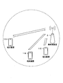
- FIG. 1 is a conceptual diagram of the wireless communication system of the present embodiment.
- the wireless communication system includes a terminal device 1 and a base station device 3.
- the terminal device 1 is set with one or a plurality of serving cells.
- a technique in which the terminal device 1 communicates via a plurality of serving cells is referred to as cell aggregation or carrier aggregation.
- carrier aggregation a plurality of set serving cells are also referred to as aggregated serving cells.
- TDD Time Division Duplex
- FDD Frequency Division Duplex
- TDD Time Division Duplex
- FDD Frequency Division Duplex
- a serving cell to which TDD is applied and a serving cell to which FDD is applied may be aggregated.
- a serving cell to which FDD is applied is also referred to as an FDD serving cell (FDD cell).
- FDD cell FDD serving cell
- a serving cell to which TDD is applied is also referred to as a TDD serving cell (TDD cell).
- TDD serving cell TDD serving cell
- LAA serving cell LAA serving cell
- FDD is applied in frame configuration type 1.
- TDD is applied in frame configuration type 2.
- the frame configuration type indicates the configuration of the radio frame.
- LAA (Licenced Assisted Access) is applied in the frame configuration type 3.
- Frame configuration type 3 (FS3) is applied to LAA operation (LAA secondary cell operation). Further, only normal CP may be applied to FS3.
- Ten subframes included in the radio frame are used for downlink transmission. Unless otherwise specified, or unless downlink transmission is detected in the subframe, the terminal apparatus 1 does not assume that any signal is present in a subframe, and processes the subframe as an empty subframe. .
- Downlink transmission occupies one or more consecutive subframes.
- the consecutive subframes may include a first subframe and a last subframe. That is, a continuous subframe may be composed of at least two subframes.
- a consecutive subframe includes more than one consecutive subframe in the time domain.
- the first subframe begins with any symbol or slot (eg, OFDM symbol # 0 or # 7) of that subframe.
- the last subframe is occupied by the full subframe (ie, 14 OFDM symbols) or the number of OFDM symbols indicated based on one of the DwPTS periods (ie, the number of symbols allocated for DwPTS).
- DwPTS is a period included in the special subframe. DwPTS may be used for switching between uplink transmission and downlink transmission.
- Whether or not a certain subframe is the last subframe among consecutive subframes is indicated to the terminal device 1 by a certain field (that is, DCI) included in the DCI format.
- the field may further indicate the number of OFDM symbols used in the subframe in which the field is detected or the next subframe.
- the base station apparatus 3 and the terminal apparatus 1 perform a predetermined channel access procedure before transmitting related downlink / uplink. That is, in the channel access procedure, when the transmission side determines that the channel used for transmission is clear (idle), the base station device 3 and / or the terminal device 1 on the transmission side can perform transmission. Also, in the channel access procedure, when the transmission side cannot determine that the channel used for transmission is clear (or when the channel is determined to be busy), the base station device 3 and / or the terminal device 1 on the transmission side Can not be done.
- the channel access procedure is also called LBT (ListenListbefore talk).
- the LAA secondary cell may be referred to as an LAA cell.
- Uplink transmission can occupy one or more consecutive subframes.
- the terminal device 1 that supports only downlink transmission in the LAA cell, and the terminal device 1 that supports downlink transmission and uplink transmission in the LAA cell transmit the capability information of the terminal device 1.
- the communication method supported by the own device may be notified.
- the terminal device 1 and the base station device 3 that support the FS3 may perform communication in a frequency band that does not require a license.
- the operating band that implements LAA using FS3 may be managed along with the EUTRA operating band table.
- the EUTRA operating band index may be managed from 1 to 44, and the operating band index corresponding to LAA (or LAA frequency) may be managed at 46.
- the index 46 only the downlink frequency band may be defined.
- an uplink frequency band may be reserved in advance as reserved or specified in the future.
- duplex mode corresponding to the operating band that performs LAA using FS3 is TDD.
- the physical channel may be transmitted based on at least a channel access procedure.
- the physical signal may be transmitted based on at least a channel access procedure.
- the set plurality of serving cells include one primary cell and one or more secondary cells.
- the primary cell is a serving cell in which an initial connection establishment (initial connection establishment) procedure is performed, a serving cell that has started an RRC connection reestablishment (Radio Resource Control connection re-establishment) procedure, or a cell designated as a primary cell in a handover procedure. It is.
- a secondary cell may be set when an RRC (Radio Resource Control) connection is established or later.
- a carrier corresponding to a serving cell is referred to as a downlink component carrier.
- a carrier corresponding to a serving cell is referred to as an uplink component carrier.
- the downlink component carrier and the uplink component carrier are collectively referred to as a component carrier.
- the terminal device 1 can simultaneously transmit a plurality of physical channels / a plurality of physical signals in a plurality of serving cells (component carriers) to be aggregated.
- the terminal device 1 can simultaneously receive a plurality of physical channels / a plurality of physical signals in a plurality of serving cells (component carriers) to be aggregated.
- MCG Master Cell Group
- SCG Secondary Cell Group
- the MCG may include one primary TAG and zero or more secondary TAGs.
- the SCG may include one primary TAG and zero or more secondary TAGs.
- TAG (Timing Advance Group) is a group of serving cells set by RRC (Radio Resource Control). The same timing advance value is applied to serving cells included in the same TAG. The timing advance is used to adjust the transmission timing of PUSCH / PUCCH / SRS / DMRS in the serving cell.
- the primary TAG of the MCG may include a primary cell and zero or more secondary cells.
- the SCG primary TAG may include a primary secondary cell and zero or more secondary cells.
- the secondary TAG may include one or more secondary cells.
- the secondary TAG does not include a primary cell and a primary secondary cell.
- FIG. 2 is a diagram illustrating a schematic configuration of a radio frame according to the present embodiment.
- the horizontal axis is a time axis.
- Each radio frame includes 10 subframes continuous in the time domain.
- Each subframe i includes two consecutive slots in the time domain. Two consecutive slots in the time domain, the slot of the slot number n s within a radio frame 2i, and the slot number n s within a radio frame is 2i + 1 slot.
- Each radio frame includes 10 subframes continuous in the time domain.
- the subframe is also referred to as TTI (Transmission
- FIG. 3 is a diagram illustrating a schematic configuration of the uplink slot according to the present embodiment.
- FIG. 3 shows the configuration of an uplink slot in one cell.
- the horizontal axis is a time axis
- the vertical axis is a frequency axis.
- l is an SC-FDMA (Single Carrier-Frequency Division Multiple Access) symbol number / index
- k is a subcarrier number / index.
- a physical signal or physical channel transmitted in each slot is represented by a resource grid.
- the resource grid is defined by a plurality of subcarriers and a plurality of SC-FDMA symbols.
- Each element in the resource grid is referred to as a resource element.
- a resource element is represented by a subcarrier number / index k and an SC-FDMA symbol number / index l.
- Resource grid is defined for each antenna port. In the present embodiment, description will be given for one antenna port. The present embodiment may be applied to each of a plurality of antenna ports.
- N UL symb indicates the number of SC-FDMA symbols included in one uplink slot.
- N UL symb is 7 for normal CP (normal cyclic prefix).
- N UL symb is 6 for extended CP (extended Cyclic Prefix).
- N UL RB is an uplink bandwidth setting for the serving cell, expressed as a multiple of N RB sc .
- N RB sc is a (physical) resource block size in the frequency domain expressed by the number of subcarriers.
- the subcarrier interval ⁇ f is 15 kHz
- N RB sc is 12 subcarriers. That is, in the present embodiment, N RB sc is 180 kHz.
- a resource block is used to represent a mapping of physical channels to resource elements.
- virtual resource blocks and physical resource blocks are defined.
- a physical channel is first mapped to a virtual resource block. Thereafter, the virtual resource block is mapped to the physical resource block.
- One physical resource block is defined by N UL symb consecutive SC-FDMA symbols in the time domain and N RB sc consecutive subcarriers in the frequency domain. Therefore, one physical resource block is composed of (N UL symb ⁇ N RB sc ) resource elements.
- One physical resource block corresponds to one slot in the time domain. Physical resource blocks are numbered (0, 1,..., N UL RB ⁇ 1) in order from the lowest frequency in the frequency domain.
- the downlink slot in this embodiment includes a plurality of OFDM symbols. Since the configuration of the downlink slot in the present embodiment is the same except that the resource grid is defined by a plurality of subcarriers and a plurality of OFDM symbols, description of the configuration of the downlink slot is omitted.
- the following uplink physical channels are used in uplink wireless communication from the terminal device 1 to the base station device 3.
- the uplink physical channel is used by the physical layer to transmit information output from the higher layer.
- -PUCCH Physical Uplink Control Channel
- PUSCH Physical Uplink Shared Channel
- PRACH Physical Random Access Channel
- Uplink Control Information includes downlink channel state information (Channel State Information: CSI) and a scheduling request (Scheduling Request: used to request PUSCH (Uplink-Shared Channel: UL-SCH) resources for initial transmission.
- CSI Downlink Channel State Information
- HARQ-ACK Hybrid, Automatic, Repeat, Request, ACKnowledgement
- HARQ-ACK indicates ACK (acknowledgement) or NACK (negative-acknowledgement).
- HARQ-ACK is also referred to as HARQ feedback, HARQ information, HARQ control information, and ACK / NACK.
- CSI includes a channel quality index (CQI: “Channel Quality Indicator”) and a rank index (RI: “Rank” Indicator).
- the channel quality indicator may further include a precoder matrix indicator (Precoder Matrix Indicator).
- CQI is an index related to channel quality (propagation strength)
- PMI is an index indicating the precoder.
- RI is an index that indicates a transmission rank.
- the PUSCH is used to transmit uplink data (Uplink-Shared Channel: UL-SCH).
- the PUSCH may be used to transmit HARQ-ACK and / or channel state information along with uplink data. Also, the PUSCH may be used to transmit only channel state information or only HARQ-ACK and channel state information.
- the PUSCH is used for transmitting the random access message 3.
- PRACH is used for transmitting a random access preamble (random access message 1).
- PRACH indicates the initial connection establishment (initial connection establishment) procedure, handover procedure, connection re-establishment (connection re-establishment) procedure, synchronization (timing adjustment) for uplink transmission, and PUSCH (UL-SCH) resource requirements. Used for.
- the random access preamble may be given by cyclically shifting the Zadoff-Chu sequence corresponding to the physical root sequence index u.
- the Zadoff-Chu sequence is generated based on the physical root sequence index u.
- a plurality of random access preambles may be defined.
- the random access preamble may be specified by an index of the random access preamble. Different random access preambles corresponding to different indexes of the random access preamble correspond to different combinations of physical root sequence index u and cyclic shift.
- the physical root sequence index u and the cyclic shift may be given based at least on information included in the system information.
- the Zadoff-Chu sequence x u (n) corresponding to the physical root sequence index u is given by the following equation (1).
- e is the number of Napiers.
- N ZC is the length of the Zadoff-Chu sequence x u (n).
- n is an integer that is incremented from 0 to N ZC ⁇ 1.
- the random access preamble (sequence of random access preambles) x u, v (n) is given by the following equation (2).
- Cv is a cyclic shift value.
- X mod Y is a function that outputs the remainder when X is divided by Y.
- Uplink physical signals are used in uplink wireless communication.
- Uplink physical signals are not used to transmit information output from higher layers, but are used by the physical layer.
- UL RS Uplink Reference Signal
- DMRS Demodulation Reference Signal
- SRS Sounding Reference Signal
- DMRS is related to transmission of PUSCH or PUCCH.
- DMRS is time-multiplexed with PUSCH or PUCCH.
- the base station apparatus 3 uses DMRS to perform propagation channel correction for PUSCH or PUCCH.
- transmitting both PUSCH and DMRS is simply referred to as transmitting PUSCH.
- transmitting both PUCCH and DMRS is simply referred to as transmitting PUCCH.
- SRS is not related to PUSCH or PUCCH transmission.
- the base station apparatus 3 may use SRS for measuring the channel state.
- the SRS is transmitted in the last SC-FDMA symbol of the subframe in the uplink subframe or the SC-FDMA symbol in UpPTS.
- the following downlink physical channels are used in downlink wireless communication from the base station apparatus 3 to the terminal apparatus 1.
- the downlink physical channel is used by the physical layer to transmit information output from the higher layer.
- PBCH Physical Broadcast Channel
- PCFICH Physical Control Format Indicator Channel
- PHICH Physical Hybrid automatic repeat request Indicator Channel
- PDCCH Physical Downlink Control Channel
- EPDCCH Enhanced Physical Downlink Control Channel
- PDSCH Physical Downlink Shared Channel
- PMCH Physical Multicast Channel
- the PBCH is used to broadcast a master information block (Master Information Block: MIB, Broadcast Channel: BCH) commonly used in the terminal device 1.
- SFN system frame number
- MIB is system information. For example, the MIB includes information indicating SFN.
- PCFICH is used for transmitting information indicating a region (OFDM symbol) used for transmission of PDCCH.
- PHICH is used to transmit a HARQ indicator for uplink data (Uplink Shared Channel: UL-SCH) received by the base station apparatus 3.
- the HARQ indicator indicates HARQ-ACK.
- the PDCCH and EPDCCH are used to transmit downlink control information (Downlink Control Information: DCI).
- DCI Downlink Control Information
- the downlink control information is also referred to as a DCI format.
- the downlink control information includes a downlink grant (downlink grant) and an uplink grant (uplink grant).
- the downlink grant is also referred to as downlink assignment (downlink allocation) or downlink assignment (downlink allocation).
- One downlink grant is used for scheduling one PDSCH in one serving cell.
- the downlink grant is used for scheduling the PDSCH in the same subframe as the subframe in which the downlink grant is transmitted.
- One uplink grant is used for scheduling one PUSCH in one serving cell.
- the uplink grant is used for scheduling PUSCH in a subframe that is four or more times after the subframe in which the uplink grant is transmitted.
- CRC parity bits added to the downlink grant or uplink grant include C-RNTI (Cell-Radio Network Temporary Identifier), Temporary C-RNTI, SPS (Semi Persistent Scheduling) C-RNTI, RA-RNTI (Random Access-Radio (Network-Temporary (Identifier)).
- C-RNTI and SPS C-RNTI are identifiers for identifying a terminal device in a cell.
- Temporary C-RNTI is used during contention-based random access procedures.
- RA-RNTI is used for scheduling of random access responses.
- the uplink grant to which the CRC parity bit scrambled by the RNTI is added is also referred to as an uplink grant for the RNTI and an uplink grant corresponding to the RNTI.
- a PDCCH including an uplink grant to which a CRC parity bit scrambled by RNTI is added is also referred to as a PDCCH for RNTI, a PDCCH corresponding to RNTI, a PDCCH addressed to RNTI, and a PDCCH including RNTI.
- the terminal device 1 may transmit the PUSCH including the transport block based on the detection of the PDCCH including the uplink grant to which the CRC parity bit scrambled by the C-RNTI is added.
- the retransmission of the transport block may be indicated by a PDCCH including an uplink grant to which a CRC parity bit scrambled by C-RNTI is added.
- SPS C-RNTI is used to periodically allocate PDSCH or PUSCH resources.
- the terminal device 1 detects the PDCCH including the uplink grant to which the CRC parity bit scrambled by the SPS C-RNTI is added and determines that the uplink grant is valid as the SPS activation command, the terminal device 1 Store the uplink grant as a configured uplink grant (configured uplink grant).
- the MAC layer of the terminal device 1 considers that the set uplink grant occurs periodically.
- the subframe in which the configured uplink grant is considered to be generated is given by the first period and the first offset.
- the terminal device 1 receives information indicating the first period from the base station device 3.
- Retransmission of transport blocks transmitted on the periodically allocated PUSCH is indicated by an uplink grant to which a CRC parity bit scrambled by the SPS C-RNTI is added.
- the set uplink grant is also referred to as an uplink grant set by MAC (Medium Access Control) or a first set uplink grant.
- PDSCH is used to transmit downlink data (Downlink Shared Channel: DL-SCH).
- the PDSCH is used to transmit a random access message 2 (random access response).
- the PDSCH is used for transmitting a handover command.
- the PDSCH is used to transmit system information including parameters used for initial access.
- PMCH is used to transmit multicast data (Multicast Channel: MCH).
- the downlink physical signal is not used to transmit information output from the upper layer, but is used by the physical layer.
- SS Synchronization signal
- DL RS Downlink Reference Signal
- the synchronization signal is used for the terminal device 1 to synchronize the downlink frequency domain and time domain.
- the synchronization signal includes PSS (Primary Synchronization Signal) and SSS (Second Synchronization Signal).
- the downlink reference signal is used for the terminal device 1 to correct the propagation path of the downlink physical channel.
- the downlink reference signal is used for the terminal device 1 to calculate downlink channel state information.
- the following seven types of downlink reference signals are used.
- -CRS Cell-specific Reference Signal
- URS UE-specific Reference Signal
- PDSCH PDSCH
- DMRS Demodulation Reference Signal
- EPDCCH Non-Zero Power Chanel State Information-Reference Signal
- ZP CSI-RS Zero Power Chanel State Information-Reference Signal
- MBSFN RS Multimedia Broadcast and Multicast Service over Single Frequency Network Reference signal
- PRS Positioning Reference Signal
- the downlink physical channel and the downlink physical signal are collectively referred to as a downlink signal.
- the uplink physical channel and the uplink physical signal are collectively referred to as an uplink signal.
- the downlink physical channel and the uplink physical channel are collectively referred to as a physical channel.
- the downlink physical signal and the uplink physical signal are collectively referred to as a physical signal.
- BCH, MCH, UL-SCH and DL-SCH are transport channels.
- a channel used in a medium access control (Medium Access Control: MAC) layer is referred to as a transport channel.
- a transport channel unit used in the MAC layer is also referred to as a transport block (transport block: TB) or a MAC PDU (Protocol Data Unit).
- HARQ HybridbrAutomatic Repeat reQuest
- the transport block is a unit of data that the MAC layer delivers to the physical layer.
- the transport block is mapped to a code word, and an encoding process is performed for each code word.
- the base station device 3 and the terminal device 1 exchange (transmit / receive) signals in a higher layer.
- the base station device 3 and the terminal device 1 transmit and receive RRC signaling (RRC message: Radio Resource Control message, RRC information: also called Radio Resource Control information) in a radio resource control (RRC: Radio Resource Control) layer. May be.
- RRC signaling RRC message: Radio Resource Control message, RRC information: also called Radio Resource Control information
- RRC Radio Resource Control
- the base station device 3 and the terminal device 1 may transmit and receive MAC CE (Control Element) in a medium access control (MAC: Medium Access Control) layer.
- MAC Medium Access Control
- RRC signaling and / or MAC CE is also referred to as higher layer signaling.
- the PUSCH and PDSCH are used to transmit RRC signaling and MAC CE.
- the RRC signaling transmitted by the PDSCH from the base station apparatus 3 may be common signaling for a plurality of terminal apparatuses 1 in the cell.
- the RRC signaling transmitted from the base station device 3 on the PDSCH may be dedicated signaling for a certain terminal device 1 (also referred to as dedicated signaling or UE specific signaling).
- the cell specific parameter may be transmitted using common signaling for a plurality of terminal devices 1 in a cell or dedicated signaling for a certain terminal device 1.
- the UE specific parameter may be transmitted to a certain terminal device 1 using dedicated signaling.
- FIG. 4 is a schematic block diagram showing the configuration of the terminal device 1 of the present embodiment.
- the terminal device 1 includes an upper layer processing unit 101, a control unit 103, a receiving unit 105, a transmitting unit 107, and a transmission / reception antenna 109.
- the upper layer processing unit 101 includes a radio resource control unit 1011 and a scheduling unit 1013.
- the reception unit 105 includes a decoding unit 1051, a demodulation unit 1053, a demultiplexing unit 1055, a radio reception unit 1057, and a channel measurement unit 1059.
- the transmission unit 107 includes an encoding unit 1071, a PUSCH generation unit 1073, a PUCCH generation unit 1075, a multiplexing unit 1077, a radio transmission unit 1079, and an uplink reference signal generation unit 10711.
- the upper layer processing unit 101 outputs uplink data generated by a user operation or the like to the transmission unit 107.
- the upper layer processing unit 101 includes a medium access control (MAC: Medium Access Control) layer, a packet data integration protocol (Packet Data Convergence Protocol: PDCP) layer, a radio link control (Radio Link Control: RLC) layer, and radio resource control. Process the (Radio Resource Control: RRC) layer. Further, upper layer processing section 101 generates control information for controlling receiving section 105 and transmitting section 107 based on downlink control information received by PDCCH, and outputs the control information to control section 103.
- MAC Medium Access Control
- PDCP Packet Data Convergence Protocol
- RLC Radio Link Control
- RRC Radio Resource Control
- the radio resource control unit 1011 included in the upper layer processing unit 101 manages various setting information of the own device. For example, the radio resource control unit 1011 manages the set serving cell. Also, the radio resource control unit 1011 generates information arranged in each uplink channel and outputs the information to the transmission unit 107.
- the scheduling unit 1013 included in the higher layer processing unit 101 stores the downlink control information received via the receiving unit 105.
- the scheduling unit 1013 controls the transmission unit 107 via the control unit 103 so as to transmit the PUSCH according to the received uplink grant in the subframe that is four or three after the subframe that has received the uplink grant. To do.
- the scheduling unit 1013 controls the reception unit 105 via the control unit 103 so as to receive the PDSCH according to the received downlink grant in the subframe that has received the downlink grant.
- the control unit 103 generates a control signal for controlling the receiving unit 105 and the transmitting unit 107 based on the control information from the higher layer processing unit 101. Control unit 103 outputs the generated control signal to receiving unit 105 and transmitting unit 107 to control receiving unit 105 and transmitting unit 107.
- the receiving unit 105 separates, demodulates, and decodes the received signal received from the base station apparatus 3 via the transmission / reception antenna 109 according to the control signal input from the control unit 103, and sends the decoded information to the upper layer processing unit 101. Output.
- the radio reception unit 1057 performs orthogonal demodulation on the downlink signal received via the transmission / reception antenna 109, and converts the orthogonally demodulated analog signal into a digital signal.
- the wireless reception unit 1057 performs fast Fourier transform (FFT) on the digital signal to extract a frequency domain signal.
- Radio receiving section 1057 outputs a frequency domain signal to demultiplexing section 1055.
- the signal in the frequency domain is expressed as a complex value symbol corresponding to the subcarrier index k and the symbol index l.
- the demultiplexing unit 1055 demultiplexes the frequency domain signal input from the radio receiving unit 1057 into a PDCCH, a PDSCH, and a downlink reference signal.
- the demultiplexing unit 1055 outputs the separated downlink reference signal to the channel measuring unit 1059. Further, demultiplexing section 1055 outputs the separated PDCCH and PDSCH to demodulation section 1053.
- Demodulation section 1053 demodulates PDCCH and PDSCH with respect to modulation schemes such as QPSK, 16QAM (Quadrature Amplitude Modulation), 64QAM, and outputs the result to decoding section 1051.
- modulation schemes such as QPSK, 16QAM (Quadrature Amplitude Modulation), 64QAM, and outputs the result to decoding section 1051.
- the decoding unit 1051 decodes the downlink data and outputs the decoded downlink data to the higher layer processing unit 101.
- Channel measurement section 1059 calculates an estimated value of the downlink propagation path from the downlink reference signal, and outputs the estimated value to demultiplexing section 1055.
- the channel measurement unit 1059 calculates channel state information and outputs the channel state information to the upper layer processing unit 101.
- the transmission unit 107 generates an uplink reference signal according to the control signal input from the control unit 103, encodes and modulates uplink data and uplink control information input from the higher layer processing unit 101, and PUCCH,
- the PUSCH and the uplink reference signal are multiplexed and transmitted to the base station apparatus 3 via the transmission / reception antenna 109.
- the number of OFDM symbols used for PUSCH transmission may be given based on at least a random access procedure. Also, the number of OFDM symbols used for PUSCH transmission may be given based at least on the type / form of random access procedure to which the PUSCH transmission corresponds. Further, the number of OFDM symbols used for PUSCH transmission may be given based on at least the format of the random access preamble. Further, the number of OFDM symbols used for PUSCH transmission may be given for each format of the random access preamble. Further, the number of OFDM symbols used for PUSCH transmission may be given based at least on higher layer signals. The type / form of the random access procedure will be described later.
- the encoding unit 1071 encodes the uplink control information and the uplink data input from the higher layer processing unit 101, and outputs the encoded bits to the PUSCH generation unit 1073 and / or the PUCCH generation unit 1075.
- the encoding unit 1071 encodes uplink data and generates an encoded bit sequence. Also, encoding section 1071 calculates SC-FDMA symbol count N PUSCH-initial symb for PUSCH initial transmission.
- PUSCH initial transmission refers to PUSCH used for initial transmission of a transport block including a coded bit sequence. Also, the encoding unit 1071 generates a first sequence by interleaving (order changing, rearranging, rearranging) the encoded bit sequence based at least on the SC-FDMA symbol number N PUSCH-initial symb . The first sequence is input to the PUSCH generation unit 1073.
- a method of calculating the number of SC-FDMA symbols N PUSCH-initial symb for initial PUSCH transmission will be described later.
- the interleaving of the encoded bit sequence may be a rearrangement of the encoded bit sequence.
- the rearrangement of the coded bit sequence may be given based on at least the number of SC-FDMA symbols for PUSCH initial transmission.
- a matrix may be used for interleaving the coded bit sequence.
- the matrix columns correspond to SC-FDMA symbols.
- One element of the matrix corresponds to one coded modulation symbol.
- a coded modulation symbol is a group of X coded bits.
- X is the modulation order (modulation order Q m ) for the transport block (uplink data).
- One complex-valued symbol is generated from one coded modulation symbol.
- FIG. 5 is a diagram illustrating an example of interleaving of encoded bit sequences by the encoding unit 1071 of the present embodiment.
- the vertical axis (or matrix row) is an axis corresponding to the number of subcarriers.
- H 1 is the number of coded modulation symbols in the first sequence.
- H 1 may be given by the sum of the number of coded modulation symbols in the first sequence and the number of coded modulation symbols for the coded bit sequence of CQI.
- mapping may be writing (Write).
- sequence mapped for each group of X encoded bits is output in the direction indicated by the dotted line (in units of columns) to generate the first sequence.
- outputting may be reading (Read).
- one complex value symbol is obtained by modulating an encoded modulation symbol formed by a group of X encoded bits arranged in each element of FIG. 5 based on a predetermined modulation scheme. Is generated.
- a plurality of complex-valued symbols corresponding to each column in FIG. 5 are subjected to discrete Fourier transform (Transform Precoding), and a second sequence is generated. The second series is output to multiplexing section 1077.
- the PUCCH generation unit 1075 generates a PUCCH signal based on the encoded bits of the uplink control information (HARQ-ACK, CQI, RI, etc.) input from the encoding unit 1071, and multiplexes the generated PUCCH signal Output to the unit 1077.
- HARQ-ACK uplink control information
- CQI CQI
- RI RI
- the uplink reference signal generation unit 10711 generates an uplink reference signal and outputs the generated uplink reference signal to the multiplexing unit 1077.
- the multiplexing unit 1077 is a signal input from the PUSCH generation unit 1073 and / or a signal input from the PUCCH generation unit 1075 and / or an uplink reference signal generation unit according to the control signal input from the control unit 103.
- the uplink reference signal input from 10711 is multiplexed to the uplink resource element for each transmission antenna port.
- the multiplexing unit 1077 inputs the multiplexed signal to the wireless transmission unit 1079.
- FIG. 6 is a diagram illustrating an example of the second series resource mapping input from the PUSCH generation unit 1073 by the multiplexing unit 1077 according to the present embodiment.
- the vertical axis represents frequency (subcarrier index k) and the horizontal axis represents time (symbol index l).
- the second series is mapped to each resource element in units of columns, as indicated by dotted arrows. That is, the second sequence is mapped to the resource element in the frequency direction (Frequency first mapping).
- the resource element to which the second sequence is mapped is a resource element included in at least a resource block allocated for PUSCH transmission.
- the second sequence may be included in a resource block allocated for PUSCH transmission and may not be mapped to a resource element that satisfies a predetermined condition.
- the second sequence when DMRS is mapped to resource elements indicated by diagonal lines, the second sequence is not mapped to resource elements indicated by diagonal lines.
- the SRS when the SRS is mapped to the resource element indicated by the grid line, the second series is not mapped to the resource element indicated by the grid line.
- the wireless transmission unit 1079 generates a baseband digital signal by performing inverse fast Fourier transform (Inverse Fastier Transform: IFFT) on the multiplexed signal, converts the baseband digital signal into an analog signal, and converts the analog signal from the analog signal. Generates in-phase and quadrature components of intermediate frequency, removes extra frequency component for intermediate frequency band, converts intermediate frequency signal to high frequency signal (up-convert: up convert), removes extra frequency component The power is amplified and output to the transmission / reception antenna 109 for transmission.
- IFFT inverse fast Fourier transform
- FIG. 7 is a schematic block diagram showing the configuration of the base station apparatus 3 of the present embodiment.
- the base station apparatus 3 includes an upper layer processing unit 301, a control unit 303, a reception unit 305, a transmission unit 307, and a transmission / reception antenna 309.
- the upper layer processing unit 301 includes a radio resource control unit 3011 and a scheduling unit 3013.
- the reception unit 305 includes a data demodulation / decoding unit 3051, a control information demodulation / decoding unit 3053, a demultiplexing unit 3055, a wireless reception unit 3057, and a channel measurement unit 3059.
- the transmission unit 307 includes an encoding unit 3071, a modulation unit 3073, a multiplexing unit 3075, a radio transmission unit 3077, and a downlink reference signal generation unit 3079.
- the upper layer processing unit 301 includes a medium access control (MAC: Medium Access Control) layer, a packet data integration protocol (Packet Data Convergence Protocol: PDCP) layer, a radio link control (Radio Link Control: RLC) layer, a radio resource control (Radio). Resource (Control: RRC) layer processing. Further, upper layer processing section 301 generates control information for controlling receiving section 305 and transmitting section 307 and outputs the control information to control section 303.
- MAC Medium Access Control
- PDCP Packet Data Convergence Protocol
- RLC Radio Link Control
- Radio Radio Resource
- the radio resource control unit 3011 included in the higher layer processing unit 301 generates downlink data, RRC signal, and MAC CE (Control Element) arranged in the PDSCH, or acquires them from the upper node and outputs them to the scheduling unit 3013. Further, the radio resource control unit 3011 manages various setting information of each terminal device 1. For example, the radio resource control unit 3011 performs management of the serving cell set in the terminal device 1 and the like.
- the scheduling unit 3013 included in the higher layer processing unit 301 manages PUSCH and PUCCH radio resources allocated to the terminal device 1.
- the scheduling unit 3013 When the PUSCH radio resource is allocated to the terminal device 1, the scheduling unit 3013 generates an uplink grant indicating the allocation of the PUSCH radio resource, and outputs the generated uplink grant to the transmission unit 307.
- the control unit 303 generates a control signal for controlling the reception unit 305 and the transmission unit 307 based on the control information from the higher layer processing unit 301.
- the control unit 303 outputs the generated control signal to the reception unit 305 and the transmission unit 307 and controls the reception unit 305 and the transmission unit 307.
- the receiving unit 305 separates, demodulates and decodes the received signal received from the terminal device 1 via the transmission / reception antenna 309 according to the control signal input from the control unit 303, and outputs the decoded information to the higher layer processing unit 301. .
- the radio reception unit 3057 orthogonally demodulates the uplink signal received via the transmission / reception antenna 309, and converts the orthogonally demodulated analog signal into a digital signal.
- the radio reception unit 3057 performs fast Fourier transform (FFT) on the digital signal, extracts a frequency domain signal, and outputs the signal to the demultiplexing unit 3055.
- FFT fast Fourier transform
- the demultiplexing unit 3055 demultiplexes the signal input from the radio receiving unit 3057 into signals such as PUCCH, PUSCH, and uplink reference signal. Note that this separation is performed based on radio resource allocation information included in the uplink grant that is determined in advance by the radio resource control unit 3011 by the base station device 3 and notified to each terminal device 1.
- the demultiplexing unit 3055 compensates for the propagation paths of the PUCCH / sPUCCH and the PUSCH / sPUSCH based on the propagation path estimation value input from the channel measurement unit 3059. Further, the demultiplexing unit 3055 outputs the separated uplink reference signal to the channel measurement unit 3059.
- demultiplexing unit 3055 demultiplexing the signal input from radio receiving unit 3057 into signals such as PUCCH, PUSCH, and uplink reference signal corresponds to the resource mapping method of multiplexing unit 1077 included in terminal apparatus 1. Description is omitted.
- the demultiplexing unit 3055 acquires the complex value symbol of the uplink data and the complex value symbol of the uplink control information from the separated PUCCH and PUSCH signals.
- the demultiplexing unit 3055 outputs the complex value symbol of the uplink data acquired from the PUSCH signal to the data demodulation / decoding unit 3051.
- the demultiplexing unit 3055 outputs the PUCCH signal or the complex value symbol of the uplink control information acquired from the PUSCH signal to the control information demodulation / decoding unit 3053.
- the channel measurement unit 3059 measures an estimated value of the propagation path, channel quality, and the like from the uplink reference signal input from the demultiplexing unit 3055, and outputs it to the demultiplexing unit 3055 and the upper layer processing unit 301.
- the data demodulation / decoding unit 3051 decodes the uplink data from the complex value symbol of the uplink data input from the demultiplexing unit 3055.
- the data demodulation / decoding unit 3051 outputs the decoded uplink data to the higher layer processing unit 301.
- the method of decoding uplink data from the complex value symbol of the uplink data input from the demultiplexing unit 3055 by the data demodulating / decoding unit 3051 corresponds to the operation of the encoding unit 1071 included in the terminal device 1, and therefore will be described. Omitted.
- the control information demodulation / decoding unit 3053 decodes the uplink control information from the complex value symbols of the uplink control information input from the demultiplexing unit 3055.
- the control information demodulation / decoding unit 3053 outputs the decoded uplink control information to the higher layer processing unit 301.
- the transmission unit 307 generates a downlink reference signal according to the control signal input from the control unit 303, encodes and modulates the downlink control information and downlink data input from the higher layer processing unit 301, and performs PDCCH , The PDSCH, and the downlink reference signal are multiplexed, and the signal is transmitted to the terminal device 1 via the transmission / reception antenna 309.
- the encoding unit 3071 encodes downlink control information and downlink data input from the higher layer processing unit 301.
- the modulation unit 3073 modulates the coded bits input from the coding unit 3071 using a modulation scheme such as QPSK, 16QAM, or 64QAM.
- the downlink reference signal generation unit 3079 generates a downlink reference signal.
- Multiplexer 3075 multiplexes the modulation symbols and downlink reference signals for each channel.
- Radio transmission section 3077 performs inverse fast Fourier transform (Inverse Fastier Transform: IFFT) on the modulated modulation symbols and the like to perform OFDM modulation, generate a baseband digital signal, and convert the baseband digital signal to Converts to an analog signal, generates in-phase and quadrature components of the intermediate frequency from the analog signal, removes excess frequency components for the intermediate frequency band, and converts the intermediate frequency signal to a high-frequency signal (up-convert: upconvert) Then, excess frequency components are removed, power amplification is performed, and output to the transmission / reception antenna 309 is transmitted.
- IFFT inverse fast Fourier transform
- the random access procedure includes a contention-based random access procedure (contention-based access procedure) and a non-contention basednonrandom access procedure.
- the contention-based random access procedure includes a two-step contention-based random access procedure (2 step contention based random access procedure) and a four-step contention-based random access procedure (4 step contention based random access procedure). That is, the type / form of random access procedure may include a two-step contention base, a four-step contention base, and a non-contention base.
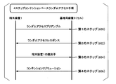
- FIG. 8 is a diagram showing an example of a 4-step contention-based random access procedure in the present embodiment.
- the four-step contention-based random access procedure includes a first step (600), a second step (602), a third step (604), and a fourth step (606).
- the terminal device 1 transmits a random access preamble.
- the random access preamble is included in the PRACH.
- the MAC layer itself of the terminal device 1 selects an index of the random access preamble. That is, in the first step (600), the base station device 3 does not notify the terminal device 1 of the index of the random access preamble.
- the terminal device 1 receives a random access response.
- the random access response is included in the PDSCH.
- PDCCH for RA-RNTI is used for scheduling of PDSCH including a random access response.
- the value of RA-RNTI may be given based on the PRACH resources used for transmission of the random access preamble in the first step (600).
- the random access response includes a random access preamble identifier indicating an index of a random access preamble, information indicating an uplink grant, Temporary C-RNTI, and information indicating a timing advance.
- the terminal device 1 considers that the random access response has been successfully received.
- the terminal device 1 transmits the identifier of the terminal device 1.
- the identifier of the terminal device 1 may be C-RNTI.
- the identifier of the terminal device 1 or C-RNTI is included in the PUSCH.
- the identifier of the terminal device 1 or the PUSCH for C-RNTI is scheduled by the uplink grant included in the random access response.
- the terminal device 1 receives the contention resolution.
- the contention resolution may be a UE contention resolution identifier or C-RNTI.
- the terminal device 1 transmits C-RNTI in the PUSCH of the third step (604) and the terminal device 1 receives the PDCCH for C-RNTI, the terminal device 1 succeeds in contention resolution. It may be considered that the random access procedure has been successfully completed.
- Information indicating the UE contention resolution identifier is included in the PDSCH.
- PDCCH for Temporary C-RNTI is used for scheduling of the PDSCH.
- the terminal device 1 has not transmitted C-RNTI in the PUSCH of the third step (604), and (ii) the terminal device 1 is the identifier of the terminal device 1 in the PUSCH of the third step (604) And (iii) the terminal device 1 receives the PDCCH for the Temporary C-RNTI, and (iv) the PDSCH scheduled by the PDCCH includes information indicating the UE contention resolution identifier. And (v) if the UE contention resolution identifier matches the identifier of the terminal device 1 transmitted in the third step (604), the terminal device 1 has succeeded in contention resolution. May be considered and the random access procedure has been successfully completed. It may be.
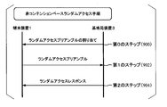
- FIG. 9 is a diagram showing an example of a two-step contention-based random access procedure in the present embodiment.
- the two-step contention based random access procedure includes a first step (700) and a second step (702).
- the random access preamble and the identifier of the terminal device 1 are transmitted.
- the identifier of the terminal device 1 may be C-RNTI.
- the random access preamble may be included in the PRACH.
- the identifier of the terminal device 1 may be included in the PUSCH.
- the random access preamble and the identifier of the terminal device 1 may be included in the same physical channel.
- the MAC layer itself of the terminal device 1 selects an index of the random access preamble. That is, in the first step (700), the base station apparatus 3 does not notify the terminal apparatus 1 of the index of the random access preamble.
- the added channel is also referred to as a PUSCH. That is, the PUSCH may be a channel other than the PRACH used at least for transmitting the identifier of the terminal device 1 in the first step (700).
- the added channel is also referred to as PUSCH. That is, in the two-step contention-based random access procedure, the PUSCH may be a channel other than the PRACH that is used at least for transmitting the identifier of the terminal device 1.
- the terminal device 1 receives the contention resolution.
- the contention resolution may be a UE contention resolution identifier or C-RNTI.
- the terminal device 1 has transmitted C-RNTI in the first step (700) and the terminal device 1 has received a PDCCH including the C-RNTI, the terminal device 1 has succeeded in contention resolution. And the random access procedure may have been successfully completed.
- the UE contention resolution identifier is included in the PDSCH.
- a DCI format to which a CRC scrambled by X-RNTI is added may be used.
- the X-RNTI is a resource (PRACH resource) used for transmission of a random access preamble and / or a resource (PUSCH resource) used for transmission of an identifier of the terminal device 1 in the first step (700). Resource).
- X-RNTI may be RA-RNTI.
- the terminal device 1 has not transmitted C-RNTI in the first step (700), and (ii) the terminal device 1 has transmitted the identifier of the terminal device 1 in the first step (700).
- the terminal device 1 receives the PDCCH for the X-RNTI, and (iv) the PDSCH scheduled by the PDCCH includes information indicating the UE contention resolution identifier, and ( v) If the UE contention resolution identifier matches the identifier of the terminal device 1 transmitted in the first step (700), the terminal device 1 may be regarded as having succeeded in contention resolution, And it may be considered that the random access procedure has been successfully completed.
- the PDSCH scheduled by the PDCCH for X-RNTI may include some or all of the uplink grant, information indicating C-RNTI, and information indicating timing advance.
- the PDSCH scheduled by the PDCCH for X-RNTI may not include information indicating the index of the random access preamble.
- the terminal device 1 may set C-RNTI to a value of information indicating C-RNTI.
- FIG. 10 is a diagram showing a modification of the two-step contention-based random access procedure in the present embodiment.
- a variation of the two-step contention based random access procedure includes a first step (800), a second step (802), a third step (804), and a fourth step (806).
- the first step (800) is the same as the first step (700).
- the second step (802) is the same as the second step (602).
- the third step (804) is the same as the third step (604).
- the fourth step (806) is the same as the fourth step (606). That is, after the first step of the two-step random access procedure, the two-step contention-based random access procedure may be shifted to the four-step contention-based random access procedure.
- the base station apparatus 3 detects the random access response in the second step (802). Send. That is, in the first step of the two-step random access procedure, when the base station device 3 detects the random access preamble and cannot detect the identifier of the terminal device 1, the base station device 3 performs the four-step random access procedure.
- the second step may be started.
- the base station device 3 detects the random access preamble and the identifier of the terminal device 1 in the first step of the two-step random access procedure, the base station device 3 starts the second step of the two-step random access procedure. May be.
- the terminal device 1 After the first step (700, 800) of the two-step contention-based random access procedure, the terminal device 1 performs the contention resolution of the second step (702) and the second step (802).
- the random access response may be monitored. That is, in the second step (702, 802), the terminal device 1 may monitor the PDCCH related to the random access response and the PDCCH related to the contention resolution.
- the PDCCH related to the random access response may be a PDCCH for RA-RNTI.
- the PDCCH associated with contention resolution may be a PDCCH for X-RNTI.
- the terminal device 1 may monitor the random access response of the second step (602) after the first step (600) of the four-step contention-based random access procedure. That is, in the second step (602), the terminal device 1 may monitor the PDCCH related to the random access response. In the second step (602), the terminal device 1 may not monitor contention resolution. That is, in the second step (602), the terminal device 1 does not have to monitor the PDCCH related to contention resolution.
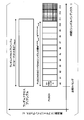
- FIG. 11 is a diagram showing an example of a non-contention based random access procedure in the present embodiment.
- the non-contention based random access procedure includes a zero step (900), a first step (902), and a second step (904).
- the terminal device 1 receives the assignment of the random access preamble.
- Random access preamble assignment may be included in a handover command or PDCCH for C-RNTI.
- the assignment of the random access preamble may indicate an index of the random access preamble.
- the PDCCH including the allocation of the random access preamble is also referred to as a PDCCH order or a PDCCH order that instructs the start of the random access procedure.
- the terminal device 1 selects a random access preamble based on the allocation of the random access preamble and transmits the selected random access preamble.
- the random access preamble is included in the PRACH.
- the MAC layer itself of the terminal device 1 does not select the index of the random access preamble.
- the terminal device 1 receives a random access response.
- the random access response is included in the PDSCH.
- PDCCH for RA-RNTI is used for scheduling of PDSCH including a random access response.
- the value of RA-RNTI may be given based on the PRACH resources used for transmission of the random access preamble in the first step (900).
- the random access response includes a random access preamble identifier indicating an index of a random access preamble, information indicating an uplink grant, Temporary C-RNTI, and information indicating a timing advance. If the random access response includes a random access preamble identifier corresponding to the random access preamble transmitted in the first step (900), it is considered that the random access response has been successfully received.
- the terminal device 1 includes a random access response including a random access preamble identifier corresponding to the random access preamble transmitted in the first step (900), and the allocation of the random access preamble is notified, and When the MAC of the terminal device 1 has not selected the random access preamble index, the terminal device 1 considers that the random access procedure has been completed successfully.
- the terminal device 1 may start the 4-step contention-based random access procedure. That is, when the MAC of the terminal device 1 does not select the random access preamble index, the random access preamble assignment may not be the first predetermined value.
- the terminal device 1 may start the 2-step contention-based random access procedure. That is, when the MAC of the terminal device 1 does not select the random access preamble index, the random access preamble allocation is different from both the first predetermined value and the second predetermined value. May be.
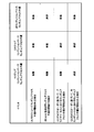
- FIG. 12 is a diagram showing an example of correspondence between an event and a random access procedure in this embodiment.
- the random access procedure consists of (event i) initial access from RRC_IDLE, (event ii) RRC connection re-establishment, (event iii) handover, (event iv) downlink data arrival during RRC_CONNECTED, (event v) during RRC_CONNECTED For uplink data arrival and (event vi) time adjustment for secondary TAG.
- the random access procedure for downlink data arrival during RRC_CONNECTED may be performed when the uplink synchronization status is asynchronous.
- the random access procedure for uplink data arrival during RRC_CONNECTED may be performed when the uplink synchronization status is asynchronous or there is no PUCCH resource for scheduling request.
- the random access procedure regarding event i to event v may be executed in the primary cell.
- the first step in the random access procedure for event vi may be performed in the secondary cell. That is, (event vi)
- the random access procedure executed for time adjustment for the secondary TAG is started in the secondary cell belonging to the secondary TAG.
- the random access procedure for initial access from RRC_IDLE may include a 4-step contention-based random access procedure and a 2-step contention-based random access procedure.
- the random access procedure for initial access from RRC_IDLE may not include a non-contention based random access procedure.
- a random access procedure for initial access from RRC_IDLE may be initiated by RRC.
- the random access procedure for re-establishing the RRC connection may include a 4-step contention-based random access procedure and a 2-step contention-based random access procedure.
- the random access procedure for re-establishing the RRC connection may not include a non-contention based random access procedure.
- the random access procedure for re-establishing the RRC connection may be initiated by the RRC.
- the fact that the random access procedure includes a four-step contention-based random access procedure means that the four-step contention-based random access procedure is supported, that the four-step contention-based random access procedure is valid, or that the four-step contention-based random access procedure is valid. It may be that a tension-based random access procedure is applicable. The same applies to the two-step contention-based random access procedure and the non-contention-based random access procedure.
- the system information transmitted / notified by the base station device 3 may include PRACH information and random access information.
- PRACH information information indicating the resource of PRACH, information about the physical root sequence index u about random access preamble, and may contain information about the cyclic shift C v for the random access preamble.
- the physical root sequence index u and the cyclic shift Cv are used to determine a sequence of random access preambles.
- the random access information may include information indicating the number of random access preambles and information indicating the number of random access preambles for the contention-based random access procedure.
- the system information may also include information for a two-step contention based random access procedure.
- the information for the two-step contention-based random access procedure is information indicating that the two-step contention-based random access procedure is supported in the cell, and the terminal device in the first step of the two-step contention-based random access procedure Information indicating a resource for transmitting one identifier, information indicating a modulation scheme of data including the identifier of the terminal device 1 in the first step of the two-step contention-based random access procedure, and / or RSRP (Reference Signal Information indicating a threshold of (Received Power) may be included.
- the system information does not include allocation of a random access preamble for the 0th step of the non-contention based random access procedure.
- the terminal device 1 measures RSRP from the downlink reference signal of the cell.
- the terminal device 1 may start one of the 2-step contention-based random access procedure and the 4-step contention-based random access procedure based on the measured RSRP and the RSRP threshold value. If the measured RSRP does not exceed the RSRP threshold, the terminal device 1 may start a 4-step contention-based random access procedure.
- the terminal device 1 may start a two-step contention-based random access procedure when the measured RSRP exceeds the RSRP threshold.
- the random access procedure for handover may include a 4-step contention-based random access procedure, a 2-step contention-based random access procedure, and a non-contention-based random access procedure.
- the handover command includes the above-described PRACH information, the above-described random access information, the information for the above-described two-step contention-based random access procedure, and / or the random for the zeroth step of the non-contention-based random access procedure. Access preamble assignment may also be included.
- the terminal device 1 starts any one of the 4-step contention-based random access procedure, the 2-step contention-based random access procedure, and the non-contention-based random access procedure based on the information included in the handover command. May be.
- the terminal device 1 may start a non-contention based random access procedure when the handover command includes assignment of a random access preamble.
- the terminal device 1 is based on the measured RSRP and the RSRP threshold value. Thus, one of the two-step contention-based random access procedure and the four-step contention-based random access procedure may be started.
- the terminal device 1 is based on the measured RSRP and the RSRP threshold value. Thus, one of the two-step contention-based random access procedure and the four-step contention-based random access procedure may be started.
- the terminal device 1 may start a 4-step contention-based random access procedure when the measured RSRP does not exceed the RSRP threshold.
- the terminal device 1 may start a two-step contention-based random access procedure when the measured RSRP exceeds the RSRP threshold.
- the terminal device 1 may start the 4-step contention-based random access procedure when the handover command includes random access preamble assignment and the random access preamble assignment indicates the first predetermined value.
- the terminal apparatus 1 includes a random access preamble assignment in the handover command, the random access preamble assignment indicates a second predetermined value, and the handover command includes a two-step contention-based random access procedure. If information is included, a two-step contention based random access procedure may be initiated.
- the terminal device 1 starts a 4-step contention-based random access procedure when the handover command does not include the assignment of the random access preamble and the handover command does not include information for the 2-step contention-based random access procedure. May be.
- the random access procedure for downlink data arrival during RRC_CONNECTED may include a 4-step contention-based random access procedure and a non-contention-based random access procedure.
- the random access procedure for downlink data arrival during RRC_CONNECTED may not include a two-step contention based random access procedure.
- the random access procedure for downlink data arrival during RRC_CONNECTED is initiated by the PDCCH order.
- the terminal device 1 may start the non-contention based random access procedure.
- the terminal device 1 may start a 4-step contention-based random access procedure. Even if the allocation of the random access preamble included in the PDCCH order is the second predetermined value, the terminal device 1 may start the 4-step contention-based random access procedure.
- the random access procedure for uplink data arrival during RRC_CONNECTED may include a 4-step contention-based random access procedure and a 2-step contention-based random access procedure.
- the random access procedure for uplink data arrival during RRC_CONNECTED may not include a non-contention based random access procedure.
- the random access procedure for uplink data arrival during RRC_CONNECTED is initiated by the MAC itself.
- Event vi The random access procedure performed for time adjustment for the secondary TAG is initiated by the PDCCH order. That is, the allocation of the random access preamble included in the PDCCH order instructing the start of the random access procedure in the secondary cell indicates a value other than the first predetermined value.
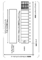
- FIG. 13 is a diagram showing another example of the correspondence between the event and the random access procedure in this embodiment.
- the random access procedure is initiated by (Event A) RRC, (Event B) MAC itself, or (Event C) PDCCH order.
- Random access procedures initiated by RRC may include 4-step contention-based random access procedures, 2-step contention-based random access procedures, and non-contention-based random access procedures.
- Event B The random access procedure initiated by the MAC itself may include a 4-step contention-based random access procedure and a 2-step contention-based random access procedure.
- Event B The random access procedure initiated by the MAC itself may not include a non-contention based random access procedure.
- the random access procedure initiated by the PDCCH order may include a 4-step contention-based random access procedure and a non-contention-based random access procedure.
- the random access procedure initiated by the PDCCH order may not include a two-step contention based random access procedure.
- the random access procedure started in the primary cell based on the PDCCH order may include a 4-step contention-based random access procedure and a non-contention-based random access procedure.
- the random access procedure initiated in the primary cell based on the PDCCH order may not include a two-step contention based random access procedure.
- the random access procedure initiated in the secondary cell based on the PDCCH order may include a non-contention based random access procedure.
- the random access procedure started in the secondary cell based on the PDCCH order may not include the 4-step contention-based random access procedure and the 2-step contention-based random access procedure.
- the SC-FDMA symbol number N PUSCH-initial symb for initial transmission of PUSCH may be given based on the following equation (3).
- the first value N PUSCH end may be a variable having a value of 0 or 1 or more.
- the second value N SRS may be a variable that takes a value of 0 or 1.
- the third value N PUSCH start may be a variable that takes a value of 0 or 1.
- the fourth value N UL symb is the number of SC-FDMA symbols per slot.
- the first value N PUSCH end The may be the first value N PUSCH end The corresponding to PUSCH.
- the second value N SRS may be a second value N SRS corresponding to the PUSCH.
- the third value N PUSCH start may be a third value N PUSCH start corresponding to PUSCH.
- the fourth value N UL symb can be a fourth value N UL symb corresponding to PUSCH.
- the SC-FDMA symbol number N PUSCH-initial symb for initial transmission of PUSCH may be given based at least on the first value N PUSCH end .
- the SC-FDMA symbol number N PUSCH-initial symb for initial transmission of PUSCH may be at least related to the first value N PUSCH end .
- the first value N PUSCH end may be 1 or a value of 1 or more. Further, the first value N PUSCH end may be 1 under the condition (A2). Further, the first value N PUSCH end may be 0 under the condition (A3).
- condition (A1) may include transmission of PUSCH in the first step (700). Also, the first PUSCH transmission may include the PUSCH being transmitted in the first step (800).
- the condition (A1) may include transmission of PUSCH in a two-step contention-based random access procedure. That is, the condition (A1) may include that transmission of PUSCH is triggered by PRACH. Further, the condition (A1) may include that PRACH and PUSCH are transmitted simultaneously. Further, the condition (A1) may include that the PUSCH is transmitted at the same transmission timing as the PRACH. In addition, the condition (A1) may include that the PUSCH is transmitted on the same frequency resource (resource block index) as the PRACH. Further, the condition (A1) may include that the PUSCH is transmitted based at least on the transmission timing of the PRACH.
- the condition (A1) may include that PUSCH transmission is not triggered by a signal (downlink control information and / or higher layer signal) received from the base station apparatus 3.
- the condition (A1) may include transmission of PUSCH other than PUSCH transmission triggered by a signal (downlink control information and / or higher layer signal) received from the base station apparatus 3. That is, the condition (A1) may include that the PUSCH transmission is triggered by the terminal device 1 itself (or the MAC layer of the terminal device 1 or the upper layer of the terminal device 1).
- the condition (A1) may include that the PUSCH is transmitted without an uplink grant (grant-free). That is, the condition (A1) may include that the PUSCH is transmitted regardless of the uplink grant received from the base station apparatus 3.
- condition (A1) may include the PUSCH being transmitted without being based on the uplink transmission timing.
- the condition (A1) may include transmission of PUSCH based on downlink transmission timing.
- the transmission timing of PUSCH is given by (N TA + N TA, offset ) * T s . That is, the PUSCH transmission timing is given by the timing of moving from the start of the downlink subframe to (N TA + N TA, offset ) * T s before.
- N TA, offset is 0 in the frame configuration type 1.
- N TA, offset is 624 in the frame configuration type 2.
- N TA, offset is 624 in the frame configuration type 3.
- condition (A1) may include that the PUSCH is transmitted when the terminal device 1 does not have a valid transmission timing value (TA value).
- condition (A1) may satisfy at least a part or all of the conditions (a1) to (a6).
- condition (a1) may be that PUSCH is transmitted in the first step (800).
- condition (a2) may be that PUSCH triggered by PRACH is transmitted. Further, the condition (a2) may be that PRACH and PUSCH are transmitted simultaneously. Further, the condition (a2) may be that PUSCH is transmitted at the same transmission timing as PRACH. Further, the condition (a2) may be that the PUSCH is transmitted in the same frequency resource (resource block index) as the PRACH. Further, the condition (a2) may be that the PUSCH is transmitted based at least on the transmission timing of the PRACH.
- condition (a3) may be that the PUSCH transmission is triggered by the terminal device 1 itself.
- the condition (a3) may be that PUSCH is transmitted without uplink grant (grant-free).
- the condition (A2) is set so that PUSCH is transmitted in the LAA cell and PUSCH is transmitted from the end of the subframe to the second SC-FDMA symbol, and the second corresponding to the PUSCH It may include that the value N SRS is zero. Also, the condition (A2) is set to perform uplink transmission in the LAA cell for the terminal device 1 and to transmit PUSCH to the second SC-FDMA symbol from the end of the subframe. And the second value N SRS corresponding to PUSCH may be zero.
- the transmission of the PUSCH from the end of the subframe to the second SC-FDMA symbol means that the PUSCH is not transmitted in at least the last one SC-FDMA symbol of the subframe.
- the second SC-FDMA symbol from the last of the subframe includes the second SC-FDMA symbol from the last of the subframe. Further, uplink transmission may be PUSCH transmission.
- the condition (A2) may satisfy at least the condition (a7) and not satisfy at least a part or all of the conditions (a1) to (a6).
- condition (a7) is set so that uplink transmission is performed in the LAA cell to the terminal device 1 and PUSCH is transmitted from the end of the subframe to the second SC-FDMA symbol.
- the second value N SRS corresponding to PUSCH may be zero.
- the condition (A2) may satisfy the condition (a7) and not satisfy the condition (a1). That is, the condition (A2) is that PUSCH is transmitted in the LAA cell, PUSCH is transmitted from the end of the subframe to the second SC-FDMA symbol, and the second value N SRS corresponding to PUSCH is 0. And PUSCH may be transmitted in other than the first step (700). Further, the condition (A2) may satisfy the condition (a7) and not satisfy the condition (a2). Further, the condition (A2) may satisfy the condition (a7) and may not satisfy the condition (a1) and the condition (a2). Since it is the same also about other conditions, description is abbreviate
- condition (A2) may satisfy at least a part or all of the condition (a8) and the condition (a9).
- condition (a8) may be that PUSCH is transmitted in the third step (804).
- condition (a9) may be that PUSCH transmission is triggered by an uplink grant (random access response grant) included in the random access response.
- the condition (A2) may be that at least a part or all of the conditions (a7) to (a9) are satisfied, and at least a part or all of the conditions (a1) to (a6) are not satisfied.
- the condition (A2) satisfies the condition (a7) and the condition (a8), and may not satisfy the condition (a1).
- the condition (A2) satisfies the condition (a7) and the condition (a9) and does not need to satisfy the condition (a3). Since it is the same also about other conditions, description is abbreviate
- the condition (A3) may not satisfy the condition (A1) and / or the condition (A2).
- condition (A3) may not satisfy at least a part or all of the conditions (a1) to (a6) and may not satisfy the condition (a7).
- condition (A3) may not satisfy the condition (a1) and may not satisfy the condition (a7). That is, the condition (A3) is that (i) PUSCH is transmitted outside the first step (700), and (ii) uplink transmission to the terminal device 1 is performed outside the LAA cell. Is set, or transmission of the PUSCH up to the last second SC-FDMA symbol of the subframe is not set to the terminal device 1 or when the second value N SRS corresponding to the PUSCH is 0 It may not be. Since it is the same also about other conditions, description is abbreviate
- the fact that transmission of the PUSCH to the last second SC-FDMA symbol in the subframe is not set to the terminal device 1 means that the PUSCH is transmitted to the terminal device 1 in the last SC-FDMA symbol in the subframe. It may be set to transmit until.
- the condition (A3) does not satisfy at least a part or all of the conditions (a1) to (a6), does not satisfy the condition (a7), and is one of the conditions (a8) to (a9). It may be to fill at least part or all.
- the condition (A3) may not satisfy the condition (a1), may not satisfy the condition (a7), and may satisfy the condition (a8).
- the condition (A3) is set such that (i) PUSCH is transmitted in other than the first step (700), and (ii) uplink transmission is performed to the terminal device 1 in other than the LAA cell.
- the terminal apparatus 1 is not set to transmit the PUSCH up to the last second SC-FDMA symbol of the subframe, or the second value N SRS is not 0 and (iii) the third It may be the transmission of PUSCH in step (604). Since it is the same also about other conditions, description is abbreviate
- the SC-FDMA symbol number N PUSCH-initial symb for initial transmission of PUSCH may be given based at least on the second value N SRS in addition to the first value N PUSCH end .
- the second value N SRS is 1 when at least a predetermined condition is satisfied.
- the predetermined condition may include a part or all of the condition (a10) to the condition (a14).
- the predetermined condition may be to satisfy the condition (a10).
- the predetermined condition may be to satisfy the condition (a11).
- the predetermined condition may satisfy the condition (a12).
- the predetermined condition may be to satisfy the condition (a13).
- the predetermined condition may be that the condition (a14) is satisfied.
- condition (a10) One uplink cell (UL cell) is set for the terminal device 1 and PUSCH initial transmission and SRS transmission are set in the same subframe (UE configured with one UL cell is configured to send PUSCH and SRS in the same subframe for initial transmission) condition (a11): the initial transmission of PUSCH and the transmission of SRS are performed in the same subframe of the same serving cell (if UE transfers PUSCH and SRS in the same subframe in the same serving cell for initial transmission) condition (a12): at least a part of a band (resource or frequency resource) for initial transmission of PUSCH overlaps with a band set in the cell-specific SRS (The PUSCH resource allocation for initial transmission even partially overlaps with the cell-specific SRS subframe and bandwidth configuration) 13): In a subframe for initial transmission of PUSCH, the first UE
- the cell-specific SRS band is given based on information included in the higher layer signal. Further, the subframe of the cell-specific SRS is given based on information included in the higher layer signal.
- the first UE-specific SRS is set for the SRS transmitted aperiodically. Also, the first UE-specific SRS subframe is given based on information included in the higher layer signal. The SRS transmitted aperiodically is triggered by information included in the downlink control information.
- the second UE-specific SRS is set for the periodically transmitted SRS. Also, the second UE-specific SRS subframe is given based on information included in the higher layer signal.
- the second value N SRS corresponding to PUSCH is 0 when at least all of the conditions (a10) to (a14) are not satisfied.
- the number of SC-FDMA symbols N PUSCH-initial symb for initial transmission of PUSCH is given based at least on the third value N PUSCH start in addition to the first value N PUSCH end and the second value N SRS May be.
- the third value N PUSCH start is set to transmit the PUSCH in the LAA cell to the terminal apparatus 1, and the PUSCH transmission is the first SC-FDMA symbol (for example, SC-FDMA symbol #). It is 1 when it is instructed not to start from the top of 0).
- the third value N PUSCH start is 0 in other cases. That is, the third value N PUSCH start is 0 when PUSCH transmission is not set in the LAA cell or when it is not indicated that the PUSCH transmission is not started from the first SC-FDMA symbol.
- the number of SC-FDMA symbols N PUSCH-initial symb for initial transmission of PUSCH includes the first value N PUSCH end , the second value N SRS , and the third value N PUSCH start , A value of 4 may be given based at least on N UL symb .
- the first value N PUSCH end may be given based at least on the format of the random access preamble. For example, in the condition (A1), the first value N PUSCH end may be given for each format of the random access preamble. In the condition (A1), the first value N PUSCH end may be given based at least on the upper layer signal.
- the first value N PUSCH end may be given based at least on a value T PRACH related to the format length of the random access preamble.
- the first value N PUSCH end may be given so that the length of the PUSCH is equal to or smaller than the length of the format of the random access preamble.
- the first value N PUSCH end The may be set to be the largest N PUSCH-initial symb satisfying N PUSCH-initial symb * T symb ⁇ T PRACH.
- T symb is the length of the SC-FDMA symbol included in PUSCH.
- the length of PUSCH is given based at least on the length of the SC-FDMA symbol included in PUSCH.
- the format length T PRACH0 of the random access preamble may be different based on the format of the random access preamble. For example, the format length T PRACH0 of the random access preamble is 27744 * T s in the preamble format 0. For example, T PRACH0 is 45600 * T s in the preamble format 1. Further, for example, T PRACH0, in preamble format 2 is 55392 * T s. For example, T PRACH0 is 70176 * T s in the preamble format 3. For example, T PRACH0 is 4544 * T s in the preamble format 4.
- T PRACH may be given by T PRACH0 ⁇ (N sub ⁇ 1) * T subframe .
- T PRACH T PRACH0 -T subframe.
- T subframe is the length of the subframe , for example, 1 ms.
- FIG. 14 is a diagram illustrating an example of a method for determining the first value N PUSCH end according to the present embodiment.
- the vertical axis represents frequency
- the horizontal axis represents time.
- FIG. 14 shows an example in which a random access preamble having a format length of T PRACH and a PUSCH including 14 SC-FDMA symbols are simultaneously transmitted (frequency division multiplexed) at a certain transmission timing. .
- the random access preamble and the PUSCH may be time-division multiplexed.
- the maximum N PUSCH-initial symb is 11 under a condition smaller than the format length T PRACH of the random access preamble.
- a second value N SRS and the third value N PUSCH start is 0, if the fourth value N UL symb is 7, N PUSCH end is 3. That is, in the example shown in FIG. 14, the last three SC-FDMA symbols of the subframe are not transmitted (corresponding to SC-FDMA symbols # 11 to # 13 indicated by a lattice pattern).
- the terminal device 1 is suitable for avoiding inter-symbol interference or the like due to PUSCH when uplink time synchronization cannot be achieved as in the case of initial access or the like.
- the first value N PUSCH end may be given such that the length of PUSCH is larger than the length of the format of the random access preamble.
- the first value N PUSCH end may be set to be the minimum N PUSCH-initial symb that satisfies N PUSCH-initial symb * T symb > T PRACH .
- Figure 15 is a diagram showing an example of a method for determining a first value N PUSCH end The of the present embodiment.
- the vertical axis represents frequency and the horizontal axis represents time.
- FIG. 15 shows an example in which a random access preamble having a length T PRACH and a PUSCH including 14 SC-FDMA symbols are simultaneously transmitted (frequency division multiplexed) at a certain transmission timing.
- the random access preamble and the PUSCH may be time-division multiplexed.
- the minimum N PUSCH-initial symb is 12 under a condition larger than the format length T PRACH of the random access preamble.
- N PUSCH-initial symb is given based on Equation (3), the second value N SRS and the third value N PUSCH start are 0, and the fourth value N UL symb is 7, then N PUSCH end is 2. That is, in the example shown in FIG. 15, the last two SC-FDMA symbols in the subframe are not transmitted (corresponding to SC-FDMA symbols # 12 to # 13 indicated by grid lines). Further, part of SC-FDMA symbol # 11 exceeds the range of the random access preamble (indicated by hatching). In this case, it is preferable that a partial symbol (Patial symbol) is applied to SC-FDMA symbol # 11. Also, the partial symbols are preferably set so as not to exceed the length of the random access preamble.
- the last SC-FDMA symbol of the subframe transmitted on the PUSCH may be a partial symbol.
- the last SC-FDMA symbol of the subframe transmitted on the PUSCH may be the N PUSCH-initial symb- th SC-FDMA symbol from the first SC-FDMA symbol of the PUSCH .
- the last SC-FDMA symbol of the subframe to be transmitted in the PUSCH, when a third value N PUSCH start is 0, from the beginning of the SC-FDMA symbols in PUSCH N PUSCH-initial symb th SC- It may be an FDMA symbol.
- the last SC-FDMA symbol of the subframe transmitted on the PUSCH is N PUSCH-initial symb number from the second SC-FDMA symbol from the beginning of the PUSCH when the third value N PUSCH start is 1.
- the SC-FDMA symbol may be used. That is, in the condition (A1), a partial symbol may be set for at least a part of the SC-FDMA symbol included in the PUSCH, and the SC-FDMA symbol in which the partial symbol is set is N PUSCH-initial symb. May be given based at least on the value of.
- the partial symbol may be that at least a part of the time continuous signal is zero.
- the time continuous signal is given by the following formula (4).
- s (p) l (t) is a time continuous signal at time t of the SC-FDMA symbol l generated based on the content corresponding to the SC-FDMA symbol l at the antenna port p.
- N UL RB is the number of resource blocks in the uplink band
- N RB sc is the number of subcarriers in the resource block
- ceil () is a ceiling function
- floor () is a floor function
- a (p) k (-) l is the content of the resource element (k, l) at the antenna port p
- l is the index of the SC-FDMA symbol.
- ⁇ f 15 kHz.
- N CP, l is the CP length of the SC-FDMA symbol l.
- T s 1 / (15000 * 2048).
- the time t has a value in the range between 0 and (N CP, l + N) * T s .
- T l, 0 is the transmission timing of the SC-FDMA symbol.
- T l, 0 0.
- N is 2048.
- e is the number of Napiers.
- j is an imaginary unit.
- ⁇ is the circumference ratio.
- the ceiling function may be a function that obtains the smallest integer within a range that does not fall below a certain value.
- the floor function may be a function that obtains the maximum integer within a range not exceeding a certain value.
- the partial symbol may be a symbol in which at least a part of the time continuous signal s (p) l (t) is set to zero.
- the fact that at least a part of the time continuous signal is set to 0 does not include that the time continuous signal of at least a part of the value given based on Equation (4) is 0.
- the partial symbol may be that at least a part of the time continuous signal s (p) l (t) is not given based on a predetermined mathematical expression.
- the predetermined mathematical formula may be a mathematical formula represented by the mathematical formula (4).
- T partial may be given for each format of the random access preamble.
- T partial may be given for each format of the random access preamble.
- T partial may be given based at least on the upper layer signal.
- the SC-FDMA symbol number N PUSCH-initial symb for initial transmission of PUSCH may be given based at least on the fifth value.
- the fifth value may be 1 or 1 or more.
- the fifth value may be 0.
- the fifth value may be 0.
- the fifth value may be given based at least on the format of the random access preamble. For example, in the condition (A1), the fifth value may be given for each format of the random access preamble. In the condition (A1), the fifth value may be given based at least on an upper layer signal.
- the fifth value may be given based at least on the format length T PRACH of the random access preamble.
- the fifth value may be given such that the length of the PUSCH is equal to or smaller than the length of the format of the random access preamble.
- the fifth value may be set to be the largest N PUSCH-initial symb satisfying N PUSCH-initial symb * T symb ⁇ T PRACH.
- the second series may be a series of complex value symbols.
- the second sequence may be a sequence given by a discrete Fourier transform of a complex value symbol.
- a sequence given by a discrete Fourier transform of a complex value symbol is also referred to as a complex value symbol sequence.
- the second sequence is the last SC of the subframe. It does not have to be mapped to the resource element of the FDMA symbol.
- the first field may indicate a PUSCH end symbol.
- the condition (A1) not being satisfied may be that at least part or all of the conditions (a1) to (a6) are not satisfied.
- the PUSCH end symbol may be an SC-FDMA symbol in which the PUSCH transmission ends in a subframe in which the PUSCH is transmitted.
- the second sequence is a subframe. May not be mapped to the resource element of the last SC-FDMA symbol. That is, when the PUSCH is transmitted in other than the first step (700) and the first field (PUSCH ending symbol) indicating the PUSCH end symbol included in the uplink grant instructing the PUSCH transmission indicates 1, The second sequence may not be mapped to the resource element of the last SC-FDMA symbol of the subframe.
- the second sequence is the last SC ⁇ of the subframe. It does not have to be mapped to the resource element of the FDMA symbol. Since it is the same also about other conditions, description is abbreviate
- the second sequence may not be mapped to the resource element of the last one or one or more N last SC-FDMA symbols in the subframe. That is, in the condition (A1), the second sequence may not be mapped to the resource element of the last one or more N last SC-FDMA symbols in the subframe.
- N last is also referred to as a sixth value N last .
- the fact that it is not mapped to the resource element of the last one or more N last SC-FDMA symbols of the subframe means that from the last SC-FDMA symbol of the subframe, N last number of the last of the subframe It may not be mapped to the resource element of the SC-FDMA symbol included up to the SC-FDMA symbol. Further, since the last SC-FDMA symbol of the subframe from the last sub-frame to the N last th SC-FDMA symbol, and the last SC-FDMA symbol of the subframe, and, N last position from the last subframe Of SC-FDMA symbols.
- the resource element to which the second sequence is mapped is a resource element included in at least a resource block allocated for PUSCH.
- a resource block allocated for PUSCH may be indicated based on an uplink grant or a configured uplink grant.
- the resource block allocated for PUSCH may be given based on description of a specification etc. For example, when a PUSCH is transmitted without an uplink grant, a predetermined resource block assigned for the PUSCH may be assigned in advance (or may be given based on the description of the specification or the like).
- the resource block allocated for PUSCH may be given based at least on the system information.
- the second sequence is not mapped to the resource element used for transmitting the reference signal.
- the second sequence is not mapped to the resource element of the last SC-FDMA symbol of the subframe.
- the second sequence is a subframe. Is not mapped to the resource element of the last SC-FDMA symbol.
- the predetermined operation mode may be a non-BL / CE mode or a BL / CE mode in which CEModeA is set.
- non-BL-CE means that the mode is not BL / CE (Bandwidth reduced Low complexity / Coverage Enhancement).
- the BL / CE mode may be a mode that supports machine-oriented communication (MTC: “Machine” Type “Communication”).
- CE Mode A is the first mode for machine communication.
- the second sequence is not mapped to the resource element of the SC-FDMA symbol in which the first UE-specific SRS is set in the subframe of the serving cell in which the PUSCH is transmitted.
- the second sequence is SC-FDMA in which the second UE-specific SRS is set in the subframe of the cell in which the PUSCH is transmitted. Not mapped to the symbol's resource element.
- TAGs timing advance groups
- the second field (PUSCH starting ⁇ ⁇ position) included in the downlink control information and indicating the PUSCH transmission start symbol indicates 01, 10, or 11
- the second sequence is the first subframe. Not mapped to resource element of SC-FDMA symbol.
- the PUSCH transmission start symbol may be an SC-FDMA symbol in which transmission is started in a subframe in which the PUSCH is transmitted.
- the sixth value N last may be given based at least on the format of the random access preamble. For example, the sixth value N last may be given for each format of the random access preamble. Further, the sixth value N last may be given based at least on the upper layer signal.
- the sixth value N last may be given based at least on the format length T PRACH of the random access preamble. Further, the sixth value N last may be given such that the length of PUSCH transmission is equal to or smaller than the length of the format of the random access preamble. For example, the sixth value N last may be set to be the maximum N PUSCH-initial symb that satisfies N PUSCH-initial symb * T symb ⁇ T PRACH .
- T symb is the length of the SC-FDMA symbols for PUSCH transmission.
- the fact that the second sequence is not mapped to a predetermined resource element means that the second sequence is not mapped to a predetermined resource element among resource elements included in resource blocks allocated for PUSCH transmission. Also good.
- the second sequence is the PUSCH transmission Therefore, among the resource elements included in the resource block allocated for this purpose, it may not be mapped to the resource element of the last SC-FDMA symbol of the subframe.
- the second sequence includes N last SC-FDMA symbols of the last one or one or more of the subframes among the resource elements included in the resource block allocated for PUSCH transmission. Need not be mapped to any resource element.
- the fact that the second sequence is not mapped to the predetermined resource element means that the second sequence is mapped in addition to the predetermined resource element among the resource elements included in the resource block allocated for PUSCH transmission. It may be.
- the second sequence is PUSCH transmission.
- the resource element may be mapped to other than the resource element of the last SC-FDMA symbol of the subframe.
- the second sequence includes N last SC-FDMA symbols of the last one or one or more of the subframes among the resource elements included in the resource block allocated for PUSCH transmission. It may be mapped to other than the resource elements.
- the fact that the second sequence is not mapped to a predetermined resource element may mean that the predetermined resource element is not included in the resource element to which the second sequence is mapped.
- the resource to which the second sequence is mapped may not include the resource element of the last SC-FDMA symbol of the subframe.
- the resource element to which the second sequence is mapped may not include the resource element of the last one or one or more N last SC-FDMA symbols in the subframe.
- the aspect of the present invention takes the following measures. That is, the first aspect of the present invention is a terminal apparatus 1, which is a resource map unit that maps complex value symbols to resource elements in one subframe, and a PUSCH that includes the complex value symbols in a predetermined subframe. And when the PUSCH transmission is a transmission of the PUSCH in a two-step contention-based random access procedure, the complex value symbol is the last one or more of the predetermined subframe.
- the downlink control is not mapped to the resource element of the predetermined SC-FDMA symbol, and the transmission of the PUSCH is not the transmission of the PUSCH in the two-step contention-based random access procedure, and directs the transmission of the PUSCH.
- the first included in the information When a field (PUSCH ending symbol) indicates 1, the complex value symbol is not mapped to the resource element of the last SC-FDMA symbol of the predetermined subframe, and the resource element to which the complex value symbol is mapped Is at least the resource block included in the resource block allocated for the PUSCH.
- the complex value symbol is not mapped to the resource element used for transmitting a reference signal, and an SRS is transmitted in the subframe of the serving cell in which the PUSCH is transmitted.
- the complex value symbol is not mapped to the resource element of the last SC-FDMA symbol of the subframe, and at least a part of the band (resource) for the PUSCH overlaps the subframe of the cell-specific SRS.
- the complex value symbol is not mapped to the resource element of the last SC-FDMA symbol of the subframe, and the complex value symbol In the subframe in which the PUSCH is transmitted
- the terminal device 1 is set with a plurality of timing advance groups without being mapped to the resource element of the SC-FDMA symbol in which the first unique SRS is set, the PUSCH is transmitted as the complex value symbol.
- (PUSCH starting position) indicates 01, 10, or 11
- the complex value symbol is not mapped to the resource element of the first SC-FDMA symbol of the subframe.
- the predetermined SC-FDMA symbol is a random access preamble. Given at least based on the format.
- the predetermined SC-FDMA symbol is an upper layer Given at least based on the signal.
- the transmission of the PUSCH is the transmission of the PUSCH in the two-step contention-based random access procedure
- the last SC of the subframe transmitted on the PUSCH A period in which at least part of the time continuous signal of the FDMA symbol is set to 0 and the time continuous signal is set to 0 is given based on at least the format of the random access preamble.
- the 2nd aspect of this invention is the base station apparatus 3, Comprising: The receiving part which receives PUSCH, The demodulation part which demodulates the complex value symbol mapped to the resource element of said PUSCH, And wherein the PUSCH transmission is the PUSCH transmission in a two-step contention based random access procedure, the complex value symbol is the last one or more predetermined SC-FDMA symbols of the predetermined subframe.
- (PUSCH ending symbol) is 1
- the numerical symbol is not mapped to the resource element of the last SC-FDMA symbol of the predetermined subframe, and the resource element to which a second sequence is mapped is included in at least the resource block allocated for the PUSCH It is a resource block.
- the complex value symbol is not mapped to the resource element used for transmission of a reference signal, and SRS is transmitted in the subframe of the serving cell in which the PUSCH is transmitted.
- the complex value symbol is not mapped to the resource element of the last SC-FDMA symbol of the subframe, and at least a part of the band (resource) for the PUSCH overlaps the subframe of the cell-specific SRS.
- the terminal apparatus 1 that transmits the PUSCH is set to a predetermined operation mode, the complex value symbol is not mapped to the resource element of the last SC-FDMA symbol of the subframe, The complex value symbol is transmitted before the PUSCH is transmitted.
- the complex value symbol is the PUSCH Is not mapped to the resource element of the SC-FDMA symbol in which a second specific SRS is set in the subframe in which is transmitted, and is included in the downlink control information, and indicates the PUSCH transmission start symbol.
- the field of 2 PUSCH starting position
- the complex value symbol is not mapped to the resource element of the first SC-FDMA symbol of the subframe.
- the predetermined SC-FDMA symbol is a random access preamble. Given at least based on the format.
- the predetermined SC-FDMA symbol is an upper layer Given at least based on the signal.
- the transmission of the PUSCH is the transmission of the PUSCH in the two-step contention-based random access procedure
- the last SC of the subframe transmitted on the PUSCH A period in which at least part of the time continuous signal of the FDMA symbol is set to 0 and the time continuous signal is set to 0 is given based on at least the format of the random access preamble.
- the third aspect of the present invention is the terminal apparatus 1, wherein the coding unit determines the number of SC-FDMA symbols N PUSCH-initial symb used for initial transmission of PUSCH, and the PUSCH and a transmitter for transmitting the SC-FDMA symbol number N PUSCH-initial symb is given at least on the basis of the first value N PUSCH end the, the first value N PUSCH end the the first condition 1 or more, 1 in the second condition, 0 in the third condition, the first condition is that the PUSCH is transmitted in a two-step contention-based random access procedure The second condition is that the PUSCH is transmitted in an LAA cell and the PUSCH is transmitted from the last SC-FDMA symbol of the subframe. Rukoto is set and a second value N SRS corresponding to the PUSCH and that is 0, the third condition, the first condition, and, different from the second condition .
- the SC-FDMA symbol number N PUSCH-initial symb is given based on at least the second value N SRS in addition to the first value N PUSCH end.
- the second value N SRS is 1 when a predetermined condition is satisfied, and the predetermined condition is that at least a part or all of the third condition to the seventh condition is satisfied;
- the condition of 3 is that one uplink cell (UL cell) is set for the terminal device 1 and the initial transmission of the PUSCH and the transmission of the SRS are set in the same subframe,
- the fourth condition is that the initial transmission of the PUSCH and the transmission of the SRS are performed in the subframe of the same serving cell, and the fifth condition is a band (resource) for the initial transmission of the PUSCH.
- the sixth condition is the first UE-specific SRS in the subframe for the initial transmission of the PUSCH.
- the seventh condition is that a second UE-specific SRS is set in the subframe for initial transmission of the PUSCH, and the terminal device 1 has a plurality of timing advance groups. Is set, and the second value N SRS is 0 when the predetermined condition is not satisfied.
- the number of SC-FDMA symbols N PUSCH-initial symb includes a third value in addition to the first value N PUSCH end and the second value N SRS .
- the third value N PUSCH start is that the PUSCH transmission is set in the LAA cell and the PUSCH transmission does not start from the beginning of the first SC-FDMA symbol Is 1 when instructed, and 0 otherwise.
- the first value N PUSCH end is given based at least on a format of a random access preamble.
- the first value N PUSCH end is given based at least on an upper layer signal.
- At least a part of a time continuous signal of the last SC-FDMA symbol of a subframe transmitted on the PUSCH is set to 0,
- the period in which the time continuous signal is set to 0 is given based on at least the format of the random access preamble.
- a fourth aspect of the present invention is the base station apparatus 3, wherein the decoding unit for determining the SC-FDMA symbol number N PUSCH-initial symb used for the initial transmission of PUSCH ; comprising a transmitting unit for receiving the PUSCH, the, the SC-FDMA symbol number N PUSCH-initial symb is given at least on the basis of the first value N PUSCH end the, the first value N PUSCH end the the first 1 or more in a condition, 1 in a second condition, 0 in a third condition, the PUSCH is transmitted in a two-step contention-based random access procedure
- the second condition is that the PUSCH is transmitted in the LAA cell, and the PUSCH is transmitted from the last SC-FDMA symbol of the subframe. It is set, and the second value N SRS corresponding to the PUSCH and that is 0, the third condition, the first condition, and, different from the second condition .
- the SC-FDMA symbol number N PUSCH-initial symb is given based at least on the second value N SRS in addition to the first value N PUSCH end.
- the second value N SRS is 1 when a predetermined condition is satisfied, and the predetermined condition is that at least a part or all of the third condition to the seventh condition is satisfied;
- the condition of 3 is that one uplink cell (UL cell) is set for the terminal device 1 and the initial transmission of the PUSCH and the transmission of the SRS are set in the same subframe,
- the fourth condition is that the initial transmission of the PUSCH and the transmission of the SRS are performed in the subframe of the same serving cell, and the fifth condition is a band (resource) for the initial transmission of the PUSCH.
- the sixth condition is the first UE-specific SRS in the subframe for the initial transmission of the PUSCH.
- the seventh condition is that a second UE-specific SRS is set in the subframe for initial transmission of the PUSCH, and the terminal device 1 has a plurality of timing advance groups. Is set, and the second value N SRS is 0 when the predetermined condition is not satisfied.
- the SC-FDMA symbol number N PUSCH-initial symb includes a third value in addition to the first value N PUSCH end and the second value N SRS .
- the third value N PUSCH start is that the PUSCH transmission is set in the LAA cell and the PUSCH transmission does not start from the beginning of the first SC-FDMA symbol Is 1 when instructed, and 0 otherwise.
- said first value N PUSCH end is given at least on the basis of the format of the random access preamble.
- the first value N PUSCH end is given based at least on an upper layer signal.
- the terminal device and the base station device can efficiently execute the random access procedure with each other.
- the base station device 3 can be realized as an aggregate (device group) composed of a plurality of devices.
- Each of the devices constituting the device group may include a part or all of each function or each functional block of the base station device 3 according to the above-described embodiment.
- the device group only needs to have one function or each function block of the base station device 3.
- the terminal device 1 according to the above-described embodiment can also communicate with the base station device as an aggregate.
- the base station apparatus 3 in the above-described embodiment may be EUTRAN (Evolved Universal Terrestrial Radio Access Network).
- the base station device 3 in the above-described embodiment may have a part or all of the functions of the upper node for the eNodeB.
- a program that operates in a device is a program that controls a central processing unit (CPU) or the like to function a computer so as to realize the functions of the above-described embodiments according to one aspect of the present invention.
- CPU central processing unit
- the program or the information handled by the program is temporarily read into volatile memory such as Random Access Memory (RAM) during processing, or stored in nonvolatile memory such as flash memory or Hard Disk Drive (HDD).
- RAM Random Access Memory
- HDD Hard Disk Drive
- the CPU reads and corrects / writes.
- the program for realizing the control function may be recorded on a computer-readable recording medium, and the program recorded on the recording medium may be read by the computer system and executed.
- the “computer system” here is a computer system built in the apparatus, and includes hardware such as an operating system and peripheral devices.
- the “computer-readable recording medium” may be any of a semiconductor recording medium, an optical recording medium, a magnetic recording medium, and the like.
- Computer-readable recording medium means a program that dynamically holds a program for a short time, such as a communication line when transmitting a program via a network such as the Internet or a communication line such as a telephone line.
- a volatile memory inside a computer system that serves as a server or a client may also include a program that holds a program for a certain period of time.
- the program may be a program for realizing a part of the functions described above, and may be a program capable of realizing the functions described above in combination with a program already recorded in a computer system.
- each functional block or various features of the apparatus used in the above-described embodiments can be implemented or executed by an electric circuit, that is, typically an integrated circuit or a plurality of integrated circuits.
- Electrical circuits designed to perform the functions described herein can be general purpose processors, digital signal processors (DSPs), application specific integrated circuits (ASICs), field programmable gate arrays (FPGAs), or others Programmable logic devices, discrete gate or transistor logic, discrete hardware components, or a combination thereof.
- a general purpose processor may be a microprocessor, but in the alternative, the processor may be any conventional processor, controller, microcontroller, or state machine.
- the general-purpose processor or each circuit described above may be configured by a digital circuit or an analog circuit.
- an integrated circuit based on the technology can be used.
- the present invention is not limited to the above-described embodiment.
- an example of the apparatus has been described.
- the present invention is not limited to this, and a stationary or non-movable electronic device installed indoors or outdoors, such as an AV device, a kitchen device, It can be applied to terminal devices or communication devices such as cleaning / washing equipment, air conditioning equipment, office equipment, vending machines, and other daily life equipment.
- One embodiment of the present invention is used in, for example, a communication system, a communication device (for example, a mobile phone device, a base station device, a wireless LAN device, or a sensor device), an integrated circuit (for example, a communication chip), a program, or the like. be able to.
- a communication device for example, a mobile phone device, a base station device, a wireless LAN device, or a sensor device
- an integrated circuit for example, a communication chip
- a program or the like.
- Terminal apparatus 3 Base station apparatus 101 Upper layer processing section 103 Control section 105 Reception section 107 Transmission section 109 Transmission / reception antenna 1011 Radio resource control section 1013 Scheduling section 1051 Decoding section 1053 Demodulation section 1055 Demultiplexing section 1057 Radio reception unit 1059 Channel measurement unit 1071 Encoding unit 1073 PUSCH generation unit 1075 PUCCH generation unit 1077 Multiplexing unit 1079 Radio transmission unit 10711 Uplink reference signal generation unit 301 Upper layer processing unit 303 Control unit 305 Reception unit 307 Transmission unit 309 Transmission / reception Antenna 3011 Radio resource control unit 3013 Scheduling unit 3051 Data demodulation / decoding unit 3053 Control information demodulation / decoding unit 3055 Demultiplexing unit 3057 Radio reception unit 3059 Channel measurement unit 3071 Encoding unit 30 3 modulation section 3075 multiplexing section 3077 radio transmitting unit 3079 downlink reference signal generator
Abstract
According to the present invention, in a case where PUSCH transmission is PUSCH transmission of a two-step contention-based random access procedure, a complex value symbol is not mapped in a resource element of the last one or the last two or more prescribed SC-FDMA symbols of a prescribed sub-frame. In a case where the PUSCH transmission is not the PUSCH transmission of the two-step contention-based random access procedure and a first field (a PUSCH ending symbol) included in downlink control information for giving an instruction for the PUSCH transmission indicates 1, the complex value symbol is not mapped in the resource element of the last SC-FDMA symbol of the prescribed sub-frame.
Description
本発明は、端末装置、基地局装置、および、通信方法に関する。
本願は、2017年1月27日に日本に出願された特願2017-012884号について優先権を主張し、その内容をここに援用する。 The present invention relates to a terminal device, a base station device, and a communication method.
This application claims priority on Japanese Patent Application No. 2017-012884 filed in Japan on January 27, 2017, the contents of which are incorporated herein by reference.
セルラー移動通信の無線アクセス方式および無線ネットワーク(以下、「Long Term Evolution (LTE:登録商標)」、または、「Evolved Universal Terrestrial Radio Access : EUTRA」と称する。)が、第三世代パートナーシッププロジェクト(3rd Generation Partnership Project: 3GPP)において検討されている(非特許文献1、2、3、4、5)。また、3GPPにおいて、新たな無線アクセス方式(以下、「New Radio(NR)」と称する。)が検討されている。LTEでは、基地局装置をeNodeB(evolved NodeB)とも称する。NRでは、基地局装置をgNodeBとも称する。LTE、および、NRでは、端末装置をUE(User Equipment)とも称する。LTE、および、NRは、基地局装置がカバーするエリアをセル状に複数配置するセルラー通信システムである。単一の基地局装置は複数のセルを管理してもよい。
The wireless access method and wireless network for cellular mobile communications (hereinafter referred to as “Long Term Evolution (LTE)” or “Evolved Universal Terrestrial Radio Access: EUTRA”) is the third generation partnership project (3rd Generation). Partnership Project: 3GPP) (Non-Patent Documents 1, 2, 3, 4, 5). Further, in 3GPP, a new radio access scheme (hereinafter referred to as “New Radio (NR)”) is being studied. In LTE, a base station apparatus is also called eNodeB (evolvedvolveNodeB). In NR, the base station apparatus is also referred to as gNodeB. In LTE and NR, a terminal device is also called UE (User | Equipment). LTE and NR are cellular communication systems in which a plurality of areas covered by a base station apparatus are arranged in a cellular form. A single base station apparatus may manage a plurality of cells.
非特許文献6において、初期アクセス手順、および、ランダムアクセス手順の遅延および/またはオーバーヘッドの削減のための技術を検討することが提案されている(非特許文献6)。
In Non-Patent Document 6, it is proposed to examine a technique for reducing delay and / or overhead of an initial access procedure and a random access procedure (Non-Patent Document 6).
本発明の一態様は、基地局装置とのランダムアクセスを効率的に実行することができる端末装置、該端末装置と通信する基地局装置、該端末装置に用いられる通信方法、該基地局装置に用いられる通信方法を提供する。
One embodiment of the present invention provides a terminal device that can efficiently execute random access with a base station device, a base station device that communicates with the terminal device, a communication method used for the terminal device, and a base station device The communication method used is provided.
(1)本発明の第1の態様は、端末装置1であって、複素数値シンボルを、1つのサブフレームにおけるリソースエレメントにマップするリソースマップ部と、前記複素数値シンボルを含むPUSCHを所定のサブフレームで送信する送信部と、を備え、前記PUSCHの送信が2ステップコンテンションベースランダムアクセス手順における前記PUSCHの送信である場合に、前記複素数値シンボルは前記所定のサブフレームの最後の1または1以上の所定のSC-FDMAシンボルの前記リソースエレメントにマップされず、前記PUSCHの送信が前記2ステップコンテンションベースランダムアクセス手順における前記PUSCHの送信ではなく、かつ、前記PUSCHの送信を指示する下りリンク制御情報に含まれる第1のフィールド(PUSCH ending symbol)が1を示す場合に、前記複素数値シンボルは前記所定のサブフレームの最後のSC-FDMAシンボルの前記リソースエレメントにマップされず、前記複素数値シンボルがマップされる前記リソースエレメントは少なくとも前記PUSCHのために割り当てられるリソースブロックに含まれる前記リソースブロックである。
(1) A first aspect of the present invention is a terminal apparatus 1, which is a resource map unit that maps a complex value symbol to a resource element in one subframe, and a PUSCH that includes the complex value symbol as a predetermined sub-frame. A transmission unit that transmits in a frame, and when the transmission of the PUSCH is the transmission of the PUSCH in a two-step contention-based random access procedure, the complex value symbol is the last 1 or 1 of the predetermined subframe. Downlink indicating that transmission of the PUSCH is not mapped to the resource element of the predetermined SC-FDMA symbol and the PUSCH is not transmitted in the two-step contention-based random access procedure and the PUSCH is transmitted. The first frame included in the control information When a field (PUSCH ending symbol) indicates 1, the complex value symbol is not mapped to the resource element of the last SC-FDMA symbol of the predetermined subframe, and the resource element to which the complex value symbol is mapped Is at least the resource block included in the resource block allocated for the PUSCH.
(2)本発明の第2の態様は、基地局装置3であって、PUSCHを受信する受信部と、前記PUSCHのリソースエレメントにマップされる複素数値シンボルを復調する復調部と、を備え、前記PUSCHの送信が2ステップコンテンションベースランダムアクセス手順における前記PUSCHの送信である場合に、前記複素数値シンボルは前記所定のサブフレームの最後の1または1以上の所定のSC-FDMAシンボルの前記リソースエレメントにマップされず、前記PUSCHの送信が前記2ステップコンテンションベースランダムアクセス手順における前記PUSCHの送信ではなく、かつ、前記PUSCHの送信を指示する下りリンク制御情報に含まれる第1のフィールド(PUSCH ending symbol)が1を示す場合に、前記複素数値シンボルは前記所定のサブフレームの最後のSC-FDMAシンボルの前記リソースエレメントにマップされず、第2の系列がマップされる前記リソースエレメントは少なくとも前記PUSCHのために割り当てられるリソースブロックに含まれる前記リソースブロックである。
(2) A second aspect of the present invention is a base station apparatus 3, comprising a receiving unit that receives PUSCH, and a demodulating unit that demodulates a complex value symbol mapped to a resource element of the PUSCH, When the transmission of the PUSCH is the transmission of the PUSCH in a two-step contention-based random access procedure, the complex value symbol is the resource of the last one or more predetermined SC-FDMA symbols of the predetermined subframe. The first field (PUSCH) included in the downlink control information instructing transmission of the PUSCH, not mapped to an element, is not the transmission of the PUSCH in the two-step contention-based random access procedure. If the ending symbol is 1, the complex value Is not mapped to the resource element of the last SC-FDMA symbol of the predetermined subframe, and the resource element to which a second sequence is mapped is at least the resource included in the resource block allocated for the PUSCH It is a block.
(3)本発明の第3の態様は、端末装置1に用いられる通信方法であって、複素数値シンボルを、1つのサブフレームにおけるリソースエレメントにマップするステップと、前記複素数値シンボルを含むPUSCHを所定のサブフレームで送信するステップと、を備え、前記PUSCHの送信が2ステップコンテンションベースランダムアクセス手順における前記PUSCHの送信である場合に、前記複素数値シンボルは前記所定のサブフレームの最後の1または1以上の所定のSC-FDMAシンボルの前記リソースエレメントにマップされず、前記PUSCHの送信が前記2ステップコンテンションベースランダムアクセス手順における前記PUSCHの送信ではなく、かつ、前記PUSCHの送信を指示する下りリンク制御情報に含まれる第1のフィールド(PUSCH ending symbol)が1を示す場合に、前記複素数値シンボルは前記所定のサブフレームの最後のSC-FDMAシンボルの前記リソースエレメントにマップされず、前記複素数値シンボルがマップされる前記リソースエレメントは少なくとも前記PUSCHのために割り当てられるリソースブロックに含まれる前記リソースブロックである。
(3) A third aspect of the present invention is a communication method used for the terminal device 1, the step of mapping a complex value symbol to a resource element in one subframe, and a PUSCH including the complex value symbol. Transmitting in a predetermined subframe, and when the transmission of the PUSCH is a transmission of the PUSCH in a two-step contention-based random access procedure, the complex value symbol is the last one of the predetermined subframe. Or, it is not mapped to the resource element of one or more predetermined SC-FDMA symbols, and the transmission of the PUSCH is not the transmission of the PUSCH in the two-step contention-based random access procedure, and indicates the transmission of the PUSCH. Included in downlink control information When the first field (PUSCH ending symbol) indicates 1, the complex value symbol is not mapped to the resource element of the last SC-FDMA symbol of the predetermined subframe, and the complex value symbol is mapped. The resource element is at least the resource block included in a resource block allocated for the PUSCH.
(4)本発明の第4の態様は、基地局装置3に用いられる通信方法であって、PUSCHを受信するステップと、前記PUSCHのリソースエレメントにマップされる複素数値シンボルを復調するステップと、を備え、前記PUSCHの送信が2ステップコンテンションベースランダムアクセス手順における前記PUSCHの送信である場合に、前記複素数値シンボルは前記所定のサブフレームの最後の1または1以上の所定のSC-FDMAシンボルの前記リソースエレメントにマップされず、前記PUSCHの送信が前記2ステップコンテンションベースランダムアクセス手順における前記PUSCHの送信ではなく、かつ、前記PUSCHの送信を指示する下りリンク制御情報に含まれる第1のフィールド(PUSCH ending symbol)が1を示す場合に、前記複素数値シンボルは前記所定のサブフレームの最後のSC-FDMAシンボルの前記リソースエレメントにマップされず、第2の系列がマップされる前記リソースエレメントは少なくとも前記PUSCHのために割り当てられるリソースブロックに含まれる前記リソースブロックである。
(4) A fourth aspect of the present invention is a communication method used in the base station apparatus 3, the step of receiving a PUSCH, the step of demodulating a complex value symbol mapped to the resource element of the PUSCH, And when the PUSCH transmission is the PUSCH transmission in a two-step contention-based random access procedure, the complex value symbol is the last one or more predetermined SC-FDMA symbols of the predetermined subframe. The PUSCH transmission is not the PUSCH transmission in the two-step contention-based random access procedure and is included in the downlink control information instructing the PUSCH transmission. Field (PUSCH ending symbol) is 1 In this case, the complex value symbol is not mapped to the resource element of the last SC-FDMA symbol of the predetermined subframe, and the resource element to which a second sequence is mapped is allocated for at least the PUSCH. The resource block included in the resource block.
この発明の一態様によれば、端末装置および基地局装置は、効率的にランダムアクセス手順を実行することができる。
According to one aspect of the present invention, the terminal device and the base station device can efficiently execute the random access procedure.
以下、本発明の実施形態について説明する。
Hereinafter, embodiments of the present invention will be described.
図1は、本実施形態の無線通信システムの概念図である。図1において、無線通信システムは、端末装置1、および、基地局装置3を具備する。
FIG. 1 is a conceptual diagram of the wireless communication system of the present embodiment. In FIG. 1, the wireless communication system includes a terminal device 1 and a base station device 3.
以下、キャリアアグリゲーションについて説明する。
Hereafter, carrier aggregation will be described.
本実施形態では、端末装置1は、1、または、複数のサービングセルが設定される。端末装置1が複数のサービングセルを介して通信する技術をセルアグリゲーション、またはキャリアアグリゲーションと称する。キャリアアグリゲーションにおいて、設定された複数のサービングセルを集約されたサービングセルとも称する。
In the present embodiment, the terminal device 1 is set with one or a plurality of serving cells. A technique in which the terminal device 1 communicates via a plurality of serving cells is referred to as cell aggregation or carrier aggregation. In carrier aggregation, a plurality of set serving cells are also referred to as aggregated serving cells.
本実施形態の無線通信システムは、TDD(Time Division Duplex)および/またはFDD(Frequency Division Duplex)が適用される。セルアグリゲーションの場合には、複数のサービングセルの全てに対してTDDが適用されてもよい。また、セルアグリゲーションの場合には、TDDが適用されるサービングセルとFDDが適用されるサービングセルが集約されてもよい。本実施形態において、FDDが適用されるサービングセルをFDDサービングセル(FDDセル)とも称する。本実施形態において、TDDが適用されるサービングセルをTDDサービングセル(TDDセル)とも称する。本実施形態において、LAAが適用されるサービングセルをLAAサービングセル(LAAセル)とも称する。
In the wireless communication system of the present embodiment, TDD (Time Division Duplex) and / or FDD (Frequency Division Duplex) are applied. In the case of cell aggregation, TDD may be applied to all of a plurality of serving cells. In the case of cell aggregation, a serving cell to which TDD is applied and a serving cell to which FDD is applied may be aggregated. In the present embodiment, a serving cell to which FDD is applied is also referred to as an FDD serving cell (FDD cell). In the present embodiment, a serving cell to which TDD is applied is also referred to as a TDD serving cell (TDD cell). In the present embodiment, a serving cell to which LAA is applied is also referred to as an LAA serving cell (LAA cell).
FDDは、フレーム構成タイプ1において適用される。また、TDDは、フレーム構成タイプ2において適用される。フレーム構成タイプは、無線フレームの構成を示す。LAA(Licenced Assisted Access)は、フレーム構成タイプ3において適用される。
FDD is applied in frame configuration type 1. TDD is applied in frame configuration type 2. The frame configuration type indicates the configuration of the radio frame. LAA (Licenced Assisted Access) is applied in the frame configuration type 3.
フレーム構成タイプ3(FS3)は、LAAオペレーション(LAAセカンダリーセルオペレーション)に対して適用される。また、FS3は、ノーマルCPのみが適用されてもよい。無線フレームに含まれる10サブフレームは、下りリンク送信に利用される。端末装置1は、規定されない限り、または、下りリンク送信がそのサブフレームで検出されない限り、いずれかの信号があるサブフレームに存在すると仮定せず、空のサブフレームとして、そのサブフレームを処理する。
Frame configuration type 3 (FS3) is applied to LAA operation (LAA secondary cell operation). Further, only normal CP may be applied to FS3. Ten subframes included in the radio frame are used for downlink transmission. Unless otherwise specified, or unless downlink transmission is detected in the subframe, the terminal apparatus 1 does not assume that any signal is present in a subframe, and processes the subframe as an empty subframe. .
下りリンク送信は1つまたは複数の連続するサブフレームを専有する。連続するサブフレームは、最初のサブフレームと最後のサブフレームを含んでもよい。つまり、連続するサブフレームは、少なくとも2つのサブフレームで構成されてもよい。連続するサブフレームは、時間領域において連続する1つよりも多いサブフレームを含む。最初のサブフレームは、そのサブフレームのいずれかのシンボルまたはスロット(例えば、OFDMシンボル#0または#7)から始まる。また、最後のサブフレームは、フルサブフレーム(つまり、14OFDMシンボル)か、DwPTS期間の1つに基づいて示されたOFDMシンボルの数(つまり、DwPTSに対して割り当てられたシンボル数)だけ専有される。ここで、DwPTSは、スペシャルサブフレームに含まれる期間である。DwPTSは、上りリンク送信と下りリンク送信の切り替え等のために用いられてもよい。なお、連続するサブフレームのうち、あるサブフレームが最後のサブフレームであるかどうかは、DCIフォーマットに含まれる、あるフィールド(つまり、DCI)によって、端末装置1に示される。そのフィールドは、さらに、そのフィールドを検出したサブフレーム、または、その次のサブフレームに用いられるOFDMシンボルの数が示されてもよい。
Downlink transmission occupies one or more consecutive subframes. The consecutive subframes may include a first subframe and a last subframe. That is, a continuous subframe may be composed of at least two subframes. A consecutive subframe includes more than one consecutive subframe in the time domain. The first subframe begins with any symbol or slot (eg, OFDM symbol # 0 or # 7) of that subframe. Also, the last subframe is occupied by the full subframe (ie, 14 OFDM symbols) or the number of OFDM symbols indicated based on one of the DwPTS periods (ie, the number of symbols allocated for DwPTS). The Here, DwPTS is a period included in the special subframe. DwPTS may be used for switching between uplink transmission and downlink transmission. Whether or not a certain subframe is the last subframe among consecutive subframes is indicated to the terminal device 1 by a certain field (that is, DCI) included in the DCI format. The field may further indicate the number of OFDM symbols used in the subframe in which the field is detected or the next subframe.
また、FS3では、基地局装置3および端末装置1が、関連する下りリンク/上りリンクの送信を行なう前に、所定のチャネルアクセス手順を行なう。つまり、チャネルアクセス手順において、送信側が、送信に用いるチャネルがクリア(アイドル)であると判断した場合、送信側の基地局装置3および/または端末装置1は、送信を行なうことができる。また、チャネルアクセス手順において、送信側が、送信に用いるチャネルがクリアであると判断できない場合(または、チャネルがビジーと判断した場合)、送信側の基地局装置3および/または端末装置1は、送信を行なうことができない。チャネルアクセス手順は、LBT(Listen before talk)とも称される。
Also, in FS3, the base station apparatus 3 and the terminal apparatus 1 perform a predetermined channel access procedure before transmitting related downlink / uplink. That is, in the channel access procedure, when the transmission side determines that the channel used for transmission is clear (idle), the base station device 3 and / or the terminal device 1 on the transmission side can perform transmission. Also, in the channel access procedure, when the transmission side cannot determine that the channel used for transmission is clear (or when the channel is determined to be busy), the base station device 3 and / or the terminal device 1 on the transmission side Can not be done. The channel access procedure is also called LBT (ListenListbefore talk).
LAAセカンダリーセルは、LAAセルと称されてもよい。上りリンク送信は、1つまたは複数の連続するサブフレームを専有することができる。その際、LAAセルにおいて下りリンク送信のみをサポートしている端末装置1、および、LAAセルにおいて下りリンク送信および上りリンク送信をサポートしている端末装置1は、端末装置1の能力情報を送信することによって、自装置がサポートしている通信方式を通知してもよい。
The LAA secondary cell may be referred to as an LAA cell. Uplink transmission can occupy one or more consecutive subframes. At that time, the terminal device 1 that supports only downlink transmission in the LAA cell, and the terminal device 1 that supports downlink transmission and uplink transmission in the LAA cell transmit the capability information of the terminal device 1. Thus, the communication method supported by the own device may be notified.
FS3をサポートしている端末装置1および基地局装置3は、免許不要の周波数帯で通信を行なってもよい。FS3を用いてLAAを実施するオペレーティングバンドは、EUTRAオペレーティングバンドのテーブルとともに管理されてもよい。例えば、EUTRAオペレーティングバンドのインデックスは、1~44で管理され、LAA(またはLAAの周波数)に対応するオペレーティングバンドのインデックスは、46で管理されてもよい。例えば、インデックス46では、下りリンクの周波数帯のみが規定されてもよい。また、一部のインデックスにおいては、上りリンクの周波数帯が予約または将来規定されるものとして予め確保されてもよい。
The terminal device 1 and the base station device 3 that support the FS3 may perform communication in a frequency band that does not require a license. The operating band that implements LAA using FS3 may be managed along with the EUTRA operating band table. For example, the EUTRA operating band index may be managed from 1 to 44, and the operating band index corresponding to LAA (or LAA frequency) may be managed at 46. For example, in the index 46, only the downlink frequency band may be defined. Further, in some indexes, an uplink frequency band may be reserved in advance as reserved or specified in the future.
また、FS3を用いてLAAを実施するオペレーティングバンドに対応するデュプレックスモードは、TDDである。
In addition, the duplex mode corresponding to the operating band that performs LAA using FS3 is TDD.
フレーム構成タイプ3において、物理チャネルは少なくともチャネルアクセス手順に基づき送信されてもよい。また、フレーム構成タイプ3において、物理シグナルは少なくともチャネルアクセス手順に基づき送信されてもよい。
In frame configuration type 3, the physical channel may be transmitted based on at least a channel access procedure. In the frame configuration type 3, the physical signal may be transmitted based on at least a channel access procedure.
設定された複数のサービングセルは、1つのプライマリーセルと1つまたは複数のセカンダリーセルとを含む。プライマリーセルは、初期コネクション確立(initial connection establishment)プロシージャが行なわれたサービングセル、RRCコネクション再確立(Radio Resource Control connection re-establishment)プロシージャを開始したサービングセル、または、ハンドオーバプロシージャにおいてプライマリーセルと指示されたセルである。RRC(Radio Resource Control)コネクションが確立された時点、または、後に、セカンダリーセルが設定されてもよい。
The set plurality of serving cells include one primary cell and one or more secondary cells. The primary cell is a serving cell in which an initial connection establishment (initial connection establishment) procedure is performed, a serving cell that has started an RRC connection reestablishment (Radio Resource Control connection re-establishment) procedure, or a cell designated as a primary cell in a handover procedure. It is. A secondary cell may be set when an RRC (Radio Resource Control) connection is established or later.
下りリンクにおいて、サービングセルに対応するキャリアを下りリンクコンポーネントキャリアと称する。上りリンクにおいて、サービングセルに対応するキャリアを上りリンクコンポーネントキャリアと称する。下りリンクコンポーネントキャリア、および、上りリンクコンポーネントキャリアを総称して、コンポーネントキャリアと称する。
In the downlink, a carrier corresponding to a serving cell is referred to as a downlink component carrier. In the uplink, a carrier corresponding to a serving cell is referred to as an uplink component carrier. The downlink component carrier and the uplink component carrier are collectively referred to as a component carrier.
端末装置1は、集約される複数のサービングセル(コンポーネントキャリア)において、複数の物理チャネル/複数の物理シグナルの同時送信を行うことができる。端末装置1は、集約される複数のサービングセル(コンポーネントキャリア)において、複数の物理チャネル/複数の物理シグナルの同時受信を行うことができる。
The terminal device 1 can simultaneously transmit a plurality of physical channels / a plurality of physical signals in a plurality of serving cells (component carriers) to be aggregated. The terminal device 1 can simultaneously receive a plurality of physical channels / a plurality of physical signals in a plurality of serving cells (component carriers) to be aggregated.
端末装置に対してDC(Dual Connectivity)が設定されている場合、MCG(Master Cell Group)は全てのサービングセルのサブセットであり、且つ、SCG(Secondary Cell Group)はMCGの一部ではないサービングセルのサブセットである。端末装置に対してDCが設定されていない場合、MCGは全てのサービングセルを含む。MCGは、プライマリーセル、および、0または0より多いセカンダリーセルを含む。SCGは、プライマリーセカンダリーセル、および、0または0より多いセカンダリーセルを含む。
When DC (Dual Connectivity) is set for the terminal device, MCG (Master Cell Group) is a subset of all serving cells, and SCG (Secondary Cell Group) is a subset of serving cells that are not part of MCG. It is. If no DC is set for the terminal device, the MCG includes all serving cells. The MCG includes a primary cell and zero or more secondary cells. The SCG includes a primary secondary cell and zero or more secondary cells.
MCGは、1つのプライマリーTAG、および、0または0より多いセカンダリーTAGを含んでもよい。SCGは、1つのプライマリーTAG、および、0または0より多いセカンダリーTAGを含んでもよい。
The MCG may include one primary TAG and zero or more secondary TAGs. The SCG may include one primary TAG and zero or more secondary TAGs.
TAG(Timing Advance Group)は、RRC(Radio Resource Control)によって設定されるサービングセルのグループである。同じTAGに含まれるサービングセルに対して、同じタイミングアドバンスの値が適用される。タイミングアドバンスは、サービングセルにおけるPUSCH/PUCCH/SRS/DMRSの送信タイミングを調整するために用いられる。MCGのプライマリーTAGは、プライマリーセル、および、0または0より多いセカンダリーセルを含んでもよい。SCGのプライマリーTAGは、プライマリーセカンダリーセル、および、0または0より多いセカンダリーセルを含んでもよい。セカンダリーTAGは、1または1より多いセカンダリーセルを含んでもよい。セカンダリーTAGは、プライマリーセル、および、プライマリーセカンダリーセルを含まない。
TAG (Timing Advance Group) is a group of serving cells set by RRC (Radio Resource Control). The same timing advance value is applied to serving cells included in the same TAG. The timing advance is used to adjust the transmission timing of PUSCH / PUCCH / SRS / DMRS in the serving cell. The primary TAG of the MCG may include a primary cell and zero or more secondary cells. The SCG primary TAG may include a primary secondary cell and zero or more secondary cells. The secondary TAG may include one or more secondary cells. The secondary TAG does not include a primary cell and a primary secondary cell.
図2は、本実施形態の無線フレームの概略構成を示す図である。図2において、横軸は時間軸である。
FIG. 2 is a diagram illustrating a schematic configuration of a radio frame according to the present embodiment. In FIG. 2, the horizontal axis is a time axis.
時間領域における種々のフィールドのサイズは、時間ユニットTs=1/(15000・2048)秒の数によって表現される。無線フレームの長さは、Tf=307200・Ts=10ms (ミリ秒)である。それぞれの無線フレームは、時間領域において連続する10のサブフレームを含む。それぞれのサブフレームの長さは、Tsubframe=30720・Ts=1msである。それぞれのサブフレームiは、時間領域において連続する2つのスロットを含む。該時間領域において連続する2つのスロットは、無線フレーム内のスロット番号nsが2iのスロット、および、無線フレーム内のスロット番号nsが2i+1のスロットである。それぞれのスロットの長さは、Tslot=153600・ns=0.5msである。それぞれの無線フレームは、時間領域において連続する10のサブフレームを含む。それぞれの無線フレームは、時間領域において連続する20のスロット(ns=0,1,…,19)を含む。サブフレームを、TTI(Transmission Time Interval)とも称する。
The size of the various fields in the time domain is expressed by the number of time units T s = 1 / (15000 · 2048) seconds. The length of the radio frame is T f = 307200 · T s = 10 ms (milliseconds). Each radio frame includes 10 subframes continuous in the time domain. The length of each subframe is T subframe = 30720 · T s = 1 ms. Each subframe i includes two consecutive slots in the time domain. Two consecutive slots in the time domain, the slot of the slot number n s within a radio frame 2i, and the slot number n s within a radio frame is 2i + 1 slot. The length of each slot is T slot = 153600 · n s = 0.5 ms. Each radio frame includes 10 subframes continuous in the time domain. Each radio frame includes 20 consecutive slots (n s = 0, 1,..., 19) in the time domain. The subframe is also referred to as TTI (Transmission Time Interval).
以下、本実施形態のスロットの構成について説明する。図3は、本実施形態の上りリンクスロットの概略構成を示す図である。図3において、1つのセルにおける上りリンクスロットの構成を示す。図3において、横軸は時間軸であり、縦軸は周波数軸である。図3において、lはSC-FDMA(Single Carrier-Frequency Division Multiple Access)シンボル番号/インデックスであり、kはサブキャリア番号/インデックスである。
Hereinafter, the configuration of the slot of this embodiment will be described. FIG. 3 is a diagram illustrating a schematic configuration of the uplink slot according to the present embodiment. FIG. 3 shows the configuration of an uplink slot in one cell. In FIG. 3, the horizontal axis is a time axis, and the vertical axis is a frequency axis. In FIG. 3, l is an SC-FDMA (Single Carrier-Frequency Division Multiple Access) symbol number / index, and k is a subcarrier number / index.
スロットのそれぞれにおいて送信される物理シグナルまたは物理チャネルは、リソースグリッドによって表現される。上りリンクにおいて、リソースグリッドは複数のサブキャリアと複数のSC-FDMAシンボルによって定義される。リソースグリッド内のエレメントのそれぞれをリソースエレメントと称する。リソースエレメントは、サブキャリア番号/インデックスk、および、SC-FDMAシンボル番号/インデックスlによって表される。
A physical signal or physical channel transmitted in each slot is represented by a resource grid. In the uplink, the resource grid is defined by a plurality of subcarriers and a plurality of SC-FDMA symbols. Each element in the resource grid is referred to as a resource element. A resource element is represented by a subcarrier number / index k and an SC-FDMA symbol number / index l.
リソースグリッドは、アンテナポート毎に定義される。本実施形態では、1つのアンテナポートに対する説明を行う。複数のアンテナポートのそれぞれに対して、本実施形態が適用されてもよい。
Resource grid is defined for each antenna port. In the present embodiment, description will be given for one antenna port. The present embodiment may be applied to each of a plurality of antenna ports.
上りリンクスロットは、時間領域において、複数のSC-FDMAシンボルl(l=0,1,…,NUL
symb)を含む。NUL
symbは、1つの上りリンクスロットに含まれるSC-FDMAシンボルの数を示す。ノーマルCP(normal Cyclic Prefix)に対して、NUL
symbは7である。拡張CP(extended Cyclic Prefix)に対して、NUL
symbは6である。
The uplink slot includes a plurality of SC-FDMA symbols l (l = 0, 1,..., N UL symb ) in the time domain. N UL symb indicates the number of SC-FDMA symbols included in one uplink slot. N UL symb is 7 for normal CP (normal cyclic prefix). N UL symb is 6 for extended CP (extended Cyclic Prefix).
上りリンクスロットは、周波数領域において、複数のサブキャリアk(k=0,1,…,NUL
RB×NRB
sc)を含む。NUL
RBは、NRB
scの倍数によって表現される、サービングセルに対する上りリンク帯域幅設定である。NRB
scは、サブキャリアの数によって表現される、周波数領域における(物理)リソースブロックサイズである。本実施形態において、サブキャリア間隔Δfは15kHzであり、NRB
scは12サブキャリアである。すなわち、本実施形態においてNRB
scは、180kHzである。
The uplink slot includes a plurality of subcarriers k (k = 0, 1,..., N UL RB × N RB sc ) in the frequency domain. N UL RB is an uplink bandwidth setting for the serving cell, expressed as a multiple of N RB sc . N RB sc is a (physical) resource block size in the frequency domain expressed by the number of subcarriers. In the present embodiment, the subcarrier interval Δf is 15 kHz, and N RB sc is 12 subcarriers. That is, in the present embodiment, N RB sc is 180 kHz.
リソースブロックは、物理チャネルのリソースエレメントへのマッピングを表すために用いられる。リソースブロックは、仮想リソースブロックと物理リソースブロックが定義される。物理チャネルは、まず仮想リソースブロックにマップされる。その後、仮想リソースブロックは、物理リソースブロックにマップされる。1つの物理リソースブロックは、時間領域においてNUL
symbの連続するSC-FDMAシンボルと周波数領域においてNRB
scの連続するサブキャリアとから定義される。ゆえに、1つの物理リソースブロックは(NUL
symb×NRB
sc)のリソースエレメントから構成される。1つの物理リソースブロックは、時間領域において1つのスロットに対応する。物理リソースブロックは周波数領域において、周波数の低いほうから順に番号(0,1,…, NUL
RB -1)が付けられる。
A resource block is used to represent a mapping of physical channels to resource elements. As resource blocks, virtual resource blocks and physical resource blocks are defined. A physical channel is first mapped to a virtual resource block. Thereafter, the virtual resource block is mapped to the physical resource block. One physical resource block is defined by N UL symb consecutive SC-FDMA symbols in the time domain and N RB sc consecutive subcarriers in the frequency domain. Therefore, one physical resource block is composed of (N UL symb × N RB sc ) resource elements. One physical resource block corresponds to one slot in the time domain. Physical resource blocks are numbered (0, 1,..., N UL RB −1) in order from the lowest frequency in the frequency domain.
本実施形態における下りリンクのスロットは、複数のOFDMシンボルを含む。本実施形態における下りリンクのスロットの構成は、リソースグリッドが複数のサブキャリアと複数のOFDMシンボルによって定義される点を除いて同じであるため、下りリンクのスロットの構成の説明は省略する。
The downlink slot in this embodiment includes a plurality of OFDM symbols. Since the configuration of the downlink slot in the present embodiment is the same except that the resource grid is defined by a plurality of subcarriers and a plurality of OFDM symbols, description of the configuration of the downlink slot is omitted.
本実施形態の物理チャネルおよび物理シグナルについて説明する。
The physical channel and physical signal of this embodiment will be described.
図1において、端末装置1から基地局装置3への上りリンクの無線通信では、以下の上りリンク物理チャネルが用いられる。上りリンク物理チャネルは、上位層から出力された情報を送信するために、物理層によって使用される。
・PUCCH(Physical Uplink Control Channel)
・PUSCH(Physical Uplink Shared Channel)
・PRACH(Physical Random Access Channel) In FIG. 1, the following uplink physical channels are used in uplink wireless communication from theterminal device 1 to the base station device 3. The uplink physical channel is used by the physical layer to transmit information output from the higher layer.
-PUCCH (Physical Uplink Control Channel)
・ PUSCH (Physical Uplink Shared Channel)
・ PRACH (Physical Random Access Channel)
・PUCCH(Physical Uplink Control Channel)
・PUSCH(Physical Uplink Shared Channel)
・PRACH(Physical Random Access Channel) In FIG. 1, the following uplink physical channels are used in uplink wireless communication from the
-PUCCH (Physical Uplink Control Channel)
・ PUSCH (Physical Uplink Shared Channel)
・ PRACH (Physical Random Access Channel)
PUCCHは、上りリンク制御情報(Uplink Control Information: UCI)を送信するために用いられる。上りリンク制御情報は、下りリンクのチャネル状態情報(Channel State Information: CSI)、初期送信のためのPUSCH(Uplink-Shared Channel: UL-SCH)リソースを要求するために用いられるスケジューリングリクエスト(Scheduling Request: SR)、下りリンクデータ(Transport block, Medium Access Control Protocol Data Unit: MAC PDU, Downlink-Shared Channel: DL-SCH, Physical Downlink Shared Channel: PDSCH)に対するHARQ-ACK(Hybrid Automatic Repeat request ACKnowledgement)を含む。HARQ-ACKは、ACK(acknowledgement)またはNACK(negative-acknowledgement)を示す。HARQ-ACKを、HARQフィードバック、HARQ情報、HARQ制御情報、および、ACK/NACKとも称する。
The PUCCH is used for transmitting uplink control information (Uplink Control Information: UCI). Uplink control information includes downlink channel state information (Channel State Information: CSI) and a scheduling request (Scheduling Request: used to request PUSCH (Uplink-Shared Channel: UL-SCH) resources for initial transmission. SR), HARQ-ACK (Hybrid, Automatic, Repeat, Request, ACKnowledgement) for downlink data (Transport, Block, Medium, Access, Control, Protocol, Data, Unit: MAC, PDU, Downlink-Shared, Channel: DL, SCH, Physical, Downlink, Shared Channel: PDSCH). HARQ-ACK indicates ACK (acknowledgement) or NACK (negative-acknowledgement). HARQ-ACK is also referred to as HARQ feedback, HARQ information, HARQ control information, and ACK / NACK.
CSIは、チャネル品質指標(CQI: Channel Quality Indicator)とランク指標(RI: Rank Indicator)を含む。チャネル品質指標は、プレコーダ行列指標(Precoder Matrix Indicator)をさらに含んでもよい。CQIは、チャネル品質(伝搬強度)に関連する指標であり、PMIは、プレコーダを指示する指標である。RIは、送信ランクを指示する指標である。
CSI includes a channel quality index (CQI: “Channel Quality Indicator”) and a rank index (RI: “Rank” Indicator). The channel quality indicator may further include a precoder matrix indicator (Precoder Matrix Indicator). CQI is an index related to channel quality (propagation strength), and PMI is an index indicating the precoder. RI is an index that indicates a transmission rank.
PUSCHは、上りリンクデータ(Uplink-Shared Channel: UL-SCH)を送信するために用いられる。PUSCHは、上りリンクデータと共にHARQ-ACKおよび/またはチャネル状態情報を送信するために用いられてもよい。また、PUSCHはチャネル状態情報のみ、または、HARQ-ACKおよびチャネル状態情報のみを送信するために用いられてもよい。PUSCHは、ランダムアクセスメッセージ3を送信するために用いられる。
The PUSCH is used to transmit uplink data (Uplink-Shared Channel: UL-SCH). The PUSCH may be used to transmit HARQ-ACK and / or channel state information along with uplink data. Also, the PUSCH may be used to transmit only channel state information or only HARQ-ACK and channel state information. The PUSCH is used for transmitting the random access message 3.
PRACHは、ランダムアクセスプリアンブル(ランダムアクセスメッセージ1)を送信するために用いられる。PRACHは、初期コネクション確立(initial connection establishment)プロシージャ、ハンドオーバプロシージャ、コネクション再確立(connection re-establishment)プロシージャ、上りリンク送信に対する同期(タイミング調整)、およびPUSCH(UL-SCH)リソースの要求を示すために用いられる。
PRACH is used for transmitting a random access preamble (random access message 1). PRACH indicates the initial connection establishment (initial connection establishment) procedure, handover procedure, connection re-establishment (connection re-establishment) procedure, synchronization (timing adjustment) for uplink transmission, and PUSCH (UL-SCH) resource requirements. Used for.
ランダムアクセスプリアンブルは、物理ルートシーケンスインデックスuに対応するZadoff-Chu系列をサイクリックシフトすることによって与えられてもよい。Zadoff-Chu系列は、物理ルートシーケンスインデックスuに基づいて生成される。1つのセルにおいて、複数のランダムアクセスプリアンブルが定義されてもよい。ランダムアクセスプリアンブルは、ランダムアクセスプリアンブルのインデックスによって特定されてもよい。ランダムアクセスプリアンブルの異なるインデックスに対応する異なるランダムアクセスプリアンブルは、物理ルートシーケンスインデックスuとサイクリックシフトの異なる組み合わせに対応する。物理ルートシーケンスインデックスu、および、サイクリックシフトは、システムインフォメーションに含まれる情報に少なくとも基づいて与えられてもよい。
The random access preamble may be given by cyclically shifting the Zadoff-Chu sequence corresponding to the physical root sequence index u. The Zadoff-Chu sequence is generated based on the physical root sequence index u. In one cell, a plurality of random access preambles may be defined. The random access preamble may be specified by an index of the random access preamble. Different random access preambles corresponding to different indexes of the random access preamble correspond to different combinations of physical root sequence index u and cyclic shift. The physical root sequence index u and the cyclic shift may be given based at least on information included in the system information.
物理ルートシーケンスインデックスuに対応するZadoff-Chu系列xu(n)は、以下の数式(1)によって与えられる。eはネイピア数である。NZCは、Zadoff-Chu系列xu(n)の長さである。nは、0からNZC-1までインクリメントされる整数である。
The Zadoff-Chu sequence x u (n) corresponding to the physical root sequence index u is given by the following equation (1). e is the number of Napiers. N ZC is the length of the Zadoff-Chu sequence x u (n). n is an integer that is incremented from 0 to N ZC −1.
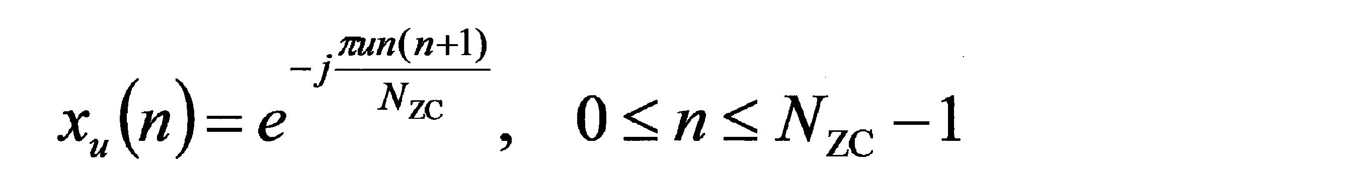
ランダムアクセスプリアンブル(ランダムアクセスプリアンブルの系列)xu,v(n)は以下の数式(2)によって与えられる。Cvは、サイクリックシフトの値である。X mod Yは、XをYで割ったときの余りを出力する関数である。
The random access preamble (sequence of random access preambles) x u, v (n) is given by the following equation (2). Cv is a cyclic shift value. X mod Y is a function that outputs the remainder when X is divided by Y.
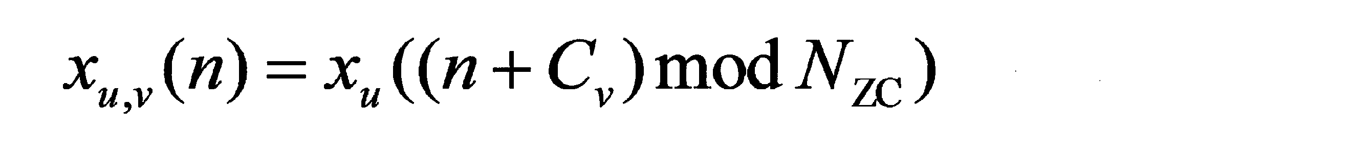
図1において、上りリンクの無線通信では、以下の上りリンク物理シグナルが用いられる。上りリンク物理シグナルは、上位層から出力された情報を送信するために使用されないが、物理層によって使用される。
・上りリンク参照信号(Uplink Reference Signal: UL RS) In FIG. 1, the following uplink physical signals are used in uplink wireless communication. Uplink physical signals are not used to transmit information output from higher layers, but are used by the physical layer.
・ Uplink Reference Signal (UL RS)
・上りリンク参照信号(Uplink Reference Signal: UL RS) In FIG. 1, the following uplink physical signals are used in uplink wireless communication. Uplink physical signals are not used to transmit information output from higher layers, but are used by the physical layer.
・ Uplink Reference Signal (UL RS)
本実施形態において、以下の2つのタイプの上りリンク参照信号が用いられる。
・DMRS(Demodulation Reference Signal)
・SRS(Sounding Reference Signal) In this embodiment, the following two types of uplink reference signals are used.
DMRS (Demodulation Reference Signal)
・ SRS (Sounding Reference Signal)
・DMRS(Demodulation Reference Signal)
・SRS(Sounding Reference Signal) In this embodiment, the following two types of uplink reference signals are used.
DMRS (Demodulation Reference Signal)
・ SRS (Sounding Reference Signal)
DMRSは、PUSCHまたはPUCCHの送信に関連する。DMRSは、PUSCHまたはPUCCHと時間多重される。基地局装置3は、PUSCHまたはPUCCHの伝搬路補正を行なうためにDMRSを使用する。以下、PUSCHとDMRSを共に送信することを、単にPUSCHを送信すると称する。以下、PUCCHとDMRSを共に送信することを、単にPUCCHを送信すると称する。
DMRS is related to transmission of PUSCH or PUCCH. DMRS is time-multiplexed with PUSCH or PUCCH. The base station apparatus 3 uses DMRS to perform propagation channel correction for PUSCH or PUCCH. Hereinafter, transmitting both PUSCH and DMRS is simply referred to as transmitting PUSCH. Hereinafter, transmitting both PUCCH and DMRS is simply referred to as transmitting PUCCH.
SRSは、PUSCHまたはPUCCHの送信に関連しない。基地局装置3は、チャネル状態の測定のためにSRSを用いてもよい。SRSは、上りリンクサブフレームにおけるサブフレームの最後のSC-FDMAシンボル、または、UpPTSにおけるSC-FDMAシンボルにおいて送信される。
SRS is not related to PUSCH or PUCCH transmission. The base station apparatus 3 may use SRS for measuring the channel state. The SRS is transmitted in the last SC-FDMA symbol of the subframe in the uplink subframe or the SC-FDMA symbol in UpPTS.
図1において、基地局装置3から端末装置1への下りリンクの無線通信では、以下の下りリンク物理チャネルが用いられる。下りリンク物理チャネルは、上位層から出力された情報を送信するために、物理層によって使用される。
・PBCH(Physical Broadcast Channel)
・PCFICH(Physical Control Format Indicator Channel)
・PHICH(Physical Hybrid automatic repeat request Indicator Channel)
・PDCCH(Physical Downlink Control Channel)
・EPDCCH(Enhanced Physical Downlink Control Channel)
・PDSCH(Physical Downlink Shared Channel)
・PMCH(Physical Multicast Channel) In FIG. 1, the following downlink physical channels are used in downlink wireless communication from thebase station apparatus 3 to the terminal apparatus 1. The downlink physical channel is used by the physical layer to transmit information output from the higher layer.
・ PBCH (Physical Broadcast Channel)
・ PCFICH (Physical Control Format Indicator Channel)
・ PHICH (Physical Hybrid automatic repeat request Indicator Channel)
・ PDCCH (Physical Downlink Control Channel)
・ EPDCCH (Enhanced Physical Downlink Control Channel)
・ PDSCH (Physical Downlink Shared Channel)
・ PMCH (Physical Multicast Channel)
・PBCH(Physical Broadcast Channel)
・PCFICH(Physical Control Format Indicator Channel)
・PHICH(Physical Hybrid automatic repeat request Indicator Channel)
・PDCCH(Physical Downlink Control Channel)
・EPDCCH(Enhanced Physical Downlink Control Channel)
・PDSCH(Physical Downlink Shared Channel)
・PMCH(Physical Multicast Channel) In FIG. 1, the following downlink physical channels are used in downlink wireless communication from the
・ PBCH (Physical Broadcast Channel)
・ PCFICH (Physical Control Format Indicator Channel)
・ PHICH (Physical Hybrid automatic repeat request Indicator Channel)
・ PDCCH (Physical Downlink Control Channel)
・ EPDCCH (Enhanced Physical Downlink Control Channel)
・ PDSCH (Physical Downlink Shared Channel)
・ PMCH (Physical Multicast Channel)
PBCHは、端末装置1で共通に用いられるマスターインフォメーションブロック(Master Information Block: MIB, Broadcast Channel: BCH)を報知するために用いられる。MIBは、40ms間隔で送信され、MIBは10ms周期で繰り返し送信される。具体的には、SFN mod 4 = 0を満たす無線フレームにおけるサブフレーム0においてMIBの初期送信が行なわれ、他の全ての無線フレームにおけるサブフレーム0においてMIBの再送信(repetition)が行なわれる。SFN(system frame number)は無線フレームの番号である。MIBはシステム情報である。例えば、MIBは、SFNを示す情報を含む。
The PBCH is used to broadcast a master information block (Master Information Block: MIB, Broadcast Channel: BCH) commonly used in the terminal device 1. MIBs are transmitted at 40 ms intervals, and MIBs are repeatedly transmitted at 10 ms intervals. Specifically, the MIB is initially transmitted in subframe 0 in a radio frame satisfying SFN mod 4 = 0, and the MIB is retransmitted in subframe 0 in all other radio frames. SFN (system frame number) is a radio frame number. MIB is system information. For example, the MIB includes information indicating SFN.
PCFICHは、PDCCHの送信に用いられる領域(OFDMシンボル)を指示する情報を送信するために用いられる。
PCFICH is used for transmitting information indicating a region (OFDM symbol) used for transmission of PDCCH.
PHICHは、基地局装置3が受信した上りリンクデータ(Uplink Shared Channel: UL-SCH)に対するHARQインディケータを送信するために用いられる。HARQインディケータは、HARQ-ACKを示す。
PHICH is used to transmit a HARQ indicator for uplink data (Uplink Shared Channel: UL-SCH) received by the base station apparatus 3. The HARQ indicator indicates HARQ-ACK.
PDCCHおよびEPDCCHは、下りリンク制御情報(Downlink Control Information: DCI)を送信するために用いられる。下りリンク制御情報を、DCIフォーマットとも称する。下りリンク制御情報は、下りリンクグラント(downlink grant)および上りリンクグラント(uplink grant)を含む。下りリンクグラントは、下りリンクアサインメント(downlink assignment)または下りリンク割り当て(downlink allocation)とも称する。
PDCCH and EPDCCH are used to transmit downlink control information (Downlink Control Information: DCI). The downlink control information is also referred to as a DCI format. The downlink control information includes a downlink grant (downlink grant) and an uplink grant (uplink grant). The downlink grant is also referred to as downlink assignment (downlink allocation) or downlink assignment (downlink allocation).
1つの下りリンクグラントは、1つのサービングセル内の1つのPDSCHのスケジューリングに用いられる。下りリンクグラントは、該下りリンクグラントが送信されたサブフレームと同じサブフレーム内のPDSCHのスケジューリングに用いられる。
One downlink grant is used for scheduling one PDSCH in one serving cell. The downlink grant is used for scheduling the PDSCH in the same subframe as the subframe in which the downlink grant is transmitted.
1つの上りリンクグラントは、1つのサービングセル内の1つのPUSCHのスケジューリングに用いられる。上りリンクグラントは、該上りリンクグラントが送信されたサブフレームより4つ以上後のサブフレーム内のPUSCHのスケジューリングに用いられる。
One uplink grant is used for scheduling one PUSCH in one serving cell. The uplink grant is used for scheduling PUSCH in a subframe that is four or more times after the subframe in which the uplink grant is transmitted.
下りリンクグラント、または、上りリンクグラントに付加されるCRCパリティビットは、C-RNTI(Cell-Radio Network Temporary Identifier)、Temporary C-RNTI、SPS(Semi Persistent Scheduling)C-RNTI、RA-RNTI(Random Access-Radio Network Temporary Identifier)によってスクランブルされる。C-RNTIおよびSPS C-RNTIは、セル内において端末装置を識別するための識別子である。Temporary C-RNTIは、コンテンションベースランダムアクセスプロシージャの間に用いられる。RA-RNTIは、ランダムアクセスレスポンスのスケジューリングのために用いられる。RNTIによってスクランブルされたCRCパリティビットが付加された上りリンクグラントを、RNTIに対する上りリンクグラント、RNTIに対応する上りリンクグラントとも称する。RNTIによってスクランブルされたCRCパリティビットが付加された上りリンクグラントを含むPDCCHを、RNTIに対するPDCCH、RNTIに対応するPDCCH、RNTI宛てのPDCCH、RNTIを含むPDCCHとも称する。
CRC parity bits added to the downlink grant or uplink grant include C-RNTI (Cell-Radio Network Temporary Identifier), Temporary C-RNTI, SPS (Semi Persistent Scheduling) C-RNTI, RA-RNTI (Random Access-Radio (Network-Temporary (Identifier)). C-RNTI and SPS C-RNTI are identifiers for identifying a terminal device in a cell. Temporary C-RNTI is used during contention-based random access procedures. RA-RNTI is used for scheduling of random access responses. The uplink grant to which the CRC parity bit scrambled by the RNTI is added is also referred to as an uplink grant for the RNTI and an uplink grant corresponding to the RNTI. A PDCCH including an uplink grant to which a CRC parity bit scrambled by RNTI is added is also referred to as a PDCCH for RNTI, a PDCCH corresponding to RNTI, a PDCCH addressed to RNTI, and a PDCCH including RNTI.
C-RNTIは、1つのサブフレームにおけるPDSCHまたはPUSCHを制御するために用いられる。端末装置1は、C-RNTIによってスクランブルされたCRCパリティビットが付加される上りリンクグラントを含むPDCCHの検出に基づいて、トランスポートブロックを含むPUSCHを送信してもよい。該トランスポートブロックの再送信は、C-RNTIによってスクランブルされたCRCパリティビットが付加される上りリンクグラントを含むPDCCHによって指示されてもよい。
C-RNTI is used to control PDSCH or PUSCH in one subframe. The terminal device 1 may transmit the PUSCH including the transport block based on the detection of the PDCCH including the uplink grant to which the CRC parity bit scrambled by the C-RNTI is added. The retransmission of the transport block may be indicated by a PDCCH including an uplink grant to which a CRC parity bit scrambled by C-RNTI is added.
SPS C-RNTIは、PDSCHまたはPUSCHのリソースを周期的に割り当てるために用いられる。端末装置1は、SPS C-RNTIによってスクランブルされたCRCパリティビットが付加される上りリンクグラントを含むPDCCHの検出し、該上りリンクグラントがSPS活性化コマンドとして有効であると判断された場合、該上りリンクグラントを設定された上りリンクグラント(configured uplink grant)としてストアする。端末装置1のMAC層は、該設定された上りリンクグラントが周期的に発生するとみなす。該設定された上りリンクグラントが発生するとみなされるサブフレームは、第1の周期と第1のオフセットによって与えられる。端末装置1は、基地局装置3から、該第1の周期を示す情報を受信する。該周期的に割り当てられるPUSCHで送信されたトランスポートブロックの再送信は、SPS C-RNTIによってスクランブルされたCRCパリティビットが付加される上りリンクグラントによって指示される。該設定された上りリンクグラントを、MAC(Medium Access Control)によって設定された上りリンクグラント、または、第1の設定された上りリンクグラントとも称する。
SPS C-RNTI is used to periodically allocate PDSCH or PUSCH resources. When the terminal device 1 detects the PDCCH including the uplink grant to which the CRC parity bit scrambled by the SPS C-RNTI is added and determines that the uplink grant is valid as the SPS activation command, the terminal device 1 Store the uplink grant as a configured uplink grant (configured uplink grant). The MAC layer of the terminal device 1 considers that the set uplink grant occurs periodically. The subframe in which the configured uplink grant is considered to be generated is given by the first period and the first offset. The terminal device 1 receives information indicating the first period from the base station device 3. Retransmission of transport blocks transmitted on the periodically allocated PUSCH is indicated by an uplink grant to which a CRC parity bit scrambled by the SPS C-RNTI is added. The set uplink grant is also referred to as an uplink grant set by MAC (Medium Access Control) or a first set uplink grant.
PDSCHは、下りリンクデータ(Downlink Shared Channel: DL-SCH)を送信するために用いられる。PDSCHは、ランダムアクセスメッセージ2(ランダムアクセスレスポンス)を送信するために用いられる。PDSCHは、ハンドオーバコマンドを送信するために用いられる。PDSCHは、初期アクセスのために用いられるパラメータを含むシステム情報を送信するために用いられる。
PDSCH is used to transmit downlink data (Downlink Shared Channel: DL-SCH). The PDSCH is used to transmit a random access message 2 (random access response). The PDSCH is used for transmitting a handover command. The PDSCH is used to transmit system information including parameters used for initial access.
PMCHは、マルチキャストデータ(Multicast Channel: MCH)を送信するために用いられる。
PMCH is used to transmit multicast data (Multicast Channel: MCH).
図1において、下りリンクの無線通信では、以下の下りリンク物理シグナルが用いられる。下りリンク物理シグナルは、上位層から出力された情報を送信するために使用されないが、物理層によって使用される。
・同期信号(Synchronization signal: SS)
・下りリンク参照信号(Downlink Reference Signal: DL RS) In FIG. 1, the following downlink physical signals are used in downlink wireless communication. The downlink physical signal is not used to transmit information output from the upper layer, but is used by the physical layer.
・ Synchronization signal (SS)
・ Downlink Reference Signal (DL RS)
同期信号は、端末装置1が下りリンクの周波数領域および時間領域の同期をとるために用いられる。同期信号は、PSS(Primary Synchronization Signal)、および、SSS(Second Synchronization Signal)を含む。
The synchronization signal is used for the terminal device 1 to synchronize the downlink frequency domain and time domain. The synchronization signal includes PSS (Primary Synchronization Signal) and SSS (Second Synchronization Signal).
下りリンク参照信号は、端末装置1が下りリンク物理チャネルの伝搬路補正を行なうために用いられる。下りリンク参照信号は、端末装置1が下りリンクのチャネル状態情報を算出するために用いられる。
The downlink reference signal is used for the terminal device 1 to correct the propagation path of the downlink physical channel. The downlink reference signal is used for the terminal device 1 to calculate downlink channel state information.
本実施形態において、以下の7つのタイプの下りリンク参照信号が用いられる。
・CRS(Cell-specific Reference Signal)
・PDSCHに関連するURS(UE-specific Reference Signal)
・EPDCCHに関連するDMRS(Demodulation Reference Signal)
・NZP CSI-RS(Non-Zero Power Chanel State Information - Reference Signal)
・ZP CSI-RS(Zero Power Chanel State Information - Reference Signal)
・MBSFN RS(Multimedia Broadcast and Multicast Service over Single Frequency Network Reference signal)
・PRS(Positioning Reference Signal) In this embodiment, the following seven types of downlink reference signals are used.
-CRS (Cell-specific Reference Signal)
-URS (UE-specific Reference Signal) related to PDSCH
DMRS (Demodulation Reference Signal) related to EPDCCH
NZP CSI-RS (Non-Zero Power Chanel State Information-Reference Signal)
・ ZP CSI-RS (Zero Power Chanel State Information-Reference Signal)
MBSFN RS (Multimedia Broadcast and Multicast Service over Single Frequency Network Reference signal)
・ PRS (Positioning Reference Signal)
下りリンク物理チャネルおよび下りリンク物理シグナルを総称して、下りリンク信号と称する。上りリンク物理チャネルおよび上りリンク物理シグナルを総称して、上りリンク信号と称する。下りリンク物理チャネルおよび上りリンク物理チャネルを総称して、物理チャネルと称する。下りリンク物理シグナルおよび上りリンク物理シグナルを総称して、物理シグナルと称する。
The downlink physical channel and the downlink physical signal are collectively referred to as a downlink signal. The uplink physical channel and the uplink physical signal are collectively referred to as an uplink signal. The downlink physical channel and the uplink physical channel are collectively referred to as a physical channel. The downlink physical signal and the uplink physical signal are collectively referred to as a physical signal.
BCH、MCH、UL-SCHおよびDL-SCHは、トランスポートチャネルである。媒体アクセス制御(Medium Access Control: MAC)層で用いられるチャネルをトランスポートチャネルと称する。MAC層で用いられるトランスポートチャネルの単位を、トランスポートブロック(transport block: TB)またはMAC PDU(Protocol Data Unit)とも称する。MAC層においてトランスポートブロック毎にHARQ(Hybrid Automatic Repeat reQuest)の制御が行なわれる。トランスポートブロックは、MAC層が物理層に渡す(deliver)データの単位である。物理層において、トランスポートブロックはコードワードにマップされ、コードワード毎に符号化処理が行なわれる。
BCH, MCH, UL-SCH and DL-SCH are transport channels. A channel used in a medium access control (Medium Access Control: MAC) layer is referred to as a transport channel. A transport channel unit used in the MAC layer is also referred to as a transport block (transport block: TB) or a MAC PDU (Protocol Data Unit). In the MAC layer, HARQ (HybridbrAutomatic Repeat reQuest) is controlled for each transport block. The transport block is a unit of data that the MAC layer delivers to the physical layer. In the physical layer, the transport block is mapped to a code word, and an encoding process is performed for each code word.
基地局装置3と端末装置1は、上位層(higher layer)において信号をやり取り(送受信)する。例えば、基地局装置3と端末装置1は、無線リソース制御(RRC: Radio Resource Control)層において、RRCシグナリング(RRC message: Radio Resource Control message、RRC information: Radio Resource Control informationとも称される)を送受信してもよい。また、基地局装置3と端末装置1は、媒体アクセス制御(MAC: Medium Access Control)層において、MAC CE(Control Element)を送受信してもよい。ここで、RRCシグナリング、および/または、MAC CEを、上位層の信号(higher layer signaling)とも称する。
The base station device 3 and the terminal device 1 exchange (transmit / receive) signals in a higher layer. For example, the base station device 3 and the terminal device 1 transmit and receive RRC signaling (RRC message: Radio Resource Control message, RRC information: also called Radio Resource Control information) in a radio resource control (RRC: Radio Resource Control) layer. May be. The base station device 3 and the terminal device 1 may transmit and receive MAC CE (Control Element) in a medium access control (MAC: Medium Access Control) layer. Here, RRC signaling and / or MAC CE is also referred to as higher layer signaling.
PUSCHおよびPDSCHは、RRCシグナリング、および、MAC CEを送信するために用いられる。ここで、基地局装置3からPDSCHで送信されるRRCシグナリングは、セル内における複数の端末装置1に対して共通のシグナリングであってもよい。基地局装置3からPDSCHで送信されるRRCシグナリングは、ある端末装置1に対して専用のシグナリング(dedicated signalingまたはUE specific signalingとも称する)であってもよい。セルスペシフィックパラメータは、セル内における複数の端末装置1に対して共通のシグナリング、または、ある端末装置1に対して専用のシグナリングを用いて送信されてもよい。UEスペシフィックパラメータは、ある端末装置1に対して専用のシグナリングを用いて送信されてもよい。
PUSCH and PDSCH are used to transmit RRC signaling and MAC CE. Here, the RRC signaling transmitted by the PDSCH from the base station apparatus 3 may be common signaling for a plurality of terminal apparatuses 1 in the cell. The RRC signaling transmitted from the base station device 3 on the PDSCH may be dedicated signaling for a certain terminal device 1 (also referred to as dedicated signaling or UE specific signaling). The cell specific parameter may be transmitted using common signaling for a plurality of terminal devices 1 in a cell or dedicated signaling for a certain terminal device 1. The UE specific parameter may be transmitted to a certain terminal device 1 using dedicated signaling.
以下、本実施形態における装置の構成について説明する。
Hereinafter, the configuration of the apparatus according to the present embodiment will be described.
図4は、本実施形態の端末装置1の構成を示す概略ブロック図である。図示するように、端末装置1は、上位層処理部101、制御部103、受信部105、送信部107および、送受信アンテナ109を含んで構成される。上位層処理部101は、無線リソース制御部1011、スケジューリング部1013を含んで構成される。受信部105は、復号化部1051、復調部1053、多重分離部1055、無線受信部1057とチャネル測定部1059を含んで構成される。送信部107は、符号化部1071、PUSCH生成部1073、PUCCH生成部1075、多重部1077、無線送信部1079と上りリンク参照信号生成部10711を含んで構成される。
FIG. 4 is a schematic block diagram showing the configuration of the terminal device 1 of the present embodiment. As illustrated, the terminal device 1 includes an upper layer processing unit 101, a control unit 103, a receiving unit 105, a transmitting unit 107, and a transmission / reception antenna 109. The upper layer processing unit 101 includes a radio resource control unit 1011 and a scheduling unit 1013. The reception unit 105 includes a decoding unit 1051, a demodulation unit 1053, a demultiplexing unit 1055, a radio reception unit 1057, and a channel measurement unit 1059. The transmission unit 107 includes an encoding unit 1071, a PUSCH generation unit 1073, a PUCCH generation unit 1075, a multiplexing unit 1077, a radio transmission unit 1079, and an uplink reference signal generation unit 10711.
上位層処理部101は、ユーザの操作等により生成された上りリンクデータを、送信部107に出力する。また、上位層処理部101は、媒体アクセス制御(MAC: Medium Access Control)層、パケットデータ統合プロトコル(Packet Data Convergence Protocol: PDCP)層、無線リンク制御(Radio Link Control: RLC)層、無線リソース制御(Radio Resource Control: RRC)層の処理を行なう。また、上位層処理部101はPDCCHで受信された下りリンク制御情報などに基づき、受信部105、および送信部107の制御を行なうために制御情報を生成し、制御部103に出力する。
The upper layer processing unit 101 outputs uplink data generated by a user operation or the like to the transmission unit 107. The upper layer processing unit 101 includes a medium access control (MAC: Medium Access Control) layer, a packet data integration protocol (Packet Data Convergence Protocol: PDCP) layer, a radio link control (Radio Link Control: RLC) layer, and radio resource control. Process the (Radio Resource Control: RRC) layer. Further, upper layer processing section 101 generates control information for controlling receiving section 105 and transmitting section 107 based on downlink control information received by PDCCH, and outputs the control information to control section 103.
上位層処理部101が備える無線リソース制御部1011は、自装置の各種設定情報の管理を行なう。例えば、無線リソース制御部1011は、設定されたサービングセルの管理を行なう。また、無線リソース制御部1011は、上りリンクの各チャネルに配置される情報を生成し、送信部107に出力する。
The radio resource control unit 1011 included in the upper layer processing unit 101 manages various setting information of the own device. For example, the radio resource control unit 1011 manages the set serving cell. Also, the radio resource control unit 1011 generates information arranged in each uplink channel and outputs the information to the transmission unit 107.
上位層処理部101が備えるスケジューリング部1013は、受信部105を介して受信した下りリンク制御情報を記憶する。スケジューリング部1013は、上りリンクグラントを受信したサブフレームから4つ、または3つ後のサブフレームにおいて、受信された上りリンクグラントに従ってPUSCHを送信するよう、制御部103を介して送信部107を制御する。スケジューリング部1013は、下りリンクグラントを受信したサブフレームにおいて、受信された下りリンクグラントに従ってPDSCHを受信するよう、制御部103を介して受信部105を制御する。
The scheduling unit 1013 included in the higher layer processing unit 101 stores the downlink control information received via the receiving unit 105. The scheduling unit 1013 controls the transmission unit 107 via the control unit 103 so as to transmit the PUSCH according to the received uplink grant in the subframe that is four or three after the subframe that has received the uplink grant. To do. The scheduling unit 1013 controls the reception unit 105 via the control unit 103 so as to receive the PDSCH according to the received downlink grant in the subframe that has received the downlink grant.
制御部103は、上位層処理部101からの制御情報に基づいて、受信部105、および送信部107の制御を行なう制御信号を生成する。制御部103は、生成した制御信号を受信部105、および送信部107に出力して受信部105、および送信部107の制御を行なう。
The control unit 103 generates a control signal for controlling the receiving unit 105 and the transmitting unit 107 based on the control information from the higher layer processing unit 101. Control unit 103 outputs the generated control signal to receiving unit 105 and transmitting unit 107 to control receiving unit 105 and transmitting unit 107.
受信部105は、制御部103から入力された制御信号に従って、送受信アンテナ109を介して基地局装置3から受信した受信信号を、分離、復調、復号し、復号した情報を上位層処理部101に出力する。
The receiving unit 105 separates, demodulates, and decodes the received signal received from the base station apparatus 3 via the transmission / reception antenna 109 according to the control signal input from the control unit 103, and sends the decoded information to the upper layer processing unit 101. Output.
無線受信部1057は、送受信アンテナ109を介して受信した下りリンクの信号を直交復調し、直交復調されたアナログ信号をディジタル信号に変換する。無線受信部1057は、ディジタル信号に対して高速フーリエ変換(Fast Fourier Transform: FFT)を行い、周波数領域の信号を抽出する。無線受信部1057は、周波数領域の信号を多重分離部1055に出力する。ここで、周波数領域の信号は、サブキャリアインデックスk、および、シンボルインデックスlに対応する複素数値シンボルとして表現される。
The radio reception unit 1057 performs orthogonal demodulation on the downlink signal received via the transmission / reception antenna 109, and converts the orthogonally demodulated analog signal into a digital signal. The wireless reception unit 1057 performs fast Fourier transform (FFT) on the digital signal to extract a frequency domain signal. Radio receiving section 1057 outputs a frequency domain signal to demultiplexing section 1055. Here, the signal in the frequency domain is expressed as a complex value symbol corresponding to the subcarrier index k and the symbol index l.
多重分離部1055は、無線受信部1057より入力される周波数領域の信号を、PDCCH、PDSCH、および下りリンク参照信号に分離する。多重分離部1055は、分離した下りリンク参照信号をチャネル測定部1059に出力する。また、多重分離部1055は、分離したPDCCHおよびPDSCHを復調部1053に出力する。
The demultiplexing unit 1055 demultiplexes the frequency domain signal input from the radio receiving unit 1057 into a PDCCH, a PDSCH, and a downlink reference signal. The demultiplexing unit 1055 outputs the separated downlink reference signal to the channel measuring unit 1059. Further, demultiplexing section 1055 outputs the separated PDCCH and PDSCH to demodulation section 1053.
復調部1053は、PDCCH、および、PDSCHに対して、QPSK、16QAM(Quadrature Amplitude Modulation)、64QAM等の変調方式に対する復調を行ない、復号化部1051へ出力する。
Demodulation section 1053 demodulates PDCCH and PDSCH with respect to modulation schemes such as QPSK, 16QAM (Quadrature Amplitude Modulation), 64QAM, and outputs the result to decoding section 1051.
復号化部1051は、下りリンクデータの復号を行い、復号した下りリンクデータを上位層処理部101へ出力する。チャネル測定部1059は、下りリンク参照信号から下りリンクの伝搬路の推定値を算出し、多重分離部1055へ出力する。チャネル測定部1059は、チャネル状態情報を算出し、尚且つ、チャネル状態情報を上位層処理部101へ出力する。
The decoding unit 1051 decodes the downlink data and outputs the decoded downlink data to the higher layer processing unit 101. Channel measurement section 1059 calculates an estimated value of the downlink propagation path from the downlink reference signal, and outputs the estimated value to demultiplexing section 1055. The channel measurement unit 1059 calculates channel state information and outputs the channel state information to the upper layer processing unit 101.
送信部107は、制御部103から入力された制御信号に従って、上りリンク参照信号を生成し、上位層処理部101から入力された上りリンクデータや上りリンク制御情報を符号化および変調し、PUCCH、PUSCH、および、上りリンク参照信号を多重し、送受信アンテナ109を介して基地局装置3に送信する。
The transmission unit 107 generates an uplink reference signal according to the control signal input from the control unit 103, encodes and modulates uplink data and uplink control information input from the higher layer processing unit 101, and PUCCH, The PUSCH and the uplink reference signal are multiplexed and transmitted to the base station apparatus 3 via the transmission / reception antenna 109.
送信部107において、PUSCHの送信に用いられるOFDMシンボルの数は、少なくともランダムアクセス手順に基づき与えられてもよい。また、PUSCHの送信に用いられるOFDMシンボルの数は、少なくとも、PUSCH送信が対応するランダムアクセス手順のタイプ/フォームに基づき与えられてもよい。また、PUSCHの送信に用いられるOFDMシンボルの数は、少なくともランダムアクセスプリアンブルのフォーマットに基づき与えられてもよい。また、PUSCHの送信に用いられるOFDMシンボルの数は、ランダムアクセスプリアンブルのフォーマットごとに与えられてもよい。また、PUSCHの送信に用いられるOFDMシンボルの数は、上位層の信号に少なくとも基づき与えられてもよい。ランダムアクセス手順のタイプ/フォームの説明は後述する。
In the transmission unit 107, the number of OFDM symbols used for PUSCH transmission may be given based on at least a random access procedure. Also, the number of OFDM symbols used for PUSCH transmission may be given based at least on the type / form of random access procedure to which the PUSCH transmission corresponds. Further, the number of OFDM symbols used for PUSCH transmission may be given based on at least the format of the random access preamble. Further, the number of OFDM symbols used for PUSCH transmission may be given for each format of the random access preamble. Further, the number of OFDM symbols used for PUSCH transmission may be given based at least on higher layer signals. The type / form of the random access procedure will be described later.
符号化部1071は、上位層処理部101から入力された上りリンク制御情報と上りリンクデータを符号化し、符号化ビットをPUSCH生成部1073および/またはPUCCH生成部1075に出力する。
The encoding unit 1071 encodes the uplink control information and the uplink data input from the higher layer processing unit 101, and outputs the encoded bits to the PUSCH generation unit 1073 and / or the PUCCH generation unit 1075.
符号化部1071は、上りリンクデータを符号化し、符号化ビット系列を生成する。また、符号化部1071は、PUSCH初期送信のためのSC-FDMAシンボル数NPUSCH-initial
symbを計算する。ここで、PUSCH初期送信とは、符号化ビット系列を含むトランスポートブロックの初期送信のために用いられるPUSCHを示す。また、符号化部1071は、該SC-FDMAシンボル数NPUSCH-initial
symbに少なくとも基づき、符号化ビット系列をインターリーブ(順序変更、配置換え、並び替え)して第1の系列を生成する。第1の系列は、PUSCH生成部1073に入力される。ここで、PUSCHの初期送信のためのSC-FDMAシンボル数NPUSCH-initial
symbの計算方法は後述される。
The encoding unit 1071 encodes uplink data and generates an encoded bit sequence. Also, encoding section 1071 calculates SC-FDMA symbol count N PUSCH-initial symb for PUSCH initial transmission. Here, PUSCH initial transmission refers to PUSCH used for initial transmission of a transport block including a coded bit sequence. Also, the encoding unit 1071 generates a first sequence by interleaving (order changing, rearranging, rearranging) the encoded bit sequence based at least on the SC-FDMA symbol number N PUSCH-initial symb . The first sequence is input to the PUSCH generation unit 1073. Here, a method of calculating the number of SC-FDMA symbols N PUSCH-initial symb for initial PUSCH transmission will be described later.
ここで、符号化ビット系列のインターリーブは、符号化ビット系列の並び替えを行うことであってもよい。符号化ビット系列の並び替えは、少なくともPUSCH初期送信のためのSC-FDMAシンボル数に基づき与えられてもよい。ここで、該符号化ビット系列のインターリーブのために、行列(matrix)が用いられてもよい。行列の列はSC-FDMAシンボルに対応している。行列の1つのエレメントは、1つの符号化変調シンボルに対応している。符号化変調シンボルはX個の符号化ビットのグループである。Xは、トランスポートブロック(上りリンクデータ)に対する変調次数(modulation order Qm)である。1つの符号化変調シンボルから、1つの複素数値シンボルが生成される。
Here, the interleaving of the encoded bit sequence may be a rearrangement of the encoded bit sequence. The rearrangement of the coded bit sequence may be given based on at least the number of SC-FDMA symbols for PUSCH initial transmission. Here, a matrix may be used for interleaving the coded bit sequence. The matrix columns correspond to SC-FDMA symbols. One element of the matrix corresponds to one coded modulation symbol. A coded modulation symbol is a group of X coded bits. X is the modulation order (modulation order Q m ) for the transport block (uplink data). One complex-valued symbol is generated from one coded modulation symbol.
図5は、本実施形態の符号化部1071による符号化ビット系列のインターリーブの例を示した図である。図5に示す一例において、縦軸(または、行列の行)は、サブキャリア数に対応する軸である。例えば、行数Rrowは、Rrow=Htotal/Cmuxで与えられる。ここで、Htotalは、Htotal=H1+QRIによって与えられる。ここで、H1は、第1の系列における符号化変調シンボルの数である。PUSCHでCQIが送信される場合、H1は、第1の系列における符号化変調シンボルの数とCQIの符号化ビット系列のための符号化変調シンボルの数の和により与えられてもよい。また、QRIは、RIの符号化ビット系列の符号化変調シンボルの数である。PUSCHでRIが送信されない場合、QRI=0である。また、第1の系列に対応するトランスポートブロックの送信のために用いられるレイヤ数がNLの場合、行数Rrowは、Rrow=NL*Htotal/Cmuxで与えられる。ここで、Cmuxは、Cmux=NPUSCH
symbで与えられる。また、PUSCHのSC-FDMAシンボルの数NPUSCH
symbは、NPUSCH
symb=NPUSCH-initial
symbで与えられる。図5に示す一例では、Cmux=12の例を示している。
FIG. 5 is a diagram illustrating an example of interleaving of encoded bit sequences by the encoding unit 1071 of the present embodiment. In the example shown in FIG. 5, the vertical axis (or matrix row) is an axis corresponding to the number of subcarriers. For example, the row number R row is given by R row = H total / C mux . Here, H total is given by H total = H 1 + Q RI . Here, H 1 is the number of coded modulation symbols in the first sequence. When CQI is transmitted on PUSCH, H 1 may be given by the sum of the number of coded modulation symbols in the first sequence and the number of coded modulation symbols for the coded bit sequence of CQI. Also, Q RI is the number of coded modulation symbols of the coded bit sequence of RI. If RI is not transmitted on PUSCH, Q RI = 0. When the number of layers used for transmission of the transport block corresponding to the first stream is N L , the number of rows R row is given by R row = N L * H total / C mux . Here, C mux is given by C mux = N PUSCH symb . Further, the number N PUSCH symb of PUSCH SC-FDMA symbols is given by N PUSCH symb = N PUSCH-initial symb . In the example shown in FIG. 5, an example of C mux = 12 is shown.
図5において、まず、符号化ビット系列は、X個の符号化ビットのグループごとに、実線で示される向きに(行単位に)マップされる。ここで、マップすることは、書き出すこと(Write)であってもよい。次いで、X個の符号化ビットのグループごとにマップされた系列は、点線で示される向きに(列単位に)出力され、第1の系列が生成される。ここで、出力することは、読み出すこと(Read)であってもよい。
In FIG. 5, first, the coded bit sequence is mapped in the direction indicated by the solid line (in units of rows) for each group of X coded bits. Here, mapping may be writing (Write). Next, the sequence mapped for each group of X encoded bits is output in the direction indicated by the dotted line (in units of columns) to generate the first sequence. Here, outputting may be reading (Read).
PUSCH生成部1073において、図5のそれぞれのエレメントに配置されるX個の符号化ビットのグループにより形成される符号化変調シンボルが所定の変調方式に基づき変調されることにより、1つの複素数値シンボルが生成される。また、PUSCH生成部1073において、図5の各列に対応する複数の複素数値シンボルは、ともに離散フーリエ変換(Transform Precoding)され、第2の系列が生成される。第2の系列は、多重部1077に出力される。
In the PUSCH generation unit 1073, one complex value symbol is obtained by modulating an encoded modulation symbol formed by a group of X encoded bits arranged in each element of FIG. 5 based on a predetermined modulation scheme. Is generated. In addition, in the PUSCH generation unit 1073, a plurality of complex-valued symbols corresponding to each column in FIG. 5 are subjected to discrete Fourier transform (Transform Precoding), and a second sequence is generated. The second series is output to multiplexing section 1077.
PUCCH生成部1075は、符号化部1071から入力された上りリンク制御情報(HARQ-ACK、CQI、RI等)の符号化ビットに基づいて、PUCCHの信号を生成し、生成したPUCCHの信号を多重部1077へ出力する。
The PUCCH generation unit 1075 generates a PUCCH signal based on the encoded bits of the uplink control information (HARQ-ACK, CQI, RI, etc.) input from the encoding unit 1071, and multiplexes the generated PUCCH signal Output to the unit 1077.
上りリンク参照信号生成部10711は上りリンク参照信号を生成し、生成した上りリンク参照信号を多重部1077へ出力する。
The uplink reference signal generation unit 10711 generates an uplink reference signal and outputs the generated uplink reference signal to the multiplexing unit 1077.
多重部1077は、制御部103から入力された制御信号に従って、PUSCH生成部1073から入力された信号、および/または、PUCCH生成部1075から入力された信号、および/または、上りリンク参照信号生成部10711から入力された上りリンク参照信号を、送信アンテナポート毎に上りリンクのリソースエレメントに多重する。多重部1077は、多重された信号を無線送信部1079に入力する。
The multiplexing unit 1077 is a signal input from the PUSCH generation unit 1073 and / or a signal input from the PUCCH generation unit 1075 and / or an uplink reference signal generation unit according to the control signal input from the control unit 103. The uplink reference signal input from 10711 is multiplexed to the uplink resource element for each transmission antenna port. The multiplexing unit 1077 inputs the multiplexed signal to the wireless transmission unit 1079.
図6は、本実施形態の多重部1077がPUSCH生成部1073から入力される第2の系列のリソースマッピングの一例を示す図である。図6において、縦軸は周波数(サブキャリアインデックス k)を示し、横軸は時間(シンボルインデックス l)を示す。また、第2の系列は、点線の矢印に示されるように、各リソースエレメントに列単位でマップされる。つまり、第2の系列は、リソースエレメントに周波数方向にマップされる(Frequency first mapping)。ここで、第2の系列がマップされるリソースエレメントは、少なくともPUSCHの送信のために割り当てられるリソースブロックに含まれるリソースエレメントである。また、第2の系列は、PUSCHの送信のために割り当てられるリソースブロックに含まれ、かつ、所定の条件を満たすリソースエレメントにマップされなくてもよい。例えば、図6において、斜線で示されるリソースエレメントにDMRSがマップされる場合、第2の系列は斜線で示されるリソースエレメントにマップされない。また、図6において、格子線で示されるリソースエレメントにSRSがマップされる場合、第2の系列は格子線で示されるリソースエレメントにマップされない。第2の系列がリソースエレメントにマップされる具体的な方法は後述される。
FIG. 6 is a diagram illustrating an example of the second series resource mapping input from the PUSCH generation unit 1073 by the multiplexing unit 1077 according to the present embodiment. In FIG. 6, the vertical axis represents frequency (subcarrier index k) and the horizontal axis represents time (symbol index l). Further, the second series is mapped to each resource element in units of columns, as indicated by dotted arrows. That is, the second sequence is mapped to the resource element in the frequency direction (Frequency first mapping). Here, the resource element to which the second sequence is mapped is a resource element included in at least a resource block allocated for PUSCH transmission. In addition, the second sequence may be included in a resource block allocated for PUSCH transmission and may not be mapped to a resource element that satisfies a predetermined condition. For example, in FIG. 6, when DMRS is mapped to resource elements indicated by diagonal lines, the second sequence is not mapped to resource elements indicated by diagonal lines. Further, in FIG. 6, when the SRS is mapped to the resource element indicated by the grid line, the second series is not mapped to the resource element indicated by the grid line. A specific method for mapping the second sequence to the resource element will be described later.
無線送信部1079は、多重された信号を逆高速フーリエ変換(Inverse Fast Fourier Transform: IFFT)して、ベースバンドのディジタル信号を生成し、ベースバンドのディジタル信号をアナログ信号に変換し、アナログ信号から中間周波数の同相成分および直交成分を生成し、中間周波数帯域に対する余分な周波数成分を除去し、中間周波数の信号を高周波数の信号に変換(アップコンバート: up convert)し、余分な周波数成分を除去し、電力増幅し、送受信アンテナ109に出力して送信する。
The wireless transmission unit 1079 generates a baseband digital signal by performing inverse fast Fourier transform (Inverse Fastier Transform: IFFT) on the multiplexed signal, converts the baseband digital signal into an analog signal, and converts the analog signal from the analog signal. Generates in-phase and quadrature components of intermediate frequency, removes extra frequency component for intermediate frequency band, converts intermediate frequency signal to high frequency signal (up-convert: up convert), removes extra frequency component The power is amplified and output to the transmission / reception antenna 109 for transmission.
図7は、本実施形態の基地局装置3の構成を示す概略ブロック図である。図示するように、基地局装置3は、上位層処理部301、制御部303、受信部305、送信部307、および、送受信アンテナ309、を含んで構成される。また、上位層処理部301は、無線リソース制御部3011とスケジューリング部3013を含んで構成される。また、受信部305は、データ復調/復号部3051、制御情報復調/復号部3053、多重分離部3055、無線受信部3057とチャネル測定部3059を含んで構成される。また、送信部307は、符号化部3071、変調部3073、多重部3075、無線送信部3077と下りリンク参照信号生成部3079を含んで構成される。
FIG. 7 is a schematic block diagram showing the configuration of the base station apparatus 3 of the present embodiment. As illustrated, the base station apparatus 3 includes an upper layer processing unit 301, a control unit 303, a reception unit 305, a transmission unit 307, and a transmission / reception antenna 309. The upper layer processing unit 301 includes a radio resource control unit 3011 and a scheduling unit 3013. The reception unit 305 includes a data demodulation / decoding unit 3051, a control information demodulation / decoding unit 3053, a demultiplexing unit 3055, a wireless reception unit 3057, and a channel measurement unit 3059. The transmission unit 307 includes an encoding unit 3071, a modulation unit 3073, a multiplexing unit 3075, a radio transmission unit 3077, and a downlink reference signal generation unit 3079.
上位層処理部301は、媒体アクセス制御(MAC: Medium Access Control)層、パケットデータ統合プロトコル(Packet Data Convergence Protocol: PDCP)層、無線リンク制御(Radio Link Control: RLC)層、無線リソース制御(Radio Resource Control: RRC)層の処理を行なう。また、上位層処理部301は、受信部305、および送信部307の制御を行なうために制御情報を生成し、制御部303に出力する。
The upper layer processing unit 301 includes a medium access control (MAC: Medium Access Control) layer, a packet data integration protocol (Packet Data Convergence Protocol: PDCP) layer, a radio link control (Radio Link Control: RLC) layer, a radio resource control (Radio). Resource (Control: RRC) layer processing. Further, upper layer processing section 301 generates control information for controlling receiving section 305 and transmitting section 307 and outputs the control information to control section 303.
上位層処理部301が備える無線リソース制御部3011は、PDSCHに配置される下りリンクデータ、RRCシグナル、MAC CE(Control Element)を生成し、又は上位ノードから取得し、スケジューリング部3013に出力する。また、無線リソース制御部3011は、端末装置1各々の各種設定情報の管理を行う。例えば、無線リソース制御部3011は、端末装置1に設定したサービングセルの管理などを行なう。
The radio resource control unit 3011 included in the higher layer processing unit 301 generates downlink data, RRC signal, and MAC CE (Control Element) arranged in the PDSCH, or acquires them from the upper node and outputs them to the scheduling unit 3013. Further, the radio resource control unit 3011 manages various setting information of each terminal device 1. For example, the radio resource control unit 3011 performs management of the serving cell set in the terminal device 1 and the like.
上位層処理部301が備えるスケジューリング部3013は、端末装置1に割り当てるPUSCHやPUCCHの無線リソースの管理を行う。スケジューリング部3013は、端末装置1にPUSCHの無線リソースを割り当てた場合には、PUSCHの無線リソースの割り当てを示す上りリンクグラントを生成し、生成した上りリンクグラントを送信部307へ出力する。
The scheduling unit 3013 included in the higher layer processing unit 301 manages PUSCH and PUCCH radio resources allocated to the terminal device 1. When the PUSCH radio resource is allocated to the terminal device 1, the scheduling unit 3013 generates an uplink grant indicating the allocation of the PUSCH radio resource, and outputs the generated uplink grant to the transmission unit 307.
制御部303は、上位層処理部301からの制御情報に基づいて、受信部305、および送信部307の制御を行なう制御信号を生成する。制御部303は、生成した制御信号を受信部305、および送信部307に出力して受信部305、および送信部307の制御を行なう。
The control unit 303 generates a control signal for controlling the reception unit 305 and the transmission unit 307 based on the control information from the higher layer processing unit 301. The control unit 303 outputs the generated control signal to the reception unit 305 and the transmission unit 307 and controls the reception unit 305 and the transmission unit 307.
受信部305は、制御部303から入力された制御信号に従って、送受信アンテナ309を介して端末装置1から受信した受信信号を分離、復調、復号し、復号した情報を上位層処理部301に出力する。
The receiving unit 305 separates, demodulates and decodes the received signal received from the terminal device 1 via the transmission / reception antenna 309 according to the control signal input from the control unit 303, and outputs the decoded information to the higher layer processing unit 301. .
無線受信部3057は、送受信アンテナ309を介して受信された上りリンクの信号を直交復調し、直交復調されたアナログ信号をディジタル信号に変換する。無線受信部3057は、ディジタル信号に対して高速フーリエ変換(Fast Fourier Transform: FFT)を行い、周波数領域の信号を抽出し多重分離部3055に出力する。
The radio reception unit 3057 orthogonally demodulates the uplink signal received via the transmission / reception antenna 309, and converts the orthogonally demodulated analog signal into a digital signal. The radio reception unit 3057 performs fast Fourier transform (FFT) on the digital signal, extracts a frequency domain signal, and outputs the signal to the demultiplexing unit 3055.
多重分離部3055は、無線受信部3057から入力された信号をPUCCH、PUSCH、上りリンク参照信号などの信号に分離する。尚、この分離は、予め基地局装置3が無線リソース制御部3011で決定し、各端末装置1に通知した上りリンクグラントに含まれる無線リソースの割り当て情報に基づいて行なわれる。多重分離部3055は、チャネル測定部3059から入力された伝搬路の推定値から、PUCCH/sPUCCHとPUSCH/sPUSCHの伝搬路の補償を行なう。また、多重分離部3055は、分離した上りリンク参照信号をチャネル測定部3059に出力する。
The demultiplexing unit 3055 demultiplexes the signal input from the radio receiving unit 3057 into signals such as PUCCH, PUSCH, and uplink reference signal. Note that this separation is performed based on radio resource allocation information included in the uplink grant that is determined in advance by the radio resource control unit 3011 by the base station device 3 and notified to each terminal device 1. The demultiplexing unit 3055 compensates for the propagation paths of the PUCCH / sPUCCH and the PUSCH / sPUSCH based on the propagation path estimation value input from the channel measurement unit 3059. Further, the demultiplexing unit 3055 outputs the separated uplink reference signal to the channel measurement unit 3059.
多重分離部3055が無線受信部3057から入力された信号をPUCCH、PUSCH、上りリンク参照信号などの信号に分離する方法は、端末装置1が備える多重部1077のリソースマッピングの方法に対応するため、説明を省略する。
The method of demultiplexing unit 3055 demultiplexing the signal input from radio receiving unit 3057 into signals such as PUCCH, PUSCH, and uplink reference signal corresponds to the resource mapping method of multiplexing unit 1077 included in terminal apparatus 1. Description is omitted.
多重分離部3055は、分離したPUCCHとPUSCHの信号から、上りリンクデータの複素数値シンボルと上りリンク制御情報の複素数値シンボルを取得する。多重分離部3055は、PUSCHの信号から取得した上りリンクデータの複素数値シンボルをデータ復調/復号部3051へ出力する。多重分離部3055は、PUCCHの信号またはPUSCHの信号から取得した上りリンク制御情報の複素数値シンボルを制御情報復調/復号部3053へ出力する。
The demultiplexing unit 3055 acquires the complex value symbol of the uplink data and the complex value symbol of the uplink control information from the separated PUCCH and PUSCH signals. The demultiplexing unit 3055 outputs the complex value symbol of the uplink data acquired from the PUSCH signal to the data demodulation / decoding unit 3051. The demultiplexing unit 3055 outputs the PUCCH signal or the complex value symbol of the uplink control information acquired from the PUSCH signal to the control information demodulation / decoding unit 3053.
チャネル測定部3059は、多重分離部3055から入力された上りリンク参照信号から伝搬路の推定値、チャネルの品質などを測定し、多重分離部3055および上位層処理部301に出力する。
The channel measurement unit 3059 measures an estimated value of the propagation path, channel quality, and the like from the uplink reference signal input from the demultiplexing unit 3055, and outputs it to the demultiplexing unit 3055 and the upper layer processing unit 301.
データ復調/復号部3051は、多重分離部3055から入力された上りリンクデータの複素数値シンボルから上りリンクデータを復号する。データ復調/復号部3051は、復号された上りリンクデータを上位層処理部301へ出力する。
The data demodulation / decoding unit 3051 decodes the uplink data from the complex value symbol of the uplink data input from the demultiplexing unit 3055. The data demodulation / decoding unit 3051 outputs the decoded uplink data to the higher layer processing unit 301.
データ復調/復号部3051が多重分離部3055から入力された上りリンクデータの複素数値シンボルから上りリンクデータを復号する方法は、端末装置1が備える符号化部1071の動作に対応するため、説明を省略する。
The method of decoding uplink data from the complex value symbol of the uplink data input from the demultiplexing unit 3055 by the data demodulating / decoding unit 3051 corresponds to the operation of the encoding unit 1071 included in the terminal device 1, and therefore will be described. Omitted.
制御情報復調/復号部3053は、多重分離部3055から入力された上りリンク制御情報の複素数値シンボルから上りリンク制御情報を復号する。制御情報復調/復号部3053は、復号した上りリンク制御情報を上位層処理部301へ出力する。
The control information demodulation / decoding unit 3053 decodes the uplink control information from the complex value symbols of the uplink control information input from the demultiplexing unit 3055. The control information demodulation / decoding unit 3053 outputs the decoded uplink control information to the higher layer processing unit 301.
送信部307は、制御部303から入力された制御信号に従って、下りリンク参照信号を生成し、上位層処理部301から入力された下りリンク制御情報、下りリンクデータを符号化、および変調し、PDCCH、PDSCH、および下りリンク参照信号を多重して、送受信アンテナ309を介して端末装置1に信号を送信する。
The transmission unit 307 generates a downlink reference signal according to the control signal input from the control unit 303, encodes and modulates the downlink control information and downlink data input from the higher layer processing unit 301, and performs PDCCH , The PDSCH, and the downlink reference signal are multiplexed, and the signal is transmitted to the terminal device 1 via the transmission / reception antenna 309.
符号化部3071は、上位層処理部301から入力された下りリンク制御情報、および、下りリンクデータの符号化を行なう。変調部3073は、符号化部3071から入力された符号化ビットをQPSK、16QAM、64QAM等の変調方式で変調する。
The encoding unit 3071 encodes downlink control information and downlink data input from the higher layer processing unit 301. The modulation unit 3073 modulates the coded bits input from the coding unit 3071 using a modulation scheme such as QPSK, 16QAM, or 64QAM.
下りリンク参照信号生成部3079は下りリンク参照信号として生成する。多重部3075は、各チャネルの変調シンボルと下りリンク参照信号を多重する。
The downlink reference signal generation unit 3079 generates a downlink reference signal. Multiplexer 3075 multiplexes the modulation symbols and downlink reference signals for each channel.
無線送信部3077は、多重された変調シンボルなどを逆高速フーリエ変換(Inverse Fast Fourier Transform: IFFT)して、OFDM方式の変調を行い、ベースバンドのディジタル信号を生成し、ベースバンドのディジタル信号をアナログ信号に変換し、アナログ信号から中間周波数の同相成分および直交成分を生成し、中間周波数帯域に対する余分な周波数成分を除去し、中間周波数の信号を高周波数の信号に変換(アップコンバート: upconvert)し、余分な周波数成分を除去し、電力増幅し、送受信アンテナ309に出力して送信する。
Radio transmission section 3077 performs inverse fast Fourier transform (Inverse Fastier Transform: IFFT) on the modulated modulation symbols and the like to perform OFDM modulation, generate a baseband digital signal, and convert the baseband digital signal to Converts to an analog signal, generates in-phase and quadrature components of the intermediate frequency from the analog signal, removes excess frequency components for the intermediate frequency band, and converts the intermediate frequency signal to a high-frequency signal (up-convert: upconvert) Then, excess frequency components are removed, power amplification is performed, and output to the transmission / reception antenna 309 is transmitted.
以下、ランダムアクセス手順について詳しく説明をする。ランダムアクセス手順は、コンテンションベースランダムアクセス手順(contention based random access procedure)、および、非コンテンションベースランダムアクセス手順(non-contention based random access procedure)を含む。コンテンションベースランダムアクセス手順は、2ステップコンテンションベースランダムアクセス手順(2 step contention based random access procedure)、および、4ステップコンテンションベースランダムアクセス手順(4 step contention based random access procedure)を含む。すなわち、ランダムアクセス手順のタイプ/フォームは、2ステップコンテンションベース、4ステップコンテンションベース、および、非コンテンションベースを含んでもよい。
Hereinafter, the random access procedure will be described in detail. The random access procedure includes a contention-based random access procedure (contention-based access procedure) and a non-contention basednonrandom access procedure. The contention-based random access procedure includes a two-step contention-based random access procedure (2 step contention based random access procedure) and a four-step contention-based random access procedure (4 step contention based random access procedure). That is, the type / form of random access procedure may include a two-step contention base, a four-step contention base, and a non-contention base.
図8は、本実施形態における4ステップコンテンションベースランダムアクセス手順の一例を示す図である。4ステップコンテンションベースランダムアクセス手順は、第1のステップ(600)、第2のステップ(602)、第3のステップ(604)、および、第4のステップ(606)を含む。
FIG. 8 is a diagram showing an example of a 4-step contention-based random access procedure in the present embodiment. The four-step contention-based random access procedure includes a first step (600), a second step (602), a third step (604), and a fourth step (606).
第1のステップ(600)において、端末装置1は、ランダムアクセスプリアンブルを送信する。ランダムアクセスプリアンブルは、PRACHに含まれる。第1のステップ(600)において、端末装置1のMAC層自身が、ランダムアクセスプリアンブルのインデックスを選択する。すなわち、第1のステップ(600)において、基地局装置3は、ランダムアクセスプリアンブルのインデックスを端末装置1に通知しない。
In the first step (600), the terminal device 1 transmits a random access preamble. The random access preamble is included in the PRACH. In the first step (600), the MAC layer itself of the terminal device 1 selects an index of the random access preamble. That is, in the first step (600), the base station device 3 does not notify the terminal device 1 of the index of the random access preamble.
第2のステップ(602)において、端末装置1は、ランダムアクセスレスポンスを受信する。ランダムアクセスレスポンスは、PDSCHに含まれる。ここで、ランダムアクセスレスポンスを含むPDSCHのスケジューリングのために、RA-RNTIに対するPDCCHが用いられる。RA-RNTIの値は、第1のステップ(600)においてランダムアクセスプリアンブルの送信のために用いられるPRACHのリソースに基づいて与えられてもよい。ランダムアクセスレスポンスは、ランダムアクセスプリアンブルのインデックスを示すランダムアクセスプリアンブル識別子、上りリンクグラント、Temporary C-RNTIを示す情報、および、タイミングアドバンスを示す情報を含む。端末装置1は、ランダムアクセスレスポンスが、第1のステップ(600)において送信されたランダムアクセスプリアンブルに対応するランダムアクセスプリアンブル識別子を含んでいる場合、ランダムアクセスレスポンスの受信に成功したとみなす。
In the second step (602), the terminal device 1 receives a random access response. The random access response is included in the PDSCH. Here, PDCCH for RA-RNTI is used for scheduling of PDSCH including a random access response. The value of RA-RNTI may be given based on the PRACH resources used for transmission of the random access preamble in the first step (600). The random access response includes a random access preamble identifier indicating an index of a random access preamble, information indicating an uplink grant, Temporary C-RNTI, and information indicating a timing advance. When the random access response includes a random access preamble identifier corresponding to the random access preamble transmitted in the first step (600), the terminal device 1 considers that the random access response has been successfully received.
第3のステップ(604)において、端末装置1は、端末装置1の識別子を送信する。ここで、端末装置1の識別子はC-RNTIであってもよい。端末装置1の識別子、または、C-RNTIは、PUSCHに含まれる。ここで、端末装置1の識別子、または、C-RNTIに対するPUSCHは、ランダムアクセスレスポンスに含まれる上りリンクグラントによってスケジュールされる。
In the third step (604), the terminal device 1 transmits the identifier of the terminal device 1. Here, the identifier of the terminal device 1 may be C-RNTI. The identifier of the terminal device 1 or C-RNTI is included in the PUSCH. Here, the identifier of the terminal device 1 or the PUSCH for C-RNTI is scheduled by the uplink grant included in the random access response.
第4のステップ(606)において、端末装置1は、コンテンションリゾリューションを受信する。コンテンションリゾリューションは、UEコンテンションリゾリューション識別子、または、C-RNTIであってもよい。端末装置1が第3のステップ(604)のPUSCHにおいてC-RNTIを送信しており、且つ、端末装置1がC-RNTIに対するPDCCHを受信した場合、端末装置1はコンテンションリゾリューションに成功したとみなしてもよく、且つ、ランダムアクセス手順が成功裏に完了したとみなしてもよい。
In the fourth step (606), the terminal device 1 receives the contention resolution. The contention resolution may be a UE contention resolution identifier or C-RNTI. When the terminal device 1 transmits C-RNTI in the PUSCH of the third step (604) and the terminal device 1 receives the PDCCH for C-RNTI, the terminal device 1 succeeds in contention resolution. It may be considered that the random access procedure has been successfully completed.
UEコンテンションリゾリューション識別子を示す情報は、PDSCHに含まれる。ここで、当該PDSCHのスケジューリングのために、Temporary C-RNTIに対するPDCCHが用いられる。(i)端末装置1が第3のステップ(604)のPUSCHにおいてC-RNTIを送信していない、且つ、(ii)端末装置1が第3のステップ(604)のPUSCHにおいて端末装置1の識別子を送信している、且つ、(iii)端末装置1がTemporary C-RNTIに対するPDCCHを受信し、且つ、(iv)当該PDCCHによってスケジュールされるPDSCHにUEコンテンションリゾリューション識別子を示す情報が含まれ、且つ、(v)当該UEコンテンションリゾリューション識別子と第3のステップ(604)において送信された端末装置1の識別子がマッチする場合、端末装置1はコンテンションリゾリューションに成功したとみなしてもよく、且つ、ランダムアクセス手順が成功裏に完了したとみなしてもよい。
Information indicating the UE contention resolution identifier is included in the PDSCH. Here, PDCCH for Temporary C-RNTI is used for scheduling of the PDSCH. (I) The terminal device 1 has not transmitted C-RNTI in the PUSCH of the third step (604), and (ii) the terminal device 1 is the identifier of the terminal device 1 in the PUSCH of the third step (604) And (iii) the terminal device 1 receives the PDCCH for the Temporary C-RNTI, and (iv) the PDSCH scheduled by the PDCCH includes information indicating the UE contention resolution identifier. And (v) if the UE contention resolution identifier matches the identifier of the terminal device 1 transmitted in the third step (604), the terminal device 1 has succeeded in contention resolution. May be considered and the random access procedure has been successfully completed. It may be.
図9は、本実施形態における2ステップコンテンションベースランダムアクセス手順の一例を示す図である。2ステップコンテンションベースランダムアクセス手順は、第1のステップ(700)、および、第2のステップ(702)を含む。
FIG. 9 is a diagram showing an example of a two-step contention-based random access procedure in the present embodiment. The two-step contention based random access procedure includes a first step (700) and a second step (702).
第1のステップ(700)において、ランダムアクセスプリアンブルと端末装置1の識別子を送信する。ここで、端末装置1の識別子はC-RNTIであってもよい。ランダムアクセスプリアンブルは、PRACHに含まれてもよい。端末装置1の識別子は、PUSCHに含まれてもよい。ランダムアクセスプリアンブルと端末装置1の識別子は、同じ1つの物理チャネルに含まれてもよい。第1のステップ(700)において、端末装置1のMAC層自身が、ランダムアクセスプリアンブルのインデックスを選択する。すなわち、第1のステップ(700)において、基地局装置3は、ランダムアクセスプリアンブルのインデックスを端末装置1に通知しない。
In the first step (700), the random access preamble and the identifier of the terminal device 1 are transmitted. Here, the identifier of the terminal device 1 may be C-RNTI. The random access preamble may be included in the PRACH. The identifier of the terminal device 1 may be included in the PUSCH. The random access preamble and the identifier of the terminal device 1 may be included in the same physical channel. In the first step (700), the MAC layer itself of the terminal device 1 selects an index of the random access preamble. That is, in the first step (700), the base station apparatus 3 does not notify the terminal apparatus 1 of the index of the random access preamble.
第1のステップ(700)で端末装置1の識別子の送信のためにPRACH以外の追加されたチャネルが少なくとも用いられる場合、該追加されたチャネルは、PUSCHとも称される。つまり、PUSCHは、第1のステップ(700)で端末装置1の識別子の送信のために少なくとも用いられるPRACH以外のチャネルであってもよい。
In the first step (700), when at least an added channel other than the PRACH is used for transmitting the identifier of the terminal device 1, the added channel is also referred to as a PUSCH. That is, the PUSCH may be a channel other than the PRACH used at least for transmitting the identifier of the terminal device 1 in the first step (700).
2ステップコンテンションベースランダムアクセス手順において、端末装置1の識別子の送信のためにPRACH以外の追加されたチャネルが少なくとも用いられる場合、該追加されたチャネルは、PUSCHとも称される。つまり、2ステップコンテンションベースランダムアクセス手順において、PUSCHは端末装置1の識別子の送信のために少なくとも用いられるPRACH以外のチャネルであってもよい。
In the two-step contention-based random access procedure, when at least an added channel other than the PRACH is used for transmitting the identifier of the terminal device 1, the added channel is also referred to as PUSCH. That is, in the two-step contention-based random access procedure, the PUSCH may be a channel other than the PRACH that is used at least for transmitting the identifier of the terminal device 1.
第2のステップ(702)において、端末装置1は、コンテンションリゾリューションを受信する。コンテンションリゾリューションは、UEコンテンションリゾリューション識別子、または、C-RNTIであってもよい。端末装置1が第1のステップ(700)においてC-RNTIを送信しており、且つ、端末装置1がC-RNTIを含むPDCCHを受信した場合、端末装置1はコンテンションリゾリューションに成功したとみなしてもよく、且つ、ランダムアクセス手順が成功裏に完了したとみなしてもよい。
In the second step (702), the terminal device 1 receives the contention resolution. The contention resolution may be a UE contention resolution identifier or C-RNTI. When the terminal device 1 has transmitted C-RNTI in the first step (700) and the terminal device 1 has received a PDCCH including the C-RNTI, the terminal device 1 has succeeded in contention resolution. And the random access procedure may have been successfully completed.
UEコンテンションリゾリューション識別子は、PDSCHに含まれる。ここで、当該PDSCHのスケジューリングのために、X-RNTIによってスクランブルされたCRCが付加されたDCIフォーマットが用いられてもよい。X-RNTIは、第1のステップ(700)においてランダムアクセスプリアンブルの送信のために用いられるリソース(PRACHのリソース)、および/または、端末装置1の識別子の送信のために用いられるリソース(PUSCHのリソース)に少なくとも基づいて与えられてもよい。X-RNTIは、RA-RNTIであってもよい。
The UE contention resolution identifier is included in the PDSCH. Here, for scheduling of the PDSCH, a DCI format to which a CRC scrambled by X-RNTI is added may be used. The X-RNTI is a resource (PRACH resource) used for transmission of a random access preamble and / or a resource (PUSCH resource) used for transmission of an identifier of the terminal device 1 in the first step (700). Resource). X-RNTI may be RA-RNTI.
(i)端末装置1が第1のステップ(700)においてC-RNTIを送信していない、且つ、(ii)端末装置1が第1のステップ(700)において端末装置1の識別子を送信している、且つ、(iii)端末装置1がX-RNTIに対するPDCCHを受信し、且つ、(iv)当該PDCCHによってスケジュールされるPDSCHにUEコンテンションリゾリューション識別子を示す情報が含まれ、且つ、(v)当該UEコンテンションリゾリューション識別子と第1のステップ(700)において送信された端末装置1の識別子がマッチする場合、端末装置1はコンテンションリゾリューションに成功したとみなしてもよく、且つ、ランダムアクセス手順が成功裏に完了したとみなしてもよい。X-RNTIに対するPDCCHによってスケジュールされるPDSCHは、上りリンクグラント、C-RNTIを示す情報、および、タイミングアドバンスを示す情報の一部、または、全部を含んでもよい。X-RNTIに対するPDCCHによってスケジュールされるPDSCHは、ランダムアクセスプリアンブルのインデックスを示す情報を含まなくてもよい。ここで、端末装置1は、C-RNTIを、C-RNTIを示す情報の値にセットしてもよい。
(I) The terminal device 1 has not transmitted C-RNTI in the first step (700), and (ii) the terminal device 1 has transmitted the identifier of the terminal device 1 in the first step (700). (Iii) the terminal device 1 receives the PDCCH for the X-RNTI, and (iv) the PDSCH scheduled by the PDCCH includes information indicating the UE contention resolution identifier, and ( v) If the UE contention resolution identifier matches the identifier of the terminal device 1 transmitted in the first step (700), the terminal device 1 may be regarded as having succeeded in contention resolution, And it may be considered that the random access procedure has been successfully completed. The PDSCH scheduled by the PDCCH for X-RNTI may include some or all of the uplink grant, information indicating C-RNTI, and information indicating timing advance. The PDSCH scheduled by the PDCCH for X-RNTI may not include information indicating the index of the random access preamble. Here, the terminal device 1 may set C-RNTI to a value of information indicating C-RNTI.
図10は、本実施形態における2ステップコンテンションベースランダムアクセス手順の変形例を示す図である。2ステップコンテンションベースランダムアクセス手順の変形例は、第1のステップ(800)、第2のステップ(802)、第3のステップ(804)、および、第4のステップ(806)を含む。第1のステップ(800)は、第1のステップ(700)と同じである。第2のステップ(802)は第2のステップ(602)と同じである。第3のステップ(804)は、第3のステップ(604)と同じである。第4のステップ(806)は、第4のステップ(606)と同じである。すなわち、2ステップランダムアクセス手順の第1のステップの後に、2ステップコンテンションベースランダムアクセス手順から4ステップコンテンションベースランダムアクセス手順に移行してもよい。
FIG. 10 is a diagram showing a modification of the two-step contention-based random access procedure in the present embodiment. A variation of the two-step contention based random access procedure includes a first step (800), a second step (802), a third step (804), and a fourth step (806). The first step (800) is the same as the first step (700). The second step (802) is the same as the second step (602). The third step (804) is the same as the third step (604). The fourth step (806) is the same as the fourth step (606). That is, after the first step of the two-step random access procedure, the two-step contention-based random access procedure may be shifted to the four-step contention-based random access procedure.
第1のステップ(800)において基地局装置3がランダムアクセスプリアンブルを検出し、且つ、端末装置1の識別子を検出できなかった場合、第2のステップ(802)において基地局装置3はランダムアクセスレスポンスを送信する。すなわち、2ステップランダムアクセス手順の第1のステップにおいて、基地局装置3がランダムアクセスプリアンブルを検出し、且つ、端末装置1の識別子を検出できなかった場合、基地局装置3によって4ステップランダムアクセス手順の第2のステップが開始されてもよい。2ステップランダムアクセス手順の第1のステップにおいて、基地局装置3がランダムアクセスプリアンブル、および、端末装置1の識別子を検出した場合、基地局装置3によって2ステップランダムアクセス手順の第2のステップが開始されてもよい。
When the base station apparatus 3 detects the random access preamble in the first step (800) and the identifier of the terminal apparatus 1 cannot be detected, the base station apparatus 3 detects the random access response in the second step (802). Send. That is, in the first step of the two-step random access procedure, when the base station device 3 detects the random access preamble and cannot detect the identifier of the terminal device 1, the base station device 3 performs the four-step random access procedure. The second step may be started. When the base station device 3 detects the random access preamble and the identifier of the terminal device 1 in the first step of the two-step random access procedure, the base station device 3 starts the second step of the two-step random access procedure. May be.
端末装置1は、2ステップコンテンションベースランダムアクセス手順の第1のステップ(700、800)の後、第2のステップ(702)のコンテンションリゾリューション、および、第2のステップ(802)のランダムアクセスレスポンスをモニタしてもよい。すなわち、第2のステップ(702、802)において、端末装置1は、ランダムアクセスレスポンスに関連するPDCCH、および、コンテンションリゾリューションに関連するPDCCHをモニタしてもよい。ランダムアクセスレスポンスに関連するPDCCHは、RA-RNTIに対するPDCCHであってもよい。コンテンションリゾリューションに関連するPDCCHは、X-RNTIに対するPDCCHであってもよい。
After the first step (700, 800) of the two-step contention-based random access procedure, the terminal device 1 performs the contention resolution of the second step (702) and the second step (802). The random access response may be monitored. That is, in the second step (702, 802), the terminal device 1 may monitor the PDCCH related to the random access response and the PDCCH related to the contention resolution. The PDCCH related to the random access response may be a PDCCH for RA-RNTI. The PDCCH associated with contention resolution may be a PDCCH for X-RNTI.
端末装置1は、4ステップコンテンションベースランダムアクセス手順の第1のステップ(600)の後、第2のステップ(602)のランダムアクセスレスポンスをモニタしてもよい。すなわち、第2のステップ(602)において、端末装置1はランダムアクセスレスポンスに関連するPDCCHをモニタしてもよい。第2のステップ(602)において、端末装置1はコンテンションリゾリューションをモニタしなくてもよい。すなわち、第2のステップ(602)において、端末装置1はコンテンションリゾリューションに関連するPDCCHをモニタしなくてもよい。
The terminal device 1 may monitor the random access response of the second step (602) after the first step (600) of the four-step contention-based random access procedure. That is, in the second step (602), the terminal device 1 may monitor the PDCCH related to the random access response. In the second step (602), the terminal device 1 may not monitor contention resolution. That is, in the second step (602), the terminal device 1 does not have to monitor the PDCCH related to contention resolution.
図11は、本実施形態における非コンテンションベースランダムアクセス手順の一例を示す図である。非コンテンションベースランダムアクセス手順は、第0のステップ(900)、第1のステップ(902)、および、第2のステップ(904)を含む。
FIG. 11 is a diagram showing an example of a non-contention based random access procedure in the present embodiment. The non-contention based random access procedure includes a zero step (900), a first step (902), and a second step (904).
第0のステップ(900)において、端末装置1は、ランダムアクセスプリアンブルの割り当てを受信する。ランダムアクセスプリアンブルの割り当ては、ハンドオーバコマンド、または、C-RNTIに対するPDCCHに含まれてもよい。ランダムアクセスプリアンブルの割り当ては、ランダムアクセスプリアンブルのインデックスを示してもよい。ランダムアクセスプリアンブルの割り当てを含むPDCCHを、PDCCHオーダ、または、ランダムアクセス手順の開始を指示するPDCCHオーダとも称する。
In the 0th step (900), the terminal device 1 receives the assignment of the random access preamble. Random access preamble assignment may be included in a handover command or PDCCH for C-RNTI. The assignment of the random access preamble may indicate an index of the random access preamble. The PDCCH including the allocation of the random access preamble is also referred to as a PDCCH order or a PDCCH order that instructs the start of the random access procedure.
第1のステップ(902)において、端末装置1は、ランダムアクセスプリアンブルの割り当てに基づいてランダムアクセスプリアンブルを選択し、選択したランダムアクセスプリアンブルを送信する。ランダムアクセスプリアンブルは、PRACHに含まれる。第1のステップ(902)において、端末装置1のMAC層自身が、ランダムアクセスプリアンブルのインデックスを選択しない。
In the first step (902), the terminal device 1 selects a random access preamble based on the allocation of the random access preamble and transmits the selected random access preamble. The random access preamble is included in the PRACH. In the first step (902), the MAC layer itself of the terminal device 1 does not select the index of the random access preamble.
第2のステップ(904)において、端末装置1は、ランダムアクセスレスポンスを受信する。ランダムアクセスレスポンスは、PDSCHに含まれる。ここで、ランダムアクセスレスポンスを含むPDSCHのスケジューリングのために、RA-RNTIに対するPDCCHが用いられる。RA-RNTIの値は、第1のステップ(900)においてランダムアクセスプリアンブルの送信のために用いられるPRACHのリソースに基づいて与えられてもよい。ランダムアクセスレスポンスは、ランダムアクセスプリアンブルのインデックスを示すランダムアクセスプリアンブル識別子、上りリンクグラント、Temporary C-RNTIを示す情報、および、タイミングアドバンスを示す情報を含む。ランダムアクセスレスポンスが、第1のステップ(900)において送信されたランダムアクセスプリアンブルに対応するランダムアクセスプリアンブル識別子を含んでいる場合、ランダムアクセスレスポンスの受信に成功したとみなす。端末装置1は、ランダムアクセスレスポンスが、第1のステップ(900)において送信されたランダムアクセスプリアンブルに対応するランダムアクセスプリアンブル識別子を含んでおり、且つ、ランダムアクセスプリアンブルの割り当てが通知されており、且つ、ランダムアクセスプリアンブルのインデックスを端末装置1のMAC自身が選択していない場合、端末装置1はランダムアクセスプロシージャが成功裏に完了したとみなす。
In the second step (904), the terminal device 1 receives a random access response. The random access response is included in the PDSCH. Here, PDCCH for RA-RNTI is used for scheduling of PDSCH including a random access response. The value of RA-RNTI may be given based on the PRACH resources used for transmission of the random access preamble in the first step (900). The random access response includes a random access preamble identifier indicating an index of a random access preamble, information indicating an uplink grant, Temporary C-RNTI, and information indicating a timing advance. If the random access response includes a random access preamble identifier corresponding to the random access preamble transmitted in the first step (900), it is considered that the random access response has been successfully received. The terminal device 1 includes a random access response including a random access preamble identifier corresponding to the random access preamble transmitted in the first step (900), and the allocation of the random access preamble is notified, and When the MAC of the terminal device 1 has not selected the random access preamble index, the terminal device 1 considers that the random access procedure has been completed successfully.
第0のステップ(900)において、ランダムアクセスプリアンブルの割り当てが第1の所定の値を示す場合、端末装置1は、4ステップコンテンションベースランダムアクセス手順を開始してもよい。すなわち、ランダムアクセスプリアンブルのインデックスを端末装置1のMAC自身が選択していない場合は、ランダムアクセスプリアンブルの割り当てが第1の所定の値ではない場合であってもよい。
In the 0th step (900), when the random access preamble assignment indicates the first predetermined value, the terminal device 1 may start the 4-step contention-based random access procedure. That is, when the MAC of the terminal device 1 does not select the random access preamble index, the random access preamble assignment may not be the first predetermined value.
第0のステップ(900)において、ランダムアクセスプリアンブルの割り当てが第2の所定の値を示す場合、端末装置1は、2ステップコンテンションベースランダムアクセス手順を開始してもよい。すなわち、ランダムアクセスプリアンブルのインデックスを端末装置1のMAC自身が選択していない場合は、ランダムアクセスプリアンブルの割り当てが第1の所定の値、および、第2の所定の値の何れとも異なる場合であってもよい。
In the 0th step (900), when the random access preamble assignment indicates the second predetermined value, the terminal device 1 may start the 2-step contention-based random access procedure. That is, when the MAC of the terminal device 1 does not select the random access preamble index, the random access preamble allocation is different from both the first predetermined value and the second predetermined value. May be.
図12は、本実施形態におけるイベントとランダムアクセス手順の形態の対応の一例を示す図である。ランダムアクセス手順は、(イベントi)RRC_IDLEからの初期アクセス、(イベントii)RRCコネクション再確立、(イベントiii)ハンドオーバ、(イベントiv)RRC_CONNECTEDの間の下りリンクデータアライバル、(イベントv)RRC_CONNECTEDの間の上りリンクデータアライバル、および、(イベントvi)セカンダリーTAGのための時間調整のために実行される。(イベントiv)RRC_CONNECTEDの間の下りリンクデータアライバルのためのランダムアクセス手順は、上りリンク同期のステータスが非同期である場合に実行されてもよい。(イベントv)RRC_CONNECTEDの間の上りリンクデータアライバルのためのランダムアクセス手順は、上りリンク同期のステータスが非同期である場合、または、スケジューリングリクエストのためのPUCCHリソースがない場合に実行されてもよい。
FIG. 12 is a diagram showing an example of correspondence between an event and a random access procedure in this embodiment. The random access procedure consists of (event i) initial access from RRC_IDLE, (event ii) RRC connection re-establishment, (event iii) handover, (event iv) downlink data arrival during RRC_CONNECTED, (event v) during RRC_CONNECTED For uplink data arrival and (event vi) time adjustment for secondary TAG. (Event iv) The random access procedure for downlink data arrival during RRC_CONNECTED may be performed when the uplink synchronization status is asynchronous. (Event v) The random access procedure for uplink data arrival during RRC_CONNECTED may be performed when the uplink synchronization status is asynchronous or there is no PUCCH resource for scheduling request.
イベントiからイベントvに関するランダムアクセス手順はプライマリーセルにおいて実行されてもよい。イベントviに関するランダムアクセス手順における第1のステップはセカンダリーセルにおいて実行されてもよい。すなわち、(イベントvi)セカンダリーTAGのための時間調整のために実行されるランダムアクセス手順は、セカンダリーTAGに属するセカンダリーセルにおいて開始される。
The random access procedure regarding event i to event v may be executed in the primary cell. The first step in the random access procedure for event vi may be performed in the secondary cell. That is, (event vi) The random access procedure executed for time adjustment for the secondary TAG is started in the secondary cell belonging to the secondary TAG.
(イベントi)RRC_IDLEからの初期アクセスのためのランダムアクセス手順は、4ステップコンテンションベースランダムアクセス手順、および、2ステップコンテンションベースランダムアクセス手順を含んでもよい。(イベントi)RRC_IDLEからの初期アクセスのためのランダムアクセス手順は、非コンテンションベースランダムアクセス手順を含まなくてもよい。(イベントi)RRC_IDLEからの初期アクセスのためのランダムアクセス手順はRRCによって開始されてもよい。
(Event i) The random access procedure for initial access from RRC_IDLE may include a 4-step contention-based random access procedure and a 2-step contention-based random access procedure. (Event i) The random access procedure for initial access from RRC_IDLE may not include a non-contention based random access procedure. (Event i) A random access procedure for initial access from RRC_IDLE may be initiated by RRC.
(イベントii)RRCコネクション再確立のためのランダムアクセス手順は、4ステップコンテンションベースランダムアクセス手順、および、2ステップコンテンションベースランダムアクセス手順を含んでもよい。(イベントii)RRCコネクション再確立のためのランダムアクセス手順は、非コンテンションベースランダムアクセス手順を含まなくてもよい。(イベントii)RRCコネクション再確立のためのランダムアクセス手順はRRCによって開始されてもよい。
(Event ii) The random access procedure for re-establishing the RRC connection may include a 4-step contention-based random access procedure and a 2-step contention-based random access procedure. (Event ii) The random access procedure for re-establishing the RRC connection may not include a non-contention based random access procedure. (Event ii) The random access procedure for re-establishing the RRC connection may be initiated by the RRC.
ランダムアクセス手順が4ステップコンテンションベースランダムアクセス手順を含むことは、4ステップコンテンションベースランダムアクセス手順がサポートされること、4ステップコンテンションベースランダムアクセス手順が有効であること、または、4ステップコンテンションベースランダムアクセス手順が適用可能であることであってもよい。2ステップコンテンションベースランダムアクセス手順、および、非コンテンションベースランダムアクセス手順に対しても同様である。
The fact that the random access procedure includes a four-step contention-based random access procedure means that the four-step contention-based random access procedure is supported, that the four-step contention-based random access procedure is valid, or that the four-step contention-based random access procedure is valid. It may be that a tension-based random access procedure is applicable. The same applies to the two-step contention-based random access procedure and the non-contention-based random access procedure.
基地局装置3(セル)が送信/報知するシステムインフォメーションは、PRACH情報、ランダムアクセス情報を含んでもよい。PRACH情報は、PRACHのリソースを示す情報、ランダムアクセスプリアンブルに関する物理ルートシーケンスインデックスuに関する情報、および、ランダムアクセスプリアンブルのためのサイクリックシフトCvに関する情報を含んでもよい。物理ルートシーケンスインデックスu、および、サイクリックシフトCvは、ランダムアクセスプリアンブルの系列を決定するために用いられる。ランダムアクセス情報は、ランダムアクセスプリアンブルの数を示す情報、コンテンションベースランダムアクセス手順のためのランダムアクセスプリアンブルの数を示す情報を含んでもよい。また、システムインフォメーションは、2ステップコンテンションベースランダムアクセス手順のための情報を含んでもよい。2ステップコンテンションベースランダムアクセス手順のための情報は、セルにおいて2ステップコンテンションベースランダムアクセス手順がサポートされていることを示す情報、2ステップコンテンションベースランダムアクセス手順の第1のステップにおける端末装置1の識別子を送信するためのリソースを示す情報、2ステップコンテンションベースランダムアクセス手順の第1のステップにおける端末装置1の識別子を含むデータの変調方式を示す情報、および/または、RSRP(Reference Signal Received Power)の閾値を示す情報を含んでもよい。ここで、システムインフォメーションは、非コンテンションベースランダムアクセス手順の第0のステップのためのランダムアクセスプリアンブルの割り当てを含まない。
The system information transmitted / notified by the base station device 3 (cell) may include PRACH information and random access information. PRACH information, information indicating the resource of PRACH, information about the physical root sequence index u about random access preamble, and may contain information about the cyclic shift C v for the random access preamble. The physical root sequence index u and the cyclic shift Cv are used to determine a sequence of random access preambles. The random access information may include information indicating the number of random access preambles and information indicating the number of random access preambles for the contention-based random access procedure. The system information may also include information for a two-step contention based random access procedure. The information for the two-step contention-based random access procedure is information indicating that the two-step contention-based random access procedure is supported in the cell, and the terminal device in the first step of the two-step contention-based random access procedure Information indicating a resource for transmitting one identifier, information indicating a modulation scheme of data including the identifier of the terminal device 1 in the first step of the two-step contention-based random access procedure, and / or RSRP (Reference Signal Information indicating a threshold of (Received Power) may be included. Here, the system information does not include allocation of a random access preamble for the 0th step of the non-contention based random access procedure.
端末装置1は、セルの下りリンク参照信号からRSRPを測定する。端末装置1は、測定したRSRP、および、RSRPの閾値に基づいて、2ステップコンテンションベースランダムアクセス手順および4ステップコンテンションベースランダムアクセス手順の何れか一方を開始してもよい。端末装置1は、測定したRSRPがRSRPの閾値を超えない場合、4ステップコンテンションベースランダムアクセス手順を開始してもよい。端末装置1は、測定したRSRPがRSRPの閾値を超える場合、2ステップコンテンションベースランダムアクセス手順を開始してもよい。
The terminal device 1 measures RSRP from the downlink reference signal of the cell. The terminal device 1 may start one of the 2-step contention-based random access procedure and the 4-step contention-based random access procedure based on the measured RSRP and the RSRP threshold value. If the measured RSRP does not exceed the RSRP threshold, the terminal device 1 may start a 4-step contention-based random access procedure. The terminal device 1 may start a two-step contention-based random access procedure when the measured RSRP exceeds the RSRP threshold.
(イベントiii)ハンドオーバのためのランダムアクセス手順は、4ステップコンテンションベースランダムアクセス手順、2ステップコンテンションベースランダムアクセス手順、および、非コンテンションベースランダムアクセス手順を含んでもよい。ハンドオーバコマンドは、上述したPRACH情報、上述したランダムアクセス情報、上述した2ステップコンテンションベースランダムアクセス手順のための情報、および/または、非コンテンションベースランダムアクセス手順の第0のステップのためのランダムアクセスプリアンブルの割り当てを含んでもよい。
(Event iii) The random access procedure for handover may include a 4-step contention-based random access procedure, a 2-step contention-based random access procedure, and a non-contention-based random access procedure. The handover command includes the above-described PRACH information, the above-described random access information, the information for the above-described two-step contention-based random access procedure, and / or the random for the zeroth step of the non-contention-based random access procedure. Access preamble assignment may also be included.
端末装置1は、ハンドオーバコマンドに含まれる情報に基づいて、4ステップコンテンションベースランダムアクセス手順、2ステップコンテンションベースランダムアクセス手順、および、非コンテンションベースランダムアクセス手順の何れか1つを開始してもよい。
The terminal device 1 starts any one of the 4-step contention-based random access procedure, the 2-step contention-based random access procedure, and the non-contention-based random access procedure based on the information included in the handover command. May be.
端末装置1は、ハンドオーバコマンドにランダムアクセスプリアンブルの割り当てが含まれる場合、非コンテンションベースランダムアクセス手順を開始してもよい。
The terminal device 1 may start a non-contention based random access procedure when the handover command includes assignment of a random access preamble.
端末装置1は、ハンドオーバコマンドにランダムアクセスプリアンブルの割り当てが含まれず、且つ、ハンドオーバコマンドに2ステップコンテンションベースランダムアクセス手順のための情報が含まれる場合、測定したRSRP、および、RSRPの閾値に基づいて、2ステップコンテンションベースランダムアクセス手順および4ステップコンテンションベースランダムアクセス手順の何れか一方を開始してもよい。
If the handover command does not include the assignment of the random access preamble and the handover command includes information for the two-step contention-based random access procedure, the terminal device 1 is based on the measured RSRP and the RSRP threshold value. Thus, one of the two-step contention-based random access procedure and the four-step contention-based random access procedure may be started.
端末装置1は、ハンドオーバコマンドにランダムアクセスプリアンブルの割り当てが含まれず、且つ、ハンドオーバコマンドに2ステップコンテンションベースランダムアクセス手順のための情報が含まれる場合、測定したRSRP、および、RSRPの閾値に基づいて、2ステップコンテンションベースランダムアクセス手順および4ステップコンテンションベースランダムアクセス手順の何れか一方を開始してもよい。ここで、端末装置1は、測定したRSRPがRSRPの閾値を超えない場合、4ステップコンテンションベースランダムアクセス手順を開始してもよい。ここで、端末装置1は、測定したRSRPがRSRPの閾値を超える場合、2ステップコンテンションベースランダムアクセス手順を開始してもよい。
If the handover command does not include the assignment of the random access preamble and the handover command includes information for the two-step contention-based random access procedure, the terminal device 1 is based on the measured RSRP and the RSRP threshold value. Thus, one of the two-step contention-based random access procedure and the four-step contention-based random access procedure may be started. Here, the terminal device 1 may start a 4-step contention-based random access procedure when the measured RSRP does not exceed the RSRP threshold. Here, the terminal device 1 may start a two-step contention-based random access procedure when the measured RSRP exceeds the RSRP threshold.
端末装置1は、ハンドオーバコマンドにランダムアクセスプリアンブルの割り当てが含まれ、且つ、ランダムアクセスプリアンブルの割り当てが第1の所定の値を示す場合、4ステップコンテンションベースランダムアクセス手順を開始してもよい。
The terminal device 1 may start the 4-step contention-based random access procedure when the handover command includes random access preamble assignment and the random access preamble assignment indicates the first predetermined value.
端末装置1は、ハンドオーバコマンドにランダムアクセスプリアンブルの割り当てが含まれ、且つ、ランダムアクセスプリアンブルの割り当てが第2の所定の値を示し、且つ、ハンドオーバコマンドに2ステップコンテンションベースランダムアクセス手順のための情報が含まれる場合、2ステップコンテンションベースランダムアクセス手順を開始してもよい。
The terminal apparatus 1 includes a random access preamble assignment in the handover command, the random access preamble assignment indicates a second predetermined value, and the handover command includes a two-step contention-based random access procedure. If information is included, a two-step contention based random access procedure may be initiated.
端末装置1は、ハンドオーバコマンドにランダムアクセスプリアンブルの割り当てが含まれず、且つ、ハンドオーバコマンドに2ステップコンテンションベースランダムアクセス手順のための情報が含まれない場合、4ステップコンテンションベースランダムアクセス手順を開始してもよい。
The terminal device 1 starts a 4-step contention-based random access procedure when the handover command does not include the assignment of the random access preamble and the handover command does not include information for the 2-step contention-based random access procedure. May be.
(イベントiv)RRC_CONNECTEDの間の下りリンクデータアライバルのためのランダムアクセス手順は、4ステップコンテンションベースランダムアクセス手順、および、非コンテンションベースランダムアクセス手順を含んでもよい。(イベントiv)RRC_CONNECTEDの間の下りリンクデータアライバルのためのランダムアクセス手順は、2ステップコンテンションベースランダムアクセス手順を含まなくてもよい。(イベントiv)RRC_CONNECTEDの間の下りリンクデータアライバルのためのランダムアクセス手順は、PDCCHオーダによって開始される。
(Event iv) The random access procedure for downlink data arrival during RRC_CONNECTED may include a 4-step contention-based random access procedure and a non-contention-based random access procedure. (Event iv) The random access procedure for downlink data arrival during RRC_CONNECTED may not include a two-step contention based random access procedure. (Event iv) The random access procedure for downlink data arrival during RRC_CONNECTED is initiated by the PDCCH order.
PDCCHオーダに含まれるランダムアクセスプリアンブルの割り当てが第1の所定の値以外の値である場合、端末装置1は非コンテンションベースランダムアクセス手順を開始してもよい。PDCCHオーダに含まれるランダムアクセスプリアンブルの割り当てが第1の所定の値である場合、端末装置1は4ステップコンテンションベースランダムアクセス手順を開始してもよい。PDCCHオーダに含まれるランダムアクセスプリアンブルの割り当てが第2の所定の値であったとしても、端末装置1は4ステップコンテンションベースランダムアクセス手順を開始してもよい。
When the allocation of the random access preamble included in the PDCCH order is a value other than the first predetermined value, the terminal device 1 may start the non-contention based random access procedure. When the allocation of the random access preamble included in the PDCCH order is the first predetermined value, the terminal device 1 may start a 4-step contention-based random access procedure. Even if the allocation of the random access preamble included in the PDCCH order is the second predetermined value, the terminal device 1 may start the 4-step contention-based random access procedure.
(イベントv)RRC_CONNECTEDの間の上りリンクデータアライバルのためのランダムアクセス手順は、4ステップコンテンションベースランダムアクセス手順、および、2ステップコンテンションベースランダムアクセス手順を含んでもよい。(イベントv)RRC_CONNECTEDの間の上りリンクデータアライバルのためのランダムアクセス手順は、非コンテンションベースランダムアクセス手順を含まなくてもよい。(イベントv)RRC_CONNECTEDの間の上りリンクデータアライバルのためのランダムアクセス手順は、MAC自身によって開始される。
(Event v) The random access procedure for uplink data arrival during RRC_CONNECTED may include a 4-step contention-based random access procedure and a 2-step contention-based random access procedure. (Event v) The random access procedure for uplink data arrival during RRC_CONNECTED may not include a non-contention based random access procedure. (Event v) The random access procedure for uplink data arrival during RRC_CONNECTED is initiated by the MAC itself.
(イベントvi)セカンダリーTAGのための時間調整のために実行されるランダムアクセス手順は、PDCCHオーダによって開始される。すなわち、セカンダリーセルにおけるランダムアクセス手順の開始を指示するPDCCHオーダに含まれるランダムアクセスプリアンブルの割り当ては第1の所定の値以外の値を示す。
(Event vi) The random access procedure performed for time adjustment for the secondary TAG is initiated by the PDCCH order. That is, the allocation of the random access preamble included in the PDCCH order instructing the start of the random access procedure in the secondary cell indicates a value other than the first predetermined value.
図13は、本実施形態におけるイベントとランダムアクセス手順の形態の対応の別の例を示す図である。ランダムアクセス手順は、(イベントA)RRC、(イベントB)MAC自身、または、(イベントC)PDCCHオーダによって開始される。
FIG. 13 is a diagram showing another example of the correspondence between the event and the random access procedure in this embodiment. The random access procedure is initiated by (Event A) RRC, (Event B) MAC itself, or (Event C) PDCCH order.
(イベントA)RRCによって開始されるランダムアクセス手順は、4ステップコンテンションベースランダムアクセス手順、2ステップコンテンションベースランダムアクセス手順、および、非コンテンションベースランダムアクセス手順を含んでもよい。
(Event A) Random access procedures initiated by RRC may include 4-step contention-based random access procedures, 2-step contention-based random access procedures, and non-contention-based random access procedures.
(イベントB)MAC自身によって開始されるランダムアクセス手順は、4ステップコンテンションベースランダムアクセス手順、および、2ステップコンテンションベースランダムアクセス手順を含んでもよい。(イベントB)MAC自身によって開始されるランダムアクセス手順は、非コンテンションベースランダムアクセス手順を含まなくてもよい。
(Event B) The random access procedure initiated by the MAC itself may include a 4-step contention-based random access procedure and a 2-step contention-based random access procedure. (Event B) The random access procedure initiated by the MAC itself may not include a non-contention based random access procedure.
PDCCHオーダによって開始されるランダムアクセス手順は、4ステップコンテンションベースランダムアクセス手順、非コンテンションベースランダムアクセス手順を含んでもよい。PDCCHオーダによって開始されるランダムアクセス手順は、2ステップコンテンションベースランダムアクセス手順を含まなくてもよい。
The random access procedure initiated by the PDCCH order may include a 4-step contention-based random access procedure and a non-contention-based random access procedure. The random access procedure initiated by the PDCCH order may not include a two-step contention based random access procedure.
(イベントC)PDCCHオーダに基づいてプライマリーセルにおいて開始されるランダムアクセス手順は、4ステップコンテンションベースランダムアクセス手順、非コンテンションベースランダムアクセス手順を含んでもよい。(イベントC)PDCCHオーダに基づいてプライマリーセルにおいて開始されるランダムアクセス手順は、2ステップコンテンションベースランダムアクセス手順を含まなくてもよい。
(Event C) The random access procedure started in the primary cell based on the PDCCH order may include a 4-step contention-based random access procedure and a non-contention-based random access procedure. (Event C) The random access procedure initiated in the primary cell based on the PDCCH order may not include a two-step contention based random access procedure.
(イベントD)PDCCHオーダに基づいてセカンダリーセルにおいて開始されるランダムアクセス手順は、非コンテンションベースランダムアクセス手順を含んでもよい。(イベントD)PDCCHオーダに基づいてセカンダリーセルにおいて開始されるランダムアクセス手順は、4ステップコンテンションベースランダムアクセス手順、および、2ステップコンテンションベースランダムアクセス手順を含まなくてもよい。
(Event D) The random access procedure initiated in the secondary cell based on the PDCCH order may include a non-contention based random access procedure. (Event D) The random access procedure started in the secondary cell based on the PDCCH order may not include the 4-step contention-based random access procedure and the 2-step contention-based random access procedure.
端末装置1が備える符号化部1071における、PUSCHの初期送信のためのSC-FDMAシンボル数NPUSCH-initial
symbの計算方法を説明する。
A method for calculating the SC-FDMA symbol number N PUSCH-initial symb for initial transmission of PUSCH in the encoding unit 1071 provided in the terminal apparatus 1 will be described.
PUSCHの初期送信のためのSC-FDMAシンボル数NPUSCH-initial
symbは、以下の数式(3)に基づき与えられてもよい。
The SC-FDMA symbol number N PUSCH-initial symb for initial transmission of PUSCH may be given based on the following equation (3).

ここで、第1の値NPUSCH
endは、0、または、1以上の値をとる変数であってもよい。また、第2の値NSRSは、0、または、1の値をとる変数であってもよい。また、第3の値NPUSCH
startは、0、または、1の値をとる変数であってもよい。また、第4の値NUL
symbは、スロットあたりのSC-FDMAシンボルの数である。ここで、第1の値NPUSCH
endは、PUSCHに対応する第1の値NPUSCH
endであってもよい。また、第2の値NSRSは、PUSCHに対応する第2の値NSRSであってもよい。また、第3の値NPUSCH
startは、PUSCHに対応する第3の値NPUSCH
startであってもよい。また、第4の値NUL
symbは、PUSCHに対応する第4の値NUL
symbであってもよい。
Here, the first value N PUSCH end may be a variable having a value of 0 or 1 or more. The second value N SRS may be a variable that takes a value of 0 or 1. The third value N PUSCH start may be a variable that takes a value of 0 or 1. The fourth value N UL symb is the number of SC-FDMA symbols per slot. Here, the first value N PUSCH end The may be the first value N PUSCH end The corresponding to PUSCH. The second value N SRS may be a second value N SRS corresponding to the PUSCH. The third value N PUSCH start may be a third value N PUSCH start corresponding to PUSCH. The fourth value N UL symb can be a fourth value N UL symb corresponding to PUSCH.
ここで、PUSCHの初期送信のためのSC-FDMAシンボル数NPUSCH-initial
symbは、第1の値NPUSCH
endに少なくとも基づき与えられてもよい。また、PUSCHの初期送信のためのSC-FDMAシンボル数NPUSCH-initial
symbは、第1の値NPUSCH
endに少なくとも関連していてもよい。
Here, the SC-FDMA symbol number N PUSCH-initial symb for initial transmission of PUSCH may be given based at least on the first value N PUSCH end . Also, the SC-FDMA symbol number N PUSCH-initial symb for initial transmission of PUSCH may be at least related to the first value N PUSCH end .
例えば、条件(A1)の下で、第1の値NPUSCH
endは、1、または、1以上の値であってもよい。また、条件(A2)の下で、第1の値NPUSCH
endは、1であってもよい。また、条件(A3)の下で、第1の値NPUSCH
endは、0であってもよい。
For example, under the condition (A1), the first value N PUSCH end may be 1 or a value of 1 or more. Further, the first value N PUSCH end may be 1 under the condition (A2). Further, the first value N PUSCH end may be 0 under the condition (A3).
ここで、条件(A1)は、第1のステップ(700)においてPUSCHが送信されることを含んでもよい。また、第1のPUSCH送信は、第1のステップ(800)においてPUSCHが送信されることを含んでもよい。
Here, the condition (A1) may include transmission of PUSCH in the first step (700). Also, the first PUSCH transmission may include the PUSCH being transmitted in the first step (800).
また、条件(A1)は、2ステップコンテンションベースランダムアクセス手順においてPUSCHが送信されることを含んでもよい。つまり、条件(A1)は、PRACHによりPUSCHの送信がトリガされることを含んでもよい。また、条件(A1)は、PRACHとPUSCHが同時に送信されることを含んでもよい。また、条件(A1)は、PRACHと同一の送信タイミングにおいてPUSCHが送信されることを含んでもよい。また、条件(A1)は、PRACHと同一の周波数リソース(リソースブロックインデックス)においてPUSCHが送信されることを含んでもよい。また、条件(A1)は、PRACHの送信タイミングに少なくとも基づいてPUSCHが送信されることを含んでもよい。
Further, the condition (A1) may include transmission of PUSCH in a two-step contention-based random access procedure. That is, the condition (A1) may include that transmission of PUSCH is triggered by PRACH. Further, the condition (A1) may include that PRACH and PUSCH are transmitted simultaneously. Further, the condition (A1) may include that the PUSCH is transmitted at the same transmission timing as the PRACH. In addition, the condition (A1) may include that the PUSCH is transmitted on the same frequency resource (resource block index) as the PRACH. Further, the condition (A1) may include that the PUSCH is transmitted based at least on the transmission timing of the PRACH.
また、条件(A1)は、基地局装置3から受信した信号(下りリンク制御情報、および/または、上位層の信号)によりPUSCHの送信がトリガされないことを含んでもよい。条件(A1)は、基地局装置3から受信した信号(下りリンク制御情報、および/または、上位層の信号)によりトリガされるPUSCHの送信以外のPUSCHが送信されることを含んでもよい。つまり、条件(A1)は、端末装置1自身(または、端末装置1のMAC層、または、端末装置1の上位層)によりPUSCHの送信がトリガされることを含んでもよい。また、条件(A1)は、上りリンクグラントなし(グラントフリー)でPUSCHが送信されることを含んでもよい。つまり、条件(A1)は、基地局装置3から受信した上りリンクグラントとは関係なくPUSCHが送信されることを含んでもよい。
Also, the condition (A1) may include that PUSCH transmission is not triggered by a signal (downlink control information and / or higher layer signal) received from the base station apparatus 3. The condition (A1) may include transmission of PUSCH other than PUSCH transmission triggered by a signal (downlink control information and / or higher layer signal) received from the base station apparatus 3. That is, the condition (A1) may include that the PUSCH transmission is triggered by the terminal device 1 itself (or the MAC layer of the terminal device 1 or the upper layer of the terminal device 1). In addition, the condition (A1) may include that the PUSCH is transmitted without an uplink grant (grant-free). That is, the condition (A1) may include that the PUSCH is transmitted regardless of the uplink grant received from the base station apparatus 3.
また、条件(A1)は、上りリンクの送信タイミングに基づかずPUSCHが送信されることを含んでもよい。
Further, the condition (A1) may include the PUSCH being transmitted without being based on the uplink transmission timing.
また、条件(A1)は、下りリンクの送信タイミングに基づいてPUSCHが送信されることを含んでもよい。ここで、下りリンクの送信タイミングに基づいてPUSCHが送信されることは、NTA=0に少なくとも基づき与えられる送信タイミングに基づいてPUSCHが送信されることであってもよい。ここで、PUSCHの送信タイミングは、(NTA+NTA,offset) * Tsで与えられる。つまり、PUSCHの送信タイミングは、下りリンクサブフレームの開始時点から(NTA+NTA,offset) * Ts前に移動したタイミングにより与えられる。ここで、NTA,offsetは、フレーム構成タイプ1において、0である。また、NTA,offsetは、フレーム構成タイプ2において、624である。NTA,offsetは、フレーム構成タイプ3において、624である。
In addition, the condition (A1) may include transmission of PUSCH based on downlink transmission timing. Here, the transmission of the PUSCH based on the downlink transmission timing may be the transmission of the PUSCH based on the transmission timing given based at least on N TA = 0. Here, the transmission timing of PUSCH is given by (N TA + N TA, offset ) * T s . That is, the PUSCH transmission timing is given by the timing of moving from the start of the downlink subframe to (N TA + N TA, offset ) * T s before. Here, N TA, offset is 0 in the frame configuration type 1. Further, N TA, offset is 624 in the frame configuration type 2. N TA, offset is 624 in the frame configuration type 3.
また、条件(A1)は、端末装置1が有効な送信タイミング値(TA value)を有していない場合においてPUSCHが送信されることを含んでもよい。
In addition, the condition (A1) may include that the PUSCH is transmitted when the terminal device 1 does not have a valid transmission timing value (TA value).
つまり、条件(A1)は、条件(a1)から条件(a6)の一部または全部を少なくとも満たすことであってもよい。条件(a1):第1のステップ(700)においてPUSCHが送信されること条件(a2):2ステップコンテンションベースランダムアクセス手順においてPUSCHが送信されること条件(a3):基地局装置3から受信した信号(下りリンク制御情報、および/または、上位層の信号)によりトリガされないPUSCHが送信されること条件(a4):上りリンクの送信タイミングに基づかないPUSCHが送信されること条件(a5):下りリンクの送信タイミングに基づくPUSCHが送信されること条件(a6):端末装置1が有効な送信タイミング値(TA value)を有していない場合においてPUSCHが送信されること
That is, the condition (A1) may satisfy at least a part or all of the conditions (a1) to (a6). Condition (a1): PUSCH is transmitted in the first step (700) Condition (a2): PUSCH is transmitted in the two-step contention-based random access procedure Condition (a3): Received from the base station apparatus 3 Condition (a4): PUSCH that is not triggered by the received signal (downlink control information and / or higher layer signal): Condition that a PUSCH not based on uplink transmission timing is transmitted (a5): Conditions for transmitting PUSCH based on downlink transmission timing (a6): PUSCH is transmitted when terminal apparatus 1 does not have a valid transmission timing value (TA value)
ここで、条件(a1)は、第1のステップ(800)においてPUSCHが送信されること、であってもよい。
Here, the condition (a1) may be that PUSCH is transmitted in the first step (800).
また、条件(a2)は、PRACHによりトリガされるPUSCHが送信されることであってもよい。また、条件(a2)は、PRACHとPUSCHが同時に送信されることであってもよい。また、条件(a2)は、PRACHと同一の送信タイミングにおいてPUSCHが送信されることであってもよい。また、条件(a2)は、PRACHと同一の周波数リソース(リソースブロックインデックス)においてPUSCHが送信されることであってもよい。また、条件(a2)は、PRACHの送信タイミングに少なくとも基づいてPUSCHが送信されることであってもよい。
Also, the condition (a2) may be that PUSCH triggered by PRACH is transmitted. Further, the condition (a2) may be that PRACH and PUSCH are transmitted simultaneously. Further, the condition (a2) may be that PUSCH is transmitted at the same transmission timing as PRACH. Further, the condition (a2) may be that the PUSCH is transmitted in the same frequency resource (resource block index) as the PRACH. Further, the condition (a2) may be that the PUSCH is transmitted based at least on the transmission timing of the PRACH.
また、条件(a3)は、端末装置1自身によりPUSCHの送信がトリガされることであってもよい。また、条件(a3)は、上りリンクグラントなし(グラントフリー)でPUSCHが送信されることであってもよい。
Further, the condition (a3) may be that the PUSCH transmission is triggered by the terminal device 1 itself. The condition (a3) may be that PUSCH is transmitted without uplink grant (grant-free).
また、条件(A2)は、PUSCHがLAAセルにおいて送信され、かつ、PUSCHがサブフレームの最後から2番目のSC-FDMAシンボルまで送信されることが設定され、かつ、PUSCHに対応する第2の値NSRSが0であることを含んでもよい。また、条件(A2)は、端末装置1に対して上りリンク送信をLAAセルにおいて行うことが設定され、かつ、PUSCHをサブフレームの最後から2番目のSC-FDMAシンボルまで送信することが設定され、かつ、PUSCHに対応する第2の値NSRSが0であることを含んでもよい。PUSCHがサブフレームの最後から2番目のSC-FDMAシンボルまで送信されることは、PUSCHが少なくともサブフレームの最後の1つのSC-FDMAシンボルにおいて送信されないことを意味する。サブフレームの最後から2番目のSC-FDMAシンボルまでは、サブフレームの最後から2番目のSC-FDMAシンボルを含む。また、上りリンク送信は、PUSCHの送信であってもよい。
The condition (A2) is set so that PUSCH is transmitted in the LAA cell and PUSCH is transmitted from the end of the subframe to the second SC-FDMA symbol, and the second corresponding to the PUSCH It may include that the value N SRS is zero. Also, the condition (A2) is set to perform uplink transmission in the LAA cell for the terminal device 1 and to transmit PUSCH to the second SC-FDMA symbol from the end of the subframe. And the second value N SRS corresponding to PUSCH may be zero. The transmission of the PUSCH from the end of the subframe to the second SC-FDMA symbol means that the PUSCH is not transmitted in at least the last one SC-FDMA symbol of the subframe. The second SC-FDMA symbol from the last of the subframe includes the second SC-FDMA symbol from the last of the subframe. Further, uplink transmission may be PUSCH transmission.
条件(A2)は、条件(a7)を少なくとも満たし、条件(a1)から条件(a6)の一部または全部を少なくとも満たさないことであってもよい。条件(a7):PUSCHがLAAセルにおいて送信され、かつ、PUSCHがサブフレームの最後から2番目のSC-FDMAシンボルまで送信されることが設定され、かつ、PUSCHに対応する第2の値NSRSが0であること
The condition (A2) may satisfy at least the condition (a7) and not satisfy at least a part or all of the conditions (a1) to (a6). Condition (a7): PUSCH is transmitted in the LAA cell, and PUSCH is set to be transmitted from the end of the subframe to the second SC-FDMA symbol, and the second value N SRS corresponding to PUSCH Is 0
ここで、条件(a7)は、端末装置1に対して上りリンク送信をLAAセルにおいて行うことが設定され、かつ、PUSCHをサブフレームの最後から2番目のSC-FDMAシンボルまで送信することが設定され、かつ、PUSCHに対応する第2の値NSRSが0であることであってもよい。
Here, the condition (a7) is set so that uplink transmission is performed in the LAA cell to the terminal device 1 and PUSCH is transmitted from the end of the subframe to the second SC-FDMA symbol. And the second value N SRS corresponding to PUSCH may be zero.
例えば、条件(A2)は、条件(a7)を満たし、条件(a1)を満たさないことであってもよい。つまり、条件(A2)は、PUSCHがLAAセルにおいて送信され、かつ、PUSCHがサブフレームの最後から2番目のSC-FDMAシンボルまで送信され、かつ、PUSCHに対応する第2の値NSRSが0であり、かつ、第1のステップ(700)以外においてPUSCHが送信されることであってもよい。また、条件(A2)は、条件(a7)を満たし、条件(a2)を満たさないことであってもよい。また、条件(A2)は、条件(a7)を満たし、条件(a1)および条件(a2)を満たさないことであってもよい。その他の条件に対しても同様であるため、説明を省略する。
For example, the condition (A2) may satisfy the condition (a7) and not satisfy the condition (a1). That is, the condition (A2) is that PUSCH is transmitted in the LAA cell, PUSCH is transmitted from the end of the subframe to the second SC-FDMA symbol, and the second value N SRS corresponding to PUSCH is 0. And PUSCH may be transmitted in other than the first step (700). Further, the condition (A2) may satisfy the condition (a7) and not satisfy the condition (a2). Further, the condition (A2) may satisfy the condition (a7) and may not satisfy the condition (a1) and the condition (a2). Since it is the same also about other conditions, description is abbreviate | omitted.
また、条件(A2)は、条件(a8)と条件(a9)の一部または全部を少なくとも満たすことであってもよい。条件(a8):第3のステップ(604)においてPUSCHが送信されること条件(a9):4ステップコンテンションベースランダムアクセス手順においてPUSCHが送信されること
Further, the condition (A2) may satisfy at least a part or all of the condition (a8) and the condition (a9). Condition (a8): PUSCH is transmitted in the third step (604) Condition (a9): PUSCH is transmitted in the 4-step contention-based random access procedure
ここで、条件(a8)は、第3のステップ(804)においてPUSCHが送信されること、であってもよい。
Here, the condition (a8) may be that PUSCH is transmitted in the third step (804).
また、条件(a9)は、ランダムアクセスレスポンスに含まれる上りリンクグラント(ランダムアクセスレスポンスグラント)によりPUSCHの送信がトリガされることであってもよい。
Further, the condition (a9) may be that PUSCH transmission is triggered by an uplink grant (random access response grant) included in the random access response.
つまり、条件(A2)は、条件(a7)から条件(a9)の一部または全部を少なくとも満たし、条件(a1)から条件(a6)の一部または全部を少なくとも満たさないことであってもよい。例えば、条件(A2)は、条件(a7)と条件(a8)を満たし、条件(a1)を満たさなくてもよい。また、条件(A2)は、条件(a7)と条件(a9)を満たし、条件(a3)を満たさなくてもよい。その他の条件に対しても同様であるため、説明を省略する。
That is, the condition (A2) may be that at least a part or all of the conditions (a7) to (a9) are satisfied, and at least a part or all of the conditions (a1) to (a6) are not satisfied. . For example, the condition (A2) satisfies the condition (a7) and the condition (a8), and may not satisfy the condition (a1). Further, the condition (A2) satisfies the condition (a7) and the condition (a9) and does not need to satisfy the condition (a3). Since it is the same also about other conditions, description is abbreviate | omitted.
条件(A3)は、条件(A1)、および/または、条件(A2)を満たさないことであってもよい。
The condition (A3) may not satisfy the condition (A1) and / or the condition (A2).
また、条件(A3)は、条件(a1)から条件(a6)の一部または全部を少なくとも満たさず、かつ、条件(a7)を満たさないことであってもよい。例えば、条件(A3)は、条件(a1)を満たさず、さらに、条件(a7)を満たさないことであってもよい。つまり、条件(A3)は、(i)第1のステップ(700)以外においてPUSCHが送信されることであり、かつ、(ii)端末装置1に対して上りリンク送信をLAAセル以外において行うことが設定される、または、端末装置1に対してPUSCHをサブフレームの最後の2番目のSC-FDMAシンボルまで送信することが設定されない、または、PUSCHに対応する第2の値NSRSが0ではないこと、であってもよい。その他の条件に対しても同様であるため、説明を省略する。ここで、端末装置1に対してPUSCHをサブフレームの最後の2番目のSC-FDMAシンボルまで送信することが設定されないことは、端末装置1に対してPUSCHをサブフレームの最後のSC-FDMAシンボルまで送信することが設定されることであってもよい。
Further, the condition (A3) may not satisfy at least a part or all of the conditions (a1) to (a6) and may not satisfy the condition (a7). For example, the condition (A3) may not satisfy the condition (a1) and may not satisfy the condition (a7). That is, the condition (A3) is that (i) PUSCH is transmitted outside the first step (700), and (ii) uplink transmission to the terminal device 1 is performed outside the LAA cell. Is set, or transmission of the PUSCH up to the last second SC-FDMA symbol of the subframe is not set to the terminal device 1 or when the second value N SRS corresponding to the PUSCH is 0 It may not be. Since it is the same also about other conditions, description is abbreviate | omitted. Here, the fact that transmission of the PUSCH to the last second SC-FDMA symbol in the subframe is not set to the terminal device 1 means that the PUSCH is transmitted to the terminal device 1 in the last SC-FDMA symbol in the subframe. It may be set to transmit until.
また、条件(A3)は、条件(a1)から条件(a6)の一部または全部を少なくとも満たさず、かつ、条件(a7)を満たさず、かつ、条件(a8)から条件(a9)の一部または全部を少なくとも満たすことであってもよい。例えば、条件(A3)は、条件(a1)を満たさず、さらに、条件(a7)を満たさず、かつ、条件(a8)を満たしてもよい。つまり、条件(A3)は、(i)第1のステップ(700)以外においてPUSCHが送信される、かつ、(ii)端末装置1に対して上りリンク送信をLAAセル以外において行うことが設定され、または、端末装置1に対してPUSCHをサブフレームの最後の2番目のSC-FDMAシンボルまで送信することが設定されない、または、第2の値NSRSが0ではなく、(iii)第3のステップ(604)におけるPUSCHの送信であること、であってもよい。その他の条件に対しても同様であるため、説明を省略する。
The condition (A3) does not satisfy at least a part or all of the conditions (a1) to (a6), does not satisfy the condition (a7), and is one of the conditions (a8) to (a9). It may be to fill at least part or all. For example, the condition (A3) may not satisfy the condition (a1), may not satisfy the condition (a7), and may satisfy the condition (a8). In other words, the condition (A3) is set such that (i) PUSCH is transmitted in other than the first step (700), and (ii) uplink transmission is performed to the terminal device 1 in other than the LAA cell. Or the terminal apparatus 1 is not set to transmit the PUSCH up to the last second SC-FDMA symbol of the subframe, or the second value N SRS is not 0 and (iii) the third It may be the transmission of PUSCH in step (604). Since it is the same also about other conditions, description is abbreviate | omitted.
PUSCHの初期送信のためのSC-FDMAシンボル数NPUSCH-initial
symbは、第1の値NPUSCH
endに加えて、第2の値NSRSに少なくとも基づき与えられてもよい。ここで、第2の値NSRSは、所定の条件を少なくとも満たす場合に1である。所定の条件は、条件(a10)から条件(a14)の一部または全部を含んでもよい。例えば、所定の条件は、条件(a10)を満たすことであってもよい。また、所定の条件は条件(a11)を満たすことであってもよい。また、所定の条件は条件(a12)を満たすことであってもよい。また、所定の条件は条件(a13)を満たすことであってもよい。また、所定の条件は条件(a14)を満たすことであってもよい。また、所定の条件は条件(a10)および条件(a11)を満たすことであってもよい。その他の条件に対しても同様であるため、説明を省略する。条件(a10):端末装置1に対して1つの上りリンクセル(ULセル)が設定され、かつ、PUSCHの初期送信とSRSの送信が同一のサブフレームに設定されること(UE configured with one UL cell is configured to send PUSCH and SRS in the same subframe for initial transmission)条件(a11):PUSCHの初期送信とSRSの送信が同一のサービングセルの同一のサブフレームにおいて実施されること(if UE transmits PUSCH and SRS in the same subframe in the same serving cell for initial transmission)条件(a12):PUSCHの初期送信のための帯域(リソース、または周波数リソース)の少なくとも一部がセル固有SRSに設定される帯域と重複すること(the PUSCH resource allocation for initial transmission even partially overlaps with the cell-specific SRS subframe and bandwidth configuration)条件(a13):PUSCHの初期送信のためのサブフレームにおいて、第1のUE固有SRSが設定されること(the subframe for initial transmission in the same serving cell is a UE-specific type-1 SRS subframe)条件(a14):PUSCHの初期送信のためのサブフレームにおいて、第2のUE固有SRSが設定され、かつ、端末装置1に複数のTAGが設定されること(the subframe for initial transmission in the same serving cell is a UE-specific type-0 SRS subframe and the UE is configured with multiple TAGs)
The SC-FDMA symbol number N PUSCH-initial symb for initial transmission of PUSCH may be given based at least on the second value N SRS in addition to the first value N PUSCH end . Here, the second value N SRS is 1 when at least a predetermined condition is satisfied. The predetermined condition may include a part or all of the condition (a10) to the condition (a14). For example, the predetermined condition may be to satisfy the condition (a10). Further, the predetermined condition may be to satisfy the condition (a11). Further, the predetermined condition may satisfy the condition (a12). Further, the predetermined condition may be to satisfy the condition (a13). Further, the predetermined condition may be that the condition (a14) is satisfied. Further, the predetermined condition may be that the condition (a10) and the condition (a11) are satisfied. Since it is the same also about other conditions, description is abbreviate | omitted. Condition (a10): One uplink cell (UL cell) is set for the terminal device 1 and PUSCH initial transmission and SRS transmission are set in the same subframe (UE configured with one UL cell is configured to send PUSCH and SRS in the same subframe for initial transmission) condition (a11): the initial transmission of PUSCH and the transmission of SRS are performed in the same subframe of the same serving cell (if UE transfers PUSCH and SRS in the same subframe in the same serving cell for initial transmission) condition (a12): at least a part of a band (resource or frequency resource) for initial transmission of PUSCH overlaps with a band set in the cell-specific SRS (The PUSCH resource allocation for initial transmission even partially overlaps with the cell-specific SRS subframe and bandwidth configuration) 13): In a subframe for initial transmission of PUSCH, the first UE-specific SRS is set (the subframe for initial transmission in the same serving cell is a UE-specific type-1 SRS subframe) condition (a14 ): In the subframe for initial transmission of PUSCH, the second UE-specific SRS is set, and a plurality of TAGs are set in the terminal device 1 (the subframe for initial transmission in the same serving cell is a UE-specific type-0 SRS subframe and the UE is configured with multiple TAGs)
条件(a12)において、セル固有のSRS帯域は、上位層の信号に含まれる情報に基づき与えられる。また、セル固有SRSのサブフレームは、上位層の信号に含まれる情報に基づき与えられる。
In the condition (a12), the cell-specific SRS band is given based on information included in the higher layer signal. Further, the subframe of the cell-specific SRS is given based on information included in the higher layer signal.
条件(a13)において、第1のUE固有SRSは、非周期的に送信されるSRSのために設定される。また、第1のUE固有SRSのサブフレームは、上位層の信号に含まれる情報に基づき与えられる。非周期的に送信されるSRSは、下りリンク制御情報に含まれる情報によりトリガされる。
In condition (a13), the first UE-specific SRS is set for the SRS transmitted aperiodically. Also, the first UE-specific SRS subframe is given based on information included in the higher layer signal. The SRS transmitted aperiodically is triggered by information included in the downlink control information.
条件(a14)において、第2のUE固有SRSは、周期的に送信されるSRSのために設定される。また、第2のUE固有SRSのサブフレームは、上位層の信号に含まれる情報に基づき与えられる。
In condition (a14), the second UE-specific SRS is set for the periodically transmitted SRS. Also, the second UE-specific SRS subframe is given based on information included in the higher layer signal.
また、PUSCHに対応する第2の値NSRSは、条件(a10)から条件(a14)の全部を少なくとも満たさない場合に0である。
Further, the second value N SRS corresponding to PUSCH is 0 when at least all of the conditions (a10) to (a14) are not satisfied.
PUSCHの初期送信のためのSC-FDMAシンボル数NPUSCH-initial
symbは、第1の値NPUSCH
end、および、第2の値NSRSに加えて、第3の値NPUSCH
startに少なくとも基づき与えられてもよい。ここで、第3の値NPUSCH
startは、端末装置1に対してLAAセルにおいてPUSCHを送信することが設定され、かつ、PUSCHの送信が最初のSC-FDMAシンボル(例えば、SC-FDMAシンボル#0)の先頭から開始されないことが指示された場合に1である。また、第3の値NPUSCH
startは、それ以外の場合に0である。つまり、第3の値NPUSCH
startは、PUSCHの送信がLAAセルに設定されない、または、PUSCHの送信が最初のSC-FDMAシンボルから開始されないことが指示されない場合に0である。
The number of SC-FDMA symbols N PUSCH-initial symb for initial transmission of PUSCH is given based at least on the third value N PUSCH start in addition to the first value N PUSCH end and the second value N SRS May be. Here, the third value N PUSCH start is set to transmit the PUSCH in the LAA cell to the terminal apparatus 1, and the PUSCH transmission is the first SC-FDMA symbol (for example, SC-FDMA symbol #). It is 1 when it is instructed not to start from the top of 0). The third value N PUSCH start is 0 in other cases. That is, the third value N PUSCH start is 0 when PUSCH transmission is not set in the LAA cell or when it is not indicated that the PUSCH transmission is not started from the first SC-FDMA symbol.
PUSCHの初期送信のためのSC-FDMAシンボル数NPUSCH-initial
symbは、第1の値NPUSCH
end、および、第2の値NSRS、および、第3の値NPUSCH
startに加えて、第4の値NUL
symb少なくとも基づき与えられてもよい。
The number of SC-FDMA symbols N PUSCH-initial symb for initial transmission of PUSCH includes the first value N PUSCH end , the second value N SRS , and the third value N PUSCH start , A value of 4 may be given based at least on N UL symb .
条件(A1)において、第1の値NPUSCH
endは、ランダムアクセスプリアンブルのフォーマットに少なくとも基づき与えられてもよい。例えば、条件(A1)において、第1の値NPUSCH
endは、ランダムアクセスプリアンブルのフォーマットごとに与えられてもよい。また、条件(A1)において、第1の値NPUSCH
endは、上位層の信号に少なくとも基づき与えられてもよい。
In the condition (A1), the first value N PUSCH end may be given based at least on the format of the random access preamble. For example, in the condition (A1), the first value N PUSCH end may be given for each format of the random access preamble. In the condition (A1), the first value N PUSCH end may be given based at least on the upper layer signal.
条件(A1)において、第1の値NPUSCH
endは、ランダムアクセスプリアンブルのフォーマットの長さに関連する値TPRACHに少なくとも基づき与えられてもよい。また、第1の値NPUSCH
endは、PUSCHの長さがランダムアクセスプリアンブルのフォーマットの長さと等しい、または、小さくなるように与えられてもよい。例えば、第1の値NPUSCH
endは、NPUSCH-initial
symb*Tsymb<TPRACHを満たす最大のNPUSCH-initial
symbとなるように設定されてもよい。ここで、Tsymbは、PUSCHに含まれるSC-FDMAシンボルの長さである。また、PUSCHの長さは、PUSCHに含まれるSC-FDMAシンボルの長さに少なくとも基づき与えられる。ランダムアクセスプリアンブルのフォーマットの長さに関連する値TPRACHは、ランダムアクセスプリアンブルのフォーマットの長さTPRACH0であってもよい。つまり、ランダムアクセスプリアンブルのフォーマットの長さに関連する値TPRACHは、TPRACH=TPRACH0であってもよい。ランダムアクセスプリアンブルのフォーマットの長さTPRACH0は、ランダムアクセスプリアンブルのフォーマットに基づき異なってもよい。例えば、ランダムアクセスプリアンブルのフォーマットの長さTPRACH0は、プリアンブルフォーマット0において、27744*Tsである。また、例えば、TPRACH0は、プリアンブルフォーマット1において、45600*Tsである。また、例えば、TPRACH0は、プリアンブルフォーマット2において、55392*Tsである。また、例えば、TPRACH0は、プリアンブルフォーマット3において、70176*Tsである。また、例えば、TPRACH0は、プリアンブルフォーマット4において、4544*Tsである。
In the condition (A1), the first value N PUSCH end may be given based at least on a value T PRACH related to the format length of the random access preamble. The first value N PUSCH end may be given so that the length of the PUSCH is equal to or smaller than the length of the format of the random access preamble. For example, the first value N PUSCH end The may be set to be the largest N PUSCH-initial symb satisfying N PUSCH-initial symb * T symb <T PRACH. Here, T symb is the length of the SC-FDMA symbol included in PUSCH. The length of PUSCH is given based at least on the length of the SC-FDMA symbol included in PUSCH. The value T PRACH related to the format length of the random access preamble may be the format length T PRACH0 of the random access preamble. That is, the value T PRACH related to the format length of the random access preamble may be T PRACH = T PRACH0 . The format length T PRACH0 of the random access preamble may be different based on the format of the random access preamble. For example, the format length T PRACH0 of the random access preamble is 27744 * T s in the preamble format 0. For example, T PRACH0 is 45600 * T s in the preamble format 1. Further, for example, T PRACH0, in preamble format 2 is 55392 * T s. For example, T PRACH0 is 70176 * T s in the preamble format 3. For example, T PRACH0 is 4544 * T s in the preamble format 4.
ランダムアクセスプリアンブルのフォーマットの長さが、Nsub個のサブフレームにわたる場合、TPRACHは、TPRACH0-(Nsub-1)*Tsubframeにより与えられてもよい。例えば、2個のサブフレームにわたって設定されるランダムアクセスプリアンブルフォーマットに対して、TPRACHは、TPRACH=TPRACH0-Tsubframeにより与えられてもよい。ここで、Tsubframeは、サブフレームの長さであり、例えば、1msである。
If the format length of the random access preamble spans N sub subframes, T PRACH may be given by T PRACH0 − (N sub −1) * T subframe . For example, with respect to the random access preamble format, which is set over two subframes, T PRACH may be given by T PRACH = T PRACH0 -T subframe. Here, T subframe is the length of the subframe , for example, 1 ms.
図14は、本実施形態の第1の値NPUSCH
endの決定方法の一例を示した図である。図14において、縦軸は周波数、横軸は時間を表している。また、図14において、フォーマットの長さがTPRACHのランダムアクセスプリアンブルと、14個のSC-FDMAシンボルを含むPUSCHがある送信タイミングにおいて同時に送信される(周波数分割多重される)一例を示している。なお、本実施形態に係る種々の態様は、ランダムアクセスプリアンブルとPUSCHが時分割多重されてもよい。
FIG. 14 is a diagram illustrating an example of a method for determining the first value N PUSCH end according to the present embodiment. In FIG. 14, the vertical axis represents frequency, and the horizontal axis represents time. FIG. 14 shows an example in which a random access preamble having a format length of T PRACH and a PUSCH including 14 SC-FDMA symbols are simultaneously transmitted (frequency division multiplexed) at a certain transmission timing. . In various aspects according to the present embodiment, the random access preamble and the PUSCH may be time-division multiplexed.
図14に示される一例では、ランダムアクセスプリアンブルのフォーマットの長さTPRACHより小さい条件において最大のNPUSCH-initial
symbは11である。例えば、数式(3)に基づきNPUSCH-initial
symbが与えられ、第2の値NSRSおよび第3の値NPUSCH
startが0であり、第4の値NUL
symbが7である場合、NPUSCH
endは3である。つまり、図14に示される一例において、サブフレームの最後の3個のSC-FDMAシンボルが送信されない(格子柄で示されるSC-FDMAシンボル#11から#13に対応する)。これにより、端末装置1は、初期アクセスの場合等のように、上りリンクの時間同期がとれない場合において、PUSCHによるシンボル間干渉等を回避すること等のために好適である。
In the example shown in FIG. 14, the maximum N PUSCH-initial symb is 11 under a condition smaller than the format length T PRACH of the random access preamble. For example, given N PUSCH-initial symb based on Equation (3), a second value N SRS and the third value N PUSCH start is 0, if the fourth value N UL symb is 7, N PUSCH end is 3. That is, in the example shown in FIG. 14, the last three SC-FDMA symbols of the subframe are not transmitted (corresponding to SC-FDMA symbols # 11 to # 13 indicated by a lattice pattern). Thereby, the terminal device 1 is suitable for avoiding inter-symbol interference or the like due to PUSCH when uplink time synchronization cannot be achieved as in the case of initial access or the like.
また、第1の値NPUSCH
endは、PUSCHの長さがランダムアクセスプリアンブルのフォーマットの長さに対して大きくなるように与えられてもよい。例えば、第1の値NPUSCH
endは、NPUSCH-initial
symb*Tsymb>TPRACHを満たす最小のNPUSCH-initial
symbとなるように設定されてもよい。
Also, the first value N PUSCH end may be given such that the length of PUSCH is larger than the length of the format of the random access preamble. For example, the first value N PUSCH end may be set to be the minimum N PUSCH-initial symb that satisfies N PUSCH-initial symb * T symb > T PRACH .
図15は、本実施形態の第1の値NPUSCH
endの決定方法の一例を示した図である。図15において、縦軸は周波数、横軸は時間を表している。また、図15において、長さTPRACHのランダムアクセスプリアンブルと、14個のSC-FDMAシンボルを含むPUSCHがある送信タイミングにおいて同時に送信される(周波数分割多重される)一例を示している。なお、本実施形態に係る種々の態様は、ランダムアクセスプリアンブルとPUSCHが時分割多重されてもよい。
Figure 15 is a diagram showing an example of a method for determining a first value N PUSCH end The of the present embodiment. In FIG. 15, the vertical axis represents frequency and the horizontal axis represents time. FIG. 15 shows an example in which a random access preamble having a length T PRACH and a PUSCH including 14 SC-FDMA symbols are simultaneously transmitted (frequency division multiplexed) at a certain transmission timing. In various aspects according to the present embodiment, the random access preamble and the PUSCH may be time-division multiplexed.
図15に示される一例では、ランダムアクセスプリアンブルのフォーマットの長さTPRACHより大きい条件において、最小のNPUSCH-initial
symbは12である。例えば、数式(3)に基づきNPUSCH-initial
symbが与えられ、第2の値NSRSおよび第3の値NPUSCH
startが0であり、第4の値NUL
symbが7である場合、NPUSCH
endは2である。つまり、図15に示される一例において、サブフレームの最後の2個のSC-FDMAシンボルが送信されない(格子線で示されるSC-FDMAシンボル#12から#13に対応する)。さらに、SC-FDMAシンボル#11は、その一部がランダムアクセスプリアンブルの範囲を超えている(斜線で示される)。この場合、SC-FDMAシンボル#11に部分シンボル(Patial symbol)が適用されることが好適である。また、部分シンボルは、ランダムアクセスプリアンブルの長さを超えないように設定されることが好適である。
In the example shown in FIG. 15, the minimum N PUSCH-initial symb is 12 under a condition larger than the format length T PRACH of the random access preamble. For example, if N PUSCH-initial symb is given based on Equation (3), the second value N SRS and the third value N PUSCH start are 0, and the fourth value N UL symb is 7, then N PUSCH end is 2. That is, in the example shown in FIG. 15, the last two SC-FDMA symbols in the subframe are not transmitted (corresponding to SC-FDMA symbols # 12 to # 13 indicated by grid lines). Further, part of SC-FDMA symbol # 11 exceeds the range of the random access preamble (indicated by hatching). In this case, it is preferable that a partial symbol (Patial symbol) is applied to SC-FDMA symbol # 11. Also, the partial symbols are preferably set so as not to exceed the length of the random access preamble.
例えば、条件(A1)において、PUSCHで送信されるサブフレームの最後のSC-FDMAシンボルは、部分シンボルであってもよい。ここで、PUSCHで送信されるサブフレームの最後のSC-FDMAシンボルは、PUSCHの先頭のSC-FDMAシンボルからNPUSCH-initial
symb番目のSC-FDMAシンボルであってもよい。また、PUSCHで送信されるサブフレームの最後のSC-FDMAシンボルは、第3の値NPUSCH
startが0である場合に、PUSCHの先頭のSC-FDMAシンボルからNPUSCH-initial
symb番目のSC-FDMAシンボルであってもよい。また、PUSCHで送信されるサブフレームの最後のSC-FDMAシンボルは、第3の値NPUSCH
startが1である場合に、PUSCHの先頭から2番目のSC-FDMAシンボルからNPUSCH-initial
symb番目のSC-FDMAシンボルであってもよい。つまり、条件(A1)において、PUSCHに含まれるSC-FDMAシンボルの少なくとも一部に対して部分シンボルが設定されてもよく、該部分シンボルが設定されるSC-FDMAシンボルは、NPUSCH-initial
symbの値に少なくとも基づき与えられてもよい。
For example, in the condition (A1), the last SC-FDMA symbol of the subframe transmitted on the PUSCH may be a partial symbol. Here, the last SC-FDMA symbol of the subframe transmitted on the PUSCH may be the N PUSCH-initial symb- th SC-FDMA symbol from the first SC-FDMA symbol of the PUSCH . The last SC-FDMA symbol of the subframe to be transmitted in the PUSCH, when a third value N PUSCH start is 0, from the beginning of the SC-FDMA symbols in PUSCH N PUSCH-initial symb th SC- It may be an FDMA symbol. Also, the last SC-FDMA symbol of the subframe transmitted on the PUSCH is N PUSCH-initial symb number from the second SC-FDMA symbol from the beginning of the PUSCH when the third value N PUSCH start is 1. The SC-FDMA symbol may be used. That is, in the condition (A1), a partial symbol may be set for at least a part of the SC-FDMA symbol included in the PUSCH, and the SC-FDMA symbol in which the partial symbol is set is N PUSCH-initial symb. May be given based at least on the value of.
ここで、部分シンボルは、時間連続信号の少なくとも一部が0であることであってもよい。時間連続信号は、以下の数式(4)で与えられる。
Here, the partial symbol may be that at least a part of the time continuous signal is zero. The time continuous signal is given by the following formula (4).
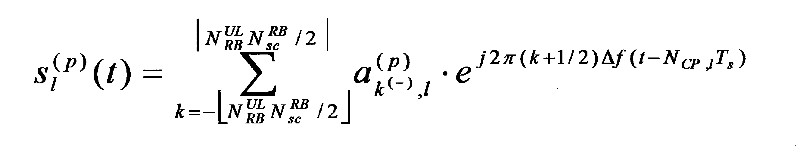
ここで、s(p)
l(t)は、アンテナポートpにおける、SC-FDMAシンボルlに対応するコンテンツに基づき生成される、SC-FDMAシンボルlの時間tにおける時間連続信号である。また、NUL
RBは、上りリンク帯域のリソースブロック数であり、NRB
scは、リソースブロックのサブキャリア数であり、ceil()は、天井関数であり、floor()は床関数であり、a(p)
k
(-)
,lは、アンテナポートpにおける、リソースエレメント(k、l)のコンテンツであり、lはSC-FDMAシンボルのインデックスである。また、Δf=15kHzである。また、NCP,lは、SC-FDMAシンボルlのCP長である。また、Ts=1/(15000*2048)である。また、時間tは、0から(NCP,l+N)*Tsの間の範囲の値を備える。ここで、Tl,0は、SC-FDMAシンボルの送信タイミングである。例えば、Tl,0=0であってもよい。Nは2048である。eはネイピア数である。jは虚数単位である。πは円周率である。
Here, s (p) l (t) is a time continuous signal at time t of the SC-FDMA symbol l generated based on the content corresponding to the SC-FDMA symbol l at the antenna port p. N UL RB is the number of resource blocks in the uplink band, N RB sc is the number of subcarriers in the resource block, ceil () is a ceiling function, floor () is a floor function, a (p) k (-) , l is the content of the resource element (k, l) at the antenna port p, and l is the index of the SC-FDMA symbol. Further, Δf = 15 kHz. N CP, l is the CP length of the SC-FDMA symbol l. Also, T s = 1 / (15000 * 2048). The time t has a value in the range between 0 and (N CP, l + N) * T s . Here, T l, 0 is the transmission timing of the SC-FDMA symbol. For example, T l, 0 = 0. N is 2048. e is the number of Napiers. j is an imaginary unit. π is the circumference ratio.
ここで、天井関数とは、ある値を下回らない範囲で最小の整数を取得する関数であってもよい。また、床関数とは、ある値を上回らない範囲で最大の整数を取得する関数であってもよい。
Here, the ceiling function may be a function that obtains the smallest integer within a range that does not fall below a certain value. Further, the floor function may be a function that obtains the maximum integer within a range not exceeding a certain value.
例えば、部分シンボルは、時間連続信号s(p)
l (t)の少なくとも一部が0に設定されるシンボルであってもよい。ここで、時間連続信号の少なくとも一部が0に設定されることは、数式(4)に基づき与えられた値の少なくとも一部の時間連続信号が0であることを含まない。部分シンボルは、時間連続信号s(p)
l (t)の少なくとも一部が所定の数式に基づき与えられないことであってもよい。所定の数式は、数式(4)に示される数式であってもよい。
For example, the partial symbol may be a symbol in which at least a part of the time continuous signal s (p) l (t) is set to zero. Here, the fact that at least a part of the time continuous signal is set to 0 does not include that the time continuous signal of at least a part of the value given based on Equation (4) is 0. The partial symbol may be that at least a part of the time continuous signal s (p) l (t) is not given based on a predetermined mathematical expression. The predetermined mathematical formula may be a mathematical formula represented by the mathematical formula (4).
例えば、部分シンボルは、t=0からt=Tpartialの範囲において数式(4)に基づき時間連続信号s(p)
l (t)が与えられ、t= Tpartialからt=(NCP,l+N)*Tsの範囲において0が設定されることであってもよい。ここで、Tpartialは、ランダムアクセスプリアンブルのフォーマットごとに与えられてもよい。また、Tpartialは、ランダムアクセスプリアンブルのフォーマットごとに与えられてもよい。また、Tpartialは、上位層の信号に少なくとも基づき与えられてもよい。
For example, partial symbols, t = 0 t = T time based on Equation (4) in the region of partial continuous signal s (p) l (t) is given by, t = T partial from t = (N CP, l + N) * T s may be set to 0 in the range. Here, T partial may be given for each format of the random access preamble. T partial may be given for each format of the random access preamble. Also, T partial may be given based at least on the upper layer signal.
PUSCHの初期送信のためのSC-FDMAシンボル数NPUSCH-initial
symbは、第5の値に少なくとも基づき与えられてもよい。条件(A1)において、第5の値は、1、または、1以上であってもよい。また、条件(A2)において、第5の値は0であってもよい。また、条件(A3)において、第5の値は0であってもよい。
The SC-FDMA symbol number N PUSCH-initial symb for initial transmission of PUSCH may be given based at least on the fifth value. In the condition (A1), the fifth value may be 1 or 1 or more. In the condition (A2), the fifth value may be 0. In the condition (A3), the fifth value may be 0.
条件(A1)において、第5の値は、ランダムアクセスプリアンブルのフォーマットに少なくとも基づき与えられてもよい。例えば、条件(A1)において、第5の値は、ランダムアクセスプリアンブルのフォーマットごとに与えられてもよい。また、条件(A1)において、第5の値は、上位層の信号に少なくとも基づき与えられてもよい。
In the condition (A1), the fifth value may be given based at least on the format of the random access preamble. For example, in the condition (A1), the fifth value may be given for each format of the random access preamble. In the condition (A1), the fifth value may be given based at least on an upper layer signal.
条件(A1)において、第5の値は、ランダムアクセスプリアンブルのフォーマットの長さTPRACHに少なくとも基づき与えられてもよい。また、第5の値は、PUSCHの長さがランダムアクセスプリアンブルのフォーマットの長さと等しい、または、小さくなるように与えられてもよい。例えば、第5の値は、NPUSCH-initial
symb*Tsymb<TPRACHを満たす最大のNPUSCH-initial
symbとなるように設定されてもよい。
In the condition (A1), the fifth value may be given based at least on the format length T PRACH of the random access preamble. In addition, the fifth value may be given such that the length of the PUSCH is equal to or smaller than the length of the format of the random access preamble. For example, the fifth value may be set to be the largest N PUSCH-initial symb satisfying N PUSCH-initial symb * T symb <T PRACH.
PUSCHの初期送信のためのSC-FDMAシンボル数NPUSCH-initial
symbは、第5の値に加えて、第2の値NSRS、第3の値NPUSCH
start、第4の値NUL
symbに少なくとも基づき与えられてもよい。
SC-FDMA symbol number N PUSCH-initial symb for initial transmission of the PUSCH, in addition to the fifth value, the second value N SRS, third value N PUSCH start, the fourth value N UL symb It may be given based at least.
端末装置1が備える多重部1077による第2の系列のリソースエレメントへのマッピングの方法を説明する。ここで、第2の系列は、複素数値シンボルの系列であってもよい。第2の系列は、複素数値シンボルの離散フーリエ変換により与えられる系列であってもよい。複素数値シンボルの離散フーリエ変換により与えられる系列は、複素数値シンボルの系列とも称される。
A method of mapping to the second series of resource elements by the multiplexing unit 1077 included in the terminal device 1 will be described. Here, the second series may be a series of complex value symbols. The second sequence may be a sequence given by a discrete Fourier transform of a complex value symbol. A sequence given by a discrete Fourier transform of a complex value symbol is also referred to as a complex value symbol sequence.
条件(A1)が満たされない場合において、PUSCHの送信を指示する下りリンク制御情報に含まれる第1のフィールド(PUSCH ending symbol)が1を示す場合に、第2の系列はサブフレームの最後のSC-FDMAシンボルのリソースエレメントにマップされなくてもよい。ここで、第1のフィールドは、PUSCHの終了シンボルを示してもよい。また、条件(A1)が満たされないことは、条件(a1)から条件(a6)の一部または全部を少なくとも満たさないことであってもよい。PUSCHの終了シンボルは、PUSCHが送信されるサブフレームにおいて、PUSCHの送信が終了するSC-FDMAシンボルであってもよい。
When the condition (A1) is not satisfied, when the first field (PUSCH ending symbol) included in the downlink control information instructing transmission of PUSCH indicates 1, the second sequence is the last SC of the subframe. It does not have to be mapped to the resource element of the FDMA symbol. Here, the first field may indicate a PUSCH end symbol. Further, the condition (A1) not being satisfied may be that at least part or all of the conditions (a1) to (a6) are not satisfied. The PUSCH end symbol may be an SC-FDMA symbol in which the PUSCH transmission ends in a subframe in which the PUSCH is transmitted.
例えば、PUSCHの送信において、条件(a1)を満たさず、PUSCHの送信を指示する上りリンクグラントに含まれる第1のフィールド(PUSCH ending symbol)が1を示す場合に、第2の系列はサブフレームの最後のSC-FDMAシンボルのリソースエレメントにマップされなくてもよい。つまり、第1のステップ(700)以外においてPUSCHが送信され、PUSCHの送信を指示する上りリンクグラントに含まれるPUSCHの終了シンボルを示す第1のフィールド(PUSCH ending symbol)が1を示す場合に、第2の系列はサブフレームの最後のSC-FDMAシンボルのリソースエレメントにマップされなくてもよい。また、条件(a2)を満たさず、PUSCHの送信を指示する上りリンクグラントに含まれる第1のフィールド(PUSCH ending symbol)が1を示す場合に、第2の系列はサブフレームの最後のSC-FDMAシンボルのリソースエレメントにマップされなくてもよい。その他の条件に対しても同様であるため、説明を省略する。
For example, in the PUSCH transmission, when the first field (PUSCH ending symbol) included in the uplink grant instructing PUSCH transmission does not satisfy the condition (a1) and indicates 1, the second sequence is a subframe. May not be mapped to the resource element of the last SC-FDMA symbol. That is, when the PUSCH is transmitted in other than the first step (700) and the first field (PUSCH ending symbol) indicating the PUSCH end symbol included in the uplink grant instructing the PUSCH transmission indicates 1, The second sequence may not be mapped to the resource element of the last SC-FDMA symbol of the subframe. In addition, when the first field (PUSCH ending symbol) included in the uplink grant instructing PUSCH transmission indicates 1 without satisfying the condition (a2), the second sequence is the last SC− of the subframe. It does not have to be mapped to the resource element of the FDMA symbol. Since it is the same also about other conditions, description is abbreviate | omitted.
また、条件(A1)において、第2の系列はサブフレームの最後の1または1以上のNlast個のSC-FDMAシンボルのリソースエレメントにマップされなくてもよい。つまり、条件(A1)において、第2の系列はサブフレームの最後の1または1以上のNlast個のSC-FDMAシンボルのリソースエレメントにマップされなくてもよい。Nlastは第6の値Nlastとも称される。ここで、サブフレームの最後の1または1以上のNlast個のSC-FDMAシンボルのリソースエレメントにマップされないことは、サブフレームの最後のSC-FDMAシンボルから、サブフレームの最後からNlast個のSC-FDMAシンボルまでに含まれるSC-FDMAシンボルのリソースエレメントにマップされないことであってもよい。また、サブフレームの最後のSC-FDMAシンボルからサブフレームの最後からNlast番目のSC-FDMAシンボルまで、とは、サブフレームの最後のSC-FDMAシンボル、および、サブフレームの最後からNlast番目のSC-FDMAシンボルを含む。
In the condition (A1), the second sequence may not be mapped to the resource element of the last one or one or more N last SC-FDMA symbols in the subframe. That is, in the condition (A1), the second sequence may not be mapped to the resource element of the last one or more N last SC-FDMA symbols in the subframe. N last is also referred to as a sixth value N last . Here, the fact that it is not mapped to the resource element of the last one or more N last SC-FDMA symbols of the subframe means that from the last SC-FDMA symbol of the subframe, N last number of the last of the subframe It may not be mapped to the resource element of the SC-FDMA symbol included up to the SC-FDMA symbol. Further, since the last SC-FDMA symbol of the subframe from the last sub-frame to the N last th SC-FDMA symbol, and the last SC-FDMA symbol of the subframe, and, N last position from the last subframe Of SC-FDMA symbols.
また、PUSCHの送信において、第2の系列がマップされるリソースエレメントは、少なくともPUSCHのために割り当てられるリソースブロックに含まれるリソースエレメントである。PUSCHのために割り当てられるリソースブロックは、上りリンクグラント、または、設定された上りリンクグラントに基づき指示されてもよい。また、PUSCHのために割り当てられるリソースブロックは、仕様書等の記載等に基づき与えられてもよい。例えば、上りリンクグラントなしでPUSCHが送信される場合、PUSCHのために割り当てられる所定のリソースブロックは、あらかじめ割り当てられてもよい(または、仕様書の記載等に基づき与えられてもよい)。また、PUSCHのために割り当てられるリソースブロックは、システム情報に少なくとも基づき与えられてもよい。
In addition, in the PUSCH transmission, the resource element to which the second sequence is mapped is a resource element included in at least a resource block allocated for PUSCH. A resource block allocated for PUSCH may be indicated based on an uplink grant or a configured uplink grant. Moreover, the resource block allocated for PUSCH may be given based on description of a specification etc. For example, when a PUSCH is transmitted without an uplink grant, a predetermined resource block assigned for the PUSCH may be assigned in advance (or may be given based on the description of the specification or the like). Moreover, the resource block allocated for PUSCH may be given based at least on the system information.
また、第2の系列は、参照信号の送信のために用いられるリソースエレメントにマップされない。
Also, the second sequence is not mapped to the resource element used for transmitting the reference signal.
また、PUSCHが送信されるサービングセルのサブフレームにおいてSRSが送信される場合に、第2の系列はサブフレームの最後のSC-FDMAシンボルのリソースエレメントにマップされない。
Also, when SRS is transmitted in the subframe of the serving cell in which PUSCH is transmitted, the second sequence is not mapped to the resource element of the last SC-FDMA symbol of the subframe.
また、PUSCHのための帯域(リソース)の少なくとも一部がセル固有SRSのサブフレームと重複し、かつ、端末装置1が所定の動作モードに設定されている場合に、第2の系列はサブフレームの最後のSC-FDMAシンボルのリソースエレメントにマップされない。ここで、所定の動作モードは、non-BL/CEのモード、または、CEModeAが設定されるBL/CEのモードであってもよい。ここで、non-BL-CEとは、BL/CE(Bandwidth reduced Low complexity / Coverage Enhancement)のモードではないことである。BL/CEのモードは、機械向け通信(MTC: Machine Type Communication)をサポートするモードであってもよい。CE Mode Aは、機械向け通信のための第1のモードである。
Further, when at least a part of a band (resource) for PUSCH overlaps with a cell-specific SRS subframe and the terminal apparatus 1 is set to a predetermined operation mode, the second sequence is a subframe. Is not mapped to the resource element of the last SC-FDMA symbol. Here, the predetermined operation mode may be a non-BL / CE mode or a BL / CE mode in which CEModeA is set. Here, non-BL-CE means that the mode is not BL / CE (Bandwidth reduced Low complexity / Coverage Enhancement). The BL / CE mode may be a mode that supports machine-oriented communication (MTC: “Machine” Type “Communication”). CE Mode A is the first mode for machine communication.
また、第2の系列は、PUSCHが送信されるサービングセルのサブフレームにおいて第1のUE固有SRSが設定されるSC-FDMAシンボルのリソースエレメントにマップされない。
In addition, the second sequence is not mapped to the resource element of the SC-FDMA symbol in which the first UE-specific SRS is set in the subframe of the serving cell in which the PUSCH is transmitted.
また、端末装置1が複数のタイミングアドバンスグループ(TAG)を設定される場合に、第2の系列は、PUSCHが送信されるセルのサブフレームにおいて第2のUE固有SRSが設定されるSC-FDMAシンボルのリソースエレメントにマップされない。
Further, when the terminal apparatus 1 is set with a plurality of timing advance groups (TAGs), the second sequence is SC-FDMA in which the second UE-specific SRS is set in the subframe of the cell in which the PUSCH is transmitted. Not mapped to the symbol's resource element.
また、下りリンク制御情報に含まれ、PUSCHの送信開始シンボルを指示する第2のフィールド(PUSCH starting position)が01、10、または、11を示す場合に、第2の系列はサブフレームの最初のSC-FDMAシンボルのリソースエレメントにマップされない。ここで、PUSCHの送信開始シンボルとは、PUSCHが送信されるサブフレームにおいて、送信が開始されるSC-FDMAシンボルであってもよい。
In addition, when the second field (PUSCH starting 含 ま position) included in the downlink control information and indicating the PUSCH transmission start symbol indicates 01, 10, or 11, the second sequence is the first subframe. Not mapped to resource element of SC-FDMA symbol. Here, the PUSCH transmission start symbol may be an SC-FDMA symbol in which transmission is started in a subframe in which the PUSCH is transmitted.
また、第6の値Nlastは、ランダムアクセスプリアンブルのフォーマットに少なくとも基づき与えられてもよい。例えば、第6の値Nlastは、ランダムアクセスプリアンブルのフォーマットごとに与えられてもよい。また、第6の値Nlastは、上位層の信号に少なくとも基づき与えられてもよい。
The sixth value N last may be given based at least on the format of the random access preamble. For example, the sixth value N last may be given for each format of the random access preamble. Further, the sixth value N last may be given based at least on the upper layer signal.
また、第6の値Nlastは、ランダムアクセスプリアンブルのフォーマットの長さTPRACHに少なくとも基づき与えられてもよい。また、第6の値Nlastは、PUSCH送信の長さがランダムアクセスプリアンブルのフォーマットの長さと等しい、または、小さくなるように与えられてもよい。例えば、第6の値Nlastは、NPUSCH-initial
symb*Tsymb<TPRACHを満たす最大のNPUSCH-initial
symbとなるように設定されてもよい。ここで、Tsymbは、PUSCH送信のためのSC-FDMAシンボルの長さである。
The sixth value N last may be given based at least on the format length T PRACH of the random access preamble. Further, the sixth value N last may be given such that the length of PUSCH transmission is equal to or smaller than the length of the format of the random access preamble. For example, the sixth value N last may be set to be the maximum N PUSCH-initial symb that satisfies N PUSCH-initial symb * T symb <T PRACH . Here, T symb is the length of the SC-FDMA symbols for PUSCH transmission.
第2の系列が所定のリソースエレメントにマップされないことは、第2の系列が、PUSCHの送信のために割り当てられるリソースブロックに含まれるリソースエレメントのうち、所定のリソースエレメントにマップされないことであってもよい。
The fact that the second sequence is not mapped to a predetermined resource element means that the second sequence is not mapped to a predetermined resource element among resource elements included in resource blocks allocated for PUSCH transmission. Also good.
例えば、条件(A1)が満たされない場合において、PUSCHの送信を指示する上りリンクグラントに含まれる第1のフィールド(PUSCH ending symbol)が1を示す場合に、第2の系列は、PUSCHの送信のために割り当てられるリソースブロックに含まれるリソースエレメントのうち、サブフレームの最後のSC-FDMAシンボルのリソースエレメントにマップされなくてもよい。
For example, when the condition (A1) is not satisfied and the first field (PUSCH ending symbol) included in the uplink grant instructing PUSCH transmission indicates 1, the second sequence is the PUSCH transmission Therefore, among the resource elements included in the resource block allocated for this purpose, it may not be mapped to the resource element of the last SC-FDMA symbol of the subframe.
また、条件(A1)において、第2の系列は、PUSCHの送信のために割り当てられるリソースブロックに含まれるリソースエレメントのうち、サブフレームの最後の1または1以上のNlast個のSC-FDMAシンボルのリソースエレメントにマップされなくてもよい。
In the condition (A1), the second sequence includes N last SC-FDMA symbols of the last one or one or more of the subframes among the resource elements included in the resource block allocated for PUSCH transmission. Need not be mapped to any resource element.
また、第2の系列が所定のリソースエレメントにマップされないことは、PUSCHの送信のために割り当てられるリソースブロックに含まれるリソースエレメントのうち、所定のリソースエレメント以外に、第2の系列がマップされることであってもよい。
In addition, the fact that the second sequence is not mapped to the predetermined resource element means that the second sequence is mapped in addition to the predetermined resource element among the resource elements included in the resource block allocated for PUSCH transmission. It may be.
例えば、条件(A1)が満たされない場合において、PUSCHの送信を指示する下りリンク制御情報に含まれる第1のフィールド(PUSCH ending symbol)が1を示す場合に、第2の系列は、PUSCHの送信のために割り当てられるリソースブロックに含まれるリソースエレメントのうち、サブフレームの最後のSC-FDMAシンボルのリソースエレメント以外にマップされてもよい。
For example, when the condition (A1) is not satisfied, when the first field (PUSCH ending symbol) included in the downlink control information instructing PUSCH transmission indicates 1, the second sequence is PUSCH transmission. Among the resource elements included in the resource block allocated for the subframe, the resource element may be mapped to other than the resource element of the last SC-FDMA symbol of the subframe.
また、条件(A1)において、第2の系列は、PUSCHの送信のために割り当てられるリソースブロックに含まれるリソースエレメントのうち、サブフレームの最後の1または1以上のNlast個のSC-FDMAシンボルのリソースエレメント以外にマップされてもよい。
In the condition (A1), the second sequence includes N last SC-FDMA symbols of the last one or one or more of the subframes among the resource elements included in the resource block allocated for PUSCH transmission. It may be mapped to other than the resource elements.
また、第2の系列が所定のリソースエレメントにマップされないことは、第2の系列がマップされるリソースエレメントに所定のリソースエレメントが含まれないことであってもよい。
Also, the fact that the second sequence is not mapped to a predetermined resource element may mean that the predetermined resource element is not included in the resource element to which the second sequence is mapped.
例えば、条件(A1)が満たされない場合において、PUSCHの送信を指示する下りリンク制御情報に含まれる第1のフィールド(PUSCH ending symbol)が1を示す場合に、第2の系列がマップされるリソースエレメントに、サブフレームの最後のSC-FDMAシンボルのリソースエレメントが含まれなくてもよい。
For example, when the condition (A1) is not satisfied and the first field (PUSCH ending マ ッ プ symbol) included in the downlink control information instructing PUSCH transmission indicates 1, the resource to which the second sequence is mapped The element may not include the resource element of the last SC-FDMA symbol of the subframe.
また、条件(A1)において、第2の系列がマップされるリソースエレメントに、サブフレームの最後の1または1以上のNlast個のSC-FDMAシンボルのリソースエレメントが含まれなくてもよい。
Further, in the condition (A1), the resource element to which the second sequence is mapped may not include the resource element of the last one or one or more N last SC-FDMA symbols in the subframe.
以下、本実施形態における、端末装置1の種々の態様について説明する。
Hereinafter, various aspects of the terminal device 1 in the present embodiment will be described.
(1)上記の目的を達成するために、本発明の態様は、以下のような手段を講じた。すなわち、本発明の第1の態様は、端末装置1であって、複素数値シンボルを、1つのサブフレームにおけるリソースエレメントにマップするリソースマップ部と、前記複素数値シンボルを含むPUSCHを所定のサブフレームで送信する送信部と、を備え、前記PUSCHの送信が2ステップコンテンションベースランダムアクセス手順における前記PUSCHの送信である場合に、前記複素数値シンボルは前記所定のサブフレームの最後の1または1以上の所定のSC-FDMAシンボルの前記リソースエレメントにマップされず、前記PUSCHの送信が前記2ステップコンテンションベースランダムアクセス手順における前記PUSCHの送信ではなく、かつ、前記PUSCHの送信を指示する下りリンク制御情報に含まれる第1のフィールド(PUSCH ending symbol)が1を示す場合に、前記複素数値シンボルは前記所定のサブフレームの最後のSC-FDMAシンボルの前記リソースエレメントにマップされず、前記複素数値シンボルがマップされる前記リソースエレメントは少なくとも前記PUSCHのために割り当てられるリソースブロックに含まれる前記リソースブロックである。
(1) In order to achieve the above object, the aspect of the present invention takes the following measures. That is, the first aspect of the present invention is a terminal apparatus 1, which is a resource map unit that maps complex value symbols to resource elements in one subframe, and a PUSCH that includes the complex value symbols in a predetermined subframe. And when the PUSCH transmission is a transmission of the PUSCH in a two-step contention-based random access procedure, the complex value symbol is the last one or more of the predetermined subframe. The downlink control is not mapped to the resource element of the predetermined SC-FDMA symbol, and the transmission of the PUSCH is not the transmission of the PUSCH in the two-step contention-based random access procedure, and directs the transmission of the PUSCH. The first included in the information When a field (PUSCH ending symbol) indicates 1, the complex value symbol is not mapped to the resource element of the last SC-FDMA symbol of the predetermined subframe, and the resource element to which the complex value symbol is mapped Is at least the resource block included in the resource block allocated for the PUSCH.
(2)また、本発明の第1の態様において、前記複素数値シンボルは参照信号の送信に用いられる前記リソースエレメントにマップされず、前記PUSCHが送信されるサービングセルの前記サブフレームにおいてSRSが送信される場合に、前記複素数値シンボルは前記サブフレームの最後のSC-FDMAシンボルのリソースエレメントにマップされず、前記PUSCHのための帯域(リソース)の少なくとも一部がセル固有SRSの前記サブフレームと重複し、かつ、前記端末装置1が所定の動作モードに設定されている場合に、前記複素数値シンボルは前記サブフレームの最後の前記SC-FDMAシンボルの前記リソースエレメントにマップされず、前記複素数値シンボルは前記PUSCHが送信される前記サブフレームにおいて第1の固有SRSが設定される前記SC-FDMAシンボルの前記リソースエレメントにマップされず、前記端末装置1が複数のタイミングアドバンスグループを設定される場合に、前記複素数値シンボルは前記PUSCHが送信される前記サブフレームにおいて第2の固有SRSが設定される前記SC-FDMAシンボルの前記リソースエレメントにマップされず、前記下りリンク制御情報に含まれ、前記PUSCHの送信開始シンボルを指示する第2のフィールド(PUSCH starting position)が01、10、または、11を示す場合に、前記複素数値シンボルは前記サブフレームの最初の前記SC-FDMAシンボルの前記リソースエレメントにマップされない。
(2) Also, in the first aspect of the present invention, the complex value symbol is not mapped to the resource element used for transmitting a reference signal, and an SRS is transmitted in the subframe of the serving cell in which the PUSCH is transmitted. The complex value symbol is not mapped to the resource element of the last SC-FDMA symbol of the subframe, and at least a part of the band (resource) for the PUSCH overlaps the subframe of the cell-specific SRS. When the terminal device 1 is set to a predetermined operation mode, the complex value symbol is not mapped to the resource element of the last SC-FDMA symbol of the subframe, and the complex value symbol In the subframe in which the PUSCH is transmitted When the terminal device 1 is set with a plurality of timing advance groups without being mapped to the resource element of the SC-FDMA symbol in which the first unique SRS is set, the PUSCH is transmitted as the complex value symbol. A second field that is not mapped to the resource element of the SC-FDMA symbol in which a second unique SRS is set in the subframe and that is included in the downlink control information and indicates a transmission start symbol of the PUSCH When (PUSCH starting position) indicates 01, 10, or 11, the complex value symbol is not mapped to the resource element of the first SC-FDMA symbol of the subframe.
(3)また、本発明の第1の態様において、前記PUSCHの送信が前記2ステップコンテンションベースランダムアクセス手順における前記PUSCHの送信である場合に、前記所定のSC-FDMAシンボルは、ランダムアクセスプリアンブルのフォーマットに少なくとも基づき与えられる。
(3) Also, in the first aspect of the present invention, when the PUSCH transmission is the PUSCH transmission in the two-step contention-based random access procedure, the predetermined SC-FDMA symbol is a random access preamble. Given at least based on the format.
(4)また、本発明の第1の態様において、前記PUSCHの送信が前記2ステップコンテンションベースランダムアクセス手順における前記PUSCHの送信である場合に、前記所定のSC-FDMAシンボルは、上位層の信号に少なくとも基づき与えられる。
(4) Also, in the first aspect of the present invention, when the PUSCH transmission is the PUSCH transmission in the two-step contention-based random access procedure, the predetermined SC-FDMA symbol is an upper layer Given at least based on the signal.
(5)また、本発明の第1の態様において、前記PUSCHの送信が前記2ステップコンテンションベースランダムアクセス手順における前記PUSCHの送信である場合に、前記PUSCHで送信されるサブフレームの最後のSC-FDMAシンボルの時間連続信号の少なくとも一部が0に設定され、前記時間連続信号が0に設定される期間は、少なくともランダムアクセスプリアンブルのフォーマットに基づき与えられる。
(5) Also, in the first aspect of the present invention, when the transmission of the PUSCH is the transmission of the PUSCH in the two-step contention-based random access procedure, the last SC of the subframe transmitted on the PUSCH A period in which at least part of the time continuous signal of the FDMA symbol is set to 0 and the time continuous signal is set to 0 is given based on at least the format of the random access preamble.
(6)また、本発明の第2の態様は、基地局装置3であって、PUSCHを受信する受信部と、前記PUSCHのリソースエレメントにマップされる複素数値シンボルを復調する復調部と、を備え、前記PUSCHの送信が2ステップコンテンションベースランダムアクセス手順における前記PUSCHの送信である場合に、前記複素数値シンボルは前記所定のサブフレームの最後の1または1以上の所定のSC-FDMAシンボルの前記リソースエレメントにマップされず、前記PUSCHの送信が前記2ステップコンテンションベースランダムアクセス手順における前記PUSCHの送信ではなく、かつ、前記PUSCHの送信を指示する下りリンク制御情報に含まれる第1のフィールド(PUSCH ending symbol)が1を示す場合に、前記複素数値シンボルは前記所定のサブフレームの最後のSC-FDMAシンボルの前記リソースエレメントにマップされず、第2の系列がマップされる前記リソースエレメントは少なくとも前記PUSCHのために割り当てられるリソースブロックに含まれる前記リソースブロックである。
(6) Moreover, the 2nd aspect of this invention is the base station apparatus 3, Comprising: The receiving part which receives PUSCH, The demodulation part which demodulates the complex value symbol mapped to the resource element of said PUSCH, And wherein the PUSCH transmission is the PUSCH transmission in a two-step contention based random access procedure, the complex value symbol is the last one or more predetermined SC-FDMA symbols of the predetermined subframe. The first field that is not mapped to the resource element, and that the transmission of the PUSCH is not the transmission of the PUSCH in the two-step contention-based random access procedure, and is included in the downlink control information that instructs the transmission of the PUSCH When (PUSCH ending symbol) is 1, The numerical symbol is not mapped to the resource element of the last SC-FDMA symbol of the predetermined subframe, and the resource element to which a second sequence is mapped is included in at least the resource block allocated for the PUSCH It is a resource block.
(7)また、本発明の第2の態様において、前記複素数値シンボルは参照信号の送信に用いられる前記リソースエレメントにマップされず、前記PUSCHが送信されるサービングセルの前記サブフレームにおいてSRSが送信される場合に、前記複素数値シンボルは前記サブフレームの最後のSC-FDMAシンボルのリソースエレメントにマップされず、前記PUSCHのための帯域(リソース)の少なくとも一部がセル固有SRSの前記サブフレームと重複し、かつ、前記PUSCHを送信する端末装置1が所定の動作モードに設定されている場合に、前記複素数値シンボルは前記サブフレームの最後の前記SC-FDMAシンボルの前記リソースエレメントにマップされず、前記複素数値シンボルは前記PUSCHが送信される前記サブフレームにおいて第1の固有SRSが設定される前記SC-FDMAシンボルの前記リソースエレメントにマップされず、前記端末装置1が複数のタイミングアドバンスグループを設定される場合に、前記複素数値シンボルは前記PUSCHが送信される前記サブフレームにおいて第2の固有SRSが設定される前記SC-FDMAシンボルの前記リソースエレメントにマップされず、前記下りリンク制御情報に含まれ、前記PUSCHの送信開始シンボルを指示する第2のフィールド(PUSCH starting position)が01、10、または、11を示す場合に、前記複素数値シンボルは前記サブフレームの最初の前記SC-FDMAシンボルの前記リソースエレメントにマップされない。
(7) Moreover, in the second aspect of the present invention, the complex value symbol is not mapped to the resource element used for transmission of a reference signal, and SRS is transmitted in the subframe of the serving cell in which the PUSCH is transmitted. The complex value symbol is not mapped to the resource element of the last SC-FDMA symbol of the subframe, and at least a part of the band (resource) for the PUSCH overlaps the subframe of the cell-specific SRS. And when the terminal apparatus 1 that transmits the PUSCH is set to a predetermined operation mode, the complex value symbol is not mapped to the resource element of the last SC-FDMA symbol of the subframe, The complex value symbol is transmitted before the PUSCH is transmitted. When the terminal device 1 is set with a plurality of timing advance groups without being mapped to the resource element of the SC-FDMA symbol in which a first unique SRS is set in a subframe, the complex value symbol is the PUSCH Is not mapped to the resource element of the SC-FDMA symbol in which a second specific SRS is set in the subframe in which is transmitted, and is included in the downlink control information, and indicates the PUSCH transmission start symbol. When the field of 2 (PUSCH starting position) indicates 01, 10, or 11, the complex value symbol is not mapped to the resource element of the first SC-FDMA symbol of the subframe.
(8)また、本発明の第2の態様において、前記PUSCHの送信が前記2ステップコンテンションベースランダムアクセス手順における前記PUSCHの送信である場合に、前記所定のSC-FDMAシンボルは、ランダムアクセスプリアンブルのフォーマットに少なくとも基づき与えられる。
(8) In addition, in the second aspect of the present invention, when the PUSCH transmission is the PUSCH transmission in the two-step contention-based random access procedure, the predetermined SC-FDMA symbol is a random access preamble. Given at least based on the format.
(9)また、本発明の第2の態様において、前記PUSCHの送信が前記2ステップコンテンションベースランダムアクセス手順における前記PUSCHの送信である場合に、前記所定のSC-FDMAシンボルは、上位層の信号に少なくとも基づき与えられる。
(9) Further, in the second aspect of the present invention, when the PUSCH transmission is the PUSCH transmission in the two-step contention-based random access procedure, the predetermined SC-FDMA symbol is an upper layer Given at least based on the signal.
(10)また、本発明の第2の態様において、前記PUSCHの送信が前記2ステップコンテンションベースランダムアクセス手順における前記PUSCHの送信である場合に、前記PUSCHで送信されるサブフレームの最後のSC-FDMAシンボルの時間連続信号の少なくとも一部が0に設定され、前記時間連続信号が0に設定される期間は、少なくともランダムアクセスプリアンブルのフォーマットに基づき与えられる。
(10) In addition, in the second aspect of the present invention, when the transmission of the PUSCH is the transmission of the PUSCH in the two-step contention-based random access procedure, the last SC of the subframe transmitted on the PUSCH A period in which at least part of the time continuous signal of the FDMA symbol is set to 0 and the time continuous signal is set to 0 is given based on at least the format of the random access preamble.
(11)また、本発明の第3の態様は、端末装置1であって、PUSCHの初期送信のために用いられるSC-FDMAシンボル数NPUSCH-initial
symbを決定する符号化部と、前記PUSCHを送信する送信部と、を備え、前記SC-FDMAシンボル数NPUSCH-initial
symbは、第1の値NPUSCH
endに少なくとも基づき与えられ、前記第1の値NPUSCH
endは、第1の条件において1、または1以上であり、第2の条件において1であり、第3の条件において0であり、前記第1の条件は、2ステップコンテンションベースランダムアクセス手順において前記PUSCHが送信されることであり、前記第2の条件は、前記PUSCHがLAAセルにおいて送信され、かつ、前記PUSCHがサブフレームの最後から2番目のSC-FDMAシンボルまで送信されることが設定され、かつ、前記PUSCHに対応する第2の値NSRSが0であることであり、前記第3の条件は、前記第1の条件、および、前記第2の条件とは異なる。
(11) The third aspect of the present invention is the terminal apparatus 1, wherein the coding unit determines the number of SC-FDMA symbols N PUSCH-initial symb used for initial transmission of PUSCH, and the PUSCH and a transmitter for transmitting the SC-FDMA symbol number N PUSCH-initial symb is given at least on the basis of the first value N PUSCH end the, the first value N PUSCH end the the first condition 1 or more, 1 in the second condition, 0 in the third condition, the first condition is that the PUSCH is transmitted in a two-step contention-based random access procedure The second condition is that the PUSCH is transmitted in an LAA cell and the PUSCH is transmitted from the last SC-FDMA symbol of the subframe. Rukoto is set and a second value N SRS corresponding to the PUSCH and that is 0, the third condition, the first condition, and, different from the second condition .
(12)また、本発明の第3の態様において、前記SC-FDMAシンボル数NPUSCH-initial
symbは、前記第1の値NPUSCH
endに加えて、前記第2の値NSRSに少なくとも基づき与えられ、前記第2の値NSRSは、所定の条件を満たす場合に1であり、前記所定の条件は第3の条件から第7の条件の一部または全部を少なくとも満たすことであり、前記第3の条件は、前記端末装置1に対して1つの上りリンクセル(ULセル)が設定され、かつ、前記PUSCHの初期送信とSRSの送信が同一のサブフレームに設定されることであり、前記第4の条件は、前記PUSCHの初期送信と前記SRSの送信が同一のサービングセルの前記サブフレームにおいて実施されることであり、前記第5の条件は、前記PUSCHの初期送信のための帯域(リソース、または周波数リソース)の少なくとも一部がセル固有SRSに設定される帯域と重複することであり、前記第6の条件は、前記PUSCHの初期送信のための前記サブフレームにおいて、第1のUE固有SRSが設定されることであり、前記第7の条件は、前記PUSCHの初期送信のための前記サブフレームにおいて、第2のUE固有SRSが設定され、かつ、前記端末装置1が複数のタイミングアドバンスグループを設定されることであり、前記第2の値NSRSは、前記所定の条件を満たさない場合に0である。
(12) In the third aspect of the present invention, the SC-FDMA symbol number N PUSCH-initial symb is given based on at least the second value N SRS in addition to the first value N PUSCH end. The second value N SRS is 1 when a predetermined condition is satisfied, and the predetermined condition is that at least a part or all of the third condition to the seventh condition is satisfied; The condition of 3 is that one uplink cell (UL cell) is set for the terminal device 1 and the initial transmission of the PUSCH and the transmission of the SRS are set in the same subframe, The fourth condition is that the initial transmission of the PUSCH and the transmission of the SRS are performed in the subframe of the same serving cell, and the fifth condition is a band (resource) for the initial transmission of the PUSCH. Or at least a part of the frequency resource) overlaps with the band set in the cell-specific SRS, and the sixth condition is the first UE-specific SRS in the subframe for the initial transmission of the PUSCH. The seventh condition is that a second UE-specific SRS is set in the subframe for initial transmission of the PUSCH, and the terminal device 1 has a plurality of timing advance groups. Is set, and the second value N SRS is 0 when the predetermined condition is not satisfied.
(13)また、本発明の第3の態様において、前記SC-FDMAシンボル数NPUSCH-initial
symbは、前記第1の値NPUSCH
endと前記第2の値NSRSに加えて、第3の値NPUSCH
startに少なくとも基づき与えられ、前記第3の値NPUSCH
startは、前記PUSCHの送信がLAAセルにおいて設定され、かつ、前記PUSCHの送信が最初のSC-FDMAシンボルの先頭から開始されないことが指示された場合に1であり、それ以外の場合に0である。
(13) In addition, in the third aspect of the present invention, the number of SC-FDMA symbols N PUSCH-initial symb includes a third value in addition to the first value N PUSCH end and the second value N SRS . Is given based at least on the value N PUSCH start , the third value N PUSCH start is that the PUSCH transmission is set in the LAA cell and the PUSCH transmission does not start from the beginning of the first SC-FDMA symbol Is 1 when instructed, and 0 otherwise.
(14)また、本発明の第3の態様において、前記第1の条件において、前記第1の値NPUSCH
endは、ランダムアクセスプリアンブルのフォーマットに少なくとも基づき与えられる。
(14) Further, in the third aspect of the present invention, in the first condition, the first value N PUSCH end is given based at least on a format of a random access preamble.
(15)また、本発明の第3の態様において、前記第1の条件において、前記第1の値NPUSCH
endは、上位層の信号に少なくとも基づき与えられる。
(15) In the third aspect of the present invention, in the first condition, the first value N PUSCH end is given based at least on an upper layer signal.
(16)また、本発明の第3の態様において、前記第1の条件において、前記PUSCHで送信されるサブフレームの最後のSC-FDMAシンボルの時間連続信号の少なくとも一部が0に設定され、前記時間連続信号が0に設定される期間は、少なくともランダムアクセスプリアンブルのフォーマットに基づき与えられる。
(16) Also, in the third aspect of the present invention, in the first condition, at least a part of a time continuous signal of the last SC-FDMA symbol of a subframe transmitted on the PUSCH is set to 0, The period in which the time continuous signal is set to 0 is given based on at least the format of the random access preamble.
(17)また、本発明の第4の態様は、基地局装置3であって、PUSCHの初期送信のために用いられるSC-FDMAシンボル数NPUSCH-initial
symbを決定する復号化部と、前記PUSCHを受信する送信部と、を備え、前記SC-FDMAシンボル数NPUSCH-initial
symbは、第1の値NPUSCH
endに少なくとも基づき与えられ、前記第1の値NPUSCH
endは、第1の条件において1、または1以上であり、第2の条件において1であり、第3の条件において0であり、前記第1の条件は、2ステップコンテンションベースランダムアクセス手順において前記PUSCHが送信されることであり、前記第2の条件は、前記PUSCHがLAAセルにおいて送信され、かつ、前記PUSCHがサブフレームの最後から2番目のSC-FDMAシンボルまで送信されることが設定され、かつ、前記PUSCHに対応する第2の値NSRSが0であることであり、前記第3の条件は、前記第1の条件、および、前記第2の条件とは異なる。
(17) Further, a fourth aspect of the present invention is the base station apparatus 3, wherein the decoding unit for determining the SC-FDMA symbol number N PUSCH-initial symb used for the initial transmission of PUSCH ; comprising a transmitting unit for receiving the PUSCH, the, the SC-FDMA symbol number N PUSCH-initial symb is given at least on the basis of the first value N PUSCH end the, the first value N PUSCH end the the first 1 or more in a condition, 1 in a second condition, 0 in a third condition, the PUSCH is transmitted in a two-step contention-based random access procedure The second condition is that the PUSCH is transmitted in the LAA cell, and the PUSCH is transmitted from the last SC-FDMA symbol of the subframe. It is set, and the second value N SRS corresponding to the PUSCH and that is 0, the third condition, the first condition, and, different from the second condition .
(18)また、本発明の第4の態様において、前記SC-FDMAシンボル数NPUSCH-initial
symbは、前記第1の値NPUSCH
endに加えて、前記第2の値NSRSに少なくとも基づき与えられ、前記第2の値NSRSは、所定の条件を満たす場合に1であり、前記所定の条件は第3の条件から第7の条件の一部または全部を少なくとも満たすことであり、前記第3の条件は、前記端末装置1に対して1つの上りリンクセル(ULセル)が設定され、かつ、前記PUSCHの初期送信とSRSの送信が同一のサブフレームに設定されることであり、前記第4の条件は、前記PUSCHの初期送信と前記SRSの送信が同一のサービングセルの前記サブフレームにおいて実施されることであり、前記第5の条件は、前記PUSCHの初期送信のための帯域(リソース、または周波数リソース)の少なくとも一部がセル固有SRSに設定される帯域と重複することであり、前記第6の条件は、前記PUSCHの初期送信のための前記サブフレームにおいて、第1のUE固有SRSが設定されることであり、前記第7の条件は、前記PUSCHの初期送信のための前記サブフレームにおいて、第2のUE固有SRSが設定され、かつ、前記端末装置1が複数のタイミングアドバンスグループを設定されることであり、前記第2の値NSRSは、前記所定の条件を満たさない場合に0である。
(18) In the fourth aspect of the present invention, the SC-FDMA symbol number N PUSCH-initial symb is given based at least on the second value N SRS in addition to the first value N PUSCH end. The second value N SRS is 1 when a predetermined condition is satisfied, and the predetermined condition is that at least a part or all of the third condition to the seventh condition is satisfied; The condition of 3 is that one uplink cell (UL cell) is set for the terminal device 1 and the initial transmission of the PUSCH and the transmission of the SRS are set in the same subframe, The fourth condition is that the initial transmission of the PUSCH and the transmission of the SRS are performed in the subframe of the same serving cell, and the fifth condition is a band (resource) for the initial transmission of the PUSCH. Or at least a part of the frequency resource) overlaps with the band set in the cell-specific SRS, and the sixth condition is the first UE-specific SRS in the subframe for the initial transmission of the PUSCH. The seventh condition is that a second UE-specific SRS is set in the subframe for initial transmission of the PUSCH, and the terminal device 1 has a plurality of timing advance groups. Is set, and the second value N SRS is 0 when the predetermined condition is not satisfied.
(19)また、本発明の第4の態様において、前記SC-FDMAシンボル数NPUSCH-initial
symbは、前記第1の値NPUSCH
endと前記第2の値NSRSに加えて、第3の値NPUSCH
startに少なくとも基づき与えられ、前記第3の値NPUSCH
startは、前記PUSCHの送信がLAAセルにおいて設定され、かつ、前記PUSCHの送信が最初のSC-FDMAシンボルの先頭から開始されないことが指示された場合に1であり、それ以外の場合に0である。
(19) In addition, in the fourth aspect of the present invention, the SC-FDMA symbol number N PUSCH-initial symb includes a third value in addition to the first value N PUSCH end and the second value N SRS . Is given based at least on the value N PUSCH start , the third value N PUSCH start is that the PUSCH transmission is set in the LAA cell and the PUSCH transmission does not start from the beginning of the first SC-FDMA symbol Is 1 when instructed, and 0 otherwise.
(20)また、本発明の第4の態様において、前記第1の条件において、前記第1の値NPUSCH
endは、ランダムアクセスプリアンブルのフォーマットに少なくとも基づき与えられる。
(20) In the fourth aspect of the present invention, in the first condition, said first value N PUSCH end The is given at least on the basis of the format of the random access preamble.
(21)また、本発明の第4の態様において、前記第1の条件において、前記第1の値NPUSCH
endは、上位層の信号に少なくとも基づき与えられる。
(21) Further, in the fourth aspect of the present invention, in the first condition, the first value N PUSCH end is given based at least on an upper layer signal.
(22)また、本発明の第4の態様において、前記第1の条件において、前記PUSCHで送信されるサブフレームの最後のSC-FDMAシンボルの時間連続信号の少なくとも一部が0に設定され、前記時間連続信号が0に設定される期間は、少なくともランダムアクセスプリアンブルのフォーマットに基づき与えられる。
(22) Further, in the fourth aspect of the present invention, in the first condition, at least a part of a time continuous signal of the last SC-FDMA symbol of a subframe transmitted on the PUSCH is set to 0, The period in which the time continuous signal is set to 0 is given based on at least the format of the random access preamble.
これにより、端末装置および基地局装置が互いに、効率的にランダムアクセス手順を実行することができる。
Thereby, the terminal device and the base station device can efficiently execute the random access procedure with each other.
本発明の一態様に関わる基地局装置3は、複数の装置から構成される集合体(装置グループ)として実現することもできる。装置グループを構成する装置の各々は、上述した実施形態に関わる基地局装置3の各機能または各機能ブロックの一部、または、全部を備えてもよい。装置グループとして、基地局装置3の一通りの各機能または各機能ブロックを有していればよい。また、上述した実施形態に関わる端末装置1は、集合体としての基地局装置と通信することも可能である。
The base station device 3 according to one aspect of the present invention can be realized as an aggregate (device group) composed of a plurality of devices. Each of the devices constituting the device group may include a part or all of each function or each functional block of the base station device 3 according to the above-described embodiment. The device group only needs to have one function or each function block of the base station device 3. The terminal device 1 according to the above-described embodiment can also communicate with the base station device as an aggregate.
また、上述した実施形態における基地局装置3は、EUTRAN(Evolved Universal Terrestrial Radio Access Network)であってもよい。また、上述した実施形態における基地局装置3は、eNodeBに対する上位ノードの機能の一部または全部を有してもよい。
Further, the base station apparatus 3 in the above-described embodiment may be EUTRAN (Evolved Universal Terrestrial Radio Access Network). In addition, the base station device 3 in the above-described embodiment may have a part or all of the functions of the upper node for the eNodeB.
本発明の一態様に関わる装置で動作するプログラムは、本発明の一態様に関わる上述した実施形態の機能を実現するように、Central Processing Unit(CPU)等を制御してコンピュータを機能させるプログラムであっても良い。プログラムあるいはプログラムによって取り扱われる情報は、処理時に一時的にRandom Access Memory(RAM)などの揮発性メモリに読み込まれ、あるいはフラッシュメモリなどの不揮発性メモリやHard Disk Drive(HDD)に格納され、必要に応じてCPUによって読み出し、修正・書き込みが行なわれる。
A program that operates in a device according to one aspect of the present invention is a program that controls a central processing unit (CPU) or the like to function a computer so as to realize the functions of the above-described embodiments according to one aspect of the present invention. There may be. The program or the information handled by the program is temporarily read into volatile memory such as Random Access Memory (RAM) during processing, or stored in nonvolatile memory such as flash memory or Hard Disk Drive (HDD). In response, the CPU reads and corrects / writes.
尚、上述した実施形態における装置の一部、をコンピュータで実現するようにしても良い。その場合、この制御機能を実現するためのプログラムをコンピュータが読み取り可能な記録媒体に記録して、この記録媒体に記録されたプログラムをコンピュータシステムに読み込ませ、実行することによって実現してもよい。ここでいう「コンピュータシステム」とは、装置に内蔵されたコンピュータシステムであって、オペレーティングシステムや周辺機器等のハードウェアを含むものとする。また、「コンピュータが読み取り可能な記録媒体」とは、半導体記録媒体、光記録媒体、磁気記録媒体等のいずれであってもよい。
In addition, you may make it implement | achieve a part of apparatus in embodiment mentioned above with a computer. In that case, the program for realizing the control function may be recorded on a computer-readable recording medium, and the program recorded on the recording medium may be read by the computer system and executed. The “computer system” here is a computer system built in the apparatus, and includes hardware such as an operating system and peripheral devices. The “computer-readable recording medium” may be any of a semiconductor recording medium, an optical recording medium, a magnetic recording medium, and the like.
さらに「コンピュータが読み取り可能な記録媒体」とは、インターネット等のネットワークや電話回線等の通信回線を介してプログラムを送信する場合の通信線のように、短時間、動的にプログラムを保持するもの、その場合のサーバやクライアントとなるコンピュータシステム内部の揮発性メモリのように、一定時間プログラムを保持しているものも含んでもよい。また上記プログラムは、前述した機能の一部を実現するためのものであってもよく、さらに前述した機能をコンピュータシステムにすでに記録されているプログラムとの組み合わせで実現できるものであってもよい。
“Computer-readable recording medium” means a program that dynamically holds a program for a short time, such as a communication line when transmitting a program via a network such as the Internet or a communication line such as a telephone line. In this case, a volatile memory inside a computer system that serves as a server or a client may also include a program that holds a program for a certain period of time. The program may be a program for realizing a part of the functions described above, and may be a program capable of realizing the functions described above in combination with a program already recorded in a computer system.
また、上述した実施形態に用いた装置の各機能ブロック、または諸特徴は、電気回路、すなわち典型的には集積回路あるいは複数の集積回路で実装または実行され得る。本明細書で述べられた機能を実行するように設計された電気回路は、汎用用途プロセッサ、デジタルシグナルプロセッサ(DSP)、特定用途向け集積回路(ASIC)、フィールドプログラマブルゲートアレイ(FPGA)、またはその他のプログラマブル論理デバイス、ディスクリートゲートまたはトランジスタロジック、ディスクリートハードウェア部品、またはこれらを組み合わせたものを含んでよい。汎用用途プロセッサは、マイクロプロセッサであってもよいし、代わりにプロセッサは従来型のプロセッサ、コントローラ、マイクロコントローラ、またはステートマシンであってもよい。汎用用途プロセッサ、または前述した各回路は、ディジタル回路で構成されていてもよいし、アナログ回路で構成されていてもよい。また、半導体技術の進歩により現在の集積回路に代替する集積回路化の技術が出現した場合、当該技術による集積回路を用いることも可能である。
Also, each functional block or various features of the apparatus used in the above-described embodiments can be implemented or executed by an electric circuit, that is, typically an integrated circuit or a plurality of integrated circuits. Electrical circuits designed to perform the functions described herein can be general purpose processors, digital signal processors (DSPs), application specific integrated circuits (ASICs), field programmable gate arrays (FPGAs), or others Programmable logic devices, discrete gate or transistor logic, discrete hardware components, or a combination thereof. A general purpose processor may be a microprocessor, but in the alternative, the processor may be any conventional processor, controller, microcontroller, or state machine. The general-purpose processor or each circuit described above may be configured by a digital circuit or an analog circuit. In addition, when an integrated circuit technology appears to replace the current integrated circuit due to the advancement of semiconductor technology, an integrated circuit based on the technology can be used.
なお、本願発明は上述の実施形態に限定されるものではない。実施形態では、装置の一例を記載したが、本願発明は、これに限定されるものではなく、屋内外に設置される据え置き型、または非可動型の電子機器、たとえば、AV機器、キッチン機器、掃除・洗濯機器、空調機器、オフィス機器、自動販売機、その他生活機器などの端末装置もしくは通信装置に適用出来る。
Note that the present invention is not limited to the above-described embodiment. In the embodiment, an example of the apparatus has been described. However, the present invention is not limited to this, and a stationary or non-movable electronic device installed indoors or outdoors, such as an AV device, a kitchen device, It can be applied to terminal devices or communication devices such as cleaning / washing equipment, air conditioning equipment, office equipment, vending machines, and other daily life equipment.
以上、この発明の実施形態に関して図面を参照して詳述してきたが、具体的な構成はこの実施形態に限られるものではなく、この発明の要旨を逸脱しない範囲の設計変更等も含まれる。また、本発明の一態様は、請求項に示した範囲で種々の変更が可能であり、異なる実施形態にそれぞれ開示された技術的手段を適宜組み合わせて得られる実施形態についても本発明の技術的範囲に含まれる。また、上記各実施形態に記載された要素であり、同様の効果を奏する要素同士を置換した構成も含まれる。
As described above, the embodiment of the present invention has been described in detail with reference to the drawings. However, the specific configuration is not limited to this embodiment, and includes design changes and the like without departing from the gist of the present invention. In addition, one aspect of the present invention can be modified in various ways within the scope of the claims, and the technical aspects of the present invention also relate to embodiments obtained by appropriately combining technical means disclosed in different embodiments. Included in the range. Moreover, it is the element described in each said embodiment, and the structure which substituted the element which has the same effect is also contained.
本発明の一態様は、例えば、通信システム、通信機器(例えば、携帯電話装置、基地局装置、無線LAN装置、或いはセンサーデバイス)、集積回路(例えば、通信チップ)、又はプログラム等において、利用することができる。
One embodiment of the present invention is used in, for example, a communication system, a communication device (for example, a mobile phone device, a base station device, a wireless LAN device, or a sensor device), an integrated circuit (for example, a communication chip), a program, or the like. be able to.
1(1A、1B、1C) 端末装置
3 基地局装置
101 上位層処理部
103 制御部
105 受信部
107 送信部
109 送受信アンテナ
1011 無線リソース制御部
1013 スケジューリング部
1051 復号化部
1053 復調部
1055 多重分離部
1057 無線受信部
1059 チャネル測定部
1071 符号化部
1073 PUSCH生成部
1075 PUCCH生成部
1077 多重部
1079 無線送信部
10711 上りリンク参照信号生成部
301 上位層処理部
303 制御部
305 受信部
307 送信部
309 送受信アンテナ
3011 無線リソース制御部
3013 スケジューリング部
3051 データ復調/復号部
3053 制御情報復調/復号部
3055 多重分離部
3057 無線受信部
3059 チャネル測定部
3071 符号化部
3073 変調部
3075 多重部
3077 無線送信部
3079 下りリンク参照信号生成部 1 (1A, 1B, 1C)Terminal apparatus 3 Base station apparatus 101 Upper layer processing section 103 Control section 105 Reception section 107 Transmission section 109 Transmission / reception antenna 1011 Radio resource control section 1013 Scheduling section 1051 Decoding section 1053 Demodulation section 1055 Demultiplexing section 1057 Radio reception unit 1059 Channel measurement unit 1071 Encoding unit 1073 PUSCH generation unit 1075 PUCCH generation unit 1077 Multiplexing unit 1079 Radio transmission unit 10711 Uplink reference signal generation unit 301 Upper layer processing unit 303 Control unit 305 Reception unit 307 Transmission unit 309 Transmission / reception Antenna 3011 Radio resource control unit 3013 Scheduling unit 3051 Data demodulation / decoding unit 3053 Control information demodulation / decoding unit 3055 Demultiplexing unit 3057 Radio reception unit 3059 Channel measurement unit 3071 Encoding unit 30 3 modulation section 3075 multiplexing section 3077 radio transmitting unit 3079 downlink reference signal generator
3 基地局装置
101 上位層処理部
103 制御部
105 受信部
107 送信部
109 送受信アンテナ
1011 無線リソース制御部
1013 スケジューリング部
1051 復号化部
1053 復調部
1055 多重分離部
1057 無線受信部
1059 チャネル測定部
1071 符号化部
1073 PUSCH生成部
1075 PUCCH生成部
1077 多重部
1079 無線送信部
10711 上りリンク参照信号生成部
301 上位層処理部
303 制御部
305 受信部
307 送信部
309 送受信アンテナ
3011 無線リソース制御部
3013 スケジューリング部
3051 データ復調/復号部
3053 制御情報復調/復号部
3055 多重分離部
3057 無線受信部
3059 チャネル測定部
3071 符号化部
3073 変調部
3075 多重部
3077 無線送信部
3079 下りリンク参照信号生成部 1 (1A, 1B, 1C)
Claims (12)
- 複素数値シンボルを、1つのサブフレームにおけるリソースエレメントにマップするリソースマップ部と、
前記複素数値シンボルを含むPUSCHを所定のサブフレームで送信する送信部と、を備え、
前記PUSCHの送信が2ステップコンテンションベースランダムアクセス手順における前記PUSCHの送信である場合に、前記複素数値シンボルは前記所定のサブフレームの最後の1または1以上の所定のSC-FDMAシンボルの前記リソースエレメントにマップされず、
前記PUSCHの送信が前記2ステップコンテンションベースランダムアクセス手順における前記PUSCHの送信ではなく、かつ、前記PUSCHの送信を指示する下りリンク制御情報に含まれる第1のフィールド(PUSCH ending symbol)が1を示す場合に、前記複素数値シンボルは前記所定のサブフレームの最後のSC-FDMAシンボルの前記リソースエレメントにマップされず、
前記複素数値シンボルがマップされる前記リソースエレメントは少なくとも前記PUSCHのために割り当てられるリソースブロックに含まれる前記リソースブロックである
端末装置。 A resource map portion that maps complex-valued symbols to resource elements in one subframe;
A transmitter that transmits the PUSCH including the complex value symbol in a predetermined subframe, and
When the transmission of the PUSCH is the transmission of the PUSCH in a two-step contention-based random access procedure, the complex value symbol is the resource of the last one or more predetermined SC-FDMA symbols of the predetermined subframe. Is not mapped to an element,
The transmission of the PUSCH is not the transmission of the PUSCH in the two-step contention-based random access procedure, and the first field (PUSCH ending symbol) included in the downlink control information instructing the transmission of the PUSCH is 1. The complex-valued symbol is not mapped to the resource element of the last SC-FDMA symbol of the given subframe,
The resource element to which the complex value symbol is mapped is at least the resource block included in a resource block allocated for the PUSCH. - 前記複素数値シンボルは参照信号の送信に用いられる前記リソースエレメントにマップされず、
前記PUSCHが送信されるサービングセルの前記サブフレームにおいてSRSが送信される場合に、前記複素数値シンボルは前記サブフレームの最後のSC-FDMAシンボルのリソースエレメントにマップされず、
前記PUSCHのための帯域(リソース)の少なくとも一部がセル固有SRSの前記サブフレームと重複し、かつ、前記端末装置が所定の動作モードに設定されている場合に、前記複素数値シンボルは前記サブフレームの最後の前記SC-FDMAシンボルの前記リソースエレメントにマップされず、
前記複素数値シンボルは前記PUSCHが送信される前記サブフレームにおいて第1の固有SRSが設定される前記SC-FDMAシンボルの前記リソースエレメントにマップされず、
前記端末装置が複数のタイミングアドバンスグループを設定される場合に、前記複素数値シンボルは前記PUSCHが送信される前記サブフレームにおいて第2の固有SRSが設定される前記SC-FDMAシンボルの前記リソースエレメントにマップされず、
前記下りリンク制御情報に含まれ、前記PUSCHの送信開始シンボルを指示する第2のフィールド(PUSCH starting position)が01、10、または、11を示す場合に、前記複素数値シンボルは前記サブフレームの最初の前記SC-FDMAシンボルの前記リソースエレメントにマップされない
請求項1に記載の端末装置。 The complex value symbol is not mapped to the resource element used for transmitting a reference signal,
When SRS is transmitted in the subframe of the serving cell in which the PUSCH is transmitted, the complex value symbol is not mapped to the resource element of the last SC-FDMA symbol in the subframe;
When at least a part of a band (resource) for the PUSCH overlaps with the subframe of cell-specific SRS and the terminal apparatus is set in a predetermined operation mode, the complex value symbol is the sub-frame. Not mapped to the resource element of the SC-FDMA symbol at the end of the frame;
The complex value symbol is not mapped to the resource element of the SC-FDMA symbol in which a first unique SRS is set in the subframe in which the PUSCH is transmitted,
When the terminal apparatus is set with a plurality of timing advance groups, the complex value symbol is set in the resource element of the SC-FDMA symbol in which a second specific SRS is set in the subframe in which the PUSCH is transmitted. Not mapped,
When the second field (PUSCH starting position) that is included in the downlink control information and indicates the PUSCH transmission start symbol indicates 01, 10, or 11, the complex value symbol is the first of the subframe. The terminal device according to claim 1, wherein the terminal device is not mapped to the resource element of the SC-FDMA symbol. - 前記PUSCHの送信が前記2ステップコンテンションベースランダムアクセス手順における前記PUSCHの送信である場合に、前記所定のSC-FDMAシンボルは、ランダムアクセスプリアンブルのフォーマットに少なくとも基づき与えられる
請求項2に記載の端末装置。 The terminal according to claim 2, wherein when the transmission of the PUSCH is the transmission of the PUSCH in the two-step contention-based random access procedure, the predetermined SC-FDMA symbol is provided based at least on a format of a random access preamble. apparatus. - 前記PUSCHの送信が前記2ステップコンテンションベースランダムアクセス手順における前記PUSCHの送信である場合に、前記所定のSC-FDMAシンボルは、上位層の信号に少なくとも基づき与えられる請求項2に記載の端末装置。 3. The terminal apparatus according to claim 2, wherein when the PUSCH transmission is the PUSCH transmission in the two-step contention-based random access procedure, the predetermined SC-FDMA symbol is provided based at least on a higher layer signal. .
- 前記PUSCHの送信が前記2ステップコンテンションベースランダムアクセス手順における前記PUSCHの送信である場合に、前記PUSCHで送信されるサブフレームの最後のSC-FDMAシンボルの時間連続信号の少なくとも一部が0に設定され、
前記時間連続信号が0に設定される期間は、少なくともランダムアクセスプリアンブルのフォーマットに基づき与えられる
請求項2に記載の端末装置。 When the transmission of the PUSCH is the transmission of the PUSCH in the two-step contention-based random access procedure, at least a part of the time continuous signal of the last SC-FDMA symbol of the subframe transmitted on the PUSCH is 0 Set,
The terminal apparatus according to claim 2, wherein the period in which the time continuous signal is set to 0 is given based on at least a format of a random access preamble. - PUSCHを受信する受信部と、
前記PUSCHのリソースエレメントにマップされる複素数値シンボルを復調する復調部と、を備え、
前記PUSCHの送信が2ステップコンテンションベースランダムアクセス手順における前記PUSCHの送信である場合に、前記複素数値シンボルは所定のサブフレームの最後の1または1以上の所定のSC-FDMAシンボルの前記リソースエレメントにマップされず、
前記PUSCHの送信が前記2ステップコンテンションベースランダムアクセス手順における前記PUSCHの送信ではなく、かつ、前記PUSCHの送信を指示する下りリンク制御情報に含まれる第1のフィールド(PUSCH ending symbol)が1を示す場合に、前記複素数値シンボルは前記所定のサブフレームの最後のSC-FDMAシンボルの前記リソースエレメントにマップされず、
第2の系列がマップされる前記リソースエレメントは少なくとも前記PUSCHのために割り当てられるリソースブロックに含まれる前記リソースブロックである
基地局装置。 A receiving unit for receiving PUSCH;
A demodulator that demodulates complex-valued symbols mapped to the resource elements of the PUSCH,
When the PUSCH transmission is the PUSCH transmission in a two-step contention-based random access procedure, the complex value symbol is the resource element of the last one or more predetermined SC-FDMA symbols of a predetermined subframe. Is not mapped to
The transmission of the PUSCH is not the transmission of the PUSCH in the two-step contention-based random access procedure, and the first field (PUSCH ending symbol) included in the downlink control information instructing the transmission of the PUSCH is 1. The complex-valued symbol is not mapped to the resource element of the last SC-FDMA symbol of the given subframe,
The resource element to which a second sequence is mapped is at least the resource block included in a resource block allocated for the PUSCH. - 前記複素数値シンボルは参照信号の送信に用いられる前記リソースエレメントにマップされず、
前記PUSCHが送信されるサービングセルの前記サブフレームにおいてSRSが送信される場合に、前記複素数値シンボルは前記サブフレームの最後のSC-FDMAシンボルのリソースエレメントにマップされず、
前記PUSCHのための帯域(リソース)の少なくとも一部がセル固有SRSの前記サブフレームと重複し、かつ、前記PUSCHを送信する端末装置が所定の動作モードに設定されている場合に、前記複素数値シンボルは前記サブフレームの最後の前記SC-FDMAシンボルの前記リソースエレメントにマップされず、
前記複素数値シンボルは前記PUSCHが送信される前記サブフレームにおいて第1の固有SRSが設定される前記SC-FDMAシンボルの前記リソースエレメントにマップされず、
前記端末装置が複数のタイミングアドバンスグループを設定される場合に、前記複素数値シンボルは前記PUSCHが送信される前記サブフレームにおいて第2の固有SRSが設定される前記SC-FDMAシンボルの前記リソースエレメントにマップされず、
前記下りリンク制御情報に含まれ、前記PUSCHの送信開始シンボルを指示する第2のフィールド(PUSCH starting position)が01、10、または、11を示す場合に、前記複素数値シンボルは前記サブフレームの最初の前記SC-FDMAシンボルの前記リソースエレメントにマップされない 請求項6に記載の基地局装置。 The complex value symbol is not mapped to the resource element used for transmitting a reference signal,
When SRS is transmitted in the subframe of the serving cell in which the PUSCH is transmitted, the complex value symbol is not mapped to the resource element of the last SC-FDMA symbol in the subframe;
When at least a part of a band (resource) for the PUSCH overlaps with the subframe of a cell-specific SRS and the terminal device that transmits the PUSCH is set to a predetermined operation mode, the complex value A symbol is not mapped to the resource element of the last SC-FDMA symbol of the subframe;
The complex value symbol is not mapped to the resource element of the SC-FDMA symbol in which a first unique SRS is set in the subframe in which the PUSCH is transmitted,
When the terminal apparatus is set with a plurality of timing advance groups, the complex value symbol is set in the resource element of the SC-FDMA symbol in which a second specific SRS is set in the subframe in which the PUSCH is transmitted. Not mapped,
When the second field (PUSCH starting position) that is included in the downlink control information and indicates the PUSCH transmission start symbol indicates 01, 10, or 11, the complex value symbol is the first of the subframe. The base station apparatus according to claim 6, wherein the base station apparatus is not mapped to the resource element of the SC-FDMA symbol. - 前記PUSCHの送信が前記2ステップコンテンションベースランダムアクセス手順における前記PUSCHの送信である場合に、前記所定のSC-FDMAシンボルは、ランダムアクセスプリアンブルのフォーマットに少なくとも基づき与えられる
請求項7に記載の基地局装置。 8. The base according to claim 7, wherein when the PUSCH transmission is the PUSCH transmission in the two-step contention-based random access procedure, the predetermined SC-FDMA symbol is provided based at least on a format of a random access preamble. Station equipment. - 前記PUSCHの送信が前記2ステップコンテンションベースランダムアクセス手順における前記PUSCHの送信である場合に、前記所定のSC-FDMAシンボルは、上位層の信号に少なくとも基づき与えられる
請求項7に記載の基地局装置。 The base station according to claim 7, wherein when the PUSCH transmission is the PUSCH transmission in the two-step contention-based random access procedure, the predetermined SC-FDMA symbol is given based at least on a higher layer signal. apparatus. - 前記PUSCHの送信が前記2ステップコンテンションベースランダムアクセス手順における前記PUSCHの送信である場合に、前記PUSCHで送信されるサブフレームの最後のSC-FDMAシンボルの時間連続信号の少なくとも一部が0に設定され、
前記時間連続信号が0に設定される期間は、少なくともランダムアクセスプリアンブルのフォーマットに基づき与えられる
請求項7に記載の基地局装置。 When the transmission of the PUSCH is the transmission of the PUSCH in the two-step contention-based random access procedure, at least a part of the time continuous signal of the last SC-FDMA symbol of the subframe transmitted on the PUSCH is 0 Set,
The base station apparatus according to claim 7, wherein the period in which the time continuous signal is set to 0 is given based on at least a format of a random access preamble. - 端末装置に用いられる通信方法であって、
複素数値シンボルを、1つのサブフレームにおけるリソースエレメントにマップするステップと、
前記複素数値シンボルを含むPUSCHを所定のサブフレームで送信するステップと、を備え、
前記PUSCHの送信が2ステップコンテンションベースランダムアクセス手順における前記PUSCHの送信である場合に、前記複素数値シンボルは前記所定のサブフレームの最後の1または1以上の所定のSC-FDMAシンボルの前記リソースエレメントにマップされず、
前記PUSCHの送信が前記2ステップコンテンションベースランダムアクセス手順における前記PUSCHの送信ではなく、かつ、前記PUSCHの送信を指示する下りリンク制御情報に含まれる第1のフィールド(PUSCH ending symbol)が1を示す場合に、前記複素数値シンボルは前記所定のサブフレームの最後のSC-FDMAシンボルの前記リソースエレメントにマップされず、
前記複素数値シンボルがマップされる前記リソースエレメントは少なくとも前記PUSCHのために割り当てられるリソースブロックに含まれる前記リソースブロックである
通信方法。 A communication method used for a terminal device,
Mapping complex-valued symbols to resource elements in one subframe;
Transmitting a PUSCH including the complex value symbol in a predetermined subframe, and
When the transmission of the PUSCH is the transmission of the PUSCH in a two-step contention-based random access procedure, the complex value symbol is the resource of the last one or more predetermined SC-FDMA symbols of the predetermined subframe. Is not mapped to an element,
The transmission of the PUSCH is not the transmission of the PUSCH in the two-step contention-based random access procedure, and the first field (PUSCH ending symbol) included in the downlink control information instructing the transmission of the PUSCH is 1. The complex-valued symbol is not mapped to the resource element of the last SC-FDMA symbol of the given subframe,
The communication method, wherein the resource element to which the complex value symbol is mapped is at least the resource block included in a resource block allocated for the PUSCH. - 基地局装置に用いられる通信方法であって、
PUSCHを受信するステップと、
前記PUSCHのリソースエレメントにマップされる複素数値シンボルを復調するステップと、を備え、
前記PUSCHの送信が2ステップコンテンションベースランダムアクセス手順における前記PUSCHの送信である場合に、前記複素数値シンボルは所定のサブフレームの最後の1または1以上の所定のSC-FDMAシンボルの前記リソースエレメントにマップされず、
前記PUSCHの送信が前記2ステップコンテンションベースランダムアクセス手順における前記PUSCHの送信ではなく、かつ、前記PUSCHの送信を指示する下りリンク制御情報に含まれる第1のフィールド(PUSCH ending symbol)が1を示す場合に、前記複素数値シンボルは前記所定のサブフレームの最後のSC-FDMAシンボルの前記リソースエレメントにマップされず、
第2の系列がマップされる前記リソースエレメントは少なくとも前記PUSCHのために割り当てられるリソースブロックに含まれる前記リソースブロックである
通信方法。 A communication method used in a base station device,
Receiving the PUSCH;
Demodulating complex-valued symbols mapped to resource elements of the PUSCH,
When the PUSCH transmission is the PUSCH transmission in a two-step contention-based random access procedure, the complex value symbol is the resource element of the last one or more predetermined SC-FDMA symbols of a predetermined subframe. Is not mapped to
The transmission of the PUSCH is not the transmission of the PUSCH in the two-step contention-based random access procedure, and the first field (PUSCH ending symbol) included in the downlink control information instructing the transmission of the PUSCH is 1. The complex-valued symbol is not mapped to the resource element of the last SC-FDMA symbol of the given subframe,
The communication method, wherein the resource element to which a second sequence is mapped is at least the resource block included in a resource block allocated for the PUSCH.
Priority Applications (3)
| Application Number | Priority Date | Filing Date | Title |
|---|---|---|---|
| CN201880007228.XA CN110249698A (en) | 2017-01-27 | 2018-01-26 | Terminal installation, base station apparatus and communication means |
| EP18745325.3A EP3576482A4 (en) | 2017-01-27 | 2018-01-26 | Terminal device, base station device, and communication method |
| US16/479,625 US20210337597A1 (en) | 2017-01-27 | 2018-01-26 | Terminal apparatus, base station apparatus, and communication method |
Applications Claiming Priority (2)
| Application Number | Priority Date | Filing Date | Title |
|---|---|---|---|
| JP2017-012884 | 2017-01-27 | ||
| JP2017012884A JP2020057822A (en) | 2017-01-27 | 2017-01-27 | Terminal device, base station device, and communication method |
Publications (1)
| Publication Number | Publication Date |
|---|---|
| WO2018139575A1 true WO2018139575A1 (en) | 2018-08-02 |
Family
ID=62978539
Family Applications (1)
| Application Number | Title | Priority Date | Filing Date |
|---|---|---|---|
| PCT/JP2018/002450 WO2018139575A1 (en) | 2017-01-27 | 2018-01-26 | Terminal device, base station device, and communication method |
Country Status (5)
| Country | Link |
|---|---|
| US (1) | US20210337597A1 (en) |
| EP (1) | EP3576482A4 (en) |
| JP (1) | JP2020057822A (en) |
| CN (1) | CN110249698A (en) |
| WO (1) | WO2018139575A1 (en) |
Cited By (14)
| Publication number | Priority date | Publication date | Assignee | Title |
|---|---|---|---|---|
| WO2020031819A1 (en) * | 2018-08-09 | 2020-02-13 | ソニー株式会社 | Wireless communication device, wireless communication method, and computer program |
| WO2020146831A1 (en) * | 2019-01-11 | 2020-07-16 | Qualcomm Incorporated | Timing indication for a two-step random access channel procedure |
| WO2020166104A1 (en) * | 2019-02-13 | 2020-08-20 | Kddi株式会社 | Terminal device for executing random access procedure, base station device, control method, and program |
| WO2020164623A1 (en) * | 2019-02-15 | 2020-08-20 | Telefonaktiebolaget Lm Ericsson (Publ) | Terminal device, network device and methods therein |
| CN111865388A (en) * | 2019-04-30 | 2020-10-30 | 华为技术有限公司 | Uplink beam management method and device |
| WO2021004375A1 (en) * | 2019-07-11 | 2021-01-14 | 维沃移动通信有限公司 | Edt data sending method and device |
| WO2021008558A1 (en) * | 2019-07-17 | 2021-01-21 | FG Innovation Company Limited | Method and apparatus for handling repetitions of physical uplink shared channel (pusch) transmission in wireless communication system |
| CN113424643A (en) * | 2019-02-13 | 2021-09-21 | 凯迪迪爱通信技术有限公司 | Terminal device, base station device, communication method, and program for performing two-step random access procedure |
| CN113728715A (en) * | 2019-02-13 | 2021-11-30 | Idac控股公司 | Method and apparatus for msg-A transmission in two-step RACH |
| JP2022506322A (en) * | 2018-11-01 | 2022-01-17 | ノキア テクノロジーズ オサケユイチア | Random access mode selection |
| JP2022510764A (en) * | 2018-09-28 | 2022-01-28 | 中▲興▼通▲訊▼股▲ふぇん▼有限公司 | Random access in wireless communication |
| JP2022520389A (en) * | 2019-02-14 | 2022-03-30 | 維沃移動通信有限公司 | Random access processing methods, devices, terminals, network devices and storage media |
| CN114340029A (en) * | 2018-10-31 | 2022-04-12 | 北京小米移动软件有限公司 | Method and device for transmitting random access indication information |
| EP3927085A4 (en) * | 2019-02-15 | 2022-08-31 | Ntt Docomo, Inc. | User terminal |
Families Citing this family (9)
| Publication number | Priority date | Publication date | Assignee | Title |
|---|---|---|---|---|
| US10568007B2 (en) | 2017-03-22 | 2020-02-18 | Comcast Cable Communications, Llc | Handover random access |
| US11057935B2 (en) | 2017-03-22 | 2021-07-06 | Comcast Cable Communications, Llc | Random access process in new radio |
| US11778657B2 (en) * | 2017-10-27 | 2023-10-03 | Apple Inc. | Control resource set information in physical broadcast channel |
| CN109842478A (en) * | 2017-11-26 | 2019-06-04 | 华为技术有限公司 | A kind of sequence determines method and apparatus |
| CN110167164A (en) * | 2018-02-14 | 2019-08-23 | 华为技术有限公司 | The method and communication equipment of random access resource configuration |
| EP3777437A1 (en) * | 2018-04-05 | 2021-02-17 | Nokia Technologies Oy | Transmission of a short contention resolution identifier |
| WO2020147071A1 (en) * | 2019-01-17 | 2020-07-23 | Zte Corporation | Transmitter-side processing of preambles and reference signals |
| CN112584496B (en) * | 2019-09-27 | 2023-06-30 | 维沃移动通信有限公司 | Resource using method and communication equipment |
| CN113260076A (en) * | 2020-02-13 | 2021-08-13 | 华硕电脑股份有限公司 | Method and apparatus for fallback action for small data transmission in wireless communication system |
Citations (1)
| Publication number | Priority date | Publication date | Assignee | Title |
|---|---|---|---|---|
| JP2017012884A (en) | 2016-10-25 | 2017-01-19 | 株式会社平和 | Game machine |
Family Cites Families (5)
| Publication number | Priority date | Publication date | Assignee | Title |
|---|---|---|---|---|
| AU2010250200B2 (en) * | 2009-05-21 | 2013-08-29 | Lg Electronics Inc. | Method and apparatus for transmitting reference signal in multi-antenna system |
| US8780878B2 (en) * | 2011-03-22 | 2014-07-15 | Innovative Sonic Corporation | Method and apparatus to improve aperiodic SRS (sounding reference symbol) in a wireless communication system |
| EP2945419B1 (en) * | 2013-01-09 | 2019-01-09 | LG Electronics Inc. | Method and user equipment for receiving signal and method and base station for transmitting signal |
| US20140286255A1 (en) * | 2013-03-25 | 2014-09-25 | Samsung Electronics Co., Ltd. | Uplink demodulation reference signals in advanced wireless communication systems |
| KR20160132368A (en) * | 2014-03-11 | 2016-11-18 | 엘지전자 주식회사 | Method for allocating temporary identifier to terminal in random access procedure in wireless communication system and apparatus tehrefor |
-
2017
- 2017-01-27 JP JP2017012884A patent/JP2020057822A/en active Pending
-
2018
- 2018-01-26 CN CN201880007228.XA patent/CN110249698A/en active Pending
- 2018-01-26 WO PCT/JP2018/002450 patent/WO2018139575A1/en unknown
- 2018-01-26 EP EP18745325.3A patent/EP3576482A4/en not_active Withdrawn
- 2018-01-26 US US16/479,625 patent/US20210337597A1/en not_active Abandoned
Patent Citations (1)
| Publication number | Priority date | Publication date | Assignee | Title |
|---|---|---|---|---|
| JP2017012884A (en) | 2016-10-25 | 2017-01-19 | 株式会社平和 | Game machine |
Non-Patent Citations (10)
| Title |
|---|
| "Motivation for new SI proposal: Enhancements to initial access and scheduling for low-latency LTE", RP-162295, 5 December 2016 (2016-12-05) |
| 3GPP TS 36.211, 6 January 2016 (2016-01-06) |
| 3GPP TS 36.212, 6 January 2016 (2016-01-06) |
| 3GPP TS 36.213, 6 January 2016 (2016-01-06) |
| 3GPP TS 36.321, 6 January 2016 (2016-01-06) |
| 3GPP TS 36.331, 7 January 2016 (2016-01-07) |
| ERICSSON: "NR two-step random access procedure", 3GPP TSG RAN WG1 NR ADHOC RL-1700300, 10 January 2017 (2017-01-10), XP051202779 * |
| LG ELECTRONICS: "Clarification of PUSCH rate matching with SRS", 3GPP TSG-RAN WG1#78B RL-144538, 11 October 2014 (2014-10-11), XP050885221 * |
| PANTECH: "Further consideration on Aperiodic SRS solutions", 3GPP TSG-RAN WG1#61 R1-102840, 4 May 2010 (2010-05-04), XP050419825 * |
| See also references of EP3576482A4 |
Cited By (26)
| Publication number | Priority date | Publication date | Assignee | Title |
|---|---|---|---|---|
| US11917681B2 (en) | 2018-08-09 | 2024-02-27 | Sony Corporation | Wireless communication device, wireless communication method, and computer program |
| WO2020031819A1 (en) * | 2018-08-09 | 2020-02-13 | ソニー株式会社 | Wireless communication device, wireless communication method, and computer program |
| JP7372317B2 (en) | 2018-09-28 | 2023-10-31 | 中興通訊股▲ふん▼有限公司 | Random access in wireless communication |
| JP2022510764A (en) * | 2018-09-28 | 2022-01-28 | 中▲興▼通▲訊▼股▲ふぇん▼有限公司 | Random access in wireless communication |
| US11924126B2 (en) | 2018-09-28 | 2024-03-05 | Zte Corporation | Random access in wireless communication |
| CN114340029B (en) * | 2018-10-31 | 2024-02-20 | 北京小米移动软件有限公司 | Method and device for transmitting random access indication information |
| CN114340029A (en) * | 2018-10-31 | 2022-04-12 | 北京小米移动软件有限公司 | Method and device for transmitting random access indication information |
| JP2022506322A (en) * | 2018-11-01 | 2022-01-17 | ノキア テクノロジーズ オサケユイチア | Random access mode selection |
| CN113424605B (en) * | 2019-01-11 | 2024-01-05 | 高通股份有限公司 | Timing indication for a two-step random access channel procedure |
| CN113424605A (en) * | 2019-01-11 | 2021-09-21 | 高通股份有限公司 | Timing indication for two-step random access channel procedure |
| WO2020146831A1 (en) * | 2019-01-11 | 2020-07-16 | Qualcomm Incorporated | Timing indication for a two-step random access channel procedure |
| US11438930B2 (en) | 2019-01-11 | 2022-09-06 | Qualcomm Incorporated | Timing indication for a two-step random access channel procedure |
| CN113728715A (en) * | 2019-02-13 | 2021-11-30 | Idac控股公司 | Method and apparatus for msg-A transmission in two-step RACH |
| CN113424644A (en) * | 2019-02-13 | 2021-09-21 | 凯迪迪爱通信技术有限公司 | Terminal device, base station device, control method, and program for performing random access procedure |
| WO2020166104A1 (en) * | 2019-02-13 | 2020-08-20 | Kddi株式会社 | Terminal device for executing random access procedure, base station device, control method, and program |
| JPWO2020166104A1 (en) * | 2019-02-13 | 2021-12-16 | Kddi株式会社 | Terminal equipment, base station equipment, control methods, and programs that perform random access procedures. |
| CN113424643A (en) * | 2019-02-13 | 2021-09-21 | 凯迪迪爱通信技术有限公司 | Terminal device, base station device, communication method, and program for performing two-step random access procedure |
| JP2022520389A (en) * | 2019-02-14 | 2022-03-30 | 維沃移動通信有限公司 | Random access processing methods, devices, terminals, network devices and storage media |
| JP7340615B2 (en) | 2019-02-14 | 2023-09-07 | 維沃移動通信有限公司 | Random access processing method, device, terminal, network equipment and storage medium |
| WO2020164623A1 (en) * | 2019-02-15 | 2020-08-20 | Telefonaktiebolaget Lm Ericsson (Publ) | Terminal device, network device and methods therein |
| EP3927085A4 (en) * | 2019-02-15 | 2022-08-31 | Ntt Docomo, Inc. | User terminal |
| CN111865388B (en) * | 2019-04-30 | 2022-04-05 | 华为技术有限公司 | Uplink beam management method and device |
| CN111865388A (en) * | 2019-04-30 | 2020-10-30 | 华为技术有限公司 | Uplink beam management method and device |
| WO2021004375A1 (en) * | 2019-07-11 | 2021-01-14 | 维沃移动通信有限公司 | Edt data sending method and device |
| WO2021008558A1 (en) * | 2019-07-17 | 2021-01-21 | FG Innovation Company Limited | Method and apparatus for handling repetitions of physical uplink shared channel (pusch) transmission in wireless communication system |
| US11224059B2 (en) | 2019-07-17 | 2022-01-11 | FG Innovation Company Limited | Method and apparatus for handling repetitions of physical uplink shared channel (PUSCH) transmission in wireless communication system |
Also Published As
| Publication number | Publication date |
|---|---|
| US20210337597A1 (en) | 2021-10-28 |
| CN110249698A (en) | 2019-09-17 |
| JP2020057822A (en) | 2020-04-09 |
| EP3576482A1 (en) | 2019-12-04 |
| EP3576482A4 (en) | 2020-09-09 |
Similar Documents
| Publication | Publication Date | Title |
|---|---|---|
| WO2018139575A1 (en) | Terminal device, base station device, and communication method | |
| JP7079583B2 (en) | Terminal device and communication method | |
| WO2018135631A1 (en) | Terminal device, base station device, communications method, and integrated circuit | |
| WO2018135640A1 (en) | Terminal device, base station device, communications method, and integrated circuit | |
| WO2018151230A1 (en) | Terminal device, base station device, communication method, and integrated circuit | |
| CN110192426B (en) | Terminal device, base station device, communication method, and integrated circuit | |
| JP5856810B2 (en) | Base station apparatus, mobile station apparatus, radio communication method, radio communication system, and integrated circuit | |
| JP6163554B2 (en) | Terminal apparatus, base station apparatus, and communication method | |
| JP6162244B2 (en) | Terminal apparatus, base station apparatus, and communication method | |
| JP6863990B2 (en) | Terminal equipment, base station equipment, and communication methods | |
| JP2019033418A (en) | Terminal device and method | |
| WO2017169611A1 (en) | Terminal device, base station device, communication method, and integrated circuit | |
| WO2019176593A1 (en) | Terminal device, base station device, and communication method | |
| JP2019169918A (en) | Terminal device, base station device, and communication method | |
| WO2022071171A1 (en) | Terminal device, base station device, and communication method | |
| JP6034946B2 (en) | Base station apparatus, mobile station apparatus, radio communication method, radio communication system, and integrated circuit | |
| JP2015070342A (en) | Base station, terminal, and communication method | |
| WO2023100751A1 (en) | Terminal device, base station device, and communication method | |
| WO2022124330A1 (en) | Terminal device, base station device, and communication method | |
| WO2023276933A1 (en) | Terminal device, base station device, and communication method | |
| WO2022124327A1 (en) | Terminal device, base station device, and communication method | |
| WO2022234725A1 (en) | Terminal device, base station device, and communication method | |
| WO2020054358A1 (en) | Terminal device, base station device, and communication method | |
| CN116582846A (en) | Terminal device and base station device |
Legal Events
| Date | Code | Title | Description |
|---|---|---|---|
| 121 | Ep: the epo has been informed by wipo that ep was designated in this application |
Ref document number: 18745325 Country of ref document: EP Kind code of ref document: A1 |
|
| NENP | Non-entry into the national phase |
Ref country code: DE |
|
| ENP | Entry into the national phase |
Ref document number: 2018745325 Country of ref document: EP Effective date: 20190827 |
|
| NENP | Non-entry into the national phase |
Ref country code: JP |