WO2018139429A1 - Multilayer coating film and coated object - Google Patents
Multilayer coating film and coated object Download PDFInfo
- Publication number
- WO2018139429A1 WO2018139429A1 PCT/JP2018/001905 JP2018001905W WO2018139429A1 WO 2018139429 A1 WO2018139429 A1 WO 2018139429A1 JP 2018001905 W JP2018001905 W JP 2018001905W WO 2018139429 A1 WO2018139429 A1 WO 2018139429A1
- Authority
- WO
- WIPO (PCT)
- Prior art keywords
- formula
- containing layer
- value
- coating film
- glittering material
- Prior art date
Links
Images


Classifications
-
- B—PERFORMING OPERATIONS; TRANSPORTING
- B05—SPRAYING OR ATOMISING IN GENERAL; APPLYING FLUENT MATERIALS TO SURFACES, IN GENERAL
- B05D—PROCESSES FOR APPLYING FLUENT MATERIALS TO SURFACES, IN GENERAL
- B05D5/00—Processes for applying liquids or other fluent materials to surfaces to obtain special surface effects, finishes or structures
- B05D5/06—Processes for applying liquids or other fluent materials to surfaces to obtain special surface effects, finishes or structures to obtain multicolour or other optical effects
- B05D5/067—Metallic effect
- B05D5/068—Metallic effect achieved by multilayers
-
- B—PERFORMING OPERATIONS; TRANSPORTING
- B05—SPRAYING OR ATOMISING IN GENERAL; APPLYING FLUENT MATERIALS TO SURFACES, IN GENERAL
- B05D—PROCESSES FOR APPLYING FLUENT MATERIALS TO SURFACES, IN GENERAL
- B05D5/00—Processes for applying liquids or other fluent materials to surfaces to obtain special surface effects, finishes or structures
- B05D5/06—Processes for applying liquids or other fluent materials to surfaces to obtain special surface effects, finishes or structures to obtain multicolour or other optical effects
-
- B—PERFORMING OPERATIONS; TRANSPORTING
- B05—SPRAYING OR ATOMISING IN GENERAL; APPLYING FLUENT MATERIALS TO SURFACES, IN GENERAL
- B05D—PROCESSES FOR APPLYING FLUENT MATERIALS TO SURFACES, IN GENERAL
- B05D1/00—Processes for applying liquids or other fluent materials
- B05D1/36—Successively applying liquids or other fluent materials, e.g. without intermediate treatment
-
- B—PERFORMING OPERATIONS; TRANSPORTING
- B05—SPRAYING OR ATOMISING IN GENERAL; APPLYING FLUENT MATERIALS TO SURFACES, IN GENERAL
- B05D—PROCESSES FOR APPLYING FLUENT MATERIALS TO SURFACES, IN GENERAL
- B05D7/00—Processes, other than flocking, specially adapted for applying liquids or other fluent materials to particular surfaces or for applying particular liquids or other fluent materials
- B05D7/14—Processes, other than flocking, specially adapted for applying liquids or other fluent materials to particular surfaces or for applying particular liquids or other fluent materials to metal, e.g. car bodies
- B05D7/142—Auto-deposited coatings, i.e. autophoretic coatings
-
- B—PERFORMING OPERATIONS; TRANSPORTING
- B05—SPRAYING OR ATOMISING IN GENERAL; APPLYING FLUENT MATERIALS TO SURFACES, IN GENERAL
- B05D—PROCESSES FOR APPLYING FLUENT MATERIALS TO SURFACES, IN GENERAL
- B05D7/00—Processes, other than flocking, specially adapted for applying liquids or other fluent materials to particular surfaces or for applying particular liquids or other fluent materials
- B05D7/50—Multilayers
- B05D7/56—Three layers or more
- B05D7/57—Three layers or more the last layer being a clear coat
- B05D7/572—Three layers or more the last layer being a clear coat all layers being cured or baked together
-
- B—PERFORMING OPERATIONS; TRANSPORTING
- B05—SPRAYING OR ATOMISING IN GENERAL; APPLYING FLUENT MATERIALS TO SURFACES, IN GENERAL
- B05D—PROCESSES FOR APPLYING FLUENT MATERIALS TO SURFACES, IN GENERAL
- B05D7/00—Processes, other than flocking, specially adapted for applying liquids or other fluent materials to particular surfaces or for applying particular liquids or other fluent materials
- B05D7/50—Multilayers
- B05D7/56—Three layers or more
- B05D7/57—Three layers or more the last layer being a clear coat
- B05D7/577—Three layers or more the last layer being a clear coat some layers being coated "wet-on-wet", the others not
-
- B—PERFORMING OPERATIONS; TRANSPORTING
- B32—LAYERED PRODUCTS
- B32B—LAYERED PRODUCTS, i.e. PRODUCTS BUILT-UP OF STRATA OF FLAT OR NON-FLAT, e.g. CELLULAR OR HONEYCOMB, FORM
- B32B15/00—Layered products comprising a layer of metal
- B32B15/04—Layered products comprising a layer of metal comprising metal as the main or only constituent of a layer, which is next to another layer of the same or of a different material
- B32B15/08—Layered products comprising a layer of metal comprising metal as the main or only constituent of a layer, which is next to another layer of the same or of a different material of synthetic resin
-
- B—PERFORMING OPERATIONS; TRANSPORTING
- B32—LAYERED PRODUCTS
- B32B—LAYERED PRODUCTS, i.e. PRODUCTS BUILT-UP OF STRATA OF FLAT OR NON-FLAT, e.g. CELLULAR OR HONEYCOMB, FORM
- B32B27/00—Layered products comprising a layer of synthetic resin
- B32B27/18—Layered products comprising a layer of synthetic resin characterised by the use of special additives
- B32B27/20—Layered products comprising a layer of synthetic resin characterised by the use of special additives using fillers, pigments, thixotroping agents
-
- B—PERFORMING OPERATIONS; TRANSPORTING
- B05—SPRAYING OR ATOMISING IN GENERAL; APPLYING FLUENT MATERIALS TO SURFACES, IN GENERAL
- B05D—PROCESSES FOR APPLYING FLUENT MATERIALS TO SURFACES, IN GENERAL
- B05D2202/00—Metallic substrate
- B05D2202/10—Metallic substrate based on Fe
-
- B—PERFORMING OPERATIONS; TRANSPORTING
- B05—SPRAYING OR ATOMISING IN GENERAL; APPLYING FLUENT MATERIALS TO SURFACES, IN GENERAL
- B05D—PROCESSES FOR APPLYING FLUENT MATERIALS TO SURFACES, IN GENERAL
- B05D2420/00—Indexing scheme corresponding to the position of each layer within a multilayer coating relative to the substrate
- B05D2420/03—Indexing scheme corresponding to the position of each layer within a multilayer coating relative to the substrate third layer from the substrate side
-
- B—PERFORMING OPERATIONS; TRANSPORTING
- B05—SPRAYING OR ATOMISING IN GENERAL; APPLYING FLUENT MATERIALS TO SURFACES, IN GENERAL
- B05D—PROCESSES FOR APPLYING FLUENT MATERIALS TO SURFACES, IN GENERAL
- B05D2425/00—Indexing scheme corresponding to the position of each layer within a multilayer coating relative to the surface
- B05D2425/02—Indexing scheme corresponding to the position of each layer within a multilayer coating relative to the surface second layer from the top surface
-
- B—PERFORMING OPERATIONS; TRANSPORTING
- B05—SPRAYING OR ATOMISING IN GENERAL; APPLYING FLUENT MATERIALS TO SURFACES, IN GENERAL
- B05D—PROCESSES FOR APPLYING FLUENT MATERIALS TO SURFACES, IN GENERAL
- B05D2601/00—Inorganic fillers
- B05D2601/02—Inorganic fillers used for pigmentation effect, e.g. metallic effect
- B05D2601/08—Aluminium flakes or platelets
-
- B—PERFORMING OPERATIONS; TRANSPORTING
- B05—SPRAYING OR ATOMISING IN GENERAL; APPLYING FLUENT MATERIALS TO SURFACES, IN GENERAL
- B05D—PROCESSES FOR APPLYING FLUENT MATERIALS TO SURFACES, IN GENERAL
- B05D7/00—Processes, other than flocking, specially adapted for applying liquids or other fluent materials to particular surfaces or for applying particular liquids or other fluent materials
- B05D7/14—Processes, other than flocking, specially adapted for applying liquids or other fluent materials to particular surfaces or for applying particular liquids or other fluent materials to metal, e.g. car bodies
Definitions
- the present invention relates to a laminated coating film and a painted product.
- a plurality of coating films are stacked on the surface of a base material such as a car body or a car part to protect the base material and improve the appearance.
- a dark paint containing a dark pigment carbon black
- a metallic paint containing scaly aluminum pigment is applied, and further a clear paint is applied.
- Patent Document 2 describes a metallic coating composition containing three types of aluminum flake pigments A to C having different average particle diameters D50 and average thicknesses.
- the aluminum flake pigment A has an average particle diameter D50 of 13 to 40 ⁇ m and an average thickness of 0.5 to 2.5 ⁇ m.
- the aluminum flake pigment B has an average particle diameter D50 of 13 to 40 ⁇ m and an average thickness of 0.01 to 0.5 ⁇ m.
- the aluminum flake pigment C has an average particle diameter D50 of 4 to 13 ⁇ m and an average thickness of 0.01 to 1.3 ⁇ m.
- Aluminum flake pigments A to C have a solid content mass ratio of A / B of 10/90 to 90/10, (A + B) / C of 90/10 to 30/70, and resin solid content of 100 parts by mass.
- the amount of (A + B + C) is 5 to 50 parts by mass in terms of solid content.
- Patent Document 3 describes that a paint containing a flat glitter material made of aluminum is applied to a resin base material to obtain a glitter coating film having glitter and electromagnetic wave transparency.
- the glitter material is oriented so that its plane is along the surface of the coating film, and the average number of overlapping layers y, which is the average number of glitter materials intersecting with one orthogonal line orthogonal to the coating film surface, and the same orthogonal line.
- the average distance between the bright materials x which is the average of the distances between the intersecting bright materials on the orthogonal line, satisfies a predetermined relational expression.
- FF property flip-flop property
- FI flip index
- the glittering material for example, aluminum flakes
- the scattered light by the glittering material is certainly reduced and the specular reflection light becomes stronger.
- the brightness value at the highlight is increased and the brightness value at the shade is decreased, so that the FI value is increased.
- the specular reflection of the glittering material-containing layer becomes too strong by controlling the orientation of the glittering material, etc., only a part of the regular reflection of light becomes brighter (looks whitish). That is, it looks brightest when viewed from an angle equal to the angle of the incident light, and the brightness rapidly decreases as the viewpoint angle shifts even in the vicinity of the regular reflection direction. In other words, there is no spread in the highlight portion, that is, a feeling of shining on the surface with a certain extent cannot be obtained, and the appearance is deteriorated.
- the FI value represents the intensity of lightness in the vicinity of the regular reflection direction with respect to the lightness in the shade
- a low lightness in the vicinity of the regular reflection direction means that the FI value is also small.
- the scattering of light by the glittering material is increased in order to increase the lightness in the vicinity of the regular reflection direction, the lightness is also increased in the shade at the same time, and an outstanding FF property cannot be obtained.
- an object of the present invention is to improve the FF property and enhance the metal texture in metallic coating.
- the regular reflection characteristics of the glittering material-containing layer by the glittering material are controlled, and the scattered light from the glittering material is absorbed by the coloring material and the colored underlayer of the glittering material-containing layer.
- the laminated coating film disclosed herein includes a colored foundation layer containing a coloring material formed directly or indirectly on the surface of an object to be coated, and a flake-like glittering material and a coloring material superimposed on the colored foundation layer.
- a glittering material-containing layer containing a material, Reflection measured at a light receiving angle (tilt angle from the regular reflection direction to the light source side) at 10 ° with respect to the Y value calibrated with the standard white plate of the XYZ color system in the state where the coloring material is not included in the glittering material-containing layer.
- Y (20 °) k ⁇ Y (10 °) (where k is a coefficient), Y (10 °), k, and C are coordinates (Y (10 °) in a three-dimensional orthogonal coordinate space in which the three variables Y (10 °), k, and C are set on the x, y, and z coordinate axes.
- K, C) are surrounded by the planes represented by the following eight formulas A to H, respectively, and the surface represented by the formula C and the plane represented by the formula F form a concave ridge angle.
- the visible light surface reflectance R (%) of the colored underlayer satisfies the following condition using Y (10 °) and the colorant concentration C of the glittering material-containing layer.
- the Y value of the XYZ color system is a stimulus value representing brightness (luminous reflectance).
- the brightness in the vicinity of the regular reflection direction is high due to irregular reflection (diffuse reflection) of incident light generated at the edge of the bright material and scattering of incident light from the surface of the bright material.
- diffuse reflection diffuse reflection
- scattering is a phenomenon in which incident light can change its direction to another direction. Used for meaning.
- Y (20 °) which is the Y value on the side, is reduced at an appropriate reduction rate (coefficient k) corresponding to Y (10 °) (see FIG. 11).
- coefficient k coefficient k
- Y (10 °) 400, k is 0.2 to 0.6, and therefore Y (20 °) is 80 to 240.
- Y (10 °) 700, k is about 0.4 to 0.6, and therefore Y (20 °) is 280 to 420.
- the colorant concentration C (mass%) of the glittering material-containing layer is 5 mass% or more and 40 mass% or less.
- the colorant concentration C is low, and as the coefficient k is large, the colorant concentration C is high.
- the case where the coefficient k is small is a case where Y (10 °) is relatively low.
- the coefficient k is large.
- the colorant concentration C is increased to absorb the diffuse reflection light by the colorant, that is, to improve the FF property.
- the coated material spreads by increasing Y (10 °) and setting the decrease in Y value from Y (10 °) to Y (20 °) as described above. It becomes shining on a certain “surface”, and it is advantageous for obtaining outstanding FF characteristics. That is, light that is diffusely reflected or scattered by the glitter material, particularly scattered light that is multiple-reflected between two or more glitter materials, is absorbed by the coloring material of the glitter material-containing layer and passes through the gaps between the glitter materials. The light reaching the colored underlayer is absorbed by the coloring material of the colored underlayer. Combined with the light absorption effect of the colorant and colored underlayer of the glittering material-containing layer and the setting of the degree of decrease of Y (10 °) ⁇ Y (20 °), the brightness in the shade can be greatly reduced. .
- the surface reflectance R (%) of the colored base layer serving as the light absorption layer satisfies the condition of “R ⁇ 0.6 ⁇ C + 0.04 ⁇ Y (10 °) +4”. That is, as the amount of the coloring material in the glittering material-containing layer decreases and as Y (10 °) of the glittering material-containing layer decreases, the amount of light that reaches the colored base layer through the glittering material-containing layer increases. In that case, in order to reduce the lightness in the shade, it is necessary to increase the light absorption effect of the colored underlayer.
- the surface reflectance R is made proportional to the colorant concentrations C and Y (10 °), and the smaller the colorant concentration C is, and the smaller Y (10 °) is, the smaller the surface reflectance R is (the light is reduced). Absorbs well).
- the particle size of such aluminum flakes is preferably 8 ⁇ m or more and 20 ⁇ m or less.
- the particle size is less than 8 ⁇ m, the orientation deteriorates.
- the particle size exceeds 20 ⁇ m, a part of the aluminum flakes protrudes from the glittering material-containing layer, and the corrosion resistance may be lowered.
- the thickness of the aluminum flakes is preferably 25 nm or more and 200 nm or less. If the aluminum flakes become excessively thin, the proportion of light that passes through the flakes increases, which is disadvantageous in increasing the brightness at highlights. In addition, when the aluminum flakes are too thin with respect to the particle diameter, the aluminum flakes are easily deformed, which is disadvantageous for the orientation. From this viewpoint, the thickness of the aluminum flakes is preferably 0.4% or more of the particle size, for example, 30 nm or more. On the other hand, when the aluminum flakes are excessively thick, the orientation thereof is lowered, and the volume ratio of the aluminum flakes in the glittering material-containing layer necessary for securing the glitter is increased, and the physical properties of the coating film are lowered. Therefore, the thickness of the aluminum flakes is preferably 200 nm or less. More preferably, the thickness of the aluminum flake is 80 nm or more and 150 nm or less.
- the aluminum flakes preferably have a surface roughness Ra of 0.1 ⁇ m or less, more preferably 0.09 ⁇ m or less, in order to suppress irregular reflection or scattering of light.
- the surface roughness Ra is preferably 0.02 ⁇ m or more so that the reflected light from the aluminum flakes does not become excessively strong.
- the colored underlayer preferably has a surface smoothness of 8 or less as measured by WK-Gardner's WaveScan® DOI (trade name). Thereby, the orientation of the glittering material is improved, which is advantageous in increasing the brightness in highlights.
- the surface smoothness of the colored underlayer is more preferably 6 or less in terms of Wd.
- the surface roughness Ra of the colored underlayer is preferably 5% or less of the particle size (preferably 8 ⁇ m or more and 20 ⁇ m or less) of the glittering material.
- the glittering material-containing layer preferably has a thickness of 1.5 ⁇ m to 6 ⁇ m. Thereby, the orientation of the glittering material is improved, which is advantageous in increasing the brightness in highlights.
- the thickness of the glittering material-containing layer is more preferably 20% or less (1.5 ⁇ m or more and 4 ⁇ m or less) of the particle diameter of the glittering material. This is to regulate the orientation angle of the glitter material (the angle formed by the glitter material-containing layer surface and the glitter material) by the thickness of the glitter material-containing layer. By reducing the thickness of the glitter material-containing layer, the orientation angle of the glitter material is reduced. Becomes smaller. It is preferable that the orientation angle of the glittering material is 3 degrees or less, and further 2 degrees or less.
- the coloring material of each of the colored underlayer and the glittering material-containing layer is a dark color system such as black or red having a low visible light reflectance (Munsell brightness is 5 or less), particularly a black color system.
- a dark color system such as black or red having a low visible light reflectance (Munsell brightness is 5 or less), particularly a black color system.
- the present invention uses light absorption by the colored underlayer to reduce the lightness in the shade. Therefore, when a dark colorant having a low visible light reflectance is used as the colorant, the FI value is high. It becomes advantageous for improvement of FF property.
- colorant either a pigment or a dye can be used, and two or more kinds of colorants can be mixed and used (mixed color).
- the coloring material of the colored base layer and the coloring material of the glittering material-containing layer are of the same color system. As a result, the turbidity of the coating color is suppressed, and the denseness, depth, and metal texture are enhanced.
- the brightness difference in the Munsell value of the comparison target color is 5.0 or less.
- the Munsell hue circle is divided into 100 and one hue of the comparison target color is set as a reference (0 position), and the counterclockwise rotation is displayed at +50 and clockwise rotation at -50, It is desired that the other hue is within a hue range of ⁇ 10.
- the coloring material of each of the colored underlayer and the glittering material-containing layer is black. Thereby, it is possible to obtain a gray color having a high FI value and a high metal texture.
- a transparent clear layer is directly laminated on the glittering material-containing layer. Therefore, acid resistance and scratch resistance can be obtained by the transparent clear layer.
- Examples of the coated object having the above-mentioned laminated coating film on the object to be coated include an automobile body, a motorcycle, other vehicle bodies, and other metal products and resin products. May be.
- a luminescent material-containing layer containing a flake-like glitter material and a colorant is overlaid on a colored underlayer containing a colorant, and the glitter material-containing layer contains an XYZ color in a state not containing the colorant.
- Y (10 °) of the system is set to 50 to 850
- Y (20 °) k ⁇ Y (10 °), 0.2 ⁇ k ⁇ 0.6
- k value is set according to Y (10 °).
- the colorant concentration C of the glittering material-containing layer is set according to the k value
- the surface reflectance R (%) of the colored base layer is determined according to the coloring material concentration C and Y (10 °) of the glittering material-containing layer.
- Sectional drawing which shows a laminated coating film typically.
- Sectional drawing which shows typically light scattering by the luminous material of the conventional laminated coating film, and irregular reflection of the light by a base layer.
- Sectional drawing which shows typically control of the scattered light by the laminated coating film which concerns on this invention.
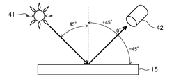
- Explanatory drawing of the reflected light which concerns on calculation of FI value.
- the graph which shows an example of the angle dependence of Y (10 degrees) in the state which does not contain the coloring material of a glittering material content layer.
- Explanatory drawing which shows the measuring method of Y value.
- the graph which shows the preferable range of Y (10 degrees) and the coloring material density
- concentration C in the coefficient k 0.4.
- concentration C in the coefficient k 0.2.
- concentration C in the coefficient k 0.6.
- FIG. The graph which shows the range where FI value becomes 30 or more regarding Y (10 degrees), the coefficient k, and the coloring material density
- FIG. The graph which shows the range where FI value becomes 35 or more regarding Y (10 degrees), the coefficient k, and the coloring material density
- the laminated coating film 12 provided on the surface of the vehicle body (steel plate) 11 of the automobile of this embodiment is formed by laminating a colored underlayer 14, a glittering material-containing layer 15, and a transparent clear layer 16 in this order.
- An electrodeposition coating (undercoat) 13 is formed on the surface of the vehicle body 11 by cationic electrodeposition coating, and the laminated coating 12 is provided on the electrodeposition coating 13.
- the colored underlayer 14 corresponds to an intermediate coating
- the glittering material-containing layer 15 and the transparent clear layer 16 correspond to a top coating.
- a dark pigment 21 is dispersed in the colored base layer 14.
- a dark pigment 23 having the same color as the pigment 21 of the flake-like glittering material 22 and the colored underlayer 14 is dispersed.
- pigments 21 and 23 pigments of various hues such as black pigments such as carbon black, perylene black, and aniline black, or red pigments such as perylene red can be employed.
- Carbon black having a particle size distribution having a peak in a particle size range of 300 nm or more and 500 nm or less is adopted as the pigment 21, and carbon black having a particle size distribution having a peak in a particle size range of 200 nm or less is adopted as the pigment 23. Is particularly preferred.
- the surface smoothness of the colored underlayer 14 is 8 or less as measured by WaveScanWDOI (trade name) manufactured by BYK-Gardner, and the thickness of the glittering material-containing layer 15 is 1.5 ⁇ m or more and 6 ⁇ m. It is as follows.
- the glitter material 22 of the glitter material-containing layer 15 has a thickness of 25 nm or more and 200 nm or less, and is oriented so as to be substantially parallel to the surface of the glitter material-containing layer 15. That is, the orientation angle of the glitter material 22 with respect to the surface of the glitter material containing layer 15 is 3 degrees or less.
- the orientation angle of the glitter material 22 is reduced by utilizing the fact that the coating film is contracted and thinned by evaporation of the solvent by baking. Arrange them to be 3 degrees or less (preferably 2 degrees or less).
- the resin component of the colored base layer 14 for example, a polyester-based resin can be employed, and as the resin component of the glittering material-containing layer 15, for example, an acrylic-based resin can be employed.
- an acrylic-based resin for example, an acrylic-based resin can be employed.
- an acid epoxy curable acrylic resin can be employed.
- the pigment 23 contained in the glittering material-containing layer 15 contributes to increasing the FI value by absorbing the scattered light.
- the FI value increases.
- Dashed arrows indicate that the scattered light is weakened by the pigment 23.
- the scattered light reaching the colored underlayer 14 is absorbed by the colored underlayer 14. That is, irregular reflection is suppressed. As a result, the FI value increases.
- the FI value is 45 from the regular reflection direction to the incident direction side when light is incident on the surface of the laminated coating film 12 at an angle of 45 ° from the normal to the surface.
- the value is obtained by the following equation.
- FIG. 5 shows an example of the angle-dependent characteristics of the Y value calibrated with a standard white plate of the XYZ color system in a state where the coloring material of the glittering material-containing layer is not included.
- FIG. 6 shows a method for measuring the Y value.
- the irradiation angle of the light source 41 to the glittering material-containing layer 15 is 45 °.
- the light receiving angle by the sensor 42 is 0 ° in the regular reflection direction.
- GCMS-4 a three-dimensional variable angle spectrophotometric system manufactured by Murakami Color Research Co., Ltd.
- the Y value of the reflected light measured at a light receiving angle (tilt angle from the regular reflection direction to the light source side) of 10 ° is Y (10 °)
- the Y value of the reflected light measured at a light receiving angle of 20 ° is Y (20 °).
- k is a coefficient, and 0.2 ⁇ k ⁇ 0.6. This will be specifically described below.
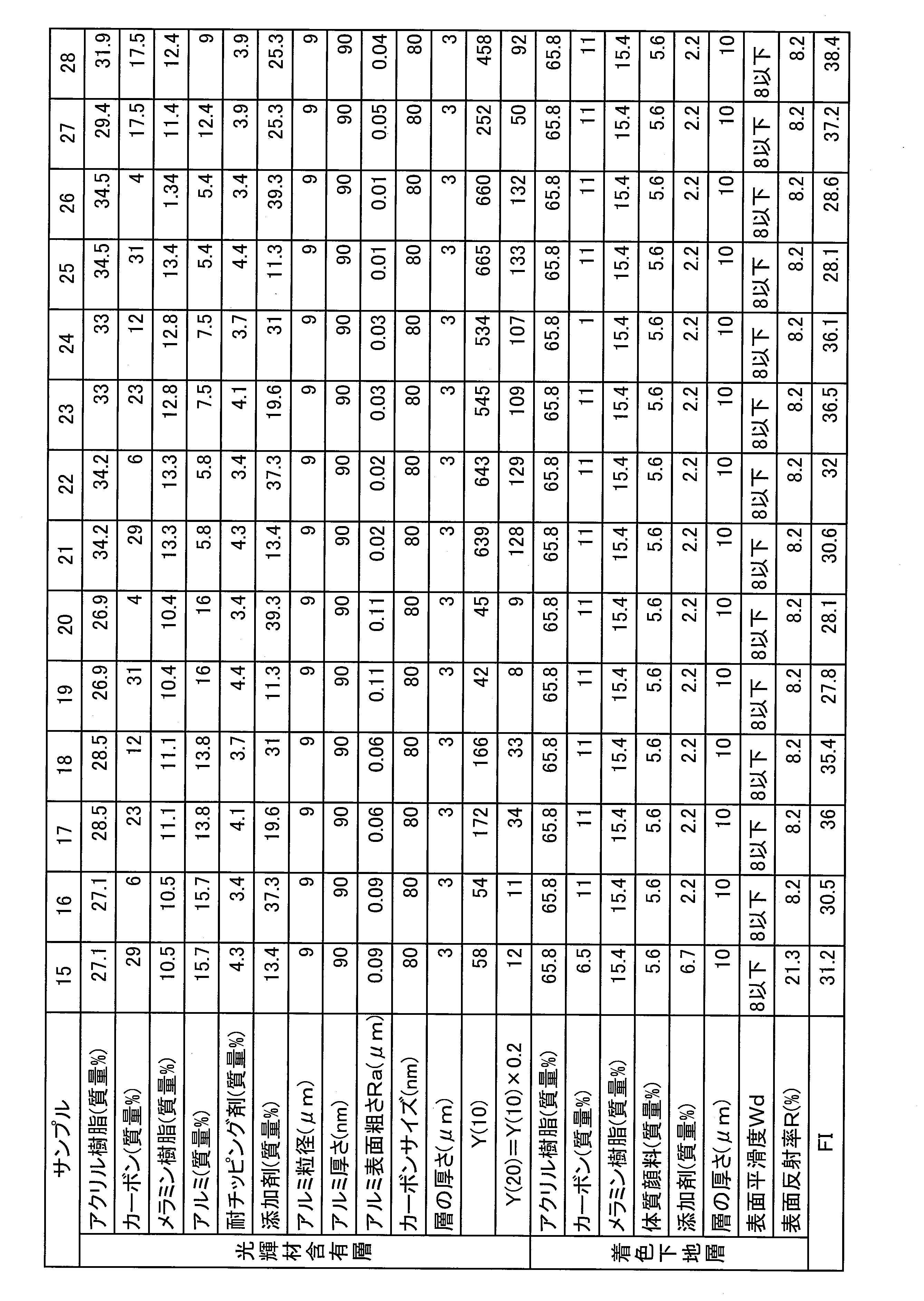
- FI value of each of the laminated coating films (the base is an electrodeposition coating film) provided with the glittering material-containing layer and the colored base layer of Sample 1-42 shown in Table 1-3 was determined.
- Sample 1-42 is an example of a laminated coating film that develops gray.
- the extender pigment for the colored underlayer is barium sulfate.
- the thickness of each colored underlayer is 10 ⁇ m.
- Each paint of the colored underlayer and the glittering material-containing layer was applied on a steel material by wet-on-wet and then baked (heated at 140 ° C. for 20 minutes).
- the FI value is 100 ⁇ Y (10 °) ⁇ 700 and 10 ⁇ C ⁇ 35. 30 or more. Further, when 200 ⁇ Y (10 °) ⁇ 600 and 15 ⁇ C ⁇ 30, the FI value becomes 35 or more.
- the coordinates (x, y, z) given to the vertices a to h of the figure showing the preferred range (the range where FI is 30 or more and the range where FI is 35 or more) are Y (10 °), k
- the coordinates of the three-dimensional orthogonal coordinate space in which the three variables C and C are placed on the x, y, and z coordinate axes are displayed.
- This coordinate is given to the vertices a ′ to h ′ and a ′′ to h ′′ of the figure showing the preferred ranges of FIG. 8 and FIG. 9 (the range where FI is 30 or more and the range where FI is 35 or more).
- the coordinates (x, y, z) are the same.
- the amount of light reaching the colored underlayer increases as the colorant concentration C of the glittering material-containing layer decreases and as Y (10 °) decreases.
- the surface reflectance R of sample 1 is 28.1%
- the surface reflectance R of sample 2 is 13.6%.
- Table 4 shows the FI values of the laminated coating films according to Samples 1 ′ and 2 ′ in which the surface reflectance R is increased by changing the composition of the colored underlayer for Samples 1 and 2.
- Samples 1 ′ and 2 ′ are different from Samples 1 and 2 only in the composition of the colored base layer, and the other coating film configurations are the same as Samples 1 and 2, but the surface reflectance R is increased. In this case, the FI value is less than 30.
- the line Lab in the figure is based on the surface reflectance R and FI value of samples 1, 2, 1 ′, 2 ′, and is a colored underlayer that is expected to have an FI value of 30 or more in the ab line. It is a critical line of surface reflectance R.
- Samples 15, 16, 15 ′, 16 ′ and 29, 30, 29 ′, 30 ′ are plotted in FIG. 10, and based on the surface reflectance R and FI value of these samples, the FI value may be 30 or more.
- Critical lines La′b ′ and La ′′ b ′′ of the expected surface reflectance R were formulated.
- the slopes of the critical lines Lab, La′b ′, and La ′′ b ′′ of the surface reflectance R with respect to the colorant concentration C are 0.6.
- critical lines Lab, La′b ′ and La ′′ b ′′ shown in FIG. 10 correspond to the lines ab, a′b ′ and a ′′ b ′′ in FIGS. 7 to 9, respectively.
- the ab, a′b ′, and a ′′ b ′′ lines are Y (10 °) lines with the largest amount of light reaching the colored base layer.
- Y (10 °) is larger than each line of ab, a′b ′ and a ′′ b ′′, the amount of light reaching decreases, so the upper limit of the surface reflectance R that can obtain an FI value of 30 or more. Becomes higher than each critical line shown in FIG.
- FIG. 11 shows the vertices a to h, a ′ to h ′, and a ′′ to h ′′ of FIGS. 7 to 9 in the two-dimensional orthogonal coordinate system in which two variables of Y (10 °) and coefficient k are set as coordinate axes. Plotting shows the relationship between Y (10 °) and coefficient k. Thus, the preferable range of the coefficient k differs depending on Y (10 °).
- the range where the FI value is 30 or more is shown in FIG.
- the variable can be expressed in the three-dimensional orthogonal coordinate space on the x, y, and z coordinate axes.
- the polyhedral figure shown in FIG. 13 is formed by arranging the vertices a to d, a 'to d', and a "to d" in a three-dimensional orthogonal coordinate space.
- This polyhedron is surrounded by a total of ten planes A to J each including four vertices shown in Table 1.
- the polyhedron shown in FIG. 13 is an octahedron surrounded by a total of eight planes of A plane to H plane. Further, in this octahedron, the C surface and the F surface form a concave ridge angle, and the D surface and the G surface form a convex ridge angle.
- the polyhedron shown in FIG. 13 is surrounded by the planes represented by eight formulas A to H shown in Table 1, and the plane represented by formula C and the plane represented by formula F form a concave ridge angle.
- the surface represented by Formula D and the surface represented by Formula G are octahedrons that form convex ridge angles.
- the range in which the FI value is 35 or more is also represented by the three variables Y (10 °), k, and C as shown in FIG. It can be expressed by the three-dimensional orthogonal coordinate space placed on the x, y, and z coordinate axes. That is, this polyhedron figure is formed by arranging the vertices e to h, e 'to h' and e "to h" in a three-dimensional orthogonal coordinate space, and each of the four vertices shown in Table 2 is formed. A total of 10 planes A ′ to J ′ are included. Table 10 shows the above 10 plane equations.
- the polyhedron shown in FIG. 14 is an octahedron surrounded by a total of eight planes from the A ′ plane to the H ′ plane.
- the C ′ plane and the F ′ plane form a concave ridge angle
- the D ′ plane and the G ′ plane form a convex ridge angle.
- the polyhedron shown in FIG. 14 is surrounded by the planes represented by the eight formulas A ′ to H ′ shown in Table 2, and the plane represented by the formula C ′ and the plane represented by the formula F ′ are It can be said that the concave ridge angle is formed, and the surface represented by the formula D ′ and the surface represented by the formula G ′ are octahedrons forming the convex ridge angle.
- Y (10 °) the coefficient k, and the colorant concentration C satisfy the condition that the coordinates (Y (10 °), k, C) exist within the range defined by the octahedron.
- the FI value is 35 or more.
- Y (10 °) in the state containing the colorant of the glittering material-containing layer is 50.
Abstract
The present invention includes: a colored underlayer (14) that is directly or indirectly formed on the surface of an object (11) to be coated; and a lustrous-material-containing layer (15) that is superposed on the colored underlayer (14), and contains a flaked lustrous material (22) and a colored material (23). With the lustrous-material-containing layer (15) in a state that does not include the colored material, the k value is set in accordance with Y(10°) and the colored material concentration of the lustrous-material-containing layer is set in accordance with the k value, where Y(10°) in the XYZ color system is set to 50-850 inclusive, Y(20°)=k×Y(10°), and 0.2≤k≤0.6. The surface reflectance R(%) of the colored underlayer is set in accordance with Y(10°) and the colored material concentration C of the lustrous-material-containing layer.
Description
本発明は積層塗膜及び塗装物に関する。
The present invention relates to a laminated coating film and a painted product.
一般に自動車の車体や自動車の部品等の基材表面には複数の塗膜が重ねられて基材の保護及び外観の向上が図られている。例えば、特許文献1には、金属板にカチオン電着塗料及び中塗り塗料を塗装してなる被塗物に、濃色顔料(カーボンブラック)を含有する濃色塗料を塗装し、その塗面に鱗片状アルミ顔料を含有するメタリック塗料を塗装し、さらにクリヤ塗料を塗装することが記載されている。濃色塗料の明度をマンセルカラーチャートでN0~5とし、鱗片状アルミ顔料の厚みを0.1~1μm、平均粒径を20μmとすることにより、フリップフロップ性が顕著である積層塗膜を得るというものである。
Generally, a plurality of coating films are stacked on the surface of a base material such as a car body or a car part to protect the base material and improve the appearance. For example, in Patent Document 1, a dark paint containing a dark pigment (carbon black) is applied to an object formed by coating a metal plate with a cationic electrodeposition paint and an intermediate paint, and the coated surface thereof is applied. It is described that a metallic paint containing scaly aluminum pigment is applied, and further a clear paint is applied. By setting the lightness of the dark paint to N0 to 5 on the Munsell color chart, the thickness of the scaly aluminum pigment to 0.1 to 1 μm, and the average particle diameter to 20 μm, a laminated coating film with remarkable flip-flop properties is obtained. That's it.
特許文献2には、平均粒子径D50及び平均厚さが相違する3種類のアルミフレーク顔料A~Cを含有するメタリック塗料組成物について記載されている。アルミフレーク顔料Aは、平均粒子径D50が13~40μm、平均厚さが0.5~2.5μmである。アルミフレーク顔料Bは、平均粒子径D50が13~40μm、平均厚さが0.01~0.5μmである。アルミフレーク顔料Cは、平均粒子径D50が4~13μm、平均厚さが0.01~1.3μmである。アルミフレーク顔料A~Cは、固形分質量比において、A/Bが10/90~90/10とされ、(A+B)/Cが90/10~30/70とされ、樹脂固形分100質量部に対する(A+B+C)量が固形分で5~50質量部とされる。そのような構成にすることにより、輝度感、フリップフロップ性、隠蔽性を改善するというものである。
Patent Document 2 describes a metallic coating composition containing three types of aluminum flake pigments A to C having different average particle diameters D50 and average thicknesses. The aluminum flake pigment A has an average particle diameter D50 of 13 to 40 μm and an average thickness of 0.5 to 2.5 μm. The aluminum flake pigment B has an average particle diameter D50 of 13 to 40 μm and an average thickness of 0.01 to 0.5 μm. The aluminum flake pigment C has an average particle diameter D50 of 4 to 13 μm and an average thickness of 0.01 to 1.3 μm. Aluminum flake pigments A to C have a solid content mass ratio of A / B of 10/90 to 90/10, (A + B) / C of 90/10 to 30/70, and resin solid content of 100 parts by mass. The amount of (A + B + C) is 5 to 50 parts by mass in terms of solid content. By adopting such a configuration, the luminance feeling, flip-flop property, and concealment property are improved.
特許文献3には、樹脂基材にアルミからなる扁平状光輝材を含有する塗料を塗装して光輝性と電磁波透過性を有する光輝性塗膜を得ることが記載されている。その光輝材は、その平面が塗膜表面に沿うように配向され、塗膜表面と直交する直交線の一本と交わる光輝材の数の平均である平均重なり枚数yと、同一の直交線と交わり隣り合う光輝材同士のこの直交線上における距離の平均である平均光輝材間距離xとが所定の関係式を満たすようにされる。
Patent Document 3 describes that a paint containing a flat glitter material made of aluminum is applied to a resin base material to obtain a glitter coating film having glitter and electromagnetic wave transparency. The glitter material is oriented so that its plane is along the surface of the coating film, and the average number of overlapping layers y, which is the average number of glitter materials intersecting with one orthogonal line orthogonal to the coating film surface, and the same orthogonal line The average distance between the bright materials x, which is the average of the distances between the intersecting bright materials on the orthogonal line, satisfies a predetermined relational expression.
車体等にメタリック塗装がされたときに陰影感ないしは金属質感が得られるのは、塗装物を視る角度によって明度が変化するフリップフロップ性(以下、「FF性」という。)による。つまり、明(ハイライト)と暗(シェード)のメリハリが強くなるためである。このFF性は、X-Rite社の指標であるFI(フロップインデックス)値で表すことが多い。しかし、従来、メタリック塗装で実際に得られているFI値は一般には18前後であり、凄みのある高い金属質感を得るに至っていない。
When a metallic paint is applied to the vehicle body, etc., the shading or metal texture is obtained due to the flip-flop property (hereinafter referred to as “FF property”) in which the brightness changes depending on the angle at which the painted object is viewed. That is, the sharpness of light (highlight) and dark (shade) becomes strong. This FF property is often expressed by an FI (flop index) value that is an index of X-Rite. Conventionally, however, the FI value actually obtained by metallic coating is generally around 18, and a tremendous high metal texture has not been obtained.
ここに、光輝材(例えば、アルミフレーク)を光輝材含有層の表面に沿うように配向させると、確かに光輝材による散乱光が少なくなって正反射光が強くなる。その結果、ハイライトでの明度が高くなってシェードでの明度が低くなるから、FI値が高くなる。しかし、光輝材の配向等の制御によって光輝材含有層の正反射が強くなり過ぎると、光を正反射させる一部のみが明るくなる(白っぽく光って見える)。すなわち、入射光の角度に等しい角度から見たときに最も明るく見え、正反射方向の近傍であっても視点の角度がずれるにつれ、明るさが急激に低下する。換言すれば、ハイライト部に広がりがなく、つまり、ある程度の広がりをもって面で輝いている感じが得られず、見映えが悪くなる。
Here, when the glittering material (for example, aluminum flakes) is oriented along the surface of the glittering material-containing layer, the scattered light by the glittering material is certainly reduced and the specular reflection light becomes stronger. As a result, the brightness value at the highlight is increased and the brightness value at the shade is decreased, so that the FI value is increased. However, if the specular reflection of the glittering material-containing layer becomes too strong by controlling the orientation of the glittering material, etc., only a part of the regular reflection of light becomes brighter (looks whitish). That is, it looks brightest when viewed from an angle equal to the angle of the incident light, and the brightness rapidly decreases as the viewpoint angle shifts even in the vicinity of the regular reflection direction. In other words, there is no spread in the highlight portion, that is, a feeling of shining on the surface with a certain extent cannot be obtained, and the appearance is deteriorated.
また、上記FI値は、端的に言えば、シェードでの明度に対する正反射方向近傍の明度の強さを表すから、正反射方向近傍の明度が低いということは、FI値も小さいということである。一方、正反射方向近傍での明度を高めるべく、光輝材による光の散乱を大きくすると、同時にシェードでも明度も高くなり、際だったFF性は得られない。
In short, since the FI value represents the intensity of lightness in the vicinity of the regular reflection direction with respect to the lightness in the shade, a low lightness in the vicinity of the regular reflection direction means that the FI value is also small. . On the other hand, if the scattering of light by the glittering material is increased in order to increase the lightness in the vicinity of the regular reflection direction, the lightness is also increased in the shade at the same time, and an outstanding FF property cannot be obtained.
そこで、本発明は、メタリック塗装において、FF性を改善し、金属質感を高めることを課題とする。
Therefore, an object of the present invention is to improve the FF property and enhance the metal texture in metallic coating.
本発明は、光輝材含有層の光輝材による正反射特性を制御するとともに、光輝材による散乱光を光輝材含有層の着色材及び着色下地層で吸収するようにした。
In the present invention, the regular reflection characteristics of the glittering material-containing layer by the glittering material are controlled, and the scattered light from the glittering material is absorbed by the coloring material and the colored underlayer of the glittering material-containing layer.
ここに開示する積層塗膜は、被塗物の表面に直接又は間接的に形成された着色材を含有する着色下地層と、該着色下地層の上に重ねられた、フレーク状光輝材及び着色材を含有する光輝材含有層とを備え、
上記光輝材含有層の上記着色材を含まない状態でのXYZ表色系の標準白色板で校正したY値に関して、受光角(正反射方向から光源側への傾き角度)10゜で測定した反射光のY値をY(10゜)とし、受光角20゜で測定した反射光のY値をY(20゜)とし、上記光輝材含有層の着色材濃度Cを質量百分率で表すとき、
Y(20゜)=k×Y(10゜)であり(但し、kは係数である。)、
上記Y(10゜)、k及びCは、このY(10゜)、k及びCの3つの変数をx、y及びzの各座標軸におく三次元直交座標空間において、座標(Y(10゜),k,C)が、次の8つの式A~Hで各々表される平面で囲まれ、且つ式Cで表される面と式Fで表される面が凹稜角を形成し、式Dで表される面と式Gで表される面が凸稜角を形成する八面体で区画される範囲内に存するという条件を満足する関係にあり、
式A:3000y-120z+3000=0
式B:3000y-120z=0
式C:5x-3750y-2000=0
式D:5x-3750y+1000=0
式E:15000y-9000=0
式F:5x-1250y-3000=0
式G:5x-1250y=0
式H:15000y-3000=0
上記着色下地層の可視光線の表面反射率R(%)が、上記光輝材含有層のY(10゜)及び着色材濃度Cを用いた次式の条件を満足することを特徴とする。 The laminated coating film disclosed herein includes a colored foundation layer containing a coloring material formed directly or indirectly on the surface of an object to be coated, and a flake-like glittering material and a coloring material superimposed on the colored foundation layer. A glittering material-containing layer containing a material,
Reflection measured at a light receiving angle (tilt angle from the regular reflection direction to the light source side) at 10 ° with respect to the Y value calibrated with the standard white plate of the XYZ color system in the state where the coloring material is not included in the glittering material-containing layer. When the Y value of light is Y (10 °), the Y value of reflected light measured at a light receiving angle of 20 ° is Y (20 °), and the colorant concentration C of the glittering material-containing layer is expressed by mass percentage,
Y (20 °) = k × Y (10 °) (where k is a coefficient),
Y (10 °), k, and C are coordinates (Y (10 °) in a three-dimensional orthogonal coordinate space in which the three variables Y (10 °), k, and C are set on the x, y, and z coordinate axes. ), K, C) are surrounded by the planes represented by the following eight formulas A to H, respectively, and the surface represented by the formula C and the plane represented by the formula F form a concave ridge angle. The surface represented by D and the surface represented by the formula G are in a relationship satisfying the condition that they exist within a range defined by an octahedron that forms a convex ridge angle,
Formula A: 3000y-120z + 3000 = 0
Formula B: 3000y-120z = 0
Formula C: 5x-3750y-2000 = 0
Formula D: 5x-3750y + 1000 = 0
Formula E: 15000y-9000 = 0
Formula F: 5x-1250y-3000 = 0
Formula G: 5x-1250y = 0
Formula H: 15000y-3000 = 0
The visible light surface reflectance R (%) of the colored underlayer satisfies the following condition using Y (10 °) and the colorant concentration C of the glittering material-containing layer.
R≦0.6×C+0.04×Y(10゜)+4
ここに、XYZ表色系のY値は明るさ(視感反射率)を表す刺激値である。上記条件によれば、50≦Y(10゜)≦850、0.2≦k≦0.6となる。これは、端的に言えば、正反射方向近傍の明度を高くしていることを意味する。光輝材の縁で生ずる入射光の乱反射(拡散反射)や光輝材の表面による入射光の散乱により、正反射方向近傍の明度が高くなっているものである。 R ≦ 0.6 × C + 0.04 × Y (10 °) +4
Here, the Y value of the XYZ color system is a stimulus value representing brightness (luminous reflectance). According to the above conditions, 50 ≦ Y (10 °) ≦ 850 and 0.2 ≦ k ≦ 0.6. In short, this means that the brightness in the vicinity of the regular reflection direction is increased. The brightness in the vicinity of the regular reflection direction is high due to irregular reflection (diffuse reflection) of incident light generated at the edge of the bright material and scattering of incident light from the surface of the bright material.
なお、本明細書では、「乱反射(拡散反射)」は、入射光が様々な角度で反射する現象の意味に使用し、「散乱」は入射光がその方向を別の方向に変えられる現象の意味に使用している。
In this specification, “diffuse reflection (diffuse reflection)” is used to mean a phenomenon in which incident light is reflected at various angles, and “scattering” is a phenomenon in which incident light can change its direction to another direction. Used for meaning.
そうして、塗装物がある程度の広がりをもった面で輝くように、且つ際だったFF性を得る上で有利になるように、正反射方向から光源側への傾き角度が大きいシェードに近い側のY値であるY(20゜)を上記Y(10゜)に応じた適宜の低下率(係数k)で低下させている(図11参照)。上記Y(10゜)、k及びCに係る条件によれば、例えば、Y(10゜)=100のとき、kは概略0.2~0.4、従って、Y(20゜)は20~40となる。Y(10゜)=400のとき、kは0.2~0.6、従って、Y(20゜)は80~240となる。Y(10゜)=700のとき、kは約0.4~0.6、従って、Y(20゜)は280~420となる。
Then, it is close to a shade with a large inclination angle from the specular reflection direction to the light source side so that the paint shines on a surface with a certain extent of spread and is advantageous in obtaining outstanding FF properties. Y (20 °), which is the Y value on the side, is reduced at an appropriate reduction rate (coefficient k) corresponding to Y (10 °) (see FIG. 11). According to the above Y (10 °), k and C conditions, for example, when Y (10 °) = 100, k is approximately 0.2 to 0.4, and therefore Y (20 °) is 20 to 40. When Y (10 °) = 400, k is 0.2 to 0.6, and therefore Y (20 °) is 80 to 240. When Y (10 °) = 700, k is about 0.4 to 0.6, and therefore Y (20 °) is 280 to 420.
すなわち、Y(10゜)が相対的に低いケースでは、係数kを小さな値にすることにより、Y(10゜)からY(20゜)への低下余裕幅が小さいなかでも、Y(20゜)をできるだけ大きく低下させて、FF性を高めることができるようにしている。一方、Y(10゜)が相対的に高いケースでは、係数kを小さくするとY値の変化幅が大きくなり過ぎることになる。例えば、Y(10゜)=700において、k=0.2にすると、Y(20゜)=140となり、Y値の変化幅が大きい。その場合、視点の角度のずれに伴って明度が急変する結果となる。そこで、Y(10゜)が相対的に高いケースでは、係数kを大きくしている。
In other words, in the case where Y (10 °) is relatively low, Y (20 °) can be obtained even if the margin of decrease from Y (10 °) to Y (20 °) is small by reducing the coefficient k. ) Is reduced as much as possible to improve the FF property. On the other hand, in the case where Y (10 °) is relatively high, if the coefficient k is decreased, the change range of the Y value becomes too large. For example, if Y (10 °) = 700 and k = 0.2, then Y (20 °) = 140, and the variation range of the Y value is large. In that case, the result is that the brightness changes suddenly as the angle of view changes. Therefore, in the case where Y (10 °) is relatively high, the coefficient k is increased.
また、上記Y(10゜)、k及びCに係る条件によれば、光輝材含有層の着色材濃度C(質量%)は、5質量%以上40質量%以下となる。着色材濃度Cが高くなるほど、光輝材による拡散反射光が着色材によって吸収されるから、FFが良くなる。但し、着色材濃度Cが高くなりすぎると、光輝材による反射光が隠蔽され、所期の発色効果が得られなくなる。また、着色材濃度C(質量%)は、Y(20゜)=k×Y(10゜)の係数kに応じて異なる(図12参照)。例えば、k=0.2であるときは、5≦C≦30となり、k=0.4であるときは、10≦C≦35となり、k=0.6であるときは、15≦C≦40となる。
Further, according to the conditions relating to the above Y (10 °), k, and C, the colorant concentration C (mass%) of the glittering material-containing layer is 5 mass% or more and 40 mass% or less. The higher the colorant concentration C, the better the FF because diffused and reflected light from the glittering material is absorbed by the colorant. However, if the colorant concentration C becomes too high, the reflected light from the glittering material is concealed, and the desired coloring effect cannot be obtained. The colorant concentration C (mass%) varies depending on the coefficient k of Y (20 °) = k × Y (10 °) (see FIG. 12). For example, when k = 0.2, 5 ≦ C ≦ 30, when k = 0.4, 10 ≦ C ≦ 35, and when k = 0.6, 15 ≦ C ≦ 30. 40.
すなわち、係数kの値が小さいときは着色材濃度Cが低く、係数kの値が大きくなるほど、着色材濃度Cが高くなる。先に述べたように、係数kが小さいケースはY(10゜)が相対的に低いケースである。このときは、光輝材による拡散反射が少ない(弱い)から、着色材による拡散反射光の吸収の要求が低い。そのため、着色材濃度Cを低くしている。一方、係数kが大きいケースはY(10゜)が相対的に高いケースである。このときは、光輝材による拡散反射が強いから、着色材によって拡散反射光を吸収すべく、すなわち、FF性を高めるべく、着色材濃度Cを高くしている。
That is, when the value of the coefficient k is small, the colorant concentration C is low, and as the coefficient k is large, the colorant concentration C is high. As described above, the case where the coefficient k is small is a case where Y (10 °) is relatively low. In this case, since the diffuse reflection by the bright material is small (weak), the demand for absorption of the diffuse reflected light by the coloring material is low. Therefore, the colorant concentration C is lowered. On the other hand, a case where the coefficient k is large is a case where Y (10 °) is relatively high. At this time, since the diffuse reflection by the bright material is strong, the colorant concentration C is increased to absorb the diffuse reflection light by the colorant, that is, to improve the FF property.
従って、上記積層塗膜によれば、Y(10゜)を大きくし、Y(10゜)からY(20゜)へのY値の低下を上述の如く設定したことにより、塗装物は広がりのある「面」で輝くようになるとともに、際だったFF性を得る上で有利になる。すなわち、光輝材によって乱反射され、或いは散乱される光、特に2つ以上の光輝材間で多重反射する散乱光は、光輝材含有層の着色材によって吸収され、また、光輝材間の隙間を通って着色下地層に達した光は該着色下地層の着色材によって吸収される。この光輝材含有層の着色材及び着色下地層の吸光効果と、上記Y(10゜)→Y(20゜)の低下度合の設定と相俟って、シェードでの明度を大きく落とすことができる。
Therefore, according to the above-mentioned laminated coating film, the coated material spreads by increasing Y (10 °) and setting the decrease in Y value from Y (10 °) to Y (20 °) as described above. It becomes shining on a certain “surface”, and it is advantageous for obtaining outstanding FF characteristics. That is, light that is diffusely reflected or scattered by the glitter material, particularly scattered light that is multiple-reflected between two or more glitter materials, is absorbed by the coloring material of the glitter material-containing layer and passes through the gaps between the glitter materials. The light reaching the colored underlayer is absorbed by the coloring material of the colored underlayer. Combined with the light absorption effect of the colorant and colored underlayer of the glittering material-containing layer and the setting of the degree of decrease of Y (10 °) → Y (20 °), the brightness in the shade can be greatly reduced. .
換言すれば、上述の如く、Y(10゜)→Y(20゜)の低下度合を設定したことにより、光輝材含有層の着色材及び着色下地層によってシェードの明度を調整することが容易になり、FF性の向上に有利になる。
In other words, as described above, by setting the degree of decrease of Y (10 °) → Y (20 °), it is easy to adjust the brightness of the shade by the coloring material and the colored underlayer of the glittering material-containing layer. It becomes advantageous for improvement of FF property.
ここに、光の吸収層となる着色下地層の表面反射率R(%)は「R≦0.6×C+0.04×Y(10゜)+4」の条件を満足するようにしている。すなわち、光輝材含有層の着色材の量が少なくなるほど、また、光輝材含有層のY(10゜)が小さくなるほど、光輝材含有層を通って着色下地層に到達する光量が多くなる。その場合、シェードでの明度を落とすためには、着色下地層の吸光効果を大きくする必要がある。そこで、表面反射率Rを着色材濃度C及びY(10゜)に比例させ、着色材濃度Cが小さくなるほど、また、Y(10゜)が小さくなるほど、表面反射率Rが小さくなる(光をよく吸収する)ようにしている。
Here, the surface reflectance R (%) of the colored base layer serving as the light absorption layer satisfies the condition of “R ≦ 0.6 × C + 0.04 × Y (10 °) +4”. That is, as the amount of the coloring material in the glittering material-containing layer decreases and as Y (10 °) of the glittering material-containing layer decreases, the amount of light that reaches the colored base layer through the glittering material-containing layer increases. In that case, in order to reduce the lightness in the shade, it is necessary to increase the light absorption effect of the colored underlayer. Therefore, the surface reflectance R is made proportional to the colorant concentrations C and Y (10 °), and the smaller the colorant concentration C is, and the smaller Y (10 °) is, the smaller the surface reflectance R is (the light is reduced). Absorbs well).
また、上記積層塗膜では、上述の如く、着色下地層によって光が吸収されるから、光輝材含有層にはシェードでの明度を落とすための着色材を多量に添加する必要がない。このことは、光輝材の配向性(光輝材を光輝材含有層の表面と平行に配向させること)が良くなること、また、光が光輝材に当たり易くなることを意味し、光輝性の確保、及びハイライトでの明度の増大に有利になる。
Further, in the above-mentioned laminated coating film, as described above, light is absorbed by the colored underlayer, so that it is not necessary to add a large amount of a coloring material for reducing brightness in the shade to the glittering material-containing layer. This means that the orientation of the glittering material (orienting the glittering material in parallel with the surface of the glittering material-containing layer) is improved, and that light easily hits the glittering material. And an increase in brightness at highlights.
上記光輝材としては、アルミ箔を粉砕して得られるアルミフレークを採用すること、さらには、表面の平滑度を高めたアルミフレークを採用することが、輝度を高めて高い金属質感を得る上で好ましい。
In order to increase the brightness and obtain a high metal texture, it is necessary to use aluminum flakes obtained by pulverizing aluminum foil as the glittering material, and further to employ aluminum flakes with improved surface smoothness. preferable.
そのようなアルミフレークの粒径は8μm以上20μm以下であることが好ましい。その粒径が8μm未満になると、配向性が低下する。その粒径が20μmを超えて大きくなると、アルミフレークの一部が光輝材含有層から突出して、耐食性が低下するおそれがある。
The particle size of such aluminum flakes is preferably 8 μm or more and 20 μm or less. When the particle size is less than 8 μm, the orientation deteriorates. When the particle size exceeds 20 μm, a part of the aluminum flakes protrudes from the glittering material-containing layer, and the corrosion resistance may be lowered.
また、アルミフレークの厚さは25nm以上200nm以下であることが好ましい。アルミフレークが過度に薄くなると、該フレークを透過する光の割合が増え、ハイライトでの明度を高くする上で不利になる。また、アルミフレークは、その粒径に対して厚さが薄くなり過ぎると、変形し易くなって配向性に不利になる。その観点から、アルミフレークの厚さはその粒径の0.4%以上であること、例えば30nm以上であることが好ましい。一方、アルミフレークが過度に厚くなると、その配向性が低下し、また、光輝性を確保するために必要な光輝材含有層におけるアルミフレークの体積比が上がり、塗膜物性が低下する。よって、アルミフレークの厚さは200nm以下にすることが好ましい。さらに好ましいのは、アルミフレークの厚さを80nm以上150nm以下にすることである。
The thickness of the aluminum flakes is preferably 25 nm or more and 200 nm or less. If the aluminum flakes become excessively thin, the proportion of light that passes through the flakes increases, which is disadvantageous in increasing the brightness at highlights. In addition, when the aluminum flakes are too thin with respect to the particle diameter, the aluminum flakes are easily deformed, which is disadvantageous for the orientation. From this viewpoint, the thickness of the aluminum flakes is preferably 0.4% or more of the particle size, for example, 30 nm or more. On the other hand, when the aluminum flakes are excessively thick, the orientation thereof is lowered, and the volume ratio of the aluminum flakes in the glittering material-containing layer necessary for securing the glitter is increased, and the physical properties of the coating film are lowered. Therefore, the thickness of the aluminum flakes is preferably 200 nm or less. More preferably, the thickness of the aluminum flake is 80 nm or more and 150 nm or less.
また、アルミフレークは、光の乱反射ないしは散乱を抑えるべく、表面粗さRaが0.1μm以下、さらには0.09μm以下であることが好ましい。また、その表面粗さRaは、アルミフレークによる反射光が過度に強くならないように、0.02μm以上であることが好ましい。
In addition, the aluminum flakes preferably have a surface roughness Ra of 0.1 μm or less, more preferably 0.09 μm or less, in order to suppress irregular reflection or scattering of light. The surface roughness Ra is preferably 0.02 μm or more so that the reflected light from the aluminum flakes does not become excessively strong.
さらに、着色下地層は、その表面平滑度がBYK-Gardner社製WaveScan DOI(商品名)による測定値Wdで8以下であることが好ましい。これにより、光輝材の配向性が良くなり、ハイライトでの明度を高くする上で有利になる。着色下地層の表面平滑度はWdで6以下であることがさらに好ましい。着色下地層の表面粗さRaは光輝材の粒径(8μm以上20μm以下であることが好ましい。)の5%以下であることが好ましい。
Furthermore, the colored underlayer preferably has a surface smoothness of 8 or less as measured by WK-Gardner's WaveScan® DOI (trade name). Thereby, the orientation of the glittering material is improved, which is advantageous in increasing the brightness in highlights. The surface smoothness of the colored underlayer is more preferably 6 or less in terms of Wd. The surface roughness Ra of the colored underlayer is preferably 5% or less of the particle size (preferably 8 μm or more and 20 μm or less) of the glittering material.
光輝材含有層は、その厚さが1.5μm以上6μm以下であることが好ましい。これにより、光輝材の配向性が良くなり、ハイライトでの明度を高くする上で有利になる。光輝材含有層の厚さは、光輝材の粒径の20%以下(1.5μm以上4μm以下)であることがさらに好ましい。光輝材含有層の厚みで光輝材の配向角(光輝材含有層表面と光輝材がなす角度)を規制するためであり、光輝材含有層の厚さが薄くなることによって、光輝材の配向角が小さくなる。好ましいのは、光輝材の配向角が3度以下に、さらには2度以下になるようにすることである。
The glittering material-containing layer preferably has a thickness of 1.5 μm to 6 μm. Thereby, the orientation of the glittering material is improved, which is advantageous in increasing the brightness in highlights. The thickness of the glittering material-containing layer is more preferably 20% or less (1.5 μm or more and 4 μm or less) of the particle diameter of the glittering material. This is to regulate the orientation angle of the glitter material (the angle formed by the glitter material-containing layer surface and the glitter material) by the thickness of the glitter material-containing layer. By reducing the thickness of the glitter material-containing layer, the orientation angle of the glitter material is reduced. Becomes smaller. It is preferable that the orientation angle of the glittering material is 3 degrees or less, and further 2 degrees or less.
好ましい実施形態では、上記着色下地層及び光輝材含有層各々の着色材は、可視光線反射率が低い黒や赤等の濃色系(マンセル明度が5以下)、特に黒色系とされる。上述の如く、本発明は、着色下地層による光の吸収を利用してシェードでの明度を落とすから、着色材として可視光線反射率が低い濃色系着色材を採用するとき、FI値が高くなり、FF性の向上に有利になる。
In a preferred embodiment, the coloring material of each of the colored underlayer and the glittering material-containing layer is a dark color system such as black or red having a low visible light reflectance (Munsell brightness is 5 or less), particularly a black color system. As described above, the present invention uses light absorption by the colored underlayer to reduce the lightness in the shade. Therefore, when a dark colorant having a low visible light reflectance is used as the colorant, the FI value is high. It becomes advantageous for improvement of FF property.
着色材としては、顔料及び染料のいずれをも採用することができ、また、二種以上の着色材を混合して用いることもできる(混色)。
As the colorant, either a pigment or a dye can be used, and two or more kinds of colorants can be mixed and used (mixed color).
好ましい実施形態では、上記着色下地層の着色材と上記光輝材含有層の着色材が同色系とされる。これにより、塗色の濁りが抑えられ、緻密感、深み感、金属質感が高くなる。
In a preferred embodiment, the coloring material of the colored base layer and the coloring material of the glittering material-containing layer are of the same color system. As a result, the turbidity of the coating color is suppressed, and the denseness, depth, and metal texture are enhanced.
ここに、無彩色において同系色というためには、比較対象色のマンセル値での明度差が5.0以下であることが望まれる。有彩色において同系色というためには、マンセル色相環を100分割して比較対象色の一方の色相を基準(0位置)とし、左廻り+50、右廻り-50で表示したとき、比較対象色の他方の色相が±10の色相範囲にあることが望まれる。
Here, in order to be a similar color in an achromatic color, it is desirable that the brightness difference in the Munsell value of the comparison target color is 5.0 or less. In order to make similar colors in chromatic colors, when the Munsell hue circle is divided into 100 and one hue of the comparison target color is set as a reference (0 position), and the counterclockwise rotation is displayed at +50 and clockwise rotation at -50, It is desired that the other hue is within a hue range of ± 10.
好ましい実施形態では、上記着色下地層及び光輝材含有層各々の着色材が黒色系とされる。これにより、FI値が高く、金属質感の高いグレー色を得ることができる。
In a preferred embodiment, the coloring material of each of the colored underlayer and the glittering material-containing layer is black. Thereby, it is possible to obtain a gray color having a high FI value and a high metal texture.
好ましい実施態様では、上記光輝材含有層の上に透明クリヤ層が直接積層される。従って、透明クリヤ層によって耐酸性や耐擦り傷性を得ることができる。
In a preferred embodiment, a transparent clear layer is directly laminated on the glittering material-containing layer. Therefore, acid resistance and scratch resistance can be obtained by the transparent clear layer.
被塗物に上記積層塗膜を備えた塗装物としては、例えば、自動車のボディがあり、また、自動二輪車、その他の乗物のボディであってもよく、或いはその他の金属製品や樹脂製品であってもよい。
Examples of the coated object having the above-mentioned laminated coating film on the object to be coated include an automobile body, a motorcycle, other vehicle bodies, and other metal products and resin products. May be.
本発明によれば、着色材を含有する着色下地層に、フレーク状光輝材及び着色材を含有する光輝材含有層を重ね、光輝材含有層は、着色材を含まない状態において、XYZ表色系のY(10゜)を50以上850以下とし、Y(20゜)=k×Y(10゜)として0.2≦k≦0.6とし、Y(10゜)に応じてk値を設定し、k値に応じて光輝材含有層の着色材濃度Cを設定するとともに、光輝材含有層の着色材濃度C及びY(10゜)に応じて着色下地層の表面反射率R(%)を設定したから、塗装物がある程度の広がりのある「面」で輝くようになるとともに、際だったFF性を得ることができる。
According to the present invention, a luminescent material-containing layer containing a flake-like glitter material and a colorant is overlaid on a colored underlayer containing a colorant, and the glitter material-containing layer contains an XYZ color in a state not containing the colorant. Y (10 °) of the system is set to 50 to 850, Y (20 °) = k × Y (10 °), 0.2 ≦ k ≦ 0.6, and k value is set according to Y (10 °). The colorant concentration C of the glittering material-containing layer is set according to the k value, and the surface reflectance R (%) of the colored base layer is determined according to the coloring material concentration C and Y (10 °) of the glittering material-containing layer. ) Is set, the painted object shines with a "surface" that has a certain extent of spread, and an outstanding FF property can be obtained.
以下、本発明を実施するための形態を図面に基づいて説明する。以下の好ましい実施形態の説明は、本質的に例示に過ぎず、本発明、その適用物或いはその用途を制限することを意図するものではない。
Hereinafter, embodiments for carrying out the present invention will be described with reference to the drawings. The following description of the preferred embodiments is merely exemplary in nature and is not intended to limit the invention, its application, or its use.
<積層塗膜の構成例>
図1に示すように本実施形態の自動車の車体(鋼板)11の表面に設けられた積層塗膜12は、着色下地層14、光輝材含有層15及び透明クリヤ層16を順に積層してなる。車体11の表面にはカチオン電着塗装によって電着塗膜(下塗り)13が形成され、電着塗膜13の上に上記積層塗膜12が設けられている。この積層塗膜12において、着色下地層14は中塗りに相当し、光輝材含有層15及び透明クリヤ層16は上塗りに相当する。 <Configuration example of laminated coating film>
As shown in FIG. 1, thelaminated coating film 12 provided on the surface of the vehicle body (steel plate) 11 of the automobile of this embodiment is formed by laminating a colored underlayer 14, a glittering material-containing layer 15, and a transparent clear layer 16 in this order. . An electrodeposition coating (undercoat) 13 is formed on the surface of the vehicle body 11 by cationic electrodeposition coating, and the laminated coating 12 is provided on the electrodeposition coating 13. In this laminated coating film 12, the colored underlayer 14 corresponds to an intermediate coating, and the glittering material-containing layer 15 and the transparent clear layer 16 correspond to a top coating.
図1に示すように本実施形態の自動車の車体(鋼板)11の表面に設けられた積層塗膜12は、着色下地層14、光輝材含有層15及び透明クリヤ層16を順に積層してなる。車体11の表面にはカチオン電着塗装によって電着塗膜(下塗り)13が形成され、電着塗膜13の上に上記積層塗膜12が設けられている。この積層塗膜12において、着色下地層14は中塗りに相当し、光輝材含有層15及び透明クリヤ層16は上塗りに相当する。 <Configuration example of laminated coating film>
As shown in FIG. 1, the
着色下地層14には、濃色系顔料21が分散している。光輝材含有層15には、フレーク状光輝材22及び着色下地層14の顔料21と同系色の濃色系顔料23が分散している。顔料21,23としては、例えば、カーボンブラック、ペリレンブラック、アニリンブラック等の黒顔料、或いはペリレンレッド等の赤顔料など種々の色相の顔料を採用することができる。顔料21として、300nm以上500nm以下の粒径範囲にピークを有する粒度分布をもつカーボンブラックを採用し、顔料23として、200nm以下の粒径範囲にピークを有する粒度分布をもつカーボンブラックを採用することが特に好ましい。
In the colored base layer 14, a dark pigment 21 is dispersed. In the glittering material-containing layer 15, a dark pigment 23 having the same color as the pigment 21 of the flake-like glittering material 22 and the colored underlayer 14 is dispersed. As the pigments 21 and 23, pigments of various hues such as black pigments such as carbon black, perylene black, and aniline black, or red pigments such as perylene red can be employed. Carbon black having a particle size distribution having a peak in a particle size range of 300 nm or more and 500 nm or less is adopted as the pigment 21, and carbon black having a particle size distribution having a peak in a particle size range of 200 nm or less is adopted as the pigment 23. Is particularly preferred.
着色下地層14の表面平滑度はBYK-Gardner社製WaveScan DOI(商品名)による測定値Wd(波長3~10mm)で8以下であり、光輝材含有層15の厚さは1.5μm以上6μm以下である。
The surface smoothness of the colored underlayer 14 is 8 or less as measured by WaveScanWDOI (trade name) manufactured by BYK-Gardner, and the thickness of the glittering material-containing layer 15 is 1.5 μm or more and 6 μm. It is as follows.
光輝材含有層15の光輝材22は、厚さが25nm以上200nm以下であり、当該光輝材含有層15の表面と略平行になるように配向されている。すなわち、光輝材含有層15の表面に対する光輝材22の配向角は3度以下である。光輝材22及び顔料23を含有する塗料を着色下地層14の上に塗布した後、焼付けによる溶剤の蒸発によって塗膜が体積収縮して薄くなることを利用して、光輝材22を配向角が3度以下(好ましくは2度以下)になるように並べる。
The glitter material 22 of the glitter material-containing layer 15 has a thickness of 25 nm or more and 200 nm or less, and is oriented so as to be substantially parallel to the surface of the glitter material-containing layer 15. That is, the orientation angle of the glitter material 22 with respect to the surface of the glitter material containing layer 15 is 3 degrees or less. After applying the paint containing the glitter material 22 and the pigment 23 on the colored base layer 14, the orientation angle of the glitter material 22 is reduced by utilizing the fact that the coating film is contracted and thinned by evaporation of the solvent by baking. Arrange them to be 3 degrees or less (preferably 2 degrees or less).
着色下地層14の樹脂成分としては、例えば、ポリエステル系樹脂を採用することができ、光輝材含有層15の樹脂成分としては、例えば、アクリル系樹脂を採用することができ、透明クリヤ層16の樹脂成分としては、例えば酸エポキシ硬化型アクリル樹脂を採用することができる。
As the resin component of the colored base layer 14, for example, a polyester-based resin can be employed, and as the resin component of the glittering material-containing layer 15, for example, an acrylic-based resin can be employed. As the resin component, for example, an acid epoxy curable acrylic resin can be employed.
<散乱光等の制御>
図2に示すように、光輝材含有層30に多数の光輝材22が分散している場合、光は複数の光輝材22によって繰り返し反射される。このような多重反射を経て正反射方向から外れて光輝材含有層30から出て行く散乱光が多くなると、FI値は低くなる。すなわち、FI値を高くするには、上記散乱光を減らすことが重要になる。また、多重反射を経て下地層31に達する光は、この下地層31で乱反射(拡散反射)される。この乱反射が強くなると、FI値が低くなる。従って、FI値を高くするには、下地層31による乱反射を抑えることが重要になる。 <Control of scattered light, etc.>
As shown in FIG. 2, when a large number ofglitter materials 22 are dispersed in the glitter material-containing layer 30, the light is repeatedly reflected by the plurality of glitter materials 22. When the scattered light that goes out of the specular reflection direction and goes out of the bright material-containing layer 30 through such multiple reflections increases, the FI value decreases. That is, to increase the FI value, it is important to reduce the scattered light. In addition, light reaching the base layer 31 through multiple reflections is irregularly reflected (diffuse reflected) by the base layer 31. When this irregular reflection becomes stronger, the FI value becomes lower. Therefore, in order to increase the FI value, it is important to suppress irregular reflection by the base layer 31.
図2に示すように、光輝材含有層30に多数の光輝材22が分散している場合、光は複数の光輝材22によって繰り返し反射される。このような多重反射を経て正反射方向から外れて光輝材含有層30から出て行く散乱光が多くなると、FI値は低くなる。すなわち、FI値を高くするには、上記散乱光を減らすことが重要になる。また、多重反射を経て下地層31に達する光は、この下地層31で乱反射(拡散反射)される。この乱反射が強くなると、FI値が低くなる。従って、FI値を高くするには、下地層31による乱反射を抑えることが重要になる。 <Control of scattered light, etc.>
As shown in FIG. 2, when a large number of
図3に示すように、光輝材含有層15に含まれる顔料23は、上記散乱光を吸収することでFI値を高めることに寄与する。多重反射によって光路長が長くなることにより、光が顔料23によって吸収されやすくなり、その結果、FI値が高くなる。破線の矢符は顔料23によって散乱光が弱くなっていることを示している。また、着色下地層14に達した散乱光はこの着色下地層14で吸収される。つまり、乱反射が抑えられる。その結果、FI値が高くなる。
As shown in FIG. 3, the pigment 23 contained in the glittering material-containing layer 15 contributes to increasing the FI value by absorbing the scattered light. By increasing the optical path length due to multiple reflection, light is easily absorbed by the pigment 23, and as a result, the FI value increases. Dashed arrows indicate that the scattered light is weakened by the pigment 23. Further, the scattered light reaching the colored underlayer 14 is absorbed by the colored underlayer 14. That is, irregular reflection is suppressed. As a result, the FI value increases.
また、光輝材22の面積占有率が低くなると、光輝材22によって正反射される光量が少なくなり、FI値を高めることに不利になる。一方、光輝材22の面積占有率が高くなると、光輝材22による光の多重反射回数が多くなり、その結果、散乱光が増えるため、FI値を高くすることに不利になる。
In addition, when the area occupancy of the glitter material 22 is reduced, the amount of light regularly reflected by the glitter material 22 is reduced, which is disadvantageous for increasing the FI value. On the other hand, when the area occupancy ratio of the glitter material 22 increases, the number of times of multiple reflection of light by the glitter material 22 increases, and as a result, scattered light increases, which is disadvantageous for increasing the FI value.
ここに、FI値は、図4に示すように、積層塗膜12の表面に対して該表面の垂線から45゜傾けた角度で光を入射したときの、正反射方向から入射方向側に45°傾けた反射光(45゜反射光)の明度指数L*45°と、正反射方向から入射方向側に15°傾けた反射光(15゜反射光)の明度指数L*15°と、正反射方向から入射方向側に110°傾けた反射光(110゜反射光)の明度指数L*110°とに基いて、次式により求められる値である。
Here, as shown in FIG. 4, the FI value is 45 from the regular reflection direction to the incident direction side when light is incident on the surface of the laminated coating film 12 at an angle of 45 ° from the normal to the surface. The lightness index L * 45 ° of the reflected light (45 ° reflected light) tilted, and the lightness index L * 15 ° of the reflected light (15 ° reflected light) tilted 15 ° from the regular reflection direction to the incident direction side. Based on the lightness index L * 110 ° of the reflected light (110 ° reflected light) tilted by 110 ° from the reflection direction to the incident direction side, the value is obtained by the following equation.
FI=2.69×(L*15°-L*110°)1.11/L*45°0.86
<光輝材含有層について>
図5は光輝材含有層の着色材を含まない状態でのXYZ表色系の標準白色板で校正したY値の角度依存特性の一例を示す。図6にY値の測定方法を示す。光源41の光輝材含有層15に対する照射角は45゜である。センサ42による受光角は正反射方向を0゜としている。測定には株式会社村上色彩研究所製三次元変角分光測色システムGCMS-4を用いた。受光角(正反射方向から光源側への傾き角度)10゜で測定した反射光のY値をY(10゜)、受光角20゜で測定した反射光のY値をY(20゜)とすると、図5の例では、Y(10゜)=510、Y(20゜)=200である。 FI = 2.69 × (L * 15 ° −L * 110 °) 1.11 / L * 45 ° 0.86
<About glittering material-containing layer>
FIG. 5 shows an example of the angle-dependent characteristics of the Y value calibrated with a standard white plate of the XYZ color system in a state where the coloring material of the glittering material-containing layer is not included. FIG. 6 shows a method for measuring the Y value. The irradiation angle of thelight source 41 to the glittering material-containing layer 15 is 45 °. The light receiving angle by the sensor 42 is 0 ° in the regular reflection direction. For the measurement, GCMS-4, a three-dimensional variable angle spectrophotometric system manufactured by Murakami Color Research Co., Ltd., was used. The Y value of the reflected light measured at a light receiving angle (tilt angle from the regular reflection direction to the light source side) of 10 ° is Y (10 °), and the Y value of the reflected light measured at a light receiving angle of 20 ° is Y (20 °). Then, in the example of FIG. 5, Y (10 °) = 510 and Y (20 °) = 200.
<光輝材含有層について>
図5は光輝材含有層の着色材を含まない状態でのXYZ表色系の標準白色板で校正したY値の角度依存特性の一例を示す。図6にY値の測定方法を示す。光源41の光輝材含有層15に対する照射角は45゜である。センサ42による受光角は正反射方向を0゜としている。測定には株式会社村上色彩研究所製三次元変角分光測色システムGCMS-4を用いた。受光角(正反射方向から光源側への傾き角度)10゜で測定した反射光のY値をY(10゜)、受光角20゜で測定した反射光のY値をY(20゜)とすると、図5の例では、Y(10゜)=510、Y(20゜)=200である。 FI = 2.69 × (L * 15 ° −L * 110 °) 1.11 / L * 45 ° 0.86
<About glittering material-containing layer>
FIG. 5 shows an example of the angle-dependent characteristics of the Y value calibrated with a standard white plate of the XYZ color system in a state where the coloring material of the glittering material-containing layer is not included. FIG. 6 shows a method for measuring the Y value. The irradiation angle of the
本発明は、塗装物がある程度の広がりのある「面」で輝くようにするとともに、際だったFF性を得るために、50≦Y(10゜)≦850、Y(20゜)=k×Y(10゜)とし、Y(10゜)、k及び光輝材含有層の着色材濃度C(質量%)が、所定の条件を満足する関係になるようにしている。ここに、kは係数であり、0.2≦k≦0.6である。以下、具体的に説明する。
According to the present invention, in order to make the coated object shine on a “surface” having a certain extent of spread, and to obtain outstanding FF properties, 50 ≦ Y (10 °) ≦ 850, Y (20 °) = k × Y (10 °) is set such that Y (10 °), k and the colorant concentration C (% by mass) of the glittering material-containing layer satisfy a predetermined condition. Here, k is a coefficient, and 0.2 ≦ k ≦ 0.6. This will be specifically described below.
<好ましいY(10゜)、係数k、着色材濃度C及び表面反射率Rの策定>
表1-3に示すサンプル1-42の光輝材含有層及び着色下地層を備えた積層塗膜(下地は電着塗膜)各々のFI値を求めた。サンプル1-42は、グレーを発色させる積層塗膜の例である。着色下地層の体質顔料は硫酸バリウムである。着色下地層の厚さはいずれも10μmである。着色下地層及び光輝材含有層の各塗料を鋼材にウェットオンウェットで塗装した後に、焼付け(140℃で20分間加熱)を行なった。 <Preferable Y (10 °), coefficient k, colorant concentration C and surface reflectance R>
The FI value of each of the laminated coating films (the base is an electrodeposition coating film) provided with the glittering material-containing layer and the colored base layer of Sample 1-42 shown in Table 1-3 was determined. Sample 1-42 is an example of a laminated coating film that develops gray. The extender pigment for the colored underlayer is barium sulfate. The thickness of each colored underlayer is 10 μm. Each paint of the colored underlayer and the glittering material-containing layer was applied on a steel material by wet-on-wet and then baked (heated at 140 ° C. for 20 minutes).


結果を図7-9に示す。同図では、表1-3のサンプル番号に係るプロットを丸数字で示している。
The results are shown in Figure 7-9. In the figure, the plots relating to the sample numbers in Table 1-3 are indicated by circled numbers.
図7に示すように、光輝材含有層に関しては、k=0.4であるときは、100≦Y(10゜)≦700であり、且つ10≦C≦35であるときに、FI値が30以上となる。また、200≦Y(10゜)≦600であり、且つ15≦C≦30であるときに、FI値が35以上となる。同図の好ましい範囲(FIが30以上になる範囲及びFIが35以上になる範囲)を示す図形の頂点a~hに与えた座標(x,y,z)は、Y(10゜)、k及びCの3つの変数をx、y及びzの各座標軸におく三次元直交座標空間の座標を表示したものである。この座標に関しては、図8及び図9の好ましい範囲(FIが30以上になる範囲及びFIが35以上になる範囲)を示す図形の頂点a'~h',a''~h''に与えた座標(x,y,z)も同じである。
As shown in FIG. 7, regarding the glittering material-containing layer, when k = 0.4, the FI value is 100 ≦ Y (10 °) ≦ 700 and 10 ≦ C ≦ 35. 30 or more. Further, when 200 ≦ Y (10 °) ≦ 600 and 15 ≦ C ≦ 30, the FI value becomes 35 or more. The coordinates (x, y, z) given to the vertices a to h of the figure showing the preferred range (the range where FI is 30 or more and the range where FI is 35 or more) are Y (10 °), k The coordinates of the three-dimensional orthogonal coordinate space in which the three variables C and C are placed on the x, y, and z coordinate axes are displayed. This coordinate is given to the vertices a ′ to h ′ and a ″ to h ″ of the figure showing the preferred ranges of FIG. 8 and FIG. 9 (the range where FI is 30 or more and the range where FI is 35 or more). The coordinates (x, y, z) are the same.
同じく、k=0.2であるときは、図8に示すように、50≦Y(10゜)≦650であり、且つ5≦C≦30であるときに、FI値が30以上となる。そして、150≦Y(10゜)≦550であり、且つ10≦C≦25であるときに、FI値が35以上となる。
Similarly, when k = 0.2, as shown in FIG. 8, when 50 ≦ Y (10 °) ≦ 650 and 5 ≦ C ≦ 30, the FI value is 30 or more. When 150 ≦ Y (10 °) ≦ 550 and 10 ≦ C ≦ 25, the FI value is 35 or more.
同じく、k=0.6であるときは、図9に示すように、250≦Y(10゜)≦850であり、且つ15≦C≦40であるときに、FI値が30以上となる。そして、350≦Y(10゜)≦750であり、且つ20≦C≦35であるときに、FI値が35以上となる。
Similarly, when k = 0.6, as shown in FIG. 9, when FI ≦ 250 (Y (10 °) ≦ 850) and 15 ≦ C ≦ 40, the FI value is 30 or more. When 350 ≦ Y (10 °) ≦ 750 and 20 ≦ C ≦ 35, the FI value is 35 or more.
次に、着色下地層の表面反射率Rについてみると、光輝材含有層の着色材濃度Cが低くなるほど、また、Y(10゜)が小さくなるほど、着色下地層に到達する光量が多くなる。図7(k=0.4)においては、光輝材含有層が頂点bに係る構成であるときに、着色下地層に到達する光量が最も多くなる。そこで、図7の頂点と頂点bを結ぶabラインに沿って並ぶサンプル1,2に基づいて、FI=30を得るために必要な着色下地層の表面反射率Rについて検討する。
Next, regarding the surface reflectance R of the colored underlayer, the amount of light reaching the colored underlayer increases as the colorant concentration C of the glittering material-containing layer decreases and as Y (10 °) decreases. In FIG. 7 (k = 0.4), when the glittering material-containing layer has a configuration related to the apex b, the amount of light reaching the colored base layer is the largest. Therefore, based on samples 1 and 2 arranged along the ab line connecting the apex and the apex b in FIG. 7, the surface reflectance R of the colored underlayer necessary for obtaining FI = 30 will be examined.
表1に示すように、サンプル1の表面反射率Rは28.1%、サンプル2の表面反射率Rは13.6%である。このサンプル1,2に対して、着色下地層の配合を変えて表面反射率Rを大きくしたサンプル1',2'に係る積層塗膜のFI値を表4に示す。サンプル1',2'各々は、着色下地層の配合がサンプル1,2と異なるだけで、他の塗膜構成はサンプル1,2と同じであるが、表面反射率Rが大きくなったことによって、FI値が30未満になったケースである。
As shown in Table 1, the surface reflectance R of sample 1 is 28.1%, and the surface reflectance R of sample 2 is 13.6%. Table 4 shows the FI values of the laminated coating films according to Samples 1 ′ and 2 ′ in which the surface reflectance R is increased by changing the composition of the colored underlayer for Samples 1 and 2. Samples 1 ′ and 2 ′ are different from Samples 1 and 2 only in the composition of the colored base layer, and the other coating film configurations are the same as Samples 1 and 2, but the surface reflectance R is increased. In this case, the FI value is less than 30.

表4によれば、着色下地層の表面反射率Rが積層塗膜のFI値に影響を及ぼすことがわかる。
According to Table 4, it can be seen that the surface reflectance R of the colored underlayer affects the FI value of the laminated coating film.
着色材濃度C及び表面反射率Rの2つの変数を座標軸におく二次元直交座標系に、サンプル1,2,1',2'をプロットすると、図10のようになる。同図のラインLabは、サンプル1,2,1',2'の表面反射率RとFI値に基づいて策定した、上記abラインにおいてFI値が30以上になることが見込まれる着色下地層の表面反射率Rの臨界ラインである。
When the samples 1, 2, 1 ′, and 2 ′ are plotted in a two-dimensional orthogonal coordinate system in which two variables of the colorant concentration C and the surface reflectance R are set as coordinate axes, the result is as shown in FIG. The line Lab in the figure is based on the surface reflectance R and FI value of samples 1, 2, 1 ′, 2 ′, and is a colored underlayer that is expected to have an FI value of 30 or more in the ab line. It is a critical line of surface reflectance R.
同様に、図8(k=0.2)のa'b'ライン、並びに図9(k=0.6)のa''b''ラインについても、当該ラインに沿って並ぶ表4に示すサンプル15,16,15',16'及び29,30,29',30'を図10にプロットし、それらサンプルの表面反射率RとFI値に基づいて、FI値が30以上になることが見込まれる表面反射率Rの臨界ラインLa'b'及びLa''b''を策定した。
Similarly, the a′b ′ line in FIG. 8 (k = 0.2) and the a ″ b ″ line in FIG. 9 (k = 0.6) are also shown in Table 4 arranged along the lines. Samples 15, 16, 15 ′, 16 ′ and 29, 30, 29 ′, 30 ′ are plotted in FIG. 10, and based on the surface reflectance R and FI value of these samples, the FI value may be 30 or more. Critical lines La′b ′ and La ″ b ″ of the expected surface reflectance R were formulated.
図10によれば、表面反射率Rの臨界ラインLab,La'b'及びLa''b''の、着色材濃度Cに対する傾きは0.6である。一方、各ラインの切片が相違するのは、各々のY(10゜)が異なることに基づく。そこで、R=0.6×C+α×Y(10゜)+βとおき、C=0のときのR値及びY(10゜)を代入してα及びβを求めると、α=0.04、β=2となる。
According to FIG. 10, the slopes of the critical lines Lab, La′b ′, and La ″ b ″ of the surface reflectance R with respect to the colorant concentration C are 0.6. On the other hand, the difference in the intercept of each line is based on the fact that each Y (10 °) is different. Therefore, when R = 0.6 × C + α × Y (10 °) + β and R and Y (10 °) when C = 0 are substituted to obtain α and β, α = 0.04, β = 2.
従って、結局のところ、表面反射率Rが次式で表される条件を満足するとき、FI値≧30を確保できることになる。
Therefore, after all, when the surface reflectance R satisfies the condition expressed by the following formula, FI value ≧ 30 can be secured.
R≦0.6×C+0.04×Y(10゜)+4
ここに、図10に示す臨界ラインLab,La'b'及びLa''b''は、図7~図9のab、a'b'及びa''b''の各ラインに対応し、このab、a'b'及びa''b''の各ラインは着色下地層に到達する光量が最も多いY(10゜)ラインである。ab、a'b'及びa''b''の各ラインよりもY(10゜)が大きくなると、到達光量が少なくなるから、FI値30以上を得ることができる表面反射率Rの上限値は図10に示す各臨界ラインを超えて高くなる。 R ≦ 0.6 × C + 0.04 × Y (10 °) +4
Here, critical lines Lab, La′b ′ and La ″ b ″ shown in FIG. 10 correspond to the lines ab, a′b ′ and a ″ b ″ in FIGS. 7 to 9, respectively. The ab, a′b ′, and a ″ b ″ lines are Y (10 °) lines with the largest amount of light reaching the colored base layer. When Y (10 °) is larger than each line of ab, a′b ′ and a ″ b ″, the amount of light reaching decreases, so the upper limit of the surface reflectance R that can obtain an FI value of 30 or more. Becomes higher than each critical line shown in FIG.
例えば、Y(10゜)が500であるときの、当該表面反射率Rの臨界ラインR500は、R500=0.6×C+0.04×500+4=0.6×C+24となる。Y(10゜)が500であるときは、この臨界ラインR500を超えない表面反射率にすれば、FI値30以上が得られることになる。
For example, when Y (10 °) is 500, the critical line R 500 of the surface reflectance R is R 500 = 0.6 × C + 0.04 × 500 + 4 = 0.6 × C + 24. When Y (10 °) is 500, if the surface reflectance does not exceed the critical line R 500 , an FI value of 30 or more can be obtained.
図11は、Y(10゜)及び係数kの2つの変数を座標軸におく二次元直交座標系に上記図7~図9の頂点a~h,a’~h’,a”~h”をプロットして、Y(10゜)と係数kの関係をみたものである。このように、係数kの好ましい範囲はY(10゜)に応じて異なる。
FIG. 11 shows the vertices a to h, a ′ to h ′, and a ″ to h ″ of FIGS. 7 to 9 in the two-dimensional orthogonal coordinate system in which two variables of Y (10 °) and coefficient k are set as coordinate axes. Plotting shows the relationship between Y (10 °) and coefficient k. Thus, the preferable range of the coefficient k differs depending on Y (10 °).
図12は、係数k及び着色材濃度Cの2つの変数を座標軸におく二次元直交座標系に上記頂点a~h,a’~h’,a”~h”をプロットして、係数kと着色材濃度Cの関係をみたものである。このように、着色材濃度Cの好ましい範囲は係数kに応じて異なる。
12 plots the vertices a to h, a ′ to h ′, and a ″ to h ″ in a two-dimensional orthogonal coordinate system in which two variables of the coefficient k and the colorant concentration C are set as coordinate axes. This shows the relationship of the colorant concentration C. Thus, the preferable range of the colorant concentration C differs depending on the coefficient k.
以上を踏まえると、Y(10゜)、係数k及び着色材濃度Cに関し、FI値が30以上となる範囲は、図13に示すように、当該Y(10゜)、k及びCの3つの変数をx、y及びzの各座標軸におく上記三次元直交座標空間で表すことができる。
Based on the above, regarding the Y (10 °), the coefficient k, and the colorant concentration C, the range where the FI value is 30 or more is shown in FIG. The variable can be expressed in the three-dimensional orthogonal coordinate space on the x, y, and z coordinate axes.
すなわち、図13に示す多面体の図形は、上記頂点a~d、a’~d’及びa”~d”を三次元直交座標空間に配置して形成したものである。この多面体は、表1に示す各々4つの頂点を含む合計10個の平面A~Jで囲まれている。
That is, the polyhedral figure shown in FIG. 13 is formed by arranging the vertices a to d, a 'to d', and a "to d" in a three-dimensional orthogonal coordinate space. This polyhedron is surrounded by a total of ten planes A to J each including four vertices shown in Table 1.
三次元直交座標空間(x,y,z)上の平面の式は「αx+βy+γz+δ=0」で表すことができ、上記10個の平面の式は表5のようになる。
The formula of the plane on the three-dimensional orthogonal coordinate space (x, y, z) can be expressed by “αx + βy + γz + δ = 0”, and the formula of the ten planes is as shown in Table 5.
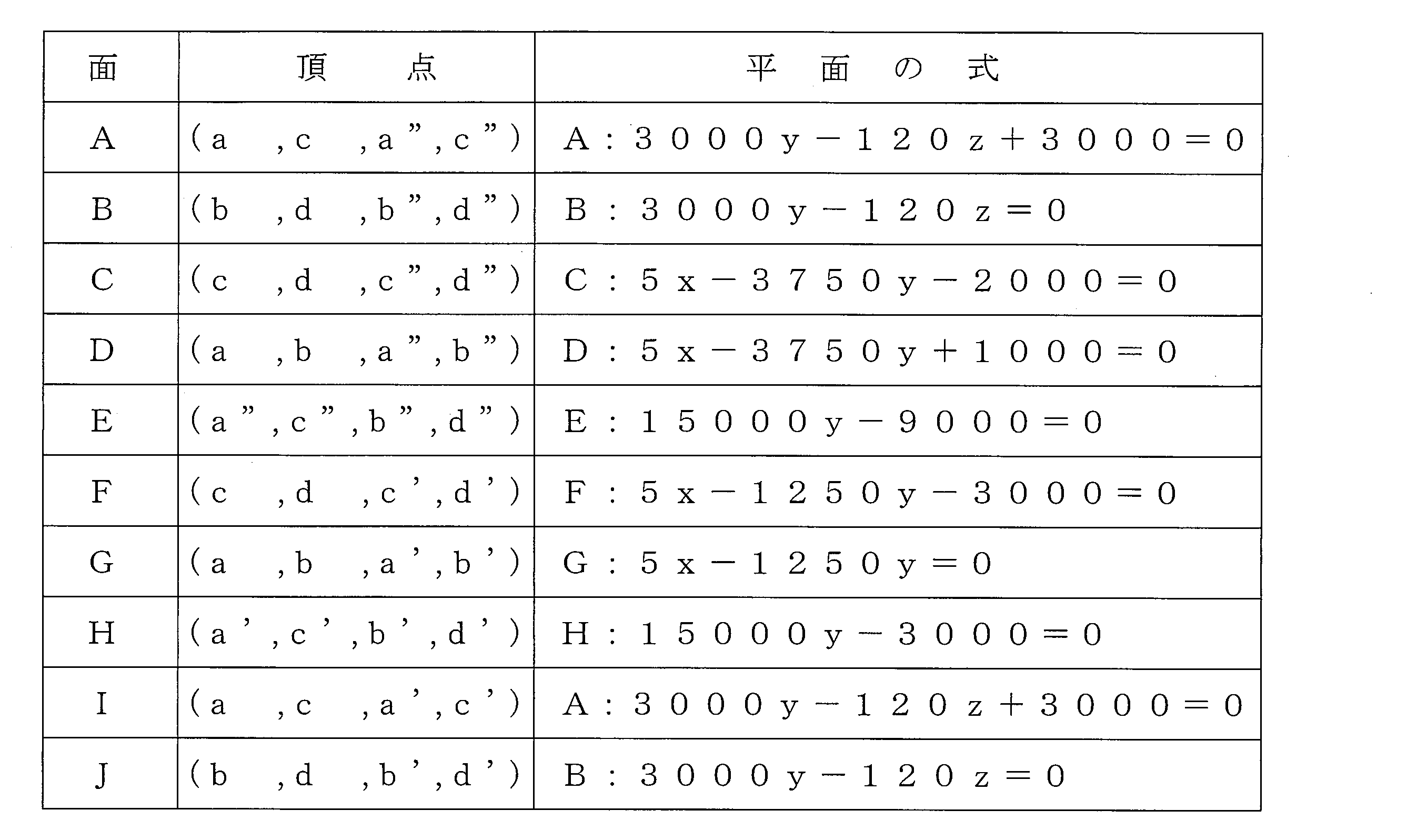
A面の式とI面の式は同じであるから、両者は同一平面であり、B面の式とJ面の式も同じであるから、両者は同一平面である。従って、図13に示す多面体はA面~H面の計8つの平面で囲まれた八面体であるということができる。また、この八面体では、C面とF面は凹稜角を形成し、D面とG面は凸稜角を形成している。
Since the formula for the A plane and the formula for the I plane are the same, they are the same plane, and the formula for the B plane and the formula for the J plane are the same, so both are the same plane. Therefore, it can be said that the polyhedron shown in FIG. 13 is an octahedron surrounded by a total of eight planes of A plane to H plane. Further, in this octahedron, the C surface and the F surface form a concave ridge angle, and the D surface and the G surface form a convex ridge angle.
すなわち、図13に示す多面体は、表1に示す8つの式A~Hで各々表される平面で囲まれ、且つ式Cで表される面と式Fで表される面が凹稜角を形成し、式Dで表される面と式Gで表される面が凸稜角を形成する八面体であるということができる。そして、Y(10゜)、係数k及び着色材濃度Cが、当該八面体で区画される範囲内に座標(Y(10゜),k,C)が存するという条件を満足する関係にあるとき、FI値が30以上となる。
That is, the polyhedron shown in FIG. 13 is surrounded by the planes represented by eight formulas A to H shown in Table 1, and the plane represented by formula C and the plane represented by formula F form a concave ridge angle. And it can be said that the surface represented by Formula D and the surface represented by Formula G are octahedrons that form convex ridge angles. When Y (10 °), the coefficient k, and the colorant concentration C satisfy the condition that the coordinates (Y (10 °), k, C) exist within the range defined by the octahedron. , The FI value is 30 or more.
次に、Y(10゜)、係数k及び着色材濃度Cに関し、FI値が35以上となる範囲も、図14に示すように、当該Y(10゜)、k及びCの3つの変数をx、y及びzの各座標軸におく上記三次元直交座標空間で表すことができる。すなわち、この多面体の図形は、上記頂点e~h、e’~h’及びe”~h”を三次元直交座標空間に配置して形成したものであり、表2に示す各々4つの頂点を含む合計10個の平面A’~J’で囲まれている。上記10個の平面の式は表6のようになる。
Next, with respect to Y (10 °), coefficient k, and colorant concentration C, the range in which the FI value is 35 or more is also represented by the three variables Y (10 °), k, and C as shown in FIG. It can be expressed by the three-dimensional orthogonal coordinate space placed on the x, y, and z coordinate axes. That is, this polyhedron figure is formed by arranging the vertices e to h, e 'to h' and e "to h" in a three-dimensional orthogonal coordinate space, and each of the four vertices shown in Table 2 is formed. A total of 10 planes A ′ to J ′ are included. Table 10 shows the above 10 plane equations.

A’面の式とI’面の式は同じであるから、両者は同一平面であり、B’面の式とK’面の式も同じであるから、両者は同一平面である。従って、図14に示す多面体はA’面~H’面の計8つの平面で囲まれた八面体であるということができる。また、この八面体では、C’面とF’面は凹稜角を形成し、D’面とG’面は凸稜角を形成している。
Since the formula of the A ′ plane and the formula of the I ′ plane are the same, they are the same plane, and the formula of the B ′ plane and the formula of the K ′ plane are also the same, so both are the same plane. Therefore, it can be said that the polyhedron shown in FIG. 14 is an octahedron surrounded by a total of eight planes from the A ′ plane to the H ′ plane. In this octahedron, the C ′ plane and the F ′ plane form a concave ridge angle, and the D ′ plane and the G ′ plane form a convex ridge angle.
すなわち、図14に示す多面体は、表2に示す8つの式A’~H’で各々表される平面で囲まれ、且つ式C’で表される面と式F’で表される面が凹稜角を形成し、式D’で表される面と式G’で表される面が凸稜角を形成する八面体であるということができる。そして、Y(10゜)、係数k及び着色材濃度Cが、当該八面体で区画される範囲内に座標(Y(10゜),k,C)が存するという条件を満足する関係にあるとき、FI値が35以上となる。
That is, the polyhedron shown in FIG. 14 is surrounded by the planes represented by the eight formulas A ′ to H ′ shown in Table 2, and the plane represented by the formula C ′ and the plane represented by the formula F ′ are It can be said that the concave ridge angle is formed, and the surface represented by the formula D ′ and the surface represented by the formula G ′ are octahedrons forming the convex ridge angle. When Y (10 °), the coefficient k, and the colorant concentration C satisfy the condition that the coordinates (Y (10 °), k, C) exist within the range defined by the octahedron. , The FI value is 35 or more.
ここに、FI値が30以上となるようにY(10゜)、係数k及び着色材濃度Cを設定したときの光輝材含有層の着色材を含有する状態でのY(10゜)は50以上200以下程度となり、係数k(=Y(20゜)/Y(10゜))は0.1以上0.4以下程度になる。
Here, when Y (10 °), the coefficient k, and the colorant concentration C are set so that the FI value is 30 or more, Y (10 °) in the state containing the colorant of the glittering material-containing layer is 50. The coefficient k (= Y (20 °) / Y (10 °)) is about 0.1 to about 0.4.
11 車体(鋼板)
12 積層塗膜
13 電着塗膜
14 着色下地層
15 光輝材含有層
16 透明クリヤ層
21 顔料(着色材)
22 光輝材
23 顔料(着色材) 11 Car body (steel plate)
DESCRIPTION OFSYMBOLS 12 Laminated coating film 13 Electrodeposition coating film 14 Colored underlayer 15 Bright material containing layer 16 Transparent clear layer 21 Pigment (coloring material)
22luster material 23 pigment (coloring material)
12 積層塗膜
13 電着塗膜
14 着色下地層
15 光輝材含有層
16 透明クリヤ層
21 顔料(着色材)
22 光輝材
23 顔料(着色材) 11 Car body (steel plate)
DESCRIPTION OF
22
Claims (8)
- 被塗物の表面に直接又は間接的に形成された着色材を含有する着色下地層と、該着色下地層の上に重ねられた、フレーク状光輝材及び着色材を含有する光輝材含有層とを備え、
上記光輝材含有層の上記着色材を含まない状態でのXYZ表色系の標準白色板で校正したY値に関して、受光角(正反射方向から光源側への傾き角度)10゜で測定した反射光のY値をY(10゜)とし、受光角20゜で測定した反射光のY値をY(20゜)とし、上記光輝材含有層の着色材濃度Cを質量百分率で表すとき、
Y(20゜)=k×Y(10゜)であり(但し、kは係数である。)、
上記Y(10゜)、k及びCは、このY(10゜)、k及びCの3つの変数をx、y及びzの各座標軸におく三次元直交座標空間において、座標(Y(10゜),k,C)が、次の8つの式A~Hで各々表される平面で囲まれ、且つ式Cで表される面と式Fで表される面が凹稜角を形成し、式Dで表される面と式Gで表される面が凸稜角を形成する八面体で区画される範囲内に存するという条件を満足する関係にあり、
式A:3000y-120z+3000=0
式B:3000y-120z=0
式C:5x-3750y-2000=0
式D:5x-3750y+1000=0
式E:15000y-9000=0
式F:5x-1250y-3000=0
式G:5x-1250y=0
式H:15000y-3000=0
上記着色下地層の可視光線の表面反射率R(%)が、上記光輝材含有層のY(10゜)及び着色材濃度Cを用いた次式の条件を満足することを特徴とする積層塗膜。
R≦0.6×C+0.04×Y(10゜)+4 A colored underlayer containing a coloring material formed directly or indirectly on the surface of the object to be coated, and a bright material-containing layer containing a flake-like glittering material and a coloring material, which are superimposed on the colored underlayer With
Reflection measured at a light receiving angle (tilt angle from the regular reflection direction to the light source side) at 10 ° with respect to the Y value calibrated with the standard white plate of the XYZ color system in the state where the coloring material is not included in the glittering material-containing layer. When the Y value of light is Y (10 °), the Y value of reflected light measured at a light receiving angle of 20 ° is Y (20 °), and the colorant concentration C of the glittering material-containing layer is expressed by mass percentage,
Y (20 °) = k × Y (10 °) (where k is a coefficient),
Y (10 °), k, and C are coordinates (Y (10 °) in a three-dimensional orthogonal coordinate space in which the three variables Y (10 °), k, and C are set on the x, y, and z coordinate axes. ), K, C) are surrounded by the planes represented by the following eight formulas A to H, respectively, and the surface represented by the formula C and the plane represented by the formula F form a concave ridge angle. The surface represented by D and the surface represented by the formula G are in a relationship satisfying the condition that they exist within a range defined by an octahedron that forms a convex ridge angle,
Formula A: 3000y-120z + 3000 = 0
Formula B: 3000y-120z = 0
Formula C: 5x-3750y-2000 = 0
Formula D: 5x-3750y + 1000 = 0
Formula E: 15000y-9000 = 0
Formula F: 5x-1250y-3000 = 0
Formula G: 5x-1250y = 0
Formula H: 15000y-3000 = 0
A laminate coating characterized in that the visible light surface reflectance R (%) of the colored underlayer satisfies the following formula using Y (10 °) and the coloring material concentration C of the glittering material-containing layer: film.
R ≦ 0.6 × C + 0.04 × Y (10 °) +4 - 請求項1において、
上記光輝材がアルミフレークであり、その厚さが25nm以上200nm以下であることを特徴とする積層塗膜。 In claim 1,
The above-mentioned glittering material is aluminum flakes, and the thickness thereof is 25 nm or more and 200 nm or less. - 請求項2において、
上記光輝材含有層の表面に対する上記アルミフレークの配向角が3度以下であることを特徴とする積層塗膜。 In claim 2,
A laminated coating film, wherein an orientation angle of the aluminum flake relative to the surface of the glittering material-containing layer is 3 degrees or less. - 請求項1乃至請求項3のいずれか一において、
上記着色下地層及び光輝材含有層各々の着色材が濃色系であることを特徴とする積層塗膜。 In any one of Claim 1 thru | or 3,
A laminated coating film, wherein the coloring material of each of the colored underlayer and the glittering material-containing layer is a dark color system. - 請求項4において、
上記着色下地層の着色材と上記光輝材含有層の着色材が同色系であることを特徴とする積層塗膜。 In claim 4,
A laminated coating film, wherein the coloring material of the colored underlayer and the coloring material of the glittering material-containing layer are of the same color system. - 請求項5において、
上記着色下地層及び光輝材含有層各々の着色材が黒色系であることを特徴とする積層塗膜。 In claim 5,
A laminated coating film, wherein the coloring material of each of the colored base layer and the glittering material-containing layer is black. - 請求項1乃至請求項6のいずれか一において、
上記光輝材含有層の上に透明クリヤ層が直接積層されていることを特徴とする積層塗膜。 In any one of Claims 1 thru | or 6,
A laminated coating film, wherein a transparent clear layer is directly laminated on the glittering material-containing layer. - 請求項1乃至請求項7のいずれか一に記載された積層塗膜を備えていることを特徴とする塗装物。 A coated article comprising the laminated coating film according to any one of claims 1 to 7.
Priority Applications (5)
| Application Number | Priority Date | Filing Date | Title |
|---|---|---|---|
| CN201880008246.XA CN110214082B (en) | 2017-01-25 | 2018-01-23 | Multilayer coating film and coated article |
| RU2019126723A RU2725940C1 (en) | 2017-01-25 | 2018-01-23 | Multilayer coating film and article with coating |
| MX2019008858A MX2019008858A (en) | 2017-01-25 | 2018-01-23 | Multilayer coating film and coated object. |
| US16/479,889 US20200353505A1 (en) | 2017-01-25 | 2018-01-23 | Multilayered coating film and coated object |
| EP18744833.7A EP3560706A4 (en) | 2017-01-25 | 2018-01-23 | Multilayer coating film and coated object |
Applications Claiming Priority (2)
| Application Number | Priority Date | Filing Date | Title |
|---|---|---|---|
| JP2017-011271 | 2017-01-25 | ||
| JP2017011271A JP6468296B2 (en) | 2017-01-25 | 2017-01-25 | Laminated coatings and painted products |
Publications (1)
| Publication Number | Publication Date |
|---|---|
| WO2018139429A1 true WO2018139429A1 (en) | 2018-08-02 |
Family
ID=62978911
Family Applications (1)
| Application Number | Title | Priority Date | Filing Date |
|---|---|---|---|
| PCT/JP2018/001905 WO2018139429A1 (en) | 2017-01-25 | 2018-01-23 | Multilayer coating film and coated object |
Country Status (7)
| Country | Link |
|---|---|
| US (1) | US20200353505A1 (en) |
| EP (1) | EP3560706A4 (en) |
| JP (1) | JP6468296B2 (en) |
| CN (1) | CN110214082B (en) |
| MX (1) | MX2019008858A (en) |
| RU (1) | RU2725940C1 (en) |
| WO (1) | WO2018139429A1 (en) |
Cited By (3)
| Publication number | Priority date | Publication date | Assignee | Title |
|---|---|---|---|---|
| WO2022102380A1 (en) * | 2020-11-13 | 2022-05-19 | マツダ株式会社 | Multilayered coating film and coated article |
| WO2022102378A1 (en) * | 2020-11-13 | 2022-05-19 | マツダ株式会社 | Multilayered coating film and coated article |
| WO2022102379A1 (en) * | 2020-11-13 | 2022-05-19 | マツダ株式会社 | Multilayered coating film and coated article |
Citations (9)
| Publication number | Priority date | Publication date | Assignee | Title |
|---|---|---|---|---|
| JPH10192776A (en) | 1997-01-13 | 1998-07-28 | Kansai Paint Co Ltd | Formation of double layer coating film |
| JP2005144338A (en) * | 2003-11-17 | 2005-06-09 | Kansai Paint Co Ltd | Coating method |
| JP2005200519A (en) | 2004-01-15 | 2005-07-28 | Basf Coatings Japan Ltd | Metallic coating composition, coating film forming method, and coated article |
| JP2010030075A (en) | 2008-07-25 | 2010-02-12 | Toyoda Gosei Co Ltd | Electromagnetic wave transmissive brilliant coating resin product and its manufacturing method |
| JP2011020021A (en) * | 2009-07-14 | 2011-02-03 | Kansai Paint Co Ltd | Coating film forming method |
| JP2012011302A (en) * | 2010-06-30 | 2012-01-19 | Nippon Paint Co Ltd | Method for forming multilayer coating film |
| JP2013169507A (en) * | 2012-02-21 | 2013-09-02 | Kansai Paint Co Ltd | Coating film forming method |
| WO2016088294A1 (en) * | 2014-12-02 | 2016-06-09 | マツダ株式会社 | Multilayer coating film and coated object |
| WO2017006529A1 (en) * | 2015-07-08 | 2017-01-12 | マツダ株式会社 | Multilayer coating film and coated article |
Family Cites Families (4)
| Publication number | Priority date | Publication date | Assignee | Title |
|---|---|---|---|---|
| JP2000000514A (en) * | 1998-06-16 | 2000-01-07 | Kansai Paint Co Ltd | Metallic coat formation |
| JP2006181505A (en) * | 2004-12-28 | 2006-07-13 | Nissan Motor Co Ltd | Metallic coating method and laminated coating film |
| JP2011162732A (en) * | 2010-02-15 | 2011-08-25 | Kansai Paint Co Ltd | Metallic paint composition and method of forming paint film |
| JP2011251253A (en) * | 2010-06-02 | 2011-12-15 | Nippon Paint Co Ltd | Method of forming multilayer coating film |
-
2017
- 2017-01-25 JP JP2017011271A patent/JP6468296B2/en active Active
-
2018
- 2018-01-23 US US16/479,889 patent/US20200353505A1/en not_active Abandoned
- 2018-01-23 RU RU2019126723A patent/RU2725940C1/en active
- 2018-01-23 EP EP18744833.7A patent/EP3560706A4/en not_active Withdrawn
- 2018-01-23 CN CN201880008246.XA patent/CN110214082B/en active Active
- 2018-01-23 MX MX2019008858A patent/MX2019008858A/en unknown
- 2018-01-23 WO PCT/JP2018/001905 patent/WO2018139429A1/en unknown
Patent Citations (9)
| Publication number | Priority date | Publication date | Assignee | Title |
|---|---|---|---|---|
| JPH10192776A (en) | 1997-01-13 | 1998-07-28 | Kansai Paint Co Ltd | Formation of double layer coating film |
| JP2005144338A (en) * | 2003-11-17 | 2005-06-09 | Kansai Paint Co Ltd | Coating method |
| JP2005200519A (en) | 2004-01-15 | 2005-07-28 | Basf Coatings Japan Ltd | Metallic coating composition, coating film forming method, and coated article |
| JP2010030075A (en) | 2008-07-25 | 2010-02-12 | Toyoda Gosei Co Ltd | Electromagnetic wave transmissive brilliant coating resin product and its manufacturing method |
| JP2011020021A (en) * | 2009-07-14 | 2011-02-03 | Kansai Paint Co Ltd | Coating film forming method |
| JP2012011302A (en) * | 2010-06-30 | 2012-01-19 | Nippon Paint Co Ltd | Method for forming multilayer coating film |
| JP2013169507A (en) * | 2012-02-21 | 2013-09-02 | Kansai Paint Co Ltd | Coating film forming method |
| WO2016088294A1 (en) * | 2014-12-02 | 2016-06-09 | マツダ株式会社 | Multilayer coating film and coated object |
| WO2017006529A1 (en) * | 2015-07-08 | 2017-01-12 | マツダ株式会社 | Multilayer coating film and coated article |
Non-Patent Citations (1)
| Title |
|---|
| See also references of EP3560706A4 |
Cited By (3)
| Publication number | Priority date | Publication date | Assignee | Title |
|---|---|---|---|---|
| WO2022102380A1 (en) * | 2020-11-13 | 2022-05-19 | マツダ株式会社 | Multilayered coating film and coated article |
| WO2022102378A1 (en) * | 2020-11-13 | 2022-05-19 | マツダ株式会社 | Multilayered coating film and coated article |
| WO2022102379A1 (en) * | 2020-11-13 | 2022-05-19 | マツダ株式会社 | Multilayered coating film and coated article |
Also Published As
| Publication number | Publication date |
|---|---|
| EP3560706A1 (en) | 2019-10-30 |
| JP2018118437A (en) | 2018-08-02 |
| EP3560706A4 (en) | 2020-01-15 |
| CN110214082B (en) | 2022-03-22 |
| CN110214082A (en) | 2019-09-06 |
| US20200353505A1 (en) | 2020-11-12 |
| JP6468296B2 (en) | 2019-02-13 |
| RU2725940C1 (en) | 2020-07-07 |
| MX2019008858A (en) | 2019-09-11 |
Similar Documents
| Publication | Publication Date | Title |
|---|---|---|
| JP6330742B2 (en) | Laminate coating design method | |
| WO2017006530A1 (en) | Multilayer coating film and coated article | |
| JP6677315B2 (en) | Laminated coatings and painted objects | |
| JP6766875B2 (en) | Laminated coating film and painted material | |
| US20170218206A1 (en) | Multilayer coating film and coated object | |
| JP6677314B2 (en) | Laminated coatings and painted objects | |
| WO2018139429A1 (en) | Multilayer coating film and coated object |
Legal Events
| Date | Code | Title | Description |
|---|---|---|---|
| 121 | Ep: the epo has been informed by wipo that ep was designated in this application |
Ref document number: 18744833 Country of ref document: EP Kind code of ref document: A1 |
|
| NENP | Non-entry into the national phase |
Ref country code: DE |
|
| ENP | Entry into the national phase |
Ref document number: 2018744833 Country of ref document: EP Effective date: 20190726 |