WO2018131524A1 - Image processing device and image processing method - Google Patents
Image processing device and image processing method Download PDFInfo
- Publication number
- WO2018131524A1 WO2018131524A1 PCT/JP2017/047374 JP2017047374W WO2018131524A1 WO 2018131524 A1 WO2018131524 A1 WO 2018131524A1 JP 2017047374 W JP2017047374 W JP 2017047374W WO 2018131524 A1 WO2018131524 A1 WO 2018131524A1
- Authority
- WO
- WIPO (PCT)
- Prior art keywords
- tap
- class
- image
- unit
- coefficient
- Prior art date
Links
Images


Classifications
-
- H—ELECTRICITY
- H04—ELECTRIC COMMUNICATION TECHNIQUE
- H04N—PICTORIAL COMMUNICATION, e.g. TELEVISION
- H04N19/00—Methods or arrangements for coding, decoding, compressing or decompressing digital video signals
- H04N19/80—Details of filtering operations specially adapted for video compression, e.g. for pixel interpolation
- H04N19/82—Details of filtering operations specially adapted for video compression, e.g. for pixel interpolation involving filtering within a prediction loop
-
- H—ELECTRICITY
- H04—ELECTRIC COMMUNICATION TECHNIQUE
- H04N—PICTORIAL COMMUNICATION, e.g. TELEVISION
- H04N19/00—Methods or arrangements for coding, decoding, compressing or decompressing digital video signals
- H04N19/85—Methods or arrangements for coding, decoding, compressing or decompressing digital video signals using pre-processing or post-processing specially adapted for video compression
- H04N19/86—Methods or arrangements for coding, decoding, compressing or decompressing digital video signals using pre-processing or post-processing specially adapted for video compression involving reduction of coding artifacts, e.g. of blockiness
-
- H—ELECTRICITY
- H04—ELECTRIC COMMUNICATION TECHNIQUE
- H04N—PICTORIAL COMMUNICATION, e.g. TELEVISION
- H04N19/00—Methods or arrangements for coding, decoding, compressing or decompressing digital video signals
- H04N19/10—Methods or arrangements for coding, decoding, compressing or decompressing digital video signals using adaptive coding
- H04N19/102—Methods or arrangements for coding, decoding, compressing or decompressing digital video signals using adaptive coding characterised by the element, parameter or selection affected or controlled by the adaptive coding
- H04N19/117—Filters, e.g. for pre-processing or post-processing
-
- H—ELECTRICITY
- H04—ELECTRIC COMMUNICATION TECHNIQUE
- H04N—PICTORIAL COMMUNICATION, e.g. TELEVISION
- H04N19/00—Methods or arrangements for coding, decoding, compressing or decompressing digital video signals
- H04N19/10—Methods or arrangements for coding, decoding, compressing or decompressing digital video signals using adaptive coding
- H04N19/134—Methods or arrangements for coding, decoding, compressing or decompressing digital video signals using adaptive coding characterised by the element, parameter or criterion affecting or controlling the adaptive coding
- H04N19/136—Incoming video signal characteristics or properties
-
- H—ELECTRICITY
- H04—ELECTRIC COMMUNICATION TECHNIQUE
- H04N—PICTORIAL COMMUNICATION, e.g. TELEVISION
- H04N19/00—Methods or arrangements for coding, decoding, compressing or decompressing digital video signals
- H04N19/10—Methods or arrangements for coding, decoding, compressing or decompressing digital video signals using adaptive coding
- H04N19/169—Methods or arrangements for coding, decoding, compressing or decompressing digital video signals using adaptive coding characterised by the coding unit, i.e. the structural portion or semantic portion of the video signal being the object or the subject of the adaptive coding
- H04N19/182—Methods or arrangements for coding, decoding, compressing or decompressing digital video signals using adaptive coding characterised by the coding unit, i.e. the structural portion or semantic portion of the video signal being the object or the subject of the adaptive coding the unit being a pixel
-
- H—ELECTRICITY
- H04—ELECTRIC COMMUNICATION TECHNIQUE
- H04N—PICTORIAL COMMUNICATION, e.g. TELEVISION
- H04N19/00—Methods or arrangements for coding, decoding, compressing or decompressing digital video signals
- H04N19/46—Embedding additional information in the video signal during the compression process
Definitions
- the present technology relates to an image processing apparatus and an image processing method, and more particularly, to an image processing apparatus and an image processing method capable of greatly improving, for example, an image S / N.
- HEVC High Efficiency Video Coding
- ILF In Loop Filter
- post-HEVC predictive coding scheme of the next generation of HEVC
- ILF includes DF (Deblocking Filter) to reduce block noise, SAO (Sample Adaptive Offset) to reduce ringing, and ALF to minimize coding error (error of decoded image with respect to original image). (Adaptive Loop Filter).
- ALF is described in Patent Document 1
- SAO is described in Patent Document 2.
- the currently proposed DF, SAO, and ALF as ILFs have a low degree of freedom and it is difficult to perform fine filter control, so the S / N (Signal to Noise Ratio) of the image is greatly improved. Is difficult.
- the present technology has been made in view of such a situation, and makes it possible to greatly improve the S / N of an image.
- An image processing apparatus is configured to classify a processing target pixel of a first image obtained by adding a prediction encoding residual and a prediction image into one of a plurality of classes.
- a class tap selection unit that configures the class tap by selecting a pixel to be used as a class tap from the first image, and a class that classifies the processing target pixel using the class tap.
- a class tap, and a class processing unit that performs a filtering process corresponding to the class of the processing target pixel on the first image and generates a second image used for prediction of the predicted image.
- the selection unit is an image processing device that updates the tap structure of the class tap to a tap structure selected from a plurality of tap structures.
- An image processing method of the present technology is a class classification that classifies a processing target pixel of a first image obtained by adding a residual of prediction encoding and a prediction image into one of a plurality of classes. Configuring the class tap by selecting a pixel to be used as a class tap from the first image, classifying the processing target pixel using the class tap, and Filtering the first image corresponding to the class of the processing target pixel to generate a second image used for prediction of the predicted image, wherein the tap structure of the class tap includes a plurality of tap structures.
- This is an image processing method for updating to a tap structure selected from the tap structures.
- the processing target pixel of the first image obtained by adding the prediction encoding residual and the prediction image is set to any one of a plurality of classes.
- the class tap is configured by selecting, from the first image, a pixel to be a class tap used for class classification.
- the class tap is used to classify the processing target pixel, and the first image is subjected to filter processing corresponding to the class of the processing target pixel, and used for prediction of the predicted image.
- a second image to be generated is generated.
- the tap structure of the class tap is updated to a tap structure selected from a plurality of tap structures.
- the image processing apparatus may be an independent apparatus or an internal block constituting one apparatus.
- the image processing apparatus can be realized by causing a computer to execute a program.
- the program can be provided by being transmitted through a transmission medium or by being recorded on a recording medium.
- the S / N of the image can be greatly improved.
- FIG. 3 is a block diagram illustrating a configuration example of a learning unit 33.
- FIG. It is a block diagram which shows the 2nd structural example of the image converter which performs a classification classification adaptive process. It is a block diagram which shows the structural example of the learning apparatus which learns the seed coefficient memorize
- FIG. 10 is a block diagram illustrating another configuration example of a learning unit 63.
- FIG. 3 is a block diagram illustrating a first configuration example of an encoding device 11.
- FIG. 3 is a block diagram illustrating a configuration example of a class classification adaptive filter 111.
- FIG. 3 is a block diagram illustrating a configuration example of a learning device 131.
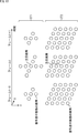
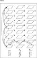
- FIG. It is a figure which shows the example of the class tap shape as a tap structure of a class tap. It is a figure which shows the example of the tap structure of the class tap comprised from the pixel of several frames. It is a figure which shows the example of the variation of the tap structure of a class tap.
- FIG. 12 is a flowchart illustrating an example of processing of the learning device 131.
- 3 is a block diagram illustrating a configuration example of an image conversion apparatus 133.
- FIG. 12 is a flowchart illustrating an example of encoding processing of the encoding device 11. It is a flowchart explaining the example of the class classification adaptation process performed by step S46.
- FIG. 3 is a block diagram illustrating a first configuration example of a decoding device 12.
- FIG. 3 is a block diagram illustrating a configuration example of a class classification adaptive filter 206.
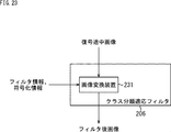
- FIG. 3 is a block diagram illustrating a configuration example of an image conversion apparatus 231.
- FIG. 12 is a flowchart illustrating an example of a decoding process of the decoding device 12. It is a flowchart explaining the example of the class classification adaptation process performed by step S122. It is a figure explaining the example of the reduction method which reduces the tap coefficient for every class.
- 3 is a block diagram illustrating a second configuration example of the encoding device 11.
- FIG. 3 is a block diagram illustrating a configuration example of a class classification adaptive filter 311.
- FIG. 3 is a block diagram illustrating a configuration example of a learning device 331.
- FIG. 3 is a block diagram illustrating a configuration example of an image conversion unit 371.
- FIG. 10 is a flowchart illustrating an example of processing of a learning device 331.
- 3 is a block diagram illustrating a configuration example of an image conversion apparatus 333.
- FIG. 12 is a flowchart illustrating an example of encoding processing of the encoding device 11. It is a flowchart explaining the example of the class classification adaptation process performed by step S246.
- 12 is a block diagram illustrating a second configuration example of the decoding device 12.
- FIG. 1 is a block diagram illustrating a configuration example of a learning device 331.
- FIG. 3 is a block diagram illustrating a configuration example of an image conversion unit 371.
- FIG. 10 is a flowchart illustrating an example of processing of a learning device 331.
- 3 is a block diagram illustrating a configuration example of an image conversion apparatus
- FIG. 3 is a block diagram illustrating a configuration example of a class classification adaptive filter 401.
- FIG. 3 is a block diagram illustrating a configuration example of an image conversion apparatus 431.
- FIG. 12 is a flowchart illustrating an example of a decoding process of the decoding device 12. It is a flowchart explaining the example of the class classification adaptation process performed by step S322. It is a figure which shows the example of a multiview image encoding system. It is a figure which shows the main structural examples of the multiview image coding apparatus to which this technique is applied. It is a figure which shows the main structural examples of the multiview image decoding apparatus to which this technique is applied. It is a figure which shows the example of a hierarchy image coding system.
- FIG. 20 is a block diagram illustrating a main configuration example of a computer. It is a block diagram which shows an example of a schematic structure of a television apparatus. It is a block diagram which shows an example of a schematic structure of a mobile telephone. It is a block diagram which shows an example of a schematic structure of a recording / reproducing apparatus. It is a block diagram which shows an example of a schematic structure of an imaging device. It is a block diagram which shows an example of a schematic structure of a video set. It is a block diagram which shows an example of a schematic structure of a video processor. It is a block diagram which shows the other example of the schematic structure of a video processor.
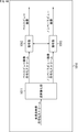
- FIG. 1 is a diagram illustrating a configuration example of an embodiment of an image processing system to which the present technology is applied.
- the image processing system includes an encoding device 11 and a decoding device 12.
- the original image to be encoded is supplied to the encoding device 11.
- the encoding device 11 encodes the original image by predictive encoding such as HEVC or AVC (Advanced Video Coding).
- predictive encoding such as HEVC or AVC (Advanced Video Coding).
- a predicted image of the original image is generated, and the residual between the original image and the predicted image is encoded.
- an ILF process is performed by applying ILF to a decoding intermediate image obtained by adding the residual of predictive encoding and the predictive image, and is used for prediction of the predictive image.
- a reference image to be generated is generated.
- an image obtained by performing filter processing (filtering) as ILF processing on an image in the middle of decoding is also referred to as a post-filter image.
- the encoding device 11 performs ILF processing such that the filtered image is as close to the original image as possible by performing learning or the like using the intermediate decoding image and the original image as necessary.
- the information regarding the filtering process can be obtained as filter information.
- the ILF processing of the encoding device 11 can be performed using filter information obtained by learning.
- learning for obtaining filter information is performed, for example, for each sequence of one or a plurality of original images, or for one or a plurality of scenes (frames from a scene change to the next scene change) of the original image. Alternatively, it can be performed for each of a plurality of frames (pictures), for each of one or a plurality of slices of the original image, for one or a plurality of lines of a block of a unit for encoding a picture, or any other unit.
- the learning for obtaining the filter information can be performed, for example, when the residual becomes equal to or greater than a threshold value.
- the encoding device 11 transmits the encoded data obtained by predictive encoding of the original image via the transmission medium 13 or transmits to the recording medium 14 for recording.
- the encoding device 11 can transmit the filter information obtained by learning through the transmission medium 13 or transmit it to the recording medium 14 for recording.
- learning for obtaining filter information can be performed by a device different from the encoding device 11.
- the filter information can be transmitted separately from the encoded data, or can be transmitted by being included in the encoded data.
- the learning for obtaining the filter information is performed using the original image itself (and the decoding intermediate image obtained from the original image), or using an image that is similar to the original image and that is different from the original image. be able to.
- the decoding device 12 receives (receives) (acquires) the encoded data transmitted from the encoding device 11 and necessary filter information via the transmission medium 13 and the recording medium 14, and encodes the encoded data. Decoding is performed by a method corresponding to the predictive coding of the apparatus 11.
- the decoding device 12 processes the encoded data from the encoding device 11 to obtain a prediction encoding residual. Furthermore, the decoding device 12 obtains a decoding intermediate image similar to that obtained by the encoding device 11 by adding the residual and the predicted image. Then, the decoding device 12 performs a filtering process as an ILF process using the filter information from the encoding device 11 as necessary on the decoding-in-progress image to obtain a filtered image.
- the filtered image is output as a decoded image of the original image, and is temporarily stored as a reference image used for prediction of the predicted image as necessary.
- the filter processing as the ILF processing of the encoding device 11 and the decoding device 12 can be performed by an arbitrary filter.
- the filter processing of the encoding device 11 and the decoding device 12 can be performed by class classification adaptive processing (prediction calculation thereof).
- class classification adaptive processing prediction calculation thereof
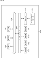
- FIG. 2 is a block diagram illustrating a first configuration example of an image conversion apparatus that performs class classification adaptation processing.
- the class classification adaptation process can be understood as, for example, an image conversion process for converting a first image into a second image.
- the image conversion processing for converting the first image into the second image is various signal processing depending on the definition of the first and second images.
- the image conversion process is a spatial resolution creation (improvement) process that improves the spatial resolution. be able to.
- the image conversion process can be referred to as a noise removal process for removing noise.
- the image conversion process is performed as follows: This can be referred to as resizing processing for resizing (enlarging or reducing) an image.
- the first image is a decoded image obtained by decoding an image encoded in block units such as HEVC
- the second image is an original image before encoding
- the image conversion process can be referred to as a distortion removal process that removes block distortion caused by encoding and decoding in units of blocks.
- the classification classification adaptive processing can be performed on, for example, sound as well as images.
- the classification classification adaptation process for sound is a sound conversion process for converting the first sound (for example, sound with low S / N) into the second sound (for example, sound with high S / N). Can be caught.
- the pixel value of the target pixel is obtained by a prediction calculation using the tap coefficient and the pixel values of the same number of pixels as the tap coefficient of the first image selected for the target pixel.
- FIG. 2 shows a configuration example of an image conversion apparatus that performs image conversion processing by class classification adaptive processing.
- the image conversion apparatus 20 includes tap selection units 21 and 22, a class classification unit 23, a coefficient acquisition unit 24, and a prediction calculation unit 25.
- the first image is supplied to the image conversion device 20.
- the first image supplied to the image conversion device 20 is supplied to the tap selection units 21 and 22.
- the tap selection unit 21 sequentially selects the pixels constituting the first image as the target pixel. Further, the tap selection unit 21 predicts some of the pixels (the pixel values) constituting the first image used to predict the corresponding pixels (the pixel values) of the second image corresponding to the target pixel. Select as a tap.
- the tap selection unit 21 selects, as prediction taps, a plurality of pixels of the first image that are spatially or temporally close to the temporal and spatial positions of the target pixel.
- the tap selection unit 22 classifies some of the pixels (pixel values) constituting the first image used for classifying the target pixel into any of several classes. Choose as. That is, the tap selection unit 22 selects a class tap in the same manner as the tap selection unit 21 selects a prediction tap.
- prediction tap and the class tap may have the same tap structure or may have different tap structures.
- the prediction tap obtained by the tap selection unit 21 is supplied to the prediction calculation unit 25, and the class tap obtained by the tap selection unit 22 is supplied to the class classification unit 23.
- the class classification unit 23 classifies the target pixel according to a certain rule, and supplies a class code corresponding to the class obtained as a result to the coefficient acquisition unit 24.
- the class classification unit 23 classifies the target pixel using, for example, the class tap from the tap selection unit 22 and supplies a class code corresponding to the class obtained as a result to the coefficient acquisition unit 24.
- the class classification unit 23 obtains the image feature amount of the target pixel using the class tap. Further, the class classification unit 23 classifies the target pixel according to the image feature amount of the target pixel, and supplies a class code corresponding to the class obtained as a result to the coefficient acquisition unit 24.
- ADRC Adaptive Dynamic Range Coding
- pixels (pixel values) constituting the class tap are subjected to ADRC processing, and the class of the pixel of interest is determined according to the ADRC code (ADRC value) obtained as a result.
- the ADRC code represents a waveform pattern as an image feature amount of a small area including the target pixel.
- the pixel value of each pixel constituting the class tap is requantized to L bits. That is, the pixel value of each pixel forming the class taps, the minimum value MIN is subtracted, and the subtracted value is divided by DR / 2 L (requantization).
- a bit string obtained by arranging the pixel values of the L-bit pixels constituting the class tap in a predetermined order, which is obtained as described above, is output as an ADRC code.
- the pixel value of each pixel constituting the class tap is divided by the average value of the maximum value MAX and the minimum value MIN (rounded down). Thereby, the pixel value of each pixel is set to 1 bit (binarized). Then, a bit string in which the 1-bit pixel values are arranged in a predetermined order is output as an ADRC code.
- the level distribution pattern of the pixel values of the pixels constituting the class tap can be directly output to the class classification unit 23 as a class code.
- the class tap is composed of pixel values of N pixels, and the A bit is assigned to the pixel value of each pixel, the number of class codes output by the class classification unit 23 Is (2 N ) A , which is an enormous number that is exponentially proportional to the number of bits A of the pixel value of the pixel.
- the class classification unit 23 preferably performs class classification by compressing the information amount of the class tap by the above-described ADRC processing or vector quantization.
- the coefficient acquisition unit 24 stores the tap coefficient for each class obtained by learning described later, and further, among the stored tap coefficients, the tap coefficient of the class represented by the class code supplied from the class classification unit 23, That is, the tap coefficient of the class of the target pixel is acquired. Further, the coefficient acquisition unit 24 supplies the tap coefficient of the class of the target pixel to the prediction calculation unit 25.
- the tap coefficient is a coefficient corresponding to a coefficient multiplied with input data in a so-called tap in a digital filter.
- the prediction calculation unit 25 uses the prediction tap output from the tap selection unit 21 and the tap coefficient supplied from the coefficient acquisition unit 24, and the pixel value of the pixel (corresponding pixel) of the second image corresponding to the target pixel. A predetermined prediction calculation for obtaining a predicted value of the true value of is performed. Thereby, the prediction calculation unit 25 obtains and outputs the pixel value of the corresponding pixel (predicted value thereof), that is, the pixel value of the pixels constituting the second image.
- FIG. 3 is a block diagram illustrating a configuration example of a learning device that performs learning of tap coefficients stored in the coefficient acquisition unit 24.
- a high-quality image (high-quality image) is used as the second image, and the high-quality image is filtered by LPF (Low Pass Filter) to reduce the image quality (resolution).
- LPF Low Pass Filter
- the pixel value y of the high-quality pixel is obtained by the following linear primary expression.
- x n represents a pixel value of an n-th low-quality image pixel (hereinafter referred to as a low-quality pixel as appropriate) that constitutes a prediction tap for the high-quality pixel y as the corresponding pixel.
- W n represent the n th tap coefficient to be multiplied by the n th low image quality pixel (its pixel value).
- the pixel value y of the high-quality pixel can be obtained not by the linear primary expression shown in Expression (1) but by a higher-order expression of the second or higher order.
- x n, k represents the n-th low-quality pixel constituting the prediction tap for the high-quality pixel of the k-th sample as the corresponding pixel.
- Tap coefficient w n for the prediction error e k 0 of the formula (3) (or Equation (2)) is, is the optimal for predicting the high-quality pixel, for all the high-quality pixel, such In general, it is difficult to obtain a simple tap coefficient w n .
- the optimal tap coefficient w n is the sum of square errors E ( It can be obtained by minimizing (statistical error).
- K is a high-quality pixel y k as a corresponding pixel and low-quality pixels x 1, k , x 2, k ,... Constituting a prediction tap for the high-quality pixel y k .
- X N, k represents the number of samples (number of learning samples).
- Equation (5) The minimum value of the sum E of square errors of Equation (4) (minimum value), as shown in Equation (5), given that by partially differentiating the sum E with the tap coefficient w n by w n to 0.
- equation (7) can be expressed by the normal equation shown in equation (8).
- Equation (8) by solving for each class, the optimal tap coefficient (here, the tap coefficient that minimizes the sum E of square errors) to w n, can be found for each class .
- Figure 3 shows an example of the configuration of a learning apparatus that performs learning for determining the tap coefficient w n by solving the normal equations in equation (8).
- the learning device 30 includes a teacher data generation unit 31, a student data generation unit 32, and a learning unit 33.
- the tutor data generating unit 31 and student data generating unit 32 the learning image used for learning of the tap coefficient w n is supplied.
- the learning image for example, a high-quality image with high resolution can be used.
- the teacher data generation unit 31 uses the learning image as the teacher data that becomes the teacher (true value) for learning the tap coefficient, that is, the teacher data that is to be obtained by the class classification adaptation process, and the mapping of the mapping as a prediction calculation according to Expression (1).
- a teacher image as a mapping destination is generated and supplied to the learning unit 33.
- the teacher data generation unit 31 supplies a high-quality image as a learning image to the learning unit 33 as it is as a teacher image.
- the student data generation unit 32 uses the learning image as the student data to be a student of tap coefficient learning, that is, as the student data to be subjected to the prediction calculation with the tap coefficient in the class classification adaptation process, the prediction calculation according to Expression (1).
- a student image to be converted by the mapping is generated and supplied to the learning unit 33.
- the student data generation unit 32 generates a low-quality image by, for example, filtering a high-quality image as a learning image with an LPF (low-pass filter) to reduce the resolution, thereby generating the low-quality image.
- the image is supplied to the learning unit 33 as a student image.
- the learning unit 33 sequentially sets the pixels constituting the student image as the student data from the student data generation unit 32 as the target pixel, and the same tap as the tap selection unit 21 of FIG. 2 selects for the target pixel.
- a pixel of the structure is selected as a prediction tap from the student image.
- the learning unit 33 uses the corresponding pixels constituting the teacher image corresponding to the target pixel and the prediction tap of the target pixel, and for each class, establishes a normal equation of Equation (8) and solves the class.
- the tap coefficient for each is obtained.
- FIG. 4 is a block diagram illustrating a configuration example of the learning unit 33 in FIG.
- the learning unit 33 includes tap selection units 41 and 42, a class classification unit 43, an addition unit 44, and a coefficient calculation unit 45.
- the student image is supplied to the tap selection units 41 and 42, and the teacher image is supplied to the adding unit 44.
- the tap selection unit 41 sequentially selects pixels constituting the student image as the target pixel, and supplies information representing the target pixel to the necessary block.
- the tap selection unit 41 selects the same pixel that is selected by the tap selection unit 21 in FIG. 2 from the pixels constituting the student image as the prediction tap, and the tap selection unit 21 thereby obtains the target pixel.
- a prediction tap having the same tap structure as that obtained is obtained and supplied to the adding unit 44.
- the tap selection unit 42 selects the same pixel as the pixel selected by the tap selection unit 22 in FIG. 2 from the pixels constituting the student image for the target pixel, and is thereby obtained by the tap selection unit 22. Class taps having the same tap structure are obtained and supplied to the class classification unit 43.
- the class classification unit 43 performs the same class classification as the class classification unit 23 of FIG. 2 using the class tap from the tap selection unit 42, and adds the class code corresponding to the class of the pixel of interest obtained as a result To the unit 44.
- the adding unit 44 acquires the corresponding pixel (the pixel value thereof) corresponding to the target pixel from the pixels constituting the teacher image, and configures the corresponding pixel and a prediction tap for the target pixel supplied from the tap selection unit 41. Addition is performed for each class code supplied from the class classification unit 43.
- the addition unit 44 is supplied with the corresponding pixel y k of the teacher image as the teacher data, the prediction tap x n, k of the target pixel as the student data, and the class code representing the class of the target pixel.
- the adding unit 44 uses the prediction tap (student data) x n, k for each class of the target pixel, and multiplies (x n, k x n ′, k ) between the student data in the matrix on the left side of Expression (8). ) And a calculation corresponding to summation ( ⁇ ).
- the adding unit 44 also uses the prediction tap (student data) x n, k and the teacher data y k for each class of the pixel of interest , and uses the student data x n, k in the vector on the right side of Expression (8). And the multiplication (x n, k y k ) of the teacher data y k and the calculation corresponding to the summation ( ⁇ ) are performed.
- the adding unit 44 calculates the component ( ⁇ x n, k x n ′, k ) of the left side matrix in Equation (8) obtained for the corresponding pixel corresponding to the target pixel as teacher data last time, and the right side Vector components ( ⁇ x n, k y k ) are stored in a built-in memory (not shown), and the matrix components ( ⁇ x n, k x n ′, k ) or vector components ( ⁇ x n, k y k ), the teacher data corresponding to the new pixel of interest is calculated using the teacher data y k + 1 and student data x n, k + 1.
- the component x n, k + 1 x n ′, k + 1 or x n, k + 1 y k + 1 to be added is added (addition represented by the summation of Expression (8) is performed).
- the addition unit 44 performs the above-described addition using all the pixels of the student image as the target pixel, thereby forming the normal equation shown in Expression (8) for each class, To the coefficient calculation unit 45.
- the coefficient calculation unit 45 finds and outputs the optimum tap coefficient w n for each class by solving the normal equation for each class supplied from the addition unit 44.
- the coefficient acquiring unit 24 of the image converter 20 of FIG. 2 can be stored tap coefficient w n for each class determined as described above.
- FIG. 5 is a block diagram illustrating a second configuration example of an image conversion apparatus that performs class classification adaptation processing.
- the image conversion apparatus 20 includes tap selection units 21 and 22, a class classification unit 23, a coefficient acquisition unit 24, and a prediction calculation unit 25.
- the image conversion apparatus 20 in FIG. 5 is configured in the same manner as in FIG.
- the coefficient acquisition unit 24 stores a seed coefficient described later. Furthermore, in FIG. 5, the parameter acquisition unit 24 is supplied with a parameter z from the outside.
- the coefficient acquisition unit 24 generates a tap coefficient for each class corresponding to the parameter z from the seed coefficient, acquires the tap coefficient of the class from the class classification unit 23 from the tap coefficient for each class, and performs prediction calculation. To the unit 25.
- the coefficient acquisition unit 24 stores the tap coefficient itself, but in FIG. 5, the coefficient acquisition unit 24 stores the seed coefficient.
- a tap coefficient can be generated by giving (determining) the parameter z.
- the seed coefficient can be regarded as information equivalent to the tap coefficient.
- the tap coefficient includes, as necessary, a seed coefficient that can generate the tap coefficient in addition to the tap coefficient itself.
- FIG. 6 is a block diagram illustrating a configuration example of a learning device that performs learning of seed coefficients stored in the coefficient acquisition unit 24.
- a high-quality image (high-quality image) is used as the second image, and a low-quality image (low-level image) in which the spatial resolution of the high-quality image is reduced.
- a prediction tap is selected from the low-quality image with the image quality image) as the first image, and the pixel value of the high-quality pixel, which is a pixel of the high-quality image, is calculated using, for example, Equation (1) ) Is obtained (predicted) by the linear primary prediction calculation.
- the tap coefficient w n is generated by the following equation using the seed coefficient and the parameter z.
- beta m, n denotes the m-th species coefficients used for determining the n-th tap coefficient w n.
- the tap coefficient w n is obtained using M seed coefficients ⁇ 1, n , ⁇ 2, n ,..., ⁇ M, n .
- the formula for obtaining the tap coefficient w n from the seed coefficient ⁇ m, n and the parameter z is not limited to the formula (9).
- a value z m ⁇ 1 determined by the parameter z in equation (9) is defined by the following equation by introducing a new variable t m .
- the tap coefficient w n is obtained by a linear linear expression of the seed coefficient ⁇ m, n and the variable t m .
- x n, k represents the n-th low-quality pixel constituting the prediction tap for the high-quality pixel of the k-th sample as the corresponding pixel.
- Prediction error seeds coefficient e k and 0 beta m, n of formula (14), is the optimal for predicting the high-quality pixel, for all the high-quality pixel, such species coefficient beta m , n is generally difficult to find.
- the optimum seed coefficient ⁇ m, n is a square error represented by the following equation. Can be obtained by minimizing the sum E of
- K is a high-quality pixel y k as a corresponding pixel and low-quality pixels x 1, k , x 2, k ,... Constituting a prediction tap for the high-quality pixel y k .
- X N, k represents the number of samples (number of learning samples).
- Expression (17) can be expressed by a normal equation shown in Expression (20) using X i, p, j, q and Y i, p .
- the normal equation of Expression (20) can be solved for the seed coefficient ⁇ m, n by using, for example, a sweeping method (Gauss-Jordan elimination method) or the like.
- a large number of high-quality pixels y 1 , y 2 ,..., Y K are used as teacher data, and low-quality pixels x that constitute prediction taps for the respective high-quality pixels y k .
- the seed coefficient for each class obtained by learning by creating and solving the normal equation of Formula (20) for each class, using 1, k , x 2, k ,..., X N, k as student data ⁇ m, n is stored in the coefficient acquisition unit 24. Then, the coefficient acquisition unit 24 generates a tap coefficient w n for each class from the seed coefficient ⁇ m, n and the parameter z given from the outside according to the equation (9).
- the high-quality pixel (second image) is calculated by calculating the equation (1) using the coefficient w n and the low-quality pixel (first image pixel) x n constituting the prediction tap for the target pixel. Pixel value) (a predicted value close to).
- FIG. 6 shows a configuration example of a learning apparatus that performs learning for obtaining the seed coefficient ⁇ m, n for each class by solving the normal equation of Expression (20) for each class.
- the learning device 30 includes a teacher data generation unit 31, a parameter generation unit 61, a student data generation unit 62, and a learning unit 63.
- the learning device 30 of FIG. 6 is common to the case of FIG. 3 in that it has a teacher data generation unit 31.
- the learning device 30 of FIG. 6 is different from the case of FIG. 3 in that it further includes a parameter generation unit 61. Further, the learning device 30 of FIG. 6 is different from the case of FIG. 3 in that a student data generation unit 62 and a learning unit 63 are provided instead of the student data generation unit 32 and the learning unit 33, respectively. .
- the parameter generation unit 61 generates some values within the range that the parameter z can take, and supplies the values to the student data generation unit 62 and the learning unit 63.
- the same learning image as that supplied to the teacher data generation unit 31 is supplied to the student data generation unit 62.
- the student data generation unit 62 generates a student image from the learning image and supplies it to the learning unit 63 as student data, similarly to the student data generation unit 32 of FIG.
- the student data generation unit 62 is supplied with several values in the range that the parameter z can take from the parameter generation unit 61.
- the student data generation unit 62 filters the high-quality image as the learning image with an LPF having a cutoff frequency corresponding to the parameter z supplied thereto, for example, for each of several values of the parameter z. Then, a low quality image as a student image is generated.
- the student data generation unit 62 generates Z + 1 types of low-quality images as student images having different spatial resolutions as high-quality images as learning images.
- a high-quality image is filtered using an LPF with a high cutoff frequency to generate a low-quality image as a student image.
- the lower the image quality as the student image for the parameter z having a larger value the higher the spatial resolution.
- the student data generation unit 62 generates a low-quality image as a student image in which the spatial resolution in one or both of the horizontal direction and the vertical direction of the high-quality image as a learning image is reduced according to the parameter z. can do.
- the horizontal direction of the high-quality image as the learning image can be reduced separately depending on the respective separate parameters, ie the two parameters z and z ′.
- the coefficient acquisition unit 24 in FIG. 5 is given two parameters z and z ′ from the outside, and a tap coefficient is generated using the two parameters z and z ′ and the seed coefficient.
- a seed coefficient As described above, as a seed coefficient, a seed coefficient that can generate a tap coefficient using one parameter z, two parameters z and z ′, and three or more parameters is used. Can be sought. However, in this specification, in order to simplify the description, a description will be given by taking a seed coefficient that generates a tap coefficient using one parameter z as an example.
- the learning unit 63 uses the teacher image as the teacher data from the teacher data generation unit 31, the parameter z from the parameter generation unit 61, and the student image as the student data from the student data generation unit 62 for each class. Obtain the seed coefficient and output it.
- FIG. 7 is a block diagram illustrating a configuration example of the learning unit 63 in FIG.
- portions corresponding to the learning unit 33 in FIG. 4 are denoted by the same reference numerals, and description thereof will be omitted below as appropriate.
- the learning unit 63 includes tap selection units 41 and 42, a class classification unit 43, an addition unit 71, and a coefficient calculation unit 72.
- the learning unit 63 in FIG. 7 is common to the learning unit 33 in FIG. 4 in that the tap selection units 41 and 42 and the class classification unit 43 are included.
- the learning unit 63 is different from the learning unit 33 in that it includes an addition unit 71 and a coefficient calculation unit 72 instead of the addition unit 44 and the coefficient calculation unit 45.
- the tap selection units 41 and 42 are generated using a student image generated in correspondence with the parameter z generated by the parameter generation unit 61 (here, an LPF having a cutoff frequency corresponding to the parameter z).
- a low-quality image as student data), a prediction tap and a class tap are respectively selected.
- the adding unit 71 acquires a corresponding pixel corresponding to the target pixel from the teacher image from the teacher data generation unit 31 in FIG. 6, and the corresponding pixel and the prediction configured for the target pixel supplied from the tap selection unit 41.
- the addition of the student data (student image pixels) constituting the tap and the parameter z when the student data is generated is performed for each class supplied from the class classification unit 43.
- the addition unit 71 includes teacher data y k as corresponding pixels corresponding to the target pixel, prediction taps x i, k (x j, k ) for the target pixel output by the tap selection unit 41, and class The class of the target pixel output from the classification unit 43 is supplied, and the parameter z when the student data constituting the prediction tap for the target pixel is generated is supplied from the parameter generation unit 61.
- the adding unit 71 uses the prediction tap (student data) x i, k (x j, k ) and the parameter z for each class supplied from the class classification unit 43 , and the matrix on the left side of Expression (20).
- t p of formula (18), according to equation (10) is calculated from the parameter z. The same applies to tq in equation (18).
- the adding unit 71 again uses the prediction tap (student data) x i, k , the teacher data y k , and the parameter z for each class supplied from the class classification unit 43, and the equation (20).
- an operation corresponding to summation ( ⁇ ) is calculated from the parameter z.
- the adding unit 71 lastly calculates the component X i, p, j, q of the matrix on the left side in the equation (20) obtained for the corresponding pixel corresponding to the target pixel as the teacher data , and the vector on the right side.
- the component Y i, p is stored in its built-in memory (not shown), and a new pixel of interest is added to the matrix component X i, p, j, q or the vector component Y i, p .
- the addition unit 71 performs the above-described addition for all the parameters z for all values of 0, 1,.
- the normal equation shown in (20) is established, and the normal equation is supplied to the coefficient calculation unit 72.
- the coefficient calculation unit 72 obtains and outputs the seed coefficient ⁇ m, n for each class by solving the normal equation for each class supplied from the addition unit 71.
- a high-quality image as a learning image is used as teacher data, and a low-quality image obtained by degrading the spatial resolution of the high-quality image corresponding to the parameter z is used as student data.
- the learning of the seed coefficient ⁇ m, n involves learning to find the seed coefficient ⁇ m, n that indirectly minimizes the sum of the squared errors of the predicted value y of the teacher data. be able to.
- a high-quality image as a learning image is used as teacher data, and the high-quality image is filtered by an LPF having a cutoff frequency corresponding to the parameter z, thereby reducing the horizontal resolution and the vertical resolution.
- a parameter z as the learner data a parameter z is species coefficient beta m, n and student data by equation (11)
- the seed coefficient ⁇ m, n that minimizes the sum of the square errors of the predicted values of the tap coefficient w n as teacher data predicted from the variable t m to be calculated is obtained.
- the tap coefficient w n for the teacher data predicted by a linear first-order prediction equation the sum E of square errors of the prediction value y that minimizes (minimum) of formula (1), when in the learning apparatus 30 of FIG. 3
- the tap coefficient is obtained from the seed coefficient ⁇ m, n and the variable t m corresponding to the parameter z as shown in the equation (11).
- the tap coefficient obtained by the equation (11) is expressed as w n ′
- the optimum tap coefficient w n expressed by the following equation (21) and the equation (11) are obtained.
- seed coefficient beta m, n of the error e n and 0 and the tap coefficient w n ' is, although the optimum seed coefficient for determining the optimal tap coefficient w n, for all of the tap coefficients w n, such
- equation (21) can be transformed into the following equation by equation (11).
- the optimum seed coefficient ⁇ m, n is expressed by the following equation. It can be obtained by minimizing the sum E of square errors.
- Equation (23) minimum value of the sum E of square errors of Equation (23) (minimum value), as shown in equation (24), those which the sum E partially differentiated at the species factor beta m, n and 0 beta m, n Given by.
- Expression (25) can be expressed by a normal equation shown in Expression (28) using X i, j and Y i .
- Equation (28) can also be solved for the seed coefficient ⁇ m, n by using, for example, a sweeping method.
- FIG. 8 is a block diagram showing another configuration example of the learning unit 63 in FIG.
- FIG. 8 shows a configuration example of the learning unit 63 that performs learning for obtaining the seed coefficient ⁇ m, n by building and solving the normal equation of Expression (28).
- tap selection units 41 and 42 includes tap selection units 41 and 42, a class classification unit 43, a coefficient calculation unit 45, addition units 81 and 82, and a coefficient calculation unit 83.
- the learning unit 63 in FIG. 8 is common to the learning unit 33 in FIG. 4 in that the tap selection units 41 and 42, the class classification unit 43, and the coefficient calculation unit 45 are included.
- the learning unit 63 in FIG. 8 has the addition unit 81 in place of the addition unit 44 and the addition of the addition unit 82 and the coefficient calculation unit 83 in that the learning unit 33 in FIG. Is different.
- the addition unit 81 is supplied with the class of the pixel of interest output by the class classification unit 43 and the parameter z output by the parameter generation unit 61.
- the addition unit 81 includes teacher data as corresponding pixels corresponding to the target pixel in the teacher image from the teacher data generation unit 31 and a student constituting a prediction tap for the target pixel supplied from the tap selection unit 41.
- the addition for the data is performed for each class supplied from the class classification unit 43 and for each value of the parameter z output from the parameter generation unit 61.
- the addition unit 81 is supplied with the teacher data y k , the prediction tap x n, k , the class of the pixel of interest, and the parameter z when the student image constituting the prediction tap x n, k is generated. .
- the adding unit 81 uses prediction taps (student data) x n, k for each class of the target pixel and for each value of the parameter z, and multiplies the student data in the matrix on the left side of Equation (8) ( x n, k x n ′, k ) and calculation corresponding to summation ( ⁇ ).
- the adding unit 81 uses the prediction tap (student data) x n, k and the teacher data y k for each class of the target pixel and for each value of the parameter z, in the vector on the right side of Expression (8).
- An operation corresponding to multiplication (x n, k y k ) of student data x n, k and teacher data y k and summation ( ⁇ ) is performed.
- the adding unit 81 lastly calculates the component ( ⁇ x n, k x n ′, k ) of the left side matrix in Equation (8) obtained for the corresponding pixel corresponding to the target pixel as the teacher data, and the right side Vector components ( ⁇ x n, k y k ) are stored in a built-in memory (not shown), and the matrix components ( ⁇ x n, k x n ′, k ) or vector components ( ⁇ x n, k y k ), the teacher data corresponding to the new pixel of interest is calculated using the teacher data y k + 1 and student data x n, k + 1.
- the component x n, k + 1 x n ′, k + 1 or x n, k + 1 y k + 1 to be added is added (addition represented by the summation of Expression (8) is performed).
- the addition unit 81 performs the above-described addition using all the pixels of the student image as the target pixel, thereby obtaining the normal equation shown in Expression (8) for each value of the parameter z for each class. Then, the normal equation is supplied to the coefficient calculation unit 45.
- the adding unit 81 establishes a normal equation of the equation (8) for each class, similarly to the adding unit 44 of FIG. However, the addition unit 81 is different from the addition unit 44 of FIG. 4 in that the normal equation of Expression (8) is further established for each value of the parameter z.
- the coefficient calculation unit 45 obtains an optimum tap coefficient w n for each value of the parameter z for each class by solving a normal equation for each value of the parameter z for each class supplied from the addition unit 81. , Supplied to the adding portion 82.
- the adding unit 82 adds the parameters z (variable t m corresponding to the parameter z supplied from the parameter generating unit 61 (FIG. 6)) and the optimum tap coefficient w n supplied from the coefficient calculating unit 45. For each class.
- the adding unit 82 uses the variable t i (t j ) obtained from the parameter z supplied from the parameter generating unit 61 by the equation (10), and uses the equation (26) in the matrix on the left side of the equation (28). For each class, the multiplication (t i t j ) between the variables t i (t j ) corresponding to the parameter z for obtaining the component X i, j defined in (2) and the operation corresponding to the summation ( ⁇ ) are performed for each class. Do.
- the component X i, j is determined only by the parameter z and has no relation to the class , the calculation of the component X i, j does not actually need to be performed for each class, and is performed once. Just do it.
- the adding unit 82 uses the variable t i obtained from the parameter z supplied from the parameter generating unit 61 by the equation (10) and the optimum tap coefficient w n supplied from the coefficient calculating unit 45, and uses the equation t In the vector on the right side of (28), the multiplication (t i w n ) of the variable t i corresponding to the parameter z for obtaining the component Y i defined by the equation (27) and the optimum tap coefficient w n , An operation corresponding to the formation ( ⁇ ) is performed for each class.
- the adding unit 82 obtains the component X i, j represented by the equation (26) and the component Y i represented by the equation (27) for each class, thereby obtaining the equation (28) for each class. And the normal equation is supplied to the coefficient calculation unit 83.
- the coefficient calculation unit 83 finds and outputs the seed coefficient ⁇ m, n for each class by solving the normal equation of the equation (28) for each class supplied from the addition unit 82.
- the coefficient acquisition unit 24 in FIG. 5 can store the seed coefficient ⁇ m, n for each class obtained as described above.
- the seed coefficient depends on how the student data corresponding to the first image and the image to be used as teacher data corresponding to the second image are selected. As a result, seed coefficients for performing various image conversion processes can be obtained.
- the learning image is used as teacher data corresponding to the second image as it is, and the low-quality image in which the spatial resolution of the learning image is deteriorated is the student data corresponding to the first image. Since the seed coefficient is learned, the seed coefficient is subjected to image conversion processing as spatial resolution creation processing for converting the first image into the second image with improved spatial resolution. A seed coefficient can be obtained.
- the image conversion apparatus 20 in FIG. 5 can improve the horizontal resolution and vertical resolution of the image to the resolution corresponding to the parameter z.
- a high-quality image is used as teacher data, and a seed coefficient is learned using, as student data, an image in which noise of a level corresponding to the parameter z is superimposed on the high-quality image as the teacher data.
- a seed coefficient it is possible to obtain a seed coefficient for performing an image conversion process as a noise removal process for converting the first image into a second image from which the noise included therein is removed (reduced).
- the image conversion apparatus 20 of FIG. 5 can obtain an S / N image corresponding to the parameter z (an image subjected to noise removal with an intensity corresponding to the parameter z).
- the tap coefficient w n is defined as ⁇ 1, n z 0 + ⁇ 2, n z 1 +... + ⁇ M, n z M ⁇ 1 as shown in the equation (9). and, by the equation (9), the spatial resolution in the horizontal and vertical directions, both have been to obtain the tap coefficient w n for improving corresponding to the parameter z, the tap coefficient w n is horizontal It is also possible to obtain a resolution and a vertical resolution that are independently improved corresponding to the independent parameters z x and z y .
- the tap coefficient w n can be finally expressed by the equation (11). Therefore, in the learning device 30 in FIG. 6, the horizontal direction of the teacher data corresponds to the parameters z x and z y. The image with degraded resolution and vertical resolution is used as student data, and learning is performed to obtain the seed coefficient ⁇ m, n , so that the horizontal and vertical resolutions correspond to independent parameters z x and z y , it is possible to determine the tap coefficient w n to improve independently.
- an image obtained by degrading the horizontal resolution and vertical resolution of the teacher data corresponding to the parameter z x and adding noise to the teacher data corresponding to the parameter z y is used as student data.
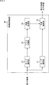
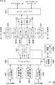
- FIG. 9 is a block diagram illustrating a first configuration example of the encoding device 11 of FIG.
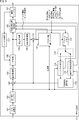
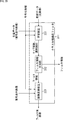
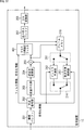
- the encoding device 11 includes an A / D conversion unit 101, a rearrangement buffer 102, a calculation unit 103, an orthogonal transformation unit 104, a quantization unit 105, a lossless encoding unit 106, and a storage buffer 107. Furthermore, the encoding device 11 includes an inverse quantization unit 108, an inverse orthogonal transform unit 109, a calculation unit 110, a class classification adaptive filter 111, a frame memory 112, a selection unit 113, an intra prediction unit 114, a motion prediction compensation unit 115, a prediction An image selection unit 116 and a rate control unit 117 are included.
- the A / D conversion unit 101 A / D converts the analog signal original image into a digital signal original image, and supplies the converted image to the rearrangement buffer 102 for storage.
- the rearrangement buffer 102 rearranges the frames of the original image in the order of encoding (decoding) from the display order according to GOP (Group Of Picture), the arithmetic unit 103, the intra prediction unit 114, the motion prediction compensation unit 115, and To the class classification adaptive filter 111.
- GOP Group Of Picture
- the calculation unit 103 subtracts the prediction image supplied from the intra prediction unit 114 or the motion prediction compensation unit 115 via the prediction image selection unit 116 from the original image from the rearrangement buffer 102 and obtains a residual obtained by the subtraction. (Prediction residual) is supplied to the orthogonal transform unit 104.
- the calculation unit 103 subtracts the predicted image supplied from the motion prediction / compensation unit 115 from the original image read from the rearrangement buffer 102.
- the orthogonal transform unit 104 performs orthogonal transform such as discrete cosine transform and Karhunen-Loeve transform on the residual supplied from the computation unit 103. Note that this orthogonal transformation method is arbitrary.
- the orthogonal transform unit 104 supplies transform coefficients obtained by the orthogonal exchange to the quantization unit 105.
- the quantization unit 105 quantizes the transform coefficient supplied from the orthogonal transform unit 104.
- the quantization unit 105 sets the quantization parameter QP based on the code amount target value (code amount target value) supplied from the rate control unit 117 and quantizes the transform coefficient. Note that this quantization method is arbitrary.
- the quantization unit 105 supplies the quantized transform coefficient to the lossless encoding unit 106.
- the lossless encoding unit 106 encodes the transform coefficient quantized by the quantization unit 105 using a predetermined lossless encoding method. Since the transform coefficient is quantized under the control of the rate control unit 117, the code amount of the encoded data obtained by the lossless encoding of the lossless encoding unit 106 is the code amount target set by the rate control unit 117. Value (or approximate the code amount target value).
- the lossless encoding unit 106 acquires necessary encoding information from the blocks among the encoding information related to predictive encoding in the encoding device 11.
- motion information such as a motion vector, code amount target value, quantization parameter QP, picture type (I, P, B), CU (Coding Unit) and CTU (Coding
- the prediction mode can be acquired from the intra prediction unit 114 or the motion prediction / compensation unit 115.
- the motion information can be acquired from the motion prediction / compensation unit 115.
- the lossless encoding unit 106 acquires encoding information, and also acquires filter information related to class classification adaptive processing in the class classification adaptive filter 111 from the class classification adaptive filter 111.
- the filter information includes a tap coefficient for each class as necessary.
- the lossless encoding unit 106 encodes the encoded information and the filter information by an arbitrary lossless encoding method, and uses it as part of the header information of the encoded data (multiplexes).
- the lossless encoding unit 106 transmits the encoded data via the accumulation buffer 107. Therefore, the lossless encoding unit 106 functions as a transmission unit that transmits encoded data, and thus encoded information and filter information included in the encoded data.
- variable length encoding or arithmetic encoding can be adopted.
- variable length coding include H.264.
- CAVLC Context-AdaptiveaptVariable Length Coding
- arithmetic coding include CABAC (Context-AdaptiveaptBinary Arithmetic Coding).
- the accumulation buffer 107 temporarily accumulates the encoded data supplied from the lossless encoding unit 106.
- the encoded data stored in the storage buffer 107 is read and transmitted at a predetermined timing.
- the transform coefficient quantized by the quantization unit 105 is supplied to the lossless encoding unit 106 and also to the inverse quantization unit 108.
- the inverse quantization unit 108 inversely quantizes the quantized transform coefficient by a method corresponding to the quantization by the quantization unit 105.
- the inverse quantization method may be any method as long as it is a method corresponding to the quantization processing by the quantization unit 105.
- the inverse quantization unit 108 supplies the transform coefficient obtained by the inverse quantization to the inverse orthogonal transform unit 109.
- the inverse orthogonal transform unit 109 performs inverse orthogonal transform on the transform coefficient supplied from the inverse quantization unit 108 by a method corresponding to the orthogonal transform process by the orthogonal transform unit 104.
- the inverse orthogonal transform method may be any method as long as it corresponds to the orthogonal transform processing by the orthogonal transform unit 104.
- the inversely orthogonally transformed output (restored residual) is supplied to the calculation unit 110.
- the calculation unit 110 is supplied from the intra prediction unit 114 or the motion prediction / compensation unit 115 to the inverse orthogonal transform result supplied from the inverse orthogonal transform unit 109, that is, the restored residual, via the predicted image selection unit 116.
- the prediction image is added, and the addition result is output as a decoding intermediate image.
- the decoding intermediate image output from the calculation unit 110 is supplied to the class classification adaptive filter 111 or the frame memory 112.
- the class classification adaptive filter 111 is a filter that functions as ILF, that is, all of DF, SAO, and ALF, by class classification adaptive processing, and performs ILF processing by class classification adaptive processing.
- the class classification adaptive filter 111 is supplied with the decoding-in-progress image from the calculation unit 110 and is supplied with the original image corresponding to the decoding-in-progress image from the rearrangement buffer 102 and is required from each block of the encoding device 11. Encoded information is supplied.
- the class classification adaptive filter 111 uses a student image corresponding to the intermediate decoding image from the calculation unit 110 and a teacher image corresponding to the original image from the rearrangement buffer 102, and uses encoded information as necessary. To learn the tap coefficient for each class.
- the class classification adaptive filter 111 uses, for example, the decoding intermediate image itself from the calculation unit 110 as a student image and the original image itself from the rearrangement buffer 102 as a teacher image, and encodes information as necessary. And learning to find the tap coefficient for each class.
- the tap coefficient for each class is supplied from the class classification adaptive filter 111 to the lossless encoding unit 106 as filter information.
- the class classification adaptive filter 111 performs the class classification adaptive processing (by image conversion) using the tap coefficient for each class, using the decoding intermediate image from the calculation unit 110 as the first image, and the encoded information as necessary. In this way, the halfway decoded image as the first image is converted into a filtered image as a second image corresponding to the original image (generates a filtered image) and output.
- the filtered image output from the class classification adaptive filter 111 is supplied to the frame memory 112.
- the class classification adaptive filter 111 learning is performed by using the mid-decoding image as the student image and the original image as the teacher image, and using the tap coefficient obtained by the learning, the mid-decoding is performed.
- a class classification adaptation process for converting an image into a filtered image is performed. Therefore, the filtered image obtained by the class classification adaptive filter 111 is an image very close to the original image.
- the frame memory 112 temporarily stores the decoding intermediate image supplied from the calculation unit 110 or the filtered image supplied from the class classification adaptive filter 111 as a locally decoded decoded image.
- the decoded image stored in the frame memory 112 is supplied to the selection unit 113 as a reference image used for generating a predicted image at a necessary timing.
- the selection unit 113 selects a supply destination of the reference image supplied from the frame memory 112. For example, when intra prediction is performed in the intra prediction unit 114, the selection unit 113 supplies the reference image supplied from the frame memory 112 to the intra prediction unit 114. For example, when inter prediction is performed in the motion prediction / compensation unit 115, the selection unit 113 supplies the reference image supplied from the frame memory 112 to the motion prediction / compensation unit 115.
- the intra prediction unit 114 basically uses the original image supplied from the rearrangement buffer 102 and the reference image supplied from the frame memory 112 via the selection unit 113 as a processing unit for PU (Prediction Unit). Intra prediction (in-screen prediction) is performed.
- the intra prediction unit 114 selects an optimal intra prediction mode based on a predetermined cost function (for example, RD (Rate-Distortion) cost), and selects a prediction image generated in the optimal intra prediction mode as a prediction image. It supplies to the selection part 116. Further, as described above, the intra prediction unit 114 appropriately supplies a prediction mode indicating the intra prediction mode selected based on the cost function to the lossless encoding unit 106 and the like.
- RD Red-Distortion
- the motion prediction / compensation unit 115 uses the original image supplied from the rearrangement buffer 102 and the reference image supplied from the frame memory 112 via the selection unit 113 to basically perform motion prediction using the PU as a processing unit. (Inter prediction) is performed. Furthermore, the motion prediction / compensation unit 115 performs motion compensation according to a motion vector detected by motion prediction, and generates a predicted image. The motion prediction / compensation unit 115 performs inter prediction in a plurality of inter prediction modes prepared in advance, and generates a prediction image.
- the motion prediction / compensation unit 115 selects an optimal inter prediction mode based on a predetermined cost function of the prediction image obtained for each of the plurality of inter prediction modes. Furthermore, the motion prediction / compensation unit 115 supplies the predicted image generated in the optimal inter prediction mode to the predicted image selection unit 116.
- the motion prediction / compensation unit 115 performs motion such as a prediction mode indicating an inter prediction mode selected based on a cost function and a motion vector necessary for decoding encoded data encoded in the inter prediction mode. Information or the like is supplied to the lossless encoding unit 106.
- the prediction image selection unit 116 selects a supply source (intra prediction unit 114 or motion prediction compensation unit 115) of a prediction image to be supplied to the calculation units 103 and 110, and selects a prediction image supplied from the selected supply source. , To the arithmetic units 103 and 110.
- the rate control unit 117 controls the quantization operation rate of the quantization unit 105 based on the code amount of the encoded data stored in the storage buffer 107 so that overflow or underflow does not occur. That is, the rate control unit 117 sets the target code amount of the encoded data so that the overflow and underflow of the accumulation buffer 107 do not occur, and supplies them to the quantization unit 105.
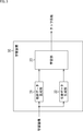
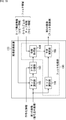
- FIG. 10 is a block diagram showing a configuration example of the class classification adaptive filter 111 of FIG.
- the class classification adaptive filter 111 includes a learning device 131, a filter information generation unit 132, and an image conversion device 133.
- the learning device 131 is supplied with the original image from the rearrangement buffer 102 (FIG. 9) and the decoding intermediate image from the calculation unit 110 (FIG. 9). Further, encoded information is supplied to the learning device 131.
- the learning device 131 performs learning for obtaining a tap coefficient for each class (hereinafter, also referred to as tap coefficient learning) using the decoding intermediate image as student data and the original image as teacher data.
- the learning device 131 uses the filter information generation unit 132 to generate tap coefficient information for each class obtained by tap coefficient learning and tap structure information representing the tap structure of the class tap used to obtain the tap coefficient for each class. To supply.
- the learning device 131 can perform class classification in the tap coefficient learning using encoded information as necessary.
- the filter information generation unit 132 generates filter information including tap coefficients and tap structure information for each class from the learning device 131 as necessary, and supplies the filter information to the image conversion device 133 and the lossless encoding unit 106 (FIG. 9). .
- the image conversion device 133 is supplied with filter information from the filter information generation unit 132, and is also supplied with decoding information from the calculation unit 110 (FIG. 9) and with encoded information.
- the image conversion apparatus 133 performs image conversion by class classification adaptive processing using the tap coefficient for each class included in the filter information from the filter information generation unit 132, with the decoding intermediate image as the first image.
- the decoding intermediate image as the first image is converted into a filtered image as a second image corresponding to the original image (a filtered image is generated) and supplied to the frame memory 112 (FIG. 9).
- the image conversion apparatus 133 can perform class classification using encoded information as necessary in the class classification adaptive processing.
- class classification is performed using the edge strength and direction difference of the class tap, but the tap structure of the class tap is fixed and is not updated (switched).
- the tap structure of the class tap When the tap structure of the class tap is fixed, it is possible to appropriately classify the decoding intermediate image according to the difference in spatial resolution and temporal resolution of the decoding intermediate image and other (local) characteristics of other decoding intermediate images. It can be difficult. In this case, even if the filtering process corresponding to the class of the decoding intermediate image is performed on the decoding intermediate image, it is difficult to obtain a sufficient image quality improvement effect for the filtered image obtained by the filtering process.
- the decoding intermediate image is appropriately classified according to the difference in the characteristics of the decoding intermediate image, and a filter suitable for the feature of the decoding intermediate image is used as the filter processing corresponding to the class of the decoding intermediate image.
- the tap structure of the class tap is adaptively updated (switched) for each predetermined picture sequence of the decoding intermediate image,
- the decoding-in-progress image is classified into a class suitable for the feature of the decoding-in-progress image.
- decoding is performed by performing filter processing using the tap coefficient for each class obtained by tap coefficient learning using the updated class taps of the tap structure on the intermediate decoding image.
- Appropriate filtering is applied to the characteristics of the halfway image, and the S / N of the filtered image obtained by the filtering is greatly improved.
- the characteristics in class classification are similar (the same).
- the decoding intermediate images to be included are classified into the same class, and the decoding intermediate images whose features are not similar are classified into different classes, so that the image quality improvement effect of the filtered image can be increased.
- Image features have various features.
- An image being decoded may not be classified into an appropriate class. That is, in class classification, a decoding-in-progress image may be classified into the same class as a class into which other decoding-in-progress images whose features are not very similar are classified.
- the image quality improvement effect of the filtered image obtained by the filter processing corresponding to the class is a plurality of decoding intermediate images whose features are similar. It is smaller than when images are classified into the same class.
- the image processing system of FIG. 1 by adaptively updating the tap structure of the class tap, in the class classification, it is possible to suppress a plurality of decoding-in-progress images whose features are not so similar from being classified into the same class.
- the image is classified into a class suitable for the feature of the image being decoded.
- the tap structure of the class tap is adaptively updated, so that the same number of classes as the class classification using the class tap of the fixed tap structure (classes that can be classified by the class classification).
- the S / N of the filtered image can be greatly improved even in the case of classifying the number of items. In this case, since the residual obtained using the filtered image as a reference image becomes small, the compression efficiency can be improved.
- the decoding intermediate image is matched with the characteristics of the decoding intermediate image. It is possible to classify into an appropriate class and greatly improve the S / N of the post-filter image obtained by the filtering process and suppress the deterioration of the compression efficiency.
- the tap structure of the class tap is adaptively updated, and the tap coefficient for each class obtained by the tap coefficient learning using the class tap of the updated tap structure is transmitted from the encoding device 11 to the decoding device 12.
- the frequency of transmission is high, the overhead increases and the compression efficiency deteriorates.
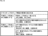
- class classification is performed by using the same tap structure as the previous tap structure update as the tap structure of the class tap.
- the S / N of the filtered image can be maintained even when the filtering process using the same tap coefficient for each class as in updating the tap structure is performed.
- the decoding apparatus 12 can continue to use the tap coefficient for each class used until immediately before. Therefore, it is not necessary to transmit tap coefficients or the like for each new class from the encoding device 11 to the decoding device 12, and the compression efficiency can be improved.
- the correlation in the time direction of the image being decoded is low, that is, for example, when the sequence of the image being decoded includes a scene of complex movement or a scene change, the scene has changed greatly due to a scene change or the like.
- class classification was performed using the same tap structure as when the previous tap structure was updated, and the same tap coefficient for each class as when the previous tap structure was updated was used.
- the filter process is performed, the image quality improvement effect of the filtered image is reduced, and the compression efficiency is deteriorated by the reduction.
- a decoding intermediate image having a low correlation in the time direction is detected (directly or indirectly), and the tap structure of the class tap is updated for the decoding intermediate image (hereinafter).
- a filter using a tap coefficient for each class obtained by detecting a decoding intermediate image having a low correlation in the time direction, updating the tap structure of the class tap, and learning the tap coefficient using the class tap of the tap structure When performing processing, the tap structure of the class tap is updated frequently for the sequence of the halfway image followed by a scene with low correlation in the time direction, and the tap using the class tap of the updated tap structure is used. Transmission of the tap coefficients for each class obtained by coefficient learning (from the encoding device 11 to the decoding device 12) may be frequently performed. When transmission of tap coefficients and the like for each class is frequently performed, compression efficiency deteriorates.
- a tap structure of a class tap that can expect an average image quality improvement effect (hereinafter also referred to as an average structure), and tap coefficient learning using the class tap of such a tap structure.
- an average tap coefficient can be prepared for each class obtained tap coefficient (hereinafter also referred to as an average tap coefficient).
- the learning device 131 has a tap structure of class taps, A plurality of tap structures are adopted, tap coefficient learning is performed for each of the plurality of tap structures, and a tap coefficient for each class is obtained.
- the learning device 131 obtains, for each of the plurality of tap structures, a tap structure evaluation value indicating the appropriateness of using the class tap of the tap structure for class classification, and the tap structure evaluation value is the best among the plurality of tap structures. Is selected as the optimum tap structure.
- the learning device 131 includes tap structure information representing the optimum tap structure and tap coefficients for each class of the optimum tap structure (tap coefficients for each class obtained by tap coefficient learning using class taps of the optimum tap structure). Is supplied to the filter information generation unit 132.
- the tap structure evaluation value of each of the plurality of tap structures for example, a filter process (for example, a class classification adaptive process) using a tap coefficient for each class of the tap structure is used as student data.
- a filter process for example, a class classification adaptive process
- the S / N or the like of the corresponding image corresponding to the original image as the teacher data obtained by performing the decoding intermediate result image can be employed.
- the tap structure evaluation value of each of the plurality of tap structures for example, when a filter process using a tap coefficient for each class of the tap structure is employed and the original image is encoded as teacher data RD cost etc. can be adopted.
- the filter information generation unit 132 generates filter information including the tap coefficient and the tap structure information for each class from the learning device 131 as necessary.
- the tap structure and tap of the previous tap are used as the tap structure for each class tap and the tap coefficient for each class. It is possible to include a flag or the like as copy information indicating whether to use the same tap structure and the tap coefficient for each class as when the coefficient is updated.
- the tap coefficient and tap structure information for each class is included by including copy information in the filter information without including the tap coefficient and tap structure information for each class, the data amount of the filter information Can be greatly reduced, and the compression efficiency can be improved.
- copy information indicating that the tap structure and the tap coefficient for each class that are the same as those used when updating the previous tap structure and tap coefficient are used as the tap structure for the class tap and the tap coefficient for each class. For example, when the latest tap structure information supplied from the learning device 131 matches the previous tap structure information supplied from the learning device 131, or the sequence of the original image used for this tap coefficient learning When the correlation in the time direction with the sequence of the original image used for the previous tap coefficient learning is high, it can be included in the filter information.
- a tap structure update unit for updating the tap structure (and tap coefficient) of a class tap for example, an arbitrary picture sequence such as a plurality of frames (pictures), one frame, CU or other blocks is adopted, and the tap is used.
- the tap structure of the class tap can be updated at the timing when the structure update unit is the minimum unit.
- the filter information is encoded data, for example, as Sequence parameter set syntax. Can be included.
- the filter information can be included in the encoded data as, for example, “Picture parameter” set “syntax”.
- the filter information can be included in the encoded data as, for example, Slice data syntax.
- the filter information can be included in any multiple layers of Sequence parameter set syntax, Picture parameter set syntax, and Slice data syntax.
- the filter information included in Slice data syntax can be preferentially applied to that block.
- the tap structure of the class tap can be represented by, for example, a positional relationship (including both a spatial positional relationship and a temporal positional relationship) of each pixel serving as the class tap with respect to the target pixel.
- the tap structure is different.
- Class taps having different positions of the class tap shape with respect to the pixel of interest include, for example, a class tap whose class tap shape is centered on the position of the pixel of interest, and a class tap centered on a position where the class tap shape is shifted from the pixel of interest. Means.
- the tap structures are different. This is because, when the class tap shapes are similar, the positional relationships of all pixels that are class taps with respect to the target pixel do not match.
- tap structure information representing the tap structure of the class tap position information with respect to the target pixel of each pixel that becomes the class tap of the tap structure can be adopted.
- the tap structure information When the position information of the pixel that becomes the class tap is adopted as the tap structure information, the data amount of the tap structure information becomes large, but the tap structure of the class tap can be controlled flexibly.
- the tap structure information for example, a unique ID (Identification) assigned to each of a plurality of tap structures can be adopted.
- a plurality of tap structures are determined in advance, an ID is assigned to each of the plurality of tap structures, and each tap structure and an ID assigned to the tap structure are used as prior knowledge as an encoding device. 11 and the decoding device 12 are assumed to be shared.
- the unique ID assigned to the tap structure is adopted as the tap structure information, the flexibility of the tap structure of the class tap is reduced, but the data amount of the tap structure information can be reduced.
- a unique ID (hereinafter also referred to as a shape ID) assigned to each of a plurality of class tap shapes, the number of pixels to be a class tap, a center of the class tap shape, and the like are predetermined. It is possible to adopt a set of position information of the point with respect to the target pixel.
- a plurality of class tap shapes are determined in advance, a shape ID is assigned to each of the plurality of class tap shapes, and each class tap shape and the shape ID assigned to the class tap shape are assigned in advance. It is assumed that knowledge is shared between the encoding device 11 and the decoding device 12.
- the flexibility of the tap structure of the class tap is to some extent As well as ensuring, the data amount of the tap structure information can be reduced to some extent.
- FIG. 11 is a block diagram illustrating a configuration example of the learning device 131 in FIG.
- the learning device 131 includes a tap structure selection unit 151, a learning unit 152, a storage unit 153, an evaluation value calculation unit 154, and a selection unit 155.
- the tap structure selection unit 151 stores, for example, a plurality of predetermined tap structure candidates (information thereof), and sequentially selects the plurality of tap structure candidates as the target tap structure. Then, the tap structure selection unit 151 supplies tap structure information representing the target tap structure to the learning unit 152 (the tap selection unit 162) and the storage unit 153.
- the learning unit 152 includes tap selection units 161 and 162, a class classification unit 163, an addition unit 164, and a coefficient calculation unit 165.
- the tap selection unit 161 through the coefficient calculation unit 165 perform the same processing as the tap selection unit 41 through the coefficient calculation unit 45 that constitute the learning unit 33 in FIG.
- the learning unit 152 is supplied with a decoding intermediate image as student data, an original image as teacher data, and encoding information. Then, the learning unit 152 uses the decoding intermediate image as the student data and the original image as the teacher data, and uses the encoded information as necessary, and performs the tap coefficient learning similar to the learning unit 33 in FIG. And tap coefficients for each class are obtained.
- tap structure information is supplied from the tap structure selection unit 151 to the tap selection unit 162.
- the tap selection unit 162 selects a pixel to be a class tap from the pixels in the decoding-in-progress image for the target pixel, and configures a class tap with the pixel.
- the tap structure information from the tap structure selection unit 151 the class tap of the tap structure represented by the tap structure information is configured.
- the class classification unit 163 performs class classification of the target pixel using the class tap configured by the tap selection unit 162.
- class classification unit 163 can classify the pixel of interest using the class tap of the pixel of interest and the encoding information of the pixel of interest.
- the target pixel encoding information used for class classification includes, for example, the block phase indicating the position of the target pixel in a block such as a CU or PU including the target pixel, the picture type of the picture including the target pixel, and the target pixel.
- a PU quantization parameter QP or the like can be employed.
- the pixel of interest When adopting the block phase as the encoding information of the pixel of interest used for class classification, the pixel of interest can be classified according to, for example, whether the pixel of interest is a pixel at the boundary of the block.
- the picture type is adopted as the encoding information of the target pixel used for class classification, for example, depending on whether the picture including the target pixel is an I picture, a P picture, or a B picture The pixel of interest can be classified.
- the quantization parameter QP when adopted as the encoding information of the pixel of interest used for class classification, the pixel of interest can be classified according to the roughness (fineness) of the quantization, for example.
- the target pixel is classified into the first subclass using the class tap, and the second subclass is classified using the encoding information. Then, the (final) class of the pixel of interest can be obtained from the first subclass and the second subclass. For example, a value obtained by arranging a bit string representing the first subclass and a bit string representing the second subclass in one bit string can be obtained as the class of the pixel of interest (representing a class code).
- the learning unit 152 performs tap coefficient learning for each of the plurality of tap structures (candidates) stored in the tap structure selection unit 151, and obtains a tap coefficient for each class.
- the tap coefficient for each class obtained by the learning unit 152 performing tap coefficient learning for each of the plurality of tap structures is supplied to the storage unit 153.
- the storage unit 153 stores the tap structure information representing the target tap structure supplied from the tap structure selection unit 151 and the tap coefficient for each class of the target tap structure supplied from the learning unit 152 in association with each other.
- the evaluation value calculation unit 154 obtains and selects a tap structure evaluation value representing the appropriateness of using the class tap of the tap structure for class classification for each of the plurality of tap structures (candidates) stored in the tap structure selection unit 151. Part 155.
- the evaluation value calculation unit 154 is supplied with a decoding intermediate image as student data, an original image as teacher data, and encoding information similar to those supplied to the learning unit 152.
- the evaluation value calculation unit 154 includes an image conversion unit 171 and a calculation unit 172.
- the image conversion unit 171 performs the class classification adaptive process by using the decoding-in-progress image supplied to the evaluation value calculation unit 154 as the first image, thereby setting the decoding-in-progress image as the first image as the second image. Is converted into an equivalent image corresponding to the original image and supplied to the calculation unit 172.
- the image conversion unit 171 includes, for each of the plurality of tap structure information stored in the storage unit 153 (the tap structure information for each of the plurality of tap structures stored in the tap structure selection unit 151), Then, the class classification adaptive process is performed using the tap coefficient for each class associated with the tap structure information.
- the image conversion unit 171 configures a tap having a tap structure represented by the tap structure information, and is associated with the tap structure information.
- a class classification adaptive process is performed in which a filter process using a tap coefficient for each class (in this case, for example, a prediction calculation of Expression (1)) is performed.
- the image conversion unit 171 supplies an equivalent image obtained for each of the plurality of tap structure information to the calculation unit 172.
- the calculation unit 172 uses the equivalent image obtained for each of the plurality of tap structure information from the image conversion unit 171 and the original image as teacher data, for example, to calculate a value corresponding to the S / N of the equivalent image.
- the tap structure evaluation value is obtained and supplied to the selection unit 155.
- the selection unit 155 selects the tap structure information having the best tap structure evaluation value supplied from the evaluation value calculation unit 154 (the calculation unit 172) from the tap structure information stored in the storage unit 153, and selects the optimum tap structure. Select as tap structure information to represent. Further, the selection unit 155 selects the tap coefficient for each class associated with the tap structure information representing the optimal tap structure from the tap coefficients for each class stored in the storage unit 153 (hereinafter, the class for the optimal tap structure). Each tap coefficient).
- the selection unit 155 supplies the tap structure information representing the optimum tap structure and the tap coefficient for each class regarding the optimum tap structure to the filter information generation unit 132 (FIG. 10).
- the processing for obtaining tap structure information representing the optimum tap structure and the tap coefficient for each class for the optimum tap structure is the same unit as the tap structure update unit described in FIG. Timing).
- FIG. 12 is a diagram illustrating an example of a class tap shape as a tap structure of a class tap.
- the class tap shape formed by the pixel to be the class tap for example, as shown in FIG. 12, a cross type, an X type, a horizontal one line type, a vertical one line type, an oblique one line type, a rhombus, a square, or a vertically long shape There are rectangles and horizontally long rectangles.
- the simulation it is obtained by tap coefficient learning using a class tap having an X-type tap structure in which pixels arranged in one line in the upper right direction and pixels arranged in one line in the upper left direction cross.
- the PSNR Peak signal-to-noise ratio
- the PSNR of the second image obtained by the class classification adaptive process is improved by changing the tap structure of the class tap according to the feature of the image (here, the direction of the edge).
- the class tap shape in FIG. 12 is formed by pixels of one frame, but the class tap can be formed of pixels of one frame or a plurality of frames.
- FIG. 13 is a diagram illustrating an example of a tap structure of a class tap composed of pixels of a plurality of frames.
- the class tap is configured by using not only the pixels in the spatial direction of the target pixel but also the pixels in the time direction of the target pixel. That is, in FIG. 13, in addition to the pixel of the target pixel frame t, the class tap is configured using the pixel of frame t ⁇ 1 one frame before frame t and the pixel of frame t + 1 one frame after. Has been.
- the pixel at the same position as the position of the target pixel and the pixels around the pixel can be selected as the pixels to be the class tap.
- a pixel that is moved by a motion vector from the position of the pixel of interest and that shows the same subject as the pixel of interest and pixels around the pixel are class taps. It can be selected as a pixel.
- the second image obtained by the class classification adaptive processing is used.
- the target pixel is classified according to the image feature amount (local image feature amount) of the target pixel obtained from the pixels constituting the class tap.
- the ADRC code described in FIG. 2 or the like, DiffMax described later, or the like can be used.
- an ADRC code is used as an image feature amount used for class classification, it is desirable to adopt a tap structure with a small number of pixels as the tap structure of the class tap from the viewpoint of compression efficiency.
- a class tap CT1 configured by selecting pixels forming a cross-type class tap shape from each of the frames t-1 to t + 1 and a square from each of the frames t-1 to t + 1.
- a class tap CT2 configured by selecting pixels forming the class tap shape is shown.
- the class tap CT1 is composed of 19 pixels, and the class tap CT2 is composed of 75 pixels.
- the class tap CT1 having a tap structure with a small number of pixels. Even if the class tap CT2 having a tap structure with a large number of pixels is employed, the compression efficiency does not change due to the change in the number of classes.
- the image feature amount of the target pixel is often accurately obtained when the number of pixels constituting the class tap is large. Therefore, when an image feature quantity that does not affect the number of classes, such as DiffMax, is used as an image feature quantity used for class classification, the class tap CT2 having a tap structure with a large number of pixels. By adopting, the image feature amount of the target pixel can be accurately obtained.
- the class tap shape of the class tap configured using the pixels in the time direction of the target pixel is also referred to as a time direction type hereinafter.
- FIG. 14 is a diagram showing an example of a variation of the tap structure of the class tap.
- class tap shape For example, as shown in FIG. 14, there are class taps in which the pixels constituting the class tap are dense and class taps in which the pixels constituting the class tap are sparse. .
- Class taps with dense pixels are, for example, class taps in which adjacent pixels are the pixels constituting the class tap, and class taps with sparse pixels are, for example, every other one. Or a class tap in which every other pixel is a pixel constituting the class tap.
- the class tap is composed of pixels located in the spatial direction of the pixel of interest, and pixels located in the time direction are not considered.
- FIG. 15 is a diagram for explaining an example of a method of determining a plurality of class tap (candidates) of class taps to be stored in the tap structure selection unit 151 (FIG. 11).
- a method for determining a plurality of tap structures of class taps for example, there are a method of setting the class tap shape in the same range as the predicted tap shape and a method of not setting the class tap shape in the same range as the predicted tap shape.
- the prediction tap shape means a shape formed by the pixels constituting the prediction tap.
- the class tap shape is matched with the predicted tap shape (the class tap shape is the same shape as the predicted tap shape), and the class tap shape.
- the maximum range in the horizontal direction and the vertical direction of the horizontal direction and the maximum range in the vertical direction of the predicted tap shape is matched with the predicted tap shape.
- the maximum horizontal range and vertical range of the class tap shape are matched to the maximum horizontal range and vertical range of the predicted tap shape, respectively.
- the smallest rectangle that surrounds the class tap shape is the smallest that surrounds the predicted tap shape. Means match the rectangle.
- the pixels constituting the class tap are the smallest rectangles surrounding the predicted tap shape. Distributed within.
- the class tap shape does not necessarily match the predicted tap shape.
- the method of matching the maximum range in only one of the horizontal direction and the vertical direction there is a method in which the maximum range in either the horizontal direction or the vertical direction is not matched between the tap shape and the predicted tap shape.
- the horizontal direction of the pixels constituting the class tap and the pixels constituting the prediction tap match, but the class tap shape does not match the predicted tap shape.
- the range in which the pixels constituting the class tap are distributed and the range in which the pixels constituting the predicted tap are distributed may overlap.
- FIG. 16 is a diagram illustrating an example of class tap image feature values used by the class classification unit 163 of FIG. 11 for class classification.
- an image feature quantity of a class tap used for class classification for example, an ADRC code, DR, DiffMax, stationarity, activity, secondary differential sum, maximum direction difference, filter bank output, and the like can be adopted.
- the ADRC code can be obtained as described in FIG. That is, for example, a 1-bit ADRC code can be obtained by dividing a pixel value such as the luminance of a pixel constituting a class tap into two values by a threshold value and arranging the binary pixel values.
- waveform patterns edges and textures (including directions)
- class taps groups of pixels
- DR is the difference between the maximum and minimum pixel values such as the brightness of the pixels that make up the class tap.
- Class classification using DR contributes to reduction of noise or the like in a flat part when DR is small in the class classification adaptation process, and contributes to edge restoration when DR is large.
- DiffMax is the maximum difference absolute value of pixel values of pixels adjacent in the horizontal, vertical and diagonal directions in the class tap. Class classification using DiffMax contributes to a reduction in gradation false contours when DiffMax is small in the classification adaptation process, and sharp edges (steps) are restored when DiffMax is large. Contribute to.
- DiffMax DR
- DR DR
- DiffMax DR
- DR biaxial representation of DiffMax and DR
- the continuity can be represented by a value representing a difference in the sum of absolute differences between the maximum direction and the minimum direction of the difference absolute value sum of the pixel values of adjacent pixels in each direction in the class tap.
- Class classification using stationarity contributes to the restoration of textures (and fine patterns such as noise) when the stationarity is small in the classification adaptation process, and when stationarity is large. This contributes to the restoration of edges (structural lines).
- the activity can be represented by, for example, a sum of absolute differences of pixel values of pixels adjacent in the horizontal and vertical directions in the class tap.
- Class classification using activities contributes to the restoration of step edges (simple patterns) when the activity is small in the classification adaptation process, and textures (complex patterns) when the activity is large. ).
- the secondary differential sum is, for example, the absolute value sum of the secondary differential of the pixel values of pixels adjacent in the horizontal and vertical directions in the class tap.
- the classification using the second derivative sum contributes to the restoration of the step edge when the second derivative sum is small, and contributes to the restoration of the texture when the second derivative sum is large.
- the maximum direction difference is, for example, a value representing a direction in which the sum of absolute differences of pixel values of pixels adjacent in the horizontal, vertical, and diagonal directions is maximized in the class tap.
- the class classification using the maximum direction difference classifies the direction of the amplitude, gradient, structure, etc. around the pixel of interest, so that in the class classification adaptive processing, the amplitude around the pixel of interest, gradient, structure, etc. An optimal image restoration effect can be obtained for each direction.
- the filter bank output is the pixel value of the pixels constituting the class tap for a plurality of directional bandpass filters (bandpass filters that output values indicating the direction of the image amplitude, gradient, structure, etc.). This is the value obtained by input.
- the classification using the filter bank output has a high calculation cost, but the classification accuracy is higher than the classification using the maximum direction difference.
- the ADRC code value represented
- the class of the pixel of interest can be adopted as the class code.
- Image features of class taps used for class classification include ADRC code, DR, DiffMax, stationarity, activity, secondary differential sum, maximum direction difference, filter bank output, and other image features as described above. The quantity can be adopted.
- Class classification using image features such as DR of class taps, DiffMax (DiffMax / DR), stationarity, activity, second-order differential sum, maximum direction difference, filter bank output, etc.
- the image feature quantity can be compared with one or more threshold values, and a value representing the magnitude relationship between the image feature quantity and the threshold value can be adopted as the class of the pixel of interest.
- the classification can be performed by using one type of image feature amount of the class tap or by using a plurality of types of image feature amounts of the class tap.
- FIG. 17 is a block diagram illustrating a configuration example of the image conversion unit 171 in FIG.
- the image conversion unit 171 includes tap selection units 181 and 182, a class classification unit 183, a coefficient acquisition unit 184, and a prediction calculation unit 185.
- the tap selection unit 181 to the prediction calculation unit 185 perform the same processing as the tap selection unit 21 to the prediction calculation unit 25 of the image conversion apparatus 20 in FIG.
- the image conversion unit 171 is supplied with a decoding intermediate image and encoded information as student data similar to that supplied to the learning unit 152 (FIG. 11).
- the image conversion unit 171 performs the class classification adaptation process similar to that of the image conversion apparatus 20 in FIG. 2 using the decoding intermediate image as the student data and using the encoded information as necessary, and as the teacher data. An equivalent image corresponding to the original image is obtained.
- the tap selection unit 182 and the coefficient acquisition unit 184 include tap structure information stored in the storage unit 153 (FIG. 11) and taps for each class associated with the tap structure information. Each coefficient is supplied.
- the tap selection unit 182 selects a pixel to be a class tap from the pixels in the image being decoded for the target pixel, and configures a class tap by the pixel.
- a class tap having a tap structure represented by the tap structure information is configured.
- the class classification unit 183 classifies the target pixel using the class tap configured by the tap selection unit 182.
- the class classification unit 183 performs the same class classification as the class classification unit 163 in FIG. Therefore, when the class classification unit 163 in FIG. 11 performs the class classification of the pixel of interest using the class tap of the pixel of interest and the encoding information of the pixel of interest, the class classification unit 183 also uses the class tap of the pixel of interest. And classifying the pixel of interest using the encoding information.
- the coefficient acquisition unit 184 stores the tap coefficient for each class, and acquires the tap coefficient of the class of the target pixel from the class classification unit 183 from the tap coefficient for each class. To the prediction calculation unit 185.
- the coefficient acquisition unit 184 stores the tap coefficient for each class from the storage unit 153 (FIG. 11), and acquires the tap coefficient for the class of the target pixel from the tap coefficient for each class.
- the tap coefficient for each class stored in the coefficient acquisition unit 184 is a tap coefficient for each class associated with the tap structure information supplied from the storage unit 153 to the tap selection unit 182, and the tap structure information represents the tap coefficient.
- This is a tap coefficient for a class obtained by classification using a class tap of the structure.
- the prediction calculation unit 185 uses the prediction tap of the target pixel configured by the tap selection unit 181 and the tap coefficient of the target pixel class acquired by the coefficient acquisition unit 184. Thus, a prediction calculation is performed to obtain a predicted value of the pixel value of the corresponding pixel corresponding to the original image corresponding to the target pixel.
- the prediction calculation performed by the prediction calculation unit 185 can be said to be a kind of filter processing for the prediction tap of the target pixel. Therefore, the tap selection unit 181 constituting the prediction tap to be subjected to the filter processing is used for the filter processing. It can be said that the coefficient acquisition unit 184 that acquires the tap coefficient and the prediction calculation unit 185 that performs the prediction calculation as a kind of filter processing constitute a filter processing unit 180 that performs the filter processing.
- the prediction calculation as the filter processing by the prediction calculation unit 185 is different filter processing depending on the tap coefficient of the class of the pixel of interest acquired by the coefficient acquisition unit 184. Therefore, it can be said that the filter processing of the filter processing unit 180 is filter processing corresponding to the class of the target pixel.
- FIG. 18 is a flowchart illustrating an example of processing of the learning device 131 in FIG.
- step S11 the tap structure selection unit 151 selects, as a target tap structure, one of the tap structure candidates that has not yet been selected as the target tap structure from among a plurality of predetermined tap structure candidates. Then, the tap structure selection unit 151 supplies (outputs) tap structure information representing the target tap structure to the tap selection unit 162 and the storage unit 153 of the learning unit 152, and the process proceeds from step S11 to step S12. .
- step S12 the learning unit 152 uses the decoding intermediate image as the student data and the original image as the teacher data, performs tap coefficient learning using the encoded information as necessary, and taps for each class. Find the coefficient.
- class classification is performed using the class tap of the target tap structure represented by the tap structure information supplied from the tap structure selection unit 151 to the tap selection unit 162, and such class classification is performed.
- the tap coefficient for the class obtained by the above is obtained.
- the learning unit 152 supplies the tap coefficient for each class obtained by class classification using the class tap of the target tap structure to the storage unit 153, and the process proceeds from step S12 to step S13.
- step S ⁇ b> 13 the storage unit 153 taps for each class obtained by the class classification using the tap structure information representing the tap structure of interest from the tap structure selection unit 151 and the class tap of the tap structure of interest from the learning unit 152.
- the coefficients are stored in association with each other, and the process proceeds to step S14.
- step S14 the tap structure selection unit 151 determines whether there is a tap structure candidate that has not yet been selected as the target tap structure among a plurality of predetermined tap structure candidates.
- step S14 when it is determined that there is a tap structure candidate that has not yet been selected as the target tap structure among a plurality of predetermined tap structure candidates, the process returns to step S11, and the same processing is performed hereinafter. Is repeated.
- step S14 If it is determined in step S14 that there is no tap structure candidate that is not the target tap structure among a plurality of predetermined tap structure candidates, that is, a plurality of predetermined tap structure candidates (candidates). )
- a plurality of predetermined tap structure candidates candidates.
- step S ⁇ b> 15 in the evaluation value calculation unit 154, the image conversion unit 171 has a plurality of tap structure information stored in the storage unit 153 (tap structure information for each of the plurality of tap structures stored in the tap structure selection unit 151. ) For each, using the tap structure information and the tap coefficient for each class associated with the tap structure information, performing class classification adaptive processing on the decoding intermediate image as student data, the teacher data An equivalent image corresponding to the original image is obtained.
- the evaluation value calculation unit 154 for each of the plurality of tap structure information, the equivalent image obtained by the class classification adaptive process using the tap coefficient for each class associated with the tap structure information. A value or the like corresponding to the S / N is obtained as a tap structure evaluation value and supplied to the selection unit 155.
- step S15 the process proceeds from step S15 to step S16, and the selection unit 155 selects the tap structure evaluation value supplied from the calculation unit 172 of the evaluation value calculation unit 154 from the tap structure information stored in the storage unit 153.
- the best tap structure information is selected as tap structure information representing the optimum tap structure.
- the selection unit 155 selects the tap coefficient for each class regarding the optimum tap structure from the tap coefficients for each class stored in the storage unit 153 (for each class associated with the tap structure information indicating the optimum tap structure). Select the tap coefficient.
- the selection unit 155 supplies the tap structure information representing the optimal tap structure and the tap coefficient for each class regarding the optimal tap structure to the filter information generation unit 132, and the process ends.
- FIG. 19 is a block diagram illustrating a configuration example of the image conversion device 133 in FIG.
- the image conversion apparatus 133 includes tap selection units 191 and 192, a class classification unit 193, a coefficient acquisition unit 194, and a prediction calculation unit 195.
- the tap selection unit 191 to the prediction calculation unit 195 perform the same processing as the tap selection unit 181 to the prediction calculation unit 185 of the image conversion unit 171 in FIG.
- the image conversion device 133 is supplied with a decoding intermediate image as the first image and encoding information.
- the image conversion apparatus 133 while using the decoding intermediate image as the first image and using the encoded information as necessary, the same class classification adaptation processing as that of the image conversion unit 171 in FIG. A filtered image as a second image corresponding to is obtained.
- filter information is supplied from the filter information generation unit 132 (FIG. 10) to the tap selection unit 192 and the coefficient acquisition unit 194.
- the tap selection unit 192 selects a pixel to be a class tap from the pixels in the decoding intermediate image with respect to the pixel of interest, thereby configuring a class tap with the pixel.
- the tap selection unit 192 configures the class tap of the optimum tap structure represented by the tap structure information in accordance with the tap structure information included in the filter information from the filter information generation unit 132.
- the class classification unit 193 uses the class tap configured by the tap selection unit 192 to perform the same class classification as the class classification unit 183 in FIG.
- the class classification unit 193 when the class classification unit 183 in FIG. 17 performs the class classification of the target pixel using the class tap of the target pixel and the encoding information, the class classification unit 193 also determines the class classification of the target pixel. This is performed using class taps and encoding information.
- the coefficient acquisition unit 194 stores the tap coefficient for each class, and acquires the tap coefficient of the class of the pixel of interest from the class classification unit 193 from the tap coefficient for each class. To the prediction calculation unit 195.
- the coefficient acquisition unit 194 stores the tap coefficient for each class included in the filter information from the filter information generation unit 132 (FIG. 10), and acquires the tap coefficient of the class of the target pixel from the tap coefficient for each class. To do.
- the tap coefficient for each class included in the filter information from the filter information generation unit 132 is a tap coefficient for each class obtained by class classification using the class tap of the optimum tap structure, which is obtained by the learning device 131 (FIG. 11). is there.
- the tap selection unit 191, the coefficient acquisition unit 194, and the prediction calculation unit 195 are the same as the tap selection unit 181, the coefficient acquisition unit 184, and the prediction calculation unit 185 in FIG. 17.
- the filter processing unit 190 that performs the filter processing corresponding to the class of the target pixel is configured.
- the filter information supplied from the filter information generation unit 132 to the image conversion device 133 includes the tap structure of the class tap and the tap coefficient for each class, as described in FIG. Copy information indicating whether or not to use the same tap structure and the tap coefficient for each class as in the update can be included.
- the tap selection unit 192 supplies the image conversion device 133 from the filter information generation unit 132.
- the tap structure represented by the tap structure information included in the latest filter information is employed as the tap structure of the class tap.
- the coefficient acquisition unit 194 stores the tap coefficient for each class included in the latest filter information in a form of overwriting the tap coefficient for each class included in the previous filter information.
- the tap selection unit 192 displays the previous filter information.
- the included tap structure is adopted as the tap structure of the class tap as it is.
- the coefficient acquisition unit 194 maintains the storage of the tap coefficient for each class included in the previous filter information as it is.
- the tap structure of the immediately preceding class tap and the tap coefficient for each class are maintained.
- FIG. 20 is a flowchart for explaining an example of the encoding process of the encoding device 11 of FIG.
- the learning device 131 (FIG. 10) of the class classification adaptive filter 111 includes, for example, a plurality of frames, one frame, a block, and other tap structure update units among the decoding intermediate images supplied thereto. Tap coefficient learning is performed from time to time using the halfway image as student data and the original image corresponding to the middle image as teacher data.
- the learning device 131 determines whether it is the update timing of the tap structure of the class tap (predetermined timing for updating the tap structure of the class tap), that is, for example, a plurality of frames, one frame, a block, and the like. It is determined whether it is the timing of the end point or start point of the tap structure update unit.
- step S31 If it is determined in step S31 that it is not the update timing of the tap structure of the class tap, the process skips steps S32 to S34 and proceeds to step S35.
- step S31 If it is determined in step S31 that it is the update timing of the tap structure of the class tap, the process proceeds to step S32.
- step S32 the filter information generation unit 132 (FIG. 10) generates tap structure information generated by the learning device 131 through the latest tap coefficient learning and tap coefficients (or copy information) for each class, that is, taps representing the optimal tap structure.
- the filter information including the tap information for each class about the structure information and the optimum tap structure is generated and supplied to the image conversion device 133 (FIG. 10) and the lossless encoding unit 106 (FIG. 9). Proceed to S33.
- the encoding device 11 detects the correlation in the time direction of the original image, and generates filter information at the update timing only when the correlation is low (when it is equal to or less than the threshold), in steps S33 and S34 described later. Processing can be performed.
- step S33 the image conversion apparatus 133 sends the tap structure of the class tap configured by the tap selection unit 192 (FIG. 19) and the coefficient acquisition unit 194 (FIG. 19) according to the filter information from the filter information generation unit 132.
- the stored tap coefficient for each class is updated, and the process proceeds to step S34.
- step S34 the lossless encoding unit 106 sets the filter information supplied from the filter information generating unit 132 as a transmission target, and the process proceeds to step S35.
- the filter information set as the transmission target is included in the encoded data and transmitted in step S48 described later.
- step S35 the predictive encoding process of the original image is performed.
- step S35 the A / D conversion unit 101 performs A / D conversion on the original image, supplies the original image to the rearrangement buffer 102, and the process proceeds to step S36.
- step S36 the rearrangement buffer 102 stores the original images from the A / D conversion unit 101, rearranges them in the encoding order, and outputs them, and the process proceeds to step S37.
- step S37 the intra prediction unit 114 performs an intra prediction process in the intra prediction mode, and the process proceeds to step S38.
- step S38 the motion prediction / compensation unit 115 performs an inter motion prediction process for performing motion prediction and motion compensation in the inter prediction mode, and the process proceeds to step S39.
- a cost function of various prediction modes is calculated and a prediction image is generated.
- step S39 the predicted image selection unit 116 determines an optimal prediction mode based on each cost function obtained by the intra prediction unit 114 and the motion prediction compensation unit 115. Then, the predicted image selection unit 116 selects and outputs the predicted image of the optimal prediction mode among the predicted image generated by the intra prediction unit 114 and the predicted image generated by the motion prediction / compensation unit 115, and performs processing. Advances from step S39 to step S40.
- step S ⁇ b> 40 the calculation unit 103 calculates a residual between the encoding target image that is the original image output from the rearrangement buffer 102 and the predicted image output from the predicted image selection unit 116, and the orthogonal transform unit 104. The process proceeds to step S41.
- step S41 the orthogonal transform unit 104 orthogonally transforms the residual from the calculation unit 103, supplies the transform coefficient obtained as a result to the quantization unit 105, and the process proceeds to step S42.
- step S42 the quantization unit 105 quantizes the transform coefficient from the orthogonal transform unit 104, and supplies the quantized coefficient obtained by the quantization to the lossless encoding unit 106 and the inverse quantization unit 108 for processing. Advances to step S43.
- step S43 the inverse quantization unit 108 inversely quantizes the quantization coefficient from the quantization unit 105, supplies the transform coefficient obtained as a result to the inverse orthogonal transform unit 109, and the process proceeds to step S44.
- step S44 the inverse orthogonal transform unit 109 performs inverse orthogonal transform on the transform coefficient from the inverse quantization unit 108, supplies the residual obtained as a result to the arithmetic unit 110, and the process proceeds to step S45.
- step S ⁇ b> 45 the calculation unit 110 adds the residual from the inverse orthogonal transform unit 109 and the predicted image output from the predicted image selection unit 116, and is the source of the residual calculation target in the calculation unit 103.
- a decoding intermediate image corresponding to the image is generated.
- the computing unit 110 supplies the decoding-in-progress image to the class classification adaptive filter 111 or the frame memory 112, and the process proceeds from step S45 to step S46.
- the class classification adaptive filter 111 applies the class classification adaptive processing as the ILF processing to the decoding intermediate image from the arithmetic unit 110. (Class classification adaptive filter processing) is performed.
- Class classification adaptive filter processing By applying the classification adaptation process to the decoding-in-progress image, a filtered image closer to the original image is obtained than when the decoding-in-progress image is filtered by a general ILF.
- the class classification adaptive filter 111 supplies the filtered image obtained by the class classification adaptation process to the frame memory 112, and the process proceeds from step S46 to step S47.
- step S47 the frame memory 112 stores the decoded image supplied from the calculation unit 110 or the filtered image supplied from the class classification adaptive filter 111 as a decoded image, and the process proceeds to step S48.
- the decoded image stored in the frame memory 112 is used as a reference image from which a predicted image is generated in steps S38 and S39.
- step S48 the lossless encoding unit 106 encodes the quantization coefficient from the quantization unit 105. Further, the lossless encoding unit 106 uses the quantization parameter QP used for quantization in the quantization unit 105, the prediction mode obtained by the intra prediction process in the intra prediction unit 114, and the motion prediction compensation unit 115. Encoding information such as a prediction mode and motion information obtained by the inter motion prediction process is encoded as necessary and included in the encoded data.
- the lossless encoding unit 106 encodes the filter information set as the transmission target in step S34 and includes the encoded information in the encoded data. Then, the lossless encoding unit 106 supplies the encoded data to the accumulation buffer 107, and the process proceeds from step S48 to step S49.
- step S49 the accumulation buffer 107 accumulates the encoded data from the lossless encoding unit 106, and the process proceeds to step S50.
- the encoded data stored in the storage buffer 107 is appropriately read and transmitted.
- step S50 the rate control unit 117 performs quantization of the quantization unit 105 based on the code amount (generated code amount) of the encoded data stored in the storage buffer 107 so that overflow or underflow does not occur.
- the rate of operation is controlled and the encoding process ends.
- FIG. 21 is a flowchart for explaining an example of the class classification adaptation process performed in step S46 of FIG.
- step S61 the tap selection unit 191 is still interested in the pixels of the decoding intermediate image (as a block) supplied from the calculation unit 110.
- One of the pixels not selected as a pixel is selected as a target pixel, and the process proceeds to step S62.
- step S62 the tap selection unit 191 selects a pixel to be a prediction tap for the target pixel from the decoding intermediate image supplied from the calculation unit 110, and configures a prediction tap. And the tap selection part 191 supplies a prediction tap to the prediction calculating part 195, and a process progresses to step S63.
- step S63 the tap selection unit 192 determines the class tap for the pixel of interest from the decoding intermediate image supplied from the calculation unit 110 according to the tap structure information included in the filter information from the filter information generation unit 132 (FIG. 10). The pixel to be selected is selected, and thereby the class tap of the optimum tap structure represented by the tap structure information included in the filter information is configured. Then, the tap selection unit 192 supplies the class tap to the class classification unit 193.
- the tap structure of the class tap configured by the tap selection unit 192 is updated by the update of the tap structure of the class tap performed in step S33 of FIG. 20 performed immediately before, and the tap selection unit 192 displays the updated tap.
- the structure class tap is configured and supplied to the class classification unit 193.
- step S63 the process proceeds from step S63 to step S64, and the class classification unit 193 uses the class tap for the target pixel and uses the encoding information about the target pixel as necessary to classify the target pixel. Do. Then, the class classification unit 193 supplies the class of the target pixel obtained by the class classification to the coefficient acquisition unit 194, and the process proceeds from step S64 to step S65.
- the coefficient acquisition unit 194 obtains the tap coefficient for each class included in the filter information supplied from the filter information generation unit 132, that is, the tap coefficient for each class for the optimum tap structure of the class tap configured by the tap selection unit 192. This is stored by updating the tap coefficient in step S33 of FIG. 20 performed immediately before.
- step S ⁇ b> 65 the coefficient acquisition unit 914 acquires the tap coefficient of the class of the pixel of interest supplied from the class classification unit 193 from the tap coefficient for each class regarding the stored optimal tap structure, and sends it to the prediction calculation unit 195. Then, the process proceeds to step S66.
- step S66 the prediction calculation unit 195 performs the prediction calculation of Expression (1) as a filter process using the prediction tap from the tap selection unit 191 and the tap coefficient from the coefficient acquisition unit 194. Thereby, the prediction calculation unit 195 obtains the predicted value of the pixel value of the corresponding pixel of the original image corresponding to the target pixel as the pixel value of the filtered image, and the process proceeds to step S67.
- step S ⁇ b> 67 the tap selection unit 191 determines whether there is a pixel that is not yet a pixel of interest among the pixels of the decoding intermediate image (as a block) from the calculation unit 110. If it is determined in step S67 that there is still a pixel that is not the target pixel, the process returns to step S61, and the same process is repeated thereafter.
- step S67 If it is determined in step S67 that there is no pixel that has not yet been set as the target pixel, the process proceeds to step S68, and the prediction calculation unit 195 decodes the decoding-progress image from the calculation unit 110 (as a block). Is supplied to the frame memory 112 (FIG. 9). Then, the class classification adaptation process is terminated, and the process returns.
- FIG. 22 is a block diagram showing a first configuration example of the decoding device 12 of FIG.
- the decoding device 12 includes a storage buffer 201, a lossless decoding unit 202, an inverse quantization unit 203, an inverse orthogonal transform unit 204, a calculation unit 205, a class classification adaptive filter 206, a rearrangement buffer 207, and a D / A.
- a conversion unit 208 is included.
- the decoding device 12 includes a frame memory 210, a selection unit 211, an intra prediction unit 212, a motion prediction compensation unit 213, and a selection unit 214.
- the accumulation buffer 201 temporarily accumulates the encoded data transmitted from the encoding device 11 and supplies the encoded data to the lossless decoding unit 202 at a predetermined timing.
- the lossless decoding unit 202 acquires encoded data from the accumulation buffer 201. Therefore, the lossless decoding unit 202 functions as a receiving unit that receives the encoded data transmitted from the encoding device 11, and thus the encoded information and filter information included in the encoded data.
- the lossless decoding unit 202 decodes the encoded data acquired from the accumulation buffer 201 by a method corresponding to the encoding method of the lossless encoding unit 106 in FIG.
- the lossless decoding unit 202 supplies the quantization coefficient obtained by decoding the encoded data to the inverse quantization unit 203.
- the lossless decoding unit 202 obtains necessary encoding information from the intra prediction unit 212, the motion prediction compensation unit 213, and other necessary information when the encoded information and filter information are obtained by decoding the encoded data. Supply to block.
- the lossless decoding unit 202 supplies the encoded information and the filter information to the class classification adaptive filter 206.
- the inverse quantization unit 203 inversely quantizes the quantization coefficient from the lossless decoding unit 202 by a method corresponding to the quantization method of the quantization unit 105 in FIG. 9, and inversely converts the transform coefficient obtained by the inverse quantization. This is supplied to the orthogonal transform unit 204.
- the inverse orthogonal transform unit 204 performs inverse orthogonal transform on the transform coefficient supplied from the inverse quantization unit 203 by a method corresponding to the orthogonal transform method of the orthogonal transform unit 104 in FIG. 9, and calculates the residual obtained as a result. To the unit 205.
- the calculation unit 205 is also supplied with a predicted image from the intra prediction unit 212 or the motion prediction compensation unit 213 via the selection unit 214.
- the calculation unit 205 adds the residual from the inverse orthogonal transform unit 204 and the predicted image from the selection unit 214 to generate a decoding intermediate image, and performs the class classification adaptive filter 206 or the rearrangement buffer 207 and the frame. Supply to the memory 210.
- a decoding intermediate image that is a reference image used for intra prediction among the decoding intermediate images is supplied to the rearrangement buffer 207 and the frame memory 210, and the other decoding intermediate images are supplied to the class classification adaptive filter 206. .
- the class classification adaptive filter 206 is a filter that functions as an ILF, that is, all of DF, SAO, and ALF, by the class classification adaptive process. ) Process.
- the class classification adaptive filter 206 uses the decoding intermediate image from the computing unit 205 as a first image, and uses the class classification adaptive processing (by the class classification adaptive processing using the tap coefficient for each class included in the filter information from the lossless decoding unit 202. Conversion) is performed using the encoded information from the lossless decoding unit 202 as necessary, so that the halfway decoded image as the first image is converted into the filtered image as the second image corresponding to the original image. Convert (generate filtered image) and output.
- the class classification adaptive filter 206 uses the class tap of the optimum tap structure represented by the tap structure information included in the filter information from the lossless decoding unit 202 as the class tap used for class classification in the class classification adaptation process.
- the filtered image output from the class classification adaptive filter 206 is the same image as the filtered image output from the class classification adaptive filter 111, and is supplied to the rearrangement buffer 207 and the frame memory 210.
- the rearrangement buffer 207 temporarily stores the decoded image supplied from the arithmetic unit 205 and the filtered image supplied from the class classification adaptive filter 206 as a decoded image, and the arrangement of frames (pictures) of the decoded image
- the data is rearranged from the encoding (decoding) order to the display order and supplied to the D / A converter 208.
- the D / A converter 208 D / A converts the decoded image supplied from the rearrangement buffer 207, and outputs and displays it on a display (not shown).
- the frame memory 210 temporarily stores the decoded image supplied from the calculation unit 205 and the filtered image supplied from the class classification adaptive filter 206 as a decoded image. Further, the frame memory 210 selects the decoded image as a reference image used for generating a predicted image at a predetermined timing or based on an external request such as the intra prediction unit 212 or the motion prediction / compensation unit 213. To supply.
- the selection unit 211 selects a supply destination of the reference image supplied from the frame memory 210.
- the selection unit 211 supplies the reference image supplied from the frame memory 210 to the intra prediction unit 212 when decoding an intra-coded image.
- the selection unit 211 supplies the reference image supplied from the frame memory 210 to the motion prediction / compensation unit 213 when decoding an inter-encoded image.
- the intra prediction unit 212 is the intra prediction mode used in the intra prediction unit 114 of FIG. 9 according to the prediction mode included in the encoded information supplied from the lossless decoding unit 202, and is transmitted from the frame memory 210 via the selection unit 211. Intra prediction is performed using the supplied reference image. Then, the intra prediction unit 212 supplies a prediction image obtained by the intra prediction to the selection unit 214.
- the motion prediction / compensation unit 213 moves the selection unit 211 from the frame memory 210 in the inter prediction mode used in the motion prediction / compensation unit 115 of FIG. 9 according to the prediction mode included in the encoded information supplied from the lossless decoding unit 202. Inter prediction is performed using a reference image supplied through the network. The inter prediction is performed using the motion information included in the encoded information supplied from the lossless decoding unit 202 as necessary.
- the motion prediction / compensation unit 213 supplies a prediction image obtained by inter prediction to the selection unit 214.
- the selection unit 214 selects a prediction image supplied from the intra prediction unit 212 or a prediction image supplied from the motion prediction / compensation unit 213 and supplies the selected prediction image to the calculation unit 205.
- FIG. 23 is a block diagram illustrating a configuration example of the class classification adaptive filter 206 of FIG.
- the class classification adaptive filter 206 includes an image conversion device 231.
- the image conversion device 231 is supplied with the decoding intermediate image from the arithmetic unit 205 (FIG. 22) and the filter information and the encoding information from the lossless decoding unit 202.
- the image conversion apparatus 231 performs class classification using the class tap of the optimum tap structure represented by the tap structure information included in the filter information, with the decoding intermediate image as the first image.
- class classification adaptive processing that performs prediction calculation as filter processing using tap coefficients for each class with respect to the optimal tap structure included in the filter information
- a decoding intermediate image as the first image is obtained.
- the image is converted into a filtered image as a second image corresponding to the original image (a filtered image is generated) and supplied to the rearrangement buffer 207 and the frame memory 210 (FIG. 22).
- the image conversion apparatus 231 performs class classification using encoded information as necessary, as with the image conversion apparatus 133 of FIG.
- FIG. 24 is a block diagram illustrating a configuration example of the image conversion apparatus 231 in FIG.
- the image conversion apparatus 231 includes tap selection units 241 and 242, a class classification unit 243, a coefficient acquisition unit 244, and a prediction calculation unit 245.
- the tap selection unit 241 through the prediction calculation unit 245 are configured in the same manner as the tap selection unit 191 through the prediction calculation unit 195 that constitute the image conversion device 133 (FIG. 19).
- the decoding images are supplied to the tap selection units 241 and 242 from the calculation unit 205 (FIG. 22).
- the tap selection unit 241 selects, as the first image, the decoding intermediate image from the arithmetic unit 205, and sequentially selects the pixels of the decoding intermediate image as the target pixel.
- the tap selection unit 241 selects a prediction tap having the same structure as the prediction tap selected by the tap selection unit 191 in FIG. 19 from the decoding intermediate image for the target pixel and supplies the prediction tap to the prediction calculation unit 245.
- the tap selection unit 242 is supplied with the filter information from the lossless decoding unit 202 in addition to being supplied with the decoding intermediate image from the calculation unit 205 (FIG. 22).
- the tap selection unit 242 uses the class-tap from the pixel of the decoding intermediate image according to the tap structure information included in the filter information from the lossless decoding unit 202, using the decoding-in-progress image from the calculation unit 205 as the first image for the target pixel. By selecting the pixel to be selected, the class tap of the optimum tap structure represented by the tap structure information included in the filter information, that is, the class tap having the same structure as the class tap configured by the tap selection unit 192 of FIG. 19 is selected. To the class classification unit 243.
- the class classification unit 243 is supplied with class information from the tap selection unit 242 and also with encoded information from the lossless decoding unit 202 (FIG. 22).
- the class classification unit 243 performs the same class classification as the class classification unit 193 in FIG. 19 using the class tap from the tap selection unit 242 and using the encoded information from the lossless decoding unit 202 as necessary.
- the class (representing class code) of the pixel of interest is supplied to the coefficient acquisition unit 244.
- the coefficient acquisition unit 244 is supplied not only with the class of the pixel of interest from the class classification unit 243 but also with filter information from the lossless decoding unit 202.
- the coefficient acquisition unit 244 stores the tap coefficient for each class for the optimal tap structure included in the filter information from the lossless decoding unit 202, and the class of the pixel of interest from the class classification unit 243 is determined from the tap coefficient for each class.
- the tap coefficient is acquired and supplied to the prediction calculation unit 245.
- the prediction calculation unit 245 uses the prediction tap from the tap selection unit 241 and the tap coefficient from the coefficient acquisition unit 244 to perform the prediction calculation of Expression (1) as a filter process, and applies the prediction calculation to the target pixel of the image being decoded.
- the predicted value of the pixel value of the corresponding pixel of the corresponding original image is obtained and output as the pixel value of the pixel of the filtered image as the second image.
- the tap selection unit 241, the coefficient acquisition unit 244, and the prediction calculation unit 245 are the tap selection unit 191, the coefficient acquisition unit 194, and the prediction calculation unit 245 of FIG. Similar to the prediction calculation unit 195, it can be said that the filter processing unit 240 is configured to perform the filter processing corresponding to the class of the target pixel.
- the filter information supplied from the lossless decoding unit 202 to the image conversion apparatus 231 includes the update of the immediately preceding tap structure and tap coefficient as the tap structure of the class tap and the tap coefficient for each class, as described in FIG. It is possible to include copy information indicating whether or not to use the same tap structure and class-specific tap coefficients.
- the tap selection unit 242 is supplied from the lossless decoding unit 202 to the image conversion device 231.
- the optimum tap structure represented by the tap structure information included in the previous filter information is employed as the tap structure of the class tap.
- the coefficient acquisition unit 244 stores the tap coefficient for each class included in the latest filter information in the form of overwriting the tap coefficient for each class included in the previous filter information.
- the tap selection unit 242 adopts the optimum tap structure included in the previous filter information as the tap structure of the class tap as it is.
- the coefficient acquisition unit 244 maintains the storage of the tap coefficient for each class included in the previous filter information as it is.
- FIG. 25 is a flowchart for explaining an example of the decoding process of the decoding device 12 of FIG.
- step S111 the accumulation buffer 201 temporarily accumulates the encoded data transmitted from the encoding device 11, supplies it to the lossless decoding unit 202 as appropriate, and the process proceeds to step S112.
- step S112 the lossless decoding unit 202 receives and decodes the encoded data supplied from the accumulation buffer 201, and supplies the quantization coefficient obtained by the decoding to the inverse quantization unit 203.
- the lossless decoding unit 202 when encoding information and filter information are obtained by decoding the encoded data, converts the necessary encoding information into the intra prediction unit 212, the motion prediction compensation unit 213, and other necessary blocks. Supply.
- the lossless decoding unit 202 supplies the encoded information and the filter information to the class classification adaptive filter 206.
- step S112 the process proceeds from step S112 to step S113, and the class classification adaptive filter 206 determines whether or not the filter information is supplied from the lossless decoding unit 202.
- step S113 If it is determined in step S113 that the filter information is not supplied, the process skips step S114 and proceeds to step S115.
- step S113 If it is determined in step S113 that filter information has been supplied, the process proceeds to step S114, and the image conversion device 231 (FIG. 24) of the class classification adaptive filter 206 receives the filter information from the lossless decoding unit 202. The process proceeds to step S115.
- step S115 the image conversion apparatus 231 determines whether it is the update timing of the tap structure of the class tap, that is, is the timing of the end point or the start point of the tap structure update unit such as, for example, a plurality of frames, one frame, or a block. Determine if.
- the tap structure update unit is recognized from, for example, a hierarchy of encoded data in which filter information is arranged (included) (for example, Sequence parameter parameter set syntax, Picture parameter parameter set syntax, Slice data syntax, etc.) can do.
- filter information for example, Sequence parameter parameter set syntax, Picture parameter parameter set syntax, Slice data syntax, etc.
- the tap structure update unit is recognized as one frame.
- step S115 If it is determined in step S115 that it is not the update timing of the tap structure of the class tap, the process skips step S116 and proceeds to step S117.
- step S115 If it is determined in step S115 that it is the update timing of the tap structure of the class tap, the process proceeds to step S116.
- step S116 the image conversion apparatus 231 determines the tap structure of the class tap configured by the tap selection unit 242 (FIG. 24) and the coefficient acquisition unit 244 (FIG. 24) according to the filter information acquired in the previous step S114.
- the stored tap coefficient for each class is updated, and the process proceeds to step S117.
- step S117 the inverse quantization unit 203 inversely quantizes the quantized coefficient from the lossless decoding unit 202, supplies the transform coefficient obtained as a result to the inverse orthogonal transform unit 204, and the process proceeds to step S118. .
- step S118 the inverse orthogonal transform unit 204 performs inverse orthogonal transform on the transform coefficient from the inverse quantization unit 203, supplies the residual obtained as a result to the calculation unit 205, and the process proceeds to step S119.
- step S119 the intra prediction unit 212 or the motion prediction / compensation unit 213 uses the reference image supplied from the frame memory 210 via the selection unit 211 and the encoding information supplied from the lossless decoding unit 202 to perform prediction. A prediction process for generating an image is performed. Then, the intra prediction unit 212 or the motion prediction / compensation unit 213 supplies the prediction image obtained by the prediction process to the selection unit 214, and the process proceeds from step S119 to step S120.
- step S120 the selection unit 214 selects a prediction image supplied from the intra prediction unit 212 or the motion prediction / compensation unit 213, supplies the prediction image to the calculation unit 205, and the process proceeds to step S121.
- step S121 the arithmetic unit 205 adds the residual from the inverse orthogonal transform unit 204 and the predicted image from the selection unit 214 to generate a decoding intermediate image. Then, the calculation unit 205 supplies the decoding-in-progress image to the class classification adaptive filter 206 or the rearrangement buffer 207 and the frame memory 210, and the processing proceeds from step S121 to step S122.
- the class classification adaptive filter 206 applies the class classification adaptive processing as ILF processing to the decoding intermediate image from the computing unit 205. Apply.
- a filtered image closer to the original image than in the case of filtering the decoding-in-progress image with ILF is obtained, as in the case of the encoding device 11.
- the class classification adaptive filter 206 supplies the filtered image obtained by the class classification adaptation process to the rearrangement buffer 207 and the frame memory 210, and the process proceeds from step S122 to step S123.
- step S123 the rearrangement buffer 207 temporarily stores the decoded image supplied from the calculation unit 205 or the filtered image supplied from the class classification adaptive filter 206 as a decoded image. Further, the rearrangement buffer 207 rearranges the stored decoded images in the order of display and supplies the rearranged decoded images to the D / A conversion unit 208, and the process proceeds from step S123 to step S124.
- step S124 the D / A converter 208 D / A converts the decoded image from the rearrangement buffer 207, and the process proceeds to step S125.
- the decoded image after D / A conversion is output and displayed on a display (not shown).
- the frame memory 210 stores the decoding intermediate image supplied from the calculation unit 205 or the filtered image supplied from the class classification adaptive filter 206 as a decoded image, and the decoding process ends.
- the decoded image stored in the frame memory 210 is used as a reference image from which a predicted image is generated in the prediction process in step S119.
- FIG. 26 is a flowchart for explaining an example of the class classification adaptation process performed in step S122 of FIG.
- the tap selection unit 241 includes the pixels in the decoding intermediate image (as a block) supplied from the calculation unit 205 (FIG. 22). One of the pixels that has not yet been set as the target pixel is selected as the target pixel, and the process proceeds to step S132.
- step S132 the tap selection unit 241 selects a pixel to be a prediction tap for the target pixel from the decoding intermediate image supplied from the calculation unit 205, and configures a prediction tap. And the tap selection part 241 supplies a prediction tap to the prediction calculating part 245, and a process progresses to step S133 from step S132.
- step S133 the tap selection unit 242 sets the class tap for the pixel of interest from the decoding intermediate image supplied from the calculation unit 205 according to the tap structure information included in the filter information from the lossless decoding unit 202 (FIG. 22). A pixel is selected, and thereby a class tap having an optimum tap structure represented by tap structure information included in the filter information is configured. Then, the tap selection unit 242 supplies the class tap to the class classification unit 243.
- the tap structure of the class tap configured by the tap selection unit 242 is updated by the update of the tap structure of the class tap performed in step S116 of FIG. 25 performed immediately before, and the tap selection unit 192 displays the updated tap.
- the structure class tap is configured and supplied to the class classification unit 243.
- step S133 the process proceeds from step S133 to step S134, and the class classification unit 243 uses the class tap for the target pixel and uses the encoding information for the target pixel as necessary to classify the target pixel class. Do. Then, the class classification unit 243 supplies the class of the target pixel obtained by the class classification to the coefficient acquisition unit 244, and the process proceeds from step S134 to step S135.
- the coefficient acquisition unit 244 obtains the tap coefficient for each class included in the filter information supplied from the lossless decoding unit 202, that is, the tap coefficient for each class for the optimal tap structure of the class tap configured by the tap selection unit 242. It is stored by updating the tap coefficient in step S116 of FIG. 25 performed immediately before. In step S ⁇ b> 135, the coefficient acquisition unit 244 acquires the tap coefficient of the class of the pixel of interest supplied from the class classification unit 243 from the tap coefficient for each class regarding the stored optimal tap structure, and sends it to the prediction calculation unit 245. Then, the process proceeds to step S136.
- step S136 the prediction calculation unit 245 uses the prediction tap from the tap selection unit 241 and the tap coefficient from the coefficient acquisition unit 244 to perform the prediction calculation of Expression (1) as a filter process. Thereby, the prediction calculation unit 245 obtains the predicted value of the pixel value of the corresponding pixel of the original image corresponding to the target pixel as the pixel value of the filtered image, and the process proceeds to step S137.
- step S137 the tap selection unit 241 determines whether there is a pixel that is not yet a pixel of interest among the pixels of the decoding-in-progress image (as a block) from the calculation unit 205. If it is determined in step S137 that there is still a pixel that is not the target pixel, the process returns to step S131, and the same process is repeated thereafter.
- step S137 If it is determined in step S137 that there is no pixel that has not yet been set as the pixel of interest, the process proceeds to step S138, and the prediction calculation unit 245 performs the decoding-in-progress image (as a block) from the calculation unit 205.
- the filtered image composed of the pixel values obtained for is supplied to the rearrangement buffer 207 and the frame memory 210 (FIG. 22). Then, the class classification adaptation process is terminated, and the process returns.
- the encoding device 11 and the decoding device 12 perform the ILF processing by the class classification adaptive processing, a filtered image closer to the original image than the processing result of the ILF can be obtained. As a result, the S / N of the decoded image can be greatly improved. Furthermore, since a filtered image close to the original image can be obtained, the residual becomes small, and even if the tap coefficient is included in the encoded data as overhead, in particular, a high-resolution image with a large amount of data called 4k, 8k, etc. For the original image, the compression efficiency can be greatly improved.
- the tap structure of the class tap is updated to a tap structure selected from a plurality of tap structures at the timing when the tap structure update unit is the minimum unit. Therefore, by updating the tap structure of the class tap so as to classify the target pixel into an appropriate class, it becomes possible to obtain a filtered image closer to the original image, and as a result, the S / N of the decoded image can be reduced. Can be further improved.
- FIG. 27 is a diagram for explaining an example of a reduction method for reducing the tap coefficient for each class obtained by tap coefficient learning.
- the tap coefficient is an overhead of the encoded data, even if a tap coefficient is obtained in which the filtered image becomes an image very close to the original image, if the amount of tap coefficient data is large, improvement in compression efficiency is hindered. .
- a cross-type class tap composed of a total of 9 pixels, including a target pixel and two pixels adjacent to each of the upper, lower, left, and right sides of the target pixel, is formed.
- classes that have the same ADRC result for pixels that are line-symmetrical in the vertical, horizontal, or diagonal directions are combined into one class.
- the number of classes can be reduced to 100 classes.
- the data amount of 100-class tap coefficients is about 39% of the data amount of 256-class tap coefficients.
- the classes that have the same ADRC result for pixels in a point-symmetrical positional relationship should be reduced to a single class.
- the number of classes can be 55 classes.
- the data amount of the 55 class tap coefficient is approximately 21% of the data amount of the 256 class tap coefficient.
- the class reduction can be performed by, for example, calculating an integrated index for integrating classes and integrating a plurality of classes into one class based on the integrated index.
- the sum of squares of the difference between each tap coefficient of a certain class C1 and each other tap coefficient of another class C2 is defined as the distance between coefficients of the tap coefficients, and the distance between the coefficients is used as an integration index.
- the classes C1 and C2 whose distance between coefficients as the integration index is equal to or less than the threshold can be integrated into one class C.
- the tap coefficient of class C1 before integration or the tap coefficient of class C2 can be adopted as the tap coefficient of the class after the integration. Further, the tap coefficient of the class after integration can be obtained again by tap coefficient learning.
- the tap coefficient for each class after integration is transmitted from the encoding device 11 to the decoding device 12 as filter information. Further, the information indicating the correspondence relationship between the class before integration and the class after integration (information that allows the decoding device 12 to recognize the correspondence relationship) as filter information is further used as the filter information. To the decoding device 12.
- the tap coefficient can be reduced by reducing the tap coefficient itself as well as by reducing the class.
- the tap coefficient itself can be reduced based on the block phase.
- the upper right is in a line-symmetrical positional relationship with the upper left 2 ⁇ 2 pixels of the prediction tap.
- Tap coefficients obtained by rearranging the tap coefficients according to the positional relationship can be employed.
- 16 tap coefficients for the 4 ⁇ 4 pixels constituting the prediction tap can be reduced to 4 tap coefficients for the upper left 2 ⁇ 2 pixels.
- the tap coefficients of the upper half 4 ⁇ 2 pixels are in the positional relationship as the tap coefficients of the lower half 4 ⁇ 2 pixels that are line-symmetrical with the upper half 4 ⁇ 2 pixels in the vertical direction.
- the tap coefficients rearranged accordingly can be employed. In this case, 16 tap coefficients for the 4 ⁇ 4 pixels constituting the prediction tap can be reduced to 8 tap coefficients for the upper half 4 ⁇ 2 pixels.
- the tap coefficient is reduced by adopting the same tap coefficient as the tap coefficient of pixels that are line-symmetrical in the horizontal direction of the prediction tap and pixels that are line-symmetrical in the diagonal direction. can do.
- FIG. 28 is a block diagram showing a second configuration example of the encoding device 11 of FIG.
- the encoding device 11 includes an A / D conversion unit 101 through an arithmetic unit 110, a frame memory 112 through a rate control unit 117, and a class classification adaptive filter 311.
- the encoding device 11 of FIG. 28 is common to the case of FIG. 9 in that it includes the A / D conversion unit 101 to the calculation unit 110 and the frame memory 112 to the rate control unit 117.
- the encoding device 11 of FIG. 28 is different from the case of FIG. 9 in that it includes a class classification adaptive filter 311 instead of the class classification adaptive filter 111.
- the class classification adaptive filter 311 is a filter that functions as an ILF, that is, DF, SAO, and ALF, by the class classification adaptive process. Perform ILF processing.
- FIG. 29 is a block diagram illustrating a configuration example of the class classification adaptive filter 311 in FIG.
- the class classification adaptive filter 311 includes a learning device 331, a filter information generation unit 332, and an image conversion device 333.
- the learning device 331 is supplied with the original image from the rearrangement buffer 102 (FIG. 28) and the decoding intermediate image from the calculation unit 110 (FIG. 28). Further, encoded information is supplied to the learning device 331.
- the learning device 331 performs tap coefficient learning for obtaining a tap coefficient for each class using the decoding intermediate image as student data and the original image as teacher data.
- the learning device 331 selects a selection rule for selecting a tap coefficient for each class obtained by tap coefficient learning and a tap structure of the class tap used to obtain the tap coefficient for each class, as a filter information generation unit 332. To supply.
- the learning device 331 can perform class classification in tap coefficient learning using encoded information as necessary.
- the filter information generation unit 332 generates filter information including the tap coefficient and the selection rule for each class from the learning device 331 as necessary, and supplies the filter information to the image conversion device 333 and the lossless encoding unit 106 (FIG. 28).
- the image conversion device 333 is supplied with filter information from the filter information generation unit 332, and is supplied with a decoding intermediate image from the calculation unit 110 (FIG. 28) and with encoded information.
- the image conversion apparatus 333 performs the image conversion by the class classification adaptive process using the tap coefficient for each class included in the filter information from the filter information generation unit 332, with the decoding intermediate image as the first image.
- the decoding intermediate image as the first image is converted into a filtered image as a second image corresponding to the original image (a filtered image is generated) and supplied to the frame memory 112 (FIG. 28).
- the image conversion apparatus 333 can perform class classification using encoded information as necessary in the class classification adaptive processing.
- the learning device 331 selects a plurality of tap structures according to each of the plurality of selection rules. Then, the tap structure of the class tap is selected, tap coefficient learning is performed for each of the plurality of selection rules, and the tap coefficient for each class is obtained.
- the learning device 331 obtains, for each of the plurality of selection rules, a tap structure evaluation value indicating the appropriateness of using the class tap of the tap structure selected according to the selection rule for class classification, and the selection having the best tap structure evaluation value Select the rule as the optimal selection rule.
- the learning device 331 obtains the optimum selection rule and the tap coefficient for each class with respect to the optimum tap structure which is the tap structure selected according to the optimum selection rule (the tap coefficient learning using the class tap of the optimum tap structure).
- the tap coefficient for each class is supplied to the filter information generation unit 332.
- the tap structure evaluation value for each of the plurality of selection rules for example, filter processing using tap coefficients for each class for the tap structure selected according to each selection rule (in this case, for example, class classification adaptive processing) )
- the S / N of the corresponding image corresponding to the original image as the teacher data which is obtained by performing the decoding intermediate result image as the student data.
- the tap structure evaluation value for each of the plurality of selection rules for example, a filter process using a tap coefficient for each class for the tap structure selected according to each selection rule is adopted, and the original image as teacher data It is possible to adopt the RD cost or the like when encoding is performed.
- the selection rule is a rule that defines a method for selecting the tap structure according to the acquirable information that the decoding device 12 can acquire from the encoded data from the encoding device 11.
- the selection rule for example, what kind of obtainable information is used and what kind of tap structure is selected are specified.
- a rule that specifically defines what kind of acquirable information and what kind of tap structure is selected. Can be adopted.
- a plurality of rules that specifically define what kind of tapable information is selected in what kind of information, and a unique ID is assigned to each of the plurality of rules.
- the ID can be adopted as a selection rule that the learning device 331 supplies to the filter information generation unit 332.
- a tap structure to be selected as a tap structure of a class tap from a plurality of tap structures determined in advance can be defined.
- a decoding intermediate image obtained from encoded data, encoded information, or the like can be employed.
- the filter information generation unit 332 generates filter information including the tap coefficient and the selection rule for each class from the learning device 331 as necessary.
- the filter information described in FIG. 10 can be included in the filter information.
- the data amount of the filter information is increased as compared with the case of including the tap coefficient and selection rule for each class. It is possible to reduce and improve the compression efficiency.
- the tap structure update unit for updating the tap structure (and tap coefficient) of the class tap is an arbitrary picture such as a plurality of frames, one frame, a CU, and other blocks. A sequence can be employed.
- the filter information can be included in the encoded data as, for example, Sequence parameter set syntax, Picture parameter set syntax, Slice data syntax.
- FIG. 30 is a diagram illustrating an example of acquirable information used for selecting a tap structure of a class tap.
- image feature amounts and encoded information including information that can be recognized from the image feature amounts and encoded information
- the image feature amount of the entire picture (frame) of the pixel of interest, the local image feature amount around the pixel of interest, the encoding information of the pixel of interest, and the like in the decoding intermediate image are used for selecting the tap structure of the class tap. It can be adopted as obtainable information.
- Examples of the image feature amount of the entire picture of the target pixel include, for example, the activity of the entire screen (entire picture) (for example, the sum of the sums of absolute differences between adjacent pixels in the horizontal and vertical directions), and the direction difference of the entire screen.
- Sum of absolute values sum of absolute differences between adjacent pixels in each of a plurality of directions such as horizontal, vertical, and diagonal
- sum of absolute differences between frames of the entire screen (the frame of the target pixel and the frame before that frame) , The sum of absolute differences between pixels at the same position) can be employed.
- the full screen frequency band (full screen band) can be recognized.
- the selection rule can specify that the tap structure of dense pixels is selected as the tap structure of the class tap when the entire screen band as the acquirable information is high, that is, when it is equal to or greater than the threshold value.
- Specific threshold values and tap structures can be included in the selection rules.
- the selection rule can specify that the tap structure of sparse pixels is selected as the tap structure of the class tap when the entire screen band as the obtainable information is low, that is, when it is less than the threshold value.
- the absolute sum of directional differences for the entire screen becomes large in a scene that includes many edges in the horizontal (horizontal), vertical (vertical), and diagonal directions.
- the main structure of the picture of the pixel that is, the main edge (structure line) existing in the picture of the target pixel can be recognized.
- the class tap can appropriately classify the pixel of interest by extending in the direction of the edge and the direction orthogonal to the edge (consisting of the pixel in the direction of the edge and the direction orthogonal to the edge). Therefore, in the selection rule, a tap structure composed of pixels in one or both of the direction of the main edge existing in the picture as the obtainable information and the direction orthogonal to the edge is classified into the tap of the class tap. It can be specified that the structure is selected. That is, in the selection rule, for example, a tap structure composed of pixels in a horizontal direction, a vertical direction, and a diagonal direction in which the sum of the direction difference absolute values of the entire screen is the largest and a direction orthogonal to that direction. It can be specified that the tap structure is selected as a class tap.
- the sum of absolute differences between frames on the full screen becomes smaller in scenes where the same pattern continues in the time direction, and the sum of absolute differences between frames on the full screen recognizes the correlation in the time direction of the picture of the pixel of interest. can do.
- the tap structure of the class tap (the same setting as before). )
- the pixel of interest can be appropriately classified as in the previous picture. Therefore, in the selection rule, when the correlation in the time direction of the picture of the pixel of interest as acquirable information is large (when it is equal to or greater than the threshold), the tap structure that is the same as the tap structure used in the previous picture It can be specified that the tap structure is selected.
- the local image feature amount around the pixel of interest for example, a local activity around the pixel of interest, a local direction difference absolute value sum, a local inter-frame difference absolute value sum, or the like can be employed.
- the local frequency band (local band) around the target pixel can be recognized.
- the tap structure of the dense pixel is selected as the tap structure of the class tap
- the local band is If it is low, it can be specified that the tap structure of the sparse pixel is selected as the tap structure of the class tap.
- the selection rule using the local edge similar to the selection rule using the main edge existing in the picture, the selection rule is composed of pixels in one or both of the direction of the local edge and the direction orthogonal to the edge. It is possible to specify that the tap structure is selected as the tap structure of the class tap.
- the local temporal correlation around the pixel of interest can be recognized.
- the tap structure used in the previous picture is used when the local temporal correlation is large, as in the selection rule using the temporal correlation of the picture. It can be specified that the same tap structure is selected as the tap structure of the class tap.
- the picture type of the target pixel for example, the picture type of the target pixel (block), the motion vector (MV), information on intra prediction, and the like can be used in the selection rule.
- the tap structure that is the same as the tap structure used in the I picture referenced in the inter prediction of the P picture or B picture is It can be specified that the tap structure of the class tap is selected (the same setting as before is applied).
- compression efficiency can be improved by selecting the same tap structure as the tap structure used in the I picture referenced in the inter prediction of P or B picture as the tap structure of the class tap. This makes it possible to appropriately classify the pixel of interest.
- the same tap structure as the tap structure used in the pixel of the picture before the same object as the object shown in the target pixel is reflected (presumed to be) according to the motion vector of the target pixel.
- the tap structure that is the same as the tap structure used for the pixel of the picture before the object that is the same as the object reflected in the target pixel is displayed, and the tap structure of the class tap
- the tap structure constituted by is selected as the tap structure of the class tap.
- direction information indicating a direction in which a pixel used for intra prediction is present is transmitted for each block as intra prediction information.
- the direction of the local edge (spatial direction information) around the pixel of interest can be obtained by performing statistical processing of the direction information.
- the direction of the edge can be recognized by the above-described total direction difference absolute value sum and local direction difference absolute value sum, but these direction difference absolute value sums are pixel levels using pixel values. It is necessary to obtain by performing the process.
- the edge direction can be acquired (recognized) without performing pixel level processing.
- FIG. 31 is a block diagram illustrating a configuration example of the learning device 331 in FIG.
- portions corresponding to those of the learning device 131 in FIG. 11 are denoted by the same reference numerals, and description thereof will be omitted as appropriate.
- the learning device 331 includes a learning unit 152, a tap structure selection unit 351, a storage unit 353, an evaluation value calculation unit 354, and a selection unit 355.
- the learning device 331 is common to the learning device 131 of FIG.
- the learning device 331 replaces the tap structure selection unit 151, the storage unit 153, the evaluation value calculation unit 154, and the selection unit 155 with a tap structure selection unit 351, a storage unit 353, an evaluation value calculation unit 354, and 11 is different from the learning device 131 in FIG. 11 in that the selection unit 355 is included.
- the tap structure selection unit 351 stores, for example, a plurality of predetermined selection rule candidates (information thereof), and sequentially selects the plurality of selection rule candidates as attention selection rules. Then, the tap structure selection unit 351 supplies a selection rule representing the attention selection rule to the storage unit 353.
- the tap structure selection unit 351 is supplied with a decoding intermediate image and encoded information as student data.
- the tap structure selection unit 351 uses one or both of the decoding intermediate image and the encoded information as obtainable information, and selects one tap structure from a plurality of tap structures determined in advance according to the attention selection rule. , Select as the attention tap structure. Then, the tap structure selection unit 351 supplies tap structure information representing the target tap structure to the learning unit 152 (the tap selection unit 162).
- the learning unit 152 tap coefficient learning using the class tap of the target tap structure represented by the tap structure information from the tap structure selection unit 351 is performed in the same manner as in FIG. 11, and the tap coefficient for each class is obtained.
- the learning unit 152 performs tap coefficient learning for each tap structure selected according to the plurality of selection rules stored in the tap structure selection unit 351, and obtains the tap coefficient for each class.
- the tap coefficient for each class obtained by the learning unit 152 performing tap coefficient learning for each of the plurality of selection rules is supplied to the storage unit 353.
- the storage unit 353 stores the selection rule selected as the attention selection rule supplied from the tap structure selection unit 351 and the tap coefficient for each class regarding the attention selection rule supplied from the learning unit 152 in association with each other. .
- the evaluation value calculation unit 354 obtains a tap structure evaluation value representing the appropriateness of using the class tap of the tap structure selected according to the selection rule for class classification. , Supplied to the selection unit 355.
- the evaluation value calculation unit 354 is supplied with a decoding intermediate image as student data, an original image as teacher data, and encoding information similar to those supplied to the learning unit 152.
- the evaluation value calculation unit 354 includes a calculation unit 172 and an image conversion unit 371.
- the evaluation value calculation unit 354 is configured similarly to the evaluation value calculation unit 154 of FIG.
- the evaluation value calculation unit 354 is different from the evaluation value calculation unit 154 of FIG. 11 in that it includes an image conversion unit 371 instead of the image conversion unit 171.
- the image conversion unit 371 performs the class classification adaptive process by using the decoding-in-progress image supplied to the evaluation value calculation unit 354 as the first image, thereby setting the decoding-in-progress image as the first image as the second image. Is converted into an equivalent image corresponding to the original image and supplied to the calculation unit 172.
- the image conversion unit 371 performs the class classification adaptation process using the selection rule and the tap coefficient for each class associated with the selection rule. Do.
- image conversion unit 371 selects a tap structure of a class tap using a decoding intermediate image or encoding information according to the selection rules. . Further, the image conversion unit 371 forms a tap having a tap structure selected according to the selection rule, and performs a filtering process using a tap coefficient for each class associated with the selection rule (here, for example, Expression (1)) Class classification adaptive processing is performed.
- a tap coefficient for each class associated with the selection rule here, for example, Expression (1)
- the image conversion unit 371 supplies an equivalent image obtained for each of the plurality of selection rules to the calculation unit 172.
- the calculation unit 172 uses, for each of a plurality of selection rules from the image conversion unit 371, an equivalent image obtained by using a class tap having a tap structure selected according to the selection rule, and an original image as teacher data. As in the case of FIG. 11, the tap structure evaluation value is obtained and supplied to the selection unit 355.
- the selection unit 355 selects the selection rule having the best tap structure evaluation value supplied from the evaluation value calculation unit 354 (the calculation unit 172) as the optimum selection rule from the selection rules stored in the storage unit 353. . Further, the selection unit 355 selects a tap coefficient for each class associated with the optimal selection rule from the tap coefficients for each class stored in the storage unit 353.
- the selection unit 355 supplies the optimum selection rule and the tap coefficient for each class associated with the optimum selection rule to the filter information generation unit 332.
- the process for obtaining the optimal selection rule and the tap coefficient for each class associated with the optimal selection rule is, for example, the same unit (timing) as the tap structure update unit described in FIG. Can be done.
- FIG. 32 is a block diagram illustrating a configuration example of the image conversion unit 371 in FIG.
- the image conversion unit 371 includes a tap selection unit 181 to a prediction calculation unit 185, and a tap structure selection unit 381.
- the image conversion unit 371 is common to the image conversion unit 171 of FIG. 17 in that it includes the tap selection unit 181 to the prediction calculation unit 185.
- the image conversion unit 371 is different from the image conversion unit 171 of FIG. 17 in that a tap structure selection unit 381 is newly provided.
- the image conversion unit 371 is supplied with a decoding intermediate image and encoded information as student data similar to that supplied to the learning unit 152 (FIG. 31).
- the image conversion unit 371 while using the decoding intermediate image as the student data, the classification information adaptation process is performed using the encoded information as necessary, and an equivalent image corresponding to the original image as the teacher data is obtained. .
- the tap structure selection unit 381 and the coefficient acquisition unit 184 include a selection rule stored in the storage unit 353 (FIG. 31) and a tap coefficient for each class associated with the selection rule. Are supplied respectively.
- the tap structure selection unit 381 uses one or both of the decoding intermediate image and the encoded information as acquirable information, and class according to the selection rule from the storage unit 353.
- the tap structure of the tap is selected, and tap structure information representing the tap structure is supplied to the tap selection unit 182.
- the tap selection unit 182 constitutes a tap structure class tap represented by the tap structure information from the tap structure selection unit 381.
- the coefficient acquisition unit 184 stores the tap coefficient for each class from the storage unit 353 (FIG. 31), acquires the tap coefficient for the class of the target pixel from the tap coefficient for each class, and supplies the tap coefficient to the prediction calculation unit 185. To do.
- FIG. 33 is a flowchart illustrating an example of processing of the learning device 331 in FIG.
- step S211 the tap structure selection unit 351 selects, as a notable selection rule, one of the selection rule candidates that has not yet been determined as the notable selection rule from among a plurality of predetermined selection rule candidates. Then, the tap structure selection unit 351 supplies (outputs) the selection rule representing the attention selection rule to the storage unit 353, and the process proceeds from step S211 to step S212.
- step S212 the tap structure selection unit 351 uses one or both of the decoding intermediate image and the encoded information as acquirable information, and, for example, among a plurality of tap structures determined in advance according to the attention selection rule. One tap structure is selected as the target tap structure. Then, the tap structure selection unit 351 supplies (outputs) tap structure information representing the target tap structure to the tap selection unit 162 of the learning unit 152, and the process proceeds from step S212 to step S213.
- step S213 the learning unit 152 uses the decoding intermediate image as the student data and the original image as the teacher data, performs tap coefficient learning using the encoded information as necessary, and taps for each class. Find the coefficient.
- class classification is performed using a class tap having a tap structure selected according to the attention selection rule supplied from the tap structure selection unit 351 to the tap selection unit 162, and such a class is used.
- a tap coefficient for a class obtained by classification is obtained.
- the learning unit 152 supplies, to the storage unit 353, the tap coefficient for each class with respect to the class obtained by the class classification using the class tap of the tap structure selected according to the attention selection rule, and the processing proceeds from step S213 to step S214. move on.
- step S ⁇ b> 214 the storage unit 353 performs the classification for each class obtained by class classification using the attention selection rule from the tap structure selection unit 351 and the class tap of the tap structure selected according to the attention selection rule from the learning unit 152.
- the tap coefficients are stored in association with each other, and the process proceeds to step S215.
- step S215 the tap structure selection unit 351 determines whether there is a selection rule candidate that has not yet been selected as the attention selection rule among a plurality of predetermined selection rule candidates.
- step S215 If it is determined in step S215 that there is a selection rule candidate that has not yet been selected as the attention selection rule among a plurality of predetermined selection rule candidates, the process returns to step S211, and the same processing is performed hereinafter. Is repeated.
- step S215 If it is determined in step S215 that there is no selection rule candidate that is not the attention selection rule among a plurality of predetermined selection rule candidates, that is, a plurality of predetermined selection rules (candidates). ) For each, the selection rule and the tap coefficient for each class obtained by class classification using the class tap of the tap structure selected according to the selection rule are associated with each other and stored in the storage unit 353. Advances to step S216.
- step S216 in the evaluation value calculation unit 354, the image conversion unit 371 causes each of a plurality of selection rules (a plurality of selection rules (candidates) stored in the tap structure selection unit 351) stored in the storage unit 353.
- the class classification adaptive process is performed on the decoding intermediate image as the student data, and the original image as the teacher data is obtained. A corresponding equivalent image is obtained.
- the calculation unit 172 corresponds to the S / N of the corresponding image obtained using the tap coefficient for each class associated with the selection rule for each of the plurality of selection rules.
- a value or the like is obtained as a tap structure evaluation value and supplied to the selection unit 355.
- step S216 the process proceeds from step S216 to step S217, and the selection unit 355 has the best tap structure evaluation value supplied from the calculation unit 172 of the evaluation value calculation unit 354 among the selection rules stored in the storage unit 353. Is selected as the optimum selection rule. Further, the selection unit 355 selects a tap coefficient for each class associated with the optimal selection rule from the tap coefficients for each class stored in the storage unit 353.
- the selection unit 355 supplies the optimal selection rule and the tap coefficient for each class associated with the optimal selection rule to the filter information generation unit 332, and the process ends.
- FIG. 34 is a block diagram showing a configuration example of the image conversion apparatus 333 of FIG.
- the image conversion apparatus 333 includes a tap selection unit 191 to a prediction calculation unit 195, and a tap structure selection unit 391.
- the image conversion device 333 is common to the image conversion device 133 of FIG. 19 in that it includes the tap selection unit 191 to the prediction calculation unit 195.
- the image conversion apparatus 333 is different from the image conversion apparatus 133 of FIG. 19 in that a tap structure selection unit 391 is newly provided.
- the image conversion device 333 is supplied with the decoding intermediate image as the first image and the encoding information.
- the same class classification adaptive processing as that of the image conversion unit 371 in FIG. A filtered image as a second image corresponding to is obtained.
- filter information is supplied from the filter information generation unit 332 (FIG. 29) to the tap structure selection unit 391 and the coefficient acquisition unit 194.
- the tap structure selection unit 391 uses one or both of the decoding intermediate image and the encoded information as obtainable information,
- the tap structure of the class tap is selected according to the selection rule (optimum selection rule) included in the filter information from the filter information generation unit 332, and tap structure information representing the tap structure is supplied to the tap selection unit 192.
- the tap selection unit 192 configures a tap structure class tap represented by the tap structure information from the tap structure selection unit 391, that is, a tap structure class tap selected according to the optimum selection rule.
- the coefficient acquisition unit 194 stores the tap coefficient for each class included in the filter information from the filter information generation unit 332, acquires the tap coefficient of the class of the target pixel from the tap coefficient for each class, and performs the prediction calculation unit. 195.
- the filter information supplied from the filter information generation unit 332 to the image conversion apparatus 333 can include copy information as described with reference to FIG.
- the copy information included in the latest filter information supplied from the filter information generation unit 332 to the image conversion apparatus 333 is the copy mode (in this case, the selection rule and the tap coefficient for each class are updated as the last selection rule and tap coefficient are updated.
- the tap selection unit 192 includes the selection rule included in the previous filter information supplied from the filter information generation unit 332 to the image conversion device 333. Instead of the tap structure selected according to the above, the tap structure selected according to the selection rule included in the latest filter information is adopted as the tap structure of the class tap.
- the coefficient acquisition unit 194 stores the tap coefficient for each class included in the latest filter information in a form of overwriting the tap coefficient for each class included in the previous filter information.
- the tap selection unit 192 adopts the tap structure selected according to the selection rule included in the previous filter information as the tap structure of the class tap. To do.
- the coefficient acquisition unit 194 maintains the storage of the tap coefficient for each class included in the previous filter information as it is.
- the tap structure of the immediately preceding class tap and the tap coefficient for each class are maintained.
- FIG. 35 is a flowchart for explaining an example of the encoding process of the encoding device 11 of FIG.
- the learning device 331 (FIG. 29) of the class classification adaptive filter 311 has, for example, a plurality of frames, 1, among the decoding intermediate images supplied thereto, similarly to the learning device 131 of FIG. 10. While a decoding intermediate image of a tap structure update unit such as a frame or a block is used as student data, tap coefficient learning is performed as necessary using an original image corresponding to the decoding intermediate image as teacher data. In step S231, the learning device 331 determines whether it is the update timing of the tap structure of the class tap, as in step S31 of FIG.
- step S231 If it is determined in step S231 that it is not the update timing of the tap structure of the class tap, the process skips steps S232 to S234 and proceeds to step S235.
- step S231 If it is determined in step S231 that it is the update timing of the tap structure of the class tap, the process proceeds to step S232.
- step S232 the filter information generation unit 332 (FIG. 29) generates the latest selection rule and the tap coefficient (or copy information) for each class that the learning device 331 generates by tap coefficient learning, that is, the optimal selection rule and the optimal selection rule.
- Filter information including tap coefficients for each class associated with the selection rule is generated and supplied to the image conversion device 333 (FIG. 29) and the lossless encoding unit 106 (FIG. 28), and the process proceeds to step S233. .
- step S233 the image conversion apparatus 333 updates the selection rule used in the tap structure selection unit 391 and the tap coefficient for each class stored in the coefficient acquisition unit 194 according to the filter information from the filter information generation unit 332, The process proceeds to step S234.
- step S234 the lossless encoding unit 106 sets the filter information supplied from the filter information generation unit 332 as a transmission target, and the process proceeds to step S235.
- the filter information set as the transmission target is included in the encoded data and transmitted in step S248 described later.
- steps S32 to S34 in FIG. 20 the processing of steps S322 to S324 can be performed at the update timing when the correlation in the time direction of the original image is low.
- steps S235 to S250 the same predictive encoding processing of the original image as steps S35 to S50 in FIG. 20 is performed.
- the tap structure of the class tap is selected according to the selection rule (optimum selection rule) included in the filter information generated by the filter information generation unit 332. Further, the class classification adaptation process in step S246 is performed using the tap coefficient for each class included in the filter information generated by the filter information generation unit 332.
- step S248 the lossless encoding unit 106 encodes the quantization coefficient, the encoded information, and the filter information as in step S48 of FIG. 20, and the filter information includes a selection rule and a class. And a tap coefficient for each.
- the encoded data obtained by the lossless encoding unit 106 includes a quantization coefficient, encoding information, a selection rule as filter information, and a tap coefficient for each class. Then, in step S249, the encoded data is appropriately read from the accumulation buffer 107 and transmitted as described in step S49 of FIG.
- FIG. 36 is a flowchart for explaining an example of the class classification adaptation process performed in step S246 of FIG.
- step S ⁇ b> 261 the tap selection unit 191 selects a pixel of interest from the halfway image supplied from the calculation unit 110, as in step S ⁇ b> 61 of FIG. 21. Then, the process proceeds to step S262.
- step S262 as in step S62 of FIG. 21, the tap selection unit 191 selects a pixel to be a prediction tap for the pixel of interest from the decoding intermediate image supplied from the calculation unit 110, and configures a prediction tap. And the tap selection part 191 supplies a prediction tap to the prediction calculating part 195, and a process progresses to step S263.
- step S263 the tap structure selection unit 391 uses the decoding intermediate image supplied from the calculation unit 110 according to the selection rule included in the filter information from the filter information generation unit 332 (FIG. 29) to tap the class tap. A structure is selected, tap structure information representing the tap structure is output to the tap selection unit 192, and the process proceeds to step S264.
- step S264 the tap selection unit 192 configures a tap structure class tap represented by the tap structure information according to the tap structure information from the tap structure selection unit 391. Then, the tap selection unit 192 supplies the class tap to the class classification unit 193.
- the selection rule used by the tap structure selection unit 391 has been updated in step S233 of FIG. 35 performed immediately before, and the tap selection unit 192 selects the class tap of the tap structure selected according to the updated selection rule. Then, the data is supplied to the class classification unit 193.
- step S264 the process proceeds from step S264 to step S265, and the class classification unit 193 uses the class tap for the target pixel and uses the encoded information about the target pixel as necessary to classify the target pixel. Do. Then, the class classification unit 193 supplies the class of the target pixel obtained by the class classification to the coefficient acquisition unit 194, and the process proceeds from step S265 to step S266.
- the coefficient acquisition unit 194 is associated with the selection rule for selecting the tap coefficient for each class included in the filter information supplied from the filter information generation unit 332, that is, the tap structure of the class tap configured by the tap selection unit 192.
- the tap coefficient for each class is stored by updating the tap coefficient performed in step S233 of FIG. 35 performed immediately before.
- the coefficient acquisition unit 194 acquires the tap coefficient of the class of the pixel of interest supplied from the class classification unit 193 from the stored tap coefficients for each class, and supplies the tap coefficient to the prediction calculation unit 195 for processing. Advances to step S267.
- steps S267 to S269 the same processing as in steps S66 to S68 of FIG. 21 is performed, and the processing returns.
- FIG. 37 is a block diagram showing a second configuration example of the decoding device 12 of FIG.
- the decoding device 12 includes a storage buffer 201, a lossless decoding unit 202, an inverse quantization unit 203, an inverse orthogonal transform unit 204, a calculation unit 205, a rearrangement buffer 207, a D / A conversion unit 208, a frame memory 210, A selection unit 211, an intra prediction unit 212, a motion prediction / compensation unit 213, and a selection unit 214 are included. Further, the decoding device 12 includes a class classification adaptive filter 401.
- the decoding device 12 of FIG. 37 is common to the case of FIG. 22 in that it includes a storage buffer 201 through a calculation unit 205, a rearrangement buffer 207, a D / A conversion unit 208, and a frame memory 210 through a selection unit 214. To do.
- the decoding device 12 of FIG. 37 is different from the case of FIG. 22 in that it has a class classification adaptive filter 401 instead of the class classification adaptive filter 206.
- the class classification adaptive filter 401 is a filter that functions as ILF, that is, all of DF, SAO, and ALF, by class classification adaptive processing.
- the class classification adaptive filter 401 performs ILF processing by class classification adaptive processing. Do.
- the class classification adaptive filter 401 uses the intermediate image decoded from the computing unit 205 as a first image, and uses the class classification adaptive processing (by the class classification adaptive processing using the tap coefficient for each class included in the filter information from the lossless decoding unit 202. Conversion) is performed using the encoded information from the lossless decoding unit 202 as necessary, so that the halfway decoded image as the first image is converted into the filtered image as the second image corresponding to the original image. Convert (generate filtered image) and output.
- the class classification adaptive filter 401 determines the tap structure of the class tap used for class classification in the class classification adaptation process from the calculation unit 205 as obtainable information according to the selection rule included in the filter information from the lossless decoding unit 202. Are selected using the decoding intermediate image and the encoded information from the lossless decoding unit 202.
- FIG. 38 is a block diagram illustrating a configuration example of the class classification adaptive filter 401 of FIG.
- the class classification adaptive filter 401 includes an image conversion device 431.
- the image conversion device 431 is supplied with the decoding intermediate image from the arithmetic unit 205 (FIG. 37) and the filter information and the encoding information from the lossless decoding unit 202.
- the image conversion device 431 performs class classification using a class tap having a tap structure selected according to a selection rule included in the filter information, with the decoding-in-progress image as the first image.
- the intermediate decoding image as the first image corresponds to the original image It converts into the filtered image as a 2nd image (it produces
- the image conversion apparatus 431 performs class classification using encoded information as necessary, as with the image conversion apparatus 333 in FIG.
- FIG. 39 is a block diagram illustrating a configuration example of the image conversion apparatus 431 in FIG.
- the image conversion apparatus 431 includes a tap selection unit 241 to a prediction calculation unit 245, and a tap structure selection unit 451.
- the image conversion device 431 is common to the image conversion device 231 in FIG. 24 in that it includes the tap selection unit 241 to the prediction calculation unit 245.
- the image conversion apparatus 431 is different from the image conversion apparatus 231 in FIG. 24 in that a tap structure selection unit 451 is newly provided.
- the image conversion device 431 is supplied with the decoding intermediate image and the encoding information as the first image from the lossless decoding unit 202 (FIG. 37).
- the image conversion device 431 while using the decoding intermediate image as the first image and using the encoded information as necessary, the same class classification adaptation processing as that of the image conversion device 333 in FIG. A filtered image as a second image corresponding to is obtained.
- filter information is supplied from the lossless decoding unit 202 (FIG. 37) to the tap structure selection unit 451 and the coefficient acquisition unit 244.
- the tap structure selection unit 451 uses one or both of the decoding intermediate image and the encoded information as obtainable information, and is included in the filter information from the lossless decoding unit 202.
- the tap structure of the class tap is selected in accordance with the selected selection rule (optimum selection rule), and tap structure information representing the tap structure is supplied to the tap selection unit 242.
- the tap selection unit 242 configures a tap structure class tap represented by the tap structure information from the tap structure selection unit 451, that is, a tap structure class tap selected according to the optimum selection rule.
- the coefficient acquisition unit 244 stores the tap coefficient for each class included in the filter information from the lossless decoding unit 202, acquires the tap coefficient of the class of the target pixel from the tap coefficient for each class, and performs the prediction calculation unit 195. To supply.
- the filter information supplied from the lossless decoding unit 202 to the image conversion apparatus 431 includes, instead of the tap coefficient and selection rule for each class, or the tap coefficient and selection rule for each class, as described in FIG. At the same time, copy information can be included.
- the tap selection unit 242 is supplied from the lossless decoding unit 202 to the image conversion device 431.
- the tap structure selected according to the selection rule included in the latest filter information is adopted as the tap structure of the class tap.
- the coefficient acquisition unit 244 stores the tap coefficient for each class included in the latest filter information in the form of overwriting the tap coefficient for each class included in the previous filter information.
- the tap selection unit 242 adopts the tap structure included in the previous filter information as the tap structure of the class tap as it is.
- the coefficient acquisition unit 244 maintains the storage of the tap coefficient for each class included in the previous filter information as it is.
- FIG. 40 is a flowchart for explaining an example of the decoding process of the decoding device 12 of FIG.
- steps S311 to S315 the same processing as that in steps S111 to S115 in FIG. 25 is performed.
- step S315 If it is determined in step S315 that it is not the update timing of the tap structure of the class tap, the process skips step S316 and proceeds to step S317.
- step S315 If it is determined in step S315 that it is the update timing of the tap structure of the class tap, the process proceeds to step S316.
- step S316 the image conversion apparatus 431 updates the selection rule used in the tap structure selection unit 451 and the tap coefficient for each class stored in the coefficient acquisition unit 244 according to the filter information acquired in the previous step S314. The process proceeds to step S317.
- steps S317 to S325 processing similar to that in steps S117 to S125 of FIG. 25 is performed.
- the tap structure of the class tap is selected according to the selection rule (optimum selection rule) included in the filter information supplied from the lossless decoding unit 202. Furthermore, the class classification adaptation process in step S322 is performed using the tap coefficient for each class included in the filter information supplied from the lossless decoding unit 202.
- FIG. 41 is a flowchart for explaining an example of the class classification adaptation process performed in step S322 of FIG.
- step S331 the tap selection unit 241 performs the decoding intermediate image (as shown in FIG. 37) supplied from the calculation unit 205 (FIG. 37) as in S131 of FIG.
- the target pixel is selected from the pixels of the block (No.), and the process proceeds to step S332.
- step S332 as in step S132 of FIG. 26, the tap selection unit 241 selects a pixel to be a prediction tap for the target pixel from the decoding intermediate image supplied from the calculation unit 205, and configures a prediction tap. Then, the tap selection unit 241 supplies the prediction tap to the prediction calculation unit 245, and the process proceeds from step S332 to step S333.
- step S333 the tap structure selection unit 451 uses the decoding intermediate image supplied from the arithmetic unit 205 in accordance with the selection rule included in the filter information from the lossless decoding unit 202 (FIG. 37) and the tap structure of the class tap. Select. Furthermore, the tap structure selection unit 451 outputs tap structure information representing the tap structure of the class tap selected according to the selection rule to the tap selection unit 242, and the process proceeds to step S334.
- step S334 the tap selection unit 242 selects a pixel to be a class tap for the target pixel from the decoding intermediate image supplied from the calculation unit 205, and thus the tap structure information from the tap structure selection unit 451 represents. Configure class taps with tap structure. Then, the tap selection unit 242 supplies the class tap to the class classification unit 243.
- the selection rule used by the tap structure selection unit 451 is updated in step S316 of FIG. 40 performed immediately before, and the tap selection unit 242 selects the class tap of the tap structure selected according to the updated selection rule. Then, the data is supplied to the class classification unit 243.
- step S334 the process proceeds from step S334 to step S335, and the class classification unit 243 uses the class tap for the target pixel and uses the encoded information about the target pixel as necessary to classify the target pixel. Do. Then, the class classification unit 243 supplies the class of the target pixel obtained by the class classification to the coefficient acquisition unit 244, and the process proceeds from step S335 to step S336.
- the coefficient acquisition unit 244 stores the tap coefficient for each class included in the filter information supplied from the lossless decoding unit 202 (FIG. 37) by updating the tap coefficient in step S316 of FIG. 40 performed immediately before. .
- the coefficient acquisition unit 244 acquires the tap coefficient of the class of the pixel of interest supplied from the class classification unit 243 from the stored tap coefficients for each class, and supplies the tap coefficient to the prediction calculation unit 245 for processing. Advances to step S337.
- steps S337 to S339 the same processing as in steps S136 to S138 of FIG. 26 is performed, and the processing returns.
- the tap structure of the class tap is controlled to the tap structure represented by the tap structure information according to the tap structure information.
- the tap structure control mode for controlling the tap structure of the class tap in the tap structure represented by the tap structure information is referred to as mode 1. To do.
- the tap structure of the class tap is controlled to the tap structure selected using the obtainable information according to the selection rule.
- the tap structure control mode for controlling the tap structure of the class tap to the tap structure selected using the obtainable information according to the selection rule is referred to as mode 2. I will do it.
- the filter information can include mode information (for example, a 1-bit flag) indicating the control mode. Furthermore, the encoding device 11 can appropriately switch the control mode from one of the modes 1 and 2 to the other, and the decoding device 12 can switch the control mode according to the control mode included in the filter information.
- mode information for example, a 1-bit flag
- the selection rule with the best tap structure evaluation value among the plurality of selection rules is included in the filter information as the optimal selection rule and transmitted from the encoding device 11 to the decoding device 12.
- the selection rule used in the encoding device 11 and the decoding device 12 can be determined in advance as a fixed rule.
- the encoding device 11 and the decoding device 12 select the tap structure of the class tap using the obtainable information according to a selection rule determined in advance.
- the selection rule need not be transmitted by being included in the filter information.
- the tap structure is selected using the obtainable information according to the selection rule, and the timing for updating the tap structure of the class tap is determined in advance.
- the timing can be fixed. In this case, if the tap coefficient is shared in advance in the encoding device 11 and the decoding device 12, the tap structure of the class tap is performed in accordance with a predetermined fixed selection rule at a predetermined fixed timing thereafter. Therefore, it is not necessary to transmit the filter information from the encoding device 11 to the decoding device 12.
- the decoding device 12 can recognize the update timing of the tap structure of the class tap according to the reception of the filter information.
- the filter information functions as information for notifying the update timing of the tap structure of the class tap.
- the update timing is not notified from the encoding device 11 to the decoding device 12, the update timing needs to be determined in advance as a fixed timing.
- the prediction calculation of Expression (1) using the tap coefficient of the class of interest pixel is employed as the filter processing corresponding to the class of interest pixel obtained by classifying the pixel of interest.
- any filter processing other than the prediction calculation of Expression (1) can be employed. That is, for each class that can be classified by class classification, a filter corresponding to the class is prepared, and as a filtering process corresponding to the class of the target pixel, filtering by a filter corresponding to the class of the target pixel is performed. it can.
- the filter information provided from the encoding device 11 to the decoding device 12 includes the tap coefficient itself, but the filter information includes the tap coefficient itself.
- a seed coefficient and a parameter z can be included. Since the tap coefficient can be obtained from the seed coefficient and the parameter z, the seed coefficient and the parameter z are information equivalent to the tap coefficient.
- the tap coefficient as filter information includes the tap coefficient itself.
- a seed coefficient and a parameter z are included. When the seed coefficient and the parameter z are employed as the tap coefficient, for example, acquirable information can be employed as the parameter z.
- FIG. 42 is a diagram illustrating an example of a multi-view image encoding method.
- the multi-viewpoint image includes images of a plurality of viewpoints (views).
- the multiple views of this multi-viewpoint image are encoded using the base view that encodes and decodes using only the image of its own view without using the information of other views, and the information of other views.
- -It consists of a non-base view that performs decoding.
- Non-base view encoding / decoding may use base view information or other non-base view information.
- the multi-view image is encoded for each viewpoint.
- the encoded data of each viewpoint is decoded (that is, for each viewpoint).
- the method described in the above embodiment may be applied to such encoding / decoding of each viewpoint.
- FIG. 43 is a diagram illustrating a multi-view image encoding apparatus of the multi-view image encoding / decoding system that performs the multi-view image encoding / decoding described above.
- the multi-view image encoding apparatus 1000 includes an encoding unit 1001, an encoding unit 1002, and a multiplexing unit 1003.
- the encoding unit 1001 encodes the base view image and generates a base view image encoded stream.
- the encoding unit 1002 encodes the non-base view image and generates a non-base view image encoded stream.
- the multiplexing unit 1003 multiplexes the base view image encoded stream generated by the encoding unit 1001 and the non-base view image encoded stream generated by the encoding unit 1002 to generate a multi-view image encoded stream. To do.
- FIG. 44 is a diagram illustrating a multi-view image decoding apparatus that performs the above-described multi-view image decoding.
- the multi-view image decoding apparatus 1010 includes a demultiplexing unit 1011, a decoding unit 1012, and a decoding unit 1013.
- the demultiplexing unit 1011 demultiplexes the multi-view image encoded stream in which the base view image encoded stream and the non-base view image encoded stream are multiplexed, and the base view image encoded stream and the non-base view image The encoded stream is extracted.
- the decoding unit 1012 decodes the base view image encoded stream extracted by the demultiplexing unit 1011 to obtain a base view image.
- the decoding unit 1013 decodes the non-base view image encoded stream extracted by the demultiplexing unit 1011 to obtain a non-base view image.
- the encoding device 11 described in the above embodiment is applied as the encoding unit 1001 and the encoding unit 1002 of the multi-view image encoding device 1000. Also good. By doing so, the method described in the above embodiment can be applied to the encoding of multi-viewpoint images. That is, S / N and compression efficiency can be greatly improved. Further, for example, the decoding device 12 described in the above embodiment may be applied as the decoding unit 1012 and the decoding unit 1013 of the multi-viewpoint image decoding device 1010. By doing so, the methods described in the above embodiments can be applied to decoding of encoded data of multi-viewpoint images. That is, S / N and compression efficiency can be greatly improved.
- FIG. 45 is a diagram illustrating an example of a hierarchical image encoding method.
- Hierarchical image coding is a method in which image data is divided into a plurality of layers (hierarchization) so as to have a scalability function with respect to a predetermined parameter, and is encoded for each layer.
- Hierarchical image decoding is decoding corresponding to the hierarchical image encoding.
- the hierarchized image includes images of a plurality of hierarchies (layers) having different predetermined parameter values.
- a plurality of layers of this hierarchical image are encoded / decoded using only the image of the own layer without using the image of the other layer, and encoded / decoded using the image of the other layer.
- It consists of a non-base layer (also called enhancement layer) that performs decoding.
- the non-base layer an image of the base layer may be used, or an image of another non-base layer may be used.
- the non-base layer is composed of difference image data (difference data) between its own image and an image of another layer so that redundancy is reduced.
- difference image data difference data
- an image with lower quality than the original image can be obtained using only the base layer data.
- an original image that is, a high-quality image
- image compression information of only the base layer (base layer) is transmitted, and a moving image with low spatiotemporal resolution or poor image quality is reproduced.
- image enhancement information of the enhancement layer is transmitted.
- Image compression information corresponding to the capabilities of the terminal and the network can be transmitted from the server without performing transcoding processing, such as playing a moving image with high image quality.
- parameters having a scalability function are arbitrary.
- spatial resolution may be used as the parameter (spatial scalability).
- spatial scalability the resolution of the image is different for each layer.
- temporal resolution may be applied as a parameter for providing such scalability (temporal scalability).
- temporal scalability temporary scalability
- the frame rate is different for each layer.
- a signal-to-noise ratio (SNR (Signal-to-Noise-ratio)) may be applied (SNR-scalability) as a parameter for providing such scalability.
- SNR Signal-to-noise ratio
- the SN ratio is different for each layer.
- the parameters for providing scalability may be other than the examples described above.
- the base layer (base layer) consists of 8-bit (bit) images, and by adding an enhancement layer (enhancement layer) to this, the bit depth scalability (bit-depth ⁇ ⁇ ⁇ scalability) that can obtain a 10-bit (bit) image is is there.
- base layer (base ⁇ ⁇ layer) consists of component images in 4: 2: 0 format, and by adding the enhancement layer (enhancement layer) to this, chroma scalability (chroma) scalability).
- FIG. 46 is a diagram illustrating a hierarchical image encoding apparatus of the hierarchical image encoding / decoding system that performs the hierarchical image encoding / decoding described above.
- the hierarchical image encoding device 1020 includes an encoding unit 1021, an encoding unit 1022, and a multiplexing unit 1023.
- the encoding unit 1021 encodes the base layer image and generates a base layer image encoded stream.
- the encoding unit 1022 encodes the non-base layer image and generates a non-base layer image encoded stream.
- the multiplexing unit 1023 multiplexes the base layer image encoded stream generated by the encoding unit 1021 and the non-base layer image encoded stream generated by the encoding unit 1022 to generate a hierarchical image encoded stream. .
- FIG. 47 is a diagram illustrating a hierarchical image decoding apparatus that performs the hierarchical image decoding described above.
- the hierarchical image decoding apparatus 1030 includes a demultiplexing unit 1031, a decoding unit 1032 and a decoding unit 1033.
- the demultiplexing unit 1031 demultiplexes the hierarchical image encoded stream in which the base layer image encoded stream and the non-base layer image encoded stream are multiplexed, and the base layer image encoded stream and the non-base layer image code Stream.
- the decoding unit 1032 decodes the base layer image encoded stream extracted by the demultiplexing unit 1031 to obtain a base layer image.
- the decoding unit 1033 decodes the non-base layer image encoded stream extracted by the demultiplexing unit 1031 to obtain a non-base layer image.
- the encoding device 11 described in the above embodiment may be applied as the encoding unit 1021 and the encoding unit 1022 of the hierarchical image encoding device 1020.
- the method described in the above embodiment can be applied to the encoding of the hierarchical image. That is, S / N and compression efficiency can be greatly improved.
- the decoding device 12 described in the above embodiment may be applied as the decoding unit 1032 and the decoding unit 1033 of the hierarchical image decoding device 1030. By doing so, the method described in the above embodiment can be applied to decoding of the encoded data of the hierarchical image. That is, S / N and compression efficiency can be greatly improved.
- the series of processes described above can be executed by hardware or software.
- a program constituting the software is installed in the computer.
- the computer includes, for example, a general-purpose personal computer that can execute various functions by installing a computer incorporated in dedicated hardware and various programs.
- FIG. 48 is a block diagram showing an example of a hardware configuration of a computer that executes the above-described series of processing by a program.
- a CPU Central Processing Unit
- ROM Read Only Memory
- RAM Random Access Memory
- An input / output interface 1110 is also connected to the bus 1104.
- An input unit 1111, an output unit 1112, a storage unit 1113, a communication unit 1114, and a drive 1115 are connected to the input / output interface 1110.
- the input unit 1111 includes, for example, a keyboard, a mouse, a microphone, a touch panel, an input terminal, and the like.
- the output unit 1112 includes, for example, a display, a speaker, an output terminal, and the like.
- the storage unit 1113 includes, for example, a hard disk, a RAM disk, a nonvolatile memory, and the like.
- the communication unit 1114 is composed of a network interface, for example.
- the drive 1115 drives a removable medium 821 such as a magnetic disk, an optical disk, a magneto-optical disk, or a semiconductor memory.
- the CPU 1101 loads, for example, the program stored in the storage unit 1113 to the RAM 1103 via the input / output interface 1110 and the bus 1104 and executes the above-described series. Is performed.
- the RAM 1103 also appropriately stores data necessary for the CPU 1101 to execute various processes.
- the program executed by the computer (CPU 1101) can be recorded and applied to, for example, a removable medium 821 as a package medium or the like.
- the program can be installed in the storage unit 1113 via the input / output interface 1110 by attaching the removable medium 821 to the drive 1115.
- This program can also be provided via a wired or wireless transmission medium such as a local area network, the Internet, or digital satellite broadcasting. In that case, the program can be received by the communication unit 1114 and installed in the storage unit 1113.
- a wired or wireless transmission medium such as a local area network, the Internet, or digital satellite broadcasting.
- the program can be received by the communication unit 1114 and installed in the storage unit 1113.
- this program can be installed in the ROM 1102 or the storage unit 1113 in advance.
- the encoding device 11 and the decoding device 12 are, for example, a transmitter and a receiver in cable broadcasting such as satellite broadcasting and cable TV, distribution on the Internet, and distribution to terminals by cellular communication.
- the present invention can be applied to various electronic devices such as a recording apparatus that records an image on a medium such as an optical disk, a magnetic disk, and a flash memory, and a reproducing apparatus that reproduces an image from the storage medium.
- a recording apparatus that records an image on a medium such as an optical disk, a magnetic disk, and a flash memory
- a reproducing apparatus that reproduces an image from the storage medium.
- FIG. 49 is a diagram illustrating an example of a schematic configuration of a television device to which the above-described embodiment is applied.
- a television device 1200 includes an antenna 1201, a tuner 1202, a demultiplexer 1203, a decoder 1204, a video signal processing unit 1205, a display unit 1206, an audio signal processing unit 1207, a speaker 1208, an external interface (I / F) unit 1209, and a control unit. 1210, a user interface (I / F) unit 1211, and a bus 1212.
- Tuner 1202 extracts a signal of a desired channel from a broadcast signal received via antenna 1201, and demodulates the extracted signal. Then, tuner 1202 outputs the encoded bit stream obtained by demodulation to demultiplexer 1203. That is, the tuner 1202 serves as a transmission unit in the television apparatus 1200 that receives an encoded stream in which an image is encoded.
- the demultiplexer 1203 separates the video stream and audio stream of the viewing target program from the encoded bit stream, and outputs the separated streams to the decoder 1204. Further, the demultiplexer 1203 extracts auxiliary data such as EPG (Electronic Program Guide) from the encoded bit stream, and supplies the extracted data to the control unit 1210. Note that the demultiplexer 1203 may perform descrambling when the encoded bit stream is scrambled.
- EPG Electronic Program Guide
- the decoder 1204 decodes the video stream and audio stream input from the demultiplexer 1203. Then, the decoder 1204 outputs the video data generated by the decoding process to the video signal processing unit 1205. In addition, the decoder 1204 outputs the audio data generated by the decoding process to the audio signal processing unit 1207.
- the video signal processing unit 1205 reproduces the video data input from the decoder 1204 and causes the display unit 1206 to display the video.
- the video signal processing unit 1205 may cause the display unit 1206 to display an application screen supplied via the network.
- the video signal processing unit 1205 may perform additional processing such as noise removal on the video data according to the setting.
- the video signal processing unit 1205 may generate a GUI (Graphical User Interface) image such as a menu, a button, or a cursor, and superimpose the generated image on the output image.
- GUI Graphic User Interface
- the display unit 1206 is driven by a drive signal supplied from the video signal processing unit 1205, and displays a video on a video screen of a display device (for example, a liquid crystal display, a plasma display, or an OELD (Organic ElectroLuminescence Display) (organic EL display)). Or an image is displayed.
- a display device for example, a liquid crystal display, a plasma display, or an OELD (Organic ElectroLuminescence Display) (organic EL display)). Or an image is displayed.
- the audio signal processing unit 1207 performs reproduction processing such as D / A conversion and amplification on the audio data input from the decoder 1204, and outputs audio from the speaker 1208.
- the audio signal processing unit 1207 may perform additional processing such as noise removal on the audio data.
- the external interface unit 1209 is an interface for connecting the television apparatus 1200 to an external device or a network.
- a video stream or an audio stream received via the external interface unit 1209 may be decoded by the decoder 1204. That is, the external interface unit 1209 also has a role as a transmission unit in the television apparatus 1200 that receives an encoded stream in which an image is encoded.
- the control unit 1210 includes a processor such as a CPU and memories such as a RAM and a ROM.
- the memory stores a program executed by the CPU, program data, EPG data, data acquired via a network, and the like.
- the program stored in the memory is read and executed by the CPU when the television apparatus 1200 is started.
- the CPU controls the operation of the television apparatus 1200 according to an operation signal input from the user interface unit 1211 by executing the program.
- the user interface unit 1211 is connected to the control unit 1210.
- the user interface unit 1211 includes, for example, buttons and switches for the user to operate the television device 1200, a remote control signal receiving unit, and the like.
- the user interface unit 1211 detects an operation by the user via these components, generates an operation signal, and outputs the generated operation signal to the control unit 1210.
- the bus 1212 interconnects the tuner 1202, the demultiplexer 1203, the decoder 1204, the video signal processing unit 1205, the audio signal processing unit 1207, the external interface unit 1209, and the control unit 1210.
- the decoder 1204 may have the function of the decoding apparatus 12 described above. That is, the decoder 1204 may decode the encoded data by the method described in the above embodiments. By doing in this way, the television apparatus 1200 can greatly improve S / N and compression efficiency.
- the video signal processing unit 1205 encodes the image data supplied from the decoder 1204, for example, and the obtained encoded data is transmitted via the external interface unit 1209. You may enable it to output to the exterior of the television apparatus 1200.
- the video signal processing unit 1205 may have the function of the encoding device 11 described above. That is, the video signal processing unit 1205 may encode the image data supplied from the decoder 1204 by the method described in the above embodiments. By doing in this way, the television apparatus 1200 can greatly improve S / N and compression efficiency.
- FIG. 50 is a diagram illustrating an example of a schematic configuration of a mobile phone to which the above-described embodiment is applied.
- a cellular phone 1220 includes an antenna 1221, a communication unit 1222, an audio codec 1223, a speaker 1224, a microphone 1225, a camera unit 1226, an image processing unit 1227, a demultiplexing unit 1228, a recording / playback unit 1229, a display unit 1230, a control unit 1231, an operation A portion 1232 and a bus 1233.
- the antenna 1221 is connected to the communication unit 1222.
- the speaker 1224 and the microphone 1225 are connected to the audio codec 1223.
- the operation unit 1232 is connected to the control unit 1231.
- the bus 1233 connects the communication unit 1222, the audio codec 1223, the camera unit 1226, the image processing unit 1227, the demultiplexing unit 1228, the recording / reproducing unit 1229, the display unit 1230, and the control unit 1231 to each other.
- the mobile phone 1220 has various operation modes including a voice call mode, a data communication mode, a shooting mode, and a videophone mode, and is used for sending and receiving voice signals, sending and receiving e-mail or image data, taking images, recording data, and the like. Perform the action.
- the analog voice signal generated by the microphone 1225 is supplied to the voice codec 1223.
- the audio codec 1223 converts an analog audio signal into audio data, A / D converts the compressed audio data, and compresses it. Then, the audio codec 1223 outputs the compressed audio data to the communication unit 1222.
- the communication unit 1222 encodes and modulates audio data, and generates a transmission signal. Then, the communication unit 1222 transmits the generated transmission signal to a base station (not shown) via the antenna 1221. In addition, the communication unit 1222 amplifies a radio signal received via the antenna 1221 and performs frequency conversion to obtain a received signal.
- the communication unit 1222 demodulates and decodes the received signal to generate audio data, and outputs the generated audio data to the audio codec 1223.
- the audio codec 1223 decompresses and D / A converts the audio data to generate an analog audio signal. Then, the audio codec 1223 supplies the generated audio signal to the speaker 1224 to output audio.
- the control unit 1231 generates character data constituting the e-mail in response to an operation by the user via the operation unit 1232.
- the control unit 1231 displays characters on the display unit 1230.
- the control unit 1231 generates e-mail data in response to a transmission instruction from the user via the operation unit 1232, and outputs the generated e-mail data to the communication unit 1222.
- the communication unit 1222 encodes and modulates the e-mail data, and generates a transmission signal. Then, the communication unit 1222 transmits the generated transmission signal to a base station (not shown) via the antenna 1221.
- the communication unit 1222 amplifies a radio signal received via the antenna 1221 and performs frequency conversion to obtain a received signal. Then, the communication unit 1222 demodulates and decodes the received signal to restore the email data, and outputs the restored email data to the control unit 1231.
- the control unit 1231 displays the contents of the e-mail on the display unit 1230, supplies the e-mail data to the recording / reproducing unit 1229, and writes the data in the storage medium.
- the recording / reproducing unit 1229 has an arbitrary readable / writable storage medium.
- the storage medium may be a built-in storage medium such as a RAM or a flash memory, and may be an externally mounted type such as a hard disk, a magnetic disk, a magneto-optical disk, an optical disk, a USB (Universal Serial Bus) memory, or a memory card. It may be a storage medium.
- the camera unit 1226 captures an image of a subject to generate image data, and outputs the generated image data to the image processing unit 1227.
- the image processing unit 1227 encodes the image data input from the camera unit 1226, supplies the encoded stream to the recording / reproducing unit 1229, and writes the encoded stream in the storage medium.
- the recording / reproducing unit 1229 reads out the encoded stream recorded in the storage medium and outputs it to the image processing unit 1227.
- the image processing unit 1227 decodes the encoded stream input from the recording / playback unit 1229, supplies the image data to the display unit 1230, and displays the image.
- the demultiplexing unit 1228 multiplexes the video stream encoded by the image processing unit 1227 and the audio stream input from the audio codec 1223, and the multiplexed stream is used as the communication unit 1222. Output to.
- the communication unit 1222 encodes and modulates the stream and generates a transmission signal. Then, the communication unit 1222 transmits the generated transmission signal to a base station (not shown) via the antenna 1221.
- the communication unit 1222 amplifies a radio signal received via the antenna 1221 and performs frequency conversion to obtain a received signal.
- These transmission signal and reception signal may include an encoded bit stream.
- Communication unit 1222 then demodulates and decodes the received signal to restore the stream, and outputs the restored stream to demultiplexing unit 1228.
- the demultiplexing unit 1228 separates the video stream and the audio stream from the input stream, and outputs the video stream to the image processing unit 1227 and the audio stream to the audio codec 1223.
- the image processing unit 1227 decodes the video stream and generates video data.
- the video data is supplied to the display unit 1230, and a series of images is displayed on the display unit 1230.
- the audio codec 1223 expands the audio stream and performs D / A conversion to generate an analog audio signal. Then, the audio codec 1223 supplies the generated audio signal to the speaker 1224 to output audio.
- the image processing unit 1227 may have the function of the encoding device 11 described above. That is, the image processing unit 1227 may encode the image data by the method described in the above embodiments. By doing so, the mobile phone 1220 can greatly improve the S / N and compression efficiency.
- the image processing unit 1227 may have the function of the decoding device 12 described above. That is, the image processing unit 1227 may decode the encoded data by the method described in the above embodiment. By doing so, the mobile phone 1220 can greatly improve the S / N and compression efficiency.
- FIG. 51 is a diagram illustrating an example of a schematic configuration of a recording / reproducing apparatus to which the above-described embodiment is applied.
- the recording / playback apparatus 1240 encodes the received broadcast program audio data and video data, for example, and records the encoded data on a recording medium. Further, the recording / reproducing apparatus 1240 may encode audio data and video data acquired from another apparatus and record them on a recording medium, for example. Further, the recording / reproducing apparatus 1240 reproduces data recorded on the recording medium on a monitor and a speaker, for example, in accordance with a user instruction. At this time, the recording / reproducing device 1240 decodes the audio data and the video data.
- the recording / reproducing apparatus 1240 includes a tuner 1241, an external interface (I / F) unit 1242, an encoder 1243, an HDD (Hard Disk Drive) unit 1244, a disk drive 1245, a selector 1246, a decoder 1247, and an OSD (On-Screen Display) unit 1248.
- Tuner 1241 extracts a signal of a desired channel from a broadcast signal received via an antenna (not shown), and demodulates the extracted signal. Then, tuner 1241 outputs the encoded bit stream obtained by demodulation to selector 1246. That is, the tuner 1241 has a role as a transmission unit in the recording / reproducing apparatus 1240.
- the external interface unit 1242 is an interface for connecting the recording / reproducing device 1240 to an external device or a network.
- the external interface unit 1242 may be, for example, an IEEE (Institute of Electrical and Electronic Engineers) 1394 interface, a network interface, a USB interface, or a flash memory interface.
- IEEE Institute of Electrical and Electronic Engineers
- video data and audio data received via the external interface unit 1242 are input to the encoder 1243. That is, the external interface unit 1242 has a role as a transmission unit in the recording / reproducing apparatus 1240.
- the encoder 1243 encodes video data and audio data when the video data and audio data input from the external interface unit 1242 are not encoded. Then, the encoder 1243 outputs the encoded bit stream to the selector 1246.
- the HDD unit 1244 records an encoded bit stream, various programs, and other data in which content data such as video and audio are compressed, on an internal hard disk. Further, the HDD unit 1244 reads out these data from the hard disk when reproducing video and audio.
- the disk drive 1245 performs recording and reading of data to and from the mounted recording medium.
- Recording media mounted on the disk drive 1245 include, for example, DVD (Digital Versatile Disc) discs (DVD-Video, DVD-RAM (DVD -Random Access Memory), DVD-R (DVD-Recordable), DVD-RW (DVD- Rewritable), DVD + R (DVD + Recordable), DVD + RW (DVD + Rewritable), etc.) or Blu-ray (registered trademark) disc.
- the selector 1246 selects an encoded bit stream input from the tuner 1241 or the encoder 1243 during video and audio recording, and outputs the selected encoded bit stream to the HDD 1244 or the disk drive 1245. Further, the selector 1246 outputs the encoded bit stream input from the HDD 1244 or the disk drive 1245 to the decoder 1247 when reproducing video and audio.
- the decoder 1247 decodes the encoded bit stream and generates video data and audio data. Then, the decoder 1247 outputs the generated video data to the OSD unit 1248. The decoder 1247 outputs the generated audio data to an external speaker.
- the OSD unit 1248 reproduces the video data input from the decoder 1247 and displays the video.
- the OSD unit 1248 may superimpose a GUI image such as a menu, a button, or a cursor on the video to be displayed.
- the control unit 1249 includes a processor such as a CPU and memories such as a RAM and a ROM.
- the memory stores a program executed by the CPU, program data, and the like.
- the program stored in the memory is read and executed by the CPU when the recording / reproducing apparatus 1240 is activated, for example.
- the CPU controls the operation of the recording / reproducing device 1240 according to an operation signal input from the user interface unit 1250, for example, by executing the program.
- the user interface unit 1250 is connected to the control unit 1249.
- the user interface unit 1250 includes, for example, buttons and switches for the user to operate the recording / reproducing device 1240, a remote control signal receiving unit, and the like.
- the user interface unit 1250 detects an operation by the user via these components, generates an operation signal, and outputs the generated operation signal to the control unit 1249.
- the encoder 1243 may have the function of the encoding apparatus 11 described above. That is, the encoder 1243 may encode the image data by the method described in the above embodiments. By doing in this way, the recording / reproducing apparatus 1240 can greatly improve S / N and compression efficiency.
- the decoder 1247 may have the function of the decoding apparatus 12 described above. That is, the decoder 1247 may decode the encoded data by the method described in the above embodiments. By doing in this way, the recording / reproducing apparatus 1240 can greatly improve S / N and compression efficiency.
- FIG. 52 is a diagram illustrating an example of a schematic configuration of an imaging apparatus to which the above-described embodiment is applied.
- the imaging device 1260 images a subject to generate an image, encodes the image data, and records the image data on a recording medium.
- the imaging device 1260 includes an optical block 1261, an imaging unit 1262, a signal processing unit 1263, an image processing unit 1264, a display unit 1265, an external interface (I / F) unit 1266, a memory unit 1267, a media drive 1268, an OSD unit 1269, and a control.
- the optical block 1261 is connected to the imaging unit 1262.
- the imaging unit 1262 is connected to the signal processing unit 1263.
- the display unit 1265 is connected to the image processing unit 1264.
- the user interface unit 1271 is connected to the control unit 1270.
- the bus 1272 connects the image processing unit 1264, the external interface unit 1266, the memory unit 1267, the media drive 1268, the OSD unit 1269, and the control unit 1270 to each other.
- the optical block 1261 has a focus lens, a diaphragm mechanism, and the like.
- the optical block 1261 forms an optical image of the subject on the imaging surface of the imaging unit 1262.
- the imaging unit 1262 includes an image sensor such as a CCD (Charge-Coupled Device) or a CMOS (Complementary Metal-Oxide Semiconductor), and converts an optical image formed on the imaging surface into an image signal as an electrical signal by photoelectric conversion. Then, the imaging unit 1262 outputs the image signal to the signal processing unit 1263.
- CCD Charge-Coupled Device
- CMOS Complementary Metal-Oxide Semiconductor
- the signal processing unit 1263 performs various camera signal processes such as knee correction, gamma correction, and color correction on the image signal input from the imaging unit 1262.
- the signal processing unit 1263 outputs the image data after camera signal processing to the image processing unit 1264.
- the image processing unit 1264 encodes the image data input from the signal processing unit 1263 to generate encoded data. Then, the image processing unit 1264 outputs the generated encoded data to the external interface unit 1266 or the media drive 1268.
- the image processing unit 1264 decodes encoded data input from the external interface unit 1266 or the media drive 1268, and generates image data. Then, the image processing unit 1264 outputs the generated image data to the display unit 1265. Further, the image processing unit 1264 may display the image by outputting the image data input from the signal processing unit 1263 to the display unit 1265. In addition, the image processing unit 1264 may superimpose display data acquired from the OSD unit 1269 on an image output to the display unit 1265.
- the OSD unit 1269 generates a GUI image such as a menu, a button, or a cursor, and outputs the generated image to the image processing unit 1264.
- the external interface unit 1266 is configured as a USB input / output terminal, for example.
- the external interface unit 1266 connects the imaging device 1260 and a printer, for example, when printing an image.
- a drive is connected to the external interface unit 1266 as necessary.
- a removable medium such as a magnetic disk or an optical disk is attached to the drive, and a program read from the removable medium can be installed in the imaging apparatus 1260.
- the external interface unit 1266 may be configured as a network interface connected to a network such as a LAN or the Internet. That is, the external interface unit 1266 has a role as a transmission unit in the imaging device 1260.
- the recording medium attached to the media drive 1268 may be any readable / writable removable medium such as a magnetic disk, a magneto-optical disk, an optical disk, or a semiconductor memory. Further, a recording medium may be fixedly attached to the media drive 1268, and a non-portable storage unit such as an internal hard disk drive or an SSD (Solid State Drive) may be configured.
- a non-portable storage unit such as an internal hard disk drive or an SSD (Solid State Drive) may be configured.
- the control unit 1270 includes a processor such as a CPU, and memories such as a RAM and a ROM.
- the memory stores a program executed by the CPU, program data, and the like.
- the program stored in the memory is read and executed by the CPU when the imaging device 1260 is activated, for example.
- the CPU controls the operation of the imaging device 1260 according to an operation signal input from the user interface unit 1271, for example, by executing the program.
- the user interface unit 1271 is connected to the control unit 1270.
- the user interface unit 1271 includes, for example, buttons and switches for the user to operate the imaging device 1260.
- the user interface unit 1271 detects an operation by the user via these components, generates an operation signal, and outputs the generated operation signal to the control unit 1270.
- the image processing unit 1264 may have the function of the encoding apparatus 11 described above. That is, the image processing unit 1264 may encode the image data by the method described in the above embodiments. By doing in this way, the imaging device 1260 can greatly improve S / N and compression efficiency.
- the image processing unit 1264 may have the function of the decoding device 12 described above. That is, the image processing unit 1264 may decode the encoded data by the method described in the above embodiment. By doing in this way, the imaging device 1260 can greatly improve S / N and compression efficiency.
- the present technology can also be applied to HTTP streaming such as MPEGASHDASH, for example, by selecting an appropriate piece of data from a plurality of encoded data with different resolutions prepared in advance. Can do. That is, information regarding encoding and decoding can be shared among a plurality of such encoded data.
- the present technology is not limited thereto, and any configuration mounted on a device constituting such a device or system, for example, a system Implemented as a processor such as LSI (Large Scale Integration), a module using multiple processors, a unit using multiple modules, etc., or a set with other functions added to the unit (ie, part of the device configuration) You can also
- FIG. 53 is a diagram illustrating an example of a schematic configuration of a video set to which the present technology is applied.
- the video set 1300 shown in FIG. 53 has such a multi-functional configuration, and a device having a function relating to image encoding and decoding (either or both of them) can be used for the function. It is a combination of devices having other related functions.
- the video set 1300 includes a module group such as a video module 1311, an external memory 1312, a power management module 1313, and a front end module 1314, and a connectivity 1321, a camera 1322, a sensor 1323, and the like. And a device having a function.
- a module is a component that has several functions that are related to each other and that has a coherent function.
- the specific physical configuration is arbitrary. For example, a plurality of processors each having a function, electronic circuit elements such as resistors and capacitors, and other devices arranged on a wiring board or the like can be considered. . It is also possible to combine the module with another module, a processor, or the like to form a new module.
- the video module 1311 is a combination of components having functions related to image processing, and includes an application processor 1331, a video processor 1332, a broadband modem 1333, and an RF module 1334.
- a processor is a configuration in which a configuration having a predetermined function is integrated on a semiconductor chip by a SoC (System On a Chip), and for example, there is a system LSI (Large Scale Integration).
- the configuration having the predetermined function may be a logic circuit (hardware configuration), a CPU, a ROM, a RAM, and the like, and a program (software configuration) executed using them. , Or a combination of both.
- a processor has a logic circuit and a CPU, ROM, RAM, etc., a part of the function is realized by a logic circuit (hardware configuration), and other functions are executed by the CPU (software configuration) It may be realized by.
- the 53 is a processor that executes an application relating to image processing.
- the application executed in the application processor 1331 not only performs arithmetic processing to realize a predetermined function, but also can control the internal and external configurations of the video module 1311 such as the video processor 1332 as necessary. .
- the video processor 1332 is a processor having a function related to image encoding / decoding (one or both of them).
- the broadband modem 1333 converts the data (digital signal) transmitted by wired or wireless (or both) broadband communication via a broadband line such as the Internet or a public telephone line network into an analog signal by digitally modulating the data.
- the analog signal received by the broadband communication is demodulated and converted into data (digital signal).
- the broadband modem 1333 processes arbitrary information such as image data processed by the video processor 1332, a stream obtained by encoding the image data, an application program, setting data, and the like.
- the RF module 1334 is a module that performs frequency conversion, modulation / demodulation, amplification, filter processing, and the like on an RF (Radio Frequency) signal transmitted / received via an antenna. For example, the RF module 1334 generates an RF signal by performing frequency conversion or the like on the baseband signal generated by the broadband modem 1333. Further, for example, the RF module 1334 generates a baseband signal by performing frequency conversion or the like on the RF signal received via the front end module 1314.
- RF Radio Frequency
- the application processor 1331 and the video processor 1332 may be integrated into a single processor.
- the external memory 1312 is a module that is provided outside the video module 1311 and has a storage device used by the video module 1311.
- the storage device of the external memory 1312 may be realized by any physical configuration, but is generally used for storing a large amount of data such as image data in units of frames. For example, it is desirable to realize it with a relatively inexpensive and large-capacity semiconductor memory such as DRAM (Dynamic Random Access Memory).
- the power management module 1313 manages and controls power supply to the video module 1311 (each component in the video module 1311).
- the front-end module 1314 is a module that provides the RF module 1334 with a front-end function (circuit on the transmitting / receiving end on the antenna side). As illustrated in FIG. 53, the front end module 1314 includes, for example, an antenna unit 1351, a filter 1352, and an amplification unit 1353.
- the antenna unit 1351 has an antenna for transmitting and receiving a radio signal and its peripheral configuration.
- the antenna unit 1351 transmits the signal supplied from the amplification unit 1353 as a radio signal, and supplies the received radio signal to the filter 1352 as an electric signal (RF signal).
- the filter 1352 performs a filtering process on the RF signal received via the antenna unit 1351 and supplies the processed RF signal to the RF module 1334.
- the amplifying unit 1353 amplifies the RF signal supplied from the RF module 1334 and supplies the amplified RF signal to the antenna unit 1351.
- Connectivity 1321 is a module having a function related to connection with the outside.
- the physical configuration of the connectivity 1321 is arbitrary.
- the connectivity 1321 has a configuration having a communication function other than the communication standard supported by the broadband modem 1333, an external input / output terminal, and the like.
- the communication 1321 is compliant with wireless communication standards such as Bluetooth (registered trademark), IEEE 802.11 (for example, Wi-Fi (Wireless Fidelity, registered trademark)), NFC (Near Field Communication), IrDA (InfraRed Data Association), etc. You may make it have a module which has a function, an antenna etc. which transmit / receive the signal based on the standard.
- the connectivity 1321 has a module having a communication function compliant with a wired communication standard such as USB (Universal Serial Bus), HDMI (registered trademark) (High-Definition Multimedia Interface), or a terminal compliant with the standard. You may do it.
- the connectivity 1321 may have other data (signal) transmission functions such as analog input / output terminals.
- the connectivity 1321 may include a data (signal) transmission destination device.
- the drive 1321 reads / writes data to / from a recording medium such as a magnetic disk, an optical disk, a magneto-optical disk, or a semiconductor memory (not only a removable media drive, but also a hard disk, SSD (Solid State Drive) NAS (including Network Attached Storage) and the like.
- the connectivity 1321 may include an image or audio output device (a monitor, a speaker, or the like).
- the camera 1322 is a module having a function of capturing a subject and obtaining image data of the subject.
- Image data obtained by imaging by the camera 1322 is supplied to, for example, a video processor 1332 and encoded.
- the sensor 1323 includes, for example, a voice sensor, an ultrasonic sensor, an optical sensor, an illuminance sensor, an infrared sensor, an image sensor, a rotation sensor, an angle sensor, an angular velocity sensor, a velocity sensor, an acceleration sensor, an inclination sensor, a magnetic identification sensor, an impact sensor, It is a module having an arbitrary sensor function such as a temperature sensor.
- the data detected by the sensor 1323 is supplied to the application processor 1331 and used by an application or the like.
- the configuration described as a module in the above may be realized as a processor, or conversely, the configuration described as a processor may be realized as a module.
- the present technology can be applied to the video processor 1332 as described later. Therefore, the video set 1300 can be implemented as a set to which the present technology is applied.
- FIG. 54 is a diagram illustrating an example of a schematic configuration of a video processor 1332 (FIG. 53) to which the present technology is applied.
- the video processor 1332 receives the video signal and the audio signal and encodes them according to a predetermined method, and decodes the encoded video data and audio data. A function of reproducing and outputting an audio signal.
- the video processor 1332 includes a video input processing unit 1401, a first image enlargement / reduction unit 1402, a second image enlargement / reduction unit 1403, a video output processing unit 1404, a frame memory 1405, and a memory control unit 1406.
- the video processor 1332 includes an encoding / decoding engine 1407, video ES (ElementaryElementStream) buffers 1408A and 1408B, and audio ES buffers 1409A and 1409B.
- the video processor 1332 includes an audio encoder 1410, an audio decoder 1411, a multiplexing unit (MUX (Multiplexer)) 1412, a demultiplexing unit (DMUX (Demultiplexer)) 1413, and a stream buffer 1414.
- MUX Multiplexing unit
- DMUX Demultiplexer
- the video input processing unit 1401 acquires a video signal input from, for example, the connectivity 1321 (FIG. 53) and converts it into digital image data.
- the first image enlargement / reduction unit 1402 performs format conversion, image enlargement / reduction processing, and the like on the image data.
- the second image enlargement / reduction unit 1403 performs image enlargement / reduction processing on the image data in accordance with the format of the output destination via the video output processing unit 1404, or is the same as the first image enlargement / reduction unit 1402. Format conversion and image enlargement / reduction processing.
- the video output processing unit 1404 performs format conversion, conversion to an analog signal, and the like on the image data and outputs the reproduced video signal to, for example, the connectivity 1321 or the like.
- the frame memory 1405 is a memory for image data shared by the video input processing unit 1401, the first image scaling unit 1402, the second image scaling unit 1403, the video output processing unit 1404, and the encoding / decoding engine 1407. .
- the frame memory 1405 is realized as a semiconductor memory such as a DRAM, for example.
- the memory control unit 1406 receives the synchronization signal from the encoding / decoding engine 1407, and controls the write / read access to the frame memory 1405 according to the access schedule to the frame memory 1405 written in the access management table 1406A.
- the access management table 1406A is updated by the memory control unit 1406 in accordance with processing executed by the encoding / decoding engine 1407, the first image enlargement / reduction unit 1402, the second image enlargement / reduction unit 1403, and the like.
- the encoding / decoding engine 1407 performs encoding processing of image data and decoding processing of a video stream that is data obtained by encoding the image data. For example, the encoding / decoding engine 1407 encodes the image data read from the frame memory 1405 and sequentially writes the data as a video stream in the video ES buffer 1408A. Further, for example, the video stream is sequentially read from the video ES buffer 1408B, decoded, and sequentially written in the frame memory 1405 as image data.
- the encoding / decoding engine 1407 uses the frame memory 1405 as a work area in the encoding and decoding. Also, the encoding / decoding engine 1407 outputs a synchronization signal to the memory control unit 1406, for example, at a timing at which processing for each macroblock is started.
- the video ES buffer 1408A buffers the video stream generated by the encoding / decoding engine 1407 and supplies the buffered video stream to the multiplexing unit (MUX) 1412.
- the video ES buffer 1408B buffers the video stream supplied from the demultiplexer (DMUX) 1413 and supplies the buffered video stream to the encoding / decoding engine 1407.
- the audio ES buffer 1409A buffers the audio stream generated by the audio encoder 1410 and supplies the buffered audio stream to the multiplexing unit (MUX) 1412.
- the audio ES buffer 1409B buffers the audio stream supplied from the demultiplexer (DMUX) 1413 and supplies the buffered audio stream to the audio decoder 1411.
- the audio encoder 1410 converts, for example, an audio signal input from the connectivity 1321 or the like, for example, into a digital format, and encodes it using a predetermined method such as an MPEG audio method or an AC3 (Audio Code number 3) method.
- the audio encoder 1410 sequentially writes an audio stream, which is data obtained by encoding an audio signal, in the audio ES buffer 1409A.
- the audio decoder 1411 decodes the audio stream supplied from the audio ES buffer 1409B, performs conversion to an analog signal, for example, and supplies the reproduced audio signal to, for example, the connectivity 1321 or the like.
- the multiplexing unit (MUX) 1412 multiplexes the video stream and the audio stream.
- the multiplexing method (that is, the format of the bit stream generated by multiplexing) is arbitrary.
- the multiplexing unit (MUX) 1412 can also add predetermined header information or the like to the bit stream. That is, the multiplexing unit (MUX) 1412 can convert the stream format by multiplexing. For example, the multiplexing unit (MUX) 1412 multiplexes the video stream and the audio stream to convert it into a transport stream that is a bit stream in a transfer format. Further, for example, the multiplexing unit (MUX) 1412 multiplexes the video stream and the audio stream, thereby converting the data into file format data (file data) for recording.
- the demultiplexing unit (DMUX) 1413 demultiplexes the bit stream in which the video stream and the audio stream are multiplexed by a method corresponding to the multiplexing by the multiplexing unit (MUX) 1412. That is, the demultiplexer (DMUX) 1413 extracts the video stream and the audio stream from the bit stream read from the stream buffer 1414 (separates the video stream and the audio stream). That is, the demultiplexer (DMUX) 1413 can convert the stream format by demultiplexing (inverse conversion of the conversion by the multiplexer (MUX) 1412).
- the demultiplexing unit (DMUX) 1413 obtains a transport stream supplied from, for example, the connectivity 1321 or the broadband modem 1333 via the stream buffer 1414 and demultiplexes the video stream and the audio stream. And can be converted to Further, for example, the demultiplexer (DMUX) 1413 obtains the file data read from various recording media by the connectivity 1321, for example, via the stream buffer 1414, and demultiplexes the video stream and the audio. Can be converted to a stream.
- Stream buffer 1414 buffers the bit stream.
- the stream buffer 1414 buffers the transport stream supplied from the multiplexing unit (MUX) 1412 and, for example, in the connectivity 1321 or the broadband modem 1333 at a predetermined timing or based on an external request or the like. Supply.
- MUX multiplexing unit
- the stream buffer 1414 buffers the file data supplied from the multiplexing unit (MUX) 1412 and supplies it to the connectivity 1321 at a predetermined timing or based on an external request, for example. It is recorded on various recording media.
- MUX multiplexing unit
- the stream buffer 1414 buffers a transport stream acquired through, for example, the connectivity 1321 or the broadband modem 1333, and performs a demultiplexing unit (DMUX) at a predetermined timing or based on a request from the outside. 1413.
- DMUX demultiplexing unit
- the stream buffer 1414 buffers file data read from various recording media in, for example, the connectivity 1321, and the demultiplexer (DMUX) 1413 at a predetermined timing or based on an external request or the like. To supply.
- DMUX demultiplexer
- a video signal input to the video processor 1332 from the connectivity 1321 or the like is converted into digital image data of a predetermined format such as 4: 2: 2Y / Cb / Cr format by the video input processing unit 1401 and stored in the frame memory 1405.
- This digital image data is read by the first image enlargement / reduction unit 1402 or the second image enlargement / reduction unit 1403, and format conversion to a predetermined method such as 4: 2: 0Y / Cb / Cr method and enlargement / reduction processing are performed. Is written again in the frame memory 1405.
- This image data is encoded by the encoding / decoding engine 1407 and written as a video stream in the video ES buffer 1408A.
- an audio signal input from the connectivity 1321 or the like to the video processor 1332 is encoded by the audio encoder 1410 and written as an audio stream in the audio ES buffer 1409A.
- the video stream of the video ES buffer 1408A and the audio stream of the audio ES buffer 1409A are read and multiplexed by the multiplexing unit (MUX) 1412 and converted into a transport stream, file data, or the like.
- the transport stream generated by the multiplexing unit (MUX) 1412 is buffered in the stream buffer 1414 and then output to the external network via, for example, the connectivity 1321 or the broadband modem 1333.
- the file data generated by the multiplexing unit (MUX) 1412 is buffered in the stream buffer 1414, and then output to, for example, the connectivity 1321 and recorded on various recording media.
- a transport stream input from an external network to the video processor 1332 via the connectivity 1321 or the broadband modem 1333 is buffered in the stream buffer 1414 and then demultiplexed by the demultiplexer (DMUX) 1413.
- DMUX demultiplexer
- file data read from various recording media by the connectivity 1321 and input to the video processor 1332 is buffered by the stream buffer 1414 and then demultiplexed by the demultiplexer (DMUX) 1413. That is, the transport stream or file data input to the video processor 1332 is separated into a video stream and an audio stream by the demultiplexer (DMUX) 1413.
- the audio stream is supplied to the audio decoder 1411 via the audio ES buffer 1409B and decoded to reproduce the audio signal.
- the video stream is written to the video ES buffer 1408B, and then sequentially read and decoded by the encoding / decoding engine 1407, and written to the frame memory 1405.
- the decoded image data is enlarged / reduced by the second image enlargement / reduction unit 1403 and written to the frame memory 1405.
- the decoded image data is read out to the video output processing unit 1404, format-converted to a predetermined system such as 4: 2: 2Y / Cb / Cr system, and further converted into an analog signal to be converted into a video signal. Is played out.
- the present technology when the present technology is applied to the video processor 1332 configured as described above, the present technology according to the above-described embodiment may be applied to the encoding / decoding engine 1407. That is, for example, the encoding / decoding engine 1407 may have the above-described function of the encoding device 11 and / or the function of the decoding device 12. In this way, the video processor 1332 can obtain the same effects as those of the encoding device 11 and the decoding device 12 according to the above-described embodiment.
- the present technology (that is, the function of the encoding device 11 and / or the function of the decoding device 12) may be realized by hardware such as a logic circuit or an embedded program. It may be realized by software such as the above, or may be realized by both of them.
- FIG. 55 is a diagram illustrating another example of a schematic configuration of the video processor 1332 to which the present technology is applied.
- the video processor 1332 has a function of encoding and decoding video data by a predetermined method.
- the video processor 1332 includes a control unit 1511, a display interface 1512, a display engine 1513, an image processing engine 1514, and an internal memory 1515.
- the video processor 1332 includes a codec engine 1516, a memory interface 1517, a multiplexing / demultiplexing unit (MUX DMUX) 1518, a network interface 1519, and a video interface 1520.
- MUX DMUX multiplexing / demultiplexing unit
- the control unit 1511 controls the operation of each processing unit in the video processor 1332 such as the display interface 1512, the display engine 1513, the image processing engine 1514, and the codec engine 1516.
- the control unit 1511 includes, for example, a main CPU 1531, a sub CPU 1532, and a system controller 1533.
- the main CPU 1531 executes a program and the like for controlling the operation of each processing unit in the video processor 1332.
- the main CPU 1531 generates a control signal according to the program and supplies it to each processing unit (that is, controls the operation of each processing unit).
- the sub CPU 1532 plays an auxiliary role of the main CPU 1531.
- the sub CPU 1532 executes a child process such as a program executed by the main CPU 1531, a subroutine, or the like.
- the system controller 1533 controls operations of the main CPU 1531 and the sub CPU 1532 such as designating a program to be executed by the main CPU 1531 and the sub CPU 1532.
- the display interface 1512 outputs the image data to, for example, the connectivity 1321 under the control of the control unit 1511.
- the display interface 1512 converts the digital data image data into an analog signal, and outputs the analog video signal to the monitor device or the like of the connectivity 1321 as a reproduced video signal or as the digital data image data.
- the display engine 1513 Under the control of the control unit 1511, the display engine 1513 performs various conversion processes such as format conversion, size conversion, color gamut conversion, and the like so as to match the image data with hardware specifications such as a monitor device that displays the image. I do.
- the image processing engine 1514 performs predetermined image processing such as filter processing for improving image quality on the image data under the control of the control unit 1511.
- the internal memory 1515 is a memory provided inside the video processor 1332 that is shared by the display engine 1513, the image processing engine 1514, and the codec engine 1516.
- the internal memory 1515 is used, for example, for data exchange performed between the display engine 1513, the image processing engine 1514, and the codec engine 1516.
- the internal memory 1515 stores data supplied from the display engine 1513, the image processing engine 1514, or the codec engine 1516, and stores the data as needed (eg, upon request). This is supplied to the image processing engine 1514 or the codec engine 1516.
- the internal memory 1515 may be realized by any storage device, but is generally used for storing a small amount of data such as image data or parameters in units of blocks. It is desirable to realize a semiconductor memory having a relatively small capacity but a high response speed (for example, as compared with the external memory 1312) such as “Static Random Access Memory”.
- the codec engine 1516 performs processing related to encoding and decoding of image data.
- the encoding / decoding scheme supported by the codec engine 1516 is arbitrary, and the number thereof may be one or plural.
- the codec engine 1516 may be provided with codec functions of a plurality of encoding / decoding schemes, and may be configured to perform encoding of image data or decoding of encoded data using one selected from them.
- the codec engine 1516 includes, for example, MPEG-2 video 1541, AVC / H.2641542, HEVC / H.2651543, HEVC / H.265 (Scalable) 1544, as function blocks for processing related to the codec.
- HEVC / H.265 (Multi-view) 1545 and MPEG-DASH 1551 are included.
- MPEG-2 Video1541 is a functional block that encodes and decodes image data in the MPEG-2 format.
- AVC / H.2641542 is a functional block that encodes and decodes image data using the AVC method.
- HEVC / H.2651543 is a functional block that encodes and decodes image data using the HEVC method.
- HEVC / H.265 (Scalable) 1544 is a functional block that performs scalable encoding and scalable decoding of image data using the HEVC method.
- HEVC / H.265 (Multi-view) 1545 is a functional block that multi-view encodes or multi-view decodes image data using the HEVC method.
- MPEG-DASH 1551 is a functional block that transmits and receives image data using the MPEG-DASH (MPEG-Dynamic Adaptive Streaming over HTTP) method.
- MPEG-DASH is a technology for streaming video using HTTP (HyperText Transfer Protocol), and selects and transmits appropriate data from multiple encoded data with different resolutions prepared in advance in segments. This is one of the features.
- MPEG-DASH 1551 generates a stream compliant with the standard, controls transmission of the stream, and the like.
- MPEG-2 Video 1541 to HEVC / H.265 (Multi-view) 1545 described above are used. Is used.
- the memory interface 1517 is an interface for the external memory 1312. Data supplied from the image processing engine 1514 or the codec engine 1516 is supplied to the external memory 1312 via the memory interface 1517. The data read from the external memory 1312 is supplied to the video processor 1332 (the image processing engine 1514 or the codec engine 1516) via the memory interface 1517.
- a multiplexing / demultiplexing unit (MUX DMUX) 1518 performs multiplexing and demultiplexing of various data related to images such as a bit stream of encoded data, image data, and a video signal.
- This multiplexing / demultiplexing method is arbitrary.
- the multiplexing / demultiplexing unit (MUX DMUX) 1518 can not only combine a plurality of data into one but also add predetermined header information or the like to the data.
- the multiplexing / demultiplexing unit (MUX DMUX) 1518 not only divides one data into a plurality of data but also adds predetermined header information or the like to each divided data. it can.
- the multiplexing / demultiplexing unit (MUX DMUX) 1518 can convert the data format by multiplexing / demultiplexing.
- the multiplexing / demultiplexing unit (MUX DMUX) 1518 multiplexes the bitstream, thereby transporting the transport stream, which is a bit stream in a transfer format, or data in a file format for recording (file data).
- the transport stream which is a bit stream in a transfer format, or data in a file format for recording (file data).
- file data file format for recording
- the network interface 1519 is an interface for a broadband modem 1333, connectivity 1321, etc., for example.
- the video interface 1520 is an interface for the connectivity 1321, the camera 1322, and the like, for example.
- the transport stream is supplied to the multiplexing / demultiplexing unit (MUX DMUX) 1518 via the network interface 1519.
- MUX DMUX multiplexing / demultiplexing unit
- codec engine 1516 the image data obtained by decoding by the codec engine 1516 is subjected to predetermined image processing by the image processing engine 1514, subjected to predetermined conversion by the display engine 1513, and is connected to, for example, the connectivity 1321 through the display interface 1512. And the image is displayed on the monitor.
- image data obtained by decoding by the codec engine 1516 is re-encoded by the codec engine 1516, multiplexed by a multiplexing / demultiplexing unit (MUX DMUX) 1518, converted into file data, and video
- MUX DMUX multiplexing / demultiplexing unit
- encoded data file data obtained by encoding image data read from a recording medium (not shown) by the connectivity 1321 or the like is transmitted through a video interface 1520 via a multiplexing / demultiplexing unit (MUX DMUX). ) 1518 to be demultiplexed and decoded by the codec engine 1516.
- Image data obtained by decoding by the codec engine 1516 is subjected to predetermined image processing by the image processing engine 1514, subjected to predetermined conversion by the display engine 1513, and supplied to, for example, the connectivity 1321 through the display interface 1512. The image is displayed on the monitor.
- image data obtained by decoding by the codec engine 1516 is re-encoded by the codec engine 1516, multiplexed by the multiplexing / demultiplexing unit (MUX DMUX) 1518, and converted into a transport stream,
- the data is supplied to, for example, the connectivity 1321 and the broadband modem 1333 via the network interface 1519 and transmitted to another device (not shown).
- image data and other data are exchanged between the processing units in the video processor 1332 using, for example, the internal memory 1515 or the external memory 1312.
- the power management module 1313 controls power supply to the control unit 1511, for example.
- the present technology when the present technology is applied to the video processor 1332 configured as described above, the present technology according to the above-described embodiment may be applied to the codec engine 1516. That is, for example, the codec engine 1516 may have the function of the encoding device 11 and / or the function of the decoding device 12 described above. In this way, the video processor 1332 can obtain the same effects as those of the encoding device 11 and the decoding device 12 described above.
- the present technology (that is, the functions of the encoding device 11 and the decoding device 12) may be realized by hardware such as a logic circuit or software such as an embedded program. You may make it carry out, and you may make it implement
- the configuration of the video processor 1332 is arbitrary and may be other than the two examples described above.
- the video processor 1332 may be configured as one semiconductor chip, but may be configured as a plurality of semiconductor chips. For example, a three-dimensional stacked LSI in which a plurality of semiconductors are stacked may be used. Further, it may be realized by a plurality of LSIs.
- Video set 1300 can be incorporated into various devices that process image data.
- the video set 1300 can be incorporated in the television device 1200 (FIG. 49), the mobile phone 1220 (FIG. 50), the recording / playback device 1240 (FIG. 51), the imaging device 1260 (FIG. 52), or the like.
- the device can obtain the same effects as those of the encoding device 11 and the decoding device 12 described above.
- the video processor 1332 can implement as a structure to which this technique is applied.
- the video processor 1332 can be implemented as a video processor to which the present technology is applied.
- the processor or the video module 1311 indicated by the dotted line 1341 can be implemented as a processor or a module to which the present technology is applied.
- the video module 1311, the external memory 1312, the power management module 1313, and the front end module 1314 can be combined and implemented as a video unit 1361 to which the present technology is applied. In any case, the same effects as those of the encoding device 11 and the decoding device 12 described above can be obtained.
- any configuration including the video processor 1332 can be incorporated into various devices that process image data, as in the case of the video set 1300.
- a video processor 1332 a processor indicated by a dotted line 1341, a video module 1311, or a video unit 1361, a television device 1200 (FIG. 49), a mobile phone 1220 (FIG. 50), a recording / playback device 1240 (FIG. 51), It can be incorporated in an imaging device 1260 (FIG. 52) or the like.
- the apparatus can obtain the same effects as those of the encoding apparatus 11 and the decoding apparatus 12 described above, as in the case of the video set 1300.
- ⁇ Others> In this specification, an example in which various types of information are multiplexed with encoded data (bitstream) and transmitted from the encoding side to the decoding side has been described. However, the method of transmitting such information is such an example. It is not limited. For example, these pieces of information may be transmitted or recorded as separate data associated with the encoded data without being multiplexed with the encoded data.
- the term “associate” means that, for example, an image (which may be a part of an image such as a slice or a block) included in the encoded data and information corresponding to the image can be linked at the time of decoding.
- information associated with the encoded data (image) may be transmitted on a transmission path different from that of the encoded data (image).
- the information associated with the encoded data (image) may be recorded on a recording medium different from the encoded data (image) (or another recording area of the same recording medium).
- an image and information corresponding to the image may be associated with each other in an arbitrary unit such as a plurality of frames, one frame, or a part of the frame.
- the system means a set of a plurality of components (devices, modules (parts), etc.), and it does not matter whether all the components are in the same housing. Accordingly, a plurality of devices housed in separate housings and connected via a network and a single device housing a plurality of modules in one housing are all systems. .
- the configuration described as one device (or processing unit) may be divided and configured as a plurality of devices (or processing units).
- the configurations described above as a plurality of devices (or processing units) may be combined into a single device (or processing unit).
- a configuration other than those described above may be added to the configuration of each device (or each processing unit).
- a part of the configuration of a certain device (or processing unit) may be included in the configuration of another device (or other processing unit). .
- the present technology can take a configuration of cloud computing in which one function is shared and processed by a plurality of devices via a network.
- the above-described program can be executed in an arbitrary device.
- the device may have necessary functions (functional blocks and the like) so that necessary information can be obtained.
- each step described in the above flowchart can be executed by one device or can be executed by a plurality of devices. Further, when a plurality of processes are included in one step, the plurality of processes included in the one step can be executed by being shared by a plurality of apparatuses in addition to being executed by one apparatus.
- the program executed by the computer may be executed in a time series in the order described in this specification for the processing of the steps describing the program, or in parallel or called. It may be executed individually at a necessary timing. That is, as long as no contradiction occurs, the processing of each step may be executed in an order different from the order described above. Furthermore, the processing of the steps describing this program may be executed in parallel with the processing of other programs, or may be executed in combination with the processing of other programs.
- this technique can take the following structures.
- a class tap selection unit constituting the class tap
- a class classification unit that classifies the processing target pixel using the class tap
- a filter processing unit that performs a filtering process corresponding to the class of the processing target pixel on the first image, and generates a second image used for prediction of the predicted image
- the class tap selection unit updates the tap structure of the class tap to a tap structure selected from a plurality of tap structures.
- the filter processing unit By selecting, from the first image, a pixel to be a prediction tap used in a prediction calculation for obtaining a pixel value of a corresponding pixel of the second image corresponding to the processing target pixel of the first image, A prediction tap selection unit constituting the prediction tap; Tap coefficient used for the prediction calculation for each class, obtained by learning using a student image corresponding to the first image and a teacher image corresponding to the original image corresponding to the first image A tap coefficient acquisition unit that acquires a tap coefficient of the class of the processing target pixel, The calculation unit that obtains a pixel value of the corresponding pixel by performing the prediction calculation using the tap coefficient of the class of the processing target pixel and the prediction tap of the processing target pixel.
- Image processing device By selecting, from the first image, a pixel to be a prediction tap used in a prediction calculation for obtaining a pixel value of a corresponding pixel of the second image corresponding to the processing target pixel of the first image, A prediction tap selection unit constituting the prediction tap; Tap
- ⁇ 4> The image processing device according to ⁇ 3>, wherein the filter information includes a tap coefficient for each class.
- the filter information includes tap structure information representing a tap structure selected from the plurality of tap structures.
- a selection unit that selects a tap structure of the class tap from the plurality of tap structures according to a tap structure evaluation value that indicates appropriateness of using each of the plurality of tap structures for the class classification is further provided.
- the image processing device Or the image processing device according to any one of ⁇ 5>.
- ⁇ 7> Using the obtainable information obtainable from the encoded data obtained by the predictive coding, according to the selection rule for selecting the tap structure of the class tap from the plurality of tap structures, from among the plurality of tap structures
- the image processing apparatus according to any one of ⁇ 2> to ⁇ 5>, further including a tap structure selection unit that selects a tap structure of the class tap.
- the filter information includes the selection rule.
- the obtainable information is one or both of an image feature amount obtained from the first image and encoding information related to predictive encoding of the processing target pixel.
Abstract
Description


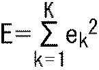


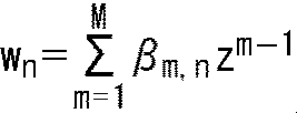


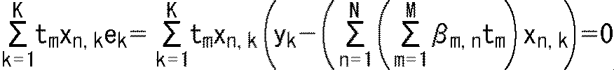


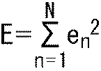
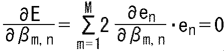


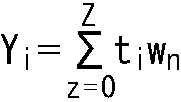
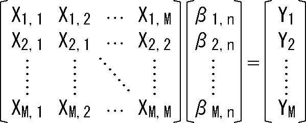
図30は、クラスタップのタップ構造の選択に用いる取得可能情報の例を示す図である。 <Example of obtainable information>
FIG. 30 is a diagram illustrating an example of acquirable information used for selecting a tap structure of a class tap.
このような階層画像符号化・階層画像復号(スケーラブル符号化・スケーラブル復号)において、スケーラビリティ(scalability)機能を有するパラメータは、任意である。例えば、空間解像度をそのパラメータとしてもよい(spatial scalability)。このスペーシャルスケーラビリティ(spatial scalability)の場合、レイヤ毎に画像の解像度が異なる。 <Scalable parameters>
In such hierarchical image encoding / hierarchical image decoding (scalable encoding / scalable decoding), parameters having a scalability function are arbitrary. For example, spatial resolution may be used as the parameter (spatial scalability). In the case of this spatial scalability, the resolution of the image is different for each layer.
ビデオセット1300は、画像データを処理する各種装置に組み込むことができる。例えば、ビデオセット1300は、テレビジョン装置1200(図49)、携帯電話機1220(図50)、記録再生装置1240(図51)、撮像装置1260(図52)等に組み込むことができる。ビデオセット1300を組み込むことにより、その装置は、上述した符号化装置11や復号装置12と同様の効果を得ることができる。 <Application example to equipment>
Video set 1300 can be incorporated into various devices that process image data. For example, the
なお、本明細書では、各種情報が、符号化データ(ビットストリーム)に多重化されて、符号化側から復号側へ伝送される例について説明したが、これら情報を伝送する手法はかかる例に限定されない。例えば、これら情報は、符号化データに多重化されることなく、符号化データと関連付けられた別個のデータとして伝送され又は記録されてもよい。ここで、「関連付ける」という用語は、例えば、符号化データに含まれる画像(スライス若しくはブロック等、画像の一部であってもよい)と当該画像に対応する情報とを復号時にリンクさせ得るようにすることを意味する。すなわち、この符号化データ(画像)に関連付けられた情報は、符号化データ(画像)とは別の伝送路上で伝送されるようにしてもよい。また、この符号化データ(画像)に関連付けられた情報は、符号化データ(画像)とは別の記録媒体(又は同一の記録媒体の別の記録エリア)に記録されるようにしてもよい。さらに、画像とその画像に対応する情報とが、例えば、複数フレーム、1フレーム、又はフレーム内の一部分等の任意の単位で互いに関連付けられるようにしてもよい。 <Others>
In this specification, an example in which various types of information are multiplexed with encoded data (bitstream) and transmitted from the encoding side to the decoding side has been described. However, the method of transmitting such information is such an example. It is not limited. For example, these pieces of information may be transmitted or recorded as separate data associated with the encoded data without being multiplexed with the encoded data. Here, the term “associate” means that, for example, an image (which may be a part of an image such as a slice or a block) included in the encoded data and information corresponding to the image can be linked at the time of decoding. That means That is, information associated with the encoded data (image) may be transmitted on a transmission path different from that of the encoded data (image). The information associated with the encoded data (image) may be recorded on a recording medium different from the encoded data (image) (or another recording area of the same recording medium). Furthermore, an image and information corresponding to the image may be associated with each other in an arbitrary unit such as a plurality of frames, one frame, or a part of the frame.
予測符号化の残差と予測画像とを加算することにより得られる第1の画像の処理対象画素を、複数のクラスのうちのいずれかのクラスに分類するクラス分類に用いられるクラスタップとなる画素を、前記第1の画像から選択することにより、前記クラスタップを構成するクラスタップ選択部と、
前記クラスタップを用いて、前記処理対象画素のクラス分類を行うクラス分類部と、
前記第1の画像に、前記処理対象画素のクラスに対応するフィルタ処理を行い、前記予測画像の予測に用いられる第2の画像を生成するフィルタ処理部と
を備え、
前記クラスタップ選択部は、前記クラスタップのタップ構造を、複数のタップ構造の中から選択されたタップ構造に更新する
画像処理装置。
<2>
前記フィルタ処理に関するフィルタ情報を伝送する伝送部をさらに備える
<1>に記載の画像処理装置。
<3>
前記フィルタ処理部は、
前記第1の画像の前記処理対象画素に対応する前記第2の画像の対応画素の画素値を求める予測演算に用いられる予測タップとなる画素を、前記第1の画像から選択することにより、前記予測タップを構成する予測タップ選択部と、
前記第1の画像に相当する生徒画像と、前記第1の画像に対応する元画像に相当する教師画像とを用いた学習により求められた、前記クラスごとの、前記予測演算に用いられるタップ係数のうちの、前記処理対象画素のクラスのタップ係数を取得するタップ係数取得部と、
前記処理対象画素のクラスのタップ係数と、前記処理対象画素の前記予測タップとを用いた前記予測演算を行うことにより、前記対応画素の画素値を求める演算部と
を有する
<2>に記載の画像処理装置。
<4>
前記フィルタ情報は、前記クラスごとのタップ係数を含む
<3>に記載の画像処理装置。
<5>
前記フィルタ情報は、前記複数のタップ構造の中から選択されたタップ構造を表すタップ構造情報を含む
<2>ないし<4>のいずれかに記載の画像処理装置。
<6>
前記複数のタップ構造それぞれを前記クラス分類に用いる適切さを表すタップ構造評価値に応じて、前記複数のタップ構造の中から、前記クラスタップのタップ構造を選択する選択部をさらに備える
<2>ないし<5>のいずれかに記載の画像処理装置。
<7>
前記予測符号化により得られる符号化データから取得可能な取得可能情報を用いて、前記複数のタップ構造の中から前記クラスタップのタップ構造を選択する選択規則に従い、前記複数のタップ構造の中から、前記クラスタップのタップ構造を選択するタップ構造選択部をさらに備える
<2>ないし<5>のいずれかに記載の画像処理装置。
<8>
前記フィルタ情報は、前記選択規則を含む
<7>に記載の画像処理装置。
<9>
前記取得可能情報は、前記第1の画像から得られる画像特徴量、及び、前記処理対象画素の予測符号化に関する符号化情報のうちの一方、又は、両方である
<7>又は<8>に記載の画像処理装置。
<10>
前記フィルタ情報は、前記クラスタップのタップ構造として、直前のタップ構造の更新時と同一のタップ構造を用いるかどうかを表すコピー情報を含む
<2>ないし<9>のいずれかに記載の画像処理装置。
<11>
前記フィルタ処理に関するフィルタ情報を受け取る受け取り部をさらに備える
<1>に記載の画像処理装置。
<12>
前記フィルタ処理部は、
前記第1の画像の前記処理対象画素に対応する前記第2の画像の対応画素の画素値を求める予測演算に用いられる予測タップとなる画素を、前記第1の画像から選択することにより、前記予測タップを構成する予測タップ選択部と、
前記第1の画像に相当する生徒画像と、前記第1の画像に対応する元画像に相当する教師画像とを用いた学習により求められた、前記クラスごとの、前記予測演算に用いられるタップ係数のうちの、前記処理対象画素のクラスのタップ係数を取得するタップ係数取得部と、
前記処理対象画素のクラスのタップ係数と、前記処理対象画素の前記予測タップとを用いた前記予測演算を行うことにより、前記対応画素の画素値を求める演算部と
を有する
<11>に記載の画像処理装置。
<13>
前記フィルタ情報は、前記クラスごとのタップ係数を含み、
前記タップ係数取得部は、前記フィルタ情報に含まれる前記クラスごとのタップ係数から、前記処理対象画素のクラスのタップ係数を取得する
<12>に記載の画像処理装置。
<14>
前記フィルタ情報は、前記複数のタップ構造の中から選択されたタップ構造を表すタップ構造情報を含み、
前記クラスタップ選択部は、前記クラスタップのタップ構造を、前記フィルタ情報に含まれる前記タップ構造情報が表すタップ構造に更新する
<11>ないし<13>のいずれかに記載の画像処理装置。
<15>
前記フィルタ情報は、前記複数のタップ構造の中から前記クラスタップのタップ構造を選択する選択規則を含み、
前記予測符号化により得られる符号化データから取得可能な取得可能情報を用いて、前記選択規則に従い、前記複数のタップ構造の中から、前記クラスタップのタップ構造を選択するタップ構造選択部をさらに備える
<11>ないし<13>のいずれかに記載の画像処理装置。
<16>
前記取得可能情報は、前記第1の画像から得られる画像特徴量、及び、前記処理対象画素の予測符号化に関する符号化情報のうちの一方、又は、両方である
<15>に記載の画像処理装置。
<17>
前記フィルタ情報は、前記クラスタップのタップ構造として、直前のタップ構造の更新時と同一のタップ構造を用いるかどうかを表すコピー情報を含み、
前記クラスタップ選択部は、前記フィルタ情報に含まれる前記コピー情報に応じて、前記クラスタップのタップ構造として、直前のタップ構造の更新時と同一のタップ構造を選択する
<11>ないし<16>に記載のいずれかに記載の画像処理装置。
<18>
前記フィルタ処理部は、ILF(In Loop Filter)を構成するDF(Deblocking Filter),SAO(Sample Adaptive Offset)、及び、ALF(Adaptive Loop Filter)のうちの1以上として機能する
<1>ないし<17>に記載のいずれかに記載の画像処理装置。
<19>
予測符号化の残差と予測画像とを加算することにより得られる第1の画像の処理対象画素を、複数のクラスのうちのいずれかのクラスに分類するクラス分類に用いられるクラスタップとなる画素を、前記第1の画像から選択することにより、前記クラスタップを構成することと、
前記クラスタップを用いて、前記処理対象画素のクラス分類を行うことと、
前記第1の画像に、前記処理対象画素のクラスに対応するフィルタ処理を行い、前記予測画像の予測に用いられる第2の画像を生成することと
を含み、
前記クラスタップのタップ構造を、複数のタップ構造の中から選択されたタップ構造に更新する
画像処理方法。 <1>
Pixel to be a class tap used for class classification that classifies a processing target pixel of the first image obtained by adding the prediction encoding residual and the prediction image into one of a plurality of classes By selecting from the first image, a class tap selection unit constituting the class tap,
A class classification unit that classifies the processing target pixel using the class tap;
A filter processing unit that performs a filtering process corresponding to the class of the processing target pixel on the first image, and generates a second image used for prediction of the predicted image;
The class tap selection unit updates the tap structure of the class tap to a tap structure selected from a plurality of tap structures.
<2>
The image processing apparatus according to <1>, further including a transmission unit configured to transmit filter information related to the filter processing.
<3>
The filter processing unit
By selecting, from the first image, a pixel to be a prediction tap used in a prediction calculation for obtaining a pixel value of a corresponding pixel of the second image corresponding to the processing target pixel of the first image, A prediction tap selection unit constituting the prediction tap;
Tap coefficient used for the prediction calculation for each class, obtained by learning using a student image corresponding to the first image and a teacher image corresponding to the original image corresponding to the first image A tap coefficient acquisition unit that acquires a tap coefficient of the class of the processing target pixel,
The calculation unit that obtains a pixel value of the corresponding pixel by performing the prediction calculation using the tap coefficient of the class of the processing target pixel and the prediction tap of the processing target pixel. Image processing device.
<4>
The image processing device according to <3>, wherein the filter information includes a tap coefficient for each class.
<5>
The image processing device according to any one of <2> to <4>, wherein the filter information includes tap structure information representing a tap structure selected from the plurality of tap structures.
<6>
A selection unit that selects a tap structure of the class tap from the plurality of tap structures according to a tap structure evaluation value that indicates appropriateness of using each of the plurality of tap structures for the class classification is further provided. <2> Or the image processing device according to any one of <5>.
<7>
Using the obtainable information obtainable from the encoded data obtained by the predictive coding, according to the selection rule for selecting the tap structure of the class tap from the plurality of tap structures, from among the plurality of tap structures The image processing apparatus according to any one of <2> to <5>, further including a tap structure selection unit that selects a tap structure of the class tap.
<8>
The image processing device according to <7>, wherein the filter information includes the selection rule.
<9>
The obtainable information is one or both of an image feature amount obtained from the first image and encoding information related to predictive encoding of the processing target pixel. <7> or <8> The image processing apparatus described.
<10>
The image processing according to any one of <2> to <9>, wherein the filter information includes copy information indicating whether or not the same tap structure as that used when updating the immediately preceding tap structure is used as the tap structure of the class tap. apparatus.
<11>
The image processing apparatus according to <1>, further including a receiving unit that receives filter information regarding the filter processing.
<12>
The filter processing unit
By selecting, from the first image, a pixel to be a prediction tap used in a prediction calculation for obtaining a pixel value of a corresponding pixel of the second image corresponding to the processing target pixel of the first image, A prediction tap selection unit constituting the prediction tap;
Tap coefficient used for the prediction calculation for each class, obtained by learning using a student image corresponding to the first image and a teacher image corresponding to the original image corresponding to the first image A tap coefficient acquisition unit that acquires a tap coefficient of the class of the processing target pixel,
The calculation unit that obtains the pixel value of the corresponding pixel by performing the prediction calculation using the tap coefficient of the class of the processing target pixel and the prediction tap of the processing target pixel. Image processing device.
<13>
The filter information includes a tap coefficient for each class,
The image processing device according to <12>, wherein the tap coefficient acquisition unit acquires a tap coefficient of a class of the processing target pixel from a tap coefficient for each class included in the filter information.
<14>
The filter information includes tap structure information representing a tap structure selected from the plurality of tap structures,
The image processing device according to any one of <11> to <13>, wherein the class tap selection unit updates the tap structure of the class tap to a tap structure represented by the tap structure information included in the filter information.
<15>
The filter information includes a selection rule for selecting a tap structure of the class tap from the plurality of tap structures,
A tap structure selection unit that selects a tap structure of the class tap from the plurality of tap structures according to the selection rule using the obtainable information obtainable from the encoded data obtained by the predictive coding. The image processing apparatus according to any one of <11> to <13>.
<16>
The image processing according to <15>, wherein the obtainable information is one or both of an image feature amount obtained from the first image and encoding information related to predictive encoding of the processing target pixel. apparatus.
<17>
The filter information includes copy information indicating whether to use the same tap structure as the previous tap structure update as the tap structure of the class tap,
The class tap selection unit selects, as the tap structure of the class tap, the same tap structure as that at the time of updating the immediately preceding tap structure according to the copy information included in the filter information. <11> to <16> An image processing apparatus according to any one of the above.
<18>
The filter processing unit functions as one or more of DF (Deblocking Filter), SAO (Sample Adaptive Offset), and ALF (Adaptive Loop Filter) constituting an ILF (In Loop Filter) <1> to <17 > The image processing apparatus according to any one of the above.
<19>
Pixel to be a class tap used for class classification that classifies a processing target pixel of the first image obtained by adding the prediction encoding residual and the prediction image into one of a plurality of classes Configuring the class tap by selecting from the first image;
Classifying the pixel to be processed using the class tap;
Performing filter processing corresponding to the class of the processing target pixel on the first image, and generating a second image used for prediction of the predicted image,
An image processing method for updating the tap structure of the class tap to a tap structure selected from a plurality of tap structures.
Claims (19)
- 予測符号化の残差と予測画像とを加算することにより得られる第1の画像の処理対象画素を、複数のクラスのうちのいずれかのクラスに分類するクラス分類に用いられるクラスタップとなる画素を、前記第1の画像から選択することにより、前記クラスタップを構成するクラスタップ選択部と、
前記クラスタップを用いて、前記処理対象画素のクラス分類を行うクラス分類部と、
前記第1の画像に、前記処理対象画素のクラスに対応するフィルタ処理を行い、前記予測画像の予測に用いられる第2の画像を生成するフィルタ処理部と
を備え、
前記クラスタップ選択部は、前記クラスタップのタップ構造を、複数のタップ構造の中から選択されたタップ構造に更新する
画像処理装置。 Pixel to be a class tap used for class classification that classifies a processing target pixel of the first image obtained by adding the prediction encoding residual and the prediction image into one of a plurality of classes By selecting from the first image, a class tap selection unit constituting the class tap,
A class classification unit that classifies the processing target pixel using the class tap;
A filter processing unit that performs a filtering process corresponding to the class of the processing target pixel on the first image, and generates a second image used for prediction of the predicted image;
The class tap selection unit updates the tap structure of the class tap to a tap structure selected from a plurality of tap structures. - 前記フィルタ処理に関するフィルタ情報を伝送する伝送部をさらに備える
請求項1に記載の画像処理装置。 The image processing apparatus according to claim 1, further comprising: a transmission unit that transmits filter information related to the filter processing. - 前記フィルタ処理部は、
前記第1の画像の前記処理対象画素に対応する前記第2の画像の対応画素の画素値を求める予測演算に用いられる予測タップとなる画素を、前記第1の画像から選択することにより、前記予測タップを構成する予測タップ選択部と、
前記第1の画像に相当する生徒画像と、前記第1の画像に対応する元画像に相当する教師画像とを用いた学習により求められた、前記クラスごとの、前記予測演算に用いられるタップ係数のうちの、前記処理対象画素のクラスのタップ係数を取得するタップ係数取得部と、
前記処理対象画素のクラスのタップ係数と、前記処理対象画素の前記予測タップとを用いた前記予測演算を行うことにより、前記対応画素の画素値を求める演算部と
を有する
請求項2に記載の画像処理装置。 The filter processing unit
By selecting, from the first image, a pixel to be a prediction tap used in a prediction calculation for obtaining a pixel value of a corresponding pixel of the second image corresponding to the processing target pixel of the first image, A prediction tap selection unit constituting the prediction tap;
Tap coefficient used for the prediction calculation for each class, obtained by learning using a student image corresponding to the first image and a teacher image corresponding to the original image corresponding to the first image A tap coefficient acquisition unit that acquires a tap coefficient of the class of the processing target pixel,
The calculation unit according to claim 2, further comprising: a calculation unit that calculates a pixel value of the corresponding pixel by performing the prediction calculation using the tap coefficient of the class of the processing target pixel and the prediction tap of the processing target pixel. Image processing device. - 前記フィルタ情報は、前記クラスごとのタップ係数を含む
請求項3に記載の画像処理装置。 The image processing apparatus according to claim 3, wherein the filter information includes a tap coefficient for each class. - 前記フィルタ情報は、前記複数のタップ構造の中から選択されたタップ構造を表すタップ構造情報を含む
請求項2に記載の画像処理装置。 The image processing apparatus according to claim 2, wherein the filter information includes tap structure information representing a tap structure selected from the plurality of tap structures. - 前記複数のタップ構造それぞれを前記クラス分類に用いる適切さを表すタップ構造評価値に応じて、前記複数のタップ構造の中から、前記クラスタップのタップ構造を選択する選択部をさらに備える
請求項2に記載の画像処理装置。 The apparatus according to claim 2, further comprising: a selection unit that selects a tap structure of the class tap from the plurality of tap structures according to a tap structure evaluation value representing an appropriateness of using each of the plurality of tap structures for the class classification. An image processing apparatus according to 1. - 前記予測符号化により得られる符号化データから取得可能な取得可能情報を用いて、前記複数のタップ構造の中から前記クラスタップのタップ構造を選択する選択規則に従い、前記複数のタップ構造の中から、前記クラスタップのタップ構造を選択するタップ構造選択部をさらに備える
請求項2に記載の画像処理装置。 Using the obtainable information obtainable from the encoded data obtained by the predictive coding, according to the selection rule for selecting the tap structure of the class tap from the plurality of tap structures, from among the plurality of tap structures The image processing apparatus according to claim 2, further comprising a tap structure selection unit that selects a tap structure of the class tap. - 前記フィルタ情報は、前記選択規則を含む
請求項7に記載の画像処理装置。 The image processing apparatus according to claim 7, wherein the filter information includes the selection rule. - 前記取得可能情報は、前記第1の画像から得られる画像特徴量、及び、前記処理対象画素の予測符号化に関する符号化情報のうちの一方、又は、両方である
請求項7に記載の画像処理装置。 The image processing according to claim 7, wherein the acquirable information is one or both of an image feature amount obtained from the first image and encoding information related to predictive encoding of the processing target pixel. apparatus. - 前記フィルタ情報は、前記クラスタップのタップ構造として、直前のタップ構造の更新時と同一のタップ構造を用いるかどうかを表すコピー情報を含む
請求項2に記載の画像処理装置。 The image processing apparatus according to claim 2, wherein the filter information includes copy information indicating whether the same tap structure as that used when updating the immediately preceding tap structure is used as the tap structure of the class tap. - 前記フィルタ処理に関するフィルタ情報を受け取る受け取り部をさらに備える
請求項1に記載の画像処理装置。 The image processing apparatus according to claim 1, further comprising a receiving unit that receives filter information related to the filter processing. - 前記フィルタ処理部は、
前記第1の画像の前記処理対象画素に対応する前記第2の画像の対応画素の画素値を求める予測演算に用いられる予測タップとなる画素を、前記第1の画像から選択することにより、前記予測タップを構成する予測タップ選択部と、
前記第1の画像に相当する生徒画像と、前記第1の画像に対応する元画像に相当する教師画像とを用いた学習により求められた、前記クラスごとの、前記予測演算に用いられるタップ係数のうちの、前記処理対象画素のクラスのタップ係数を取得するタップ係数取得部と、
前記処理対象画素のクラスのタップ係数と、前記処理対象画素の前記予測タップとを用いた前記予測演算を行うことにより、前記対応画素の画素値を求める演算部と
を有する
請求項11に記載の画像処理装置。 The filter processing unit
By selecting, from the first image, a pixel to be a prediction tap used in a prediction calculation for obtaining a pixel value of a corresponding pixel of the second image corresponding to the processing target pixel of the first image, A prediction tap selection unit constituting the prediction tap;
Tap coefficient used for the prediction calculation for each class, obtained by learning using a student image corresponding to the first image and a teacher image corresponding to the original image corresponding to the first image A tap coefficient acquisition unit that acquires a tap coefficient of the class of the processing target pixel,
The calculation unit that obtains a pixel value of the corresponding pixel by performing the prediction calculation using the tap coefficient of the class of the processing target pixel and the prediction tap of the processing target pixel. Image processing device. - 前記フィルタ情報は、前記クラスごとのタップ係数を含み、
前記タップ係数取得部は、前記フィルタ情報に含まれる前記クラスごとのタップ係数から、前記処理対象画素のクラスのタップ係数を取得する
請求項12に記載の画像処理装置。 The filter information includes a tap coefficient for each class,
The image processing device according to claim 12, wherein the tap coefficient acquisition unit acquires a tap coefficient of a class of the processing target pixel from a tap coefficient for each class included in the filter information. - 前記フィルタ情報は、前記複数のタップ構造の中から選択されたタップ構造を表すタップ構造情報を含み、
前記クラスタップ選択部は、前記クラスタップのタップ構造を、前記フィルタ情報に含まれる前記タップ構造情報が表すタップ構造に更新する
請求項11に記載の画像処理装置。 The filter information includes tap structure information representing a tap structure selected from the plurality of tap structures,
The image processing device according to claim 11, wherein the class tap selection unit updates the tap structure of the class tap to a tap structure represented by the tap structure information included in the filter information. - 前記フィルタ情報は、前記複数のタップ構造の中から前記クラスタップのタップ構造を選択する選択規則を含み、
前記予測符号化により得られる符号化データから取得可能な取得可能情報を用いて、前記選択規則に従い、前記複数のタップ構造の中から、前記クラスタップのタップ構造を選択するタップ構造選択部をさらに備える
請求項11に記載の画像処理装置。 The filter information includes a selection rule for selecting a tap structure of the class tap from the plurality of tap structures,
A tap structure selection unit that selects a tap structure of the class tap from the plurality of tap structures according to the selection rule using the obtainable information obtainable from the encoded data obtained by the predictive coding. The image processing apparatus according to claim 11. - 前記取得可能情報は、前記第1の画像から得られる画像特徴量、及び、前記処理対象画素の予測符号化に関する符号化情報のうちの一方、又は、両方である
請求項15に記載の画像処理装置。 The image processing according to claim 15, wherein the acquirable information is one or both of an image feature amount obtained from the first image and encoding information related to predictive encoding of the processing target pixel. apparatus. - 前記フィルタ情報は、前記クラスタップのタップ構造として、直前のタップ構造の更新時と同一のタップ構造を用いるかどうかを表すコピー情報を含み、
前記クラスタップ選択部は、前記フィルタ情報に含まれる前記コピー情報に応じて、前記クラスタップのタップ構造として、直前のタップ構造の更新時と同一のタップ構造を選択する
請求項11に記載の画像処理装置。 The filter information includes copy information indicating whether to use the same tap structure as the previous tap structure update as the tap structure of the class tap,
The image according to claim 11, wherein the class tap selection unit selects, as the tap structure of the class tap, the same tap structure at the time of updating the immediately preceding tap structure according to the copy information included in the filter information. Processing equipment. - 前記フィルタ処理部は、ILF(In Loop Filter)を構成するDF(Deblocking Filter),SAO(Sample Adaptive Offset)、及び、ALF(Adaptive Loop Filter)のうちの1以上として機能する
請求項1に記載の画像処理装置。 The filter processing unit functions as one or more of DF (Deblocking Filter), SAO (Sample Adaptive Offset), and ALF (Adaptive Loop Filter) constituting an ILF (In Loop Filter). Image processing device. - 予測符号化の残差と予測画像とを加算することにより得られる第1の画像の処理対象画素を、複数のクラスのうちのいずれかのクラスに分類するクラス分類に用いられるクラスタップとなる画素を、前記第1の画像から選択することにより、前記クラスタップを構成することと、
前記クラスタップを用いて、前記処理対象画素のクラス分類を行うことと、
前記第1の画像に、前記処理対象画素のクラスに対応するフィルタ処理を行い、前記予測画像の予測に用いられる第2の画像を生成することと
を含み、
前記クラスタップのタップ構造を、複数のタップ構造の中から選択されたタップ構造に更新する
画像処理方法。 Pixel to be a class tap used for class classification that classifies a processing target pixel of the first image obtained by adding the prediction encoding residual and the prediction image into one of a plurality of classes Configuring the class tap by selecting from the first image;
Classifying the pixel to be processed using the class tap;
Performing filter processing corresponding to the class of the processing target pixel on the first image, and generating a second image used for prediction of the predicted image,
An image processing method for updating the tap structure of the class tap to a tap structure selected from a plurality of tap structures.
Priority Applications (10)
| Application Number | Priority Date | Filing Date | Title |
|---|---|---|---|
| RU2019120747A RU2019120747A (en) | 2017-01-12 | 2017-12-28 | IMAGE PROCESSING DEVICE AND IMAGE PROCESSING METHOD |
| BR112019013976-1A BR112019013976A2 (en) | 2017-01-12 | 2017-12-28 | APPARATUS AND IMAGE PROCESSING METHOD. |
| CN201780082531.1A CN110169063B (en) | 2017-01-12 | 2017-12-28 | Image processing apparatus, image processing method, and program |
| AU2017393149A AU2017393149A1 (en) | 2017-01-12 | 2017-12-28 | Image processing device and image processing method |
| KR1020197019011A KR102477784B1 (en) | 2017-01-12 | 2017-12-28 | Image processing device and image processing method |
| JP2018561335A JP7047776B2 (en) | 2017-01-12 | 2017-12-28 | Encoding device and coding method, and decoding device and decoding method |
| CA3048382A CA3048382A1 (en) | 2017-01-12 | 2017-12-28 | Image processing apparatus and image processing method |
| US16/468,486 US11190808B2 (en) | 2017-01-12 | 2017-12-28 | Image processing apparatus and image processing method |
| CN202210114315.3A CN114520915A (en) | 2017-01-12 | 2017-12-28 | Image processing apparatus, image processing method, and computer-readable recording medium |
| EP17891477.6A EP3570543A4 (en) | 2017-01-12 | 2017-12-28 | Image processing device and image processing method |
Applications Claiming Priority (2)
| Application Number | Priority Date | Filing Date | Title |
|---|---|---|---|
| JP2017-003467 | 2017-01-12 | ||
| JP2017003467 | 2017-01-12 |
Publications (1)
| Publication Number | Publication Date |
|---|---|
| WO2018131524A1 true WO2018131524A1 (en) | 2018-07-19 |
Family
ID=62839867
Family Applications (1)
| Application Number | Title | Priority Date | Filing Date |
|---|---|---|---|
| PCT/JP2017/047374 WO2018131524A1 (en) | 2017-01-12 | 2017-12-28 | Image processing device and image processing method |
Country Status (10)
| Country | Link |
|---|---|
| US (1) | US11190808B2 (en) |
| EP (1) | EP3570543A4 (en) |
| JP (1) | JP7047776B2 (en) |
| KR (1) | KR102477784B1 (en) |
| CN (2) | CN110169063B (en) |
| AU (1) | AU2017393149A1 (en) |
| BR (1) | BR112019013976A2 (en) |
| CA (1) | CA3048382A1 (en) |
| RU (1) | RU2019120747A (en) |
| WO (1) | WO2018131524A1 (en) |
Cited By (2)
| Publication number | Priority date | Publication date | Assignee | Title |
|---|---|---|---|---|
| JP2022511310A (en) * | 2018-11-12 | 2022-01-31 | サムスン エレクトロニクス カンパニー リミテッド | Display device and its control method |
| JP7467676B2 (en) | 2021-03-18 | 2024-04-15 | テンセント・アメリカ・エルエルシー | METHOD AND APPARATUS FOR VIDEO CODING - Patent application |
Families Citing this family (4)
| Publication number | Priority date | Publication date | Assignee | Title |
|---|---|---|---|---|
| CN111801941B (en) * | 2018-03-09 | 2022-04-12 | 华为技术有限公司 | Method and apparatus for image filtering using adaptive multiplier coefficients |
| CN113965764B (en) * | 2020-07-21 | 2023-04-07 | Oppo广东移动通信有限公司 | Image encoding method, image decoding method and related device |
| US11706461B2 (en) * | 2021-03-18 | 2023-07-18 | Tencent America LLC | Method and apparatus for video coding |
| CN113963321B (en) * | 2021-10-27 | 2023-08-04 | 阿波罗智联(北京)科技有限公司 | Image processing method, device, electronic equipment and medium |
Citations (5)
| Publication number | Priority date | Publication date | Assignee | Title |
|---|---|---|---|---|
| JP2001285881A (en) * | 2000-04-03 | 2001-10-12 | Sony Corp | Digital information converter and method, and image information converter and method |
| WO2010146771A1 (en) * | 2009-06-19 | 2010-12-23 | 三菱電機株式会社 | Image encoding device, image decoding device, image encoding method, and image decoding method |
| JP2012235407A (en) * | 2011-05-09 | 2012-11-29 | Sony Corp | Image processing apparatus and image processing method |
| WO2014023183A1 (en) | 2012-08-07 | 2014-02-13 | 歌尔声学股份有限公司 | Voice enhancing method and apparatus applied to cell phone |
| JP5485983B2 (en) | 2009-04-03 | 2014-05-07 | パナソニック株式会社 | Moving picture coding method, moving picture decoding method, moving picture coding apparatus, and moving picture decoding apparatus |
Family Cites Families (13)
| Publication number | Priority date | Publication date | Assignee | Title |
|---|---|---|---|---|
| JP3596770B2 (en) | 2001-12-28 | 2004-12-02 | ソニー株式会社 | Storage device, data processing device and data processing method, program and recording medium, and data processing system |
| US7630576B2 (en) * | 2004-02-19 | 2009-12-08 | Sony Corporation | Signal processing apparatus and method, and command-sequence data structure |
| JP4517300B2 (en) | 2006-01-06 | 2010-08-04 | ソニー株式会社 | Display device, display method, learning device, learning method, and program |
| JP4835949B2 (en) * | 2007-12-21 | 2011-12-14 | ソニー株式会社 | Image processing apparatus and method, learning apparatus and method, program, and recording medium |
| CN101616324B (en) | 2009-07-28 | 2011-06-08 | 谭洪舟 | Blocky effect removal device for compression coded image |
| TWI600318B (en) * | 2010-05-18 | 2017-09-21 | Sony Corp | Image processing apparatus and image processing method |
| CN102948151B (en) * | 2010-06-17 | 2016-08-03 | 夏普株式会社 | Image filtering device, decoding apparatus and code device |
| ES2715782T3 (en) * | 2011-04-21 | 2019-06-06 | Hfi Innovation Inc | Procedure and apparatus for improved loop filtering |
| EP2708027B1 (en) * | 2011-05-10 | 2019-12-25 | MediaTek Inc. | Method and apparatus for reduction of in-loop filter buffer |
| SG10201408716TA (en) | 2011-06-28 | 2015-02-27 | Samsung Electronics Co Ltd | Video Encoding Method Using Offset Adjustments According To Pixel Classification And Apparatus Therefor, Video Decoding Method And Apparatus Therefor |
| JP2013085113A (en) * | 2011-10-07 | 2013-05-09 | Sony Corp | Image processing device and method |
| US9357235B2 (en) | 2011-10-13 | 2016-05-31 | Qualcomm Incorporated | Sample adaptive offset merged with adaptive loop filter in video coding |
| JP2014194706A (en) | 2013-03-29 | 2014-10-09 | Sony Corp | Image processor, image processing method and program |
-
2017
- 2017-12-28 WO PCT/JP2017/047374 patent/WO2018131524A1/en unknown
- 2017-12-28 EP EP17891477.6A patent/EP3570543A4/en not_active Withdrawn
- 2017-12-28 AU AU2017393149A patent/AU2017393149A1/en not_active Abandoned
- 2017-12-28 KR KR1020197019011A patent/KR102477784B1/en active IP Right Grant
- 2017-12-28 CA CA3048382A patent/CA3048382A1/en not_active Abandoned
- 2017-12-28 CN CN201780082531.1A patent/CN110169063B/en active Active
- 2017-12-28 US US16/468,486 patent/US11190808B2/en active Active
- 2017-12-28 CN CN202210114315.3A patent/CN114520915A/en not_active Withdrawn
- 2017-12-28 JP JP2018561335A patent/JP7047776B2/en active Active
- 2017-12-28 BR BR112019013976-1A patent/BR112019013976A2/en not_active Application Discontinuation
- 2017-12-28 RU RU2019120747A patent/RU2019120747A/en not_active Application Discontinuation
Patent Citations (5)
| Publication number | Priority date | Publication date | Assignee | Title |
|---|---|---|---|---|
| JP2001285881A (en) * | 2000-04-03 | 2001-10-12 | Sony Corp | Digital information converter and method, and image information converter and method |
| JP5485983B2 (en) | 2009-04-03 | 2014-05-07 | パナソニック株式会社 | Moving picture coding method, moving picture decoding method, moving picture coding apparatus, and moving picture decoding apparatus |
| WO2010146771A1 (en) * | 2009-06-19 | 2010-12-23 | 三菱電機株式会社 | Image encoding device, image decoding device, image encoding method, and image decoding method |
| JP2012235407A (en) * | 2011-05-09 | 2012-11-29 | Sony Corp | Image processing apparatus and image processing method |
| WO2014023183A1 (en) | 2012-08-07 | 2014-02-13 | 歌尔声学股份有限公司 | Voice enhancing method and apparatus applied to cell phone |
Non-Patent Citations (1)
| Title |
|---|
| See also references of EP3570543A4 |
Cited By (4)
| Publication number | Priority date | Publication date | Assignee | Title |
|---|---|---|---|---|
| JP2022511310A (en) * | 2018-11-12 | 2022-01-31 | サムスン エレクトロニクス カンパニー リミテッド | Display device and its control method |
| JP7214845B2 (en) | 2018-11-12 | 2023-01-30 | サムスン エレクトロニクス カンパニー リミテッド | Display device and its control method |
| US11968382B2 (en) | 2018-11-12 | 2024-04-23 | Samsung Electronics Co., Ltd. | Display apparatus and method of controlling the same |
| JP7467676B2 (en) | 2021-03-18 | 2024-04-15 | テンセント・アメリカ・エルエルシー | METHOD AND APPARATUS FOR VIDEO CODING - Patent application |
Also Published As
| Publication number | Publication date |
|---|---|
| CN110169063B (en) | 2022-03-01 |
| US20200077120A1 (en) | 2020-03-05 |
| EP3570543A4 (en) | 2019-12-25 |
| BR112019013976A2 (en) | 2020-03-03 |
| CA3048382A1 (en) | 2018-07-19 |
| RU2019120747A (en) | 2021-01-15 |
| AU2017393149A1 (en) | 2019-07-25 |
| US11190808B2 (en) | 2021-11-30 |
| KR20190105578A (en) | 2019-09-17 |
| CN114520915A (en) | 2022-05-20 |
| EP3570543A1 (en) | 2019-11-20 |
| KR102477784B1 (en) | 2022-12-15 |
| CN110169063A (en) | 2019-08-23 |
| JPWO2018131524A1 (en) | 2019-11-07 |
| JP7047776B2 (en) | 2022-04-05 |
Similar Documents
| Publication | Publication Date | Title |
|---|---|---|
| AU2022203068B2 (en) | Apparatus and method for image processing | |
| JP6977719B2 (en) | Coding device and coding method, and decoding device and decoding method | |
| JP7047776B2 (en) | Encoding device and coding method, and decoding device and decoding method | |
| WO2017191749A1 (en) | Image processing device, and image processing method | |
| JP6883219B2 (en) | Coding device and coding method, and system | |
| CN105900424B (en) | Decoding apparatus, coding/decoding method, code device and coding method | |
| US20190020877A1 (en) | Image processing apparatus and method | |
| WO2018131515A1 (en) | Image processing device and image processing method | |
| EP3675490A1 (en) | Image processing device and image processing method | |
| WO2018173873A1 (en) | Coding device and coding method, and decoding device and decoding method | |
| WO2018051811A1 (en) | Image processing device and image processing method | |
| WO2018168484A1 (en) | Coding device, coding method, decoding device, and decoding method | |
| US11423578B2 (en) | Encoding device, encoding method, decoding device, and decoding method |
Legal Events
| Date | Code | Title | Description |
|---|---|---|---|
| 121 | Ep: the epo has been informed by wipo that ep was designated in this application |
Ref document number: 17891477 Country of ref document: EP Kind code of ref document: A1 |
|
| ENP | Entry into the national phase |
Ref document number: 2018561335 Country of ref document: JP Kind code of ref document: A |
|
| ENP | Entry into the national phase |
Ref document number: 3048382 Country of ref document: CA |
|
| ENP | Entry into the national phase |
Ref document number: 20197019011 Country of ref document: KR Kind code of ref document: A |
|
| NENP | Non-entry into the national phase |
Ref country code: DE |
|
| REG | Reference to national code |
Ref country code: BR Ref legal event code: B01A Ref document number: 112019013976 Country of ref document: BR |
|
| ENP | Entry into the national phase |
Ref document number: 2017393149 Country of ref document: AU Date of ref document: 20171228 Kind code of ref document: A |
|
| ENP | Entry into the national phase |
Ref document number: 2017891477 Country of ref document: EP Effective date: 20190812 |
|
| ENP | Entry into the national phase |
Ref document number: 112019013976 Country of ref document: BR Kind code of ref document: A2 Effective date: 20190705 |