WO2018128151A1 - 共振型限流回路 - Google Patents
共振型限流回路 Download PDFInfo
- Publication number
- WO2018128151A1 WO2018128151A1 PCT/JP2017/046984 JP2017046984W WO2018128151A1 WO 2018128151 A1 WO2018128151 A1 WO 2018128151A1 JP 2017046984 W JP2017046984 W JP 2017046984W WO 2018128151 A1 WO2018128151 A1 WO 2018128151A1
- Authority
- WO
- WIPO (PCT)
- Prior art keywords
- magnetic field
- magnetic
- current
- value
- circuit
- Prior art date
- Legal status (The legal status is an assumption and is not a legal conclusion. Google has not performed a legal analysis and makes no representation as to the accuracy of the status listed.)
- Ceased
Links
Images







Classifications
-
- H—ELECTRICITY
- H01—ELECTRIC ELEMENTS
- H01F—MAGNETS; INDUCTANCES; TRANSFORMERS; SELECTION OF MATERIALS FOR THEIR MAGNETIC PROPERTIES
- H01F1/00—Magnets or magnetic bodies characterised by the magnetic materials therefor; Selection of materials for their magnetic properties
- H01F1/01—Magnets or magnetic bodies characterised by the magnetic materials therefor; Selection of materials for their magnetic properties of inorganic materials
- H01F1/03—Magnets or magnetic bodies characterised by the magnetic materials therefor; Selection of materials for their magnetic properties of inorganic materials characterised by their coercivity
- H01F1/12—Magnets or magnetic bodies characterised by the magnetic materials therefor; Selection of materials for their magnetic properties of inorganic materials characterised by their coercivity of soft-magnetic materials
- H01F1/14—Magnets or magnetic bodies characterised by the magnetic materials therefor; Selection of materials for their magnetic properties of inorganic materials characterised by their coercivity of soft-magnetic materials metals or alloys
- H01F1/147—Alloys characterised by their composition
-
- H—ELECTRICITY
- H01—ELECTRIC ELEMENTS
- H01F—MAGNETS; INDUCTANCES; TRANSFORMERS; SELECTION OF MATERIALS FOR THEIR MAGNETIC PROPERTIES
- H01F37/00—Fixed inductances not covered by group H01F17/00
-
- H—ELECTRICITY
- H02—GENERATION; CONVERSION OR DISTRIBUTION OF ELECTRIC POWER
- H02H—EMERGENCY PROTECTIVE CIRCUIT ARRANGEMENTS
- H02H9/00—Emergency protective circuit arrangements for limiting excess current or voltage without disconnection
- H02H9/02—Emergency protective circuit arrangements for limiting excess current or voltage without disconnection responsive to excess current
Definitions
- the present invention relates to a resonance type current limiting circuit, and more particularly to a resonance type current limiting circuit including a reactance type current limiting device.
- a current limiter is known as a device for suppressing such a large current when a short circuit accident occurs.
- the demand for current limiters is expected to increase in the future with the increase in power capacity and the spread of distributed power sources in recent years.
- the specific configuration of the current limiting device is described in Patent Documents 1 to 4, for example.
- the current limiting device described in Patent Documents 1 and 2 has a configuration in which a reactor is connected to a bridge circuit composed of a thyristor and a diode.
- the current limiter described in Patent Document 3 has a configuration in which a series resonant circuit and a parallel resonant circuit are combined.
- the current limiting device described in Patent Document 4 has a configuration in which a magnetic bias is applied to a saturable DC reactor using a DC power supply.
- JP 49-50448 A Japanese Patent Laid-Open No. 9-285012 JP 2010-17016 A JP 2002-291150 A
- the current limiters described in Patent Documents 1 to 4 have a large number of elements and a complicated apparatus configuration.
- the current limiting device described in Patent Document 3 requires a separate filter circuit for suppressing noise, which further complicates the circuit configuration.
- the current limiter described in Patent Document 4 always requires a DC power source for applying a magnetic bias, and there is a problem that it does not function as a current limiter when the DC power source is lost.
- the conventional current limiter since the conventional current limiter has a complicated device configuration, there is a problem that not only it is difficult to ensure reliability but also a heavy maintenance burden. Moreover, it is difficult to obtain a sufficient response speed due to the complexity of the device configuration.
- the current limiter it is desirable for the current limiter to have as low an impedance as possible during normal operation. However, with the current limiter alone, it may be difficult to sufficiently reduce the impedance during normal operation.
- an object of the present invention is to provide a reliable current limiting circuit having a simple device configuration and having a reduced impedance during normal operation.
- a current limiting circuit is a current limiting circuit for limiting a current supplied from an AC power source, and includes a current limiting device including a magnetic core and a coil wound around the magnetic core, and the current limiting device in series. And a connected capacitor.
- the magnetic characteristics of the magnetic core are as follows. Is a first value, and in a second magnetic field region that is stronger than the first magnetic field strength, a magnetic flux density with respect to the magnetic field or a differential value of magnetization is a second value that is larger than the first value. is there.
- the coil and the capacitor constitute an LC resonance circuit that resonates in the frequency band of the AC power source when the magnetic field applied to the magnetic core is in the first magnetic field region.
- the reactance when the current flowing through the coil is equal to or less than the predetermined value, the reactance is small because the operation is performed in the first magnetic field region.
- the reactance increases because it operates.
- the current limiting operation can be performed when the current exceeds the predetermined value without substantially becoming a load on the power system or the electric circuit. And since it is the simple apparatus structure which wound the coil around the magnetic core, it becomes possible to provide a low-cost and highly reliable current limiter.
- the LC resonance circuit when the magnetic field applied to the magnetic core is in the first magnetic field region, the LC resonance circuit resonates in the frequency band of the AC power supply, so that the impedance during normal operation can be greatly reduced.
- a metamagnetic material, a perminbar characteristic material, or a synthetic antiferromagnetic material may be used as a material constituting the magnetic core.
- the resonance frequency of the LC resonance circuit when the magnetic field applied to the magnetic core is the second magnetic field region is different from the frequency band of the AC power supply. According to this, since the impedance at the time of abnormality becomes larger, more effective current limiting operation can be performed.
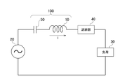
- FIG. 1 is a circuit diagram of an electric circuit using a current limiting circuit 100 according to an embodiment of the present invention.
- FIG. 2 is another circuit diagram of an electric circuit using the current limiting circuit 100.
- FIG. 3 is a diagram illustrating an example of a specific configuration of the current limiter 10.
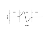
- FIG. 4 is a graph showing the magnetic characteristics of the magnetic material used for the magnetic core 11.
- FIG. 5 is a graph showing the magnetic characteristics of the magnetic material used for the magnetic core 11 and shows only the first quadrant (I).
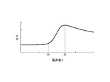
- FIG. 6 is a graph showing the relationship between the current I flowing through the coil 12 of the current limiter 10 and the inductance L.
- FIG. 7 is a graph showing the relationship between the voltage V applied to the coil 12 and the current I flowing through the coil 12.
- FIG. 1 is a circuit diagram of an electric circuit using a current limiting circuit 100 according to an embodiment of the present invention.
- FIG. 2 is another circuit diagram of an electric circuit using the current limiting circuit 100.
- FIG. 3 is a
- FIG. 8 is another graph showing the magnetic characteristics of the magnetic material used for the magnetic core 11.
- FIG. 9 is a graph showing a differential value of the characteristic shown in FIG.
- FIG. 10 is a graph showing the twice differential value of the characteristic shown in FIG.
- FIG. 11 is a graph showing the relationship between the current I flowing through the coil 12 and the value of B / H.
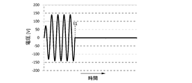
- FIG. 12 is a simulation result showing a voltage waveform applied to the load 30.
- FIG. 13 is a simulation result showing a waveform of a current flowing through the current limiter 10.
- FIG. 14 is a simulation result showing a waveform of a current flowing through the linear reactor when a normal linear reactor is used instead of the current limiter 10.
- FIG. 1 is a circuit diagram of an electric circuit using a current limiting circuit 100 according to an embodiment of the present invention.
- the electric circuit shown in FIG. 1 includes a current limiting circuit 100 and a load 30 connected in series to an AC power supply 20.
- the AC power source 20 is, for example, a commercial power source
- the load 30 is various electric devices that operate with power supplied from the AC power source 20.
- the current limiting circuit 100 according to the present embodiment is connected in series between the AC power supply 20 and the load 30 and plays a role of suppressing a large current that flows when the load 30 causes a short circuit accident.
- the circuit breaker 40 may be connected in series with the load 30. If the circuit breaker 40 is used, when the load 30 causes a short circuit accident, the circuit breaker 40 can perform a circuit breaking operation in a state where a large current is suppressed by the current limiting circuit 100.
- the current limiting circuit 100 constitutes an LC resonance circuit in which a reactor type current limiting device 10 and a capacitor 50 are connected in series.
- the resonance frequency of the LC resonance circuit during normal operation is set in the frequency band of the AC power supply 20, and therefore the impedance of the current limiting circuit 100 during normal operation is very small.
- the resonance frequency of the LC resonance circuit does not need to be completely coincident with the frequency of the AC power supply 20, but is set near the frequency of the AC power supply 20 so that the impedance of the current limiting circuit 100 is sufficiently small during normal operation. There is a need.
- it is preferable that the resonance frequency of the LC resonance circuit at the time of abnormality in which a short circuit accident occurs is different from the frequency band of the AC power supply 20.
- Current limiting device 10 is a simple reactor. Although details will be described later, the reactance of the current limiter 10 is sufficiently small during normal operation in which the current I is a predetermined value or less. Moreover, as described above, since the LC resonance circuit resonates during normal operation, the impedance given to the electric circuit is very small. On the other hand, when the current I exceeds a predetermined value, the reactance of the current limiter 10 is significantly increased. Thereby, since it acts as a large impedance for the AC power supply 20, an increase in the current I is suppressed. Such a change in reactance is due to a change in the magnetic field applied to the magnetic core of the reactor (the principle of electromagnetic induction) and occurs spontaneously in response to a change in the current I. Therefore, an element for detecting the current value Etc. are not necessary.
- FIG. 3 is a diagram illustrating an example of a specific configuration of the current limiter 10 used in the present embodiment.
- a current limiter 10 shown in FIG. 3 includes a toroidal magnetic core 11 and a coil 12 wound around the magnetic core 11.
- the coil 12 is preferably made of a coated conductor using copper (Cu) having a low resistance value as a core material.
- the toroidal magnetic core 11 forms a closed magnetic circuit.
- a current I flows through the coil 12 wound around the magnetic core 11
- a magnetic flux that circulates around the toroidal magnetic core 11 is generated.
- the magnetic permeability of the magnetic core 11 is sufficiently low, and therefore the reactance generated is small.
- the current I exceeds the predetermined value, the magnetic permeability of the magnetic core 11 increases abruptly, and the reactance also increases abruptly.
- the magnetic material described in detail below is used as the material of the magnetic core 11.
- FIG. 4 is a graph showing the magnetic characteristics of the magnetic material used for the magnetic core 11, the horizontal axis (X axis) being the first axis shows the magnetic field H, and the vertical axis (Y axis) being the second axis is the magnetization. M is shown.
- symbol A indicates the magnetic property of the magnetic core 11
- symbol SM indicates the magnetic property of a general soft magnetic material
- symbol HM indicates the magnetic property of a general hard magnetic material.
- a general soft magnetic material has a high magnetic permeability in a low magnetic field region and is easily magnetized.
- magnetic saturation occurs. It shows the property of being hardly magnetized.
- the differential value of the magnetization M with respect to the magnetic field H is large in the magnetic field region where the magnetic saturation is not performed, and the differential value of the magnetization M with respect to the magnetic field H is small in the magnetic field region where the magnetic saturation occurs.
- the characteristic curve indicated by symbol SM passes through the graph origin or the vicinity thereof. Therefore, the characteristic curve indicated by symbol SM appears in the first quadrant (I) and the third quadrant (III) of the graph, and does not substantially appear in the second quadrant (II) and the fourth quadrant (IV).
- HM As shown by reference numeral HM in FIG. 4, a general hard magnetic material has a large hysteresis, and a magnetized state is maintained even if the magnetic field is zero. For this reason, the characteristic curve indicated by symbol HM appears in all of the first quadrant (I) to the fourth quadrant (IV) of the graph.
- the magnetic material used for the magnetic core 11 in the present embodiment is in the low magnetic field region as indicated by symbol A in the first quadrant (I) and the third quadrant (III) of the graph. Is hardly magnetized because of its low magnetic permeability, and is easily magnetized with a high magnetic permeability in the intermediate magnetic field region, and further exhibits magnetic saturation when it enters the strong magnetic field region, and hardly magnetizes beyond that.
- the characteristic curve indicated by the symbol A is substantially a graph. Pass through the origin.
- the characteristic curve indicated by the symbol A does not strictly pass through the origin of the graph, it passes through the vicinity of the origin on the horizontal axis or the vertical axis. This means that the same magnetic characteristics can be obtained regardless of whether the magnetic material is in the initial state or after being repeatedly applied with a magnetic field. For this reason, the current limiter 10 using the magnetic material can be used repeatedly, and is automatically restored after the current limiting operation is completed.
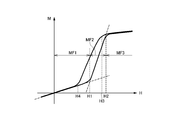
- FIG. 5 is a graph showing the magnetic characteristics of the magnetic material used for the magnetic core 11 and shows only the first quadrant (I).
- the magnetic characteristics of the magnetic core 11 will be described with reference to FIG. 5.
- the permeability is low, so that the increase in magnetization M is slight.
- the slope of the graph that is, the differential value of the magnetization M with respect to the magnetic field H is linked to the magnetic permeability.
- the magnetic permeability in the first magnetic field region MF1 is substantially the same as the magnetic permeability of the nonmagnetic material. Therefore, the first magnetic field region MF1 substantially behaves as a nonmagnetic material.
- the magnetic permeability in the region from the first magnetic field strength H1 to the second magnetic field strength H2 (second magnetic field region MF2), the magnetic permeability increases rapidly, and the value of the magnetization M increases significantly. That is, as the magnetic field is increased, the magnetic permeability rapidly increases with the first magnetic field strength H1 as a boundary.
- the magnetic permeability in the second magnetic field region MF2 is close to the magnetic permeability of the soft magnetic material, and therefore behaves softly in the second magnetic field region MF2.
- the magnetic material constituting the magnetic core 11 is not particularly limited as long as it is a magnetic material having the above-described magnetic characteristics, and examples thereof include metamagnetic materials, perminbar characteristic materials, and synthetic antiferromagnetic materials.
- the magnetic material constituting the magnetic core 11 may be a single substance of a metamagnetic material, a permember characteristic material, or a synthetic antiferromagnetic material, or a combination thereof, and a part of the magnetic core 11 is made of a ferromagnetic material. It does not matter.
- the inductance can be changed greatly depending on the magnitude of the current I flowing through the coil 12 of the current limiter 10.
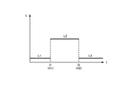
- FIG. 6 is a graph showing the relationship between the current I flowing through the coil 12 of the current limiter 10 and the inductance L.
- the current value I1 shown in FIG. 6 is a current value at which the magnetic field H applied to the magnetic core 11 becomes the first magnetic field strength H1.
- the current value I2 shown in FIG. 6 is a current value at which the magnetic field H applied to the magnetic core 11 becomes the second magnetic field strength H2.
- the value of the inductance of the current limiter 10 is L1, which is sufficiently low. This is because when the current I flowing through the coil 12 is equal to or less than the first current value I1, the magnetic core 11 is in the first magnetic field region MF1 and the magnetic permeability is sufficiently low. As a result, the current limiter 10 hardly becomes a load on the electric circuit.
- the value of the inductance of the current limiter 10 rapidly increases to L2 (> L1). This is because when the current I flowing through the coil 12 exceeds the first current value I1, the magnetic core 11 becomes the second magnetic field region MF2, and thus the magnetic permeability rapidly increases.
- the first current value I1 is an operation start point of the current limiter 10, and when the current I flowing through the coil 12 exceeds the first current value I1, the inductance of the current limiter 10 rapidly increases. As a result, when a current exceeding the first current value I1 flows in the electric circuit, the current limiter 10 spontaneously starts a current limiting operation.
- FIG. 7 is a graph showing the relationship between the voltage V applied to the coil 12 and the current I flowing through the coil 12.
- the impedance Z1 indicated by the slope of the graph is low, and the current I flowing through the coil 12 has the first current value I1. Exceeding this indicates that the impedance Z2 increases.
- the current I flowing through the coil 12 is less than or equal to the first current value I1. In some cases, the load is hardly loaded. On the other hand, when the current I flowing through the coil 12 exceeds the first current value I1, a current limiting operation can be performed by a rapid increase in inductance.
- the vertical axis is the magnetization M, but the same relationship holds even if the vertical axis is replaced with the magnetic flux density B.
- FIG. 8 is another graph showing the magnetic characteristics of the magnetic material used for the magnetic core 11.
- the horizontal axis as the first axis shows the magnetic field H, and the vertical axis as the second axis shows the magnetic flux density B. .
- the magnetic characteristic of the magnetic core 11 draws a similar characteristic curve in the first quadrant (I) of the graph. That is, the inclination is small in the first magnetic field region MF1 that is a low magnetic field, the inclination is rapidly increased in the second magnetic field region MF2 that is a medium magnetic field, and the inclination is large in the third magnetic field region MF3 that is a strong magnetic field. Becomes smaller again. Also in the graph shown in FIG. 8, the characteristic curve indicating the magnetic properties of the magnetic core 11 substantially passes through the origin, and even if it does not pass through the origin of the graph strictly, the horizontal axis or the vicinity of the origin on the vertical axis Pass through.
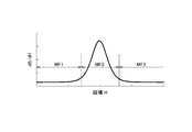
- FIG. 9 is a graph showing the differential value of the characteristic shown in FIG. 8, and FIG. 10 is a graph showing the double differential value of the characteristic shown in FIG.
- the characteristics shown in FIG. 9 correspond to the differential permeability of the magnetic material constituting the magnetic core 11.
- the differential value becomes maximum in the second magnetic field region MF2.
- the differential value remains small.
- the twice differentiated value is inverted from a positive value to a negative value in the second magnetic field region MF2.
- the twice differential value is almost zero.
- the magnetic material used for the magnetic core 11 has a characteristic that when the magnetic flux density B is differentiated twice with respect to the magnetic field H, the twice-differentiated value is inverted from a positive value to a negative value.
- FIG. 11 is a graph showing the relationship between the current I flowing through the coil 12 and the value of B / H.
- the value of B / H corresponds to the average magnetic permeability.
- examples of the magnetic material constituting the magnetic core 11 include a metamagnetic material, a Permin bar characteristic material, and a synthetic antiferromagnetic material. Which magnetic material is used may be appropriately selected according to various characteristics (mainly the value of the first magnetic field strength H1) required for the current limiter 10.
- the metamagnetic material refers to a material that undergoes a primary phase transition from a paramagnetic (PM) or anti-ferromagnetic (AFM) to ferromagnetic (FM) by a magnetic field.
- First-order phase transition by a magnetic field refers to having a point at which the change in magnetization related to the magnetic field becomes discontinuous.
- the magnetic field in which the first-order phase transition occurs in the metamagnetic material is normally a relatively large magnetic field of 1 to 10 T. Therefore, the current limiter 10 using this as the material of the magnetic core 11 includes a power system, a large-capacity capacitor circuit, and a power Applications for large currents such as transformer circuits are suitable.
- the magnetic flux density B increases rapidly if the magnetic field H is significantly increased.
- the magnetic field strength that is, the first magnetic field strength H1 that causes such a change is obtained. It is extremely strong as 10 to 100 T, and it is practically impossible to generate such a magnetic field by the coil 12 of the current limiter 10. For this reason, even if an antiferromagnetic material is used as the material of the magnetic core 11, it is practically difficult to function as a current limiting device.
- Metamagnetic materials are paramagnetic ferromagnetic transition type (PM-FM transition type) that transitions from paramagnetism to ferromagnetism by a magnetic field, and antiferromagnetic ferromagnetic transition type (AFM-FM) that transitions from antiferromagnetism to ferromagnetism. Classification).
- PM-FM transition type paramagnetic ferromagnetic transition type
- AFM-FM antiferromagnetic ferromagnetic transition type
- the primary phase transition occurs only in the vicinity of the Curie temperature, so the operating temperature of the current limiter 10 is also limited to the vicinity of the Curie temperature.
- the AFM-FM transition type the primary phase transition occurs when the temperature is equal to or lower than the Neel temperature at which the antiferromagnetic state disappears. Therefore, the current limiter 10 can be operated at a wider temperature.
- metamagnetic material examples include La (FeSi) 13 system, La (FeSi) 13 H system, MnAs system, Mn (AsSb) system, MnAl system, FeRh system, NiMnIn system, Mn 3 GaC system, Mn 3 SnC. And Mn 3 SnB-based materials.
- La (FeSi) 13 H-based, MnAs-based, Mn (AsSb) -based, and MnAl-based materials that cause a first-order phase transition near room temperature are preferable.
- a heater or a cooling device may be used to maintain the temperature range in which the primary phase transition occurs.
- the permin bar characteristic material is a material that exhibits special BH characteristics, which is confirmed by Ni45 wt% Co 25 wt% Fe residue called a permin bar.
- permin bar, Mo permin bar, super permin bar, iso palm, sen palm and the like can be mentioned.
- NiZn ferrite and CoB-based amorphous materials can also be mentioned as permin bar characteristic materials.
- the permin bar characteristic material has no hysteresis at a relatively low magnetic field and shows a linear BH characteristic with a small inclination, and shows a BH characteristic with a large inclination when exceeding a certain magnetic field (first magnetic field strength H1).
- first magnetic field strength H1 is 1/100 to 1/1000 that of the metamagnetic material. Therefore, if this material is used as the material of the magnetic core 11, a current limiter for low power is formed. It becomes possible to do.
- the permbar characteristic material if the temperature of the permbar characteristic material is below the Curie temperature at which ferromagnetism is maintained, the permeability changes in accordance with the magnetic field strength, so that it can operate in a wide range of temperatures including room temperature. Furthermore, since the permbar characteristic material has a small magnetostriction due to application of a magnetic field, it is possible to obtain high durability when used as the magnetic core 11. In addition, since the composition constituting the perminbar characteristic material is mostly a transition metal, there is also an advantage that the material cost is low compared to a metamagnetic material containing a platinum group element or a rare earth element.
- the permember characteristic material has a perminver characteristic as the material of the magnetic core 11.
- the current limiting device 10 using a material can be used as a reactor during normal operation.
- a synthetic antiferromagnetic material refers to a material that exhibits antiferromagnetic properties by antiferromagnetic coupling between a ferromagnetic phase and a ferromagnetic phase. Unlike an antiferromagnetic material, a synthetic antiferromagnetic material has a low antiferromagnetic coupling strength. Therefore, when a certain magnetic field (first magnetic field strength H1) is exceeded, a ferromagnetic magnetization arrangement is obtained.
- a specific material includes a FeCo / Ru / FeCo thin film.
- the synthetic antiferromagnetic material is used, the first magnetic field strength H1 is 1/10 to 1/100 that of the metamagnetic material. Therefore, if this is used as the material of the magnetic core 11, the current limiter for medium power is used. Can be configured.
- the current limiter 10 used in the present embodiment is obtained by winding the coil 12 around the magnetic core 11 made of the magnetic material having the above-described characteristics, and has a very simple configuration.
- the current limiting operation can be performed spontaneously and at high speed without using an active element such as a diode and a thyristor, or a direct current power source, so that it is possible to realize cost reduction and improved reliability.
- the LC resonance circuit is configured by connecting the current limiter 10 and the capacitor 50 in series, the impedance during normal operation can be extremely reduced. Become.
- FIG. 12 and 13 are operation waveform diagrams of the current limiting circuit 100 according to the present embodiment.
- FIG. 12 shows a voltage waveform applied to the load 30, and
- FIG. 13 shows a current waveform flowing through the current limiter 10. Yes.
- Both FIG. 12 and FIG. 13 show simulation results when the AC power supply 20 is a commercial power supply (50 Hz or 60 Hz, effective voltage 100 V, maximum voltage 141 V), and a short circuit accident occurs at time t1.
- the maximum value of the voltage applied to the load 30 is about 141 V, and the AC voltage supplied from the AC power supply 20 hardly decreases and the load 30 is applied to the load 30. Applied. This is because the resonance frequency of the LC resonance circuit composed of the current limiter 10 and the capacitor 50 is set in the frequency band of the AC power supply 20, and the impedance at the frequency is very low.
- the voltage applied to the load 30 becomes almost zero as shown in FIG.
- the reactance of the current limiter 10 increases instantaneously, so that an increase in current is suppressed as shown in FIG.
- FIG. 14 is a simulation result showing a current waveform flowing through the linear reactor when a normal linear reactor is used instead of the current limiter 10. As shown in FIG. 14, when a normal linear reactor is used instead of the current limiter 10, the current value increases rapidly when a short circuit accident occurs at time t ⁇ b> 1.
- the reactance of the current limiter 10 increases instantaneously when a short-circuit accident occurs, so that an increase in current is suppressed.
- the resonance frequency in the case where the magnetic field applied to the magnetic core 11 is the second magnetic field region MF2 is different from the frequency band of the AC power supply 20, the resonance operation is stopped simultaneously with the occurrence of the short-circuit accident. Can be further enhanced. Accordingly, if the current limiting circuit 100 according to the present embodiment is used, it is possible to prevent damage to system equipment and circuit elements even when a short circuit accident occurs.
- the current limiter 10 used in the above embodiment has a configuration in which the coil 12 is wound around the toroidal magnetic core 11, but the current limiter according to the present invention is not limited to this. Therefore, the shape of the magnetic core may be an E shape, U shape, or I shape other than the toroidal shape.
- the magnetic core 11 may be provided with a magnetic gap.
- the coil 12 is not limited to the coated conductor using copper (Cu) as a core material, and a superconductor may be used.
Landscapes
- Engineering & Computer Science (AREA)
- Power Engineering (AREA)
- Physics & Mathematics (AREA)
- Electromagnetism (AREA)
- Chemical & Material Sciences (AREA)
- Dispersion Chemistry (AREA)
- Emergency Protection Circuit Devices (AREA)
- Soft Magnetic Materials (AREA)
Abstract
【課題】通常動作時におけるインピーダンスが低減された限流回路を提供する。 【解決手段】磁心11と、磁心11に巻回されたコイル12と、コイル12に直列に接続されたコンデンサ50とを備える。磁心11の磁気特性は、第1軸を磁場とし第2軸を磁束密度又は磁化としたグラフの第1象限において、第1の磁場強度H1以下の第1の磁場領域MF1では、磁場に対する磁束密度又は磁化の微分値が第1の値であり、前記第1の磁場強度H1よりも強い第2の磁場領域MF2では、磁場に対する磁束密度又は磁化の微分値が第1の値よりも大きい第2の値である。コイル12とコンデンサ50は、磁心11に印加される磁場が第1の磁場領域MF1である場合に、交流電源20の周波数帯で共振する。本発明によれば、電流Iが所定値以下である場合にコイル12とコンデンサ50が共振することから、インピーダンスが小さくなる。
Description
本発明は共振型限流回路に関し、特に、リアクタンス型の限流器を含む共振型限流回路に関する。
電力系統や電気回路において短絡事故が発生すると、短絡箇所において瞬時に大電流が流れ、この電流によって系統機器や回路素子が損傷したり、場合よっては火災が発生したりすることもある。短絡事故発生時におけるこのような大電流を抑制するための機器として、従来から限流器が知られている。限流器は、近年における電力容量の増加や分散型電源の普及に伴って、今後ますます需要が高まるものと予想される。
限流器の具体的な構成は、例えば特許文献1~4に記載されている。特許文献1及び2に記載された限流器は、サイリスタとダイオードとからなるブリッジ回路にリアクトルを接続した構成を有している。また、特許文献3に記載された限流器は、直列共振回路と並列共振回路を組み合わせた構成を有している。さらに、特許文献4に記載された限流器は、直流電源を用いて可飽和直流リアクトルに磁気バイアスをかける構成を有している。
しかしながら、特許文献1~4に記載された限流器は素子数が多く、装置構成が複雑である。特に、特許文献3に記載された限流器は、ノイズを抑えるためのフィルタ回路を別途設ける必要があることから、さらに回路構成が複雑となる。また、特許文献4に記載された限流器は、磁気バイアスをかけるための直流電源が常に必要であり、直流電源が失われると限流器として機能しないという問題があった。
このように、従来の限流器は装置構成が複雑であることから、信頼性の確保が難しいばかりでなく、保守負担も大きいという問題があった。しかも、装置構成の複雑さに起因して、十分な応答速度を得ることも困難であった。
他方、限流器は、通常動作時におけるインピーダンスができるだけ小さいことが望ましい。しかしながら、限流器単体では、通常動作時におけるインピーダンスを十分に小さくすることが困難である場合があった。
したがって、本発明は、単純な装置構成を有する信頼性の高い限流回路であって、通常動作時におけるインピーダンスが低減された限流回路を提供することを目的とする。
本発明による限流回路は、交流電源から供給される電流を限流する限流回路であって、磁心及び前記磁心に巻回されたコイルを含む限流器と、前記限流器に直列に接続されたコンデンサとを備える。前記磁心の磁気特性は、第1軸を磁場とし第2軸を磁束密度又は磁化としたグラフの第1象限において、第1の磁場強度以下の第1の磁場領域では、磁場に対する磁束密度又は磁化の微分値が第1の値であり、前記第1の磁場強度よりも強い第2の磁場領域では、磁場に対する磁束密度又は磁化の微分値が前記第1の値よりも大きい第2の値である。前記コイルと前記コンデンサは、前記磁心に印加される磁場が前記第1の磁場領域である場合に、前記交流電源の周波数帯で共振するLC共振回路を構成する。
本発明によれば、コイルを流れる電流が所定値以下である場合には第1の磁場領域で動作することからリアクタンスが小さい一方、コイルを流れる電流が所定値を超えると第2の磁場領域で動作することからリアクタンスが増大する。これにより、電流が所定値以下である場合には、電力系統や電気回路に対して実質的に負荷となることなく、電流が所定値を超えた場合に限流動作を行うことができる。しかも、磁心にコイルを巻回したシンプルな装置構成であることから、低コストで信頼性の高い限流器を提供することが可能となる。さらに、磁心に印加される磁場が第1の磁場領域である場合に、LC共振回路が交流電源の周波数帯で共振することから、通常動作時におけるインピーダンスを大幅に低減することが可能となる。このような磁気特性を得るためには、磁心を構成する材料として、メタ磁性材料、パーミンバー特性材料又は合成反強磁性材料を用いればよい。
本発明において、前記磁心に印加される磁場が前記第2の磁場領域である場合における前記LC共振回路の共振周波数は、前記交流電源の周波数帯と異なることが好ましい。これによれば、異常時におけるインピーダンスがより大きくなることから、より効果的な限流動作を行うことが可能となる。
このように、本発明によれば、単純な装置構成を有する信頼性の高い限流回路であって、通常動作時におけるインピーダンスが低減された限流回路を提供することが可能となる。
以下、添付図面を参照しながら、本発明の好ましい実施形態について詳細に説明する。
図1は、本発明の実施形態による限流回路100を用いた電気回路の回路図である。
図1に示す電気回路は、交流電源20に直列に接続された限流回路100及び負荷30からなる。交流電源20は例えば商用電源であり、負荷30は交流電源20から供給される電力によって動作する各種電気機器である。本実施形態による限流回路100は、交流電源20と負荷30との間に直列に接続され、負荷30が短絡事故を起こした場合に流れる大電流を抑制する役割を果たす。図2に示すように、負荷30に対して遮断器40を直列に接続しても構わない。遮断器40を用いれば、負荷30が短絡事故を起こした場合、限流回路100によって大電流が抑制された状態で遮断器40による遮断動作を行うことができる。
図1及び図2に示すように、本実施形態による限流回路100は、リアクトル型の限流器10とコンデンサ50が直列に接続されたLC共振回路を構成する。通常動作時におけるLC共振回路の共振周波数は、交流電源20の周波数帯に設定されており、このため、通常動作時における限流回路100のインピーダンスは非常に小さい。LC共振回路の共振周波数が交流電源20の周波数と完全に一致している必要はないが、通常動作時における限流回路100のインピーダンスが十分に小さくなるよう、交流電源20の周波数近傍に設定する必要がある。これに対し、短絡事故が発生した異常時におけるLC共振回路の共振周波数は、交流電源20の周波数帯と異なっていることが好ましい。
限流器10は単純なリアクトルである。詳細については後述するが、限流器10のリアクタンスは、電流Iが所定値以下である通常動作時においては十分に小さい。しかも、上述の通り、通常動作時においてはLC共振回路が共振していることから、電気回路に与えるインピーダンスは非常に小さい。これに対し、電流Iが所定値を超えた異常時においては、限流器10のリアクタンスが大幅に上昇する。これにより、交流電源20に対して大きなインピーダンスとして働くことから、電流Iの増加が抑制される。このようなリアクタンスの変化はリアクトルの磁心に印加される磁場の変化(電磁誘導の原理)によるものであり、電流Iの変化に対して自発的に生じることから、電流値を検出するための素子などは不要である。
図3は、本実施形態において用いる限流器10の具体的構成の一例を示す図である。
図3に示す限流器10は、トロイダル型の磁心11と、磁心11に巻回されたコイル12によって構成されている。コイル12は、抵抗値の低い銅(Cu)を芯材に用いた被覆導線などを用いることが好ましい。トロイダル型の磁心11は閉磁路を構成しており、磁心11に巻回されたコイル12に電流Iが流れると、トロイダル型の磁心11を周回する磁束が発生する。しかしながら、電流Iが所定値以下である通常動作時においては磁心11の透磁率が十分に低く、このため発生するリアクタンスも小さい。そして、電流Iが所定値を超えた異常時になると磁心11の透磁率が急激に増加し、これによりリアクタンスも急激に増加する。
このような現象を発現させるべく、本実施形態においては、磁心11の材料として以下に詳述する磁性材料を用いている。
図4は、磁心11に用いられる磁性材料の磁気特性を示すグラフであり、第1軸である横軸(X軸)は磁場Hを示し、第2軸である縦軸(Y軸)は磁化Mを示している。図4において、符号Aは磁心11の磁気特性を示し、符号SMは一般的な軟磁性材料の磁気特性を示し、符号HMは一般的な硬磁性材料の磁気特性を示している。
図4において符号SMで示すように、一般的な軟磁性材料は、低磁場領域においては透磁率が高く容易に磁化される一方、磁場強度が所定値を超えると磁気飽和を起こし、それ以上はほとんど磁化されないという特性を示す。言い換えれば、磁気飽和しない磁場領域では、磁場Hに対する磁化Mの微分値が大きく、磁気飽和する磁場領域では、磁場Hに対する磁化Mの微分値が小さくなる。また、一般的な軟磁性材料は、ヒステリシスが無い、或いは、ヒステリシスが非常に小さいことから、符号SMで示す特性曲線は、グラフの原点又はその近傍を通る。したがって、符号SMで示す特性曲線は、グラフの第1象限(I)及び第3象限(III)に現れ、第2象限(II)及び第4象限(IV)には実質的に現れない。
図4において符号HMで示すように、一般的な硬磁性材料は大きなヒステリシスを有しており、磁場がゼロであっても磁化された状態が維持される。このため、符号HMで示す特性曲線は、グラフの第1象限(I)~第4象限(IV)の全てに現れる。
これらの一般的な強磁性材料に対し、本実施形態において磁心11に用いる磁性材料は、グラフの第1象限(I)及び第3象限(III)において符号Aで示すように、低磁場領域においては透磁率が低いためほとんど磁化されず、中磁場領域においては透磁率が高くなって容易に磁化され、さらに、強磁場領域になると磁気飽和を起こし、それ以上はほとんど磁化されないという特性を示す。選択する材料によっては、第1象限(I)及び第3象限(III)内において僅かにヒステリシスが存在するが、残留磁化はゼロ又は非常に小さいため、符号Aで示す特性曲線は実質的にグラフの原点を通る。符号Aで示す特性曲線が厳密にグラフの原点を通らない場合であっても、横軸又は縦軸の原点近傍を通ることになる。このことは、当該磁性材料が初期状態であるか、或いは、繰り返し磁場を印加した後の状態であるかにかかわらず、同じ磁気特性が得られることを意味する。このため、当該磁性材料を用いた限流器10は繰り返し使用することができ、且つ、限流動作が完了した後、自動復旧する。
図5は、磁心11に用いられる磁性材料の磁気特性を示すグラフであり、第1象限(I)のみを示している。
図5を用いて磁心11の磁気特性についてより具体的に説明すると、磁場Hが無い状態から磁場を高めていくと、第1の磁場強度H1までの領域(第1の磁場領域MF1)においては透磁率が低く、このため磁化Mの増加は僅かである。グラフの傾き、つまり、磁場Hに対する磁化Mの微分値は透磁率に連動する。第1の磁場領域MF1における透磁率は非磁性材料の透磁率と同程度であり、したがって、第1の磁場領域MF1においては実質的に非磁性材料として振る舞う。
一方、第1の磁場強度H1から第2の磁場強度H2までの領域(第2の磁場領域MF2)においては透磁率が急激に高くなり、磁化Mの値は大幅に増加する。つまり、磁場を高めていくと、第1の磁場強度H1を境として透磁率が急激に増加する。第2の磁場領域MF2における透磁率は軟磁性材料の透磁率に近く、したがって、第2の磁場領域MF2においては軟磁性的に振る舞う。
さらに磁場を高めることによって第2の磁場強度H2を超えると(第3の磁場領域MF3)、磁気飽和を起こし、グラフの傾き、つまり透磁率は再び低下する。
逆に、第3の磁場領域MF3から磁場を弱めていき、第3の磁場強度H3を下回ると、第4の磁場強度H4までの領域で再び透磁率が高くなる。そして、第4の磁場強度H4を下回ると透磁率が低下し、再び非磁性材料として振る舞う。このように、第1象限(I)内においてはヒステリシスを有しているものの、残留磁化はほとんど存在しないため、磁場Hを一旦ゼロ近辺に戻せば、再び上述した特性と同じ特性が得られる。
磁心11を構成する磁性材料としては、上述した磁気特性を有する磁性材料であれば特に限定されないが、一例として、メタ磁性材料、パーミンバー特性材料及び合成反強磁性材料を挙げることができる。磁心11を構成する磁性材料は、メタ磁性材料、パーミンバー特性材料又は合成反強磁性材料の単体であっても構わないし、これらの組み合わせても構わないし、磁心11の一部が強磁性材料によって構成されていても構わない。
磁心11をこのような磁性材料によって構成すれば、限流器10のコイル12に流れる電流Iの大きさによってインダクタンスを大きく変化させることが可能となる。ここで、磁心11に与えられる磁場Hは、コイル12の構造及びコイル12に流れる電流Iによって決まり、磁路長をML、コイル12の巻数をNとした場合、
H=N×I/ML
で定義される。
H=N×I/ML
で定義される。
図6は、限流器10のコイル12に流れる電流IとインダクタンスLとの関係を示すグラフである。ここで、図6に示す電流値I1は、磁心11に与えられる磁場Hが第1の磁場強度H1となる電流値である。また、図6に示す電流値I2は、磁心11に与えられる磁場Hが第2の磁場強度H2となる電流値である。
図6に示すように、コイル12に流れる電流Iが第1の電流値I1以下であれば、限流器10のインダクタンスの値はL1であり、十分に低い。これは、コイル12に流れる電流Iが第1の電流値I1以下である場合、磁心11が第1の磁場領域MF1にあり、透磁率が十分に低いからである。これにより、限流器10は電気回路に対してほとんど負荷とならない。ここで、第1の磁場領域MF1における磁心11の透磁率をμ1、磁心11の断面積をSとした場合、第1の磁場領域MF1におけるインダクタンスL1は、
L1=μ1×N2×S/ML
で定義される。
L1=μ1×N2×S/ML
で定義される。
これに対し、コイル12に流れる電流Iが第1の電流値I1を超えると、限流器10のインダクタンスの値はL2(>L1)へ急激に増加する。これは、コイル12に流れる電流Iが第1の電流値I1を超えると、磁心11が第2の磁場領域MF2となるため、透磁率が急激に増加するからである。第1の電流値I1は限流器10の動作開始点であり、コイル12に流れる電流Iが第1の電流値I1を超えると、限流器10のインダクタンスが急激に増加する。これにより、電気回路に第1の電流値I1を超える電流が流れると、限流器10は自発的に限流動作を開始することになる。ここで、第2の磁場領域MF2における磁心11の透磁率をμ2とした場合、第2の磁場領域MF2におけるインダクタンスL2は、
L2=μ2×N2×S/ML
で定義される。
L2=μ2×N2×S/ML
で定義される。
そして、コイル12に流れる電流Iが第2の電流値I2を超えると、限流器10のインダクタンスの値はL3(<L2)へ急激に減少する。これは、コイル12に流れる電流Iが第2の電流値I2を超えると、磁心11が第3の磁場領域MF3となるからである。
図7は、コイル12にかかる電圧Vとコイル12に流れる電流Iとの関係を示すグラフである。図7に示すグラフは、コイル12に流れる電流Iが第1の電流値I1以下である場合にはグラフの傾きが示すインピーダンスZ1が低く、コイル12に流れる電流Iが第1の電流値I1を超えると、インピーダンスZ2が増加することを示している。
このように、本実施形態において用いる限流器10は、磁心11が図4及び図5に示す磁気特性を有していることから、コイル12に流れる電流Iが第1の電流値I1以下である場合にはほとんど負荷とならない一方、コイル12に流れる電流Iが第1の電流値I1を超えると、インダクタンスの急激な増加によって限流動作を行うことが可能となる。尚、図4及び図5に示したグラフは縦軸が磁化Mであるが、縦軸を磁束密度Bに置き換えても、同様の関係が成り立つ。
図8は、磁心11に用いられる磁性材料の磁気特性を示す別のグラフであり、第1軸である横軸は磁場Hを示し、第2軸である縦軸は磁束密度Bを示している。
図8に示すように、縦軸を磁束密度Bに置き換えた場合であっても、磁心11の磁気特性は、グラフの第1象限(I)において同様の特性曲線を描く。つまり、低磁場である第1の磁場領域MF1においては傾きが小さく、中磁場である第2の磁場領域MF2においては傾きが急激に大きくなり、強磁場である第3の磁場領域MF3においては傾きが再び小さくなる。また、図8に示すグラフにおいても、磁心11の磁気特性を示す特性曲線は実質的に原点を通り、厳密にグラフの原点を通らない場合であっても、横軸又は縦軸の原点近傍を通る。
図9は図8に示す特性の微分値を示すグラフであり、図10は図8に示す特性の二回微分値を示すグラフである。図9に示す特性は、磁心11を構成する磁性材料の微分透磁率に相当する。
図9に示すように、図8に示す特性を一回微分すると、第2の磁場領域MF2において微分値が極大となる。第1の磁場領域MF1及び第3の磁場領域MF3では、微分値は小さい値のままである。そして、図10に示すように、図8に示す特性を二回微分すると、第2の磁場領域MF2において二回微分値が正の値から負の値に反転する。第1の磁場領域MF1及び第3の磁場領域MF3では、二回微分値はほぼゼロである。このように、磁心11に用いられる磁性材料は、磁場Hに対して磁束密度Bを二回微分すると、二回微分値が正の値から負の値に反転するという特徴を有している。
図11は、コイル12に流れる電流IとB/Hの値との関係を示すグラフである。B/Hの値は平均透磁率に相当する。
図11に示すように、コイル12に流れる電流Iが第1の電流値I1以下である場合には、B/Hの値(平均透磁率)は低く、その変化もほとんど無いことから、電気回路に与える影響は僅かである。これに対し、コイル12に流れる電流Iが第1の電流値I1を超えると、B/Hの値(平均透磁率)が急激に増加する。その後、コイル12に流れる電流Iが第2の電流値I2を超えると、B/Hの値(平均透磁率)が徐々に減少する。これは、第3の磁場領域MF3においては磁心11が磁気飽和するからである。
既に説明した通り、磁心11を構成する磁性材料としては、メタ磁性材料、パーミンバー特性材料及び合成反強磁性材料を挙げることができる。どの磁性材料を使用するかは、限流器10に求められる諸特性(主に、第1の磁場強度H1の値)に応じて適宜選択すればよい。
メタ磁性材料とは、磁場により常磁性(PM:Paramagnetic)もしくは反強磁性(AFM:Anti-Ferromagnetic)から強磁性(FM:Ferromagnetic)に一次相転移する材料を指す。磁場による一次相転移とは、磁場に関する磁化の変化が不連続になる点をもつことを指す。メタ磁性材料において一次相転移が生じる磁場は、通常1~10Tと比較的大きな磁場であるため、これを磁心11の材料として用いる限流器10としては、電力系統、大容量コンデンサ回路、電力用トランス回路といった大電流用の用途が好適である。尚、一部の反強磁性材料も、磁場Hを著しく高めれば磁束密度Bが急激に増加する特性が得られるが、そのような変化をもたらす磁場強度(つまり、第1の磁場強度H1)は10~100Tと極めて強く、限流器10のコイル12によってそのような磁場を作ることは現実的に不可能である。このため、磁心11の材料として反強磁性材料を用いても、事実上、限流器として機能させることは困難である。
メタ磁性材料は、磁場により常磁性から強磁性に転移する常磁性強磁性転移型(PM-FM転移型)と、反強磁性から強磁性に転移する反強磁性強磁性転移型(AFM-FM転移型)に分類される。PM-FM転移型は、キュリー温度の近傍でのみ一次相転移が生じることから、限流器10の動作温度もキュリー温度付近に限られる。これに対し、AFM-FM転移型は、反強磁性状態が消失するネール温度以下であれば一次相転移が生じるため、より幅広い温度で限流器10を動作させることが可能となる。
メタ磁性材料の具体例としては、La(FeSi)13系、La(FeSi)13H系、MnAs系、Mn(AsSb)系、MnAl系、FeRh系、NiMnIn系、Mn3GaC系、Mn3SnC系、Mn3SnB系材料が挙げられる。特に、室温近傍において一次相転移が生じるLa(FeSi)13H系、MnAs系、Mn(AsSb)系、MnAl系材料が好ましく、最も好ましいのは、AFM-FM転移型メタ磁性材料であるMnAl系材料である。室温近傍において一次相転移が生じない材料を使用する場合は、ヒーターもしくは冷却装置を用いて、一次相転移が生じる温度帯に維持すればよい。
次に、パーミンバー特性材料とは、パーミンバーと呼ばれるNi45wt%Co25wt%Fe残で確認された特殊なBH特性を示す材料である。具体的には、パーミンバー、Moパーミンバー、超パーミンバー、イソパーム、センパームなどが挙げられる。また、NiZnフェライトやCoB系アモルファス材料もパーミンバー特性材料として挙げられる。
パーミンバー特性材料は、比較的低い磁場ではヒステリシスがなく、且つ、傾きの小さい直線的なBH特性を示し、ある磁場(第1の磁場強度H1)を超えると、傾きの大きなBH特性を示す。パーミンバー特性材料を用いた場合、第1の磁場強度H1は、メタ磁性材料の1/100~1/1000であるため、これを磁心11の材料として用いれば、小電力用の限流器を構成することが可能となる。
また、パーミンバー特性材料は、強磁性が保たれるキュリー温度以下であれば、磁場強度に応じた透磁率の変化が生じるため、室温を含めた幅広い温度での動作が可能である。さらに、パーミンバー特性材料は、磁場印加による磁歪が小さいため、磁心11として用いた場合に高い耐久性を得ることも可能となる。しかも、パーミンバー特性材料を構成する組成は、多くが遷移金属であるため、白金族元素や希土類元素を含んだメタ磁性材料と比較して、材料コストが安いという利点もある。
尚、パーミンバー特性材料は、通常動作時(つまり、第1の磁場領域MF1)における透磁率がメタ磁性材料と比較して10~100倍以上の値を持つことから、磁心11の材料としてパーミンバー特性材料を用いた限流器10は、通常動作時にはリアクトルとして利用することも可能である。
次に、合成反強磁性材料とは、強磁性相と強磁性相が反強磁性的に結合することで、反強磁性的な特性を示す材料を指す。合成反強磁性材料は、反強磁性材料とは異なり、反強磁性結合強度が小さいため、ある磁場(第1の磁場強度H1)を超えると、強磁性的な磁化配列となる。具体的な材料としては、FeCo/Ru/FeCo薄膜が挙げられる。合成反強磁性材料を用いた場合、第1の磁場強度H1は、メタ磁性材料の1/10~1/100であるため、これを磁心11の材料として用いれば、中電力用の限流器を構成することが可能となる。
以上説明したように、本実施形態において用いる限流器10は、上述した特性を有する磁性材料からなる磁心11にコイル12を巻回したものであり、非常にシンプルな構成を有している。これにより、ダイオード及びサイリスタなどの能動素子や、直流電源などを用いることなく、自発的かつ高速に限流動作を行うことができることから、低コスト化及び信頼性の向上を実現することが可能となる。そして、本実施形態においては、このような限流器10とコンデンサ50を直列に接続することによってLC共振回路を構成していることから、通常動作時におけるインピーダンスを非常に小さくすることが可能となる。
図12及び図13は、本実施形態による限流回路100の動作波形図であり、図12は負荷30に印加される電圧波形を示し、図13は限流器10に流れる電流波形を示している。図12及び図13とも、交流電源20が商用電源(50Hz又は60Hz、実効電圧100V、最大電圧141V)であり、時刻t1において短絡事故が発生した場合のシミュレーション結果である。
図12に示すように、時刻t1以前の期間においては、負荷30に印加される電圧の最大値が約141Vであり、交流電源20から供給される交流電圧がほとんど低下することなく、負荷30に印加される。これは、限流器10とコンデンサ50からなるLC共振回路の共振周波数が交流電源20の周波数帯に設定されており、当該周波数におけるインピーダンスが非常に低いからである。そして、時刻t1において短絡事故が発生すると、図12に示すように、負荷30に印加される電圧はほぼゼロになる。しかしながら、短絡事故が発生すると限流器10のリアクタンスが瞬時に上昇することから、図13に示すように電流の増大が抑制される。
図14は、限流器10の代わりに通常の線形リアクトルを用いた場合において、線形リアクトルに流れる電流波形を示すシミュレーション結果である。図14に示すように、限流器10の代わりに通常の線形リアクトルを用いた場合、時刻t1において短絡事故が発生すると、電流値が急速に増大することが分かる。
これに対し、本実施形態による限流回路100を用いれば、短絡事故が発生すると限流器10のリアクタンスが瞬時に上昇することから、電流の増大が抑制される。しかも、磁心11に印加される磁場が第2の磁場領域MF2である場合における共振周波数が交流電源20の周波数帯と異なっていれば、短絡事故の発生と同時に共振動作も停止することから、インピーダンスをより高めることができる。これらにより、本実施形態による限流回路100を用いれば、短絡事故が発生した場合であっても、系統機器や回路素子の損傷を防止することが可能となる。
以上、本発明の好ましい実施形態について説明したが、本発明は、上記の実施形態に限定されることなく、本発明の主旨を逸脱しない範囲で種々の変更が可能であり、それらも本発明の範囲内に包含されるものであることはいうまでもない。
例えば、上記実施形態において用いた限流器10は、トロイダル型の磁心11にコイル12を巻回した構成を有しているが、本発明による限流器がこれに限定されるものではない。したがって、磁心の形状としてはトロイダル型以外のE型、U型、I型形状であっても構わない。また、磁心11には磁気ギャップが設けられていても構わない。コイル12についても、銅(Cu)を芯材に用いた被覆導線に限定されず、超伝導体を用いても構わない。
10 限流器
11 磁心
12 コイル
20 交流電源
30 負荷
40 遮断器
50 コンデンサ
100 限流回路
11 磁心
12 コイル
20 交流電源
30 負荷
40 遮断器
50 コンデンサ
100 限流回路
Claims (3)
- 交流電源から供給される電流を限流する限流回路であって、
磁心及び前記磁心に巻回されたコイルを含む限流器と、
前記限流器に直列に接続されたコンデンサと、を備え、
前記磁心の磁気特性は、第1軸を磁場とし第2軸を磁束密度又は磁化としたグラフの第1象限において、第1の磁場強度以下の第1の磁場領域では、磁場に対する磁束密度又は磁化の微分値が第1の値であり、前記第1の磁場強度よりも強い第2の磁場領域では、磁場に対する磁束密度又は磁化の微分値が前記第1の値よりも大きい第2の値であり、
前記コイルと前記コンデンサは、前記磁心に印加される磁場が前記第1の磁場領域である場合に、前記交流電源の周波数帯で共振するLC共振回路を構成することを特徴とする共振型限流回路。 - 前記磁心に印加される磁場が前記第2の磁場領域である場合における前記LC共振回路の共振周波数は、前記交流電源の周波数帯と異なることを特徴とする請求項1に記載の共振型限流回路。
- 前記磁心は、メタ磁性材料、パーミンバー特性材料又は合成反強磁性材料を含むことを特徴とする請求項1又は2に記載の共振型限流回路。
Applications Claiming Priority (2)
| Application Number | Priority Date | Filing Date | Title |
|---|---|---|---|
| JP2017-000363 | 2017-01-05 | ||
| JP2017000363A JP6825369B2 (ja) | 2017-01-05 | 2017-01-05 | 共振型限流回路 |
Publications (1)
| Publication Number | Publication Date |
|---|---|
| WO2018128151A1 true WO2018128151A1 (ja) | 2018-07-12 |
Family
ID=62790902
Family Applications (1)
| Application Number | Title | Priority Date | Filing Date |
|---|---|---|---|
| PCT/JP2017/046984 Ceased WO2018128151A1 (ja) | 2017-01-05 | 2017-12-27 | 共振型限流回路 |
Country Status (2)
| Country | Link |
|---|---|
| JP (1) | JP6825369B2 (ja) |
| WO (1) | WO2018128151A1 (ja) |
Citations (2)
| Publication number | Priority date | Publication date | Assignee | Title |
|---|---|---|---|---|
| JPS5866833U (ja) * | 1981-10-27 | 1983-05-07 | 日新電機株式会社 | 限流装置 |
| JPS5866832U (ja) * | 1981-10-27 | 1983-05-07 | 日新電機株式会社 | 限流装置 |
-
2017
- 2017-01-05 JP JP2017000363A patent/JP6825369B2/ja active Active
- 2017-12-27 WO PCT/JP2017/046984 patent/WO2018128151A1/ja not_active Ceased
Patent Citations (2)
| Publication number | Priority date | Publication date | Assignee | Title |
|---|---|---|---|---|
| JPS5866833U (ja) * | 1981-10-27 | 1983-05-07 | 日新電機株式会社 | 限流装置 |
| JPS5866832U (ja) * | 1981-10-27 | 1983-05-07 | 日新電機株式会社 | 限流装置 |
Also Published As
| Publication number | Publication date |
|---|---|
| JP6825369B2 (ja) | 2021-02-03 |
| JP2018110493A (ja) | 2018-07-12 |
Similar Documents
| Publication | Publication Date | Title |
|---|---|---|
| Hasegawa | Applications of amorphous magnetic alloys | |
| Makino et al. | Applications of nanocrystalline soft magnetic Fe-MB (M= Zr, Nb) alloys" NANOPERM (R)" | |
| Petzold | Advantages of softmagnetic nanocrystalline materials for modern electronic applications | |
| Jiles | Recent advances and future directions in magnetic materials | |
| CN107919434B (zh) | 频率可变磁电阻效应元件以及使用该元件的振荡器、检波器及滤波器 | |
| CN105074843B (zh) | 使用了Fe基纳米晶体软磁性合金的环状磁芯、以及使用其的磁性部件 | |
| CN107464649B (zh) | 一种具有线性磁滞回线的磁芯 | |
| KR20070074059A (ko) | 자기 코어 및 이를 포함하는 인덕터, 변압기 | |
| JP2563097B2 (ja) | 微結晶鉄ベース合金から成る漏電遮断器用磁心材料 | |
| Naitoh et al. | Applications of nanocrystalline soft magnetic Fe-MB (M= Zr, Nb) alloys | |
| JPH0614453A (ja) | 超電導応用限流装置 | |
| Kumar et al. | Ferrite nanoparticles for telecommunication application | |
| US2498475A (en) | Saturable magnetic core | |
| Hoshino et al. | Design of 6.6 kV, 100 A saturated DC reactor type superconducting fault current limiter | |
| Schaefer et al. | Magnetic losses in ferrites and nanocrystalline ribbons for power applications | |
| JP6760085B2 (ja) | 限流器及びこれを備える共振型限流回路 | |
| JP6825369B2 (ja) | 共振型限流回路 | |
| JP7127545B2 (ja) | 電磁アクチュエータ | |
| GB2598365A (en) | Current controlling element based on saturation of a magnetic circuit | |
| Pfeifer et al. | New soft magnetic alloys for applications in modern electrotechnics and electronics | |
| CN104769690A (zh) | 磁热限流装置 | |
| JP2019047690A (ja) | 直流遮断器 | |
| US20120256614A1 (en) | Technique for limiting fault current transmission | |
| Slavkova | Specific Applications of Nanocrystalline and Amorphous Soft Magnetic Materials with Different Hysteresis Loops | |
| Young et al. | A three‐material passive dI/dt limiter |
Legal Events
| Date | Code | Title | Description |
|---|---|---|---|
| 121 | Ep: the epo has been informed by wipo that ep was designated in this application |
Ref document number: 17890574 Country of ref document: EP Kind code of ref document: A1 |
|
| NENP | Non-entry into the national phase |
Ref country code: DE |
|
| 122 | Ep: pct application non-entry in european phase |
Ref document number: 17890574 Country of ref document: EP Kind code of ref document: A1 |