WO2018124263A1 - Bonding material, and bonding method using same - Google Patents
Bonding material, and bonding method using same Download PDFInfo
- Publication number
- WO2018124263A1 WO2018124263A1 PCT/JP2017/047171 JP2017047171W WO2018124263A1 WO 2018124263 A1 WO2018124263 A1 WO 2018124263A1 JP 2017047171 W JP2017047171 W JP 2017047171W WO 2018124263 A1 WO2018124263 A1 WO 2018124263A1
- Authority
- WO
- WIPO (PCT)
- Prior art keywords
- bonding material
- bonding
- chain
- fine particles
- silver fine
- Prior art date
Links
Images


Classifications
-
- H—ELECTRICITY
- H01—ELECTRIC ELEMENTS
- H01L—SEMICONDUCTOR DEVICES NOT COVERED BY CLASS H10
- H01L24/00—Arrangements for connecting or disconnecting semiconductor or solid-state bodies; Methods or apparatus related thereto
- H01L24/01—Means for bonding being attached to, or being formed on, the surface to be connected, e.g. chip-to-package, die-attach, "first-level" interconnects; Manufacturing methods related thereto
- H01L24/26—Layer connectors, e.g. plate connectors, solder or adhesive layers; Manufacturing methods related thereto
- H01L24/28—Structure, shape, material or disposition of the layer connectors prior to the connecting process
- H01L24/29—Structure, shape, material or disposition of the layer connectors prior to the connecting process of an individual layer connector
-
- B—PERFORMING OPERATIONS; TRANSPORTING
- B22—CASTING; POWDER METALLURGY
- B22F—WORKING METALLIC POWDER; MANUFACTURE OF ARTICLES FROM METALLIC POWDER; MAKING METALLIC POWDER; APPARATUS OR DEVICES SPECIALLY ADAPTED FOR METALLIC POWDER
- B22F1/00—Metallic powder; Treatment of metallic powder, e.g. to facilitate working or to improve properties
- B22F1/05—Metallic powder characterised by the size or surface area of the particles
- B22F1/054—Nanosized particles
- B22F1/056—Submicron particles having a size above 100 nm up to 300 nm
-
- B—PERFORMING OPERATIONS; TRANSPORTING
- B22—CASTING; POWDER METALLURGY
- B22F—WORKING METALLIC POWDER; MANUFACTURE OF ARTICLES FROM METALLIC POWDER; MAKING METALLIC POWDER; APPARATUS OR DEVICES SPECIALLY ADAPTED FOR METALLIC POWDER
- B22F1/00—Metallic powder; Treatment of metallic powder, e.g. to facilitate working or to improve properties
- B22F1/10—Metallic powder containing lubricating or binding agents; Metallic powder containing organic material
- B22F1/102—Metallic powder coated with organic material
-
- B—PERFORMING OPERATIONS; TRANSPORTING
- B22—CASTING; POWDER METALLURGY
- B22F—WORKING METALLIC POWDER; MANUFACTURE OF ARTICLES FROM METALLIC POWDER; MAKING METALLIC POWDER; APPARATUS OR DEVICES SPECIALLY ADAPTED FOR METALLIC POWDER
- B22F1/00—Metallic powder; Treatment of metallic powder, e.g. to facilitate working or to improve properties
- B22F1/10—Metallic powder containing lubricating or binding agents; Metallic powder containing organic material
- B22F1/107—Metallic powder containing lubricating or binding agents; Metallic powder containing organic material containing organic material comprising solvents, e.g. for slip casting
-
- B—PERFORMING OPERATIONS; TRANSPORTING
- B22—CASTING; POWDER METALLURGY
- B22F—WORKING METALLIC POWDER; MANUFACTURE OF ARTICLES FROM METALLIC POWDER; MAKING METALLIC POWDER; APPARATUS OR DEVICES SPECIALLY ADAPTED FOR METALLIC POWDER
- B22F7/00—Manufacture of composite layers, workpieces, or articles, comprising metallic powder, by sintering the powder, with or without compacting wherein at least one part is obtained by sintering or compression
- B22F7/06—Manufacture of composite layers, workpieces, or articles, comprising metallic powder, by sintering the powder, with or without compacting wherein at least one part is obtained by sintering or compression of composite workpieces or articles from parts, e.g. to form tipped tools
- B22F7/062—Manufacture of composite layers, workpieces, or articles, comprising metallic powder, by sintering the powder, with or without compacting wherein at least one part is obtained by sintering or compression of composite workpieces or articles from parts, e.g. to form tipped tools involving the connection or repairing of preformed parts
- B22F7/064—Manufacture of composite layers, workpieces, or articles, comprising metallic powder, by sintering the powder, with or without compacting wherein at least one part is obtained by sintering or compression of composite workpieces or articles from parts, e.g. to form tipped tools involving the connection or repairing of preformed parts using an intermediate powder layer
-
- B—PERFORMING OPERATIONS; TRANSPORTING
- B23—MACHINE TOOLS; METAL-WORKING NOT OTHERWISE PROVIDED FOR
- B23K—SOLDERING OR UNSOLDERING; WELDING; CLADDING OR PLATING BY SOLDERING OR WELDING; CUTTING BY APPLYING HEAT LOCALLY, e.g. FLAME CUTTING; WORKING BY LASER BEAM
- B23K35/00—Rods, electrodes, materials, or media, for use in soldering, welding, or cutting
- B23K35/02—Rods, electrodes, materials, or media, for use in soldering, welding, or cutting characterised by mechanical features, e.g. shape
- B23K35/0222—Rods, electrodes, materials, or media, for use in soldering, welding, or cutting characterised by mechanical features, e.g. shape for use in soldering, brazing
- B23K35/0244—Powders, particles or spheres; Preforms made therefrom
-
- B—PERFORMING OPERATIONS; TRANSPORTING
- B23—MACHINE TOOLS; METAL-WORKING NOT OTHERWISE PROVIDED FOR
- B23K—SOLDERING OR UNSOLDERING; WELDING; CLADDING OR PLATING BY SOLDERING OR WELDING; CUTTING BY APPLYING HEAT LOCALLY, e.g. FLAME CUTTING; WORKING BY LASER BEAM
- B23K35/00—Rods, electrodes, materials, or media, for use in soldering, welding, or cutting
- B23K35/22—Rods, electrodes, materials, or media, for use in soldering, welding, or cutting characterised by the composition or nature of the material
- B23K35/24—Selection of soldering or welding materials proper
- B23K35/26—Selection of soldering or welding materials proper with the principal constituent melting at less than 400 degrees C
-
- B—PERFORMING OPERATIONS; TRANSPORTING
- B23—MACHINE TOOLS; METAL-WORKING NOT OTHERWISE PROVIDED FOR
- B23K—SOLDERING OR UNSOLDERING; WELDING; CLADDING OR PLATING BY SOLDERING OR WELDING; CUTTING BY APPLYING HEAT LOCALLY, e.g. FLAME CUTTING; WORKING BY LASER BEAM
- B23K35/00—Rods, electrodes, materials, or media, for use in soldering, welding, or cutting
- B23K35/22—Rods, electrodes, materials, or media, for use in soldering, welding, or cutting characterised by the composition or nature of the material
- B23K35/24—Selection of soldering or welding materials proper
- B23K35/30—Selection of soldering or welding materials proper with the principal constituent melting at less than 1550 degrees C
- B23K35/3006—Ag as the principal constituent
-
- B—PERFORMING OPERATIONS; TRANSPORTING
- B23—MACHINE TOOLS; METAL-WORKING NOT OTHERWISE PROVIDED FOR
- B23K—SOLDERING OR UNSOLDERING; WELDING; CLADDING OR PLATING BY SOLDERING OR WELDING; CUTTING BY APPLYING HEAT LOCALLY, e.g. FLAME CUTTING; WORKING BY LASER BEAM
- B23K35/00—Rods, electrodes, materials, or media, for use in soldering, welding, or cutting
- B23K35/22—Rods, electrodes, materials, or media, for use in soldering, welding, or cutting characterised by the composition or nature of the material
- B23K35/36—Selection of non-metallic compositions, e.g. coatings, fluxes; Selection of soldering or welding materials, conjoint with selection of non-metallic compositions, both selections being of interest
- B23K35/365—Selection of non-metallic compositions of coating materials either alone or conjoint with selection of soldering or welding materials
-
- H—ELECTRICITY
- H01—ELECTRIC ELEMENTS
- H01B—CABLES; CONDUCTORS; INSULATORS; SELECTION OF MATERIALS FOR THEIR CONDUCTIVE, INSULATING OR DIELECTRIC PROPERTIES
- H01B1/00—Conductors or conductive bodies characterised by the conductive materials; Selection of materials as conductors
-
- H—ELECTRICITY
- H01—ELECTRIC ELEMENTS
- H01B—CABLES; CONDUCTORS; INSULATORS; SELECTION OF MATERIALS FOR THEIR CONDUCTIVE, INSULATING OR DIELECTRIC PROPERTIES
- H01B1/00—Conductors or conductive bodies characterised by the conductive materials; Selection of materials as conductors
- H01B1/20—Conductive material dispersed in non-conductive organic material
- H01B1/22—Conductive material dispersed in non-conductive organic material the conductive material comprising metals or alloys
-
- H—ELECTRICITY
- H01—ELECTRIC ELEMENTS
- H01L—SEMICONDUCTOR DEVICES NOT COVERED BY CLASS H10
- H01L24/00—Arrangements for connecting or disconnecting semiconductor or solid-state bodies; Methods or apparatus related thereto
- H01L24/80—Methods for connecting semiconductor or other solid state bodies using means for bonding being attached to, or being formed on, the surface to be connected
- H01L24/83—Methods for connecting semiconductor or other solid state bodies using means for bonding being attached to, or being formed on, the surface to be connected using a layer connector
-
- B—PERFORMING OPERATIONS; TRANSPORTING
- B22—CASTING; POWDER METALLURGY
- B22F—WORKING METALLIC POWDER; MANUFACTURE OF ARTICLES FROM METALLIC POWDER; MAKING METALLIC POWDER; APPARATUS OR DEVICES SPECIALLY ADAPTED FOR METALLIC POWDER
- B22F2301/00—Metallic composition of the powder or its coating
- B22F2301/25—Noble metals, i.e. Ag Au, Ir, Os, Pd, Pt, Rh, Ru
- B22F2301/255—Silver or gold
-
- B—PERFORMING OPERATIONS; TRANSPORTING
- B22—CASTING; POWDER METALLURGY
- B22F—WORKING METALLIC POWDER; MANUFACTURE OF ARTICLES FROM METALLIC POWDER; MAKING METALLIC POWDER; APPARATUS OR DEVICES SPECIALLY ADAPTED FOR METALLIC POWDER
- B22F2304/00—Physical aspects of the powder
- B22F2304/05—Submicron size particles
- B22F2304/056—Particle size above 100 nm up to 300 nm
-
- B—PERFORMING OPERATIONS; TRANSPORTING
- B22—CASTING; POWDER METALLURGY
- B22F—WORKING METALLIC POWDER; MANUFACTURE OF ARTICLES FROM METALLIC POWDER; MAKING METALLIC POWDER; APPARATUS OR DEVICES SPECIALLY ADAPTED FOR METALLIC POWDER
- B22F9/00—Making metallic powder or suspensions thereof
- B22F9/16—Making metallic powder or suspensions thereof using chemical processes
- B22F9/18—Making metallic powder or suspensions thereof using chemical processes with reduction of metal compounds
- B22F9/24—Making metallic powder or suspensions thereof using chemical processes with reduction of metal compounds starting from liquid metal compounds, e.g. solutions
-
- H—ELECTRICITY
- H01—ELECTRIC ELEMENTS
- H01L—SEMICONDUCTOR DEVICES NOT COVERED BY CLASS H10
- H01L2224/00—Indexing scheme for arrangements for connecting or disconnecting semiconductor or solid-state bodies and methods related thereto as covered by H01L24/00
- H01L2224/01—Means for bonding being attached to, or being formed on, the surface to be connected, e.g. chip-to-package, die-attach, "first-level" interconnects; Manufacturing methods related thereto
- H01L2224/26—Layer connectors, e.g. plate connectors, solder or adhesive layers; Manufacturing methods related thereto
- H01L2224/28—Structure, shape, material or disposition of the layer connectors prior to the connecting process
- H01L2224/29—Structure, shape, material or disposition of the layer connectors prior to the connecting process of an individual layer connector
- H01L2224/29001—Core members of the layer connector
- H01L2224/29099—Material
- H01L2224/29198—Material with a principal constituent of the material being a combination of two or more materials in the form of a matrix with a filler, i.e. being a hybrid material, e.g. segmented structures, foams
- H01L2224/29298—Fillers
- H01L2224/29299—Base material
- H01L2224/293—Base material with a principal constituent of the material being a metal or a metalloid, e.g. boron [B], silicon [Si], germanium [Ge], arsenic [As], antimony [Sb], tellurium [Te] and polonium [Po], and alloys thereof
- H01L2224/29338—Base material with a principal constituent of the material being a metal or a metalloid, e.g. boron [B], silicon [Si], germanium [Ge], arsenic [As], antimony [Sb], tellurium [Te] and polonium [Po], and alloys thereof the principal constituent melting at a temperature of greater than or equal to 950°C and less than 1550°C
- H01L2224/29339—Silver [Ag] as principal constituent
-
- H—ELECTRICITY
- H01—ELECTRIC ELEMENTS
- H01L—SEMICONDUCTOR DEVICES NOT COVERED BY CLASS H10
- H01L2224/00—Indexing scheme for arrangements for connecting or disconnecting semiconductor or solid-state bodies and methods related thereto as covered by H01L24/00
- H01L2224/80—Methods for connecting semiconductor or other solid state bodies using means for bonding being attached to, or being formed on, the surface to be connected
- H01L2224/83—Methods for connecting semiconductor or other solid state bodies using means for bonding being attached to, or being formed on, the surface to be connected using a layer connector
- H01L2224/832—Applying energy for connecting
- H01L2224/83201—Compression bonding
- H01L2224/83203—Thermocompression bonding, e.g. diffusion bonding, pressure joining, thermocompression welding or solid-state welding
-
- H—ELECTRICITY
- H01—ELECTRIC ELEMENTS
- H01L—SEMICONDUCTOR DEVICES NOT COVERED BY CLASS H10
- H01L2224/00—Indexing scheme for arrangements for connecting or disconnecting semiconductor or solid-state bodies and methods related thereto as covered by H01L24/00
- H01L2224/80—Methods for connecting semiconductor or other solid state bodies using means for bonding being attached to, or being formed on, the surface to be connected
- H01L2224/83—Methods for connecting semiconductor or other solid state bodies using means for bonding being attached to, or being formed on, the surface to be connected using a layer connector
- H01L2224/838—Bonding techniques
- H01L2224/8384—Sintering
-
- H—ELECTRICITY
- H01—ELECTRIC ELEMENTS
- H01L—SEMICONDUCTOR DEVICES NOT COVERED BY CLASS H10
- H01L2924/00—Indexing scheme for arrangements or methods for connecting or disconnecting semiconductor or solid-state bodies as covered by H01L24/00
- H01L2924/10—Details of semiconductor or other solid state devices to be connected
- H01L2924/102—Material of the semiconductor or solid state bodies
- H01L2924/1025—Semiconducting materials
- H01L2924/10251—Elemental semiconductors, i.e. Group IV
- H01L2924/10253—Silicon [Si]
Definitions
- the present invention relates to a bonding material and a bonding method using the same, and more particularly to a bonding material containing silver fine particles and a bonding method using the same.
- Metals are known to exhibit size-specific physical properties when the particle size is reduced.
- nano-order particles may exhibit different properties from the bulk material. Utilizing such properties, bonding materials between different substances using nano metal particles have been proposed.
- Patent Document 1 discloses that an average primary particle diameter (D50) measured by a microtrack particle size distribution measuring device is obtained in order to ensure bonding strength even with a simple configuration as much as possible and to reduce unevenness in bonding strength.
- Diameter 0.5 to 3.0 ⁇ m of silver fine particles, an average primary particle diameter of 1 to 200 nm, silver fine particles coated with a fatty acid having 6 carbon atoms, and a bonding material containing a dispersion medium for dispersing them Is disclosed.
- Patent Document 2 even if the silver content is increased, it can be uniformly applied to the joint surface, and by forming a dense joint layer, the number of carbon atoms is to be able to withstand repeated heat shocks.
- a bonding material comprising silver fine particles of 3 to 3.0 ⁇ m and a dispersant having a phosphate group is disclosed.
- the present inventors considered that it is appropriate to evaluate whether voids or cracks exist in the bonding layer.
- the fact that there are few voids and cracks in the bonding layer and the absence of the bonding layer is expressed as good bonding properties.
- the present inventors it has been found that the above-mentioned fine nano-sized silver fine particles are effective in improving the bonding property but deteriorate the dispensing property.
- an object of the present invention is to provide a bonding material having a good trade-off relationship and good dispensing properties and bonding properties, and a bonding method using the same.
- the present inventors have realized a balance between dispenseability and bondability by adding a substance having a function of appropriately maintaining the interval between silver fine particles to the bonding material. As a result, the present invention has been completed.
- the first aspect of the present invention is: Silver fine particles having an average primary particle diameter of 130 nm or less; A crosslinkable interparticle distance retention agent that crosslinks between the silver fine particles and maintains the spacing between the silver fine particles; It is a joining material containing.
- the crosslinkable interparticle distance holding agent is a compound ⁇ represented by the following formula (I).
- R is a divalent to tetravalent organic group
- a and B are a hydroxyl group, an amino group, a carboxyl group or a thiol group, and when two A are present, they may be the same or different from each other, and when two B are present, May be the same or different from each other
- the longest straight chain portion constituting R the longest of the portions between the atom 1 bonded to A and the atom 2 bonded to B is defined as the first main chain.
- the number of chain constituent atoms is 10 to 180.
- At least one of A and B in the formula (I) is a hydroxyl group, an amino group or a thiol group
- the longest straight chain part constituting R in the formula (I) has a side chain, and the number of chain constituent atoms of the longest straight chain part in the side chain is 1 of the number of chain constituent atoms of the first main chain. / 3 or less.
- the longest straight chain portion constituting R in the formula (I) has a side chain, the side chain is a hydrocarbon group having 1 to 12 carbon atoms, and A and B are bonded to the side chain. Also good.
- R a is the side chain having the longest linear portion constituting the R
- X is a halogen.
- the compound ⁇ is any one of the following formulas (II) to (IV).
- v and y are each independently an integer of 1 to 2
- w is an integer of 0 to 10
- x is an integer of 14 to 40.
- a plurality of ks each independently represents an integer of 3 to 10
- each of a plurality of ls independently represents an integer of 6 to 16
- m is an integer of 2 to 8.
- n and s are each independently an integer of 3 to 10
- p and r are each independently an integer of 6 to 18, and q is an integer of 2 to 10.
- It further contains silver particles having an average primary particle size of 0.3 to 10 ⁇ m.
- the silver fine particles are coated with an organic compound.
- a bonding layer is formed from the bonding material by heating the bonding material according to any one of the first to tenth aspects interposed between objects to be bonded. This is a joining method for joining the objects to be joined together.
- FIG. 2 is a photograph showing the result of observing a joined body obtained using a joining material by C-SAM, where (a) shows the results according to Example 1, and (b) shows the results according to Comparative Example 1.
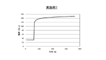
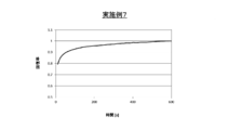
- FIG. It is a plot which shows the result of a time-dependent change of the viscosity at the time of changing shear strength (shear rate: 1 / s) with respect to the joining material which concerns on Example 1, a horizontal axis is time (s), and a vertical axis
- a horizontal axis shows time (s) and a vertical axis
- shaft shows a recovery rate.
- a horizontal axis is time (s)
- a vertical axis is.
- Viscosity (Pa ⁇ s) is shown.
- a horizontal axis shows time (s) and a vertical axis
- shaft shows a recovery rate.
- ⁇ refers to a value that is greater than or equal to a predetermined value and less than or equal to a predetermined value.
- Bonding material 1-1 Silver fine particles 1-2. Silver particles 1-3. Cross-linking interparticle distance retaining agent 1-4. Solvent 1-5. Dispersant 1-6. Others 1-7. 1. Manufacturing method of bonding material Joining method using joining material
- Bonding material Each element constituting the bonding material (a silver paste containing silver fine particles) in the present embodiment will be described.
- Silver fine particles The silver fine particles used in the present embodiment are not particularly limited as long as the average primary particle diameter is 130 nm or less.
- a method for producing silver fine particles a known method may be used, or known silver fine particles having an average primary particle diameter of 130 nm or less may be used.
- Silver fine particles having an average primary particle size of 130 nm or less have good bonding properties, and silver fine particles having an average primary particle size of 1 to 40 nm are particularly excellent in bonding properties.
- the average primary particle diameter of the silver fine particles is more preferably 5 to 30 nm, and further preferably 10 to 20 nm.
- silver fine particles having an average primary particle size of 41 nm or more are not as good as silver fine particles of 40 nm or less, but have good bonding properties, and at the same time, the viscosity of the bonding material (compared with the case where silver fine particles of 40 nm or less are added). ) Can be reduced to facilitate printing of the bonding material.
- the average primary particle size of the silver fine particles is preferably 50 to 115 nm, and more preferably 55 to 100 nm.
- silver fine particles are used in combination with silver fine particles having an average primary particle diameter of 1 to 40 nm and silver fine particles having an average primary particle diameter of 41 to 130 nm. May be.
- the average primary particle diameter of the metal particles is determined from a transmission electron micrograph (TEM image) or a scanning electron micrograph (SEM image) of the metal particles.
- the average primary particle size More specifically, for example, metal particles can be obtained using a transmission electron microscope (TEM) (JEM-1011 manufactured by JEOL Ltd.) or a scanning electron microscope (SEM) (S-4700 manufactured by Hitachi High-Technologies Corporation). Can be calculated from the primary particle diameter of 100 or more arbitrary metal particles (the diameter of a circle having the same area as the metal particles) on an image (SEM image or TEM image) observed at a predetermined magnification.
- the average primary particle diameter of the metal particles can be calculated by, for example, image analysis software (A image-kun (registered trademark) manufactured by Asahi Kasei Engineering Co., Ltd.).
- the silver fine particles used in the present invention are preferably coated with an organic compound because the average primary particle diameter is as small as 130 nm or less and easily aggregates.
- the organic compound has 8 or less carbon atoms, preferably 2 to 6 carbon atoms so as not to be sufficiently separated from the silver fine particles by firing at a low temperature (for example, 170 to 400 ° C.) to prevent sintering of the silver fine particles.
- saturated fatty acids, unsaturated fatty acids and amines are preferred. Examples of such fatty acids and amines include hexanoic acid, sorbic acid, hexylamine and octylamine.
- the content of the silver fine particles described above in the bonding material of the present embodiment is preferably 4 to 97% by mass, and more preferably 4 to 85% by mass from the viewpoint of developing an appropriate bonding force. .
- Silver particles having an average primary particle size of 0.3 ⁇ m to 10 ⁇ m may be added to the bonding material of the present embodiment.
- the average primary particle diameter of the silver particles is more preferably 0.3 to 5 ⁇ m, still more preferably 0.3 to 3 ⁇ m.
- this silver particle may be coat
- the content of the silver particles in the bonding material of the present embodiment is preferably 20 to 80% by mass from the viewpoint of ensuring printability without reducing the compounding amount of the silver fine particles and impairing the bonding properties. .
- the total content of the silver fine particles and the silver particles in the bonding material of this embodiment when using silver particles is preferably 85 to 97% by mass, and 87 to 95% by mass. More preferably.
- crosslinkable interparticle distance retainer The bonding material in the present embodiment contains a crosslinkable interparticle distance retainer that crosslinks between the silver fine particles and maintains the distance between the silver fine particles.
- a crosslinkable interparticle distance retainer that crosslinks between the silver fine particles and maintains the distance between the silver fine particles.
- the cross-linking interparticle distance maintaining agent improves the dispensing property of the bonding material.
- the cross-link type interparticle distance holding agent is volatilized by heating during firing (for example, heated at 170 to 400 ° C.), or at least the molecular motion becomes active and is easily detached from the silver fine particles. Therefore, good bonding properties can be realized.
- metal particles other than silver fine particles are present in the bonding material, such a metal particle, or the metal particles and silver fine particles can be cross-linked by a crosslinkable interparticle distance holding agent.
- any crosslinkable interparticle distance retaining agent can be used without particular limitation as long as it is capable of crosslinking (connecting) the silver fine particles and exhibiting the above functions.
- this cross-linking for example, any silver fine particles may be connected to each other through a cross-linking inter-particle distance holding agent by being connected to silver itself.
- the crosslinkable interparticle distance holding agent has a plurality of functional groups (for example, a hydroxyl group, an amino group, a thiol group, and a carboxyl group) having an affinity for the silver fine particles in order to crosslink the silver fine particles.
- the cross-link type interparticle distance retention agent retains the spacing between the silver particles, but if the spacing is long, the silver particles are spaced from each other, causing voids during sintering and causing cracks and the like. Therefore, as the cross-linking interparticle distance holding agent, those having a molecular length and a molecular structure that hold silver fine particles at appropriate intervals from such a point are preferable. By using such a cross-linking interparticle distance holding agent, it is possible to achieve both good dispensing properties and bonding properties in a bonding material containing silver fine particles.
- the crosslinkable interparticle distance holding agent is, for example, a compound ⁇ represented by the following formula (I).
- R is a divalent to tetravalent organic group
- a and B are a hydroxyl group, an amino group, a carboxyl group, or a thiol group, and in the longest linear portion constituting R ,
- the longest of the portions between the atom 1 bonded to A and the atom 2 bonded to B is the first main chain
- the number of chain constituent atoms of the first main chain is 10 to 180 .
- two A may mutually be same or different.
- B may be bonded to an arbitrary position of the longest straight chain portion of R, and may not be bonded to the end of the straight chain portion.
- R may have a side chain.
- a and B may be bonded to this side chain.
- the definition of the first main chain described above means that when there are a plurality of A and B, the first main chain is seen on the most molecular end side.
- the number of atoms constituting the first main chain is 10 to 180, A and B are separated to some extent, and the silver fine particles as the above-mentioned cross-linking interparticle distance holding agent are arranged at appropriate intervals.
- maintain suitably is demonstrated. From the viewpoint of this function, the number of atoms constituting the first main chain is preferably 20 to 120.
- the side chain in the first main chain is a chain constituent atom in accordance with the definition of “the longest portion between the atom 1 bonded to A and the atom 2 bonded to B”. Don't count in numbers.
- the chain constituent atom is a divalent or higher valent atom and is an atom bonded to two or more divalent or higher valent atoms.
- the chain constituent atoms include divalent atoms constituting A and B (for example, O, N, C, S). The larger the number of chain constituent atoms, the longer the chain.
- At least one of A and B in the formula (I) is a hydroxyl group, an amino group or a thiol group, and the longest straight chain portion constituting R in the formula (I) has a side chain.
- the number of chain constituent atoms of the longest straight chain portion in the side chain is preferably 1/3 or less of the number of chain constituent atoms of the first main chain. In this case, in the recovery of the viscosity of the bonding material shown in the examples described later, the recovery starts, and the original viscosity of the bonding material can be recovered in a short time.
- the number of chain constituent atoms of the longest straight chain portion in the side chain at this time is preferably 1/100 or more of the number of chain constituent atoms of the first main chain.
- the chain constituent atom of the longest straight chain portion in the side chain is the same as the chain constituent atom in the first main chain, and includes a divalent or higher-valent atom bonded to H at the end of the side chain.
- a and B are hydroxyl groups, amino groups or thiol groups, from the viewpoint of early recovery of the viscosity of the bonding material and the viewpoint of bonding properties, from these viewpoints.
- all of A and B are hydroxyl groups.
- examples of the side chain include hydrocarbon groups having 1 to 12 carbon atoms (preferably 2 to 8 carbon atoms). It is done.
- this hydrocarbon group may be saturated or unsaturated, and may have a branch.
- the difference in the number of atoms constituting the second main chain and the first main chain is The number of atoms constituting the chain is preferably 1 ⁇ 4 or less.
- a and B are at the molecular ends of the compound ⁇ (the difference is 0) or in the vicinity thereof, and easily act with silver fine particles.
- the second main chain refers to the longest straight chain portion in the “compound ⁇ ” itself, whereas the first main chain repeats the longest straight chain portion constituting “R”, This refers to the longest portion between the atom 1 bonded to A and the atom 2 bonded to B.
- the chain constituent atoms of the first main chain and the second main chain are preferably C, N, O, or S, and more preferably C, N, or O.
- the first main chain and the second main chain are preferably saturated or unsaturated.
- first main chain and the second main chain will be described.
- Ra is the side chain of R demonstrated above, and X is a halogen.
- —CH 2 —, —CH (R a ) —, —C (R a ) 2 —, —CH ⁇ , —C (R) are preferable from the viewpoint of the function as a cross-linking interparticle distance retention agent.
- a ) , —CO—, —NH—, —N (R a ) —, —O— are preferred.
- the compound ⁇ is preferably a compound represented by any one of the following formulas (II) to (IV).
- v and y are each independently an integer of 1 to 2
- w is an integer of 0 to 10 (preferably an integer of 0 to 8 from the viewpoint of both dispensing properties and bonding properties).
- X is an integer of 14 to 40 (preferably an integer of 18 to 36 from the viewpoint of compatibility between dispensing properties and bonding properties).
- a plurality of k's are each independently an integer of 3 to 10 (preferably an integer of 4 to 8 from the viewpoint of compatibility between dispensing properties and bonding properties), and a plurality of k's are independent of each other.
- an integer of 6 to 16 preferably an integer of 8 to 12 from the viewpoint of compatibility between dispensing properties and bonding properties
- m is an integer of 2 to 8 (preferably from the viewpoint of compatibility between dispensing properties and bonding properties of 3 to 6). 6).
- a specific trade name of the formula (III) is Hinoact KF-1000 (Kawaken Fine Chemical Co., Ltd.).
- n and s are each independently an integer of 3 to 10 (preferably an integer of 4 to 8 from the viewpoint of compatibility between dispensing properties and bonding properties)
- p and r are each independently An integer of 6 to 18 (preferably an integer of 8 to 14 from the viewpoint of compatibility between dispensing properties and bonding properties)
- q is an integer of 2 to 10 (preferably from the viewpoint of compatibility of dispensing properties and bonding properties to 2 to 6) Integer).
- MA-WAX-O KEI Trading Co., Ltd.
- the compound represented by the formula (II) is particularly preferable from the viewpoints of bonding properties and dispensing properties.
- the compound ⁇ include polyhydroxycarboxylic acid ester (synthesized from transesterification reaction of dimethyl ester of dicarboxylic acid and alkanolamine) (BYK-R606 (BIC Chemie Japan Co., Ltd.) mentioned above) ).
- the compound ⁇ is not preferred as the compounds of the above formulas (II) to (IV), but other examples of the compound ⁇ include hardened castor oil (castor hard) (for example, KE Trading Co., Ltd.) Dimer acid (liquid fatty acid containing monobasic acid and tribasic acid mainly composed of dibasic acid of C36 dicarboxylic acid produced by dimerization of C18 unsaturated fatty acid made from vegetable oil and fat. : Tsunodigim 395 (Tsukino Food Industry Co., Ltd.) can be used.
- the content of the crosslinkable interparticle distance holding agent described above in the bonding material of this embodiment is preferably 0.01 to 2% by mass from the viewpoint of achieving both good dispensing properties and bonding properties. More preferably, the content is 0.03 to 1% by mass.
- the bonding material usually contains a solvent to make it easy to print.
- a solvent to make it easy to print.
- a bonding material (silver paste) having a viscosity with which silver fine particles (and silver particles) can be sintered to form a bonding layer and is easy to print. ).
- a solvent can be used individually by 1 type or in combination of 2 or more types.
- the content of the solvent in the bonding material is preferably 1 to 10% by mass, and more preferably 2 to 8% by mass.
- a polar solvent or a nonpolar solvent can be used, but a polar solvent is preferable from the viewpoint of compatibility with other components in the bonding material and environmental load.
- a polar solvent water, alcohol, polyol, glycol ether, 1-methylpyrrolidinone, pyridine, terpineol, butyl carbitol, butyl carbitol acetate, texanol, phenoxypropanol, diethylene glycol monobutyl ether, diethylene glycol monobutyl ether acetate, ⁇ -butyrolactone
- Ethylene glycol monomethyl ether acetate, ethylene glycol monoethyl ether acetate, methoxybutyl acetate, methoxypropyl acetate, diethylene glycol monoethyl ether acetate, ethyl lactate, 1-octanol and the like can be used.
- Examples of such polar solvents include 1-decanol, 1-dodecanol, 1-tetradecanol, 3-methyl-1,3-butanediol 3-hydroxy-3-methylbutyl acetate, 2-ethyl-1,3-hexane Diol, hexyl diglycol, 2-ethylhexyl glycol, dibutyl diglycol, glycerin, dihydroxyterpineol, dihydroterpinyl acetate, 2-methyl-butane-2,3,4-triol (isoprenetriol A (IPTL-A, Nippon Terpene) Chemical Co., Ltd.), 2-methyl-butane-1,3,4-triol (Isoprene Triol B (IPTL-B, Nippon Terpene Chemical Co., Ltd.)), Tersolve IPG-2Ac (Nihon Terpene Chemical Co., Ltd.), Tersolve MTPH (Nippon Terpene Chemical Co., Ltd.
- Tersolve DTO-210 manufactured by Nippon Terpene Chemical Co., Ltd.
- Telsolve THA-90 manufactured by Nippon Terpene Chemical Co., Ltd.
- Dihydroterpinyloxyethanol made by Nippon Terpene Chemical Co., Ltd.
- terpinyl methyl ether made by Nippon Terpene Chemical Co., Ltd.
- dihydroterpinyl methyl ether made by Nippon Terpene Chemical Co., Ltd.
- At least one of 1-decanol, 1-dodecanol, 2-ethyl 1,3-hexanediol and 2-methyl-butane-1,3,4-triol is used. More preferably.
- a dispersant may be added to the bonding material in order to more reliably maintain the dispersion state of the silver fine particles.
- any dispersing agent may be used as long as it keeps the dispersion of silver fine particles and volatilizes from the silver fine particles during sintering.
- Various commercially available dispersants can be used as the dispersant. Among these, it is preferable to use an acid dispersant or a phosphate ester dispersant. Examples of the acid dispersant include butoxyethoxyacetic acid. These can be used individually by 1 type or in combination of 2 or more types.
- the content of the dispersant in the bonding material is preferably 0.01 to 3% by mass, more preferably 0.03 to 2% by mass.
- the bonding material of the present embodiment may be appropriately added to the bonding material of the present embodiment.
- known components include viscosity modifiers, organic binders, inorganic binders, pH adjusters, buffers, antifoaming agents, leveling agents, and volatilization inhibitors.
- the suitable viscosity of the bonding material of the present embodiment varies depending on the printing method to which it is applied, but is preferably 5 to 40 Pa ⁇ s as a general index. In the present specification, the viscosity is measured with a rotary dynamic viscoelasticity measuring apparatus at 25 ° C. under the condition of 5 rpm unless otherwise specified.
- each component constituting the bonding material is prepared separately, and these are mixed in an arbitrary order by ultrasonic dispersion, disperser, three-roll mill, ball mill, bead mill, twin-screw kneader, or revolving stirrer, etc. Can be manufactured.
- Joining method using joining material The technical idea of the present invention can also be applied to a bonding method using the above-described bonding material. For example, a bonding method in which the bonding material is interposed between the objects to be bonded and heated to form a bonding layer from the bonding material, thereby bonding the objects to be bonded to each other as an application example.
- the above bonding material (silver paste) is applied to at least one of the two objects to be bonded by a dispense printing method, and is disposed so that the bonding material is interposed between the objects to be bonded.
- silver fine particles (and silver particles) in the bonding material are sintered to form a bonding layer, and the objects to be bonded can be bonded to each other by the bonding layer.
- the bonding material is applied to one of the two objects to be bonded, and heated at 60 to 160 ° C., preferably 80 to 150 ° C., to dry the bonding material to form a pre-dried film.
- the other object to be bonded is placed on the substrate, by heating at 170 to 400 ° C., preferably 200 to 300 ° C., the silver fine particles (and silver particles) in the bonding material are sintered to form a bonding layer,
- the objects to be joined may be joined by this joining layer.
- the objects to be bonded can be bonded even when heated in an inert atmosphere such as a nitrogen atmosphere, but the objects to be bonded can be bonded even when heated in the air.
- the bonding material of the present invention has been described as being printed by the dispense printing method, but printing may be performed by other methods such as metal mask printing. Furthermore, examples of the objects to be bonded in the bonding method include a substrate, a semiconductor element, and substrates (may be made of different materials).
- Example 1 (Preparation of first silver fine particles) First, 3400 g of water was placed in a 5 L reaction vessel. Then, nitrogen was allowed to flow into the water in the reaction tank for 600 seconds at a flow rate of 3000 mL / min from a nozzle provided in the lower part of the reaction tank to remove dissolved oxygen. Next, while supplying nitrogen into the reaction tank at a flow rate of 3000 mL / min from the upper part of the reaction tank to make the reaction tank a nitrogen atmosphere, the reaction is conducted while stirring with a stirring rod provided with a stirring blade provided in the reaction tank. It adjusted so that the temperature of the water in a tank might be 60 degreeC.
- a silver nitrate aqueous solution prepared by dissolving 33.8 g of silver nitrate crystals (manufactured by Wako Pure Chemical Industries, Ltd.) in 180 g of water was prepared as a silver salt aqueous solution, and the temperature of the silver salt aqueous solution was adjusted to 60 ° C.
- 0.00008 g of copper nitrate trihydrate (manufactured by Wako Pure Chemical Industries, Ltd.) (1 ppm in terms of copper with respect to silver) was added to the aqueous silver salt solution.
- the addition of copper nitrate trihydrate was performed by adding an aqueous solution obtained by diluting an aqueous solution of copper nitrate trihydrate having a somewhat high concentration so that the target amount of copper was added.
- the above silver salt aqueous solution was added to the above reducing agent solution all at once and mixed, and the reduction reaction was started while stirring. About 10 seconds after the start of the reduction reaction, the change in the color of the slurry as the reaction solution was completed. And after making it age
- the solid obtained by solid-liquid separation was washed with pure water and vacuum-dried at 40 ° C. for 12 hours to obtain a dry powder of first silver fine particles (coated with hexanoic acid).
- the ratio of silver in the first silver fine particles was calculated to be 97% by mass from the weight after removing hexanoic acid by heating. Moreover, it was 17 nm when the average primary particle diameter (particle diameter) of this 1st silver fine particle was calculated
- TEM transmission electron microscope
- Viscosity of bonding material When the viscosity of this bonding material (silver paste) was determined by a rheometer (rotary dynamic viscoelasticity measuring device) (HAAKE Rheo Stress 600 manufactured by Thermo, cone having a cone diameter of 35 mm and cone angle of 2 ° was used), 25 It was 24 (Pa ⁇ s) at 5 rpm at ° C. The viscosity at 1 rpm was 65 (Pa ⁇ s).
- Table 2 also summarizes the viscosities and evaluation results (details will be described later) according to Examples 2 to 3 and Comparative Examples 1 and 2 described later.
- Example 2 Except for changing the blending amount of each component in the bonding material (silver paste) as shown in Table 1 above (the blending amount of each component is adjusted so that the viscosity is approximately the same. The same applies hereinafter) A bonding material was produced in the same manner as in Example 1. When the viscosity of the bonding material was determined, it was 64 (Pa ⁇ s) at 1 rpm at 25 ° C. and 24 (Pa ⁇ s) at 5 rpm.
- Example 3 A bonding material was produced in the same manner as in Example 1 except that the amount of each constituent component in the bonding material (silver paste) was changed as shown in Table 1 above. When the viscosity of the bonding material was determined, it was 86.3 (Pa ⁇ s) at 1 rpm at 25 ° C. and 25 (Pa ⁇ s) at 5 rpm.
- Example 1 As shown in Table 1 above, the polyhydroxycarboxylic acid ester (BYK-R606 manufactured by Big Chemie Japan) is not used as a cross-linking interparticle distance retention agent in the bonding material (silver paste), and the amount of each component is as shown in Table 1 above.
- a bonding material was produced in the same manner as in Example 1 except that the change was made. When the viscosity of the bonding material was determined, it was 55 (Pa ⁇ s) at 1 rpm at 25 ° C. and 25 (Pa ⁇ s) at 5 rpm.
- the syringe was filled with the above bonding material (silver paste).
- a syringe needle of 0.58 mm ⁇ was attached, and a 23 mm long line pattern was drawn (printed) using a dispenser (ML-5000XII) manufactured by Musashi Engineering.
- one line pattern was printed on a glass plate (so-called discarding). And after stopping printing for 3 minutes, ten line patterns were printed with respect to another glass plate. The interval from printing one line pattern to starting printing the next line pattern was 1 second.
- C-SAM image obtained by the ultrasonic flaw detection inspection apparatus (C-SAM: DONA500 manufactured by SONOSCAN) for the bonded body thus obtained, the silver bonded layer (inside, the silver bonded layer and the substrate, and The presence or absence of voids at each interface with the Si chip was observed.
- Example 1 and Comparative Example 1 show the results of Example 1 and Comparative Example 1 in FIG. (A) of FIG. 1 shows the observation result about the silver bonding layer using the bonding material of Example 1, and (b) shows the observation result about the silver bonding layer using the bonding material of Comparative Example 1.
- FIG. (A) of FIG. 1 shows the observation result about the silver bonding layer using the bonding material of Example 1
- (b) shows the observation result about the silver bonding layer using the bonding material of Comparative Example 1.
- the entire surface of the C-SAM image is black, it is determined that there is no void and is well bonded.
- the white portion is present in the C-SAM image, there are voids and cracks, and the bonding state is not good. It was judged.
- the viscosity of the bonding material produced in Example 1 and Comparative Example 2 was measured over time using the above rheometer (rotary dynamic viscoelasticity measuring device) (HAAKE RheoStress 600 manufactured by Thermo). Specifically, the temperature of the bonding material was set to 25 ° C., and the measurement was performed at a shear rate of 10 (1 / s) for 120 seconds, and then decreased to a shear rate of 1 (1 / s) and measured for 600 seconds. At this time, the viscosity at each time point after decreasing to shear rate 1 (1 / s) is the viscosity at the end of measurement (when 600 seconds have passed with the shear rate decreased to 1 (1 / s)). The value divided was taken as the recovery rate. These results are shown in FIGS.
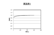
- FIG. 2 is a plot showing the results of changes in viscosity over time when the shear strength (shear rate: 1 / s) was changed for the bonding material according to Example 1, and the horizontal axis represents time (s). The vertical axis indicates the viscosity (Pa ⁇ s).
- FIG. 3 is a plot showing the results of change over time in the recovery rate obtained from FIG. 2, where the horizontal axis indicates time (s) and the vertical axis indicates the recovery rate. Note that 0 second in FIG. 3 corresponds to 120 seconds in FIG. On the other hand, FIG.
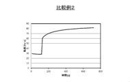
- FIG. 4 is a plot showing the results of changes in viscosity over time when the shear strength (shear rate: 1 / s) was changed for the bonding material according to Comparative Example 2, and the horizontal axis represents time. (S), vertical axis indicates viscosity (Pa ⁇ s).
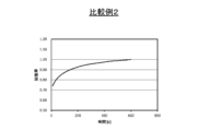
- FIG. 5 is a plot showing the results of the change over time in the recovery rate obtained from FIG. 4. The horizontal axis represents time (s) and the vertical axis represents the recovery rate. Note that 0 second in FIG. 5 corresponds to 120 seconds in FIG.
- Example 1 In Example 1 (FIG. 2), after the shear rate was reduced to 1 (1 / s) at once, the viscosity recovered very rapidly. As shown, the recovery rate at the start of measurement is 0.90 or more in FIG.
- Comparative Example 2 In Comparative Example 2 (FIG. 4), the speed of viscosity recovery is extremely slow. As shown in FIG. 5, it takes a considerable time even if the recovery rate is 0.90, for example. This slow recovery leads to fluctuations in the discharge amount, which ultimately leads to dispensing problems. However, in each example, the viscosity can be quickly recovered, and not only the dispensing property but also the bonding property can be improved. Further, as can be seen from the above results, the specified recovery rate in the bonding material is preferably high, specifically, preferably 0.80 or more at the start of measurement, and 0.85 or more. More preferred.
- Example 4 In Examples 4 to 7, Hinoact KF-1000 (Example 4) and MA-WAX-O (Examples) were used instead of BYK-R606 used as a cross-linking interparticle distance retaining agent in Examples 1 to 3. 5), Tsunodim 395 (Example 6) and castor hard (Example 7) were used for the test.
- the method for producing the first silver fine particles and the second silver fine particles is as described in Example 1, and other matters not specifically mentioned are as described in Example 1.
- Silver particles having a particle diameter of 0.6 ⁇ m (AG2-1C manufactured by DOWA Electronics) 51.09% by mass -Octanediol (2-ethyl-1,3-hexanediol manufactured by Wako Pure Chemical Industries, Ltd.) as the first solvent 1.49% by mass -1-dodecanol (manufactured by Tokyo Chemical Industry Co., Ltd.) 0.80% by mass as the second solvent 2-methyl-butane-1,3,4-triol (isoprenetriol B (IPTL-B)) (made by Nippon Terpene Chemical Co., Ltd.) as a third solvent 3.49% by mass ⁇ Butoxyethoxyacetic acid (BEA) as a dispersant (manufactured by Tokyo Chemical Industry Co., Ltd.) 0.50% by mass ⁇
- Viscosity of bonding material The viscosity of this bonding material (silver paste) at 25 ° C. was determined with a rheometer (rotary dynamic viscoelasticity measuring device) (HAAKE Rheo Stress 600 manufactured by Thermo, cone diameter 35 mm, cone having a cone angle of 2 ° was used). .
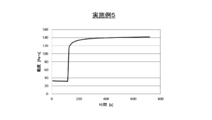
- FIG. 6 is a plot showing the results of changes in viscosity over time when the shear strength (shear rate: 1 / s) was changed for the bonding material according to Example 4 (Hinoact KF-1000).
- the axis represents time (s), and the vertical axis represents viscosity (Pa ⁇ s).
- FIG. 7 is a plot showing the results of the change over time in the recovery rate obtained from FIG. 6, with the horizontal axis indicating time (s) and the vertical axis indicating the recovery rate. Note that 0 second in FIG. 7 corresponds to 120 seconds in FIG.
- Example 5 MA-WAX-O
- Example 6 Tuunodaim 395
- the results correspond to FIGS. 10 and 11, and the results according to Example 7 (castor hard) correspond to FIGS.
- Example 2 Compared with Comparative Example 2, the viscosity was quickly recovered after the shear rate was reduced to 1 (1 / s) at once. As shown, the recovery rate at the start of measurement is 0.78 or more in any of the examples. In Examples 6 and 7, the speed of viscosity recovery is slower than that of Examples 4 and 5 (and Example 1) (for example, the time until the viscosity recovery rate becomes 0.95 is long), and the dispensing property is high. In this respect, the bonding materials of Examples 4 and 5 are superior.
- Example 4 In addition, in Example 4 (Hinoact KF-1000) and Example 5 (MA-WAX-O), the viscosity recovered rapidly.
Abstract
The purpose of the present invention is to provide a bonding material having both good dispensing properties and bondability, and a bonding method using the bonding material. Provided are: a bonding material that contains silver fine particles for which the average primary particle diameter is 130 nm or less, and a crosslinked-type interparticle-distance-maintaining agent that crosslinks between the silver fine particles and maintains a gap between the silver fine particles; and a bonding method using the bonding material.
Description
本発明は、接合材及びそれを用いた接合方法、特に銀微粒子を含有する接合材及びそれを用いた接合方法に関する。
The present invention relates to a bonding material and a bonding method using the same, and more particularly to a bonding material containing silver fine particles and a bonding method using the same.
金属は粒子径が微小になると、サイズ特有の物理特性を示すことが知られている。特にナノオーダーの粒子になると、バルク材とは異なる特性を示す場合がある。このような性質を利用し、ナノ金属粒子を使った異物質間の接合材料が提案されている。
Metals are known to exhibit size-specific physical properties when the particle size is reduced. In particular, nano-order particles may exhibit different properties from the bulk material. Utilizing such properties, bonding materials between different substances using nano metal particles have been proposed.
例えば特許文献1には、可能な限り単純な構成であっても接合強度が確保され、かつ接合強度のムラを低減すべく、マイクロトラック粒度分布測定装置で測定される、平均一次粒子径(D50径)0.5~3.0μmである銀微粒子と、平均一次粒子径が1~200nmであって、炭素数6の脂肪酸で被覆された銀微粒子と、これらを分散させる分散媒を含む接合材が開示されている。
For example, Patent Document 1 discloses that an average primary particle diameter (D50) measured by a microtrack particle size distribution measuring device is obtained in order to ensure bonding strength even with a simple configuration as much as possible and to reduce unevenness in bonding strength. Diameter) 0.5 to 3.0 μm of silver fine particles, an average primary particle diameter of 1 to 200 nm, silver fine particles coated with a fatty acid having 6 carbon atoms, and a bonding material containing a dispersion medium for dispersing them Is disclosed.
また特許文献2には、銀の含有率を高くしても接合面に均一に塗布することができ、緻密な接合層を形成することで、繰り返しヒートショックにも耐えるようにすべく、炭素数6以下のカルボン酸で被覆され平均一次粒子径が10~30nmの銀微粒子と、炭素数6以下のカルボン酸で被覆され平均一次粒子径が100~200nmの銀微粒子と、平均一次粒子径が0.3~3.0μmの銀微粒子と、リン酸エステル基を有する分散剤からなる接合材が開示されている。
Further, in Patent Document 2, even if the silver content is increased, it can be uniformly applied to the joint surface, and by forming a dense joint layer, the number of carbon atoms is to be able to withstand repeated heat shocks. Silver fine particles coated with a carboxylic acid having 6 or less and an average primary particle diameter of 10 to 30 nm, silver fine particles coated with a carboxylic acid having 6 or less carbon atoms and an average primary particle diameter of 100 to 200 nm, and an average primary particle diameter of 0 A bonding material comprising silver fine particles of 3 to 3.0 μm and a dispersant having a phosphate group is disclosed.
上記の各特許文献に代表される従来の接合材について本発明者らが鋭意検討を継続した結果、銀微粒子を含有する接合材を使用する際に、ディスペンス式印刷を行うとノズルから接合材を吐出する際の吐出量に少なからず変動が生じることが明らかとなった。以降、接合材の吐出量の変動をディスペンス性と呼び、吐出量の変動が少ない場合、ディスペンス性が良好である、と表現するものとする。なお、本明細書においては接合材(インクやペースト)にせん断力をかけてノズルから接合材を吐出して印刷をする方式をディスペンス式印刷と称する。
As a result of continuous studies by the present inventors on conventional bonding materials represented by the above-mentioned patent documents, when using a bonding material containing silver fine particles, when dispensing printing is performed, the bonding material is removed from the nozzle. It became clear that there was a considerable fluctuation in the discharge amount when discharging. Hereinafter, the variation in the ejection amount of the bonding material is referred to as “dispensing property”, and when the variation in the ejection amount is small, it is expressed that the dispensing property is good. In the present specification, a method of performing printing by applying a shearing force to a bonding material (ink or paste) and discharging the bonding material from a nozzle is referred to as dispense-type printing.
一方、上記の各特許文献に記載されるように接合材において微小なナノサイズの銀微粒子とミクロンサイズの銀粒子を併用することが知られている。これらの文献では接合性を接合強度で評価しているが、接合材には十分な強度で被接合物を接合することと同時に、これらの間の導通を確保することも求められる。接合材を焼結して接合層を形成した場合に、ボイドやクラックが存在しても一定の接合強度が確保できる場合があるが、そのような場合には導通が不十分となることが考えられるし、製品の加工工程においてボイドやクラックを起点として割れが発生することも考えられる。これらの事情を総合的に評価するには、接合層中にボイドやクラックが存在するかを評価することが適当であると本発明者らは考えた。本明細書では、接合層中にボイドやクラックが少ないこと、存在しないことを接合性が良好である、と表現することとする。
本発明者らが検討したところ、上記の微小なナノサイズの銀微粒子は前記接合性を良好にするのに有効であるが、ディスペンス性を悪化させてしまうことがわかってきた。また、ディスペンス性を改良するためには、上記の各特許文献で言うところの比較的大きな粒径を有する銀微粒子の割合を多くするなり粒径そのものを大きくすることが有効であることもわかってきた。ただ、そうすると今度は微小な銀微粒子の割合が小さくなり、形成される接合層の接合性が低下してしまうことが判明した。 On the other hand, as described in the above patent documents, it is known to use a combination of fine nano-sized silver fine particles and micron-sized silver particles in a bonding material. In these documents, the bondability is evaluated by the bonding strength. However, it is also required that the bonding material is bonded to the objects to be bonded with sufficient strength, and at the same time, the connection between them is ensured. When the bonding material is sintered to form a bonding layer, a certain bonding strength may be ensured even if voids or cracks exist. In such a case, it is considered that conduction is insufficient. In addition, it is conceivable that cracks are generated starting from voids and cracks in the product processing process. In order to comprehensively evaluate these circumstances, the present inventors considered that it is appropriate to evaluate whether voids or cracks exist in the bonding layer. In the present specification, the fact that there are few voids and cracks in the bonding layer and the absence of the bonding layer is expressed as good bonding properties.
As a result of investigations by the present inventors, it has been found that the above-mentioned fine nano-sized silver fine particles are effective in improving the bonding property but deteriorate the dispensing property. Also, in order to improve the dispensing properties, it has been found effective to increase the proportion of silver fine particles having a relatively large particle diameter as referred to in each of the above-mentioned patent documents and to increase the particle diameter itself. It was. However, it has now been found that the proportion of fine silver particles is reduced and the bonding properties of the formed bonding layer are lowered.
そこで本発明は、このようにトレードオフの関係にあるディスペンス性と接合性が共に良好な接合材及びそれを用いた接合方法を提供することを目的とする。
Therefore, an object of the present invention is to provide a bonding material having a good trade-off relationship and good dispensing properties and bonding properties, and a bonding method using the same.
本発明者らは上記課題を解決するために鋭意検討した結果、接合材に銀微粒子同士の間隔を適切に保持する機能を有する物質を添加することによって、ディスペンス性と接合性の両立を実現することができることを見出し、本発明を完成するに至った。
As a result of intensive studies to solve the above-mentioned problems, the present inventors have realized a balance between dispenseability and bondability by adding a substance having a function of appropriately maintaining the interval between silver fine particles to the bonding material. As a result, the present invention has been completed.
本発明の第1の態様は、
平均一次粒子径が130nm以下である銀微粒子と、
前記銀微粒子間を架橋して前記銀微粒子同士の間隔を保持する架橋型粒子間距離保持剤と、
を含有する、接合材である。 The first aspect of the present invention is:
Silver fine particles having an average primary particle diameter of 130 nm or less;
A crosslinkable interparticle distance retention agent that crosslinks between the silver fine particles and maintains the spacing between the silver fine particles;
It is a joining material containing.
本発明の第2の態様は、第1の態様に記載の発明において、
前記架橋型粒子間距離保持剤は、下記式(I)で表される化合物αである。

但し、式(I)において、Rは2~4価の有機基であり、
A及びBは、ヒドロキシル基、アミノ基、カルボキシル基又はチオール基であり、Aが2つ存在する場合、それらは互いに同一であっても異なっていてもよく、Bが2つ存在する場合、それらは互いに同一であっても異なっていてもよく、
Rを構成する最も長い直鎖部分において、Aと結合する原子1と、Bと結合する原子2との間の部分のうち最長のものを第一主鎖としたとき、前記第一主鎖の鎖構成原子数は10~180である。 According to a second aspect of the present invention, in the invention according to the first aspect,
The crosslinkable interparticle distance holding agent is a compound α represented by the following formula (I).
However, in the formula (I), R is a divalent to tetravalent organic group,
A and B are a hydroxyl group, an amino group, a carboxyl group or a thiol group, and when two A are present, they may be the same or different from each other, and when two B are present, May be the same or different from each other,
In the longest straight chain portion constituting R, the longest of the portions between theatom 1 bonded to A and the atom 2 bonded to B is defined as the first main chain. The number of chain constituent atoms is 10 to 180.
前記架橋型粒子間距離保持剤は、下記式(I)で表される化合物αである。
但し、式(I)において、Rは2~4価の有機基であり、
A及びBは、ヒドロキシル基、アミノ基、カルボキシル基又はチオール基であり、Aが2つ存在する場合、それらは互いに同一であっても異なっていてもよく、Bが2つ存在する場合、それらは互いに同一であっても異なっていてもよく、
Rを構成する最も長い直鎖部分において、Aと結合する原子1と、Bと結合する原子2との間の部分のうち最長のものを第一主鎖としたとき、前記第一主鎖の鎖構成原子数は10~180である。 According to a second aspect of the present invention, in the invention according to the first aspect,
The crosslinkable interparticle distance holding agent is a compound α represented by the following formula (I).
However, in the formula (I), R is a divalent to tetravalent organic group,
A and B are a hydroxyl group, an amino group, a carboxyl group or a thiol group, and when two A are present, they may be the same or different from each other, and when two B are present, May be the same or different from each other,
In the longest straight chain portion constituting R, the longest of the portions between the
本発明の第3の態様は、第2の態様に記載の発明において、
前記式(I)におけるA及びBのうち少なくとも一つは、ヒドロキシル基、アミノ基又はチオール基であり、
前記式(I)におけるRを構成する最も長い直鎖部分が側鎖を有し、前記側鎖における最も長い直鎖部分の鎖構成原子数は、前記第一主鎖の鎖構成原子数の1/3以下である。 According to a third aspect of the present invention, in the invention according to the second aspect,
At least one of A and B in the formula (I) is a hydroxyl group, an amino group or a thiol group,
The longest straight chain part constituting R in the formula (I) has a side chain, and the number of chain constituent atoms of the longest straight chain part in the side chain is 1 of the number of chain constituent atoms of the first main chain. / 3 or less.
本発明の第4の態様は、第2又は第3の態様に記載の発明において、
前記式(I)におけるRを構成する最も長い直鎖部分が側鎖を有し、前記側鎖は炭素数1~12の炭化水素基であり、A及びBは前記側鎖に結合していてもよい。 According to a fourth aspect of the present invention, in the invention according to the second or third aspect,
The longest straight chain portion constituting R in the formula (I) has a side chain, the side chain is a hydrocarbon group having 1 to 12 carbon atoms, and A and B are bonded to the side chain. Also good.
本発明の第5の態様は、第2~第4のいずれかの態様に記載の発明において、
前記式(I)において、前記化合物αを構成する最も長い直鎖部分を第二主鎖としたとき、前記第一主鎖、及び前記第二主鎖の鎖構成原子(鎖末端の原子を除く)が、-CH2-,-CH(Ra)-,-C(Ra)2-,-CX2-,-CX(Ra)-,-CH=,-C(Ra)=,=C=,-CO-,-NH-,-N(Ra)-,-N=,-N(OH)-,-O-,-S-,-SO2-から選ばれる基を形成している。但し、Raは、Rを構成する最も長い直鎖部分が有する側鎖であり、Xはハロゲンである。 According to a fifth aspect of the present invention, in the invention according to any one of the second to fourth aspects,
In the formula (I), when the longest straight chain portion constituting the compound α is the second main chain, the first main chain and the chain constituent atoms of the second main chain (excluding the atoms at the chain end) ) Is —CH 2 —, —CH (R a ) —, —C (R a ) 2 —, —CX 2 —, —CX (R a ) —, —CH═, —C (R a ) =, ═C═, —CO—, —NH—, —N (R a ) —, —N═, —N (OH) —, —O—, —S—, —SO 2 — is formed. ing. However, R a is the side chain having the longest linear portion constituting the R, X is a halogen.
本発明の第6の態様は、第2の態様に記載の発明において、
前記化合物αは、下記式(II)~(IV)のいずれかである。

但し、式(II)において、v及びyはそれぞれ独立に1~2の整数であり、wは0~10の整数であり、xは14~40の整数である。

但し、式(III)において、複数存在するkはそれぞれ独立に3~10の整数であり、複数存在するlはそれぞれ独立に6~16の整数であり、mは2~8の整数である。

但し、式(IV)において、n及びsはそれぞれ独立に、3~10の整数であり、p及びrはそれぞれ独立に6~18の整数であり、qは2~10の整数である。 According to a sixth aspect of the present invention, in the invention described in the second aspect,
The compound α is any one of the following formulas (II) to (IV).
However, in the formula (II), v and y are each independently an integer of 1 to 2, w is an integer of 0 to 10, and x is an integer of 14 to 40.
However, in the formula (III), a plurality of ks each independently represents an integer of 3 to 10, each of a plurality of ls independently represents an integer of 6 to 16, and m is an integer of 2 to 8.
However, in the formula (IV), n and s are each independently an integer of 3 to 10, p and r are each independently an integer of 6 to 18, and q is an integer of 2 to 10.
前記化合物αは、下記式(II)~(IV)のいずれかである。
但し、式(II)において、v及びyはそれぞれ独立に1~2の整数であり、wは0~10の整数であり、xは14~40の整数である。
但し、式(III)において、複数存在するkはそれぞれ独立に3~10の整数であり、複数存在するlはそれぞれ独立に6~16の整数であり、mは2~8の整数である。
但し、式(IV)において、n及びsはそれぞれ独立に、3~10の整数であり、p及びrはそれぞれ独立に6~18の整数であり、qは2~10の整数である。 According to a sixth aspect of the present invention, in the invention described in the second aspect,
The compound α is any one of the following formulas (II) to (IV).
However, in the formula (II), v and y are each independently an integer of 1 to 2, w is an integer of 0 to 10, and x is an integer of 14 to 40.
However, in the formula (III), a plurality of ks each independently represents an integer of 3 to 10, each of a plurality of ls independently represents an integer of 6 to 16, and m is an integer of 2 to 8.
However, in the formula (IV), n and s are each independently an integer of 3 to 10, p and r are each independently an integer of 6 to 18, and q is an integer of 2 to 10.
本発明の第7の態様は、第1~第6のいずれかの態様に記載の発明において、
平均一次粒子径が0.3~10μmである銀粒子を更に含有する。 According to a seventh aspect of the present invention, in the invention according to any one of the first to sixth aspects,
It further contains silver particles having an average primary particle size of 0.3 to 10 μm.
平均一次粒子径が0.3~10μmである銀粒子を更に含有する。 According to a seventh aspect of the present invention, in the invention according to any one of the first to sixth aspects,
It further contains silver particles having an average primary particle size of 0.3 to 10 μm.
本発明の第8の態様は、第1~第7のいずれかの態様に記載の発明において、
前記銀微粒子は有機化合物により被覆されている。 According to an eighth aspect of the present invention, in the invention according to any one of the first to seventh aspects,
The silver fine particles are coated with an organic compound.
前記銀微粒子は有機化合物により被覆されている。 According to an eighth aspect of the present invention, in the invention according to any one of the first to seventh aspects,
The silver fine particles are coated with an organic compound.
本発明の第9の態様は、第1~第8のいずれかの態様に記載の発明において、
極性溶媒を更に含有する。 According to a ninth aspect of the present invention, in the invention according to any one of the first to eighth aspects,
It further contains a polar solvent.
極性溶媒を更に含有する。 According to a ninth aspect of the present invention, in the invention according to any one of the first to eighth aspects,
It further contains a polar solvent.
本発明の第10の態様は、第1~第9のいずれかの態様に記載の発明において、
酸系分散剤を更に含有する。 According to a tenth aspect of the present invention, in the invention according to any one of the first to ninth aspects,
It further contains an acid-based dispersant.
酸系分散剤を更に含有する。 According to a tenth aspect of the present invention, in the invention according to any one of the first to ninth aspects,
It further contains an acid-based dispersant.
本発明の第11の態様は、第1~第10のいずれかの態様に記載の発明に係る接合材を被接合物間に介在させて加熱することにより、前記接合材から接合層を形成し、これにより被接合物同士を接合する、接合方法である。
According to an eleventh aspect of the present invention, a bonding layer is formed from the bonding material by heating the bonding material according to any one of the first to tenth aspects interposed between objects to be bonded. This is a joining method for joining the objects to be joined together.
本発明によれば、ディスペンス性と接合性が共に良好な接合材及びそれを用いた接合方法を提供できる。
According to the present invention, it is possible to provide a bonding material with good dispensing properties and bonding properties and a bonding method using the same.
以下、本発明を詳細に説明する。なお、本明細書において「~」は所定の値以上かつ所定の値以下を指す。
Hereinafter, the present invention will be described in detail. In this specification, “˜” refers to a value that is greater than or equal to a predetermined value and less than or equal to a predetermined value.
本実施形態においては以下の順番で説明を行う。
1.接合材
1-1.銀微粒子
1-2.銀粒子
1-3.架橋型粒子間距離保持剤
1-4.溶剤
1-5.分散剤
1-6.その他
1-7.接合材の製造方法
2.接合材を用いた接合方法 In the present embodiment, description will be given in the following order.
1. Bonding material 1-1. Silver fine particles 1-2. Silver particles 1-3. Cross-linking interparticle distance retaining agent 1-4. Solvent 1-5. Dispersant 1-6. Others 1-7. 1. Manufacturing method of bonding material Joining method using joining material
<1.接合材>
本実施形態における接合材(銀微粒子を含む銀ペーストである)を構成する各要素について説明する。 <1. Bonding material>
Each element constituting the bonding material (a silver paste containing silver fine particles) in the present embodiment will be described.
本実施形態における接合材(銀微粒子を含む銀ペーストである)を構成する各要素について説明する。 <1. Bonding material>
Each element constituting the bonding material (a silver paste containing silver fine particles) in the present embodiment will be described.
1-1.銀微粒子
本実施形態において使用する銀微粒子は、平均一次粒子径が130nm以下であれば特に限定は無い。また銀微粒子の作製手法としては公知のものを使用しても構わないし、平均一次粒子径が130nm以下である公知の銀微粒子を使用しても構わない。 1-1. Silver fine particles The silver fine particles used in the present embodiment are not particularly limited as long as the average primary particle diameter is 130 nm or less. As a method for producing silver fine particles, a known method may be used, or known silver fine particles having an average primary particle diameter of 130 nm or less may be used.
本実施形態において使用する銀微粒子は、平均一次粒子径が130nm以下であれば特に限定は無い。また銀微粒子の作製手法としては公知のものを使用しても構わないし、平均一次粒子径が130nm以下である公知の銀微粒子を使用しても構わない。 1-1. Silver fine particles The silver fine particles used in the present embodiment are not particularly limited as long as the average primary particle diameter is 130 nm or less. As a method for producing silver fine particles, a known method may be used, or known silver fine particles having an average primary particle diameter of 130 nm or less may be used.
平均一次粒子径が130nm以下の銀微粒子は接合性において良好で、特に平均一次粒子径が1~40nmの銀微粒子は、接合性に優れる。この接合性の観点からは、銀微粒子の平均一次粒子径は5~30nmであるのがより好ましく、10~20nmであるのがさらに好ましい。
また、平均一次粒子径が41nm以上の銀微粒子は、40nm以下の銀微粒子ほどではないが接合性が良好であり、同時に接合材の粘度を(40nm以下の銀微粒子を添加した場合と比較して)低下させ、接合材を印刷しやすくすることができる。このような接合性と印刷適性のバランスの観点からは、銀微粒子の平均一次粒子径は50~115nmであるのが好ましく、55~100nmであるのがさらに好ましい。
なお、本実施形態においては、接合性及び印刷適性を考慮して、銀微粒子として、平均一次粒子径が1~40nmの銀微粒子と平均一次粒子径が41~130nmの銀微粒子とを組み合わせて使用してもよい。 Silver fine particles having an average primary particle size of 130 nm or less have good bonding properties, and silver fine particles having an average primary particle size of 1 to 40 nm are particularly excellent in bonding properties. From the viewpoint of this bonding property, the average primary particle diameter of the silver fine particles is more preferably 5 to 30 nm, and further preferably 10 to 20 nm.
Further, silver fine particles having an average primary particle size of 41 nm or more are not as good as silver fine particles of 40 nm or less, but have good bonding properties, and at the same time, the viscosity of the bonding material (compared with the case where silver fine particles of 40 nm or less are added). ) Can be reduced to facilitate printing of the bonding material. From the viewpoint of such a balance between bondability and printability, the average primary particle size of the silver fine particles is preferably 50 to 115 nm, and more preferably 55 to 100 nm.
In the present embodiment, in consideration of bondability and printability, silver fine particles are used in combination with silver fine particles having an average primary particle diameter of 1 to 40 nm and silver fine particles having an average primary particle diameter of 41 to 130 nm. May be.
なお、本明細書中における金属粒子(銀微粒子や後述の銀粒子)の平均一次粒子径は、金属粒子の透過型電子顕微鏡写真(TEM像)又は走査型電子顕微鏡写真(SEM像)から求められる一次粒子径の平均値をいう。
更に具体的に言うと、例えば、透過型電子顕微鏡(TEM)(日本電子株式会社製のJEM-1011)又は走査型電子顕微鏡(SEM)(日立ハイテクノロジーズ株式会社製のS-4700)により金属粒子を所定の倍率で観察した像(SEM像又はTEM像)上の100個以上の任意の金属粒子の一次粒子径(金属粒子と面積が同じ円の径)から算出することができる。この金属粒子の平均一次粒子径の算出は、例えば、画像解析ソフト(旭化成エンジニアリング株式会社製のA像くん(登録商標))により行うことができる。 In addition, the average primary particle diameter of the metal particles (silver fine particles and silver particles described later) in this specification is determined from a transmission electron micrograph (TEM image) or a scanning electron micrograph (SEM image) of the metal particles. The average primary particle size.
More specifically, for example, metal particles can be obtained using a transmission electron microscope (TEM) (JEM-1011 manufactured by JEOL Ltd.) or a scanning electron microscope (SEM) (S-4700 manufactured by Hitachi High-Technologies Corporation). Can be calculated from the primary particle diameter of 100 or more arbitrary metal particles (the diameter of a circle having the same area as the metal particles) on an image (SEM image or TEM image) observed at a predetermined magnification. The average primary particle diameter of the metal particles can be calculated by, for example, image analysis software (A image-kun (registered trademark) manufactured by Asahi Kasei Engineering Co., Ltd.).
本発明に使用される銀微粒子は平均一次粒子径が130nm以下と小さくて凝集し易いため、有機化合物で被覆されているのが好ましい。なお、この有機化合物としては銀微粒子を被覆可能な公知のものを使用して構わない。なお有機化合物としては、低温(例えば170~400℃)での焼成により十分に銀微粒子から分離して銀微粒子同士の焼結を阻害しないように、炭素数8以下、好ましくは炭素数2~6の飽和脂肪酸もしくは不飽和脂肪酸やアミンが好ましい。このような脂肪酸やアミンの例として、ヘキサン酸、ソルビン酸、ヘキシルアミン及びオクチルアミンが挙げられる。
The silver fine particles used in the present invention are preferably coated with an organic compound because the average primary particle diameter is as small as 130 nm or less and easily aggregates. In addition, as this organic compound, you may use the well-known thing which can coat | cover silver fine particles. The organic compound has 8 or less carbon atoms, preferably 2 to 6 carbon atoms so as not to be sufficiently separated from the silver fine particles by firing at a low temperature (for example, 170 to 400 ° C.) to prevent sintering of the silver fine particles. Of these, saturated fatty acids, unsaturated fatty acids and amines are preferred. Examples of such fatty acids and amines include hexanoic acid, sorbic acid, hexylamine and octylamine.
以上説明した銀微粒子の本実施形態の接合材中における含有量は、適切な接合力を発現する観点から、4~97質量%であることが好ましく、4~85質量%であることがより好ましい。
The content of the silver fine particles described above in the bonding material of the present embodiment is preferably 4 to 97% by mass, and more preferably 4 to 85% by mass from the viewpoint of developing an appropriate bonding force. .
1-2.銀粒子
本実施形態の接合材には、平均一次粒子径が0.3μm~10μmの銀粒子を添加してもよい。銀粒子を添加すると(添加せずに銀微粒子だけで金属粒子を構成した場合に比較して)接合材の粘度を低下させることができ、接合材を印刷し易くすることができる。このような印刷適性の観点から、銀粒子の平均一次粒子径は、0.3~5μmであるのがより好ましく、0.3~3μmであるのが更に好ましい。
なお、この銀粒子は分散性向上などのため有機化合物で被覆されていてもよく、その際に、銀粒子を炭素数20以下の有機化合物(有機化合物の炭素数は通常2以上である。)にて被覆するのが好ましい。
銀粒子の本実施形態の接合材中における含有量は、銀微粒子の配合量が少なくなって接合性が損なわれることなく、印刷適性を確保する観点から、20~80質量%であることが好ましい。
また、銀粒子を使用する場合の本実施形態の接合材中における銀微粒子及び銀粒子の合計の含有量は、以上の観点から、85~97質量%であるのが好ましく、87~95質量%であるのがさらに好ましい。 1-2. Silver Particles Silver particles having an average primary particle size of 0.3 μm to 10 μm may be added to the bonding material of the present embodiment. When silver particles are added (compared to the case where metal particles are composed only of silver fine particles without being added), the viscosity of the bonding material can be reduced, and the bonding material can be easily printed. From the viewpoint of such printability, the average primary particle diameter of the silver particles is more preferably 0.3 to 5 μm, still more preferably 0.3 to 3 μm.
In addition, this silver particle may be coat | covered with the organic compound for the dispersibility improvement etc., and in that case, the silver particle is an organic compound having 20 or less carbon atoms (the carbon number of the organic compound is usually 2 or more). It is preferable to coat with.
The content of the silver particles in the bonding material of the present embodiment is preferably 20 to 80% by mass from the viewpoint of ensuring printability without reducing the compounding amount of the silver fine particles and impairing the bonding properties. .
From the above viewpoint, the total content of the silver fine particles and the silver particles in the bonding material of this embodiment when using silver particles is preferably 85 to 97% by mass, and 87 to 95% by mass. More preferably.
1-3.架橋型粒子間距離保持剤
本実施形態における接合材は、銀微粒子間を架橋して銀微粒子同士の間隔を保持する架橋型粒子間距離保持剤を含有する。銀微粒子間を架橋することで銀微粒子同士の物理的な間隔が保持されて、接合材の使用前において銀微粒子が凝集するのを防止して分散状態を維持することができる。同時にこの架橋により、せん断力をかけられたときには架橋が外れたり弱まることで粘度が低下してディスペンス式印刷で吐出されやすくなり、一方印刷が終了してせん断力が取り除かれたときには、通常のチキソ性を有するインクでも粘度が回復するところ、架橋が復活することにより前記の粘度回復がより早期に起こるものと考えられる(後述の実施例参照)。このようにして架橋型粒子間距離保持剤は接合材のディスペンス性を良好にするものと考えられる。
さらに架橋型粒子間距離保持剤は、焼成時(例えば170~400℃で加熱される)においては、加熱により揮散するか、少なくとも分子運動が活発となって銀微粒子から離脱しやすくなり、銀微粒子の焼結を阻害しないため、良好な接合性を実現できる。なお、接合材中に銀微粒子以外の金属粒子が存在する場合は、そのような金属粒子同士、または金属粒子と銀微粒子とを架橋型粒子間距離保持剤が架橋し得る。
架橋型粒子間距離保持剤としては、銀微粒子同士を架橋(連結)して上記のような機能を奏するものであれば、特に限定無く使用可能である。この架橋としては、例えば銀そのものと連結しして、銀微粒子同士が架橋型粒子間距離保持剤を介して連結されるものであればよい。
架橋型粒子間距離保持剤は、銀微粒子同士を架橋するため、銀微粒子と親和性のある官能基(例えばヒドロキシル基、アミノ基、チオール基、カルボキシル基)を複数有する。また架橋型粒子間距離保持剤は銀微粒子同士の間隔を保持するものの、その間隔が長いと、銀微粒子同士に間があいており接合の焼結時にボイドが発生してクラック等の原因となることが考えられるため、架橋型粒子間距離保持剤としては、銀微粒子同士をこのような点から適切な間隔に保持する分子長、分子構造のものが好ましい。
このような架橋型粒子間距離保持剤を使用することで、銀微粒子を含む接合材において、良好なディスペンス性と接合性を両立することができる。 1-3. Crosslinkable interparticle distance retainer The bonding material in the present embodiment contains a crosslinkable interparticle distance retainer that crosslinks between the silver fine particles and maintains the distance between the silver fine particles. By cross-linking the silver fine particles, the physical distance between the silver fine particles is maintained, so that the silver fine particles can be prevented from aggregating before the bonding material is used, and the dispersed state can be maintained. At the same time, due to this cross-linking, when the shear force is applied, the cross-link breaks or weakens, so that the viscosity decreases and it is easy to be dispensed by dispensing printing. Even when the viscosity of the ink is restored, it is considered that the above-described viscosity recovery occurs earlier due to the restoration of the cross-linking (see Examples described later). Thus, it is considered that the cross-linking interparticle distance maintaining agent improves the dispensing property of the bonding material.
Further, the cross-link type interparticle distance holding agent is volatilized by heating during firing (for example, heated at 170 to 400 ° C.), or at least the molecular motion becomes active and is easily detached from the silver fine particles. Therefore, good bonding properties can be realized. When metal particles other than silver fine particles are present in the bonding material, such a metal particle, or the metal particles and silver fine particles can be cross-linked by a crosslinkable interparticle distance holding agent.
Any crosslinkable interparticle distance retaining agent can be used without particular limitation as long as it is capable of crosslinking (connecting) the silver fine particles and exhibiting the above functions. As this cross-linking, for example, any silver fine particles may be connected to each other through a cross-linking inter-particle distance holding agent by being connected to silver itself.
The crosslinkable interparticle distance holding agent has a plurality of functional groups (for example, a hydroxyl group, an amino group, a thiol group, and a carboxyl group) having an affinity for the silver fine particles in order to crosslink the silver fine particles. The cross-link type interparticle distance retention agent retains the spacing between the silver particles, but if the spacing is long, the silver particles are spaced from each other, causing voids during sintering and causing cracks and the like. Therefore, as the cross-linking interparticle distance holding agent, those having a molecular length and a molecular structure that hold silver fine particles at appropriate intervals from such a point are preferable.
By using such a cross-linking interparticle distance holding agent, it is possible to achieve both good dispensing properties and bonding properties in a bonding material containing silver fine particles.
前記架橋型粒子間距離保持剤は、例えば、下記式(I)で表される化合物αである。

The crosslinkable interparticle distance holding agent is, for example, a compound α represented by the following formula (I).
前記式(I)において、Rは2~4価の有機基であり、A及びBは、ヒドロキシル基、アミノ基、カルボキシル基又はチオール基であり、そして、Rを構成する最も長い直鎖部分において、Aと結合する原子1と、Bと結合する原子2との間の部分のうち最長のものを第一主鎖としたとき、前記第一主鎖の鎖構成原子数は10~180である。ここで、Aが2つ存在する場合、2つのAは互いに同一であっても異なっていてもよい。Bについても同様である。また、A及びBはRの最も長い直鎖部分の任意の個所に結合していてよく、前記直鎖部分の末端に結合していなくてもよい。
In the formula (I), R is a divalent to tetravalent organic group, A and B are a hydroxyl group, an amino group, a carboxyl group, or a thiol group, and in the longest linear portion constituting R , When the longest of the portions between the atom 1 bonded to A and the atom 2 bonded to B is the first main chain, the number of chain constituent atoms of the first main chain is 10 to 180 . Here, when two A exist, two A may mutually be same or different. The same applies to B. A and B may be bonded to an arbitrary position of the longest straight chain portion of R, and may not be bonded to the end of the straight chain portion.
このとき、Rは側鎖を有していてもよい。A及びBはこの側鎖に結合していてもよい。
At this time, R may have a side chain. A and B may be bonded to this side chain.
また、上記の第一主鎖の定義は、AやBが複数ある場合は、その最も分子末端側で第一主鎖を見ることを意味する。
In addition, the definition of the first main chain described above means that when there are a plurality of A and B, the first main chain is seen on the most molecular end side.
また、第一主鎖の鎖構成原子数が10~180であることにより、AとBがある程度離間しており、上述の架橋型粒子間距離保持剤としての、銀微粒子同士を適切な間隔に保持する機能を好適に発揮する。この機能の観点から、第一主鎖の鎖構成原子数は好ましくは20~120である。
In addition, since the number of atoms constituting the first main chain is 10 to 180, A and B are separated to some extent, and the silver fine particles as the above-mentioned cross-linking interparticle distance holding agent are arranged at appropriate intervals. The function to hold | maintain suitably is demonstrated. From the viewpoint of this function, the number of atoms constituting the first main chain is preferably 20 to 120.
In addition, since the number of atoms constituting the first main chain is 10 to 180, A and B are separated to some extent, and the silver fine particles as the above-mentioned cross-linking interparticle distance holding agent are arranged at appropriate intervals. The function to hold | maintain suitably is demonstrated. From the viewpoint of this function, the number of atoms constituting the first main chain is preferably 20 to 120.
なお、第一主鎖においては、“Aと結合する原子1と、Bと結合する原子2との間の部分のうち最長のもの”という規定に従い、第一主鎖における側鎖は鎖構成原子数にカウントしない。
In the first main chain, the side chain in the first main chain is a chain constituent atom in accordance with the definition of “the longest portion between the atom 1 bonded to A and the atom 2 bonded to B”. Don't count in numbers.
また、鎖構成原子とは2価以上の原子であって、2つ以上の2価以上の原子と結合している原子をいう。なおこの鎖構成原子には、AとBを構成する2価の原子(例えばO,N,C,S)が含まれるものとする。この鎖構成原子数が多いほど、長い鎖とみなす。
The chain constituent atom is a divalent or higher valent atom and is an atom bonded to two or more divalent or higher valent atoms. The chain constituent atoms include divalent atoms constituting A and B (for example, O, N, C, S). The larger the number of chain constituent atoms, the longer the chain.
また、前記式(I)におけるA及びBのうち少なくとも一つは、ヒドロキシル基、アミノ基又はチオール基であり、前記式(I)におけるRを構成する最も長い直鎖部分が側鎖を有し、前記側鎖における最も長い直鎖部分の鎖構成原子数は、前記第一主鎖の鎖構成原子数の1/3以下であるのが好ましい。この場合、後述の実施例に示す接合材の粘度の回復において、回復が開始して、短時間で接合材の元の粘度に回復することができる。また、このときの側鎖における最も長い直鎖部分の鎖構成原子数は、前記第一主鎖の鎖構成原子数の1/100以上であることが好ましい。なお、側鎖における最も長い直鎖部分の鎖構成原子は第一主鎖における鎖構成原子と同様であり、側鎖末端の、Hと結合した2価以上の原子を含むものとする。
In addition, at least one of A and B in the formula (I) is a hydroxyl group, an amino group or a thiol group, and the longest straight chain portion constituting R in the formula (I) has a side chain. The number of chain constituent atoms of the longest straight chain portion in the side chain is preferably 1/3 or less of the number of chain constituent atoms of the first main chain. In this case, in the recovery of the viscosity of the bonding material shown in the examples described later, the recovery starts, and the original viscosity of the bonding material can be recovered in a short time. Further, the number of chain constituent atoms of the longest straight chain portion in the side chain at this time is preferably 1/100 or more of the number of chain constituent atoms of the first main chain. The chain constituent atom of the longest straight chain portion in the side chain is the same as the chain constituent atom in the first main chain, and includes a divalent or higher-valent atom bonded to H at the end of the side chain.
上記例において特に好ましいのは、前記の接合材の粘度の早期回復の観点や接合性の観点から、AとBの全てがヒドロキシル基、アミノ基又はチオール基である場合であり、これらの観点からAとBの全てがヒドロキシル基であることが最も好ましい。
Particularly preferred in the above examples is the case where all of A and B are hydroxyl groups, amino groups or thiol groups, from the viewpoint of early recovery of the viscosity of the bonding material and the viewpoint of bonding properties, from these viewpoints. Most preferably, all of A and B are hydroxyl groups.
また、前記式(I)におけるRを構成する最も長い直鎖部分が側鎖を有する場合において、前記側鎖の例としては炭素数1~12(好ましくは2~8)の炭化水素基が挙げられる。なお、この炭化水素基は飽和又は不飽和であってもよく、分岐を有してもよい。
In the case where the longest straight chain portion constituting R in the formula (I) has a side chain, examples of the side chain include hydrocarbon groups having 1 to 12 carbon atoms (preferably 2 to 8 carbon atoms). It is done. In addition, this hydrocarbon group may be saturated or unsaturated, and may have a branch.
前記式(I)において、前記化合物αを構成する最も長い直鎖部分を第二主鎖としたとき、第二主鎖と第一主鎖の鎖構成原子数の差が、第二主鎖の鎖構成原子数の1/4以下であることが好ましい。この場合、AとBは化合物αの分子末端(前記差が0)又はその近傍の位置にあり、銀微粒子と作用しやすい。なお、第二主鎖が“化合物α”自体における最も長い直鎖部分のことを指すのに対し、第一主鎖は、繰り返しになるが“R”を構成する最も長い直鎖部分のうち、Aと結合する原子1と、Bと結合する原子2との間の部分のうち最長のものを指す。
In the formula (I), when the longest straight chain part constituting the compound α is the second main chain, the difference in the number of atoms constituting the second main chain and the first main chain is The number of atoms constituting the chain is preferably ¼ or less. In this case, A and B are at the molecular ends of the compound α (the difference is 0) or in the vicinity thereof, and easily act with silver fine particles. The second main chain refers to the longest straight chain portion in the “compound α” itself, whereas the first main chain repeats the longest straight chain portion constituting “R”, This refers to the longest portion between the atom 1 bonded to A and the atom 2 bonded to B.
第一主鎖及び第二主鎖の鎖構成原子は、好ましくはC,N,O,又はSであり、より好ましくはC,N,又はOである。また、好ましくは第一主鎖及び第二主鎖が、飽和又は不飽和である。
The chain constituent atoms of the first main chain and the second main chain are preferably C, N, O, or S, and more preferably C, N, or O. In addition, the first main chain and the second main chain are preferably saturated or unsaturated.
前記第一主鎖、及び前記第二主鎖のより具体的な例について説明すると、これらの鎖構成原子が、-CH2-,-CH(Ra)-,-C(Ra)2-,-CX2-,-CX(Ra)-,-CH=,-C(Ra)=,=C=,-CO-,-NH-,-N(Ra)-,-N=,-N(OH)-,-O-,-S-,-SO2-から選ばれる基を形成しているものが挙げられる。但し、Raは上記で説明したRの側鎖であり、Xはハロゲンである。なお、これらの中でも、架橋型粒子間距離保持剤としての機能の観点から、-CH2-,-CH(Ra)-,-C(Ra)2-,-CH=,-C(Ra)=,-CO-,-NH-,-N(Ra)-,-O-から選ばれる基が好ましい。
More specific examples of the first main chain and the second main chain will be described. These chain constituent atoms are represented by —CH 2 —, —CH (R a ) —, —C (R a ) 2 —. , -CX 2- , -CX (R a )-, -CH =, -C (R a ) =, = C =, -CO-, -NH-, -N (R a )-, -N =, Examples thereof include those forming a group selected from —N (OH) —, —O—, —S—, and —SO 2 —. However, Ra is the side chain of R demonstrated above, and X is a halogen. Of these, —CH 2 —, —CH (R a ) —, —C (R a ) 2 —, —CH═, —C (R) are preferable from the viewpoint of the function as a cross-linking interparticle distance retention agent. a ) =, —CO—, —NH—, —N (R a ) —, —O— are preferred.
前記式(I)で表される化合物αとして特に好ましいものの具体的な例を以下に列挙する。
Specific examples of particularly preferable compounds α represented by the formula (I) are listed below.
前記化合物αは、好ましくは下記式(II)~(IV)のいずれかで表される化合物である。

但し、式(II)において、v及びyはそれぞれ独立に1~2の整数であり、wは0~10の整数(ディスペンス性と接合性の両立の観点から好ましくは0~8の整数)であり、xは14~40の整数(ディスペンス性と接合性の両立の観点から好ましくは18~36の整数)である。-(CH=CH)w-(CH2)x-は、(CH=CH)がw個連続で連結し、続いて(CH2)がx個連続で連結したブロック状の構造であってもよいし、これらがランダムに並んだランダム状の構造であってもよい。
この式(II)の化合物の具体的な商品名としては、BYK-R606(ビックケミー・ジャパン株式会社)が挙げられる。

但し、式(III)において、複数存在するkはそれぞれ独立に3~10の整数(ディスペンス性と接合性の両立の観点から好ましくは4~8の整数)であり、複数存在するlはそれぞれ独立に6~16の整数(ディスペンス性と接合性の両立の観点から好ましくは8~12の整数)であり、mは2~8の整数(ディスペンス性と接合性の両立の観点から好ましくは3~6の整数)である。
この式(III)の具体的な商品名としては、ヒノアクトKF-1000(川研ファインケミカル株式会社)が挙げられる。

但し、式(IV)において、n及びsはそれぞれ独立に、3~10の整数(ディスペンス性と接合性の両立の観点から好ましくは4~8の整数)であり、p及びrはそれぞれ独立に6~18の整数(ディスペンス性と接合性の両立の観点から好ましくは8~14の整数)であり、qは2~10の整数(ディスペンス性と接合性の両立の観点から好ましくは2~6の整数)である。
この式(IV)の化合物の具体的な商品名としては、MA-WAX-O(ケイエフ・トレーディング株式会社)が挙げられる。
以上説明した式(II)~(IV)の化合物の中でも、接合性及びディスペンス性の観点から、式(II)で表される化合物が特に好ましい。 The compound α is preferably a compound represented by any one of the following formulas (II) to (IV).
However, in the formula (II), v and y are each independently an integer of 1 to 2, and w is an integer of 0 to 10 (preferably an integer of 0 to 8 from the viewpoint of both dispensing properties and bonding properties). X is an integer of 14 to 40 (preferably an integer of 18 to 36 from the viewpoint of compatibility between dispensing properties and bonding properties). -(CH = CH) w- (CH 2 ) x- may be a block-like structure in which (CH = CH) is continuously connected by w and then (CH 2 ) is continuously connected by x. It may be a random structure in which these are arranged at random.
As a specific trade name of the compound of the formula (II), BYK-R606 (Bic Chemie Japan Co., Ltd.) can be mentioned.
However, in the formula (III), a plurality of k's are each independently an integer of 3 to 10 (preferably an integer of 4 to 8 from the viewpoint of compatibility between dispensing properties and bonding properties), and a plurality of k's are independent of each other. And an integer of 6 to 16 (preferably an integer of 8 to 12 from the viewpoint of compatibility between dispensing properties and bonding properties), and m is an integer of 2 to 8 (preferably from the viewpoint of compatibility between dispensing properties and bonding properties of 3 to 6). 6).
A specific trade name of the formula (III) is Hinoact KF-1000 (Kawaken Fine Chemical Co., Ltd.).
However, in the formula (IV), n and s are each independently an integer of 3 to 10 (preferably an integer of 4 to 8 from the viewpoint of compatibility between dispensing properties and bonding properties), and p and r are each independently An integer of 6 to 18 (preferably an integer of 8 to 14 from the viewpoint of compatibility between dispensing properties and bonding properties), and q is an integer of 2 to 10 (preferably from the viewpoint of compatibility of dispensing properties and bonding properties to 2 to 6) Integer).
As a specific trade name of the compound of the formula (IV), MA-WAX-O (KEI Trading Co., Ltd.) can be mentioned.
Among the compounds of the formulas (II) to (IV) described above, the compound represented by the formula (II) is particularly preferable from the viewpoints of bonding properties and dispensing properties.
但し、式(II)において、v及びyはそれぞれ独立に1~2の整数であり、wは0~10の整数(ディスペンス性と接合性の両立の観点から好ましくは0~8の整数)であり、xは14~40の整数(ディスペンス性と接合性の両立の観点から好ましくは18~36の整数)である。-(CH=CH)w-(CH2)x-は、(CH=CH)がw個連続で連結し、続いて(CH2)がx個連続で連結したブロック状の構造であってもよいし、これらがランダムに並んだランダム状の構造であってもよい。
この式(II)の化合物の具体的な商品名としては、BYK-R606(ビックケミー・ジャパン株式会社)が挙げられる。
但し、式(III)において、複数存在するkはそれぞれ独立に3~10の整数(ディスペンス性と接合性の両立の観点から好ましくは4~8の整数)であり、複数存在するlはそれぞれ独立に6~16の整数(ディスペンス性と接合性の両立の観点から好ましくは8~12の整数)であり、mは2~8の整数(ディスペンス性と接合性の両立の観点から好ましくは3~6の整数)である。
この式(III)の具体的な商品名としては、ヒノアクトKF-1000(川研ファインケミカル株式会社)が挙げられる。
但し、式(IV)において、n及びsはそれぞれ独立に、3~10の整数(ディスペンス性と接合性の両立の観点から好ましくは4~8の整数)であり、p及びrはそれぞれ独立に6~18の整数(ディスペンス性と接合性の両立の観点から好ましくは8~14の整数)であり、qは2~10の整数(ディスペンス性と接合性の両立の観点から好ましくは2~6の整数)である。
この式(IV)の化合物の具体的な商品名としては、MA-WAX-O(ケイエフ・トレーディング株式会社)が挙げられる。
以上説明した式(II)~(IV)の化合物の中でも、接合性及びディスペンス性の観点から、式(II)で表される化合物が特に好ましい。 The compound α is preferably a compound represented by any one of the following formulas (II) to (IV).
However, in the formula (II), v and y are each independently an integer of 1 to 2, and w is an integer of 0 to 10 (preferably an integer of 0 to 8 from the viewpoint of both dispensing properties and bonding properties). X is an integer of 14 to 40 (preferably an integer of 18 to 36 from the viewpoint of compatibility between dispensing properties and bonding properties). -(CH = CH) w- (CH 2 ) x- may be a block-like structure in which (CH = CH) is continuously connected by w and then (CH 2 ) is continuously connected by x. It may be a random structure in which these are arranged at random.
As a specific trade name of the compound of the formula (II), BYK-R606 (Bic Chemie Japan Co., Ltd.) can be mentioned.
However, in the formula (III), a plurality of k's are each independently an integer of 3 to 10 (preferably an integer of 4 to 8 from the viewpoint of compatibility between dispensing properties and bonding properties), and a plurality of k's are independent of each other. And an integer of 6 to 16 (preferably an integer of 8 to 12 from the viewpoint of compatibility between dispensing properties and bonding properties), and m is an integer of 2 to 8 (preferably from the viewpoint of compatibility between dispensing properties and bonding properties of 3 to 6). 6).
A specific trade name of the formula (III) is Hinoact KF-1000 (Kawaken Fine Chemical Co., Ltd.).
However, in the formula (IV), n and s are each independently an integer of 3 to 10 (preferably an integer of 4 to 8 from the viewpoint of compatibility between dispensing properties and bonding properties), and p and r are each independently An integer of 6 to 18 (preferably an integer of 8 to 14 from the viewpoint of compatibility between dispensing properties and bonding properties), and q is an integer of 2 to 10 (preferably from the viewpoint of compatibility of dispensing properties and bonding properties to 2 to 6) Integer).
As a specific trade name of the compound of the formula (IV), MA-WAX-O (KEI Trading Co., Ltd.) can be mentioned.
Among the compounds of the formulas (II) to (IV) described above, the compound represented by the formula (II) is particularly preferable from the viewpoints of bonding properties and dispensing properties.
化合物αとして好ましい他の例としては、(ジカルボン酸ジメチルエステルとアルカノールアミン類のエステル交換反応から合成される)ポリヒドロキシカルボン酸エステル(先に挙げたBYK-R606(ビックケミー・ジャパン株式会社)を包含する)が挙げられる。
Other preferable examples of the compound α include polyhydroxycarboxylic acid ester (synthesized from transesterification reaction of dimethyl ester of dicarboxylic acid and alkanolamine) (BYK-R606 (BIC Chemie Japan Co., Ltd.) mentioned above) ).
なお、化合物αとして上記式(II)~(IV)の化合物のように好ましいものではないが、化合物αの更に他の例としては、硬化ひまし油(ヒマ硬)(例えばケイエフ・トレーディング株式会社)や、ダイマー酸(植物系油脂を原料とするC18不飽和脂肪酸の二量化によって生成されたC36ジカルボン酸の二塩基酸を主成分とし、一塩基酸、三塩基酸を含有する液状脂肪酸。例えば商品名:ツノダイム395(築野食品工業株式会社))を使用することが可能である。
The compound α is not preferred as the compounds of the above formulas (II) to (IV), but other examples of the compound α include hardened castor oil (castor hard) (for example, KE Trading Co., Ltd.) Dimer acid (liquid fatty acid containing monobasic acid and tribasic acid mainly composed of dibasic acid of C36 dicarboxylic acid produced by dimerization of C18 unsaturated fatty acid made from vegetable oil and fat. : Tsunodigim 395 (Tsukino Food Industry Co., Ltd.) can be used.
以上説明した架橋型粒子間距離保持剤の本実施形態の接合材中における含有量は、良好なディスペンス性と接合性を両立する観点から、0.01~2質量%であることが好ましく、0.03~1質量%であることがより好ましい。
The content of the crosslinkable interparticle distance holding agent described above in the bonding material of this embodiment is preferably 0.01 to 2% by mass from the viewpoint of achieving both good dispensing properties and bonding properties. More preferably, the content is 0.03 to 1% by mass.
1-4.溶剤
接合材は印刷しやすい形態とするため、通常溶剤を含んでいる。本実施形態において使用する溶剤には特に限定は無く、最終的に、銀微粒子(及び銀粒子)が焼結して接合層を形成することができ且つ印刷し易い粘度を有する接合材(銀ペースト)を得られればよい。溶剤は1種単独で又は2種以上を組み合わせて使用することができる。 1-4. Solvent The bonding material usually contains a solvent to make it easy to print. There is no particular limitation on the solvent used in the present embodiment, and finally, a bonding material (silver paste) having a viscosity with which silver fine particles (and silver particles) can be sintered to form a bonding layer and is easy to print. ). A solvent can be used individually by 1 type or in combination of 2 or more types.
接合材は印刷しやすい形態とするため、通常溶剤を含んでいる。本実施形態において使用する溶剤には特に限定は無く、最終的に、銀微粒子(及び銀粒子)が焼結して接合層を形成することができ且つ印刷し易い粘度を有する接合材(銀ペースト)を得られればよい。溶剤は1種単独で又は2種以上を組み合わせて使用することができる。 1-4. Solvent The bonding material usually contains a solvent to make it easy to print. There is no particular limitation on the solvent used in the present embodiment, and finally, a bonding material (silver paste) having a viscosity with which silver fine particles (and silver particles) can be sintered to form a bonding layer and is easy to print. ). A solvent can be used individually by 1 type or in combination of 2 or more types.
接合材における溶剤の含有量は1~10質量%であるのが好ましく、2~8質量%であるのがさらに好ましい。この溶剤として、極性溶媒や非極性溶媒を使用することができるが、接合材中の他の成分との相溶性や環境負荷の観点からは、極性溶媒が好ましい。例えば、極性溶媒として、水、アルコール、ポリオール、グリコールエーテル、1-メチルピロリジノン、ピリジン、ターピネオール、ブチルカルビトール、ブチルカルビトールアセテート、テキサノール、フェノキシプロパノール、ジエチレングリコールモノブチルエーテル、ジエチレングリコールモノブチルエーテルアセテート、γ-ブチロラクトン、エチレングリコールモノメチルエーテルアセテート、エチレングリコールモノエチルエーテルアセテート、メトキシブチルアセテート、メトキシプロピルアセテート、ジエチレングリコールモノエチルエーテルアセテート、乳酸エチル、1-オクタノールなどを使用することができる。このような極性溶媒として、1-デカノール、1-ドデカノール、1-テトラデカノール、3-メチル-1,3-ブタンジオール3-ヒドロキシ-3-メチルブチルアセテート、2-エチル-1,3-ヘキサンジオール、ヘキシルジグリコール、2-エチルヘキシルグリコール、ジブチルジグリコール、グリセリン、ジヒドロキシターピネオール、ジヒドロターピニルアセテート、2-メチル-ブタン-2,3,4-トリオール(イソプレントリオールA(IPTL-A、日本テルペン化学株式会社製)、2-メチル-ブタン-1,3,4-トリオール(イソプレントリオールB(IPTL-B、日本テルペン化学株式会社製)、テルソルブIPG-2Ac(日本テルペン化学株式会社製)、テルソルブMTPH(日本テルペン化学株式会社製)、テルソルブDTO-210(日本テルペン化学株式会社製)、テルソルブTHA-90(日本テルペン化学株式会社製)テルソルブTHA-70(日本テルペン化学株式会社製)、テルソルブTOE-100(日本テルペン化学株式会社製)、ジヒドロターピニルオキシエタノール(日本テルペン化学株式会社製)、ターピニルメチルエーテル(日本テルペン化学株式会社製)、ジヒドロターピニルメチルエーテル(日本テルペン化学株式会社製)などを使用するのが好ましく、1-デカノール、1-ドデカノール、2-エチル1,3-ヘキサンジオール及び2-メチル-ブタン-1,3,4-トリオール(イソプレントリオールB(IPTL-B))の少なくとも一種を使用するのがさらに好ましい。
The content of the solvent in the bonding material is preferably 1 to 10% by mass, and more preferably 2 to 8% by mass. As this solvent, a polar solvent or a nonpolar solvent can be used, but a polar solvent is preferable from the viewpoint of compatibility with other components in the bonding material and environmental load. For example, as a polar solvent, water, alcohol, polyol, glycol ether, 1-methylpyrrolidinone, pyridine, terpineol, butyl carbitol, butyl carbitol acetate, texanol, phenoxypropanol, diethylene glycol monobutyl ether, diethylene glycol monobutyl ether acetate, γ-butyrolactone Ethylene glycol monomethyl ether acetate, ethylene glycol monoethyl ether acetate, methoxybutyl acetate, methoxypropyl acetate, diethylene glycol monoethyl ether acetate, ethyl lactate, 1-octanol and the like can be used. Examples of such polar solvents include 1-decanol, 1-dodecanol, 1-tetradecanol, 3-methyl-1,3-butanediol 3-hydroxy-3-methylbutyl acetate, 2-ethyl-1,3-hexane Diol, hexyl diglycol, 2-ethylhexyl glycol, dibutyl diglycol, glycerin, dihydroxyterpineol, dihydroterpinyl acetate, 2-methyl-butane-2,3,4-triol (isoprenetriol A (IPTL-A, Nippon Terpene) Chemical Co., Ltd.), 2-methyl-butane-1,3,4-triol (Isoprene Triol B (IPTL-B, Nippon Terpene Chemical Co., Ltd.)), Tersolve IPG-2Ac (Nihon Terpene Chemical Co., Ltd.), Tersolve MTPH (Nippon Terpene Chemical Co., Ltd. ), Tersolve DTO-210 (manufactured by Nippon Terpene Chemical Co., Ltd.), Telsolve THA-90 (manufactured by Nippon Terpene Chemical Co., Ltd.) ), Dihydroterpinyloxyethanol (made by Nippon Terpene Chemical Co., Ltd.), terpinyl methyl ether (made by Nippon Terpene Chemical Co., Ltd.), dihydroterpinyl methyl ether (made by Nippon Terpene Chemical Co., Ltd.), etc. Preferably, at least one of 1-decanol, 1-dodecanol, 2-ethyl 1,3-hexanediol and 2-methyl-butane-1,3,4-triol (isoprenetriol B (IPTL-B)) is used. More preferably.
1-5.分散剤
本実施形態において、銀微粒子の分散状態をより確実に保持するため、接合材に分散剤を添加してもよい。使用される分散剤には特に限定は無く、銀微粒子の分散を保ち、焼結時には銀微粒子から揮散するなどして離脱するものであればよい。この分散剤として、様々な市販の分散剤を使用することができる。その中でも酸系分散剤やリン酸エステル系分散剤を使用するのが好ましい。前記酸系分散剤としては、例えば、ブトキシエトキシ酢酸が挙げられる。これらを1種単独で又は2種以上を組み合わせて使用することができる。 1-5. Dispersant In this embodiment, a dispersant may be added to the bonding material in order to more reliably maintain the dispersion state of the silver fine particles. There is no particular limitation on the dispersant used, and any dispersing agent may be used as long as it keeps the dispersion of silver fine particles and volatilizes from the silver fine particles during sintering. Various commercially available dispersants can be used as the dispersant. Among these, it is preferable to use an acid dispersant or a phosphate ester dispersant. Examples of the acid dispersant include butoxyethoxyacetic acid. These can be used individually by 1 type or in combination of 2 or more types.
本実施形態において、銀微粒子の分散状態をより確実に保持するため、接合材に分散剤を添加してもよい。使用される分散剤には特に限定は無く、銀微粒子の分散を保ち、焼結時には銀微粒子から揮散するなどして離脱するものであればよい。この分散剤として、様々な市販の分散剤を使用することができる。その中でも酸系分散剤やリン酸エステル系分散剤を使用するのが好ましい。前記酸系分散剤としては、例えば、ブトキシエトキシ酢酸が挙げられる。これらを1種単独で又は2種以上を組み合わせて使用することができる。 1-5. Dispersant In this embodiment, a dispersant may be added to the bonding material in order to more reliably maintain the dispersion state of the silver fine particles. There is no particular limitation on the dispersant used, and any dispersing agent may be used as long as it keeps the dispersion of silver fine particles and volatilizes from the silver fine particles during sintering. Various commercially available dispersants can be used as the dispersant. Among these, it is preferable to use an acid dispersant or a phosphate ester dispersant. Examples of the acid dispersant include butoxyethoxyacetic acid. These can be used individually by 1 type or in combination of 2 or more types.
接合材における分散剤の含有量は、0.01~3質量%であるのが好ましく、0.03~2質量%であるのがさらに好ましい。
The content of the dispersant in the bonding material is preferably 0.01 to 3% by mass, more preferably 0.03 to 2% by mass.
1-6.その他
上記の各構成成分以外に、適宜、公知の成分を本実施形態の接合材に含有させても構わない。そのような成分の具体例としては、粘度調整剤、有機バインダー、無機バインダー、pH調整剤、緩衝剤、消泡剤、レベリング剤、揮発抑制剤が挙げられる。
また本実施形態の接合材の好適な粘度は、それが適用される印刷方法によって変動するが、一般的な指標として、好ましくは5~40Pa・sである。なお、本明細書において粘度は、他に特記しない限り、回転式動的粘弾性測定装置により25℃において5rpmの条件で測定するものとする。 1-6. Others In addition to the above-described constituent components, known components may be appropriately added to the bonding material of the present embodiment. Specific examples of such components include viscosity modifiers, organic binders, inorganic binders, pH adjusters, buffers, antifoaming agents, leveling agents, and volatilization inhibitors.
Further, the suitable viscosity of the bonding material of the present embodiment varies depending on the printing method to which it is applied, but is preferably 5 to 40 Pa · s as a general index. In the present specification, the viscosity is measured with a rotary dynamic viscoelasticity measuring apparatus at 25 ° C. under the condition of 5 rpm unless otherwise specified.
1-7.接合材の製造方法
次に、本実施形態の接合材の製造方法について説明する。接合材は、例えば、これを構成する各成分を個別に用意し、これらを任意の順で、超音波分散、ディスパー、三本ロールミル、ボールミル、ビーズミル、二軸ニーダー、又は公転式攪拌機などで混合することによって製造することができる。 1-7. Next, a method for manufacturing a bonding material according to the present embodiment will be described. For example, each component constituting the bonding material is prepared separately, and these are mixed in an arbitrary order by ultrasonic dispersion, disperser, three-roll mill, ball mill, bead mill, twin-screw kneader, or revolving stirrer, etc. Can be manufactured.
次に、本実施形態の接合材の製造方法について説明する。接合材は、例えば、これを構成する各成分を個別に用意し、これらを任意の順で、超音波分散、ディスパー、三本ロールミル、ボールミル、ビーズミル、二軸ニーダー、又は公転式攪拌機などで混合することによって製造することができる。 1-7. Next, a method for manufacturing a bonding material according to the present embodiment will be described. For example, each component constituting the bonding material is prepared separately, and these are mixed in an arbitrary order by ultrasonic dispersion, disperser, three-roll mill, ball mill, bead mill, twin-screw kneader, or revolving stirrer, etc. Can be manufactured.
<2.接合材を用いた接合方法>
本発明の技術的思想は、上記の接合材を用いた接合方法にも適用可能である。例えば、上記の接合材を被接合物間に介在させて加熱することにより、前記接合材から接合層を形成し、これにより被接合物同士を接合する、接合方法が適用例として挙げられる。 <2. Joining method using joining material>
The technical idea of the present invention can also be applied to a bonding method using the above-described bonding material. For example, a bonding method in which the bonding material is interposed between the objects to be bonded and heated to form a bonding layer from the bonding material, thereby bonding the objects to be bonded to each other as an application example.
具体的な接合方法としては公知の手法を採用して構わないが、一例を挙げると以下の通りである。
上記の接合材(銀ペースト)を2つの被接合物の少なくとも一方にディスペンス式印刷法により塗布し、接合材が被接合物間に介在するように配置させ、170~400℃、好ましくは200~300℃で加熱することにより、接合材中の銀微粒子(及び銀粒子)を焼結させて接合層を形成し、この接合層によって被接合物同士を接合することができる。また、接合材を2つの被接合物の一方に塗布し、60~160℃、好ましくは80~150℃で加熱することにより接合材を乾燥させて予備乾燥膜を形成し、この予備乾燥膜上に他方の被接合物を載せた後、170~400℃、好ましくは200~300℃で加熱することにより、接合材中の銀微粒子(及び銀粒子)を焼結させて接合層を形成し、この接合層によって被接合物同士を接合してもよい。なお、加熱の際に、被接合物間に圧力を加える必要はないが、圧力を加えてもよい。また、窒素雰囲気などの不活性雰囲気中で加熱しても、被接合物同士を接合することができるが、大気中で加熱しても、被接合物同士を接合することができる。
本実施の形態の接合方法においては、本発明の接合材をディスペンス式印刷法により印刷するとして説明したが、メタルマスク印刷などの他の方法によって印刷してもよい。さらに、前記接合方法における被接合物の例としては、基板と半導体素子、基板同士(異なる材質のもの同士であってもよい)が挙げられる。 As a specific joining method, a known method may be adopted, but an example is as follows.
The above bonding material (silver paste) is applied to at least one of the two objects to be bonded by a dispense printing method, and is disposed so that the bonding material is interposed between the objects to be bonded. By heating at 300 ° C., silver fine particles (and silver particles) in the bonding material are sintered to form a bonding layer, and the objects to be bonded can be bonded to each other by the bonding layer. Further, the bonding material is applied to one of the two objects to be bonded, and heated at 60 to 160 ° C., preferably 80 to 150 ° C., to dry the bonding material to form a pre-dried film. After the other object to be bonded is placed on the substrate, by heating at 170 to 400 ° C., preferably 200 to 300 ° C., the silver fine particles (and silver particles) in the bonding material are sintered to form a bonding layer, The objects to be joined may be joined by this joining layer. In addition, although it is not necessary to apply a pressure between to-be-joined objects in the case of a heating, you may apply a pressure. Further, the objects to be bonded can be bonded even when heated in an inert atmosphere such as a nitrogen atmosphere, but the objects to be bonded can be bonded even when heated in the air.
In the bonding method of the present embodiment, the bonding material of the present invention has been described as being printed by the dispense printing method, but printing may be performed by other methods such as metal mask printing. Furthermore, examples of the objects to be bonded in the bonding method include a substrate, a semiconductor element, and substrates (may be made of different materials).
なお、本発明の技術的範囲は上述した実施の形態に限定されるものではなく、発明の構成要件やその組み合わせによって得られる特定の効果を導き出せる範囲において、種々の変更や改良を加えた形態も含む。
The technical scope of the present invention is not limited to the above-described embodiments, and various modifications and improvements may be added within the scope of deriving specific effects obtained by the constituent requirements of the invention and combinations thereof. Including.
以下、本発明を実施例及び比較例を用いてより詳細に説明するが、本発明はこれらにより何ら限定されるものではない。
Hereinafter, the present invention will be described in more detail with reference to Examples and Comparative Examples, but the present invention is not limited thereto.
[実施例1]
(第1の銀微粒子の作製)
まず、5Lの反応槽に水3400gを入れた。そして、この反応槽の下部に設けたノズルから3000mL/分の流量で窒素を反応槽内の水中に600秒間流して溶存酸素を除去した。次に、反応槽の上部から3000mL/分の流量で窒素を反応槽中に供給して反応槽内を窒素雰囲気にするとともに、反応槽内に設けた撹拌羽根付き撹拌棒により撹拌しながら、反応槽内の水の温度が60℃になるように調整した。 [Example 1]
(Preparation of first silver fine particles)
First, 3400 g of water was placed in a 5 L reaction vessel. Then, nitrogen was allowed to flow into the water in the reaction tank for 600 seconds at a flow rate of 3000 mL / min from a nozzle provided in the lower part of the reaction tank to remove dissolved oxygen. Next, while supplying nitrogen into the reaction tank at a flow rate of 3000 mL / min from the upper part of the reaction tank to make the reaction tank a nitrogen atmosphere, the reaction is conducted while stirring with a stirring rod provided with a stirring blade provided in the reaction tank. It adjusted so that the temperature of the water in a tank might be 60 degreeC.
この反応槽内の水に28質量%のアンモニアを含むアンモニア水7gを添加した後、1分間撹拌して均一な溶液にした。この反応槽内の溶液に(銀微粒子被覆用の)有機化合物として飽和脂肪酸であるヘキサン酸(和光純薬工業株式会社製)45.5g(銀に対するモル比は1.98)を添加して4分間撹拌して溶解した。その後、還元剤として50質量%のヒドラジン水和物(大塚化学株式会社製)23.9g(銀に対するモル比は4.82)を添加して、還元剤溶液とした。
After adding 7 g of ammonia water containing 28% by mass of ammonia to the water in the reaction vessel, the mixture was stirred for 1 minute to obtain a uniform solution. 45.5 g of hexanoic acid (manufactured by Wako Pure Chemical Industries, Ltd.) which is a saturated fatty acid as an organic compound (for silver fine particle coating) (molar ratio to silver: 1.98) was added to the solution in the reaction vessel as 4 Stir for minutes to dissolve. Thereafter, 23.9 g of 50% by mass of hydrazine hydrate (manufactured by Otsuka Chemical Co., Ltd.) as a reducing agent (molar ratio to silver: 4.82) was added to obtain a reducing agent solution.
また、硝酸銀の結晶(和光純薬工業株式会社製)33.8gを水180gに溶解した硝酸銀水溶液を銀塩水溶液として用意し、この銀塩水溶液の温度が60℃になるように調整した。そして、この銀塩水溶液に硝酸銅三水和物(和光純薬工業株式会社製)0.00008g(銀に対して銅換算で1ppm)を添加した。なお、硝酸銅三水和物の添加は、ある程度高濃度の硝酸銅三水和物の水溶液を希釈した水溶液を狙いの銅の添加量になるように添加することによって行った。
Further, a silver nitrate aqueous solution prepared by dissolving 33.8 g of silver nitrate crystals (manufactured by Wako Pure Chemical Industries, Ltd.) in 180 g of water was prepared as a silver salt aqueous solution, and the temperature of the silver salt aqueous solution was adjusted to 60 ° C. Then, 0.00008 g of copper nitrate trihydrate (manufactured by Wako Pure Chemical Industries, Ltd.) (1 ppm in terms of copper with respect to silver) was added to the aqueous silver salt solution. The addition of copper nitrate trihydrate was performed by adding an aqueous solution obtained by diluting an aqueous solution of copper nitrate trihydrate having a somewhat high concentration so that the target amount of copper was added.
次に、上記の銀塩水溶液を上記の還元剤溶液に一挙に添加して混合して、攪拌しながら還元反応を開始させた。この還元反応の開始から約10秒で、反応液であるスラリーの色の変化が終了した。そして、攪拌しながら10分間熟成させた後、攪拌を終了し、吸引濾過による固液分離を行った。固液分離によって得られた固形物を純水で洗浄し、40℃で12時間真空乾燥させて、(ヘキサン酸で被覆された)第1の銀微粒子の乾燥粉末を得た。
なお、この第1の銀微粒子中の銀の割合は、加熱によりヘキサン酸を除去した後の重量から、97質量%であることが算出された。また、この第1の銀微粒子の平均一次粒子径(粒径)を透過型電子顕微鏡(TEM)により求めたところ、17nmであった。 Next, the above silver salt aqueous solution was added to the above reducing agent solution all at once and mixed, and the reduction reaction was started while stirring. About 10 seconds after the start of the reduction reaction, the change in the color of the slurry as the reaction solution was completed. And after making it age | cure | ripen for 10 minutes, stirring, the stirring was complete | finished and the solid-liquid separation by suction filtration was performed. The solid obtained by solid-liquid separation was washed with pure water and vacuum-dried at 40 ° C. for 12 hours to obtain a dry powder of first silver fine particles (coated with hexanoic acid).
The ratio of silver in the first silver fine particles was calculated to be 97% by mass from the weight after removing hexanoic acid by heating. Moreover, it was 17 nm when the average primary particle diameter (particle diameter) of this 1st silver fine particle was calculated | required with the transmission electron microscope (TEM).
(第2の銀微粒子の作製)
また、300mLビーカーに純水180.0gを入れ、硝酸銀(東洋化学株式会社製)33.6gを添加して溶解させることにより、原料液として硝酸銀水溶液を調製した。 (Preparation of second silver fine particles)
Moreover, 180.0 g of pure water was put into a 300 mL beaker, and 33.6 g of silver nitrate (manufactured by Toyo Chemical Co., Ltd.) was added and dissolved to prepare a silver nitrate aqueous solution as a raw material solution.
また、5Lビーカーに3322.0gの純水を入れ、この純水内に窒素を30分間通気させて溶存酸素を除去しながら、40℃まで昇温させた。この純水に(銀微粒子被覆用の)有機化合物としてソルビン酸(和光純薬工業株式会社製)44.8gを添加した後、安定化剤として28%のアンモニア水(和光純薬工業株式会社製)7.1gを添加した。
Further, 3322.0 g of pure water was put into a 5 L beaker, and the temperature was raised to 40 ° C. while nitrogen was passed through the pure water for 30 minutes to remove dissolved oxygen. After adding 44.8 g of sorbic acid (manufactured by Wako Pure Chemical Industries, Ltd.) as an organic compound (for silver fine particle coating) to this pure water, 28% ammonia water (manufactured by Wako Pure Chemical Industries, Ltd.) as a stabilizer. ) 7.1 g was added.
このアンモニア水を添加した後の水溶液を撹拌しながら、アンモニア水の添加時点(反応開始時)から5分経過後に、還元剤として純度80%の含水ヒドラジン(大塚化学株式会社製)14.91gを添加して、還元液として還元剤含有水溶液を調製した。反応開始時から9分経過後に、液温を40℃に調整した原料液(硝酸銀水溶液)を還元液(還元剤含有水溶液)へ一挙に添加して反応させ、さらに80分間撹拌し、その後、昇温速度1℃/分で液温を40℃から60℃まで昇温させて撹拌を終了した。
While stirring the aqueous solution after the addition of ammonia water, 14.91 g of hydrous hydrazine having a purity of 80% (manufactured by Otsuka Chemical Co., Ltd.) as a reducing agent was added after 5 minutes from the time of ammonia water addition (at the start of the reaction). By adding, a reducing agent-containing aqueous solution was prepared as a reducing solution. After 9 minutes from the start of the reaction, the raw material solution (silver nitrate aqueous solution) whose temperature was adjusted to 40 ° C. was added to the reducing solution (reducing agent-containing aqueous solution) all at once and reacted, and further stirred for 80 minutes. The liquid temperature was raised from 40 ° C. to 60 ° C. at a temperature rate of 1 ° C./min to complete the stirring.
このようにしてソルビン酸で被覆された銀微粒子の凝集体を形成させた後、この銀微粒子の凝集体を含む液をNo.5Cのろ紙で濾過し、この濾過による回収物を純水で洗浄して、銀微粒子の凝集体を得た。この銀微粒子の凝集体を、真空乾燥機中において80℃で12時間乾燥させ、銀微粒子の凝集体の乾燥粉末を得た。このようにして得られた銀微粒子の凝集体の乾燥粉末を解砕して、2次凝集体の大きさを調整して、第2の銀微粒子を得た。なお、この第2の銀微粒子の平均一次粒子径(粒径)を走査型電子顕微鏡(SEM)により求めたところ、85nmであった。
After forming an aggregate of silver fine particles coated with sorbic acid in this way, a liquid containing the aggregate of silver fine particles is No. The mixture was filtered with 5C filter paper, and the recovered material was washed with pure water to obtain an aggregate of silver fine particles. The silver fine particle aggregate was dried in a vacuum dryer at 80 ° C. for 12 hours to obtain a dry powder of the silver fine particle aggregate. The dried powder of the silver fine particle aggregate thus obtained was crushed to adjust the size of the secondary aggregate to obtain second silver fine particles. In addition, it was 85 nm when the average primary particle diameter (particle diameter) of this 2nd silver fine particle was calculated | required with the scanning electron microscope (SEM).
(接合材の作製)
次に、以下のものを混錬し、得られた混練物を三本ロールを通過させて、銀ペーストからなる接合材を得た。
・第1の銀微粒子として上記で作製した、粒径17nmの(ヘキサン酸で被覆された)銀微粒子の乾燥粉末14.60質量%
・第2の銀微粒子として上記で作製した、粒径85nmの(ソルビン酸で被覆された)銀微粒子の乾燥粉末26.94質量%
・粒径0.6μmの銀粒子(DOWAエレクトロニクス社製のAG2-1C)51.04質量%
・第1の溶剤としてのオクタンジオール(和光純薬工業株式会社製の2-エチル-1,3-ヘキサンジオール)1.49質量%
・第2の溶剤としての1-ドデカノール(東京化成工業株式会社製)0.85質量%
・第3の溶剤としての2-メチル-ブタン-1,3,4-トリオール(イソプレントリオールB(IPTL-B))(日本テルペン化学株式会社製)3.48質量%
・分散剤としてのブトキシエトキシ酢酸(BEA)(東京化成工業株式会社製)0.50質量%
・その他の酸系分散剤0.99質量%
・架橋型粒子間距離保持剤としてのポリヒドロキシカルボン酸エステル(ビックケミー・ジャパン社製のBYK-R606)0.10質量%
上記の各構成成分及び含有量については以下の表1にまとめた。また、後述の実施例2~3、比較例1~2に係る各構成成分及び含有量についても表1にまとめた。
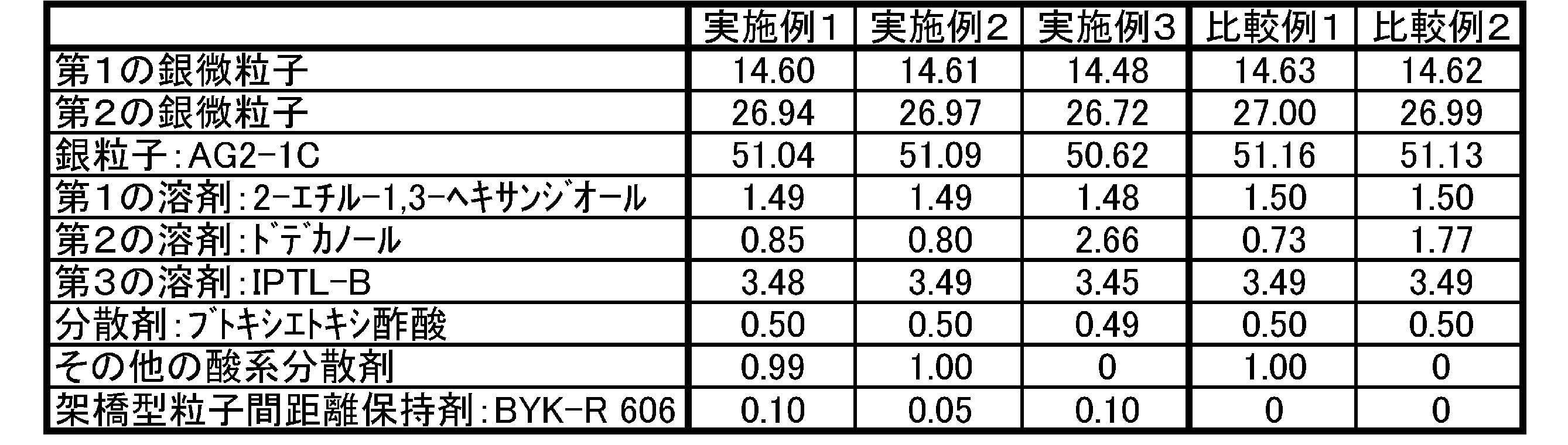
(Preparation of bonding material)
Next, the following were kneaded, and the obtained kneaded material was passed through three rolls to obtain a bonding material made of silver paste.
A dry powder of silver fine particles (coated with hexanoic acid) having a particle diameter of 17 nm prepared as the first silver fine particles, 14.60% by mass
A dry powder of silver fine particles (coated with sorbic acid) having a particle size of 85 nm prepared as the second silver fine particles, 26.94% by mass
・ Silver particles having a particle diameter of 0.6 μm (AG2-1C manufactured by DOWA Electronics) 51.04% by mass
-Octanediol (2-ethyl-1,3-hexanediol manufactured by Wako Pure Chemical Industries, Ltd.) as the first solvent 1.49% by mass
-1-dodecanol (manufactured by Tokyo Chemical Industry Co., Ltd.) 0.85 mass% as the second solvent
2-methyl-butane-1,3,4-triol (isoprenetriol B (IPTL-B)) as a third solvent (made by Nippon Terpene Chemical Co., Ltd.) 3.48% by mass
・ Butoxyethoxyacetic acid (BEA) as a dispersant (manufactured by Tokyo Chemical Industry Co., Ltd.) 0.50% by mass
・ 0.99% by mass of other acid-based dispersants
・ Polyhydroxycarboxylic acid ester (BYK-R606 manufactured by BYK Japan) as a cross-linking interparticle distance retention agent, 0.10% by mass
The above components and contents are summarized in Table 1 below. In addition, Table 1 summarizes the constituent components and contents according to Examples 2 to 3 and Comparative Examples 1 and 2 described later.
次に、以下のものを混錬し、得られた混練物を三本ロールを通過させて、銀ペーストからなる接合材を得た。
・第1の銀微粒子として上記で作製した、粒径17nmの(ヘキサン酸で被覆された)銀微粒子の乾燥粉末14.60質量%
・第2の銀微粒子として上記で作製した、粒径85nmの(ソルビン酸で被覆された)銀微粒子の乾燥粉末26.94質量%
・粒径0.6μmの銀粒子(DOWAエレクトロニクス社製のAG2-1C)51.04質量%
・第1の溶剤としてのオクタンジオール(和光純薬工業株式会社製の2-エチル-1,3-ヘキサンジオール)1.49質量%
・第2の溶剤としての1-ドデカノール(東京化成工業株式会社製)0.85質量%
・第3の溶剤としての2-メチル-ブタン-1,3,4-トリオール(イソプレントリオールB(IPTL-B))(日本テルペン化学株式会社製)3.48質量%
・分散剤としてのブトキシエトキシ酢酸(BEA)(東京化成工業株式会社製)0.50質量%
・その他の酸系分散剤0.99質量%
・架橋型粒子間距離保持剤としてのポリヒドロキシカルボン酸エステル(ビックケミー・ジャパン社製のBYK-R606)0.10質量%
上記の各構成成分及び含有量については以下の表1にまとめた。また、後述の実施例2~3、比較例1~2に係る各構成成分及び含有量についても表1にまとめた。
Next, the following were kneaded, and the obtained kneaded material was passed through three rolls to obtain a bonding material made of silver paste.
A dry powder of silver fine particles (coated with hexanoic acid) having a particle diameter of 17 nm prepared as the first silver fine particles, 14.60% by mass
A dry powder of silver fine particles (coated with sorbic acid) having a particle size of 85 nm prepared as the second silver fine particles, 26.94% by mass
・ Silver particles having a particle diameter of 0.6 μm (AG2-1C manufactured by DOWA Electronics) 51.04% by mass
-Octanediol (2-ethyl-1,3-hexanediol manufactured by Wako Pure Chemical Industries, Ltd.) as the first solvent 1.49% by mass
-1-dodecanol (manufactured by Tokyo Chemical Industry Co., Ltd.) 0.85 mass% as the second solvent
2-methyl-butane-1,3,4-triol (isoprenetriol B (IPTL-B)) as a third solvent (made by Nippon Terpene Chemical Co., Ltd.) 3.48% by mass
・ Butoxyethoxyacetic acid (BEA) as a dispersant (manufactured by Tokyo Chemical Industry Co., Ltd.) 0.50% by mass
・ 0.99% by mass of other acid-based dispersants
・ Polyhydroxycarboxylic acid ester (BYK-R606 manufactured by BYK Japan) as a cross-linking interparticle distance retention agent, 0.10% by mass
The above components and contents are summarized in Table 1 below. In addition, Table 1 summarizes the constituent components and contents according to Examples 2 to 3 and Comparative Examples 1 and 2 described later.
(接合材の粘度)
この接合材(銀ペースト)の粘度をレオメーター(回転式動的粘弾性測定装置)(Thermo社製のHAAKE RheoStress 600、コーン径35mm、コーン角度2°のコーンを使用)により求めたところ、25℃において5rpmで24(Pa・s)であった。なお1rpmでの粘度は65(Pa・s)であった。
上記の粘度については以下の表2にまとめた。また、後述の実施例2~3、比較例1~2に係る粘度、及び評価結果(詳細は後述)についても表2にまとめている。
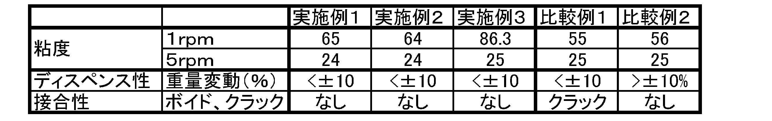
(Viscosity of bonding material)
When the viscosity of this bonding material (silver paste) was determined by a rheometer (rotary dynamic viscoelasticity measuring device) (HAAKE Rheo Stress 600 manufactured by Thermo, cone having a cone diameter of 35 mm and cone angle of 2 ° was used), 25 It was 24 (Pa · s) at 5 rpm at ° C. The viscosity at 1 rpm was 65 (Pa · s).
The above viscosities are summarized in Table 2 below. Table 2 also summarizes the viscosities and evaluation results (details will be described later) according to Examples 2 to 3 and Comparative Examples 1 and 2 described later.
この接合材(銀ペースト)の粘度をレオメーター(回転式動的粘弾性測定装置)(Thermo社製のHAAKE RheoStress 600、コーン径35mm、コーン角度2°のコーンを使用)により求めたところ、25℃において5rpmで24(Pa・s)であった。なお1rpmでの粘度は65(Pa・s)であった。
上記の粘度については以下の表2にまとめた。また、後述の実施例2~3、比較例1~2に係る粘度、及び評価結果(詳細は後述)についても表2にまとめている。
When the viscosity of this bonding material (silver paste) was determined by a rheometer (rotary dynamic viscoelasticity measuring device) (
The above viscosities are summarized in Table 2 below. Table 2 also summarizes the viscosities and evaluation results (details will be described later) according to Examples 2 to 3 and Comparative Examples 1 and 2 described later.
[実施例2]
接合材(銀ペースト)中の各構成成分の配合量を上記表1に示す通り変更した(粘度がおおよそ同等になるように各成分の配合量を調整している。以下同様)以外は、実施例1と同様の方法により、接合材を作製した。そして接合材の粘度を求めたところ、25℃において1rpmで64(Pa・s)、5rpmで24(Pa・s)であった。 [Example 2]
Except for changing the blending amount of each component in the bonding material (silver paste) as shown in Table 1 above (the blending amount of each component is adjusted so that the viscosity is approximately the same. The same applies hereinafter) A bonding material was produced in the same manner as in Example 1. When the viscosity of the bonding material was determined, it was 64 (Pa · s) at 1 rpm at 25 ° C. and 24 (Pa · s) at 5 rpm.
[実施例3]
接合材(銀ペースト)中の各構成成分の配合量を上記表1に示す通り変更した以外は、実施例1と同様の方法により、接合材を作製した。そして接合材の粘度を求めたところ、25℃において1rpmで86.3(Pa・s)、5rpmで25(Pa・s)であった。 [Example 3]
A bonding material was produced in the same manner as in Example 1 except that the amount of each constituent component in the bonding material (silver paste) was changed as shown in Table 1 above. When the viscosity of the bonding material was determined, it was 86.3 (Pa · s) at 1 rpm at 25 ° C. and 25 (Pa · s) at 5 rpm.
[比較例1]
接合材(銀ペースト)中の架橋型粒子間距離保持剤としてポリヒドロキシカルボン酸エステル(ビックケミー・ジャパン社製のBYK-R606)を使用せず、各構成成分の配合量を上記表1に示す通り変更した以外は、実施例1と同様の方法により、接合材を作製した。そして接合材の粘度を求めたところ、25℃において1rpmで55(Pa・s)、5rpmで25(Pa・s)であった。 [Comparative Example 1]
As shown in Table 1 above, the polyhydroxycarboxylic acid ester (BYK-R606 manufactured by Big Chemie Japan) is not used as a cross-linking interparticle distance retention agent in the bonding material (silver paste), and the amount of each component is as shown in Table 1 above. A bonding material was produced in the same manner as in Example 1 except that the change was made. When the viscosity of the bonding material was determined, it was 55 (Pa · s) at 1 rpm at 25 ° C. and 25 (Pa · s) at 5 rpm.
[比較例2]
接合材(銀ペースト)中の架橋型粒子間距離保持剤としてポリヒドロキシカルボン酸エステル(ビックケミー・ジャパン社製のBYK-R606)を使用せず、且つ、分散剤をブトキシエトキシ酢酸(BEA)(東京化成工業株式会社製)のみとし、各構成成分の配合量を上記表1に示す通り変更した以外は、実施例1と同様の方法により、接合材を作製した。そして接合材の粘度を求めたところ、25℃において1rpmで56(Pa・s)、5rpmで25(Pa・s)であった。 [Comparative Example 2]
No polyhydroxycarboxylic acid ester (BYK-R606 manufactured by BYK Japan) was used as a cross-linking interparticle distance-retaining agent in the bonding material (silver paste), and the dispersant was butoxyethoxyacetic acid (BEA) (Tokyo) A bonding material was produced in the same manner as in Example 1 except that the amount of each component was changed as shown in Table 1 above. When the viscosity of the bonding material was determined, it was 56 (Pa · s) at 1 rpm at 25 ° C. and 25 (Pa · s) at 5 rpm.
[評価]
(ディスペンス性の評価)
以上の実施例及び比較例で得られた接合材を用いてディスペンス性の評価を行った。ディスペンス性の評価方法としては、以下のものを採用した。 [Evaluation]
(Evaluation of dispensing properties)
Dispensability was evaluated using the bonding materials obtained in the above Examples and Comparative Examples. As a method for evaluating the dispensing property, the following was adopted.
シリンジに上記の接合材(銀ペースト)を充填した。シリンジのニードルとして0.58mmφのものを取り付け、23mm長さのラインパターンを武蔵エンジニアリング製のディスペンサー(ML-5000XII)を使用して描画(印刷)した。
The syringe was filled with the above bonding material (silver paste). A syringe needle of 0.58 mmφ was attached, and a 23 mm long line pattern was drawn (printed) using a dispenser (ML-5000XII) manufactured by Musashi Engineering.
手順としては、まず、ガラス板に対して、このラインパターンを1個印刷した(いわゆる捨て打ち)。そして3分間印刷を停止した後、別のガラス板に対してラインパターンを10個印刷した。一つのラインパターンを印刷し終えてから次のラインパターンを印刷し始めるまでの間隔は1秒であった。
As a procedure, first, one line pattern was printed on a glass plate (so-called discarding). And after stopping printing for 3 minutes, ten line patterns were printed with respect to another glass plate. The interval from printing one line pattern to starting printing the next line pattern was 1 second.
その後、更に別のガラス板に対してラインパターンを10個印刷した。なお、前のガラス板に最後のラインパターンを印刷し終えてから次のガラス板に最初のラインパターンを印刷し始めるまでの間隔は2秒であった。このようにして、ラインパターンを10個印刷したガラス板を15枚用意した。
Thereafter, 10 line patterns were printed on another glass plate. Note that the interval from the end of printing the last line pattern on the previous glass plate to the start of printing the first line pattern on the next glass plate was 2 seconds. In this way, 15 glass plates on which 10 line patterns were printed were prepared.
以上ラインパターンを印刷したガラス板について、1枚目のガラス板の10パターンの重量を100%としたとき、他の2~15枚目のガラス板の各10パターンの重量がどの程度変動しているかを求めた。その結果、実施例1~3及び比較例1については±10%以内のばらつきに収まっていたが、比較例2については重量変動が±10%を超えていた。
ちなみに、比較例1においてはディスペンス性は悪くない結果であったが、実施例1と比較例1との間には、別の評価項目である接合性にて大きな相違が生じることになる。 Regarding the glass plate on which the line pattern is printed as described above, when the weight of 10 patterns of the first glass plate is 100%, how much the weight of each 10 pattern of the other 2 to 15th glass plates varies. I asked. As a result, in Examples 1 to 3 and Comparative Example 1, the variation was within ± 10%, but in Comparative Example 2, the weight fluctuation exceeded ± 10%.
Incidentally, although the dispensing property was not bad in Comparative Example 1, there was a great difference between Example 1 and Comparative Example 1 in the bonding property, which is another evaluation item.
(接合性の評価)
次に接合試験を実施した。基板としては10mm角の銅板に金めっきをしたものを用いた。この銅板に対してディスペンサー(ML-5000XII)によって各実施例及び比較例の接合材(銀ペースト)を3mm角相当のスノースター(米印)形状に塗布し、その上に、3mm角の金めっきが施された半導体素子をマウントした。その後、圧力を加えない状態で、銅板、半導体素子、その間に存在する接合材を、イナートオーブンで0.05℃/秒で210℃まで昇温してから60分間維持し、銀微粒子及び銀粒子を焼結させ、銀接合層を形成した。こうして得られた接合体について、超音波探傷検査装置(C-SAM:SONOSCAN社製のD9500)により得られた画像(C-SAM像)から、銀接合層(の内部と銀接合層と基板及びSiチップとのそれぞれの界面)のボイドの有無を観察した。 (Evaluation of bondability)
Next, a joining test was performed. As the substrate, a 10 mm square copper plate plated with gold was used. The bonding material (silver paste) of each example and comparative example was applied to this copper plate in a snow star (US mark) shape corresponding to a 3 mm square by a dispenser (ML-5000XII), and then a 3 mm square gold plating was applied thereon. The semiconductor element to which was applied was mounted. Thereafter, in a state where no pressure is applied, the copper plate, the semiconductor element, and the bonding material existing between them are heated to 210 ° C. at 0.05 ° C./second in an inert oven and maintained for 60 minutes. Was sintered to form a silver bonding layer. From the image (C-SAM image) obtained by the ultrasonic flaw detection inspection apparatus (C-SAM: DONA500 manufactured by SONOSCAN) for the bonded body thus obtained, the silver bonded layer (inside, the silver bonded layer and the substrate, and The presence or absence of voids at each interface with the Si chip was observed.
代表例として実施例1及び比較例1の結果を図1に示す。図1の(a)は実施例1の接合材を使用した銀接合層についての観察結果、(b)は比較例1の接合材を使用した銀接合層についての観察結果を示す。
なお、C-SAM像の全面が黒い場合は、ボイドがなく、良好に接合されていると判断し、C-SAM像に白い部分がある場合は、ボイドやクラックがあり、接合状態が良好でないと判断した。 As a representative example, the results of Example 1 and Comparative Example 1 are shown in FIG. (A) of FIG. 1 shows the observation result about the silver bonding layer using the bonding material of Example 1, and (b) shows the observation result about the silver bonding layer using the bonding material of Comparative Example 1.
In addition, when the entire surface of the C-SAM image is black, it is determined that there is no void and is well bonded. When the white portion is present in the C-SAM image, there are voids and cracks, and the bonding state is not good. It was judged.
接合性評価の結果、実施例1~3及び比較例2の接合材を使用した場合においては、クラックやボイドは確認されず良好に接合が行われていた。その一方、比較例1の接合材を使用した場合には、図1(b)に示す通りクラックが発生しており、接合は良好でなかった。
以上から、実施例1~3ならばディスペンス性と接合性が共に良好な接合材及びそれを用いた接合方法を提供することができていた。 As a result of the bondability evaluation, when the bonding materials of Examples 1 to 3 and Comparative Example 2 were used, cracks and voids were not confirmed and bonding was performed satisfactorily. On the other hand, when the bonding material of Comparative Example 1 was used, cracks occurred as shown in FIG. 1B, and the bonding was not good.
From the above, in Examples 1 to 3, it was possible to provide a bonding material having good dispensing properties and bonding properties and a bonding method using the same.
[各実施例において粘度が速やかに回復していることの実証]
以上の通り、各実施例においてはディスペンス性及び接合特性が良好であった。ところで、本発明の実施の形態の項目にて、この結果をもたらしている理由として、接合材において、せん断の力が加えられなくなった時の粘度の回復が速やかに行われるという効果をもたらすことについて述べた。本項目では、代表例として実施例1及び比較例2についてせん断の力の有無及びその時間経過により粘度がどの程度速やかに回復するかについて実証する。 [Demonstration that viscosity is quickly recovered in each example]
As described above, in each example, the dispensing property and the bonding property were good. By the way, in the item of the embodiment of the present invention, the reason why this result is brought about is that the bonding material has an effect that the viscosity is restored quickly when the shearing force is not applied. Stated. In this item, as a representative example, for Example 1 and Comparative Example 2, the presence or absence of shearing force and how quickly the viscosity recovers with the passage of time will be demonstrated.
まず、実施例1及び比較例2にて作製した接合材の粘度を、上記のレオメーター(回転式動的粘弾性測定装置)(Thermo社製のHAAKE RheoStress 600)を用いて経時的に測定した。具体的には、接合材の温度を25℃とし、シアレート10(1/s)にて120秒測定し、その後シアレート1(1/s)へと減少させて600秒測定した。この時、シアレート1(1/s)へと減少させてから各時点での粘度を、測定終了時(シアレートを1(1/s)へと減少させたまま600秒経過した時)の粘度で除した値を回復率とした。これらの結果を示すのが図2~5である。
First, the viscosity of the bonding material produced in Example 1 and Comparative Example 2 was measured over time using the above rheometer (rotary dynamic viscoelasticity measuring device) (HAAKE RheoStress 600 manufactured by Thermo). . Specifically, the temperature of the bonding material was set to 25 ° C., and the measurement was performed at a shear rate of 10 (1 / s) for 120 seconds, and then decreased to a shear rate of 1 (1 / s) and measured for 600 seconds. At this time, the viscosity at each time point after decreasing to shear rate 1 (1 / s) is the viscosity at the end of measurement (when 600 seconds have passed with the shear rate decreased to 1 (1 / s)). The value divided was taken as the recovery rate. These results are shown in FIGS.
図2は、実施例1に係る接合材に対してせん断強度(シアレート:1/s)を変化させた際の粘度の経時的な変化の結果を示すプロットであり、横軸は時間(s)、縦軸は粘度(Pa・s)を示す。図3は、図2から求めた回復率の経時的な変化の結果を示すプロットであり、横軸は時間(s)、縦軸は回復率を示す。なお、図3の0秒は図2の120秒時点に対応する。
その一方、図4は、比較例2に係る接合材に対してせん断強度(シアレート:1/s)を変化させた際の粘度の経時的な変化の結果を示すプロットであり、横軸は時間(s)、縦軸は粘度(Pa・s)を示す。図5は、図4から求めた回復率の経時的な変化の結果を示すプロットであり、横軸は時間(s)、縦軸は回復率を示す。なお、図5の0秒は図4の120秒時点に対応する。 FIG. 2 is a plot showing the results of changes in viscosity over time when the shear strength (shear rate: 1 / s) was changed for the bonding material according to Example 1, and the horizontal axis represents time (s). The vertical axis indicates the viscosity (Pa · s). FIG. 3 is a plot showing the results of change over time in the recovery rate obtained from FIG. 2, where the horizontal axis indicates time (s) and the vertical axis indicates the recovery rate. Note that 0 second in FIG. 3 corresponds to 120 seconds in FIG.
On the other hand, FIG. 4 is a plot showing the results of changes in viscosity over time when the shear strength (shear rate: 1 / s) was changed for the bonding material according to Comparative Example 2, and the horizontal axis represents time. (S), vertical axis indicates viscosity (Pa · s). FIG. 5 is a plot showing the results of the change over time in the recovery rate obtained from FIG. 4. The horizontal axis represents time (s) and the vertical axis represents the recovery rate. Note that 0 second in FIG. 5 corresponds to 120 seconds in FIG.
実施例1(図2)においては、シアレートを一気に1(1/s)へと減少させた後、極めて速やかに粘度が回復している。それを示すがごとく、図3においては測定開始時点の回復率が0.90以上となっている。
その一方、比較例2(図4)においては、粘度の回復の速度は極めて緩慢である。それを示すがごとく、図5においては回復率が例えば0.90となるだけでも相当の時間を要する。この回復の緩慢さが、吐出量の変動に繋がり、最終的にはディスペンス性の課題に繋がっている。
しかしながら各実施例ならば、速やかに粘度を回復させることが可能となり、ディスペンス性のみならず、接合性をも良好にすることが可能となるのである。また、以上の結果からわかるように、接合材における上記規定の回復率は高いことが好ましく、具体的には測定開始時点において0.80以上であるのが好ましく、0.85以上であるのがより好ましい。 In Example 1 (FIG. 2), after the shear rate was reduced to 1 (1 / s) at once, the viscosity recovered very rapidly. As shown, the recovery rate at the start of measurement is 0.90 or more in FIG.
On the other hand, in Comparative Example 2 (FIG. 4), the speed of viscosity recovery is extremely slow. As shown in FIG. 5, it takes a considerable time even if the recovery rate is 0.90, for example. This slow recovery leads to fluctuations in the discharge amount, which ultimately leads to dispensing problems.
However, in each example, the viscosity can be quickly recovered, and not only the dispensing property but also the bonding property can be improved. Further, as can be seen from the above results, the specified recovery rate in the bonding material is preferably high, specifically, preferably 0.80 or more at the start of measurement, and 0.85 or more. More preferred.
[実施例4~7]
実施例4~7においては、実施例1~3にて架橋型粒子間距離保持剤として使用したBYK-R606の代わりに、ヒノアクトKF-1000(実施例4)、MA-WAX-O(実施例5)、ツノダイム395(実施例6)、ヒマ硬(実施例7)を使用して試験を行った。なお、第1の銀微粒子及び第2の銀微粒子の作製手法は実施例1の通りとし、その他、特記の無い事項は実施例1に記載された通りとする。 [Examples 4 to 7]
In Examples 4 to 7, Hinoact KF-1000 (Example 4) and MA-WAX-O (Examples) were used instead of BYK-R606 used as a cross-linking interparticle distance retaining agent in Examples 1 to 3. 5), Tsunodim 395 (Example 6) and castor hard (Example 7) were used for the test. The method for producing the first silver fine particles and the second silver fine particles is as described in Example 1, and other matters not specifically mentioned are as described in Example 1.
(接合材の作製)
次に、以下のものを混錬し、得られた混練物を三本ロールを通過させて、銀ペーストからなる接合材を得た。
・第1の銀微粒子として上記で作製した、粒径17nmの(ヘキサン酸で被覆された)銀微粒子の乾燥粉末14.61質量%
・第2の銀微粒子として上記で作製した、粒径85nmの(ソルビン酸で被覆された)銀微粒子の乾燥粉末26.97質量%
・粒径0.6μmの銀粒子(DOWAエレクトロニクス社製のAG2-1C)51.09質量%
・第1の溶剤としてのオクタンジオール(和光純薬工業株式会社製の2-エチル-1,3-ヘキサンジオール)1.49質量%
・第2の溶剤としての1-ドデカノール(東京化成工業株式会社製)0.80質量%
・第3の溶剤としての2-メチル-ブタン-1,3,4-トリオール(イソプレントリオールB(IPTL-B))(日本テルペン化学株式会社製)3.49質量%
・分散剤としてのブトキシエトキシ酢酸(BEA)(東京化成工業株式会社製)0.50質量%
・その他の酸系分散剤1.00質量%
・実施例4~7に応じた架橋型粒子間距離保持剤0.05質量%
上記の各構成成分及び含有量については以下の表3にまとめた。また、後述の各例に係る各構成成分及び含有量についても表3にまとめた。
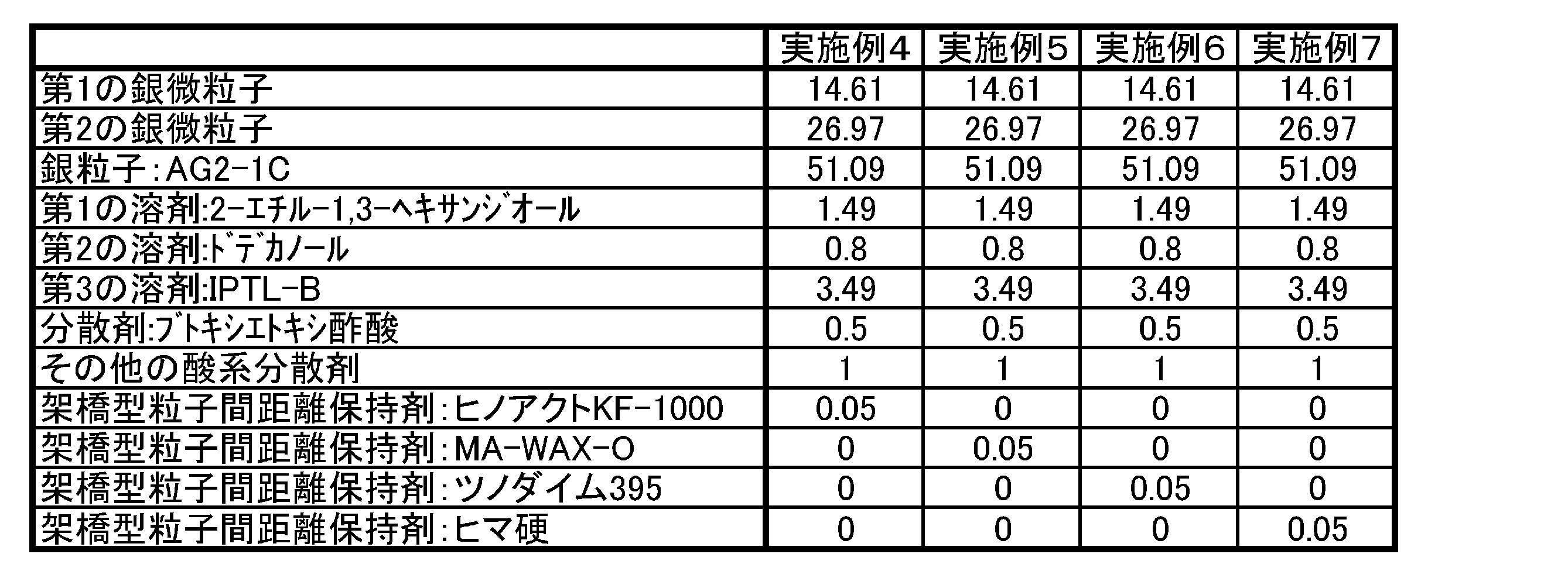
(Preparation of bonding material)
Next, the following were kneaded, and the obtained kneaded material was passed through three rolls to obtain a bonding material made of silver paste.
A dry powder of 14.61% by mass of silver fine particles (coated with hexanoic acid) having a particle diameter of 17 nm prepared as the first silver fine particles.
A dry powder of silver fine particles (coated with sorbic acid) having a particle diameter of 85 nm prepared as the second silver fine particles, 26.97% by mass
・ Silver particles having a particle diameter of 0.6 μm (AG2-1C manufactured by DOWA Electronics) 51.09% by mass
-Octanediol (2-ethyl-1,3-hexanediol manufactured by Wako Pure Chemical Industries, Ltd.) as the first solvent 1.49% by mass
-1-dodecanol (manufactured by Tokyo Chemical Industry Co., Ltd.) 0.80% by mass as the second solvent
2-methyl-butane-1,3,4-triol (isoprenetriol B (IPTL-B)) (made by Nippon Terpene Chemical Co., Ltd.) as a third solvent 3.49% by mass
・ Butoxyethoxyacetic acid (BEA) as a dispersant (manufactured by Tokyo Chemical Industry Co., Ltd.) 0.50% by mass
・ Other acid dispersant 1.00% by mass
-0.05% by mass of a cross-link type interparticle distance retaining agent according to Examples 4 to 7
The above components and contents are summarized in Table 3 below. In addition, Table 3 also summarizes each constituent component and content according to each example described later.
次に、以下のものを混錬し、得られた混練物を三本ロールを通過させて、銀ペーストからなる接合材を得た。
・第1の銀微粒子として上記で作製した、粒径17nmの(ヘキサン酸で被覆された)銀微粒子の乾燥粉末14.61質量%
・第2の銀微粒子として上記で作製した、粒径85nmの(ソルビン酸で被覆された)銀微粒子の乾燥粉末26.97質量%
・粒径0.6μmの銀粒子(DOWAエレクトロニクス社製のAG2-1C)51.09質量%
・第1の溶剤としてのオクタンジオール(和光純薬工業株式会社製の2-エチル-1,3-ヘキサンジオール)1.49質量%
・第2の溶剤としての1-ドデカノール(東京化成工業株式会社製)0.80質量%
・第3の溶剤としての2-メチル-ブタン-1,3,4-トリオール(イソプレントリオールB(IPTL-B))(日本テルペン化学株式会社製)3.49質量%
・分散剤としてのブトキシエトキシ酢酸(BEA)(東京化成工業株式会社製)0.50質量%
・その他の酸系分散剤1.00質量%
・実施例4~7に応じた架橋型粒子間距離保持剤0.05質量%
上記の各構成成分及び含有量については以下の表3にまとめた。また、後述の各例に係る各構成成分及び含有量についても表3にまとめた。
Next, the following were kneaded, and the obtained kneaded material was passed through three rolls to obtain a bonding material made of silver paste.
A dry powder of 14.61% by mass of silver fine particles (coated with hexanoic acid) having a particle diameter of 17 nm prepared as the first silver fine particles.
A dry powder of silver fine particles (coated with sorbic acid) having a particle diameter of 85 nm prepared as the second silver fine particles, 26.97% by mass
・ Silver particles having a particle diameter of 0.6 μm (AG2-1C manufactured by DOWA Electronics) 51.09% by mass
-Octanediol (2-ethyl-1,3-hexanediol manufactured by Wako Pure Chemical Industries, Ltd.) as the first solvent 1.49% by mass
-1-dodecanol (manufactured by Tokyo Chemical Industry Co., Ltd.) 0.80% by mass as the second solvent
2-methyl-butane-1,3,4-triol (isoprenetriol B (IPTL-B)) (made by Nippon Terpene Chemical Co., Ltd.) as a third solvent 3.49% by mass
・ Butoxyethoxyacetic acid (BEA) as a dispersant (manufactured by Tokyo Chemical Industry Co., Ltd.) 0.50% by mass
・ Other acid dispersant 1.00% by mass
-0.05% by mass of a cross-link type interparticle distance retaining agent according to Examples 4 to 7
The above components and contents are summarized in Table 3 below. In addition, Table 3 also summarizes each constituent component and content according to each example described later.
(接合材の粘度)
この接合材(銀ペースト)の25℃における粘度をレオメーター(回転式動的粘弾性測定装置)(Thermo社製のHAAKE RheoStress 600、コーン径35mm、コーン角度2°のコーンを使用)により求めた。前記の粘度及びチキソトロピー性(Ti=粘度(1rpm)/粘度(5rpm))については以下の表4にまとめた。また、後述の各例に係る粘度及びTiについても表4にまとめている。
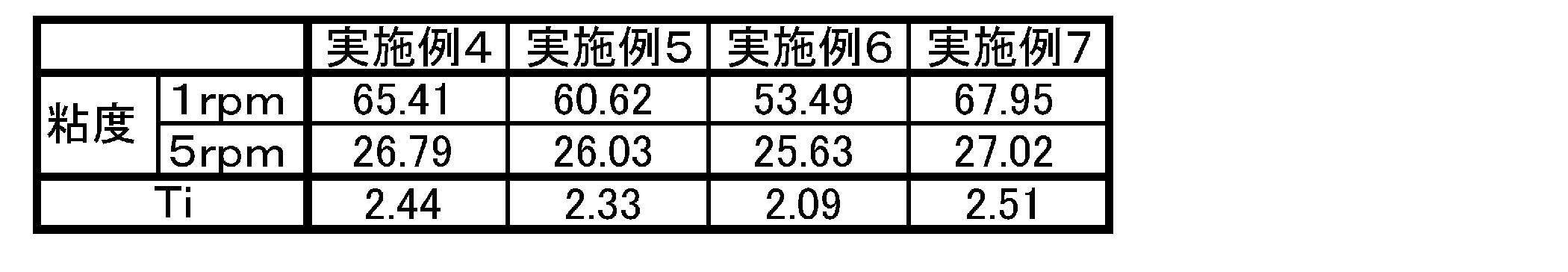
(Viscosity of bonding material)
The viscosity of this bonding material (silver paste) at 25 ° C. was determined with a rheometer (rotary dynamic viscoelasticity measuring device) (HAAKE Rheo Stress 600 manufactured by Thermo, cone diameter 35 mm, cone having a cone angle of 2 ° was used). . The viscosity and thixotropic properties (Ti = viscosity (1 rpm) / viscosity (5 rpm)) are summarized in Table 4 below. Table 4 also summarizes viscosity and Ti according to each example described later.
この接合材(銀ペースト)の25℃における粘度をレオメーター(回転式動的粘弾性測定装置)(Thermo社製のHAAKE RheoStress 600、コーン径35mm、コーン角度2°のコーンを使用)により求めた。前記の粘度及びチキソトロピー性(Ti=粘度(1rpm)/粘度(5rpm))については以下の表4にまとめた。また、後述の各例に係る粘度及びTiについても表4にまとめている。
The viscosity of this bonding material (silver paste) at 25 ° C. was determined with a rheometer (rotary dynamic viscoelasticity measuring device) (
[評価]
(ディスペンス性の評価)
上述の通り、接合材のディスペンス性が良好であることの理由として、接合材において、せん断の力が加えられなくなった時の粘度の回復が速やかに行われることがある。そのため、実施例4~7においては、粘度が速やかに回復していることをもって、ディスペンス性の評価とした。具体的には、先の[各実施例において粘度が速やかに回復していることの実証]にて用いた手法を採用して測定を行った。実施例4~7における結果を示すのが図6~13である。 [Evaluation]
(Evaluation of dispensing properties)
As described above, the reason why the bonding material has good dispensing property is that the viscosity of the bonding material can be quickly recovered when shearing force is no longer applied. Therefore, in Examples 4 to 7, the dispensing property was evaluated because the viscosity was rapidly recovered. Specifically, the measurement was carried out by employing the method used in the previous [Proof of Viscosity Recovering Immediately in Each Example]. The results in Examples 4 to 7 are shown in FIGS.
図6は、実施例4(ヒノアクトKF-1000)に係る接合材に対してせん断強度(シアレート:1/s)を変化させた際の粘度の経時的な変化の結果を示すプロットであり、横軸は時間(s)、縦軸は粘度(Pa・s)を示す。図7は、図6から求めた回復率の経時的な変化の結果を示すプロットであり、横軸は時間(s)、縦軸は回復率を示す。なお、図7の0秒は図6の120秒時点に対応する。
FIG. 6 is a plot showing the results of changes in viscosity over time when the shear strength (shear rate: 1 / s) was changed for the bonding material according to Example 4 (Hinoact KF-1000). The axis represents time (s), and the vertical axis represents viscosity (Pa · s). FIG. 7 is a plot showing the results of the change over time in the recovery rate obtained from FIG. 6, with the horizontal axis indicating time (s) and the vertical axis indicating the recovery rate. Note that 0 second in FIG. 7 corresponds to 120 seconds in FIG.
実施例4に係る結果が図6,7に対応するのと同様に、実施例5(MA-WAX-O)に係る結果は図8,9に対応し、実施例6(ツノダイム395)に係る結果は図10,11に対応し、実施例7(ヒマ硬)に係る結果は図12,13に対応する。
Just as the results according to Example 4 correspond to FIGS. 6 and 7, the results according to Example 5 (MA-WAX-O) correspond to FIGS. 8 and 9, and according to Example 6 (Tsunodaim 395). The results correspond to FIGS. 10 and 11, and the results according to Example 7 (castor hard) correspond to FIGS.
いずれの実施例においても、比較例2に比べ、シアレートを一気に1(1/s)へと減少させた後、速やかに粘度が回復していた。それを示すがごとく、いずれの実施例においても、測定開始時点の回復率が0.78以上となっている。なお、実施例6及び7は、実施例4及び5(そして実施例1)と比べると粘度回復の速度が遅く(例えば粘度の回復率が0.95になるまでの時間が長い)、ディスペンス性の点では実施例4及び5の接合材の方が優れている。
In any of the Examples, compared with Comparative Example 2, the viscosity was quickly recovered after the shear rate was reduced to 1 (1 / s) at once. As shown, the recovery rate at the start of measurement is 0.78 or more in any of the examples. In Examples 6 and 7, the speed of viscosity recovery is slower than that of Examples 4 and 5 (and Example 1) (for example, the time until the viscosity recovery rate becomes 0.95 is long), and the dispensing property is high. In this respect, the bonding materials of Examples 4 and 5 are superior.
それに加え、実施例4~7のうち、実施例4(ヒノアクトKF-1000)及び実施例5(MA-WAX-O)においては特に、粘度が速やかに回復した。
In addition, in Examples 4 to 7, in Example 4 (Hinoact KF-1000) and Example 5 (MA-WAX-O), the viscosity recovered rapidly.
(接合性の評価)
次に、先の実施例1~3、比較例1~2と同様の手法で接合試験を実施した。 (Evaluation of bondability)
Next, a joining test was performed in the same manner as in Examples 1 to 3 and Comparative Examples 1 and 2.
次に、先の実施例1~3、比較例1~2と同様の手法で接合試験を実施した。 (Evaluation of bondability)
Next, a joining test was performed in the same manner as in Examples 1 to 3 and Comparative Examples 1 and 2.
接合性評価の結果、実施例4~7の接合材を使用した場合においては、良好に接合が行われていたが、実施例1~3の場合と比較すると、わずかながらボイドやクラックが確認された。
As a result of the bondability evaluation, when the bonding materials of Examples 4 to 7 were used, the bonding was performed satisfactorily, but a slight amount of voids and cracks were confirmed as compared with the cases of Examples 1 to 3. It was.
以上から、実施例4~7ならばディスペンス性と接合性が共に良好な接合材及びそれを用いた接合方法を提供することができていた。なお、これらの中でディスペンス性に差があること、実施例1~3と比較すると若干接合性に劣ることは上述の通りである。
From the above, in Examples 4 to 7, it was possible to provide a bonding material having good dispensing properties and bonding properties and a bonding method using the same. Among these, as described above, there is a difference in dispensing property, and slightly inferior in bonding property compared with Examples 1 to 3.
[まとめ]
以上の結果からわかるように、各実施例の接合材ではいずれも、架橋型粒子間距離保持剤が添加されており、ディスペンス性及び接合特性が良好であった。
一方、架橋型粒子間距離保持剤が添加されていない比較例1~2では、ディスペンサーにおける吐出量の重量変動が±10%を超えてディスペンス性が悪い結果となるか、または、クラックやボイドが発生して接合性が悪い結果となった。 [Summary]
As can be seen from the above results, in each of the bonding materials of each Example, a cross-linking interparticle distance retention agent was added, and the dispensing properties and bonding characteristics were good.
On the other hand, in Comparative Examples 1 and 2 in which the cross-link type interparticle distance retention agent is not added, the weight fluctuation of the discharge amount in the dispenser exceeds ± 10%, resulting in poor dispensing properties, or cracks and voids. This resulted in poor bondability.
Claims (11)
- 平均一次粒子径が130nm以下である銀微粒子と、
前記銀微粒子間を架橋して前記銀微粒子同士の間隔を保持する架橋型粒子間距離保持剤と、
を含有する、接合材。 Silver fine particles having an average primary particle diameter of 130 nm or less;
A crosslinkable interparticle distance retention agent that crosslinks between the silver fine particles and maintains the spacing between the silver fine particles;
Containing a bonding material. - 前記架橋型粒子間距離保持剤は、下記式(I)で表される化合物αである、請求項1に記載の接合材。
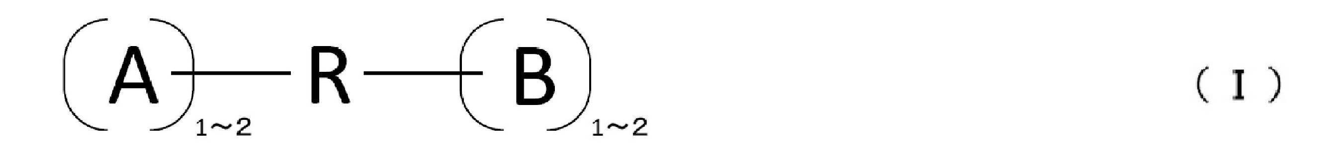
但し、式(I)において、Rは2~4価の有機基であり、
A及びBは、ヒドロキシル基、アミノ基、カルボキシル基又はチオール基であり、Aが2つ存在する場合、それらは互いに同一であっても異なっていてもよく、Bが2つ存在する場合、それらは互いに同一であっても異なっていてもよく、
Rを構成する最も長い直鎖部分において、Aと結合する原子1と、Bと結合する原子2との間の部分のうち最長のものを第一主鎖としたとき、前記第一主鎖の鎖構成原子数は10~180である。 The bonding material according to claim 1, wherein the cross-link type interparticle distance holding agent is a compound α represented by the following formula (I).
However, in the formula (I), R is a divalent to tetravalent organic group,
A and B are a hydroxyl group, an amino group, a carboxyl group or a thiol group, and when two A are present, they may be the same or different from each other, and when two B are present, May be the same or different from each other,
In the longest straight chain portion constituting R, the longest of the portions between the atom 1 bonded to A and the atom 2 bonded to B is defined as the first main chain. The number of chain constituent atoms is 10 to 180. - 前記式(I)におけるA及びBのうち少なくとも一つは、ヒドロキシル基、アミノ基又はチオール基であり、
前記式(I)におけるRを構成する最も長い直鎖部分が側鎖を有し、前記側鎖における最も長い直鎖部分の鎖構成原子数は、前記第一主鎖の鎖構成原子数の1/3以下である、請求項2に記載の接合材。 At least one of A and B in the formula (I) is a hydroxyl group, an amino group or a thiol group,
The longest straight chain part constituting R in the formula (I) has a side chain, and the number of chain constituent atoms of the longest straight chain part in the side chain is 1 of the number of chain constituent atoms of the first main chain. The bonding material according to claim 2, which is / 3 or less. - 前記式(I)におけるRを構成する最も長い直鎖部分が側鎖を有し、前記側鎖は炭素数1~12の炭化水素基であり、A及びBは前記側鎖に結合していてもよい、請求項2又は3に記載の接合材。 The longest straight chain portion constituting R in the formula (I) has a side chain, the side chain is a hydrocarbon group having 1 to 12 carbon atoms, and A and B are bonded to the side chain. The bonding material according to claim 2, wherein the bonding material is good.
- 前記式(I)において、前記化合物αを構成する最も長い直鎖部分を第二主鎖としたとき、前記第一主鎖、及び前記第二主鎖の鎖構成原子(鎖末端の原子を除く)が、-CH2-,-CH(Ra)-,-C(Ra)2-,-CX2-,-CX(Ra)-,-CH=,-C(Ra)=,=C=,-CO-,-NH-,-N(Ra)-,-N=,-N(OH)-,-O-,-S-,-SO2-から選ばれる基を形成している、請求項2~4のいずれかに記載の接合材。
但し、Raは、Rを構成する最も長い直鎖部分が有する側鎖であり、Xはハロゲンである。 In the formula (I), when the longest straight chain portion constituting the compound α is the second main chain, the first main chain and the chain constituent atoms of the second main chain (excluding the atoms at the chain end) ) Is —CH 2 —, —CH (R a ) —, —C (R a ) 2 —, —CX 2 —, —CX (R a ) —, —CH═, —C (R a ) =, ═C═, —CO—, —NH—, —N (R a ) —, —N═, —N (OH) —, —O—, —S—, —SO 2 — is formed. The bonding material according to any one of claims 2 to 4, wherein:
However, R a is the side chain having the longest linear portion constituting the R, X is a halogen. - 前記化合物αは、下記式(II)~(IV)のいずれかである、請求項2に記載の接合材。
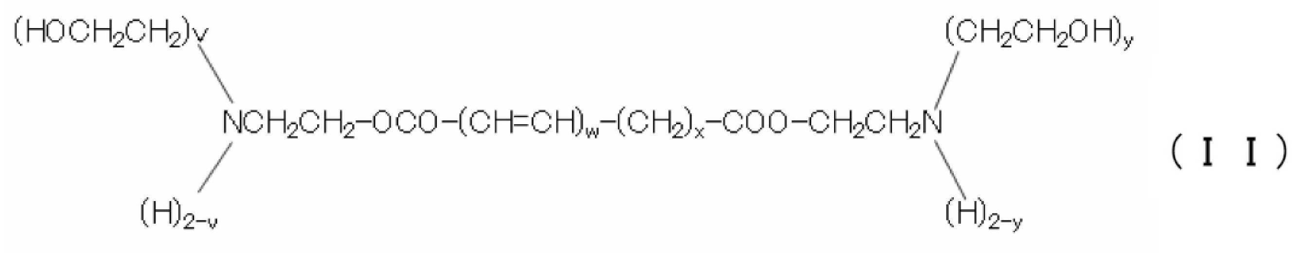
但し、式(II)において、v及びyはそれぞれ独立に1~2の整数であり、wは0~10の整数であり、xは14~40の整数である。
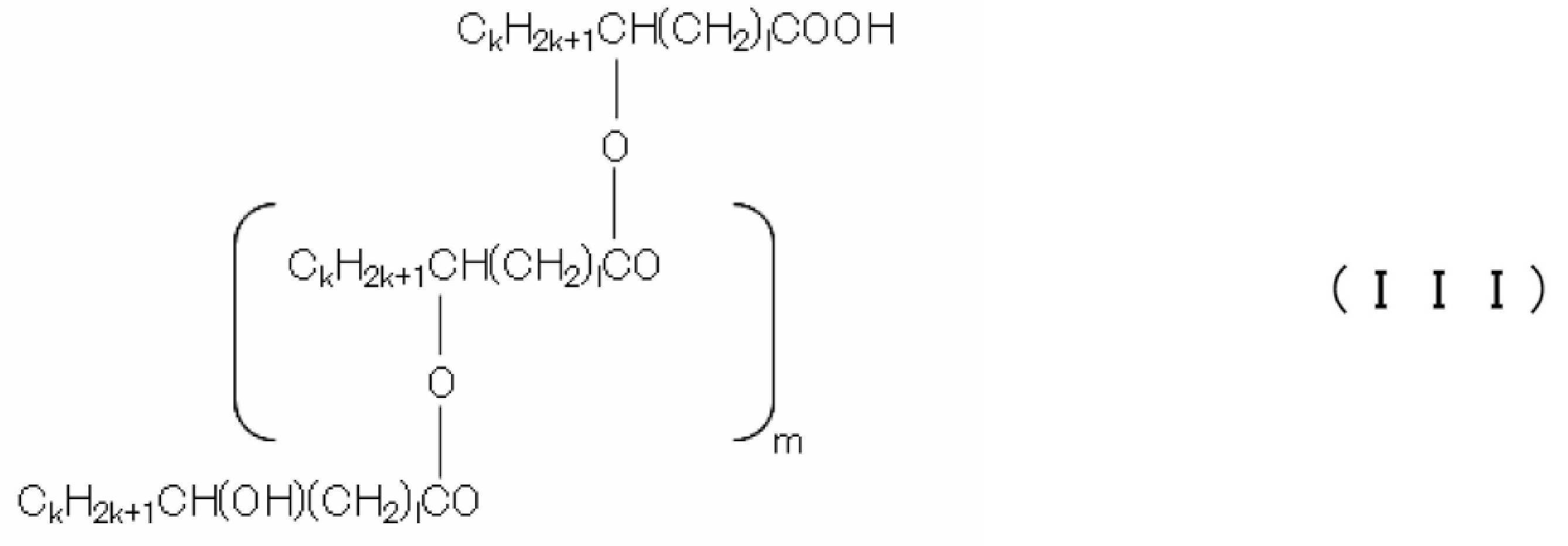
但し、式(III)において、複数存在するkはそれぞれ独立に3~10の整数であり、複数存在するlはそれぞれ独立に6~16の整数であり、mは2~8の整数である。

但し、式(IV)において、n及びsはそれぞれ独立に、3~10の整数であり、p及びrはそれぞれ独立に6~18の整数であり、qは2~10の整数である。 The bonding material according to claim 2, wherein the compound α is any one of the following formulas (II) to (IV).
However, in the formula (II), v and y are each independently an integer of 1 to 2, w is an integer of 0 to 10, and x is an integer of 14 to 40.
However, in the formula (III), a plurality of ks each independently represents an integer of 3 to 10, each of a plurality of ls independently represents an integer of 6 to 16, and m is an integer of 2 to 8.
However, in the formula (IV), n and s are each independently an integer of 3 to 10, p and r are each independently an integer of 6 to 18, and q is an integer of 2 to 10. - 平均一次粒子径が0.3~10μmである銀粒子を更に含有する、請求項1~6のいずれかに記載の接合材。 7. The bonding material according to claim 1, further comprising silver particles having an average primary particle diameter of 0.3 to 10 μm.
- 前記銀微粒子は有機化合物により被覆されている、請求項1~7のいずれかに記載の接合材。 The bonding material according to any one of claims 1 to 7, wherein the silver fine particles are coated with an organic compound.
- 極性溶媒を更に含有する、請求項1~8のいずれかに記載の接合材。 The bonding material according to any one of claims 1 to 8, further comprising a polar solvent.
- 酸系分散剤を更に含有する、請求項1~9のいずれかに記載の接合材。 The bonding material according to any one of claims 1 to 9, further comprising an acid-based dispersant.
- 請求項1~10のいずれかに記載の接合材を被接合物間に介在させて加熱することにより、前記接合材から接合層を形成し、これにより被接合物同士を接合する、接合方法。 A bonding method in which a bonding layer is formed from the bonding material by heating the bonding material according to any one of claims 1 to 10 interposed between the bonding objects, thereby bonding the objects to be bonded together.
Priority Applications (5)
| Application Number | Priority Date | Filing Date | Title |
|---|---|---|---|
| CN201780079148.0A CN110114838A (en) | 2016-12-28 | 2017-12-28 | Grafting material and the joint method for using it |
| EP17886598.6A EP3564969A4 (en) | 2016-12-28 | 2017-12-28 | Bonding material, and bonding method using same |
| US16/473,072 US20200094318A1 (en) | 2016-12-28 | 2017-12-28 | Bonding material and bonding method employing same |
| PCT/JP2017/047171 WO2018124263A1 (en) | 2016-12-28 | 2017-12-28 | Bonding material, and bonding method using same |
| KR1020197017210A KR20190103155A (en) | 2016-12-28 | 2017-12-28 | Bonding material and joining method using the same |
Applications Claiming Priority (5)
| Application Number | Priority Date | Filing Date | Title |
|---|---|---|---|
| JP2016256400 | 2016-12-28 | ||
| JP2016-256400 | 2016-12-28 | ||
| JP2017251767A JP2018109232A (en) | 2016-12-28 | 2017-12-27 | Joint material and joining method using same |
| JP2017-251767 | 2017-12-27 | ||
| PCT/JP2017/047171 WO2018124263A1 (en) | 2016-12-28 | 2017-12-28 | Bonding material, and bonding method using same |
Publications (1)
| Publication Number | Publication Date |
|---|---|
| WO2018124263A1 true WO2018124263A1 (en) | 2018-07-05 |
Family
ID=62709402
Family Applications (1)
| Application Number | Title | Priority Date | Filing Date |
|---|---|---|---|
| PCT/JP2017/047171 WO2018124263A1 (en) | 2016-12-28 | 2017-12-28 | Bonding material, and bonding method using same |
Country Status (7)
| Country | Link |
|---|---|
| US (1) | US20200094318A1 (en) |
| EP (1) | EP3564969A4 (en) |
| JP (1) | JP2018109232A (en) |
| KR (1) | KR20190103155A (en) |
| CN (1) | CN110114838A (en) |
| TW (1) | TW201833247A (en) |
| WO (1) | WO2018124263A1 (en) |
Families Citing this family (3)
| Publication number | Priority date | Publication date | Assignee | Title |
|---|---|---|---|---|
| US10910340B1 (en) * | 2019-10-14 | 2021-02-02 | Heraeus Deutschland GmbH & Co. KG | Silver sintering preparation and the use thereof for the connecting of electronic components |
| JP6836090B1 (en) * | 2020-04-02 | 2021-02-24 | 千住金属工業株式会社 | Flux composition and solder paste using it |
| WO2023248311A1 (en) * | 2022-06-20 | 2023-12-28 | 東洋インキScホールディングス株式会社 | Metal particle-containing composition, paste for bonding and bonded body |
Citations (6)
| Publication number | Priority date | Publication date | Assignee | Title |
|---|---|---|---|---|
| JPS5824201B2 (en) | 1978-03-24 | 1983-05-19 | 株式会社神戸製鋼所 | Surface flaw automatic cutting control method |
| JP2011240406A (en) * | 2010-03-15 | 2011-12-01 | Dowa Electronics Materials Co Ltd | Bonding material and bonding method using the same |
| JP2013218836A (en) * | 2012-04-06 | 2013-10-24 | Ulvac Japan Ltd | Conductive metal paste |
| JP2016000861A (en) * | 2010-11-22 | 2016-01-07 | Dowaエレクトロニクス株式会社 | Joining material and joint body |
| JP2016008332A (en) * | 2014-06-25 | 2016-01-18 | Dowaエレクトロニクス株式会社 | Joining material and joining method using the same |
| JP5976684B2 (en) | 2012-01-20 | 2016-08-24 | Dowaエレクトロニクス株式会社 | Bonding material and bonding method using the same |
Family Cites Families (12)
| Publication number | Priority date | Publication date | Assignee | Title |
|---|---|---|---|---|
| JPS5824201A (en) | 1981-08-06 | 1983-02-14 | Fujitsu Ltd | Helical filter |
| JPS5976684A (en) | 1982-10-22 | 1984-05-01 | Toshiba Corp | Electrode for welding or brazing |
| KR20100085032A (en) * | 2007-09-27 | 2010-07-28 | 바스프 에스이 | Isolable and redispersable transition metal nanoparticles, their preparation and use as ir absorbers |
| JP5398132B2 (en) * | 2007-09-28 | 2014-01-29 | 豊田バンモップス株式会社 | Grinding wheel |
| US8361350B2 (en) * | 2008-12-10 | 2013-01-29 | Xerox Corporation | Silver nanoparticle ink composition |
| WO2011007402A1 (en) * | 2009-07-14 | 2011-01-20 | Dowaエレクトロニクス株式会社 | Bonding material and bonding method each using metal nanoparticles |
| US9137902B2 (en) * | 2009-08-14 | 2015-09-15 | Xerox Corporation | Process to form highly conductive feature from silver nanoparticles with reduced processing temperature |
| JP2013518438A (en) * | 2010-01-25 | 2013-05-20 | ボード オブ トラスティーズ オブ ザ レランド スタンフォード ジュニア ユニバーシティ | Connected nanostructures and methods therefor |
| CN103608140B (en) * | 2011-06-10 | 2016-03-30 | 同和电子科技有限公司 | Grafting material and the conjugant using this grafting material to make |
| JP2013151753A (en) * | 2013-03-04 | 2013-08-08 | Dowa Electronics Materials Co Ltd | Silver micropowder excellent in affinity for polar medium, and silver ink |
| JP6099472B2 (en) * | 2013-04-26 | 2017-03-22 | Dowaエレクトロニクス株式会社 | Metal nanoparticle dispersion, method for producing metal nanoparticle dispersion, and bonding method |
| CN106133894B (en) * | 2014-04-04 | 2018-11-16 | 京瓷株式会社 | Hot curing resin composition, semiconductor device and electrical and electronic parts |
-
2017
- 2017-12-27 JP JP2017251767A patent/JP2018109232A/en active Pending
- 2017-12-28 CN CN201780079148.0A patent/CN110114838A/en active Pending
- 2017-12-28 WO PCT/JP2017/047171 patent/WO2018124263A1/en unknown
- 2017-12-28 KR KR1020197017210A patent/KR20190103155A/en active IP Right Grant
- 2017-12-28 EP EP17886598.6A patent/EP3564969A4/en not_active Withdrawn
- 2017-12-28 US US16/473,072 patent/US20200094318A1/en not_active Abandoned
- 2017-12-28 TW TW106146247A patent/TW201833247A/en unknown
Patent Citations (6)
| Publication number | Priority date | Publication date | Assignee | Title |
|---|---|---|---|---|
| JPS5824201B2 (en) | 1978-03-24 | 1983-05-19 | 株式会社神戸製鋼所 | Surface flaw automatic cutting control method |
| JP2011240406A (en) * | 2010-03-15 | 2011-12-01 | Dowa Electronics Materials Co Ltd | Bonding material and bonding method using the same |
| JP2016000861A (en) * | 2010-11-22 | 2016-01-07 | Dowaエレクトロニクス株式会社 | Joining material and joint body |
| JP5976684B2 (en) | 2012-01-20 | 2016-08-24 | Dowaエレクトロニクス株式会社 | Bonding material and bonding method using the same |
| JP2013218836A (en) * | 2012-04-06 | 2013-10-24 | Ulvac Japan Ltd | Conductive metal paste |
| JP2016008332A (en) * | 2014-06-25 | 2016-01-18 | Dowaエレクトロニクス株式会社 | Joining material and joining method using the same |
Non-Patent Citations (1)
| Title |
|---|
| See also references of EP3564969A4 |
Also Published As
| Publication number | Publication date |
|---|---|
| KR20190103155A (en) | 2019-09-04 |
| EP3564969A4 (en) | 2020-05-27 |
| US20200094318A1 (en) | 2020-03-26 |
| EP3564969A1 (en) | 2019-11-06 |
| CN110114838A (en) | 2019-08-09 |
| JP2018109232A (en) | 2018-07-12 |
| TW201833247A (en) | 2018-09-16 |
Similar Documents
| Publication | Publication Date | Title |
|---|---|---|
| CN109789482B (en) | Bonding material and bonding method using the same | |
| WO2018124263A1 (en) | Bonding material, and bonding method using same | |
| EP2946856B1 (en) | Silver fine particle dispersion liquid | |
| TWI702262B (en) | Composition for manufacturing metal nanoparticle | |
| TW201606799A (en) | Bonding material and bonding method using same | |
| TWI717502B (en) | Bonding material and bonding method using same | |
| JP6900150B2 (en) | Joining material and joining method using it | |
| KR102354209B1 (en) | Bonding material and bonding method using the same | |
| JP5548481B2 (en) | Composition for inkjet containing nickel fine particles | |
| KR20190128714A (en) | Bonding material and bonded body using it | |
| WO2018221594A1 (en) | Joining member, joining body, and method of joining | |
| US20140174801A1 (en) | Conductive material and process | |
| WO2017188206A1 (en) | Joining material and joining method using same | |
| WO2016035314A1 (en) | Bonding material and bonding method using same | |
| JP2014029017A (en) | Method for producing metal fine particle composition | |
| WO2019069936A1 (en) | Silver microparticle dispersion liquid | |
| JP2019151908A (en) | Metal particle aggregate and manufacturing method therefor, and pasty metal particle aggregate composition and manufacturing method of composite using the same | |
| JP2017106086A (en) | Bond and method of manufacturing bonded body | |
| JP2022049054A (en) | Method of making electric conductor, metal paste and electric conductor |
Legal Events
| Date | Code | Title | Description |
|---|---|---|---|
| 121 | Ep: the epo has been informed by wipo that ep was designated in this application |
Ref document number: 17886598 Country of ref document: EP Kind code of ref document: A1 |
|
| ENP | Entry into the national phase |
Ref document number: 20197017210 Country of ref document: KR Kind code of ref document: A |
|
| NENP | Non-entry into the national phase |
Ref country code: DE |
|
| ENP | Entry into the national phase |
Ref document number: 2017886598 Country of ref document: EP Effective date: 20190729 |