WO2018123101A1 - Crimp terminal - Google Patents
Crimp terminal Download PDFInfo
- Publication number
- WO2018123101A1 WO2018123101A1 PCT/JP2017/016504 JP2017016504W WO2018123101A1 WO 2018123101 A1 WO2018123101 A1 WO 2018123101A1 JP 2017016504 W JP2017016504 W JP 2017016504W WO 2018123101 A1 WO2018123101 A1 WO 2018123101A1
- Authority
- WO
- WIPO (PCT)
- Prior art keywords
- barrel
- seal
- crimp terminal
- seal member
- region
- Prior art date
Links
Images


Classifications
-
- H—ELECTRICITY
- H01—ELECTRIC ELEMENTS
- H01R—ELECTRICALLY-CONDUCTIVE CONNECTIONS; STRUCTURAL ASSOCIATIONS OF A PLURALITY OF MUTUALLY-INSULATED ELECTRICAL CONNECTING ELEMENTS; COUPLING DEVICES; CURRENT COLLECTORS
- H01R4/00—Electrically-conductive connections between two or more conductive members in direct contact, i.e. touching one another; Means for effecting or maintaining such contact; Electrically-conductive connections having two or more spaced connecting locations for conductors and using contact members penetrating insulation
- H01R4/10—Electrically-conductive connections between two or more conductive members in direct contact, i.e. touching one another; Means for effecting or maintaining such contact; Electrically-conductive connections having two or more spaced connecting locations for conductors and using contact members penetrating insulation effected solely by twisting, wrapping, bending, crimping, or other permanent deformation
- H01R4/18—Electrically-conductive connections between two or more conductive members in direct contact, i.e. touching one another; Means for effecting or maintaining such contact; Electrically-conductive connections having two or more spaced connecting locations for conductors and using contact members penetrating insulation effected solely by twisting, wrapping, bending, crimping, or other permanent deformation by crimping
- H01R4/183—Electrically-conductive connections between two or more conductive members in direct contact, i.e. touching one another; Means for effecting or maintaining such contact; Electrically-conductive connections having two or more spaced connecting locations for conductors and using contact members penetrating insulation effected solely by twisting, wrapping, bending, crimping, or other permanent deformation by crimping for cylindrical elongated bodies, e.g. cables having circular cross-section
- H01R4/184—Electrically-conductive connections between two or more conductive members in direct contact, i.e. touching one another; Means for effecting or maintaining such contact; Electrically-conductive connections having two or more spaced connecting locations for conductors and using contact members penetrating insulation effected solely by twisting, wrapping, bending, crimping, or other permanent deformation by crimping for cylindrical elongated bodies, e.g. cables having circular cross-section comprising a U-shaped wire-receiving portion
- H01R4/185—Electrically-conductive connections between two or more conductive members in direct contact, i.e. touching one another; Means for effecting or maintaining such contact; Electrically-conductive connections having two or more spaced connecting locations for conductors and using contact members penetrating insulation effected solely by twisting, wrapping, bending, crimping, or other permanent deformation by crimping for cylindrical elongated bodies, e.g. cables having circular cross-section comprising a U-shaped wire-receiving portion combined with a U-shaped insulation-receiving portion
-
- H—ELECTRICITY
- H01—ELECTRIC ELEMENTS
- H01R—ELECTRICALLY-CONDUCTIVE CONNECTIONS; STRUCTURAL ASSOCIATIONS OF A PLURALITY OF MUTUALLY-INSULATED ELECTRICAL CONNECTING ELEMENTS; COUPLING DEVICES; CURRENT COLLECTORS
- H01R4/00—Electrically-conductive connections between two or more conductive members in direct contact, i.e. touching one another; Means for effecting or maintaining such contact; Electrically-conductive connections having two or more spaced connecting locations for conductors and using contact members penetrating insulation
- H01R4/10—Electrically-conductive connections between two or more conductive members in direct contact, i.e. touching one another; Means for effecting or maintaining such contact; Electrically-conductive connections having two or more spaced connecting locations for conductors and using contact members penetrating insulation effected solely by twisting, wrapping, bending, crimping, or other permanent deformation
- H01R4/18—Electrically-conductive connections between two or more conductive members in direct contact, i.e. touching one another; Means for effecting or maintaining such contact; Electrically-conductive connections having two or more spaced connecting locations for conductors and using contact members penetrating insulation effected solely by twisting, wrapping, bending, crimping, or other permanent deformation by crimping
- H01R4/188—Electrically-conductive connections between two or more conductive members in direct contact, i.e. touching one another; Means for effecting or maintaining such contact; Electrically-conductive connections having two or more spaced connecting locations for conductors and using contact members penetrating insulation effected solely by twisting, wrapping, bending, crimping, or other permanent deformation by crimping having an uneven wire-receiving surface to improve the contact
-
- H—ELECTRICITY
- H01—ELECTRIC ELEMENTS
- H01R—ELECTRICALLY-CONDUCTIVE CONNECTIONS; STRUCTURAL ASSOCIATIONS OF A PLURALITY OF MUTUALLY-INSULATED ELECTRICAL CONNECTING ELEMENTS; COUPLING DEVICES; CURRENT COLLECTORS
- H01R4/00—Electrically-conductive connections between two or more conductive members in direct contact, i.e. touching one another; Means for effecting or maintaining such contact; Electrically-conductive connections having two or more spaced connecting locations for conductors and using contact members penetrating insulation
- H01R4/58—Electrically-conductive connections between two or more conductive members in direct contact, i.e. touching one another; Means for effecting or maintaining such contact; Electrically-conductive connections having two or more spaced connecting locations for conductors and using contact members penetrating insulation characterised by the form or material of the contacting members
- H01R4/62—Connections between conductors of different materials; Connections between or with aluminium or steel-core aluminium conductors
-
- H—ELECTRICITY
- H01—ELECTRIC ELEMENTS
- H01R—ELECTRICALLY-CONDUCTIVE CONNECTIONS; STRUCTURAL ASSOCIATIONS OF A PLURALITY OF MUTUALLY-INSULATED ELECTRICAL CONNECTING ELEMENTS; COUPLING DEVICES; CURRENT COLLECTORS
- H01R4/00—Electrically-conductive connections between two or more conductive members in direct contact, i.e. touching one another; Means for effecting or maintaining such contact; Electrically-conductive connections having two or more spaced connecting locations for conductors and using contact members penetrating insulation
- H01R4/70—Insulation of connections
-
- H—ELECTRICITY
- H01—ELECTRIC ELEMENTS
- H01R—ELECTRICALLY-CONDUCTIVE CONNECTIONS; STRUCTURAL ASSOCIATIONS OF A PLURALITY OF MUTUALLY-INSULATED ELECTRICAL CONNECTING ELEMENTS; COUPLING DEVICES; CURRENT COLLECTORS
- H01R43/00—Apparatus or processes specially adapted for manufacturing, assembling, maintaining, or repairing of line connectors or current collectors or for joining electric conductors
- H01R43/04—Apparatus or processes specially adapted for manufacturing, assembling, maintaining, or repairing of line connectors or current collectors or for joining electric conductors for forming connections by deformation, e.g. crimping tool
- H01R43/048—Crimping apparatus or processes
-
- H—ELECTRICITY
- H01—ELECTRIC ELEMENTS
- H01R—ELECTRICALLY-CONDUCTIVE CONNECTIONS; STRUCTURAL ASSOCIATIONS OF A PLURALITY OF MUTUALLY-INSULATED ELECTRICAL CONNECTING ELEMENTS; COUPLING DEVICES; CURRENT COLLECTORS
- H01R13/00—Details of coupling devices of the kinds covered by groups H01R12/70 or H01R24/00 - H01R33/00
- H01R13/46—Bases; Cases
- H01R13/52—Dustproof, splashproof, drip-proof, waterproof, or flameproof cases
- H01R13/5216—Dustproof, splashproof, drip-proof, waterproof, or flameproof cases characterised by the sealing material, e.g. gels or resins
Abstract
The present invention makes production less difficult and ensures the waterproofness of a site of contact with an aluminum core wire. According to the present invention, a barrel part (11) of a crimp terminal (1) has an inner barrel piece (112) and an outer barrel piece (113). A seal member (14) is stuck across a first region (11a-1), a second region (11a-2), and a third region (11a-3) and, after crimping, seals: between the inner barrel piece (112) and the outer barrel piece (113); between a coated portion and the barrel part (11); and an opening that is on a terminal part (12) side of the barrel part. An inner surface (11a) of the barrel part (11) is provided with a plurality of dispersed recesses (114) that are circular in a plan view of the inner surface (11a).
Description
本発明は、アルミニウム芯線を有する被覆電線に圧着接続される圧着端子に関するものである。
The present invention relates to a crimp terminal that is crimp-connected to a covered electric wire having an aluminum core wire.
近年、銅芯線を有する被覆電線に替えてアルミニウム芯線を有する被覆電線をワイヤハーネスに使用することが行われるようになってきている。このとき、例えばコネクタ端子等の圧着端子の中には、銅合金等で形成され、表面に錫メッキや金メッキが施されたものがある。このようなタイプの圧着端子を、被覆電線におけるアルミニウム芯線を露出させた端部に圧着すると、アルミニウム芯線と、圧着端子における圧着用のバレル部と、の間で異種金属の接触が生じることとなる。そして、このような接触部位に水分が付着すると、いわゆる異種金属腐食により、卑金属であるアルミニウムからなるアルミニウム芯線が腐食する恐れがある。
In recent years, the use of a covered electric wire having an aluminum core wire for a wire harness instead of a covered electric wire having a copper core wire has been performed. At this time, for example, some crimp terminals such as connector terminals are formed of a copper alloy or the like and have a surface plated with tin or gold. When such a type of crimp terminal is crimped to the end portion of the covered electric wire where the aluminum core wire is exposed, a contact of a dissimilar metal occurs between the aluminum core wire and the crimping barrel portion of the crimp terminal. . And when moisture adheres to such a contact site, there is a possibility that the aluminum core wire made of aluminum which is a base metal corrodes due to so-called dissimilar metal corrosion.
そこで、バレル部とアルミニウム芯線との接触部位の周囲をシール部材で囲んだ圧着端子が提案されている(例えば、特許文献1参照。)。このようなタイプの圧着端子によれば、異種金属の接触部位への水分の浸入が防がれて、上記のような異種金属腐食の発生が回避される。
Therefore, a crimp terminal in which the periphery of the contact portion between the barrel portion and the aluminum core wire is surrounded by a seal member has been proposed (for example, see Patent Document 1). According to such a type of crimp terminal, it is possible to prevent moisture from entering the contact portion of the dissimilar metal and avoid the occurrence of the above-described dissimilar metal corrosion.
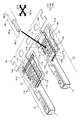
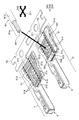
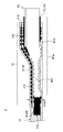
図49は、バレル部とアルミニウム芯線との接触部位の周囲をシール部材で囲んだ従来の圧着端子の一例を示す図である。
FIG. 49 is a diagram showing an example of a conventional crimp terminal in which the periphery of the contact portion between the barrel portion and the aluminum core wire is surrounded by a seal member.
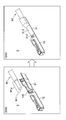
この図49に示されている圧着端子7は、銅合金等の金属板から板金加工によって作製され表面に錫メッキや金メッキが施された、バレル部71と、端子部72と、が所定の軸方向D71に配列されたものである。バレル部71は、アルミニウム芯線W71を有する被覆電線W7におけるアルミニウム芯線W71を露出させた端部W7aに巻き付けられて圧着される部位である。端子部72は、接続対象である不図示のピン端子と接続される雌型端子である。
The crimp terminal 7 shown in FIG. 49 is made of a metal plate such as a copper alloy by sheet metal working, and has a barrel portion 71 and a terminal portion 72 having a predetermined axis with tin plating or gold plating on the surface. They are arranged in the direction D71. The barrel portion 71 is a portion that is wound around and crimped to the end portion W7a of the covered electric wire W7 having the aluminum core wire W71 where the aluminum core wire W71 is exposed. The terminal portion 72 is a female terminal that is connected to a pin terminal (not shown) to be connected.
バレル部71は、軸方向D71と交差する断面形状が略U字型となるように金属板が曲げられた構造となっている。このバレル部71の内面711に被覆電線W7の端部W7aが載置された後、バレル部71が端部W7aに巻き付けられて圧着される。バレル部71の内面711の一部が、端部W7aにおけるアルミニウム芯線W71との接触部位711aとなる。
The barrel portion 71 has a structure in which a metal plate is bent so that a cross-sectional shape intersecting the axial direction D71 is substantially U-shaped. After the end portion W7a of the covered electric wire W7 is placed on the inner surface 711 of the barrel portion 71, the barrel portion 71 is wound around the end portion W7a and crimped. A part of the inner surface 711 of the barrel portion 71 becomes a contact portion 711a with the aluminum core wire W71 at the end portion W7a.
そして、この接触部位711aを囲むように、シール部材73が設けられている。バレル部71が端部W7aに巻き付けられて圧着されると、シール部材73が、接触部位711aの周囲における各所の間隙を密封して水分の浸入を防止する。
And the sealing member 73 is provided so that this contact site | part 711a may be enclosed. When the barrel portion 71 is wound around the end portion W7a and pressure-bonded, the seal member 73 seals gaps at various places around the contact portion 711a to prevent moisture from entering.
ここで、接触部位711aには、この接触部位711aに対する平面視で軸方向D71と交差する交差方向D72に延びる溝が軸方向D71に複数列並べられたセレーション74が形成されている。バレル部71が端部W7aに巻き付けられて圧着されると、セレーション74をなす各溝の縁がアルミニウム芯線W71に食い込むことで、被覆電線W7と圧着端子7との良好な導通が得られる。
Here, the contact part 711a is formed with serrations 74 in which grooves extending in an intersecting direction D72 intersecting the axial direction D71 in a plan view with respect to the contact part 711a are arranged in a plurality of rows in the axial direction D71. When the barrel portion 71 is wound around and crimped to the end portion W7a, the edge of each groove forming the serration 74 bites into the aluminum core wire W71, so that good conduction between the covered electric wire W7 and the crimp terminal 7 is obtained.
しかしながら、図49に一例が示されているような従来の圧着端子では、被覆電線と圧着端子との良好な導通を得るために、バレル部の内面のセレーションの領域をなるべく広く確保する必要がある。シール部材は、このセレーションとアルミニウム芯線との十分な接触を妨げないように設けることとなるので、セレーションの領域が広くなる分、シール部材を設けるスペースが狭くなりがちとなり、製造に困難を伴うことが多い。
However, in the conventional crimp terminal shown in FIG. 49 as an example, in order to obtain good conduction between the covered wire and the crimp terminal, it is necessary to secure a serration area on the inner surface of the barrel portion as much as possible. . Since the seal member is provided so as not to prevent sufficient contact between the serration and the aluminum core wire, the space for providing the seal member tends to be narrowed as the serration area is widened, which is difficult to manufacture. There are many.
また、このような従来の圧着端子では、圧着時にバレル部に掛かる圧力によって、このバレル部に延びが生じる。上記のようにバレル部の内面に、溝が複数列並べられたセレーションが設けられている場合、各溝と直交する軸方向への延びが大きくなりがちとなる。バレル部が延びる際には、シール部材も追随して延びることとなるが、バレル部の延びが大きくなり過ぎると、部分的にシール部材が薄くなって防水性の低下を招く恐れがある。
Further, in such a conventional crimp terminal, the barrel portion is extended by pressure applied to the barrel portion during crimping. As described above, when the inner surface of the barrel portion is provided with serrations in which a plurality of rows of grooves are arranged, the extension in the axial direction perpendicular to the grooves tends to be large. When the barrel portion extends, the seal member also follows. However, if the barrel portion is excessively extended, the seal member may be partially thinned to cause a decrease in waterproofness.
従って、本発明は、上記のような課題に着目し、アルミニウム芯線との接触部位に対する防水性を確保しつつも製造上の困難さが緩和された圧着端子を提供することを目的とする。
Therefore, the present invention pays attention to the above-described problems, and an object thereof is to provide a crimp terminal in which manufacturing difficulty is eased while ensuring waterproofness to a contact portion with an aluminum core wire.
上記課題を解決するために、本発明の圧着端子は、アルミニウム芯線を有する被覆電線における前記アルミニウム芯線を露出させた端部に巻き付けられて圧着されるバレル部と、接続対象と接続される端子部と、が所定の軸方向に配列された圧着端子であって、前記バレル部は、前記被覆電線の前記端部が載せられる、前記軸方向に延在する底板部と、当該底板部に対する平面視で前記軸方向と交差する交差方向の両側に前記底板部から延出した内バレル片及び外バレル片と、を有し、圧着時には前記内バレル片を内側にして前記端部に巻き付けられるものであり、前記外バレル片を前記軸方向に縦断する第1領域、前記アルミニウム芯線よりも前記端子部寄りで前記バレル部の内面を前記交差方向に横断する第2領域、及び前記端部の被覆部分と交差するように前記内面を前記交差方向に横断する第3領域、に亘って設けられ、圧着後に、前記内バレル片と前記外バレル片との間と、筒状となる前記バレル部の前記端子部側の開口と、前記被覆部分と前記バレル部との間と、を密封するシール部材を備え、前記バレル部の前記内面には、当該内面に対する平面視で円形又は楕円形の凹部が複数分散して設けられていることを特徴としている。
In order to solve the above-described problems, a crimp terminal of the present invention includes a barrel portion that is wound around and crimped to an end portion of the covered electric wire having an aluminum core wire, and a terminal portion that is connected to a connection target. Are crimp terminals arranged in a predetermined axial direction, wherein the barrel portion has a bottom plate portion extending in the axial direction on which the end portion of the covered electric wire is placed, and a plan view with respect to the bottom plate portion. The inner barrel piece and the outer barrel piece extending from the bottom plate portion on both sides in the intersecting direction intersecting with the axial direction, and are wound around the end portion with the inner barrel piece facing inward at the time of crimping A first region that longitudinally cuts the outer barrel piece in the axial direction; a second region that crosses the inner surface of the barrel portion in the intersecting direction closer to the terminal portion than the aluminum core wire; and a cover of the end portion A third region that crosses the inner surface in the intersecting direction so as to intersect the portion, and after crimping, between the inner barrel piece and the outer barrel piece, A seal member for sealing the opening on the terminal portion side and between the covering portion and the barrel portion is provided, and the inner surface of the barrel portion has a circular or elliptical concave portion in plan view with respect to the inner surface. It is characterized by being distributed in plural.
本発明の圧着端子では、圧着によって、バレル部の内面に設けられた各凹部の縁がアルミニウム芯線に食い込むことで被覆電線と圧着端子との良好な導通が得られる。即ち、バレル部の内面には、凹部が複数分散して設けられてセレーションが形成されているといえる。セレーションにおける導通の程度は、単位面積当たりでアルミニウム芯線に食い込む部分の長さの合計によって決まる。本発明の圧着端子では、この長さの合計が、円形又は楕円形に形成された凹部の周長の合計となる。他方、例えば図49に示されているセレーション74では、直線状に延在する溝の縁の長さの合計となるが、単位面積当たりで見た場合、この合計よりも、円形又は楕円形に形成された複数の凹部の周長の合計の方が長くなる。言い換えると、本発明の圧着端子によれば、被覆電線と圧着端子との良好な導通を得るのに必要なセレーションの領域を、例えば図49に示されている従来の圧着端子7等に比べて抑えることができる。そして、セレーションの領域が抑えられる分、アルミニウム芯線との接触部位に対する防水性を確保するためにシール部材を設けるスペースを広くとることが可能となり、製造上の困難さを緩和することができる。つまり、本発明の圧着端子によれば、アルミニウム芯線との接触部位に対する防水性を確保しつつも製造上の困難さを緩和することができる。
In the crimping terminal of the present invention, good conduction between the coated electric wire and the crimping terminal can be obtained by crimping the edge of each recess provided on the inner surface of the barrel part into the aluminum core wire. In other words, it can be said that serrations are formed on the inner surface of the barrel portion by providing a plurality of recesses dispersed therein. The degree of conduction in serration is determined by the total length of the portions that cut into the aluminum core wire per unit area. In the crimp terminal of the present invention, the sum of the lengths is the sum of the peripheral lengths of the recesses formed in a circular or elliptical shape. On the other hand, in the serration 74 shown in FIG. 49, for example, the total length of the edge of the groove extending linearly becomes a circle or an ellipse rather than the total when viewed per unit area. The sum of the peripheral lengths of the plurality of formed recesses is longer. In other words, according to the crimp terminal of the present invention, the serration area necessary for obtaining good conduction between the covered electric wire and the crimp terminal is compared with, for example, the conventional crimp terminal 7 shown in FIG. Can be suppressed. Since the serration area is suppressed, a space for providing the seal member can be widened in order to secure the waterproof property for the contact portion with the aluminum core wire, and the manufacturing difficulty can be alleviated. That is, according to the crimp terminal of the present invention, it is possible to alleviate the difficulty in manufacturing while ensuring the waterproof property for the contact portion with the aluminum core wire.
また、円形又は楕円形の凹部は、バレル部の内面の面内方向に凹部を広げようとする力に対する抵抗力が、例えば図49に示されているセレーション74をなす溝等に比べて強い。圧着時にバレル部に掛かる圧力は、まさにバレル部の内面の面内方向に働く力であり、本発明の圧着端子では、このような圧力に対する各凹部における抵抗力が強い。このため、本発明の圧着端子では、圧着時に掛かる圧力によるバレル部の延びが抑制される。その結果、シール部材における延びも抑制されることとなり、高いレベルで防水性を確保することができる。本発明の圧着端子によれば、この意味においても、アルミニウム芯線との接触部位に対する防水性を確保しつつも製造上の困難さを緩和することができる。
In addition, the circular or elliptical concave portion has a stronger resistance to the force to expand the concave portion in the in-plane direction of the inner surface of the barrel portion than, for example, the groove forming the serration 74 shown in FIG. The pressure applied to the barrel portion at the time of crimping is just a force acting in the in-plane direction of the inner surface of the barrel portion, and the crimping terminal of the present invention has a strong resistance force in each recess against such pressure. For this reason, in the crimp terminal of the present invention, extension of the barrel portion due to pressure applied during crimping is suppressed. As a result, extension of the seal member is also suppressed, and waterproofness can be secured at a high level. According to the crimp terminal of the present invention, in this sense as well, it is possible to alleviate the difficulty in manufacturing while ensuring the waterproof property for the contact portion with the aluminum core wire.
ここで、本発明の圧着端子において、前記バレル部の前記内面には、前記第1領域、前記第2領域、及び前記第3領域に、前記シール部材と重なるように溝部が形成されており、複数の前記凹部は、前記溝部を避けて設けられていることが好適である。
Here, in the crimp terminal according to the present invention, a groove portion is formed on the inner surface of the barrel portion so as to overlap the seal member in the first region, the second region, and the third region, It is preferable that the plurality of concave portions are provided so as to avoid the groove portions.
この好適な圧着端子によれば、圧着時に掛かる圧力によるシール部材の動きが、シール部材と重なる溝部によって抑制される。従って、この好適な圧着端子によれば、より高いレベルで防水性を確保しつつも製造上の困難さを緩和することができる。
According to this preferred crimp terminal, the movement of the seal member due to the pressure applied during crimping is suppressed by the groove overlapping the seal member. Therefore, according to this preferred crimp terminal, it is possible to alleviate manufacturing difficulties while ensuring waterproofness at a higher level.
本発明によれば、アルミニウム芯線との接触部位に対する防水性を確保しつつも製造上の困難さが緩和された圧着端子を得ることができる。
According to the present invention, it is possible to obtain a crimp terminal in which manufacturing difficulty is eased while ensuring waterproofness to a contact portion with an aluminum core wire.
以下、本発明の一実施形態について各種説明する。まず、第1実施形態について適宜に変形例を交えながら説明する。
Hereinafter, various embodiments of the present invention will be described. First, the first embodiment will be described with appropriate modifications.
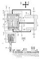
図1は、本発明の第1実施形態にかかる圧着端子を説明するための図である。
FIG. 1 is a view for explaining a crimp terminal according to a first embodiment of the present invention.
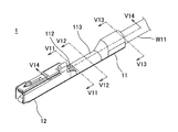
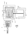
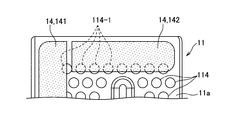
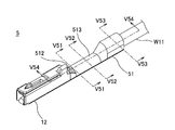
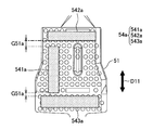
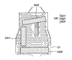
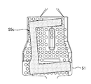
本実施形態における圧着端子1は、アルミニウム芯線W11を有する被覆電線W1におけるアルミニウム芯線W11を露出させた端部W1aに圧着されるものである。圧着端子1は、バレル部11と、端子部12と、シール部材14と、を備えている。尚、図1では、圧着端子1が2つ示されているが、一方の圧着端子1については、バレル部11の内面形状が目視できるように、シール部材14を除いた状態で示されている。
The crimp terminal 1 in this embodiment is crimped to the end W1a of the covered electric wire W1 having the aluminum core wire W11 where the aluminum core wire W11 is exposed. The crimp terminal 1 includes a barrel portion 11, a terminal portion 12, and a seal member 14. In FIG. 1, two crimp terminals 1 are shown, but one crimp terminal 1 is shown with the seal member 14 removed so that the inner surface shape of the barrel portion 11 can be seen. .
バレル部11及び端子部12は、銅合金等の金属板から打抜き加工と板金加工によって作製され表面に錫メッキや金メッキが施される。バレル部11及び端子部12は、所定の軸方向D11に配列されている。ここで、本実施形態では、バレル部11及び端子部12は、帯板状の連結片1aで圧着端子1の複数個分が繋げられた状態でまとめて形成される。バレル部11は、被覆電線W1の端部W1aに、アルミニウム芯線W11と被覆部分W12とを周方向に包むように巻き付けられて圧着される板状の部位である。端子部12は、接続対象である不図示のピン端子と接続される四角筒状の雌型端子である。
The barrel portion 11 and the terminal portion 12 are made from a metal plate such as a copper alloy by punching and sheet metal processing, and the surface thereof is subjected to tin plating or gold plating. The barrel part 11 and the terminal part 12 are arranged in a predetermined axial direction D11. Here, in this embodiment, the barrel part 11 and the terminal part 12 are collectively formed in a state where a plurality of the crimp terminals 1 are connected by the strip-like connecting piece 1a. The barrel portion 11 is a plate-like portion that is wound around the end portion W1a of the covered electric wire W1 so as to wrap the aluminum core wire W11 and the covered portion W12 in the circumferential direction. The terminal portion 12 is a rectangular tubular female terminal that is connected to a pin terminal (not shown) to be connected.
バレル部11は、底板部111と、内バレル片112と、外バレル片113と、を有している。底板部111は、上記の軸方向D11に延在する部位である。内バレル片112及び外バレル片113は、底板部111に対する平面視で軸方向D11と交差する交差方向D12の両側に底板部111から延出した部位である。バレル部11は、被覆電線W1の端部W1aへの圧着時には、後述するように内バレル片112を内側に、外バレル片113を外側にして端部W1aに巻き付けられる。
The barrel portion 11 has a bottom plate portion 111, an inner barrel piece 112, and an outer barrel piece 113. The bottom plate portion 111 is a portion extending in the axial direction D11. The inner barrel piece 112 and the outer barrel piece 113 are portions extending from the bottom plate portion 111 on both sides in the intersecting direction D12 intersecting the axial direction D11 in a plan view with respect to the bottom plate portion 111. As will be described later, the barrel portion 11 is wound around the end portion W1a with the inner barrel piece 112 on the inner side and the outer barrel piece 113 on the outer side at the time of crimping to the end portion W1a of the covered electric wire W1.
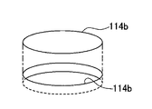
ここで、バレル部11の内面11aには、複数の凹部114が分散して設けられている。各凹部114は、バレル部11の内面11aに対する平面視で円形に形成されている。また、バレル部11の底板部111には、被覆電線W1の端部W1aにおけるアルミニウム芯線W11が載せられる位置に外面側からのプレス加工により凸部115が形成されている。複数の凹部114のうちの一部は、この凸部115上にも形成されている。
Here, on the inner surface 11a of the barrel portion 11, a plurality of concave portions 114 are provided in a distributed manner. Each recess 114 is formed in a circular shape in plan view with respect to the inner surface 11 a of the barrel portion 11. Moreover, the convex part 115 is formed in the bottom plate part 111 of the barrel part 11 by the press work from an outer surface side in the position where the aluminum core wire W11 in the edge part W1a of the covered electric wire W1 is mounted. A part of the plurality of concave portions 114 is also formed on the convex portion 115.
そして、バレル部11の内面11aには、複数の凹部114を平面視で三方から囲むように粘着ジェルシートで形成されたシール部材14が貼付されている。シール部材14は、次のように貼付されている。尚、粘着ジェルシートとしては、例えばアクリル系粘着剤を用いたもの等が挙げられるが、これに限定されるものではない。
Further, a seal member 14 formed of an adhesive gel sheet is attached to the inner surface 11a of the barrel portion 11 so as to surround the plurality of concave portions 114 from three directions in plan view. The seal member 14 is affixed as follows. Examples of the adhesive gel sheet include, but are not limited to, those using an acrylic adhesive.
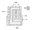
図2は、図1に示されているシール部材がバレル部の内面に貼付される様子を示す模式図である。
FIG. 2 is a schematic diagram showing a state where the seal member shown in FIG. 1 is affixed to the inner surface of the barrel portion.
シール部材14は、粘着ジェルシートで形成されて、バレル部11の内面11aにおける第1領域11a-1、第2領域11a-2、及び第3領域11a-3、の3つの領域に亘って配置される。第1領域11a-1は、外バレル片113を軸方向D11に縦断する領域である。第2領域11a-2は、端部W1aが載せられたときのアルミニウム芯線W11よりも端子部12寄りで内面11aを交差方向D12に横断する領域である。第3領域11a-3は、端部W1aの被覆部分W12と交差するように内面11aを交差方向D12に横断する領域である。
The seal member 14 is formed of an adhesive gel sheet, and is arranged over three regions of the first region 11a-1, the second region 11a-2, and the third region 11a-3 on the inner surface 11a of the barrel part 11. Is done. The first region 11a-1 is a region that vertically cuts the outer barrel piece 113 in the axial direction D11. The second region 11a-2 is a region that crosses the inner surface 11a in the intersecting direction D12 closer to the terminal portion 12 than the aluminum core wire W11 when the end portion W1a is placed. The third region 11a-3 is a region that crosses the inner surface 11a in the intersecting direction D12 so as to intersect with the covering portion W12 of the end W1a.
図1及び図2に示されているように、本実施形態では、シール部材14が、第1シール部分141と、第2シール部分142と、第3シール部分143と、の3つの部分からなる。第1シール部分141は、第1領域11a-1で軸方向D11に帯状に延在する部分である。第2シール部分142は、第2領域11a-2で交差方向D12に帯状に延在する部分である。第3シール部分143は、第3領域11a-3で交差方向D12に帯状に延在する部分である。
As shown in FIGS. 1 and 2, in this embodiment, the seal member 14 is composed of three parts, a first seal part 141, a second seal part 142, and a third seal part 143. . The first seal portion 141 is a portion that extends in a strip shape in the axial direction D11 in the first region 11a-1. The second seal portion 142 is a portion extending in a band shape in the intersecting direction D12 in the second region 11a-2. The third seal portion 143 is a portion extending in a strip shape in the intersecting direction D12 in the third region 11a-3.
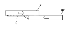
本実施形態では、シール部材14は、第2領域11a-2から第1領域11a-1を経て第3領域11a-3に至る経路11a-4の中途で分割された状態で貼付されている。具体的には、シール部材14が、第2シール部分142と第3シール部分143との両方が、第1シール部分141と分割された状態で貼付されている。また、第2シール部分142及び第3シール部分143は、何れも上記の経路11a-4を軸方向D11に横切って第1シール部分141と分割された状態で貼付されている。第2シール部分142及び第3シール部分143と、第1シール部分141との間には若干の間隙G11が開いている。
In the present embodiment, the seal member 14 is affixed in a state of being divided in the middle of the path 11a-4 from the second area 11a-2 through the first area 11a-1 to the third area 11a-3. Specifically, the seal member 14 is affixed in a state where both the second seal portion 142 and the third seal portion 143 are separated from the first seal portion 141. Further, the second seal portion 142 and the third seal portion 143 are pasted in a state of being divided from the first seal portion 141 across the path 11a-4 in the axial direction D11. A slight gap G11 is opened between the second seal portion 142 and the third seal portion 143, and the first seal portion 141.
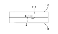
また、本実施形態では、バレル部11の内面11aでは、第1領域11a-1、第2領域11a-2、及び第3領域11a-3に、シール部材14と重なるように溝部116が形成されている。溝部116は、第1領域11a-1では、中途で鋸歯状に曲折しつつ軸方向D11に1本が延びている。第2領域11a-2では、交差方向D12に直線状に1本が延びており、第3領域11a-3では、交差方向D12に直線状に3本が延びて第1領域11a-1側で互いに合流している。そして、複数の凹部114は、溝部116を避けて設けられている。
In the present embodiment, on the inner surface 11a of the barrel portion 11, a groove portion 116 is formed in the first region 11a-1, the second region 11a-2, and the third region 11a-3 so as to overlap the seal member 14. ing. In the first region 11a-1, one groove 116 extends in the axial direction D11 while being bent in a sawtooth shape in the middle. In the second region 11a-2, one straight line extends in the intersecting direction D12, and in the third region 11a-3, three straight lines extend in the intersecting direction D12 and on the first region 11a-1 side. They are joining each other. The plurality of recesses 114 are provided avoiding the groove 116.
第1シール部分141、第2シール部分142、及び第3シール部分143は、各々が第1領域11a-1、第2領域11a-2、及び第3領域11a-3の溝部116と重なるように貼付される。ここで、複数の凹部114は、シール部材14と一部が重なるように設けられている。具体的には、図2に示されているように、最も外バレル片113の縁側の凹部114が、第1領域11a-1と部分的に重なり、最も端子部12側の凹部114が、第2領域11a-2と部分的に重なるように設けられている。その結果、第1領域11a-1に貼付される第1シール部分141及び第2領域11a-2に貼付される第2シール部分142と、一部の凹部114と、が部分的に重なる。
The first seal portion 141, the second seal portion 142, and the third seal portion 143 are overlapped with the grooves 116 of the first region 11a-1, the second region 11a-2, and the third region 11a-3, respectively. Affixed. Here, the plurality of recesses 114 are provided so as to partially overlap the seal member 14. Specifically, as shown in FIG. 2, the concave portion 114 on the edge side of the outer barrel piece 113 partially overlaps the first region 11a-1, and the concave portion 114 on the most terminal portion 12 side is the first concave portion 114. Two regions 11a-2 are provided so as to partially overlap. As a result, the first seal portion 141 attached to the first region 11a-1 and the second seal portion 142 attached to the second region 11a-2 partially overlap with the recess 114.
以上に説明した圧着端子1は、次のような端子製造方法で製造される。
The crimp terminal 1 described above is manufactured by the following terminal manufacturing method.
この端子製造方法では、まず、シール部材14の貼付前の構造物を形成する板金加工工程が行われる。板金加工工程では、バレル部11が、端子部12とともに金属板から形成される。上述したように、本実施形態では、この板金加工工程において、バレル部11及び端子部12が、帯板状の連結片1aで圧着端子1の複数個分が繋げられた状態でまとめて形成される。この板金加工工程では、バレル部11の内面11aにおける複数の凹部114の形成、凸部115の形成、及び溝部116の形成も行われる。
In this terminal manufacturing method, first, a sheet metal processing step for forming a structure before the sealing member 14 is attached is performed. In the sheet metal working process, the barrel portion 11 is formed of a metal plate together with the terminal portion 12. As described above, in this embodiment, in this sheet metal working step, the barrel portion 11 and the terminal portion 12 are formed together in a state where a plurality of the crimp terminals 1 are connected by the strip-like connecting piece 1a. The In this sheet metal working process, formation of a plurality of concave portions 114, formation of the convex portions 115, and formation of the groove portions 116 on the inner surface 11a of the barrel portion 11 are also performed.
続いて、粘着ジェルシートでシール部材14を形成するとともに、シール部材14を、第1領域11a-1、第2領域11a-2、及び第3領域11a-3、に亘って貼付するシール部材貼付工程が行われる。このシール部材貼付工程は、第2領域11a-2から第1領域11a-1を経て第3領域11a-3に至る経路11a-4の中途で分割された状態でシール部材14を貼付する工程である。即ち、上記の第1シール部分141、第2シール部分142、及び第3シール部分143が個別にバレル部11の内面11aに貼付される。
Subsequently, the seal member 14 is formed with an adhesive gel sheet, and the seal member 14 is pasted over the first region 11a-1, the second region 11a-2, and the third region 11a-3. A process is performed. This seal member affixing step is a step of affixing the seal member 14 in a state where it is divided along the path 11a-4 from the second region 11a-2 through the first region 11a-1 to the third region 11a-3. is there. That is, the first seal portion 141, the second seal portion 142, and the third seal portion 143 are individually attached to the inner surface 11 a of the barrel portion 11.
また、シール部材貼付工程では、第1シール部分141、第2シール部分142、及び第3シール部分143について、粘着ジェルシートから型抜きされるとともに、バレル部11の内面11aに貼付される。各シール部分の型抜き用カッターで、バレル部11の内面11aにおける各貼付箇所に向かって粘着ジェルシートを型抜きつつ貼付箇所へと押し付けることで、型抜きと貼付とがほぼ同時に行われる。
Also, in the seal member attaching step, the first seal portion 141, the second seal portion 142, and the third seal portion 143 are removed from the adhesive gel sheet and attached to the inner surface 11a of the barrel portion 11. The die cutting and sticking are performed almost simultaneously by pressing the pressure-sensitive adhesive gel sheet to the sticking place while punching the die toward the sticking place on the inner surface 11a of the barrel portion 11 with the die cutting cutter of each seal portion.
このように製造された圧着端子1は、被覆電線W1の端部W1aに次のように圧着される。
The crimp terminal 1 manufactured in this manner is crimped to the end W1a of the covered electric wire W1 as follows.
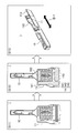
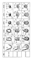
図3は、図1及び図2に示されている圧着端子について、被覆電線の端部に圧着するための準備が整うまでの手順を示す図であり、図4は、図3に示されている手順に続いて圧着端子が被覆電線の端部に圧着されるまでの手順を示す図である。
FIG. 3 is a diagram showing a procedure for the crimping terminal shown in FIGS. 1 and 2 until preparation for crimping to the end of the covered electric wire is completed, and FIG. 4 is shown in FIG. It is a figure which shows the procedure until a crimp terminal is crimped | bonded to the edge part of a covered electric wire following the procedure which is.
図3には、上述した端子製造方法における板金加工工程(S11)及びシール部材貼付工程(S12)も示されている。板金加工工程(S11)で、バレル部11及び端子部12が形成され、シール部材貼付工程(S12)で、シール部材14をなす第1シール部分141、第2シール部分142、及び第3シール部分143が貼付される。
FIG. 3 also shows a sheet metal working step (S11) and a seal member attaching step (S12) in the terminal manufacturing method described above. The barrel portion 11 and the terminal portion 12 are formed in the sheet metal processing step (S11), and the first seal portion 141, the second seal portion 142, and the third seal portion that form the seal member 14 in the seal member attaching step (S12). 143 is affixed.
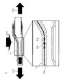
被覆電線W1の端部W1aに圧着するに当たっては、まず、図1に示されている連結片1aから圧着対象の圧着端子1が切り離される。そして、そのバレル部11について、被覆電線W1の端部W1aを載せるための準備として、湾曲変形が行われる(S13)。この湾曲変形は、内バレル片112と外バレル片113とを互いに近づけて、軸方向D11と交差する断面が、略U字型となるように行われる。
In crimping the end portion W1a of the covered electric wire W1, first, the crimp terminal 1 to be crimped is separated from the connecting piece 1a shown in FIG. And about the barrel part 11, curved deformation is performed as preparation for mounting the edge part W1a of the covered electric wire W1 (S13). The bending deformation is performed so that the inner barrel piece 112 and the outer barrel piece 113 are brought close to each other and the cross section intersecting the axial direction D11 is substantially U-shaped.
続いて、湾曲変形後のバレル部11に被覆電線W1の端部W1aが載せられる(S14)。このときには、アルミニウム芯線W11の先端が、第2シール部分142に重ならないように端部W1aが載せられる。尚、多少であれば、アルミニウム芯線W11の先端と、第2シール部分142と、の重なりは許容される。続いて、内バレル片112を内側にして外バレル片113が重ねられるようにバレル部11が端部W1aに巻き付けられて圧着される(S15)。
Subsequently, the end portion W1a of the covered electric wire W1 is placed on the barrel portion 11 after the bending deformation (S14). At this time, the end W1a is placed such that the tip of the aluminum core wire W11 does not overlap the second seal portion 142. In addition, if it is somewhat, the front-end | tip of the aluminum core wire W11 and the 2nd seal | sticker part 142 overlap is permitted. Subsequently, the barrel portion 11 is wound around the end portion W1a so as to overlap the outer barrel piece 113 with the inner barrel piece 112 facing inside (S15).
このような圧着により、シール部材14が、次のように圧着端子1の各所を密封する。
圧 着 By such crimping, the seal member 14 seals the various portions of the crimp terminal 1 as follows.
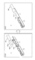
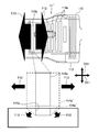
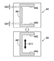
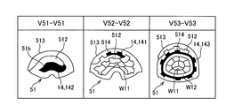
図5は、図4にも示されている圧着後の圧着端子を示す図である。図6は、図5中のV11-V11線断面、V12-V12線断面、及びV13-V13線断面における、圧着作業中の変化を示す図である。
FIG. 5 is a view showing the crimp terminal after crimping, which is also shown in FIG. FIG. 6 is a diagram showing changes during the crimping operation on the V11-V11 line cross section, the V12-V12 line cross section, and the V13-V13 line cross section in FIG.
圧着作業の第1段階(S151)では、凸部115上のアルミニウム芯線W11と、その近傍の被覆部分W12とに巻き付くように内バレル片112と外バレル片113の曲げ加工が開始される。このとき、第1シール部分141がアルミニウム芯線W11に接し、第3シール部分143が被覆部分W12に接し、第2シール部分142の大部分は何れとも略接しないような位置関係となる。巻き付きが若干進んだ第2段階(S152)及び第3段階(S153)では、バレル部11が筒状となる。そして、第1シール部分141が内バレル片112と外バレル片113との間に挟まれ、第3シール部分143が被覆部分W12とバレル部11との間に挟まれた状態で延ばされていく。
In the first stage (S151) of the crimping operation, bending of the inner barrel piece 112 and the outer barrel piece 113 is started so as to be wound around the aluminum core wire W11 on the convex portion 115 and the covering portion W12 in the vicinity thereof. At this time, the first seal portion 141 is in contact with the aluminum core wire W11, the third seal portion 143 is in contact with the covering portion W12, and most of the second seal portion 142 is not substantially in contact with each other. In the second stage (S152) and the third stage (S153) in which the winding is slightly advanced, the barrel portion 11 has a cylindrical shape. Then, the first seal portion 141 is sandwiched between the inner barrel piece 112 and the outer barrel piece 113, and the third seal portion 143 is stretched while being sandwiched between the covering portion W12 and the barrel portion 11. Go.
アルミニウム芯線W11等に圧力が掛かる第4段階(S154)、第5段階(S155)、及び第6段階(S156)で、アルミニウム芯線W11に、複数の凹部114の縁が食い込んでいく。また、このときには、アルミニウム芯線W11の下部に位置する凸部115によってアルミニウム芯線W11の素線がばらされて拡がり、バレル部11とこれらの素線との接触本数が増加する。同時にシール部材14の延びも進行する。
In the fourth stage (S154), the fifth stage (S155), and the sixth stage (S156) in which pressure is applied to the aluminum core wire W11 or the like, the edges of the plurality of recesses 114 bite into the aluminum core wire W11. Further, at this time, the strands of the aluminum core wire W11 are separated and expanded by the convex portions 115 located below the aluminum core wire W11, and the number of contacts between the barrel portion 11 and these strands increases. At the same time, the extension of the seal member 14 also proceeds.
ここで、上述したように、本実施形態では、第2シール部分142及び第3シール部分143と、第1シール部分141との間には若干の間隙G11が開いている。この間隙G11が、圧着時の上記のシール部材14の延びにより塞がる。
Here, as described above, in the present embodiment, a slight gap G11 is opened between the second seal portion 142, the third seal portion 143, and the first seal portion 141. This gap G11 is closed by the extension of the sealing member 14 during the pressure bonding.
図7は、図2に示されている第2シール部分及び第3シール部分と、第1シール部分との間の間隙が、圧着時のシール部材の延びにより塞がる様子を示す模式図である。
FIG. 7 is a schematic view showing a state in which the gap between the second seal portion and the third seal portion shown in FIG. 2 and the first seal portion is closed by the extension of the seal member at the time of crimping.
この図7に示されているように、圧着時には、第2シール部分142及び第3シール部分143が、その長さ方向と一致する交差方向D12に延ばされる。この延びにより、第2シール部分142及び第3シール部分143が、第1シール部分141と繋がり、上記の間隙G11が塞がる。
As shown in FIG. 7, at the time of pressure bonding, the second seal portion 142 and the third seal portion 143 are extended in the intersecting direction D12 that coincides with the length direction thereof. By this extension, the second seal portion 142 and the third seal portion 143 are connected to the first seal portion 141, and the gap G11 is closed.
次に、第6段階(S156)において、内バレル片112と外バレル片113との間と、筒状のバレル部11の端子部12側の開口11bと、被覆部分W12とバレル部11との間と、が延ばされたシール部材14によって密封される。
Next, in the sixth stage (S156), between the inner barrel piece 112 and the outer barrel piece 113, the opening 11b on the terminal portion 12 side of the cylindrical barrel portion 11, the covering portion W12 and the barrel portion 11 It is sealed by the extended seal member 14.
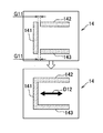
図8は、圧着後に圧着端子のバレル部における各所をシール部材が密封している様子を、図5中のV14-V14線断面で示す図である。この図8に示されているように、内バレル片112と外バレル片113との間は第1シール部分141によって密封され、バレル部11の端子部12側の開口11bは第2シール部分142によって密封される。また、被覆部分W12とバレル部11との間が第3シール部分143によって密封される。
FIG. 8 is a cross-sectional view taken along the line V14-V14 in FIG. 5, showing that the sealing member seals the various portions of the barrel portion of the crimp terminal after crimping. As shown in FIG. 8, the space between the inner barrel piece 112 and the outer barrel piece 113 is sealed by the first seal portion 141, and the opening 11 b on the terminal portion 12 side of the barrel portion 11 is the second seal portion 142. Sealed by. Further, the space between the covering portion W12 and the barrel portion 11 is sealed by the third seal portion 143.
このとき、本実施形態では、圧着後のバレル部11において主として圧力が掛かる図8中上下方向の寸法(以後、クリンプハイトCH11と呼ぶ)が、次のような寸法に設定される。即ち、ある程度の厚みと幅のある粘着ジェルシートで形成されたシール部材14の一部が、バレル部11の開口11bから突出する程度に筒状のバレル部11を潰す寸法に設定される。クリンプハイトCH11をこのような寸法とすることで、バレル部11の開口11bが高いレベルで密封されることとなっている。また、シール部材14の一部は、バレル部11における被覆電線W1の延出側においても、被覆部分W12とバレル部11との間から一部が突出して当該箇所を高いレベルで密封している。言い換えると、シール部材14をなす第1シール部分141、第2シール部分142、及び第3シール部分143の各部分の幅等の寸法は、圧着後のこのような密封に必要十分な寸法となっている。
At this time, in this embodiment, the vertical dimension (hereinafter referred to as crimp height CH11) in FIG. 8 where pressure is mainly applied to the barrel part 11 after crimping is set to the following dimension. That is, the cylindrical barrel portion 11 is sized so that a part of the seal member 14 formed of an adhesive gel sheet having a certain thickness and width protrudes from the opening 11 b of the barrel portion 11. By setting the crimp height CH11 to such dimensions, the opening 11b of the barrel portion 11 is sealed at a high level. Moreover, a part of the sealing member 14 protrudes from between the covering part W12 and the barrel part 11 even on the extending side of the covered electric wire W1 in the barrel part 11, and seals the part at a high level. . In other words, the dimensions such as the width of each of the first seal portion 141, the second seal portion 142, and the third seal portion 143 forming the seal member 14 are dimensions that are necessary and sufficient for such sealing after crimping. ing.
また、シール部材14における各部分を、バレル部11の開口11bや被覆電線W1の延出側から突出する寸法で形成することで、圧着後にこれらの箇所が確かにシール部材14で密封されていることを目視確認することが可能となっている。
Moreover, each part in the sealing member 14 is formed with a dimension that protrudes from the opening 11b of the barrel portion 11 and the extending side of the covered electric wire W1, so that these portions are surely sealed with the sealing member 14 after the crimping. This can be confirmed visually.
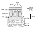
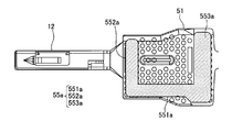
図9は、図1~図8に示されている第1実施形態の圧着端子に対する第1変形例の圧着端子を示す図であり、図10は、図9に示されている第1変形例の圧着端子の、図8と同様の断面を示す図である。尚、図9及び図10では、図1~図8に示されている構成要素と同等な構成要素については、図1~図8と同じ符号が付されており、以下では、これら同等な構成要素についての重複説明を省略する。
9 is a view showing a crimp terminal of a first modification to the crimp terminal of the first embodiment shown in FIGS. 1 to 8, and FIG. 10 is a first modification shown in FIG. It is a figure which shows the cross section similar to FIG. 9 and 10, the same components as those shown in FIGS. 1 to 8 are denoted by the same reference numerals as those in FIGS. 1 to 8. In the following, these equivalent components A duplicate description of elements is omitted.
この第1変形例の圧着端子2は、圧着後のバレル部21における端子部12側(以後、前端部211と呼ぶ)のクリンプハイトCH21が、アルミニウム芯線W11の圧着部212のクリンプハイトCH22よりも大きくなるように圧着される。この場合であっても前端部211のクリンプハイトCH21は、バレル部11の開口11bからシール部材14の一部が突出して高いレベルで密封される寸法となっている。シール部材14をなす第1シール部分141、第2シール部分142、及び第3シール部分143の各部分の幅等の寸法は、圧着後のこのような密封に必要十分な寸法に形成されている。そして、圧着部212のクリンプハイトCH22を上記のように相対的に小さくすることで、アルミニウム芯線W11の圧着を強化し、圧着端子2との接触信頼性を向上させている。
In the crimp terminal 2 of the first modified example, the crimp height CH21 on the terminal section 12 side (hereinafter referred to as the front end section 211) in the barrel section 21 after crimping is more than the crimp height CH22 of the crimp section 212 of the aluminum core wire W11. Crimped to increase. Even in this case, the crimp height CH21 of the front end portion 211 is dimensioned such that a part of the seal member 14 protrudes from the opening 11b of the barrel portion 11 and is sealed at a high level. The first and second seal portions 141, 142, and 143 of the seal member 14 have dimensions such as the width and the like necessary for such sealing after crimping. . The crimp height CH22 of the crimping portion 212 is relatively reduced as described above, whereby the crimping of the aluminum core wire W11 is strengthened and the contact reliability with the crimp terminal 2 is improved.
以上に説明した本実施形態の圧着端子1では、圧着によって、バレル部11の内面11aに設けられた各凹部114の縁がアルミニウム芯線W1aに食い込むことで被覆電線W1と圧着端子1との良好な導通が得られる。そして、粘着ジェルシートで形成されたシール部材14がバレル部11の内面11aに貼付されている。このシール部材14が、圧着後に、内バレル片112と外バレル片113との間と、筒状となるバレル部11の端子部12側の開口11bと、被覆部分W12とバレル部11との間と、を密封する。このシール部材14により、アルミニウム芯線W1aとバレル部11の内面11aとの異種金属接触となる接触部位に対する防水性が確保される。ここで、本実施形態の圧着端子1では、このシール部材14が、上記の第2領域11a-2から第1領域11a-1を経て第3領域11a-3に至る経路11a-4の中途で分割された状態で貼付されている。即ち、防水性を得るために上記のような経路11a-4を辿って複雑な形状となりがちなシール部材14が、分割された個々のピースごとに貼付される。
In the crimp terminal 1 of this embodiment described above, the edge of each concave portion 114 provided on the inner surface 11a of the barrel portion 11 bites into the aluminum core wire W1a by crimping, so that the coated electric wire W1 and the crimp terminal 1 are good. Conductivity is obtained. And the sealing member 14 formed with the adhesive gel sheet is affixed on the inner surface 11a of the barrel part 11. FIG. After the pressure bonding, the seal member 14 is between the inner barrel piece 112 and the outer barrel piece 113, between the opening 11b on the terminal portion 12 side of the cylindrical barrel portion 11, and between the covering portion W12 and the barrel portion 11. And seal. The sealing member 14 ensures waterproofness to a contact portion that is a different metal contact between the aluminum core wire W1a and the inner surface 11a of the barrel portion 11. Here, in the crimp terminal 1 of the present embodiment, the seal member 14 is partway along the path 11a-4 from the second area 11a-2 to the third area 11a-3 through the first area 11a-1. It is affixed in a divided state. That is, in order to obtain waterproofness, the sealing member 14 that tends to have a complicated shape along the path 11a-4 as described above is attached to each divided piece.
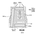
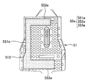
図11は、図1~図8に示されている第1実施形態の圧着端子に対する第2変形例の圧着端子を説明するための図であり、図12は、図11に示されているシール部材がバレル部の内面に貼付される様子を示す模式図である。尚、図11及び図12でも、図1~図8に示されている構成要素と同等な構成要素については、図1~図8と同じ符号が付されており、以下では、これら同等な構成要素についての重複説明を省略する。また、図11でも、圧着端子3が2つ示されているが、一方の圧着端子3については、バレル部11の内面形状が目視できるように、シール部材34を除いた状態で示されている。
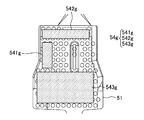
FIG. 11 is a view for explaining a crimp terminal of a second modification to the crimp terminal of the first embodiment shown in FIGS. 1 to 8, and FIG. 12 is a diagram of the seal shown in FIG. It is a schematic diagram which shows a mode that a member is affixed on the inner surface of a barrel part. 11 and 12, the same components as those shown in FIGS. 1 to 8 are denoted by the same reference numerals as those in FIGS. 1 to 8. In the following, these equivalent components will be described. A duplicate description of elements is omitted. Also, in FIG. 11, two crimp terminals 3 are shown, but one crimp terminal 3 is shown in a state where the seal member 34 is removed so that the inner surface shape of the barrel portion 11 can be seen. .
この第2変形例の圧着端子3では、シール部材34が、分割されておらず、第1シール部分341から2本の腕状に第2シール部分342と第3シール部分343とが延出して一体に繋がった平面視でC字状に形成されたものとなっている。このシール部材34が、バレル部11の内面11aにおける溝部116と、複数の凹部114のうちの一部と重なる平面視でC字状の領域11a-5に貼付される。圧着時には、第1シール部分341が内バレル片112と外バレル片113との間を密封し、第2シール部分342が筒状のバレル部11の端子部12側の開口を密封し、第3シール部分343が被覆部分W12とバレル部11との間を密封する。
In the crimp terminal 3 of the second modification, the seal member 34 is not divided, and the second seal portion 342 and the third seal portion 343 extend from the first seal portion 341 in the form of two arms. It is formed in a C shape in plan view connected together. This seal member 34 is affixed to the C-shaped region 11a-5 in a plan view that overlaps the groove 116 on the inner surface 11a of the barrel portion 11 and a part of the plurality of recesses 114. At the time of crimping, the first seal portion 341 seals between the inner barrel piece 112 and the outer barrel piece 113, the second seal portion 342 seals the opening on the terminal portion 12 side of the cylindrical barrel portion 11, and the third The seal portion 343 seals between the covering portion W12 and the barrel portion 11.
この第2変形例に比べれば、上述した第1実施形態の圧着端子1では、3分割された個々のピースごとに貼付されるシール部材14の貼付作業が容易なものとなる。このように、本実施形態の圧着端子1によれば、アルミニウム芯線W1aとの接触部位に対する防水性を確保しつつも製造上の困難さを緩和することができる。
Compared to this second modification, the crimping terminal 1 of the first embodiment described above makes it easier to apply the sealing member 14 that is applied to each of the three divided pieces. Thus, according to the crimp terminal 1 of this embodiment, the difficulty in manufacture can be eased, ensuring the waterproofness with respect to a contact part with the aluminum core wire W1a.
また、本実施形態の圧着端子1では、このシール部材14が予め厚みの決まった粘着ジェルのシートであるので、シール部材14の面積により、上記のような箇所を過不足なく密封するためのジェルの量を製造時に容易かつ正確に調整することができる。本実施形態の圧着端子1によれば、この意味においても、例えばゲル状の樹脂材料をシール用に塗付すること等に比べて、高いレベルで防水性を確保しつつも製造上の困難さを緩和することができる。
Further, in the crimp terminal 1 of this embodiment, since the sealing member 14 is a sheet of adhesive gel having a predetermined thickness, the gel for sealing the above portions without excess or deficiency depending on the area of the sealing member 14. Can be easily and accurately adjusted during manufacture. According to the crimp terminal 1 of the present embodiment, in this sense as well, it is difficult to manufacture while ensuring a high level of waterproofness as compared to, for example, applying a gel-like resin material for sealing. Can be relaxed.
ここで、本実施形態の圧着端子1では、分割されたシール部材14は、図7を参照して上述したように圧着により延ばされて繋がるものとなっているが、圧着による延び率は、軸方向D11よりも交差方向D12の方が大きくなる。本実施形態の圧着端子1では、シール部材14が、上記の経路11a-4を軸方向D11に横切って分割されているので、圧着時には、延び率の大きな交差方向D12の延びにより分割箇所が繋がることとなる。従って、一層高い防水性を確保することができる。
Here, in the crimp terminal 1 of the present embodiment, the divided seal member 14 is connected by being stretched by crimping as described above with reference to FIG. The cross direction D12 is larger than the axial direction D11. In the crimp terminal 1 of the present embodiment, the seal member 14 is divided across the path 11a-4 in the axial direction D11. Therefore, at the time of crimping, the divided portions are connected by the extension in the intersecting direction D12 having a high elongation rate. It will be. Therefore, higher waterproofness can be ensured.
また、本実施形態の圧着端子1では、シール部材14が、第1シール部分141、第2シール部分142、及び第3シール部分143の全てが1本の帯状という非常に単純な形状で貼付されることとなる。これにより、本実施形態の圧着端子1によれば、製造上の困難さを更に緩和することができる。
Further, in the crimp terminal 1 of the present embodiment, the seal member 14 is pasted in a very simple shape in which all of the first seal portion 141, the second seal portion 142, and the third seal portion 143 are in the form of a single band. The Rukoto. Thereby, according to the crimp terminal 1 of this embodiment, the difficulty in manufacture can be eased further.
また、本実施形態の圧着端子1では、バレル部11の内面11aには、シール部材14と重なるように溝部116が形成されており、複数の凹部114は、溝部116を避けて設けられている。これにより、圧着時に掛かる圧力によるシール部材14の動きが、シール部材14と重なる溝部116によって抑制される。従って、本実施形態の圧着端子1によれば、より高いレベルで防水性を確保しつつも製造上の困難さを緩和することができる。
Further, in the crimp terminal 1 of the present embodiment, the groove portion 116 is formed on the inner surface 11 a of the barrel portion 11 so as to overlap the seal member 14, and the plurality of concave portions 114 are provided avoiding the groove portion 116. . Thereby, the movement of the seal member 14 due to the pressure applied at the time of pressure bonding is suppressed by the groove portion 116 overlapping the seal member 14. Therefore, according to the crimp terminal 1 of the present embodiment, it is possible to alleviate manufacturing difficulties while ensuring waterproofness at a higher level.
また、バレル部11の内面11aに設けられる溝部116は、次のような点でも、高いレベルでの防水性の確保に寄与する。
Moreover, the groove part 116 provided in the inner surface 11a of the barrel part 11 contributes to ensuring waterproofness at a high level also in the following points.
図13は、バレル部の内面に設けられる溝部が、高いレベルでの防水性の確保に寄与することを説明するための比較例として、バレル部の内面に溝部が設けられていない例を示す模式図である。また、図14は、バレル部の内面に設けられる溝部が、高いレベルでの防水性の確保に寄与することを図13の例と対比して示す図である。
FIG. 13 is a schematic diagram showing an example in which the groove portion is not provided on the inner surface of the barrel portion as a comparative example for explaining that the groove portion provided on the inner surface of the barrel portion contributes to securing a high level of waterproofness. FIG. Moreover, FIG. 14 is a figure which shows that the groove part provided in the inner surface of a barrel part contributes to ensuring waterproofness at a high level in contrast with the example of FIG.
図13に示されている比較例では、外バレル片113’に貼付されているシール部材14が、圧着時に内バレル片112’の縁によって片側に寄せられる場合がある。これに対し、シール部材14と重なるように溝部116が設けられていると、図14に示されているように、シール部材14が仮に片側に寄せられたとしても、少なくとも溝部116の内部に一部が確保される。これにより、バレル部11の内面11aに設けられる溝部116は、高いレベルでの防水性の確保に寄与することとなっている。
In the comparative example shown in FIG. 13, the seal member 14 affixed to the outer barrel piece 113 'may be moved to one side by the edge of the inner barrel piece 112' during crimping. On the other hand, when the groove 116 is provided so as to overlap the seal member 14, even if the seal member 14 is moved to one side as shown in FIG. Part is secured. Thereby, the groove part 116 provided in the inner surface 11a of the barrel part 11 contributes to ensuring waterproofness at a high level.
また、図1及び図2を参照して説明した第1実施形態の端子製造方法によれば、シール部材14を分割した状態で貼付するので、アルミニウム芯線W1aとの接触部位に対する防水性を確保しつつも製造上の困難さを緩和することができる。また、本実施形態の端子製造方法によれば、粘着ジェルシートでシール部材14を形成することから、高いレベルで防水性を確保しつつも製造上の困難さを緩和することができる。
In addition, according to the terminal manufacturing method of the first embodiment described with reference to FIGS. 1 and 2, since the sealing member 14 is attached in a divided state, the waterproof property to the contact portion with the aluminum core wire W1a is ensured. However, the manufacturing difficulty can be alleviated. Moreover, according to the terminal manufacturing method of this embodiment, since the sealing member 14 is formed with an adhesive gel sheet, manufacturing difficulty can be alleviated while ensuring waterproofness at a high level.
ここで、本実施形態の圧着端子1では、上述したように、圧着によって、バレル部11の内面11aに設けられた各凹部114の縁がアルミニウム芯線W11に食い込むことで被覆電線W1と圧着端子1との良好な導通が得られる。即ち、バレル部11の内面11aには、凹部114が複数分散して設けられセレーションが形成されているといえる。セレーションにおける導通の程度は、単位面積当たりでアルミニウム芯線W11に食い込む部分の長さの合計によって決まる。
Here, in the crimp terminal 1 according to the present embodiment, as described above, the edges of the concave portions 114 provided on the inner surface 11a of the barrel portion 11 bite into the aluminum core wire W11 by crimping, so that the covered electric wire W1 and the crimp terminal 1 are. And good electrical continuity is obtained. That is, it can be said that serrations are formed on the inner surface 11a of the barrel portion 11 by providing a plurality of recesses 114 in a dispersed manner. The degree of conduction in serration is determined by the total length of the portions that bite into the aluminum core wire W11 per unit area.
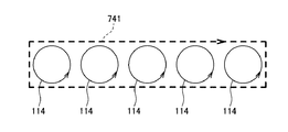
図15は、図1~図8に示されている圧着端子において、アルミニウム芯線との導通の程度が、単位面積当たりでアルミニウム芯線に食い込む部分の長さの合計によって決まることを示す模式図である。
FIG. 15 is a schematic diagram showing that the degree of electrical continuity with the aluminum core wire in the crimp terminal shown in FIGS. 1 to 8 is determined by the total length of the portions that bite into the aluminum core wire per unit area. .
圧着端子1では、アルミニウム芯線W11に食い込む部分の長さの合計が、円形に形成された凹部114の周長の合計となる。他方、例えば図49に示されているセレーション74をなす溝741では、直線状に延在する溝741の縁の長さの合計となるが、単位面積当たりで見た場合、この合計は、円形に形成された複数の凹部114の周長の合計の方が長くなる。言い換えると、本実施形態の圧着端子1によれば、被覆電線W11と圧着端子1との良好な導通を得るのに必要なセレーションの領域を、例えば図49に示されている従来の圧着端子7等に比べて抑えることができる。そして、セレーションの領域が抑えられる分、アルミニウム芯線W11との接触部位に対する防水性を確保するためにシール部材14を設けるスペースを広くとることが可能となり、製造上の困難さを緩和することができる。つまり、本実施形態の圧着端子1によれば、この点においても、アルミニウム芯線W11との接触部位に対する防水性を確保しつつも製造上の困難さを緩和することができる。
In the crimp terminal 1, the sum of the lengths of the portions that bite into the aluminum core wire W11 is the sum of the circumferential lengths of the concave portions 114 formed in a circular shape. On the other hand, for example, in the groove 741 forming the serration 74 shown in FIG. 49, the total length of the edge of the groove 741 extending linearly is the sum of the lengths of the grooves 741 per unit area. The sum of the peripheral lengths of the plurality of recesses 114 formed in the above becomes longer. In other words, according to the crimp terminal 1 of the present embodiment, the serration region necessary for obtaining good conduction between the covered electric wire W11 and the crimp terminal 1 is represented by, for example, the conventional crimp terminal 7 shown in FIG. It can be suppressed compared to etc. Since the serration area is suppressed, a space for providing the seal member 14 can be widened to ensure waterproofness to the contact portion with the aluminum core wire W11, and manufacturing difficulties can be alleviated. . That is, according to the crimp terminal 1 of the present embodiment, in this respect as well, it is possible to alleviate the manufacturing difficulty while ensuring the waterproof property for the contact portion with the aluminum core wire W11.
また、円形の凹部114は、バレル部11の内面11aの面内方向に凹部114を広げようとする力に対する抵抗力が、例えば直線状の溝等に比べて強い。圧着時にバレル部11に掛かる圧力は、まさにバレル部11の内面11aの面内方向に働く力であり、本実施形態の圧着端子1では、このような圧力に対する各凹部における抵抗力が強い。
Further, the circular concave portion 114 has a stronger resistance to a force for expanding the concave portion 114 in the in-plane direction of the inner surface 11a of the barrel portion 11 as compared with, for example, a linear groove. The pressure applied to the barrel part 11 at the time of crimping is just a force acting in the in-plane direction of the inner surface 11a of the barrel part 11, and the crimping terminal 1 of the present embodiment has a strong resistance in each recess against such pressure.
図16は、圧着時にバレル部に掛かる圧力を示す模式図である。
FIG. 16 is a schematic diagram showing the pressure applied to the barrel during crimping.
この図16に示されているように、圧着時には、不図示のプレス装置等により、圧着端子1のバレル部11を押し潰そうとする力F11がバレル部11に掛かる。このような力F11が掛かると、バレル部11には、内面11aの面内方向に凹部114を広げようとする力F12が発生する。
As shown in FIG. 16, at the time of crimping, a force F <b> 11 that tries to crush the barrel portion 11 of the crimp terminal 1 is applied to the barrel portion 11 by a pressing device (not shown) or the like. When such a force F11 is applied, a force F12 is generated in the barrel portion 11 so as to expand the recess 114 in the in-plane direction of the inner surface 11a.
図17は、凹部に替えて直線状の溝が設けられたバレル部を比較例に挙げ、圧着時にバレル部に発生する力による影響について説明する図である。尚、この図17では、図1~図8に示されている構成要素と同等な構成要素については、図1~図8と同じ符号が付されており、以下では、これら同等な構成要素についての重複説明を省略する。
FIG. 17 is a diagram illustrating the influence of the force generated in the barrel part during crimping by taking a barrel part provided with a linear groove instead of the concave part as a comparative example. In FIG. 17, the same components as those shown in FIGS. 1 to 8 are denoted by the same reference numerals as those in FIGS. 1 to 8. In the following, these equivalent components will be described. The duplicate description of is omitted.
この図17の比較例では、セレーションの役割を担うものとして、第1実施形態の圧着端子1における円形の凹部114に替えて、直線状の溝114aが複数並列に設けられている。各溝114aは、軸方向D11と交差する交差方向D12に沿って設けられている。この比較例において図16に示されているような面内方向の力F12が掛かると、各溝114aは、その幅が広がった変形溝114a’へと変形する。各溝114aが変形溝114a’へと変形することで、バレル部11’は軸方向D11に延びることとなる。この場合、バレル部11’に設けられるシール部材14も追随して延ばされるが、この延びが大き過ぎると、例えば、内バレル片112と外バレル片113との間のシール部材14等において、シール部材14のムラ等が生じ、防水性を低下させる恐れがある。
In the comparative example of FIG. 17, instead of the circular recess 114 in the crimp terminal 1 of the first embodiment, a plurality of linear grooves 114a are provided in parallel, assuming the role of serration. Each groove 114a is provided along an intersecting direction D12 that intersects the axial direction D11. In this comparative example, when an in-plane force F12 as shown in FIG. 16 is applied, each groove 114a is deformed into a deformed groove 114a 'whose width is increased. By deforming each groove 114a into a deformed groove 114a ', the barrel portion 11' extends in the axial direction D11. In this case, the seal member 14 provided in the barrel portion 11 ′ is also extended to follow. However, if this extension is too large, for example, the seal member 14 between the inner barrel piece 112 and the outer barrel piece 113 is sealed. There is a possibility that unevenness of the member 14 or the like occurs and the waterproofness is lowered.
この比較例に対し、第1実施形態の圧着端子1では、内面11aの面内方向に凹部114を広げようとする力F12に対する抵抗力が強い。
In contrast to this comparative example, the crimp terminal 1 of the first embodiment has a strong resistance to the force F12 that attempts to expand the recess 114 in the in-plane direction of the inner surface 11a.
図18は、第1実施形態の圧着端子では、凹部を広げようとする力に対する抵抗力が強いことについて説明する図である。
FIG. 18 is a diagram for explaining that the crimping terminal of the first embodiment has a strong resistance to a force for expanding the recess.
円形の凹部114では、その内周面の大部分が、力F12に対して斜めに交差することとなり、凹部114を広げる変形を抑える働きをする。これにより、本実施形態の圧着端子1では、圧着時に掛かる圧力F11によるバレル部11の延びが抑制される。その結果、シール部材14における延びも抑制されることとなり、高いレベルで防水性を確保することができる。本実施形態の圧着端子1によれば、この意味においても、アルミニウム芯線W1aとの接触部位に対する防水性を確保しつつも製造上の困難さを緩和することができる。
In the circular recess 114, most of the inner peripheral surface crosses obliquely with respect to the force F12, and functions to suppress the deformation that widens the recess 114. Thereby, in the crimp terminal 1 of this embodiment, extension of the barrel part 11 by the pressure F11 applied at the time of crimping is suppressed. As a result, extension in the seal member 14 is also suppressed, and waterproofness can be ensured at a high level. According to the crimp terminal 1 of the present embodiment, in this sense as well, it is possible to alleviate the difficulty in manufacturing while ensuring the waterproof property for the contact portion with the aluminum core wire W1a.
以下、第1実施形態の圧着端子1に対する上述した第1変形例及び第2変形例の他の変形例として、バレル部11の内面11aに設けられる凹部114の変形例について説明する。
Hereinafter, a modified example of the recess 114 provided on the inner surface 11a of the barrel portion 11 will be described as another modified example of the first modified example and the second modified example described above with respect to the crimp terminal 1 of the first embodiment.
図19は、図1~図8に示されている第1実施形態の圧着端子に対する第3変形例における凹部を示す図である。また、図20は、図1~図8に示されている第1実施形態の圧着端子に対する第4変形例における凹部を示す図である。また、図21は、図1~図8に示されている第1実施形態の圧着端子に対する第5変形例における凹部を示す図である。
FIG. 19 is a view showing a recess in a third modification of the crimp terminal of the first embodiment shown in FIGS. FIG. 20 is a view showing a recess in a fourth modification of the crimp terminal of the first embodiment shown in FIGS. FIG. 21 is a view showing a recess in a fifth modification of the crimp terminal of the first embodiment shown in FIGS.
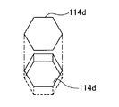
図19に示されている第3変形例における凹部114bは、平面視で楕円形に形成されたものである。また、図20に示されている第4変形例における凹部114cは、平面視で平行四辺形に形成されたものである。また、図21に示されている第5変形例における凹部114dは、平面視で六角形に形成されたものである。
The recess 114b in the third modification shown in FIG. 19 is formed in an elliptical shape in plan view. Moreover, the recessed part 114c in the 4th modification shown by FIG. 20 is formed in the parallelogram in planar view. Moreover, the recessed part 114d in the 5th modification shown by FIG. 21 is formed in the hexagon by planar view.
第1実施形態の圧着端子1における凹部114に対する変形例としては、この他にも平面視で三角形や他の多角形に形成された等が挙げられる。これら何れの変形例も、図17に示されている直線状の溝114aと比較すれば、内面11aの面内方向に広げようとする力F12に対する抵抗力が強い。尚、第3変形例における楕円形の凹部114bについては、第1実施形態における円形の凹部114と同程度の強さを有する。他方、第4変形例における平行四辺形の凹部114cや、第5変形例における六角形の凹部114dについては、第1実施形態における円形の凹部114や第3変形例における楕円形の凹部114bに比べれば抵抗力が弱くなる。
Other examples of modifications to the recess 114 in the crimp terminal 1 of the first embodiment include a triangular shape and other polygons in plan view. In any of these modifications, as compared with the linear groove 114a shown in FIG. 17, the resistance force to the force F12 that attempts to spread in the in-plane direction of the inner surface 11a is strong. Note that the elliptical concave portion 114b in the third modification has the same strength as the circular concave portion 114 in the first embodiment. On the other hand, the parallelogram-shaped recess 114c in the fourth modification and the hexagonal recess 114d in the fifth modification are compared to the circular recess 114 in the first embodiment and the elliptic recess 114b in the third modification. The resistance will be weakened.
ここで、第1実施形態の圧着端子1では、上述したように、バレル部11の内面11aに設けられた複数の凹部114の一部がシール部材14と重なる。第1実施形態の圧着端子1は、この点において、以下のような有利な点を有している。
Here, in the crimp terminal 1 of the first embodiment, as described above, a part of the plurality of recesses 114 provided on the inner surface 11a of the barrel portion 11 overlaps the seal member 14. In this respect, the crimp terminal 1 of the first embodiment has the following advantages.
図22は、複数の凹部の一部がシール部材と重なることによる有利な点について説明する図である。
FIG. 22 is a diagram for explaining an advantage of a part of the plurality of recesses overlapping with the seal member.
第1実施形態の圧着端子1では、シール部材14のうち、まず、外バレル片113側に貼付される第1シール部分141が、複数の凹部114のうち、最も外バレル片113の縁側に位置する凹部114-1と部分的に重なる。これにより、第1シール部分141と重なる位置の凹部114-1を、バレル部11の内面11aに第1シール部分141を設ける際の目印として利用することができる。また、端子部12側に貼付される第2シール部分142も、最も端子部12側に位置する凹部114-1と部分的に重なる。これにより、第2シール部分142と重なる位置の凹部114-1を、バレル部11の内面11aに第2シール部分142を設ける際の目印として利用することができる。本実施形態の圧着端子1によれば、これらの点において製造上の困難さを緩和することができる。また、第1シール部分141や第2シール部分142と重なる凹部114-1は、圧着時に掛かる圧力による第1シール部分141や第2シール部分142の動きを抑制し、より高いレベルでの防水性の確保にも寄与する。このように、本実施形態の圧着端子1によれば、アルミニウム芯線W11との接触部位に対する防水性を確保しつつも、被覆電線W1と圧着端子1との良好な導通のために設けられる凹部114の一部を利用することで、製造上の困難さを緩和することができる。
In the crimp terminal 1 according to the first embodiment, the first seal portion 141 attached to the outer barrel piece 113 side of the seal member 14 is first positioned on the edge side of the outer barrel piece 113 among the plurality of recesses 114. And partially overlaps the recessed portion 114-1. Accordingly, the concave portion 114-1 at a position overlapping with the first seal portion 141 can be used as a mark when the first seal portion 141 is provided on the inner surface 11a of the barrel portion 11. In addition, the second seal portion 142 attached to the terminal portion 12 side also partially overlaps the concave portion 114-1 positioned closest to the terminal portion 12 side. Accordingly, the concave portion 114-1 at a position overlapping the second seal portion 142 can be used as a mark when the second seal portion 142 is provided on the inner surface 11a of the barrel portion 11. According to the crimp terminal 1 of the present embodiment, it is possible to reduce manufacturing difficulties in these respects. Further, the concave portion 114-1 overlapping the first seal portion 141 and the second seal portion 142 suppresses the movement of the first seal portion 141 and the second seal portion 142 due to the pressure applied at the time of pressure bonding, and has a higher level of waterproofness. It also contributes to securing. Thus, according to the crimp terminal 1 of the present embodiment, the recess 114 provided for good conduction between the covered electric wire W1 and the crimp terminal 1 while ensuring the waterproof property for the contact portion with the aluminum core wire W11. By utilizing a part of the above, difficulty in manufacturing can be alleviated.
また、第1実施形態の圧着端子1によれば、圧着時に掛かる圧力によるシール部材14の動きが、シール部材14と重なる溝部116によっても抑制される。第1実施形態の圧着端子1によれば、この点において、より高いレベルで防水性を確保しつつも製造上の困難さを緩和することができる。また、シール部材14と重なる溝部116についても、バレル部11の内面11aにシール部材14を設ける際の目印として利用することができ、この点において製造上の困難さを一層緩和することができる。
Further, according to the crimp terminal 1 of the first embodiment, the movement of the seal member 14 due to the pressure applied during crimping is also suppressed by the groove 116 that overlaps the seal member 14. According to the crimp terminal 1 of the first embodiment, in this respect, difficulty in manufacturing can be alleviated while ensuring waterproofness at a higher level. Moreover, the groove part 116 which overlaps with the seal member 14 can also be used as a mark when the seal member 14 is provided on the inner surface 11a of the barrel part 11, and the manufacturing difficulty can be further alleviated in this respect.
更に、第1実施形態の圧着端子1では、上述したように、複数の凹部114によってセレーションを形成することで、高い導通の程度を確保していることから、シール部材14が多少大目に凹部114と重なったとしても、導通への影響が小さい。このため、シール部材14の貼付に当たって、位置合わせをそれ程厳密に行う必要がなく、この点においても製造上の困難さを一層緩和することができる。
Furthermore, in the crimp terminal 1 according to the first embodiment, as described above, since the serration is formed by the plurality of recesses 114 to ensure a high degree of conduction, the seal member 14 is slightly recessed. Even if it overlaps with 114, the influence on conduction is small. For this reason, when sticking the seal member 14, it is not necessary to perform alignment so strictly, and also in this respect, manufacturing difficulties can be further alleviated.
次に、第1実施形態の圧着端子1に対する上述した第1変形例~第5変形例の他の変形例として、バレル部11の内面11aに貼付されるシール部材14の形状の変形例について説明する。
Next, a modification of the shape of the seal member 14 attached to the inner surface 11a of the barrel portion 11 will be described as another modification of the first to fifth modifications of the crimp terminal 1 of the first embodiment. To do.
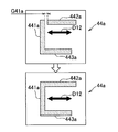
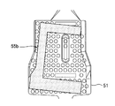
図23は、図1~図8に示されている第1実施形態の圧着端子に対する第6変形例を示す図である。尚、この第6変形例では、シール部材の形状だけでなく、凹部の形状も、第1実施形態の圧着端子1とは異なっている。また、図23では、図1~図8に示されている構成要素と同等な構成要素については、図1~図8と同じ符号が付されており、以下では、これら同等な構成要素についての重複説明を省略する。
FIG. 23 is a view showing a sixth modification of the crimp terminal according to the first embodiment shown in FIGS. In the sixth modified example, not only the shape of the seal member but also the shape of the recess is different from the crimp terminal 1 of the first embodiment. In FIG. 23, constituent elements equivalent to those shown in FIGS. 1 to 8 are denoted by the same reference numerals as those in FIGS. 1 to 8. In the following, these equivalent constituent elements will be described. Duplicate explanation is omitted.
この第6変形例の圧着端子4では、まず、バレル部41の内面41aに設けられる凹部414が、図20に第4変形例として示した平面視で平行四辺形の凹部となっている。
In the crimp terminal 4 of the sixth modified example, first, the concave portion 414 provided on the inner surface 41a of the barrel portion 41 is a parallelogram-shaped concave portion in plan view shown as the fourth modified example in FIG.
そして、この第6変形例におけるシール部材44は、第2シール部分442及び第3シール部分443が、何れも上記の経路11a-4を、交差方向D12に横切って第1シール部分441と分割されている。第2シール部分442及び第3シール部分443と、第1シール部分441との間には若干の間隙G41が軸方向D11に開いている。この間隙G41が、圧着時の上記のシール部材44の延びにより塞がる。
In the seal member 44 in the sixth modified example, the second seal portion 442 and the third seal portion 443 are each divided from the first seal portion 441 across the path 11a-4 in the intersecting direction D12. ing. A slight gap G41 is opened in the axial direction D11 between the second seal portion 442 and the third seal portion 443, and the first seal portion 441. The gap G41 is closed by the extension of the seal member 44 during the pressure bonding.
図24は、図23に示されている第2シール部分及び第3シール部分と、第1シール部分との間の間隙が、圧着時のシール部材の延びにより塞がる様子を示す模式図である。
FIG. 24 is a schematic diagram showing a state in which the gap between the second seal portion and the third seal portion shown in FIG. 23 and the first seal portion is closed by the extension of the seal member at the time of crimping.
この図24に示されているように、圧着時には、第1シール部分441が、その長さ方向と一致する軸方向D11に延ばされる。この延びにより、第2シール部分442及び第3シール部分443が、第1シール部分441と繋がり、上記の間隙G41が塞がる。尚、圧着時の延び率については、軸方向D11よりも交差方向D12の方が大きくなる。このため、延びの程度は、図7等を参照して説明した第1実施形態の場合と比較すると小さくなるが、貼付時に生じる間隙G41を適宜に調節することにより、圧着時に間隙G41を塞いで高いレベルの防水性を確保することができる。
As shown in FIG. 24, at the time of pressure bonding, the first seal portion 441 is extended in the axial direction D11 that coincides with the length direction thereof. By this extension, the second seal portion 442 and the third seal portion 443 are connected to the first seal portion 441, and the gap G41 is closed. In addition, about the elongation rate at the time of pressure bonding, the cross direction D12 becomes larger than the axial direction D11. For this reason, the extent of extension is smaller than that of the first embodiment described with reference to FIG. 7 and the like, but by appropriately adjusting the gap G41 generated at the time of sticking, the gap G41 is closed at the time of crimping. A high level of waterproofness can be ensured.
次に、第1実施形態におけるシール部材14の形状に対する更なる変形例について説明する。
Next, a further modification to the shape of the seal member 14 in the first embodiment will be described.
図25は、図1~図8に示されている第1実施形態の圧着端子に対する第7変形例におけるシール部材を示す図である。また、図26は、図1~図8に示されている第1実施形態の圧着端子に対する第8変形例におけるシール部材を示す図である。また、図27は、図1~図8に示されている第1実施形態の圧着端子に対する第9変形例におけるシール部材を示す図である。また、図28は、図1~図8に示されている第1実施形態の圧着端子に対する第10変形例におけるシール部材を示す図である。
FIG. 25 is a view showing a seal member in a seventh modification to the crimp terminal of the first embodiment shown in FIGS. FIG. 26 is a view showing a seal member in an eighth modification to the crimp terminal of the first embodiment shown in FIGS. FIG. 27 is a view showing a seal member in a ninth modification of the crimp terminal of the first embodiment shown in FIGS. FIG. 28 is a view showing a seal member in a tenth modification of the crimp terminal of the first embodiment shown in FIGS.
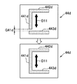
図25に示されている第7変形例におけるシール部材44aは、第1シール部分441aと第2シール部分442aとが分割されて、交差方向D12の間隙G41aが開いている。他方、第1シール部分441aと第3シール部分443aとは繋がっており、両者で平面視でL字状に形成されている。つまり、このシール部材44aは、2分割状態となっている。圧着時には、第2シール部分442aが交差方向D12に延ばされる。この延びにより、第2シール部分442aが、第1シール部分441aと繋がり、上記の間隙G41aが塞がる。
The seal member 44a in the seventh modification shown in FIG. 25 is divided into a first seal portion 441a and a second seal portion 442a, and a gap G41a in the intersecting direction D12 is opened. On the other hand, the 1st seal | sticker part 441a and the 3rd seal | sticker part 443a are connected, and both are formed in the L-shape by planar view. That is, the seal member 44a is in a two-divided state. At the time of crimping, the second seal portion 442a is extended in the intersecting direction D12. By this extension, the second seal portion 442a is connected to the first seal portion 441a, and the gap G41a is closed.
図26に示されている第8変形例におけるシール部材44bは、第1シール部分441bと第2シール部分442bとが分割されて軸方向D11の間隙G41bが開いている。他方、第1シール部分441bと第3シール部分443bとは繋がっており、両者で平面視でL字状に形成されている。圧着時には、第1シール部分441bが軸方向D11に延ばされる。この延びにより、第1シール部分441bが、第2シール部分442bと繋がり、上記の間隙G41bが塞がる。
In the seal member 44b in the eighth modification shown in FIG. 26, the first seal portion 441b and the second seal portion 442b are divided to open the gap G41b in the axial direction D11. On the other hand, the 1st seal | sticker part 441b and the 3rd seal | sticker part 443b are connected, and both are formed in the L-shape by planar view. At the time of pressure bonding, the first seal portion 441b is extended in the axial direction D11. By this extension, the first seal portion 441b is connected to the second seal portion 442b, and the gap G41b is closed.
図27に示されている第9変形例におけるシール部材44cは、第1シール部分441cと第3シール部分443cとが分割されて交差方向D12の間隙G41cが開いている。他方、第1シール部分441cと第2シール部分442cとは繋がっており、両者で平面視で逆L字状に形成されている。圧着時には、第3シール部分443cが交差方向D12に延ばされる。この延びにより、第3シール部分443cが、第1シール部分441cと繋がり、上記の間隙G41cが塞がる。
In the seal member 44c in the ninth modification shown in FIG. 27, the first seal portion 441c and the third seal portion 443c are divided to open a gap G41c in the cross direction D12. On the other hand, the 1st seal | sticker part 441c and the 2nd seal | sticker part 442c are connected, and both are formed in the reverse L shape by planar view. At the time of pressure bonding, the third seal portion 443c is extended in the intersecting direction D12. By this extension, the third seal portion 443c is connected to the first seal portion 441c, and the gap G41c is closed.
図28に示されている第10変形例におけるシール部材44dは、第1シール部分441dと第3シール部分443dとが分割されて軸方向D11の間隙G41dが開いている。他方、第1シール部分441dと第2シール部分442dとは繋がっており、両者で平面視で逆L字状に形成されている。圧着時には、第1シール部分441dが軸方向D11に延ばされる。この延びにより、第1シール部分441dが、第3シール部分443dと繋がり、上記の間隙G41dが塞がる。
In the seal member 44d in the tenth modification shown in FIG. 28, the first seal portion 441d and the third seal portion 443d are divided to open a gap G41d in the axial direction D11. On the other hand, the first seal portion 441d and the second seal portion 442d are connected to each other and formed in an inverted L shape in plan view. At the time of pressure bonding, the first seal portion 441d extends in the axial direction D11. By this extension, the first seal portion 441d is connected to the third seal portion 443d, and the gap G41d is closed.
以上で、第1実施形態について、その変形例も含めた説明を終了し、次に、第2実施形態について、その変形例とともに説明する。この第2実施形態は、バレル部の内面に設けられる複数の凹部が第1実施形態と異なっている。以下では、第2実施形態について、第1実施形態との相違点に注目して説明を行う。
This is the end of the description of the first embodiment including its modifications, and then the second embodiment will be described together with the modifications. The second embodiment is different from the first embodiment in a plurality of recesses provided on the inner surface of the barrel portion. In the following, the second embodiment will be described by paying attention to differences from the first embodiment.
図29は、本発明の第2実施形態にかかる圧着端子を説明するための図である。図30は、図29に示されているシール部材がバレル部の内面に貼付される様子を示す模式図である。尚、図29及び図30では、図1~図8に示されている構成要素と同等な構成要素については、図1~図8と同じ符号が付されており、以下では、これら同等な構成要素についての重複説明を省略する。また、図29でも、圧着端子5が2つ示されているが、一方の圧着端子5については、バレル部51の内面形状が目視できるように、シール部材14を除いた状態で示されている。
FIG. 29 is a view for explaining a crimp terminal according to the second embodiment of the present invention. FIG. 30 is a schematic view showing a state where the seal member shown in FIG. 29 is affixed to the inner surface of the barrel portion. 29 and 30, the same components as those shown in FIGS. 1 to 8 are denoted by the same reference numerals as those in FIGS. 1 to 8. A duplicate description of elements is omitted. Also, in FIG. 29, two crimp terminals 5 are shown, but one crimp terminal 5 is shown with the seal member 14 removed so that the inner surface shape of the barrel portion 51 can be seen. .
本実施形態における圧着端子5では、バレル部51の内面51aには、第1領域51a-1、第2領域51a-2、及び第3領域51a-3を含む略全域に亘って複数の凹部514が分散して設けられている。この内面51aには、アルミニウム芯線W11が載せられる位置に外面側からのプレス加工により凸部515も形成されている。第1領域51a-1は、外バレル片513を軸方向D11に縦断する領域である。第2領域51a-2は、アルミニウム芯線W11よりも端子部12寄りで、底板部511を含むバレル部51の内面51aを、交差方向D12に内バレル片512側と外バレル片513側との間に亘って横断する領域である。また、第3領域51a-3は、端部W1aの被覆部分W12と交差するように内面51aを、交差方向D12に内バレル片512側と外バレル片513側との間に亘って横断する領域である。
In the crimp terminal 5 according to the present embodiment, the inner surface 51a of the barrel portion 51 has a plurality of recesses 514 over substantially the entire area including the first region 51a-1, the second region 51a-2, and the third region 51a-3. Are distributed. On the inner surface 51a, a convex portion 515 is also formed by pressing from the outer surface side at a position where the aluminum core wire W11 is placed. The first region 51a-1 is a region that vertically cuts the outer barrel piece 513 in the axial direction D11. The second region 51a-2 is closer to the terminal portion 12 than the aluminum core wire W11, and the inner surface 51a of the barrel portion 51 including the bottom plate portion 511 is disposed between the inner barrel piece 512 side and the outer barrel piece 513 side in the intersecting direction D12. It is an area that crosses over. The third region 51a-3 is a region that crosses the inner surface 51a between the inner barrel piece 512 side and the outer barrel piece 513 side in the intersecting direction D12 so as to intersect the covering portion W12 of the end W1a. It is.
そして、第1シール部分141、第2シール部分142、及び第3シール部分143からなるシール部材14が、第1領域51a-1、第2領域51a-2、及び第3領域51a-3それぞれの凹部514と重なるように貼付されている。第2シール部分142及び第3シール部分143は、第1シール部分141との間には、第2領域51a-2から第1領域51a-1を経て第3領域51a-3に至る経路51a-4を軸方向D11に横切る間隙G11が開いている。
The seal member 14 including the first seal portion 141, the second seal portion 142, and the third seal portion 143 is provided in each of the first region 51a-1, the second region 51a-2, and the third region 51a-3. It is stuck so as to overlap with the recess 514. Between the second seal portion 142 and the third seal portion 143, a path 51a- between the second region 51a-2, the first region 51a-1, and the third region 51a-3 is formed between the second seal portion 142 and the third seal portion 141. A gap G11 crossing 4 in the axial direction D11 is open.
以上に説明した圧着端子5は、次のような端子製造方法で製造される。
The crimp terminal 5 described above is manufactured by the following terminal manufacturing method.
この端子製造方法では、まず、シール部材14の貼付前の構造物を形成する板金加工工程が行われる。板金加工工程では、バレル部51が、端子部12とともに金属板から形成される。本実施形態でも、この板金加工工程において、バレル部51及び端子部12は、帯板状の連結片5aで圧着端子5の複数個分が繋げられた状態でまとめて形成される。この板金加工工程では、バレル部51の内面51aにおける複数の凹部514の形成、及び凸部515の形成も行われる。
In this terminal manufacturing method, first, a sheet metal processing step for forming a structure before the sealing member 14 is attached is performed. In the sheet metal processing step, the barrel portion 51 is formed of a metal plate together with the terminal portion 12. Also in the present embodiment, in this sheet metal working step, the barrel portion 51 and the terminal portion 12 are formed together in a state where a plurality of the crimp terminals 5 are connected by the strip-like connecting piece 5a. In this sheet metal working process, formation of a plurality of concave portions 514 and formation of convex portions 515 on the inner surface 51a of the barrel portion 51 are also performed.
続いて、粘着ジェルシートでシール部材14を形成するとともに、シール部材14を、第1領域51a-1、第2領域51a-2、及び第3領域51a-3、に亘って貼付するシール部材貼付工程が行われる。このシール部材貼付工程は、上記の経路51a-4の中途で分割された状態でシール部材14を貼付する工程である。即ち、上記の第1シール部分141、第2シール部分142、及び第3シール部分143が個別にバレル部51の内面51aに貼付される。
Subsequently, the seal member 14 is formed with an adhesive gel sheet, and the seal member 14 is applied to the first region 51a-1, the second region 51a-2, and the third region 51a-3. A process is performed. This sealing member sticking step is a step of sticking the sealing member 14 in a state of being divided in the middle of the above-described path 51a-4. That is, the first seal portion 141, the second seal portion 142, and the third seal portion 143 are individually attached to the inner surface 51a of the barrel portion 51.
本実施形態でもシール部材貼付工程では、上述した第1実施形態と同様に、第1シール部分141、第2シール部分142、及び第3シール部分143について、粘着ジェルシートから型抜きされるとともに、バレル部51の内面51aに貼付される。
Also in this embodiment, in the sealing member sticking step, as in the first embodiment described above, the first seal portion 141, the second seal portion 142, and the third seal portion 143 are die-cut from the adhesive gel sheet, Affixed to the inner surface 51 a of the barrel portion 51.
このように製造された圧着端子5は、被覆電線W1の端部W1aに次のように圧着される。
The crimp terminal 5 manufactured in this way is crimped to the end W1a of the covered wire W1 as follows.
図31は、図29及び図30に示されている圧着端子について、被覆電線の端部に圧着するための準備が整うまでの手順を示す図であり、図32は、図31に示されている手順に続いて圧着端子が被覆電線の端部に圧着されるまでの手順を示す図である。
FIG. 31 is a diagram showing a procedure until the crimp terminal shown in FIGS. 29 and 30 is ready for crimping to the end of the covered electric wire, and FIG. 32 is shown in FIG. It is a figure which shows the procedure until a crimp terminal is crimped | bonded to the edge part of a covered electric wire following the procedure which is.
図31には、上述した端子製造方法における板金加工工程(S51)及びシール部材貼付工程(S52)も示されている。板金加工工程(S51)で、バレル部51及び端子部12が形成され、シール部材貼付工程(S52)で、シール部材14をなす第1シール部分141、第2シール部分142、及び第3シール部分143が貼付される。
FIG. 31 also shows a sheet metal working step (S51) and a seal member attaching step (S52) in the terminal manufacturing method described above. The barrel portion 51 and the terminal portion 12 are formed in the sheet metal processing step (S51), and the first seal portion 141, the second seal portion 142, and the third seal portion that form the seal member 14 in the seal member attaching step (S52). 143 is affixed.
被覆電線W1の端部W1aに圧着するに当たっては、まず、図29に示されている連結部5aから圧着対象の圧着端子5が切り離される。そして、そのバレル部51について、被覆電線W1の端部W1aを載せるための準備として、湾曲変形が行われる(S53)。この湾曲変形は、内バレル片512と外バレル片513とを互いに近づけて、軸方向D11と交差する断面が、略U字型となるように行われる。
In crimping the end portion W1a of the covered electric wire W1, first, the crimp terminal 5 to be crimped is cut off from the connecting portion 5a shown in FIG. Then, the barrel portion 51 is subjected to bending deformation as preparation for placing the end portion W1a of the covered electric wire W1 (S53). This bending deformation is performed so that the inner barrel piece 512 and the outer barrel piece 513 are brought close to each other and the cross section intersecting the axial direction D11 is substantially U-shaped.
続いて、湾曲変形後のバレル部51に被覆電線W1の端部W1aが載せられる(S54)。このときには、アルミニウム芯線W11の先端が、第2シール部分142に重ならないように端部W1aが載せられる。尚、多少であれば、アルミニウム芯線W11の先端と、第2シール部分142と、の重なりは許容される。続いて、内バレル片512を内側にして外バレル片513が重ねられるようにバレル部51が端部W1aに巻き付けられて圧着される(S55)。
Subsequently, the end portion W1a of the covered electric wire W1 is placed on the barrel portion 51 after the bending deformation (S54). At this time, the end W1a is placed such that the tip of the aluminum core wire W11 does not overlap the second seal portion 142. In addition, if it is somewhat, the front-end | tip of the aluminum core wire W11 and the 2nd seal | sticker part 142 overlap is permitted. Subsequently, the barrel portion 51 is wound around the end portion W1a so as to overlap the outer barrel piece 513 with the inner barrel piece 512 on the inside (S55).
このような圧着により、シール部材14が、次のように圧着端子5の各所を密封する。
圧 着 By such crimping, the seal member 14 seals the various portions of the crimp terminal 5 as follows.
図33は、図32にも示されている圧着後の圧着端子を示す図である。図34は、図33中のV51-V51線断面、V52-V52線断面、及びV53-V53線断面を示す図である。また、図35は、図33中のV54-V54線断面を示す図である。
FIG. 33 is a view showing the crimp terminal after crimping, which is also shown in FIG. 34 is a diagram showing a cross section taken along line V51-V51, a cross section taken along line V52-V52, and a cross section taken along line V53-V53 in FIG. FIG. 35 is a diagram showing a cross section taken along line V54-V54 in FIG.
本実施形態では、第1実施形態における溝部116の役割を、シール部材14と重なる凹部514が担っている。圧着に際しては、圧着時に掛かる圧力によるシール部材14の動きが、シール部材14と重なる凹部514によって抑制される。圧着の際に、シール部材14における第2シール部分142及び第3シール部分143と、第1シール部分141との間の間隙G11が、第2シール部分142及び第3シール部分143の交差方向D11の延びによって繋がる。圧着後には、内バレル片512と外バレル片513との間が、シール部材14の第1シール部分141で密封される。また、筒状のバレル部51の端子部12側の開口51bが第2シール部分142で密封され、被覆部分W12とバレル部51との間が第3シール部分143で密封される。
In this embodiment, the concave portion 514 that overlaps with the seal member 14 plays the role of the groove 116 in the first embodiment. During the pressure bonding, the movement of the seal member 14 due to the pressure applied during the pressure bonding is suppressed by the recess 514 that overlaps the seal member 14. At the time of crimping, the gap G11 between the second seal portion 142 and the third seal portion 143 and the first seal portion 141 in the seal member 14 is the crossing direction D11 of the second seal portion 142 and the third seal portion 143. It is connected by the extension of. After the pressure bonding, the space between the inner barrel piece 512 and the outer barrel piece 513 is sealed with the first seal portion 141 of the seal member 14. Further, the opening 51 b on the terminal portion 12 side of the cylindrical barrel portion 51 is sealed with the second seal portion 142, and the space between the covering portion W <b> 12 and the barrel portion 51 is sealed with the third seal portion 143.
また、圧着後のバレル部51におけるクリンプハイトCH51は、シール部材14の一部が、バレル部51の開口51bから突出する程度に筒状のバレル部51を潰す寸法に設定される。これにより、バレル部51の開口51bが高いレベルで密封されることとなっている。また、シール部材14の一部は、バレル部51における被覆電線W1の延出側においても、被覆部分W12とバレル部51との間から一部が突出して当該箇所を高いレベルで密封している。シール部材14をなす第1シール部分141、第2シール部分142、及び第3シール部分143の各部分の幅等の寸法は、圧着後のこのような密封に必要十分な寸法に形成されている。また、バレル部51の開口51bや、その反対側からのシール部材14の突出により、それらの箇所での密封を目視確認することが可能となっている。
Further, the crimp height CH51 in the barrel portion 51 after crimping is set to a dimension that crushes the cylindrical barrel portion 51 so that a part of the seal member 14 protrudes from the opening 51b of the barrel portion 51. Thereby, the opening 51b of the barrel part 51 is sealed at a high level. Further, a part of the sealing member 14 protrudes from between the covering part W12 and the barrel part 51 even on the extending side of the covered wire W1 in the barrel part 51 and seals the part at a high level. . The first and second seal portions 141, 142, and 143 of the seal member 14 have dimensions such as the width and the like necessary for such sealing after crimping. . Moreover, it is possible to visually confirm the sealing at these locations by the opening 51b of the barrel portion 51 and the protrusion of the seal member 14 from the opposite side.
以上に説明した第2実施形態の圧着端子5では、圧着によって、バレル部51の内面51aに設けられた各凹部514の縁がアルミニウム芯線W11に食い込むことで被覆電線W1と圧着端子5との良好な導通が得られる。そして、バレル部51の内面に設けられた複数の凹部514の一部が、アルミニウム芯線W11との接触部位に対する防水性を確保するためのシール部材14と重なる。このため、シール部材14と重なる位置の凹部514を、バレル部51の内面51aにシール部材14を設ける際の目印として利用することができ、この点において製造上の困難さを緩和することができる。また、シール部材14と重なる凹部514は、圧着時に掛かる圧力によるシール部材14の動きを抑制し、より高いレベルでの防水性の確保にも寄与する。このように、本実施形態の圧着端子5によれば、アルミニウム芯線W11との接触部位に対する防水性を確保しつつも、被覆電線W1と圧着端子5との良好な導通のために設けられる凹部514の一部を利用することで、製造上の困難さを緩和することができる。
In the crimp terminal 5 of the second embodiment described above, the edges of the recesses 514 provided on the inner surface 51a of the barrel part 51 are bitten into the aluminum core wire W11 by crimping, so that the coated electric wire W1 and the crimp terminal 5 are good. Continuity is obtained. And a part of several recessed part 514 provided in the inner surface of the barrel part 51 overlaps with the sealing member 14 for ensuring the waterproof property with respect to the contact part with the aluminum core wire W11. For this reason, the recessed part 514 of the position which overlaps with the seal member 14 can be used as a mark when the seal member 14 is provided on the inner surface 51a of the barrel part 51, and manufacturing difficulty can be reduced in this respect. . Moreover, the recessed part 514 which overlaps with the sealing member 14 suppresses the movement of the sealing member 14 due to the pressure applied at the time of pressure bonding, and contributes to ensuring waterproofness at a higher level. Thus, according to the crimp terminal 5 of this embodiment, the recessed part 514 provided for favorable conduction | electrical_connection with the covered electric wire W1 and the crimp terminal 5, ensuring the waterproofness with respect to the contact part with the aluminum core wire W11. By utilizing a part of the above, difficulty in manufacturing can be alleviated.
また、本実施形態の圧着端子5によれば、バレル部51の内面形状が、略全域に亘って複数の凹部514が分散して設けられているというように単純化されているので、バレル部51の成形について製造上の困難さを一層緩和することができる。また、シール部材14を設けるに当たっては、凡そバレル部51の外周に沿って設ければ、多少傾いている等といった状態になったとしても、シール部材14と凹部514が重なるように設けることができる。即ち、シール部材14を設けるに当たって、それほど高い位置精度が不要となるので、この点においても、製造上の困難さを一層緩和することができる。
Further, according to the crimp terminal 5 of the present embodiment, since the inner surface shape of the barrel portion 51 is simplified such that a plurality of concave portions 514 are distributed over substantially the entire region, the barrel portion Manufacturing difficulties can be further alleviated for the molding of 51. Further, when the seal member 14 is provided, if the seal member 14 is provided along the outer periphery of the barrel portion 51, the seal member 14 and the recessed portion 514 can be provided so as to overlap even if the seal member 14 is slightly inclined. . That is, when the seal member 14 is provided, the position accuracy is not so high, so that the manufacturing difficulty can be further reduced.
次に、第2実施形態の圧着端子5に対する変形例として、バレル部51に貼付されるシール部材14の貼り方や形状についての変形例について説明する。
Next, as a modification of the crimp terminal 5 of the second embodiment, a modification of the method and shape of the seal member 14 attached to the barrel portion 51 will be described.
図36は、図29~図35に示されている第2実施形態の圧着端子に対する第1変形例におけるシール部材を示す図である。また、図37は、図29~図35に示されている第2実施形態の圧着端子に対する第2変形例におけるシール部材を示す図である。また、図38は、図29~図35に示されている第2実施形態の圧着端子に対する第3変形例におけるシール部材を示す図である。また、図39は、図29~図35に示されている第2実施形態の圧着端子に対する第4変形例におけるシール部材を示す図である。また、図40は、図29~図35に示されている第2実施形態の圧着端子に対する第5変形例におけるシール部材を示す図である。また、図41は、図29~図35に示されている第2実施形態の圧着端子に対する第6変形例におけるシール部材を示す図である。また、図42は、図29~図35に示されている第2実施形態の圧着端子に対する第7変形例におけるシール部材を示す図である。
FIG. 36 is a view showing a seal member in a first modification to the crimp terminal of the second embodiment shown in FIGS. 29 to 35. FIG. FIG. 37 is a view showing a seal member in a second modification to the crimp terminal of the second embodiment shown in FIGS. FIG. 38 is a view showing a seal member in a third modification to the crimp terminal of the second embodiment shown in FIGS. FIG. 39 is a view showing a seal member in a fourth modification to the crimp terminal of the second embodiment shown in FIGS. FIG. 40 is a view showing a seal member in a fifth modification of the crimp terminal of the second embodiment shown in FIGS. FIG. 41 is a view showing a seal member in a sixth modification to the crimp terminal of the second embodiment shown in FIGS. FIG. 42 is a view showing a seal member in a seventh modification of the crimp terminal of the second embodiment shown in FIGS.
図36に示されている第1変形例におけるシール部材54aは、第2シール部分542a及び第3シール部分543aと、第1シール部分541aとの間に、軸方向D11の間隙G51aが開いている。この第1変形例では、圧着時に、第1シール部分541aが軸方向D11に延びて間隙G51aを塞いで高いレベルの防水性を確保することができる。
In the seal member 54a in the first modification shown in FIG. 36, a gap G51a in the axial direction D11 is opened between the second seal portion 542a and the third seal portion 543a and the first seal portion 541a. . In this first modification, the first seal portion 541a extends in the axial direction D11 and closes the gap G51a at the time of pressure bonding, and a high level of waterproofness can be ensured.
図37に示されている第2変形例におけるシール部材54bでは、第1シール部分541bが短めに形成され、シール部材54b全体が、第1変形例に比べると端子部12寄りに偏った位置に貼付される。第2変形例でも、第2シール部分542b及び第3シール部分543bと、第1シール部分541bとの間に軸方向D11の間隙G51bが開いており、圧着時の延びによって間隙G51bが塞がる。この第2変形例では、シール部材54bで密封される領域が狭くはなるが、その貼付位置は、アルミニウム芯線W11とバレル部51との接触部位に対する防水性が得られる位置に設定されていることが前提となっている。この第2変形例は、その上で、バレル部51の略全面に凹部514が形成されていることによる貼付位置の自由度の高さに基づいて、シール部材54bの貼付位置を設定したものである。この第2変形例によれば、第1シール部分541bを短くした分、粘着ジェルシートの使用量を抑えて、コストの低減を図ることができる。
In the seal member 54b in the second modified example shown in FIG. 37, the first seal portion 541b is formed to be short, and the entire seal member 54b is located closer to the terminal portion 12 than in the first modified example. Affixed. Also in the second modified example, the gap G51b in the axial direction D11 is opened between the second seal portion 542b and the third seal portion 543b and the first seal portion 541b, and the gap G51b is closed by the extension during press bonding. In this second modified example, the area sealed by the seal member 54b is narrowed, but the affixing position is set to a position where waterproofing for the contact portion between the aluminum core wire W11 and the barrel portion 51 is obtained. Is the premise. In this second modification, the sticking position of the seal member 54b is set based on the high degree of freedom of the sticking position due to the recesses 514 being formed on the substantially entire surface of the barrel part 51. is there. According to the second modification, the amount of the adhesive gel sheet used can be suppressed by the amount of the first seal portion 541b being shortened, and the cost can be reduced.
図38に示されている第3変形例におけるシール部材54cは、第2シール部分542c及び第3シール部分543cと、第1シール部分541cとの間に、交差方向D12の間隙G51cが開いている。この間隙G51cは、圧着時に、第2シール部分542c及び第3シール部分543cが交差方向D12に延びて塞がる。また、この第3変形例では、バレル部51の略全面に凹部514が形成されていることによる貼付位置の自由度の高さに基づいて、第3シール部分543cの貼付位置が、端子部12寄りに偏った位置となっている。
In the seal member 54c in the third modification shown in FIG. 38, a gap G51c in the intersecting direction D12 is opened between the second seal portion 542c, the third seal portion 543c, and the first seal portion 541c. . The gap G51c is closed by the second seal portion 542c and the third seal portion 543c extending in the intersecting direction D12 during pressure bonding. Further, in this third modification, the sticking position of the third seal portion 543c is determined based on the degree of freedom of the sticking position due to the concave portion 514 being formed on the substantially entire surface of the barrel part 51. The position is biased to the side.
図39に示されている第4変形例におけるシール部材54dは、上述した第3変形例を変形したものとなっており、第1シール部分541dを短くし、第2シール部分542d及び第3シール部分543dの長さを略同じ長さとしたものである。
The seal member 54d in the fourth modification shown in FIG. 39 is a modification of the above-described third modification. The first seal portion 541d is shortened, and the second seal portion 542d and the third seal are used. The length of the portion 543d is substantially the same.
図40に示されている第5変形例におけるシール部材54eは、第2シール部分542e及び第3シール部分543eと、第1シール部分541eとの間に、交差方向D12の間隙G51eが開いている。この間隙G51eは、圧着時に、第2シール部分542e及び第3シール部分543eが交差方向D12に延びて塞がる。また、この第5変形例では、バレル部51の略全面に凹部514が形成されていることによる貼付位置の自由度の高さに基づいて、第1シール部分541eが傾いて貼付されたものとなっている。
In the seal member 54e in the fifth modified example shown in FIG. 40, a gap G51e in the intersecting direction D12 is opened between the second seal portion 542e and the third seal portion 543e and the first seal portion 541e. . The gap G51e is closed when the second seal portion 542e and the third seal portion 543e extend in the intersecting direction D12 during pressure bonding. In the fifth modification, the first seal portion 541e is attached with an inclination on the basis of the degree of freedom of the attaching position due to the formation of the recess 514 on the substantially entire surface of the barrel portion 51. It has become.
図41に示されている第6変形例におけるシール部材54fは、図36に示されている第1変形例を変形したものとなっており、第1シール部分541fを短くしたものである。また、この第6変形例では、バレル部51の略全面に凹部514が形成されていることによる貼付位置の自由度の高さに基づいて、第2シール部分542fが傾いて貼付されたものとなっている。第3シール部分543fは、図36の第1変形例と同等なものとなっている。
41. The seal member 54f in the sixth modification shown in FIG. 41 is a modification of the first modification shown in FIG. 36, and is obtained by shortening the first seal portion 541f. In the sixth modification, the second seal portion 542f is attached with an inclination on the basis of the degree of freedom of the attaching position due to the concave portion 514 formed on the substantially entire surface of the barrel portion 51. It has become. The third seal portion 543f is equivalent to the first modified example of FIG.
図42に示されている第7変形例におけるシール部材54gも、図36に示されている第1変形例を変形したものである。この第7変形例では、第1シール部分541gが短くなり、第2シール部分542gが長くなっている。また、第3シール部分543gが、長くなるとともに幅広に形成されている。
42. The seal member 54g in the seventh modification shown in FIG. 42 is also a modification of the first modification shown in FIG. In the seventh modification, the first seal portion 541g is shortened and the second seal portion 542g is lengthened. Further, the third seal portion 543g is long and wide.
以上、様々な変形例を挙げたように、第2実施形態の圧着端子5では、バレル部51の略全面に凹部514が形成されていることにより、シール部材について、その貼り方や形状を高い自由度で適宜設定することが可能となっている。
As described above, in the crimp terminal 5 according to the second embodiment, since the concave portion 514 is formed on the substantially entire surface of the barrel portion 51, the sticking method and shape of the seal member are high as described in various modifications. It is possible to set appropriately with the degree of freedom.
続いて、第2実施形態の圧着端子5に対する更なる変形例について説明する。
Subsequently, further modifications of the crimp terminal 5 of the second embodiment will be described.
図43は、図29~図35に示されている第2実施形態の圧着端子に対する第8変形例におけるシール部材を示す図である。また、図44は、図29~図35に示されている第2実施形態の圧着端子に対する第9変形例におけるシール部材を示す図である。また、図45は、図29~図35に示されている第2実施形態の圧着端子に対する第10変形例におけるシール部材を示す図である。また、図46は、図29~図35に示されている第2実施形態の圧着端子に対する第11変形例におけるシール部材を示す図である。また、図47は、図29~図35に示されている第2実施形態の圧着端子に対する第12変形例におけるシール部材を示す図である。また、図48は、図29~図35に示されている第2実施形態の圧着端子に対する第13変形例におけるシール部材を示す図である。
43 is a view showing a seal member in an eighth modification to the crimp terminal of the second embodiment shown in FIGS. 29 to 35. FIG. FIG. 44 is a view showing a seal member in a ninth modification to the crimp terminal of the second embodiment shown in FIGS. FIG. 45 is a view showing a seal member in a tenth modification to the crimp terminal of the second embodiment shown in FIGS. FIG. 46 is a view showing a seal member in an eleventh modification of the crimp terminal of the second embodiment shown in FIGS. FIG. 47 is a view showing a seal member in a twelfth modification of the crimp terminal of the second embodiment shown in FIGS. FIG. 48 is a view showing a seal member in a thirteenth modification to the crimp terminal of the second embodiment shown in FIGS.
図43に示されている第8変形例におけるシール部材55aは、分割されておらず、第1シール部分551aから2本の腕状に第2シール部分552aと第3シール部分553aとが延出して一体に繋がった平面視でC字状に形成されたものとなっている。
43 is not divided, and the second seal portion 552a and the third seal portion 553a extend from the first seal portion 551a in the form of two arms. And formed in a C shape in plan view connected together.
以下に説明する図44~図47に示されている各変形例は、何れも上述した第8変形例を変形したものとなっている。
44. Each modification shown in FIGS. 44 to 47 described below is a modification of the eighth modification described above.
図44に示されている第9変形例におけるシール部材55bは、平面視でC字状のシール部材55bが、図44中で、時計回りに傾いた状態でバレル部51に貼付されたものとなっている。
44. The seal member 55b in the ninth modification shown in FIG. 44 is such that a C-shaped seal member 55b in a plan view is affixed to the barrel portion 51 in a state inclined clockwise in FIG. It has become.
図45に示されている第10変形例におけるシール部材55cは、平面視でC字状のシール部材55cが、図45中で、反時計回りに傾いた状態でバレル部51に貼付されたものとなっている。
The seal member 55c in the tenth modification shown in FIG. 45 is obtained by sticking the C-shaped seal member 55c to the barrel portion 51 in a state of being inclined counterclockwise in FIG. It has become.
図46に示されている第11変形例におけるシール部材55dは、短く形成された第2シール部分552dと第3シール部分553dとを第1シール部分551dで繋いだものとなっている。そして、この第11変形例では、シール部材55dが、全体として、バレル部51の内バレル片512寄りに偏った状態で貼付されたものとなっている。
46. The seal member 55d in the eleventh modification shown in FIG. 46 is formed by connecting the second seal portion 552d and the third seal portion 553d, which are formed short, by the first seal portion 551d. In the eleventh modification, the seal member 55d is affixed in a state of being biased toward the inner barrel piece 512 of the barrel portion 51 as a whole.
図47に示されている第12変形例におけるシール部材55eも、短く形成された第2シール部分552eと第3シール部分553eとを第1シール部分551eで繋いだものとなっている。ただし、この第12変形例では、シール部材55eが、全体として、バレル部51の外バレル片513寄りに偏った状態で貼付されたものとなっている。
47. The seal member 55e in the twelfth modification shown in FIG. 47 is also formed by connecting the second seal portion 552e and the third seal portion 553e that are formed short by the first seal portion 551e. However, in the twelfth modification, the seal member 55e is affixed in a state of being biased toward the outer barrel piece 513 of the barrel portion 51 as a whole.
図48に示されている第13変形例におけるシール部材55fは、短く形成された第1シール部分551fで第2シール部分552fと第3シール部分553fとを繋いだものとなっている。そして、この第13変形例では、シール部材55fが、全体として、バレル部51の端子部12寄りに偏った状態で貼付されたものとなっている。
48. The seal member 55f in the thirteenth modification shown in FIG. 48 connects the second seal portion 552f and the third seal portion 553f with a first seal portion 551f formed short. And in this 13th modification, the sealing member 55f is affixed in the state biased near the terminal part 12 of the barrel part 51 as a whole.
以上、様々な変形例を挙げたように、第2実施形態の圧着端子5では、一体となったシール部材を用いる場合でも、バレル部51の略全面に凹部514が形成されていることにより、その貼り方や形状を高い自由度で適宜設定することが可能となっている。
As described above, as described in various modifications, the crimp terminal 5 of the second embodiment has the concave portion 514 formed on the substantially entire surface of the barrel portion 51 even when an integral seal member is used. It is possible to appropriately set the way of attaching and the shape with a high degree of freedom.
尚、以上に説明した実施形態は本発明の代表的な形態を示したに過ぎず、本発明は、この実施形態に限定されるものではない。即ち、本発明の骨子を逸脱しない範囲で種々変形して実施することができる。かかる変形によってもなお本発明の構成を具備する限り、勿論、本発明の範疇に含まれるものである。
Note that the embodiment described above is merely a representative form of the present invention, and the present invention is not limited to this embodiment. That is, various modifications can be made without departing from the scope of the present invention. Of course, such modifications are included in the scope of the present invention as long as they have the configuration of the present invention.
例えば、上述した実施形態や各種変形例では、バレル部に、外面側からのプレス加工によって凸部が設けられた形態が例示されている。しかしながら、バレル部は、この形態に限るものではなく、この凸部に関しては省略してもよい。ただし、凸部を設けることで、アルミニウム芯線の素線をばらして拡げバレル部との接触本数を増加させることができることは上述した通りである。
For example, in the above-described embodiment and various modifications, a form in which a convex portion is provided on the barrel portion by pressing from the outer surface side is illustrated. However, the barrel portion is not limited to this form, and the convex portion may be omitted. However, as described above, it is possible to increase the number of contacts with the barrel portion by disposing and expanding the strands of the aluminum core wire by providing the convex portion.
また、上述した実施形態や各種変形例では、端子部の一例として、何れも、四角筒状の雌型端子としての端子部12を有する圧着端子が例示されている。しかしながら、端子部は、これに限るものではなく、その具体的な形状や接続態様を問うものではない。
Further, in the above-described embodiment and various modifications, as an example of the terminal portion, a crimp terminal having the terminal portion 12 as a rectangular tubular female terminal is exemplified. However, a terminal part is not restricted to this, The specific shape and connection aspect are not ask | required.
1,5 圧着端子
11,51 バレル部
11a,51a 内面
11a-1,51a-1 第1領域
11a-2,51a-2 第2領域
11a-3,51a-3 第3領域
11a-4,51a-4 経路
12 端子部
14 シール部材
111,511 底板部
112,512 内バレル片
113,513 外バレル片
114,514 凹部
115,515 凸部
116 溝部
141 第1シール部分
142 第2シール部分
143 第3シール部分
D11 軸方向
D12 交差方向
G11 間隙
W1 被覆電線
W1a 端部
W11 アルミニウム芯線
W12 被覆部分 1,5 Crimp terminal 11, 51 Barrel portion 11a, 51a Inner surface 11a-1, 51a-1 First region 11a-2, 51a-2 Second region 11a-3, 51a-3 Third region 11a-4, 51a- 4 path 12 terminal portion 14 seal member 111,511 bottom plate portion 112,512 inner barrel piece 113,513 outer barrel piece 114,514 concave portion 115,515 convex portion 116 groove portion 141 first seal portion 142 second seal portion 143 third seal Part D11 Axial direction D12 Crossing direction G11 Gap W1 Covered wire W1a End W11 Aluminum core wire W12 Covered part
11,51 バレル部
11a,51a 内面
11a-1,51a-1 第1領域
11a-2,51a-2 第2領域
11a-3,51a-3 第3領域
11a-4,51a-4 経路
12 端子部
14 シール部材
111,511 底板部
112,512 内バレル片
113,513 外バレル片
114,514 凹部
115,515 凸部
116 溝部
141 第1シール部分
142 第2シール部分
143 第3シール部分
D11 軸方向
D12 交差方向
G11 間隙
W1 被覆電線
W1a 端部
W11 アルミニウム芯線
W12 被覆部分 1,5
Claims (2)
- アルミニウム芯線を有する被覆電線における前記アルミニウム芯線を露出させた端部に巻き付けられて圧着されるバレル部と、接続対象と接続される端子部と、が所定の軸方向に配列された圧着端子であって、
前記バレル部は、前記被覆電線の前記端部が載せられる、前記軸方向に延在する底板部と、当該底板部に対する平面視で前記軸方向と交差する交差方向の両側に前記底板部から延出した内バレル片及び外バレル片と、を有し、圧着時には前記内バレル片を内側にして前記端部に巻き付けられるものであり、
前記外バレル片を前記軸方向に縦断する第1領域、前記アルミニウム芯線よりも前記端子部寄りで前記バレル部の内面を前記交差方向に横断する第2領域、及び前記端部の被覆部分と交差するように前記内面を前記交差方向に横断する第3領域、に亘って設けられ、圧着後に、前記内バレル片と前記外バレル片との間と、筒状となる前記バレル部の前記端子部側の開口と、前記被覆部分と前記バレル部との間と、を密封するシール部材を備え、
前記バレル部の前記内面には、当該内面に対する平面視で円形又は楕円形の凹部が複数分散して設けられていることを特徴とする圧着端子。 In the covered electric wire having an aluminum core wire, the barrel portion wound around the end portion where the aluminum core wire is exposed and crimped, and the terminal portion connected to the connection target are crimp terminals arranged in a predetermined axial direction. And
The barrel portion extends from the bottom plate portion on both sides of the bottom plate portion extending in the axial direction on which the end portion of the covered electric wire is placed and in the crossing direction intersecting the axial direction in a plan view with respect to the bottom plate portion. It has an inner barrel piece and an outer barrel piece taken out, and is wound around the end portion with the inner barrel piece inside when crimped,
A first region that longitudinally cuts the outer barrel piece in the axial direction, a second region that crosses the inner surface of the barrel portion in the intersecting direction and closer to the terminal portion than the aluminum core wire, and intersects the covering portion of the end portion The terminal portion of the barrel portion is provided between the inner barrel piece and the outer barrel piece after crimping, and is provided over a third region that crosses the inner surface in the intersecting direction. A seal member that seals the opening on the side and between the covering portion and the barrel portion;
A crimp terminal according to claim 1, wherein a plurality of circular or elliptical concave portions are provided on the inner surface of the barrel portion in a plan view with respect to the inner surface. - 前記バレル部の前記内面には、前記第1領域、前記第2領域、及び前記第3領域に、前記シール部材と重なるように溝部が形成されており、
複数の前記凹部は、前記溝部を避けて設けられていることを特徴とする請求項1に記載の圧着端子。 A groove portion is formed on the inner surface of the barrel portion so as to overlap the seal member in the first region, the second region, and the third region,
The crimp terminal according to claim 1, wherein the plurality of concave portions are provided so as to avoid the groove portions.
Priority Applications (3)
| Application Number | Priority Date | Filing Date | Title |
|---|---|---|---|
| EP17887306.3A EP3565061B1 (en) | 2016-12-27 | 2017-04-26 | Crimp terminal |
| CN201780073008.2A CN110024227B (en) | 2016-12-27 | 2017-04-26 | Crimping terminal |
| US16/420,559 US10756449B2 (en) | 2016-12-27 | 2019-05-23 | Crimp terminal |
Applications Claiming Priority (2)
| Application Number | Priority Date | Filing Date | Title |
|---|---|---|---|
| JP2016253772A JP6858552B2 (en) | 2016-12-27 | 2016-12-27 | Crimping terminal |
| JP2016-253772 | 2016-12-27 |
Related Child Applications (1)
| Application Number | Title | Priority Date | Filing Date |
|---|---|---|---|
| US16/420,559 Continuation US10756449B2 (en) | 2016-12-27 | 2019-05-23 | Crimp terminal |
Publications (1)
| Publication Number | Publication Date |
|---|---|
| WO2018123101A1 true WO2018123101A1 (en) | 2018-07-05 |
Family
ID=62710185
Family Applications (1)
| Application Number | Title | Priority Date | Filing Date |
|---|---|---|---|
| PCT/JP2017/016504 WO2018123101A1 (en) | 2016-12-27 | 2017-04-26 | Crimp terminal |
Country Status (5)
| Country | Link |
|---|---|
| US (1) | US10756449B2 (en) |
| EP (1) | EP3565061B1 (en) |
| JP (1) | JP6858552B2 (en) |
| CN (1) | CN110024227B (en) |
| WO (1) | WO2018123101A1 (en) |
Cited By (1)
| Publication number | Priority date | Publication date | Assignee | Title |
|---|---|---|---|---|
| DE102019109460A1 (en) * | 2019-04-10 | 2020-10-15 | Te Connectivity Germany Gmbh | Crimp contact |
Families Citing this family (2)
| Publication number | Priority date | Publication date | Assignee | Title |
|---|---|---|---|---|
| JP6803877B2 (en) * | 2018-07-09 | 2020-12-23 | 矢崎総業株式会社 | Wire with terminal |
| US11264735B1 (en) * | 2020-08-28 | 2022-03-01 | TE Connectivity Services Gmbh | Electrical terminal for terminating a wide size range of magnet wires |
Citations (4)
| Publication number | Priority date | Publication date | Assignee | Title |
|---|---|---|---|---|
| JPS55108192A (en) * | 1979-02-13 | 1980-08-19 | Sumitomo Electric Industries | Method of solderless connecting terminal of aluminum conductor wire |
| JPS5940198B2 (en) | 1977-04-12 | 1984-09-28 | 川研フアインケミカル株式会社 | Improved solid detergent |
| JP2015079687A (en) * | 2013-10-18 | 2015-04-23 | 矢崎総業株式会社 | Crimping terminal |
| JP2015201269A (en) * | 2014-04-04 | 2015-11-12 | 矢崎総業株式会社 | Connection structure of crimp terminal and wire |
Family Cites Families (26)
| Publication number | Priority date | Publication date | Assignee | Title |
|---|---|---|---|---|
| DE19549174A1 (en) * | 1995-10-28 | 1997-07-03 | Bosch Gmbh Robert | Contact element with crimp section |
| JP3566541B2 (en) * | 1998-03-31 | 2004-09-15 | 矢崎総業株式会社 | Waterproof connector and waterproofing method |
| JP2009230998A (en) * | 2008-03-21 | 2009-10-08 | Autonetworks Technologies Ltd | Electric wire with terminal fitting and method of manufacturing the same |
| JP5146187B2 (en) * | 2008-08-06 | 2013-02-20 | 住友電装株式会社 | Terminal fitting and wire harness |
| JP2010044913A (en) * | 2008-08-11 | 2010-02-25 | Mitsubishi Materials Corp | Crimp connection terminal |
| JP2011096452A (en) * | 2009-10-28 | 2011-05-12 | Yazaki Corp | Crimping terminal |
| JP5606115B2 (en) * | 2010-03-23 | 2014-10-15 | 矢崎総業株式会社 | Connection structure of crimp terminal to wire |
| CN102859795B (en) * | 2010-03-30 | 2015-08-19 | 古河电气工业株式会社 | Crimp type terminal, connecting structure body and connector |
| JP5675205B2 (en) * | 2010-08-05 | 2015-02-25 | 矢崎総業株式会社 | Crimp terminal |
| JP2012059438A (en) * | 2010-09-07 | 2012-03-22 | Sumitomo Wiring Syst Ltd | Waterproof connector |
| JP5953591B2 (en) * | 2012-04-05 | 2016-07-20 | 矢崎総業株式会社 | Crimping the crimp terminal to the wire |
| JP5899593B2 (en) * | 2012-07-31 | 2016-04-06 | 矢崎総業株式会社 | Aluminum wire with crimp terminal |
| CN202930577U (en) * | 2012-11-30 | 2013-05-08 | 浙江荣得利航空部件有限公司 | Lug |
| WO2014129084A1 (en) * | 2013-02-21 | 2014-08-28 | 古河電気工業株式会社 | Crimp terminal, electrical wire with attached terminal, and wire-harness structure |
| DE102013203796A1 (en) * | 2013-03-06 | 2014-09-11 | Tyco Electronics Amp Gmbh | Electric crimp contact device |
| JP6063788B2 (en) * | 2013-03-19 | 2017-01-18 | 矢崎総業株式会社 | Manufacturing method of terminal fitting and electric wire with terminal |
| DE102013205235A1 (en) * | 2013-03-25 | 2014-09-25 | Tyco Electronics Amp Gmbh | crimp |
| DE112014003899T5 (en) * | 2013-08-26 | 2016-06-09 | Yazaki Corporation | Connection structure of a crimping terminal with respect to a wire |
| US9666956B2 (en) * | 2014-05-19 | 2017-05-30 | Yazaki Corporation | Minute current crimping terminal and minute current wire harness |
| WO2015194640A1 (en) * | 2014-06-19 | 2015-12-23 | 株式会社フジクラ | Crimping terminal |
| JP5940198B2 (en) | 2015-06-18 | 2016-06-29 | 古河電気工業株式会社 | Crimp terminal, connection structure and connector |
| JP6422851B2 (en) * | 2015-12-16 | 2018-11-14 | 矢崎総業株式会社 | Crimping terminal manufacturing method |
| JP6423783B2 (en) * | 2015-12-16 | 2018-11-14 | 矢崎総業株式会社 | Crimp terminal |
| US9853368B2 (en) * | 2016-05-03 | 2017-12-26 | Te Connectivity Corporation | Electrical crimp terminal |
| JP6822834B2 (en) * | 2016-12-27 | 2021-01-27 | 矢崎総業株式会社 | Crimping terminal and terminal manufacturing method |
| JP6904147B2 (en) * | 2017-08-01 | 2021-07-14 | 株式会社オートネットワーク技術研究所 | Wire with terminal |
-
2016
- 2016-12-27 JP JP2016253772A patent/JP6858552B2/en active Active
-
2017
- 2017-04-26 EP EP17887306.3A patent/EP3565061B1/en active Active
- 2017-04-26 CN CN201780073008.2A patent/CN110024227B/en active Active
- 2017-04-26 WO PCT/JP2017/016504 patent/WO2018123101A1/en unknown
-
2019
- 2019-05-23 US US16/420,559 patent/US10756449B2/en active Active
Patent Citations (4)
| Publication number | Priority date | Publication date | Assignee | Title |
|---|---|---|---|---|
| JPS5940198B2 (en) | 1977-04-12 | 1984-09-28 | 川研フアインケミカル株式会社 | Improved solid detergent |
| JPS55108192A (en) * | 1979-02-13 | 1980-08-19 | Sumitomo Electric Industries | Method of solderless connecting terminal of aluminum conductor wire |
| JP2015079687A (en) * | 2013-10-18 | 2015-04-23 | 矢崎総業株式会社 | Crimping terminal |
| JP2015201269A (en) * | 2014-04-04 | 2015-11-12 | 矢崎総業株式会社 | Connection structure of crimp terminal and wire |
Non-Patent Citations (1)
| Title |
|---|
| See also references of EP3565061A4 |
Cited By (1)
| Publication number | Priority date | Publication date | Assignee | Title |
|---|---|---|---|---|
| DE102019109460A1 (en) * | 2019-04-10 | 2020-10-15 | Te Connectivity Germany Gmbh | Crimp contact |
Also Published As
| Publication number | Publication date |
|---|---|
| US10756449B2 (en) | 2020-08-25 |
| CN110024227A (en) | 2019-07-16 |
| EP3565061A4 (en) | 2019-12-25 |
| JP2018106993A (en) | 2018-07-05 |
| JP6858552B2 (en) | 2021-04-14 |
| CN110024227B (en) | 2021-05-25 |
| EP3565061A1 (en) | 2019-11-06 |
| EP3565061B1 (en) | 2021-04-07 |
| US20190280399A1 (en) | 2019-09-12 |
Similar Documents
| Publication | Publication Date | Title |
|---|---|---|
| WO2018123101A1 (en) | Crimp terminal | |
| WO2018123102A1 (en) | Crimp terminal | |
| WO2018123100A1 (en) | Crimp terminal and crimp terminal production method | |
| WO2018123099A1 (en) | Crimp terminal | |
| US9368953B2 (en) | Terminal-formed wire and manufacturing method thereof | |
| WO2018123098A1 (en) | Terminal connection method | |
| WO2018123097A1 (en) | Terminal-equipped electric wire and terminal production method | |
| JP2010021015A (en) | Terminal fitting and electric cable with terminal |
Legal Events
| Date | Code | Title | Description |
|---|---|---|---|
| 121 | Ep: the epo has been informed by wipo that ep was designated in this application |
Ref document number: 17887306 Country of ref document: EP Kind code of ref document: A1 |
|
| NENP | Non-entry into the national phase |
Ref country code: DE |
|
| ENP | Entry into the national phase |
Ref document number: 2017887306 Country of ref document: EP Effective date: 20190729 |