WO2018116795A1 - Driving assistance system and driving assistance device - Google Patents
Driving assistance system and driving assistance device Download PDFInfo
- Publication number
- WO2018116795A1 WO2018116795A1 PCT/JP2017/043433 JP2017043433W WO2018116795A1 WO 2018116795 A1 WO2018116795 A1 WO 2018116795A1 JP 2017043433 W JP2017043433 W JP 2017043433W WO 2018116795 A1 WO2018116795 A1 WO 2018116795A1
- Authority
- WO
- WIPO (PCT)
- Prior art keywords
- vehicle
- width
- unit
- road
- passing
- Prior art date
Links
Images


Classifications
-
- B—PERFORMING OPERATIONS; TRANSPORTING
- B60—VEHICLES IN GENERAL
- B60W—CONJOINT CONTROL OF VEHICLE SUB-UNITS OF DIFFERENT TYPE OR DIFFERENT FUNCTION; CONTROL SYSTEMS SPECIALLY ADAPTED FOR HYBRID VEHICLES; ROAD VEHICLE DRIVE CONTROL SYSTEMS FOR PURPOSES NOT RELATED TO THE CONTROL OF A PARTICULAR SUB-UNIT
- B60W30/00—Purposes of road vehicle drive control systems not related to the control of a particular sub-unit, e.g. of systems using conjoint control of vehicle sub-units, or advanced driver assistance systems for ensuring comfort, stability and safety or drive control systems for propelling or retarding the vehicle
- B60W30/18—Propelling the vehicle
- B60W30/18009—Propelling the vehicle related to particular drive situations
- B60W30/18163—Lane change; Overtaking manoeuvres
-
- B—PERFORMING OPERATIONS; TRANSPORTING
- B60—VEHICLES IN GENERAL
- B60W—CONJOINT CONTROL OF VEHICLE SUB-UNITS OF DIFFERENT TYPE OR DIFFERENT FUNCTION; CONTROL SYSTEMS SPECIALLY ADAPTED FOR HYBRID VEHICLES; ROAD VEHICLE DRIVE CONTROL SYSTEMS FOR PURPOSES NOT RELATED TO THE CONTROL OF A PARTICULAR SUB-UNIT
- B60W30/00—Purposes of road vehicle drive control systems not related to the control of a particular sub-unit, e.g. of systems using conjoint control of vehicle sub-units, or advanced driver assistance systems for ensuring comfort, stability and safety or drive control systems for propelling or retarding the vehicle
- B60W30/08—Active safety systems predicting or avoiding probable or impending collision or attempting to minimise its consequences
- B60W30/095—Predicting travel path or likelihood of collision
- B60W30/0953—Predicting travel path or likelihood of collision the prediction being responsive to vehicle dynamic parameters
-
- B—PERFORMING OPERATIONS; TRANSPORTING
- B60—VEHICLES IN GENERAL
- B60W—CONJOINT CONTROL OF VEHICLE SUB-UNITS OF DIFFERENT TYPE OR DIFFERENT FUNCTION; CONTROL SYSTEMS SPECIALLY ADAPTED FOR HYBRID VEHICLES; ROAD VEHICLE DRIVE CONTROL SYSTEMS FOR PURPOSES NOT RELATED TO THE CONTROL OF A PARTICULAR SUB-UNIT
- B60W30/00—Purposes of road vehicle drive control systems not related to the control of a particular sub-unit, e.g. of systems using conjoint control of vehicle sub-units, or advanced driver assistance systems for ensuring comfort, stability and safety or drive control systems for propelling or retarding the vehicle
- B60W30/08—Active safety systems predicting or avoiding probable or impending collision or attempting to minimise its consequences
- B60W30/095—Predicting travel path or likelihood of collision
- B60W30/0956—Predicting travel path or likelihood of collision the prediction being responsive to traffic or environmental parameters
-
- B—PERFORMING OPERATIONS; TRANSPORTING
- B60—VEHICLES IN GENERAL
- B60W—CONJOINT CONTROL OF VEHICLE SUB-UNITS OF DIFFERENT TYPE OR DIFFERENT FUNCTION; CONTROL SYSTEMS SPECIALLY ADAPTED FOR HYBRID VEHICLES; ROAD VEHICLE DRIVE CONTROL SYSTEMS FOR PURPOSES NOT RELATED TO THE CONTROL OF A PARTICULAR SUB-UNIT
- B60W40/00—Estimation or calculation of non-directly measurable driving parameters for road vehicle drive control systems not related to the control of a particular sub unit, e.g. by using mathematical models
- B60W40/02—Estimation or calculation of non-directly measurable driving parameters for road vehicle drive control systems not related to the control of a particular sub unit, e.g. by using mathematical models related to ambient conditions
- B60W40/06—Road conditions
-
- B—PERFORMING OPERATIONS; TRANSPORTING
- B60—VEHICLES IN GENERAL
- B60W—CONJOINT CONTROL OF VEHICLE SUB-UNITS OF DIFFERENT TYPE OR DIFFERENT FUNCTION; CONTROL SYSTEMS SPECIALLY ADAPTED FOR HYBRID VEHICLES; ROAD VEHICLE DRIVE CONTROL SYSTEMS FOR PURPOSES NOT RELATED TO THE CONTROL OF A PARTICULAR SUB-UNIT
- B60W40/00—Estimation or calculation of non-directly measurable driving parameters for road vehicle drive control systems not related to the control of a particular sub unit, e.g. by using mathematical models
- B60W40/10—Estimation or calculation of non-directly measurable driving parameters for road vehicle drive control systems not related to the control of a particular sub unit, e.g. by using mathematical models related to vehicle motion
- B60W40/105—Speed
-
- B—PERFORMING OPERATIONS; TRANSPORTING
- B60—VEHICLES IN GENERAL
- B60W—CONJOINT CONTROL OF VEHICLE SUB-UNITS OF DIFFERENT TYPE OR DIFFERENT FUNCTION; CONTROL SYSTEMS SPECIALLY ADAPTED FOR HYBRID VEHICLES; ROAD VEHICLE DRIVE CONTROL SYSTEMS FOR PURPOSES NOT RELATED TO THE CONTROL OF A PARTICULAR SUB-UNIT
- B60W40/00—Estimation or calculation of non-directly measurable driving parameters for road vehicle drive control systems not related to the control of a particular sub unit, e.g. by using mathematical models
- B60W40/12—Estimation or calculation of non-directly measurable driving parameters for road vehicle drive control systems not related to the control of a particular sub unit, e.g. by using mathematical models related to parameters of the vehicle itself, e.g. tyre models
-
- B—PERFORMING OPERATIONS; TRANSPORTING
- B60—VEHICLES IN GENERAL
- B60W—CONJOINT CONTROL OF VEHICLE SUB-UNITS OF DIFFERENT TYPE OR DIFFERENT FUNCTION; CONTROL SYSTEMS SPECIALLY ADAPTED FOR HYBRID VEHICLES; ROAD VEHICLE DRIVE CONTROL SYSTEMS FOR PURPOSES NOT RELATED TO THE CONTROL OF A PARTICULAR SUB-UNIT
- B60W50/00—Details of control systems for road vehicle drive control not related to the control of a particular sub-unit, e.g. process diagnostic or vehicle driver interfaces
- B60W50/08—Interaction between the driver and the control system
- B60W50/14—Means for informing the driver, warning the driver or prompting a driver intervention
-
- G—PHYSICS
- G08—SIGNALLING
- G08G—TRAFFIC CONTROL SYSTEMS
- G08G1/00—Traffic control systems for road vehicles
- G08G1/16—Anti-collision systems
-
- B—PERFORMING OPERATIONS; TRANSPORTING
- B60—VEHICLES IN GENERAL
- B60W—CONJOINT CONTROL OF VEHICLE SUB-UNITS OF DIFFERENT TYPE OR DIFFERENT FUNCTION; CONTROL SYSTEMS SPECIALLY ADAPTED FOR HYBRID VEHICLES; ROAD VEHICLE DRIVE CONTROL SYSTEMS FOR PURPOSES NOT RELATED TO THE CONTROL OF A PARTICULAR SUB-UNIT
- B60W2552/00—Input parameters relating to infrastructure
-
- B—PERFORMING OPERATIONS; TRANSPORTING
- B60—VEHICLES IN GENERAL
- B60W—CONJOINT CONTROL OF VEHICLE SUB-UNITS OF DIFFERENT TYPE OR DIFFERENT FUNCTION; CONTROL SYSTEMS SPECIALLY ADAPTED FOR HYBRID VEHICLES; ROAD VEHICLE DRIVE CONTROL SYSTEMS FOR PURPOSES NOT RELATED TO THE CONTROL OF A PARTICULAR SUB-UNIT
- B60W2554/00—Input parameters relating to objects
- B60W2554/40—Dynamic objects, e.g. animals, windblown objects
-
- B—PERFORMING OPERATIONS; TRANSPORTING
- B60—VEHICLES IN GENERAL
- B60W—CONJOINT CONTROL OF VEHICLE SUB-UNITS OF DIFFERENT TYPE OR DIFFERENT FUNCTION; CONTROL SYSTEMS SPECIALLY ADAPTED FOR HYBRID VEHICLES; ROAD VEHICLE DRIVE CONTROL SYSTEMS FOR PURPOSES NOT RELATED TO THE CONTROL OF A PARTICULAR SUB-UNIT
- B60W2554/00—Input parameters relating to objects
- B60W2554/80—Spatial relation or speed relative to objects
- B60W2554/801—Lateral distance
-
- B—PERFORMING OPERATIONS; TRANSPORTING
- B60—VEHICLES IN GENERAL
- B60W—CONJOINT CONTROL OF VEHICLE SUB-UNITS OF DIFFERENT TYPE OR DIFFERENT FUNCTION; CONTROL SYSTEMS SPECIALLY ADAPTED FOR HYBRID VEHICLES; ROAD VEHICLE DRIVE CONTROL SYSTEMS FOR PURPOSES NOT RELATED TO THE CONTROL OF A PARTICULAR SUB-UNIT
- B60W2554/00—Input parameters relating to objects
- B60W2554/80—Spatial relation or speed relative to objects
- B60W2554/802—Longitudinal distance
-
- B—PERFORMING OPERATIONS; TRANSPORTING
- B60—VEHICLES IN GENERAL
- B60W—CONJOINT CONTROL OF VEHICLE SUB-UNITS OF DIFFERENT TYPE OR DIFFERENT FUNCTION; CONTROL SYSTEMS SPECIALLY ADAPTED FOR HYBRID VEHICLES; ROAD VEHICLE DRIVE CONTROL SYSTEMS FOR PURPOSES NOT RELATED TO THE CONTROL OF A PARTICULAR SUB-UNIT
- B60W2554/00—Input parameters relating to objects
- B60W2554/80—Spatial relation or speed relative to objects
- B60W2554/804—Relative longitudinal speed
Definitions
- the present invention relates to a driving support system and a driving support device.
- Patent Document 1 discloses a vehicular driving support device that supports driving when vehicles pass each other.
- the vehicular travel support apparatus predicts a passing position between the oncoming vehicle and the host vehicle, and calculates a first road width remaining amount obtained by subtracting the width of the oncoming vehicle from the road width at the predicted passing position. Furthermore, predict the position where the remaining width of the second road, which is the width of the oncoming vehicle minus the width of the oncoming vehicle, is more than the clearance width that allows the own vehicle and the oncoming vehicle to pass each other with a margin (preliminary passing position). Detect with.
- the second driving support control is performed so that the preliminary passing position is passed. Do.
- the driving support device disclosed in Patent Document 1 determines whether or not passing is difficult at a predicted passing position, and if it is difficult, decelerates the vehicle to perform deceleration control so that the passing is performed at a wider position. It is.
- this technique has only the idea of adjusting the position in the traveling direction, and does not have the idea of finely assisting in the width direction. For this reason, there is a problem that it is difficult for the driver to know how much the vehicle should be approached when passing each other.
- the present invention has been made based on the above-described circumstances, and has an object of more accurately informing the amount of vehicle approach before the vehicles pass each other.
- the driving support system of the first invention comprises: A first width information acquisition unit for acquiring first width information for specifying a width of the first vehicle; A second width information acquisition unit for acquiring second width information for specifying a width of the second vehicle to be passed by the first vehicle; A passing position prediction unit that predicts a passing position between the first vehicle and the second vehicle in the traveling direction of the first vehicle on a road through which the first vehicle and the second vehicle pass; A first position detecting unit that detects a current position of the first vehicle in the width direction on the road before the first vehicle and the second vehicle pass each other; A road width specifying unit for specifying a road width at the passing position predicted by the passing position prediction unit; The width of the first vehicle specified by the first width information acquired by the first width information acquisition unit and the second vehicle specified by the second width information acquired by the second width information acquisition unit The current position in the width direction of the first vehicle detected by the first position detection unit, the passing position predicted by the passing position prediction unit, and the road width specified by the road width specifying unit Based on, the approach amount calculation
- the driving support device of the second invention is: A first width information acquisition unit for acquiring first width information for specifying a width of the first vehicle; A second width information acquisition unit for acquiring second width information for specifying a width of the second vehicle to be passed by the first vehicle; A passing position prediction unit that predicts a passing position between the first vehicle and the second vehicle in the traveling direction of the first vehicle on a road through which the first vehicle and the second vehicle pass; A first position detecting unit that detects a current position of the first vehicle in the width direction on the road before the first vehicle and the second vehicle pass each other; A road width specifying unit for specifying a road width at the passing position predicted by the passing position prediction unit; The width of the first vehicle specified by the first width information acquired by the first width information acquisition unit and the second vehicle specified by the second width information acquired by the second width information acquisition unit The current position in the width direction of the first vehicle detected by the first position detection unit, the passing position predicted by the passing position prediction unit, and the road width specified by the road width specifying unit Based on, the approach amount calculation
- the first and second inventions are specified by the width of the first vehicle specified by the first width information acquired by the first width information acquisition unit and the second width information acquired by the second width information acquisition unit. Based on the width of the second vehicle, the current position in the width direction of the first vehicle detected by the first position detection unit, the passing position predicted by the passing position prediction unit, and the road width specified by the road width specifying unit, The approach amount calculation unit calculates the approach amount of the first vehicle.
- the situation of the first vehicle at the time of passing (especially the position in the width direction) Can be guessed. And if such information (information that can grasp the situation of the first vehicle at the time of passing) and the current position in the width direction of the first vehicle detected by the first position detector are obtained, An amount indicating how much the first vehicle should be approached between the passing positions (the amount of approach of the first vehicle) can be calculated more accurately. As a result, this amount of approach is determined by the driver in the first vehicle. Can be notified.
- FIG. 1 is a block diagram schematically showing a driving support system for a vehicle according to a first embodiment and a related configuration thereof. It is a functional block diagram explaining the relationship of each function implement
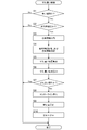
- FIG. 3 is a flowchart illustrating a flow of passing control executed by the vehicle driving support apparatus according to the first embodiment. It is explanatory drawing explaining the state before a 1st vehicle and a 2nd vehicle pass each other. It is explanatory drawing explaining the state when a 1st vehicle and a 2nd vehicle pass each other.
- the passing position prediction unit calculates an inter-vehicle distance between the first vehicle and the second vehicle before the first vehicle and the second vehicle pass each other.
- a first speed detector that detects the speed of the first vehicle
- a second speed detector that detects the speed of the second vehicle
- an inter-vehicle distance calculated by the inter-vehicle distance calculator and a first speed detector
- a position information calculation unit that calculates position information indicating a passing position based on the speed of the first vehicle detected by the unit and the speed of the second vehicle detected by the second speed detection unit. Good.
- the passing position prediction unit estimates the passing position after grasping the inter-vehicle distance between the first vehicle and the second vehicle, the speed of the first vehicle, and the speed of the second vehicle.
- the position where the vehicle and the second vehicle pass can be identified more accurately.
- the road width specifying unit and the approach amount calculation unit can more accurately calculate the road width at the passing position and the approach amount of the first vehicle.
- the first and second inventions are specified by the width of the first vehicle specified by the first width information acquired by the first width information acquisition unit and the second width information acquired by the second width information acquisition unit. Based on the width of the second vehicle, the passing position predicted by the passing position prediction unit, and the road width specified by the road width specifying unit, the first vehicle and the second vehicle are in a predetermined passable state at the passing position. You may have the determination part which determines whether or not.
- the notification unit may function to perform notification according to the determination result of the determination unit when it is determined that at least the determination unit is not in a predetermined passable state.
- the determination unit can more accurately determine whether or not the first vehicle and the second vehicle are in a predetermined passable state, and the notification unit can notify the result. it can.
- the notification unit can notify the result. It can.
- a notification to that effect is made, so that the driver who understands the notification can easily take an appropriate response.
- the first position detector is a distance from the first vehicle side width direction end portion on the road to the first vehicle before the first vehicle and the second vehicle pass each other. 1 It may function to detect the current width.
- the amount-of-shift calculation unit calculates the first vehicle based on a residual value obtained by subtracting the width of the first vehicle and the width of the second vehicle from the road width at the passing position and the first current width detected by the first position detection unit. It is also possible to function so as to calculate the amount of misalignment.
- the first position detection unit determines the first current width (the distance from the widthwise end on the first vehicle side on the road to the first vehicle). Can be detected. Then, the approach amount calculation unit more accurately grasps the distance between the road edge before passing the first vehicle and the first vehicle, and then the margin amount at the time of passing (the width of the first vehicle and the first vehicle from the road width at the passing position). The remaining amount of the first vehicle can be calculated more accurately based on the remaining value obtained by reducing the width of the two vehicles.
- a second position detection unit that detects a current position in the width direction of the second vehicle on the road and a first width information acquisition unit acquired before the first vehicle and the second vehicle pass each other.
- the width of the first vehicle specified by the first width information, the width of the second vehicle specified by the second width information acquired by the second width information acquisition unit, and the second vehicle detected by the second position detection unit A second shift amount calculation unit that calculates the shift amount of the second vehicle based on the current position in the width direction, the passing position predicted by the passing position prediction unit, and the road width specified by the road width specifying unit;
- at least the second vehicle may have a second notification unit that notifies the approach amount of the second vehicle.
- the situation of the second vehicle at the time of passing (especially the position in the width direction) Can be guessed. And if such information (information that can grasp the situation of the second vehicle at the time of passing) and the current position in the width direction of the second vehicle detected by the second position detection unit are obtained, An amount indicating how much the second vehicle should be approached between the passing positions (the amount of approach of the second vehicle) can be calculated more accurately. As a result, such an approach amount is calculated by the driver in the second vehicle. Can be notified.
- the second position detection unit is a second current width that is a distance from the width direction end of the road on the second vehicle side to the second vehicle before the first vehicle and the second vehicle pass each other. May function to detect.
- the second shift amount calculation unit calculates the first value based on the remaining value obtained by subtracting the width of the first vehicle and the width of the second vehicle from the road width at the passing position and the second current width detected by the second position detection unit. It may function to calculate the approach amount of the two vehicles.
- the second position detection unit determines the second current width (the distance from the widthwise end on the second vehicle side on the road to the second vehicle). Can be detected. Then, the second shift amount calculation unit more accurately grasps the distance between the road edge before the passing and the second vehicle, and then the margin at the time of passing (the width of the first vehicle from the road width at the passing position). And the remaining value obtained by reducing the width of the second vehicle), the amount of shift of the second vehicle can be calculated more accurately.
- the driving support system 1 shown in FIG. 1 has a configuration including a plurality of in-vehicle devices respectively mounted on a plurality of vehicles.
- the driving support system 1 including the driving support device 10 provided in the first vehicle 101 and the second support device 20 provided in the second vehicle 102 will be described as an example.
- the driving support system 1 is configured as a system that can support at least the driving of the first vehicle 101.
- the driving supporting system 1 is a system that supports driving of both the first vehicle 101 and the second vehicle 102. ing.
- one second vehicle 102 is representatively shown, but a plurality of similar second vehicles including the second support device 20 may exist.
- the driving support device 10 provided in the first vehicle 101 includes a control unit 11, a wireless communication unit 12, an inter-vehicle communication unit 13, a GPS communication unit 14, a storage unit 15, An imaging unit 16, a notification unit 17, and a vehicle speed sensor 18 are provided.
- the driving support device 10 may have a configuration including a single electronic control device or a configuration including a plurality of electronic control devices.
- the control unit 11 is configured as, for example, an information processing apparatus (for example, a microcomputer) including a CPU and a memory.
- the control unit 11 has a function of performing communication in cooperation with the wireless communication unit 12, the inter-vehicle communication unit 13, the GPS communication unit 14, and the like.
- the control unit 11 has a function of performing reading from the storage unit 15 and writing to the storage unit 15, a function of performing storage and analysis of an image obtained by imaging of the imaging unit 16, and a function of causing the notification unit 17 to perform a notification operation. And so on.
- the wireless communication unit 12 is a device that performs wireless communication with an external information device, and includes one or a plurality of communication devices.
- the wireless communication unit 12 may be configured to perform a wireless communication method with an external device according to any communication method, and a plurality of communication devices that can communicate with each communication method are provided to perform wireless communication with a plurality of communication methods.
- the structure to obtain may be sufficient.
- the radio communication unit 12 is, for example, LTE (Long Term Evolution) standard, IMT-2000 (International Mobile Telecommunication 2000) standard (so-called 3G communication standard), narrow area communication (DSRC) system standard, and other known radio communication standards. Wireless communication is performed with an external device using the wireless communication method defined in.
- the inter-vehicle communication unit 13 is configured as a device that performs known inter-vehicle communication with the second vehicle 102 located at a distance close to the first vehicle 101 (a distance at which the inter-vehicle communication unit 13 can communicate). .
- the inter-vehicle communication unit 13 can perform inter-vehicle communication with the inter-vehicle communication unit 23 mounted on the second vehicle 102, and can transmit information to the inter-vehicle communication unit 23 and receive information from the inter-vehicle communication unit 23. . Since it is configured to be communicable in this way, information held by the second vehicle 102 can be transmitted to the first vehicle 101, and conversely, information held by the first vehicle 101 is transmitted to the second vehicle 102. You can also
- the vehicle-to-vehicle communication method performed between the vehicle-to-vehicle communication unit 13 and the vehicle-to-vehicle communication unit 23 may be a known method capable of wireless communication.
- the inter-vehicle communication between the inter-vehicle communication unit 13 and the inter-vehicle communication unit 23 may be a method in which wireless communication is performed directly without interposing an external device.
- a method in which information is transmitted from the vehicle-to-vehicle communication unit 13 to the vehicle-to-vehicle communication unit 23 and a method in which information is transmitted from the vehicle-to-vehicle communication unit 23 to the vehicle-to-vehicle communication unit 13 via an external device may be used. .
- the GPS communication unit 14 is configured as a known GPS communication device that can communicate with the GPS satellite 30.
- the GPS communication part 14 acquires the positional information (GPS positional information) which specifies the position of the 1st vehicle 101 by communicating with the GPS satellite 30, for example.
- the control unit 11 functions as a position detection unit, and calculates the position (specifically, for example, latitude and longitude) of the first vehicle 101 based on the position information (GPS position information) acquired by the GPS communication unit 14. obtain.
- the storage unit 15 is configured by one or a plurality of types of storage devices, for example, a known semiconductor memory such as a ROM, a RAM, and a nonvolatile memory, or another storage device.
- a known semiconductor memory such as a ROM, a RAM, and a nonvolatile memory, or another storage device.
- the storage unit 15 stores map data that can identify the position of each road, each building, and the like in association with latitude and longitude, and constitutes a map database.
- the map database configured by the storage unit 15 is map data used in the car navigation system, and stores, for example, road map data all over Japan, facility data of various facilities and stores, etc. associated therewith.
- the road map data stored in the storage unit 15 includes road width data indicating the road width of each position in association with each position of the road. Specifically, for example, road map data is obtained by dividing a road existing in an area (map target area) that can be represented by road map data into a plurality of areas, and the road width for each area. The data is associated. That is, the road map data has a data configuration that can specify the road width of the position if the position of the road can be specified.
- the imaging unit 16 is configured as a known in-vehicle camera such as a CCD camera or a CMOS camera, and captures an image in a predetermined imaging range set outside the first vehicle 101.
- the imaging unit 16 is configured by one or a plurality of vehicle-mounted cameras, and at least one vehicle-mounted camera is disposed so as to capture the front side of the first vehicle 101. For example, when the first vehicle 101 is traveling along a straight road along the direction of the road, the first vehicle 101 can capture an image of the area ahead of the first vehicle 101 in the road.
- An imaging range is set in which an area on at least the front side and the lower side of 101 can be imaged.
- the notification unit 17 includes a sound generation device such as a speaker and a buzzer or a display device such as a lamp and a display unit, and functions to perform notification using sound, light, an image, and the like.
- the notification unit 17 has both a sounding device and a display device, and is configured to perform image display and voice notification.
- the vehicle speed sensor 18 is a known vehicle speed sensor that can detect the vehicle speed of the first vehicle 101.
- the vehicle speed sensor 18 outputs a signal indicating the vehicle speed of the first vehicle 101, and the control unit 11 grasps the speed of the first vehicle 101 based on the vehicle speed signal output from the vehicle speed sensor 18.
- the GPS (Global Positioning System) satellite 30 is a well-known GPS artificial satellite used in the GPS system, and actually there are a plurality of GPS satellites.
- each of the driving support device 10 and the second support device 20 can perform position specification (for example, specification of latitude and longitude) using a GPS system.
- the wireless communication device 40 is a base station, access point, or other wireless communication device installed outside the first vehicle 101 or the second vehicle 102, and the wireless communication unit 12 of the first vehicle 101 or the second vehicle 102, 22 is a device capable of performing wireless communication with 22.
- the control unit 11 and the notification unit 17 can function as a known navigation device.
- the position detection for the GPS communication unit 14, the control unit 11, the vehicle speed sensor 18, and the like to detect (position) the position of the host vehicle (first vehicle 101) based on the transmission radio wave from the GPS satellite 30.
- the position detector includes a gyro sensor that detects the rotational angular velocity of the host vehicle.
- the control unit 11 Based on the input from each sensor, the control unit 11 has a current position (absolute position), a traveling direction, a speed, a travel distance, and a current time of the host vehicle (first vehicle 101) based on input from each sensor. Etc. are detected with high accuracy.
- the control unit 11 is a display device that configures the notification unit 17 based on the current position of the host vehicle (first vehicle 101) specified by the function as the position detection unit and the map data obtained from the map database described above.
- a location function for displaying the current position (and the traveling direction) of the host vehicle together with the road map around the host vehicle on the screen can be realized.
- the second support device 20 provided in the second vehicle 102 includes a control unit 21, a wireless communication unit 22, an inter-vehicle communication unit 23, a GPS communication unit 24, and a storage unit 25.
- the imaging unit 26, the notification unit 27, and the vehicle speed sensor 28 are provided.
- the driving support device 10 may have a configuration including a single electronic control device or a configuration including a plurality of electronic control devices.
- the second support device 20 has the same configuration as the driving support device 10 in terms of hardware.
- control unit 21, the wireless communication unit 22, the inter-vehicle communication unit 23, the GPS communication unit 24, the storage unit 25, the imaging unit 26, the notification unit 27, and the vehicle speed sensor 28 constituting the second support device 20 10 has the same hardware configuration as each of the control unit 11, the wireless communication unit 12, the inter-vehicle communication unit 13, the GPS communication unit 14, the storage unit 15, the imaging unit 16, the notification unit 17, and the vehicle speed sensor 18. And the same functions (the above-mentioned functions of each device).
- FIG. 2 is a functional block diagram for explaining the relationship between the functions executed by the driving support system 1. Specifically, a functional block diagram regarding the linkage of the functions executed by the driving support device 10 and a functional block diagram of the linkage of the functions executed by the second support device 20 are shown.
- Each function executed in the driving support system 1 may be realized by software processing using an information processing apparatus, or may be realized by a hardware circuit.
- Each function may be realized by a separate device, and a plurality of functions may be realized by a common device.
- the first width information acquisition unit 53 is a part having a function of specifying the width of the first vehicle 101.
- the second width information acquisition unit 54 is a part having a function of acquiring second width information that specifies the width of the second vehicle 102 that is to be passed by the first vehicle 101.
- the first position detection unit 52 has a function of detecting the current position in the width direction of the first vehicle 101 on the road before the first vehicle 101 and the second vehicle 102 pass each other. Specifically, the first position detection unit 52 is a distance from the first vehicle 101 side to the first vehicle 101 on the road before the first vehicle 101 and the second vehicle 102 pass each other. It has a function of detecting the first current width.
- the passing position prediction unit 51 is a part having a function of predicting a passing position between the first vehicle 101 and the second vehicle 102 in the traveling direction of the first vehicle 101 on the road through which the first vehicle 101 and the second vehicle 102 pass. is there.
- the passing position prediction unit 51 includes an inter-vehicle distance calculation unit 51A, a first speed detection unit 51B, a second speed detection unit 51C, and a position information calculation unit 51D.
- the inter-vehicle distance calculation unit 51A is a part having a function of calculating the inter-vehicle distance between the first vehicle 101 and the second vehicle 102 before the first vehicle 101 and the second vehicle 102 pass each other.
- the first speed detector 51 ⁇ / b> B is a part having a function of detecting the speed of the first vehicle 101.
- the second speed detection unit 51 ⁇ / b> C is a part having a function of detecting the speed of the second vehicle 102.
- the position information calculation unit 51D is detected by the inter-vehicle distance calculated by the inter-vehicle distance calculation unit 51A, the speed of the first vehicle 101 detected by the first speed detection unit 51B, and the second speed detection unit 51C. Based on the speed of the second vehicle 102, the position information indicating the passing position is calculated.
- the road width specifying part 55 is a part having a function of specifying the road width at the passing position predicted by the passing position predicting part 51.
- the amount calculation unit 56 is specified by the width of the first vehicle 101 specified by the first width information acquired by the first width information acquisition unit 53 and the second width information acquired by the second width information acquisition unit 54.
- the determination unit 57 specifies the width of the first vehicle 101 specified by the first width information acquired by the first width information acquisition unit 53 and the second width information acquired by the second width information acquisition unit 54. Based on the width of the two vehicles 102, the passing position predicted by the passing position prediction unit 51, and the road width specified by the road width specifying unit 55, the first vehicle 101 and the second vehicle 102 pass a predetermined passing position at the passing position. It has a function of determining whether or not it becomes possible.
- the notification unit 17 notifies the amount of approach of the first vehicle 101 at least in the first vehicle 101 based on the calculation result by the approach amount calculation unit 56. Further, the notification unit 17 has a function of performing notification according to the determination result of the determination unit 57 when it is determined that at least the determination unit 57 cannot pass at the passing position.
- the second position detector 62 detects the current position in the width direction of the second vehicle on the road before the first vehicle 101 and the second vehicle 102 pass each other.
- the second shift amount calculation unit 66 includes the width of the first vehicle 101 specified by the first width information acquired by the first width information acquisition unit 53 and the second width information acquired by the second width information acquisition unit 54.
- the width of the second vehicle to be identified, the current position in the width direction of the second vehicle 102 detected by the second position detection unit 62, the passing position predicted by the passing position prediction unit 51, and the road width specifying unit 55 Based on the identified road width, the approach amount of the second vehicle 102 is calculated.
- the second notification unit 27 functions to notify at least the amount of movement of the second vehicle 102 in the second vehicle 102 based on the calculation result by the second amount of movement calculation unit 66.
- the control unit 11 determines whether or not the road on which the first vehicle 101 is passing is a narrow road having a width less than a predetermined width (step S1).
- the control unit 11 specifies the current position (latitude and longitude) on the map of the first vehicle 101 based on the communication result made by the GPS communication unit 14 at the time of execution of step S1, for example. And based on the above-mentioned road map data memorized by storage part 15, it is within a fixed range in the advancing direction of the 1st vehicle 101 from the specified present position (position of the 1st vehicle 101 at the time of execution of Step S1). Check the road width.
- the control unit 11 includes a road less than a predetermined value within a certain range from the current position of the identified first vehicle 101 (the position of the first vehicle 101 at the time of execution of step S1). It is determined whether or not it exists. If it does not exist (No in step S1), it is determined in step S1 that the road is not a narrow road, and the control in FIG. 3 ends. That is, when the nearest road to which the first vehicle 101 is going to pass is wide to some extent, the control in FIG. 1 is terminated without performing the assist control executed in step S10 or the like.
- step S1 when there is a road less than a predetermined value within a certain range from the current position identified at the time of step S1 (when the result is Yes in step S1), the control unit 11 is about to pass the first vehicle 101 from now on. If the nearest road is narrow, it is determined in step S2 whether an oncoming vehicle (second vehicle 102) is approaching in front of the first vehicle 101.
- step S ⁇ b> 2 for example, the approach of the second vehicle 102 is determined by determining whether or not the vehicle-to-vehicle communication unit 23 of the second vehicle 102 exists in a range in which the vehicle-to-vehicle communication unit 13 can communicate.
- control unit 11 attempts to communicate with the inter-vehicle communication unit 23 of the second vehicle 102 by the inter-vehicle communication unit 13 and communication between the inter-vehicle communication unit 13 and the inter-vehicle communication unit 23 is established.
- step S2 it is determined that the second vehicle 102 is approaching, the process proceeds to Yes in step S2, and the process of step S3 is executed.
- step S3 the process of step S3 is executed.
- the vehicle When determining whether or not the second vehicle 102 is approaching the front of the first vehicle 101 by such a method, the vehicle is configured such that a communication area of a predetermined range is configured on the front side of the first vehicle 101. It is desirable that the inter-vehicle communication unit 13 is configured, and similarly, the inter-vehicle communication unit 23 is configured so that a predetermined range of communication area is configured on the front side of the second vehicle 102.
- the image is captured by the imaging unit 16 provided in the first vehicle 101.
- the approach of the second vehicle 102 may be determined based on the image.
- the image captured by the imaging unit 16 at the time of step S2 is analyzed to identify a road area and an object area located on the road, and an object having a predetermined width on the road (the ratio of the object width to the road area) May be determined that the second vehicle 102 is approaching, and if not, it may be determined that the second vehicle 102 is not approaching.
- the first vehicle 101 may be provided with a millimeter wave radar, a laser radar, or the like, and it may be determined by this device whether or not the second vehicle 102 exists within a predetermined range in front of the first vehicle 101.
- the control unit 11 determines in step S2 that the second vehicle 102 is approaching and proceeds to step S3, the control unit 11 acquires own vehicle information (that is, information on the first vehicle 101). For example, width information indicating the width of the first vehicle 101, information indicating the position P1 of the first vehicle 101, and information indicating the speed of the first vehicle 101 are acquired.
- the storage unit 15 stores first width information for specifying the width Wa of the first vehicle 101, and the control unit 11 reads the first width information from the storage unit 15 to obtain the first width information. To do.
- Information indicating the position P1 of the first vehicle 101 (information such as latitude and longitude indicating the current position of the first vehicle 101) is acquired by the function as the position detection unit described above.
- the control unit 11 causes the width Wa (vehicle width) of the first vehicle 101, the current position of the first vehicle 101 at the time of step S3, and the first at the time of step S3.
- the speed Va of the vehicle 101 can be specified.
- control unit 11 functions as an example of the first width information acquisition unit 53 and has a function of acquiring first width information that specifies the width of the first vehicle 101.
- the control unit 11 identifies the current position P1 of the first vehicle 101 by executing step S3. At this time, the distance from the end in the width direction on the first vehicle 101 side to the first vehicle 101 on the road (the width of the road). The first current width Da, which is the direction distance), is detected.
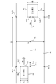
- the example of FIG. 4 conceptually shows the situation of the first vehicle 101 when the control unit 11 executes the process of step S3.
- the position P ⁇ b> 1 of the first vehicle 101 in the example of FIG. 4, the position of the center in the width direction at the front end of the first vehicle 101
- step S ⁇ b> 3 The position Pr1 closest to the position P1 is specified on the center line Lc of the road Rd specified from the road map data.
- the road map data includes data specifying the position of the center line Lc of the road Rd and data specifying the road width at each position of the center line Lc.
- the direction perpendicular to the direction Fr of the road Rd at the position Pr1 is defined as the width direction of the road Rd, and both end positions in the width direction of the position Pr1 on the road Rd (in the example of FIG. 4, the direction Pr1 and the direction perpendicular to the direction Fr).
- each position on the road end where the straight line passes is specified.
- each of Pr12 becomes both ends in the width direction of the road Rd at the position Pr1, and both ends in the width direction of the road Rd at the position P1.
- the control unit 11 sets the position Pr11 (position close to the position P1) on the side (left side) on which the first vehicle 101 is approached among the positions Pr11 and Pr12 specified in this way to the width on the first vehicle 101 side.
- a position Pc1 advanced by Wa / 2 toward the position Pr11 in the direction orthogonal to the direction of Fr from the position P1 as a direction end is defined as a width direction end position (left end position) on the position Pr11 side in the first vehicle 101, and Fr A distance Da between the position Pr11 and the position Pc1 in a direction orthogonal to the direction of is obtained. This distance Da is the first current width.
- the control unit 11 functions as an example of the first position detection unit 52.
- the control unit 11 has a function of detecting the current position in the width direction of the first vehicle 101 on the road Rd before the first vehicle 101 and the second vehicle 102 pass each other.
- the first current width Da which is the distance from the width direction end portion Pr11 on the one vehicle 101 side to the first vehicle 101 (specifically, the distance in the width direction to the width direction end portion Pc1) is detected.
- step S4 after step S3, the controller 11 determines the width Wa (vehicle width) of the first vehicle 101 acquired in step S3, the current position P1 of the first vehicle 101 at the time of step S3, and the time of step S3.
- Each information of the speed Va of the first vehicle 101 is transmitted to the second vehicle 102. This information transmission is performed by wireless communication between the inter-vehicle communication unit 13 and the inter-vehicle communication unit 23.
- control of the 2nd vehicle 102 used as an oncoming vehicle is demonstrated.
- the control in FIG. 3 is executed and the processes in steps S1 to S3 are performed.
- the second vehicle 102 the same control as in FIG. 3 is executed.
- the control unit 21 of the second vehicle 102 repeatedly executes the same control as in FIG. 3 during the operation of the vehicle.
- the determination process (first process) similar to step S1 is performed, and the second vehicle It is determined whether or not the road through which the road 102 passes is a narrow road having a width less than a predetermined width. If it is determined in the first process that the road is narrow, that is, if the answer is Yes, the same determination process (second process) as in step S2 is executed.
- step S3 it is determined whether an oncoming vehicle (for example, the first vehicle 101 in the case of FIG. 4) is approaching in the same manner as the first vehicle 101, and the oncoming vehicle (first vehicle 101) is determined. ) Is approaching, that is, when the answer is Yes, the same acquisition process (third process) as in step S3 is performed to acquire information on the own vehicle (second vehicle 102).
- an oncoming vehicle for example, the first vehicle 101 in the case of FIG. 4
- the width information indicating the width Wb of the second vehicle 102 and the position P2 of the second vehicle 102 And information indicating the speed Vb of the second vehicle 102 are acquired.
- the storage unit 25 stores second width information for specifying the width Wb of the second vehicle 102, and the control unit 21 reads out the second width information from the storage unit 25.
- Information indicating the position P ⁇ b> 2 of the second vehicle 102 (information such as latitude and longitude indicating the current position of the second vehicle 102) is acquired by a function as a position detection unit provided similarly to the first vehicle 101.
- the control unit 21 executes the third process similar to step S3, whereby the width Wb (vehicle width) of the second vehicle 102 and the current position P2 of the second vehicle 102 at the time when the third process is performed (see FIG. In the example of FIG. 4, the speed Vb of the second vehicle 102 at the time when the third process is performed can be specified. Then, the position Pr2 on the center line Lc closest to the position P2 in the center line Lc of the road Rd specified by the road map data is specified by a method similar to the method performed by the first vehicle 101 in step S3. The width direction both ends Pr21 and Pr22 of the road Rd at Pr2 are specified.
- the left end portion Pc2 in the second vehicle 102 is specified by the same method as that performed by the first vehicle 101 in step S3, and the distance Db between Pc2 and Pr22 is set to the width on the second vehicle 102 side on the road Rd. It is detected as the second current width that is the distance from the direction end to the second vehicle 102.
- the control unit 21 of the second vehicle 102 performs the third process similar to step S3, then performs the same process (fourth process) as step S4, and obtains the width Wb of the second vehicle 102 acquired in the third process.
- Vehicle width each piece of information specifying the current position P2 of the second vehicle 102 at the time of the third process and the speed Vb of the second vehicle 102 at the time of the third process is transmitted to the first vehicle 101. To do.
- This information transmission is performed by wireless communication between the inter-vehicle communication unit 13 and the inter-vehicle communication unit 23.
- the information including the width Wb (vehicle width) of the second vehicle 102, the current position P2 of the second vehicle 102, and the speed Vb of the second vehicle 102 is wirelessly transmitted from the second vehicle 102.
- the control unit 11 of the vehicle 101 acquires this information in step S4.
- information including the width Wa (vehicle width) of the first vehicle 101, the current position P1 of the first vehicle 101, and the speed Va of the first vehicle 101 is also transmitted wirelessly from the first vehicle 101.
- the control unit 21 of the vehicle 102 acquires this information by the same process (fourth process) as in step S4.
- control unit 11 and the vehicle-to-vehicle communication unit 13 function as an example of the second width information acquisition unit 54, and the second width information that specifies the width Wb of the second vehicle 102 that is to be passed by the first vehicle 101. It functions to acquire by the vehicle-to-vehicle communication.
- the imaging unit 16 captures images of the second vehicle 102 and the road Rd at the same time, obtains a ratio of the width of the second vehicle 102 to the width of the road Rd in the captured image, and at the position P1 detected by the position detection unit.
- a value obtained by multiplying the above ratio by the road width may be used as the width Wb of the second vehicle 102.
- the width of the second vehicle 102 may be obtained by scanning the second vehicle 102 with the laser radar.
- control part 11 and the vehicle-to-vehicle communication part 13 function as an example of the 2nd speed detection part 51C, and the function which detects the speed of the 2nd vehicle 102 (specifically acquired by vehicle-to-vehicle communication).
- a 2nd speed detection part is not limited to this example.
- a known speed detection device that detects the speed of an external object specifically, a known device that can detect the speed of an object approaching oppositely
- the speed Vb of the second vehicle 102 may be detected.
- the passing position Px is a position on the center line Lc of the road Rd. At the time of passing, the passing position Px is on a straight line passing through the position Px (direction orthogonal to the road direction at the position Px) as shown in FIG.
- the position P1 of the first vehicle 101 and the position P2 of the second vehicle 102 are located.
- control unit 11 and the vehicle speed sensor 18 function as an example of the passing position prediction unit 51, and the first vehicle 101 in the traveling direction of the first vehicle 101 on the road Rd through which the first vehicle 101 and the second vehicle 102 pass.
- the second vehicle 102 have a function of predicting a passing position Px.
- the control unit 11 functions as an example of the inter-vehicle distance calculation unit 51A, and the vehicle between the first vehicle 101 and the second vehicle 102 before the first vehicle 101 and the second vehicle 102 pass each other.
- the distance D is calculated.
- the control unit 11 functions as an example of the position information calculation unit 51D.
- position information indicating the passing position Px is calculated based on the speed Vb of the second vehicle 102 detected by the second speed detector 51C.
- the information on the time S and the distance L is position information indicating the passing position Px.
- Dz threshold value for which a margin width is determined
- control unit 11 functions as an example of the road width specifying unit 55, and has a function of specifying the road width Wx at the passing position Px predicted by the passing position predicting unit 51.
- control unit 11 functions as an example of the determination unit 57, and the width Wa of the first vehicle 101 specified by the first width information acquired by the first width information acquisition unit 53 and the second width information acquisition unit
- the width Wb of the second vehicle 102 specified by the acquired second width information, the passing position Px predicted by the passing position prediction unit, and the road width specified by the road width specifying unit 55 (the road width at the passing position Px) Wx) whether or not the first vehicle 101 and the second vehicle 102 are in a predetermined passable state at the pass position Px (specifically, a pass state in which a surplus width equal to or greater than the surplus width Dz is secured) Or not).
- the notification unit 17 may function to perform notification according to the determination result of the determination unit. For example, a warning message such as “It is difficult to pass” may be displayed on the display device, or a sound may be emitted. The value of the buzzer ringing with a predetermined ringing method and the lamp with a predetermined display method are displayed. May be.
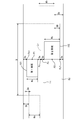
- step S8 the virtual line in the width direction passing the passing position Px.
- a center position Pc (a virtual center line position considering the width size) in consideration of the width size of the first vehicle 101 and the second vehicle 102 is calculated.
- Dc Wx ⁇ (Wa + Wb) when the remainder obtained by removing the widths Wa and Wb of both vehicles from the road width Wx is Dc.
- Dx Dc / 4 where Dx is the allocation to each position.
- the center position Pc in consideration of the width of both vehicles at the passing position Px (virtual center line in consideration of the width size) has a relationship as shown in FIG.
- the width is Wa + 2 ⁇ Dx.
- the width from the road edge to the center position Pc is Wb + 2 ⁇ Dx.
- the left justification amount DB of the second vehicle 102 may be transmitted to the second vehicle by inter-vehicle communication between the inter-vehicle communication unit 13 and the inter-vehicle communication unit 23.
- control unit 11 functions as an example of the approach amount calculation unit 56, and the width Wa of the first vehicle 101 specified by the first width information acquired by the first width information acquisition unit and the second width information acquisition.
- the width Wb of the second vehicle 102 specified by the second width information acquired by the unit, the current position in the width direction of the first vehicle 101 detected by the first position detection unit, and the passing position predicted by the passing position prediction unit Based on Px and the road width Wx specified by the road width specifying unit, it has a function of calculating the approach amount DA of the first vehicle 101.
- the control part 11 makes the alerting
- the notification unit 17 is notified so that the driver can recognize the calculated amount DA of the first vehicle 101. For example, a message such as “Please move the vehicle to the left by the amount of approach DA” may be displayed on the display device mounted on the first vehicle 101, and such a message may be notified by voice.
- the notification unit 17 functions to notify the approach amount DA of the first vehicle 101 in the first vehicle 101 based on the calculation result by the approach amount calculation unit.
- the control executed by the second vehicle 102 will be described in more detail.
- the control unit 21 of the second vehicle 102 performs the same control as FIG. 3 in the same flow as FIG.
- the oncoming vehicle (communication partner) when the second vehicle 102 performs the same control as in FIG. 3 is the first vehicle 101.
- the flow in the case where the control unit 21 of the second vehicle 102 performs the same processing (first to fourth processing) as steps S1 to S4 is as described above.
- the control unit 21 of the second vehicle 102 performs the same process (first process to fourth process) as steps S1 to S4 shown in FIG. 3, and then performs the same process (fifth process) as step S5.
- the passing position Px is calculated by the same method as the control unit 11 of one vehicle 101.
- the control unit 21 can function as a passing position prediction unit.
- the control unit 21 calculates the passing position Px in the same process (fifth process) as in step S5, and then performs the same process (sixth process) as in step S6 to estimate the passing situation. Specifically, the control unit 21 obtains the surplus width Dy by the same method as the control unit 11 in the sixth process, and then performs the seventh process similar to step S7, and sets a predetermined threshold Dz (allowance width). And Dy ⁇ Dz to determine whether or not Dy ⁇ Dz. If Dy ⁇ Dz, it is determined that it is difficult to pass each other, the process proceeds to Yes in the seventh process, and the same control as in FIG. When the control unit 21 determines that the passing is difficult in the seventh process, the control unit 21 may cause the notification unit 27 to perform a notification operation.
- a warning message such as “passing is difficult” is displayed. It may be displayed on the apparatus or may emit a sound, or a value obtained by ringing a buzzer with a predetermined ringing method or a lamp with a predetermined display method may be displayed.
- step S8 the process similar to step S8 (eighth process) And the center position Pc (the position of the virtual center line in consideration of the width size) is calculated by the same method as the control unit 11. Then, after the eighth process, the control unit 21 performs the same process as the step S9 (the ninth process), and calculates the left justification amount DA of the first vehicle 101 and the left justification amount DB of the second vehicle 102.
- the left justification amount DB of 102 is calculated.
- the left justification amount DA of the first vehicle 101 may be transmitted to the first vehicle 101 by inter-vehicle communication between the inter-vehicle communication unit 13 and the inter-vehicle communication unit 23.
- control unit 21 functions as an example of the second position detection unit 62, and the current position of the second vehicle 102 is the same as the method in which the first position detection unit 52 detects the current position of the first vehicle 101. Detect position.
- the second position detection unit 62 has a function of detecting the current position in the width direction of the first vehicle 101 on the road Rd before the first vehicle 101 and the second vehicle 102 pass each other.
- the distance from the width direction end portion Pr22 on the second vehicle 102 side to the second vehicle 102 on the road Rd (specifically, the distance in the width direction to the width direction end portion Pc2) is the second.
- the current width Db is detected.
- control part 21 functions as an example of the 2nd approach amount calculation part 66,
- the width Wa of the 1st vehicle 101 specified by the 1st width information which the 1st width information acquisition part 53 acquired, and 2nd width information The width Wb of the second vehicle 102 specified by the second width information acquired by the acquisition unit 54, the current position in the width direction of the second vehicle 102 detected by the second position detection unit 62, and the passing position prediction unit 51
- the approach amount DB of the second vehicle 102 is calculated.
- the control unit 21 When the control unit 21 is caused to function as an example of the second shift amount calculation unit 66, the width Wa of the first vehicle 101 specified by the first width information acquired by the first width information acquisition unit 53, the second width information acquisition unit For the width Wb of the second vehicle 102 specified by the second width information acquired by 54, the passing position Px predicted by the passing position prediction unit 51, and the road width Wx specified by the road width specifying unit 55, the first vehicle The control unit 21 may acquire the information by inter-vehicle communication between the 101 and the second vehicle 102. Alternatively, the second vehicle 102 is provided with portions that function in the same manner as the first width information acquisition unit 53, the second width information acquisition unit 54, the road width specification unit 55, and the passing position prediction unit 51. The width Wa of the first vehicle 101, the width Wb of the second vehicle 102, the passing position Px, and the road width Wx may be uniquely known.
- the control unit 21 After performing the ninth process, the control unit 21 performs the same process as the step S10 (tenth process) and causes the notification unit 27 to perform a notification operation.
- the notification unit 27 notifies the amount of shift of the second vehicle 102 in the second vehicle 102 based on the calculation result by the second shift amount calculation unit obtained in the ninth process.
- the notification unit 27 may display a message such as “Please move the vehicle to the left by the shift amount DB” on the display device mounted on the second vehicle 102, and such a message may be displayed. You may alert
- the driving support system 1 and the driving support device 10 are configured such that the width Wa of the first vehicle 101 specified by the first width information acquired by the first width information acquisition unit 53 and the second width information acquired by the second width information acquisition unit 54.
- the approach amount calculating unit 56 calculates the approach amount DA of the first vehicle 101.
- the situation of the first vehicle 101 when passing each other can be estimated. And if such information (information that can grasp the situation of the first vehicle 101 at the time of passing) and the current position in the width direction of the first vehicle 101 detected by the first position detection unit 52 are obtained, An amount indicating how much the first vehicle 101 should be approached from the current position to the passing position (the amount of approach of the first vehicle 101) can be calculated more accurately. The driver can be notified in one vehicle 101.
- the passing position prediction unit includes an inter-vehicle distance calculation unit 51A that calculates an inter-vehicle distance D between the first vehicle 101 and the second vehicle 102 before the first vehicle 101 and the second vehicle 102 pass each other.
- 1st speed detection part 51B which detects speed Va of 1 vehicle 101
- 2nd speed detection part 51C which detects speed Vb of 2nd vehicle 102
- distance D between vehicles computed by distance calculation part 51A between vehicles
- the position information indicating the passing position is calculated based on the speed Va of the first vehicle 101 detected by the first speed detection unit 51B and the speed Vb of the second vehicle 102 detected by the second speed detection unit 51C.
- Position information calculation unit 51D Position information calculation unit 51D.
- the passing position prediction unit recognizes the inter-vehicle distance D between the first vehicle 101 and the second vehicle 102, the speed Va of the first vehicle 101, and the speed Vb of the second vehicle 102, and then the passing position. Since Px is estimated, the position where the first vehicle 101 and the second vehicle 102 pass each other can be specified more accurately. As a result, the road width specifying unit 55 and the approach amount calculation unit 56 can more accurately calculate the road width at the passing position and the approach amount of the first vehicle 101.
- the driving support system 1 and the driving support device 10 are configured such that the width Wa of the first vehicle 101 specified by the first width information acquired by the first width information acquisition unit 53 and the second width information acquired by the second width information acquisition unit 54. Based on the width Wb of the second vehicle 102 specified by the width information, the passing position Px predicted by the passing position prediction unit 51, and the road width Wx specified by the road width specifying unit 55, the first vehicle 101 at the passing position. And the second vehicle 102 include a determination unit 57 that determines whether or not a predetermined passing state is possible.
- the notification unit 17 functions to perform notification according to the determination result of the determination unit 57 when at least the determination unit 57 determines that the predetermined passing state is not possible.
- the determination unit 57 more accurately determines whether or not the first vehicle 101 and the second vehicle 102 are in a predetermined passable state.
- the notification unit 17 can notify the result. When it is not in a predetermined passable state, a notification to that effect is made, so that the driver who understands the notification can easily take an appropriate response.
- the first position detector 52 is a first current width that is a distance from the width direction end portion Pr11 on the road toward the first vehicle 101 before the first vehicle 101 and the second vehicle 102 pass each other. It functions to detect Da.
- the amount-of-shift calculation unit 56 calculates the remaining value Dc obtained by subtracting the width Wa of the first vehicle 101 and the width Wb of the second vehicle 102 from the road width Wx at the passing position Px and the first current detected by the first position detection unit. It functions to calculate the approach amount DA of the first vehicle 101 based on the width Da.
- the first position detection unit 52 has the first current width Da (on the road toward the first vehicle 101 side). The distance from the end in the width direction to the first vehicle 101) can be detected. Then, the approach amount calculation unit 56 grasps the distance between the road end before passing each other and the first vehicle 101 more accurately, and then determines the first vehicle from the surplus amount at the time of passing (the road width Wx at the passing position Px). Based on the remaining value Dc) obtained by subtracting the width Wa of 101 and the width Wb of the second vehicle 102, the shift amount DA of the first vehicle 101 can be calculated more accurately.
- the driving support system 1 includes a second position detection unit 62 that detects a current position in the width direction of the second vehicle 102 on the road before the first vehicle 101 and the second vehicle 102 pass each other, and a first width information acquisition unit. 53, the width Wa of the first vehicle 101 specified by the first width information acquired by 53, the width Wb of the second vehicle 102 specified by the second width information acquired by the second width information acquisition unit 54, and the second Based on the current position in the width direction of the second vehicle 102 detected by the position detection unit 62, the passing position Px predicted by the passing position prediction unit 51, and the road width Wx specified by the road width specifying unit 55, the second vehicle
- the second approach amount calculation unit 66 that calculates the approach amount DB of 102, and the notification unit 27 (notifying the approach amount of the second vehicle 102 at least in the second vehicle 102 based on the calculation result by the second approach amount calculation unit 66) Second notification part) That.
- the second vehicle 102 at the time of passing The situation (especially the position in the width direction) can be estimated. And if such information (information that can grasp the situation of the second vehicle 102 at the time of passing) and the current position in the width direction of the second vehicle 102 detected by the second position detection unit 62 are obtained, An amount indicating how much the second vehicle 102 should be approached from the current position to the passing position (the approach amount DB of the second vehicle 102) can be calculated more accurately. As a result, such an approach amount DB Can be notified to the driver in the second vehicle 102.
- the second position detection unit 62 has a second current width that is a distance from the width direction end portion Pr22 on the second vehicle 102 side to the second vehicle 102 on the road before the first vehicle 101 and the second vehicle 102 pass each other. It functions to detect Db.
- the second shift amount calculating unit 66 detects the residual value Dc obtained by subtracting the width Wa of the first vehicle 101 and the width Wb of the second vehicle 102 from the road width Wx at the passing position Px and the second position detecting unit. It functions to calculate the approach amount DB of the second vehicle 102 based on the 2 current width Db.
- the second position detection unit detects the second current width Db (the width of the road on the second vehicle 102 side). The distance from the direction end to the second vehicle 102) can be detected. Then, the second shift amount calculating unit 66 more accurately grasps the distance between the road end before passing and the second vehicle 102, and then obtains the surplus amount at the time of passing (from the road width Wx at the passing position Px). Based on the remaining value Dc) obtained by subtracting the width Wa of the first vehicle 101 and the width Wb of the second vehicle 102, the shift amount DB of the second vehicle 102 can be calculated more accurately.
- the wireless communication unit 12 and the inter-vehicle communication unit 13 are configured as separate devices, but they may be shared. That is, the wireless communication unit 12 may perform wireless communication (vehicle-to-vehicle communication) with the wireless communication unit 22 or the vehicle-to-vehicle communication unit 23 of the second vehicle 102 directly or indirectly through an external device.
- the vehicle speed sensor 18 is illustrated as an example of the first speed detection unit, but the present invention is not limited to this example as long as the apparatus can detect a value reflecting the speed of the first vehicle 101.
- the 1st speed detection part may be comprised by the wheel speed sensor, the acceleration sensor, etc.
- the vehicle speed sensor 18 may function as the first speed detecting unit, and when the speed of the second vehicle 102 is grasped in the second vehicle 102, The control unit 21 and the inter-vehicle communication unit 23 of the two vehicles 102 can function as a first speed detection unit (a portion that acquires the speed information detected by the vehicle speed sensor 18 from the first vehicle 101).
- the vehicle speed sensor 28 may function as the second speed detecting unit, and when grasping the speed of the second vehicle 102 in the first vehicle 101, the control unit 11 and the inter-vehicle communication unit 13 of the first vehicle 101 can function as a second speed detection unit (a portion that acquires the speed information detected by the vehicle speed sensor 28 from the second vehicle 102).
- assist that assumes that the second vehicle 102 moves to the left in cooperation is illustrated, but assist that assumes that the second vehicle 102 does not cooperate may be performed.
- the distance Db from the current position P2 of the second vehicle 102 and the width Wb of the second vehicle 102 acquired in step S4 of FIG. 3 to the road edge of the second vehicle 102 is grasped, and the above-described Db is maintained when passing each other. You may perform the assistance supposing that it remains.
- the method based on the GPS information is illustrated as a method for the control unit 11 to grasp the current position of the first vehicle 101 in the width direction of the road Rd.
- the road is detected by a camera mounted on the first vehicle 101.
- the current position in the width direction of the first vehicle 101 on the road may be grasped from the captured image. That is, the right end position of the left end position of the road in the image to be captured changes depending on the position of the first vehicle 101 in the width direction, so that the ratio of the position of the first vehicle 101 in the road can be grasped. May be.
- the width Da between the left end portion of the first vehicle 101 and the end portion of the road may be grasped based on the road width at the current position grasped from the road map data.
- the first vehicle 101 to grasp the current position of the second vehicle 102 a method for acquiring information by inter-vehicle communication has been described.
- a road mounted by a camera mounted on the first vehicle 101 is used.
- the second vehicle 102 may be imaged, and the current position in the width direction of the second vehicle 102 on the road (specifically, the value Db) may be grasped from the captured image.
- the distance D from the first vehicle 101 to the second vehicle 102 is obtained by a known distance measuring device to grasp the position P2 of the second vehicle 102, and the position P2 of the second vehicle 102 is determined based on the road map data.
- the road width is specified, the actual width of the road region can be obtained in an image obtained by imaging the road and the second vehicle 102, and the actual width between the second vehicle 102 and the road edge (ie, Db ) Can also be requested.
Abstract
In order to more accurately provide notification of the pullover amount of a vehicle before the vehicle passes, in this driving assistance system (1) a pullover amount calculation unit (56) calculates the pullover amount of a first vehicle (101) on the basis of the width of the first vehicle (101), the width of a second vehicle (102), the current position of the first vehicle (101) in the width direction as detected by a first position detection unit (52), a passing position predicted by a passing position prediction unit (51), and the road width at the passing position as identified by a road width identification unit (55). On the basis of a calculation result from the pullover amount calculation unit (56), a notification unit (17) notifies at least the first vehicle (101) of the pullover amount of the first vehicle (101).
Description
本発明は、運転支援システム及び運転支援装置に関するものである。
The present invention relates to a driving support system and a driving support device.
特許文献1には、車両がすれ違う際の走行を支援する車両用走行支援装置が開示されている。この車両用走行支援装置は、対向車と自車とのすれ違い位置を予測し、予測すれ違い位置における道幅から対向車の幅を減じた第1道幅残量を算出する。更に、道幅から対向車の幅を減じた第2道幅残量が、自車と対向車とがゆとりをもってすれ違うことができるゆとり幅以上である位置(予備すれ違い位置)を予測すれ違い位置より自車側で検出する。そして、自車と対向車とがすれ違う際に注意が必要な注意幅よりも第1道幅残量が小さく且つ予備すれ違い位置が検出された場合、予備すれ違い位置ですれ違うように第2走行支援制御を行う。
Patent Document 1 discloses a vehicular driving support device that supports driving when vehicles pass each other. The vehicular travel support apparatus predicts a passing position between the oncoming vehicle and the host vehicle, and calculates a first road width remaining amount obtained by subtracting the width of the oncoming vehicle from the road width at the predicted passing position. Furthermore, predict the position where the remaining width of the second road, which is the width of the oncoming vehicle minus the width of the oncoming vehicle, is more than the clearance width that allows the own vehicle and the oncoming vehicle to pass each other with a margin (preliminary passing position). Detect with. When the first road width remaining amount is smaller than the caution width that requires attention when the vehicle and the oncoming vehicle pass each other, and the preliminary passing position is detected, the second driving support control is performed so that the preliminary passing position is passed. Do.
特許文献1で開示される走行支援装置は、予測すれ違い位置においてすれ違いが難しいか否かを判断し、難しい場合には車両を減速させてより広い位置ですれ違いがなされるように減速制御を行うものである。しかし、この技術は、進行方向の位置を調整するという思想のみが存在し、幅方向を細かくアシストするという思想が存在しない。このため、すれ違いの際に車両をどの程度寄せるべきかを運転者が把握しにくいという問題がある。
The driving support device disclosed in Patent Document 1 determines whether or not passing is difficult at a predicted passing position, and if it is difficult, decelerates the vehicle to perform deceleration control so that the passing is performed at a wider position. It is. However, this technique has only the idea of adjusting the position in the traveling direction, and does not have the idea of finely assisting in the width direction. For this reason, there is a problem that it is difficult for the driver to know how much the vehicle should be approached when passing each other.
本発明は上述した事情に基づいてなされたものであり、車両がすれ違う前に車両の寄せ量をより正確に報知することを目的とするものである。
The present invention has been made based on the above-described circumstances, and has an object of more accurately informing the amount of vehicle approach before the vehicles pass each other.
第1の発明の運転支援システムは、
第1車両の幅を特定する第1幅情報を取得する第1幅情報取得部と、
前記第1車両とすれ違う対象となる第2車両の幅を特定する第2幅情報を取得する第2幅情報取得部と、
前記第1車両及び前記第2車両が通る道路において、前記第1車両の進行方向における前記第1車両と前記第2車両とのすれ違い位置を予測するすれ違い位置予測部と、
前記第1車両と前記第2車両とがすれ違う前に、前記道路における前記第1車両の幅方向の現在位置を検出する第1位置検出部と、
前記すれ違い位置予測部が予測した前記すれ違い位置における道路幅を特定する道路幅特定部と、
前記第1幅情報取得部が取得した前記第1幅情報で特定される前記第1車両の幅と、前記第2幅情報取得部が取得した前記第2幅情報で特定される前記第2車両の幅と、前記第1位置検出部が検出した前記第1車両の幅方向の現在位置と、前記すれ違い位置予測部が予測した前記すれ違い位置と、前記道路幅特定部が特定した前記道路幅とに基づき、前記第1車両の寄せ量を算出する寄せ量算出部と、
前記寄せ量算出部による算出結果に基づき、少なくとも前記第1車両において前記第1車両の寄せ量を報知する報知部と、
を有する。 The driving support system of the first invention comprises:
A first width information acquisition unit for acquiring first width information for specifying a width of the first vehicle;
A second width information acquisition unit for acquiring second width information for specifying a width of the second vehicle to be passed by the first vehicle;
A passing position prediction unit that predicts a passing position between the first vehicle and the second vehicle in the traveling direction of the first vehicle on a road through which the first vehicle and the second vehicle pass;
A first position detecting unit that detects a current position of the first vehicle in the width direction on the road before the first vehicle and the second vehicle pass each other;
A road width specifying unit for specifying a road width at the passing position predicted by the passing position prediction unit;
The width of the first vehicle specified by the first width information acquired by the first width information acquisition unit and the second vehicle specified by the second width information acquired by the second width information acquisition unit The current position in the width direction of the first vehicle detected by the first position detection unit, the passing position predicted by the passing position prediction unit, and the road width specified by the road width specifying unit Based on, the approach amount calculation unit for calculating the approach amount of the first vehicle,
Based on the calculation result by the amount calculation unit, at least a notification unit for notifying the amount of movement of the first vehicle in the first vehicle;
Have
第2の発明の運転支援装置は、
第1車両の幅を特定する第1幅情報を取得する第1幅情報取得部と、
前記第1車両とすれ違う対象となる第2車両の幅を特定する第2幅情報を取得する第2幅情報取得部と、
前記第1車両及び前記第2車両が通る道路において、前記第1車両の進行方向における前記第1車両と前記第2車両とのすれ違い位置を予測するすれ違い位置予測部と、
前記第1車両と前記第2車両とがすれ違う前に、前記道路における前記第1車両の幅方向の現在位置を検出する第1位置検出部と、
前記すれ違い位置予測部が予測した前記すれ違い位置における道路幅を特定する道路幅特定部と、
前記第1幅情報取得部が取得した前記第1幅情報で特定される前記第1車両の幅と、前記第2幅情報取得部が取得した前記第2幅情報で特定される前記第2車両の幅と、前記第1位置検出部が検出した前記第1車両の幅方向の現在位置と、前記すれ違い位置予測部が予測した前記すれ違い位置と、前記道路幅特定部が特定した前記道路幅とに基づき、前記第1車両の寄せ量を算出する寄せ量算出部と、
前記寄せ量算出部による算出結果に基づき、少なくとも前記第1車両において前記第1車両の寄せ量を報知する報知部と、
を有する。 The driving support device of the second invention is:
A first width information acquisition unit for acquiring first width information for specifying a width of the first vehicle;
A second width information acquisition unit for acquiring second width information for specifying a width of the second vehicle to be passed by the first vehicle;
A passing position prediction unit that predicts a passing position between the first vehicle and the second vehicle in the traveling direction of the first vehicle on a road through which the first vehicle and the second vehicle pass;
A first position detecting unit that detects a current position of the first vehicle in the width direction on the road before the first vehicle and the second vehicle pass each other;
A road width specifying unit for specifying a road width at the passing position predicted by the passing position prediction unit;
The width of the first vehicle specified by the first width information acquired by the first width information acquisition unit and the second vehicle specified by the second width information acquired by the second width information acquisition unit The current position in the width direction of the first vehicle detected by the first position detection unit, the passing position predicted by the passing position prediction unit, and the road width specified by the road width specifying unit Based on, the approach amount calculation unit for calculating the approach amount of the first vehicle,
Based on the calculation result by the amount calculation unit, at least a notification unit for notifying the amount of movement of the first vehicle in the first vehicle;
Have
第1、第2の発明は、第1幅情報取得部が取得した第1幅情報で特定される第1車両の幅と、第2幅情報取得部が取得した第2幅情報で特定される第2車両の幅と、第1位置検出部が検出した第1車両の幅方向の現在位置と、すれ違い位置予測部が予測したすれ違い位置と、道路幅特定部が特定した道路幅とに基づき、寄せ量算出部が第1車両の寄せ量を算出する。
The first and second inventions are specified by the width of the first vehicle specified by the first width information acquired by the first width information acquisition unit and the second width information acquired by the second width information acquisition unit. Based on the width of the second vehicle, the current position in the width direction of the first vehicle detected by the first position detection unit, the passing position predicted by the passing position prediction unit, and the road width specified by the road width specifying unit, The approach amount calculation unit calculates the approach amount of the first vehicle.
第1車両と第2車両がすれ違う位置の道路幅と、第1車両の幅と、第2車両の幅とが特定されれば、すれ違うときの第1車両の状況(特に幅方向の位置)を推測することができる。そして、このような情報(すれ違い時の第1車両の状況を把握し得る情報)と、第1位置検出部によって検出された第1車両の幅方向の現在位置とが得られれば、現在位置からすれ違い位置までの間に第1車両をどの程度寄せるべきかを示す量(第1車両の寄せ量)をより正確に算出することができ、ひいては、このような寄せ量を第1車両において運転者に報知することができる。
If the road width at the position where the first vehicle and the second vehicle pass, the width of the first vehicle, and the width of the second vehicle are specified, the situation of the first vehicle at the time of passing (especially the position in the width direction) Can be guessed. And if such information (information that can grasp the situation of the first vehicle at the time of passing) and the current position in the width direction of the first vehicle detected by the first position detector are obtained, An amount indicating how much the first vehicle should be approached between the passing positions (the amount of approach of the first vehicle) can be calculated more accurately. As a result, this amount of approach is determined by the driver in the first vehicle. Can be notified.
ここで、本発明の望ましい例を示す。
第1、第2の発明において、すれ違い位置予測部は、第1車両と第2車両とがすれ違う前に、第1車両と第2車両との間の車両間距離を算出する車両間距離算出部と、第1車両の速度を検出する第1速度検出部と、第2車両の速度を検出する第2速度検出部と、車両間距離算出部によって算出された車両間距離と、第1速度検出部によって検出された第1車両の速度と、第2速度検出部によって検出された第2車両の速度とに基づいて、すれ違い位置を示す位置情報を算出する位置情報算出部とを備えていてもよい。 Here, a desirable example of the present invention will be shown.
In the first and second inventions, the passing position prediction unit calculates an inter-vehicle distance between the first vehicle and the second vehicle before the first vehicle and the second vehicle pass each other. A first speed detector that detects the speed of the first vehicle, a second speed detector that detects the speed of the second vehicle, an inter-vehicle distance calculated by the inter-vehicle distance calculator, and a first speed detector A position information calculation unit that calculates position information indicating a passing position based on the speed of the first vehicle detected by the unit and the speed of the second vehicle detected by the second speed detection unit. Good.
このように、すれ違い位置予測部が第1車両と第2車両との間の車両間距離と第1車両の速度と第2車両の速度とを把握した上ですれ違い位置を推測するため、第1車両と第2車両とがすれ違う位置をより正確に特定することができる。その結果、道路幅特定部や寄せ量算出部がすれ違い位置の道路幅や第1車両の寄せ量をより正確に算出することができる。
In this way, the passing position prediction unit estimates the passing position after grasping the inter-vehicle distance between the first vehicle and the second vehicle, the speed of the first vehicle, and the speed of the second vehicle. The position where the vehicle and the second vehicle pass can be identified more accurately. As a result, the road width specifying unit and the approach amount calculation unit can more accurately calculate the road width at the passing position and the approach amount of the first vehicle.
第1、第2の発明は、第1幅情報取得部が取得した第1幅情報で特定される第1車両の幅と、第2幅情報取得部が取得した第2幅情報で特定される第2車両の幅と、すれ違い位置予測部が予測したすれ違い位置と、道路幅特定部が特定した道路幅とに基づき、すれ違い位置において第1車両と第2車両とが所定のすれ違い可能状態となるか否かを判定する判定部を有していてもよい。報知部は、少なくとも判定部が所定のすれ違い可能状態でないと判定した場合に判定部の判定結果に応じた報知を行うように機能してもよい。
The first and second inventions are specified by the width of the first vehicle specified by the first width information acquired by the first width information acquisition unit and the second width information acquired by the second width information acquisition unit. Based on the width of the second vehicle, the passing position predicted by the passing position prediction unit, and the road width specified by the road width specifying unit, the first vehicle and the second vehicle are in a predetermined passable state at the passing position. You may have the determination part which determines whether or not. The notification unit may function to perform notification according to the determination result of the determination unit when it is determined that at least the determination unit is not in a predetermined passable state.
この発明によれば、判定部が、第1車両と第2車両とが所定のすれ違い可能状態であるか否かをより正確に判定することができ、報知部は、その結果を報知することができる。所定のすれ違い可能状態でない場合には、その旨の報知がなされるため、その報知を把握した運転者は、適正な対応をとりやすくなる。
According to this invention, the determination unit can more accurately determine whether or not the first vehicle and the second vehicle are in a predetermined passable state, and the notification unit can notify the result. it can. When it is not in a predetermined passable state, a notification to that effect is made, so that the driver who understands the notification can easily take an appropriate response.
第1、第2の発明において、第1位置検出部は、第1車両と第2車両とがすれ違う前に、道路における第1車両側の幅方向端部から第1車両までの距離である第1現在幅を検出するように機能してもよい。寄せ量算出部は、すれ違い位置での道路幅から第1車両の幅及び第2車両の幅を減じた残余の値と第1位置検出部が検出した第1現在幅とに基づいて第1車両の寄せ量を算出するように機能してもよい。
In the first and second inventions, the first position detector is a distance from the first vehicle side width direction end portion on the road to the first vehicle before the first vehicle and the second vehicle pass each other. 1 It may function to detect the current width. The amount-of-shift calculation unit calculates the first vehicle based on a residual value obtained by subtracting the width of the first vehicle and the width of the second vehicle from the road width at the passing position and the first current width detected by the first position detection unit. It is also possible to function so as to calculate the amount of misalignment.
この発明によれば、第1車両と第2車両とがすれ違う前に、第1位置検出部が第1現在幅(道路における第1車両側の幅方向端部から第1車両までの距離)を検出することができる。そして、寄せ量算出部は、すれ違う前の道路端と第1車両と間の距離をより正確に把握した上で、すれ違い時の余裕量(すれ違い位置での道路幅から第1車両の幅及び第2車両の幅を減じた残余の値)に基づいて第1車両の寄せ量をより正確に算出することができる。
According to this invention, before the first vehicle and the second vehicle pass each other, the first position detection unit determines the first current width (the distance from the widthwise end on the first vehicle side on the road to the first vehicle). Can be detected. Then, the approach amount calculation unit more accurately grasps the distance between the road edge before passing the first vehicle and the first vehicle, and then the margin amount at the time of passing (the width of the first vehicle and the first vehicle from the road width at the passing position). The remaining amount of the first vehicle can be calculated more accurately based on the remaining value obtained by reducing the width of the two vehicles.
第1の発明は、第1車両と第2車両とがすれ違う前に、道路における第2車両の幅方向の現在位置を検出する第2位置検出部と、第1幅情報取得部が取得した第1幅情報で特定される第1車両の幅と、第2幅情報取得部が取得した第2幅情報で特定される第2車両の幅と、第2位置検出部が検出した第2車両の幅方向の現在位置と、すれ違い位置予測部が予測したすれ違い位置と、道路幅特定部が特定した道路幅とに基づき、第2車両の寄せ量を算出する第2寄せ量算出部と、第2寄せ量算出部による算出結果に基づき、少なくとも第2車両において第2車両の寄せ量を報知する第2報知部と、を有していてもよい。
According to a first aspect of the present invention, there is provided a second position detection unit that detects a current position in the width direction of the second vehicle on the road and a first width information acquisition unit acquired before the first vehicle and the second vehicle pass each other. The width of the first vehicle specified by the first width information, the width of the second vehicle specified by the second width information acquired by the second width information acquisition unit, and the second vehicle detected by the second position detection unit A second shift amount calculation unit that calculates the shift amount of the second vehicle based on the current position in the width direction, the passing position predicted by the passing position prediction unit, and the road width specified by the road width specifying unit; Based on the calculation result by the approach amount calculation unit, at least the second vehicle may have a second notification unit that notifies the approach amount of the second vehicle.
第1車両と第2車両がすれ違う位置の道路幅と、第1車両の幅と、第2車両の幅とが特定されれば、すれ違うときの第2車両の状況(特に幅方向の位置)を推測することができる。そして、このような情報(すれ違い時の第2車両の状況を把握し得る情報)と、第2位置検出部によって検出された第2車両の幅方向の現在位置とが得られれば、現在位置からすれ違い位置までの間に第2車両をどの程度寄せるべきかを示す量(第2車両の寄せ量)をより正確に算出することができ、ひいては、このような寄せ量を第2車両において運転者に報知することができる。
If the road width at the position where the first vehicle and the second vehicle pass, the width of the first vehicle, and the width of the second vehicle are specified, the situation of the second vehicle at the time of passing (especially the position in the width direction) Can be guessed. And if such information (information that can grasp the situation of the second vehicle at the time of passing) and the current position in the width direction of the second vehicle detected by the second position detection unit are obtained, An amount indicating how much the second vehicle should be approached between the passing positions (the amount of approach of the second vehicle) can be calculated more accurately. As a result, such an approach amount is calculated by the driver in the second vehicle. Can be notified.
第1の発明において、第2位置検出部は、第1車両と第2車両とがすれ違う前に、道路における第2車両側の幅方向端部から第2車両までの距離である第2現在幅を検出するように機能してもよい。第2寄せ量算出部は、すれ違い位置での道路幅から第1車両の幅及び第2車両の幅を減じた残余の値と第2位置検出部が検出した第2現在幅とに基づいて第2車両の寄せ量を算出するように機能してもよい。
In the first invention, the second position detection unit is a second current width that is a distance from the width direction end of the road on the second vehicle side to the second vehicle before the first vehicle and the second vehicle pass each other. May function to detect. The second shift amount calculation unit calculates the first value based on the remaining value obtained by subtracting the width of the first vehicle and the width of the second vehicle from the road width at the passing position and the second current width detected by the second position detection unit. It may function to calculate the approach amount of the two vehicles.
この発明によれば、第1車両と第2車両とがすれ違う前に、第2位置検出部が第2現在幅(道路における第2車両側の幅方向端部から第2車両までの距離)を検出することができる。そして、第2寄せ量算出部は、すれ違う前の道路端と第2車両と間の距離をより正確に把握した上で、すれ違い時の余裕量(すれ違い位置での道路幅から第1車両の幅及び第2車両の幅を減じた残余の値)に基づいて第2車両の寄せ量をより正確に算出することができる。
According to this invention, before the first vehicle and the second vehicle pass each other, the second position detection unit determines the second current width (the distance from the widthwise end on the second vehicle side on the road to the second vehicle). Can be detected. Then, the second shift amount calculation unit more accurately grasps the distance between the road edge before the passing and the second vehicle, and then the margin at the time of passing (the width of the first vehicle from the road width at the passing position). And the remaining value obtained by reducing the width of the second vehicle), the amount of shift of the second vehicle can be calculated more accurately.
<実施例1>
以下、本発明を具体化した実施例1について説明する。 <Example 1>
Embodiment 1 of the present invention will be described below.
以下、本発明を具体化した実施例1について説明する。 <Example 1>
図1で示す運転支援システム1は、複数の車両にそれぞれ搭載された複数の車載装置を備えた構成をなす。以下では、第1車両101に設けられた運転支援装置10、及び第2車両102に設けられた第2支援装置20を有する運転支援システム1を例に挙げて説明する。
The driving support system 1 shown in FIG. 1 has a configuration including a plurality of in-vehicle devices respectively mounted on a plurality of vehicles. Hereinafter, the driving support system 1 including the driving support device 10 provided in the first vehicle 101 and the second support device 20 provided in the second vehicle 102 will be described as an example.
運転支援システム1は、少なくとも第1車両101の運転を支援し得るシステムとして構成され、図1等で示す例では、第1車両101及び第2車両102の両車両の運転を支援するシステムとなっている。なお、図1の例では、1つの第2車両102を代表的に示しているが、第2支援装置20を備えた同様の第2車両が複数存在してもよい。
The driving support system 1 is configured as a system that can support at least the driving of the first vehicle 101. In the example illustrated in FIG. 1 and the like, the driving supporting system 1 is a system that supports driving of both the first vehicle 101 and the second vehicle 102. ing. In the example of FIG. 1, one second vehicle 102 is representatively shown, but a plurality of similar second vehicles including the second support device 20 may exist.
第1車両101に設けられた運転支援装置10は、図1に示すように、制御部11と、無線通信部12と、車車間通信部13と、GPS通信部14と、記憶部15と、撮像部16と、報知部17と、車速センサ18とを備える。なお、運転支援装置10は、単一の電子制御装置を備えた構成であってもよく、複数の電子制御装置を備えた構成であってもよい。
As shown in FIG. 1, the driving support device 10 provided in the first vehicle 101 includes a control unit 11, a wireless communication unit 12, an inter-vehicle communication unit 13, a GPS communication unit 14, a storage unit 15, An imaging unit 16, a notification unit 17, and a vehicle speed sensor 18 are provided. The driving support device 10 may have a configuration including a single electronic control device or a configuration including a plurality of electronic control devices.
制御部11は、例えば、CPUやメモリなどを備えた情報処理装置(例えばマイクロコンピュータなど)として構成されている。制御部11は、無線通信部12、車車間通信部13、GPS通信部14などと協働して通信を行う機能を備える。制御部11は、記憶部15からの読み出しや記憶部15に対する書き込みを行う機能、撮像部16の撮像によって得られた画像の保存や解析などを行う機能、報知部17に報知動作を行わせる機能なども備える。
The control unit 11 is configured as, for example, an information processing apparatus (for example, a microcomputer) including a CPU and a memory. The control unit 11 has a function of performing communication in cooperation with the wireless communication unit 12, the inter-vehicle communication unit 13, the GPS communication unit 14, and the like. The control unit 11 has a function of performing reading from the storage unit 15 and writing to the storage unit 15, a function of performing storage and analysis of an image obtained by imaging of the imaging unit 16, and a function of causing the notification unit 17 to perform a notification operation. And so on.
無線通信部12は、外部の情報機器と無線通信を行う装置であり、1又は複数の通信装置によって構成されている。無線通信部12は、いずれかの通信方式に従って外部装置と無線通信方式を行う構成であってもよく、各通信方式で通信し得る通信装置が複数設けられて複数の通信方式で無線通信を行い得る構成であってもよい。無線通信部12は、例えば、LTE(Long Term Evolution)規格、IMT-2000(International Mobile Telecommunication 2000)規格(いわゆる3G通信規格)、狭域通信(DSRC)システム標準規格、その他の公知の無線通信規格で定められた無線通信方式で外部装置と無線通信を行う。
The wireless communication unit 12 is a device that performs wireless communication with an external information device, and includes one or a plurality of communication devices. The wireless communication unit 12 may be configured to perform a wireless communication method with an external device according to any communication method, and a plurality of communication devices that can communicate with each communication method are provided to perform wireless communication with a plurality of communication methods. The structure to obtain may be sufficient. The radio communication unit 12 is, for example, LTE (Long Term Evolution) standard, IMT-2000 (International Mobile Telecommunication 2000) standard (so-called 3G communication standard), narrow area communication (DSRC) system standard, and other known radio communication standards. Wireless communication is performed with an external device using the wireless communication method defined in.
車車間通信部13は、第1車両101に近い距離(車車間通信部13が通信可能な距離)に位置する第2車両102との間で公知の車両間通信を行う装置として構成されている。車車間通信部13は、第2車両102に搭載された車車間通信部23と車両間通信を行い、車車間通信部23に対する情報の送信及び車車間通信部23からの情報の受信を行い得る。このように通信可能に構成されるため、第2車両102が保有する情報を第1車両101に伝送することができ、逆に、第1車両101が保有する情報を第2車両102に伝送することもできる。
The inter-vehicle communication unit 13 is configured as a device that performs known inter-vehicle communication with the second vehicle 102 located at a distance close to the first vehicle 101 (a distance at which the inter-vehicle communication unit 13 can communicate). . The inter-vehicle communication unit 13 can perform inter-vehicle communication with the inter-vehicle communication unit 23 mounted on the second vehicle 102, and can transmit information to the inter-vehicle communication unit 23 and receive information from the inter-vehicle communication unit 23. . Since it is configured to be communicable in this way, information held by the second vehicle 102 can be transmitted to the first vehicle 101, and conversely, information held by the first vehicle 101 is transmitted to the second vehicle 102. You can also
車車間通信部13と車車間通信部23との間で行われる車車間通信の方式は無線通信可能な公知の方式であればよい。また、車車間通信部13と車車間通信部23との間の車車間通信は、外部装置を介在させずに直接的に無線通信がなされる方式であってもよく、外部装置を介して車車間通信部13から車車間通信部23へと情報が伝送される方式、及び外部装置を介して車車間通信部23から車車間通信部13へと情報が伝送される方式などであってもよい。
The vehicle-to-vehicle communication method performed between the vehicle-to-vehicle communication unit 13 and the vehicle-to-vehicle communication unit 23 may be a known method capable of wireless communication. In addition, the inter-vehicle communication between the inter-vehicle communication unit 13 and the inter-vehicle communication unit 23 may be a method in which wireless communication is performed directly without interposing an external device. A method in which information is transmitted from the vehicle-to-vehicle communication unit 13 to the vehicle-to-vehicle communication unit 23 and a method in which information is transmitted from the vehicle-to-vehicle communication unit 23 to the vehicle-to-vehicle communication unit 13 via an external device may be used. .
GPS通信部14は、GPS衛星30と通信可能な公知のGPS通信装置として構成さている。GPS通信部14は、例えば、GPS衛星30との間で通信を行うことで第1車両101の位置を特定する位置情報(GPS位置情報)を取得する。制御部11は、位置検出部として機能し、GPS通信部14が取得した位置情報(GPS位置情報)に基づいて第1車両101の位置(具体的には、例えば緯度及び経度など)を算出し得る。
The GPS communication unit 14 is configured as a known GPS communication device that can communicate with the GPS satellite 30. The GPS communication part 14 acquires the positional information (GPS positional information) which specifies the position of the 1st vehicle 101 by communicating with the GPS satellite 30, for example. The control unit 11 functions as a position detection unit, and calculates the position (specifically, for example, latitude and longitude) of the first vehicle 101 based on the position information (GPS position information) acquired by the GPS communication unit 14. obtain.
記憶部15は、1又は複数種類の記憶装置によって構成され、例えば、ROM,RAM,不揮発性メモリなどの公知の半導体メモリ、或いは、その他の記憶装置などによって構成されている。
The storage unit 15 is configured by one or a plurality of types of storage devices, for example, a known semiconductor memory such as a ROM, a RAM, and a nonvolatile memory, or another storage device.
記憶部15には、各道路や各建物などの位置を緯度や経度と対応付けて特定し得る地図データが記憶され、地図データベースが構成されている。記憶部15によって構成される地図データベースは、カーナビゲーションシステムで用いられる地図データであり、例えば日本全土の道路地図データや、それに付随する各種施設や店舗等の施設データ等を記憶するものである。更に、本構成では、記憶部15に記憶される道路地図データにおいて、道路の各位置に対応付けて各位置の道路幅を示す道路幅データが含まれている。具体的には、例えば、道路地図データは、道路地図データで表すことのできるエリア(地図対象エリア)に存在する道路を複数の領域に分割してなるものであり、各領域ごとに道路幅が対応付けられたデータとなっている。つまり、道路地図データは、道路の位置が特定できれば、その位置の道路幅を特定し得るデータ構成となっている。
The storage unit 15 stores map data that can identify the position of each road, each building, and the like in association with latitude and longitude, and constitutes a map database. The map database configured by the storage unit 15 is map data used in the car navigation system, and stores, for example, road map data all over Japan, facility data of various facilities and stores, etc. associated therewith. Furthermore, in this configuration, the road map data stored in the storage unit 15 includes road width data indicating the road width of each position in association with each position of the road. Specifically, for example, road map data is obtained by dividing a road existing in an area (map target area) that can be represented by road map data into a plurality of areas, and the road width for each area. The data is associated. That is, the road map data has a data configuration that can specify the road width of the position if the position of the road can be specified.
撮像部16は、CCDカメラやCMOSカメラなどの公知の車載カメラとして構成されており、第1車両101の外側に設定された所定の撮像範囲の画像を撮像する。撮像部16は、1又は複数の車載カメラによって構成されており、少なくとも1つの車載カメラは、第1車両101の前方側を撮像し得るように配置される。例えば、第1車両101が直線状に続く道路をその道路方向に沿って走行している場合に、その道路のうち第1車両101よりも前方側の領域を撮像し得るように、第1車両101の少なくとも前方側且つ下方側の領域を撮像し得る撮像範囲が設定されている。
The imaging unit 16 is configured as a known in-vehicle camera such as a CCD camera or a CMOS camera, and captures an image in a predetermined imaging range set outside the first vehicle 101. The imaging unit 16 is configured by one or a plurality of vehicle-mounted cameras, and at least one vehicle-mounted camera is disposed so as to capture the front side of the first vehicle 101. For example, when the first vehicle 101 is traveling along a straight road along the direction of the road, the first vehicle 101 can capture an image of the area ahead of the first vehicle 101 in the road. An imaging range is set in which an area on at least the front side and the lower side of 101 can be imaged.
報知部17は、スピーカやブザーなどの発音装置又はランプや表示部などの表示装置などによって構成され、音、光、画像などによって報知を行うように機能する。具体的には、報知部17は、発音装置と表示装置の両方を有しており、画像表示と音声報知を行い得る構成となっている。
The notification unit 17 includes a sound generation device such as a speaker and a buzzer or a display device such as a lamp and a display unit, and functions to perform notification using sound, light, an image, and the like. Specifically, the notification unit 17 has both a sounding device and a display device, and is configured to perform image display and voice notification.
車速センサ18は、第1車両101の車速を検出し得る公知の車速センサによって構成されている。車速センサ18は、第1車両101の車速を示す信号を出力し、制御部11は、車速センサ18から出力される車速信号によって第1車両101の速度を把握する。
The vehicle speed sensor 18 is a known vehicle speed sensor that can detect the vehicle speed of the first vehicle 101. The vehicle speed sensor 18 outputs a signal indicating the vehicle speed of the first vehicle 101, and the control unit 11 grasps the speed of the first vehicle 101 based on the vehicle speed signal output from the vehicle speed sensor 18.
GPS(Global Positioning System)衛星30は、GPSシステムで用いられる公知のGPS用の人工衛星であり、実際は複数のGPS衛星が存在する。本構成では、運転支援装置10,第2支援装置20の各々においてGPSシステムを用いた位置特定(例えば、緯度及び経度の特定)が可能となっている。
The GPS (Global Positioning System) satellite 30 is a well-known GPS artificial satellite used in the GPS system, and actually there are a plurality of GPS satellites. In this configuration, each of the driving support device 10 and the second support device 20 can perform position specification (for example, specification of latitude and longitude) using a GPS system.
無線通信装置40は、第1車両101や第2車両102の外部に設置された基地局、アクセスポイント、その他の無線通信装置であり、第1車両101や第2車両102の無線通信部12、22と無線通信を行い得る装置である。
The wireless communication device 40 is a base station, access point, or other wireless communication device installed outside the first vehicle 101 or the second vehicle 102, and the wireless communication unit 12 of the first vehicle 101 or the second vehicle 102, 22 is a device capable of performing wireless communication with 22.
本構成では、制御部11及び報知部17が公知のナビゲーション装置として機能し得る。具体的には、GPS通信部14、制御部11、車速センサ18などが、GPS衛星30からの送信電波に基づいて自車両(第1車両101)の位置を検出(測位)するための位置検出部として機能し、更に、位置検出部は、自車両の回転角速度を検出するジャイロセンサなども含んでいる。制御部11は、そのソフトウェア構成及びハードウェア構成により、各センサなどからの入力に基づいて、自車両(第1車両101)の現在位置(絶対位置)、進行方向、速度や走行距離、現在時刻等を高精度で検出する。
In this configuration, the control unit 11 and the notification unit 17 can function as a known navigation device. Specifically, the position detection for the GPS communication unit 14, the control unit 11, the vehicle speed sensor 18, and the like to detect (position) the position of the host vehicle (first vehicle 101) based on the transmission radio wave from the GPS satellite 30. Further, the position detector includes a gyro sensor that detects the rotational angular velocity of the host vehicle. Based on the input from each sensor, the control unit 11 has a current position (absolute position), a traveling direction, a speed, a travel distance, and a current time of the host vehicle (first vehicle 101) based on input from each sensor. Etc. are detected with high accuracy.
制御部11は、位置検出部としての機能によって特定される自車(第1車両101)の現在位置、及び、上述した地図データベースから得られる地図データに基づいて、報知部17を構成する表示装置の画面に、自車周辺の道路地図と共に自車の現在位置(及び進行方向)を重ね合せて表示させるロケーション機能を実現し得るようになっている。
The control unit 11 is a display device that configures the notification unit 17 based on the current position of the host vehicle (first vehicle 101) specified by the function as the position detection unit and the map data obtained from the map database described above. A location function for displaying the current position (and the traveling direction) of the host vehicle together with the road map around the host vehicle on the screen can be realized.
第2車両102に設けられた第2支援装置20は、図1に示すように、制御部21と、無線通信部22と、車車間通信部23と、GPS通信部24と、記憶部25と、撮像部26と、報知部27と、車速センサ28とを備える。なお、運転支援装置10は、単一の電子制御装置を備えた構成であってもよく、複数の電子制御装置を備えた構成であってもよい。第2支援装置20は、ハードウェア的には運転支援装置10と同様の構成をなす。即ち、第2支援装置20を構成する制御部21、無線通信部22、車車間通信部23、GPS通信部24、記憶部25、撮像部26、報知部27、車速センサ28は、運転支援装置10を構成する制御部11、無線通信部12、車車間通信部13、GPS通信部14、記憶部15、撮像部16、報知部17、車速センサ18のそれぞれと同様のハードウェア構成となっており、それぞれと同様の機能(各装置の上述の機能)を備える。
As shown in FIG. 1, the second support device 20 provided in the second vehicle 102 includes a control unit 21, a wireless communication unit 22, an inter-vehicle communication unit 23, a GPS communication unit 24, and a storage unit 25. The imaging unit 26, the notification unit 27, and the vehicle speed sensor 28 are provided. The driving support device 10 may have a configuration including a single electronic control device or a configuration including a plurality of electronic control devices. The second support device 20 has the same configuration as the driving support device 10 in terms of hardware. That is, the control unit 21, the wireless communication unit 22, the inter-vehicle communication unit 23, the GPS communication unit 24, the storage unit 25, the imaging unit 26, the notification unit 27, and the vehicle speed sensor 28 constituting the second support device 20 10 has the same hardware configuration as each of the control unit 11, the wireless communication unit 12, the inter-vehicle communication unit 13, the GPS communication unit 14, the storage unit 15, the imaging unit 16, the notification unit 17, and the vehicle speed sensor 18. And the same functions (the above-mentioned functions of each device).
次に、運転支援装置10で実行されるすれ違い制御について、主に図2、図3を参照しつつ説明する。
Next, the passing control executed by the driving support device 10 will be described with reference mainly to FIGS.
図2では、運転支援システム1で実行される各機能の関係について説明する機能ブロック図である。具体的には、運転支援装置10で実行される各機能の連係についての機能ブロック図と、第2支援装置20で実行される各機能の連係についての機能ブロック図とを示す。なお、運転支援システム1で実行される各機能は、情報処理装置を用いたソフトウェア処理によって実現されてもよく、ハードウェア回路によって実現されてもよい。また、各機能は別々の装置によって実現されてもよく、共通の装置によって複数の機能が実現されてもよい。
FIG. 2 is a functional block diagram for explaining the relationship between the functions executed by the driving support system 1. Specifically, a functional block diagram regarding the linkage of the functions executed by the driving support device 10 and a functional block diagram of the linkage of the functions executed by the second support device 20 are shown. Each function executed in the driving support system 1 may be realized by software processing using an information processing apparatus, or may be realized by a hardware circuit. Each function may be realized by a separate device, and a plurality of functions may be realized by a common device.
図2において、第1幅情報取得部53は、第1車両101の幅を特定する機能を有する部分である。第2幅情報取得部54は、第1車両101とすれ違う対象となる第2車両102の幅を特定する第2幅情報を取得する機能を有する部分である。第1位置検出部52は、第1車両101と第2車両102とがすれ違う前に、道路における第1車両101の幅方向の現在位置を検出する機能を有する部分である。具体的には、第1位置検出部52は、第1車両101と第2車両102とがすれ違う前に、道路における第1車両101側の幅方向端部から第1車両101までの距離である第1現在幅を検出する機能を有する。
In FIG. 2, the first width information acquisition unit 53 is a part having a function of specifying the width of the first vehicle 101. The second width information acquisition unit 54 is a part having a function of acquiring second width information that specifies the width of the second vehicle 102 that is to be passed by the first vehicle 101. The first position detection unit 52 has a function of detecting the current position in the width direction of the first vehicle 101 on the road before the first vehicle 101 and the second vehicle 102 pass each other. Specifically, the first position detection unit 52 is a distance from the first vehicle 101 side to the first vehicle 101 on the road before the first vehicle 101 and the second vehicle 102 pass each other. It has a function of detecting the first current width.
すれ違い位置予測部51は、第1車両101及び第2車両102が通る道路において、第1車両101の進行方向における第1車両101と第2車両102とのすれ違い位置を予測する機能を有する部分である。すれ違い位置予測部51は、車両間距離算出部51Aと、第1速度検出部51Bと、第2速度検出部51Cと、位置情報算出部51Dとを有する。車両間距離算出部51Aは、第1車両101と第2車両102とがすれ違う前に、第1車両101と第2車両102との間の車両間距離を算出する機能を有する部分である。第1速度検出部51Bは、第1車両101の速度を検出する機能を有する部分である。第2速度検出部51Cは、第2車両102の速度を検出する機能を有する部分である。位置情報算出部51Dは、車両間距離算出部51Aによって算出された車両間距離と、第1速度検出部51Bによって検出された第1車両101の速度と、第2速度検出部51Cによって検出された第2車両102の速度とに基づいて、すれ違い位置を示す位置情報を算出する機能を有する。
The passing position prediction unit 51 is a part having a function of predicting a passing position between the first vehicle 101 and the second vehicle 102 in the traveling direction of the first vehicle 101 on the road through which the first vehicle 101 and the second vehicle 102 pass. is there. The passing position prediction unit 51 includes an inter-vehicle distance calculation unit 51A, a first speed detection unit 51B, a second speed detection unit 51C, and a position information calculation unit 51D. The inter-vehicle distance calculation unit 51A is a part having a function of calculating the inter-vehicle distance between the first vehicle 101 and the second vehicle 102 before the first vehicle 101 and the second vehicle 102 pass each other. The first speed detector 51 </ b> B is a part having a function of detecting the speed of the first vehicle 101. The second speed detection unit 51 </ b> C is a part having a function of detecting the speed of the second vehicle 102. The position information calculation unit 51D is detected by the inter-vehicle distance calculated by the inter-vehicle distance calculation unit 51A, the speed of the first vehicle 101 detected by the first speed detection unit 51B, and the second speed detection unit 51C. Based on the speed of the second vehicle 102, the position information indicating the passing position is calculated.
道路幅特定部55は、すれ違い位置予測部51が予測したすれ違い位置における道路幅を特定する機能を有する部分である。
The road width specifying part 55 is a part having a function of specifying the road width at the passing position predicted by the passing position predicting part 51.
寄せ量算出部56は、第1幅情報取得部53が取得した第1幅情報で特定される第1車両101の幅と、第2幅情報取得部54が取得した第2幅情報で特定される第2車両102の幅と、第1位置検出部52が検出した第1車両101の幅方向の現在位置と、すれ違い位置予測部51が予測したすれ違い位置と、道路幅特定部55が特定した道路幅とに基づき、第1車両101の寄せ量を算出する機能を有する。
The amount calculation unit 56 is specified by the width of the first vehicle 101 specified by the first width information acquired by the first width information acquisition unit 53 and the second width information acquired by the second width information acquisition unit 54. The width of the second vehicle 102, the current position in the width direction of the first vehicle 101 detected by the first position detection unit 52, the passing position predicted by the passing position prediction unit 51, and the road width specifying unit 55 specified Based on the road width, it has a function of calculating the amount of movement of the first vehicle 101.
判定部57は、第1幅情報取得部53が取得した第1幅情報で特定される第1車両101の幅と、第2幅情報取得部54が取得した第2幅情報で特定される第2車両102の幅と、すれ違い位置予測部51が予測したすれ違い位置と、道路幅特定部55が特定した道路幅とに基づき、すれ違い位置において第1車両101と第2車両102とが所定のすれ違い可能状態となるか否かを判定する機能を有する。
The determination unit 57 specifies the width of the first vehicle 101 specified by the first width information acquired by the first width information acquisition unit 53 and the second width information acquired by the second width information acquisition unit 54. Based on the width of the two vehicles 102, the passing position predicted by the passing position prediction unit 51, and the road width specified by the road width specifying unit 55, the first vehicle 101 and the second vehicle 102 pass a predetermined passing position at the passing position. It has a function of determining whether or not it becomes possible.
報知部17は、寄せ量算出部56による算出結果に基づき、少なくとも第1車両101において第1車両101の寄せ量を報知する。また、報知部17は、少なくとも判定部57がすれ違い位置においてすれ違い可能でないと判定した場合に判定部57の判定結果に応じた報知を行う機能を有する。
The notification unit 17 notifies the amount of approach of the first vehicle 101 at least in the first vehicle 101 based on the calculation result by the approach amount calculation unit 56. Further, the notification unit 17 has a function of performing notification according to the determination result of the determination unit 57 when it is determined that at least the determination unit 57 cannot pass at the passing position.
第2支援装置20において、第2位置検出部62は、第1車両101と第2車両102とがすれ違う前に、道路における第2車両の幅方向の現在位置を検出する。
In the second support device 20, the second position detector 62 detects the current position in the width direction of the second vehicle on the road before the first vehicle 101 and the second vehicle 102 pass each other.
第2寄せ量算出部66は、第1幅情報取得部53が取得した第1幅情報で特定される第1車両101の幅と、第2幅情報取得部54が取得した第2幅情報で特定される前記第2車両の幅と、第2位置検出部62が検出した第2車両102の幅方向の現在位置と、すれ違い位置予測部51が予測したすれ違い位置と、道路幅特定部55が特定した道路幅とに基づき、第2車両102の寄せ量を算出する。
The second shift amount calculation unit 66 includes the width of the first vehicle 101 specified by the first width information acquired by the first width information acquisition unit 53 and the second width information acquired by the second width information acquisition unit 54. The width of the second vehicle to be identified, the current position in the width direction of the second vehicle 102 detected by the second position detection unit 62, the passing position predicted by the passing position prediction unit 51, and the road width specifying unit 55 Based on the identified road width, the approach amount of the second vehicle 102 is calculated.
第2報知部27は、第2寄せ量算出部66による算出結果に基づき、少なくとも第2車両102において第2車両102の寄せ量を報知するように機能する。
The second notification unit 27 functions to notify at least the amount of movement of the second vehicle 102 in the second vehicle 102 based on the calculation result by the second amount of movement calculation unit 66.
次に、上述した各機能がどのように実現されるかについて、図3で示すフローチャートを参照しつつ説明する。運転支援装置10の制御部11は、例えば、第1車両101が動作状態のとき(例えば、第1車両101のイグニッションスイッチがオン状態のとき)に図3で示す制御を繰り返し実行する。
Next, how each function described above is realized will be described with reference to the flowchart shown in FIG. For example, when the first vehicle 101 is in an operating state (for example, when an ignition switch of the first vehicle 101 is in an on state), the control unit 11 of the driving support device 10 repeatedly executes the control illustrated in FIG.
制御部11は、まず、図3で示す制御を開始した後、第1車両101が通行している道路が所定幅未満の狭い道路であるか否かを判断する(ステップS1)。制御部11は、例えばステップS1の実行時点で、GPS通信部14によってなされる通信結果に基づき、第1車両101の地図上の現在位置(緯度及び経度)を特定する。そして、記憶部15に記憶された上述の道路地図データに基づき、特定された現在位置(ステップS1の実行時点の第1車両101の位置)から、第1車両101の進行方向における一定範囲内の道路幅を確認する。制御部11は、道路地図データで表される道路において、特定された第1車両101の現在位置(ステップS1の実行時点の第1車両101の位置)から一定範囲内に所定値未満の道路が存在するか否かを判断し、存在しない場合(ステップS1でNoの場合)には、ステップS1において狭い道路でないと判断し、図3の制御を終了する。つまり、第1車両101がこれから通行しようとする直近道路がある程度広い場合には、ステップS10等で実行されるアシスト制御を行わずに図1の制御を終了する。
First, after starting the control shown in FIG. 3, the control unit 11 determines whether or not the road on which the first vehicle 101 is passing is a narrow road having a width less than a predetermined width (step S1). The control unit 11 specifies the current position (latitude and longitude) on the map of the first vehicle 101 based on the communication result made by the GPS communication unit 14 at the time of execution of step S1, for example. And based on the above-mentioned road map data memorized by storage part 15, it is within a fixed range in the advancing direction of the 1st vehicle 101 from the specified present position (position of the 1st vehicle 101 at the time of execution of Step S1). Check the road width. In the road represented by the road map data, the control unit 11 includes a road less than a predetermined value within a certain range from the current position of the identified first vehicle 101 (the position of the first vehicle 101 at the time of execution of step S1). It is determined whether or not it exists. If it does not exist (No in step S1), it is determined in step S1 that the road is not a narrow road, and the control in FIG. 3 ends. That is, when the nearest road to which the first vehicle 101 is going to pass is wide to some extent, the control in FIG. 1 is terminated without performing the assist control executed in step S10 or the like.
一方、制御部11は、ステップS1の時点で特定された現在位置から一定範囲内に所定値未満の道路が存在する場合(ステップS1でYesの場合)、即ち、第1車両101がこれから通行しようとする直近道路が狭い場合には、ステップS2において、第1車両101の前方に対向車(第2車両102)が接近しているか否かを判断する。ステップS2では、例えば、車車間通信部13で通信可能な範囲に第2車両102の車車間通信部23が存在するか否かを判断することで第2車両102の接近を判断する。具体的には、制御部11は、車車間通信部13によって第2車両102の車車間通信部23との通信を試み、車車間通信部13と車車間通信部23との通信が成立した場合には、ステップS2において第2車両102が接近していると判断し、ステップS2でYesに進んでステップS3の処理を実行する。逆に、ステップS2において、車車間通信部13と車車間通信部23との通信が成立しなかった場合には、第2車両102が接近していないと判断し、ステップS2でNoに進んで図3の制御を終了する。なお、このような方法により第1車両101の前方に第2車両102が接近しているか否かを判断する場合、第1車両101の前方側に所定範囲の通信エリアが構成されるように車車間通信部13が構成され、同様に、第2車両102の前方側に所定範囲の通信エリアが構成されるように車車間通信部23が構成されていることが望ましい。
On the other hand, when there is a road less than a predetermined value within a certain range from the current position identified at the time of step S1 (when the result is Yes in step S1), the control unit 11 is about to pass the first vehicle 101 from now on. If the nearest road is narrow, it is determined in step S2 whether an oncoming vehicle (second vehicle 102) is approaching in front of the first vehicle 101. In step S <b> 2, for example, the approach of the second vehicle 102 is determined by determining whether or not the vehicle-to-vehicle communication unit 23 of the second vehicle 102 exists in a range in which the vehicle-to-vehicle communication unit 13 can communicate. Specifically, the control unit 11 attempts to communicate with the inter-vehicle communication unit 23 of the second vehicle 102 by the inter-vehicle communication unit 13 and communication between the inter-vehicle communication unit 13 and the inter-vehicle communication unit 23 is established. In step S2, it is determined that the second vehicle 102 is approaching, the process proceeds to Yes in step S2, and the process of step S3 is executed. Conversely, when communication between the vehicle-to-vehicle communication unit 13 and the vehicle-to-vehicle communication unit 23 is not established in step S2, it is determined that the second vehicle 102 is not approaching, and the process proceeds to No in step S2. The control in FIG. 3 ends. When determining whether or not the second vehicle 102 is approaching the front of the first vehicle 101 by such a method, the vehicle is configured such that a communication area of a predetermined range is configured on the front side of the first vehicle 101. It is desirable that the inter-vehicle communication unit 13 is configured, and similarly, the inter-vehicle communication unit 23 is configured so that a predetermined range of communication area is configured on the front side of the second vehicle 102.
なお、ここでは、第1車両101の前方に対向車(第2車両102)が接近しているか否かを判断する一例を示したが、第1車両101に設けられた撮像部16で撮像される画像に基づいて第2車両102の接近を判断してもよい。例えば、ステップS2の時点で撮像部16によって撮像された画像を解析して道路領域と道路上に位置する物体の領域とを特定し、道路上に所定幅の物体(道路領域に対する物体幅の割合が一定範囲内の物体)が存在する場合に、第2車両102が接近していると判断し、そうでない場合には、第2車両102が接近していないと判断してもよい。或いは、第1車両101にミリ波レーダやレーザレーダなどを設け、この装置によって第1車両101の前方の所定範囲内に第2車両102が存在するか否かを判定してもよい。
Here, although an example in which it is determined whether or not an oncoming vehicle (second vehicle 102) is approaching in front of the first vehicle 101 is shown, the image is captured by the imaging unit 16 provided in the first vehicle 101. The approach of the second vehicle 102 may be determined based on the image. For example, the image captured by the imaging unit 16 at the time of step S2 is analyzed to identify a road area and an object area located on the road, and an object having a predetermined width on the road (the ratio of the object width to the road area) May be determined that the second vehicle 102 is approaching, and if not, it may be determined that the second vehicle 102 is not approaching. Alternatively, the first vehicle 101 may be provided with a millimeter wave radar, a laser radar, or the like, and it may be determined by this device whether or not the second vehicle 102 exists within a predetermined range in front of the first vehicle 101.
制御部11は、ステップS2において第2車両102が接近していると判断してステップS3に進む場合、自車情報(即ち、第1車両101の情報)を取得する。例えば、第1車両101の幅を示す幅情報と、第1車両101の位置P1を示す情報と、第1車両101の速度を示す情報とを取得する。記憶部15には、第1車両101の幅Waを特定する第1幅情報が記憶されており、制御部11は、この第1幅情報を記憶部15から読み出すことで第1幅情報を取得する。第1車両101の位置P1を示す情報(第1車両101の現在位置を示す緯度、経度などの情報)は、上述した位置検出部としての機能により取得する。第1車両101の速度Vaを示す情報は、車速センサ18から取得する。このステップS3の処理を実行することで、制御部11は、第1車両101の幅Wa(車両幅)、ステップS3の時点での第1車両101の現在位置、ステップS3の時点での第1車両101の速度Vaを特定することができる。
When the control unit 11 determines in step S2 that the second vehicle 102 is approaching and proceeds to step S3, the control unit 11 acquires own vehicle information (that is, information on the first vehicle 101). For example, width information indicating the width of the first vehicle 101, information indicating the position P1 of the first vehicle 101, and information indicating the speed of the first vehicle 101 are acquired. The storage unit 15 stores first width information for specifying the width Wa of the first vehicle 101, and the control unit 11 reads the first width information from the storage unit 15 to obtain the first width information. To do. Information indicating the position P1 of the first vehicle 101 (information such as latitude and longitude indicating the current position of the first vehicle 101) is acquired by the function as the position detection unit described above. Information indicating the speed Va of the first vehicle 101 is acquired from the vehicle speed sensor 18. By executing the processing of step S3, the control unit 11 causes the width Wa (vehicle width) of the first vehicle 101, the current position of the first vehicle 101 at the time of step S3, and the first at the time of step S3. The speed Va of the vehicle 101 can be specified.
本構成では、制御部11が第1幅情報取得部53の一例として機能し、第1車両101の幅を特定する第1幅情報を取得する機能を有する。
In this configuration, the control unit 11 functions as an example of the first width information acquisition unit 53 and has a function of acquiring first width information that specifies the width of the first vehicle 101.
制御部11は、ステップS3の実行によって第1車両101の現在位置P1を特定するが、このとき、道路における第1車両101側の幅方向端部から第1車両101までの距離(道路の幅方向の距離)である第1現在幅Daを検出する。
The control unit 11 identifies the current position P1 of the first vehicle 101 by executing step S3. At this time, the distance from the end in the width direction on the first vehicle 101 side to the first vehicle 101 on the road (the width of the road). The first current width Da, which is the direction distance), is detected.
第1現在幅Daの検出方法は様々に考えられるが、例えば、以下のような方法を用いることができる。図4の例は、制御部11がステップS3の処理を実行したときの第1車両101の状況等を概念的に示している。例えば、図4のように、ステップS3において、位置検出部により第1車両101の位置P1(図4の例では、第1車両101の前端部における幅方向中心部の位置)が特定された場合、道路地図データから特定される道路Rdの中心線Lcにおいて、位置P1に最も近い位置Pr1を特定する。なお、道路地図データには、道路Rdの中心線Lcの位置を特定するデータと、中心線Lcの各位置における道路幅を特定するデータが含まれているとする。そして、位置Pr1における道路Rdの方向Frと直交する方向を道路Rdの幅方向とし、道路Rdにおける位置Pr1の位置の幅方向両端位置(図4の例では、方向Frと直交する方向且つ位置Pr1を通る直線を設定した場合に、当該直線が通る道路端部の各地位)を特定する。例えば、位置Pr1において中心線Lcの方向がFrの方向であり、道路幅がWrである場合、位置Pr1の両側において位置Pr1からFr方向と直交する方向にWr/2だけ進んだ各位置Pr11,Pr12のそれぞれが、位置Pr1の位置での道路Rdの幅方向両端位置となり、位置P1の位置での道路Rdの幅方向両端位置となる。制御部11は、ステップS3において、このように特定される位置Pr11,Pr12のうち第1車両101が寄った側(左側)の位置Pr11(位置P1に近い位置)を第1車両101側の幅方向端部とし、位置P1からFrの方向と直交する方向において位置Pr11側にWa/2だけ進んだ位置Pc1を第1車両101における位置Pr11側の幅方向端部位置(左端位置)とし、Frの方向と直交する方向における位置Pr11と位置Pc1との間の距離Daを求める。この距離Daが第1現在幅である。
There are various methods for detecting the first current width Da. For example, the following method can be used. The example of FIG. 4 conceptually shows the situation of the first vehicle 101 when the control unit 11 executes the process of step S3. For example, as shown in FIG. 4, when the position P <b> 1 of the first vehicle 101 (in the example of FIG. 4, the position of the center in the width direction at the front end of the first vehicle 101) is specified in step S <b> 3. The position Pr1 closest to the position P1 is specified on the center line Lc of the road Rd specified from the road map data. It is assumed that the road map data includes data specifying the position of the center line Lc of the road Rd and data specifying the road width at each position of the center line Lc. Then, the direction perpendicular to the direction Fr of the road Rd at the position Pr1 is defined as the width direction of the road Rd, and both end positions in the width direction of the position Pr1 on the road Rd (in the example of FIG. 4, the direction Pr1 and the direction perpendicular to the direction Fr). When a straight line passing through is set, each position on the road end where the straight line passes is specified. For example, when the direction of the center line Lc is the direction of Fr at the position Pr1 and the road width is Wr, the positions Pr11, which are advanced by Wr / 2 from the position Pr1 in the direction orthogonal to the Fr direction on both sides of the position Pr1. Each of Pr12 becomes both ends in the width direction of the road Rd at the position Pr1, and both ends in the width direction of the road Rd at the position P1. In step S3, the control unit 11 sets the position Pr11 (position close to the position P1) on the side (left side) on which the first vehicle 101 is approached among the positions Pr11 and Pr12 specified in this way to the width on the first vehicle 101 side. A position Pc1 advanced by Wa / 2 toward the position Pr11 in the direction orthogonal to the direction of Fr from the position P1 as a direction end is defined as a width direction end position (left end position) on the position Pr11 side in the first vehicle 101, and Fr A distance Da between the position Pr11 and the position Pc1 in a direction orthogonal to the direction of is obtained. This distance Da is the first current width.
本構成では、制御部11が第1位置検出部52の一例として機能する。制御部11は、第1車両101と第2車両102とがすれ違う前に、道路Rdにおける第1車両101の幅方向の現在位置を検出する機能を有し、具体的には、道路Rdにおける第1車両101側の幅方向端部Pr11から第1車両101までの距離(具体的には、幅方向端部Pc1までの幅方向の距離)である第1現在幅Daを検出する。
In this configuration, the control unit 11 functions as an example of the first position detection unit 52. The control unit 11 has a function of detecting the current position in the width direction of the first vehicle 101 on the road Rd before the first vehicle 101 and the second vehicle 102 pass each other. The first current width Da, which is the distance from the width direction end portion Pr11 on the one vehicle 101 side to the first vehicle 101 (specifically, the distance in the width direction to the width direction end portion Pc1) is detected.
制御部11は、ステップS3の後のステップS4では、ステップS3で取得した第1車両101の幅Wa(車両幅)、ステップS3の時点での第1車両101の現在位置P1、ステップS3の時点での第1車両101の速度Va、の各情報を第2車両102に送信する。この情報送信は、車車間通信部13と車車間通信部23との間の無線通信によって行う。
In step S4 after step S3, the controller 11 determines the width Wa (vehicle width) of the first vehicle 101 acquired in step S3, the current position P1 of the first vehicle 101 at the time of step S3, and the time of step S3. Each information of the speed Va of the first vehicle 101 is transmitted to the second vehicle 102. This information transmission is performed by wireless communication between the inter-vehicle communication unit 13 and the inter-vehicle communication unit 23.
ここで、対向車となる第2車両102の制御を説明する。
第1車両101では、図3の制御が実行されてステップS1~S3の処理が行われるが、第2車両102でも、図3と同様の制御が実行されるようになっている。第2車両102の制御部21も図3と同様の制御を車両の動作中に繰り返し実行するようになっており、まず、ステップS1と同様の判断処理(第1処理)を行い、第2車両102が通行している道路が所定幅未満の狭い道路であるか否かを判断する。第1処理で、狭い道路であると判断した場合、即ち、Yesとなる場合には、ステップS2と同様の判断処理(第2処理)を実行する。第2処理では、第1車両101と同様の方法で対向車(例えば、図4のような場合は、第1車両101)が接近しているか否かを判断し、対向車(第1車両101)が接近していると判断した場合、即ち、Yesとなる場合には、ステップS3と同様の取得処理(第3処理)を行い、自車(第2車両102)の情報を取得する。 Here, control of the2nd vehicle 102 used as an oncoming vehicle is demonstrated.
In thefirst vehicle 101, the control in FIG. 3 is executed and the processes in steps S1 to S3 are performed. In the second vehicle 102, the same control as in FIG. 3 is executed. The control unit 21 of the second vehicle 102 repeatedly executes the same control as in FIG. 3 during the operation of the vehicle. First, the determination process (first process) similar to step S1 is performed, and the second vehicle It is determined whether or not the road through which the road 102 passes is a narrow road having a width less than a predetermined width. If it is determined in the first process that the road is narrow, that is, if the answer is Yes, the same determination process (second process) as in step S2 is executed. In the second process, it is determined whether an oncoming vehicle (for example, the first vehicle 101 in the case of FIG. 4) is approaching in the same manner as the first vehicle 101, and the oncoming vehicle (first vehicle 101) is determined. ) Is approaching, that is, when the answer is Yes, the same acquisition process (third process) as in step S3 is performed to acquire information on the own vehicle (second vehicle 102).
第1車両101では、図3の制御が実行されてステップS1~S3の処理が行われるが、第2車両102でも、図3と同様の制御が実行されるようになっている。第2車両102の制御部21も図3と同様の制御を車両の動作中に繰り返し実行するようになっており、まず、ステップS1と同様の判断処理(第1処理)を行い、第2車両102が通行している道路が所定幅未満の狭い道路であるか否かを判断する。第1処理で、狭い道路であると判断した場合、即ち、Yesとなる場合には、ステップS2と同様の判断処理(第2処理)を実行する。第2処理では、第1車両101と同様の方法で対向車(例えば、図4のような場合は、第1車両101)が接近しているか否かを判断し、対向車(第1車両101)が接近していると判断した場合、即ち、Yesとなる場合には、ステップS3と同様の取得処理(第3処理)を行い、自車(第2車両102)の情報を取得する。 Here, control of the
In the
例えば、第2車両102の制御部21が図4のような状況でステップS3と同様の第3処理を行う場合、第2車両102の幅Wbを示す幅情報と、第2車両102の位置P2を示す情報と、第2車両102の速度Vbを示す情報とを取得する。記憶部25には、第2車両102の幅Wbを特定する第2幅情報が記憶されており、制御部21は、この第2幅情報を記憶部25から読み出す。第2車両102の位置P2を示す情報(第2車両102の現在位置を示す緯度、経度などの情報)は、第1車両101と同様に備えられる位置検出部としての機能により取得する。第2車両102の速度Vbを示す情報は、車速センサ28から取得する。制御部21は、ステップS3と同様の第3処理を実行することで、第2車両102の幅Wb(車両幅)、第3処理を行った時点での第2車両102の現在位置P2(図4の例では、第2車両102の前端部における幅方向中心部の位置)、第3処理を行った時点での第2車両102の速度Vbを特定することができる。そして、第1車両101がステップS3で行う方法と同様の方法により、道路地図データで特定される道路Rdの中心線Lcにおいて位置P2に最も近い中心線Lc上の位置Pr2を特定し、この位置Pr2での道路Rdの幅方向両端部Pr21,Pr22を特定する。また、第1車両101がステップS3で行う方法と同様の方法により第2車両102における左端部Pc2を特定し、Pc2とPr22との間の距離Dbを、道路Rdにおける第2車両102側の幅方向端部から第2車両102までの距離である第2現在幅として検出する。
For example, when the control unit 21 of the second vehicle 102 performs the third process similar to step S3 in the situation shown in FIG. 4, the width information indicating the width Wb of the second vehicle 102 and the position P2 of the second vehicle 102 And information indicating the speed Vb of the second vehicle 102 are acquired. The storage unit 25 stores second width information for specifying the width Wb of the second vehicle 102, and the control unit 21 reads out the second width information from the storage unit 25. Information indicating the position P <b> 2 of the second vehicle 102 (information such as latitude and longitude indicating the current position of the second vehicle 102) is acquired by a function as a position detection unit provided similarly to the first vehicle 101. Information indicating the speed Vb of the second vehicle 102 is acquired from the vehicle speed sensor 28. The control unit 21 executes the third process similar to step S3, whereby the width Wb (vehicle width) of the second vehicle 102 and the current position P2 of the second vehicle 102 at the time when the third process is performed (see FIG. In the example of FIG. 4, the speed Vb of the second vehicle 102 at the time when the third process is performed can be specified. Then, the position Pr2 on the center line Lc closest to the position P2 in the center line Lc of the road Rd specified by the road map data is specified by a method similar to the method performed by the first vehicle 101 in step S3. The width direction both ends Pr21 and Pr22 of the road Rd at Pr2 are specified. Further, the left end portion Pc2 in the second vehicle 102 is specified by the same method as that performed by the first vehicle 101 in step S3, and the distance Db between Pc2 and Pr22 is set to the width on the second vehicle 102 side on the road Rd. It is detected as the second current width that is the distance from the direction end to the second vehicle 102.
第2車両102の制御部21は、ステップS3と同様の第3処理を行った後、ステップS4と同様の処理(第4処理)を行い、第3処理で取得した第2車両102の幅Wb(車両幅)、第3処理の時点での第2車両102の現在位置P2、第3処理の時点での第2車両102の速度Vb、のそれぞれを特定する各情報を第1車両101に送信する。この情報送信は、車車間通信部13と車車間通信部23との間の無線通信によって行う。
The control unit 21 of the second vehicle 102 performs the third process similar to step S3, then performs the same process (fourth process) as step S4, and obtains the width Wb of the second vehicle 102 acquired in the third process. (Vehicle width), each piece of information specifying the current position P2 of the second vehicle 102 at the time of the third process and the speed Vb of the second vehicle 102 at the time of the third process is transmitted to the first vehicle 101. To do. This information transmission is performed by wireless communication between the inter-vehicle communication unit 13 and the inter-vehicle communication unit 23.
このように、第2車両102から第2車両102の幅Wb(車両幅)、第2車両102の現在位置P2、第2車両102の速度Vbを含んだ情報が無線送信されるため、第1車両101の制御部11はこの情報をステップS4で取得する。一方、第1車両101からも、第1車両101の幅Wa(車両幅)、第1車両101の現在位置P1、第1車両101の速度Vaを含んだ情報が無線送信されるため、第2車両102の制御部21はこの情報をステップS4と同様の処理(第4処理)で取得する。
As described above, the information including the width Wb (vehicle width) of the second vehicle 102, the current position P2 of the second vehicle 102, and the speed Vb of the second vehicle 102 is wirelessly transmitted from the second vehicle 102. The control unit 11 of the vehicle 101 acquires this information in step S4. On the other hand, information including the width Wa (vehicle width) of the first vehicle 101, the current position P1 of the first vehicle 101, and the speed Va of the first vehicle 101 is also transmitted wirelessly from the first vehicle 101. The control unit 21 of the vehicle 102 acquires this information by the same process (fourth process) as in step S4.
本構成では、制御部11及び車車間通信部13が第2幅情報取得部54の一例として機能し、第1車両101とすれ違う対象となる第2車両102の幅Wbを特定する第2幅情報を車車間通信によって取得するように機能する。
In this configuration, the control unit 11 and the vehicle-to-vehicle communication unit 13 function as an example of the second width information acquisition unit 54, and the second width information that specifies the width Wb of the second vehicle 102 that is to be passed by the first vehicle 101. It functions to acquire by the vehicle-to-vehicle communication.
なお、上述した例では、第2車両102の幅Wbを特定する第2幅情報を取得する一例を示したが、この例に限定されない。例えば、撮像部16によって第2車両102と道路Rdの画像を同時に撮像し、撮像画像において、第2車両102の幅の道路Rdの幅に対する比を求めるとともに、位置検出部が検出した位置P1での道路幅を代用し、上記比と道路幅とを乗じることで得られた値を第2車両102の幅Wbとして用いてもよい。或いは、第1車両101にレーザレーダなどが搭載される場合、レーザレーダによって第2車両102を走査することで第2車両102の幅を求めてもよい。
In the above-described example, an example in which the second width information for specifying the width Wb of the second vehicle 102 is shown, but the present invention is not limited to this example. For example, the imaging unit 16 captures images of the second vehicle 102 and the road Rd at the same time, obtains a ratio of the width of the second vehicle 102 to the width of the road Rd in the captured image, and at the position P1 detected by the position detection unit. Alternatively, a value obtained by multiplying the above ratio by the road width may be used as the width Wb of the second vehicle 102. Alternatively, when a laser radar or the like is mounted on the first vehicle 101, the width of the second vehicle 102 may be obtained by scanning the second vehicle 102 with the laser radar.
また、本構成では、制御部11及び車車間通信部13が第2速度検出部51Cの一例として機能し、第2車両102の速度を検出(具体的には車車間通信によって取得)する機能を備える。
Moreover, in this structure, the control part 11 and the vehicle-to-vehicle communication part 13 function as an example of the 2nd speed detection part 51C, and the function which detects the speed of the 2nd vehicle 102 (specifically acquired by vehicle-to-vehicle communication). Prepare.
なお、第2速度検出部の例は、この例に限定されない。例えば、第1車両101に外部物体の速度を検出する公知の速度検出装置(具体的には、対向して近づいてくる物体の速度を検出し得る公知の装置)を搭載し、このような装置によって第2車両102の速度Vbを検出してもよい。
In addition, the example of a 2nd speed detection part is not limited to this example. For example, a known speed detection device that detects the speed of an external object (specifically, a known device that can detect the speed of an object approaching oppositely) is mounted on the first vehicle 101, and such a device. Thus, the speed Vb of the second vehicle 102 may be detected.
制御部11は、ステップS4の後、ステップS5においてすれ違い位置を算出する。具体的は、ステップS3の処理により、第1車両101の位置P1と第2車両102の位置P2とが特定されるため、位置P1と位置P2の間の距離Dを算出することができる。そして、第1車両101と第2車両102とがすれ違うまでの時間をSとした場合、S=D/(Va+Vb)の式で時間Sを算出することができる。なお、第1車両101の速度Vaと第2車両102の速度Vbは、ステップS3で得られている。そして、位置P1からすれ違い位置までに第1車両101が進む距離Lは、L=Va×Sで表すことができ、位置Pr1から中心線Lcに沿ってVa×Sだけ進んだ位置Pxがすれ違い位置Pxである。すれ違い位置Pxは、道路Rdの中心線Lc上の位置であり、すれ違い時には、図5のように位置Pxを通る直交方向(位置Pxの位置の道路方向に対して直交する方向)の直線上に第1車両101の位置P1及び第2車両102の位置P2が位置することになる。
The control unit 11 calculates the passing position in step S5 after step S4. Specifically, since the position P1 of the first vehicle 101 and the position P2 of the second vehicle 102 are specified by the process of step S3, the distance D between the position P1 and the position P2 can be calculated. When the time until the first vehicle 101 and the second vehicle 102 pass each other is S, the time S can be calculated by the equation S = D / (Va + Vb). Note that the speed Va of the first vehicle 101 and the speed Vb of the second vehicle 102 are obtained in step S3. The distance L traveled by the first vehicle 101 from the position P1 to the passing position can be expressed by L = Va × S, and the position Px advanced by Va × S from the position Pr1 along the center line Lc is a passing position. Px. The passing position Px is a position on the center line Lc of the road Rd. At the time of passing, the passing position Px is on a straight line passing through the position Px (direction orthogonal to the road direction at the position Px) as shown in FIG. The position P1 of the first vehicle 101 and the position P2 of the second vehicle 102 are located.
本構成では、制御部11及び車速センサ18がすれ違い位置予測部51の一例として機能し、第1車両101及び第2車両102が通る道路Rdにおいて、第1車両101の進行方向における第1車両101と第2車両102とのすれ違い位置Pxを予測する機能を有する。具体的には、制御部11が車両間距離算出部51Aの一例として機能し、第1車両101と第2車両102とがすれ違う前に、第1車両101と第2車両102との間の車両間距離Dを算出する。そして、制御部11が位置情報算出部51Dの一例として機能し、車両間距離算出部51Aによって算出された車両間距離Dと、第1速度検出部51Bによって検出された第1車両101の速度Vaと、第2速度検出部51Cによって検出された第2車両102の速度Vbとに基づいて、すれ違い位置Pxを示す位置情報を算出する。なお、上述した例では、時間Sや距離Lの情報がすれ違い位置Pxを示す位置情報である。
In this configuration, the control unit 11 and the vehicle speed sensor 18 function as an example of the passing position prediction unit 51, and the first vehicle 101 in the traveling direction of the first vehicle 101 on the road Rd through which the first vehicle 101 and the second vehicle 102 pass. And the second vehicle 102 have a function of predicting a passing position Px. Specifically, the control unit 11 functions as an example of the inter-vehicle distance calculation unit 51A, and the vehicle between the first vehicle 101 and the second vehicle 102 before the first vehicle 101 and the second vehicle 102 pass each other. The distance D is calculated. The control unit 11 functions as an example of the position information calculation unit 51D. The inter-vehicle distance D calculated by the inter-vehicle distance calculation unit 51A and the speed Va of the first vehicle 101 detected by the first speed detection unit 51B. And position information indicating the passing position Px is calculated based on the speed Vb of the second vehicle 102 detected by the second speed detector 51C. In the above-described example, the information on the time S and the distance L is position information indicating the passing position Px.
制御部11は、ステップS5ですれ違い位置Pxを算出した後、ステップS6において、すれ違い状況を推測する。具体的には、上述した道路地図データに基づいてすれ違い位置Pxでの道路幅Wxを特定し、すれ違い位置での余剰幅Dyを、Dy=Wx-(Wa+Wb)-(Da+Db)の式により求める。
制御部11は、ステップS6でこのような演算を行った後、ステップS7ですれ違いが困難であるか否かを判断する。具体的には、制御部11は、ステップS6で得られた余剰幅Dyを、ステップS7において予め定められた閾値Dz(余裕幅を定めた閾値)と比較し、Dy<Dzであるか否かを判断する。Dy<Dzである場合、すれ違いが困難であるとしてステップS7でYesに進み、図3の制御を終了する。 After calculating the passing position Px in step S5, thecontrol unit 11 estimates a passing situation in step S6. Specifically, the road width Wx at the passing position Px is specified based on the road map data described above, and the surplus width Dy at the passing position is obtained by the equation Dy = Wx− (Wa + Wb) − (Da + Db).
After performing such calculation in step S6, thecontrol unit 11 determines whether or not passing is difficult in step S7. Specifically, the control unit 11 compares the surplus width Dy obtained in step S6 with a threshold value Dz (threshold value for which a margin width is determined) predetermined in step S7, and whether or not Dy <Dz is satisfied. Judging. If Dy <Dz, it is determined that the passing is difficult, the process proceeds to Yes in step S7, and the control in FIG.
制御部11は、ステップS6でこのような演算を行った後、ステップS7ですれ違いが困難であるか否かを判断する。具体的には、制御部11は、ステップS6で得られた余剰幅Dyを、ステップS7において予め定められた閾値Dz(余裕幅を定めた閾値)と比較し、Dy<Dzであるか否かを判断する。Dy<Dzである場合、すれ違いが困難であるとしてステップS7でYesに進み、図3の制御を終了する。 After calculating the passing position Px in step S5, the
After performing such calculation in step S6, the
本構成では、制御部11が道路幅特定部55の一例として機能し、すれ違い位置予測部51が予測したすれ違い位置Pxにおける道路幅Wxを特定する機能を有する。
In this configuration, the control unit 11 functions as an example of the road width specifying unit 55, and has a function of specifying the road width Wx at the passing position Px predicted by the passing position predicting unit 51.
本構成では、制御部11が判定部57の一例として機能し、第1幅情報取得部53が取得した第1幅情報で特定される第1車両101の幅Waと、第2幅情報取得部が取得した第2幅情報で特定される第2車両102の幅Wbと、すれ違い位置予測部が予測したすれ違い位置Pxと、道路幅特定部55が特定した道路幅(すれ違い位置Pxでの道路幅Wx)とに基づき、すれ違い位置Pxにおいて第1車両101と第2車両102とが所定のすれ違い可能状態となるか否か(具体的には、余裕幅Dz以上の余剰幅が確保できるすれ違い状態となるか否か)を判定する。
In this configuration, the control unit 11 functions as an example of the determination unit 57, and the width Wa of the first vehicle 101 specified by the first width information acquired by the first width information acquisition unit 53 and the second width information acquisition unit The width Wb of the second vehicle 102 specified by the acquired second width information, the passing position Px predicted by the passing position prediction unit, and the road width specified by the road width specifying unit 55 (the road width at the passing position Px) Wx) whether or not the first vehicle 101 and the second vehicle 102 are in a predetermined passable state at the pass position Px (specifically, a pass state in which a surplus width equal to or greater than the surplus width Dz is secured) Or not).
ステップS7でYesに進む場合、即ち、判定部が所定のすれ違い可能状態でないと判定した場合、報知部17は、判定部の判定結果に応じた報知を行うように機能してもよい。例えば、「すれ違い困難です」といった注意喚起のメッセージを表示装置に表示したり、音声を発したりしてもよく、ブザーを所定の鳴動方法で鳴動させた値、所定の表示方法でランプを表示させてもよい。
When the process proceeds to Yes in step S7, that is, when the determination unit determines that the predetermined passing state is not possible, the notification unit 17 may function to perform notification according to the determination result of the determination unit. For example, a warning message such as “It is difficult to pass” may be displayed on the display device, or a sound may be emitted. The value of the buzzer ringing with a predetermined ringing method and the lamp with a predetermined display method are displayed. May be.
制御部11は、ステップS7においてDy<Dzでないと判断した場合、即ち、すれ違いが困難でないと判断した場合(ステップS7でNoの場合)、ステップS8では、すれ違い位置Pxを通る幅方向の仮想線Lz上において、第1車両101及び第2車両102の幅サイズを考慮した中心位置Pc(幅サイズを考慮した仮想的なセンターラインの位置)を算出する。
If the control unit 11 determines in step S7 that Dy <Dz is not satisfied, that is, if it is determined that the passing is not difficult (No in step S7), in step S8, the virtual line in the width direction passing the passing position Px. On Lz, a center position Pc (a virtual center line position considering the width size) in consideration of the width size of the first vehicle 101 and the second vehicle 102 is calculated.
すれ違い位置Pxにおいて道路幅がWxである場合、道路幅Wxから両車両の幅Wa及びWbを除いた余りをDcとした場合、Dc=Wx-(Wa+Wb)となる。このような余りDcを、第1車両101の両側及び第2車両102の両側の4カ所に均等に割り当てる場合、各位置への割り当てをDxとすると、Dx=Dc/4となる。すれ違い位置Pxにおいて両車両の幅を考慮した中心位置Pc(幅サイズを考慮した仮想的なセンターライン)は、図5のような関係となり、第1車両101側において道路端から中心位置Pcまでの幅は、Wa+2×Dxとなる。また、第2車両102側において道路端から中心位置Pcまでの幅は、Wb+2×Dxとなる。
When the road width is Wx at the passing position Px, Dc = Wx− (Wa + Wb) when the remainder obtained by removing the widths Wa and Wb of both vehicles from the road width Wx is Dc. When such a surplus Dc is evenly allocated to four locations on both sides of the first vehicle 101 and on both sides of the second vehicle 102, Dx = Dc / 4 where Dx is the allocation to each position. The center position Pc in consideration of the width of both vehicles at the passing position Px (virtual center line in consideration of the width size) has a relationship as shown in FIG. The width is Wa + 2 × Dx. On the second vehicle 102 side, the width from the road edge to the center position Pc is Wb + 2 × Dx.
制御部11は、ステップS8の後、ステップS9において、第1車両101の左寄せ量DA及び第2車両102の左寄せ量DBを算出する。具体的には、DA=Da-Dxとして第1車両101の左寄せ量DAを算出し、DB=Db-Dxとして第2車両102の左寄せ量DBを算出する。なお、第2車両102の左寄せ量DBは、車車間通信部13と車車間通信部23との車車間通信によって第2車両に送信してもよい。
The control unit 11 calculates the left justification amount DA of the first vehicle 101 and the left justification amount DB of the second vehicle 102 in step S9 after step S8. Specifically, the left justification amount DA of the first vehicle 101 is calculated as DA = Da−Dx, and the left justification amount DB of the second vehicle 102 is calculated as DB = Db−Dx. The left justification amount DB of the second vehicle 102 may be transmitted to the second vehicle by inter-vehicle communication between the inter-vehicle communication unit 13 and the inter-vehicle communication unit 23.
本構成では、制御部11が寄せ量算出部56の一例として機能し、第1幅情報取得部が取得した第1幅情報で特定される第1車両101の幅Waと、第2幅情報取得部が取得した第2幅情報で特定される第2車両102の幅Wbと、第1位置検出部が検出した第1車両101の幅方向の現在位置と、すれ違い位置予測部が予測したすれ違い位置Pxと、道路幅特定部が特定した道路幅Wxとに基づき、第1車両101の寄せ量DAを算出する機能を有する。具体的には、寄せ量算出部は、すれ違い位置での道路幅Wxから第1車両101の幅Wa及び第2車両102の幅Wbを減じた残余の値Dcと第1位置検出部が検出した第1現在幅Daとに基づき、DA=Da-Dc/4の式によって第1車両101の寄せ量DAを算出する。
In this configuration, the control unit 11 functions as an example of the approach amount calculation unit 56, and the width Wa of the first vehicle 101 specified by the first width information acquired by the first width information acquisition unit and the second width information acquisition. The width Wb of the second vehicle 102 specified by the second width information acquired by the unit, the current position in the width direction of the first vehicle 101 detected by the first position detection unit, and the passing position predicted by the passing position prediction unit Based on Px and the road width Wx specified by the road width specifying unit, it has a function of calculating the approach amount DA of the first vehicle 101. Specifically, the amount calculation unit detects the residual value Dc obtained by subtracting the width Wa of the first vehicle 101 and the width Wb of the second vehicle 102 from the road width Wx at the passing position and the first position detection unit. Based on the first current width Da, the approach amount DA of the first vehicle 101 is calculated by the equation DA = Da−Dc / 4.
制御部11は、ステップS9の後、ステップS10において報知部17に報知を行わせる。具体的には、算出された第1車両101の寄せ量DAを運転者が認識し得るように報知部17に報知を行わせる。例えば、「寄せ量DAだけ車を左に寄せてすれ違ってください」といったメッセージを第1車両101に搭載された表示装置に表示させてもよく、このようなメッセージを音声によって報知してもよい。報知部17は、寄せ量算出部による算出結果に基づき、第1車両101において第1車両101の寄せ量DAを報知するように機能する。
The control part 11 makes the alerting | reporting part 17 alert | report in step S10 after step S9. Specifically, the notification unit 17 is notified so that the driver can recognize the calculated amount DA of the first vehicle 101. For example, a message such as “Please move the vehicle to the left by the amount of approach DA” may be displayed on the display device mounted on the first vehicle 101, and such a message may be notified by voice. The notification unit 17 functions to notify the approach amount DA of the first vehicle 101 in the first vehicle 101 based on the calculation result by the approach amount calculation unit.
次に、第2車両102で実行される制御をより詳しく述べる。
上述したように、本運転支援システム1では、第1車両101だけでなく、第2車両102の制御部21も、図3と同様の制御を図3と同様の流れで行うようになっており、第2車両102が図3と同様の制御を行うときの対向車(通信相手)は第1車両101である。第2車両102の制御部21がステップS1~S4と同様の処理(第1~第4処理)を行う場合の流れは上述した通りである。 Next, the control executed by thesecond vehicle 102 will be described in more detail.
As described above, in the presentdriving support system 1, not only the first vehicle 101 but also the control unit 21 of the second vehicle 102 performs the same control as FIG. 3 in the same flow as FIG. The oncoming vehicle (communication partner) when the second vehicle 102 performs the same control as in FIG. 3 is the first vehicle 101. The flow in the case where the control unit 21 of the second vehicle 102 performs the same processing (first to fourth processing) as steps S1 to S4 is as described above.
上述したように、本運転支援システム1では、第1車両101だけでなく、第2車両102の制御部21も、図3と同様の制御を図3と同様の流れで行うようになっており、第2車両102が図3と同様の制御を行うときの対向車(通信相手)は第1車両101である。第2車両102の制御部21がステップS1~S4と同様の処理(第1~第4処理)を行う場合の流れは上述した通りである。 Next, the control executed by the
As described above, in the present
第2車両102の制御部21は、図3で示すステップS1~S4と同様の処理(第1~第4処理)を行った後、ステップS5と同様の処理(第5処理)を行い、第1車両101の制御部11と同様の方法で、すれ違い位置Pxを算出する。この場合、制御部21はすれ違い位置予測部として機能し得る。
The control unit 21 of the second vehicle 102 performs the same process (first process to fourth process) as steps S1 to S4 shown in FIG. 3, and then performs the same process (fifth process) as step S5. The passing position Px is calculated by the same method as the control unit 11 of one vehicle 101. In this case, the control unit 21 can function as a passing position prediction unit.
制御部21は、ステップS5と同様の処理(第5処理)ですれ違い位置Pxを算出した後、ステップS6と同様の処理(第6処理)を行い、すれ違い状況を推測する。具体的には、制御部21は、第6処理において制御部11と同様の方法で余剰幅Dyを求めた後、ステップS7と同様の第7処理を行い、予め定められた閾値Dz(余裕幅を定めた閾値)と比較し、Dy<Dzであるか否かを判断する。Dy<Dzである場合、すれ違いが困難であるとして第7処理でYesに進み、図3と同様の制御を終了する。制御部21は、上記第7処理ですれ違いが困難であると判断した場合、報知部27に報知動作を行わせてもよく、この場合、例えば、「すれ違い困難です」といった注意喚起のメッセージを表示装置に表示したり、音声を発したりしてもよく、ブザーを所定の鳴動方法で鳴動させた値、所定の表示方法でランプを表示させてもよい。
The control unit 21 calculates the passing position Px in the same process (fifth process) as in step S5, and then performs the same process (sixth process) as in step S6 to estimate the passing situation. Specifically, the control unit 21 obtains the surplus width Dy by the same method as the control unit 11 in the sixth process, and then performs the seventh process similar to step S7, and sets a predetermined threshold Dz (allowance width). And Dy <Dz to determine whether or not Dy <Dz. If Dy <Dz, it is determined that it is difficult to pass each other, the process proceeds to Yes in the seventh process, and the same control as in FIG. When the control unit 21 determines that the passing is difficult in the seventh process, the control unit 21 may cause the notification unit 27 to perform a notification operation. In this case, for example, a warning message such as “passing is difficult” is displayed. It may be displayed on the apparatus or may emit a sound, or a value obtained by ringing a buzzer with a predetermined ringing method or a lamp with a predetermined display method may be displayed.
制御部21は、上記第7処理においてDy<Dzでないと判断した場合、即ち、すれ違いが困難でないと判断した場合(第7処理でNoの場合)、ステップS8と同様の処理(第8処理)を行い、制御部11と同様の方法で、中心位置Pc(幅サイズを考慮した仮想的なセンターラインの位置)を算出する。そして、制御部21は、第8処理の後、ステップS9と同様の処理(第9処理)を行い、第1車両101の左寄せ量DA及び第2車両102の左寄せ量DBを算出する。具体的には、Dc=Wx-(Wa+Wb)、Dx=Dc/4の式に基づき、DA=Da-Dxとして第1車両101の左寄せ量DAを算出し、DB=Db-Dxとして第2車両102の左寄せ量DBを算出する。なお、第1車両101の左寄せ量DAは、車車間通信部13と車車間通信部23との車車間通信によって第1車両101に送信してもよい。
When the control unit 21 determines that Dy <Dz is not satisfied in the seventh process, that is, when it is determined that the passing is not difficult (No in the seventh process), the process similar to step S8 (eighth process) And the center position Pc (the position of the virtual center line in consideration of the width size) is calculated by the same method as the control unit 11. Then, after the eighth process, the control unit 21 performs the same process as the step S9 (the ninth process), and calculates the left justification amount DA of the first vehicle 101 and the left justification amount DB of the second vehicle 102. Specifically, based on the equations Dc = Wx− (Wa + Wb) and Dx = Dc / 4, the left justification amount DA of the first vehicle 101 is calculated with DA = Da−Dx, and the second vehicle with DB = Db−Dx. The left justification amount DB of 102 is calculated. The left justification amount DA of the first vehicle 101 may be transmitted to the first vehicle 101 by inter-vehicle communication between the inter-vehicle communication unit 13 and the inter-vehicle communication unit 23.
この例では、制御部21が第2位置検出部62の一例として機能し、第1位置検出部52が第1車両101の現在位置を検出する方法と同様の方法で、第2車両102の現在位置を検出する。この第2位置検出部62は、第1車両101と第2車両102とがすれ違う前に、道路Rdにおける第1車両101の幅方向の現在位置を検出する機能を有し、具体的には、上記第3処理において、道路Rdにおける第2車両102側の幅方向端部Pr22から第2車両102までの距離(具体的には、幅方向端部Pc2までの幅方向の距離)である第2現在幅Dbを検出する。
In this example, the control unit 21 functions as an example of the second position detection unit 62, and the current position of the second vehicle 102 is the same as the method in which the first position detection unit 52 detects the current position of the first vehicle 101. Detect position. The second position detection unit 62 has a function of detecting the current position in the width direction of the first vehicle 101 on the road Rd before the first vehicle 101 and the second vehicle 102 pass each other. In the third process, the distance from the width direction end portion Pr22 on the second vehicle 102 side to the second vehicle 102 on the road Rd (specifically, the distance in the width direction to the width direction end portion Pc2) is the second. The current width Db is detected.
そして、制御部21が第2寄せ量算出部66の一例として機能し、第1幅情報取得部53が取得した第1幅情報で特定される第1車両101の幅Waと、第2幅情報取得部54が取得した第2幅情報で特定される第2車両102の幅Wbと、第2位置検出部62が検出した第2車両102の幅方向の現在位置と、すれ違い位置予測部51が予測したすれ違い位置Pxと、道路幅特定部55が特定した道路幅Wxとに基づき、第2車両102の寄せ量DBを算出する。具体的には、第2寄せ量算出部66は、すれ違い位置Pxでの道路幅Wxから第1車両101の幅Wa及び第2車両102の幅Wbを減じた残余の値Dcと第2位置検出部が検出した第2現在幅Dbとに基づいて第2車両102の寄せ量DBを、DB=Db-Dc/4の式によって算出する。
And the control part 21 functions as an example of the 2nd approach amount calculation part 66, The width Wa of the 1st vehicle 101 specified by the 1st width information which the 1st width information acquisition part 53 acquired, and 2nd width information The width Wb of the second vehicle 102 specified by the second width information acquired by the acquisition unit 54, the current position in the width direction of the second vehicle 102 detected by the second position detection unit 62, and the passing position prediction unit 51 Based on the predicted passing position Px and the road width Wx specified by the road width specifying unit 55, the approach amount DB of the second vehicle 102 is calculated. Specifically, the second shift amount calculation unit 66 detects the remaining value Dc obtained by subtracting the width Wa of the first vehicle 101 and the width Wb of the second vehicle 102 from the road width Wx at the passing position Px and the second position detection. Based on the second current width Db detected by the section, the approach amount DB of the second vehicle 102 is calculated by the equation DB = Db−Dc / 4.
制御部21を第2寄せ量算出部66の一例として機能させる場合、第1幅情報取得部53が取得した第1幅情報で特定される第1車両101の幅Wa、第2幅情報取得部54が取得した第2幅情報で特定される第2車両102の幅Wb、すれ違い位置予測部51が予測したすれ違い位置Pxと、道路幅特定部55が特定した道路幅Wxについては、第1車両101と第2車両102との車車間通信によって制御部21が取得するようになっていてもよい。或いは、第1幅情報取得部53、第2幅情報取得部54、道路幅特定部55、すれ違い位置予測部51のそれぞれと同様に機能する部分を第2車両102に設け、第2車両102において、第1車両101の幅Wa、第2車両102の幅Wb、すれ違い位置Px、道路幅Wxを独自に把握できるようにしてもよい。
When the control unit 21 is caused to function as an example of the second shift amount calculation unit 66, the width Wa of the first vehicle 101 specified by the first width information acquired by the first width information acquisition unit 53, the second width information acquisition unit For the width Wb of the second vehicle 102 specified by the second width information acquired by 54, the passing position Px predicted by the passing position prediction unit 51, and the road width Wx specified by the road width specifying unit 55, the first vehicle The control unit 21 may acquire the information by inter-vehicle communication between the 101 and the second vehicle 102. Alternatively, the second vehicle 102 is provided with portions that function in the same manner as the first width information acquisition unit 53, the second width information acquisition unit 54, the road width specification unit 55, and the passing position prediction unit 51. The width Wa of the first vehicle 101, the width Wb of the second vehicle 102, the passing position Px, and the road width Wx may be uniquely known.
制御部21は、第9処理を行った後、ステップS10と同様の処理(第10処理)を行い、報知部27に報知動作を行わせる。報知部27は、第9処理で得られた第2寄せ量算出部による算出結果に基づき、第2車両102において第2車両102の寄せ量を報知する。この場合、報知部27は、例えば、「寄せ量DBだけ車を左に寄せてすれ違ってください」といったメッセージを第2車両102に搭載された表示装置に表示させてもよく、このようなメッセージを音声によって報知してもよい。
After performing the ninth process, the control unit 21 performs the same process as the step S10 (tenth process) and causes the notification unit 27 to perform a notification operation. The notification unit 27 notifies the amount of shift of the second vehicle 102 in the second vehicle 102 based on the calculation result by the second shift amount calculation unit obtained in the ninth process. In this case, for example, the notification unit 27 may display a message such as “Please move the vehicle to the left by the shift amount DB” on the display device mounted on the second vehicle 102, and such a message may be displayed. You may alert | report by an audio | voice.
次に、上記構成の効果を例示する。
運転支援システム1及び運転支援装置10は、第1幅情報取得部53が取得した第1幅情報で特定される第1車両101の幅Waと、第2幅情報取得部54が取得した第2幅情報で特定される第2車両102の幅Wbと、第1位置検出部52が検出した第1車両101の幅方向の現在位置と、すれ違い位置予測部51が予測したすれ違い位置Pxと、道路幅特定部55が特定した道路幅Wxとに基づき、寄せ量算出部56が第1車両101の寄せ量DAを算出する。 Next, the effect of the above configuration will be exemplified.
The drivingsupport system 1 and the driving support device 10 are configured such that the width Wa of the first vehicle 101 specified by the first width information acquired by the first width information acquisition unit 53 and the second width information acquired by the second width information acquisition unit 54. The width Wb of the second vehicle 102 specified by the width information, the current position in the width direction of the first vehicle 101 detected by the first position detection unit 52, the passing position Px predicted by the passing position prediction unit 51, and the road Based on the road width Wx specified by the width specifying unit 55, the approach amount calculating unit 56 calculates the approach amount DA of the first vehicle 101.
運転支援システム1及び運転支援装置10は、第1幅情報取得部53が取得した第1幅情報で特定される第1車両101の幅Waと、第2幅情報取得部54が取得した第2幅情報で特定される第2車両102の幅Wbと、第1位置検出部52が検出した第1車両101の幅方向の現在位置と、すれ違い位置予測部51が予測したすれ違い位置Pxと、道路幅特定部55が特定した道路幅Wxとに基づき、寄せ量算出部56が第1車両101の寄せ量DAを算出する。 Next, the effect of the above configuration will be exemplified.
The driving
第1車両101と第2車両102がすれ違う位置の道路幅Wxと、第1車両101の幅Waと、第2車両102の幅Wbとが特定されれば、すれ違うときの第1車両101の状況(特に幅方向の位置)を推測することができる。そして、このような情報(すれ違い時の第1車両101の状況を把握し得る情報)と、第1位置検出部52によって検出された第1車両101の幅方向の現在位置とが得られれば、現在位置からすれ違い位置までの間に第1車両101をどの程度寄せるべきかを示す量(第1車両101の寄せ量)をより正確に算出することができ、ひいては、このような寄せ量を第1車両101において運転者に報知することができる。
If the road width Wx at the position where the first vehicle 101 and the second vehicle 102 pass, the width Wa of the first vehicle 101, and the width Wb of the second vehicle 102 are specified, the situation of the first vehicle 101 when passing each other (Especially the position in the width direction) can be estimated. And if such information (information that can grasp the situation of the first vehicle 101 at the time of passing) and the current position in the width direction of the first vehicle 101 detected by the first position detection unit 52 are obtained, An amount indicating how much the first vehicle 101 should be approached from the current position to the passing position (the amount of approach of the first vehicle 101) can be calculated more accurately. The driver can be notified in one vehicle 101.
すれ違い位置予測部は、第1車両101と第2車両102とがすれ違う前に、第1車両101と第2車両102との間の車両間距離Dを算出する車両間距離算出部51Aと、第1車両101の速度Vaを検出する第1速度検出部51Bと、第2車両102の速度Vbを検出する第2速度検出部51Cと、車両間距離算出部51Aによって算出された車両間距離Dと、第1速度検出部51Bによって検出された第1車両101の速度Vaと、第2速度検出部51Cによって検出された第2車両102の速度Vbとに基づいて、すれ違い位置を示す位置情報を算出する位置情報算出部51Dとを備える。
The passing position prediction unit includes an inter-vehicle distance calculation unit 51A that calculates an inter-vehicle distance D between the first vehicle 101 and the second vehicle 102 before the first vehicle 101 and the second vehicle 102 pass each other. 1st speed detection part 51B which detects speed Va of 1 vehicle 101, 2nd speed detection part 51C which detects speed Vb of 2nd vehicle 102, and distance D between vehicles computed by distance calculation part 51A between vehicles The position information indicating the passing position is calculated based on the speed Va of the first vehicle 101 detected by the first speed detection unit 51B and the speed Vb of the second vehicle 102 detected by the second speed detection unit 51C. Position information calculation unit 51D.
このように、すれ違い位置予測部が第1車両101と第2車両102との間の車両間距離Dと第1車両101の速度Vaと第2車両102の速度Vbとを把握した上ですれ違い位置Pxを推測するため、第1車両101と第2車両102とがすれ違う位置をより正確に特定することができる。その結果、道路幅特定部55や寄せ量算出部56がすれ違い位置の道路幅や第1車両101の寄せ量をより正確に算出することができる。
As described above, the passing position prediction unit recognizes the inter-vehicle distance D between the first vehicle 101 and the second vehicle 102, the speed Va of the first vehicle 101, and the speed Vb of the second vehicle 102, and then the passing position. Since Px is estimated, the position where the first vehicle 101 and the second vehicle 102 pass each other can be specified more accurately. As a result, the road width specifying unit 55 and the approach amount calculation unit 56 can more accurately calculate the road width at the passing position and the approach amount of the first vehicle 101.
運転支援システム1及び運転支援装置10は、第1幅情報取得部53が取得した第1幅情報で特定される第1車両101の幅Waと、第2幅情報取得部54が取得した第2幅情報で特定される第2車両102の幅Wbと、すれ違い位置予測部51が予測したすれ違い位置Pxと、道路幅特定部55が特定した道路幅Wxとに基づき、すれ違い位置において第1車両101と第2車両102とが所定のすれ違い可能状態となるか否かを判定する判定部57を有する。報知部17は、少なくとも判定部57が所定のすれ違い可能状態でないと判定した場合に判定部57の判定結果に応じた報知を行うように機能する。
The driving support system 1 and the driving support device 10 are configured such that the width Wa of the first vehicle 101 specified by the first width information acquired by the first width information acquisition unit 53 and the second width information acquired by the second width information acquisition unit 54. Based on the width Wb of the second vehicle 102 specified by the width information, the passing position Px predicted by the passing position prediction unit 51, and the road width Wx specified by the road width specifying unit 55, the first vehicle 101 at the passing position. And the second vehicle 102 include a determination unit 57 that determines whether or not a predetermined passing state is possible. The notification unit 17 functions to perform notification according to the determination result of the determination unit 57 when at least the determination unit 57 determines that the predetermined passing state is not possible.
このように構成された運転支援システム1及び運転支援装置10によれば、判定部57が、第1車両101と第2車両102とが所定のすれ違い可能状態であるか否かをより正確に判定することができ、報知部17は、その結果を報知することができる。所定のすれ違い可能状態でない場合には、その旨の報知がなされるため、その報知を把握した運転者は、適正な対応をとりやすくなる。
According to the driving support system 1 and the driving support device 10 configured as described above, the determination unit 57 more accurately determines whether or not the first vehicle 101 and the second vehicle 102 are in a predetermined passable state. The notification unit 17 can notify the result. When it is not in a predetermined passable state, a notification to that effect is made, so that the driver who understands the notification can easily take an appropriate response.
第1位置検出部52は、第1車両101と第2車両102とがすれ違う前に、道路における第1車両101側の幅方向端部Pr11から第1車両101までの距離である第1現在幅Daを検出するように機能する。寄せ量算出部56は、すれ違い位置Pxでの道路幅Wxから第1車両101の幅Wa及び第2車両102の幅Wbを減じた残余の値Dcと第1位置検出部が検出した第1現在幅Daとに基づいて第1車両101の寄せ量DAを算出するように機能する。
The first position detector 52 is a first current width that is a distance from the width direction end portion Pr11 on the road toward the first vehicle 101 before the first vehicle 101 and the second vehicle 102 pass each other. It functions to detect Da. The amount-of-shift calculation unit 56 calculates the remaining value Dc obtained by subtracting the width Wa of the first vehicle 101 and the width Wb of the second vehicle 102 from the road width Wx at the passing position Px and the first current detected by the first position detection unit. It functions to calculate the approach amount DA of the first vehicle 101 based on the width Da.
このように構成された運転支援システム1によれば、第1車両101と第2車両102とがすれ違う前に、第1位置検出部52が第1現在幅Da(道路における第1車両101側の幅方向端部から第1車両101までの距離)を検出することができる。そして、寄せ量算出部56は、すれ違う前の道路端と第1車両101と間の距離をより正確に把握した上で、すれ違い時の余裕量(すれ違い位置Pxでの道路幅Wxから第1車両101の幅Wa及び第2車両102の幅Wbを減じた残余の値Dc)に基づいて第1車両101の寄せ量DAをより正確に算出することができる。
According to the driving support system 1 configured in this way, before the first vehicle 101 and the second vehicle 102 pass each other, the first position detection unit 52 has the first current width Da (on the road toward the first vehicle 101 side). The distance from the end in the width direction to the first vehicle 101) can be detected. Then, the approach amount calculation unit 56 grasps the distance between the road end before passing each other and the first vehicle 101 more accurately, and then determines the first vehicle from the surplus amount at the time of passing (the road width Wx at the passing position Px). Based on the remaining value Dc) obtained by subtracting the width Wa of 101 and the width Wb of the second vehicle 102, the shift amount DA of the first vehicle 101 can be calculated more accurately.
運転支援システム1は、第1車両101と第2車両102とがすれ違う前に、道路における第2車両102の幅方向の現在位置を検出する第2位置検出部62と、第1幅情報取得部53が取得した第1幅情報で特定される第1車両101の幅Waと、第2幅情報取得部54が取得した第2幅情報で特定される第2車両102の幅Wbと、第2位置検出部62が検出した第2車両102の幅方向の現在位置と、すれ違い位置予測部51が予測したすれ違い位置Pxと、道路幅特定部55が特定した道路幅Wxとに基づき、第2車両102の寄せ量DBを算出する第2寄せ量算出部66と、第2寄せ量算出部66による算出結果に基づき、少なくとも第2車両102において第2車両102の寄せ量を報知する報知部27(第2報知部)とを有する。
The driving support system 1 includes a second position detection unit 62 that detects a current position in the width direction of the second vehicle 102 on the road before the first vehicle 101 and the second vehicle 102 pass each other, and a first width information acquisition unit. 53, the width Wa of the first vehicle 101 specified by the first width information acquired by 53, the width Wb of the second vehicle 102 specified by the second width information acquired by the second width information acquisition unit 54, and the second Based on the current position in the width direction of the second vehicle 102 detected by the position detection unit 62, the passing position Px predicted by the passing position prediction unit 51, and the road width Wx specified by the road width specifying unit 55, the second vehicle The second approach amount calculation unit 66 that calculates the approach amount DB of 102, and the notification unit 27 (notifying the approach amount of the second vehicle 102 at least in the second vehicle 102 based on the calculation result by the second approach amount calculation unit 66) Second notification part) That.
第1車両101と第2車両102がすれ違う位置Pxの道路幅Wxと、第1車両101の幅Waと、第2車両102の幅Wbとが特定されれば、すれ違うときの第2車両102の状況(特に幅方向の位置)を推測することができる。そして、このような情報(すれ違い時の第2車両102の状況を把握し得る情報)と、第2位置検出部62によって検出された第2車両102の幅方向の現在位置とが得られれば、現在位置からすれ違い位置までの間に第2車両102をどの程度寄せるべきかを示す量(第2車両102の寄せ量DB)をより正確に算出することができ、ひいては、このような寄せ量DBを第2車両102において運転者に報知することができる。
If the road width Wx of the position Px at which the first vehicle 101 and the second vehicle 102 pass, the width Wa of the first vehicle 101, and the width Wb of the second vehicle 102 are specified, the second vehicle 102 at the time of passing The situation (especially the position in the width direction) can be estimated. And if such information (information that can grasp the situation of the second vehicle 102 at the time of passing) and the current position in the width direction of the second vehicle 102 detected by the second position detection unit 62 are obtained, An amount indicating how much the second vehicle 102 should be approached from the current position to the passing position (the approach amount DB of the second vehicle 102) can be calculated more accurately. As a result, such an approach amount DB Can be notified to the driver in the second vehicle 102.
第2位置検出部62は、第1車両101と第2車両102とがすれ違う前に、道路における第2車両102側の幅方向端部Pr22から第2車両102までの距離である第2現在幅Dbを検出するように機能する。第2寄せ量算出部66は、すれ違い位置Pxでの道路幅Wxから第1車両101の幅Wa及び第2車両102の幅Wbを減じた残余の値Dcと第2位置検出部が検出した第2現在幅Dbとに基づいて第2車両102の寄せ量DBを算出するように機能する。
The second position detection unit 62 has a second current width that is a distance from the width direction end portion Pr22 on the second vehicle 102 side to the second vehicle 102 on the road before the first vehicle 101 and the second vehicle 102 pass each other. It functions to detect Db. The second shift amount calculating unit 66 detects the residual value Dc obtained by subtracting the width Wa of the first vehicle 101 and the width Wb of the second vehicle 102 from the road width Wx at the passing position Px and the second position detecting unit. It functions to calculate the approach amount DB of the second vehicle 102 based on the 2 current width Db.
このように構成された運転支援システム1によれば、第1車両101と第2車両102とがすれ違う前に、第2位置検出部が第2現在幅Db(道路における第2車両102側の幅方向端部から第2車両102までの距離)を検出することができる。そして、第2寄せ量算出部66は、すれ違う前の道路端と第2車両102と間の距離をより正確に把握した上で、すれ違い時の余裕量(すれ違い位置Pxでの道路幅Wxから第1車両101の幅Wa及び第2車両102の幅Wbを減じた残余の値Dc)に基づいて第2車両102の寄せ量DBをより正確に算出することができる。
According to the driving support system 1 configured in this way, before the first vehicle 101 and the second vehicle 102 pass each other, the second position detection unit detects the second current width Db (the width of the road on the second vehicle 102 side). The distance from the direction end to the second vehicle 102) can be detected. Then, the second shift amount calculating unit 66 more accurately grasps the distance between the road end before passing and the second vehicle 102, and then obtains the surplus amount at the time of passing (from the road width Wx at the passing position Px). Based on the remaining value Dc) obtained by subtracting the width Wa of the first vehicle 101 and the width Wb of the second vehicle 102, the shift amount DB of the second vehicle 102 can be calculated more accurately.
<他の実施例>
本発明は上記記述及び図面によって説明した実施例に限定されるものではなく、例えば次のような実施例も本発明の技術的範囲に含まれる。 <Other embodiments>
The present invention is not limited to the embodiments described with reference to the above description and drawings. For example, the following embodiments are also included in the technical scope of the present invention.
上述した実施例では、無線通信部12と車車間通信部13とが別々の装置として構成されていたが、これらを共通化してもよい。即ち、無線通信部12が直接又は外部装置を介して間接的に第2車両102の無線通信部22又は車車間通信部23と無線通信(車車間通信)を行ってもよい。
In the above-described embodiment, the wireless communication unit 12 and the inter-vehicle communication unit 13 are configured as separate devices, but they may be shared. That is, the wireless communication unit 12 may perform wireless communication (vehicle-to-vehicle communication) with the wireless communication unit 22 or the vehicle-to-vehicle communication unit 23 of the second vehicle 102 directly or indirectly through an external device.
実施例1では、第1速度検出部の一例として車速センサ18を例示したが、第1車両101の速度を反映した値を検出し得る装置であれば、この例に限定されない。例えば、第1速度検出部が車輪速センサや加速度センサなどによって構成されていてもよい。また、第1車両101において第1車両101の速度を把握する場合、車速センサ18が第1速度検出部として機能すればよく、第2車両102において第2車両102の速度を把握する場合、第2車両102の制御部21及び車車間通信部23を第1速度検出部(車速センサ18が検出した速度情報を第1車両101から取得する部分)として機能させることができる。同様に、第2車両102において第2車両102の速度を把握する場合、車速センサ28が第2速度検出部として機能すればよく、第1車両101において第2車両102の速度を把握する場合、第1車両101の制御部11及び車車間通信部13を第2速度検出部(車速センサ28が検出した速度情報を第2車両102から取得する部分)として機能させることができる。
In the first embodiment, the vehicle speed sensor 18 is illustrated as an example of the first speed detection unit, but the present invention is not limited to this example as long as the apparatus can detect a value reflecting the speed of the first vehicle 101. For example, the 1st speed detection part may be comprised by the wheel speed sensor, the acceleration sensor, etc. Further, when the speed of the first vehicle 101 is grasped in the first vehicle 101, the vehicle speed sensor 18 may function as the first speed detecting unit, and when the speed of the second vehicle 102 is grasped in the second vehicle 102, The control unit 21 and the inter-vehicle communication unit 23 of the two vehicles 102 can function as a first speed detection unit (a portion that acquires the speed information detected by the vehicle speed sensor 18 from the first vehicle 101). Similarly, when grasping the speed of the second vehicle 102 in the second vehicle 102, the vehicle speed sensor 28 may function as the second speed detecting unit, and when grasping the speed of the second vehicle 102 in the first vehicle 101, The control unit 11 and the inter-vehicle communication unit 13 of the first vehicle 101 can function as a second speed detection unit (a portion that acquires the speed information detected by the vehicle speed sensor 28 from the second vehicle 102).
実施例1では、第2車両102が協調して左に寄せることを想定したアシストを例示したが、第2車両102が協調しないことを想定したアシストを行ってもよい。例えば、図3のステップS4で取得した第2車両102の現在位置P2及び第2車両102の幅Wbから第2車両102と道路端までの距離Dbを把握し、すれ違い時に上述したDbで保たれたままであることを想定したアシストを行ってもよい。この場合、すれ違い位置Pxやすれ違い位置Pxでの道路幅Wxは、実施例1と同様の方法で算出し、すれ違い時に残すべき幅Dx(第1車両101と道路端との間の距離)は、Wx=Wa+Wb+Db+Dx×3の式で求め、寄せ量DAは、DA=Da-Dxで求めるようにすればよい。
In the first embodiment, an example of assist that assumes that the second vehicle 102 moves to the left in cooperation is illustrated, but assist that assumes that the second vehicle 102 does not cooperate may be performed. For example, the distance Db from the current position P2 of the second vehicle 102 and the width Wb of the second vehicle 102 acquired in step S4 of FIG. 3 to the road edge of the second vehicle 102 is grasped, and the above-described Db is maintained when passing each other. You may perform the assistance supposing that it remains. In this case, the road width Wx at the passing position Px or the passing position Px is calculated by the same method as in the first embodiment, and the width Dx (distance between the first vehicle 101 and the road edge) to be left at the time of passing is: Wx = Wa + Wb + Db + Dx × 3 is obtained and the shift amount DA is obtained by DA = Da−Dx.
実施例1では、制御部11が道路Rdの幅方向における第1車両101の現在位置を把握する方法として、GPS情報に基づく方法を例示したが、例えば、第1車両101が搭載したカメラによって道路を撮像し、この撮像画像から道路における第1車両101の幅方向の現在位置を把握してもよい。即ち、第1車両101の幅方向の位置によって撮像する画像内での道路の左端位置の右端位置とが変化するため、第1車両101が道路内においてどの割合の位置に存在するかを把握してもよい。そして、道路地図データから把握される現在位置での道路幅に基づいて、第1車両101の左端部と道路の端部との幅Daを把握してもよい。
In the first embodiment, the method based on the GPS information is illustrated as a method for the control unit 11 to grasp the current position of the first vehicle 101 in the width direction of the road Rd. For example, the road is detected by a camera mounted on the first vehicle 101. And the current position in the width direction of the first vehicle 101 on the road may be grasped from the captured image. That is, the right end position of the left end position of the road in the image to be captured changes depending on the position of the first vehicle 101 in the width direction, so that the ratio of the position of the first vehicle 101 in the road can be grasped. May be. Then, the width Da between the left end portion of the first vehicle 101 and the end portion of the road may be grasped based on the road width at the current position grasped from the road map data.
実施例2では、第1車両101が第2車両102の現在位置を把握する方法として、車車間通信によって情報を取得する方法を示したが、例えば、第1車両101が搭載したカメラによって道路と第2車両102とを撮像し、この撮像画像から道路における第2車両102の幅方向の現在位置(具体的には、上記値Db)を把握してもよい。例えば、公知の測距装置によって第1車両101から第2車両102までの距離Dを求めて第2車両102の位置P2を把握し、道路地図データに基づいて第2車両102の位置P2での道路幅を特定すれば、道路と第2車両102とを撮像した画像において道路の領域の実際の幅を求めることができ、第2車両102と道路端との間の実際の幅(即ち、Db)も求めることができる。
In the second embodiment, as a method for the first vehicle 101 to grasp the current position of the second vehicle 102, a method for acquiring information by inter-vehicle communication has been described. For example, a road mounted by a camera mounted on the first vehicle 101 is used. The second vehicle 102 may be imaged, and the current position in the width direction of the second vehicle 102 on the road (specifically, the value Db) may be grasped from the captured image. For example, the distance D from the first vehicle 101 to the second vehicle 102 is obtained by a known distance measuring device to grasp the position P2 of the second vehicle 102, and the position P2 of the second vehicle 102 is determined based on the road map data. If the road width is specified, the actual width of the road region can be obtained in an image obtained by imaging the road and the second vehicle 102, and the actual width between the second vehicle 102 and the road edge (ie, Db ) Can also be requested.
1…運転支援システム
10…運転支援装置
11…制御部
17…報知部
18…車速センサ
20…第2支援装置
21…制御部
27…報知部(第2報知部)
28…車速センサ
51…すれ違い位置予測部
51A…車両間距離算出部
51B…第1速度検出部
51C…第2速度検出部
52…第1位置検出部
53…第1幅情報取得部
54…第2幅情報取得部
55…道路幅特定部
56…寄せ量算出部
57…判定部
62…第2位置検出部
66…第2寄せ量算出部
101…第1車両
102…第2車両
Rd…道路 DESCRIPTION OFSYMBOLS 1 ... Driving assistance system 10 ... Driving assistance apparatus 11 ... Control part 17 ... Notification part 18 ... Vehicle speed sensor 20 ... 2nd assistance apparatus 21 ... Control part 27 ... Notification part (2nd notification part)
DESCRIPTION OFSYMBOLS 28 ... Vehicle speed sensor 51 ... Passing position prediction part 51A ... Inter-vehicle distance calculation part 51B ... 1st speed detection part 51C ... 2nd speed detection part 52 ... 1st position detection part 53 ... 1st width information acquisition part 54 ... 2nd Width information acquisition unit 55 ... road width specifying unit 56 ... approach amount calculation unit 57 ... determination unit 62 ... second position detection unit 66 ... second approach amount calculation unit 101 ... first vehicle 102 ... second vehicle Rd ... road
10…運転支援装置
11…制御部
17…報知部
18…車速センサ
20…第2支援装置
21…制御部
27…報知部(第2報知部)
28…車速センサ
51…すれ違い位置予測部
51A…車両間距離算出部
51B…第1速度検出部
51C…第2速度検出部
52…第1位置検出部
53…第1幅情報取得部
54…第2幅情報取得部
55…道路幅特定部
56…寄せ量算出部
57…判定部
62…第2位置検出部
66…第2寄せ量算出部
101…第1車両
102…第2車両
Rd…道路 DESCRIPTION OF
DESCRIPTION OF
Claims (10)
- 第1車両の幅を特定する第1幅情報を取得する第1幅情報取得部と、
前記第1車両とすれ違う対象となる第2車両の幅を特定する第2幅情報を取得する第2幅情報取得部と、
前記第1車両及び前記第2車両が通る道路において、前記第1車両の進行方向における前記第1車両と前記第2車両とのすれ違い位置を予測するすれ違い位置予測部と、
前記第1車両と前記第2車両とがすれ違う前に、前記道路における前記第1車両の幅方向の現在位置を検出する第1位置検出部と、
前記すれ違い位置予測部が予測した前記すれ違い位置における道路幅を特定する道路幅特定部と、
前記第1幅情報取得部が取得した前記第1幅情報で特定される前記第1車両の幅と、前記第2幅情報取得部が取得した前記第2幅情報で特定される前記第2車両の幅と、前記第1位置検出部が検出した前記第1車両の幅方向の現在位置と、前記すれ違い位置予測部が予測した前記すれ違い位置と、前記道路幅特定部が特定した前記道路幅とに基づき、前記第1車両の寄せ量を算出する寄せ量算出部と、
前記寄せ量算出部による算出結果に基づき、少なくとも前記第1車両において前記第1車両の寄せ量を報知する報知部と、
を有する運転支援システム。 A first width information acquisition unit for acquiring first width information for specifying a width of the first vehicle;
A second width information acquisition unit for acquiring second width information for specifying a width of the second vehicle to be passed by the first vehicle;
A passing position prediction unit that predicts a passing position between the first vehicle and the second vehicle in the traveling direction of the first vehicle on a road through which the first vehicle and the second vehicle pass;
A first position detecting unit that detects a current position of the first vehicle in the width direction on the road before the first vehicle and the second vehicle pass each other;
A road width specifying unit for specifying a road width at the passing position predicted by the passing position prediction unit;
The width of the first vehicle specified by the first width information acquired by the first width information acquisition unit and the second vehicle specified by the second width information acquired by the second width information acquisition unit The current position in the width direction of the first vehicle detected by the first position detection unit, the passing position predicted by the passing position prediction unit, and the road width specified by the road width specifying unit Based on, the approach amount calculation unit for calculating the approach amount of the first vehicle,
Based on the calculation result by the amount calculation unit, at least a notification unit for notifying the amount of movement of the first vehicle in the first vehicle;
A driving support system. - 前記すれ違い位置予測部は、
前記第1車両と前記第2車両とがすれ違う前に、前記第1車両と前記第2車両との間の車両間距離を算出する車両間距離算出部と、
前記第1車両の速度を検出する第1速度検出部と、
前記第2車両の速度を検出する第2速度検出部と、
前記車両間距離算出部によって算出された前記車両間距離と、前記第1速度検出部によって検出された前記第1車両の速度と、前記第2速度検出部によって検出された前記第2車両の速度とに基づいて、前記すれ違い位置を示す位置情報を算出する位置情報算出部と、
を備える請求項1に記載の運転支援システム。 The passing position prediction unit
An inter-vehicle distance calculation unit that calculates an inter-vehicle distance between the first vehicle and the second vehicle before the first vehicle and the second vehicle pass each other;
A first speed detector for detecting the speed of the first vehicle;
A second speed detector for detecting the speed of the second vehicle;
The inter-vehicle distance calculated by the inter-vehicle distance calculation unit, the speed of the first vehicle detected by the first speed detection unit, and the speed of the second vehicle detected by the second speed detection unit And a position information calculation unit that calculates position information indicating the passing position,
The driving support system according to claim 1, comprising: - 前記第1幅情報取得部が取得した前記第1幅情報で特定される前記第1車両の幅と、前記第2幅情報取得部が取得した前記第2幅情報で特定される前記第2車両の幅と、前記すれ違い位置予測部が予測した前記すれ違い位置と、前記道路幅特定部が特定した前記道路幅とに基づき、前記すれ違い位置において前記第1車両と前記第2車両とが所定のすれ違い可能状態となるか否かを判定する判定部を有し、
前記報知部は、少なくとも前記判定部が前記すれ違い位置においてすれ違い可能でないと判定した場合に前記判定部の判定結果に応じた報知を行う請求項1又は請求項2に記載の運転支援システム。 The width of the first vehicle specified by the first width information acquired by the first width information acquisition unit and the second vehicle specified by the second width information acquired by the second width information acquisition unit , The first vehicle and the second vehicle at the passing position based on the passing position predicted by the passing position prediction unit and the road width specified by the road width specifying unit. It has a determination unit that determines whether or not it becomes possible,
3. The driving support system according to claim 1, wherein the notification unit performs notification according to a determination result of the determination unit when at least the determination unit determines that it is not possible to pass at the passing position. - 前記第1位置検出部は、前記第1車両と前記第2車両とがすれ違う前に、前記道路における前記第1車両側の幅方向端部から前記第1車両までの距離である第1現在幅を検出し、
前記寄せ量算出部は、前記すれ違い位置での前記道路幅から前記第1車両の幅及び前記第2車両の幅を減じた残余の値と前記第1位置検出部が検出した前記第1現在幅とに基づいて前記第1車両の寄せ量を算出する請求項1から請求項3のいずれか一項に記載の運転支援システム。 The first position detection unit is a first current width that is a distance from the width direction end of the road on the road to the first vehicle before the first vehicle and the second vehicle pass each other. Detect
The shift amount calculation unit includes a remaining value obtained by subtracting the width of the first vehicle and the width of the second vehicle from the road width at the passing position, and the first current width detected by the first position detection unit. The driving support system according to any one of claims 1 to 3, wherein a shift amount of the first vehicle is calculated based on the following. - 前記第1車両と前記第2車両とがすれ違う前に、前記道路における前記第2車両の幅方向の現在位置を検出する第2位置検出部と、
前記第1幅情報取得部が取得した前記第1幅情報で特定される前記第1車両の幅と、前記第2幅情報取得部が取得した前記第2幅情報で特定される前記第2車両の幅と、前記第2位置検出部が検出した前記第2車両の幅方向の現在位置と、前記すれ違い位置予測部が予測した前記すれ違い位置と、前記道路幅特定部が特定した前記道路幅とに基づき、前記第2車両の寄せ量を算出する第2寄せ量算出部と、
前記第2寄せ量算出部による算出結果に基づき、少なくとも前記第2車両において前記第2車両の寄せ量を報知する第2報知部と、
を有する請求項1から請求項4のいずれか一項に記載の運転支援システム。 A second position detecting unit for detecting a current position of the second vehicle in the width direction on the road before the first vehicle and the second vehicle pass each other;
The width of the first vehicle specified by the first width information acquired by the first width information acquisition unit and the second vehicle specified by the second width information acquired by the second width information acquisition unit The current position in the width direction of the second vehicle detected by the second position detection unit, the passing position predicted by the passing position prediction unit, and the road width specified by the road width specifying unit A second approach amount calculating unit for calculating the approach amount of the second vehicle based on
A second notifying unit for notifying the amount of approach of the second vehicle at least in the second vehicle, based on a calculation result by the second approach amount calculating unit;
The driving support system according to any one of claims 1 to 4, further comprising: - 前記第2位置検出部は、前記第1車両と前記第2車両とがすれ違う前に、前記道路における前記第2車両側の幅方向端部から前記第2車両までの距離である第2現在幅を検出し、
前記第2寄せ量算出部は、前記すれ違い位置での前記道路幅から前記第1車両の幅及び前記第2車両の幅を減じた残余の値と前記第2位置検出部が検出した前記第2現在幅とに基づいて前記第2車両の寄せ量を算出する請求項5に記載の運転支援システム。 The second position detection unit is a second current width that is a distance from the width direction end of the road on the road to the second vehicle before the first vehicle and the second vehicle pass each other. Detect
The second shift amount calculation unit includes a residual value obtained by subtracting the width of the first vehicle and the width of the second vehicle from the road width at the passing position, and the second position detected by the second position detection unit. The driving support system according to claim 5, wherein the approach amount of the second vehicle is calculated based on a current width. - 第1車両の幅を特定する第1幅情報を取得する第1幅情報取得部と、
前記第1車両とすれ違う対象となる第2車両の幅を特定する第2幅情報を取得する第2幅情報取得部と、
前記第1車両及び前記第2車両が通る道路において、前記第1車両の進行方向における前記第1車両と前記第2車両とのすれ違い位置を予測するすれ違い位置予測部と、
前記第1車両と前記第2車両とがすれ違う前に、前記道路における前記第1車両の幅方向の現在位置を検出する第1位置検出部と、
前記すれ違い位置予測部が予測した前記すれ違い位置における道路幅を特定する道路幅特定部と、
前記第1幅情報取得部が取得した前記第1幅情報で特定される前記第1車両の幅と、前記第2幅情報取得部が取得した前記第2幅情報で特定される前記第2車両の幅と、前記第1位置検出部が検出した前記第1車両の幅方向の現在位置と、前記すれ違い位置予測部が予測した前記すれ違い位置と、前記道路幅特定部が特定した前記道路幅とに基づき、前記第1車両の寄せ量を算出する寄せ量算出部と、
前記寄せ量算出部による算出結果に基づき、少なくとも前記第1車両において前記第1車両の寄せ量を報知する報知部と、
を有する運転支援装置。 A first width information acquisition unit for acquiring first width information for specifying a width of the first vehicle;
A second width information acquisition unit for acquiring second width information for specifying a width of the second vehicle to be passed by the first vehicle;
A passing position prediction unit that predicts a passing position between the first vehicle and the second vehicle in the traveling direction of the first vehicle on a road through which the first vehicle and the second vehicle pass;
A first position detecting unit that detects a current position of the first vehicle in the width direction on the road before the first vehicle and the second vehicle pass each other;
A road width specifying unit for specifying a road width at the passing position predicted by the passing position prediction unit;
The width of the first vehicle specified by the first width information acquired by the first width information acquisition unit and the second vehicle specified by the second width information acquired by the second width information acquisition unit The current position in the width direction of the first vehicle detected by the first position detection unit, the passing position predicted by the passing position prediction unit, and the road width specified by the road width specifying unit Based on, the approach amount calculation unit for calculating the approach amount of the first vehicle,
Based on the calculation result by the amount calculation unit, at least a notification unit for notifying the amount of movement of the first vehicle in the first vehicle;
A driving support device having - 前記すれ違い位置予測部は、
前記第1車両と前記第2車両とがすれ違う前に、前記第1車両と前記第2車両との間の車両間距離を算出する車両間距離算出部と、
前記第1車両の速度を検出する第1速度検出部と、
前記第2車両の速度を検出する第2速度検出部と、
前記車両間距離算出部によって算出された前記車両間距離と、前記第1速度検出部によって検出された前記第1車両の速度と、前記第2速度検出部によって検出された前記第2車両の速度とに基づいて、前記すれ違い位置を示す位置情報を算出する位置情報算出部と、
を備える請求項7に記載の運転支援装置。 The passing position prediction unit
An inter-vehicle distance calculation unit that calculates an inter-vehicle distance between the first vehicle and the second vehicle before the first vehicle and the second vehicle pass each other;
A first speed detector for detecting the speed of the first vehicle;
A second speed detector for detecting the speed of the second vehicle;
The inter-vehicle distance calculated by the inter-vehicle distance calculation unit, the speed of the first vehicle detected by the first speed detection unit, and the speed of the second vehicle detected by the second speed detection unit And a position information calculation unit that calculates position information indicating the passing position,
The driving support device according to claim 7, comprising: - 前記第1幅情報取得部が取得した前記第1幅情報で特定される前記第1車両の幅と、前記第2幅情報取得部が取得した前記第2幅情報で特定される前記第2車両の幅と、前記すれ違い位置予測部が予測した前記すれ違い位置と、前記道路幅特定部が特定した前記道路幅とに基づき、前記すれ違い位置において前記第1車両と前記第2車両とが所定のすれ違い可能状態となるか否かを判定する判定部を有し、
前記報知部は、少なくとも前記判定部が前記所定のすれ違い可能状態でないと判定した場合に前記判定部の判定結果に応じた報知を行う請求項7又は請求項8に記載の運転支援装置。 The width of the first vehicle specified by the first width information acquired by the first width information acquisition unit and the second vehicle specified by the second width information acquired by the second width information acquisition unit , The first vehicle and the second vehicle at the passing position based on the passing position predicted by the passing position prediction unit and the road width specified by the road width specifying unit. It has a determination unit that determines whether or not it becomes possible,
The driving support device according to claim 7 or 8, wherein the notification unit performs notification according to a determination result of the determination unit when at least the determination unit determines that the predetermined passing state is not possible. - 前記第1位置検出部は、前記第1車両と前記第2車両とがすれ違う前に、前記道路における前記第1車両側の幅方向端部から前記第1車両までの距離である第1現在幅を検出し、
前記寄せ量算出部は、前記すれ違い位置での前記道路幅から前記第1車両の幅及び前記第2車両の幅を減じた残余の値と前記第1位置検出部が検出した前記第1現在幅とに基づいて前記第1車両の寄せ量を算出する請求項7から請求項9のいずれか一項に記載の運転支援装置。 The first position detection unit is a first current width that is a distance from the width direction end of the road on the road to the first vehicle before the first vehicle and the second vehicle pass each other. Detect
The shift amount calculation unit includes a remaining value obtained by subtracting the width of the first vehicle and the width of the second vehicle from the road width at the passing position, and the first current width detected by the first position detection unit. The driving support device according to any one of claims 7 to 9, wherein a shift amount of the first vehicle is calculated based on the following.
Priority Applications (3)
| Application Number | Priority Date | Filing Date | Title |
|---|---|---|---|
| CN201780074818.XA CN110036429B (en) | 2016-12-22 | 2017-12-04 | Driving support system and driving support device |
| US16/471,205 US11214258B2 (en) | 2016-12-22 | 2017-12-04 | Driving assistance system and driving assistance device |
| DE112017006506.2T DE112017006506T5 (en) | 2016-12-22 | 2017-12-04 | Driver assistance system and driver assistance device |
Applications Claiming Priority (2)
| Application Number | Priority Date | Filing Date | Title |
|---|---|---|---|
| JP2016-249211 | 2016-12-22 | ||
| JP2016249211A JP6662284B2 (en) | 2016-12-22 | 2016-12-22 | Driving support system and driving support device |
Publications (1)
| Publication Number | Publication Date |
|---|---|
| WO2018116795A1 true WO2018116795A1 (en) | 2018-06-28 |
Family
ID=62626363
Family Applications (1)
| Application Number | Title | Priority Date | Filing Date |
|---|---|---|---|
| PCT/JP2017/043433 WO2018116795A1 (en) | 2016-12-22 | 2017-12-04 | Driving assistance system and driving assistance device |
Country Status (5)
| Country | Link |
|---|---|
| US (1) | US11214258B2 (en) |
| JP (1) | JP6662284B2 (en) |
| CN (1) | CN110036429B (en) |
| DE (1) | DE112017006506T5 (en) |
| WO (1) | WO2018116795A1 (en) |
Cited By (2)
| Publication number | Priority date | Publication date | Assignee | Title |
|---|---|---|---|---|
| US10834552B1 (en) | 2019-06-25 | 2020-11-10 | International Business Machines Corporation | Intelligent vehicle pass-by information sharing |
| US11587434B2 (en) | 2019-06-25 | 2023-02-21 | International Business Machines Corporation | Intelligent vehicle pass-by information sharing |
Families Citing this family (7)
| Publication number | Priority date | Publication date | Assignee | Title |
|---|---|---|---|---|
| JP7225819B2 (en) * | 2019-01-18 | 2023-02-21 | トヨタ自動車株式会社 | vehicle |
| JP7178297B2 (en) * | 2019-03-12 | 2022-11-25 | スズキ株式会社 | Driving support device |
| EP4121331A1 (en) * | 2020-03-20 | 2023-01-25 | Glydways, Inc. | Vehicle control schemes for autonomous vehicle system |
| US11535246B2 (en) * | 2020-03-30 | 2022-12-27 | Denso Corporation | Systems and methods for providing a warning to an occupant of a vehicle |
| CN112265542B (en) * | 2020-09-11 | 2022-05-27 | 武汉智行者科技有限公司 | Automatic driving meeting scene processing method and device and vehicle |
| CN112339663A (en) * | 2020-10-19 | 2021-02-09 | 深圳市中天安驰有限责任公司 | Lane meeting assistance apparatus, lane meeting assistance method, computer-readable storage medium, and lane meeting assistance system |
| CN112634632B (en) * | 2020-12-15 | 2022-05-13 | 阿波罗智联(北京)科技有限公司 | Vehicle scheduling method and device, electronic equipment and storage medium |
Citations (4)
| Publication number | Priority date | Publication date | Assignee | Title |
|---|---|---|---|---|
| JP2005326963A (en) * | 2004-05-12 | 2005-11-24 | Fujitsu Ten Ltd | Operation supporting device |
| JP2006106945A (en) * | 2004-10-01 | 2006-04-20 | Denso Corp | Navigation device and control program for display of position where crossing is possible |
| JP2014021884A (en) * | 2012-07-23 | 2014-02-03 | Honda Motor Co Ltd | Vehicle detection system |
| JP2014044608A (en) * | 2012-08-28 | 2014-03-13 | Mitsubishi Motors Corp | Driving support device |
Family Cites Families (4)
| Publication number | Priority date | Publication date | Assignee | Title |
|---|---|---|---|---|
| JP4380561B2 (en) * | 2004-04-16 | 2009-12-09 | 株式会社デンソー | Driving assistance device |
| JP2006273000A (en) | 2005-03-28 | 2006-10-12 | Advics:Kk | Travel support device for vehicle |
| JP2010287162A (en) * | 2009-06-15 | 2010-12-24 | Aisin Aw Co Ltd | Driving support apparatus and program |
| JP6173791B2 (en) * | 2013-06-25 | 2017-08-02 | 株式会社東芝 | Road condition grasping system and road condition grasping device |
-
2016
- 2016-12-22 JP JP2016249211A patent/JP6662284B2/en active Active
-
2017
- 2017-12-04 CN CN201780074818.XA patent/CN110036429B/en active Active
- 2017-12-04 US US16/471,205 patent/US11214258B2/en active Active
- 2017-12-04 DE DE112017006506.2T patent/DE112017006506T5/en active Pending
- 2017-12-04 WO PCT/JP2017/043433 patent/WO2018116795A1/en active Application Filing
Patent Citations (4)
| Publication number | Priority date | Publication date | Assignee | Title |
|---|---|---|---|---|
| JP2005326963A (en) * | 2004-05-12 | 2005-11-24 | Fujitsu Ten Ltd | Operation supporting device |
| JP2006106945A (en) * | 2004-10-01 | 2006-04-20 | Denso Corp | Navigation device and control program for display of position where crossing is possible |
| JP2014021884A (en) * | 2012-07-23 | 2014-02-03 | Honda Motor Co Ltd | Vehicle detection system |
| JP2014044608A (en) * | 2012-08-28 | 2014-03-13 | Mitsubishi Motors Corp | Driving support device |
Cited By (2)
| Publication number | Priority date | Publication date | Assignee | Title |
|---|---|---|---|---|
| US10834552B1 (en) | 2019-06-25 | 2020-11-10 | International Business Machines Corporation | Intelligent vehicle pass-by information sharing |
| US11587434B2 (en) | 2019-06-25 | 2023-02-21 | International Business Machines Corporation | Intelligent vehicle pass-by information sharing |
Also Published As
| Publication number | Publication date |
|---|---|
| DE112017006506T5 (en) | 2019-09-12 |
| CN110036429B (en) | 2021-08-17 |
| JP2018106243A (en) | 2018-07-05 |
| CN110036429A (en) | 2019-07-19 |
| US20200086876A1 (en) | 2020-03-19 |
| US11214258B2 (en) | 2022-01-04 |
| JP6662284B2 (en) | 2020-03-11 |
Similar Documents
| Publication | Publication Date | Title |
|---|---|---|
| WO2018116795A1 (en) | Driving assistance system and driving assistance device | |
| JP6662828B2 (en) | Driving support system, driving support device, and driving support method | |
| CN108227703B (en) | Information processing apparatus and method, operated vehicle, and recording medium having program recorded thereon | |
| CN105799700B (en) | Avoid collision control system and control method | |
| JP6109139B2 (en) | Vehicle collision avoidance support apparatus and vehicle collision avoidance support method | |
| JP4230341B2 (en) | Driving assistance device | |
| JP6459220B2 (en) | Accident prevention system, accident prevention device, accident prevention method | |
| WO2017145650A1 (en) | In-vehicle device and road anomaly warning system | |
| JP6398877B2 (en) | Automatic operation control device | |
| JP4691993B2 (en) | Collision risk determination device and method, collision risk determination program, collision risk notification device and method, and collision risk notification program | |
| US20100174486A1 (en) | Vehicle position specifying device, vehicle position specifying method, and driving assistance device | |
| CN111627250A (en) | Server and vehicle assistance system | |
| JP2001109998A (en) | Vehicle travelling supporting device | |
| US11508161B2 (en) | Driving support system and server device | |
| JP6500724B2 (en) | Danger information notification system, server and computer program | |
| WO2017104209A1 (en) | Driving assistance device | |
| JP2004322772A (en) | In-vehicle electronic device | |
| KR20190015537A (en) | Driving control method and driving control device | |
| JP2010072836A (en) | Peripheral monitoring device | |
| WO2020148561A1 (en) | Driving assistance method and driving assistance device | |
| JP4900120B2 (en) | Parking stoppage determination device | |
| CN111645705A (en) | Method for issuing driving route adjustment and server | |
| CN111989728B (en) | Driving support device | |
| CN110606081A (en) | Moving body assistance system and moving body assistance method | |
| US20220281482A1 (en) | Vehicle control device, vehicle control method, and computer-readable storage medium storing program |
Legal Events
| Date | Code | Title | Description |
|---|---|---|---|
| 121 | Ep: the epo has been informed by wipo that ep was designated in this application |
Ref document number: 17883172 Country of ref document: EP Kind code of ref document: A1 |
|
| 122 | Ep: pct application non-entry in european phase |
Ref document number: 17883172 Country of ref document: EP Kind code of ref document: A1 |