WO2018116490A1 - 展開型ラジエーター - Google Patents
展開型ラジエーター Download PDFInfo
- Publication number
- WO2018116490A1 WO2018116490A1 PCT/JP2017/009513 JP2017009513W WO2018116490A1 WO 2018116490 A1 WO2018116490 A1 WO 2018116490A1 JP 2017009513 W JP2017009513 W JP 2017009513W WO 2018116490 A1 WO2018116490 A1 WO 2018116490A1
- Authority
- WO
- WIPO (PCT)
- Prior art keywords
- radiator
- panel
- radiator panel
- unfolded
- satellite
- Prior art date
Links
Images


Classifications
-
- B—PERFORMING OPERATIONS; TRANSPORTING
- B64—AIRCRAFT; AVIATION; COSMONAUTICS
- B64G—COSMONAUTICS; VEHICLES OR EQUIPMENT THEREFOR
- B64G1/00—Cosmonautic vehicles
- B64G1/22—Parts of, or equipment specially adapted for fitting in or to, cosmonautic vehicles
- B64G1/46—Arrangements or adaptations of devices for control of environment or living conditions
- B64G1/50—Arrangements or adaptations of devices for control of environment or living conditions for temperature control
- B64G1/503—Radiator panels
-
- B—PERFORMING OPERATIONS; TRANSPORTING
- B23—MACHINE TOOLS; METAL-WORKING NOT OTHERWISE PROVIDED FOR
- B23P—METAL-WORKING NOT OTHERWISE PROVIDED FOR; COMBINED OPERATIONS; UNIVERSAL MACHINE TOOLS
- B23P15/00—Making specific metal objects by operations not covered by a single other subclass or a group in this subclass
- B23P15/26—Making specific metal objects by operations not covered by a single other subclass or a group in this subclass heat exchangers or the like
-
- B—PERFORMING OPERATIONS; TRANSPORTING
- B64—AIRCRAFT; AVIATION; COSMONAUTICS
- B64G—COSMONAUTICS; VEHICLES OR EQUIPMENT THEREFOR
- B64G1/00—Cosmonautic vehicles
- B64G1/22—Parts of, or equipment specially adapted for fitting in or to, cosmonautic vehicles
- B64G1/42—Arrangements or adaptations of power supply systems
- B64G1/44—Arrangements or adaptations of power supply systems using radiation, e.g. deployable solar arrays
-
- B—PERFORMING OPERATIONS; TRANSPORTING
- B64—AIRCRAFT; AVIATION; COSMONAUTICS
- B64G—COSMONAUTICS; VEHICLES OR EQUIPMENT THEREFOR
- B64G1/00—Cosmonautic vehicles
- B64G1/22—Parts of, or equipment specially adapted for fitting in or to, cosmonautic vehicles
- B64G1/46—Arrangements or adaptations of devices for control of environment or living conditions
- B64G1/50—Arrangements or adaptations of devices for control of environment or living conditions for temperature control
- B64G1/506—Heat pipes
-
- B—PERFORMING OPERATIONS; TRANSPORTING
- B64—AIRCRAFT; AVIATION; COSMONAUTICS
- B64G—COSMONAUTICS; VEHICLES OR EQUIPMENT THEREFOR
- B64G1/00—Cosmonautic vehicles
- B64G1/22—Parts of, or equipment specially adapted for fitting in or to, cosmonautic vehicles
- B64G1/52—Protection, safety or emergency devices; Survival aids
- B64G1/58—Thermal protection, e.g. heat shields
Definitions
- the present invention relates to a deployable radiator mounted on a satellite.
- the unfolded radiator secures the radiator panel to the surface of the satellite assembly by a holding and releasing mechanism.
- the holding and releasing mechanism releases the radiator panel when the satellite reaches the orbit.
- the deployment mechanism deploys the radiator panel to increase the heat removal area.
- a condenser pipe is provided in the radiator panel, and a steam pipe is provided in the satellite assembly.
- the condenser pipe and the steam pipe are connected by a flexible tube through which the heat transport medium passes.
- the heat generated in the satellite assembly is transported by the heat transport medium in the steam pipe to the condenser pipe in the radiator panel via the flexible tube and exhausted from the heat exhausting surface of the radiator panel.
- a solar light reflection plate (Optical Solar Reflector) is attached to the heat exhausting surface of the radiator panel.
- Patent Document 1 relates to a spread type radiator in which the heat transfer capacity of a loop type heat pipe is improved. There is also disclosed a configuration in which a plurality of radiator panels are mounted on a satellite.
- U.S. Pat. No. 5,958,015 relates to a system and apparatus for preventing heat loss in spacecraft during orbit raising, i.e., between transfer orbits. A technique is disclosed that covers the exhaust heat surface with a heat shielding panel during orbit raising to suppress the amount of exhaust heat, and expands on the static orbit to increase the amount of exhaust heat.
- Patent Document 3 discloses a technology in which, in a satellite equipped with four deployable radiators, two radiator panels are respectively stacked and stored on the east and west surfaces of the satellite.
- JP 2003-312600 A Japanese Patent Application Publication No. 2016-521225 US Patent Publication US 2013/200221 A1
- the radiator panel tends to be divided into a plurality of pieces from the viewpoint of manufacturability.
- Patent Document 1 and Patent Document 2 a plurality of radiator panels are independently held by the satellite assembly so as not to overlap each other, so that the holding and releasing mechanisms are required for the number of radiator panels. Therefore, there is a problem that the mass of the satellite increases.
- the occupied area at the time of storage is large, there is a problem that the degree of freedom in the arrangement of the satellites becomes narrow.
- the deployable radiator according to the present invention is a deployable radiator mounted on a satellite assembly, With a first radiator panel, A first unfolding mechanism for coupling the first radiator panel to the satellite assembly, wherein the first radiator panel is unfolded from a state where the first radiator panel faces the south or north face of the satellite assembly.
- the first deployment mechanism to In a state where the first radiator panel faces the south surface or the north surface of the satellite structure, the first radiator panel overlaps the first radiator panel and faces the south surface or the north surface of the satellite structure and the south surface or the north surface of the satellite structure
- the first radiator panel is coupled to the satellite assembly by a first deploy mechanism.
- the first deployment mechanism deploys the first radiator panel from the state where the first radiator panel faces the south surface or the north surface of the satellite assembly.
- the second radiator panel overlaps the first radiator panel and faces the south or north face of the satellite assembly while the first radiator panel faces the south or north face of the satellite assembly, and the second radiator panel It is sandwiched between the first radiator panel.
- the second deployment mechanism couples the second radiator panel to the satellite assembly, and the second radiator panel is deployed from the first radiator panel with the second radiator panel facing the south or north face of the satellite assembly. Expand in the opposite direction.
- the holding area of the radiator panel on the south surface or the north surface of the satellite assembly can be reduced, thereby suppressing the increase of the satellite mass and improving the freedom of the satellite equipment arrangement. be able to. Further, since the deployable radiator is housed on the south or north face of the satellite assembly, it is possible to suppress the heat loss in the spacecraft during orbit raising and to further improve the heat release after reaching the geostationary orbit.
- FIG. 2 is a configuration diagram of a deployment type radiator 100 according to the first embodiment.
- FIG. 5 is a configuration diagram of a deployment type radiator 100x of a comparative example for comparison with the deployment type radiator 100 according to the first embodiment.
- FIG. 6 is a configuration diagram of a deployment type radiator 100a according to a second embodiment.
- FIG. 10 is a configuration diagram of a deployment type radiator 100b according to a third embodiment.
- FIG. 10 is a configuration diagram of a deployment type radiator 100c according to a fourth embodiment.
- FIG. 18 is a diagram showing state transition of the deployment delay mechanism 140 according to the fourth embodiment.
- FIG. 10 is a configuration diagram of a deployment type radiator 100d according to a fifth embodiment.
- FIG. 10 is a configuration diagram of a deployment type radiator 100e according to a fifth embodiment.
- Embodiment 1 *** Description of the configuration *** The configuration of the spread type radiator 100 according to the present embodiment will be described using FIG. 1.
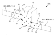
- FIG. 1 shows the storage state and the deployed state of the deployable radiator 100.
- the deployable radiator 100 is mounted on the south or north face 10 of the satellite assembly.
- the unfolded radiator 100 includes a first radiator panel 20, a first unfolding mechanism 30, a second radiator panel 40, a second unfolding mechanism 50, and a holding and releasing mechanism 60.
- the illustration of the flexible tube connecting the steam pipe in the satellite structure and the condensing pipe in the radiator panel is omitted.
- the first radiator panel 20 is deployably coupled to the south or north face 10 of the satellite assembly by the first deployment mechanism 30.
- a first deployment mechanism 30 couples the first radiator panel 20 to the south or north face 10 of the satellite assembly. Further, the first deployment mechanism 30 deploys the first radiator panel 20 from the state where the first radiator panel 20 faces the south surface or the north surface 10 of the satellite assembly.
- the state of the first radiator panel 20 shown in the stored state of FIG. 1 is a state in which the first radiator panel 20 faces the south surface or the north surface 10 of the satellite assembly.
- the second radiator panel 40 is deployably coupled to the south or north face 10 of the satellite assembly by the second deployment mechanism 50.
- the second radiator panel 40 overlaps the first radiator panel 20 and faces the south or north surface 10 of the satellite assembly in a state where the first radiator panel 20 is opposed to the south or north surface 10 of the satellite assembly. It is sandwiched between the south or north face 10 of the satellite assembly and the first radiator panel 20. That is, the second radiator panel 40 is sandwiched between the south surface or the north surface 10 of the satellite assembly and the first radiator panel 20 in the storage state of FIG. 1 and overlaps the first radiator panel 20. ing.
- a second deployment mechanism 50 couples the second radiator panel 40 to the south or north face 10 of the satellite assembly.
- the second deployment mechanism 50 sets the second radiator panel 40 in a direction P2 opposite to the deployment direction P1 of the first radiator panel from the state where the second radiator panel 40 faces the south or north face 10 of the satellite assembly.
- the holding and releasing mechanism 60 comprises, for example, a bolt for fixing the panel, a separation nut for engaging with the bolt, and a bracket for mounting them.
- a separation nut is a device in which an internal nut is broken by an electrical signal and disengages from a bolt.
- the holding and releasing mechanism 60 is configured such that the first radiator panel 20 and the second radiator panel are in a state in which the first radiator panel 20 and the second radiator panel 40 overlap and face the south surface or the north surface 10 of the satellite assembly. 40 and hold. That is, the holding and releasing mechanism 60 overlaps and holds the first radiator panel 20 and the second radiator panel 40 in the storage state of FIG. 1.
- the holding and releasing mechanism 60 releases the first radiator panel and the second radiator panel from the state of holding the first radiator panel 20 and the second radiator panel 40.
- the storage state of FIG. 1 is a state in which the holding and releasing mechanism 60 holds the first radiator panel 20 and the second radiator panel 40 in an overlapping manner. Further, in the unfolded state of FIG. 1, the holding and releasing mechanism 60 is in a state in which the first radiator panel 20 and the second radiator panel 40 are released.
- the second radiator panel 40 is first accommodated so as to face the south or north surface 10 of the satellite assembly, and the first radiator panel 20 is overlapped from the outside of the accommodated second radiator panel 40. And store it so as to face the south or north face 10 of the satellite structure. Then, the holding and releasing mechanism 60 fixes the two overlapping radiator panels.
- a surface facing the south surface or the north surface 10 of the satellite assembly is referred to as a first facing surface 21, and a surface opposite to the first facing surface 21 is referred to as an outer surface 22.
- a surface facing the south surface or the north surface 10 of the satellite assembly is referred to as a second facing surface 41, and a surface opposite to the second facing surface 41 is referred to as a second outer surface 42.
- the outer layer surface 22 of the first radiator panel 20 is the outermost layer surface exposed to the outer space in the stored state.
- the first deployment mechanism 30 and the second deployment mechanism 50 are, for example, hinges consisting of a bearing, a shaft and a bracket.
- the first deployment mechanism 30 and the second deployment mechanism 50 are driven by a drive source to obtain a panel deployment force.
- the first deployment mechanism 30 and the second deployment mechanism 50 are driven by elastic energy of a spring.
- the first deployment mechanism 30 and the second deployment mechanism 50 may be driven by a motor.
- the first deployment mechanism 30 and the second deployment mechanism 50 may be driven by combining the elastic energy of a spring and a motor.
- FIG. 2 shows a spread type radiator 100x of a comparative example for comparison with the spread type radiator 100 according to the present embodiment.
- the holding and releasing mechanisms 60 are required for the number of panels. For example, in the case where eight holding / releasing mechanisms 60 are required per radiator panel, 16 points are required for two radiator panels.
- the manufacturing cost also increases.
- the expansion type radiator 100x of the comparative example since the radiator panels are independently fixed to the south surface or the north surface 10 of the satellite assembly, the area occupied by the radiator panels in the stored state is also doubled. As described above, since the occupied area of the south surface or the north surface 10 of the satellite assembly by the stored radiator panel is large, the degree of freedom in the arrangement of the satellites becomes narrow. For example, equipment layout problems such as the stored radiator panel interfering with the solar cell paddle may occur.
- the radiator panels are stacked and held in the storage state. Therefore, the radiator panels can be stacked and fixed to the south or north face 10 of the satellite assembly by the same holding and releasing mechanism 60, and the holding and releasing mechanism 60 may be one panel.
- the holding and releasing mechanism 60 may be one panel.
- eight holding / releasing mechanisms 60 are required per radiator panel, even if there are two radiator panels, only eight points are required. Therefore, according to the unfolding type radiator 100 which concerns on this Embodiment, the increase in the mass of a satellite can be suppressed.
- the occupied area of the south surface or the north face 10 of the satellite assembly by the radiator panel in the stored state is smaller than that of the unfolded radiator 100x of the comparative example.
- the occupied area is 1/2 of the unfolded radiator 100x of the comparative example. Therefore, according to the unfolding type radiator 100 which concerns on this Embodiment, the freedom degree of apparatus arrangement
- the unfolding mechanism of the radiator panel can be driven by elastic energy of a spring. Therefore, according to the unfolding type radiator 100 which concerns on this Embodiment, an unfolding mechanism can be implement
- the unfolding mechanism of the radiator panel may be driven by a motor.
- the unfolding type radiator 100 according to the present embodiment by driving with the motor, the unfolding can be controlled so that the panels are not interfered by controlling the motor.
- it since it is possible to generate a torque larger than that of a spring, it can cope with a large radiator panel.
- the radiator panel can be oriented on the orbit at any timing, for example, at the timing of abnormal posture, and then returned to the storage state to reduce power consumption for temperature control of the satellite. .
- Second Embodiment differences from the first embodiment will be mainly described.
- the same components as those described in the first embodiment may be denoted by the same reference numerals, and the description thereof may be omitted.
- the mold radiator 100a while minimizing the heat loss in the spacecraft during orbit raising, it is possible to further maximize the exhaust heat after reaching the geostationary orbit than in Embodiment 1, and minimize the mass of the satellite.
- the mold radiator 100a will be described.
- the outer layer surface 22 of the first radiator panel 20 is the outermost layer surface in the stored state. Therefore, in order to minimize heat loss in the spacecraft during orbit raising, it is necessary to thermally insulate the outer surface 22 of the first radiator panel 20 which is the outermost surface. That is, it is necessary to prevent heat from being dissipated from the outer layer surface 22 of the first radiator panel 20 which is the outermost layer surface.
- the outer surface 22 which is the opposite surface of the first facing surface 21 facing the south or north surface 10 of the satellite assembly, is thermally insulated.
- at least a part of the outer surface 22 is a heat insulating surface 71.
- the heat insulating surface 71 is specifically generated by attaching a heat insulating material to the outer surface 22. More specifically, the heat insulating surface 71 is generated by attaching a space heat insulating material (Multi layer Insulation) such as a polyimide film to the outer surface 22.
- the heat removal amount of the heat insulating surface 71 to which the space heat insulating material is attached is substantially zero.
- first opposing surface 21 of the first radiator panel 20, the second opposing surface 41 of the second radiator panel 40, and the second outer surface 42 of the second radiator panel 40 are exhaust heat to be exhausted. It is the surface 72.
- the second outer side surface 42 is also referred to as a second intermediate surface. The first opposing surface 21 of the first radiator panel 20 and the both surfaces of the second radiator panel 40 need to dissipate heat in the unfolded state.
- unfolded radiator 100a will be described in comparison with a case where all the surfaces of the radiator panel in the unfolded radiator of FIGS.
- unfolded radiators have the following features. (1) In the unfolded radiator, the heat release areas of the unfolded state and the unfolded state differ greatly. Therefore, the deployable radiator can ensure the exhaust heat at the maximum when reaching the geostationary orbit, and can suppress the exhaust heat as much as possible at the time of orbit raising to suppress the power required for maintaining the temperature of the satellite. (2) In order to maximize the exhaust heat from the unfolded radiator panel, usually both sides of the radiator panel are heat exhaust surfaces.
- the heat dissipation efficiency of the radiator panel is lower than that of the satellite assembly surface.
- the difference is that the exhaust heat of the satellite assembly surface is 200 W per square meter, and the exhaust heat of the radiator panel is about 140 W per square meter. That is, the exhaust heat quantity of the radiator panel is about 70% of the exhaust heat quantity of the satellite assembly surface.
- the heat dissipation efficiency of the radiator is higher as the length of the flexible tube is shorter, the length of the flexible tube to be used needs to be minimized. Therefore, it is not practical to connect radiator panels in a wind screen like a solar cell paddle. For this reason, in the unfolded radiator, one radiator panel is directly connected to the satellite.
- the case where all the surfaces of the radiator panel are the heat exhausting surfaces 72 will be described as a first example.
- the first example since the south surface or the north surface 10 of the satellite assembly is covered with the area of two radiator panels in the storage state, the heat dissipation amount in the storage state can be suppressed small. This is because, as described above, the heat removal efficiency of the radiator panel is smaller than the heat removal efficiency of the satellite assembly surface.
- An example is estimated below.
- the area (one side) of one radiator panel is 1 square meter
- the heat dissipation of the south or north side of the satellite assembly surface is 200 W per square meter
- the heat dissipation from the radiator panel is 140 W per square meter.
- 960/280 ⁇ 3.4 and the exhaust heat amount in the unfolded state is 3.4 times the exhaust heat amount in the stored state.
- the case where all the surfaces of the radiator panel are the heat exhausting surfaces 72 will be described as a second example.
- the heat dissipation amount in the stored state is larger than in the expanded radiator 100x of the comparative example shown in Become.
- An example is estimated below.
- the area of one radiator panel is 1 square meter
- the heat dissipation from the south or north side of the satellite assembly is 200 W per square meter
- the heat dissipation from the radiator panel is 140 W per square meter.
- 960/340 ⁇ 2.8 and the exhaust heat amount in the unfolded state is 2.8 times the exhaust heat amount in the stored state.
- 340/280 ⁇ 120%
- the power used to maintain the temperature of the satellite during orbit raising is increased by 20% over the first example.
- a space heat insulating material is attached to the outermost layer surface of the radiator panel opposite to the south surface or the north surface 10 of the satellite structure in the radiator panels overlapped in the storage state. Is almost zero.
- An example is estimated below.
- the area of one radiator panel is 1 square meter
- the heat dissipation from the south or north side of the satellite assembly is 200 W per square meter
- the heat dissipation from the radiator panel is 140 W per square meter.
- the absolute value of the exhaust heat amount in the developed state is smaller than 960 W in the case of the first example.
- the accommodated state of the first example The amount of exhaust heat is smaller than 280 W.
- the heat insulating area is provided on at least a part of the outer layer surface of the first radiator panel, which is the outermost layer surface in the stored state. And, in the unfolded radiator 100a, both the surfaces of the other first radiator panel and the second radiator panel are heat exhaust surfaces. Therefore, according to the spread type radiator 100a according to the present embodiment, since it is housed on the south surface or the north surface of the satellite assembly, it is possible to minimize the heat loss in the spacecraft during orbit raising, and discharge after reaching the geostationary orbit. The amount of heat can be maximized, and the satellite resources used such as the mass of satellites can be minimized.
- Embodiments 1 and 2 the difference from Embodiments 1 and 2 will be mainly described.
- the same components as those described in the first and second embodiments may be denoted by the same reference numerals, and the description thereof may be omitted.
- both sides of the first radiator panel 20 and both sides of the second radiator panel 40 are heat exhausting surfaces 72.
- the first radiator panel 20 is provided with a heat insulating panel 110 covering at least a part of the outer surface 22 in a state where the first radiator panel 20 faces the south surface or the north surface 10 of the satellite assembly.
- the heat insulation panel 110 is also referred to as a heat shielding panel, and is, for example, a solar cell panel in which a surface of a sandwich plate made of carbon fiber reinforced plastics (CFRP) and an aluminum honeycomb core is covered with a space heat insulating material.
- CFRP carbon fiber reinforced plastics
- the first radiator panel 20 includes the heat insulating panel 110 which is deployably coupled to the tip when deployed in the deployment direction P1.
- a surface facing the first radiator panel 20 in the stored state that is, a surface facing the south surface or the north surface 10 of the satellite assembly is referred to as a third facing surface 111.
- the surface which is the outermost layer surface in the stored state that is, the surface opposite to the third opposing surface 111 is taken as the third outer surface 112.
- the third outer side surface 112 is a heat insulation surface.
- the entire heat insulation panel 110 may be formed of a heat insulation material.
- the unfolded radiator 100 b includes a third unfolding mechanism 120 that unfoldably couples the heat insulating panel 110 to the first radiator panel 20.
- the third deployment mechanism 120 deploys the heat insulation panel 110 in the deployment direction P3 after deployment of the first radiator panel 20 in the deployment direction P1 by the first deployment mechanism 30 is started.
- the third deployment mechanism 120 may be driven by a spring or may be driven by a motor.
- the holding and releasing mechanism 60 overlaps and holds the first radiator panel 20, the second radiator panel 40, and the heat insulating panel 110 in the stored state.
- the rotation axis of the first deployment mechanism 30 and the rotation axis of the third deployment mechanism 120 are parallel in FIG. 4, the rotation axis of the third deployment mechanism 120 may be rotated 90 degrees. That is, the heat insulating panel 110 is unfoldably connected to the upper end or the lower end of the first radiator panel 20, and the heat insulating panel 110 is expanded from the first radiator panel 20 to the upper or lower side of FIG. It may be configured.
- Embodiments 1 to 3 the differences from Embodiments 1 to 3 will be mainly described.
- the same components as those described in the first to third embodiments may be assigned the same reference numerals and descriptions thereof may be omitted.
- the unfolded radiator 100c according to the present embodiment includes an unfolding delay mechanism 140 that starts unfolding of the second radiator panel 40 after unfolding of the first radiator panel 20 by 90 degrees or more.
- the deployment delay mechanism 140 includes a cam 142 provided at the base of the first radiator panel 20 and a roller 141 provided at the tip of the second radiator panel 40.
- FIG. 6 is a diagram showing the state transition of the deployment delay mechanism 140 according to the present embodiment.
- the configuration of the deployment delay mechanism 140 will be described using FIGS. 5 and 6.
- the deployment delay mechanism 140 has a cam 142 at the base of the first radiator panel 20 and a roller 141 at the tip of the second radiator panel 40.
- the first deployment mechanism 30 is located at a position where two upper and lower pairs are separated, and the roller 141 is located at the center, but the rotation center of the first deployment mechanism 30 and the rotation center of the roller 141 are the same. It is straight and agrees.
- FIG. 5 shows the stored state, the first expanded state, the second expanded state, and the expanded state.
- 6 shows the state of the roller 141 and the cam 142 in the stored state, the roller 141 and the cam 142 in the first expanded state, and the roller 141 and the cam 142 in the second expanded state.
- the first radiator panel 20 and the second radiator panel 40 are stored facing the south surface or the north surface 10 of the satellite assembly.
- the first unfolded state is a state where the first radiator panel 20 unfolds to 90 degrees or less. Since the roller 141 is restrained by the cam 142 from the stored state to the first expanded state, the second radiator panel 40 can not be expanded in the expanding direction P2. Specifically, the roller 141 is restrained by the cam 142 in a state where the spread angle of the first radiator panel 20 is 90 degrees or less. For example, the roller 141 may be restrained by the cam 142 up to 86 degrees, 87 degrees, or 89 degrees, and the restraint of the roller 141 by the cam 142 may be released at a further spread angle.
- the deployment angle is 90 degrees and the restraint of the roller 141 by the cam 142 is released.
- the first radiator panel 20 unfolds by 90 degrees so that the restraint by the cam 142 is released from the roller 141, and the second radiator panel 40 can be unfolded in the unfolding direction P2.
- the second deployed state the first radiator panel 20 is deployed 90 degrees or more, the second radiator panel 40 is deployed in the deployment direction P2, and the first radiator panel 20 completes deployment.
- both the first radiator panel 20 and the second radiator panel 40 have been unfolded. That is, it is in the full deployed state.
- the cam 142 restrains the roller 141 during the operation of the deployment delay mechanism 140 from the storage state to the first deployment state where the first radiator panel deploys to about 90 degrees, the second radiator panel 40 is stored. Maintain the condition. When the deployment of the first radiator panel 20 exceeds about 90 degrees, the cam 142 is unrestrained and the roller 141 becomes free, so the second radiator panel 40 starts deployment. This deployment delay prevents the two radiator panels from interfering with each other during deployment.
- the roller instead of the cam, the roller may be restrained by an electromagnetic actuator and released by an electrical signal. Any other scheme may be adopted as long as the function of the deployment delay mechanism described above can be realized.
- the unfolded radiator 100c according to the present embodiment is equipped with an unfolding delay mechanism for the second radiator panel to start unfolding after the first radiator panel unfolds by about 90 degrees or more. Therefore, according to the unfolding type radiator 100c according to the present embodiment, the two radiator panels do not collide with each other in the middle of the unfolding, so the unfolding can be performed without damaging the radiator panel. Further, according to the spread type radiator 100c in accordance with the present embodiment, spread reliability can be improved by preventing spread failure due to interference or sticking between the radiator panels.
- Embodiment 5 In the present embodiment, differences from Embodiments 1 to 4 will be mainly described. In the present embodiment, the same components as those described in the first to fourth embodiments may be assigned the same reference numerals and descriptions thereof may be omitted. In this embodiment, a variation of the unfolded radiator 100x described in FIG. 2 of the first embodiment will be described.
- a spread type radiator 100d according to the present embodiment will be described with reference to FIG.
- the unfolded radiator 100d is independently held by the south surface or the north surface 10 of the satellite assembly one by one so that the two radiator panels do not overlap in the storage state.
- the outer layer surface 22 of the first radiator panel 20 is the outermost layer surface
- the second outer surface 42 of the second radiator panel 40 is also the outermost layer surface.
- each of the outer layer surface 22 and the second outer surface 42 is a heat insulating surface 71.
- the heat insulating surface 71 is specifically generated by attaching a heat insulating material to each of the outer surface 22 and the second outer surface 42. More specifically, the heat insulating surface 71 is generated by attaching a space heat insulating material to each of the outer surface 22 and the second outer surface 42. The heat removal amount of the heat insulating surface 71 to which the space heat insulating material is attached is substantially zero.
- each of the outer layer surface 22 and the second outer surface 42 which is the outermost layer surface in the stored state, is used as the heat insulating region. Therefore, according to the deployment type radiator 100d according to the present embodiment, it is possible to suppress the heat loss in the space device during orbit raising.
- each of the outer layer surface 22 and the second outer surface 42 has a heat insulating panel 110 unfoldably connected to the tip of each of the first radiator panel 20 and the second radiator panel 40.
- the heat insulation panel 110 is similar to the heat insulation panel 110 described in the third embodiment.
- each of the outer layer surface 22 and the second outer surface 42 is thermally insulated by the heat insulating panel 110 in the stored state.
- each of the first radiator panel 20 and the second radiator panel 40 and each heat insulating panel 110 are coupled by the third unfolding mechanism 120 described in the third embodiment.
- both sides of the first radiator panel 20 and both sides of the second radiator panel 40 are heat exhausting surfaces 72.
- each of the outer layer surface 22 and the second outer surface 42 which is the outermost layer surface in the stored state, is thermally insulated by a heat insulating panel.
- both sides of the first radiator panel 20 and both sides of the second radiator panel 40 are heat exhausting surfaces 72. Therefore, according to the unfolding type radiator 100e according to the present embodiment, it is possible to suppress the heat loss in the space device during orbit raising and to further increase the exhaust heat amount after reaching the geostationary orbit.
Landscapes
- Engineering & Computer Science (AREA)
- Aviation & Aerospace Engineering (AREA)
- Remote Sensing (AREA)
- Life Sciences & Earth Sciences (AREA)
- Environmental & Geological Engineering (AREA)
- General Health & Medical Sciences (AREA)
- Toxicology (AREA)
- Environmental Sciences (AREA)
- Health & Medical Sciences (AREA)
- Biodiversity & Conservation Biology (AREA)
- Sustainable Development (AREA)
- Mechanical Engineering (AREA)
- Details Of Aerials (AREA)
- Aerials With Secondary Devices (AREA)
Abstract
第1の展開機構(30)は、第1のラジエーターパネル(20)が衛星構体の南面または北面(10)に対向した状態から、第1のラジエーターパネル(20)を展開する。第2のラジエーターパネル(40)は、第1のラジエーターパネル(20)が衛星構体の南面または北面(10)に対向した状態において、第1のラジエーターパネル(20)と重なって衛星構体の南面または北面(10)に対向しているとともに衛星構体の南面または北面(10)と第1のラジエーターパネル(20)との間に挟まれている。第2の展開機構(50)は、第2のラジエーターパネル(40)を衛星構体の南面または北面(10)に結合し、第2のラジエーターパネル(40)が衛星構体の南面または北面(10)に対向した状態から、第2のラジエーターパネル(40)を第1のラジエーターパネル(20)の展開方向P1と反対方向P2に展開する。
Description
本発明は、衛星に搭載される展開型ラジエーターに関する。
近年、人工衛星の大電力化に伴い、衛星からの排熱量は増加の一途である。従来の衛星構体面からのみの排熱では排熱面積が不足し、必要な排熱量が確保できなくなりつつある。この必要な排熱面積を確保する目的で、展開型ラジエーターが適用されている。
展開型ラジエーターは、打上げ時にはラジエーターパネルを衛星構体面に保持解放機構により固定している。保持解放機構は、衛星が軌道に到達すると、ラジエーターパネルを解放する。解放後、展開機構によりラジエーターパネルを展開して排熱面積を増大させる。ラジエーターパネル内には凝縮管が具備されており、衛星構体内には蒸気管が具備されている。これらの凝縮管と蒸気管とは熱輸送媒体が通過する可撓性チューブによって連結されている。衛星構体内で生じた熱量は蒸気管内の熱輸送媒体によって、可撓性チューブを経由してラジエーターパネル内の凝縮管に輸送され、ラジエーターパネルの排熱面から排熱される。なお、ラジエーターパネルの排熱面には、太陽光反射板(Optical Solar Reflector)が貼付されている。
特許文献1は、ループ型ヒートパイプの熱輸送能力を向上させた展開型ラジエーターに関する。また、複数枚のラジエーターパネルを衛星に搭載する構成が開示されている。
特許文献2は、オービットレイジング中、すなわちトランスファー軌道の間の宇宙器における熱損失を防止するためのシステムおよび装置に関する。オービットレイジング中に熱遮蔽パネルで排熱面を覆って排熱量を抑制し、静止軌道上で展開して排熱量を増大させる技術が開示されている。
特許文献3は、展開型ラジエーターを4枚搭載する衛星において、衛星の東西面にそれぞれ2枚のラジエーターパネルを重ねて収納する技術が開示されている。
特許文献2は、オービットレイジング中、すなわちトランスファー軌道の間の宇宙器における熱損失を防止するためのシステムおよび装置に関する。オービットレイジング中に熱遮蔽パネルで排熱面を覆って排熱量を抑制し、静止軌道上で展開して排熱量を増大させる技術が開示されている。
特許文献3は、展開型ラジエーターを4枚搭載する衛星において、衛星の東西面にそれぞれ2枚のラジエーターパネルを重ねて収納する技術が開示されている。
衛星の大型化による排熱量の増大にともない、ラジエーターパネルの必要面積も増大するが、製造性の観点からラジエーターパネルは複数枚に分割して製造される傾向にある。
特許文献1および特許文献2では、複数枚のラジエーターパネルが重ならないように1枚ずつ独立に衛星構体に保持されているので、保持解放機構がラジエーターパネルの枚数分だけ必要となる。よって、衛星の質量が増大するという課題がある。また、収納時の占有面積が大きいため、衛星の機器配置の自由度が狭くなるという課題がある。
特許文献3では、東西面にラジエーターパネルを重ねて保持しているため、ラジエーターパネル展開前でも、排熱面である衛星構体の南北面が宇宙空間に露出している。よって、排熱量が大きいため、オービットレイジング中の宇宙器の熱損失を防止できない。なお、衛星構体の南北面は、通常は排熱面として利用し、東西面は排熱面とはしない。
本発明は、衛星の質量の増加を抑制するとともに、衛星の機器配置の自由度を向上させることができる展開型ラジエーターを提供することを目的とする。また、オービットレイジング中の宇宙器における熱損失を抑えるとともに静止軌道到達後の排熱量をより向上させることを目的とする。
本発明に係る展開型ラジエーターは、衛星構体に搭載された展開型ラジエーターにおいて、
第1のラジエーターパネルと、
前記第1のラジエーターパネルを前記衛星構体に結合する第1の展開機構であって、前記第1のラジエーターパネルが前記衛星構体の南面または北面に対向した状態から、前記第1のラジエーターパネルを展開する第1の展開機構と、
前記第1のラジエーターパネルが前記衛星構体の南面または北面に対向した状態において、前記第1のラジエーターパネルと重なって前記衛星構体の南面または北面に対向しているとともに前記衛星構体の南面または北面と前記第1のラジエーターパネルとの間に挟まれた第2のラジエーターパネルと、
前記第2のラジエーターパネルを前記衛星構体に結合する第2の展開機構であって、前記第2のラジエーターパネルが前記衛星構体の南面または北面に対向した状態から、前記第2のラジエーターパネルを前記第1のラジエーターパネルの展開方向と反対方向に展開する第2の展開機構とを備えた。
本発明に係る展開型ラジエーターでは、第1のラジエーターパネルは、第1の展開機構により衛星構体に結合される。第1の展開機構は、第1のラジエーターパネルが衛星構体の南面または北面に対向した状態から、第1のラジエーターパネルを展開する。また、第2のラジエーターパネルは、第1のラジエーターパネルが衛星構体の南面または北面に対向した状態において、第1のラジエーターパネルと重なって衛星構体の南面または北面に対向しているとともに衛星構体と第1のラジエーターパネルとの間に挟まれている。第2の展開機構は、第2のラジエーターパネルを衛星構体に結合し、第2のラジエーターパネルが衛星構体の南面または北面に対向した状態から、第2のラジエーターパネルを第1のラジエーターパネルの展開方向と反対方向に展開する。よって、本発明に係る展開型ラジエーターによれば、衛星構体の南面または北面におけるラジエーターパネルの保持面積を小さくできるので、衛星の質量の増加を抑制するとともに、衛星の機器配置の自由度を向上させることができる。また、展開型ラジエーターは、衛星構体の南面または北面に収納されているため、オービットレイジング中の宇宙器における熱損失を抑えるとともに静止軌道到達後の排熱量をより向上させることが可能となる。
以下、本発明の実施の形態について、図を用いて説明する。なお、各図中、同一または相当する部分には、同一符号を付している。実施の形態の説明において、同一または相当する部分については、説明を適宜省略または簡略化する。
実施の形態1.
***構成の説明***
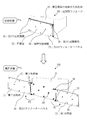
図1を用いて、本実施の形態に係る展開型ラジエーター100の構成について説明する。図1では、展開型ラジエーター100の収納状態と展開状態とを示している。
展開型ラジエーター100は、衛星構体の南面または北面10に搭載される。
展開型ラジエーター100は、第1のラジエーターパネル20と、第1の展開機構30と、第2のラジエーターパネル40と、第2の展開機構50と、保持解放機構60とを備える。
なお、以下において、衛星構体内の蒸気管とラジエーターパネル内の凝縮管とを結ぶ可撓性チューブの図示は省略する。
***構成の説明***
図1を用いて、本実施の形態に係る展開型ラジエーター100の構成について説明する。図1では、展開型ラジエーター100の収納状態と展開状態とを示している。
展開型ラジエーター100は、衛星構体の南面または北面10に搭載される。
展開型ラジエーター100は、第1のラジエーターパネル20と、第1の展開機構30と、第2のラジエーターパネル40と、第2の展開機構50と、保持解放機構60とを備える。
なお、以下において、衛星構体内の蒸気管とラジエーターパネル内の凝縮管とを結ぶ可撓性チューブの図示は省略する。
第1のラジエーターパネル20は、第1の展開機構30により衛星構体の南面または北面10に展開可能に結合される。
第1の展開機構30は、第1のラジエーターパネル20を衛星構体の南面または北面10に結合する。また、第1の展開機構30は、第1のラジエーターパネル20が衛星構体の南面または北面10に対向した状態から、第1のラジエーターパネル20を展開する。図1の収納状態に示す第1のラジエーターパネル20の状態が、第1のラジエーターパネル20が衛星構体の南面または北面10に対向した状態である。
第1の展開機構30は、第1のラジエーターパネル20を衛星構体の南面または北面10に結合する。また、第1の展開機構30は、第1のラジエーターパネル20が衛星構体の南面または北面10に対向した状態から、第1のラジエーターパネル20を展開する。図1の収納状態に示す第1のラジエーターパネル20の状態が、第1のラジエーターパネル20が衛星構体の南面または北面10に対向した状態である。
第2のラジエーターパネル40は、第2の展開機構50により衛星構体の南面または北面10に展開可能に結合される。第2のラジエーターパネル40は、第1のラジエーターパネル20が衛星構体の南面または北面10に対向した状態において、第1のラジエーターパネル20と重なって衛星構体の南面または北面10に対向しているとともに衛星構体の南面または北面10と第1のラジエーターパネル20との間に挟まれている。すなわち、第2のラジエーターパネル40は、図1の収納状態において、衛星構体の南面または北面10と第1のラジエーターパネル20との間に挟まれており、かつ、第1のラジエーターパネル20と重なっている。
第2の展開機構50は、第2のラジエーターパネル40を衛星構体の南面または北面10に結合する。また、第2の展開機構50は、第2のラジエーターパネル40が衛星構体の南面または北面10に対向した状態から、第2のラジエーターパネル40を第1のラジエーターパネルの展開方向P1と反対方向P2に展開する。
保持解放機構60は、例えば、パネルを固定するボルト、ボルトと係合するセパレーションナット、それらを取り付けるブラケットから構成される。セパレーションナットとは、電気信号によって内部のナットが分裂し、ボルトとの係合を解除するデバイスである。保持解放機構60は、第1のラジエーターパネル20と第2のラジエーターパネル40とが重なって衛星構体の南面または北面10に対向している状態において、第1のラジエーターパネル20と第2のラジエーターパネル40とを重ねて保持する。すなわち、保持解放機構60は、図1の収納状態において、第1のラジエーターパネル20と第2のラジエーターパネル40とを重ねて保持する。また、保持解放機構60は、第1のラジエーターパネル20と第2のラジエーターパネル40とを保持した状態から、前記第1のラジエーターパネルと前記第2のラジエーターパネルとを解放する。
図1の収納状態が、保持解放機構60が、第1のラジエーターパネル20と第2のラジエーターパネル40とを重ねて保持した状態である。また、図1の展開状態が、保持解放機構60が、第1のラジエーターパネル20と第2のラジエーターパネル40とを解放した状態である。
図1の収納状態が、保持解放機構60が、第1のラジエーターパネル20と第2のラジエーターパネル40とを重ねて保持した状態である。また、図1の展開状態が、保持解放機構60が、第1のラジエーターパネル20と第2のラジエーターパネル40とを解放した状態である。
展開型ラジエーター100では、第2のラジエーターパネル40を先に衛星構体の南面または北面10と対向するように収納し、収納された第2のラジエーターパネル40の外側から第1のラジエーターパネル20を重ねて衛星構体の南面または北面10と対向するように収納する。そして、保持解放機構60が重なった2枚のラジエーターパネルを固定する。
第1のラジエーターパネル20において、衛星構体の南面または北面10と対向する面を第1対向面21とし、第1対向面21の反対面を外層面22とする。また、第2のラジエーターパネル40において、衛星構体の南面または北面10と対向する面を第2対向面41とし、第2対向面41の反対面を第2外側面42とする。図1に示すように、第1のラジエーターパネル20の外層面22は、収納状態において、宇宙空間に露出する最外層面となる。
第1のラジエーターパネル20において、衛星構体の南面または北面10と対向する面を第1対向面21とし、第1対向面21の反対面を外層面22とする。また、第2のラジエーターパネル40において、衛星構体の南面または北面10と対向する面を第2対向面41とし、第2対向面41の反対面を第2外側面42とする。図1に示すように、第1のラジエーターパネル20の外層面22は、収納状態において、宇宙空間に露出する最外層面となる。
第1の展開機構30および第2の展開機構50は、例えば、軸受、シャフトおよびブラケットから成るヒンジである。第1の展開機構30および第2の展開機構50は、駆動源により駆動されパネル展開力を得る。
第1の展開機構30と第2の展開機構50とは、ばねの弾性エネルギーにより駆動されている。あるいは、第1の展開機構30と第2の展開機構50とは、モータにより駆動されていてもよい。あるいは、第1の展開機構30と第2の展開機構50とは、ばねの弾性エネルギーとモータとを組み合わせて駆動されていてもよい。
第1の展開機構30と第2の展開機構50とは、ばねの弾性エネルギーにより駆動されている。あるいは、第1の展開機構30と第2の展開機構50とは、モータにより駆動されていてもよい。あるいは、第1の展開機構30と第2の展開機構50とは、ばねの弾性エネルギーとモータとを組み合わせて駆動されていてもよい。
***本実施の形態の効果の説明***
図2は、本実施の形態に係る展開型ラジエーター100と比較するための比較例の展開型ラジエーター100xである。
図2に示すように、比較例の展開型ラジエーター100xでは、収納状態において、2枚のラジエーターパネルが重ならないように1枚ずつ独立に衛星構体の南面または北面10に保持されている。
このように、比較例の展開型ラジエーター100xでは、ラジエーターパネルをそれぞれ独立に衛星構体の南面または北面10に固定するため、保持解放機構60がパネル枚数分だけ必要となる。例えば、保持解放機構60がラジエーターパネル1枚当たり8点必要である場合、ラジエーターパネル2枚であれば16点必要となる。よって、衛星の質量が増加するとともに製造コストも増加する。
また、比較例の展開型ラジエーター100xでは、ラジエーターパネルをそれぞれ独立に衛星構体の南面または北面10に固定するため、収納状態でラジエーターパネルが占有する面積も2倍となる。このように、収納状態のラジエーターパネルによる衛星構体の南面または北面10の占有面積が大きいため、衛星の機器配置の自由度が狭くなる。例えば、収納状態のラジエーターパネルが太陽電池パドルと干渉するといった機器配置の不具合が生じる可能性がある。
一方、本実施の形態に係る展開型ラジエーター100では、収納状態において、2枚のラジエーターパネルを重ねて保持する。よって、ラジエーターパネルを重ねて同じ保持解放機構60で衛星構体の南面または北面10に固定することができ、保持解放機構60がパネル1枚分でよい。例えば、保持解放機構60がラジエーターパネル1枚当たり8点必要である場合、ラジエーターパネル2枚であっても8点あればよい。よって、本実施の形態に係る展開型ラジエーター100によれば、衛星の質量の増加を抑制することができる。
また、本実施の形態に係る展開型ラジエーター100によれば、収納状態のラジエーターパネルによる衛星構体の南面または北面10の占有面積が比較例の展開型ラジエーター100xと比較して小さい。具体的には、図1の展開型ラジエーター100では、比較例の展開型ラジエーター100xの1/2の占有面積である。よって、本実施の形態に係る展開型ラジエーター100によれば、衛星の機器配置の自由度が広くなる。例えば、収納状態のラジエーターパネルと太陽電池パドルとを並べて設置できるというように、衛星の機器配置の自由度が広くなる。
また、本実施の形態に係る展開型ラジエーター100によれば、収納状態のラジエーターパネルによる衛星構体の南面または北面10の占有面積が比較例の展開型ラジエーター100xと比較して小さい。具体的には、図1の展開型ラジエーター100では、比較例の展開型ラジエーター100xの1/2の占有面積である。よって、本実施の形態に係る展開型ラジエーター100によれば、衛星の機器配置の自由度が広くなる。例えば、収納状態のラジエーターパネルと太陽電池パドルとを並べて設置できるというように、衛星の機器配置の自由度が広くなる。
また、本実施の形態に係る展開型ラジエーター100では、ラジエーターパネルの展開機構が、ばねの弾性エネルギーで駆動することができる。よって、本実施の形態に係る展開型ラジエーター100によれば、モータあるいはモータ駆動電源といった複雑な部品を使用しないで展開機構を実現することができる。
一方、本実施の形態に係る展開型ラジエーター100では、ラジエーターパネルの展開機構が、モータで駆動されてもよい。本実施の形態に係る展開型ラジエーター100によれば、モータで駆動することにより、モータを制御してパネル同士が干渉しないように、展開させることができる。また、ばねより大きなトルクを発生させることが可能ため、大型のラジエーターパネルに対応できる。また、衛星の運用に応じて、軌道上で任意のタイミングにおいて最適な角度にラジエーターパネルを指向させることができる。また、衛星の運用に応じて、軌道上でラジエーターパネルを任意のタイミング、例えば異常姿勢時といったタイミングで指向させ、その後収納状態に戻して衛星の温度制御のための消費電力を削減することができる。
実施の形態2.
本実施の形態では、主に、実施の形態1との差異について説明する。
本実施の形態において、実施の形態1で説明した構成と同様の構成については同一の符号を付し、その説明を省略する場合がある。
本実施の形態では、オービットレイジング中の宇宙器における熱損失を最小に抑えつつ、静止軌道到達後の排熱量を実施の形態1よりさらに最大化でき、かつ、衛星の質量を最小限にできる展開型ラジエーター100aについて説明する。
本実施の形態では、主に、実施の形態1との差異について説明する。
本実施の形態において、実施の形態1で説明した構成と同様の構成については同一の符号を付し、その説明を省略する場合がある。
本実施の形態では、オービットレイジング中の宇宙器における熱損失を最小に抑えつつ、静止軌道到達後の排熱量を実施の形態1よりさらに最大化でき、かつ、衛星の質量を最小限にできる展開型ラジエーター100aについて説明する。
***構成の説明***
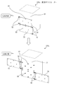
図3を用いて、本実施の形態に係る展開型ラジエーター100aの構成について説明する。
図3に示すように、第1のラジエーターパネル20の外層面22は、収納状態において、最外層面となる。よって、オービットレイジング中の宇宙器における熱損失を最小に抑えるためには、最外層面となる第1のラジエーターパネル20の外層面22を断熱する必要がある。つまり、最外層面となる第1のラジエーターパネル20の外層面22から熱を逃がさないようにする必要がある。
図3を用いて、本実施の形態に係る展開型ラジエーター100aの構成について説明する。
図3に示すように、第1のラジエーターパネル20の外層面22は、収納状態において、最外層面となる。よって、オービットレイジング中の宇宙器における熱損失を最小に抑えるためには、最外層面となる第1のラジエーターパネル20の外層面22を断熱する必要がある。つまり、最外層面となる第1のラジエーターパネル20の外層面22から熱を逃がさないようにする必要がある。
第1のラジエーターパネル20は、衛星構体の南面または北面10と対向する第1対向面21の反対面である外層面22の少なくとも一部が断熱されている。例えば、第1のラジエーターパネルは、外層面22の少なくとも一部を断熱面71とする。断熱面71は、具体的には、外層面22に断熱材を取り付けることにより生成される。より具体的には、断熱面71は、外層面22にポリイミドフィルムなどによる宇宙用断熱材(Multi layer Insulation)を取り付けることにより生成される。この宇宙用断熱材を取り付けた断熱面71の排熱量はほぼゼロとなる。
なお、第1のラジエーターパネル20の第1対向面21と、第2のラジエーターパネル40の第2対向面41と、第2のラジエーターパネル40の第2外側面42とは、排熱する排熱面72である。第2外側面42は、第2中間面ともいう。第1のラジエーターパネル20の第1対向面21と第2のラジエーターパネル40の両面とは、展開状態において排熱する必要がある。
なお、第1のラジエーターパネル20の第1対向面21と、第2のラジエーターパネル40の第2対向面41と、第2のラジエーターパネル40の第2外側面42とは、排熱する排熱面72である。第2外側面42は、第2中間面ともいう。第1のラジエーターパネル20の第1対向面21と第2のラジエーターパネル40の両面とは、展開状態において排熱する必要がある。
ここで、本実施の形態に係る展開型ラジエーター100aについて、図1および図2の展開型ラジエーターにおいてラジエーターパネルの全ての面が排熱面72である場合と比較しながら説明する。
一般的に展開型ラジエーターは下記の特徴を備える。
(1)展開型ラジエーターは、展開状態と収納状態との排熱面積が大きく異なる。このため、展開型ラジエーターは、静止軌道到達時には排熱量を最大限に確保しつつ、オービットレイジング時には排熱量をできるだけ抑制して衛星の温度維持のための必要電力を抑制することが可能となる。
(2)展開状態のラジエーターパネルからの排熱量を最大にするため、通常はラジエーターパネルの両面が排熱面である。
(3)ラジエーターパネルの温度は、衛星構体面の南面または北面の温度より低いため、排熱効率はラジエーターパネルの方が衛星構体面より低い。その差は、衛星構体面の排熱量が1平方メートル当たり200Wに対し、ラジエーターパネルの排熱量は1平方メートル当たり140W程度である。すなわち、ラジエーターパネルの排熱量は、衛星構体面の排熱量の約70%である。
(4)ラジエーターの排熱効率は、可撓性チューブの長さが短い程効率が高いため、使用する可撓性チューブの長さは最短にする必要がある。よって、太陽電池パドルのように、屏風状にラジエーターパネルを連結させることは実用的ではない。このため展開型ラジエーターは、ラジエーターパネル1枚が衛星と直接連結される形態となっている。
図2に示す比較例の展開型ラジエーター100xにおいて、ラジエーターパネルの全ての面が排熱面72である場合を第1の例として説明する。第1の例の場合、収納状態においてラジエーターパネル2枚分の面積で衛星構体の南面または北面10を覆うため、収納状態の排熱量を小さく抑えることができる。これは、上述したように、ラジエーターパネルの排熱効率が、衛星構体面の排熱効率より小さいためである。
以下に一例を試算する。ラジエーターパネル1枚の面積(片面)を1平方メートルとし、衛星構体面の南面または北面の排熱量を1平方メートル当たり200W、ラジエーターパネルからの排熱量を1平方メートル当たり140Wとする。
収納状態では、ラジエーターパネル2枚表分の面積2平方メートルから宇宙空間へ排熱するため、2×140=280Wの排熱量である。
展開状態では、衛星構体面2平方メートル、ラジエーターパネル2枚表裏で4平方メートルであるため、2×200+4×140=960Wの排熱量である。
ここで、960/280≒3.4となり、展開状態の排熱量は収納状態の排熱量の3.4倍である。展開状態における排熱量が一定の場合、展開状態の排熱量と収納状態の排熱量の比率が大きいほど、収納状態の排熱量が少なく、衛星はオービットレイジング時に衛星の温度維持に使用する電力を削減できる。
次に、図1に示す展開型ラジエーター100において、ラジエーターパネルの全ての面が排熱面72である場合を第2の例として説明する。第2の例の場合、収納状態ではラジエーターパネル1枚分の面積で衛星構体の南面または北面10を覆うため、図2に示す比較例の展開型ラジエーター100xより、収納状態時の排熱量が大きくなる。
以下に一例を試算する。ラジエーターパネル1枚の面積を1平方メートルとし、衛星構体面の南面または北面の排熱量を1平方メートル当たり200W、ラジエーターパネルからの排熱量を1平方メートル当たり140Wとする。
収納状態では、衛星構体面1平方メートル、ラジエーターパネル1枚表分の面積1平方メートルから宇宙空間へ排熱するため、1×200+1×140=340Wの排熱量である。
展開状態では、衛星構体面2平方メートル、ラジエーターパネル2枚の各々の表裏で4平方メートルであるため、2×200+4×140=960Wの排熱量である。
ここで、960/340≒2.8となり、展開状態の排熱量は収納状態の排熱量の2.8倍である。340/280≒120%となり、第2の例では、オービットレイジング時に衛星の温度維持に使用する電力が第1の例より20%増大してしまう。
次に、図3に示す展開型ラジエーター100aについて説明する。
本実施の形態に係る展開型ラジエーター100aでは、収納状態時に重ね合せたラジエーターパネルにおいて、衛星構体の南面または北面10と反対側のラジエーターパネルの最外層面に宇宙用断熱材を取り付けられ、排熱量がほぼゼロとなっている。
以下に一例を試算する。ラジエーターパネル1枚の面積を1平方メートルとし、衛星構体面の南面または北面の排熱量を1平方メートル当たり200W、ラジエーターパネルからの排熱量を1平方メートル当たり140Wとする。
収納状態では、ラジエーターパネルの最外層面は断熱されているので、衛星構体面1平方メートルのみから宇宙空間へ排熱するため、1×200=200Wの排熱量である。
展開状態では、衛星構体面2平方メートル、ラジエーターパネル2枚の各々の表裏の合計で4平方メートルのうち、1面は断熱面であるため、2×200+3×140=820Wの排熱量である。
ここで、820/200=4.1となり、展開状態の排熱量は収納状態の排熱量の4.1倍である。この比率は、第1の例の場合より大きい。
なお、展開状態の排熱量絶対量は、第1の例の場合の960Wより小さい。しかし、ラジエーターパネルのサイズを拡張して展開状態の排熱量を960Wに統一した場合、展開型ラジエーター100aでは収納状態の排熱量は960/4.1=234Wとなり、第1の例の収納状態の排熱量280Wより小さく抑えられている。
***本実施の形態に係る効果の説明***
本実施の形態に係る展開型ラジエーター100aでは、収納状態において最外層面となる、第1のラジエーターパネルの外層面の少なくとも一部に、断熱領域を有している。そして、展開型ラジエーター100aでは、その他の第1のラジエーターパネルの面および第2のラジエーターパネルの両面は排熱面である。よって、本実施の形態に係る展開型ラジエーター100aによれば、衛星構体の南面または北面に収納されているため、オービットレイジング中の宇宙器における熱損失を最小に抑えつつ、静止軌道到達後の排熱量が最大化でき、かつ、衛星の質量といった使用する衛星リソースを最小限にできる。
本実施の形態に係る展開型ラジエーター100aでは、収納状態において最外層面となる、第1のラジエーターパネルの外層面の少なくとも一部に、断熱領域を有している。そして、展開型ラジエーター100aでは、その他の第1のラジエーターパネルの面および第2のラジエーターパネルの両面は排熱面である。よって、本実施の形態に係る展開型ラジエーター100aによれば、衛星構体の南面または北面に収納されているため、オービットレイジング中の宇宙器における熱損失を最小に抑えつつ、静止軌道到達後の排熱量が最大化でき、かつ、衛星の質量といった使用する衛星リソースを最小限にできる。
実施の形態3.
本実施の形態では、主に、実施の形態1および2との差異について説明する。
本実施の形態において、実施の形態1および2で説明した構成と同様の構成については同一の符号を付し、その説明を省略する場合がある。
本実施の形態では、主に、実施の形態1および2との差異について説明する。
本実施の形態において、実施の形態1および2で説明した構成と同様の構成については同一の符号を付し、その説明を省略する場合がある。
***構成の説明***
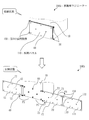
図4を用いて、本実施の形態に係る展開型ラジエーター100bの構成について説明する。
本実施の形態では、第1のラジエーターパネル20の両面と第2のラジエーターパネル40の両面とは、排熱面72であるものとする。
図4に示すように、第1のラジエーターパネル20は、第1のラジエーターパネル20が衛星構体の南面または北面10に対向した状態において、外層面22の少なくとも一部を覆う断熱パネル110を備えた。断熱パネル110は、熱遮蔽パネルともいい、例えば太陽電池パネルのように、CFRP(Carbon Fiber Reinforced Plastics)とアルミハニカムコアで構成されたサンドイッチ板の表面を宇宙用断熱材で覆ったものである。第1のラジエーターパネル20は、展開方向P1に展開した際の先端部に展開可能に結合された断熱パネル110を備える。
断熱パネル110において、収納状態において第1のラジエーターパネル20に対向する面、すなわち衛星構体の南面または北面10に対向する面を第3対向面111とする。また、断熱パネル110において、収納状態において最外層面となる面、すなわち第3対向面111の反対面を第3外側面112とする。断熱パネル110において、第3外側面112の少なくとも一部は断熱面であるものとする。あるいは、断熱パネル110全体が断熱素材で形成されていてもよい。
また、展開型ラジエーター100bは、断熱パネル110を第1のラジエーターパネル20に展開可能に結合する第3の展開機構120を備える。第3の展開機構120は、第1の展開機構30による第1のラジエーターパネル20の展開方向P1への展開が開始された後に、断熱パネル110を展開方向P3へ展開する。第3の展開機構120は、バネにより駆動されてもよいし、モータにより駆動されてもよい。
保持解放機構60は、収納状態において、第1のラジエーターパネル20と第2のラジエーターパネル40と断熱パネル110とを重ねて保持する。
なお、図4では、第1の展開機構30の回転軸と第3の展開機構120の回転軸が平行であるが、第3の展開機構120の回転軸を90度回転させてもよい。つまり、断熱パネル110を、第1のラジエーターパネル20の上端または下端に、展開可能に結合し、断熱パネル110が、第1のラジエーターパネル20から、図4の上側あるいは下側に展開するように構成してもよい。
なお、図4では、第1の展開機構30の回転軸と第3の展開機構120の回転軸が平行であるが、第3の展開機構120の回転軸を90度回転させてもよい。つまり、断熱パネル110を、第1のラジエーターパネル20の上端または下端に、展開可能に結合し、断熱パネル110が、第1のラジエーターパネル20から、図4の上側あるいは下側に展開するように構成してもよい。
***本実施の形態の効果の説明***
本実施の形態に係る展開型ラジエーター100bによれば、第1のラジエーターパネル20の両面と第2のラジエーターパネル40の両面とを排熱面とした場合でも、収納状態において最外層面を断熱することができる。よって、本実施の形態に係る展開型ラジエーター100bによれば、オービットレイジング中の宇宙器における熱損失を最小に抑えつつ、静止軌道到達後の排熱量をより大きくすることができる。
本実施の形態に係る展開型ラジエーター100bによれば、第1のラジエーターパネル20の両面と第2のラジエーターパネル40の両面とを排熱面とした場合でも、収納状態において最外層面を断熱することができる。よって、本実施の形態に係る展開型ラジエーター100bによれば、オービットレイジング中の宇宙器における熱損失を最小に抑えつつ、静止軌道到達後の排熱量をより大きくすることができる。
実施の形態4.
本実施の形態では、主に、実施の形態1から3との差異について説明する。
本実施の形態において、実施の形態1から3で説明した構成と同様の構成については同一の符号を付し、その説明を省略する場合がある。
本実施の形態では、主に、実施の形態1から3との差異について説明する。
本実施の形態において、実施の形態1から3で説明した構成と同様の構成については同一の符号を付し、その説明を省略する場合がある。
***構成の説明***
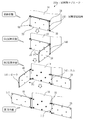
図5を用いて、本実施の形態に係る展開型ラジエーター100cの構成について説明する。
本実施の形態に係る展開型ラジエーター100cは、第1のラジエーターパネル20が90度以上展開してから第2のラジエーターパネル40の展開を開始させる展開遅延機構140を備えている。展開遅延機構140は、第1のラジエーターパネル20の根本に設けられたカム142と、第2のラジエーターパネル40の先端に設けられたローラ141とを備える。
図5を用いて、本実施の形態に係る展開型ラジエーター100cの構成について説明する。
本実施の形態に係る展開型ラジエーター100cは、第1のラジエーターパネル20が90度以上展開してから第2のラジエーターパネル40の展開を開始させる展開遅延機構140を備えている。展開遅延機構140は、第1のラジエーターパネル20の根本に設けられたカム142と、第2のラジエーターパネル40の先端に設けられたローラ141とを備える。
図6は、本実施の形態に係る展開遅延機構140の状態遷移を表した図である。
図5および図6を用いて、展開遅延機構140の構成について説明する。
図5に示すように、展開遅延機構140は、第1のラジエーターパネル20の根本にカム142を、第2のラジエーターパネル40の先端にローラ141を設ける。第1の展開機構30は、上下一対の2台が離れた位置にあり、ローラ141は、その中央に位置しているが、第1の展開機構30の回転中心とローラ141の回転中心は同一直線状にあり、一致している。
図5および図6を用いて、展開遅延機構140の構成について説明する。
図5に示すように、展開遅延機構140は、第1のラジエーターパネル20の根本にカム142を、第2のラジエーターパネル40の先端にローラ141を設ける。第1の展開機構30は、上下一対の2台が離れた位置にあり、ローラ141は、その中央に位置しているが、第1の展開機構30の回転中心とローラ141の回転中心は同一直線状にあり、一致している。
図5では、収納状態と第1展開状態と第2展開状態と展開状態とを示している。また、図6では、収納状態におけるローラ141とカム142、第1展開状態におけるローラ141とカム142、および第2展開状態におけるローラ141とカム142の状態を示している。
収納状態は、第1のラジエーターパネル20と第2のラジエーターパネル40とが衛星構体の南面または北面10に対向して、収納されている状態である。
第1の展開状態は、第1のラジエーターパネル20が90度以下まで展開した状態である。
収納状態から第1の展開状態までは、ローラ141がカム142に拘束されているので、第2のラジエーターパネル40は展開方向P2に展開することができない。具体的には、第1のラジエーターパネル20の展開角度が90度以下までの状態でローラ141がカム142に拘束される。例えば、86度、87度あるいは89度までローラ141がカム142に拘束され、それ以上の展開角度でカム142によるローラ141の拘束が解除されるとしてもよい。なお、以下の説明では、展開角度が90度でカム142によるローラ141の拘束が解除されるものとして説明する。
第1展開状態では、第1のラジエーターパネル20が90度展開してカム142による拘束がローラ141から外れ、第2のラジエーターパネル40が展開方向P2に展開可能となる。
第2展開状態では、第1のラジエーターパネル20が90度以上展開しており、第2のラジエーターパネル40が展開方向P2に展開し、第1のラジエーターパネル20が展開を完了する。
展開状態は、第1のラジエーターパネル20と第2のラジエーターパネル40がともに展開を完了した状態である。すなわち、全展開状態である。
展開遅延機構140の動作は、収納状態から第1のラジエーターパネルが約90度まで展開する第1展開状態までの間は、カム142がローラ141を拘束するため、第2のラジエーターパネル40は収納されている状態を維持する。第1のラジエーターパネル20の展開が約90度を越えると、カム142の拘束が外れ、ローラ141が自由になるため、第2のラジエーターパネル40が展開を開始する。この展開遅延により、2枚のラジエーターパネルが展開途中で干渉することが無くなる。
なお、他の方式としてローラを、カムの代わりに電磁アクチュエータで拘束し、電気信号によって解放してもよい。上述した展開遅延機構の機能を実現することができれば、他のどのような方式を採用しても構わない。
***本実施の形態の効果の説明***
本実施の形態に係る展開型ラジエーター100cは、第1のラジエーターパネルが約90度以上展開してから、第2のラジエーターパネルが展開を開始するための展開遅延機構を具備している。よって、本実施の形態に係る展開型ラジエーター100cによれば、2枚のラジエーターパネル同士が展開途中でぶつからないため、ラジエーターパネルを傷つけることなく展開することができる。また、本実施の形態に係る展開型ラジエーター100cによれば、ラジエーターパネル同士の干渉あるいは固着による展開不良を防ぐことで展開信頼性を向上させることができる。
本実施の形態に係る展開型ラジエーター100cは、第1のラジエーターパネルが約90度以上展開してから、第2のラジエーターパネルが展開を開始するための展開遅延機構を具備している。よって、本実施の形態に係る展開型ラジエーター100cによれば、2枚のラジエーターパネル同士が展開途中でぶつからないため、ラジエーターパネルを傷つけることなく展開することができる。また、本実施の形態に係る展開型ラジエーター100cによれば、ラジエーターパネル同士の干渉あるいは固着による展開不良を防ぐことで展開信頼性を向上させることができる。
実施の形態5.
本実施の形態では、主に、実施の形態1から4との差異について説明する。
本実施の形態において、実施の形態1から4で説明した構成と同様の構成については同一の符号を付し、その説明を省略する場合がある。
本実施の形態では、実施の形態1の図2で説明した展開型ラジエーター100xのバリエーションについて説明する。
本実施の形態では、主に、実施の形態1から4との差異について説明する。
本実施の形態において、実施の形態1から4で説明した構成と同様の構成については同一の符号を付し、その説明を省略する場合がある。
本実施の形態では、実施の形態1の図2で説明した展開型ラジエーター100xのバリエーションについて説明する。
図7を用いて、本実施の形態に係る展開型ラジエーター100dについて説明する。
展開型ラジエーター100dは、図2で説明したように、収納状態において、2枚のラジエーターパネルが重ならないように1枚ずつ独立に衛星構体の南面または北面10に保持されている。よって、収納状態において、第1のラジエーターパネル20の外層面22が最外層面となるとともに、第2のラジエーターパネル40の第2外側面42も最外層面となる。
展開型ラジエーター100dは、図2で説明したように、収納状態において、2枚のラジエーターパネルが重ならないように1枚ずつ独立に衛星構体の南面または北面10に保持されている。よって、収納状態において、第1のラジエーターパネル20の外層面22が最外層面となるとともに、第2のラジエーターパネル40の第2外側面42も最外層面となる。
外層面22と第2外側面42との各々は、少なくとも一部が断熱面71となっている。断熱面71は、具体的には、外層面22と第2外側面42との各々に断熱材を取り付けることにより生成される。より具体的には、断熱面71は、外層面22と第2外側面42との各々に、宇宙用断熱材を取り付けることにより生成される。この宇宙用断熱材を取り付けた断熱面71の排熱量はほぼゼロとなる。
図7の展開型ラジエーター100dでは、収納状態において最外層面となる、外層面22と第2外側面42との各々の少なくとも一部を断熱領域としている。よって、本実施の形態に係る展開型ラジエーター100dによれば、オービットレイジング中の宇宙器における熱損失を抑えることができる。
図8を用いて、本実施の形態に係る展開型ラジエーター100eについて説明する。
図8に示すように、外層面22と第2外側面42との各々は、第1のラジエーターパネル20と第2のラジエーターパネル40との各々の先端に展開可能に結合された断熱パネル110を備える。この断熱パネル110は、実施の形態3で説明した断熱パネル110と同様である。
展開型ラジエーター100eでは、外層面22と第2外側面42との各々は、収納状態において断熱パネル110により断熱される。このとき、第1のラジエーターパネル20と第2のラジエーターパネル40との各々と各断熱パネル110とは、実施の形態3で説明した第3の展開機構120により結合される。
展開型ラジエーター100eでは、第1のラジエーターパネル20の両面と第2のラジエーターパネル40の両面とは、排熱面72であるものとする。
図8の展開型ラジエーター100eでは、収納状態において最外層面となる、外層面22と第2外側面42との各々の少なくとも一部を断熱パネルにより断熱している。また、第1のラジエーターパネル20の両面と第2のラジエーターパネル40の両面とは、排熱面72である。よって、本実施の形態に係る展開型ラジエーター100eによれば、オービットレイジング中の宇宙器における熱損失を抑えるとともに、静止軌道到達後の排熱量をより大きくすることができる。
実施の形態1から5について説明したが、これらの実施の形態のうち、複数の実施の形態を組み合わせて実施してもよい。また、これらの実施の形態のうち、複数の部分を組み合わせて実施してもよい。あるいは、これらの実施の形態のうち、1つの部分を実施しても構わない。その他、これらの実施の形態の内容を、全体として、あるいは部分的に、どのように組合せて実施しても構わない。すなわち、発明の範囲内において、各実施の形態の自由な組み合わせ、各実施の形態の任意の構成要素の変形、または各実施の形態の任意の構成要素の省略が可能である。
上述した実施の形態は、本質的に好ましい例示であり、本発明、その適用物あるいは用途の範囲を制限することを意図するものではなく、必要に応じて種々の変更が可能である。上述した実施の形態は、本手法の理解を助けるためのものであって、発明を限定するためのものではない。
上述した実施の形態は、本質的に好ましい例示であり、本発明、その適用物あるいは用途の範囲を制限することを意図するものではなく、必要に応じて種々の変更が可能である。上述した実施の形態は、本手法の理解を助けるためのものであって、発明を限定するためのものではない。
100,100a,100b,100c,100d,100e,100x 展開型ラジエーター、10 衛星構体の南面または北面、20 第1のラジエーターパネル、21 第1対向面、22 外層面、30 第1の展開機構、40 第2のラジエーターパネル、41 第2対向面、42 第2外側面、50 第2の展開機構、60 保持解放機構、71 断熱面、72 排熱面、110 断熱パネル、111 第3対向面、112 第3外側面、120 第3の展開機構、140 展開遅延機構、141 ローラ、142 カム。
Claims (9)
- 衛星構体に搭載された展開型ラジエーターにおいて、
第1のラジエーターパネルと、
前記第1のラジエーターパネルを前記衛星構体に結合する第1の展開機構であって、前記第1のラジエーターパネルが前記衛星構体の南面または北面に対向した状態から、前記第1のラジエーターパネルを展開する第1の展開機構と、
前記第1のラジエーターパネルが前記衛星構体に対向した状態において、前記第1のラジエーターパネルと重なって前記衛星構体の南面または北面に対向しているとともに前記衛星構体と前記第1のラジエーターパネルとの間に挟まれた第2のラジエーターパネルと、
前記第2のラジエーターパネルを前記衛星構体に結合する第2の展開機構であって、前記第2のラジエーターパネルが前記衛星構体の南面または北面に対向した状態から、前記第2のラジエーターパネルを前記第1のラジエーターパネルの展開方向と反対方向に展開する第2の展開機構と
を備えた展開型ラジエーター。 - 前記展開型ラジエーターは、
前記第1のラジエーターパネルと前記第2のラジエーターパネルとが重なって前記衛星構体の南面または北面に対向している状態において、前記第1のラジエーターパネルと前記第2のラジエーターパネルとを重ねて保持するとともに、前記第1のラジエーターパネルと前記第2のラジエーターパネルとを保持した状態から、前記第1のラジエーターパネルと前記第2のラジエーターパネルとを解放する保持解放機構を備えた請求項1に記載の展開型ラジエーター。 - 前記第1のラジエーターパネルは、
前記衛星構体の南面または北面と対向する第1対向面の反対面である外層面の少なくとも一部が断熱されている請求項1または2に記載の展開型ラジエーター。 - 前記第1のラジエーターパネルは、
前記外層面の少なくとも一部に断熱材を取り付けた請求項3に記載の展開型ラジエーター。 - 前記第1のラジエーターパネルは、
前記第1のラジエーターパネルが前記衛星構体に対向した状態において、前記外層面の少なくとも一部を覆う断熱パネルを備えた請求項3に記載の展開型ラジエーター。 - 前記展開型ラジエーターは、
前記断熱パネルを前記第1のラジエーターパネルに展開可能に結合する第3の展開機構を備えた請求項5に記載の展開型ラジエーター。 - 前記展開型ラジエーターは、
前記第1のラジエーターパネルが90度以上展開してから前記第2のラジエーターパネルの展開を開始させる展開遅延機構を備えた請求項1から6のいずれか1項に記載の展開型ラジエーター。 - 前記第1の展開機構と前記第2の展開機構とは、バネの弾性エネルギーにより駆動されている請求項1から7のいずれか1項に記載の展開型ラジエーター。
- 前記第1の展開機構と前記第2の展開機構とは、モータにより駆動されている請求項1から8のいずれか1項に記載の展開型ラジエーター。
Priority Applications (3)
| Application Number | Priority Date | Filing Date | Title |
|---|---|---|---|
| EP17884097.1A EP3556666B1 (en) | 2016-12-19 | 2017-03-09 | Deployable radiator |
| JP2018557515A JP6698874B2 (ja) | 2016-12-19 | 2017-03-09 | 展開型ラジエーター |
| US16/347,266 US11492145B2 (en) | 2016-12-19 | 2017-03-09 | Deployable radiator |
Applications Claiming Priority (2)
| Application Number | Priority Date | Filing Date | Title |
|---|---|---|---|
| JP2016245932 | 2016-12-19 | ||
| JP2016-245932 | 2016-12-19 |
Publications (1)
| Publication Number | Publication Date |
|---|---|
| WO2018116490A1 true WO2018116490A1 (ja) | 2018-06-28 |
Family
ID=62626127
Family Applications (1)
| Application Number | Title | Priority Date | Filing Date |
|---|---|---|---|
| PCT/JP2017/009513 WO2018116490A1 (ja) | 2016-12-19 | 2017-03-09 | 展開型ラジエーター |
Country Status (4)
| Country | Link |
|---|---|
| US (1) | US11492145B2 (ja) |
| EP (1) | EP3556666B1 (ja) |
| JP (1) | JP6698874B2 (ja) |
| WO (1) | WO2018116490A1 (ja) |
Cited By (1)
| Publication number | Priority date | Publication date | Assignee | Title |
|---|---|---|---|---|
| CN114852378A (zh) * | 2022-03-31 | 2022-08-05 | 北京空间飞行器总体设计部 | 基于单相流体回路的可展开式热辐射器 |
Families Citing this family (5)
| Publication number | Priority date | Publication date | Assignee | Title |
|---|---|---|---|---|
| WO2019204463A1 (en) * | 2018-04-17 | 2019-10-24 | Raytheon Company | Thermally-enhanced and deployable structures |
| US11760510B1 (en) * | 2020-03-09 | 2023-09-19 | Maxar Space Llc | Spacecraft design with semi-rigid solar array |
| CN113879568B (zh) * | 2021-09-06 | 2022-07-12 | 中国科学院微小卫星创新研究院 | 一种可插拔的卫星热控系统及方法 |
| US12017806B2 (en) * | 2022-01-21 | 2024-06-25 | Maxar Space Llc | Satellite with modular radiator panels |
| CN117644996B (zh) * | 2023-12-06 | 2024-08-16 | 中国科学院微小卫星创新研究院 | 一种光学卫星 |
Citations (8)
| Publication number | Priority date | Publication date | Assignee | Title |
|---|---|---|---|---|
| JPS6361700A (ja) * | 1986-09-03 | 1988-03-17 | 工業技術院長 | 展開型パネルの保持解放装置 |
| EP0780304A1 (en) * | 1995-12-22 | 1997-06-25 | HE HOLDINGS, INC. dba HUGHES ELECTRONICS | Dual function deployable radiator and radiator cover |
| JP2003276696A (ja) * | 2002-03-27 | 2003-10-02 | Mitsubishi Electric Corp | 衛星用ヒートパイプパネル |
| JP2003312600A (ja) | 2002-04-18 | 2003-11-06 | Mitsubishi Electric Corp | 展開型ラジエータ及びそれを備えた人工衛星本体 |
| JP2005178773A (ja) * | 2003-12-23 | 2005-07-07 | Alcatel | 構造体の一可動本体の運動に応じて構造体を展開配置するシーケンス装置 |
| JP2008265522A (ja) * | 2007-04-20 | 2008-11-06 | Japan Aerospace Exploration Agency | 熱制御装置 |
| US20130200221A1 (en) | 2012-02-07 | 2013-08-08 | Lockheed Martin Corporation | Deployable radiator having an increased view factor |
| JP2016521225A (ja) | 2013-04-09 | 2016-07-21 | ロッキード マーティン コーポレイションLockheed Martin Corporation | 宇宙機並びに熱制御システム及び熱制御パネル |
Family Cites Families (11)
| Publication number | Priority date | Publication date | Assignee | Title |
|---|---|---|---|---|
| US4832113A (en) * | 1988-03-11 | 1989-05-23 | The United States Of America As Represented By The United States Department Of Energy | Survivable pulse power space radiator |
| US5732765A (en) * | 1995-12-22 | 1998-03-31 | Hughes Electronics | Adjustable heat rejection system |
| US5794890A (en) * | 1995-12-22 | 1998-08-18 | Hughes Electronics Corporation | Shielded radiator |
| US6220548B1 (en) * | 1998-09-14 | 2001-04-24 | The United States Of America As Represented By The Secretary Of The Navy | Deployed equipment modules for satellite architecture improvement |
| FR2823182B1 (fr) * | 2001-04-05 | 2004-06-04 | Cit Alcatel | Radiateur deployable pour engin spatial |
| US7874520B2 (en) * | 2006-03-21 | 2011-01-25 | Lockheed Martin Corporation | Satellite with deployable, articulatable thermal radiators |
| US20080289801A1 (en) * | 2007-05-02 | 2008-11-27 | Batty J Clair | Modular Thermal Management System for Spacecraft |
| EP2489593A1 (en) * | 2011-02-21 | 2012-08-22 | European Space Agency | Earth observation satellite, satellite system, and launching system for launching satellites |
| US8714492B2 (en) * | 2012-02-07 | 2014-05-06 | Lockheed Martin Corporation | Non-interfering deployable radiator arrangement for geo spacecraft |
| EP2956364B1 (en) | 2013-02-12 | 2020-07-15 | Lockheed Martin Corporation | Deployable radiator having an increased view factor |
| NL2016677B1 (en) * | 2016-04-26 | 2017-11-07 | Airbus Defence And Space Netherlands B V | Solar Panel and Flexible Radiator for a Spacecraft. |
-
2017
- 2017-03-09 US US16/347,266 patent/US11492145B2/en active Active
- 2017-03-09 JP JP2018557515A patent/JP6698874B2/ja active Active
- 2017-03-09 WO PCT/JP2017/009513 patent/WO2018116490A1/ja active Application Filing
- 2017-03-09 EP EP17884097.1A patent/EP3556666B1/en active Active
Patent Citations (8)
| Publication number | Priority date | Publication date | Assignee | Title |
|---|---|---|---|---|
| JPS6361700A (ja) * | 1986-09-03 | 1988-03-17 | 工業技術院長 | 展開型パネルの保持解放装置 |
| EP0780304A1 (en) * | 1995-12-22 | 1997-06-25 | HE HOLDINGS, INC. dba HUGHES ELECTRONICS | Dual function deployable radiator and radiator cover |
| JP2003276696A (ja) * | 2002-03-27 | 2003-10-02 | Mitsubishi Electric Corp | 衛星用ヒートパイプパネル |
| JP2003312600A (ja) | 2002-04-18 | 2003-11-06 | Mitsubishi Electric Corp | 展開型ラジエータ及びそれを備えた人工衛星本体 |
| JP2005178773A (ja) * | 2003-12-23 | 2005-07-07 | Alcatel | 構造体の一可動本体の運動に応じて構造体を展開配置するシーケンス装置 |
| JP2008265522A (ja) * | 2007-04-20 | 2008-11-06 | Japan Aerospace Exploration Agency | 熱制御装置 |
| US20130200221A1 (en) | 2012-02-07 | 2013-08-08 | Lockheed Martin Corporation | Deployable radiator having an increased view factor |
| JP2016521225A (ja) | 2013-04-09 | 2016-07-21 | ロッキード マーティン コーポレイションLockheed Martin Corporation | 宇宙機並びに熱制御システム及び熱制御パネル |
Non-Patent Citations (1)
| Title |
|---|
| See also references of EP3556666A4 |
Cited By (2)
| Publication number | Priority date | Publication date | Assignee | Title |
|---|---|---|---|---|
| CN114852378A (zh) * | 2022-03-31 | 2022-08-05 | 北京空间飞行器总体设计部 | 基于单相流体回路的可展开式热辐射器 |
| CN114852378B (zh) * | 2022-03-31 | 2024-05-24 | 北京空间飞行器总体设计部 | 基于单相流体回路的可展开式热辐射器 |
Also Published As
| Publication number | Publication date |
|---|---|
| US11492145B2 (en) | 2022-11-08 |
| EP3556666A4 (en) | 2019-11-13 |
| EP3556666B1 (en) | 2023-03-08 |
| US20190329912A1 (en) | 2019-10-31 |
| EP3556666A1 (en) | 2019-10-23 |
| JPWO2018116490A1 (ja) | 2019-03-28 |
| JP6698874B2 (ja) | 2020-05-27 |
Similar Documents
| Publication | Publication Date | Title |
|---|---|---|
| WO2018116490A1 (ja) | 展開型ラジエーター | |
| JP4308478B2 (ja) | 展開可能な宇宙船用放熱器 | |
| US11254452B2 (en) | Flexible radiative fin for a spacecraft | |
| JP6024061B2 (ja) | 大型かつ堅牢な展開可能構造物およびそのような構造物の展開および係止方法 | |
| US8448902B2 (en) | Satellite having multiple aspect ratios | |
| US8960608B2 (en) | Deployable radiator having an increased view factor | |
| US9889951B1 (en) | Spacecraft east-west radiator assembly | |
| US10207824B2 (en) | Radiator deployable for a satellite stabilized on three axes | |
| WO2017169080A1 (ja) | ヒートパイプパネルを用いた放熱装置 | |
| US7762499B1 (en) | Independent East/West thermal management system | |
| US7028953B2 (en) | Two-sided deployable thermal radiator system and method | |
| US20210318074A1 (en) | Heat transfer assemblies with compliant heat pipes | |
| JP4317456B2 (ja) | 伸縮可能な放熱器を備える宇宙機 | |
| US6854510B2 (en) | Spacecraft radiator system and method using cross-coupled deployable thermal radiators | |
| US6883588B1 (en) | Spacecraft radiator system using a heat pump | |
| US11962272B2 (en) | Z-fold solar array with curved substrate panels | |
| US20230049753A1 (en) | Retractable z-fold flexible blanket solar array | |
| US10183764B1 (en) | High capacity spacecraft | |
| JP2003276699A (ja) | 人工衛星 | |
| Amidieu | Development of a deployable radiator using a LHP as heat transfer element | |
| JP2003312600A (ja) | 展開型ラジエータ及びそれを備えた人工衛星本体 | |
| Harwell et al. | Advanced thermal control techniques for emerging communication satellites | |
| JPH04201800A (ja) | 展開型衛星構体 |
Legal Events
| Date | Code | Title | Description |
|---|---|---|---|
| ENP | Entry into the national phase |
Ref document number: 2018557515 Country of ref document: JP Kind code of ref document: A |
|
| 121 | Ep: the epo has been informed by wipo that ep was designated in this application |
Ref document number: 17884097 Country of ref document: EP Kind code of ref document: A1 |
|
| NENP | Non-entry into the national phase |
Ref country code: DE |
|
| WWE | Wipo information: entry into national phase |
Ref document number: 2017884097 Country of ref document: EP |