WO2018116335A1 - ガス発生装置 - Google Patents
ガス発生装置 Download PDFInfo
- Publication number
- WO2018116335A1 WO2018116335A1 PCT/JP2016/087706 JP2016087706W WO2018116335A1 WO 2018116335 A1 WO2018116335 A1 WO 2018116335A1 JP 2016087706 W JP2016087706 W JP 2016087706W WO 2018116335 A1 WO2018116335 A1 WO 2018116335A1
- Authority
- WO
- WIPO (PCT)
- Prior art keywords
- gas
- gas generator
- unit
- generator
- output
- Prior art date
- Legal status (The legal status is an assumption and is not a legal conclusion. Google has not performed a legal analysis and makes no representation as to the accuracy of the status listed.)
- Ceased
Links
Images


Classifications
-
- H—ELECTRICITY
- H10—SEMICONDUCTOR DEVICES; ELECTRIC SOLID-STATE DEVICES NOT OTHERWISE PROVIDED FOR
- H10P—GENERIC PROCESSES OR APPARATUS FOR THE MANUFACTURE OR TREATMENT OF DEVICES COVERED BY CLASS H10
- H10P72/00—Handling or holding of wafers, substrates or devices during manufacture or treatment thereof
- H10P72/04—Apparatus for manufacture or treatment
- H10P72/0402—Apparatus for fluid treatment
-
- C—CHEMISTRY; METALLURGY
- C01—INORGANIC CHEMISTRY
- C01B—NON-METALLIC ELEMENTS; COMPOUNDS THEREOF; METALLOIDS OR COMPOUNDS THEREOF NOT COVERED BY SUBCLASS C01C
- C01B13/00—Oxygen; Ozone; Oxides or hydroxides in general
- C01B13/10—Preparation of ozone
- C01B13/11—Preparation of ozone by electric discharge
-
- C—CHEMISTRY; METALLURGY
- C01—INORGANIC CHEMISTRY
- C01B—NON-METALLIC ELEMENTS; COMPOUNDS THEREOF; METALLOIDS OR COMPOUNDS THEREOF NOT COVERED BY SUBCLASS C01C
- C01B2201/00—Preparation of ozone by electrical discharge
- C01B2201/30—Dielectrics used in the electrical dischargers
- C01B2201/32—Constructional details of the dielectrics
-
- C—CHEMISTRY; METALLURGY
- C01—INORGANIC CHEMISTRY
- C01B—NON-METALLIC ELEMENTS; COMPOUNDS THEREOF; METALLOIDS OR COMPOUNDS THEREOF NOT COVERED BY SUBCLASS C01C
- C01B2201/00—Preparation of ozone by electrical discharge
- C01B2201/60—Feed streams for electrical dischargers
- C01B2201/64—Oxygen
-
- C—CHEMISTRY; METALLURGY
- C01—INORGANIC CHEMISTRY
- C01B—NON-METALLIC ELEMENTS; COMPOUNDS THEREOF; METALLOIDS OR COMPOUNDS THEREOF NOT COVERED BY SUBCLASS C01C
- C01B2201/00—Preparation of ozone by electrical discharge
- C01B2201/90—Control of the process
-
- Y—GENERAL TAGGING OF NEW TECHNOLOGICAL DEVELOPMENTS; GENERAL TAGGING OF CROSS-SECTIONAL TECHNOLOGIES SPANNING OVER SEVERAL SECTIONS OF THE IPC; TECHNICAL SUBJECTS COVERED BY FORMER USPC CROSS-REFERENCE ART COLLECTIONS [XRACs] AND DIGESTS
- Y02—TECHNOLOGIES OR APPLICATIONS FOR MITIGATION OR ADAPTATION AGAINST CLIMATE CHANGE
- Y02E—REDUCTION OF GREENHOUSE GAS [GHG] EMISSIONS, RELATED TO ENERGY GENERATION, TRANSMISSION OR DISTRIBUTION
- Y02E60/00—Enabling technologies; Technologies with a potential or indirect contribution to GHG emissions mitigation
- Y02E60/30—Hydrogen technology
- Y02E60/50—Fuel cells
Definitions
- This invention relates to a gas generator equipped with a plurality of gas generator units.
- various gas generators such as gas generators with different gas concentrations and flow rates using discharge are used. Are used, and a plurality of gas generators are required in a plurality of semiconductor manufacturing processes.
- a plurality of gas generation mechanisms each including a gas generator, a gas generation power source, a flow rate controller (MFC), etc. are provided corresponding to the multi-gas treatment process, and each gas generation mechanism independently corresponds to the gas. It is generally considered to build a supply system.
- the gas supply system includes a gas generator, a power source for gas generation, a raw material gas piping system that supplies the gas generator via an MFC that controls the flow rate of the raw material gas, It is necessary to provide a plurality of gas concentration detectors, output gas piping systems having flow meters, and the like for the gas output from the gas.
- the first generation gas generator for multi-gas treatment processes is realized by mounting a plurality of unit groups consisting of a gas generator unit, a gas generation power supply unit, a gas control unit, and an electric control unit. It was.
- the gas control unit includes a raw material gas piping system that supplies the gas generator via an MFC that controls the raw material gas flow rate, a concentration detector for output gas that is gas generated from the gas generator in the gas generation unit, This unit integrates an output gas piping system with a flow meter.
- the electric control unit is a unit that controls the concentration and gas amount of the gas control unit and output gas.
- Such a first generation gas generator needs to be configured by providing a plurality of the above-described unit groups, and the apparatus configuration becomes large, so it is difficult to increase the number of unit groups.
- a set of ozone generation units is supplied to the gas generator via a gas generator, a power source for gas generation, an MFC that controls the flow rate of the raw material gas, and the like.
- the first generation gas generator described above includes a gas generator necessary for gas supply, a power supply unit for generating gas, a gas supply / output controller, and an electric controller for managing the entire apparatus. 1 unit gas generating mechanism.
- each unit is equipped with a plurality of gas generation mechanisms to output independent gas specifications. It is necessary to mount a plurality of units divided into two, and there is a problem that a space for a gas generating device including a plurality of gas generating mechanisms is increased.
- Patent Document 1 is a second generation gas generator (part 1).
- the ozone system disclosed in Patent Document 1 employs a configuration in which a gas generated from one gas generator is output, and a piping system that outputs the gas is distributed. For this reason, the generated gas flow rate and the generated gas concentration must be supplied to the multi-gas processing apparatus in a constant state, and the processing gas supply condition to each gas processing apparatus is shared by only one condition. There was a problem that it was impossible to variably control the gas flow rate and concentration independently for the corresponding gas processing apparatus.
- Patent Document 2 is a second generation gas generator (part 1).
- the ozone gas supply system is configured as described above, and has multiple stages of integrated ozone generation units, so that the generated gas flow rate and concentration are independently variably controlled. It is possible.
- each of the multiple ozone generation units has all the functions of peripheral devices necessary for ozone generation, it is necessary to provide peripheral devices for each unit, and the number of peripheral devices can be reduced to make the entire device compact.
- peripheral devices for each unit, and the number of peripheral devices can be reduced to make the entire device compact.
- there are limitations such as production costs, the weight of each ozone generation unit becomes heavy, and repair maintenance takes time.
- the gas generator according to the present invention is a gas generator including a plurality of gas generator units each having a gas generator for generating an output gas, and is shared among the plurality of gas generator units.
- a plurality of alternating current power supplies for supplying a plurality of alternating current voltages to the gas generator unit, a raw material gas shared by the plurality of gas generator units and supplied by the plurality of gas generator units, and the plurality of gases
- a gas control unit that controls output gas generated by the generator unit, the gas control unit being provided corresponding to the plurality of gas generator units, each of which is input to the corresponding gas generator unit
- a plurality of mass flow controllers for controlling a raw material gas flow rate, which is a flow rate of the raw material gas, and the plurality of gas generator units are provided corresponding to the gas generating units.
- a plurality of auto pressure controllers for controlling an internal pressure which is a pressure in the gas generator of the generator unit, and a gas generator of the gas generator unit provided corresponding to each of the plurality of gas generator units.
- a plurality of gas concentration meters wherein the gas generator further includes an AC power supply control unit that performs an AC power control operation on the multi-AC power supply unit, The AC power control operation includes an operation of controlling the power amount of the corresponding AC voltage based on at least the detected concentration detected by the corresponding gas concentration meter with respect to the plurality of AC voltages, and the plurality of gas generators
- the unit, the multiple AC power supply unit, the gas control unit, and the AC power supply control unit are integrally provided.
- each of the plurality of gas generator units is configured integrally with a single unit of multiple AC power supply unit, gas control unit, and AC power supply control unit. It is possible to mount a plurality of gas generator units while realizing compactization of the entire apparatus and realizing integration and arrangement of gas control units.
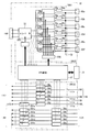
- FIG. 1 is an explanatory view schematically showing an internal configuration of a power source / gas control unit of a gas generator according to Embodiment 1 of the present invention.
- FIG. 2 is an explanatory view schematically showing the configuration of a plurality of gas generator units of the gas generator of Embodiment 1.
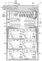
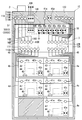
- FIG. 3 is an explanatory diagram showing an outline of an arrangement example of each component when the gas generator of Embodiment 1 is viewed from the front.
- FIG. 4 is an explanatory diagram illustrating an outline of an arrangement example of piping of each component viewed from the back surface of the gas generator according to the first embodiment.
- the overall configuration of the present invention includes a power generator / gas control unit 3 and a gas generator (ozone generator) 43 in the gas generator 1 of the first embodiment 6.
- a gas generator ozone generator
- the gas generator units (ozone gas generator units) 4a to 4f have the same configuration.
- the gas generator unit 4a will be described as a representative.
- the gas generator unit 4a has a gas generator (ozone generator) 43 and a transformer 44 as main components, inputs a raw material gas from a raw material supply port 41a connected by piping, and a gas output port 42a connected by piping.
- the ozone gas generated from is output as the output gas.
- the gas generator (ozone generator) 43 is cooled by the circulating cooling water pipe 46.
- the transformer 44 receives the high-frequency AC voltage output from the power supply / gas control unit 3 via the terminal 45 on the primary side of the transformer, and the high-frequency AC voltage is boosted to a high voltage on the secondary side of the transformer.
- the power factor of the power supply unit is increased by resonating with the inductance of the transformer 44 and the electrostatic capacity built in the gas generator 43, thereby obtaining a high voltage with high efficiency. Can do.
- gas generator unit 4 when the gas generator units 4a to 4f are simply or generically referred to, they may be simply referred to as “gas generator unit 4”.
- the raw material gas is a high-purity oxygen gas
- a high-purity gas generator 43 without nitrogen is taken up as a gas generator, and the gas generator units 4a to 4f that function as a multi-chamber generation unit are configured. The operation and the like will be described.
- the power source / gas control unit 3 includes a multiple AC power source unit 3001, a control / operation unit configuration unit 3002, and a gas control unit 3003.
- the control / operation unit configuration unit 3002 includes a display / operation panel 31 and a CPU substrate 37.
- MFCs 38a to 38f receive the source gas from the source gas supply port 11B, and the MFCs 38a to 38f correspond to the gas generator units 4a to 4f on a one-to-one basis.
- the gas flow rate of the raw material gas supplied to the gas generator (ozone generator) 43 of each of the gas generator units 4a to 4f is distributed by the MFCs 38a to 38f, and the raw material gas piping ports of the gas generator units 4a to 4f are provided. It supplies to the corresponding gas generator unit 4 via 11C.
- MFC38 Mass ⁇ ⁇ ⁇ Flow Controller
- a gas flow rate setting signal based on a signal instructed from the display / operation panel 31 is sent from each CPU board 37 to each MFC 38, and the flow rate of the raw material gas passing through the MFC 38 so as to become the raw material gas flow rate indicated by the gas flow rate setting signal.
- the detected gas flow rate signal value of the source gas detected in the MFC 38 at the time of the input of the MFC 38 is returned to the display / operation panel 31 via the CPU substrate 37, and the CPU substrate 37 is based on the detected gas flow rate to each gas generator unit.
- the raw material gas flow rate is managed by displaying on the display / operation panel 31 the raw material gas flow rate flowing through the No. 4 gas generator 43.
- the output gas which is ozone gas generated from the gas generator 43 of each gas generator unit 4
- gas concentration meters 39a to 39f and APCs (Auto Pressure Controllers) 301a to 301f are received.
- the gas concentration meters 39a to 39f and the APCs 301a to 301f are provided in one-to-one correspondence with the gas generator units 4a to 4f, respectively.
- gas concentration meter 39 when a single or generic name of the gas concentration meters 39a to 39f is meant, it is simply denoted as “gas concentration meter 39”, and when a simple term or generic name of the APCs 301a to 301f is meant, it is simply denoted as “APC 301”. There is a case.
- the detected concentration (signal) detected by each gas concentration meter 39 is sent to the display / operation panel 31 via the CPU substrate 37, and the CPU substrate 37 generates ozone gas generated by each gas generator unit 4 based on the detected concentration.
- the state of the output gas concentration which is the concentration is displayed on the display / operation panel 31.
- the gas concentration meters 39a to 39f are provided corresponding to the gas generator units 4a to 4f, and each detects the concentration of the output gas output from the gas generator 43 of the corresponding gas generator unit 4. .
- a gas pressure setting signal is sent from the CPU board 37 to the APCs 301a to 301f based on the signal instructed from the display / operation panel 31, and the corresponding gas is generated so that the output gas pressure instructed by the gas pressure setting signal is obtained.
- the output gas pressure on the output side (upstream side) of the vessel 43 is controlled.
- the detected pressure detected in the APC 301 at the time of input by the APC 301 is returned to the display / operation panel 31 via the CPU board 37, and the CPU board 37 is based on the detected pressure, and the gas generator 43 of each gas generator unit 4.
- the output gas pressure is managed by displaying the output gas pressure output from the display / operation panel 31.
- the upstream pressure is controlled, that is, the output gas pressure on the output side of the gas generator 43 of each gas generator unit 4 is controlled.
- the pressure control is to make the internal pressure, which is the pressure of, the predetermined pressure P.
- a commercial AC voltage for a predetermined power is supplied from the input terminal unit 14 ⁇ / b> A, and this AC voltage is once rectified by a converter 32 to be a predetermined stable DC voltage. Conversion control to a constant value by VDC .
- VDC voltage converted into direct current by the converter 32
- the output is outputted to the inverters 33a to 33f and distributed to the plurality of high frequency alternating voltages, and the reactor 34a provided at the output part of the inverters 33a to 33f.
- the waveform of the high-frequency AC voltage is shaped by ⁇ 34f, and six high-frequency AC voltages that satisfy a predetermined amount of power from the electric output terminals 65a to 65f to the electric input terminals 45a to 45f of the gas generator units 4a to 4f. Output.
- inverters 33a to 33f are simply or generically referred to, they are simply referred to as “inverters 33”.
- the gate control circuit 32G boosts the output voltage of the converter 32 to a predetermined DC voltage V DC in accordance with a command from the CPU board 37, and stably controls the DC voltage V DC to a constant value.
- the power element is on / off controlled.
- the current detectors 35a to 35f detect DC currents (current values) I DC supplied to the inverters 33a to 33f that receive the DC voltage V DC of a constant value obtained from the converter 32.
- the CPU boards are set so that the DC currents I DC from the current detectors 35a to 35f have values independent of each other in the inverters 33a to 33f.
- a control signal is given from 37 to each of the inverters 33a to 33f via the inverter control circuit 33G, and independent feedback control for each of the inverters 33a to 33f is executed.
- each of the inverters 33a to 33f is supplied with power of an independent amount of power, so that the inverters 33a to 33f can output high-frequency AC voltages that are independent of each other and satisfy a desired amount of power.
- the multi-AC power supply unit 3001 outputs six desired AC / high-frequency voltages corresponding to the gas generator units 4a to 4f, and the gas control unit 3003 distributes the raw material gas into a plurality of gas flow rates. While supplying to the generator units 4a to 4f, it has a function of adjusting the concentration of the generated output gas and the gas pressure in the gas generator 43 of each gas generator unit 4.
- the display / operation panel 31 and the CPU board 37 constitute the control / operation unit configuration unit 3002.
- the display / operation panel 31 is a display / operation panel installed on the front surface of the power / gas control unit 3, and a plurality of high-frequency alternating currents supplied from the multi-AC power supply unit 3001 according to conditions set using the display / operation panel 31.
- the output voltage of the converter 32 by the gate control circuit 32G is controlled to a constant voltage value V DC, detects a DC current I DC supplied by the inverter control circuit 33G, the DC current value this that detected are desired amount of power
- the inverters 33a to 33f output a plurality of high-frequency AC voltages. Therefore, the amount of power supplied to the inverters 33a to 33f is set by the control / operation unit configuration unit 3002, and a plurality of voltage values determined from the set power amounts are set from the electrical output terminals 65a to 65f. High frequency AC voltage is output.
- the control / operation unit configuration unit 3002 gives control signals (gas flow rate setting signal and gas pressure setting signal) from the CPU substrate 37 to the MFCs 38a to 38f and APCs 301a to 301f of the gas control unit 3003.
- the raw material gas flow rate (for the gas generator units 4a to 4f) and the internal pressure in the gas generator 43 are controlled.
- the content of control by the CPU board 37 is determined by a setting signal received from the display / operation panel 31.
- the MFCs 38a to 38f control the raw material gas flow rates supplied to the gas generator units 4a to 4f based on the corresponding gas flow rate setting signals, and the APCs 301a to 301f respectively correspond to the corresponding gas pressures.
- the upstream pressure of the corresponding gas generator 43 (the output gas on the output side of the gas generator 43 is set so that the internal pressure of the gas generator 43 in the gas generator units 4a to 4f becomes a predetermined pressure P). Is controlled at a constant value.
- the MFCs 38a to 38f are provided corresponding to the gas generator units 4a to 4f, and each control the raw material gas flow rate that is the flow rate of the raw material gas input to the corresponding gas generator unit 4,
- the APCs 301a to 301f are provided corresponding to the gas generator units 4a to 4f, and each automatically controls an internal pressure that is a pressure in the gas generator 43 of the corresponding gas generator unit 4.
- the gas control operation by the gas control unit 3003 is executed under the control of the CPU substrate 37 that has received the setting signal from the display / operation panel 31, that is, under the control of the control / operation unit configuration unit 3002.
- the CPU board 37 displays and operates the operation state of the entire gas generator 1 based on the detected gas flow rate, detected pressure and detected concentration detected by the MFCs 38a to 38f, the APCs 301a to 301f and the gas concentration meters 39a to 39f. It is displayed on the panel 31.
- control / operation unit configuration unit 3002 sets the amount of electric power supplied to each of the inverters 33a to 33f in the multi-AC power supply unit 3001, and a plurality of high-frequency voltages whose voltage values are determined by the set electric energy.
- An AC power control operation for outputting an AC voltage is performed on the multi-AC power supply unit 3001.
- the control / operation unit configuration unit 3002 corresponds to the detected gas flow rate detected by the corresponding MFC among the MFCs 38a to 38f, the detected pressure detected by the corresponding APC among the APCs 301a to 301f, and the gas concentration meters 39a to 39f. Based on the detected concentration detected by the gas concentration meter, the optimum amount of AC power of the gas generator 43 in the corresponding gas generator unit 4 among the gas generator units 4a to 4f is set so as to reach the target concentration. Ask.
- the control and operation unit component 3002 determines to set the DC setting value I0 which satisfy the amount of power, the DC current I DC detected by the current detectors 35a ⁇ 35f is set to be a DC setting value I0 Thus, an AC power control operation for outputting a high-frequency AC voltage (AC voltage) is executed.
- the AC power control operation is performed with respect to a plurality of high-frequency AC voltages supplied to the gas generator units 4a to 4f, in addition to the detected concentration detected by the corresponding gas concentration meter 39, and the detection detected by the corresponding MFC 38.
- Based on the gas flow rate and the detected pressure detected by the corresponding APC 301 an optimum value of the electric energy supplied to the corresponding inverter 33 among the inverters 33a to 33f is obtained, and an AC voltage satisfying the optimum electric energy is obtained. This is a control operation to be output from the inverter 33.
- control / operation unit configuration unit 3002 that functions as an AC power supply control unit provides a control signal to the gate control circuit 32G and the inverter control circuit 33G to execute an AC power control operation on the multiple AC power supply unit 3001. Yes.
- feedback control is performed on the inverters 33a to 33f so that the amount of power supplied to the gas generator 43 of the corresponding gas generator unit 4 among the gas generator units 4a to 4f becomes a desired amount of power. Therefore, a desired high-frequency AC voltage can be output from each inverter 33.
- the AC power control operation relates to a plurality of high frequency AC voltages supplied by the control / operation unit configuration unit 3002, and based on at least the detected concentration detected by the corresponding gas concentration meter 39, the power amount of the corresponding high frequency AC voltage It becomes the operation to control.
- the control / operation unit constituting unit 3002 in the gas generating device 1 of the first embodiment performs the above-described AC power control operation so that the corresponding gas generator unit 4 among the gas generator units 4a to 4f A high-frequency AC voltage having a voltage value that satisfies the amount of power suitable for the gas flow rate of the source gas, the internal pressure in the gas generator 43, and the set gas concentration of the output gas can be supplied.
- control / operation unit configuration unit 3002 detects the detected concentration detected by the corresponding MFC 38 among the MFCs 38a to 38f in addition to the detected concentration detected by the corresponding gas concentration meter 39 among the gas concentration meters 39a to 39f. Based on the detected gas flow rate and the detected pressure detected by the corresponding APC 301 among the APCs 301a to 301f, an AC power control operation is performed on the multiple AC power supply unit 3001. As a result, a high-frequency AC voltage is output from the multiple AC power supply unit 3001 so that the amount of power supplied to the gas generator 43 in the corresponding gas generator unit 4 among the gas generator units 4a to 4f becomes a desired constant value. Is done.
- the power source / gas control unit 3 is mounted on the top, and is provided on the front surface of the power source / gas control unit 3.
- the display / operation panel 31 can be used to make a setting condition or a device start command for each gas generator unit 4, and a control signal reflected in the setting condition or the device start command can be sent to the CPU in the control / operation unit configuration unit 3002. It is sent from the substrate 37 to the multiple AC power supply unit 3001 and the gas control unit 3003.
- each gas generator unit 4 an alternating voltage is applied to the gas generator 43 via the transformer 44, and high-purity oxygen gas that is a raw material gas is supplied to each gas generator unit 4. Furthermore, it is applied between the electrodes (discharge space part) in the gas generator 43 of each gas generator unit 4, and is supplied into the discharge space part by generating a dielectric barrier discharge (silent discharge) between the electrodes.
- the raw material gas is converted into ozone gas by the discharge phenomenon, and ozone gas with high concentration and high purity can be taken out.
- a single-phase or three-phase commercial AC voltage is received by the input terminal unit 14B from the external input terminal unit 14A, and supplied from the input terminal unit 14B to the input terminal unit 14C of the power source / gas control unit 3.
- an input breaker of the device Between the input terminal portion 14C and the input terminal portion 14B of the power source / gas control unit 3, an input breaker of the device, a conductor for controlling opening / closing of electricity, and a noise cutting filter are naturally mounted, but for convenience of explanation.
- the illustration is omitted.
- the power source / gas control unit 3 In the power source / gas control unit 3, commercial AC voltage is received from the outside (input terminal unit 14A), and is rectified by the converter 32 via the input terminal units 14B and 14C (not shown in FIG. 1).
- the inverters 33a to 33f convert the signals to six high frequency alternating voltages, and the six high frequency alternating voltages are output to the electric output terminals 65a to 65f of the power source / gas control unit 3 and electrically connected to the electric output terminals 65a to 65f. Is transmitted to the electric input terminals 45a to 45f of the gas generator units 4a to 4f.
- a high-purity oxygen gas that is a source gas is supplied from the source gas supply port 11A of the gas generator 1, and this source gas is supplied from the source gas supply port 11A as a power source It is supplied to the source gas supply port 11B of the gas control unit 3.
- the gas control unit 3003 between the source gas supply port 11B and the source gas pipe port 11C is provided with MFCs 38a to 38f corresponding to the gas generator units 4a to 4f.
- the gas is distributed to a plurality of source gases via the MFCs 38a to 38f in the gas control unit 3003 of the unit 3, and the source gas is supplied to each gas generator unit 4 from the source gas piping port 11C.
- the source gas pipe port 11C and the source supply ports 41a to 41f are connected by the pipe path group 48, so that the gas generators 43 of the gas generator units 4a to 4f are connected to the gas generator 43.
- One source gas can be supplied.
- each gas generator unit 4 has a water cooling function for cooling the discharge heat of the gas generator 43, and the cooling water is supplied and discharged from each pipe 46 to circulate the cooling water. Cooling with.
- the gas generator units 4a to 4f supply a high-frequency AC voltage having a predetermined power from the electric input terminals 45a to 45f, and supply a raw material gas from the raw material gas pipe port 11C. Then, the voltage is boosted to a high voltage by the transformer 44 in each gas generator unit 4, and the boosted voltage is applied to the gas generator 43. Then, a dielectric barrier discharge is generated in the discharge space portion of the gas generator 43, and the raw material gas supplied into the discharge space portion is converted into high-concentration and high-purity ozone gas to generate ozone gas. Is output from the gas output ports 42a to 42f.
- the output gas generated from the gas generators 43 of the gas generator units 4a to 4f is supplied to the pipe 12A of the power / gas control unit 3 from the gas output ports 42a to 42f.
- the gas control unit 3003 between the pipe 12A and the pipe 12B is provided with gas concentration meters 39a to 39f and APCs 301a to 301f, so the gas control unit 3003 of the power source / gas control unit 3 Output gas is output from the pipe 12B via the gas concentration meters 39a to 39f and the APCs 301a to 301f.
- the piping 12 ⁇ / b> B and the gas output piping port 12 ⁇ / b> C are connected by a piping path group 50.
- a gas filter for removing impurities is provided in a raw material gas supply section such as between the raw material gas supply ports 11A and 11B, or between the raw material gas supply port 11B and the raw material gas pipe port 11C, or pipes 12A and 12B.
- a gas filter is provided between the pipe 12B, the gas output pipe port 12C, the output side of the gas output pipe port 12C, or the like. Since these components do not belong to the direct invention category, they are not shown in FIG. 4 for convenience of explanation.
- the gas generator units 4a to 4f are each one unit of the multiple AC power supply unit 3001, the gas control unit 3003, and the control.
- the operation unit configuration unit 3002 AC power supply control unit
- the operation unit configuration unit 3002 AC power supply control unit
- six (plural) gas generator units 4 can be mounted while the entire apparatus is made compact. it can.
- the gas generator 1 includes six gas generator units 4a to 4f (a plurality of gas generator units 4a to 4f) each having a gas generator (ozone generator) 43 that generates ozone gas as an output gas generator.
- the ozone gas generator unit) is integrally configured with a single unit of multiple AC power supply unit 3001, gas control unit 3003, and control / operation unit configuration unit 3002. For this reason, the gas generator 1 can be equipped with six gas generator units 4 each having a gas generator (ozone generator) 43 while reducing the overall size of the apparatus.
- the gas generator 1 integrates the six gas generator units 4a to 4f and the power source / gas control unit 3 so that one gas generator 1 Six independent output gases can be output, and batch control of the six output gases is possible at a place where the installation area of the gas generator 1 is reduced.
- the gas generator 1 is a unit of the power source / gas control unit 3, and uses the output gas from the plurality of gas generator units 4a to 4f as a plurality of output gases having different gas flow rates and concentrations. It can supply according to the content of a gas processing process, and the quality control of the gas used by each gas processing process can be performed.
- each unit becomes lighter, and there is an advantage that the unit for maintenance can be easily replaced. .
- the gas generator units 4a to 4f are basically configured to include only the transformer 44 and the gas generator 43, maintenance such as replacement of the gas generator 43 is facilitated.
- the gas generator units 4a to 4f are installed, output gas is supplied by other gas generator units 4 that operate normally even if some of the gas generator units 4 fail. Therefore, it is possible to maintain high reliability regarding the gas supply.
- FIG. 5 is an explanatory view schematically showing the internal configuration of the power supply / gas control unit of the gas generator according to Embodiment 2 of the present invention.
- FIG. 6 is an explanatory diagram illustrating an outline of an arrangement example of each component and piping viewed from the back surface of the gas generator according to the second embodiment.
- the gas generator 1 of Embodiment 1 is configured to supply one type of source gas as the source gas, but the gas generator 1B of Embodiment 2 has a plurality of types of source gases that are independent of each other. By supplying the gas, a plurality of generated gases from the gas generator 1B required for semiconductor manufacturing process steps and other processing applications in various semiconductor manufacturing apparatuses can be used.
- gas generator 1B of the second embodiment as shown in FIGS. 5 and 6, four kinds of source gases (first gas to fourth gas) are supplied as source gases, and the power source / gas control unit 3B is supplied. And gas generator units 4a to 4f for outputting six output gases.
- a gas generator unit which is a multi-chamber generator unit capable of generating a plurality of discharge phenomena in one gas generator 1B, as in the gas generator 1 of the first embodiment. 4a to 4f are installed.
- the gas generator 1B is provided with a multiple AC power supply unit 3001 that outputs a plurality of high-frequency AC voltages to the gas generator units 4a to 4f.
- the source gas supply port 11B is composed of four source gas supply ports 11BX, 11BD, 11BE, and 11BF that are independent from each other.
- the source gas supply port 11BX is connected to the MFCs 38a to 38c via the pipe 111x. Connected in common.
- the source gas supply ports 11BD to 11BF are connected to the MFCs 38d to 38f in a one-to-one relationship via the pipes 111d to 111f.
- the first gas which is the raw material gas supplied from the raw material gas supply port 11BX by the gas control unit 3003B, is distributed by the MFCs 38a to 38c for the three types of raw materials, and then the gas generator units 4a to 4c. It is supplied as a raw material gas for the gas generator 43.
- the gas control unit 3003B supplies the three different types of source gases supplied from the source gas supply ports 11BD to 11BF to the gas generator via the MFCs 38d to 38f. It is supplied as a raw material gas for the gas generator 43 of the units 4d to 4f.
- the gas control unit 3003B is provided so that four types of source gases (a plurality of types of source gases) are supplied to the corresponding gas generator unit 4 among the gas generator units 4a to 4f.
- a raw material gas path including a pipe 111x, a pipe 111d, a pipe 111e, and a pipe 111f is provided.
- the gas control unit 3003B is configured to supply four types of source gases (plural types of source gases) classified into the first gas to the fourth gas to the six gas generator units 4a to 4f. This is different from the gas control unit 3003 of the first embodiment.
- the APC 301a to automatically control the gas pressure to the predetermined pressure P to be generated by the gas generator 43 of the gas generator units 4a to 4f. 301f and gas concentration meters 39a to 39f for detecting the gas concentration value of the output gas generated from the gas generator 43 of the gas generator units 4a to 4f as detection concentrations are provided between the pipes 12A and 12B. Yes.
- the power / gas control unit 3B in the gas generator 1B of the second embodiment includes the gas control unit 3003B having the above-described configuration, the multiple AC power supply unit 3001 having the same configuration as that of the first embodiment, and the control / operation unit. And a component 3002.
- source gas supply ports 11AX, 11AD, 11AE, and 11AF that are independent from each other are provided as the source gas supply ports 11A constituting the gas flow path of the source gas to be supplied.
- the source gas supply ports 11AX and 11AD to 11AF and the source gas supply ports 11BX and 11BD to 11BF are connected in a one-to-one relationship via the piping path group 51.
- high-purity oxygen gas is used as the source gas (first gas), and as shown in FIGS.
- the gas is divided into two gas flow paths and supplied to the gas generator 43 of the gas generator units 4a to 4c. Then, by outputting high-purity ozone gas from the gas generator 43 of each of the bus generator units 4a to 4c, ozone gas having different generated gas flow rates and concentrations can be output and used in an external multi-gas treatment process. I have to. Therefore, as for the gas generator units 4a to 4c, as in the gas generator units 4a to 4f of the first embodiment, the first gas is supplied to the corresponding gas generator 43, and the ozone gas generated by the gas generator 43 is supplied. The output gas is output from the gas output pipe port 12C.
- a high amount of the second partial source gas is used as the high purity oxygen gas based on the high purity oxygen gas (first partial source gas).
- the mixed raw material gas added to is used as the second gas for the gas generator 43 of the gas generator unit 4d and the third gas for the gas generator 43 of the gas generator unit 4e.
- carbon-based (CO 2 gas, CO gas, ethane C 2 H 6 , propane C 3 H 8 , CF 4 etc.) gas, hydrogen-based (H 2 , HF, HCL, HBr, H 2 S, etc.), nitrogen-based (N 2 , NO 2 , N 2 O, NH 3 etc.) gas, and fluorine-based (F 2 , SF 6 , C 3 F 8 etc.) gas are considered. It is done.
- the gas generator unit 4d and the gas generator 43 of the gas generator unit 4d are supplied with the second gas and the third gas which are different from the high purity oxygen gas and are the mixed raw material gas described above.
- a special generated gas is used as an output gas by utilizing the discharge phenomenon by the gas generator 43 of 4e so that it can be used for a gas processing step in a semiconductor manufacturing apparatus outside the gas generator 1.
- Special gases include ozone (oxygen) / carbon compound gas, ozone (oxygen) / hydrogen compound gas, ozone (oxygen) / nitrogen compound gas, and ozone (oxygen). -Fluorine compound-based generated gas can be considered.
- second partial source gas a small amount of carbon-based gas, hydrogen-based gas, nitrogen-based gas, or fluorine-based gas (second partial source gas) of about 10% or less based on oxygen (first partial source gas) is used.
- the mixed raw material gas obtained in addition is supplied as a second gas and a third gas to the gas generator 43 of the gas generator units 4d and 4e, and a high frequency alternating voltage is applied, whereby a dielectric in the gas generator 43 is obtained. Barrier discharge phenomenon is generated.
- ozone gas in addition to the generation of ozone gas from the gas generator 43 of each of the gas generator units 4d and 4e, it is generated by a discharge chemical reaction between a small amount of added carbon-based, hydrogen-based, nitrogen-based, fluorine-based gas and oxygen gas.
- a special generated gas containing at least one oxidizing compound gas may be output in the discharge chemical reaction. it can.
- a special generated gas (oxidized compound gas) obtained by a discharge chemical reaction is supplied to a negative pressure gas processing chamber used in the semiconductor manufacturing process, and the atmospheric temperature of the gas processing chamber is set to several hundred degrees. If heated to a part, the supplied ozone gas decomposes into very active oxygen atom radicals, and the oxygen atom radicals and carbon compound-based gas, hydrogen compound-based gas, nitrogen compound-based gas, The chemical reaction with the fluorine compound-based gas is promoted, and the semiconductor wafer surface mounted in the gas processing chamber can be specially processed according to the gas type, and the quality of the semiconductor wafer surface can be improved. , Gas processing efficiency is increased.
- C1-Chemistry reaction As a treatment of the surface of a semiconductor wafer mounted in a gas processing chamber using the generated oxygen gas and carbon compound-based generated gas, a “C1-Chemistry” reaction can be realized on the surface of the semiconductor wafer, and carbon on the surface of the semiconductor wafer. There is a possibility that it can be used for a semiconductor having special properties.
- C1 chemistry is a technique for synthesizing a bond between an atom having a carbon number of 1 in a synthesis gas such as carbon and a substance, or an oxidized compound having 2 or more carbon atoms.
- the semiconductor wafer surface treatment mounted on the gas processing chamber is performed by using the above-mentioned “C1 chemistry” reaction or the oxygen gas and hydrogen compound-based generated gas on the semiconductor wafer surface by the generated oxygen gas and the hydrogen compound-based generated gas.
- C1 chemistry the above-mentioned “C1 chemistry” reaction can be realized on the semiconductor wafer surface and OH radicals can be realized on the semiconductor wafer surface, there is a possibility that it can be used for dry cleaning treatment on the semiconductor wafer surface.
- a chemical reaction with a nitrogen number of 1 utilizing thermal dissociation reaction heat of ozone gas may be promoted on the semiconductor wafer surface.
- a special nitride material thin film can be formed on the semiconductor wafer surface, which may be used for an insulating thin film forming process on the semiconductor wafer surface.
- Fluorine radicals have a very corrosive property, and there is a possibility that they can be used for etching processing and resist stripping treatment of the semiconductor wafer surface using this corrosive effect.
- the mixed raw material gas (second gas gas) in which a small amount of other gas based on oxygen gas is added to the gas generator 43 of the gas generator units 4d and 4e.
- Gas, the third gas) and the gas generator 43 outputs other oxide compound discharge gas including ozone gas, so that it can be used for various processing processes of the semiconductor wafer surface. It is used as a gas to improve processing efficiency, such as use for semiconductors with special properties, quality improvement, and reduction in processing time.
- used ozone gas is supplied as a source gas (fourth gas) between the source gas supply ports 11AF and 11BF.
- the gas generator 43 of the gas generator unit 4f is used for processing ozone gas used by decomposing ozone gas to low concentration ozone gas by using a discharge phenomenon with respect to ozone gas.
- the gas generator 43 of the gas generator unit 4f can be reversely used as the gas generator 43 that decomposes gas by discharge.
- the exhaust gas used in the various processing steps of the semiconductor is once returned to the gas generator 43 of the gas generator unit 4f and supplied as the raw material gas of the gas generator 43. If exhaust gas is supplied, and this exhaust gas is gas-decomposed and discharged by discharge, an effect can be brought about in reducing the load of an exhaust gas treatment apparatus that has been conventionally used.
- the MFC 38f and the gas concentration meter 39f shown in FIG. May be omitted.
- the gas generator 1B can supply a plurality of types of output gas obtained by converting a plurality of types of raw material gas in one unit configuration, and thus can be used for various gas processing steps. can do.
- the second partial source gas which is at least one of carbon-based gas, hydrogen-based gas, nitrogen-based gas, and fluorine-based gas, is converted into oxygen that is the first partial source gas.
- the mixed raw material gas added to the gas as the second gas and the third gas for the gas generator units 4d and 4e it is possible to cope with various gas processing steps.
- the gas generator 1B according to the second embodiment can supply different types of generated gases from the multiple types of source gases by making it possible to supply multiple types of source gases.
- the gas generator 1B according to the second embodiment enables various output gases to be provided, and the wafer surface, which is a variety of processing steps in the semiconductor manufacturing process using the output gas, can be dry-cleaned or etched.
- the resist stripping process and the insulating thin film process can be collectively managed by one gas generator 1B, and there is an advantage that it can be used for a more efficient semiconductor manufacturing process.
- FIG. 7 is an explanatory view schematically showing an internal configuration of a power source / gas control unit of a gas generator according to Embodiment 3 of the present invention.
- FIG. 8 is an explanatory diagram showing an outline of an arrangement example of each component and piping viewed from the back surface of the gas generator according to the third embodiment.
- the configuration in which the gas generator units 4a to 4f are all present in the gas generator 1 (1B) has been described.
- the gas generator 1C of Embodiment 3 can use the power source / gas control unit 3 of the gas generator 1C even if some of the gas generator units exist outside the gas generator 1C, and generate an external gas.
- the output gas generated in the container unit can be used in various semiconductor manufacturing process steps and other processing applications.
- gas generator unit 4g external gas generator unit
- the gas generator 1C according to Embodiment 3 is provided such that a multi-AC power supply unit 3001C and a gas control unit 3003C can be connected to a gas generator unit 4g outside the gas generator 1C.
- the gas generator 1C of the third embodiment as shown in FIGS. 7 and 8, four kinds of source gases are supplied as source gases, and six source gases are formed by six MFCs 38a to 38e and 38g.
- a power supply that distributes and supplies the source gas to the source gas pipe port 11CG through one APC 301g, and outputs the output gas to the pipe 12B through the five gas concentration detectors 39a to 39e and the five APCs 301a to 301e.
- a gas control unit 3C and gas generator units 4a to 4e that output five output gases are mounted.
- the gas generator unit 4g can be installed outside the gas generator 1C, and the gas generator unit 4g can be controlled by the multiple AC power supply unit 3001C and the gas control unit 3003C.
- the internal configuration of the gas generator unit 4g (not shown) is preferably the same as that of each of the gas generator units 4a to 4e.
- gas generator units 4a to 4e which are multi-chamber generator units capable of generating a plurality of discharge phenomena, are mounted in one unit of gas generator 1C.
- the gas generator 1C is provided with a multi-AC power supply unit 3001C that outputs a plurality of high-frequency AC voltages to the gas generator units 4a to 4e and the gas generator unit 4g.
- the gas control unit 3003C includes a pipe 111x, a pipe 111d, and a pipe 111e provided so that three kinds of source gases are supplied to the corresponding gas generator unit 4 among the gas generator units 4a to 4e. It has a source gas path.
- the gas control unit 3003C enables a part of the source gas to be output to the gas generator unit 4g and supplies the source gas to the gas generator 43 of the gas generator unit 4g.
- a part of the high-frequency AC voltage of the multi-AC power supply unit 3001C can be output to the external gas generator unit 4g, and the generated gas obtained by the discharge phenomenon in the gas generator 43 of the external gas generator unit 4g. Can be output directly to a predetermined external processing apparatus as an output gas.
- the gas generator 1C according to Embodiment 3 has a power source / gas control unit 3C that supplies four types of source gases as source gases.
- the power source / gas control unit 3C distributes and supplies part of the source gas supplied from the source gas supply ports 11BX, 11BD, and 11BE to the gas generator units 4a to 4e in the gas generator 1C via the MFCs 38a to 38e. Is done.
- another part of the gas supplied from the raw material gas 11BG is supplied to the external gas generator unit 4g via the MFC 38g and the APC 301g.
- the gas generator 1C is equipped with gas generator units 4a to 4e that output five output gases in addition to the power source / gas control unit 3C described above.
- the gas generator 1C according to the third embodiment is supplied with four types of gases as the raw material gas, as in the second embodiment, and is constituted by gas generator units 4a to 4e.
- This is a gas generator equipped with a multi-chamber generator.
- the configuration between the source gas supply ports 11BX, 11BD, and 11BE in the input side source gas supply port 11B of the gas control unit 3003C and the output side source gas piping port 11C is as follows. Since it is common with the gas control part 3003B of Embodiment 2, description is abbreviate
- the gas generator unit 4f mounted in the first and second embodiments is eliminated, and a gas generator unit 4g is provided outside the gas generator 1C instead. Is assumed.
- the external MFC 38g and the external APC 301g are inserted between the raw material gas supply port 11BG on the input side of the gas control unit 3003C and the raw material gas piping port 11C via the piping 111g.
- a source gas (fourth gas) supplied to the source gas supply port 11BG hydrogen gas, fluorine gas, nitrogen gas or ozone is supplied, and in the gas generator unit 4g which receives the supplied source gas (fourth gas), discharge is performed.
- the source gas supplied through the source gas supply port 11BG is an external MFC 38g and has a predetermined flow rate.
- the gas is a raw material gas portion and an external APC 301g for controlling the generator pressure is provided on the input side (downstream side) of the gas generator 43, and the raw material gas via the external APC 301g is gas via the piping port 11CG. It outputs from the external raw material supply port 41g provided in the upper surface of the back surface of the generator 1C so that the raw material gas can be supplied to the external gas generator unit 4g.
- the other APCs 301a to 301e control the internal pressure in the gas generator 43 of the gas generator units 4a to 4e installed in the gas generator 1C by controlling the pressure of the output gas, which is the upstream pressure of the gas.
- the external APC 301g controls the pressure of the raw material gas, which is the downstream pressure of the gas, on the input side of the gas generator 43, and controls the gas generator unit 4g installed outside the gas generator 1C.
- the internal pressure in the gas generator 43 is adjusted.
- an electrical output terminal 65g for supplying an external high-frequency AC voltage (external AC voltage) to the outside is provided adjacent to the electrical output terminals 65a to 65e on the upper back surface of the power source / gas control unit 3, and the electrical output terminal 65g
- An external high-frequency AC voltage is supplied to the gas generator unit 4g installed in the gas generator 1C from an external electric input terminal 45g provided on the upper side of the gas generator 1C outside the power source / gas control unit 3
- the gas generated from the external gas generator unit 4g can be directly used as the output gas.
- control / operation unit constituting unit 3002C performs the same AC power control operation as that of the first and second embodiments on the gas generator units 4a to 4e, and applies to the external gas generator unit 4g.
- An AC power control operation for controlling the amount of current of the external high-frequency AC voltage to be supplied (external AC voltage) is executed.
- the AC power control operation for the gas generator unit 4g is an operation for controlling the current amount of the external AC voltage based on the external detection gas flow rate detected by the external MFC 38g and the external detection pressure detected by the external APC 301g. is there.
- the control / operation unit constituting unit 3002C functioning as the AC power supply control unit executes the AC power control operation for the gas generator unit 4g in addition to the AC power control operation for the gas generator units 4a to 4e. ing.
- the gas generator unit 4g is not provided in the gas generator 1C and can be arranged at a different location from the gas generator 1C, an external semiconductor to which the output gas obtained by the gas generator unit 4g is supplied Since it can be installed near the processing chamber (semiconductor processing apparatus such as a semiconductor manufacturing apparatus), it has an advantage that the output gas generated by the gas generator unit 4g can be supplied by a short pipe.
- the external semiconductor processing chambers arranged close to each other and the gas generator unit 4g are directly connected, the gas output port 42a of the gas generator unit 4g is made into a nozzle shape, and the semiconductor processing chamber has a negative pressure of about 100 Pa or less. If the output gas generated by the gas generator unit 4g is ejected, the output gas passes through the nozzle, and as a result, the gas pressure rapidly decreases. As a result, the ejected output gas is accelerated to supersonic speed. Then, it is supplied to the wafer processing surface installed in the semiconductor processing chamber, and the processing of the wafer processing surface becomes possible.
- the merit that the semiconductor processing chamber and the gas generator unit 4g can be directly connected by a relatively short pipe is that the generated gas can be output in a very short time, and the output gas is output to the wafer processing surface at a supersonic gas velocity. Therefore, the gas generated by the discharge is supplied to the wafer processing surface in several tens of milliseconds or less.
- this point will be described in detail.
- the output gas obtained by the gas generator units 4a to 4f is assumed to be a molecular gas and a relatively stable gas is supplied to the semiconductor processing chamber.
- the semiconductor processing chamber and the gas generator unit 4g can be directly connected by a relatively short pipe, so that the gas generated in the gas generator unit 4g is several tens of milliseconds.
- processing can be performed by supplying the semiconductor processing chamber. For this reason, even when the output gas generated in the gas generator unit 4g has a very short life, it can be supplied to the semiconductor processing chamber, and the wafer processing surface with the radical gas generated by the discharge becomes possible. As processing quality increases, there is an effect that processing can be performed at high speed.
- the gas generator 43 of the gas generator unit 4g is supplied with ozone gas and oxygen gas as raw material gas, and the output gas (oxygen radical gas) obtained by the gas generator 43 of the gas generator unit 4g is ejected as a gas. It can be ejected to the wafer surface in the semiconductor processing chamber through the nozzle. In this case, with the distance from the nozzle port of the semiconductor processing chamber to the wafer surface and the atmospheric gas temperature, the decomposition reaction returning to the oxygen molecules is reduced, and a high concentration oxygen radical gas can reach the wafer surface. A radical gas treatment can be performed, and a high-concentration oxygen radical gas treatment can be performed even at a higher temperature than in the conventional oxidation treatment, so that a higher quality oxide insulating thin film can be formed.
- hydrogen gas is supplied as a raw material gas to a gas generator unit 4g installed outside, and an output gas (hydrogen radical gas) obtained by the gas generator unit 4g is supplied to a wafer in a semiconductor processing chamber through a gas jet nozzle. If it is ejected onto the surface, hydrogen radical gas processing becomes possible, hydrogen reduction reaction processing with hydrogen radical gas becomes possible, and cleaning processing of the wafer surface with higher quality can be performed.
- a high-quality thin film can be formed by forming a high-quality nitride thin film.
- fluorine radical gas is supplied as an output gas from the gas generator unit 4g to the wafer surface of the semiconductor processing chamber, the wafer surface can be etched and the resist can be removed at high speed.
- the gas generator 1C according to Embodiment 3 supplies the raw material gas to the external gas generator unit 4g and also manages the pressure of the gas generator 43 in the gas generator unit 4g.
- An external high frequency AC voltage can be applied to the gas generator 43 in the gas generator unit 4g.
- the gas generator 1C generates a radical gas by directly connecting the gas generator unit 4g, which is an external gas generator unit, to the semiconductor processing chamber, and directly generates the generated gas in the semiconductor processing chamber. Therefore, it is possible to supply various radical gases, and there is a merit that leads to improvement in quality of semiconductor manufacturing.
- the gas generator 1C of Embodiment 3 can control the gas generator unit 4g, which is an external output gas generation unit that can be discretely arranged from the gas generator 1C, and therefore uses output gas.
- the convenience with the external semiconductor manufacturing apparatus can be improved, for example, by disposing the gas generator unit 4g near the external semiconductor manufacturing apparatus (semiconductor processing chamber).
- the present invention has been described in particular for a gas generator that generates an output gas used in a semiconductor manufacturing process.
- the present invention is an example in all aspects as a business model invention of the gas generator described above. It is not limited. It is understood that countless variations that are not illustrated can be envisaged without departing from the scope of the present invention.
Landscapes
- Chemical & Material Sciences (AREA)
- Organic Chemistry (AREA)
- Inorganic Chemistry (AREA)
- Oxygen, Ozone, And Oxides In General (AREA)
Abstract
Description
この発明の実施の形態1であるガス発生装置に関し、図1~図4を参照して説明する。図1~図4の概要は以下の通りである。図1はこの発明の実施の形態1であるガス発生装置の電源・ガス制御ユニットの内部構成を模式的に示す説明図である。図2は実施の形態1のガス発生装置の複数のガス発生器ユニットの構成を模式的に示す説明図である。図3は実施の形態1のガス発生装置を正面から視た各構成部の一配置例の概要を示す説明図である。図4は実施の形態1のガス発生装置の裏面から視た各構成部の配管の一配置例の概要を示す説明図である。
本発明の全体構成としては、図3及び図4に示すように、実施の形態1のガス発生装置1における、電源・ガス制御ユニット3と各々がガス発生器(オゾン発生器)43を有する6台のガス発生器ユニット4a~4f(複数のガス発生器ユニット)との配置例を示しており、ガス配管の配置構成、電気配線の配置構成を示している。
この発明の実施の形態2であるガス発生装置1Bに関し、図5及び図6を参照して説明する。図5はこの発明の実施の形態2であるガス発生装置の電源・ガス制御ユニットの内部構成を模式的に示す説明図である。図6は実施の形態2のガス発生装置の裏面から視た各構成部及び配管の一配置例の概要を示す説明図である。
この発明の実施の形態3であるガス発生装置1Cに関し、図7及び図8を参照して説明する。図7はこの発明の実施の形態3であるガス発生装置の電源・ガス制御ユニットの内部構成を模式的に示す説明図である。図8は実施の形態3のガス発生装置の裏面から視た各構成部及び配管の一配置例の概要を示す説明図である。
この発明は特に、半導体製造工程で利用する出力ガスを発生するガス発生装置に説明されたが、上記したガス発生装置のビジネスモデル発明として、すべての局面において、例示であって、この発明がそれに限定されるものではない。例示されていない無数の変形例が、この発明の範囲から外れることなく想定され得るものと解される。
3,3B,3C 電源・ガス制御ユニット
31 表示・操作パネル
37 CPU基板
38a~38f MFC
38g 外部用MFC
39a~39f ガス濃度計
43 ガス発生器
44 トランス
301a~301f APC
301g 外部用APC
3001,3001C 多交流電源部
3002,3002C 制御・操作部構成部
3003,3003B,3003C ガス制御部
Claims (7)
- 各々が出力ガスを発生するガス発生器(43)を有する複数のガス発生器ユニット(4a~4f)を備えるガス発生装置であって、
前記複数のガス発生器ユニット間で共有され、前記複数のガス発生器ユニットに複数の交流電圧を供給する多交流電源部(3001,3001C)と、
前記複数のガス発生器ユニット間で共有され、前記複数のガス発生器ユニットが供給する原料ガス、及び、前記複数のガス発生器ユニットが発生する出力ガスを制御するガス制御部(3003,3003B,3003C)とを備え、
前記ガス制御部は、
前記複数のガス発生器ユニットに対応して設けられ、各々が対応するガス発生器ユニットに入力される原料ガスの流量である原料ガス流量を制御する、複数のマスフローコントローラ(MFC)(38a~38f)と、
前記複数のガス発生器ユニットに対応して設けられ、各々が対応するガス発生器ユニットのガス発生器内の圧力である内部圧力を制御する、複数のオートプレッシャコントローラ(APC)(301a~301f)と、
前記複数のガス発生器ユニットに対応して設けられ、各々が対応するガス発生器ユニットのガス発生器が出力する出力ガスの濃度を検出濃度として検出する、複数のガス濃度計(39a~39f)とを含み、
前記ガス発生装置は、
前記多交流電源部に対する交流電力制御動作を実行する交流電源制御部(3002,3002C)をさらに備え、
前記交流電力制御動作は、前記複数の交流電圧に関し、少なくとも、対応するガス濃度計で検出された検出濃度に基づき、対応する交流電圧の電力量を制御する動作を含み、
前記複数のガス発生器ユニット、前記多交流電源部、前記ガス制御部及び前記交流電源制御部が一体的に設けられる、
ガス発生装置。 - 請求項1記載のガス発生装置であって、
前記複数のMFCはそれぞれ原料ガス流量を検出ガス流量として検出し、前記複数のAPCはそれぞれ対応するガス発生器ユニットの出力側の圧力を検出圧力として検出し、
前記交流電力制御動作は、対応するMFCで検出された検出ガス流量に加え、対応するガス濃度計で検出された検出濃度、及び、対応するAPCで検出された検出圧力に基づき、対応する交流電圧の電力量を制御する、
ガス発生装置。 - 請求項1記載のガス発生装置であって、
前記原料ガスは酸素ガスを含み、前記出力ガスはオゾンガスを含み、
前記ガス発生器は酸素ガスからオゾンガスを発生するオゾン発生器であり、前記複数のガス発生器ユニットは複数のオゾンガス発生器ユニットである、
ガス発生装置。 - 請求項1記載のガス発生装置であって、
前記原料ガスは互いに異なる複数種の原料ガスを含み、
前記ガス制御部(3003B,3003C)は、前記複数種の原料ガスがそれぞれ前記複数のガス発生器ユニットのうち対応するガス発生器ユニットに供給されるように設けられた原料ガス経路を有し、
前記出力ガスは前記複数種の原料ガスに対応した複数種の出力ガスを含む、
ガス発生装置。 - 請求項4記載のガス発生装置であって、
前記複数種の原料ガスは、酸素ガスである第1の部分原料ガスと、炭素系ガス、水素系ガス、窒素系ガス及びフッ素系ガスのうち少なくとも一つである第2の部分原料ガスを前記第1の部分原料ガスに添加した混合原料ガスを含む、
ガス発生装置。 - 請求項1から請求項5のうち、いずれか1項に記載のガス発生装置であって、
前記複数のガス発生器ユニット、前記多交流電源部、前記ガス制御部及び前記交流電源制御部とは分離して外部に設けられ、ガス発生器を有する外部ガス発生器ユニット(4g)をさらに備え、
前記多交流電源部(3001C)は、前記外部ガス発生器ユニットに外部交流電圧をさらに供給し、
前記ガス制御部(3003C)は、前記外部ガス発生器ユニットが発生する出力ガスを制御し、
前記ガス制御部は、
前記外部ガス発生器ユニットに入力される原料ガスの流量である原料ガス流量を制御する、外部用MFC(38g)と、
前記外部ガス発生器ユニットのガス発生器内の圧力である内部圧力を制御する外部用APC(301g)とをさらに含み、
前記外部用MFCは前記外部ガス発生器ユニットに入力される原料ガス流量を外部検出ガス流量として検出し、前記外部用APCは前記外部ガス発生器ユニットの入力側の圧力を外部検出圧力として検出し、
前記交流電源制御部(3002C)が実行する前記交流電力制御動作は、前記外部用MFCで検出された外部検出ガス流量、及び前記外部用APCで検出された外部検出圧力に基づき、前記外部交流電圧の電力量を制御する動作をさらに含む、
ガス発生装置。 - 請求項6記載のガス発生装置であって、
前記複数のガス発生器ユニットが発生する出力ガスは、オゾンガス、酸素ガス、水素ガス、窒素ガス及びフッ素ガスのうち、いずれか一つを含み、
前記外部ガス発生器ユニットが発生する出力ガスは、酸素ラジカルガス、水素ラジカルガス、窒素ラジカルガス、フッ素ラジカルガスのうち、少なくとも一つのラジカルガスを含み、
前記外部ガス発生器ユニットは、外部のガス処理装置に直接ラジカルガスを出力するように、前記ガス処理装置に直結される、
ガス発生装置。
Priority Applications (7)
| Application Number | Priority Date | Filing Date | Title |
|---|---|---|---|
| JP2018557235A JP6616910B2 (ja) | 2016-12-19 | 2016-12-19 | ガス発生装置 |
| PCT/JP2016/087706 WO2018116335A1 (ja) | 2016-12-19 | 2016-12-19 | ガス発生装置 |
| CN201680091718.3A CN110088038B (zh) | 2016-12-19 | 2016-12-19 | 气体产生装置 |
| DE112016007528.6T DE112016007528T5 (de) | 2016-12-19 | 2016-12-19 | Gaserzeugungsvorrichtung |
| KR1020197017202A KR102266253B1 (ko) | 2016-12-19 | 2016-12-19 | 가스 발생 장치 |
| US16/347,703 US10879085B2 (en) | 2016-12-19 | 2016-12-19 | Gas generation apparatus |
| TW106116675A TWI631233B (zh) | 2016-12-19 | 2017-05-19 | 氣體產生裝置 |
Applications Claiming Priority (1)
| Application Number | Priority Date | Filing Date | Title |
|---|---|---|---|
| PCT/JP2016/087706 WO2018116335A1 (ja) | 2016-12-19 | 2016-12-19 | ガス発生装置 |
Publications (1)
| Publication Number | Publication Date |
|---|---|
| WO2018116335A1 true WO2018116335A1 (ja) | 2018-06-28 |
Family
ID=62626949
Family Applications (1)
| Application Number | Title | Priority Date | Filing Date |
|---|---|---|---|
| PCT/JP2016/087706 Ceased WO2018116335A1 (ja) | 2016-12-19 | 2016-12-19 | ガス発生装置 |
Country Status (7)
| Country | Link |
|---|---|
| US (1) | US10879085B2 (ja) |
| JP (1) | JP6616910B2 (ja) |
| KR (1) | KR102266253B1 (ja) |
| CN (1) | CN110088038B (ja) |
| DE (1) | DE112016007528T5 (ja) |
| TW (1) | TWI631233B (ja) |
| WO (1) | WO2018116335A1 (ja) |
Cited By (1)
| Publication number | Priority date | Publication date | Assignee | Title |
|---|---|---|---|---|
| JP2021143092A (ja) * | 2020-03-12 | 2021-09-24 | 東芝三菱電機産業システム株式会社 | ガス生成方法 |
Families Citing this family (4)
| Publication number | Priority date | Publication date | Assignee | Title |
|---|---|---|---|---|
| US11532458B2 (en) * | 2018-05-30 | 2022-12-20 | Toshiba Mitsubishi-Electric Industrial Systems Corporation | Active gas generation apparatus |
| US11429409B2 (en) * | 2018-09-04 | 2022-08-30 | Lam Research Corporation | Software emulator for hardware components in a gas delivery system of substrate processing system |
| CN113170567B (zh) | 2019-11-12 | 2023-11-28 | 东芝三菱电机产业系统株式会社 | 活性气体生成装置 |
| US11839014B2 (en) | 2019-11-27 | 2023-12-05 | Toshiba Mitsubishi-Electric Industrial Systems Corporation | Active gas generating apparatus |
Citations (3)
| Publication number | Priority date | Publication date | Assignee | Title |
|---|---|---|---|---|
| WO2006035506A1 (ja) * | 2004-09-29 | 2006-04-06 | Toshiba Mitsubishi-Electric Industrial Systems Corporation | n相オゾン発生装置 |
| WO2012127670A1 (ja) * | 2011-03-24 | 2012-09-27 | 東芝三菱電機産業システム株式会社 | オゾンガス供給システム |
| JP2014122157A (ja) * | 2009-11-26 | 2014-07-03 | Toshiba Mitsubishi-Electric Industrial System Corp | オゾン発生ユニット及びオゾンガス供給システム |
Family Cites Families (17)
| Publication number | Priority date | Publication date | Assignee | Title |
|---|---|---|---|---|
| KR0131987B1 (ko) * | 1994-08-17 | 1998-04-18 | 김은영 | 고주파 플라즈마 화학 증착법을 이용한 원형 기판용 코팅층의 대량합성장치 및 합성방법 |
| CA2171080A1 (en) * | 1996-03-05 | 1997-09-06 | Hirokazu Shiota | Ozone production apparatus |
| JPH10338505A (ja) * | 1997-06-03 | 1998-12-22 | Yaskawa Electric Corp | オゾン発生装置 |
| US5929324A (en) * | 1997-08-08 | 1999-07-27 | Taiwan Semiconductor Manufacturing Co., Ltd. | Apparatus for detecting leakage in a gas reactor |
| KR100495551B1 (ko) * | 1999-05-28 | 2005-06-16 | 동경 엘렉트론 주식회사 | 반도체 처리 시스템의 오존 처리 장치 |
| JP3642572B2 (ja) * | 2003-05-09 | 2005-04-27 | 東芝三菱電機産業システム株式会社 | オゾン発生装置およびオゾン発生方法 |
| JP5229203B2 (ja) * | 2004-06-29 | 2013-07-03 | 三菱電機株式会社 | 揮発性有機化合物処理装置 |
| CN101243369B (zh) | 2005-07-07 | 2010-12-15 | Mks仪器股份有限公司 | 用于多腔室工具的臭氧系统 |
| US7368948B2 (en) * | 2005-07-15 | 2008-05-06 | Infineon Technologies Ag | Integrated receiver circuit |
| KR100794709B1 (ko) * | 2006-05-31 | 2008-01-14 | 도시바 미쓰비시덴키 산교시스템 가부시키가이샤 | n상 오존 발생장치 |
| CN102666372B (zh) | 2009-11-26 | 2015-08-05 | 东芝三菱电机产业系统株式会社 | 臭氧气体供给系统 |
| CN102770369B (zh) | 2009-11-26 | 2014-11-26 | 东芝三菱电机产业系统株式会社 | 臭氧发生单元及臭氧气体供给系统 |
| WO2012140747A1 (ja) * | 2011-04-13 | 2012-10-18 | 東芝三菱電機産業システム株式会社 | 窒素添加レス・オゾン発生ユニット及びオゾンガス供給システム |
| CA2832718C (en) * | 2011-04-13 | 2016-12-13 | Mitsubishi Electric Corporation | Ozone generation system and method for operating ozone generation system |
| CN103508425B (zh) * | 2012-06-28 | 2015-05-20 | 福建新大陆环保科技有限公司 | 一种自动调节臭氧放电管工作电压的臭氧发生装备 |
| JP2014189455A (ja) * | 2013-03-27 | 2014-10-06 | Toshiba Corp | オゾン発生装置用電源及びオゾン発生装置 |
| CN203451249U (zh) * | 2013-09-15 | 2014-02-26 | 大连海事大学 | 一种用于净水厂的模块组合式活性氧粒子发生装置 |
-
2016
- 2016-12-19 WO PCT/JP2016/087706 patent/WO2018116335A1/ja not_active Ceased
- 2016-12-19 KR KR1020197017202A patent/KR102266253B1/ko active Active
- 2016-12-19 CN CN201680091718.3A patent/CN110088038B/zh active Active
- 2016-12-19 JP JP2018557235A patent/JP6616910B2/ja active Active
- 2016-12-19 DE DE112016007528.6T patent/DE112016007528T5/de active Pending
- 2016-12-19 US US16/347,703 patent/US10879085B2/en active Active
-
2017
- 2017-05-19 TW TW106116675A patent/TWI631233B/zh active
Patent Citations (3)
| Publication number | Priority date | Publication date | Assignee | Title |
|---|---|---|---|---|
| WO2006035506A1 (ja) * | 2004-09-29 | 2006-04-06 | Toshiba Mitsubishi-Electric Industrial Systems Corporation | n相オゾン発生装置 |
| JP2014122157A (ja) * | 2009-11-26 | 2014-07-03 | Toshiba Mitsubishi-Electric Industrial System Corp | オゾン発生ユニット及びオゾンガス供給システム |
| WO2012127670A1 (ja) * | 2011-03-24 | 2012-09-27 | 東芝三菱電機産業システム株式会社 | オゾンガス供給システム |
Cited By (2)
| Publication number | Priority date | Publication date | Assignee | Title |
|---|---|---|---|---|
| JP2021143092A (ja) * | 2020-03-12 | 2021-09-24 | 東芝三菱電機産業システム株式会社 | ガス生成方法 |
| JP7187124B2 (ja) | 2020-03-12 | 2022-12-12 | 東芝三菱電機産業システム株式会社 | ガス生成方法 |
Also Published As
| Publication number | Publication date |
|---|---|
| KR20190082915A (ko) | 2019-07-10 |
| CN110088038B (zh) | 2022-08-30 |
| JP6616910B2 (ja) | 2019-12-04 |
| KR102266253B1 (ko) | 2021-06-18 |
| TW201823502A (zh) | 2018-07-01 |
| TWI631233B (zh) | 2018-08-01 |
| JPWO2018116335A1 (ja) | 2019-06-24 |
| US20190259637A1 (en) | 2019-08-22 |
| US10879085B2 (en) | 2020-12-29 |
| DE112016007528T5 (de) | 2019-09-26 |
| CN110088038A (zh) | 2019-08-02 |
Similar Documents
| Publication | Publication Date | Title |
|---|---|---|
| JP6616910B2 (ja) | ガス発生装置 | |
| US11466366B2 (en) | Electric discharge generator and power supply device of electric discharge generator | |
| CN103459307B (zh) | 臭氧气体供给系统 | |
| KR100799175B1 (ko) | 플라즈마 프로세싱 시스템 및 그 제어 방법 | |
| EP3214205B1 (en) | Apparatus for injecting gas into film formation apparatus | |
| CN1976870B (zh) | n相臭氧发生装置 | |
| CN103459308B (zh) | 无氮添加臭氧产生单元及臭氧气体供给系统 | |
| KR101364444B1 (ko) | 하이브리드 플라즈마 반응기 | |
| CN104105659A (zh) | 臭氧生成系统 | |
| JP6020844B2 (ja) | 液中プラズマ装置および液体浄化システム | |
| KR20180117737A (ko) | 오존 발생 장치 | |
| TW202003372A (zh) | 臭氧氣體產生系統及臭氧氣體產生方法 | |
| Nakai et al. | Comparison of ozone generation characteristics by filamentary discharge mode and townsend discharge mode of dielectric barrier discharge in oxygen | |
| KR20090018544A (ko) | 다중 출력 원격 플라즈마 발생기 및 이를 구비한 플라즈마처리 시스템 | |
| CN113637954A (zh) | 具有外部电浆源的半导体制程设备及其外部电浆源 | |
| KR101655885B1 (ko) | 이산화탄소 분해 장치 및 이산화탄소 분해 방법 | |
| WO2026005591A1 (en) | A plasma reactor and a system for the conversion of reactant gas | |
| KR101480095B1 (ko) | 원격 플라즈마 처리용 소스 | |
| KR101450807B1 (ko) | 불활성가스 분해용 아크플라즈마 반응기 | |
| KR20100055177A (ko) | 대기압 플라즈마를 사용하는 pfc 가스 처리 장치 | |
| Gedroyc et al. | State of the art fully water cooled plasma DC generator with ultra fast arc quenching circuit for photovoltaic applications | |
| JPH02164441A (ja) | オゾン発生方法およびこれを用いたアッシング方法 | |
| KR20090021690A (ko) | 플라즈마 프로세싱 시스템 및 그 제어 방법 |
Legal Events
| Date | Code | Title | Description |
|---|---|---|---|
| 121 | Ep: the epo has been informed by wipo that ep was designated in this application |
Ref document number: 16924492 Country of ref document: EP Kind code of ref document: A1 |
|
| ENP | Entry into the national phase |
Ref document number: 2018557235 Country of ref document: JP Kind code of ref document: A |
|
| ENP | Entry into the national phase |
Ref document number: 20197017202 Country of ref document: KR Kind code of ref document: A |
|
| 122 | Ep: pct application non-entry in european phase |
Ref document number: 16924492 Country of ref document: EP Kind code of ref document: A1 |