WO2018109998A1 - Electroplating method for metal fastener and electroplating device for metal fastener - Google Patents
Electroplating method for metal fastener and electroplating device for metal fastener Download PDFInfo
- Publication number
- WO2018109998A1 WO2018109998A1 PCT/JP2017/032166 JP2017032166W WO2018109998A1 WO 2018109998 A1 WO2018109998 A1 WO 2018109998A1 JP 2017032166 W JP2017032166 W JP 2017032166W WO 2018109998 A1 WO2018109998 A1 WO 2018109998A1
- Authority
- WO
- WIPO (PCT)
- Prior art keywords
- fastener chain
- insulating container
- plating
- electroplating
- main surface
- Prior art date
Links
Images


Classifications
-
- C—CHEMISTRY; METALLURGY
- C25—ELECTROLYTIC OR ELECTROPHORETIC PROCESSES; APPARATUS THEREFOR
- C25D—PROCESSES FOR THE ELECTROLYTIC OR ELECTROPHORETIC PRODUCTION OF COATINGS; ELECTROFORMING; APPARATUS THEREFOR
- C25D7/00—Electroplating characterised by the article coated
- C25D7/02—Slide fasteners
-
- A—HUMAN NECESSITIES
- A44—HABERDASHERY; JEWELLERY
- A44B—BUTTONS, PINS, BUCKLES, SLIDE FASTENERS, OR THE LIKE
- A44B19/00—Slide fasteners
- A44B19/02—Slide fasteners with a series of separate interlocking members secured to each stringer tape
- A44B19/04—Stringers arranged edge-to-edge when fastened, e.g. abutting stringers
- A44B19/06—Stringers arranged edge-to-edge when fastened, e.g. abutting stringers with substantially rectangular members having interlocking projections and pieces
-
- A—HUMAN NECESSITIES
- A44—HABERDASHERY; JEWELLERY
- A44B—BUTTONS, PINS, BUCKLES, SLIDE FASTENERS, OR THE LIKE
- A44B19/00—Slide fasteners
- A44B19/42—Making by processes not fully provided for in one other class, e.g. B21D53/50, B21F45/18, B22D17/16, B29D5/00
-
- C—CHEMISTRY; METALLURGY
- C25—ELECTROLYTIC OR ELECTROPHORETIC PROCESSES; APPARATUS THEREFOR
- C25D—PROCESSES FOR THE ELECTROLYTIC OR ELECTROPHORETIC PRODUCTION OF COATINGS; ELECTROFORMING; APPARATUS THEREFOR
- C25D17/00—Constructional parts, or assemblies thereof, of cells for electrolytic coating
- C25D17/005—Contacting devices
-
- C—CHEMISTRY; METALLURGY
- C25—ELECTROLYTIC OR ELECTROPHORETIC PROCESSES; APPARATUS THEREFOR
- C25D—PROCESSES FOR THE ELECTROLYTIC OR ELECTROPHORETIC PRODUCTION OF COATINGS; ELECTROFORMING; APPARATUS THEREFOR
- C25D17/00—Constructional parts, or assemblies thereof, of cells for electrolytic coating
- C25D17/10—Electrodes, e.g. composition, counter electrode
- C25D17/12—Shape or form
Definitions
- the present invention relates to an electroplating method for metal fasteners.
- the present invention also relates to an electroplating apparatus for metal fasteners.
- Some slide fasteners have element rows made of metal, and such slide fasteners are generally collectively referred to as “metal fasteners”.
- Metal fasteners often use copper alloy or aluminum alloy, and are suitable for designs that take advantage of the color and texture of the metal. Recently, the demands from users for the design of metal fasteners have been diversified, and provision of various color tones has been required depending on the application.
- One method of changing the color tone of metal products is electroplating.
- a plating film is formed on the surface of the object to be plated by immersing the object to be plated in a plating solution and energizing it.
- barrel plating is often used in which an object to be plated is placed in a barrel, the barrel is placed in a plating solution, and electroplating is performed while rotating the barrel (for example, Japanese Patent Application Laid-Open No. 2004-2004). -100011, JP 2008-202086, JP 3087554, JP 5063733).
- an electroplating method for a long product a method of performing electroplating while continuously running the long product in a plating tank is known (for example, Japanese Patent Application Laid-Open No. 2004-76092 and Japanese Patent Application Laid-Open No. Hei 5-). No. 239699, JP-A-8-209383).
- JP 2004-100011 A JP 2008-202086 A Japanese Patent No. 3087554 Japanese Patent No. 5063733 Japanese Patent Laid-Open No. 2004-76092 JP-A-5-239699 JP-A-8-209383 Japanese Patent No. 2514760
- the entire element array can be energized simultaneously and continuously electroplated.
- the conductive yarn is expensive, and in order to weave the metal conductive yarn, in tape production and dyeing There is a problem that the conductive yarn is likely to be cut and the metal is melted, resulting in poor productivity.
- a continuous plating method in which the metal fasteners are conveyed while contacting individual elements of the metal fasteners on the surface of a cylindrical power supply roll in a plating tank is conceivable.
- the contact between the power supply roll and the element is likely to be non-uniform, and therefore it is necessary to repeat the contact with the power supply roll many times in order to obtain the uniformity of the plating film. Therefore, the plating apparatus becomes a large scale and the apparatus price becomes high.
- the present invention provides an electroplating method and apparatus for metal fasteners that can easily and highly uniformly plate individual elements of metal fasteners even if the elements are not electrically connected in advance.
- the main task is to do.
- Metal fasteners are generally manufactured through an intermediate product called a fastener chain, which is formed by engaging a row of metal elements in which a pair of long fastener tapes are fixed to opposite side edges of each fastener tape. is there.
- a metal fastener is completed by cutting the fastener chain at a predetermined length and attaching various parts such as a slider, an upper stopper, and a lower stopper.
- each metal element fixed to the fastener chain was accommodated in a flowable manner. It has been found that a technique of contacting a plurality of conductive media and energizing through the conductive media is effective. When the metal element is brought into contact with the conductive medium, the conductive medium is disposed on one main surface side of the fastener chain, while the conductive medium is not disposed on the other main surface side. It has been found that the plating film grows efficiently on the other main surface side by ensuring the contact with the plating solution. That is, the present inventors have found that the metal elements can be surely supplied with power to each element by plating each side of the fastener chain.
- a method of electroplating fastener chains having rows of metal elements One or two of the plurality of conductive media (111, 311) that are in electrical contact with the cathodes (118, 317) are flowably accommodated in a state where each metal element is in contact with the plating solution in the plating tank.
- One or two of the plurality of conductive media (111, 311) that are in electrical contact with the cathodes (118, 317) are flowably accommodated in a state where each metal element is in contact with the plating solution in the plating tank. Further comprising the step of passing the fastener chain through one or more second insulating containers (110b, 310b); While the fastener chain is passing through the second insulating container (110b, 310b), the surface of each metal element exposed mainly on the second main surface side of the fastener chain is mainly covered with the second insulating container (110b).
- the electroplating method according to any one of [1] to [6], wherein the conductive medium (111, 311) is spherical.
- the first insulating container (110a) has therein a passage (112) for guiding the travel path of the fastener chain, and an accommodating portion (113) for accommodating a plurality of conductive media (111) in a flowable manner.
- the passage (112) has a plurality of conductive layers on the inlet (114) of the fastener chain, the outlet (115) of the fastener chain, and a road surface (112a) on the side facing the first main surface side of the fastener chain.
- the plating solution can communicate with one or two or more openings (117) that allow access to the conductive medium (111) and the road surface (112b) that faces the second main surface side of the fastener chain.
- One or more openings (116) For one or two or more openings (117) that allow access to the plurality of conductive media (111), the length in the chain width direction is W 2 and the diameter of the conductive media (111) is D. Then, the electroplating method according to [7], wherein a relationship of 2D ⁇ W 2 ⁇ 6D is established.
- the cathodes (118, 317) used in the first insulating container (110a, 310a) are installed at a plurality of locations on the inner surface of the first insulating container (110a, 310a) [1] to [8].
- the electroplating method according to any one of the above. [10]
- the cathodes (118, 317) are parallel to the inner side surface (113a) of the leading side in the passing direction of the fastener chain and the passing direction of the fastener chain among the inner side surfaces of the first insulating containers (110a, 310a).
- the electroplating method according to [9] wherein the electroplating method is installed at least one place on a rear portion of the inner surface (113b).
- the cathode (118, 317) is at least at the center of the inner side surface (113b) of the first insulating container (110a, 310a) parallel to the passing direction of the fastener chain in the passing direction of the fastener chain.
- the electroplating method according to [10] which is installed at one place.
- the cathodes (118, 317) installed on the inner surface (113b) parallel to the passing direction of the fastener chain are flush with the inner surfaces.
- the electroplating method according to [11] which is installed.
- the cathodes (118, 317) installed on the inner side surface (113b) parallel to the passing direction of the fastener chain are connected to the fastener chain on the inner side surface.
- the cathodes (118, 317) used in the second insulating container (110b, 310b) are installed at a plurality of locations on the inner surface of the second insulating container (110b, 310b) [5] or [6].
- An electroplating device for a fastener chain having a row of metal elements A plating tank (201, 401) capable of containing a plating solution; A first anode (119, 316) disposed in the plating tank (201, 401); One or two arranged in the plating tank (201, 401) and accommodated in a state where a plurality of conductive media (111, 311) are in electrical contact with the cathode (118, 317).
- the fastener chain is configured to be able to pass through the first insulating container (110a, 310a) while being in contact with the conductive medium (111, 311).
- the first anode (119, 316) is formed of each metal element exposed to the second main surface side of the fastener chain when the fastener chain passes through the first insulating container (110a, 310a). Installed in a positional relationship facing the surface, Electroplating equipment.
- the first insulating container (110a) has therein a passage (112) for guiding the travel path of the fastener chain, and an accommodating portion (113) for accommodating a plurality of conductive media (111) in a flowable manner.
- the passage (112) has a plurality of conductive layers on the inlet (114) of the fastener chain, the outlet (115) of the fastener chain, and a road surface (112a) on the side facing the first main surface side of the fastener chain.
- the plating solution can communicate with one or two or more openings (117) that allow access to the conductive medium (111) and the road surface (112b) that faces the second main surface side of the fastener chain.
- the fastener chain is configured to be able to pass through the second insulating container (110b, 310b) while being in contact with the conductive medium (111, 311).
- the second anode (119, 316) is formed of each metal element exposed to the first main surface side of the fastener chain when the fastener chain passes through the second insulating container (110b, 310b).
- the first insulating container (310a) allows the fastener chain to pass through the first insulating container (310a) with the first main surface facing down and the second main surface facing up. It is configured so that The first insulating container (310a) has a rotating barrel having an inlet (314a) of the fastener chain, an outlet (315a) of the fastener chain, and a rotating shaft (313) parallel to the traveling direction of the fastener chain.
- the plurality of conductive media (311) are exposed to the first main surface side of the fastener chain in the rotating barrel from the surface of each metal element exposed to the second main surface side of the fastener chain. Filled to a height that preferentially contacts the surface of each metal element [18]
- the second insulating container (310b) allows the fastener chain to pass through the second insulating container (310b) with the first main surface facing down and the second main surface facing up.
- the second insulating container (310b) has a rotating barrel having an inlet (314b) of the fastener chain, an outlet (315b) of the fastener chain, and a rotating shaft (313) parallel to the traveling direction of the fastener chain.
- the plurality of conductive media (311) accommodated in the rotating barrel is more in the second main surface of the fastener chain than the surface of each metal element exposed on the first main surface side of the fastener chain.
- the rotating barrel has at least one guide member (312) projecting inward from an inner surface parallel to the rotation axis (313) so as to preferentially contact the surface of each metal element exposed to the side.
- the cathodes (118, 317) used in the first insulating container (110a, 310a) are installed at a plurality of positions on the inner surface of the first insulating container (110a, 310a) [18] to [24].
- the electroplating apparatus as described in any one of these.
- the cathodes (118, 317) are parallel to the inner side surface (113a) of the leading side in the passing direction of the fastener chain and the passing direction of the fastener chain among the inner side surfaces of the first insulating containers (110a, 310a).
- the electroplating apparatus according to [25] wherein the electroplating apparatus is installed at least one place on a rear portion of the inner side surface (113b).
- the cathode (118, 317) is at least at the center of the inner side surface (113b) of the first insulating container (110a, 310a) parallel to the passing direction of the fastener chain in the passing direction of the fastener chain.
- the electroplating apparatus according to [26] which is installed at one place.
- the cathodes (118, 317) installed on the inner surface (113b) parallel to the passing direction of the fastener chain are flush with the inner surfaces.
- the electroplating apparatus according to [27] which is installed.
- the cathodes (118, 317) installed on the inner side surface (113b) parallel to the passing direction of the fastener chain are connected to the fastener chain on the inner side surface.
- the cathodes (118, 317) used for the second insulating containers (110b, 310b) are subordinate to [22], which are installed at a plurality of positions on the inner surface of the second insulating container (110b, 310b) [ The electroplating apparatus according to any one of [25] to [30].
- the present invention even if the fastener chain is not in a state in which the elements are electrically connected in advance, when the fastener chain is electroplated, the power is reliably supplied in a state where the individual elements are sufficiently in contact with the plating solution. Since it comes to receive, a highly uniform plating film can be formed in a short time. In addition, since the plating apparatus can be downsized, installation costs and maintenance costs can be reduced. Although the electroconductive medium may be plated, the electroconductive medium is accommodated in a flowable manner and can be individually taken out from the plating apparatus, so that there is an advantage that the apparatus can be easily maintained. Therefore, the present invention contributes to making it possible to propose a wide range of color fastener products to the user at a low price.
- FIG. 3 is a schematic AA ′ line cross-sectional view of the insulating container shown in FIG. 2.
- FIG. 3 is a schematic cross-sectional view taken along the line BB ′ when the conductive medium and the fastener chain are removed from the insulating container shown in FIG. 2.
- 1 shows a first overall configuration example of a fixed cell type electroplating apparatus. The 2nd whole structural example of the electroplating apparatus of a fixed cell system is shown.
- the 3rd example of a whole whole structure of the electroplating apparatus of a fixed cell system is shown.
- 4 shows a fourth overall configuration example of a fixed cell type electroplating apparatus.
- the 5th example of whole structure of the electroplating apparatus of a fixed cell system is shown.
- the 6th example of a whole whole structure of the electroplating apparatus of a fixed cell system is shown. It is a schematic diagram explaining the principle plated preferentially on the upper surface of a fastener chain in a rotating barrel type electroplating apparatus. It is a schematic diagram explaining the principle plated preferentially on the lower surface of a fastener chain in a rotating barrel type electroplating apparatus.
- the whole structural example of the electroplating apparatus of a rotation barrel system is shown.
- the whole structure of the electroplating apparatus which concerns on a comparative example is shown.
- the change of the conveyance direction of the electric current which flows into the element in case one cathode is installed in the inner side surface of the conveyance direction among the inner surfaces of an insulating container is shown typically.
- the change of the conveyance direction of the electric current which flows into is shown typically.
- one cathode is installed on the inner surface on the leading side in the passing direction of the fastener chain, and on the central portion and the rear portion of the inner surface in the direction parallel to the passing direction of the fastener chain.
- the change of the conveyance direction of the electric current which flows into the element in a case is shown typically. It is a top view which shows arrangement
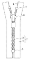
- FIG. 1 exemplarily shows a schematic front view of a metal fastener.
- the metal fastener is made of a metal that is crimped and fixed (attached) at a predetermined interval to a pair of fastener tapes 1 having a core portion 2 formed on the inner edge side and the core portion 2 of the fastener tape 1.
- the upper stoppers 4 and the lower stoppers 5 that are crimped and fixed to the core 2 of the fastener tape 1 at the upper and lower ends of the rows of the metal elements 3, and a pair of opposing elements 3
- a slider 6 slidable in the vertical direction for engaging and separating the pair of metal elements 3.
- a state in which the row of elements 3 is mounted on the core portion 2 of one fastener tape 1 is referred to as a fastener stringer, and the row of elements 3 mounted on the core portion 2 of the pair of fastener tapes 1 is engaged.
- This is called the fastener chain 7.
- the lower stop 5 may be a break-and-insert insert made up of a butterfly stick, a box stick, and a box, and the pair of fastener chains can be separated by an opening operation of the slider. Other embodiments not shown are also possible.
- the material of the metal element 3 there are no particular restrictions on the material of the metal element 3, but copper (pure copper), copper alloys (copper, brass, iron white, etc.) and aluminum alloys (Al-Cu alloys, Al-Mn alloys, Al-Si) Alloy, Al—Mg alloy, Al—Mg—Si alloy, Al—Zn—Mg alloy, Al—Zn—Mg—Cu alloy, etc.), zinc, zinc alloy, iron, iron alloy, etc. Can do.
- the plating can be performed aiming at a rust prevention effect, a crack prevention effect, and a sliding resistance reduction effect.
- the type of plating is not particularly limited and may be any one of single metal plating, alloy plating, and composite plating.
- Sn plating, Cu—Sn alloy plating, Cu—Sn—Zn alloy plating, and Sn—Co alloy are exemplified.
- Plating, Rh plating, Pd plating may be mentioned.
- Zn plating including zincate treatment
- Cu plating including copper cyanide plating, copper pyrophosphate plating, copper sulfate plating
- Cu-Zn alloy plating including brass plating
- Ni plating Ru plating, Au Plating, Co plating, Cr plating (including chromate treatment), Cr—Mo alloy plating, and the like
- the kind of plating is not limited to these, and various other metal platings can be performed according to the purpose.
- Metal fasteners can be attached to various items, and function especially as an opening / closing tool.
- the article to which the slide fastener is attached is not particularly limited, and examples thereof include daily necessaries such as clothing, bags, shoes, and miscellaneous goods, and industrial articles such as water storage tanks, fishing nets, and space suits.
- each metal element is applied to the plating solution in the plating tank for the purpose of mainly plating the surface of the element row exposed on one main surface side of the fastener chain.
- the fastener chain passes through one or more first insulating containers in which a plurality of conductive media that are in electrical contact with the cathode are flowably accommodated.
- each metal element is plated in a plating tank for the purpose of mainly plating the surface of the element row exposed on the other main surface side of the fastener chain.
- the conditions such as the composition and temperature of the plating solution may be appropriately set by those skilled in the art depending on the type of metal component to be deposited on each element, and are not particularly limited.
- the material of the conductive medium there is no particular limitation on the material of the conductive medium, but metal is common. Among metals, iron, stainless steel, copper and brass are preferable, and iron is more preferable because of high corrosion resistance and high wear resistance.
- a displacement plating film with poor adhesion is formed on the surface of the iron ball when the conductive medium comes into contact with the plating solution. This plating film is peeled off from the conductive medium during electroplating of the fastener chain and becomes a fine metal piece and floats in the plating solution. If the metal piece floats in the plating solution, it adheres to the fastener tape, so it is preferable to prevent the metal piece from floating.
- the materials for the first insulating container and the second insulating container are high-density polyethylene (HDPE), heat-resistant rigid polyvinyl chloride, polyacetal (from the viewpoint of chemical resistance, abrasion resistance, and heat resistance). POM) is preferred, and high density polyethylene (HDPE) is more preferred.
- the conductive medium is passed from the cathode to each element. Power can be supplied.
- the fastener chain passes through the first insulating container and the second insulating container in the horizontal direction, the conductive medium is conveyed in the transport direction.
- the fastener chain passes vertically through the first insulating container and the second insulating container, the conductive medium is easily collected downward.
- the fastener chain passes in the horizontal direction, it is preferable to install at least a cathode on the inner surface of the insulating container on the front side in the transport direction in which the conductive medium easily collects.
- the fastener chain can also run in an oblique direction between the horizontal direction and the vertical direction, but in this case, the place where the conductive medium easily accumulates changes depending on the inclination, running speed, number and size of the conductive medium, What is necessary is just to adjust the place which installs a cathode according to actual conditions.
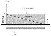
- the magnitude of the current flowing through the plurality of conductive media accommodated in the first insulating container and the second insulating container decreases as the distance from the cathode increases. Therefore, the current flowing through each element via the conductive medium also decreases as the distance from the cathode increases. For example, when one cathode is installed on the inner side surface on the leading side in the transport direction among the inner side surfaces of the insulating container, the current of the element located on the leading side is the largest as schematically shown in FIG. The current decreases toward the rear side.
- the distance in the transport direction from the cathode where the current becomes 0 when the current flowing through the cathode is I 0 (in other words, the maximum distance in the transport direction from the cathode on which the element is plated). ) Is D 0, and the distance in the transport direction from the cathode at which the current is 0 when the current flowing through the cathode is I 1 is D 1 .
- the cathode used for the first insulating container is installed at a plurality of locations on the inner surface of the first insulating container (second insulating container), so that the first It is desirable to improve the uniformity of the current flowing through the element passing through the insulating container (second insulating container).
- the uniformity of the current flowing through the element becomes high, it becomes possible to flow the maximum current that does not cause burn plating to all the elements passing through the insulating container.
- the time required to grow a plating film having the same thickness is shortened, so that the conveyance speed of the fastener chain can be increased and the production efficiency can be improved.
- the effect of equalizing the current by installing a plurality of cathodes becomes more pronounced as the plating solution has a lower conductivity.
- the current density in the element having the highest current (current flowing through the element ⁇ element surface area) is represented by D If the current density in the element having the lowest current among the elements passing through the first insulating container is D min , 0.8 ⁇ D min / D max ⁇ 1.0 is established. More preferably, 0.9 ⁇ D min / D max ⁇ 1.0, and even more preferably 0.95 ⁇ D min / D max ⁇ 1.0.
- the cathode is at least one place on the inner side surface on the front side and the rear side in the passing direction of the fastener chain among the inner side surfaces of the first insulating container (second insulating container). It is installed one by one. Thereby, the uniformity of the electric current in the conveyance direction of a fastener chain can be improved.
- the cathode is installed on each of the inner surface on the leading side in the passing direction of the fastener chain and the rear portion of the inner surface parallel to the passing direction of the fastener chain. The change in the carrying direction of the current flowing through the element in the case of being done is schematically shown.
- the cathode may be installed on the inner surface on the rear side of the first insulating container (second insulating container), but the conductive medium tends to gather on the front side and the inner surface on the rear side is made of the conductive medium. Since the possibility of contact tends to be low, it is preferable to install it at the tail part of the inner surface parallel to the passing direction of the fastener chain.
- the rear-side cathode is installed within a range of 0 to 30% from the rear side in the passage direction of the fastener chain with respect to the length of the inner surface in the passage direction of the fastener chain. More preferably, it is set within the range of 0 to 20%.
- the insulating container is long in the transport direction, it is insulative to install only one cathode on the inner surface on the leading side in the passing direction of the fastener chain and the rear part of the inner surface parallel to the passing direction of the fastener chain.
- the cathode is additionally installed at least one place on the inner surface of the first insulating container (second insulating container) parallel to the passing direction of the fastener chain.
- the number of cathodes installed on the inner surface parallel to the passing direction of the fastener chain may be determined according to the length of the insulating container in the transport direction and the desired current. When three or more cathodes are installed, it is preferable to install a plurality of cathodes at equal intervals in the passing direction of the fastener chain in order to increase the uniformity of the current flowing through the element passing through the insulating container.
- FIG. 17 shows that one cathode is installed at each of the inner side surface of the insulating container, the inner side surface on the leading side in the passing direction of the fastener chain, and the central portion and the rear portion of the inner side surface parallel to the passing direction of the fastener chain
- the change in the carrying direction of the current flowing through the element in the case of being performed is schematically shown.
- an electric current (indicated by a dotted line) caused by the cathode installed on the inner side surface on the leading side in the passing direction of the fastener chain and the tail portion of the inner side surface parallel to the passing direction of the fastener chain Even if it greatly decreases in the vicinity of the center in the passing direction of the inner fastener chain, the cathode is installed at the center of the inner surface parallel to the passing direction of the fastener chain, so that the current caused by the cathode (indicated by a one-dot chain line) ) Flows.
- the inner side parallel to the passing direction of the fastener chain is selected from the inner side surfaces of the first insulating container (second insulating container).
- the cathode installed on the side surface is preferably installed within a range of 30 to 70% from the leading side in the passing direction of the fastener chain with respect to the length of 100% in the passing direction of the fastener chain on the inner side surface. More preferably, it is set within the range of 40 to 60%.
- the cathode disposed on the inner surface parallel to the passing direction of the fastener chain is preferably disposed flush with the inner surface. (See FIG. 18). Thereby, the flow of the conductive medium is not inhibited by the cathode.
- the conductive medium can flow in each insulating container, and the conductive medium constantly changes the contact location with each element while flowing and / or rotating and / or moving up and down as the fastener chain runs. .
- the location through which current flows and the contact resistance also change constantly, so that a highly uniform plating film can be grown.
- the shape of the conductive medium is not limited as long as it is accommodated in the container in a flowable state, but is preferably spherical from the viewpoint of fluidity.
- each conductive medium vary depending on the chain width of the fastener chain, the width and pitch of the element in the slider sliding direction, but when using a fixed cell type electroplating apparatus as described later, the first insulation When the fastener chain passes through the inside of the conductive container and the second insulating container, the conductive medium enters the travel path of the fastener chain and the conductive medium is less likely to be clogged in the travel path. Preferably there is.
- the number of conductive media accommodated in the first insulating container and the second insulating container there is no particular limitation on the number of conductive media accommodated in the first insulating container and the second insulating container, but it is possible to supply power to each element of the fastener chain, in particular, the fastener chain. Even if the conductive medium moves in the direction of travel, the quantity that the conductive medium can always keep in contact with each element passing through the first insulating container and the second insulating container From the viewpoint of ensuring, it is desirable to set appropriately. On the other hand, it is preferable that an appropriate pressing pressure is applied from the conductive medium to each element of the fastener chain because it is easier for electricity to flow, but excessive pressing pressure increases the conveyance resistance and hinders the smooth conveyance of the fastener chain. .
- the fastener chain can smoothly pass through the first insulating container and the second insulating container without receiving excessive conveyance resistance.
- the conductive medium accommodated in each insulating container has three or more layers when the conductive medium is spread on the element (in other words, three times the diameter of the conductive medium).
- the above-mentioned layer thickness is preferably an amount that can be formed, and is typically an amount that can form 3 to 8 layers (in other words, a layer thickness that is 3 to 8 times the diameter of the conductive medium).
- the fastener chain passes horizontally through the first insulating container and the second insulating container, the conductive medium is placed at the head in the transport direction. Easy to move and accumulate. Then, since the fastener chain is pressed by the weight of the conductive medium accumulated at the leading portion, the conveyance resistance to the fastener chain is increased. In addition, when a current flows from the cathode to the conductive medium, the plating efficiency decreases due to a voltage drop when the cell length increases.
- the thickness of the plating film and the running speed of the fastener chain can also be adjusted by increasing or decreasing the number of two or more insulative containers connected in series.
- the inclination angle may be appropriately set according to the conveyance speed, the size and number of conductive media, etc., but when the conductive media is spherical and has an amount capable of forming 3 to 8 layers on the element, the fastener chain Even if the conductive medium moves in the traveling direction during traveling, the conductive medium is kept in contact with each element passing through the first insulating container and the second insulating container. From the viewpoint of achieving this, it is preferably 9 ° or more, and typically 9 ° or more and 45 ° or less.
- the surface of each metal element exposed mainly on the first main surface side of the fastener chain while the fastener chain passes through the first insulating container is the first.
- Power is supplied by contacting a plurality of conductive media in the insulating container.
- the first anode in a positional relationship facing the surface of each metal element exposed on the second main surface side of the fastener chain, a regular flow of cations and electrons occurs, and the fastener A plating film can be rapidly grown on the surface side of each metal element exposed on the second main surface side of the chain.
- the first anode should be installed only in a positional relationship facing the surface of each metal element exposed on the second main surface side of the fastener chain. Is preferred.
- Power is supplied by bringing the surface of the substrate into contact with the plurality of conductive media in the second insulating container.
- the second anode in a positional relationship facing the surface of each metal element exposed on the first main surface side of the fastener chain, a regular flow of cations and electrons occurs, and the fastener A plating film can be rapidly grown on the surface side of each metal element exposed on the first main surface side of the chain.
- the second anode is only used in a positional relationship facing the surface of each metal element exposed on the first main surface side of the fastener chain. It is preferable to install.
- the conductive medium in the first insulating container is configured to be able to contact the surface of each metal element exposed on the first main surface side of the fastener chain. It means that only the surface of each metal element made is brought into contact with the conductive medium in the first insulating container.
- the total number of conductive media in the second insulating container while the fastener chain passes through the second insulating container is desirable that all be configured to be able to contact the surface of each metal element exposed on the second main surface side of the fastener chain.
- the conductive medium in the second insulating container is configured to be able to come into contact with the surface of each metal element exposed on the second main surface side of the fastener chain. It means that only the surface of each metal element made is brought into contact with the conductive medium in the second insulating container.
- the shortest distance between the surface of each metal element exposed on the second main surface side of the fastener chain and the first anode, and the surface of the metal element exposed on the first main surface side of the fastener chain and the second can be efficiently plated on each metal element, and plating on unnecessary portions (for example, a conductive medium) can be suppressed. By increasing the plating efficiency, the maintenance cost, chemical cost, and electricity cost of the conductive medium can be saved.
- the shortest distance between each metal element and the anode is preferably 10 cm or less, more preferably 8 cm or less, still more preferably 6 cm or less, and even more preferably 4 cm or less. At this time, it is desirable from the viewpoint of plating efficiency that the first anode and the second anode are extended in parallel to the fastener chain conveying direction.
- An electroplating apparatus is, in one embodiment, A plating tank capable of containing a plating solution; A first anode disposed in a plating bath; One or two or more first insulating containers disposed in a plating tank and in which a plurality of conductive media are flowably accommodated in electrical contact with the cathode; Is provided.
- the first insulating container mainly contacts the surface of each metal element exposed on the first main surface side of the fastener chain with the plurality of conductive media in the first insulating container.
- the fastener chain is configured to be able to pass through the first insulating container.
- the first anode faces the surface of each metal element exposed on the second main surface side of the fastener chain when the fastener chain passes through the first insulating container. It can be installed in a positional relationship.
- the surface of the element row exposed on the one main surface side of the fastener chain can be mainly plated.
- the electroplating apparatus is another embodiment, A second anode disposed in the plating tank; One or two or more second insulating containers, which are disposed in the plating tank and in which a plurality of conductive media are flowably accommodated in a state of being in electrical contact with the cathode; Is further provided.
- the second insulating container mainly contacts the surface of each metal element exposed on the second main surface side of the fastener chain with the plurality of conductive media in the second insulating container.
- the fastener chain is configured to be able to pass through the second insulating container.
- the second anode faces the surface of each metal element exposed on the first main surface side of the fastener chain when the fastener chain passes through the second insulating container. Installed in a positional relationship. According to this embodiment, it is possible to plate the surfaces of the element rows exposed on both main surface sides of the fastener chain.
- FIGS. 2 to 4 schematically show the structure of an insulating container (can be used for both the first and second insulating containers) in one configuration example of a fixed cell plating apparatus.
- FIG. 2 is a schematic cross-sectional view of the insulating container of the fixed cell plating apparatus as viewed from the direction facing the fastener chain conveyance direction.
- FIG. 3 is a schematic cross-sectional view taken along line AA ′ of the insulating container shown in FIG.
- FIG. 4 is a schematic cross-sectional view taken along the line BB ′ when the conductive medium and the fastener chain are removed from the insulating container shown in FIG.
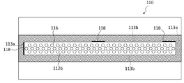
- the insulating container 110 includes a passage 112 that guides the travel path of the fastener chain 7 and a housing portion 113 that houses a plurality of conductive media 111 in a flowable manner.
- the passage 112 has a fastener chain inlet 114, a fastener chain outlet 115, and a road surface 112 a on the side opposite to one (first or second) main surface side of the fastener chain 7.
- the plating solution can communicate with the one or two or more openings 117 enabling access and the road surface 112b on the side opposite to the other (second or first) main surface side of the fastener chain 7 and a current flows. And a plurality of apertures 116 that make it possible.
- a guide groove 120 for guiding the transport direction of the element 3 may be provided on the road surface 112b along the transport direction.
- the length in the chain width direction is W 2 and the diameter of the conductive medium 111 is D.
- the chain width refers to the width of the meshed elements as defined in JIS 3015: 2007.
- the diameter of the conductive medium is defined as the diameter of a true sphere having the same volume as the conductive medium to be measured.
- the fastener chain 7 entering the insulating container 110 from the entrance 114 travels in the direction of the arrow in the passage 112 and exits from the exit 115. While the fastener chain 7 passes through the passage 112, the plurality of conductive media 111 held in the accommodating portion 113 can contact the surface of each element 3 exposed to one main surface side of the fastener chain 7 through the opening 117. is there. However, there is no opening through which the conductive medium 111 can access the surface of each element 3 exposed on the other main surface side of the fastener chain 7. For this reason, the plurality of conductive media 111 held in the housing portion 113 cannot contact the surface of each element 3 exposed on the other main surface side of the fastener chain 7.
- the conductive medium 111 moves to the top in the conveying direction and is easily collected by being dragged by the fastener chain 7 traveling in the passage 112. However, if the conductive medium 111 is excessively accumulated, the conductive medium 111 is clogged at the top, and the fastener chain 7 is Since it is strongly pressed, the conveyance resistance of the fastener chain 7 is increased. For this reason, as shown in FIG. 3, the plurality of conductive media 111 accommodated in the insulating container 110 is gravity-induced by providing the outlet 115 higher than the inlet 114 and ascending and tilting the passage 112. Therefore, the conveyance resistance can be reduced. It is also possible to provide an outlet 115 vertically above the inlet 114 so that the conveying direction of the fastener chain 7 is vertically upward. This makes it easy to control the conveying resistance and also requires the advantage of a small installation space. It is done.
- a plate-like cathode 118 is installed on the inner side surface 113 a on the leading side in the transport direction among the inner surface of the accommodating portion 113.
- the plurality of conductive media 111 can be in electrical contact with the plate cathode 118. Further, while the fastener chain 7 is passing through the passage 112, the plurality of conductive media 111 can be in electrical contact with the surface of each element 3 exposed on one main surface side of the fastener chain 7. When at least a part of the plurality of conductive media 111 is in electrical contact with both of the conductive media 111 to create an electrical path, the fastener chain 7 passes through the passage 112 and is connected to each element 3. Power supply is possible.
- the fastener chain 7 is electroplated while immersed in a plating solution. While the fastener chain 7 passes through the passage 112 of the insulating container 110, the plating solution enters the passage 112 through the opening 116, and can contact each element 3.
- the anode 119 on the side opposite to the other (second or first) main surface side of the fastener chain 7, the cations in the plating solution efficiently reach the other main surface side of the fastener chain.
- the plating film can be rapidly grown on the surface of each element 3 exposed on the main surface side.
- each opening 116 formed in the road surface 112 b is provided so as not to be caught with the fastener chain 7 traveling in the passage 112.
- each opening 116 is preferably a circular hole, for example, a circular hole having a diameter of 1 to 3 mm.
- the opening 116 formed in the road surface 112b is provided so that electricity flows with high uniformity throughout the element 3 of the fastener chain 7 running in the passage 112, in order to obtain a highly uniform plating film.
- the ratio of the area of the opening 116 to the area including the opening 116 of the road surface 112b (hereinafter referred to as an opening ratio) is preferably 40% or more, and more preferably 50% or more.
- the aperture ratio is preferably 60% or less for reasons of securing strength.
- the fastener chain 7 travels in the passage 112, it is preferable that the plurality of conductive media 111 do not contact the fastener tape 1. This is because when a plurality of conductive media 111 come into contact with the fastener tape 1, the conveyance resistance of the fastener chain is increased. Therefore, the opening 117 is preferably installed at a place where the plurality of conductive media 111 cannot contact the fastener tape.
- the insulating container is viewed from the direction facing the conveying direction of the fastener chain (see FIG. 2), the gaps C1 and C2 in the chain width direction from both side walls of the opening 117 to both ends of the element 3 are respectively in the conductive media 111. More preferably, it is equal to or less than the radius.
- the gaps C1 and C2 are preferably 0 or more, and more preferably greater than 0.
- the radius of the conductive medium is defined as a radius of a true sphere having the same volume as the conductive medium to be measured.
- the distance between the road surface 112a and the road surface 112b is preferably shorter than the diameter of the conductive medium so that the conductive medium does not enter the passage 112. This is because if the conductive medium enters the passage 112, the conveyance resistance is remarkably increased, and the conveyance of the fastener chain 7 becomes difficult.
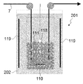
- FIGS. 5 to 10 show some examples of the entire configuration of the fixed cell type electroplating apparatus.
- the fastener chain 7 is transported in the direction of the arrow under tension in the plating tank 201 containing the plating solution 202.
- the tension is preferably a load of 0.1N to 0.2N.
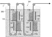
- the fastener chain 7 proceeds vertically downward to the bottom of the plating tank 201 after entering the plating solution 202. After reaching the bottom, it is reversed and passes through the first insulating container 110a and the second insulating container 110b in the vertical direction in order, and exits from the plating solution 202.
- the first insulating container 110 a and the second insulating container 110 b are provided in opposite directions with respect to each main surface of the fastener chain 7.
- the insides of the first insulating container 110a and the second insulating container 110b are each divided into two sections A and B connected in series. While the fastener chain 7 passes through the first insulating container 110a, the surface of each metal element exposed on one main surface side of the fastener chain 7 is plated, and the fastener chain 7 passes through the second insulating container 110b.
- the surface of each metal element exposed on the other main surface side of the chain 7 is plated. According to this embodiment, double-sided plating is possible with a single plating tank, and installation space can be reduced.
- An insulating partition plate 121 for electrical interruption is provided between the first insulating container 110a and the second insulating container 110b so as not to be affected by each other.
- the material of the partition plate 121 is not particularly limited as long as it is an insulator, but may be made of a resin such as a vinyl chloride resin.
- the fastener chain 7 proceeds vertically downward to the bottom of the plating tank 201 after entering the plating solution 202. After reaching the bottom, it is inverted and passes through the first insulating container 110a vertically upward. The fastener chain 7 once exits from the plating solution 202, then reverses, enters the plating solution 202 again, and proceeds vertically downward to the bottom of the plating tank 201. After reaching the bottom, it is reversed again, passes vertically through the second insulating container 110b, and leaves the plating solution 202.
- the first insulating container 110 a and the second insulating container 110 b are provided in opposite directions with respect to each main surface of the fastener chain 7.
- the insides of the first insulating container 110a and the second insulating container 110b are each divided into two sections A and B connected in series. While the fastener chain 7 passes through the first insulating container 110a, the surface of each metal element exposed on one main surface side of the fastener chain 7 is plated, and the fastener chain 7 passes through the second insulating container 110b.
- the surface of each metal element exposed on the other main surface side of the chain 7 is plated. According to this embodiment, double-sided plating is possible with one plating tank.
- the fastener chain 7 enters the plating solution 202 and then proceeds vertically downward to the bottom of the plating tank 201. After reaching the bottom, it is inverted and passes through the first set of the first insulating container 110a and the second insulating container 110b vertically upward. The fastener chain 7 once exits from the plating solution 202, then reverses, enters the plating solution 202 again, and proceeds vertically downward to the bottom of the plating tank 201. After reaching the bottom, it is inverted again, passes vertically through the second set of the first insulating container 110a and the second insulating container 110b, and leaves the plating solution 202.
- the first insulating container 110 a and the second insulating container 110 b are provided in opposite directions with respect to the main surfaces of the fastener chain 7. While the fastener chain 7 passes through the first insulating container 110a, the surface of each metal element exposed on one main surface side of the fastener chain 7 is plated, and the fastener chain 7 passes through the second insulating container 110b. The surface of each metal element exposed on the other main surface side of the chain 7 is plated.
- An insulating partition plate 121 for electrical interruption is provided between the first insulating container 110a and the second insulating container 110b so as not to be affected by each other. Furthermore, a partition plate 121 for electrical interruption is provided between the first set and the second set so as not to be affected by each other. According to this embodiment, double-sided plating is possible with one plating tank.
- the plating tank 201 is divided into a first plating tank 201a, a second plating tank 201b, and a third plating tank 201c.
- the fastener chain 7 enters the plating solution 202a of the first plating tank 201a, it proceeds vertically downward to the bottom of the first plating tank 201a. After reaching the bottom, it is inverted, passes vertically through the two first insulating containers 110a arranged in series, and exits the plating solution 202a.
- the fastener chain 7 enters the plating solution 202b from the inlet 204 provided on the side wall of the second plating tank 201b, and passes obliquely upward through the three second insulating containers 110b arranged in series.
- the fastener chain 7 enters the plating solution 202c of the third plating tank 201c, it proceeds vertically downward to the bottom of the third plating tank 201c. After reaching the bottom, it is inverted, passes vertically through the two first insulating containers 110a arranged in series, and exits the plating solution 202c.
- the plating solution overflows from the inlet 204 and the outlet 205 of the second plating tank 201b.
- the overflowed plating solution is collected in the storage tank 203 through the return pipe 210 and then supplied again to the second plating tank 201b through the feed pipe 212 by the circulation pump 208.
- a heater 209 may be installed in the storage tank 203 to heat the internal plating solution.
- the first insulating container 110 a and the second insulating container 110 b are provided in opposite directions with respect to the main surfaces of the fastener chain 7. While the fastener chain 7 passes through the first insulating container 110a, the surface of each metal element exposed on one main surface side of the fastener chain 7 is plated, and the fastener chain 7 passes through the second insulating container 110b. The surface of each metal element exposed on the other main surface side of the chain 7 is plated.
- the plating tank 201 is divided into a first plating tank 201a and a second plating tank 201b.
- the fastener chain 7 enters the plating solution 202a from the inlet 206 provided on the side wall of the first plating tank 201a, passes obliquely upward through the three first insulating containers 110a arranged in series, It exits from the outlet 207 provided in the side wall of the plating tank 201a.
- the outlet 207 is higher than the inlet 206.
- the fastener chain 7 enters the plating solution 202b of the second plating tank 201b, it proceeds vertically downward to the bottom of the second plating tank 201b. After reaching the bottom, it is inverted, passes vertically through the three second insulating containers 110b arranged in series, and exits the plating solution 202b.
- the plating solution overflows from the inlet 206 and the outlet 207 of the first plating tank 201a.
- the overflowed plating solution is collected in the storage tank 203 through the return pipe 210 and then supplied again to the first plating tank 201a through the feed pipe 212 by the circulation pump 208.
- a heater 209 may be installed in the storage tank 203 to heat the internal plating solution.
- the first insulating container 110 a and the second insulating container 110 b are provided in opposite directions with respect to the main surfaces of the fastener chain 7. While the fastener chain 7 passes through the first insulating container 110a, the surface of each metal element exposed on one main surface side of the fastener chain 7 is plated, and the fastener chain 7 passes through the second insulating container 110b. The surface of each metal element exposed on the other main surface side of the chain 7 is plated.
- the plating tank 201 is divided into a first plating tank 201a and a second plating tank 201b.
- the fastener chain 7 enters the plating solution 202a from an inlet 204 provided on the side wall of the first plating tank 201a, passes obliquely upward through the three first insulating containers 110a arranged in series, It exits from the outlet 205 provided in the side wall of the plating tank 201a.
- the outlet 205 is higher than the inlet 204.
- the fastener chain 7 changes its direction, enters the plating solution 202b from the inlet 206 provided on the side wall of the second plating tank 201b installed above the first plating tank 201a, and is arranged in series. It passes through the three second insulating containers 110b obliquely upward and exits from an outlet 207 provided on the side wall of the second plating tank 201b.
- the plating solution overflows from the inlet 204 and the outlet 205 of the first plating tank 201a.
- the overflowed plating solution is collected in the storage tank 203 through the return pipe 210a, and then supplied again to the first plating tank 201a through the feed pipe 212a by the circulation pump 208. Further, the plating solution overflows from the inlet 206 and the outlet 207 of the second plating tank 201b.
- the overflowed plating solution is collected in the storage tank 203 through the return pipe 210b and then supplied again to the second plating tank 201b through the feed pipe 212b by the circulation pump 208.
- the return pipe 214 for adjusting the level of the plating solution 202a is adjusted in the first plating tank 201a, and the level of the plating solution 202b is adjusted in the second plating tank 201b.
- Return pipes 216 are provided for preventing the plating solution from overflowing from the respective plating tanks (201a, 201b).
- the first insulating container 110a and the second insulating container 110b are provided in opposite directions with respect to the main surfaces of the fastener chain 7. While the fastener chain 7 passes through the first insulating container 110a, the surface of each metal element exposed on one main surface side of the fastener chain 7 is plated, and the fastener chain 7 passes through the second insulating container 110b. The surface of each metal element exposed on the other main surface side of the chain 7 is plated.
- the amount of current flowing to the cathode of each fixed cell (first insulating container 110a and second insulating container 110b) arranged in series while the fastener chain 7 is running is set.
- the plating film thickness can be changed for each element 3.
- the plating appearance of a mottled pattern (different film thickness) can be imparted to the fastener chain 7.
- the plating tanks in which the first insulating container 110a and the second insulating container 110b are accommodated are separated. For this reason, although both can be immersed in the plating solution of the same composition, by arranging both in the plating tank containing the plating solution of a different composition, one main surface and the other main surface are made into a different color. Can be plated.
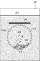
- FIG. 11 is a schematic diagram for explaining the principle of preferentially plating the upper surface of the fastener chain in a rotating barrel type electroplating apparatus.
- FIG. 12 is a schematic diagram for explaining the principle of preferentially plating the lower surface of the fastener chain in a rotating barrel type electroplating apparatus.
- FIG.11 and FIG.12 the mode when a rotation barrel is seen from the direction which faces the conveyance direction of a fastener chain is drawn.
- a plurality of conductive media 311 are flowably accommodated in the first rotating barrel 310 a immersed in the plating solution 202 in the plating tank 201, and the plurality of conductive media 311 are the first ones.
- the surface of each element 3 exposed on the lower surface side of the fastener chain 7 is filled to a height that preferentially contacts the surface of each element 3 exposed on the upper surface side of the fastener chain 7. Yes.
- the specific height can be adjusted as appropriate in consideration of the diameter and number of the conductive media 311, the height of the fastener chain 7, and the like.
- An opening 318 large enough to prevent the conductive medium 311 from passing through is provided on the wall surface of the first rotating barrel 310a so that the plating solution can enter and exit the first rotating barrel 310a through the opening 318. It has become. While the fastener chain 7 passes through the first rotating barrel 310a in a direction parallel to the rotation axis, the plurality of conductive media 311 are viewed in cross section of the first rotating barrel 310a as the first rotating barrel 310a rotates. While moving on the inner surface of the circular shape, at least a part of the conductive medium 311 contacts the cathode 317 installed in the first rotating barrel 310a, and the fastener is passing through the first rotating barrel 310a.
- At least a part of the conductive medium 311 can come into contact with the surface of each element 3 exposed on the lower surface side of the chain 7.
- the fastener chain 7 passes through the first rotating barrel 310a, Power can be supplied to the element 3.
- the anode 316 is installed at a position facing the surface of each element 3 exposed on the upper surface side of the fastener chain 7. Thereby, the cation in the plating solution can efficiently reach the upper surface side of the fastener chain 7, and the plating film can be rapidly grown on the surface side of each element 3 exposed on the upper surface side.
- the plurality of conductive media 311 in the first rotating barrel 310a slides down or rolls down on the inner surface of the first rotating barrel 310a under the influence of gravity, so that each element exposed on the upper surface side of the fastener chain 7 is exposed. It is difficult to contact the surface of 3.
- a plurality of conductive media 311 are flowably accommodated in the second rotating barrel 310b immersed in the plating solution 202 in the plating tank 201.
- the wall surface of the second rotating barrel 310b is provided with a plurality of openings 318 large enough to prevent the conductive medium 311 from passing through, and the plating solution can enter and exit the second rotating barrel 310b through the openings 318. It is like that.
- each element 3 exposed on the upper surface side of the fastener chain 7 is more than the surface of the element 3 exposed on the lower surface side of the fastener chain 7 in which a large number of conductive media 311 accommodated in the second rotating barrel 310b
- the second rotating barrel 310b has at least one guide member 312 (in FIG. 12, etc.) protruding inwardly (in the direction of the rotation axis in FIG. 12) from the inner surface of the circular shape in cross section. 8 guide plates extending in a direction parallel to the rotation axis at intervals.
- the plurality of conductive media 311 are supported by the guide member 312 on the inner surface of the second rotating barrel 310b as the second rotating barrel 310b rotates. You can climb halfway. As the rotating operation of the second rotating barrel 310b proceeds, the conductive medium 311 that cannot be supported by the guide member 312 flows to the inside of the second rotating barrel 310b.
- At least a part of the conductive medium 311 that is flowing inward is in contact with the cathode 317 installed in the second rotating barrel 310b and is passing through the second rotating barrel 310b in a direction parallel to the rotation axis. At least a part of the conductive medium 311 can come into contact with the surface of each element 3 exposed on the upper surface side of the fastener chain 7. When at least a part of the plurality of conductive media is in electrical contact with both of the conductive media to create an electrical path, each element 3 is being moved while the fastener chain 7 passes through the second rotating barrel 310b. Can be fed.
- the anode 316 is installed at a position facing the surface of each element 3 exposed on the lower surface side of the fastener chain 7. Thereby, the cation in the plating solution can efficiently reach the lower surface side of the fastener chain 7, and the plating film can be rapidly grown on the surface side of each element 3 exposed on the lower surface side.
- FIG. 13 shows an example of the overall configuration of a rotating barrel type electroplating apparatus.
- the fastener chain 7 enters the plating solution 402 from the inlet 406 provided on the side wall of the plating tank 401 while being conveyed in the direction of the arrow, and is linear in the horizontal direction from the inlet 314a to the outlet 315a of the first rotating barrel 310a. To pass through. While passing through the first rotating barrel 310a, the surface of each element 3 exposed mainly on the upper surface side of the fastener chain is plated.
- the fastener chain 7 passes straight from the inlet 314b to the outlet 315b of the second rotating barrel 310b connected in series to the first rotating barrel 310a in the horizontal direction, and is provided on the side wall of the plating tank 401. Take exit 407. While passing through the second rotating barrel 310b, the surface of each element 3 exposed mainly on the lower surface side of the fastener chain 7 is plated. Between the first rotary barrel 310a and the second rotary barrel 310b, an insulating partition plate 321 for electrical interruption is provided so as not to be affected by each other.
- the plating solution overflows from the inlet 406 and the outlet 407 of the plating tank 401.
- the overflowed plating solution is collected in the storage tank 403 through the return pipe 410 and then supplied again to the plating tank 401 through the feed pipe 412 by the circulation pump 408.
- a heater 409 may be installed in the storage tank 403 to heat the internal plating solution.
- Both of the second rotating barrels 310b for growing the plating film on the surface of the fastener chain are used, but it is possible to plate both surfaces of the fastener chain by using only one of them. For example, a method is conceivable in which the fastener chain 7 that has passed through the first rotating barrel 310a is turned upside down and then passed through another first rotating barrel 310a.
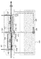
- the electroplating apparatus shown in FIG. 14 was constructed, and electroplating was continuously performed on the fastener chain being conveyed.
- an insulating container 110 containing a large number of conductive media 111 is disposed in a plating tank 201 containing a plating solution 202.
- a cathode 118 is installed at the center of the inside of the insulating container 110, and the conductive medium 111 is in electrical contact with the cathode.
- the insulating container 110 has anodes 119 on the front and rear inner surfaces with respect to the traveling direction of the fastener chain 7.
- the conductive medium randomly contacts the elements exposed on both main surface sides of the fastener chain 7, so that the plating film is applied to the surface of the element. Will grow.
- the plating test conditions are as follows. -Fastener chain specifications: YKK model 5RG chain (chain width: 5.75 mm, element material: red) ⁇ Plating solution: 5 L, composition: plating solution for Sn—Co alloy plating ⁇ Conductive medium: stainless steel sphere, diameter 4.5 mm, 2700 pieces ⁇ Current density: 5 A / dm 2 The current density was a value obtained by dividing the current value (A) of the rectifier by the total surface area (both sides) of the elements in the glass container and the total surface area (dm 2 ) of the stainless sphere. The reason why the surface area of the stainless steel sphere is taken into account is that the plating also adheres to the stainless steel sphere. ⁇ Retention time in plating solution: 7.2 seconds ⁇ Conveying speed: 2.5 m / min ⁇ Insulating container: Glass beaker
- Example 1 Fixed cell plating apparatus
- An insulating container having the structure shown in FIGS. 2 to 4 was produced with the following specifications.
- Insulating container made of acrylic resin
- Inclination angle 9 °
- Opening 116 Opening ratio 54%, circular holes with a diameter of 2 mm, staggered arrangement Clearances C1, C2: 2 mm , Width W 2: 10mm
- the electroplating apparatus shown in FIG. 10 was constructed using the insulating container, and electroplating was continuously performed on the fastener chain being conveyed.
- plating time min
- deposition rate ⁇ m / ((A / dm 2 ) ⁇ min)
- the current density A / dm 2
- the plating thickness is an average value of actually measured values obtained by observing a plurality of cross sections
- the plating time is the time required for each element to pass through the three insulating containers (plating time for each side).
- Plating time 14.4 seconds
- Conveying speed 2.5 m / min ⁇ Minimum distance between each element and anode: 3 cm
- Example 2 Fixed cell plating apparatus
- Electroplating was continuously performed on the fastener chain being conveyed in the same manner as in Example 1 except that the plating test conditions were as follows.
- -Fastener chain specifications YKK model 5RG chain (chain width: 5.75 mm, element material: red)
- -Plating solution 120 L
- Composition Plating solution for copper pyrophosphate plating-Current density: 13.5
- a / dm 2 Plating thickness precipitation rate ⁇ current density ⁇ plating time.
- plating time min
- deposition rate ⁇ m / ((A / dm 2 ) ⁇ min)
- the current density A / dm 2
- the plating thickness is an average value of actually measured values obtained by observing a plurality of cross sections
- the plating time is the time required for each element to pass through the three insulating containers (plating time for each side).
- ⁇ Plating time 30.0 seconds
- Conveying speed 1.2 m / min
- Minimum distance between each element and anode 3 cm
- Example 3 Fixed cell type plating apparatus
- Electroplating was continuously performed on the fastener chain being conveyed in the same manner as in Example 1 except that the plating test conditions were as follows.
- -Fastener chain specifications YKK model 5RG chain (chain width: 5.75 mm, element material: red)
- Current density: 25.0 A / dm 2 Plating thickness precipitation rate ⁇ current density ⁇ plating time.
- plating time min
- deposition rate ⁇ m / ((A / dm 2 ) ⁇ min)
- the current density A / dm 2
- the plating thickness is an average value of actually measured values obtained by observing a plurality of cross sections
- the plating time is the time required for each element to pass through the three insulating containers (plating time for each side).
- Plating time 36.0 seconds
- Conveying speed 1.0 m / min
- Minimum distance between each element and anode 3 cm
- Example 4 Fixed cell plating apparatus
- Electroplating was continuously performed on the fastener chain being conveyed in the same manner as in Example 1 except that the plating test conditions were as follows.
- -Fastener chain specifications YKK model 5RG chain (chain width: 5.75 mm, element material: red)
- Plating solution 120 L
- Composition Plating solution for non-cyan Cu—Sn alloy plating
- Current density 4.0
- a / dm 2 Plating thickness precipitation rate ⁇ current density ⁇ plating time.
- plating time min
- deposition rate ⁇ m / ((A / dm 2 ) ⁇ min)
- the current density A / dm 2
- the plating thickness is an average value of actually measured values obtained by observing a plurality of cross sections
- the plating time is the time required for each element to pass through the three insulating containers (plating time for each side).
- Plating time 14.4 seconds
- Conveying speed 2.5 m / min ⁇ Minimum distance between each element and anode: 3 cm
- Example 5 Relationship between distance from cathode and maximum plating distance
- An insulating container having the structure shown in FIGS. 2 to 4 was produced with the following specifications.
- the cathode was provided only on the inner surface on the leading side in the passing direction of the fastener chain.
- the plating test conditions are as follows. -Fastener chain specifications: YKK model 5RG chain (chain width: 5.75 mm, element material: red) -Plating solution: 120 L, composition: plating solution for nickel plating-Fastener chain transportation was stopped, and a current of 2 A was applied to the cathode for 10 seconds while the fastener chain in the insulating container was swung left and right.
- the distance from the cathode to the furthest element among the elements that were visually confirmed to be adhered was 12 cm.
- the distance from the cathode to the furthest element among the elements that were visually confirmed to adhere to the plating was measured respectively. The results are shown in Table 2.
- Example 6 Improvement of plating efficiency by installing a plurality of cathodes
- the insulating container same as Example 5 was produced except having provided the cathode in a total of three places of 14 cm away (point C).
- the plating test conditions are as follows. -Fastener chain specifications: YKK model 5RG chain (chain width: 5.75 mm, element material: red) ⁇ Plating solution: 120L, composition: plating solution for nickel plating ⁇ Conveyance of fastener chain is stopped, and the current value of each cathode is set to the values shown in Table 3 while the fastener chain in the insulating container is swung left and right. Then, plating was performed for the time shown in Table 3.
- Example 5 From the comparison with Example 5, it can be understood that the installation of a plurality of cathodes increases the area of elements that can be plated while suppressing the current value to each cathode. In addition, even if the total current value is the same, the maximum current value in each cathode is less than half, so that it is possible to plate with a total current value more than twice as compared with the case where the cathode is installed in one place. Understandable. This suggests that plating is possible even when the travel speed of the fastener chain is doubled or more.
Abstract
The purpose of the present invention is to provide an electroplating method for a metal fastener, the method enabling each element of a metal fastener to be easily plated with high uniformity. Provided is an electroplating method for a fastener chain having a row of metal elements. The method includes a step in which, in a state where each metal element is in contact with a plating liquid in a plating tank, the fastener chain passes through at least one first insulated receptacle in which a plurality of conductive mediums which are in electrical contact with a negative electrode are flowably accommodated. While the fastener chain passes through the first insulated receptacle, principally the surface of the metal elements which is exposed on a first main-surface side of the fastener chain is electrified by coming into contact with the plurality of conductive mediums in the first insulated receptacle. A first positive electrode is disposed in a positional relationship such that the first positive electrode faces the surface of the metal elements which are exposed on a second main-surface side of the fastener chain.
Description
本発明は金属ファスナー用電気めっき方法に関する。また、本発明は金属ファスナー用電気めっき装置に関する。
The present invention relates to an electroplating method for metal fasteners. The present invention also relates to an electroplating apparatus for metal fasteners.
スライドファスナーの中には、エレメント列が金属でできているものがあり、このようなスライドファスナーは一般に“金属ファスナー”と総称される。金属ファスナーは銅合金やアルミニウム合金を使用することが多く、金属の色味や素材感を活かしたデザインに向いている。最近では、金属ファスナーの意匠に対するユーザからの要望が多様化しており、用途に応じて各種色調の提供が求められるようになってきている。
Some slide fasteners have element rows made of metal, and such slide fasteners are generally collectively referred to as “metal fasteners”. Metal fasteners often use copper alloy or aluminum alloy, and are suitable for designs that take advantage of the color and texture of the metal. Recently, the demands from users for the design of metal fasteners have been diversified, and provision of various color tones has been required depending on the application.
金属製品の色調に変化を与える方法の一つとしては電気めっき法が挙げられる。電気めっき法においては、被めっき物をめっき液に浸漬し、通電することで被めっき物の表面にめっき被膜を形成する。
One method of changing the color tone of metal products is electroplating. In the electroplating method, a plating film is formed on the surface of the object to be plated by immersing the object to be plated in a plating solution and energizing it.
小物製品の電気めっき法としては、バレル内に被めっき物を入れ、そのバレルをめっき液中に投入し、バレルを回転させながら電気めっきを行うバレルめっきが多用されている(例:特開2004-100011号公報、特開2008-202086号公報、特許第3087554号公報、特許第5063733号公報)。
As an electroplating method for small products, barrel plating is often used in which an object to be plated is placed in a barrel, the barrel is placed in a plating solution, and electroplating is performed while rotating the barrel (for example, Japanese Patent Application Laid-Open No. 2004-2004). -100011, JP 2008-202086, JP 3087554, JP 5063733).
また、長尺製品の電気めっき法としては、めっき槽内で長尺製品を連続的に走行させながら電気めっきする方法が知られている(例:特開2004-76092号公報、特開平5-239699号公報、特開平8-209383号公報)。
Further, as an electroplating method for a long product, a method of performing electroplating while continuously running the long product in a plating tank is known (for example, Japanese Patent Application Laid-Open No. 2004-76092 and Japanese Patent Application Laid-Open No. Hei 5-). No. 239699, JP-A-8-209383).
しかし、上記に挙げた方法は金属ファスナーの特殊性が考慮されていない。金属ファスナーにおいては、隣接するエレメント同士が電気的に接続されていないため、上記のような方法では各エレメントに均一に電気めっきを行うのは困難である。このため、金属ファスナーをめっきするために、エレメント同士が予め電気的に接続した状態にファスナーチェーンを作製し、このファスナーチェーンに連続的に電気めっきする方法が提案されている。例えば、特許第2514760号公報では、ファスナーテープのエレメント取付部内に導電糸を編み込むことでエレメント同士が電気的に接続された状態のファスナーチェーンを作製することが提案されている。
However, the above-mentioned methods do not consider the special characteristics of metal fasteners. In the metal fastener, since adjacent elements are not electrically connected to each other, it is difficult to uniformly perform electroplating on each element by the above method. For this reason, in order to plate a metal fastener, a method has been proposed in which a fastener chain is produced in a state where elements are electrically connected in advance, and the fastener chain is continuously electroplated. For example, in Japanese Patent No. 2514760, it is proposed to produce a fastener chain in which elements are electrically connected by weaving conductive yarn into an element attachment portion of a fastener tape.
特許第2514760号公報に記載の方法の場合、エレメント列全体を同時に通電し、連続的に電気めっきできるが、導電糸は高価であり、また、金属の導電糸を織り込むためにテープ作製や染色において導電糸の切断や金属の溶解など起こり易く、生産性が悪いという問題がある。導電糸を使用することなく金属ファスナーを電気めっきする方法としては、めっき槽中で円筒形の給電ロール表面に金属ファスナーの個々のエレメントを接触させながら金属ファスナーを搬送する連続めっき法が考えられる。しかしながら、このような方法では給電ロールとエレメントの接触が不均一となり易いため、めっき被膜の均一性を得るためには給電ロールとの接触を多数繰り返す必要がある。よって、めっき装置が大がかりとなり、装置価格も高額となる。
In the case of the method described in Japanese Patent No. 2514760, the entire element array can be energized simultaneously and continuously electroplated. However, the conductive yarn is expensive, and in order to weave the metal conductive yarn, in tape production and dyeing There is a problem that the conductive yarn is likely to be cut and the metal is melted, resulting in poor productivity. As a method for electroplating metal fasteners without using conductive yarns, a continuous plating method in which the metal fasteners are conveyed while contacting individual elements of the metal fasteners on the surface of a cylindrical power supply roll in a plating tank is conceivable. However, in such a method, the contact between the power supply roll and the element is likely to be non-uniform, and therefore it is necessary to repeat the contact with the power supply roll many times in order to obtain the uniformity of the plating film. Therefore, the plating apparatus becomes a large scale and the apparatus price becomes high.
そこで、本発明は、エレメント同士が予め電気的に接続されていなくても、金属ファスナーの個々のエレメントに対して簡便に高い均一性でめっきすることができる金属ファスナー用電気めっき方法及び装置を提供することを主たる課題とする。
Therefore, the present invention provides an electroplating method and apparatus for metal fasteners that can easily and highly uniformly plate individual elements of metal fasteners even if the elements are not electrically connected in advance. The main task is to do.
金属ファスナーは、一対の長尺ファスナーテープが各ファスナーテープの対向し合う側縁に固定された金属製エレメントの列を噛み合わせてできるファスナーチェーンと呼ばれる中間製品を経て製造されるのが一般的である。このファスナーチェーンを所定の長さで切断し、スライダー、上止め、下止め等の各種部品を取り付けることで金属ファスナーが完成する。
Metal fasteners are generally manufactured through an intermediate product called a fastener chain, which is formed by engaging a row of metal elements in which a pair of long fastener tapes are fixed to opposite side edges of each fastener tape. is there. A metal fastener is completed by cutting the fastener chain at a predetermined length and attaching various parts such as a slider, an upper stopper, and a lower stopper.
前記課題を解決するため、本発明者等が鋭意検討したところ、ファスナーチェーンをめっき液中で走行させている間に、ファスナーチェーンに固定されているそれぞれの金属製エレメントを流動可能に収容された複数の導電性媒体に接触させ、該導電性媒体を介して通電する手法が有効であることを見出した。そして、金属製エレメントを導電性媒体に接触させる際には、導電性媒体はファスナーチェーンの一方の主表面側に配置しつつ他の主表面側には導電性媒体を配置せず金属製エレメントとめっき液との接触を確保することで、他の主表面側にめっき被膜が効率的に成長することを見出した。すなわち、金属製エレメントはファスナーチェーンの片面毎にめっきすることで個々のエレメントへの給電を確実に行うことができることを見出した。
In order to solve the above-mentioned problems, the present inventors diligently studied. While the fastener chain was running in the plating solution, each metal element fixed to the fastener chain was accommodated in a flowable manner. It has been found that a technique of contacting a plurality of conductive media and energizing through the conductive media is effective. When the metal element is brought into contact with the conductive medium, the conductive medium is disposed on one main surface side of the fastener chain, while the conductive medium is not disposed on the other main surface side. It has been found that the plating film grows efficiently on the other main surface side by ensuring the contact with the plating solution. That is, the present inventors have found that the metal elements can be surely supplied with power to each element by plating each side of the fastener chain.
上記知見を基礎として完成した本発明は以下のように例示される。
[1]
金属製エレメントの列を有するファスナーチェーンの電気めっき方法であって、
各金属製エレメントがめっき槽中のめっき液に接触した状態で、陰極(118、317)に電気的に接触した複数の導電性媒体(111、311)が流動可能に収容された一つ又は二つ以上の第一の絶縁性容器(110a、310a)内を該ファスナーチェーンが通過する工程を含み、
該ファスナーチェーンが第一の絶縁性容器(110a、310a)内を通過中に主として該ファスナーチェーンの第一の主表面側に露出した各金属製エレメントの表面を第一の絶縁性容器(110a、310a)内の前記複数の導電性媒体(111、311)に接触させることにより給電し、
第一の陽極(119、316)を該ファスナーチェーンの第二の主表面側に露出した各金属製エレメントの表面と対向する位置関係で設置する、
電気めっき方法。
[2]
前記ファスナーチェーンが第一の絶縁性容器(110a、310a)内を上昇しながら通過する[1]に記載の電気めっき方法。
[3]
前記ファスナーチェーンが第一の絶縁性容器(110a、310a)内を鉛直方向に上昇しながら通過する[2]に記載の電気めっき方法。
[4]
該ファスナーチェーンが第一の絶縁性容器(110a)内を通過中に、該ファスナーチェーンの第一の主表面側に露出した各金属製エレメントの表面のみを第一の絶縁性容器(110a)内の前記複数の導電性媒体(111)に接触させることにより給電する[1]~[3]のいずれか一項に記載の電気めっき方法。
[5]
各金属製エレメントがめっき槽中のめっき液に接触した状態で、陰極(118、317)に電気的に接触した複数の導電性媒体(111、311)が流動可能に収容された一つ又は二つ以上の第二の絶縁性容器(110b、310b)内を該ファスナーチェーンが通過する工程を更に含み、
該ファスナーチェーンが第二の絶縁性容器(110b、310b)内を通過中に、主として該ファスナーチェーンの第二の主表面側に露出した各金属製エレメントの表面を第二の絶縁性容器(110b、310b)内の前記複数の導電性媒体(111、311)に接触させることにより給電し、
第二の陽極(119、316)を該ファスナーチェーンの第一の主表面側に露出した各金属製エレメントの表面と対向する位置関係で設置する、
[1]~[4]の何れか一項に記載の電気めっき方法。
[6]
該ファスナーチェーンが第二の絶縁性容器(110b)内を通過中に、該ファスナーチェーンの第二の主表面側に露出した各金属製エレメントの表面のみを第二の絶縁性容器(110b)内の前記複数の導電性媒体(111)に接触することにより給電する[5]に記載の電気めっき方法。
[7]
導電性媒体(111、311)が球状である[1]~[6]のいずれか一項に記載の電気めっき方法。
[8]
第一の絶縁性容器(110a)は、前記ファスナーチェーンの走行経路を案内する通路(112)、及び複数の導電性媒体(111)を流動可能に収容する収容部(113)を内部に有し、
該通路(112)は前記ファスナーチェーンの入口(114)と、前記ファスナーチェーンの出口(115)と、前記ファスナーチェーンの第一の主表面側と対向する側の路面(112a)に前記複数の導電性媒体(111)へのアクセスを可能とする一つ又は二つ以上の開口(117)と、前記ファスナーチェーンの第二の主表面側と対向する側の路面(112b)にめっき液が連通可能な一つ又は二つ以上の開口(116)とを有し、
前記複数の導電性媒体(111)へのアクセスを可能とする一つ又は二つ以上の開口(117)について、チェーン幅方向の長さをW2とし、導電性媒体(111)の直径をDとすると、2D<W2<6Dの関係が成立する[7]に記載の電気めっき方法。
[9]
第一の絶縁性容器(110a、310a)に用いられる前記陰極(118、317)は、第一の絶縁性容器(110a、310a)の内側面に複数箇所設置される[1]~[8]の何れか一項に記載の電気めっき方法。
[10]
前記陰極(118、317)は、第一の絶縁性容器(110a、310a)の内側面のうち、ファスナーチェーンの通過方向の先頭側の内側面(113a)と、ファスナーチェーンの通過方向に平行な内側面(113b)の後尾部とに少なくとも一箇所ずつ設置される[9]に記載の電気めっき方法。
[11]
前記陰極(118、317)は、第一の絶縁性容器(110a、310a)の内側面のうち、ファスナーチェーンの通過方向に平行な内側面(113b)の、ファスナーチェーンの通過方向中央部に少なくとも一箇所設置される[10]に記載の電気めっき方法。
[12]
第一の絶縁性容器(110a、310a)の内側面のうち、ファスナーチェーンの通過方向に平行な内側面(113b)に設置される前記陰極(118、317)は、当該内側面と面一に設置される[11]に記載の電気めっき方法。
[13]
第一の絶縁性容器(110a、310a)の内側面のうち、ファスナーチェーンの通過方向に平行な内側面(113b)に設置される前記陰極(118、317)は、当該内側面のファスナーチェーンの通過方向の長さ100%に対して、ファスナーチェーンの通過方向の先頭側から30~70%の範囲内に設置される[11]又は[12]に記載の電気めっき方法。
[14]
前記陰極(118、317)は、ファスナーチェーンの通過方向に等間隔に複数設置される[9]~[13]の何れか一項に記載の電気めっき方法。
[15]
複数設置される前記陰極(118、317)の電位は同一である[9]~[14]の何れか一項に記載の電気めっき方法。
[16]
第一の絶縁性容器(110a、310a)内を通過中のエレメントのうち、電流密度の最も高いエレメントにおける電流密度をDmax、第一の絶縁性容器(110a、310a)内を通過中のエレメントのうち、電流密度の最も低いエレメントにおける電流密度をDminとすると、0.8≦Dmin/Dmaxが成立する[9]~[15]の何れか一項に記載の電気めっき方法。
[17]
第二の絶縁性容器(110b、310b)に用いられる前記陰極(118、317)は、第二の絶縁性容器(110b、310b)の内側面に複数箇所設置される[5]又は[6]に従属する[9]~[16]の何れか一項に記載の電気めっき方法。
[18]
金属製エレメントの列を有するファスナーチェーンの電気めっき装置であって、
めっき液を収容可能なめっき槽(201、401)と、
めっき槽(201、401)中に配置された第一の陽極(119、316)と、
めっき槽(201、401)中に配置され、且つ、複数の導電性媒体(111、311)が陰極(118、317)に電気的に接触した状態で流動可能に収容された一つ又は二つ以上の第一の絶縁性容器(110a、310a)と、
を備え、
第一の絶縁性容器(110a、310a)は、主として該ファスナーチェーンの第一の主表面側に露出した各金属製エレメントの表面を第一の絶縁性容器(110a、310a)内の前記複数の導電性媒体(111、311)に接触させながら、該ファスナーチェーンが第一の絶縁性容器(110a、310a)内を通過することが可能なように構成されており、
第一の陽極(119、316)は、該ファスナーチェーンが第一の絶縁性容器(110a、310a)を通過する際に、該ファスナーチェーンの第二の主表面側に露出した各金属製エレメントの表面と対向する位置関係で設置されている、
電気めっき装置。
[19]
第一の絶縁性容器(110a)は、前記ファスナーチェーンの走行経路を案内する通路(112)、及び複数の導電性媒体(111)を流動可能に収容する収容部(113)を内部に有し、
該通路(112)は前記ファスナーチェーンの入口(114)と、前記ファスナーチェーンの出口(115)と、前記ファスナーチェーンの第一の主表面側と対向する側の路面(112a)に前記複数の導電性媒体(111)へのアクセスを可能とする一つ又は二つ以上の開口(117)と、前記ファスナーチェーンの第二の主表面側と対向する側の路面(112b)にめっき液が連通可能な一つ又は二つ以上の開口(116)とを有する、
[18]に記載の電気めっき装置。
[20]
前記通路(112)は入口(114)の上方に出口(115)を有する[18]又は[19]に記載の電気めっき装置。
[21]
前記通路(112)は入口(114)の鉛直上方に出口(115)を有する[20]に記載の電気めっき装置。
[22]
めっき槽(201、401)中に配置された第二の陽極(119、316)と、
めっき槽(201、401)中に配置され、且つ、複数の導電性媒体(111、311)が陰極(118、317)に電気的に接触した状態で流動可能に収容された一つ又は二つ以上の第二の絶縁性容器(110b、310b)と、
を更に備え、
第二の絶縁性容器(110b、310b)は、主として該ファスナーチェーンの第二の主表面側に露出した各金属製エレメントの表面を第二の絶縁性容器(110b、310b)内の前記複数の導電性媒体(111、311)に接触させながら、該ファスナーチェーンが第二の絶縁性容器(110b、310b)内を通過することが可能なように構成されており、
第二の陽極(119、316)は、該ファスナーチェーンが第二の絶縁性容器(110b、310b)を通過する際に、該ファスナーチェーンの第一の主表面側に露出した各金属製エレメントの表面と対向する位置関係で設置されている、
[18]~[21]のいずれか一項に記載の電気めっき装置。
[23]
第一の絶縁性容器(310a)は、該ファスナーチェーンが第一の主表面を下側に、第二の主表面を上側にして第一の絶縁性容器(310a)内を通過することが可能なように構成されており、
第一の絶縁性容器(310a)は、前記ファスナーチェーンの入口(314a)と、前記ファスナーチェーンの出口(315a)と、前記ファスナーチェーンの走行方向に平行な回転軸(313)とを有する回転バレルであり、
前記複数の導電性媒体(311)は該回転バレル内で、前記ファスナーチェーンの第二の主表面側に露出した各金属製エレメントの表面よりも、前記ファスナーチェーンの第一の主表面側に露出した各金属製エレメントの表面へ優先的に接触する高さまで充填されている、
[18]に記載の電気めっき装置。
[24]
第二の絶縁性容器(310b)は、該ファスナーチェーンが第一の主表面を下側に、第二の主表面を上側にして第二の絶縁性容器(310b)内を通過することが可能なように構成されており、
第二の絶縁性容器(310b)は、前記ファスナーチェーンの入口(314b)と、前記ファスナーチェーンの出口(315b)と、前記ファスナーチェーンの走行方向に平行な回転軸(313)とを有する回転バレルであり、
該回転バレル内に収容された前記複数の導電性媒体(311)が、前記ファスナーチェーンの第一の主表面側に露出した各金属製エレメントの表面よりも、前記ファスナーチェーンの第二の主表面側に露出した各金属製エレメントの表面へ優先的に接触するように、該回転バレルは回転軸(313)に平行な内側面から内側に向かって突出した少なくとも一つのガイド部材(312)を有する、
[22]に記載の電気めっき装置。
[25]
第一の絶縁性容器(110a、310a)に用いられる前記陰極(118、317)は、第一の絶縁性容器(110a、310a)の内側面に複数箇所設置される[18]~[24]の何れか一項に記載の電気めっき装置。
[26]
前記陰極(118、317)は、第一の絶縁性容器(110a、310a)の内側面のうち、ファスナーチェーンの通過方向の先頭側の内側面(113a)と、ファスナーチェーンの通過方向に平行な内側面(113b)の後尾部とに少なくとも一箇所ずつ設置される[25]に記載の電気めっき装置。
[27]
前記陰極(118、317)は、第一の絶縁性容器(110a、310a)の内側面のうち、ファスナーチェーンの通過方向に平行な内側面(113b)の、ファスナーチェーンの通過方向中央部に少なくとも一箇所設置される[26]に記載の電気めっき装置。
[28]
第一の絶縁性容器(110a、310a)の内側面のうち、ファスナーチェーンの通過方向に平行な内側面(113b)に設置される前記陰極(118、317)は、当該内側面と面一に設置される[27]に記載の電気めっき装置。
[29]
第一の絶縁性容器(110a、310a)の内側面のうち、ファスナーチェーンの通過方向に平行な内側面(113b)に設置される前記陰極(118、317)は、当該内側面のファスナーチェーンの通過方向の長さ100%に対して、ファスナーチェーンの通過方向の先頭側から30~70%の範囲内に設置される[27]又は[28]に記載の電気めっき装置。
[30]
前記陰極(118、317)は、ファスナーチェーンの通過方向に等間隔に複数設置される[25]~[29]の何れか一項に記載の電気めっき装置。
[31]
第二の絶縁性容器(110b、310b)に用いられる前記陰極(118、317)は、第二の絶縁性容器(110b、310b)の内側面に複数箇所設置される[22]に従属する[25]~[30]の何れか一項に記載の電気めっき装置。 The present invention completed on the basis of the above knowledge is exemplified as follows.
[1]
A method of electroplating fastener chains having rows of metal elements,
One or two of the plurality of conductive media (111, 311) that are in electrical contact with the cathodes (118, 317) are flowably accommodated in a state where each metal element is in contact with the plating solution in the plating tank. Passing the fastener chain through one or more first insulating containers (110a, 310a);
While the fastener chain passes through the first insulating container (110a, 310a), the surface of each metal element exposed mainly on the first main surface side of the fastener chain is the first insulating container (110a, A power supply by contacting the plurality of conductive media (111, 311) in 310a);
Installing the first anode (119, 316) in a positional relationship facing the surface of each metal element exposed on the second main surface side of the fastener chain;
Electroplating method.
[2]
The electroplating method according to [1], wherein the fastener chain passes while rising in the first insulating container (110a, 310a).
[3]
The electroplating method according to [2], wherein the fastener chain passes through the first insulating container (110a, 310a) while rising in the vertical direction.
[4]
While the fastener chain is passing through the first insulating container (110a), only the surface of each metal element exposed on the first main surface side of the fastener chain is inside the first insulating container (110a). The electroplating method according to any one of [1] to [3], wherein power is supplied by contacting the plurality of conductive media (111).
[5]
One or two of the plurality of conductive media (111, 311) that are in electrical contact with the cathodes (118, 317) are flowably accommodated in a state where each metal element is in contact with the plating solution in the plating tank. Further comprising the step of passing the fastener chain through one or more second insulating containers (110b, 310b);
While the fastener chain is passing through the second insulating container (110b, 310b), the surface of each metal element exposed mainly on the second main surface side of the fastener chain is mainly covered with the second insulating container (110b). , 310b) to contact the plurality of conductive media (111, 311) to supply power,
Installing the second anode (119, 316) in a positional relationship facing the surface of each metal element exposed on the first main surface side of the fastener chain;
[1] The electroplating method according to any one of [4].
[6]
While the fastener chain passes through the second insulating container (110b), only the surface of each metal element exposed on the second main surface side of the fastener chain is placed in the second insulating container (110b). The electroplating method according to [5], wherein power is fed by contacting the plurality of conductive media (111).
[7]
The electroplating method according to any one of [1] to [6], wherein the conductive medium (111, 311) is spherical.
[8]
The first insulating container (110a) has therein a passage (112) for guiding the travel path of the fastener chain, and an accommodating portion (113) for accommodating a plurality of conductive media (111) in a flowable manner. ,
The passage (112) has a plurality of conductive layers on the inlet (114) of the fastener chain, the outlet (115) of the fastener chain, and a road surface (112a) on the side facing the first main surface side of the fastener chain. The plating solution can communicate with one or two or more openings (117) that allow access to the conductive medium (111) and the road surface (112b) that faces the second main surface side of the fastener chain. One or more openings (116),
For one or two or more openings (117) that allow access to the plurality of conductive media (111), the length in the chain width direction is W 2 and the diameter of the conductive media (111) is D. Then, the electroplating method according to [7], wherein a relationship of 2D <W 2 <6D is established.
[9]
The cathodes (118, 317) used in the first insulating container (110a, 310a) are installed at a plurality of locations on the inner surface of the first insulating container (110a, 310a) [1] to [8]. The electroplating method according to any one of the above.
[10]
The cathodes (118, 317) are parallel to the inner side surface (113a) of the leading side in the passing direction of the fastener chain and the passing direction of the fastener chain among the inner side surfaces of the first insulating containers (110a, 310a). The electroplating method according to [9], wherein the electroplating method is installed at least one place on a rear portion of the inner surface (113b).
[11]
The cathode (118, 317) is at least at the center of the inner side surface (113b) of the first insulating container (110a, 310a) parallel to the passing direction of the fastener chain in the passing direction of the fastener chain. The electroplating method according to [10], which is installed at one place.
[12]
Of the inner surfaces of the first insulating containers (110a, 310a), the cathodes (118, 317) installed on the inner surface (113b) parallel to the passing direction of the fastener chain are flush with the inner surfaces. The electroplating method according to [11], which is installed.
[13]
Of the inner side surfaces of the first insulating containers (110a, 310a), the cathodes (118, 317) installed on the inner side surface (113b) parallel to the passing direction of the fastener chain are connected to the fastener chain on the inner side surface. The electroplating method according to [11] or [12], wherein the electroplating method is installed within a range of 30 to 70% from a leading side in the passing direction of the fastener chain with respect to a length of 100% in the passing direction.
[14]
The electroplating method according to any one of [9] to [13], wherein a plurality of the cathodes (118, 317) are installed at equal intervals in the passing direction of the fastener chain.
[15]
The electroplating method according to any one of [9] to [14], wherein a plurality of the cathodes (118, 317) provided have the same potential.
[16]
Among the elements passing through the first insulating container (110a, 310a), the current density of the element having the highest current density is D max , and the element passing through the first insulating container (110a, 310a) Among these, the electroplating method according to any one of [9] to [15], wherein 0.8 ≦ D min / D max is established, where D min is a current density in an element having the lowest current density.
[17]
The cathodes (118, 317) used in the second insulating container (110b, 310b) are installed at a plurality of locations on the inner surface of the second insulating container (110b, 310b) [5] or [6]. The electroplating method according to any one of [9] to [16], depending on
[18]
An electroplating device for a fastener chain having a row of metal elements,
A plating tank (201, 401) capable of containing a plating solution;
A first anode (119, 316) disposed in the plating tank (201, 401);
One or two arranged in the plating tank (201, 401) and accommodated in a state where a plurality of conductive media (111, 311) are in electrical contact with the cathode (118, 317). The above first insulating container (110a, 310a),
With
The first insulating container (110a, 310a) is formed by mainly exposing the surface of each metal element exposed on the first main surface side of the fastener chain in the first insulating container (110a, 310a). The fastener chain is configured to be able to pass through the first insulating container (110a, 310a) while being in contact with the conductive medium (111, 311).
The first anode (119, 316) is formed of each metal element exposed to the second main surface side of the fastener chain when the fastener chain passes through the first insulating container (110a, 310a). Installed in a positional relationship facing the surface,
Electroplating equipment.
[19]
The first insulating container (110a) has therein a passage (112) for guiding the travel path of the fastener chain, and an accommodating portion (113) for accommodating a plurality of conductive media (111) in a flowable manner. ,
The passage (112) has a plurality of conductive layers on the inlet (114) of the fastener chain, the outlet (115) of the fastener chain, and a road surface (112a) on the side facing the first main surface side of the fastener chain. The plating solution can communicate with one or two or more openings (117) that allow access to the conductive medium (111) and the road surface (112b) that faces the second main surface side of the fastener chain. One or more openings (116).
[18] The electroplating apparatus according to [18].
[20]
The electroplating apparatus according to [18] or [19], wherein the passage (112) has an outlet (115) above the inlet (114).
[21]
The electroplating apparatus according to [20], wherein the passage (112) has an outlet (115) vertically above the inlet (114).
[22]
A second anode (119, 316) disposed in the plating tank (201, 401);
One or two arranged in the plating tank (201, 401) and accommodated in a state where a plurality of conductive media (111, 311) are in electrical contact with the cathode (118, 317). The second insulating container (110b, 310b),
Further comprising
The second insulating container (110b, 310b) mainly has the surface of each metal element exposed on the second main surface side of the fastener chain in the second insulating container (110b, 310b). The fastener chain is configured to be able to pass through the second insulating container (110b, 310b) while being in contact with the conductive medium (111, 311).
The second anode (119, 316) is formed of each metal element exposed to the first main surface side of the fastener chain when the fastener chain passes through the second insulating container (110b, 310b). Installed in a positional relationship facing the surface,
[18] The electroplating apparatus according to any one of [21] to [21].
[23]
The first insulating container (310a) allows the fastener chain to pass through the first insulating container (310a) with the first main surface facing down and the second main surface facing up. It is configured so that
The first insulating container (310a) has a rotating barrel having an inlet (314a) of the fastener chain, an outlet (315a) of the fastener chain, and a rotating shaft (313) parallel to the traveling direction of the fastener chain. And
The plurality of conductive media (311) are exposed to the first main surface side of the fastener chain in the rotating barrel from the surface of each metal element exposed to the second main surface side of the fastener chain. Filled to a height that preferentially contacts the surface of each metal element
[18] The electroplating apparatus according to [18].
[24]
The second insulating container (310b) allows the fastener chain to pass through the second insulating container (310b) with the first main surface facing down and the second main surface facing up. It is configured so that
The second insulating container (310b) has a rotating barrel having an inlet (314b) of the fastener chain, an outlet (315b) of the fastener chain, and a rotating shaft (313) parallel to the traveling direction of the fastener chain. And
The plurality of conductive media (311) accommodated in the rotating barrel is more in the second main surface of the fastener chain than the surface of each metal element exposed on the first main surface side of the fastener chain. The rotating barrel has at least one guide member (312) projecting inward from an inner surface parallel to the rotation axis (313) so as to preferentially contact the surface of each metal element exposed to the side. ,
[22] The electroplating apparatus according to [22].
[25]
The cathodes (118, 317) used in the first insulating container (110a, 310a) are installed at a plurality of positions on the inner surface of the first insulating container (110a, 310a) [18] to [24]. The electroplating apparatus as described in any one of these.
[26]
The cathodes (118, 317) are parallel to the inner side surface (113a) of the leading side in the passing direction of the fastener chain and the passing direction of the fastener chain among the inner side surfaces of the first insulating containers (110a, 310a). The electroplating apparatus according to [25], wherein the electroplating apparatus is installed at least one place on a rear portion of the inner side surface (113b).
[27]
The cathode (118, 317) is at least at the center of the inner side surface (113b) of the first insulating container (110a, 310a) parallel to the passing direction of the fastener chain in the passing direction of the fastener chain. The electroplating apparatus according to [26], which is installed at one place.
[28]
Of the inner surfaces of the first insulating containers (110a, 310a), the cathodes (118, 317) installed on the inner surface (113b) parallel to the passing direction of the fastener chain are flush with the inner surfaces. The electroplating apparatus according to [27], which is installed.
[29]
Of the inner side surfaces of the first insulating containers (110a, 310a), the cathodes (118, 317) installed on the inner side surface (113b) parallel to the passing direction of the fastener chain are connected to the fastener chain on the inner side surface. The electroplating apparatus according to [27] or [28], wherein the electroplating apparatus is installed within a range of 30 to 70% from a leading side in the passing direction of the fastener chain with respect to a length of 100% in the passing direction.
[30]
The electroplating apparatus according to any one of [25] to [29], wherein a plurality of the cathodes (118, 317) are installed at equal intervals in a passing direction of the fastener chain.
[31]
The cathodes (118, 317) used for the second insulating containers (110b, 310b) are subordinate to [22], which are installed at a plurality of positions on the inner surface of the second insulating container (110b, 310b) [ The electroplating apparatus according to any one of [25] to [30].
[1]
金属製エレメントの列を有するファスナーチェーンの電気めっき方法であって、
各金属製エレメントがめっき槽中のめっき液に接触した状態で、陰極(118、317)に電気的に接触した複数の導電性媒体(111、311)が流動可能に収容された一つ又は二つ以上の第一の絶縁性容器(110a、310a)内を該ファスナーチェーンが通過する工程を含み、
該ファスナーチェーンが第一の絶縁性容器(110a、310a)内を通過中に主として該ファスナーチェーンの第一の主表面側に露出した各金属製エレメントの表面を第一の絶縁性容器(110a、310a)内の前記複数の導電性媒体(111、311)に接触させることにより給電し、
第一の陽極(119、316)を該ファスナーチェーンの第二の主表面側に露出した各金属製エレメントの表面と対向する位置関係で設置する、
電気めっき方法。
[2]
前記ファスナーチェーンが第一の絶縁性容器(110a、310a)内を上昇しながら通過する[1]に記載の電気めっき方法。
[3]
前記ファスナーチェーンが第一の絶縁性容器(110a、310a)内を鉛直方向に上昇しながら通過する[2]に記載の電気めっき方法。
[4]
該ファスナーチェーンが第一の絶縁性容器(110a)内を通過中に、該ファスナーチェーンの第一の主表面側に露出した各金属製エレメントの表面のみを第一の絶縁性容器(110a)内の前記複数の導電性媒体(111)に接触させることにより給電する[1]~[3]のいずれか一項に記載の電気めっき方法。
[5]
各金属製エレメントがめっき槽中のめっき液に接触した状態で、陰極(118、317)に電気的に接触した複数の導電性媒体(111、311)が流動可能に収容された一つ又は二つ以上の第二の絶縁性容器(110b、310b)内を該ファスナーチェーンが通過する工程を更に含み、
該ファスナーチェーンが第二の絶縁性容器(110b、310b)内を通過中に、主として該ファスナーチェーンの第二の主表面側に露出した各金属製エレメントの表面を第二の絶縁性容器(110b、310b)内の前記複数の導電性媒体(111、311)に接触させることにより給電し、
第二の陽極(119、316)を該ファスナーチェーンの第一の主表面側に露出した各金属製エレメントの表面と対向する位置関係で設置する、
[1]~[4]の何れか一項に記載の電気めっき方法。
[6]
該ファスナーチェーンが第二の絶縁性容器(110b)内を通過中に、該ファスナーチェーンの第二の主表面側に露出した各金属製エレメントの表面のみを第二の絶縁性容器(110b)内の前記複数の導電性媒体(111)に接触することにより給電する[5]に記載の電気めっき方法。
[7]
導電性媒体(111、311)が球状である[1]~[6]のいずれか一項に記載の電気めっき方法。
[8]
第一の絶縁性容器(110a)は、前記ファスナーチェーンの走行経路を案内する通路(112)、及び複数の導電性媒体(111)を流動可能に収容する収容部(113)を内部に有し、
該通路(112)は前記ファスナーチェーンの入口(114)と、前記ファスナーチェーンの出口(115)と、前記ファスナーチェーンの第一の主表面側と対向する側の路面(112a)に前記複数の導電性媒体(111)へのアクセスを可能とする一つ又は二つ以上の開口(117)と、前記ファスナーチェーンの第二の主表面側と対向する側の路面(112b)にめっき液が連通可能な一つ又は二つ以上の開口(116)とを有し、
前記複数の導電性媒体(111)へのアクセスを可能とする一つ又は二つ以上の開口(117)について、チェーン幅方向の長さをW2とし、導電性媒体(111)の直径をDとすると、2D<W2<6Dの関係が成立する[7]に記載の電気めっき方法。
[9]
第一の絶縁性容器(110a、310a)に用いられる前記陰極(118、317)は、第一の絶縁性容器(110a、310a)の内側面に複数箇所設置される[1]~[8]の何れか一項に記載の電気めっき方法。
[10]
前記陰極(118、317)は、第一の絶縁性容器(110a、310a)の内側面のうち、ファスナーチェーンの通過方向の先頭側の内側面(113a)と、ファスナーチェーンの通過方向に平行な内側面(113b)の後尾部とに少なくとも一箇所ずつ設置される[9]に記載の電気めっき方法。
[11]
前記陰極(118、317)は、第一の絶縁性容器(110a、310a)の内側面のうち、ファスナーチェーンの通過方向に平行な内側面(113b)の、ファスナーチェーンの通過方向中央部に少なくとも一箇所設置される[10]に記載の電気めっき方法。
[12]
第一の絶縁性容器(110a、310a)の内側面のうち、ファスナーチェーンの通過方向に平行な内側面(113b)に設置される前記陰極(118、317)は、当該内側面と面一に設置される[11]に記載の電気めっき方法。
[13]
第一の絶縁性容器(110a、310a)の内側面のうち、ファスナーチェーンの通過方向に平行な内側面(113b)に設置される前記陰極(118、317)は、当該内側面のファスナーチェーンの通過方向の長さ100%に対して、ファスナーチェーンの通過方向の先頭側から30~70%の範囲内に設置される[11]又は[12]に記載の電気めっき方法。
[14]
前記陰極(118、317)は、ファスナーチェーンの通過方向に等間隔に複数設置される[9]~[13]の何れか一項に記載の電気めっき方法。
[15]
複数設置される前記陰極(118、317)の電位は同一である[9]~[14]の何れか一項に記載の電気めっき方法。
[16]
第一の絶縁性容器(110a、310a)内を通過中のエレメントのうち、電流密度の最も高いエレメントにおける電流密度をDmax、第一の絶縁性容器(110a、310a)内を通過中のエレメントのうち、電流密度の最も低いエレメントにおける電流密度をDminとすると、0.8≦Dmin/Dmaxが成立する[9]~[15]の何れか一項に記載の電気めっき方法。
[17]
第二の絶縁性容器(110b、310b)に用いられる前記陰極(118、317)は、第二の絶縁性容器(110b、310b)の内側面に複数箇所設置される[5]又は[6]に従属する[9]~[16]の何れか一項に記載の電気めっき方法。
[18]
金属製エレメントの列を有するファスナーチェーンの電気めっき装置であって、
めっき液を収容可能なめっき槽(201、401)と、
めっき槽(201、401)中に配置された第一の陽極(119、316)と、
めっき槽(201、401)中に配置され、且つ、複数の導電性媒体(111、311)が陰極(118、317)に電気的に接触した状態で流動可能に収容された一つ又は二つ以上の第一の絶縁性容器(110a、310a)と、
を備え、
第一の絶縁性容器(110a、310a)は、主として該ファスナーチェーンの第一の主表面側に露出した各金属製エレメントの表面を第一の絶縁性容器(110a、310a)内の前記複数の導電性媒体(111、311)に接触させながら、該ファスナーチェーンが第一の絶縁性容器(110a、310a)内を通過することが可能なように構成されており、
第一の陽極(119、316)は、該ファスナーチェーンが第一の絶縁性容器(110a、310a)を通過する際に、該ファスナーチェーンの第二の主表面側に露出した各金属製エレメントの表面と対向する位置関係で設置されている、
電気めっき装置。
[19]
第一の絶縁性容器(110a)は、前記ファスナーチェーンの走行経路を案内する通路(112)、及び複数の導電性媒体(111)を流動可能に収容する収容部(113)を内部に有し、
該通路(112)は前記ファスナーチェーンの入口(114)と、前記ファスナーチェーンの出口(115)と、前記ファスナーチェーンの第一の主表面側と対向する側の路面(112a)に前記複数の導電性媒体(111)へのアクセスを可能とする一つ又は二つ以上の開口(117)と、前記ファスナーチェーンの第二の主表面側と対向する側の路面(112b)にめっき液が連通可能な一つ又は二つ以上の開口(116)とを有する、
[18]に記載の電気めっき装置。
[20]
前記通路(112)は入口(114)の上方に出口(115)を有する[18]又は[19]に記載の電気めっき装置。
[21]
前記通路(112)は入口(114)の鉛直上方に出口(115)を有する[20]に記載の電気めっき装置。
[22]
めっき槽(201、401)中に配置された第二の陽極(119、316)と、
めっき槽(201、401)中に配置され、且つ、複数の導電性媒体(111、311)が陰極(118、317)に電気的に接触した状態で流動可能に収容された一つ又は二つ以上の第二の絶縁性容器(110b、310b)と、
を更に備え、
第二の絶縁性容器(110b、310b)は、主として該ファスナーチェーンの第二の主表面側に露出した各金属製エレメントの表面を第二の絶縁性容器(110b、310b)内の前記複数の導電性媒体(111、311)に接触させながら、該ファスナーチェーンが第二の絶縁性容器(110b、310b)内を通過することが可能なように構成されており、
第二の陽極(119、316)は、該ファスナーチェーンが第二の絶縁性容器(110b、310b)を通過する際に、該ファスナーチェーンの第一の主表面側に露出した各金属製エレメントの表面と対向する位置関係で設置されている、
[18]~[21]のいずれか一項に記載の電気めっき装置。
[23]
第一の絶縁性容器(310a)は、該ファスナーチェーンが第一の主表面を下側に、第二の主表面を上側にして第一の絶縁性容器(310a)内を通過することが可能なように構成されており、
第一の絶縁性容器(310a)は、前記ファスナーチェーンの入口(314a)と、前記ファスナーチェーンの出口(315a)と、前記ファスナーチェーンの走行方向に平行な回転軸(313)とを有する回転バレルであり、
前記複数の導電性媒体(311)は該回転バレル内で、前記ファスナーチェーンの第二の主表面側に露出した各金属製エレメントの表面よりも、前記ファスナーチェーンの第一の主表面側に露出した各金属製エレメントの表面へ優先的に接触する高さまで充填されている、
[18]に記載の電気めっき装置。
[24]
第二の絶縁性容器(310b)は、該ファスナーチェーンが第一の主表面を下側に、第二の主表面を上側にして第二の絶縁性容器(310b)内を通過することが可能なように構成されており、
第二の絶縁性容器(310b)は、前記ファスナーチェーンの入口(314b)と、前記ファスナーチェーンの出口(315b)と、前記ファスナーチェーンの走行方向に平行な回転軸(313)とを有する回転バレルであり、
該回転バレル内に収容された前記複数の導電性媒体(311)が、前記ファスナーチェーンの第一の主表面側に露出した各金属製エレメントの表面よりも、前記ファスナーチェーンの第二の主表面側に露出した各金属製エレメントの表面へ優先的に接触するように、該回転バレルは回転軸(313)に平行な内側面から内側に向かって突出した少なくとも一つのガイド部材(312)を有する、
[22]に記載の電気めっき装置。
[25]
第一の絶縁性容器(110a、310a)に用いられる前記陰極(118、317)は、第一の絶縁性容器(110a、310a)の内側面に複数箇所設置される[18]~[24]の何れか一項に記載の電気めっき装置。
[26]
前記陰極(118、317)は、第一の絶縁性容器(110a、310a)の内側面のうち、ファスナーチェーンの通過方向の先頭側の内側面(113a)と、ファスナーチェーンの通過方向に平行な内側面(113b)の後尾部とに少なくとも一箇所ずつ設置される[25]に記載の電気めっき装置。
[27]
前記陰極(118、317)は、第一の絶縁性容器(110a、310a)の内側面のうち、ファスナーチェーンの通過方向に平行な内側面(113b)の、ファスナーチェーンの通過方向中央部に少なくとも一箇所設置される[26]に記載の電気めっき装置。
[28]
第一の絶縁性容器(110a、310a)の内側面のうち、ファスナーチェーンの通過方向に平行な内側面(113b)に設置される前記陰極(118、317)は、当該内側面と面一に設置される[27]に記載の電気めっき装置。
[29]
第一の絶縁性容器(110a、310a)の内側面のうち、ファスナーチェーンの通過方向に平行な内側面(113b)に設置される前記陰極(118、317)は、当該内側面のファスナーチェーンの通過方向の長さ100%に対して、ファスナーチェーンの通過方向の先頭側から30~70%の範囲内に設置される[27]又は[28]に記載の電気めっき装置。
[30]
前記陰極(118、317)は、ファスナーチェーンの通過方向に等間隔に複数設置される[25]~[29]の何れか一項に記載の電気めっき装置。
[31]
第二の絶縁性容器(110b、310b)に用いられる前記陰極(118、317)は、第二の絶縁性容器(110b、310b)の内側面に複数箇所設置される[22]に従属する[25]~[30]の何れか一項に記載の電気めっき装置。 The present invention completed on the basis of the above knowledge is exemplified as follows.
[1]
A method of electroplating fastener chains having rows of metal elements,
One or two of the plurality of conductive media (111, 311) that are in electrical contact with the cathodes (118, 317) are flowably accommodated in a state where each metal element is in contact with the plating solution in the plating tank. Passing the fastener chain through one or more first insulating containers (110a, 310a);
While the fastener chain passes through the first insulating container (110a, 310a), the surface of each metal element exposed mainly on the first main surface side of the fastener chain is the first insulating container (110a, A power supply by contacting the plurality of conductive media (111, 311) in 310a);
Installing the first anode (119, 316) in a positional relationship facing the surface of each metal element exposed on the second main surface side of the fastener chain;
Electroplating method.
[2]
The electroplating method according to [1], wherein the fastener chain passes while rising in the first insulating container (110a, 310a).
[3]
The electroplating method according to [2], wherein the fastener chain passes through the first insulating container (110a, 310a) while rising in the vertical direction.
[4]
While the fastener chain is passing through the first insulating container (110a), only the surface of each metal element exposed on the first main surface side of the fastener chain is inside the first insulating container (110a). The electroplating method according to any one of [1] to [3], wherein power is supplied by contacting the plurality of conductive media (111).
[5]
One or two of the plurality of conductive media (111, 311) that are in electrical contact with the cathodes (118, 317) are flowably accommodated in a state where each metal element is in contact with the plating solution in the plating tank. Further comprising the step of passing the fastener chain through one or more second insulating containers (110b, 310b);
While the fastener chain is passing through the second insulating container (110b, 310b), the surface of each metal element exposed mainly on the second main surface side of the fastener chain is mainly covered with the second insulating container (110b). , 310b) to contact the plurality of conductive media (111, 311) to supply power,
Installing the second anode (119, 316) in a positional relationship facing the surface of each metal element exposed on the first main surface side of the fastener chain;
[1] The electroplating method according to any one of [4].
[6]
While the fastener chain passes through the second insulating container (110b), only the surface of each metal element exposed on the second main surface side of the fastener chain is placed in the second insulating container (110b). The electroplating method according to [5], wherein power is fed by contacting the plurality of conductive media (111).
[7]
The electroplating method according to any one of [1] to [6], wherein the conductive medium (111, 311) is spherical.
[8]
The first insulating container (110a) has therein a passage (112) for guiding the travel path of the fastener chain, and an accommodating portion (113) for accommodating a plurality of conductive media (111) in a flowable manner. ,
The passage (112) has a plurality of conductive layers on the inlet (114) of the fastener chain, the outlet (115) of the fastener chain, and a road surface (112a) on the side facing the first main surface side of the fastener chain. The plating solution can communicate with one or two or more openings (117) that allow access to the conductive medium (111) and the road surface (112b) that faces the second main surface side of the fastener chain. One or more openings (116),
For one or two or more openings (117) that allow access to the plurality of conductive media (111), the length in the chain width direction is W 2 and the diameter of the conductive media (111) is D. Then, the electroplating method according to [7], wherein a relationship of 2D <W 2 <6D is established.
[9]
The cathodes (118, 317) used in the first insulating container (110a, 310a) are installed at a plurality of locations on the inner surface of the first insulating container (110a, 310a) [1] to [8]. The electroplating method according to any one of the above.
[10]
The cathodes (118, 317) are parallel to the inner side surface (113a) of the leading side in the passing direction of the fastener chain and the passing direction of the fastener chain among the inner side surfaces of the first insulating containers (110a, 310a). The electroplating method according to [9], wherein the electroplating method is installed at least one place on a rear portion of the inner surface (113b).
[11]
The cathode (118, 317) is at least at the center of the inner side surface (113b) of the first insulating container (110a, 310a) parallel to the passing direction of the fastener chain in the passing direction of the fastener chain. The electroplating method according to [10], which is installed at one place.
[12]
Of the inner surfaces of the first insulating containers (110a, 310a), the cathodes (118, 317) installed on the inner surface (113b) parallel to the passing direction of the fastener chain are flush with the inner surfaces. The electroplating method according to [11], which is installed.
[13]
Of the inner side surfaces of the first insulating containers (110a, 310a), the cathodes (118, 317) installed on the inner side surface (113b) parallel to the passing direction of the fastener chain are connected to the fastener chain on the inner side surface. The electroplating method according to [11] or [12], wherein the electroplating method is installed within a range of 30 to 70% from a leading side in the passing direction of the fastener chain with respect to a length of 100% in the passing direction.
[14]
The electroplating method according to any one of [9] to [13], wherein a plurality of the cathodes (118, 317) are installed at equal intervals in the passing direction of the fastener chain.
[15]
The electroplating method according to any one of [9] to [14], wherein a plurality of the cathodes (118, 317) provided have the same potential.
[16]
Among the elements passing through the first insulating container (110a, 310a), the current density of the element having the highest current density is D max , and the element passing through the first insulating container (110a, 310a) Among these, the electroplating method according to any one of [9] to [15], wherein 0.8 ≦ D min / D max is established, where D min is a current density in an element having the lowest current density.
[17]
The cathodes (118, 317) used in the second insulating container (110b, 310b) are installed at a plurality of locations on the inner surface of the second insulating container (110b, 310b) [5] or [6]. The electroplating method according to any one of [9] to [16], depending on
[18]
An electroplating device for a fastener chain having a row of metal elements,
A plating tank (201, 401) capable of containing a plating solution;
A first anode (119, 316) disposed in the plating tank (201, 401);
One or two arranged in the plating tank (201, 401) and accommodated in a state where a plurality of conductive media (111, 311) are in electrical contact with the cathode (118, 317). The above first insulating container (110a, 310a),
With
The first insulating container (110a, 310a) is formed by mainly exposing the surface of each metal element exposed on the first main surface side of the fastener chain in the first insulating container (110a, 310a). The fastener chain is configured to be able to pass through the first insulating container (110a, 310a) while being in contact with the conductive medium (111, 311).
The first anode (119, 316) is formed of each metal element exposed to the second main surface side of the fastener chain when the fastener chain passes through the first insulating container (110a, 310a). Installed in a positional relationship facing the surface,
Electroplating equipment.
[19]
The first insulating container (110a) has therein a passage (112) for guiding the travel path of the fastener chain, and an accommodating portion (113) for accommodating a plurality of conductive media (111) in a flowable manner. ,
The passage (112) has a plurality of conductive layers on the inlet (114) of the fastener chain, the outlet (115) of the fastener chain, and a road surface (112a) on the side facing the first main surface side of the fastener chain. The plating solution can communicate with one or two or more openings (117) that allow access to the conductive medium (111) and the road surface (112b) that faces the second main surface side of the fastener chain. One or more openings (116).
[18] The electroplating apparatus according to [18].
[20]
The electroplating apparatus according to [18] or [19], wherein the passage (112) has an outlet (115) above the inlet (114).
[21]
The electroplating apparatus according to [20], wherein the passage (112) has an outlet (115) vertically above the inlet (114).
[22]
A second anode (119, 316) disposed in the plating tank (201, 401);
One or two arranged in the plating tank (201, 401) and accommodated in a state where a plurality of conductive media (111, 311) are in electrical contact with the cathode (118, 317). The second insulating container (110b, 310b),
Further comprising
The second insulating container (110b, 310b) mainly has the surface of each metal element exposed on the second main surface side of the fastener chain in the second insulating container (110b, 310b). The fastener chain is configured to be able to pass through the second insulating container (110b, 310b) while being in contact with the conductive medium (111, 311).
The second anode (119, 316) is formed of each metal element exposed to the first main surface side of the fastener chain when the fastener chain passes through the second insulating container (110b, 310b). Installed in a positional relationship facing the surface,
[18] The electroplating apparatus according to any one of [21] to [21].
[23]
The first insulating container (310a) allows the fastener chain to pass through the first insulating container (310a) with the first main surface facing down and the second main surface facing up. It is configured so that
The first insulating container (310a) has a rotating barrel having an inlet (314a) of the fastener chain, an outlet (315a) of the fastener chain, and a rotating shaft (313) parallel to the traveling direction of the fastener chain. And
The plurality of conductive media (311) are exposed to the first main surface side of the fastener chain in the rotating barrel from the surface of each metal element exposed to the second main surface side of the fastener chain. Filled to a height that preferentially contacts the surface of each metal element
[18] The electroplating apparatus according to [18].
[24]
The second insulating container (310b) allows the fastener chain to pass through the second insulating container (310b) with the first main surface facing down and the second main surface facing up. It is configured so that
The second insulating container (310b) has a rotating barrel having an inlet (314b) of the fastener chain, an outlet (315b) of the fastener chain, and a rotating shaft (313) parallel to the traveling direction of the fastener chain. And
The plurality of conductive media (311) accommodated in the rotating barrel is more in the second main surface of the fastener chain than the surface of each metal element exposed on the first main surface side of the fastener chain. The rotating barrel has at least one guide member (312) projecting inward from an inner surface parallel to the rotation axis (313) so as to preferentially contact the surface of each metal element exposed to the side. ,
[22] The electroplating apparatus according to [22].
[25]
The cathodes (118, 317) used in the first insulating container (110a, 310a) are installed at a plurality of positions on the inner surface of the first insulating container (110a, 310a) [18] to [24]. The electroplating apparatus as described in any one of these.
[26]
The cathodes (118, 317) are parallel to the inner side surface (113a) of the leading side in the passing direction of the fastener chain and the passing direction of the fastener chain among the inner side surfaces of the first insulating containers (110a, 310a). The electroplating apparatus according to [25], wherein the electroplating apparatus is installed at least one place on a rear portion of the inner side surface (113b).
[27]
The cathode (118, 317) is at least at the center of the inner side surface (113b) of the first insulating container (110a, 310a) parallel to the passing direction of the fastener chain in the passing direction of the fastener chain. The electroplating apparatus according to [26], which is installed at one place.
[28]
Of the inner surfaces of the first insulating containers (110a, 310a), the cathodes (118, 317) installed on the inner surface (113b) parallel to the passing direction of the fastener chain are flush with the inner surfaces. The electroplating apparatus according to [27], which is installed.
[29]
Of the inner side surfaces of the first insulating containers (110a, 310a), the cathodes (118, 317) installed on the inner side surface (113b) parallel to the passing direction of the fastener chain are connected to the fastener chain on the inner side surface. The electroplating apparatus according to [27] or [28], wherein the electroplating apparatus is installed within a range of 30 to 70% from a leading side in the passing direction of the fastener chain with respect to a length of 100% in the passing direction.
[30]
The electroplating apparatus according to any one of [25] to [29], wherein a plurality of the cathodes (118, 317) are installed at equal intervals in a passing direction of the fastener chain.
[31]
The cathodes (118, 317) used for the second insulating containers (110b, 310b) are subordinate to [22], which are installed at a plurality of positions on the inner surface of the second insulating container (110b, 310b) [ The electroplating apparatus according to any one of [25] to [30].
本発明によれば、エレメント同士が予め電気的に接続した状態にあるファスナーチェーンでなくても、ファスナーチェーンを電気めっきする際に個々のエレメントがめっき液と十分に接触した状態で確実に給電を受けるようになるため、短時間で均一性の高いめっき被膜を形成することができる。また、めっき装置を小型化することが可能となるので、設置費用や維持費用を抑えることが可能となる。導電性媒体にもめっきが付くことがあるが、導電性媒体は流動可能に収容されており、めっき装置から個別に取り出すことができるため、装置の保全が容易に行えるという利点も得られる。よって、本発明はユーザに対して幅広い色調のファスナー商品を低価格で提案可能とすることに貢献する。
According to the present invention, even if the fastener chain is not in a state in which the elements are electrically connected in advance, when the fastener chain is electroplated, the power is reliably supplied in a state where the individual elements are sufficiently in contact with the plating solution. Since it comes to receive, a highly uniform plating film can be formed in a short time. In addition, since the plating apparatus can be downsized, installation costs and maintenance costs can be reduced. Although the electroconductive medium may be plated, the electroconductive medium is accommodated in a flowable manner and can be individually taken out from the plating apparatus, so that there is an advantage that the apparatus can be easily maintained. Therefore, the present invention contributes to making it possible to propose a wide range of color fastener products to the user at a low price.
以下、本発明の実施形態について図面を参照しながら詳細に説明する。
Hereinafter, embodiments of the present invention will be described in detail with reference to the drawings.
(1.金属ファスナー)
図1に例示的に金属ファスナーの模式的な正面図を示す。図1に示すように金属ファスナーは、内側縁側に芯部2が形成された一対のファスナーテープ1とファスナーテープ1の芯部2に所定の間隔をおいて加締め固定(装着)された金属製エレメント3の列と、金属製エレメント3の列の上端及び下端でファスナーテープ1の芯部2に加締め固定された上止具4及び下止具5と、対向する一対のエレメント3の列間に配され、一対の金属製エレメント3の噛合及び開離を行うための上下方向に摺動自在なスライダー6を備える。一本のファスナーテープ1の芯部2にエレメント3の列が装着された状態のものをファスナーストリンガーといい、一対のファスナーテープ1の芯部2に装着されたエレメント3の列が噛合状態となっているものをファスナーチェーン7という。なお、下止具5は、蝶棒、箱棒、箱体からなる開離嵌挿具とし、スライダーの開離操作にて一対のファスナーチェーンを分離できるようにしたものであっても構わない。図示しないその他の実施形態も可能である。 (1. Metal fastener)
FIG. 1 exemplarily shows a schematic front view of a metal fastener. As shown in FIG. 1, the metal fastener is made of a metal that is crimped and fixed (attached) at a predetermined interval to a pair offastener tapes 1 having a core portion 2 formed on the inner edge side and the core portion 2 of the fastener tape 1. Between the rows of the elements 3, the upper stoppers 4 and the lower stoppers 5 that are crimped and fixed to the core 2 of the fastener tape 1 at the upper and lower ends of the rows of the metal elements 3, and a pair of opposing elements 3 And a slider 6 slidable in the vertical direction for engaging and separating the pair of metal elements 3. A state in which the row of elements 3 is mounted on the core portion 2 of one fastener tape 1 is referred to as a fastener stringer, and the row of elements 3 mounted on the core portion 2 of the pair of fastener tapes 1 is engaged. This is called the fastener chain 7. In addition, the lower stop 5 may be a break-and-insert insert made up of a butterfly stick, a box stick, and a box, and the pair of fastener chains can be separated by an opening operation of the slider. Other embodiments not shown are also possible.
図1に例示的に金属ファスナーの模式的な正面図を示す。図1に示すように金属ファスナーは、内側縁側に芯部2が形成された一対のファスナーテープ1とファスナーテープ1の芯部2に所定の間隔をおいて加締め固定(装着)された金属製エレメント3の列と、金属製エレメント3の列の上端及び下端でファスナーテープ1の芯部2に加締め固定された上止具4及び下止具5と、対向する一対のエレメント3の列間に配され、一対の金属製エレメント3の噛合及び開離を行うための上下方向に摺動自在なスライダー6を備える。一本のファスナーテープ1の芯部2にエレメント3の列が装着された状態のものをファスナーストリンガーといい、一対のファスナーテープ1の芯部2に装着されたエレメント3の列が噛合状態となっているものをファスナーチェーン7という。なお、下止具5は、蝶棒、箱棒、箱体からなる開離嵌挿具とし、スライダーの開離操作にて一対のファスナーチェーンを分離できるようにしたものであっても構わない。図示しないその他の実施形態も可能である。 (1. Metal fastener)
FIG. 1 exemplarily shows a schematic front view of a metal fastener. As shown in FIG. 1, the metal fastener is made of a metal that is crimped and fixed (attached) at a predetermined interval to a pair of
金属製エレメント3の材料には特に制限はないが、銅(純銅)、銅合金(丹銅、真鍮、洋白など)やアルミニウム合金(Al-Cu系合金、Al-Mn系合金、Al-Si系合金、Al-Mg系合金、Al-Mg-Si系合金、Al-Zn-Mg系合金、Al-Zn-Mg-Cu系合金など)、亜鉛、亜鉛合金、鉄、鉄合金等を用いることができる。
There are no particular restrictions on the material of the metal element 3, but copper (pure copper), copper alloys (copper, brass, iron white, etc.) and aluminum alloys (Al-Cu alloys, Al-Mn alloys, Al-Si) Alloy, Al—Mg alloy, Al—Mg—Si alloy, Al—Zn—Mg alloy, Al—Zn—Mg—Cu alloy, etc.), zinc, zinc alloy, iron, iron alloy, etc. Can do.
金属製エレメント3に対して各種の電気めっきを行うことができる。めっきは所望の色調を得るという意匠目的の他、防錆効果、ひび割れ防止効果、摺動抵抗低減効果を狙って行うことができる。めっきの種類に特に制限はなく、単一金属めっき、合金めっき、複合めっきの何れでもよいが、例示的にはSnめっき、Cu-Sn合金めっき、Cu-Sn-Zn合金めっき、Sn-Co合金めっき、Rhめっき、Pdめっきが挙げられる。また、Znめっき(ジンケート処理を含む)、Cuめっき(青化銅めっき、ピロリン酸銅めっき、硫酸銅めっきを含む)、Cu-Zn合金めっき(真鍮めっきを含む)、Niめっき、Ruめっき、Auめっき、Coめっき、Crめっき(クロメート処理を含む)、Cr-Mo合金めっきなども挙げられる。めっきの種類はこれらに限られるものではなく、目的に応じてその他の各種金属めっきを行うことができる。
Various types of electroplating can be performed on the metal element 3. In addition to the design purpose of obtaining a desired color tone, the plating can be performed aiming at a rust prevention effect, a crack prevention effect, and a sliding resistance reduction effect. The type of plating is not particularly limited and may be any one of single metal plating, alloy plating, and composite plating. For example, Sn plating, Cu—Sn alloy plating, Cu—Sn—Zn alloy plating, and Sn—Co alloy are exemplified. Plating, Rh plating, Pd plating may be mentioned. Zn plating (including zincate treatment), Cu plating (including copper cyanide plating, copper pyrophosphate plating, copper sulfate plating), Cu-Zn alloy plating (including brass plating), Ni plating, Ru plating, Au Plating, Co plating, Cr plating (including chromate treatment), Cr—Mo alloy plating, and the like are also included. The kind of plating is not limited to these, and various other metal platings can be performed according to the purpose.
金属ファスナーは各種の物品に取着することができ、特に開閉具として機能する。スライドファスナーが取着される物品としては、特に制限はないが、例えば衣料品、鞄類、靴類及び雑貨品といった日用品の他、貯水タンク、漁網及び宇宙服といった産業用品が挙げられる。
金属 Metal fasteners can be attached to various items, and function especially as an opening / closing tool. The article to which the slide fastener is attached is not particularly limited, and examples thereof include daily necessaries such as clothing, bags, shoes, and miscellaneous goods, and industrial articles such as water storage tanks, fishing nets, and space suits.
(2.めっき方法)
本発明においては、金属ファスナー用めっき方法として、金属製エレメントの列を有するファスナーチェーンを搬送しながら連続的に電気めっきする方法を提案する。 (2. Plating method)
In the present invention, a method of continuously electroplating while conveying a fastener chain having a row of metal elements is proposed as a plating method for metal fasteners.
本発明においては、金属ファスナー用めっき方法として、金属製エレメントの列を有するファスナーチェーンを搬送しながら連続的に電気めっきする方法を提案する。 (2. Plating method)
In the present invention, a method of continuously electroplating while conveying a fastener chain having a row of metal elements is proposed as a plating method for metal fasteners.
本発明に係る電気めっき方法の一実施形態においては、ファスナーチェーンの一方の主表面側に露出したエレメント列の表面を主としてめっきすることを目的として、各金属製エレメントがめっき槽中のめっき液に接触した状態で、陰極に電気的に接触した複数の導電性媒体が流動可能に収容された一つ又は二つ以上の第一の絶縁性容器内を該ファスナーチェーンが通過する工程を含む。
In one embodiment of the electroplating method according to the present invention, each metal element is applied to the plating solution in the plating tank for the purpose of mainly plating the surface of the element row exposed on one main surface side of the fastener chain. In the contact state, the fastener chain passes through one or more first insulating containers in which a plurality of conductive media that are in electrical contact with the cathode are flowably accommodated.
本発明に係る電気めっき方法の別の一実施形態においては、ファスナーチェーンの他方の主表面側に露出したエレメント列の表面を主としてめっきすることを目的として、各金属製エレメントがめっき槽中のめっき液に接触した状態で、陰極に電気的に接触した複数の導電性媒体が流動可能に収容された一つ又は二つ以上の第二の絶縁性容器内を該ファスナーチェーンが通過する工程を更に含む。
In another embodiment of the electroplating method according to the present invention, each metal element is plated in a plating tank for the purpose of mainly plating the surface of the element row exposed on the other main surface side of the fastener chain. A step in which the fastener chain passes through one or more second insulating containers in which a plurality of conductive media in electrical contact with the cathode are flowably accommodated in contact with the liquid. Including.
これらの両工程を経ることでファスナーチェーンの両主表面側に露出したエレメント列の表面に対してめっきが可能である。また、異なるめっき液を使用して両工程を経ることで、ファスナーチェーンの一方の主表面と他方の主表面に対して異なるめっきが可能である。
Through these two steps, it is possible to plate the surfaces of the element rows exposed on both main surface sides of the fastener chain. Moreover, different plating is possible with respect to one main surface and the other main surface of a fastener chain by passing through both processes using different plating solutions.
めっき液の組成、温度などの条件は各エレメントに析出させたい金属成分の種類によって当業者が適宜設定すればよく、特に制限されるものではない。
The conditions such as the composition and temperature of the plating solution may be appropriately set by those skilled in the art depending on the type of metal component to be deposited on each element, and are not particularly limited.
導電性媒体の材料としては特に制限はないが、金属が一般的である。金属の中でも、耐腐食性が高い、耐磨耗性が高いという理由により、鉄、ステンレス、銅、真鍮が好ましく、鉄がより好ましい。但し、鉄製の導電性媒体を使用する場合、導電性媒体がめっき液に接触すると密着性の悪い置換めっき被膜が鉄球の表面に形成される。このめっき被膜はファスナーチェーンを電気めっき中に導電性媒体から剥がれて細かな金属片となってめっき液中に浮遊する。金属片がめっき液中に浮遊するとファスナーテープに付着したりするので浮遊は防止することが好ましい。そのため、鉄製の導電性媒体を使用する場合は、置換めっきされるのを防ぐために予め導電性媒体をピロリン酸銅めっき、硫酸銅めっき、ニッケルめっき、又は錫ニッケル合金めっきをしておくことが好ましい。なお、導電性媒体に青化銅めっきを行うことでも置換めっきを防止することはできるが、導電性媒体表面の凹凸が比較的大きくなり導電性媒体の回転が阻害されるため、ピロリン酸銅めっき、硫酸銅めっき、ニッケルめっき、又は錫ニッケル合金めっきが好ましい。
There is no particular limitation on the material of the conductive medium, but metal is common. Among metals, iron, stainless steel, copper and brass are preferable, and iron is more preferable because of high corrosion resistance and high wear resistance. However, when an iron conductive medium is used, a displacement plating film with poor adhesion is formed on the surface of the iron ball when the conductive medium comes into contact with the plating solution. This plating film is peeled off from the conductive medium during electroplating of the fastener chain and becomes a fine metal piece and floats in the plating solution. If the metal piece floats in the plating solution, it adheres to the fastener tape, so it is preferable to prevent the metal piece from floating. Therefore, when using an iron conductive medium, it is preferable to preliminarily carry out copper pyrophosphate plating, copper sulfate plating, nickel plating, or tin nickel alloy plating on the conductive medium in order to prevent displacement plating. . It is also possible to prevent displacement plating by performing copper bronze plating on the conductive medium, but copper pyrophosphate plating because the surface of the conductive medium is relatively large and the rotation of the conductive medium is hindered. Copper sulfate plating, nickel plating, or tin-nickel alloy plating is preferable.
第一の絶縁性容器内及び第二の絶縁性容器の材質としては、耐薬品性、耐磨耗性、耐熱性の観点から、高密度ポリエチレン(HDPE)、耐熱性硬質ポリ塩化ビニル、ポリアセタール(POM)が好ましく、高密度ポリエチレン(HDPE)がより好ましい。
The materials for the first insulating container and the second insulating container are high-density polyethylene (HDPE), heat-resistant rigid polyvinyl chloride, polyacetal (from the viewpoint of chemical resistance, abrasion resistance, and heat resistance). POM) is preferred, and high density polyethylene (HDPE) is more preferred.
第一の絶縁性容器内及び第二の絶縁性容器内に流動可能に収容された複数の導電性媒体が陰極に電気的に接触していることにより、陰極から各エレメントに導電性媒体を介して給電を行うことができる。陰極の設置場所には特に制限はないが、各絶縁性容器内で各導電性媒体との電気的な接触が途切れない位置に設置することが望まれる。
Since the plurality of conductive media accommodated in the first insulating container and the second insulating container in a flowable manner are in electrical contact with the cathode, the conductive medium is passed from the cathode to each element. Power can be supplied. Although there is no restriction | limiting in particular in the installation place of a cathode, It is desirable to install in the position where an electrical contact with each electroconductive medium is not interrupted in each insulating container.
例えば、後述するような固定セル方式の電気めっき装置を使用する場合に、ファスナーチェーンが第一の絶縁性容器内及び第二の絶縁性容器内を水平方向に通過すると、導電性媒体は搬送方向の先頭に移動して集積しやすく、ファスナーチェーンが第一の絶縁性容器内及び第二の絶縁性容器内を鉛直上方に通過すると、導電性媒体は下方集積しやすい。
For example, when using a fixed cell type electroplating apparatus as will be described later, if the fastener chain passes through the first insulating container and the second insulating container in the horizontal direction, the conductive medium is conveyed in the transport direction. When the fastener chain passes vertically through the first insulating container and the second insulating container, the conductive medium is easily collected downward.
そこで、ファスナーチェーンが水平方向に通過する場合は、絶縁性容器の内面のうち、導電性媒体が集積しやすい搬送方向の先頭側の内側面には少なくとも陰極を設置することが好ましく、ファスナーチェーンが鉛直上方に通過する場合は、絶縁性容器の内側面のうち、導電性媒体が集積しやすい下方側の内側面には少なくとも陰極を設置することが好ましい。陰極の形状に特に制限はないが、例えば板状とすることができる。
Therefore, when the fastener chain passes in the horizontal direction, it is preferable to install at least a cathode on the inner surface of the insulating container on the front side in the transport direction in which the conductive medium easily collects. When passing vertically upward, it is preferable to install at least a cathode on the inner surface of the insulating container on the lower side where the conductive medium easily collects. Although there is no restriction | limiting in particular in the shape of a cathode, For example, it can be set as plate shape.
ファスナーチェーンは水平方向と鉛直方向の中間の斜め方向にも走行し得るが、この場合は傾斜、走行速度、導電性媒体の数や大きさによって導電性媒体の集積しやすい場所が変化するため、実際の条件に応じて陰極を設置する場所を調整すればよい。
The fastener chain can also run in an oblique direction between the horizontal direction and the vertical direction, but in this case, the place where the conductive medium easily accumulates changes depending on the inclination, running speed, number and size of the conductive medium, What is necessary is just to adjust the place which installs a cathode according to actual conditions.
第一の絶縁性容器及び第二の絶縁性容器内に収容された複数の導電性媒体を流れる電流の大きさは陰極からの距離が大きくなるほど小さくなる。従って、導電性媒体を介して各エレメントを流れる電流についても、陰極から離れるほど小さくなる。例えば、絶縁性容器の内側面のうち、搬送方向の先頭側の内側面に陰極が一つ設置された場合、図15に模式的に示すように、先頭側に位置するエレメントの電流が最も大きく、後尾側に向かって電流が小さくなる。本発明者の検討結果によれば、陰極を流れる電流がI0のときに電流が0となる陰極からの搬送方向の距離(換言すれば、エレメントがめっきされる陰極からの搬送方向の最大距離)をD0とし、陰極を流れる電流がI1のときに電流が0となる陰極からの搬送方向の距離をD1とすると、両者の間には以下の実験式が成立する。

The magnitude of the current flowing through the plurality of conductive media accommodated in the first insulating container and the second insulating container decreases as the distance from the cathode increases. Therefore, the current flowing through each element via the conductive medium also decreases as the distance from the cathode increases. For example, when one cathode is installed on the inner side surface on the leading side in the transport direction among the inner side surfaces of the insulating container, the current of the element located on the leading side is the largest as schematically shown in FIG. The current decreases toward the rear side. According to the results of the study by the present inventors, the distance in the transport direction from the cathode where the current becomes 0 when the current flowing through the cathode is I 0 (in other words, the maximum distance in the transport direction from the cathode on which the element is plated). ) Is D 0, and the distance in the transport direction from the cathode at which the current is 0 when the current flowing through the cathode is I 1 is D 1 .
このように、陰極からの距離が大きくなるとエレメントを流れる電流が小さくなり、低電流部においてはめっき効率が低下する。めっき効率を高くするためには、低電流部をなくすことが望ましい。先頭側の電流をより大きくすることで後尾側の電流を大きくすることも考えられるが、そうすると先頭側の電流が更に大きくなり、焼けめっきが生じるおそれがある。そこで、第一の絶縁性容器(第二の絶縁性容器)に用いられる陰極は、第一の絶縁性容器(第二の絶縁性容器)の内側面に複数箇所設置することで、第一の絶縁性容器(第二の絶縁性容器)内を通過中のエレメントに流れる電流の均一性を高めることが望ましい。エレメントを流れる電流の均一性が高くなると、焼けめっきの生じない最大電流を絶縁性容器を通過中のエレメント全部に流すことも可能となる。めっき効率が向上することで、同じ厚みのめっき被膜を成長させるのに要する時間が短くなるので、ファスナーチェーンの搬送速度を高め、生産効率を向上することが可能となる。陰極を複数設置することによる電流の均一化の効果は、導電率の低いめっき液になるほど顕著に現れる。
Thus, as the distance from the cathode increases, the current flowing through the element decreases, and the plating efficiency decreases at the low current portion. In order to increase the plating efficiency, it is desirable to eliminate the low current portion. Although it is conceivable to increase the current on the trailing side by increasing the current on the leading side, this may further increase the current on the leading side, which may cause burn plating. Therefore, the cathode used for the first insulating container (second insulating container) is installed at a plurality of locations on the inner surface of the first insulating container (second insulating container), so that the first It is desirable to improve the uniformity of the current flowing through the element passing through the insulating container (second insulating container). When the uniformity of the current flowing through the element becomes high, it becomes possible to flow the maximum current that does not cause burn plating to all the elements passing through the insulating container. By improving the plating efficiency, the time required to grow a plating film having the same thickness is shortened, so that the conveyance speed of the fastener chain can be increased and the production efficiency can be improved. The effect of equalizing the current by installing a plurality of cathodes becomes more pronounced as the plating solution has a lower conductivity.
好ましい実施形態によれば、第一の絶縁性容器(第二の絶縁性容器)内を通過中のエレメントのうち、電流の最も高いエレメントにおける電流密度(エレメントを流れる電流÷エレメントの表面積)をDmax、第一の絶縁性容器内を通過中のエレメントのうち、電流の最も低いエレメントにおける電流密度をDminとすると、0.8≦Dmin/Dmax≦1.0が成立する。より好ましくは0.9≦Dmin/Dmax≦1.0が成立し、更により好ましくは0.95≦Dmin/Dmax≦1.0が成立する。
According to a preferred embodiment, among the elements passing through the first insulating container (second insulating container), the current density in the element having the highest current (current flowing through the element ÷ element surface area) is represented by D If the current density in the element having the lowest current among the elements passing through the first insulating container is D min , 0.8 ≦ D min / D max ≦ 1.0 is established. More preferably, 0.9 ≦ D min / D max ≦ 1.0, and even more preferably 0.95 ≦ D min / D max ≦ 1.0.
電流均一化による搬送速度の高速化について考察する。例えば、絶縁性容器の内側面のうち、搬送方向の先頭側の内側面に陰極が一つ設置された場合に、陰極付近のエレメントで10A/dm2、出口付近のエレメントで3A/dm2であったとすると、平均電流密度は(10+3)/2=6.5A/dm2である。これに対して、陰極を複数設置したことにより、平均電流密度が10A/dm2になると、同じ厚みのめっき被膜を得るのに10/6.5=1.54倍の速度で搬送することが可能となる。
Consider increasing the transport speed by equalizing the current. For example, when one cathode is installed on the inner side of the leading side in the transport direction among the inner sides of the insulating container, the element near the cathode is 10 A / dm 2 and the element near the outlet is 3 A / dm 2 . If so, the average current density is (10 + 3) /2=6.5 A / dm 2 . On the other hand, by providing a plurality of cathodes, when the average current density is 10 A / dm 2 , it can be transported at a speed of 10 / 6.5 = 1.54 times to obtain a plating film with the same thickness. It becomes possible.
好ましい実施形態においては、陰極は、第一の絶縁性容器(第二の絶縁性容器)の内側面のうち、ファスナーチェーンの通過方向の先頭側の内側面及び後尾側の内側面に少なくとも一箇所ずつ設置される。これにより、ファスナーチェーンの搬送方向における電流の均一性を高めることができる。例えば、図16には、絶縁性容器の内側面のうち、ファスナーチェーンの通過方向の先頭側の内側面と、ファスナーチェーンの通過方向に平行な内側面の後尾部とに陰極が一箇所ずつ設置される場合のエレメントを流れる電流の搬送方向の変化が模式的に示されている。この場合、各陰極から離れるに従って、各陰極に起因する電流(点線で示す)は小さくなるが、それぞれの電流を合計すると、実線で示すように、絶縁性容器内を通過中のエレメントに流れる電流の均一性が向上する。陰極は、第一の絶縁性容器(第二の絶縁性容器)の後尾側の内側面に設置してもよいが、導電性媒体は先頭側に集まりやすく後尾側の内側面は導電性媒体と接触する可能性が低くなりやすいので、ファスナーチェーンの通過方向に平行な内側面の後尾部に設置することが好ましい。この場合、後尾部の陰極は、当該内側面のファスナーチェーンの通過方向の長さ100%に対して、ファスナーチェーンの通過方向の後尾側から0~30%の範囲内に設置されることが好ましく、0~20%の範囲内に設置されることがより好ましい。
In a preferred embodiment, the cathode is at least one place on the inner side surface on the front side and the rear side in the passing direction of the fastener chain among the inner side surfaces of the first insulating container (second insulating container). It is installed one by one. Thereby, the uniformity of the electric current in the conveyance direction of a fastener chain can be improved. For example, in FIG. 16, among the inner surfaces of the insulating container, one cathode is installed on each of the inner surface on the leading side in the passing direction of the fastener chain and the rear portion of the inner surface parallel to the passing direction of the fastener chain. The change in the carrying direction of the current flowing through the element in the case of being done is schematically shown. In this case, as the distance from each cathode increases, the current (indicated by the dotted line) due to each cathode decreases, but when the currents are summed, the current flowing through the insulating container as indicated by the solid line Improves uniformity. The cathode may be installed on the inner surface on the rear side of the first insulating container (second insulating container), but the conductive medium tends to gather on the front side and the inner surface on the rear side is made of the conductive medium. Since the possibility of contact tends to be low, it is preferable to install it at the tail part of the inner surface parallel to the passing direction of the fastener chain. In this case, it is preferable that the rear-side cathode is installed within a range of 0 to 30% from the rear side in the passage direction of the fastener chain with respect to the length of the inner surface in the passage direction of the fastener chain. More preferably, it is set within the range of 0 to 20%.
絶縁性容器が搬送方向に長い場合は、ファスナーチェーンの通過方向の先頭側の内側面と、ファスナーチェーンの通過方向に平行な内側面の後尾部とに陰極を一箇所ずつ設置するだけでは絶縁性容器内を通過するエレメントに流れる電流を十分に均一化できない場合がある。このような場合、陰極は更に、第一の絶縁性容器(第二の絶縁性容器)の内側面のうち、ファスナーチェーンの通過方向に平行な内側面に少なくとも一箇所追加して設置されることが好ましい。ファスナーチェーンの通過方向に平行な内側面に設置する陰極の数は絶縁性容器の搬送方向の長さ及び所望される電流に応じて決定すればよい。また、陰極を三箇所以上設置する場合は、ファスナーチェーンの通過方向に等間隔に複数設置されることが絶縁性容器内を通過するエレメントに流れる電流の均一性を高める上で好ましい。
If the insulating container is long in the transport direction, it is insulative to install only one cathode on the inner surface on the leading side in the passing direction of the fastener chain and the rear part of the inner surface parallel to the passing direction of the fastener chain. In some cases, the current flowing through the element passing through the container cannot be sufficiently equalized. In such a case, the cathode is additionally installed at least one place on the inner surface of the first insulating container (second insulating container) parallel to the passing direction of the fastener chain. Is preferred. The number of cathodes installed on the inner surface parallel to the passing direction of the fastener chain may be determined according to the length of the insulating container in the transport direction and the desired current. When three or more cathodes are installed, it is preferable to install a plurality of cathodes at equal intervals in the passing direction of the fastener chain in order to increase the uniformity of the current flowing through the element passing through the insulating container.
図17には、絶縁性容器の内側面のうち、ファスナーチェーンの通過方向の先頭側の内側面、並びにファスナーチェーンの通過方向に平行な内側面の中央部及び後尾部に陰極が一箇所ずつ設置される場合のエレメントに流れる電流の搬送方向の変化が模式的に示されている。これによれば、ファスナーチェーンの通過方向の先頭側の内側面と、ファスナーチェーンの通過方向に平行な内側面の後尾部に設置された陰極に起因する電流(点線で示す)が、絶縁性容器内のファスナーチェーンの通過方向中央付近において大きく低下したとしても、陰極がファスナーチェーンの通過方向に平行な内側面の中央部に設置されていることで、当該陰極に起因する電流(一点鎖線で示す)が流れる。これにより、三つの陰極に起因する電流を合計すると、実線で示すように、ファスナーチェーンの搬送方向における電流の均一性を改善することができる。三つの陰極を設置する実施態様において、電流の均一性を高めるという観点からは、第一の絶縁性容器(第二の絶縁性容器)の内側面のうち、ファスナーチェーンの通過方向に平行な内側面に設置される陰極は、当該内側面のファスナーチェーンの通過方向の長さ100%に対して、ファスナーチェーンの通過方向の先頭側から30~70%の範囲内に設置されることが好ましく、40~60%の範囲内に設置されることがより好ましい。
FIG. 17 shows that one cathode is installed at each of the inner side surface of the insulating container, the inner side surface on the leading side in the passing direction of the fastener chain, and the central portion and the rear portion of the inner side surface parallel to the passing direction of the fastener chain The change in the carrying direction of the current flowing through the element in the case of being performed is schematically shown. According to this, an electric current (indicated by a dotted line) caused by the cathode installed on the inner side surface on the leading side in the passing direction of the fastener chain and the tail portion of the inner side surface parallel to the passing direction of the fastener chain Even if it greatly decreases in the vicinity of the center in the passing direction of the inner fastener chain, the cathode is installed at the center of the inner surface parallel to the passing direction of the fastener chain, so that the current caused by the cathode (indicated by a one-dot chain line) ) Flows. Thereby, when the currents resulting from the three cathodes are summed, as shown by the solid line, it is possible to improve the uniformity of the current in the conveying direction of the fastener chain. In the embodiment in which three cathodes are installed, from the viewpoint of improving the uniformity of current, the inner side parallel to the passing direction of the fastener chain is selected from the inner side surfaces of the first insulating container (second insulating container). The cathode installed on the side surface is preferably installed within a range of 30 to 70% from the leading side in the passing direction of the fastener chain with respect to the length of 100% in the passing direction of the fastener chain on the inner side surface. More preferably, it is set within the range of 40 to 60%.
第一の絶縁性容器(第二の絶縁性容器)の内側面のうち、ファスナーチェーンの通過方向に平行な内側面に設置される陰極は、当該内側面と面一に設置されることが好ましい(図18参照)。これにより、導電性媒体の流動が陰極によって阻害されることがなくなる。
Of the inner surface of the first insulating container (second insulating container), the cathode disposed on the inner surface parallel to the passing direction of the fastener chain is preferably disposed flush with the inner surface. (See FIG. 18). Thereby, the flow of the conductive medium is not inhibited by the cathode.
導電性媒体は各絶縁性容器内で流動可能となっており、ファスナーチェーンの走行に伴って導電性媒体は流動及び/又は回転及び/又は上下運動しながら各エレメントとの接触場所を常時変化させる。これによって電流を通る場所や接点抵抗も常時変化するため、均一性の高いめっき被膜を成長させることが可能となる。導電性媒体は、流動可能な状態で容器内に収容されている限り、その形状に制約はないが、流動性の観点から球状であることが好ましい。
The conductive medium can flow in each insulating container, and the conductive medium constantly changes the contact location with each element while flowing and / or rotating and / or moving up and down as the fastener chain runs. . As a result, the location through which current flows and the contact resistance also change constantly, so that a highly uniform plating film can be grown. The shape of the conductive medium is not limited as long as it is accommodated in the container in a flowable state, but is preferably spherical from the viewpoint of fluidity.
各導電性媒体の寸法はファスナーチェーンのチェーン幅、エレメントのスライダー摺動方向の幅及びピッチによって最適値が異なるが、後述するような固定セル方式の電気めっき装置を使用する場合、第一の絶縁性容器内及び第二の絶縁性容器内をファスナーチェーンが通過中に、ファスナーチェーンの走行通路内に導電性媒体が進入して走行通路内に導電性媒体が詰まりにくくするにはチェーン厚以上であることが好ましい。
The dimensions of each conductive medium vary depending on the chain width of the fastener chain, the width and pitch of the element in the slider sliding direction, but when using a fixed cell type electroplating apparatus as described later, the first insulation When the fastener chain passes through the inside of the conductive container and the second insulating container, the conductive medium enters the travel path of the fastener chain and the conductive medium is less likely to be clogged in the travel path. Preferably there is.
第一の絶縁性容器内及び第二の絶縁性容器内に収容する導電性媒体の個数については特に制約はないが、ファスナーチェーンの各エレメントに給電を行うことができるという観点、特に、ファスナーチェーンが走行中に導電性媒体が進行方向に移動しても、導電性媒体が第一の絶縁性容器内及び第二の絶縁性容器内を通過中の各エレメントと接触を常に保てるだけの数量を確保するという観点から、適宜設定することが望ましい。一方で、ファスナーチェーンの各エレメントには、導電性媒体から適度な押し付け圧力が掛かるほうが電気が流れやすくなり好ましいが、過度な押し付け圧力は搬送抵抗を増大させてファスナーチェーンのスムーズな搬送を妨害する。このため、ファスナーチェーンは過度な搬送抵抗を受けることなくスムーズに第一の絶縁性容器内及び第二の絶縁性容器内を通過できることが好ましい。以上の観点から、例示的には、各絶縁性容器内に収容する導電性媒体は、導電性媒体をエレメント上に敷き詰めた場合に3層以上(換言すれば、導電性媒体の直径の3倍以上の積層厚み)形成できる量が望ましく、3~8層(換言すれば、導電性媒体の直径の3~8倍の積層厚み)形成できる量とするのが典型的である。
There is no particular limitation on the number of conductive media accommodated in the first insulating container and the second insulating container, but it is possible to supply power to each element of the fastener chain, in particular, the fastener chain. Even if the conductive medium moves in the direction of travel, the quantity that the conductive medium can always keep in contact with each element passing through the first insulating container and the second insulating container From the viewpoint of ensuring, it is desirable to set appropriately. On the other hand, it is preferable that an appropriate pressing pressure is applied from the conductive medium to each element of the fastener chain because it is easier for electricity to flow, but excessive pressing pressure increases the conveyance resistance and hinders the smooth conveyance of the fastener chain. . For this reason, it is preferable that the fastener chain can smoothly pass through the first insulating container and the second insulating container without receiving excessive conveyance resistance. From the above viewpoint, illustratively, the conductive medium accommodated in each insulating container has three or more layers when the conductive medium is spread on the element (in other words, three times the diameter of the conductive medium). The above-mentioned layer thickness) is preferably an amount that can be formed, and is typically an amount that can form 3 to 8 layers (in other words, a layer thickness that is 3 to 8 times the diameter of the conductive medium).
後述するような固定セル方式の電気めっき装置を使用する場合に、ファスナーチェーンが第一の絶縁性容器内及び第二の絶縁性容器内を水平に通過すると、導電性媒体は搬送方向の先頭に移動して集積しやすい。すると、先頭部分に集積した分の導電性媒体の重みによってファスナーチェーンが押し付けられるため、ファスナーチェーンに対する搬送抵抗が大きくなる。また、陰極から導電性媒体に電流が流れる際、セルの長さが長くなると電圧降下によってめっき効率が低下する。このため、第一の絶縁性容器及び第二の絶縁性容器をそれぞれ二つ以上直列に連結することで導電性媒体による重みに起因する搬送抵抗を受けにくくすることができ、また、めっき効率を向上させることができる。各絶縁性容器を二つ以上直列に連結する数の増減によってめっき被膜の厚みやファスナーチェーンの走行速度を調整することもできる。
When using a fixed cell type electroplating apparatus as described later, if the fastener chain passes horizontally through the first insulating container and the second insulating container, the conductive medium is placed at the head in the transport direction. Easy to move and accumulate. Then, since the fastener chain is pressed by the weight of the conductive medium accumulated at the leading portion, the conveyance resistance to the fastener chain is increased. In addition, when a current flows from the cathode to the conductive medium, the plating efficiency decreases due to a voltage drop when the cell length increases. For this reason, by connecting two or more first insulating containers and two or more second insulating containers in series, it is possible to make it less susceptible to transport resistance due to the weight of the conductive medium, and to improve the plating efficiency. Can be improved. The thickness of the plating film and the running speed of the fastener chain can also be adjusted by increasing or decreasing the number of two or more insulative containers connected in series.
搬送抵抗を低減するという観点からは、各絶縁性容器内を通過するファスナーチェーンの走行方向に上向きの角度を設けること、すなわちファスナーチェーンが各絶縁性容器内を上昇しながら通過することが望ましい。これにより、搬送方向に移動しやすい導電性媒体が自重によって搬送方向の後方に落ちてくるため、搬送方向の先頭に導電性媒体が集積しにくくなる。傾斜角度は搬送速度、導電性媒体の大きさ及び個数等によって適宜設定すればよいが、導電性媒体が球形であり、エレメント上に3~8層形成可能な量とする場合には、ファスナーチェーンが走行中に導電性媒体が進行方向に移動しても、導電性媒体が第一の絶縁性容器内及び第二の絶縁性容器内を通過中の各エレメントとの接触を保たれるようにするという観点から、9°以上が好ましく、典型的には9°以上45°以下である。
From the viewpoint of reducing the conveyance resistance, it is desirable to provide an upward angle in the running direction of the fastener chain passing through each insulating container, that is, the fastener chain passes while rising in each insulating container. As a result, the conductive medium that easily moves in the transport direction falls to the rear in the transport direction due to its own weight, so that the conductive medium is less likely to accumulate at the top in the transport direction. The inclination angle may be appropriately set according to the conveyance speed, the size and number of conductive media, etc., but when the conductive media is spherical and has an amount capable of forming 3 to 8 layers on the element, the fastener chain Even if the conductive medium moves in the traveling direction during traveling, the conductive medium is kept in contact with each element passing through the first insulating container and the second insulating container. From the viewpoint of achieving this, it is preferably 9 ° or more, and typically 9 ° or more and 45 ° or less.
めっき装置をよりコンパクトに設計するという観点からは、ファスナーチェーンが各絶縁性容器内を鉛直方向に上昇しながら通過する方法もある。当該方法によれば、めっき槽が鉛直方向に長くなる一方で水平方向には短くなるのでめっき装置の設置面積を小さくすることができる。
From the viewpoint of designing the plating apparatus more compactly, there is a method in which the fastener chain passes through each insulating container while rising in the vertical direction. According to this method, since the plating tank becomes longer in the vertical direction and shorter in the horizontal direction, the installation area of the plating apparatus can be reduced.
本発明に係るめっき方法の一実施形態においては、ファスナーチェーンが第一の絶縁性容器内を通過中に、主としてファスナーチェーンの第一の主表面側に露出した各金属製エレメントの表面を第一の絶縁性容器内の複数の導電性媒体に接触させることにより給電する。この際、ファスナーチェーンの第二の主表面側に露出した各金属製エレメントの表面と対向する位置関係で第一の陽極を設置することで、陽イオンと電子に規則的な流れが生じ、ファスナーチェーンの第二の主表面側に露出した各金属製エレメントの表面側にめっき被膜を迅速に成長させることができる。導電性媒体にめっきがなされるのを抑制するという観点からは、ファスナーチェーンの第二の主表面側に露出した各金属製エレメントの表面と対向する位置関係でのみ第一の陽極を設置することが好ましい。
In one embodiment of the plating method according to the present invention, the surface of each metal element exposed mainly on the first main surface side of the fastener chain while the fastener chain passes through the first insulating container is the first. Power is supplied by contacting a plurality of conductive media in the insulating container. At this time, by installing the first anode in a positional relationship facing the surface of each metal element exposed on the second main surface side of the fastener chain, a regular flow of cations and electrons occurs, and the fastener A plating film can be rapidly grown on the surface side of each metal element exposed on the second main surface side of the chain. From the viewpoint of suppressing plating on the conductive medium, the first anode should be installed only in a positional relationship facing the surface of each metal element exposed on the second main surface side of the fastener chain. Is preferred.
また、本発明に係るめっき方法の別の一実施形態においては、ファスナーチェーンが第二の絶縁性容器内を通過中に、主として該ファスナーチェーンの第二の主表面側に露出した各金属製エレメントの表面を第二の絶縁性容器内の前記複数の導電性媒体に接触させることにより給電する。この際、ファスナーチェーンの第一の主表面側に露出した各金属製エレメントの表面と対向する位置関係で第二の陽極を設置することで、陽イオンと電子に規則的な流れが生じ、ファスナーチェーンの第一の主表面側に露出した各金属製エレメントの表面側にめっき被膜を迅速に成長させることができる。エレメント以外の余計な箇所にめっきがなされるのを抑制するという観点からは、ファスナーチェーンの第一の主表面側に露出した各金属製エレメントの表面と対向する位置関係でのみ第二の陽極を設置することが好ましい。
Further, in another embodiment of the plating method according to the present invention, each metal element exposed mainly on the second main surface side of the fastener chain while the fastener chain passes through the second insulating container. Power is supplied by bringing the surface of the substrate into contact with the plurality of conductive media in the second insulating container. At this time, by installing the second anode in a positional relationship facing the surface of each metal element exposed on the first main surface side of the fastener chain, a regular flow of cations and electrons occurs, and the fastener A plating film can be rapidly grown on the surface side of each metal element exposed on the first main surface side of the chain. From the standpoint of suppressing the plating on unnecessary parts other than the elements, the second anode is only used in a positional relationship facing the surface of each metal element exposed on the first main surface side of the fastener chain. It is preferable to install.
複数の導電性媒体をファスナーチェーンの両方の主表面にランダムに接触させると陽イオンと電子の流れも乱雑となり、電子めっき被膜の成長速度が遅くなってしまうため、できるだけ片方の主表面側に露出した各金属製エレメントの表面を優先的に複数の導電性媒体に接触させることが望ましい。よって、ファスナーチェーンが第一の絶縁性容器内を通過中に、第一の絶縁性容器内の導電性媒体の全個数のうち60%以上、好ましくは80%以上、より好ましくは90%以上、更により好ましくはすべてをファスナーチェーンの第一の主表面側に露出した各金属製エレメントの表面に接触可能に構成することが望ましい。第一の絶縁性容器内の導電性媒体のすべてをファスナーチェーンの第一の主表面側に露出した各金属製エレメントの表面に接触可能に構成するというのは、第一の主表面側に露出した各金属製エレメントの表面のみを第一の絶縁性容器内の導電性媒体に接触させることを意味する。
When multiple conductive media are in random contact with both main surfaces of the fastener chain, the flow of cations and electrons will be messed up and the growth rate of the electroplated film will be slow, so it will be exposed to one main surface as much as possible. It is desirable to preferentially contact the surface of each metallic element with a plurality of conductive media. Therefore, 60% or more, preferably 80% or more, more preferably 90% or more of the total number of conductive media in the first insulating container while the fastener chain passes through the first insulating container, Even more preferably, it is desirable that all be configured to be able to contact the surface of each metal element exposed on the first main surface side of the fastener chain. The conductive medium in the first insulating container is configured to be able to contact the surface of each metal element exposed on the first main surface side of the fastener chain. It means that only the surface of each metal element made is brought into contact with the conductive medium in the first insulating container.
同様に、ファスナーチェーンが第二の絶縁性容器内を通過中に、第二の絶縁性容器内の導電性媒体の全個数のうち60%以上、好ましくは80%以上、より好ましくは90%以上、更により好ましくはすべてをファスナーチェーンの第二の主表面側に露出した各金属製エレメントの表面に接触可能に構成することが望ましい。第二の絶縁性容器内の導電性媒体のすべてをファスナーチェーンの第二の主表面側に露出した各金属製エレメントの表面に接触可能に構成するというのは、第二の主表面側に露出した各金属製エレメントの表面のみを第二の絶縁性容器内の導電性媒体に接触させることを意味する。
Similarly, 60% or more, preferably 80% or more, more preferably 90% or more of the total number of conductive media in the second insulating container while the fastener chain passes through the second insulating container. Even more preferably, it is desirable that all be configured to be able to contact the surface of each metal element exposed on the second main surface side of the fastener chain. The conductive medium in the second insulating container is configured to be able to come into contact with the surface of each metal element exposed on the second main surface side of the fastener chain. It means that only the surface of each metal element made is brought into contact with the conductive medium in the second insulating container.
ファスナーチェーンの第二の主表面側に露出した各金属製エレメントの表面と第一の陽極の最短距離、及び、ファスナーチェーンの第一の主表面側に露出した各金属製エレメントの表面と第二の陽極の最短距離は、それぞれ短い方が各金属製エレメントへ効率的にめっきすることができ、不要な箇所(例えば、導電性媒体)へのめっきを抑制することができる。めっき効率が高まることにより、導電性媒体のメンテナンス費用、薬品代、電気代が節約できる。具体的には各金属製エレメントと陽極の最短距離は10cm以下が好ましく、8cm以下がより好ましく、6cm以下が更により好ましく、4cm以下が更により好ましい。この際、第一の陽極及び第二の陽極はファスナーチェーン搬送方向に平行に延設されることがめっき効率の観点から望ましい。
The shortest distance between the surface of each metal element exposed on the second main surface side of the fastener chain and the first anode, and the surface of the metal element exposed on the first main surface side of the fastener chain and the second Each of the shortest distances of the anode can be efficiently plated on each metal element, and plating on unnecessary portions (for example, a conductive medium) can be suppressed. By increasing the plating efficiency, the maintenance cost, chemical cost, and electricity cost of the conductive medium can be saved. Specifically, the shortest distance between each metal element and the anode is preferably 10 cm or less, more preferably 8 cm or less, still more preferably 6 cm or less, and even more preferably 4 cm or less. At this time, it is desirable from the viewpoint of plating efficiency that the first anode and the second anode are extended in parallel to the fastener chain conveying direction.
(3.めっき装置)
次に、本発明に係る金属製エレメントの列を有するファスナーチェーンの電気めっき方法を実施するのに好適な電気めっき装置の実施形態について説明する。ただし、電気めっき方法の実施形態の説明の中で述べた構成要素と同一の構成要素に関する説明は、電気めっき装置の実施形態の説明においても該当するため、原則として重複する説明を省略する。 (3. Plating equipment)
Next, an embodiment of an electroplating apparatus suitable for carrying out the method of electroplating a fastener chain having a row of metal elements according to the present invention will be described. However, since the description regarding the same component as the component described in the description of the embodiment of the electroplating method also applies to the description of the embodiment of the electroplating apparatus, the overlapping description is omitted in principle.
本発明に係る電気めっき装置は一実施形態において、
めっき液を収容可能なめっき槽と、
めっき槽中に配置された第一の陽極と、
めっき槽中に配置され、且つ、複数の導電性媒体が陰極に電気的に接触した状態で流動可能に収容された一つ又は二つ以上の第一の絶縁性容器と、
を備える。 An electroplating apparatus according to the present invention is, in one embodiment,
A plating tank capable of containing a plating solution;
A first anode disposed in a plating bath;
One or two or more first insulating containers disposed in a plating tank and in which a plurality of conductive media are flowably accommodated in electrical contact with the cathode;
Is provided.
本実施形態において、第一の絶縁性容器は、主として該ファスナーチェーンの第一の主表面側に露出した各金属製エレメントの表面を第一の絶縁性容器内の前記複数の導電性媒体に接触させながら、該ファスナーチェーンが第一の絶縁性容器内を通過することが可能なように構成される。また、本実施形態において、第一の陽極は、該ファスナーチェーンが第一の絶縁性容器を通過する際に、該ファスナーチェーンの第二の主表面側に露出した各金属製エレメントの表面と対向することができる位置関係で設置される。本実施形態によれば、ファスナーチェーンの一方の主表面側に露出したエレメント列の表面を主としてめっきすることができる。
In this embodiment, the first insulating container mainly contacts the surface of each metal element exposed on the first main surface side of the fastener chain with the plurality of conductive media in the first insulating container. The fastener chain is configured to be able to pass through the first insulating container. In the present embodiment, the first anode faces the surface of each metal element exposed on the second main surface side of the fastener chain when the fastener chain passes through the first insulating container. It can be installed in a positional relationship. According to this embodiment, the surface of the element row exposed on the one main surface side of the fastener chain can be mainly plated.
本発明に係る電気めっき装置は別の一実施形態において、
めっき槽中に配置された第二の陽極と、
めっき槽中に配置され、且つ、複数の導電性媒体が陰極に電気的に接触した状態で流動可能に収容された一つ又は二つ以上の第二の絶縁性容器と、
を更に備える。 The electroplating apparatus according to the present invention is another embodiment,
A second anode disposed in the plating tank;
One or two or more second insulating containers, which are disposed in the plating tank and in which a plurality of conductive media are flowably accommodated in a state of being in electrical contact with the cathode;
Is further provided.
本実施形態において、第二の絶縁性容器は、主として該ファスナーチェーンの第二の主表面側に露出した各金属製エレメントの表面を第二の絶縁性容器内の前記複数の導電性媒体に接触させながら、該ファスナーチェーンが第二の絶縁性容器内を通過することが可能なように構成される。また、本実施形態において、第二の陽極は、該ファスナーチェーンが第二の絶縁性容器を通過する際に、該ファスナーチェーンの第一の主表面側に露出した各金属製エレメントの表面と対向する位置関係で設置される。本実施形態によれば、ファスナーチェーンの両主表面側に露出したエレメント列の表面に対してめっきが可能である。
In the present embodiment, the second insulating container mainly contacts the surface of each metal element exposed on the second main surface side of the fastener chain with the plurality of conductive media in the second insulating container. The fastener chain is configured to be able to pass through the second insulating container. In the present embodiment, the second anode faces the surface of each metal element exposed on the first main surface side of the fastener chain when the fastener chain passes through the second insulating container. Installed in a positional relationship. According to this embodiment, it is possible to plate the surfaces of the element rows exposed on both main surface sides of the fastener chain.
(3-1 固定セル方式めっき装置)
次に、本発明に係る電気めっき装置の具体的な構成例について説明する。最初に説明するのは固定セル方式の電気めっき装置である。固定セル方式は一方の主表面側に露出した各金属製エレメントの表面のみを絶縁性容器内の導電性媒体に接触させることができるという点で有利である。固定セル方式のめっき装置においては、絶縁性容器はめっき装置内で固定されており、回転動作等の動きを伴わない。固定セル方式のめっき装置の一構成例における絶縁性容器(第一及び第二の絶縁性容器の何れにも使用可能である。)の構造を図2~図4に模式的に示す。図2は、固定セル方式のめっき装置の絶縁性容器をファスナーチェーンの搬送方向と向き合う方向から見たときの模式的な断面図である。図3は、図2に示す絶縁性容器の模式的なAA’線断面図である。図4は、図2に示す絶縁性容器から導電性媒体及びファスナーチェーンを取り除いたときの模式的なBB’線断面図である。 (3-1 Fixed cell plating equipment)
Next, a specific configuration example of the electroplating apparatus according to the present invention will be described. First, a fixed cell type electroplating apparatus will be described. The fixed cell method is advantageous in that only the surface of each metal element exposed on one main surface side can be brought into contact with the conductive medium in the insulating container. In the fixed cell type plating apparatus, the insulating container is fixed in the plating apparatus, and is not accompanied by a movement such as a rotating operation. FIGS. 2 to 4 schematically show the structure of an insulating container (can be used for both the first and second insulating containers) in one configuration example of a fixed cell plating apparatus. FIG. 2 is a schematic cross-sectional view of the insulating container of the fixed cell plating apparatus as viewed from the direction facing the fastener chain conveyance direction. FIG. 3 is a schematic cross-sectional view taken along line AA ′ of the insulating container shown in FIG. FIG. 4 is a schematic cross-sectional view taken along the line BB ′ when the conductive medium and the fastener chain are removed from the insulating container shown in FIG.
図2及び図3を参照すると、絶縁性容器110はファスナーチェーン7の走行経路を案内する通路112、及び複数の導電性媒体111を流動可能に収容する収容部113を内部に有する。通路112はファスナーチェーンの入口114と、前記ファスナーチェーンの出口115と、ファスナーチェーン7の一方(第一又は第二)の主表面側と対向する側の路面112aに複数の導電性媒体111へのアクセスを可能とする一つ又は二つ以上の開口117と、ファスナーチェーン7の他方(第二又は第一)の主表面側と対向する側の路面112bにめっき液が連通可能で且つ電流が流れることを可能とした複数の開口116とを有する。路面112bにはエレメント3の搬送方向を案内するためのガイド溝120を搬送方向に沿って延設してもよい。
Referring to FIGS. 2 and 3, the insulating container 110 includes a passage 112 that guides the travel path of the fastener chain 7 and a housing portion 113 that houses a plurality of conductive media 111 in a flowable manner. The passage 112 has a fastener chain inlet 114, a fastener chain outlet 115, and a road surface 112 a on the side opposite to one (first or second) main surface side of the fastener chain 7. The plating solution can communicate with the one or two or more openings 117 enabling access and the road surface 112b on the side opposite to the other (second or first) main surface side of the fastener chain 7 and a current flows. And a plurality of apertures 116 that make it possible. A guide groove 120 for guiding the transport direction of the element 3 may be provided on the road surface 112b along the transport direction.
複数の導電性媒体111へのアクセスを可能とする一つ又は二つ以上の開口117について、チェーン幅方向の長さをW2とし、導電性媒体111の直径をDとすると、チェーン幅方向に3~6個のボール球が部分的に重なるように配列すると、ボール球の移動や回転のためのスペースが確保されつつ、給電が安定しやすいことから、2D<W2<6Dの関係が成立することが好ましく、2D<W2<3Dの関係が成立することがより好ましく、2.1D≦W2≦2.8Dが更により好ましい。ここで、チェーン幅とはJIS 3015:2007に規定される通り、噛み合ったエレメントの幅を指す。また、導電性媒体の直径は測定対象となる導電性媒体と同一の体積を有する真球の直径と定義する。
With respect to one or more openings 117 that allow access to a plurality of conductive media 111, the length in the chain width direction is W 2 and the diameter of the conductive medium 111 is D. When 3 to 6 ball balls are arranged so as to partially overlap, a space for movement and rotation of the ball ball is secured, and power feeding is easy to stabilize, so the relationship 2D <W 2 <6D is established. It is preferable that 2D <W 2 <3D is satisfied, and 2.1D ≦ W 2 ≦ 2.8D is even more preferable. Here, the chain width refers to the width of the meshed elements as defined in JIS 3015: 2007. The diameter of the conductive medium is defined as the diameter of a true sphere having the same volume as the conductive medium to be measured.
入口114から絶縁性容器110内に入ったファスナーチェーン7は、通路112内を矢印の方向に走行し、出口115から出て行く。ファスナーチェーン7が通路112内を通過中、収容部113に保持された複数の導電性媒体111は、開口117を通じてファスナーチェーン7の一方の主表面側に露出した各エレメント3の表面に接触可能である。しかし、ファスナーチェーン7の他方の主表面側に露出した各エレメント3の表面に対して導電性媒体111がアクセス可能な開口は存在しない。このため、収容部113に保持された複数の導電性媒体111は、ファスナーチェーン7の他方の主表面側に露出した各エレメント3の表面に接触することはできない。
The fastener chain 7 entering the insulating container 110 from the entrance 114 travels in the direction of the arrow in the passage 112 and exits from the exit 115. While the fastener chain 7 passes through the passage 112, the plurality of conductive media 111 held in the accommodating portion 113 can contact the surface of each element 3 exposed to one main surface side of the fastener chain 7 through the opening 117. is there. However, there is no opening through which the conductive medium 111 can access the surface of each element 3 exposed on the other main surface side of the fastener chain 7. For this reason, the plurality of conductive media 111 held in the housing portion 113 cannot contact the surface of each element 3 exposed on the other main surface side of the fastener chain 7.
通路112内を走行するファスナーチェーン7に引きずられて、導電性媒体111は搬送方向の先頭に移動して集積しやすくなるが、過度に集積すると導電性媒体111が先頭で詰まり、ファスナーチェーン7が強く押し付けられるため、ファスナーチェーン7の搬送抵抗が大きくなる。このため、図3に示すように、入口114よりも高いところに出口115を設けることで通路112を上り傾斜させることにより、絶縁性容器110内に収容されている複数の導電性媒体111は重力によって搬送方向の後方に戻すことができるので、搬送抵抗を低下させることができる。入口114の鉛直上方に出口115を設けてファスナーチェーン7の搬送方向を鉛直上方とすることも可能であり、これにより搬送抵抗の制御が容易となり、また、設置スペースも小さくて済むという利点が得られる。
The conductive medium 111 moves to the top in the conveying direction and is easily collected by being dragged by the fastener chain 7 traveling in the passage 112. However, if the conductive medium 111 is excessively accumulated, the conductive medium 111 is clogged at the top, and the fastener chain 7 is Since it is strongly pressed, the conveyance resistance of the fastener chain 7 is increased. For this reason, as shown in FIG. 3, the plurality of conductive media 111 accommodated in the insulating container 110 is gravity-induced by providing the outlet 115 higher than the inlet 114 and ascending and tilting the passage 112. Therefore, the conveyance resistance can be reduced. It is also possible to provide an outlet 115 vertically above the inlet 114 so that the conveying direction of the fastener chain 7 is vertically upward. This makes it easy to control the conveying resistance and also requires the advantage of a small installation space. It is done.
図4を参照すると、収容部113の内面のうち、搬送方向の先頭側の内側面113aに板状陰極118が設置されている。複数の導電性媒体111は板状陰極118に電気的に接触することが可能である。また、ファスナーチェーン7が通路112内を通過中、複数の導電性媒体111はファスナーチェーン7の一方の主表面側に露出した各エレメント3の表面に電気的に接触することが可能である。複数の導電性媒体111のうち少なくとも一部がこれら両方の導電性媒体111に電気的に接触することで電気の経路が生まれると、ファスナーチェーン7が通路112内を通過中、各エレメント3に対して給電が可能となる。
Referring to FIG. 4, a plate-like cathode 118 is installed on the inner side surface 113 a on the leading side in the transport direction among the inner surface of the accommodating portion 113. The plurality of conductive media 111 can be in electrical contact with the plate cathode 118. Further, while the fastener chain 7 is passing through the passage 112, the plurality of conductive media 111 can be in electrical contact with the surface of each element 3 exposed on one main surface side of the fastener chain 7. When at least a part of the plurality of conductive media 111 is in electrical contact with both of the conductive media 111 to create an electrical path, the fastener chain 7 passes through the passage 112 and is connected to each element 3. Power supply is possible.
典型的な実施形態においては、ファスナーチェーン7はめっき液中に浸漬された状態で電気めっきされる。ファスナーチェーン7が絶縁性容器110の通路112内を通過中、めっき液は開口116を通じて通路112内に浸入することで、各エレメント3に接触可能である。ファスナーチェーン7の他方(第二又は第一)の主表面側と対向する側に陽極119を設置することで、めっき液中の陽イオンは、ファスナーチェーンの他方の主表面側に効率的に到達することができ、当該主表面側に露出した各エレメント3の表面にめっき被膜を迅速に成長させることができる。
In a typical embodiment, the fastener chain 7 is electroplated while immersed in a plating solution. While the fastener chain 7 passes through the passage 112 of the insulating container 110, the plating solution enters the passage 112 through the opening 116, and can contact each element 3. By installing the anode 119 on the side opposite to the other (second or first) main surface side of the fastener chain 7, the cations in the plating solution efficiently reach the other main surface side of the fastener chain. The plating film can be rapidly grown on the surface of each element 3 exposed on the main surface side.
路面112bに形成する開口116は、通路112内を走行するファスナーチェーン7との引っ掛かりがないように設けることがファスナーチェーン7の円滑な搬送にとって有利である。この観点からは、各開口116は円形状の穴とすることが好ましく、例えば、直径1~3mmの円形状の穴とすることができる。
It is advantageous for smooth conveyance of the fastener chain 7 that the opening 116 formed in the road surface 112 b is provided so as not to be caught with the fastener chain 7 traveling in the passage 112. From this point of view, each opening 116 is preferably a circular hole, for example, a circular hole having a diameter of 1 to 3 mm.
また、路面112bに形成する開口116は、通路112内を走行するファスナーチェーン7のエレメント3全体に電気が高い均一性で流れるように設けることが均一性の高いめっき皮膜を得る上で好ましい。このような観点から、路面112bの開口116を含む面積に対する開口116の面積の比率(以下、開口率という。)は、40%以上であることが好ましく、50%以上であることがより好ましい。ただし、開口率は強度確保の理由により、60%以下であることが好ましい。また、複数の開口116は、図4に示すように、ファスナーチェーン7の搬送方向に沿って複数配列することが好ましく(図4では3列)、エレメント3の露出した面全面に電流が流れてめっきが付きやすくするという観点から、千鳥配列することがより好ましい。
Further, it is preferable that the opening 116 formed in the road surface 112b is provided so that electricity flows with high uniformity throughout the element 3 of the fastener chain 7 running in the passage 112, in order to obtain a highly uniform plating film. From such a viewpoint, the ratio of the area of the opening 116 to the area including the opening 116 of the road surface 112b (hereinafter referred to as an opening ratio) is preferably 40% or more, and more preferably 50% or more. However, the aperture ratio is preferably 60% or less for reasons of securing strength. Further, as shown in FIG. 4, it is preferable to arrange a plurality of openings 116 along the conveying direction of the fastener chain 7 (three rows in FIG. 4), and current flows over the entire exposed surface of the element 3. From the viewpoint of facilitating plating, a staggered arrangement is more preferable.
ファスナーチェーン7が通路112内を走行中、複数の導電性媒体111はファスナーテープ1に接触しないことが好ましい。複数の導電性媒体111がファスナーテープ1に接触すると、ファスナーチェーンの搬送抵抗を増大させるためである。従って、開口117は複数の導電性媒体111がファスナーテープに接触できない場所に設置することが好ましい。絶縁性容器をファスナーチェーンの搬送方向と向き合う方向から見たとき(図2参照)、開口117の両側壁からエレメント3の両端までのチェーン幅方向の隙間C1、C2はそれぞれ各導電性媒体111の半径以下であることがより好ましい。ただし、開口117の両側壁間の距離が狭くなると、導電性媒体111とエレメント3の接触頻度が低くなるため、隙間C1、C2は0以上であることが好ましく、0より大きいことがより好ましい。なお、導電性媒体の半径は測定対象となる導電性媒体と同一の体積を有する真球の半径と定義する。
While the fastener chain 7 travels in the passage 112, it is preferable that the plurality of conductive media 111 do not contact the fastener tape 1. This is because when a plurality of conductive media 111 come into contact with the fastener tape 1, the conveyance resistance of the fastener chain is increased. Therefore, the opening 117 is preferably installed at a place where the plurality of conductive media 111 cannot contact the fastener tape. When the insulating container is viewed from the direction facing the conveying direction of the fastener chain (see FIG. 2), the gaps C1 and C2 in the chain width direction from both side walls of the opening 117 to both ends of the element 3 are respectively in the conductive media 111. More preferably, it is equal to or less than the radius. However, when the distance between the both side walls of the opening 117 is reduced, the contact frequency between the conductive medium 111 and the element 3 is reduced. Therefore, the gaps C1 and C2 are preferably 0 or more, and more preferably greater than 0. The radius of the conductive medium is defined as a radius of a true sphere having the same volume as the conductive medium to be measured.
通路112内に導電性媒体が入り込まないように、路面112aと路面112bの間の距離は導電性媒体の直径よりも短いことが好ましい。通路112内に導電性媒体が入り込むと搬送抵抗を著しく増大させて、ファスナーチェーン7の搬送が困難に陥る原因となるからである。
The distance between the road surface 112a and the road surface 112b is preferably shorter than the diameter of the conductive medium so that the conductive medium does not enter the passage 112. This is because if the conductive medium enters the passage 112, the conveyance resistance is remarkably increased, and the conveyance of the fastener chain 7 becomes difficult.
図5~図10には、固定セル方式の電気めっき装置の全体構成例が幾つか示されている。図5~図10に示す実施態様においては、ファスナーチェーン7は、めっき液202の入っためっき槽201中でテンションをかけて矢印の方向に搬送される。テンションは0.1N~0.2Nの加重が好ましい。
5 to 10 show some examples of the entire configuration of the fixed cell type electroplating apparatus. In the embodiment shown in FIGS. 5 to 10, the fastener chain 7 is transported in the direction of the arrow under tension in the plating tank 201 containing the plating solution 202. The tension is preferably a load of 0.1N to 0.2N.
図5に示す実施態様においては、ファスナーチェーン7は、めっき液202中に入った後、めっき槽201の底部まで鉛直下方に進む。底部に到達後は反転して、第一の絶縁性容器110a及び第二の絶縁性容器110bを順に鉛直上方に通過し、めっき液202から出て行く。
In the embodiment shown in FIG. 5, the fastener chain 7 proceeds vertically downward to the bottom of the plating tank 201 after entering the plating solution 202. After reaching the bottom, it is reversed and passes through the first insulating container 110a and the second insulating container 110b in the vertical direction in order, and exits from the plating solution 202.
図5に示す実施態様においては、第一の絶縁性容器110a及び第二の絶縁性容器110bはファスナーチェーン7の各主表面を基準にして互いに反対向きに設けられている。また、第一の絶縁性容器110a及び第二の絶縁性容器110bの内部はそれぞれ、直列に連結された二つの区画A、Bに分かれている。ファスナーチェーン7は、第一の絶縁性容器110aを通過中、ファスナーチェーン7の一方の主表面側に露出した各金属製エレメントの表面がめっきされ、第二の絶縁性容器110bを通過中、ファスナーチェーン7の他方の主表面側に露出した各金属製エレメントの表面がめっきされる。本実施形態によれば、一つのめっき槽で両面めっきが可能であり、設置スペースも少なくて済む。第一の絶縁性容器110aと第二の絶縁性容器110bの間には相互に影響を受けないようにするための、電気遮断用の絶縁性の仕切り板121が設けられている。仕切り板121の材質としては絶縁体であれば特に制限はないが、例えば塩化ビニル樹脂等の樹脂製とすることができる。
In the embodiment shown in FIG. 5, the first insulating container 110 a and the second insulating container 110 b are provided in opposite directions with respect to each main surface of the fastener chain 7. The insides of the first insulating container 110a and the second insulating container 110b are each divided into two sections A and B connected in series. While the fastener chain 7 passes through the first insulating container 110a, the surface of each metal element exposed on one main surface side of the fastener chain 7 is plated, and the fastener chain 7 passes through the second insulating container 110b. The surface of each metal element exposed on the other main surface side of the chain 7 is plated. According to this embodiment, double-sided plating is possible with a single plating tank, and installation space can be reduced. An insulating partition plate 121 for electrical interruption is provided between the first insulating container 110a and the second insulating container 110b so as not to be affected by each other. The material of the partition plate 121 is not particularly limited as long as it is an insulator, but may be made of a resin such as a vinyl chloride resin.
図6に示す実施態様においては、ファスナーチェーン7は、めっき液202中に入った後、めっき槽201の底部まで鉛直下方に進む。底部に到達後は反転して、第一の絶縁性容器110aを鉛直上方に通過する。ファスナーチェーン7はいったんめっき液202から出た後、反転して再びめっき液202中に入り、めっき槽201の底部まで鉛直下方に進む。底部に到達後は再度反転して、第二の絶縁性容器110bを鉛直上方に通過し、めっき液202から出て行く。
In the embodiment shown in FIG. 6, the fastener chain 7 proceeds vertically downward to the bottom of the plating tank 201 after entering the plating solution 202. After reaching the bottom, it is inverted and passes through the first insulating container 110a vertically upward. The fastener chain 7 once exits from the plating solution 202, then reverses, enters the plating solution 202 again, and proceeds vertically downward to the bottom of the plating tank 201. After reaching the bottom, it is reversed again, passes vertically through the second insulating container 110b, and leaves the plating solution 202.
図6に示す実施態様においては、第一の絶縁性容器110a及び第二の絶縁性容器110bはファスナーチェーン7の各主表面を基準にして互いに反対向きに設けられている。また、第一の絶縁性容器110a及び第二の絶縁性容器110bの内部はそれぞれ、直列に連結された二つの区画A、Bに分かれている。ファスナーチェーン7は、第一の絶縁性容器110aを通過中、ファスナーチェーン7の一方の主表面側に露出した各金属製エレメントの表面がめっきされ、第二の絶縁性容器110bを通過中、ファスナーチェーン7の他方の主表面側に露出した各金属製エレメントの表面がめっきされる。本実施形態によれば、一つのめっき槽で両面めっきが可能である。
In the embodiment shown in FIG. 6, the first insulating container 110 a and the second insulating container 110 b are provided in opposite directions with respect to each main surface of the fastener chain 7. The insides of the first insulating container 110a and the second insulating container 110b are each divided into two sections A and B connected in series. While the fastener chain 7 passes through the first insulating container 110a, the surface of each metal element exposed on one main surface side of the fastener chain 7 is plated, and the fastener chain 7 passes through the second insulating container 110b. The surface of each metal element exposed on the other main surface side of the chain 7 is plated. According to this embodiment, double-sided plating is possible with one plating tank.
図7に示す実施態様においては、ファスナーチェーン7は、めっき液202中に入った後、めっき槽201の底部まで鉛直下方に進む。底部に到達後は反転して、第一の絶縁性容器110a及び第二の絶縁性容器110bの第一のセットを順に鉛直上方に通過する。ファスナーチェーン7はいったんめっき液202から出た後、反転して再びめっき液202中に入り、めっき槽201の底部まで鉛直下方に進む。底部に到達後は再度反転して、第一の絶縁性容器110a及び第二の絶縁性容器110bの第二のセットを鉛直上方に通過し、めっき液202から出て行く。
In the embodiment shown in FIG. 7, the fastener chain 7 enters the plating solution 202 and then proceeds vertically downward to the bottom of the plating tank 201. After reaching the bottom, it is inverted and passes through the first set of the first insulating container 110a and the second insulating container 110b vertically upward. The fastener chain 7 once exits from the plating solution 202, then reverses, enters the plating solution 202 again, and proceeds vertically downward to the bottom of the plating tank 201. After reaching the bottom, it is inverted again, passes vertically through the second set of the first insulating container 110a and the second insulating container 110b, and leaves the plating solution 202.
図7に示す実施態様においては、第一の絶縁性容器110a及び第二の絶縁性容器110bはファスナーチェーン7の各主表面を基準にして互いに反対向きに設けられている。ファスナーチェーン7は、第一の絶縁性容器110aを通過中、ファスナーチェーン7の一方の主表面側に露出した各金属製エレメントの表面がめっきされ、第二の絶縁性容器110bを通過中、ファスナーチェーン7の他方の主表面側に露出した各金属製エレメントの表面がめっきされる。第一の絶縁性容器110aと第二の絶縁性容器110bの間には相互に影響を受けないようにするための、電気遮断用の絶縁性の仕切り板121が設けられている。更に、第一のセットと第二のセットの間にも、相互に影響を受けないようにするための、電気遮断用の仕切り板121が設けられている。本実施形態によれば、一つのめっき槽で両面めっきが可能である。
In the embodiment shown in FIG. 7, the first insulating container 110 a and the second insulating container 110 b are provided in opposite directions with respect to the main surfaces of the fastener chain 7. While the fastener chain 7 passes through the first insulating container 110a, the surface of each metal element exposed on one main surface side of the fastener chain 7 is plated, and the fastener chain 7 passes through the second insulating container 110b. The surface of each metal element exposed on the other main surface side of the chain 7 is plated. An insulating partition plate 121 for electrical interruption is provided between the first insulating container 110a and the second insulating container 110b so as not to be affected by each other. Furthermore, a partition plate 121 for electrical interruption is provided between the first set and the second set so as not to be affected by each other. According to this embodiment, double-sided plating is possible with one plating tank.
図8に示す実施態様においては、めっき槽201は第一のめっき槽201a、第二のめっき槽201b、及び第三のめっき槽201cに分かれている。ファスナーチェーン7は、第一のめっき槽201aのめっき液202a中に入った後、第一のめっき槽201aの底部まで鉛直下方に進む。底部に到達後は反転して、直列に配列された二つの第一の絶縁性容器110aを鉛直上方に通過し、めっき液202aから出る。次いで、ファスナーチェーン7は、第二のめっき槽201bの側壁に設けられた入口204からめっき液202b中に入り、直列に配列された三つの第二の絶縁性容器110bを斜め上方に通過し、第二のめっき槽201bの側壁に設けられた出口205から出る。出口205は入口204よりも高い位置にある。次いで、ファスナーチェーン7は、第三のめっき槽201cのめっき液202c中に入った後、第三のめっき槽201cの底部まで鉛直下方に進む。底部に到達後は反転して、直列に配列された二つの第一の絶縁性容器110aを鉛直上方に通過し、めっき液202cから出る。
In the embodiment shown in FIG. 8, the plating tank 201 is divided into a first plating tank 201a, a second plating tank 201b, and a third plating tank 201c. After the fastener chain 7 enters the plating solution 202a of the first plating tank 201a, it proceeds vertically downward to the bottom of the first plating tank 201a. After reaching the bottom, it is inverted, passes vertically through the two first insulating containers 110a arranged in series, and exits the plating solution 202a. Next, the fastener chain 7 enters the plating solution 202b from the inlet 204 provided on the side wall of the second plating tank 201b, and passes obliquely upward through the three second insulating containers 110b arranged in series. It exits from an outlet 205 provided on the side wall of the second plating tank 201b. The outlet 205 is higher than the inlet 204. Next, after the fastener chain 7 enters the plating solution 202c of the third plating tank 201c, it proceeds vertically downward to the bottom of the third plating tank 201c. After reaching the bottom, it is inverted, passes vertically through the two first insulating containers 110a arranged in series, and exits the plating solution 202c.
図8に示す実施態様においては、第二のめっき槽201bの入口204及び出口205からはめっき液がオーバーフローする。オーバーフローしためっき液は戻りパイプ210を通って貯留槽203に回収された後、循環ポンプ208によって送りパイプ212を通って再び第二のめっき槽201bに供給される。貯留槽203内にヒータ209を設置して内部のめっき液を加温してもよい。
In the embodiment shown in FIG. 8, the plating solution overflows from the inlet 204 and the outlet 205 of the second plating tank 201b. The overflowed plating solution is collected in the storage tank 203 through the return pipe 210 and then supplied again to the second plating tank 201b through the feed pipe 212 by the circulation pump 208. A heater 209 may be installed in the storage tank 203 to heat the internal plating solution.
図8に示す実施態様においては、第一の絶縁性容器110a及び第二の絶縁性容器110bはファスナーチェーン7の各主表面を基準にして互いに反対向きに設けられている。ファスナーチェーン7は、第一の絶縁性容器110aを通過中、ファスナーチェーン7の一方の主表面側に露出した各金属製エレメントの表面がめっきされ、第二の絶縁性容器110bを通過中、ファスナーチェーン7の他方の主表面側に露出した各金属製エレメントの表面がめっきされる。
In the embodiment shown in FIG. 8, the first insulating container 110 a and the second insulating container 110 b are provided in opposite directions with respect to the main surfaces of the fastener chain 7. While the fastener chain 7 passes through the first insulating container 110a, the surface of each metal element exposed on one main surface side of the fastener chain 7 is plated, and the fastener chain 7 passes through the second insulating container 110b. The surface of each metal element exposed on the other main surface side of the chain 7 is plated.
図9に示す実施態様においては、めっき槽201は第一のめっき槽201a及び第二のめっき槽201bに分かれている。ファスナーチェーン7は、第一のめっき槽201aの側壁に設けられた入口206からめっき液202a中に入り、直列に配列された三つの第一の絶縁性容器110aを斜め上方に通過し、第一のめっき槽201aの側壁に設けられた出口207から出る。出口207は入口206よりも高い位置にある。次いで、ファスナーチェーン7は、第二のめっき槽201bのめっき液202b中に入った後、第二のめっき槽201bの底部まで鉛直下方に進む。底部に到達後は反転して、直列に配列された三つの第二の絶縁性容器110bを鉛直上方に通過し、めっき液202bから出る。
In the embodiment shown in FIG. 9, the plating tank 201 is divided into a first plating tank 201a and a second plating tank 201b. The fastener chain 7 enters the plating solution 202a from the inlet 206 provided on the side wall of the first plating tank 201a, passes obliquely upward through the three first insulating containers 110a arranged in series, It exits from the outlet 207 provided in the side wall of the plating tank 201a. The outlet 207 is higher than the inlet 206. Next, after the fastener chain 7 enters the plating solution 202b of the second plating tank 201b, it proceeds vertically downward to the bottom of the second plating tank 201b. After reaching the bottom, it is inverted, passes vertically through the three second insulating containers 110b arranged in series, and exits the plating solution 202b.
図9に示す実施態様においては、第一のめっき槽201aの入口206及び出口207からはめっき液がオーバーフローする。オーバーフローしためっき液は戻りパイプ210を通って貯留槽203に回収された後、循環ポンプ208によって送りパイプ212を通って再び第一のめっき槽201aに供給される。貯留槽203内にヒータ209を設置して内部のめっき液を加温してもよい。
In the embodiment shown in FIG. 9, the plating solution overflows from the inlet 206 and the outlet 207 of the first plating tank 201a. The overflowed plating solution is collected in the storage tank 203 through the return pipe 210 and then supplied again to the first plating tank 201a through the feed pipe 212 by the circulation pump 208. A heater 209 may be installed in the storage tank 203 to heat the internal plating solution.
図9に示す実施態様においては、第一の絶縁性容器110a及び第二の絶縁性容器110bはファスナーチェーン7の各主表面を基準にして互いに反対向きに設けられている。ファスナーチェーン7は、第一の絶縁性容器110aを通過中、ファスナーチェーン7の一方の主表面側に露出した各金属製エレメントの表面がめっきされ、第二の絶縁性容器110bを通過中、ファスナーチェーン7の他方の主表面側に露出した各金属製エレメントの表面がめっきされる。
In the embodiment shown in FIG. 9, the first insulating container 110 a and the second insulating container 110 b are provided in opposite directions with respect to the main surfaces of the fastener chain 7. While the fastener chain 7 passes through the first insulating container 110a, the surface of each metal element exposed on one main surface side of the fastener chain 7 is plated, and the fastener chain 7 passes through the second insulating container 110b. The surface of each metal element exposed on the other main surface side of the chain 7 is plated.
図10に示す実施態様においては、めっき槽201は第一のめっき槽201a及び第二のめっき槽201bに分かれている。ファスナーチェーン7は、第一のめっき槽201aの側壁に設けられた入口204からめっき液202a中に入り、直列に配列された三つの第一の絶縁性容器110aを斜め上方に通過し、第一のめっき槽201aの側壁に設けられた出口205から出る。出口205は入口204よりも高い位置にある。次いで、ファスナーチェーン7は方向転換して、第一のめっき槽201aの上方に設置された第二のめっき槽201bの側壁に設けられた入口206からめっき液202b中に入り、直列に配列された三つの第二の絶縁性容器110bを斜め上方に通過し、第二のめっき槽201bの側壁に設けられた出口207から出る。
In the embodiment shown in FIG. 10, the plating tank 201 is divided into a first plating tank 201a and a second plating tank 201b. The fastener chain 7 enters the plating solution 202a from an inlet 204 provided on the side wall of the first plating tank 201a, passes obliquely upward through the three first insulating containers 110a arranged in series, It exits from the outlet 205 provided in the side wall of the plating tank 201a. The outlet 205 is higher than the inlet 204. Next, the fastener chain 7 changes its direction, enters the plating solution 202b from the inlet 206 provided on the side wall of the second plating tank 201b installed above the first plating tank 201a, and is arranged in series. It passes through the three second insulating containers 110b obliquely upward and exits from an outlet 207 provided on the side wall of the second plating tank 201b.
図10に示す実施態様においては、第一のめっき槽201aの入口204及び出口205からはめっき液がオーバーフローする。オーバーフローしためっき液は戻りパイプ210aを通って貯留槽203に回収された後、循環ポンプ208によって送りパイプ212aを通って再び第一のめっき槽201aに供給される。また、第二のめっき槽201bの入口206及び出口207からはめっき液がオーバーフローする。オーバーフローしためっき液は戻りパイプ210bを通って貯留槽203に回収された後、循環ポンプ208によって送りパイプ212bを通って再び第二のめっき槽201bに供給される。
In the embodiment shown in FIG. 10, the plating solution overflows from the inlet 204 and the outlet 205 of the first plating tank 201a. The overflowed plating solution is collected in the storage tank 203 through the return pipe 210a, and then supplied again to the first plating tank 201a through the feed pipe 212a by the circulation pump 208. Further, the plating solution overflows from the inlet 206 and the outlet 207 of the second plating tank 201b. The overflowed plating solution is collected in the storage tank 203 through the return pipe 210b and then supplied again to the second plating tank 201b through the feed pipe 212b by the circulation pump 208.
図10に示す実施態様において、第一のめっき槽201a内にはめっき液202aの液面を調整するための戻りパイプ214、第二のめっき槽201b内にはめっき液202bの液面を調整するための戻りパイプ216がそれぞれ設置されており、各めっき槽(201a、201b)からめっき液が溢れるのを防止している。
In the embodiment shown in FIG. 10, the return pipe 214 for adjusting the level of the plating solution 202a is adjusted in the first plating tank 201a, and the level of the plating solution 202b is adjusted in the second plating tank 201b. Return pipes 216 are provided for preventing the plating solution from overflowing from the respective plating tanks (201a, 201b).
図10に示す実施態様においては、第一の絶縁性容器110a及び第二の絶縁性容器110bはファスナーチェーン7の各主表面を基準にして互いに反対向きに設けられている。ファスナーチェーン7は、第一の絶縁性容器110aを通過中、ファスナーチェーン7の一方の主表面側に露出した各金属製エレメントの表面がめっきされ、第二の絶縁性容器110bを通過中、ファスナーチェーン7の他方の主表面側に露出した各金属製エレメントの表面がめっきされる。
In the embodiment shown in FIG. 10, the first insulating container 110a and the second insulating container 110b are provided in opposite directions with respect to the main surfaces of the fastener chain 7. While the fastener chain 7 passes through the first insulating container 110a, the surface of each metal element exposed on one main surface side of the fastener chain 7 is plated, and the fastener chain 7 passes through the second insulating container 110b. The surface of each metal element exposed on the other main surface side of the chain 7 is plated.
図5~図10に示す実施態様において、ファスナーチェーン7を走行させながら直列に配置された各固定セル(第一の絶縁性容器110a及び第二の絶縁性容器110b)の陰極へ流れる電流量に変化を与える(電流のON/OFF、電流の大小)ことで、エレメント3毎にめっき膜厚を変えることができる。これにより、ファスナーチェーン7に対してまだら模様(膜厚が異なる)のめっき外観を付与することができる。
In the embodiment shown in FIGS. 5 to 10, the amount of current flowing to the cathode of each fixed cell (first insulating container 110a and second insulating container 110b) arranged in series while the fastener chain 7 is running is set. By giving changes (current ON / OFF, current magnitude), the plating film thickness can be changed for each element 3. Thereby, the plating appearance of a mottled pattern (different film thickness) can be imparted to the fastener chain 7.
図8~図10に示す実施態様において、第一の絶縁性容器110a及び第二の絶縁性容器110bが収容されるめっき槽が分かれている。このため、両者を同一組成のめっき液中に浸漬することもできるが、両者を異なる組成のめっき液の入っためっき槽に配置することで、一方の主表面と他方の主表面を異なる色にめっきすることができる。
8 to 10, the plating tanks in which the first insulating container 110a and the second insulating container 110b are accommodated are separated. For this reason, although both can be immersed in the plating solution of the same composition, by arranging both in the plating tank containing the plating solution of a different composition, one main surface and the other main surface are made into a different color. Can be plated.
(3-2 回転バレル方式めっき装置)
次に説明する例は回転バレル方式の電気めっき装置である。回転バレル方式はファスナーチェーンを水平走行させるだけで両面めっきができるという点で有利である。回転バレル方式のめっき装置においては、絶縁性容器はファスナーチェーンの走行方向に平行な回転軸を有する回転バレルを形成する。図11は、回転バレル方式の電気めっき装置においてファスナーチェーンの上面に優先的にめっきされる原理を説明する模式図である。図12は、回転バレル方式の電気めっき装置においてファスナーチェーンの下面に優先的にめっきされる原理を説明する模式図である。図11及び図12においては、回転バレルをファスナーチェーンの搬送方向と向き合う方向から見たときの様子が描かれている。 (3-2 Rotating barrel type plating equipment)
The example described below is a rotating barrel type electroplating apparatus. The rotating barrel method is advantageous in that double-sided plating can be performed by simply running the fastener chain horizontally. In the rotating barrel type plating apparatus, the insulating container forms a rotating barrel having a rotating shaft parallel to the running direction of the fastener chain. FIG. 11 is a schematic diagram for explaining the principle of preferentially plating the upper surface of the fastener chain in a rotating barrel type electroplating apparatus. FIG. 12 is a schematic diagram for explaining the principle of preferentially plating the lower surface of the fastener chain in a rotating barrel type electroplating apparatus. In FIG.11 and FIG.12, the mode when a rotation barrel is seen from the direction which faces the conveyance direction of a fastener chain is drawn.
図11を参照すると、めっき槽201内のめっき液202中に浸漬された第一の回転バレル310aには複数の導電性媒体311が流動可能に収容されており、複数の導電性媒体311は第一の回転バレル310a内で、ファスナーチェーン7の上面側に露出した各エレメント3の表面よりも、ファスナーチェーン7の下面側に露出した各エレメント3の表面へ優先的に接触する高さまで充填されている。具体的な高さの調整は、導電性媒体311の直径及び個数、ファスナーチェーン7の高さなどを考慮し、適宜行うことができる。第一の回転バレル310aの壁面には導電性媒体311が通過できない程度の大きさの開口318が設けられており、開口318を通じてめっき液が第一の回転バレル310a内へ出入りすることができるようになっている。ファスナーチェーン7が第一の回転バレル310a内を回転軸に平行な方向に通過中、複数の導電性媒体311は第一の回転バレル310aの回転動作に伴って第一の回転バレル310aの断面視円形状の内側面上を動きながら、第一の回転バレル310a内に設置された陰極317に少なくとも一部の導電性媒体311が接触し、また、第一の回転バレル310a内を通過中のファスナーチェーン7の下面側に露出した各エレメント3の表面に少なくとも一部の導電性媒体311が接触することができる。複数の導電性媒体311のうち少なくとも一部がこれら両方の導電性媒体311に電気的に接触することで電気の経路が生まれると、ファスナーチェーン7が第一の回転バレル310a内を通過中、各エレメント3に対して給電が可能となる。
Referring to FIG. 11, a plurality of conductive media 311 are flowably accommodated in the first rotating barrel 310 a immersed in the plating solution 202 in the plating tank 201, and the plurality of conductive media 311 are the first ones. Within one rotating barrel 310a, the surface of each element 3 exposed on the lower surface side of the fastener chain 7 is filled to a height that preferentially contacts the surface of each element 3 exposed on the upper surface side of the fastener chain 7. Yes. The specific height can be adjusted as appropriate in consideration of the diameter and number of the conductive media 311, the height of the fastener chain 7, and the like. An opening 318 large enough to prevent the conductive medium 311 from passing through is provided on the wall surface of the first rotating barrel 310a so that the plating solution can enter and exit the first rotating barrel 310a through the opening 318. It has become. While the fastener chain 7 passes through the first rotating barrel 310a in a direction parallel to the rotation axis, the plurality of conductive media 311 are viewed in cross section of the first rotating barrel 310a as the first rotating barrel 310a rotates. While moving on the inner surface of the circular shape, at least a part of the conductive medium 311 contacts the cathode 317 installed in the first rotating barrel 310a, and the fastener is passing through the first rotating barrel 310a. At least a part of the conductive medium 311 can come into contact with the surface of each element 3 exposed on the lower surface side of the chain 7. When at least a part of the plurality of conductive media 311 is in electrical contact with both of the conductive media 311 to create an electrical path, the fastener chain 7 passes through the first rotating barrel 310a, Power can be supplied to the element 3.
図11において、陽極316はファスナーチェーン7の上面側に露出した各エレメント3の表面と向き合う位置に設置されている。これによって、めっき液中の陽イオンは、ファスナーチェーン7の上面側に効率的に到達することができ、上面側に露出した各エレメント3の表面側にめっき被膜を迅速に成長させることができる。
11, the anode 316 is installed at a position facing the surface of each element 3 exposed on the upper surface side of the fastener chain 7. Thereby, the cation in the plating solution can efficiently reach the upper surface side of the fastener chain 7, and the plating film can be rapidly grown on the surface side of each element 3 exposed on the upper surface side.
一方、第一の回転バレル310a内の複数の導電性媒体311は、重力の影響を受けて第一の回転バレル310aの内側面を滑り落ちる又は転がり落ちるためファスナーチェーン7の上面側に露出した各エレメント3の表面に接触することは困難である。
On the other hand, the plurality of conductive media 311 in the first rotating barrel 310a slides down or rolls down on the inner surface of the first rotating barrel 310a under the influence of gravity, so that each element exposed on the upper surface side of the fastener chain 7 is exposed. It is difficult to contact the surface of 3.
図12を参照すると、めっき槽201内のめっき液202中に浸漬された第二の回転バレル310bには複数の導電性媒体311が流動可能に収容されている。第二の回転バレル310bの壁面には導電性媒体311が通過できない程度の大きさの開口318が複数設けられており、開口318を通じてめっき液が第二の回転バレル310b内へ出入りすることができるようになっている。第二の回転バレル310b内に収容された多数の導電性媒体311が、前記ファスナーチェーン7の下面側に露出したエレメント3の表面よりも、ファスナーチェーン7の上面側に露出した各エレメント3の表面へ優先的に接触するように、第二の回転バレル310bは断面視円形状の内側面から内側(図12では回転軸の方向)に向かって突出した少なくとも一つのガイド部材312(図12では等間隔で回転軸と平行な方向に延びた8枚のガイド板)を有する。
Referring to FIG. 12, a plurality of conductive media 311 are flowably accommodated in the second rotating barrel 310b immersed in the plating solution 202 in the plating tank 201. The wall surface of the second rotating barrel 310b is provided with a plurality of openings 318 large enough to prevent the conductive medium 311 from passing through, and the plating solution can enter and exit the second rotating barrel 310b through the openings 318. It is like that. The surface of each element 3 exposed on the upper surface side of the fastener chain 7 is more than the surface of the element 3 exposed on the lower surface side of the fastener chain 7 in which a large number of conductive media 311 accommodated in the second rotating barrel 310b The second rotating barrel 310b has at least one guide member 312 (in FIG. 12, etc.) protruding inwardly (in the direction of the rotation axis in FIG. 12) from the inner surface of the circular shape in cross section. 8 guide plates extending in a direction parallel to the rotation axis at intervals.
ファスナーチェーン7が第二の回転バレル310bを通過中、複数の導電性媒体311は第二の回転バレル310bの回転動作に伴って、第二の回転バレル310bの内側面をガイド部材312に支持されながら途中まで登ることができる。第二の回転バレル310bの回転動作が進行すると、ガイド部材312で支持しきれなくなった導電性媒体311が第二の回転バレル310bの内側へ流動する。
While the fastener chain 7 passes through the second rotating barrel 310b, the plurality of conductive media 311 are supported by the guide member 312 on the inner surface of the second rotating barrel 310b as the second rotating barrel 310b rotates. You can climb halfway. As the rotating operation of the second rotating barrel 310b proceeds, the conductive medium 311 that cannot be supported by the guide member 312 flows to the inside of the second rotating barrel 310b.
内側へ流動中の導電性媒体311の少なくとも一部は第二の回転バレル310b内に設置された陰極317に接触し、また、第二の回転バレル310b内を回転軸に平行な方向に通過中のファスナーチェーン7の上面側に露出した各エレメント3の表面に少なくとも一部の導電性媒体311が接触することができる。複数の導電性媒体のうち少なくとも一部がこれら両方の導電性媒体と電気的に接触することで電気の経路が生まれると、ファスナーチェーン7が第二の回転バレル310b内を通過中、各エレメント3に対して給電が可能となる。
At least a part of the conductive medium 311 that is flowing inward is in contact with the cathode 317 installed in the second rotating barrel 310b and is passing through the second rotating barrel 310b in a direction parallel to the rotation axis. At least a part of the conductive medium 311 can come into contact with the surface of each element 3 exposed on the upper surface side of the fastener chain 7. When at least a part of the plurality of conductive media is in electrical contact with both of the conductive media to create an electrical path, each element 3 is being moved while the fastener chain 7 passes through the second rotating barrel 310b. Can be fed.
図12において、陽極316はファスナーチェーン7の下面側に露出した各エレメント3の表面と向き合う位置に設置されている。これによって、めっき液中の陽イオンは、ファスナーチェーン7の下面側に効率的に到達することができ、下面側に露出した各エレメント3の表面側にめっき被膜を迅速に成長させることができる。
12, the anode 316 is installed at a position facing the surface of each element 3 exposed on the lower surface side of the fastener chain 7. Thereby, the cation in the plating solution can efficiently reach the lower surface side of the fastener chain 7, and the plating film can be rapidly grown on the surface side of each element 3 exposed on the lower surface side.
一方、第二の回転バレル310b内の底部にある複数の導電性媒体311は、第二の回転バレル310bの回転に伴い、ガイド部材312に押されて持ち運び去られるため、第二の回転バレル310b内の底部には滞留しにくい。このため、第二の回転バレル310b内の複数の導電性媒体311がファスナーチェーン7の下面側に露出した各エレメント3の表面に接触することは困難である。
On the other hand, since the plurality of conductive media 311 at the bottom in the second rotating barrel 310b are pushed and carried away by the guide member 312 as the second rotating barrel 310b rotates, the second rotating barrel 310b. It is difficult to stay at the bottom inside. For this reason, it is difficult for the plurality of conductive media 311 in the second rotating barrel 310 b to contact the surface of each element 3 exposed on the lower surface side of the fastener chain 7.
図13には、回転バレル方式の電気めっき装置の全体構成例が示されている。ファスナーチェーン7は、矢印の方向に搬送されながら、めっき槽401の側壁に設けられた入口406からめっき液402中に入り、第一の回転バレル310aの入口314aから出口315aまで水平方向に直線状に通過する。第一の回転バレル310aを通過中、主としてファスナーチェーンの上面側に露出した各エレメント3の表面がめっきされる。次いで、ファスナーチェーン7は、第一の回転バレル310aに直列に連結された第二の回転バレル310bの入口314bから出口315bまで水平方向に直線状に通過し、めっき槽401の側壁に設けられた出口407から出る。第二の回転バレル310bを通過中、主としてファスナーチェーン7の下面側に露出した各エレメント3の表面がめっきされる。第一の回転バレル310aと第二の回転バレル310bの間には相互に影響を受けないようにするための、電気遮断用の絶縁性の仕切り板321が設けられている。
FIG. 13 shows an example of the overall configuration of a rotating barrel type electroplating apparatus. The fastener chain 7 enters the plating solution 402 from the inlet 406 provided on the side wall of the plating tank 401 while being conveyed in the direction of the arrow, and is linear in the horizontal direction from the inlet 314a to the outlet 315a of the first rotating barrel 310a. To pass through. While passing through the first rotating barrel 310a, the surface of each element 3 exposed mainly on the upper surface side of the fastener chain is plated. Next, the fastener chain 7 passes straight from the inlet 314b to the outlet 315b of the second rotating barrel 310b connected in series to the first rotating barrel 310a in the horizontal direction, and is provided on the side wall of the plating tank 401. Take exit 407. While passing through the second rotating barrel 310b, the surface of each element 3 exposed mainly on the lower surface side of the fastener chain 7 is plated. Between the first rotary barrel 310a and the second rotary barrel 310b, an insulating partition plate 321 for electrical interruption is provided so as not to be affected by each other.
図13に示す実施態様においては、めっき槽401の入口406及び出口407からはめっき液がオーバーフローする。オーバーフローしためっき液は戻りパイプ410を通って貯留槽403に回収された後、循環ポンプ408によって送りパイプ412を通って再びめっき槽401に供給される。貯留槽403内にヒータ409を設置して内部のめっき液を加温してもよい。
In the embodiment shown in FIG. 13, the plating solution overflows from the inlet 406 and the outlet 407 of the plating tank 401. The overflowed plating solution is collected in the storage tank 403 through the return pipe 410 and then supplied again to the plating tank 401 through the feed pipe 412 by the circulation pump 408. A heater 409 may be installed in the storage tank 403 to heat the internal plating solution.
図13に示す実施態様では、ファスナーチェーン7の上面側に露出した各エレメント3の表面にめっき被膜を成長させるための第一の回転バレル310aと、ファスナーチェーン7の下面側に露出した各エレメント3の表面にめっき被膜を成長させるための第二の回転バレル310bの両方を使用したが、どちらか一方のみを使用することでもファスナーチェーンの両面にめっきすることが可能である。例えば、第一の回転バレル310aを通過したファスナーチェーン7を上下反転させた後、別の第一の回転バレル310aを通過させる方法が考えられる。また、第二の回転バレル310bを通過したファスナーチェーン7を上下反転させた後、別の第二の回転バレル310bを通過させる方法も考えられる。第二の回転バレル310bよりも第一の回転バレル310aのほうがめっきの均一性を高くしやすいので、ファスナーチェーン7を上下反転させながら第一の回転バレル310aのみを使用する方法が好ましい。
In the embodiment shown in FIG. 13, the first rotating barrel 310 a for growing a plating film on the surface of each element 3 exposed on the upper surface side of the fastener chain 7, and each element 3 exposed on the lower surface side of the fastener chain 7. Both of the second rotating barrels 310b for growing the plating film on the surface of the fastener chain are used, but it is possible to plate both surfaces of the fastener chain by using only one of them. For example, a method is conceivable in which the fastener chain 7 that has passed through the first rotating barrel 310a is turned upside down and then passed through another first rotating barrel 310a. In addition, a method in which the fastener chain 7 that has passed through the second rotating barrel 310b is turned upside down and then passed through another second rotating barrel 310b is also conceivable. Since the first rotating barrel 310a is more likely to have higher plating uniformity than the second rotating barrel 310b, it is preferable to use only the first rotating barrel 310a while turning the fastener chain 7 upside down.
以下、本発明の実施例を示すが、これらは本発明及びその利点をより良く理解するために提供するものであり、本発明が限定されることを意図しない。
Examples of the present invention will be described below, but these are provided for better understanding of the present invention and its advantages, and are not intended to limit the present invention.
(比較例1)
図14に示す電気めっき装置を構築し、搬送中のファスナーチェーンに対して電気めっきを連続的に行った。当該電気めっき装置においては、めっき液202を入れためっき槽201の中に、多数の導電性媒体111を収容した絶縁性容器110が配置されている。絶縁性容器110の内部中央には陰極118が設置されており、導電性媒体111は陰極と電気的に接触している。絶縁性容器110はファスナーチェーン7の走行方向に対して前方及び後方の内側面に陽極119を有する。この例においては、ファスナーチェーン7がめっき液202中を通過する最中、ファスナーチェーン7の両方の主表面側に露出したエレメントに導電性媒体がランダムに接触することで、エレメントの表面にめっき被膜が成長する。 (Comparative Example 1)
The electroplating apparatus shown in FIG. 14 was constructed, and electroplating was continuously performed on the fastener chain being conveyed. In the electroplating apparatus, an insulatingcontainer 110 containing a large number of conductive media 111 is disposed in a plating tank 201 containing a plating solution 202. A cathode 118 is installed at the center of the inside of the insulating container 110, and the conductive medium 111 is in electrical contact with the cathode. The insulating container 110 has anodes 119 on the front and rear inner surfaces with respect to the traveling direction of the fastener chain 7. In this example, while the fastener chain 7 passes through the plating solution 202, the conductive medium randomly contacts the elements exposed on both main surface sides of the fastener chain 7, so that the plating film is applied to the surface of the element. Will grow.
図14に示す電気めっき装置を構築し、搬送中のファスナーチェーンに対して電気めっきを連続的に行った。当該電気めっき装置においては、めっき液202を入れためっき槽201の中に、多数の導電性媒体111を収容した絶縁性容器110が配置されている。絶縁性容器110の内部中央には陰極118が設置されており、導電性媒体111は陰極と電気的に接触している。絶縁性容器110はファスナーチェーン7の走行方向に対して前方及び後方の内側面に陽極119を有する。この例においては、ファスナーチェーン7がめっき液202中を通過する最中、ファスナーチェーン7の両方の主表面側に露出したエレメントに導電性媒体がランダムに接触することで、エレメントの表面にめっき被膜が成長する。 (Comparative Example 1)
The electroplating apparatus shown in FIG. 14 was constructed, and electroplating was continuously performed on the fastener chain being conveyed. In the electroplating apparatus, an insulating
めっき試験条件は以下である。
・ファスナーチェーンの仕様:YKK(株)製型式5RGチェーン(チェーン幅:5.75mm、エレメント素材:丹銅)
・めっき液:5L、組成:Sn-Co合金めっき用めっき液
・導電性媒体:ステンレス球、直径4.5mm、2700個
・電流密度:5A/dm2
電流密度は、整流器の電流値(A)を、ガラス容器内のエレメントの全表面積(両面)及びステンレス球の表面積の合計(dm2)で除した値とした。ステンレス球の表面積を加味したのはステンレス球にもめっきが付着するためである。
・めっき液中での滞留時間:7.2秒
・搬送速度:2.5m/分
・絶縁性容器:ガラスビーカー The plating test conditions are as follows.
-Fastener chain specifications: YKK model 5RG chain (chain width: 5.75 mm, element material: red)
・ Plating solution: 5 L, composition: plating solution for Sn—Co alloy plating ・ Conductive medium: stainless steel sphere, diameter 4.5 mm, 2700 pieces ・ Current density: 5 A / dm 2
The current density was a value obtained by dividing the current value (A) of the rectifier by the total surface area (both sides) of the elements in the glass container and the total surface area (dm 2 ) of the stainless sphere. The reason why the surface area of the stainless steel sphere is taken into account is that the plating also adheres to the stainless steel sphere.
・ Retention time in plating solution: 7.2 seconds ・ Conveying speed: 2.5 m / min ・ Insulating container: Glass beaker
(実施例1:固定セル方式めっき装置)
図2~図4に示す構造の絶縁性容器を以下の仕様で作製した。
・導電性媒体:3μm程度の厚みのピロリン酸銅めっき被膜を表面に有する鉄球、直径4.5mm、450個、積層数=6個
・絶縁性容器:アクリル樹脂製
・傾斜角度:9°
・開口116:開口率54%、直径2mmの円形状の穴、千鳥状に配列
・隙間C1、C2:2mm
・幅W2:10mm (Example 1: Fixed cell plating apparatus)
An insulating container having the structure shown in FIGS. 2 to 4 was produced with the following specifications.
・ Conductive medium: Iron balls having a copper pyrophosphate plating film with a thickness of about 3 μm on the surface, diameter 4.5 mm, 450 pieces, number of layers = 6 ・ Insulating container: made of acrylic resin ・ Inclination angle: 9 °
Opening 116: Opening ratio 54%, circular holes with a diameter of 2 mm, staggered arrangement Clearances C1, C2: 2 mm
, Width W 2: 10mm
上記の絶縁性容器を用いて図10に示す電気めっき装置を構築し、搬送中のファスナーチェーンに対して電気めっきを連続的に行った。
めっき試験条件は以下である。
・ファスナーチェーンの仕様:YKK(株)製型式5RGチェーン(チェーン幅:5.75mm、エレメント素材:丹銅)
・めっき液:120L、組成:黒色Sn-Co合金めっき用めっき液
・電流密度:8.7A/dm2
めっき厚=析出速度×電流密度×めっき時間であり、析出速度はめっき液毎の定数であることから、めっき時間(分)、析出速度(μm/((A/dm2)×分))及びめっき厚(μm)から電流密度(A/dm2)を求めた。なお、めっき厚は複数箇所の断面観察による実測値の平均値であり、めっき時間は各エレメントが3つの絶縁性容器を通過するのに要する時間(片面毎のめっき時間)である。
・めっき時間:14.4秒
・搬送速度:2.5m/分
・各エレメントと陽極の間の最短距離:3cm The electroplating apparatus shown in FIG. 10 was constructed using the insulating container, and electroplating was continuously performed on the fastener chain being conveyed.
The plating test conditions are as follows.
-Fastener chain specifications: YKK model 5RG chain (chain width: 5.75 mm, element material: red)
・ Plating solution: 120 L, Composition: Black Sn—Co alloy plating solution ・ Current density: 8.7 A / dm 2
Plating thickness = precipitation rate × current density × plating time. Since the deposition rate is a constant for each plating solution, plating time (min), deposition rate (μm / ((A / dm 2 ) × min)) and The current density (A / dm 2 ) was determined from the plating thickness (μm). The plating thickness is an average value of actually measured values obtained by observing a plurality of cross sections, and the plating time is the time required for each element to pass through the three insulating containers (plating time for each side).
・ Plating time: 14.4 seconds ・ Conveying speed: 2.5 m / min ・ Minimum distance between each element and anode: 3 cm
(実施例2:固定セル方式めっき装置)
めっき試験条件を以下とした他は実施例1と同様の方法で搬送中のファスナーチェーンに対して電気めっきを連続的に行った。
・ファスナーチェーンの仕様:YKK(株)製型式5RGチェーン(チェーン幅:5.75mm、エレメント素材:丹銅)
・めっき液:120L、組成:ピロリン酸銅めっき用めっき液
・電流密度:13.5A/dm2
めっき厚=析出速度×電流密度×めっき時間であり、析出速度はめっき液毎の定数であることから、めっき時間(分)、析出速度(μm/((A/dm2)×分))及びめっき厚(μm)から電流密度(A/dm2)を求めた。なお、めっき厚は複数箇所の断面観察による実測値の平均値であり、めっき時間は各エレメントが3つの絶縁性容器を通過するのに要する時間(片面毎のめっき時間)である。
・めっき時間:30.0秒
・搬送速度:1.2m/分
・各エレメントと陽極の間の最短距離:3cm (Example 2: Fixed cell plating apparatus)
Electroplating was continuously performed on the fastener chain being conveyed in the same manner as in Example 1 except that the plating test conditions were as follows.
-Fastener chain specifications: YKK model 5RG chain (chain width: 5.75 mm, element material: red)
-Plating solution: 120 L, Composition: Plating solution for copper pyrophosphate plating-Current density: 13.5 A / dm 2
Plating thickness = precipitation rate × current density × plating time. Since the deposition rate is a constant for each plating solution, plating time (min), deposition rate (μm / ((A / dm 2 ) × min)) and The current density (A / dm 2 ) was determined from the plating thickness (μm). The plating thickness is an average value of actually measured values obtained by observing a plurality of cross sections, and the plating time is the time required for each element to pass through the three insulating containers (plating time for each side).
・ Plating time: 30.0 seconds ・ Conveying speed: 1.2 m / min ・ Minimum distance between each element and anode: 3 cm
(実施例3:固定セル方式めっき装置)
めっき試験条件を以下とした他は実施例1と同様の方法で搬送中のファスナーチェーンに対して電気めっきを連続的に行った。
・ファスナーチェーンの仕様:YKK(株)製型式5RGチェーン(チェーン幅:5.75mm、エレメント素材:丹銅)
・めっき液:120L、組成:硫酸銅めっき用めっき液
・電流密度:25.0A/dm2
めっき厚=析出速度×電流密度×めっき時間であり、析出速度はめっき液毎の定数であることから、めっき時間(分)、析出速度(μm/((A/dm2)×分))及びめっき厚(μm)から電流密度(A/dm2)を求めた。なお、めっき厚は複数箇所の断面観察による実測値の平均値であり、めっき時間は各エレメントが3つの絶縁性容器を通過するのに要する時間(片面毎のめっき時間)である。
・めっき時間:36.0秒
・搬送速度:1.0m/分
・各エレメントと陽極の間の最短距離:3cm (Example 3: Fixed cell type plating apparatus)
Electroplating was continuously performed on the fastener chain being conveyed in the same manner as in Example 1 except that the plating test conditions were as follows.
-Fastener chain specifications: YKK model 5RG chain (chain width: 5.75 mm, element material: red)
・ Plating solution: 120 L, composition: plating solution for copper sulfate plating ・ Current density: 25.0 A / dm 2
Plating thickness = precipitation rate × current density × plating time. Since the deposition rate is a constant for each plating solution, plating time (min), deposition rate (μm / ((A / dm 2 ) × min)) and The current density (A / dm 2 ) was determined from the plating thickness (μm). The plating thickness is an average value of actually measured values obtained by observing a plurality of cross sections, and the plating time is the time required for each element to pass through the three insulating containers (plating time for each side).
・ Plating time: 36.0 seconds ・ Conveying speed: 1.0 m / min ・ Minimum distance between each element and anode: 3 cm
(実施例4:固定セル方式めっき装置)
めっき試験条件を以下とした他は実施例1と同様の方法で搬送中のファスナーチェーンに対して電気めっきを連続的に行った。
・ファスナーチェーンの仕様:YKK(株)製型式5RGチェーン(チェーン幅:5.75mm、エレメント素材:丹銅)
・めっき液:120L、組成:ノンシアンCu-Sn合金めっき用めっき液
・電流密度:4.0A/dm2
めっき厚=析出速度×電流密度×めっき時間であり、析出速度はめっき液毎の定数であることから、めっき時間(分)、析出速度(μm/((A/dm2)×分))及びめっき厚(μm)から電流密度(A/dm2)を求めた。なお、めっき厚は複数箇所の断面観察による実測値の平均値であり、めっき時間は各エレメントが3つの絶縁性容器を通過するのに要する時間(片面毎のめっき時間)である。
・めっき時間:14.4秒
・搬送速度:2.5m/分
・各エレメントと陽極の間の最短距離:3cm (Example 4: Fixed cell plating apparatus)
Electroplating was continuously performed on the fastener chain being conveyed in the same manner as in Example 1 except that the plating test conditions were as follows.
-Fastener chain specifications: YKK model 5RG chain (chain width: 5.75 mm, element material: red)
・ Plating solution: 120 L, Composition: Plating solution for non-cyan Cu—Sn alloy plating ・ Current density: 4.0 A / dm 2
Plating thickness = precipitation rate × current density × plating time. Since the deposition rate is a constant for each plating solution, plating time (min), deposition rate (μm / ((A / dm 2 ) × min)) and The current density (A / dm 2 ) was determined from the plating thickness (μm). The plating thickness is an average value of actually measured values obtained by observing a plurality of cross sections, and the plating time is the time required for each element to pass through the three insulating containers (plating time for each side).
・ Plating time: 14.4 seconds ・ Conveying speed: 2.5 m / min ・ Minimum distance between each element and anode: 3 cm
(めっき均一性)
比較例1、実施例1~4について、得られたファスナーチェーンのエレメントのめっき被膜を目視により観察したときの評価結果を以下に示す。
評価は以下の手順により行った。各エレメントについて表裏の両方にめっきが付着しているか否かを調査する。各エレメントにめっきが付着しているかどうかの評価は目視によりエレメント表面が全体的に黒色(実施例1)、銅色(実施例2)、銅色(実施例3)又は、銀色(実施例4)にそれぞれ変化しているか否かで行う。表裏の両方の面にめっきが付着しているときのみ、当該エレメントにめっきが付着していると判断する。当該調査を隣接し合うエレメント200個について行い、表裏にめっきが付着しているエレメントの個数割合(%)を算出する。結果を表1に示す。結果は同様のめっき試験を複数回行ったときの平均値で示した。 (Plating uniformity)
For Comparative Example 1 and Examples 1 to 4, the evaluation results when the plated coating of the obtained fastener chain elements were observed visually are shown below.
The evaluation was performed according to the following procedure. Inspect each element for plating on both the front and back. The evaluation of whether or not the plating is attached to each element is made by visual observation of the entire element surface being black (Example 1), copper color (Example 2), copper color (Example 3), or silver (Example 4). ) Depending on whether each has changed. Only when the plating is attached to both the front and back surfaces, it is determined that the plating is attached to the element. The investigation is performed on 200 adjacent elements, and the number ratio (%) of elements having plating attached to the front and back surfaces is calculated. The results are shown in Table 1. The results are shown as an average value when the same plating test was performed a plurality of times.
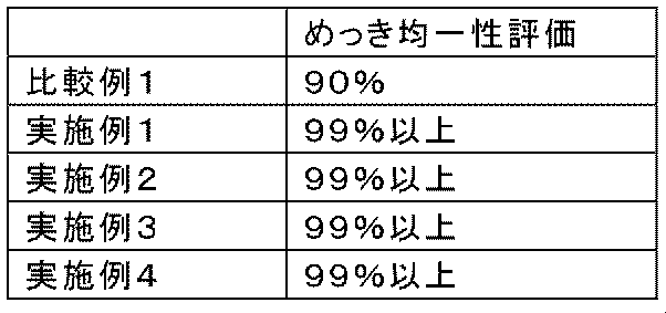
<考察>
本発明の実施例に係るめっき装置を使用することにより、各エレメントに対して高い均一性でめっき被膜を形成可能であった。また、給電用鉄球は陽極と離れており、かつ樹脂容器で囲まれているので鉄球にはほとんどめっきが付かなかった。 <Discussion>
By using the plating apparatus according to the example of the present invention, it was possible to form a plating film with high uniformity on each element. Moreover, since the power supply iron ball was separated from the anode and surrounded by the resin container, the iron ball was hardly plated.
(実施例5.陰極からの距離とめっき最大距離の関係)
図2~図4に示す構造の絶縁性容器を以下の仕様で作製した。陰極は、ファスナーチェーンの通過方向の先頭側の内側面のみに設けた。
・導電性媒体:3μm程度の厚みのピロリン酸銅めっき被膜を表面に有する鉄球、直径4.5mm、450個、積層数=6個
・絶縁性容器:アクリル樹脂製
・絶縁性容器のファスナーチェーン搬送方向の長さ:20cm
・傾斜角度:9°
・開口116:開口率54%、直径2mmの円形状の穴、千鳥状に配列
・隙間C1、C2:2mm
・幅W2:10mm (Example 5. Relationship between distance from cathode and maximum plating distance)
An insulating container having the structure shown in FIGS. 2 to 4 was produced with the following specifications. The cathode was provided only on the inner surface on the leading side in the passing direction of the fastener chain.
-Conductive medium: Iron ball having a copper pyrophosphate plating film with a thickness of about 3 μm on the surface, diameter 4.5 mm, 450 pieces, number of layers = 6-Insulating container: made of acrylic resin-Fastener chain of insulating container Length in transport direction: 20cm
・ Inclination angle: 9 °
Opening 116: Opening ratio 54%, circular holes with a diameter of 2 mm, staggered arrangement Clearances C1, C2: 2 mm
, Width W 2: 10mm
めっき試験条件は以下である。
・ファスナーチェーンの仕様:YKK(株)製型式5RGチェーン(チェーン幅:5.75mm、エレメント素材:丹銅)
・めっき液:120L、組成:ニッケルめっき用めっき液
・ファスナーチェーンの搬送を停止し、絶縁性容器内のファスナーチェーンを左右に揺動しながら、陰極に2Aの電流を10秒間流した。 The plating test conditions are as follows.
-Fastener chain specifications: YKK model 5RG chain (chain width: 5.75 mm, element material: red)
-Plating solution: 120 L, composition: plating solution for nickel plating-Fastener chain transportation was stopped, and a current of 2 A was applied to the cathode for 10 seconds while the fastener chain in the insulating container was swung left and right.
めっき試験後、目視によりめっきの付着が確認されたエレメントのうち、陰極から最も遠いエレメントまでの距離を測定したところ、12cmであった。次いで、陰極における電流値及びめっき時間を、表2に記載の条件に変化させた他は同一の試験条件として、目視によりめっきの付着が確認されたエレメントのうち、陰極から最も遠いエレメントまでの距離をそれぞれ測定した。結果を表2に示す。
After the plating test, the distance from the cathode to the furthest element among the elements that were visually confirmed to be adhered was 12 cm. Next, as the same test conditions except that the current value and plating time at the cathode were changed to the conditions shown in Table 2, the distance from the cathode to the furthest element among the elements that were visually confirmed to adhere to the plating Was measured respectively. The results are shown in Table 2.
また、D0=2A、I0=12cmを基準にして、以下の実験式に基づき、陰極における電流(I1)を1.5A、1.0A、0.5Aと変化させたときの、エレメントがめっきされる最大距離(D1)を求めた。結果を表2に示す。実験結果は実験式から求めた最大距離によく一致していることが分かる。
The element when the current (I 1 ) at the cathode is changed to 1.5 A, 1.0 A, and 0.5 A based on the following empirical formula based on D 0 = 2A and I 0 = 12 cm. The maximum distance (D 1 ) at which is plated. The results are shown in Table 2. It can be seen that the experimental results agree well with the maximum distance obtained from the experimental formula.
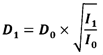

(実施例6.陰極を複数設置することによるめっき効率の向上)
ファスナーチェーンの通過方向の先頭側の内側面(地点A)、ファスナーチェーンの通過方向に平行な内側面であって、ファスナーチェーンの通過方向の先頭側の内側面から7cm離れた箇所(地点B)及び14cm離れた箇所(地点C)の計3か所に陰極を設けた他は、実施例5と同一の絶縁性容器を作製した。 (Example 6. Improvement of plating efficiency by installing a plurality of cathodes)
Inner side surface on the leading side in the passing direction of the fastener chain (point A), an inner side surface parallel to the passing direction of the fastener chain, and 7 cm away from the inner side surface on the leading side in the passing direction of the fastener chain (point B) And the insulating container same as Example 5 was produced except having provided the cathode in a total of three places of 14 cm away (point C).
めっき試験条件は以下である。
・ファスナーチェーンの仕様:YKK(株)製型式5RGチェーン(チェーン幅:5.75mm、エレメント素材:丹銅)
・めっき液:120L、組成:ニッケルめっき用めっき液
・ファスナーチェーンの搬送を停止し、絶縁性容器内のファスナーチェーンを左右に揺動しながら、各陰極の電流値を表3に示す値に設定して表3に記載の時間めっきした。 The plating test conditions are as follows.
-Fastener chain specifications: YKK model 5RG chain (chain width: 5.75 mm, element material: red)
・ Plating solution: 120L, composition: plating solution for nickel plating ・ Conveyance of fastener chain is stopped, and the current value of each cathode is set to the values shown in Table 3 while the fastener chain in the insulating container is swung left and right. Then, plating was performed for the time shown in Table 3.
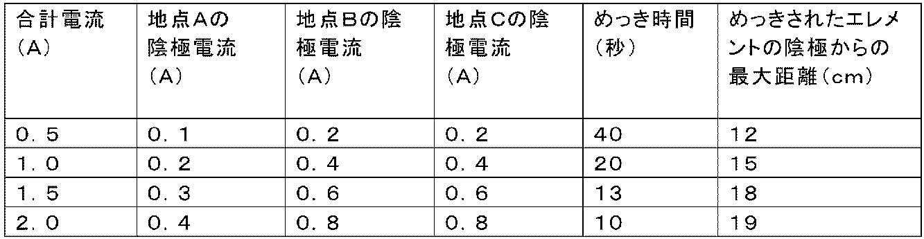
実施例5との対比から、陰極を複数設置することで、各陰極への電流値を抑制しながらも、めっき可能なエレメントの領域が増加することが理解できる。また、合計電流値が同じでも各陰極における最大電流値は半分以下になることから、陰極を一か所に設置する場合と比較して、2倍以上の合計電流値でめっき可能であることが理解できる。このことは、ファスナーチェーンの走行速度を2倍以上にしてもめっき可能であることを示唆している。
From the comparison with Example 5, it can be understood that the installation of a plurality of cathodes increases the area of elements that can be plated while suppressing the current value to each cathode. In addition, even if the total current value is the same, the maximum current value in each cathode is less than half, so that it is possible to plate with a total current value more than twice as compared with the case where the cathode is installed in one place. Understandable. This suggests that plating is possible even when the travel speed of the fastener chain is doubled or more.
1 ファスナーテープ
2 芯部
3 エレメント
4 上止具
5 下止具
6 スライダー
7 ファスナーチェーン
110 絶縁性容器
110a 第一の絶縁性容器
110b 第二の絶縁性容器
111 導電性媒体
112 通路
112a ファスナーチェーンの一方の主表面側と対向する側の路面
112b ファスナーチェーンの他方の主表面側と対向する側の路面
113 収容部
113a 収容部の搬送方向の先頭側の内側面
113b 収容部の搬送方向と平行な内側面
113c 収容部の搬送方向の後尾側の内側面
114 通路への入口
115 通路からの出口
116 開口
117 開口
118 陰極
119 陽極
120 ガイド溝
121 仕切り板
201 めっき槽
202 めっき液
203 貯留槽
204、206 めっき槽入口
205、207 めっき槽出口
208 循環ポンプ
209 ヒータ
210、214、216 戻りパイプ
212 送りパイプ
310a 第一の回転バレル(第一の絶縁性容器)
310b 第二の回転バレル(第二の絶縁性容器)
311 導電性媒体
312 ガイド部材
313 回転軸
314a 第一の回転バレルの入口
315a 第一の回転バレルの出口
314b 第二の回転バレルの入口
315b 第二の回転バレルの出口
316 陽極
317 陰極
318 開口
321 仕切り板
401 めっき槽
402 めっき液
403 貯留槽
406 めっき槽入口
407 めっき槽出口
408 循環ポンプ
409 ヒータ
410 戻りパイプ
412 送りパイプ DESCRIPTION OFSYMBOLS 1 Fastener tape 2 Core part 3 Element 4 Upper stopper 5 Lower stopper 6 Slider 7 Fastener chain 110 Insulating container 110a First insulating container 110b Second insulating container 111 Conductive medium 112 Passage 112a One of the fastener chains Road surface 112b facing the main surface side of the zipper Chain Road surface 113 facing the other main surface side of the fastener chain 113 Housing portion 113a Inner side surface 113b of the housing portion in the transport direction Inner side parallel to the transport direction of the housing portion Side surface 113c Inner side surface 114 on the tail side in the conveying direction of the accommodating portion Inlet 115 to the passage 115 Outlet 116 from the passage 116 Opening 117 Opening 118 Cathode 119 Anode 120 Guide groove 121 Partition plate 201 Plating tank 202 Plating solution 203 Reserving tank 204, 206 Plating Tank inlet 205, 207 Plating tank outlet 208 Ring pump 209 heater 210, 214, 216 return pipe 212 feed pipe 310a first rotating barrel (first insulating container)
310b Second rotating barrel (second insulating container)
311 Conductive medium 312Guide member 313 Rotating shaft 314a First rotating barrel inlet 315a First rotating barrel outlet 314b Second rotating barrel inlet 315b Second rotating barrel outlet 316 Anode 317 Cathode 318 Opening 321 Partition Plate 401 Plating tank 402 Plating solution 403 Storage tank 406 Plating tank inlet 407 Plating tank outlet 408 Circulation pump 409 Heater 410 Return pipe 412 Feed pipe
2 芯部
3 エレメント
4 上止具
5 下止具
6 スライダー
7 ファスナーチェーン
110 絶縁性容器
110a 第一の絶縁性容器
110b 第二の絶縁性容器
111 導電性媒体
112 通路
112a ファスナーチェーンの一方の主表面側と対向する側の路面
112b ファスナーチェーンの他方の主表面側と対向する側の路面
113 収容部
113a 収容部の搬送方向の先頭側の内側面
113b 収容部の搬送方向と平行な内側面
113c 収容部の搬送方向の後尾側の内側面
114 通路への入口
115 通路からの出口
116 開口
117 開口
118 陰極
119 陽極
120 ガイド溝
121 仕切り板
201 めっき槽
202 めっき液
203 貯留槽
204、206 めっき槽入口
205、207 めっき槽出口
208 循環ポンプ
209 ヒータ
210、214、216 戻りパイプ
212 送りパイプ
310a 第一の回転バレル(第一の絶縁性容器)
310b 第二の回転バレル(第二の絶縁性容器)
311 導電性媒体
312 ガイド部材
313 回転軸
314a 第一の回転バレルの入口
315a 第一の回転バレルの出口
314b 第二の回転バレルの入口
315b 第二の回転バレルの出口
316 陽極
317 陰極
318 開口
321 仕切り板
401 めっき槽
402 めっき液
403 貯留槽
406 めっき槽入口
407 めっき槽出口
408 循環ポンプ
409 ヒータ
410 戻りパイプ
412 送りパイプ DESCRIPTION OF
310b Second rotating barrel (second insulating container)
311 Conductive medium 312
Claims (31)
- 金属製エレメントの列を有するファスナーチェーンの電気めっき方法であって、
各金属製エレメントがめっき槽中のめっき液に接触した状態で、陰極(118、317)に電気的に接触した複数の導電性媒体(111、311)が流動可能に収容された一つ又は二つ以上の第一の絶縁性容器(110a、310a)内を該ファスナーチェーンが通過する工程を含み、
該ファスナーチェーンが第一の絶縁性容器(110a、310a)内を通過中に主として該ファスナーチェーンの第一の主表面側に露出した各金属製エレメントの表面を第一の絶縁性容器(110a、310a)内の前記複数の導電性媒体(111、311)に接触させることにより給電し、
第一の陽極(119、316)を該ファスナーチェーンの第二の主表面側に露出した各金属製エレメントの表面と対向する位置関係で設置する、
電気めっき方法。 A method of electroplating fastener chains having rows of metal elements,
One or two of the plurality of conductive media (111, 311) that are in electrical contact with the cathodes (118, 317) are flowably accommodated in a state where each metal element is in contact with the plating solution in the plating tank. Passing the fastener chain through one or more first insulating containers (110a, 310a);
While the fastener chain passes through the first insulating container (110a, 310a), the surface of each metal element exposed mainly on the first main surface side of the fastener chain is the first insulating container (110a, A power supply by contacting the plurality of conductive media (111, 311) in 310a);
Installing the first anode (119, 316) in a positional relationship facing the surface of each metal element exposed on the second main surface side of the fastener chain;
Electroplating method. - 前記ファスナーチェーンが第一の絶縁性容器(110a、310a)内を上昇しながら通過する請求項1に記載の電気めっき方法。 The electroplating method according to claim 1, wherein the fastener chain passes while rising in the first insulating container (110a, 310a).
- 前記ファスナーチェーンが第一の絶縁性容器(110a、310a)内を鉛直方向に上昇しながら通過する請求項2に記載の電気めっき方法。 The electroplating method according to claim 2, wherein the fastener chain passes through the first insulating container (110a, 310a) while rising in the vertical direction.
- 該ファスナーチェーンが第一の絶縁性容器(110a)内を通過中に、該ファスナーチェーンの第一の主表面側に露出した各金属製エレメントの表面のみを第一の絶縁性容器(110a)内の前記複数の導電性媒体(111)に接触させることにより給電する請求項1~3のいずれか一項に記載の電気めっき方法。 While the fastener chain is passing through the first insulating container (110a), only the surface of each metal element exposed on the first main surface side of the fastener chain is inside the first insulating container (110a). The electroplating method according to any one of claims 1 to 3, wherein power is supplied by contacting the plurality of conductive media (111).
- 各金属製エレメントがめっき槽中のめっき液に接触した状態で、陰極(118、317)に電気的に接触した複数の導電性媒体(111、311)が流動可能に収容された一つ又は二つ以上の第二の絶縁性容器(110b、310b)内を該ファスナーチェーンが通過する工程を更に含み、
該ファスナーチェーンが第二の絶縁性容器(110b、310b)内を通過中に、主として該ファスナーチェーンの第二の主表面側に露出した各金属製エレメントの表面を第二の絶縁性容器(110b、310b)内の前記複数の導電性媒体(111、311)に接触させることにより給電し、
第二の陽極(119、316)を該ファスナーチェーンの第一の主表面側に露出した各金属製エレメントの表面と対向する位置関係で設置する、
請求項1~4の何れか一項に記載の電気めっき方法。 One or two of the plurality of conductive media (111, 311) that are in electrical contact with the cathodes (118, 317) are flowably accommodated in a state where each metal element is in contact with the plating solution in the plating tank. Further comprising the step of passing the fastener chain through one or more second insulating containers (110b, 310b);
While the fastener chain is passing through the second insulating container (110b, 310b), the surface of each metal element exposed mainly on the second main surface side of the fastener chain is mainly covered with the second insulating container (110b). , 310b) to contact the plurality of conductive media (111, 311) to supply power,
Installing the second anode (119, 316) in a positional relationship facing the surface of each metal element exposed on the first main surface side of the fastener chain;
The electroplating method according to any one of claims 1 to 4. - 該ファスナーチェーンが第二の絶縁性容器(110b)内を通過中に、該ファスナーチェーンの第二の主表面側に露出した各金属製エレメントの表面のみを第二の絶縁性容器(110b)内の前記複数の導電性媒体(111)に接触することにより給電する請求項5に記載の電気めっき方法。 While the fastener chain passes through the second insulating container (110b), only the surface of each metal element exposed on the second main surface side of the fastener chain is placed in the second insulating container (110b). The electroplating method according to claim 5, wherein power is supplied by contacting the plurality of conductive media (111).
- 導電性媒体(111、311)が球状である請求項1~6のいずれか一項に記載の電気めっき方法。 The electroplating method according to any one of claims 1 to 6, wherein the conductive medium (111, 311) is spherical.
- 第一の絶縁性容器(110a)は、前記ファスナーチェーンの走行経路を案内する通路(112)、及び複数の導電性媒体(111)を流動可能に収容する収容部(113)を内部に有し、
該通路(112)は前記ファスナーチェーンの入口(114)と、前記ファスナーチェーンの出口(115)と、前記ファスナーチェーンの第一の主表面側と対向する側の路面(112a)に前記複数の導電性媒体(111)へのアクセスを可能とする一つ又は二つ以上の開口(117)と、前記ファスナーチェーンの第二の主表面側と対向する側の路面(112b)にめっき液が連通可能な一つ又は二つ以上の開口(116)とを有し、
前記複数の導電性媒体(111)へのアクセスを可能とする一つ又は二つ以上の開口(117)について、チェーン幅方向の長さをW2とし、導電性媒体(111)の直径をDとすると、2D<W2<6Dの関係が成立する請求項7に記載の電気めっき方法。 The first insulating container (110a) has therein a passage (112) for guiding the travel path of the fastener chain, and an accommodating portion (113) for accommodating a plurality of conductive media (111) in a flowable manner. ,
The passage (112) has a plurality of conductive layers on the inlet (114) of the fastener chain, the outlet (115) of the fastener chain, and a road surface (112a) on the side facing the first main surface side of the fastener chain. The plating solution can communicate with one or two or more openings (117) that allow access to the conductive medium (111) and the road surface (112b) that faces the second main surface side of the fastener chain. One or more openings (116),
For one or two or more openings (117) that allow access to the plurality of conductive media (111), the length in the chain width direction is W 2 and the diameter of the conductive media (111) is D. Then, the electroplating method according to claim 7, wherein a relationship of 2D <W 2 <6D is established. - 第一の絶縁性容器(110a、310a)に用いられる前記陰極(118、317)は、第一の絶縁性容器(110a、310a)の内側面に複数箇所設置される請求項1~8の何れか一項に記載の電気めっき方法。 The cathode (118, 317) used in the first insulating container (110a, 310a) is installed at a plurality of locations on the inner surface of the first insulating container (110a, 310a). The electroplating method according to claim 1.
- 前記陰極(118、317)は、第一の絶縁性容器(110a、310a)の内側面のうち、ファスナーチェーンの通過方向の先頭側の内側面(113a)と、ファスナーチェーンの通過方向に平行な内側面(113b)の後尾部とに少なくとも一箇所ずつ設置される請求項9に記載の電気めっき方法。 The cathodes (118, 317) are parallel to the inner side surface (113a) of the leading side in the passing direction of the fastener chain and the passing direction of the fastener chain among the inner side surfaces of the first insulating containers (110a, 310a). The electroplating method according to claim 9, wherein the electroplating method is installed at least one place on the rear side of the inner side surface (113 b).
- 前記陰極(118、317)は、第一の絶縁性容器(110a、310a)の内側面のうち、ファスナーチェーンの通過方向に平行な内側面(113b)の、ファスナーチェーンの通過方向中央部に少なくとも一箇所設置される請求項10に記載の電気めっき方法。 The cathode (118, 317) is at least at the center of the inner side surface (113b) of the first insulating container (110a, 310a) parallel to the passing direction of the fastener chain in the passing direction of the fastener chain. The electroplating method according to claim 10 installed at one place.
- 第一の絶縁性容器(110a、310a)の内側面のうち、ファスナーチェーンの通過方向に平行な内側面(113b)に設置される前記陰極(118、317)は、当該内側面と面一に設置される請求項11に記載の電気めっき方法。 Of the inner surfaces of the first insulating containers (110a, 310a), the cathodes (118, 317) installed on the inner surface (113b) parallel to the passing direction of the fastener chain are flush with the inner surfaces. The electroplating method of Claim 11 installed.
- 第一の絶縁性容器(110a、310a)の内側面のうち、ファスナーチェーンの通過方向に平行な内側面(113b)に設置される前記陰極(118、317)は、当該内側面のファスナーチェーンの通過方向の長さ100%に対して、ファスナーチェーンの通過方向の先頭側から30~70%の範囲内に設置される請求項11又は12に記載の電気めっき方法。 Of the inner side surfaces of the first insulating containers (110a, 310a), the cathodes (118, 317) installed on the inner side surface (113b) parallel to the passing direction of the fastener chain are connected to the fastener chain on the inner side surface. The electroplating method according to claim 11 or 12, wherein the electroplating method is installed within a range of 30 to 70% from a leading side in the passing direction of the fastener chain with respect to a length of 100% in the passing direction.
- 前記陰極(118、317)は、ファスナーチェーンの通過方向に等間隔に複数設置される請求項9~13の何れか一項に記載の電気めっき方法。 The electroplating method according to any one of claims 9 to 13, wherein a plurality of the cathodes (118, 317) are installed at equal intervals in a passing direction of the fastener chain.
- 複数設置される前記陰極(118、317)の電位は同一である請求項9~14の何れか一項に記載の電気めっき方法。 The electroplating method according to any one of claims 9 to 14, wherein a plurality of the cathodes (118, 317) provided have the same potential.
- 第一の絶縁性容器(110a、310a)内を通過中のエレメントのうち、電流密度の最も高いエレメントにおける電流密度をDmax、第一の絶縁性容器(110a、310a)内を通過中のエレメントのうち、電流密度の最も低いエレメントにおける電流密度をDminとすると、0.8≦Dmin/Dmaxが成立する請求項9~15の何れか一項に記載の電気めっき方法。 Among the elements passing through the first insulating container (110a, 310a), the current density of the element having the highest current density is D max , and the element passing through the first insulating container (110a, 310a) 16. The electroplating method according to claim 9, wherein 0.8 ≦ D min / D max is established, where D min is a current density in an element having the lowest current density.
- 第二の絶縁性容器(110b、310b)に用いられる前記陰極(118、317)は、第二の絶縁性容器(110b、310b)の内側面に複数箇所設置される請求項5又は6に従属する請求項9~16の何れか一項に記載の電気めっき方法。 The said cathode (118,317) used for a 2nd insulating container (110b, 310b) is dependent on Claim 5 or 6 installed in multiple places on the inner surface of a 2nd insulating container (110b, 310b). The electroplating method according to any one of claims 9 to 16.
- 金属製エレメントの列を有するファスナーチェーンの電気めっき装置であって、
めっき液を収容可能なめっき槽(201、401)と、
めっき槽(201、401)中に配置された第一の陽極(119、316)と、
めっき槽(201、401)中に配置され、且つ、複数の導電性媒体(111、311)が陰極(118、317)に電気的に接触した状態で流動可能に収容された一つ又は二つ以上の第一の絶縁性容器(110a、310a)と、
を備え、
第一の絶縁性容器(110a、310a)は、主として該ファスナーチェーンの第一の主表面側に露出した各金属製エレメントの表面を第一の絶縁性容器(110a、310a)内の前記複数の導電性媒体(111、311)に接触させながら、該ファスナーチェーンが第一の絶縁性容器(110a、310a)内を通過することが可能なように構成されており、
第一の陽極(119、316)は、該ファスナーチェーンが第一の絶縁性容器(110a、310a)を通過する際に、該ファスナーチェーンの第二の主表面側に露出した各金属製エレメントの表面と対向する位置関係で設置されている、
電気めっき装置。 An electroplating device for a fastener chain having a row of metal elements,
A plating tank (201, 401) capable of containing a plating solution;
A first anode (119, 316) disposed in the plating tank (201, 401);
One or two arranged in the plating tank (201, 401) and accommodated in a state where a plurality of conductive media (111, 311) are in electrical contact with the cathode (118, 317). The above first insulating container (110a, 310a),
With
The first insulating container (110a, 310a) is formed by mainly exposing the surface of each metal element exposed on the first main surface side of the fastener chain in the first insulating container (110a, 310a). The fastener chain is configured to be able to pass through the first insulating container (110a, 310a) while being in contact with the conductive medium (111, 311).
The first anode (119, 316) is formed of each metal element exposed to the second main surface side of the fastener chain when the fastener chain passes through the first insulating container (110a, 310a). Installed in a positional relationship facing the surface,
Electroplating equipment. - 第一の絶縁性容器(110a)は、前記ファスナーチェーンの走行経路を案内する通路(112)、及び複数の導電性媒体(111)を流動可能に収容する収容部(113)を内部に有し、
該通路(112)は前記ファスナーチェーンの入口(114)と、前記ファスナーチェーンの出口(115)と、前記ファスナーチェーンの第一の主表面側と対向する側の路面(112a)に前記複数の導電性媒体(111)へのアクセスを可能とする一つ又は二つ以上の開口(117)と、前記ファスナーチェーンの第二の主表面側と対向する側の路面(112b)にめっき液が連通可能な一つ又は二つ以上の開口(116)とを有する、
請求項18に記載の電気めっき装置。 The first insulating container (110a) has therein a passage (112) for guiding the travel path of the fastener chain, and an accommodating portion (113) for accommodating a plurality of conductive media (111) in a flowable manner. ,
The passage (112) has a plurality of conductive layers on the inlet (114) of the fastener chain, the outlet (115) of the fastener chain, and a road surface (112a) on the side facing the first main surface side of the fastener chain. The plating solution can communicate with one or two or more openings (117) that allow access to the conductive medium (111) and the road surface (112b) that faces the second main surface side of the fastener chain. One or more openings (116).
The electroplating apparatus according to claim 18. - 前記通路(112)は入口(114)の上方に出口(115)を有する請求項18又は19に記載の電気めっき装置。 The electroplating apparatus according to claim 18 or 19, wherein the passage (112) has an outlet (115) above the inlet (114).
- 前記通路(112)は入口(114)の鉛直上方に出口(115)を有する請求項20に記載の電気めっき装置。 21. The electroplating apparatus according to claim 20, wherein the passage (112) has an outlet (115) vertically above the inlet (114).
- めっき槽(201、401)中に配置された第二の陽極(119、316)と、
めっき槽(201、401)中に配置され、且つ、複数の導電性媒体(111、311)が陰極(118、317)に電気的に接触した状態で流動可能に収容された一つ又は二つ以上の第二の絶縁性容器(110b、310b)と、
を更に備え、
第二の絶縁性容器(110b、310b)は、主として該ファスナーチェーンの第二の主表面側に露出した各金属製エレメントの表面を第二の絶縁性容器(110b、310b)内の前記複数の導電性媒体(111、311)に接触させながら、該ファスナーチェーンが第二の絶縁性容器(110b、310b)内を通過することが可能なように構成されており、
第二の陽極(119、316)は、該ファスナーチェーンが第二の絶縁性容器(110b、310b)を通過する際に、該ファスナーチェーンの第一の主表面側に露出した各金属製エレメントの表面と対向する位置関係で設置されている、
請求項18~21のいずれか一項に記載の電気めっき装置。 A second anode (119, 316) disposed in the plating tank (201, 401);
One or two arranged in the plating tank (201, 401) and accommodated in a state where a plurality of conductive media (111, 311) are in electrical contact with the cathode (118, 317). The second insulating container (110b, 310b),
Further comprising
The second insulating container (110b, 310b) mainly has the surface of each metal element exposed on the second main surface side of the fastener chain in the second insulating container (110b, 310b). The fastener chain is configured to be able to pass through the second insulating container (110b, 310b) while being in contact with the conductive medium (111, 311).
The second anode (119, 316) is formed of each metal element exposed to the first main surface side of the fastener chain when the fastener chain passes through the second insulating container (110b, 310b). Installed in a positional relationship facing the surface,
The electroplating apparatus according to any one of claims 18 to 21. - 第一の絶縁性容器(310a)は、該ファスナーチェーンが第一の主表面を下側に、第二の主表面を上側にして第一の絶縁性容器(310a)内を通過することが可能なように構成されており、
第一の絶縁性容器(310a)は、前記ファスナーチェーンの入口(314a)と、前記ファスナーチェーンの出口(315a)と、前記ファスナーチェーンの走行方向に平行な回転軸(313)とを有する回転バレルであり、
前記複数の導電性媒体(311)は該回転バレル内で、前記ファスナーチェーンの第二の主表面側に露出した各金属製エレメントの表面よりも、前記ファスナーチェーンの第一の主表面側に露出した各金属製エレメントの表面へ優先的に接触する高さまで充填されている、
請求項18に記載の電気めっき装置。 The first insulating container (310a) allows the fastener chain to pass through the first insulating container (310a) with the first main surface facing down and the second main surface facing up. It is configured so that
The first insulating container (310a) has a rotating barrel having an inlet (314a) of the fastener chain, an outlet (315a) of the fastener chain, and a rotating shaft (313) parallel to the traveling direction of the fastener chain. And
The plurality of conductive media (311) are exposed to the first main surface side of the fastener chain in the rotating barrel from the surface of each metal element exposed to the second main surface side of the fastener chain. Filled to a height that preferentially contacts the surface of each metal element
The electroplating apparatus according to claim 18. - 第二の絶縁性容器(310b)は、該ファスナーチェーンが第一の主表面を下側に、第二の主表面を上側にして第二の絶縁性容器(310b)内を通過することが可能なように構成されており、
第二の絶縁性容器(310b)は、前記ファスナーチェーンの入口(314b)と、前記ファスナーチェーンの出口(315b)と、前記ファスナーチェーンの走行方向に平行な回転軸(313)とを有する回転バレルであり、
該回転バレル内に収容された前記複数の導電性媒体(311)が、前記ファスナーチェーンの第一の主表面側に露出した各金属製エレメントの表面よりも、前記ファスナーチェーンの第二の主表面側に露出した各金属製エレメントの表面へ優先的に接触するように、該回転バレルは回転軸(313)に平行な内側面から内側に向かって突出した少なくとも一つのガイド部材(312)を有する、
請求項22に記載の電気めっき装置。 The second insulating container (310b) allows the fastener chain to pass through the second insulating container (310b) with the first main surface facing down and the second main surface facing up. It is configured so that
The second insulating container (310b) has a rotating barrel having an inlet (314b) of the fastener chain, an outlet (315b) of the fastener chain, and a rotating shaft (313) parallel to the traveling direction of the fastener chain. And
The plurality of conductive media (311) accommodated in the rotating barrel is more in the second main surface of the fastener chain than the surface of each metal element exposed on the first main surface side of the fastener chain. The rotating barrel has at least one guide member (312) projecting inward from an inner surface parallel to the rotation axis (313) so as to preferentially contact the surface of each metal element exposed to the side. ,
The electroplating apparatus according to claim 22. - 第一の絶縁性容器(110a、310a)に用いられる前記陰極(118、317)は、第一の絶縁性容器(110a、310a)の内側面に複数箇所設置される請求項18~24の何れか一項に記載の電気めっき装置。 The cathode (118, 317) used in the first insulating container (110a, 310a) is installed at a plurality of locations on the inner surface of the first insulating container (110a, 310a). The electroplating apparatus according to claim 1.
- 前記陰極(118、317)は、第一の絶縁性容器(110a、310a)の内側面のうち、ファスナーチェーンの通過方向の先頭側の内側面(113a)と、ファスナーチェーンの通過方向に平行な内側面(113b)の後尾部とに少なくとも一箇所ずつ設置される請求項25に記載の電気めっき装置。 The cathodes (118, 317) are parallel to the inner side surface (113a) of the leading side in the passing direction of the fastener chain and the passing direction of the fastener chain among the inner side surfaces of the first insulating containers (110a, 310a). 26. The electroplating apparatus according to claim 25, wherein the electroplating apparatus is installed at least one place on a rear portion of the inner side surface (113b).
- 前記陰極(118、317)は、第一の絶縁性容器(110a、310a)の内側面のうち、ファスナーチェーンの通過方向に平行な内側面(113b)の、ファスナーチェーンの通過方向中央部に少なくとも一箇所設置される請求項26に記載の電気めっき装置。 The cathode (118, 317) is at least at the center of the inner side surface (113b) of the first insulating container (110a, 310a) parallel to the passing direction of the fastener chain in the passing direction of the fastener chain. 27. The electroplating apparatus according to claim 26 installed at one place.
- 第一の絶縁性容器(110a、310a)の内側面のうち、ファスナーチェーンの通過方向に平行な内側面(113b)に設置される前記陰極(118、317)は、当該内側面と面一に設置される請求項27に記載の電気めっき装置。 Of the inner surfaces of the first insulating containers (110a, 310a), the cathodes (118, 317) installed on the inner surface (113b) parallel to the passing direction of the fastener chain are flush with the inner surfaces. The electroplating apparatus according to claim 27, which is installed.
- 第一の絶縁性容器(110a、310a)の内側面のうち、ファスナーチェーンの通過方向に平行な内側面(113b)に設置される前記陰極(118、317)は、当該内側面のファスナーチェーンの通過方向の長さ100%に対して、ファスナーチェーンの通過方向の先頭側から30~70%の範囲内に設置される請求項27又は28に記載の電気めっき装置。 Of the inner side surfaces of the first insulating containers (110a, 310a), the cathodes (118, 317) installed on the inner side surface (113b) parallel to the passing direction of the fastener chain are connected to the fastener chain on the inner side surface. The electroplating apparatus according to claim 27 or 28, wherein the electroplating apparatus is installed within a range of 30 to 70% from a leading side in the passing direction of the fastener chain with respect to a length of 100% in the passing direction.
- 前記陰極(118、317)は、ファスナーチェーンの通過方向に等間隔に複数設置される請求項25~29の何れか一項に記載の電気めっき装置。 The electroplating apparatus according to any one of claims 25 to 29, wherein a plurality of the cathodes (118, 317) are installed at equal intervals in a passing direction of the fastener chain.
- 第二の絶縁性容器(110b、310b)に用いられる前記陰極(118、317)は、第二の絶縁性容器(110b、310b)の内側面に複数箇所設置される請求項22に従属する請求項25~30の何れか一項に記載の電気めっき装置。 Claim according to claim 22, wherein the cathodes (118, 317) used in the second insulating container (110b, 310b) are disposed at a plurality of positions on the inner surface of the second insulating container (110b, 310b). Item 30. The electroplating apparatus according to any one of Items 25 to 30.
Priority Applications (4)
| Application Number | Priority Date | Filing Date | Title |
|---|---|---|---|
| CN201780076599.9A CN110062822B (en) | 2016-12-13 | 2017-09-06 | Electroplating method for metal zipper and electroplating device for metal zipper |
| EP17879846.8A EP3556907B1 (en) | 2016-12-13 | 2017-09-06 | Electroplating method for metal fastener and electroplating device for metal fastener |
| JP2018556179A JP6670951B2 (en) | 2016-12-13 | 2017-09-06 | Electroplating method for metal fastener and electroplating apparatus for metal fastener |
| TW106143629A TWI639733B (en) | 2016-12-13 | 2017-12-13 | Metal zipper plating method and metal zipper plating device |
Applications Claiming Priority (2)
| Application Number | Priority Date | Filing Date | Title |
|---|---|---|---|
| PCT/JP2016/087127 WO2018109848A1 (en) | 2016-12-13 | 2016-12-13 | Electroplating method for metal fastener and electroplating device for metal fastener |
| JPPCT/JP2016/087127 | 2016-12-13 |
Publications (1)
| Publication Number | Publication Date |
|---|---|
| WO2018109998A1 true WO2018109998A1 (en) | 2018-06-21 |
Family
ID=62558224
Family Applications (4)
| Application Number | Title | Priority Date | Filing Date |
|---|---|---|---|
| PCT/JP2016/087127 WO2018109848A1 (en) | 2016-12-13 | 2016-12-13 | Electroplating method for metal fastener and electroplating device for metal fastener |
| PCT/JP2017/030196 WO2018109983A1 (en) | 2016-12-13 | 2017-08-23 | Method and device for electroplating fastener chain |
| PCT/JP2017/032166 WO2018109998A1 (en) | 2016-12-13 | 2017-09-06 | Electroplating method for metal fastener and electroplating device for metal fastener |
| PCT/JP2017/033993 WO2018110019A1 (en) | 2016-12-13 | 2017-09-20 | Fastener stringer provided with metal element row having plating film, fastener chain, and slide fastener |
Family Applications Before (2)
| Application Number | Title | Priority Date | Filing Date |
|---|---|---|---|
| PCT/JP2016/087127 WO2018109848A1 (en) | 2016-12-13 | 2016-12-13 | Electroplating method for metal fastener and electroplating device for metal fastener |
| PCT/JP2017/030196 WO2018109983A1 (en) | 2016-12-13 | 2017-08-23 | Method and device for electroplating fastener chain |
Family Applications After (1)
| Application Number | Title | Priority Date | Filing Date |
|---|---|---|---|
| PCT/JP2017/033993 WO2018110019A1 (en) | 2016-12-13 | 2017-09-20 | Fastener stringer provided with metal element row having plating film, fastener chain, and slide fastener |
Country Status (6)
| Country | Link |
|---|---|
| US (1) | US10820667B2 (en) |
| EP (3) | EP3556908B1 (en) |
| JP (3) | JP6670950B2 (en) |
| CN (3) | CN110062823B (en) |
| TW (3) | TWI642379B (en) |
| WO (4) | WO2018109848A1 (en) |
Cited By (1)
| Publication number | Priority date | Publication date | Assignee | Title |
|---|---|---|---|---|
| WO2023013054A1 (en) * | 2021-08-06 | 2023-02-09 | Ykk株式会社 | Production method for fastener stringer, fastener chain, and slide fastener, and electroplating apparatus |
Families Citing this family (3)
| Publication number | Priority date | Publication date | Assignee | Title |
|---|---|---|---|---|
| WO2018109848A1 (en) * | 2016-12-13 | 2018-06-21 | Ykk株式会社 | Electroplating method for metal fastener and electroplating device for metal fastener |
| EP4083273A4 (en) * | 2019-12-24 | 2022-11-30 | Ykk Corporation | Electroplating device and method for manufacturing plated product |
| CN112545118A (en) * | 2020-11-11 | 2021-03-26 | 福建亿浦昇户外用品有限公司 | Waterproof zipper with good airtight effect |
Citations (13)
| Publication number | Priority date | Publication date | Assignee | Title |
|---|---|---|---|---|
| JPH059778A (en) * | 1991-07-08 | 1993-01-19 | Matsushita Electric Ind Co Ltd | Plating method and plating electronic parts using the method |
| JPH05239699A (en) | 1992-02-26 | 1993-09-17 | Hitachi Cable Ltd | Plating power feeding device for metal strip |
| JP2514760B2 (en) | 1991-11-05 | 1996-07-10 | ワイケイケイ株式会社 | Slide fastener |
| JPH08209383A (en) | 1995-02-06 | 1996-08-13 | Mitsubishi Paper Mills Ltd | Continuous electroplating of nonwoven web |
| JP3087554B2 (en) | 1993-12-16 | 2000-09-11 | 株式会社村田製作所 | Plating method |
| JP2003041399A (en) * | 2001-03-19 | 2003-02-13 | Tdk Corp | Continuous transport barrel plating equipment |
| JP2003193293A (en) * | 2001-12-28 | 2003-07-09 | Ykk Corp | Method of forming anodically oxidized film for row of zip teeth train of slid fastener chain an apparatus for the same |
| JP2004076092A (en) | 2002-08-16 | 2004-03-11 | Ebara Udylite Kk | Electroplating apparatus and electroplating method |
| JP2004100011A (en) | 2002-09-12 | 2004-04-02 | Murata Mfg Co Ltd | Method for manufacturing electronic component |
| JP2005256131A (en) * | 2004-03-15 | 2005-09-22 | Ykk Corp | Surface treatment device |
| JP2005272875A (en) * | 2004-03-23 | 2005-10-06 | Ykk Corp | Electrolytic treatment method and device |
| JP2008202086A (en) | 2007-02-19 | 2008-09-04 | Murata Mfg Co Ltd | Electrolytic plating method |
| JP5063733B2 (en) | 2009-11-13 | 2012-10-31 | サムソン エレクトロ−メカニックス カンパニーリミテッド. | Barrel plating equipment |
Family Cites Families (35)
| Publication number | Priority date | Publication date | Assignee | Title |
|---|---|---|---|---|
| US2334054A (en) * | 1939-10-27 | 1943-11-09 | Talon Inc | Plating metal fasteners |
| US2517907A (en) | 1945-01-05 | 1950-08-08 | Conmar Prod Corp | Apparatus for electrotreating metal slide fasteners |
| US2715095A (en) * | 1952-10-10 | 1955-08-09 | Charles C Cohn | Method and apparatus for electrolytic treatment of slide fasteners |
| US2991528A (en) * | 1959-03-03 | 1961-07-11 | Irving Constant | Metal slide fasteners and method of making same |
| JPS554072U (en) * | 1978-06-23 | 1980-01-11 | ||
| JPH083158B2 (en) * | 1990-07-09 | 1996-01-17 | ワイケイケイ株式会社 | Power supply drum for surface treatment of the teeth of slide fastener chain |
| JPH059978A (en) * | 1991-07-01 | 1993-01-19 | Shiyouji Toyosato | Beam installation structure of simplified building structure |
| JPH083158A (en) | 1994-04-22 | 1996-01-09 | Sumitomo Chem Co Ltd | Ether compound and its use |
| JP2001008714A (en) | 1999-06-30 | 2001-01-16 | Ykk Corp | Production of adherend with constitution member and adherend with constitution member |
| JP2003180410A (en) * | 2001-12-14 | 2003-07-02 | Ykk Corp | Method of manufacturing slide fastener and attached article with composition members |
| US7208073B1 (en) * | 2002-07-31 | 2007-04-24 | Technic, Inc. | Media for use in plating electronic components |
| CN100389232C (en) * | 2003-12-21 | 2008-05-21 | 福建浔兴拉链科技股份有限公司 | Process for electroplating zipper chain teeth and apparatus therefor |
| JP4225987B2 (en) * | 2005-06-24 | 2009-02-18 | Ykk株式会社 | Warp knitting fastener tape making machine |
| CN100420774C (en) * | 2007-01-31 | 2008-09-24 | 浙江伟星实业发展股份有限公司 | Zinc alloy slide fastener electroplating device |
| CN101608328B (en) * | 2008-06-16 | 2011-07-20 | 福建浔兴拉链科技股份有限公司 | Plating limit device, plating equipment using same and plating method using same |
| TW201137186A (en) * | 2010-04-28 | 2011-11-01 | Thingwell Entpr Co Ltd | Pull-plating apparatus |
| KR101260254B1 (en) * | 2011-04-25 | 2013-05-03 | 박대춘 | A tooth plating apparatus for fastener |
| CN102560582B (en) * | 2011-09-01 | 2015-07-01 | 曾汉琼 | Automatic zipper color plating device and control system thereof |
| CN103386448B (en) * | 2012-05-10 | 2016-01-06 | Ykk株式会社 | The engaged element forming device of slide fastener and the engaged element of slide fastener |
| CN102732923B (en) * | 2012-06-15 | 2016-01-20 | 李甫文 | Chain belt electric plating support, the electroplating device using this support and electro-plating method |
| CN102839405B (en) | 2012-08-21 | 2016-03-02 | 李甫文 | Chain belt electric plates support and uses the electroplating device of this support |
| CN102828213B (en) * | 2012-08-28 | 2016-01-20 | 李甫文 | Chain belt electric plates support and uses the electroplating device of this support |
| CN105188455B (en) * | 2013-03-13 | 2018-04-03 | Ykk株式会社 | The manufacture method of slide fastener long-chain, slide fastener and slide fastener |
| CN105188457B (en) * | 2013-04-09 | 2017-12-01 | Ykk株式会社 | Slide fastener members alloy and slide fastener members |
| CN105755515B (en) * | 2014-04-12 | 2017-07-28 | 陈远婷 | A kind of improved Zinc alloy slide fastener electroplating device |
| CN103911641B (en) * | 2014-04-12 | 2016-05-25 | 陈远婷 | A kind of Zinc alloy slide fastener electroplating device |
| CN105734635B (en) * | 2014-04-12 | 2018-02-27 | 陈远婷 | A kind of Zinc alloy slide fastener electroplating device that can improve coating uniformity |
| CN203855680U (en) * | 2014-04-30 | 2014-10-01 | 曹昌文 | Electroplating device capable of performing continuous rolling electrodeposition on zipper teeth |
| US10238187B2 (en) * | 2014-08-27 | 2019-03-26 | Ykk Corporation | Fastener stringer and slide fastener provided with same |
| WO2016067400A1 (en) * | 2014-10-29 | 2016-05-06 | Ykk株式会社 | Fastener element and fastener element manufacturing method |
| JP6463622B2 (en) * | 2014-11-27 | 2019-02-06 | Ykk株式会社 | Plating equipment, plating unit, and plating line |
| JP6441458B2 (en) * | 2015-03-27 | 2018-12-19 | Ykk株式会社 | Slide fastener element |
| CN104720214A (en) * | 2015-03-31 | 2015-06-24 | 浙江创发拉链科技有限公司 | Surface treatment process for metal zipper |
| CN106011964B (en) * | 2016-07-29 | 2018-03-02 | 重庆鹏雷汽车配件有限公司 | A kind of slide fastener electroplating device |
| WO2018109848A1 (en) * | 2016-12-13 | 2018-06-21 | Ykk株式会社 | Electroplating method for metal fastener and electroplating device for metal fastener |
-
2016
- 2016-12-13 WO PCT/JP2016/087127 patent/WO2018109848A1/en active Application Filing
-
2017
- 2017-08-23 EP EP17880956.2A patent/EP3556908B1/en active Active
- 2017-08-23 WO PCT/JP2017/030196 patent/WO2018109983A1/en unknown
- 2017-08-23 JP JP2018556170A patent/JP6670950B2/en active Active
- 2017-08-23 CN CN201780076622.4A patent/CN110062823B/en active Active
- 2017-09-06 CN CN201780076599.9A patent/CN110062822B/en active Active
- 2017-09-06 WO PCT/JP2017/032166 patent/WO2018109998A1/en unknown
- 2017-09-06 JP JP2018556179A patent/JP6670951B2/en active Active
- 2017-09-06 EP EP17879846.8A patent/EP3556907B1/en active Active
- 2017-09-20 WO PCT/JP2017/033993 patent/WO2018110019A1/en unknown
- 2017-09-20 JP JP2018556192A patent/JP6670952B2/en active Active
- 2017-09-20 CN CN201780076588.0A patent/CN110062821B/en active Active
- 2017-09-20 US US16/467,974 patent/US10820667B2/en active Active
- 2017-09-20 EP EP17881625.2A patent/EP3556909B1/en active Active
- 2017-11-01 TW TW106137711A patent/TWI642379B/en active
- 2017-11-03 TW TW106138064A patent/TWI649464B/en active
- 2017-12-13 TW TW106143629A patent/TWI639733B/en active
Patent Citations (13)
| Publication number | Priority date | Publication date | Assignee | Title |
|---|---|---|---|---|
| JPH059778A (en) * | 1991-07-08 | 1993-01-19 | Matsushita Electric Ind Co Ltd | Plating method and plating electronic parts using the method |
| JP2514760B2 (en) | 1991-11-05 | 1996-07-10 | ワイケイケイ株式会社 | Slide fastener |
| JPH05239699A (en) | 1992-02-26 | 1993-09-17 | Hitachi Cable Ltd | Plating power feeding device for metal strip |
| JP3087554B2 (en) | 1993-12-16 | 2000-09-11 | 株式会社村田製作所 | Plating method |
| JPH08209383A (en) | 1995-02-06 | 1996-08-13 | Mitsubishi Paper Mills Ltd | Continuous electroplating of nonwoven web |
| JP2003041399A (en) * | 2001-03-19 | 2003-02-13 | Tdk Corp | Continuous transport barrel plating equipment |
| JP2003193293A (en) * | 2001-12-28 | 2003-07-09 | Ykk Corp | Method of forming anodically oxidized film for row of zip teeth train of slid fastener chain an apparatus for the same |
| JP2004076092A (en) | 2002-08-16 | 2004-03-11 | Ebara Udylite Kk | Electroplating apparatus and electroplating method |
| JP2004100011A (en) | 2002-09-12 | 2004-04-02 | Murata Mfg Co Ltd | Method for manufacturing electronic component |
| JP2005256131A (en) * | 2004-03-15 | 2005-09-22 | Ykk Corp | Surface treatment device |
| JP2005272875A (en) * | 2004-03-23 | 2005-10-06 | Ykk Corp | Electrolytic treatment method and device |
| JP2008202086A (en) | 2007-02-19 | 2008-09-04 | Murata Mfg Co Ltd | Electrolytic plating method |
| JP5063733B2 (en) | 2009-11-13 | 2012-10-31 | サムソン エレクトロ−メカニックス カンパニーリミテッド. | Barrel plating equipment |
Non-Patent Citations (1)
| Title |
|---|
| See also references of EP3556907A4 |
Cited By (1)
| Publication number | Priority date | Publication date | Assignee | Title |
|---|---|---|---|---|
| WO2023013054A1 (en) * | 2021-08-06 | 2023-02-09 | Ykk株式会社 | Production method for fastener stringer, fastener chain, and slide fastener, and electroplating apparatus |
Also Published As
| Publication number | Publication date |
|---|---|
| CN110062822B (en) | 2021-04-13 |
| CN110062821A (en) | 2019-07-26 |
| JP6670951B2 (en) | 2020-03-25 |
| TW201820991A (en) | 2018-06-16 |
| EP3556909B1 (en) | 2023-04-19 |
| TWI642379B (en) | 2018-12-01 |
| JP6670950B2 (en) | 2020-03-25 |
| TWI639733B (en) | 2018-11-01 |
| EP3556908A4 (en) | 2020-09-02 |
| TW201821653A (en) | 2018-06-16 |
| JPWO2018109998A1 (en) | 2019-06-24 |
| WO2018109848A1 (en) | 2018-06-21 |
| JP6670952B2 (en) | 2020-03-25 |
| EP3556907A4 (en) | 2020-09-02 |
| CN110062823B (en) | 2021-06-01 |
| EP3556908B1 (en) | 2021-07-07 |
| CN110062821B (en) | 2021-03-12 |
| US20200085150A1 (en) | 2020-03-19 |
| CN110062823A (en) | 2019-07-26 |
| EP3556908A1 (en) | 2019-10-23 |
| TW201821650A (en) | 2018-06-16 |
| JPWO2018109983A1 (en) | 2019-07-25 |
| CN110062822A (en) | 2019-07-26 |
| EP3556907A1 (en) | 2019-10-23 |
| EP3556907B1 (en) | 2021-08-18 |
| WO2018109983A1 (en) | 2018-06-21 |
| WO2018110019A1 (en) | 2018-06-21 |
| EP3556909A1 (en) | 2019-10-23 |
| EP3556909A4 (en) | 2020-09-02 |
| TWI649464B (en) | 2019-02-01 |
| JPWO2018110019A1 (en) | 2019-06-24 |
| US10820667B2 (en) | 2020-11-03 |
Similar Documents
| Publication | Publication Date | Title |
|---|---|---|
| WO2018109998A1 (en) | Electroplating method for metal fastener and electroplating device for metal fastener | |
| US11692281B2 (en) | Method and apparatus for continuously applying nanolaminate metal coatings | |
| US10472727B2 (en) | Method and apparatus for continuously applying nanolaminate metal coatings | |
| US8110076B2 (en) | Apparatus and foam electroplating process | |
| US3975242A (en) | Horizontal rectilinear type metal-electroplating method | |
| US4601794A (en) | Method and apparatus for continuous electroplating of alloys | |
| EP0125707B1 (en) | Method and apparatus for unilateral electroplating of a moving metal strip | |
| CN114174560A (en) | Method and device for electrolytically coating electrically conductive strips and/or fabrics by means of impulse technology | |
| KR920000247B1 (en) | Device and process for the electro-deposition of metals | |
| CN102828213B (en) | Chain belt electric plates support and uses the electroplating device of this support | |
| CN114808057A (en) | Electroplating device and electroplating system | |
| CN114808084A (en) | Electroplating device and electroplating system | |
| JPS59211597A (en) | Method and device for producing alloy plated steel sheet |
Legal Events
| Date | Code | Title | Description |
|---|---|---|---|
| 121 | Ep: the epo has been informed by wipo that ep was designated in this application |
Ref document number: 17879846 Country of ref document: EP Kind code of ref document: A1 |
|
| ENP | Entry into the national phase |
Ref document number: 2018556179 Country of ref document: JP Kind code of ref document: A |
|
| NENP | Non-entry into the national phase |
Ref country code: DE |
|
| ENP | Entry into the national phase |
Ref document number: 2017879846 Country of ref document: EP Effective date: 20190715 |