WO2018105601A1 - Thermoelectric conversion unit, power generation system, and thermoelectric conversion method - Google Patents
Thermoelectric conversion unit, power generation system, and thermoelectric conversion method Download PDFInfo
- Publication number
- WO2018105601A1 WO2018105601A1 PCT/JP2017/043618 JP2017043618W WO2018105601A1 WO 2018105601 A1 WO2018105601 A1 WO 2018105601A1 JP 2017043618 W JP2017043618 W JP 2017043618W WO 2018105601 A1 WO2018105601 A1 WO 2018105601A1
- Authority
- WO
- WIPO (PCT)
- Prior art keywords
- thermoelectric conversion
- conversion element
- fluid
- exhaust gas
- sheet
- Prior art date
Links
- 238000006243 chemical reaction Methods 0.000 title claims abstract description 522
- 238000010248 power generation Methods 0.000 title claims description 75
- 238000000034 method Methods 0.000 title claims description 50
- 239000012530 fluid Substances 0.000 claims abstract description 92
- 230000005415 magnetization Effects 0.000 claims description 49
- 239000000463 material Substances 0.000 claims description 37
- 239000000203 mixture Substances 0.000 claims description 32
- 230000002159 abnormal effect Effects 0.000 claims description 27
- 230000005291 magnetic effect Effects 0.000 claims description 24
- 238000009826 distribution Methods 0.000 claims description 12
- 230000008878 coupling Effects 0.000 claims description 9
- 238000010168 coupling process Methods 0.000 claims description 9
- 238000005859 coupling reaction Methods 0.000 claims description 9
- 230000005422 Nernst effect Effects 0.000 claims description 8
- 230000005678 Seebeck effect Effects 0.000 claims description 8
- XLYOFNOQVPJJNP-UHFFFAOYSA-N water Substances O XLYOFNOQVPJJNP-UHFFFAOYSA-N 0.000 claims description 8
- 230000035699 permeability Effects 0.000 claims description 5
- 239000007789 gas Substances 0.000 description 264
- 239000000498 cooling water Substances 0.000 description 64
- 239000010408 film Substances 0.000 description 44
- 238000001816 cooling Methods 0.000 description 21
- 229910052751 metal Inorganic materials 0.000 description 19
- 239000002184 metal Substances 0.000 description 19
- 239000000758 substrate Substances 0.000 description 15
- 238000004804 winding Methods 0.000 description 11
- 230000000694 effects Effects 0.000 description 8
- 239000007788 liquid Substances 0.000 description 8
- 229910045601 alloy Inorganic materials 0.000 description 7
- 239000000956 alloy Substances 0.000 description 7
- 238000004519 manufacturing process Methods 0.000 description 6
- 229910052709 silver Inorganic materials 0.000 description 5
- 229910052782 aluminium Inorganic materials 0.000 description 4
- 229910052802 copper Inorganic materials 0.000 description 4
- 230000005611 electricity Effects 0.000 description 4
- 239000010419 fine particle Substances 0.000 description 4
- 239000011553 magnetic fluid Substances 0.000 description 4
- 229910052719 titanium Inorganic materials 0.000 description 4
- XUIMIQQOPSSXEZ-UHFFFAOYSA-N Silicon Chemical compound [Si] XUIMIQQOPSSXEZ-UHFFFAOYSA-N 0.000 description 3
- 230000007423 decrease Effects 0.000 description 3
- 238000005516 engineering process Methods 0.000 description 3
- SZVJSHCCFOBDDC-UHFFFAOYSA-N iron(II,III) oxide Inorganic materials O=[Fe]O[Fe]O[Fe]=O SZVJSHCCFOBDDC-UHFFFAOYSA-N 0.000 description 3
- 229910052710 silicon Inorganic materials 0.000 description 3
- 239000010703 silicon Substances 0.000 description 3
- 238000004544 sputter deposition Methods 0.000 description 3
- 229910000859 α-Fe Inorganic materials 0.000 description 3
- 229910017061 Fe Co Inorganic materials 0.000 description 2
- 229910001289 Manganese-zinc ferrite Inorganic materials 0.000 description 2
- JIYIUPFAJUGHNL-UHFFFAOYSA-N [O--].[O--].[O--].[O--].[O--].[O--].[O--].[O--].[O--].[O--].[O--].[O--].[O--].[O--].[O--].[O--].[O--].[O--].[O--].[O--].[Mn++].[Mn++].[Mn++].[Fe+3].[Fe+3].[Fe+3].[Fe+3].[Fe+3].[Fe+3].[Fe+3].[Fe+3].[Fe+3].[Fe+3].[Zn++].[Zn++] Chemical compound [O--].[O--].[O--].[O--].[O--].[O--].[O--].[O--].[O--].[O--].[O--].[O--].[O--].[O--].[O--].[O--].[O--].[O--].[O--].[O--].[Mn++].[Mn++].[Mn++].[Fe+3].[Fe+3].[Fe+3].[Fe+3].[Fe+3].[Fe+3].[Fe+3].[Fe+3].[Fe+3].[Fe+3].[Zn++].[Zn++] JIYIUPFAJUGHNL-UHFFFAOYSA-N 0.000 description 2
- 238000010586 diagram Methods 0.000 description 2
- 230000005294 ferromagnetic effect Effects 0.000 description 2
- 238000007747 plating Methods 0.000 description 2
- 229910005335 FePt Inorganic materials 0.000 description 1
- 229910003962 NiZn Inorganic materials 0.000 description 1
- 230000005679 Peltier effect Effects 0.000 description 1
- 229910000577 Silicon-germanium Inorganic materials 0.000 description 1
- LEVVHYCKPQWKOP-UHFFFAOYSA-N [Si].[Ge] Chemical compound [Si].[Ge] LEVVHYCKPQWKOP-UHFFFAOYSA-N 0.000 description 1
- 230000002547 anomalous effect Effects 0.000 description 1
- 229910052797 bismuth Inorganic materials 0.000 description 1
- -1 bismuth tellurium compound Chemical class 0.000 description 1
- 230000036760 body temperature Effects 0.000 description 1
- 229910052804 chromium Inorganic materials 0.000 description 1
- 239000000567 combustion gas Substances 0.000 description 1
- 238000002485 combustion reaction Methods 0.000 description 1
- 239000002826 coolant Substances 0.000 description 1
- PMHQVHHXPFUNSP-UHFFFAOYSA-M copper(1+);methylsulfanylmethane;bromide Chemical compound Br[Cu].CSC PMHQVHHXPFUNSP-UHFFFAOYSA-M 0.000 description 1
- 230000002950 deficient Effects 0.000 description 1
- 238000003795 desorption Methods 0.000 description 1
- 230000007613 environmental effect Effects 0.000 description 1
- 229910052737 gold Inorganic materials 0.000 description 1
- 239000002440 industrial waste Substances 0.000 description 1
- 238000009434 installation Methods 0.000 description 1
- 238000009413 insulation Methods 0.000 description 1
- 239000012212 insulator Substances 0.000 description 1
- 229910052742 iron Inorganic materials 0.000 description 1
- 238000005304 joining Methods 0.000 description 1
- 239000000696 magnetic material Substances 0.000 description 1
- 229910052748 manganese Inorganic materials 0.000 description 1
- 239000011572 manganese Substances 0.000 description 1
- 238000002156 mixing Methods 0.000 description 1
- 229910052759 nickel Inorganic materials 0.000 description 1
- 229910052762 osmium Inorganic materials 0.000 description 1
- 229910052697 platinum Inorganic materials 0.000 description 1
- 229910052707 ruthenium Inorganic materials 0.000 description 1
- 239000000126 substance Substances 0.000 description 1
- 239000010409 thin film Substances 0.000 description 1
- 229910052721 tungsten Inorganic materials 0.000 description 1
Images


Classifications
-
- H—ELECTRICITY
- H10—SEMICONDUCTOR DEVICES; ELECTRIC SOLID-STATE DEVICES NOT OTHERWISE PROVIDED FOR
- H10N—ELECTRIC SOLID-STATE DEVICES NOT OTHERWISE PROVIDED FOR
- H10N10/00—Thermoelectric devices comprising a junction of dissimilar materials, i.e. devices exhibiting Seebeck or Peltier effects
- H10N10/10—Thermoelectric devices comprising a junction of dissimilar materials, i.e. devices exhibiting Seebeck or Peltier effects operating with only the Peltier or Seebeck effects
- H10N10/17—Thermoelectric devices comprising a junction of dissimilar materials, i.e. devices exhibiting Seebeck or Peltier effects operating with only the Peltier or Seebeck effects characterised by the structure or configuration of the cell or thermocouple forming the device
-
- H—ELECTRICITY
- H01—ELECTRIC ELEMENTS
- H01L—SEMICONDUCTOR DEVICES NOT COVERED BY CLASS H10
- H01L29/00—Semiconductor devices adapted for rectifying, amplifying, oscillating or switching, or capacitors or resistors with at least one potential-jump barrier or surface barrier, e.g. PN junction depletion layer or carrier concentration layer; Details of semiconductor bodies or of electrodes thereof ; Multistep manufacturing processes therefor
- H01L29/66—Types of semiconductor device ; Multistep manufacturing processes therefor
- H01L29/82—Types of semiconductor device ; Multistep manufacturing processes therefor controllable by variation of the magnetic field applied to the device
-
- H—ELECTRICITY
- H02—GENERATION; CONVERSION OR DISTRIBUTION OF ELECTRIC POWER
- H02N—ELECTRIC MACHINES NOT OTHERWISE PROVIDED FOR
- H02N11/00—Generators or motors not provided for elsewhere; Alleged perpetua mobilia obtained by electric or magnetic means
-
- H—ELECTRICITY
- H10—SEMICONDUCTOR DEVICES; ELECTRIC SOLID-STATE DEVICES NOT OTHERWISE PROVIDED FOR
- H10N—ELECTRIC SOLID-STATE DEVICES NOT OTHERWISE PROVIDED FOR
- H10N15/00—Thermoelectric devices without a junction of dissimilar materials; Thermomagnetic devices, e.g. using the Nernst-Ettingshausen effect
- H10N15/20—Thermomagnetic devices using thermal change of the magnetic permeability, e.g. working above and below the Curie point
-
- F—MECHANICAL ENGINEERING; LIGHTING; HEATING; WEAPONS; BLASTING
- F01—MACHINES OR ENGINES IN GENERAL; ENGINE PLANTS IN GENERAL; STEAM ENGINES
- F01N—GAS-FLOW SILENCERS OR EXHAUST APPARATUS FOR MACHINES OR ENGINES IN GENERAL; GAS-FLOW SILENCERS OR EXHAUST APPARATUS FOR INTERNAL COMBUSTION ENGINES
- F01N5/00—Exhaust or silencing apparatus combined or associated with devices profiting from exhaust energy
- F01N5/02—Exhaust or silencing apparatus combined or associated with devices profiting from exhaust energy the devices using heat
-
- F—MECHANICAL ENGINEERING; LIGHTING; HEATING; WEAPONS; BLASTING
- F02—COMBUSTION ENGINES; HOT-GAS OR COMBUSTION-PRODUCT ENGINE PLANTS
- F02G—HOT GAS OR COMBUSTION-PRODUCT POSITIVE-DISPLACEMENT ENGINE PLANTS; USE OF WASTE HEAT OF COMBUSTION ENGINES; NOT OTHERWISE PROVIDED FOR
- F02G5/00—Profiting from waste heat of combustion engines, not otherwise provided for
- F02G5/02—Profiting from waste heat of exhaust gases
- F02G5/04—Profiting from waste heat of exhaust gases in combination with other waste heat from combustion engines
Definitions
- the present invention relates to a thermoelectric conversion technology for obtaining electric power from exhaust heat, and particularly to a thermoelectric conversion technology using a sheet-type thermoelectric conversion element.
- thermoelectric conversion elements Expectations for power generation systems using thermoelectric conversion elements are increasing as efforts to address environmental and energy issues toward a sustainable society become active. This is because heat is the most common energy source that can be obtained from any medium such as body temperature, sunlight, engine and industrial waste heat. In particular, active efforts are being made to convert the heat energy of exhaust gas generated in automobiles, steelworks, etc. into electric power by thermoelectric conversion elements and reuse it.
- thermoelectric conversion element In such a power generation system, when converting the thermal energy of the exhaust gas into electric power, it is necessary to install a power generation device such as a thermoelectric conversion element in a limited space around the exhaust gas flow path. Therefore, it is desirable that the power generation efficiency is high while simplifying the configuration of the power generation equipment such as the thermoelectric conversion element. Moreover, once a thermoelectric conversion element is installed around the exhaust gas pipe, repair work and the like are often difficult, and it is desirable that the reliability be high.
- Patent Document 1 discloses an exhaust heat power generation system that generates power by applying a thermoelectric conversion element to a temperature difference generated between exhaust gas of an automobile engine and cooling water.
- Patent Document 2 discloses a thermal power generator that generates power using the thermal energy of exhaust gas.
- the thermoelectric generator of Patent Document 2 includes a combustion gas exhaust passage 13, an exhaust passage 13 ⁇ / b> A in which the exhaust passage 13 branches, an exhaust passage 13 ⁇ / b> B, and an exhaust passage 13 ⁇ / b> C.
- a plurality of thermoelectric conversion elements 15 are attached to the recesses 14 of each exhaust passage. Each thermoelectric conversion element is formed using a silicon substrate, and the thermoelectric conversion elements 15 are connected by electrodes. Patent Document 2 states that by providing such a configuration, the thermal energy of the exhaust gas can be effectively recovered.
- thermoelectric conversion elements such as Patent Document 3, Non-Patent Document 1, and Non-Patent Document 2 are disclosed.
- Patent Document 3 discloses a thermoelectric conversion element using the Peltier effect or Seebeck effect.
- Non-Patent Document 1 discloses a thermoelectric conversion element using the spin Seebeck effect.
- Non-Patent Document 2 discloses a thermoelectric conversion element using an abnormal Nernst effect.
- the thermoelectric conversion elements of Patent Document 3, Non-Patent Document 1, and Non-Patent Document 2 can convert a heat flow generated in a direction perpendicular to the plane of the thermoelectric conversion element into a current in the plane direction.
- thermoelectric conversion elements of Patent Document 3, Non-Patent Document 1, and Non-Patent Document 2 can obtain thermoelectromotive force by providing electrodes at both ends of the thermoelectric conversion element.
- Patent Document 4 discloses a thermoelectric power generation apparatus using two types of thermoelectric conversion elements using a silicon germanium compound and a bismuth tellurium compound as thermoelectric element materials.
- thermoelectric generator of patent document 2 attaches the some thermoelectric element formed on the silicon substrate to each branched piping, and has connected between each thermoelectric conversion element with the electrode.
- Thermoelectric conversion elements formed on a silicon substrate require a large installation space with a large thickness.
- an electrode for connecting each thermoelectric conversion element is required, the structure of the electrode becomes complicated and the risk of disconnection increases.
- the thermoelectric generator of Patent Literature 4 also needs to connect a plurality of thermoelectric elements with electrodes, and has the same problem as the technology of Patent Literature 2.
- thermoelectric conversion element of any of Patent Document 3, Non-Patent Document 1, and Non-Patent Document 2 is combined with the technique of Patent Document 2, the thermoelectric conversion elements attached to the branched exhaust passages are connected. It is not possible to simplify the configuration of the electrodes to be performed. Therefore, the structure of the electrode is complicated and disconnection occurs. Therefore, the technique described in each prior art is not sufficient as a technique for efficiently generating power based on thermal energy while maintaining reliability without complicating the configuration.
- the present invention maintains a reliability without complicating the configuration, and can efficiently generate power based on thermal energy, a power generation system, and a thermoelectric conversion method The purpose is to obtain.
- thermoelectric conversion unit of the present invention includes a plurality of tubes and thermoelectric conversion elements.
- the first fluid flows through the tube.
- the thermoelectric conversion elements are wound around the pipes, respectively, and generate electricity by the temperature difference between the first fluid and the second fluid flowing outside the pipe 1.
- the thermoelectric conversion element is a sheet type.
- thermoelectric conversion method of the present invention is a sheet-type thermoelectric conversion element in which a first fluid is caused to flow inside a plurality of tubes, and each of the second fluids flows outside the tubes. Power is generated based on the temperature difference from the fluid.
- thermoelectric conversion part of the example of the other structure of the 2nd Embodiment of this invention It is sectional drawing which shows the structure of the thermoelectric conversion part of the example of the other structure of the 2nd Embodiment of this invention. It is sectional drawing which shows the structure of the thermoelectric conversion part of the example of the other structure of the 2nd Embodiment of this invention. It is sectional drawing which shows the example of the structure of the thermoelectric conversion element of the 2nd Embodiment of this invention. It is a figure which shows the outline
- thermoelectric conversion part of the example of the other structure of the 3rd Embodiment of this invention It is a figure which shows the example of the other structure of the 3rd Embodiment of this invention. It is sectional drawing which shows the structure of the thermoelectric conversion part of the example of the other structure of the 3rd Embodiment of this invention. It is sectional drawing which shows the structure of the thermoelectric conversion part of the example of the other structure of the 3rd Embodiment of this invention. It is a figure which shows the example of the structure of the thermoelectric conversion element of the 3rd Embodiment of this invention. It is a figure which shows the example of the structure of the thermoelectric conversion element of the 3rd Embodiment of this invention. It is a figure which shows the outline
- thermoelectric conversion part of the 4th Embodiment of this invention It is sectional drawing which shows the structure of the thermoelectric conversion part of the 4th Embodiment of this invention. It is sectional drawing which shows the structure of the thermoelectric conversion part of the 4th Embodiment of this invention. It is a figure which shows the outline
- FIG. 1 shows an outline of the configuration of the thermoelectric conversion unit of the present embodiment.
- the thermoelectric conversion unit of this embodiment includes a plurality of tubes 1 and thermoelectric conversion elements 2.
- the first fluid flows inside.
- the thermoelectric conversion elements 2 are respectively wound around the pipe 1 and generate electric power by a temperature difference between the first fluid and the second fluid flowing outside the pipe 1.
- the thermoelectric conversion element 2 is a sheet type.
- thermoelectric conversion unit of the present embodiment a sheet-type thermoelectric conversion element 2 is wound around each tube 1.
- the thermoelectric conversion element 2 since the thermoelectric conversion element 2 is wound around the pipe 1, the space required when the thermoelectric conversion element 2 is provided around the pipe 1 can be minimized. Further, by using the sheet-type thermoelectric conversion element 2, the thermoelectric conversion element 2 can be continuously provided along the longitudinal direction of the tube 1 while covering the entire circumferential direction of the tube 1. Therefore, the power generation efficiency when generating power based on the temperature difference between the first fluid and the second fluid is improved.
- thermoelectric conversion unit of the present embodiment can maintain power reliability without complicating the configuration, and can efficiently generate power based on thermal energy.
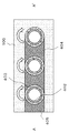
- FIG. 2A shows an outline of the configuration of the power generation system of the present embodiment.
- 2B and 2C are cross-sectional views of FIG. 2A.
- FIG. 2B is a cross-sectional view taken along lines A and A ′ in FIG. 2A.
- FIG. 2C is a cross-sectional view taken along the lines B and B ′ in FIG. 2A.
- the power generation system of the present embodiment includes a main exhaust gas pipe 201, a branched exhaust gas pipe 202, a sheet-type thermoelectric conversion element 203, an electric joint portion 204, and a terminal 205.
- the main exhaust gas pipe 201 is branched into a plurality of branch exhaust gas pipes 202.
- a sheet type thermoelectric conversion element 203 is wound around the branch exhaust gas pipe 202. Winding means attaching the sheet of the sheet type thermoelectric conversion element 203 so as to be wound in the circumferential direction along the surface of the branched exhaust gas pipe 202. Further, the periphery of the branch exhaust gas pipe 202 and the sheet type thermoelectric conversion element 203 is filled with circulating cooling water 100.
- the sheet-type thermoelectric conversion element 203 is in contact with the branched exhaust gas pipe 202 on almost the entire surface of one side and is cooled with the cooling water 100 on the almost entire surface of the other surface.
- the power generation system of the present embodiment can generate power with the sheet-type thermoelectric conversion element 203 based on a temperature difference existing between the high temperature exhaust gas and the low temperature cooling water 100.
- the main exhaust gas pipe 201 is a pipe through which heated exhaust gas flows.
- a fluid such as gas or water vapor with heat discharged from the internal combustion engine flows inside.
- the branch exhaust gas pipe 202 is a pipe branched from the main exhaust gas pipe 201 into a plurality of parts.
- a sheet type thermoelectric conversion element 203 is wound around the branch exhaust gas pipe 202.
- the sheet type thermoelectric conversion element 203 is wound so as to surround the circumference of the branched exhaust gas pipe 202.
- the branch exhaust gas pipe 202 is configured by branching the main exhaust gas pipe 201 into a plurality in the vicinity shown in FIG. 2B. Further, the branch exhaust pipe 202 is coupled in the vicinity shown in FIG. 2C and becomes the main exhaust pipe 201. That is, the fluid flowing inside the main exhaust gas pipe 201 is divided into a plurality of branch exhaust gas pipes 202 at the branch portion. The fluid that has flowed through the branch exhaust gas pipes 202 joins at the joint and flows through the main exhaust gas pipe 201. Further, the branch exhaust gas pipe 202 of the present embodiment corresponds to the pipe 1 of the first embodiment.
- 2A, 2B and 2C show an example in which the main exhaust gas pipe 201 is branched into three branch exhaust gas pipes 202 having a circular cross section.
- 2A, 2B and 2C show an example in which a plurality of branch exhaust pipes 202 are arranged one-dimensionally
- the arrangement of the branch exhaust pipes 202 may have other configurations.
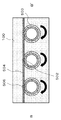
- FIG. 3 shows an example in which a plurality of branched exhaust pipes 31 are two-dimensionally bundled may be used.
- FIG. 3 shows an example in which the branched exhaust pipes 31 around which the sheet type thermoelectric conversion elements 32 are wound are arranged two-dimensionally.
- the number of branch exhaust gas pipes 202 may be four or more, or two.
- the cross-sectional shape of the branched exhaust gas pipe 202 may be other than a circle.
- the cross-sectional structure of the branch exhaust gas pipe 202 may be a square shape such as a square or a polygon.
- the main exhaust gas pipe 201 and the branched exhaust gas pipe 202 are made of metal such as SUS, for example.
- the fluid flowing in the main exhaust pipe 201 and the branched exhaust pipe 202 may be a liquid.
- the sheet-type thermoelectric conversion element 203 is a thermoelectric conversion element that generates a current in the in-plane direction, that is, in the plane direction of the sheet, due to a temperature gradient in a direction perpendicular to the plane of the sheet.
- the sheet-type thermoelectric conversion element 203 is a thermoelectric conversion element in which current flows in one of the in-plane directions.
- a thermoelectric conversion element using a spin Seebeck effect or a thermoelectric conversion element using an abnormal Nernst effect can be used as the sheet-type thermoelectric conversion element 203.
- the direction of the current generated in the sheet type thermoelectric conversion element 203 is determined by the magnetization direction of the sheet type thermoelectric conversion element 203.
- White arrows shown in FIGS. 2B and 2C indicate the direction of magnetization of the sheet type thermoelectric conversion element 203.
- the arrow of FIG. 2A has shown the direction through which the electric current produced by the temperature difference flows.
- each branch exhaust gas pipe 202 be installed at a distance of 10 micrometers or more from the adjacent branch exhaust gas pipe 202.
- thermoelectric conversion efficiency in the temperature region near the exhaust gas inlet is set to be higher than the thermoelectric conversion efficiency in other temperature regions.
- thermoelectric conversion efficiency in the temperature region near the exhaust gas outlet is set to be higher than the thermoelectric conversion efficiency in other temperature regions.
- a material having a Curie temperature higher than that near the exhaust gas outlet is used.
- the sheet-type thermoelectric conversion element 203 of the present embodiment is in contact with the branch exhaust gas pipe 202 on almost the entire surface of one side and is cooled with the cooling water 100 on the almost entire surface of the other surface. Therefore, it is possible to efficiently generate power based on the temperature difference between the gas flowing through the branched exhaust pipe 200 and the cooling water 100. Since the sheet-type thermoelectric conversion element 203 is wound around the branch exhaust gas pipe 202, even if the branch exhaust gas pipe 202 vibrates, desorption is unlikely to occur. Further, since the sheet-type thermoelectric conversion element 203 is wound in almost all the region in the longitudinal direction of the branched exhaust gas pipe 202, the electrode connecting the thermoelectric conversion element in the branched exhaust gas pipe 202 becomes defective.
- thermoelectric conversion element 203 since the sheet-type thermoelectric conversion element 203 is wound around the branch exhaust gas pipe 202, a large space is not required around it when being attached to the branch exhaust gas pipe 202.
- the sheet type thermoelectric conversion element 203 of the present embodiment corresponds to the thermoelectric conversion element 2 of the first embodiment.
- the electrical junction 204 electrically connects each sheet type thermoelectric conversion element 203.
- the electrical joint portion 204 of the present embodiment is attached to the end of each sheet-type thermoelectric conversion element 203 so that adjacent sheet-type thermoelectric conversion elements 203 are electrically connected in series.
- the electrical junction 204 is preferably formed of a low electrical resistance material.
- the electrical joint portion 204 is formed of, for example, a metal such as Cu, Ag, Al, and Ti, or an alloy containing these elements.
- the terminal 205 is provided as a connection terminal for taking out current from the sheet-type thermoelectric conversion element 203 that is electrically connected in series.
- the terminals 205 are provided at positions on both ends of the sheet-type thermoelectric conversion elements 203 connected in series via the electric joint portions 204.
- the terminal 205 is connected to a circuit that transmits power generated by the sheet-type thermoelectric conversion element 203, a battery that stores electricity, and the like.
- the cooling water 100 is a fluid that cools the heat-carrying gas flowing in the branch exhaust gas pipe 202.
- the cooling water 100 is in a reverse flow state with respect to the direction of gas flow in the branch exhaust gas pipe 202, that is, the direction of the cooling water 100 and the direction of the exhaust gas are reversed. Since the cooling water 100 and the exhaust gas flow in directions opposite to each other, the cooling efficiency is improved because the coolant contacts the cooling water having a low temperature at the position where the temperature of the exhaust gas near the outlet of the branch exhaust gas pipe 202 is lowered.
- the facing directions do not have to be parallel to each other, and it is only necessary that the cooling water 100 flows so that the temperature of the surrounding cooling water 100 decreases as the gas advances through the branched exhaust gas pipe 202. Further, since the temperature difference between the cooling water 100 and the exhaust gas can be maintained on both sides of the branch exhaust gas pipe 202 near the exhaust gas inlet and the outlet, the power generation efficiency is improved.
- the cooling water 100 may be forward flow with respect to the direction of gas flow in the branch exhaust gas pipe 22, that is, the direction of the cooling water and the direction of the exhaust gas may be the same.
- the cooling water 100 may be a liquid other than water, or may be a mixture of water and other substances. Further, instead of the cooling water 100, air for air cooling may be flowed.
- thermoelectric conversion unit is configured by a plurality of branched exhaust pipes 202, a sheet-type thermoelectric conversion element 203, an electric joint 204, a terminal 205, and a cooling water 100 flow path.
- the sheet type thermoelectric conversion element 203 has a structure in which the surface is covered with a waterproof film in order to come into contact with cooling water during operation.
- the sheet-type thermoelectric conversion element 203 is in a state of being magnetized in the in-plane direction, that is, the planar direction of the sheet. Magnetization is performed, for example, by applying a magnetic field to a sheet on which a magnetic film is formed.
- the magnetized sheet type thermoelectric conversion element 203 is wound around the branch exhaust gas pipe 202. Winding is performed so that the direction of magnetization of each sheet-type thermoelectric conversion element 203 is the circumference of the branch exhaust gas pipe 202. Each sheet type thermoelectric conversion element 203 is wound so that the circumferential direction of magnetization is alternated between adjacent sheet type thermoelectric conversion elements 203.
- an electric joint portion 204 is attached to the end of the sheet-type thermoelectric conversion element 203 so that the sheet-type thermoelectric conversion element 203 is electrically connected in series.
- the electric joint portion 204 may come into contact with the cooling water 100, it is configured to be covered with a waterproof film.
- the terminals 205 are attached to the sheet-type thermoelectric conversion elements 203 at both ends of the sheet-type thermoelectric conversion elements 203 electrically connected in series.
- the terminal 205 is attached, the cooling water 100 is attached.
- the method for constructing the power generation system may be performed by methods other than those described above.
- one end of the electrical junction 204 may be connected in advance to one end of the predetermined sheet-type thermoelectric conversion element 203 when the sheet-type thermoelectric conversion element 203 is wound around the branch exhaust gas pipe 202.
- the sheet-type thermoelectric conversion element 203 is wound around the branch exhaust gas pipe 202 attached in advance, but the branch exhaust gas pipe 202 around which the sheet-type thermoelectric conversion element 203 is wound is used as the main exhaust gas. It may be connected to the tube 201.
- high-temperature gas flows inside the main exhaust gas pipe 201.
- the gas that has flowed through the main exhaust gas pipe 201 branches to each branch exhaust gas pipe 202 at the branch portion between the main exhaust gas pipe 201 and the branch exhaust gas pipe 202 and flows through each branch exhaust gas pipe 202.
- the gas flowing through each branch exhaust pipe 202 joins at the connection between the branch exhaust pipe 202 and the main exhaust pipe 201 and flows through the main exhaust pipe 201 to be discharged.
- adjacent sheet-type thermoelectric conversion elements 203 are connected by an electric joint 204, and the magnetization direction is set so that currents flow in directions opposite to each other with respect to the longitudinal direction of the branch exhaust gas pipe 202. . Therefore, the current flowing through each sheet type thermoelectric conversion element 203 can be taken out from both ends of the plurality of sheet type thermoelectric conversion elements 203 in an electrically serial state via the terminal 205.
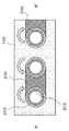
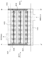
- FIG. 4A shows a configuration of a power generation system when a sheet type abnormal Nernst thermoelectric conversion element 603 using an abnormal Nernst effect is joined in series as a sheet type thermoelectric conversion element.
- 4B and 4C are cross-sectional views of FIG. 4A.
- 4B is a cross-sectional view taken along the line A and A ′ in FIG. 4A.
- FIG. 4C is a cross-sectional view taken along lines B and B ′ in FIG. 4A.
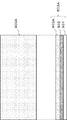
- FIG. 5 shows a configuration of the sheet type abnormal Nernst thermoelectric conversion element 603.
- the sheet-type abnormal Nernst thermoelectric conversion element 603 includes a substrate 701 and a magnetic film 702.
- the upper part of FIG. 5 is a diagram when the plane of the sheet type abnormal Nernst thermoelectric conversion element 603 is viewed from above.
- the lower part of FIG. 5 is a cross-sectional view of the sheet type abnormal Nernst thermoelectric conversion element 603.
- a magnetic film 702 is formed on the substrate 701 as an abnormal Nernst thermoelectric conversion film having a composition gradient.
- the substrate 701 for example, an aluminum nitride substrate having high temperature resistance and high thermal conductivity is used.
- the magnetic film 702 is formed on the substrate 901 by a composition combinatorial sputtering method that gives a composition gradient.
- the compositional combinatorial sputtering method is a method of creating a film having a composition gradient on the same substrate.
- a magnetic film 702 is formed on the sheet type abnormal Nernst thermoelectric conversion element 603 so as to have a composition gradient in the longitudinal direction when wound around the branch exhaust gas pipe 602.
- an FeCoPt alloy film is used for the magnetic film 702.
- the magnetic film 702 is formed such that the Co-rich composition, that is, the Co composition is higher toward the left side of FIG. 5, and the Fe-rich composition, that is, the Fe composition is higher toward the right side.
- the Co-rich composition increases the Curie temperature, but decreases the thermoelectric conversion efficiency.
- the Fe-rich composition increases the thermoelectric conversion efficiency but decreases the Curie temperature.
- the magnetic film 702 is magnetized. Magnetization is performed in the in-plane direction of the sheet type abnormal Nernst thermoelectric conversion element 603, that is, in the plane direction of the sheet. Magnetization is performed in a direction perpendicular to the direction of the Fe—Co composition gradient of the magnetic film 702.
- the magnetized sheet type abnormal Nernst thermoelectric conversion element 603 is attached to the branch exhaust gas pipe 602.
- the cross-sectional shape of the branch exhaust gas pipe 602 is a quadrangle. Therefore, four sheet type abnormal Nernst thermoelectric conversion elements 603 are attached to one branch exhaust gas pipe 602.
- the sheet-type abnormal Nernst thermoelectric conversion element 603 is attached so that the direction in which the Fe—Co composition gradient is provided is the longitudinal direction of the branch exhaust gas pipe 602. Further, the attachment is performed so that the inlet side of the exhaust gas, that is, the vicinity shown in FIG. 4B has a Co-rich composition, and the vicinity of the exhaust gas outlet, that is, the vicinity shown in FIG. 4C has a Fe-rich composition.
- the magnetization direction of the sheet type abnormal Nernst thermoelectric conversion element 603 attached around each branch exhaust gas pipe 602 is made to alternate between the adjacent branch exhaust gas pipes 602.
- the magnetization direction is clockwise
- the center branch exhaust pipe 602 is counterclockwise
- the rightmost branch exhaust pipe 602 is clockwise.
- the four sheet type abnormal Nernst thermoelectric conversion elements 603 are formed of Cu so that the four sheets of abnormal Nernst thermoelectric conversion elements 603 are electrically joined to the four corners of each branch exhaust gas pipe 802.
- the electrical junction 606 is attached.
- the electrical joints 606 When the electrical joints 606 are attached to the four corners of each branch exhaust gas pipe 602, the electrical joints 604 formed of Cu are attached so that the branch exhaust gas pipes 602 are electrically joined in series. Is called.
- the sheet type abnormal Nernst thermoelectric conversion element 603, the electrical joint portion 604, and the electrical joint portion 606 are covered with a waterproof film so as not to touch the cooling water, except for the electrically joined portions.
- FIG. 4A, 4B and 4C show a structure in which the main exhaust gas pipe 601 is branched into three branched exhaust gas pipes 602 having a square cross section, and the branched exhaust gas pipes 602 are arranged one-dimensionally.
- the number and arrangement of the exhaust gas pipes 602 may be other structures.
- the number of branch exhaust gas pipes 602 may be other than three, and may have a two-dimensionally bundled structure as shown in FIG.
- the cross-sectional structure of the exhaust gas pipe is not a quadrangle, but may be a polygon or a circle.
- thermoelectric conversion element 603 is attached to each surface of the branched exhaust pipe 602 and electrically connected by the electrical joint 606.
- the thermoelectric conversion element 603 may be continuous.
- the flowing direction of the cooling water 100 is a reverse flow, but it may be a forward flow.
- an air cooling method may be used instead of the cooling method using the cooling water 100.
- a high-temperature liquid may be allowed to flow in the main exhaust gas pipe 601 and the branched exhaust gas pipe 602 instead of the exhaust gas.
- a sheet type thermoelectric conversion element is wound around a plurality of branch exhaust gas pipes branched from the main exhaust gas pipe.
- the sheet-type thermoelectric conversion element it is possible to suppress a space when being attached to the branch exhaust gas pipe, and thus it is possible to densely provide the branch exhaust gas pipe.
- the surface area where the sheet-type thermoelectric conversion element and the branched exhaust pipe are in contact is increased by densely arranging the branched exhaust pipes branched from the main exhaust pipe.
- the area where the sheet-type thermoelectric conversion element and the branch exhaust pipe are in contact with each other over the entire circumference is wide even for one branch exhaust pipe. Therefore, the power generation system of this embodiment has high power generation efficiency.
- the sheet type thermoelectric conversion element is wound so as to be in contact with the entire circumference of the branch exhaust gas pipe. For this reason, even when vibration is generated in the branch exhaust gas pipe, the sheet-type thermoelectric conversion element is hardly detached from the branch exhaust gas pipe.
- the sheet-type thermoelectric conversion element is continuously wound in the longitudinal direction of the branch exhaust gas pipe, an electrode for connecting the thermoelectric conversion elements in the same branch exhaust gas becomes unnecessary. Therefore, in the power generation system of the present embodiment, reliability is improved by suppressing the occurrence of disconnection and detachment while simplifying the structure. As a result, the power generation system according to the present embodiment can efficiently generate power based on thermal energy while maintaining reliability without complicating the configuration.
- FIG. 6A shows an outline of the configuration of the power generation system of the present embodiment.
- 6B and 6C are cross-sectional views of FIG. 6A.
- 6B is a cross-sectional view taken along the line A and A ′ in FIG. 6A.
- FIG. 6C is a cross-sectional view taken along the lines B and B ′ in FIG. 6A.
- the power generation system of the present embodiment includes a main exhaust pipe 301, a branched exhaust pipe 302, a first sheet type thermoelectric conversion element 303A, a second sheet type thermoelectric conversion element 303B, an electrical joint 304, and a terminal 305. It has.
- the periphery of the branch exhaust gas pipe 302 and each sheet type thermoelectric conversion element is filled with circulating cooling water 100.
- the current flowing in the magnetization direction is the same and the current flows in the opposite direction between the adjacent sheet type thermoelectric conversion elements depending on the direction in which the sheet type thermoelectric conversion elements are attached.
- This embodiment is characterized in that the sheet-type thermoelectric conversion element is formed using a material in which the direction of current flow is opposite even in the same magnetization direction instead of such a configuration.
- the configurations of the main exhaust pipe 301 and the branched exhaust pipe 302 are the same as the configurations of the main exhaust pipe 201 and the branched exhaust pipe 202 of the second embodiment, respectively.
- the first sheet type thermoelectric conversion element 303A and the second sheet type thermoelectric conversion element 303B have a temperature gradient in a direction perpendicular to the plane of the sheet. It is a thermoelectric conversion element that generates a current in the in-plane direction.
- the first sheet type thermoelectric conversion element 303A and the second sheet type thermoelectric conversion element 303B are formed, for example, as thermoelectric conversion elements using the spin Seebeck effect.
- the materials used for the first sheet-type thermoelectric conversion element 303A and the second sheet-type thermoelectric conversion element 303B are different from each other.
- the first sheet type thermoelectric conversion element 303A is formed of a material having a positive spin Hall angle.
- the second sheet type thermoelectric conversion element 303B is made of a material having a negative spin Hall angle. When the signs of the spin Hall angles are different, the current generation direction is reversed even in the same magnetization direction.
- the first sheet type thermoelectric conversion element 303A and the second sheet type thermoelectric conversion element 303B are alternately wound around the branch exhaust gas pipe 302. Since the periphery is filled with circulating cooling water 100, the first sheet type thermoelectric conversion element 303 ⁇ / b> A and the second sheet type thermoelectric conversion element are caused by a temperature difference existing between the high temperature exhaust gas and the low temperature cooling water 100. 303B can generate electricity.
- the first sheet type thermoelectric conversion element 303A and the second sheet type thermoelectric conversion element 303B are magnetized in the circumferential direction of the branched exhaust gas pipe 302. Therefore, a current generated due to a temperature difference between the exhaust gas and the cooling water 100 is generated in the longitudinal direction of the branch exhaust gas pipe 302.
- first sheet-type thermoelectric conversion element 303A and the second sheet-type thermoelectric conversion element 303B have the same magnetization direction in the circumferential direction, but have different material spin codes. Therefore, the directions of currents generated in the first sheet type thermoelectric conversion element 303A and the second sheet type thermoelectric conversion element 303B are opposite to each other.
- thermoelectric conversion efficiency in the temperature region near the exhaust gas inlet is higher than the thermoelectric conversion efficiency in other temperature regions, and the Curie temperature is higher than the temperature near the exhaust gas inlet.
- thermoelectric conversion efficiency in the temperature region near the exhaust gas outlet is higher than the thermoelectric conversion efficiency in other temperature regions, and the Curie temperature is higher than the temperature near the exhaust gas outlet.
- the electrical junction 304 is attached to the ends of the first sheet type thermoelectric conversion element 303A and the second sheet type thermoelectric conversion element 303B so that the sheet type thermoelectric conversion elements are electrically connected in series. . It is desirable that the electrical junction 304 is made of a low electrical resistance material.
- the electrical joint 304 is formed of a metal such as Cu, Ag, Al, and Ti or an alloy containing these elements.
- the terminal 305 is provided as a connection terminal for taking out an electric current from the sheet type thermoelectric conversion element connected so as to be electrically connected in series.
- the adjacent sheet-type thermoelectric elements are bundled. Magnetization between the conversion elements interacts so as to enhance each other. Therefore, in consideration of the magnetization stability of the first sheet type thermoelectric conversion element 303A and the second sheet type thermoelectric conversion element 303B, the distance between the branched exhaust pipes 302 is set to 10 centimeters or less. It is desirable.
- a fluid having a higher magnetic permeability than water may be used as the cooling water 100.
- a magnetic fluid in which ferromagnetic fine particles such as magnetite and manganese zinc ferrite are mixed with a liquid or an MR (Magneto-Rheological) fluid can be used.
- 6A, 6B, and 6C show a configuration in which the main exhaust pipe 301 is branched into three branched exhaust pipes 302 having a circular cross section, and the branched exhaust pipes 302 are arranged one-dimensionally.
- the number of branch exhaust pipes 302 may be other than three.
- the branched exhaust gas pipes 302 may be structured to be two-dimensionally bundled.
- the cross-sectional structure of the branched exhaust gas pipe 302 may be a square shape such as a quadrangle instead of a circle.
- FIG. 6A shows the configuration in which the cooling water 100 is in the reverse flow
- the cooling water may be a forward flow with respect to the direction of the exhaust gas.
- cooling by air cooling may be performed instead of the cooling method using the cooling water 100.
- the first sheet type thermoelectric conversion element 303A and the second sheet type thermoelectric conversion element 303B are formed of materials having different signs of the spin hole angle.
- the first sheet type thermoelectric conversion element 303A is formed of a material having a positive spin hole angle, such as a metal such as Pt, Au, Co, Ni, and Ag, or an alloy including them.
- the second sheet-type thermoelectric conversion element 303B is formed of a material having a negative spin hole angle, such as a metal such as W, Fe, Mn, Ru, Os, and Cr, or an alloy containing them.
- the first sheet type thermoelectric conversion element 303A and the second sheet type thermoelectric conversion element 303B are in contact with the cooling water during operation, and thus are covered with a waterproof film on the surface.
- the first sheet type thermoelectric conversion element 303A and the second sheet type thermoelectric conversion element 303B are magnetized in the in-plane direction after the magnetic film is formed. After being magnetized, the first sheet type thermoelectric conversion element 303A and the second sheet type thermoelectric conversion element 303B are wound around the branch exhaust gas pipe 302. The winding is such that the magnetization direction of the first sheet type thermoelectric conversion element 303A and the second sheet type thermoelectric conversion element 303B is the circumference of the branch exhaust gas pipe 302, and the direction of the magnetization circumferential direction is each sheet. The same is applied to the type spin thermoelectric conversion element.
- the electric junction 304 is attached to the end of each sheet type thermoelectric conversion element so that the first sheet type thermoelectric conversion element 303A and the second sheet type thermoelectric conversion element 303B are alternately joined in series. Is attached. Moreover, since the electrical junction part 304 may be in contact with cooling water, it is covered with a waterproof film. Further, the power generation system may be constructed by a method other than the above.
- the terminal 305 for taking out electric power to the outside is attached to the sheet-type thermoelectric conversion element that becomes both ends when connected in series.
- the flow path of the cooling water 100 is attached.
- the terminal 305 is connected to a circuit or a battery to which power is supplied.
- high-temperature gas flows inside the main exhaust gas pipe 301.
- the gas flowing through the main exhaust gas pipe 301 branches to each branch exhaust gas pipe 302 at the connecting portion between the main exhaust gas pipe 301 and the branch exhaust gas pipe 302, and flows through each branch exhaust gas pipe 302.
- the gas flowing through each branch exhaust pipe 302 joins at the connection between the branch exhaust pipe 302 and the main exhaust pipe 301 and flows through the main exhaust pipe 301 to be discharged.
- the temperature in the direction perpendicular to the plane of the sheets of the first sheet type thermoelectric conversion element 303A and the second sheet type thermoelectric conversion element 303B is caused by the temperature difference between the exhaust gas and the cooling water 100. There is a difference.
- a temperature difference is generated in the vertical direction of the sheet, an electric current is generated in the first sheet type thermoelectric conversion element 303A and the second sheet type thermoelectric conversion element 303B in the longitudinal direction of the branched exhaust gas pipe 302.
- the first sheet type thermoelectric conversion element 303A and the second sheet type thermoelectric conversion element 303B have opposite signs of the spin Hall angles, the currents are opposite to each other in the longitudinal direction.
- adjacent sheet-type thermoelectric conversion elements are connected by an electrical joint 304, and currents flow in directions opposite to each other with respect to the longitudinal direction of the branched exhaust gas pipe 302. Therefore, electric power can be obtained by taking out the current that alternately flows through the first sheet type thermoelectric conversion element 303 ⁇ / b> A and the second sheet type thermoelectric conversion element 303 ⁇ / b> B through the terminal 505.
- FIG. 7A shows a configuration of a power generation system when sheet-type spin Seebeck thermoelectric conversion elements having different signs of spin Hall angles are alternately connected in series as sheet-type thermoelectric conversion elements.
- the sheet-type spin Seebeck thermoelectric conversion element 803A corresponds to the first sheet-type thermoelectric conversion element 303A.
- the sheet type spin Seebeck thermoelectric conversion element 803B corresponds to the second sheet type thermoelectric conversion element 303B.
- 7B and 7C are cross-sectional views of FIG. 7A.
- FIG. 7B is a cross-sectional view taken along lines A and A ′ in FIG. 7A.
- FIG. 7C is a cross-sectional view taken along the lines B and B ′ in FIG. 7A.
- FIG. 8 shows the configuration of a sheet-type spin Seebeck thermoelectric conversion element 803A.
- FIG. 9 shows the configuration of a sheet-type spin Seebeck thermoelectric conversion element 803B.
- 8 and 9 are diagrams when the plane of the sheet-type spin Seebeck thermoelectric conversion element is viewed from above. 8 and 9 are cross-sectional views of the sheet-type spin Seebeck thermoelectric conversion element.
- a magnetic insulating film 902 and a metal film 903A or a metal film 903 are formed on a substrate 901.
- a substrate 901 for example, a flexible sheet using AlN fine particles is used.
- a magnetic insulating film 902 is formed on the substrate 901.
- NiZn is deposited on the magnetic insulating film 902 by a ferrite plating method.
- the ferrite plating method is a method for creating a flexible ferrite thin film.
- the metal film 903A or the metal film 903B is formed on the magnetic insulating film 902 by a sputtering method.
- a material having a positive sign of the spin hole angle is used for the metal film 903A.
- Pt having a positive sign of the spin Hall angle is used for the metal film 903A.
- a material having a negative sign of the spin hole angle is used for the metal film 903B.
- W having a negative spin Hall angle is used.
- the magnetized sheet-type spin Seebeck thermoelectric conversion element 803A and the sheet-type spin Seebeck thermoelectric conversion element 803B are attached to the branch exhaust gas pipe 802.
- the sheet-type spin Seebeck thermoelectric conversion element 803A and the sheet-type spin Seebeck thermoelectric conversion element 803B are wound around the branch exhaust gas pipe 802 so that the magnetization direction is the circumferential direction of the branch exhaust gas pipe 802.
- the sheet-type spin Seebeck thermoelectric conversion element 803A and the sheet-type spin Seebeck thermoelectric conversion element 803B are arranged so as to alternate with each other, and are wound around the branch exhaust gas pipe 802 so that the circumferential magnetization directions are the same. It is done.
- a sheet-type spin Seebeck thermoelectric conversion element 803A is wound around the leftmost branch exhaust gas pipe 802, and a sheet-type spin Seebeck thermoelectric conversion element 803B is wound around the central branch exhaust gas pipe 802.
- a sheet-type spin Seebeck thermoelectric conversion element 803A is wound around the rightmost branched exhaust pipe 802 in FIGS. 7B and 7C. Further, the magnetization directions of all the sheet type spin Seebeck thermoelectric conversion elements 803A and the sheet type spin Seebeck thermoelectric conversion elements 803B are clockwise.
- the electrical junction 804 made of, for example, Cu is attached so that the sheet-type spin Seebeck thermoelectric conversion element 803A and the sheet-type spin Seebeck thermoelectric conversion element 803B are electrically joined in series. Is called. Further, as the cooling water 100, for example, a magnetic fluid using magnetite fine particles is used.
- the sheet-type spin Seebeck thermoelectric conversion element 803A, the sheet-type spin Seebeck thermoelectric conversion element 803B, and the electrical junction 804 are covered with a waterproof film so as not to touch the magnetic fluid.
- the terminal 805 is attached to the spin Seebeck thermoelectric conversion element that becomes both ends when connected in series.
- the sheet-type spin Seebeck thermoelectric conversion element 803A and the sheet-type spin Seebeck thermoelectric conversion element 803B are caused by a temperature difference generated between the branch exhaust gas pipe 802 and the magnetic fluid that is the cooling water 100. Generate electricity.
- the electric power generated in the sheet-type spin Seebeck thermoelectric conversion element 803A and the sheet-type spin Seebeck thermoelectric conversion element 803B can be taken out through the terminal 805 and used.
- FIG. 7A, FIG. 7B, and FIG. 7C show a configuration in which the main exhaust gas pipe 801 branches into three branch exhaust gas pipes 802 having a circular cross section and is arranged one-dimensionally. The number may be other than three or may be a two-dimensionally bundled structure. Further, the cross-sectional structure of the exhaust gas pipe is not circular but may be square such as a quadrangle.
- the cooling water 100 is in a reverse flow, but may be a forward flow with respect to the direction of the exhaust gas. Moreover, it may replace with the cooling method by cooling water, and may use an air cooling system. Further, instead of the exhaust gas, a high-temperature liquid may flow through the main exhaust gas pipe 801 and the branched exhaust gas pipe 802.
- the power generation system of this embodiment has the same effect as that of the second embodiment. That is, the power generation system according to the present embodiment can efficiently generate power based on thermal energy while maintaining reliability without complicating the configuration. Further, in the power generation system of the present embodiment, the generated current flows in different directions by using sheet-type thermoelectric conversion elements formed of materials having different spin Hall angles. Therefore, in the power generation system of this embodiment, since the magnetization directions of all the sheet type thermoelectric conversion elements are the same, it is possible to suppress complication when performing work.
- FIG. 10A shows an outline of the configuration of the power generation system of the present embodiment.
- 10B and 10C are cross-sectional views of FIG. 10A.
- FIG. 10B is a cross-sectional view taken along lines A and A ′ in FIG. 10A.
- FIG. 10C is a cross-sectional view taken along lines B and B ′ in FIG. 10A.
- the power generation system of the present embodiment includes a main exhaust gas pipe 401, a branched exhaust gas pipe 402, a sheet-type thermoelectric conversion element 403, an electric joint 404, and a terminal 405.
- the periphery of the branch exhaust pipe 402 and each sheet type thermoelectric conversion element is filled with circulating cooling water 100.
- thermoelectric conversion elements In the second embodiment, a plurality of sheet-type thermoelectric conversion elements are connected so as to be electrically in series, but in this embodiment, the sheet-type thermoelectric conversion elements are connected in parallel.
- the configurations of the main exhaust pipe 401 and the branch exhaust pipe 402 are the same as the main exhaust pipe 201 and the branch exhaust pipe 202 of the second embodiment, respectively.
- the sheet-type thermoelectric conversion element 403 is a thermoelectric element that generates a current in the in-plane direction, that is, the plane direction, due to a temperature gradient in a direction perpendicular to the plane of the sheet. It is a conversion element.
- the direction of the current generated in the sheet type thermoelectric conversion element 403 is determined by the magnetization direction of the sheet type thermoelectric conversion element 403 and the sign of the spin hole angle of the material. Therefore, by magnetizing the sheet-type thermoelectric conversion element 403 in the circumferential direction of the branch exhaust gas pipe 402, a current generated due to a temperature difference is generated in the longitudinal direction of the branch exhaust gas pipe 402. Moreover, since the direction of the magnetization concerning the circumferential direction of each sheet type thermoelectric conversion element 403 is the same, the direction of the electric current which generate
- the sheet-type thermoelectric conversion element 403 of the present embodiment is formed as a thermoelectric conversion element using a spin Seebeck effect or an abnormal Nernst effect.
- the electrical joining portion 404 is attached to the end of each sheet type thermoelectric conversion element 403 so that each sheet type thermoelectric conversion element 403 is electrically joined in parallel.
- the electrical junction 404 is preferably formed of a low electrical resistance material.
- the electrical joint 404 is made of, for example, a metal such as Cu, Ag, Al, and Ti or an alloy containing these elements.
- the generated current is taken out from terminals 405 attached to both ends of any sheet type thermoelectric conversion element.
- the distance between the branched exhaust gas pipes 402 is set to 10 centimeters or less.
- a magnetic material obtained by mixing a fluid having higher permeability than water as the cooling water 100 for example, ferromagnetic fine particles such as magnetite and manganese zinc ferrite in the liquid.
- a fluid or MR fluid may be used.
- FIG. 10A, FIG. 10B, and FIG. 10C have a structure in which the main exhaust pipe 401 is branched into three branched exhaust pipes 402 having a circular cross section, and they are arranged one-dimensionally.
- the number of the branched exhaust pipes 402 may be other than three, and the branched exhaust pipes 402 may have a two-dimensionally bundled structure as shown in FIG.
- the cross-sectional structure of the exhaust gas pipe is not circular but may be square such as a quadrangle.
- thermoelectric conversion efficiency in the temperature region near the exhaust gas inlet is higher than the thermoelectric conversion efficiency in other temperature regions, and the Curie temperature is higher than the temperature near the exhaust gas inlet.
- thermoelectric conversion efficiency in the temperature region near the exhaust gas outlet is higher than the thermoelectric conversion efficiency in other temperature regions, and the Curie temperature is higher than the temperature near the exhaust gas outlet.
- FIG. 10A shows a configuration in which the cooling water has a reverse flow, but the cooling water may be a forward flow with respect to the direction of the exhaust gas. Further, cooling by air cooling may be performed instead of the cooling method by cooling water.
- the fluid flowing in the main exhaust pipe 401 and the branch exhaust pipe 402 may be a liquid.
- thermoelectric conversion element 403 is created. Since the sheet-type thermoelectric conversion element 403 is in contact with cooling water during operation, the surface needs to be covered with a waterproof film.
- the sheet-type thermoelectric conversion element 403 is magnetized in the in-plane direction after the magnetic film is formed.
- the magnetized sheet type thermoelectric conversion element 403 is wound around the branch exhaust gas pipe 402.
- each sheet type thermoelectric conversion element 403 has a magnetization direction that is the circumference of the branch exhaust gas pipe 402, and the direction of the magnetization circumferential direction is the same in each sheet type thermoelectric conversion element 403. So that it is wound.
- the electric joint 404 is attached to the end so that the sheet-type thermoelectric conversion elements 403 are joined in parallel. Since the electrical joint 404 may come into contact with the cooling water 100, it is covered with a waterproof film. Terminals 405 are attached to both ends of any of the sheet type thermoelectric conversion elements.
- high-temperature gas flows inside the main exhaust gas pipe 401.
- the gas that has flowed through the main exhaust gas pipe 401 branches to each branch exhaust gas pipe 402 at the connection portion between the main exhaust gas pipe 401 and the branch exhaust gas pipe 402 and flows in each branch exhaust gas pipe 402.
- the gas flowing in each branch exhaust pipe 402 joins at the connection portion between the branch exhaust pipe 402 and the main exhaust pipe 401 and flows through the main exhaust pipe 401 and is discharged.
- thermoelectric conversion element 403 When the gas flows in the branch exhaust gas pipe 402, a temperature difference is generated in a direction perpendicular to the plane of the sheet of the sheet type thermoelectric conversion element 403 due to a temperature difference between the gas and the cooling water 100. Due to the temperature difference in the vertical direction of the sheet, an electric current is generated in the sheet-type thermoelectric conversion element 403 in the longitudinal direction of the branch exhaust pipe 402.
- adjacent sheet-type thermoelectric conversion elements 403 are connected by an electrical joint 404, and current flows in parallel in the same direction with respect to the longitudinal direction of the branched exhaust gas pipe 402. Therefore, electric power can be obtained by taking out the current flowing through the sheet-type thermoelectric conversion elements 403 connected in parallel through the terminal 405.
- the power generation system of this embodiment has the same effect as that of the second embodiment. That is, the power generation system according to the present embodiment can efficiently generate power based on thermal energy while maintaining reliability without complicating the configuration. Further, in the power generation system of the present embodiment, current flows in the same direction with respect to the branch exhaust pipe in all the sheet type thermoelectric conversion elements, and since the currents are electrically connected in parallel, the output current can be increased. .
- FIG. 11A shows an outline of the configuration of the power generation system of the present embodiment.
- the power generation system of the present embodiment includes a main exhaust gas pipe 501, a branched exhaust gas pipe 502, a sheet type thermoelectric conversion element 503, an electrical joint 504, a terminal 505, and an insulating part 506.
- the branch exhaust gas pipe 502 and each sheet type thermoelectric conversion element 503 are filled with circulating cooling water 100.
- the current flowing in the longitudinal direction that is, the direction in which the gas flows in the branch exhaust gas pipe
- the power generation system of this embodiment flows in the direction along the circumference of the branch exhaust gas pipe 502. It is characterized by using a current.
- the configuration of the main exhaust pipe 501 and the branch exhaust pipe 502 is the same as that of the main exhaust pipe 201 and the branch exhaust pipe 202 of the second embodiment.
- the sheet-type thermoelectric conversion element 503 is magnetized in the longitudinal direction of the branch exhaust gas pipe 502, and generates a current in the circumferential direction of the branch exhaust gas pipe 502 due to a temperature difference perpendicular to the plane of the sheet. Moreover, the direction of magnetization in the longitudinal direction of each sheet type thermoelectric conversion element 503 is the same. Therefore, the direction of the current generated in the circumferential direction in each sheet type thermoelectric conversion element 503 is the same. As the sheet-type thermoelectric conversion element 503, a thermoelectric conversion element using a spin Seebeck effect or an abnormal Nernst effect is used.
- each sheet type thermoelectric conversion element 503 is insulated by an insulating portion 506.
- an electrical junction 504 is attached at the end in the longitudinal direction of each sheet-type thermoelectric conversion element 503, so that each sheet-type thermoelectric conversion element 503 is electrically connected in series.
- the electrical junction 504 is preferably made of a low electrical resistance material.
- the electrical joint 504 is formed of, for example, a metal such as Cu, Ag, Al, and Ti, or an alloy containing these elements. The generated current is taken out via the terminal 505.
- each branch exhaust gas pipe 502 be installed at a distance of 10 micrometers or more from the adjacent branch exhaust gas pipe 502.
- FIG. 11A, FIG. 11B, and FIG. 11C show a configuration in which the branched exhaust gas pipe 502 is branched into three branched exhaust gas pipes 502 having a circular cross section, and they are arranged one-dimensionally.
- the number of the branched exhaust pipes 502 may be other than three, or the branched exhaust pipes 502 may be two-dimensionally bundled.
- the cross-sectional structure of the exhaust gas pipe is not circular but may be square such as a quadrangle.
- thermoelectric conversion efficiency in the temperature region near the exhaust gas inlet is higher than the thermoelectric conversion efficiency in other temperature regions, and the Curie temperature is higher than the temperature near the exhaust gas inlet.
- thermoelectric conversion efficiency in the temperature region near the exhaust gas outlet is higher than the thermoelectric conversion efficiency in other temperature regions, and the Curie temperature is higher than the temperature near the exhaust gas outlet.
- FIG. 11A shows a configuration in which the cooling water 100 has a reverse flow, but the cooling water 100 may be a forward flow with respect to the direction of the exhaust gas. Further, instead of the cooling method using the cooling water 100, cooling by air cooling may be performed. Further, instead of the exhaust gas, a high-temperature liquid may flow through the main exhaust gas pipe 501 and the branched exhaust gas pipe 502.
- the in-plane magnetization of the sheet type thermoelectric conversion element 503 is performed.
- the magnetized sheet type thermoelectric conversion element 503 is wound around the branch exhaust gas pipe 502.
- each sheet type thermoelectric conversion element 503 is wound so that the magnetization direction is the longitudinal direction of the branch exhaust gas pipe 502 and the magnetization direction is the same in each sheet type thermoelectric conversion element 503.
- the electric joint portion 504 is attached to the end so that the sheet type thermoelectric conversion elements 503 are joined in series.
- the electrical joint portion 504 since the electrical joint portion 504 may come into contact with the cooling water, it is covered with a waterproof film.
- a terminal 505 for taking out electric power is attached to the sheet-type thermoelectric conversion element 503 that becomes both ends when connected in series, and is connected to a circuit to be supplied with electric power.
- high-temperature gas flows inside the main exhaust gas pipe 501.
- the gas flowing through the main exhaust gas pipe 501 branches to each branch exhaust gas pipe 502 at the connecting portion between the main exhaust gas pipe 501 and the branch exhaust gas pipe 502 and flows in each branch exhaust gas pipe 502.
- the gas flowing in each branch exhaust pipe 502 joins at the connection portion between the branch exhaust pipe 502 and the main exhaust pipe 501, flows through the main exhaust pipe 501, and is discharged.
- a temperature difference is generated in a direction perpendicular to the plane of the sheet of the sheet thermoelectric conversion element 503 due to a temperature difference between the gas and the cooling water 100. Due to the temperature difference in the vertical direction of the sheet, a current is generated in the sheet-type thermoelectric conversion element 503 in the circumferential direction of the branched exhaust gas pipe 502.
- adjacent sheet-type thermoelectric conversion elements 503 are connected by electrical joints 504, and current flows in the same direction with respect to the circumferential direction of the branch exhaust pipe 502 in each sheet-type thermoelectric conversion element 503. Yes. Therefore, electric power can be obtained by taking out the current flowing through the sheet type thermoelectric conversion element 503 via the terminals 505 formed in the sheet type thermoelectric conversion elements 503 at both ends.
- the power generation system of this embodiment has the same effect as that of the second embodiment. That is, the power generation system according to the present embodiment can efficiently generate power based on thermal energy while maintaining reliability without complicating the configuration. Moreover, in the power generation system of this embodiment, in all the sheet type thermoelectric conversion elements, a current flows in the same circumferential direction with respect to the branch exhaust gas pipe, and a direction perpendicular to the direction in which the current flows is long. For this reason, even if a part of the sheet type thermoelectric conversion element is damaged, the sheet type thermoelectric conversion element is hardly affected, so that reliability is improved.
- thermoelectric conversion units examples of straight branched exhaust gas pipes are shown, but all or part of the branched exhaust gas pipes may be curved.
- the flow path of the cooling water inside the thermoelectric converter may be partitioned into a plurality of sections.
- a configuration in which only one thermoelectric conversion unit is provided is shown, but a plurality of thermoelectric conversion units may be formed.
- the configurations of the power generation systems of the second to fifth embodiments may be applied to a multi-stage cooling system.
- a multi-stage cooling system for example, the temperature at which the first fluid flowing through the main exhaust pipe is branched to the branch exhaust pipe and cooled by the second fluid having a temperature lower than that of the first fluid. Based on the difference, the first power generation is performed by the sheet-type thermoelectric conversion element.
- the second fluid is guided to another thermoelectric conversion unit, and the second power generation is performed by the sheet-type thermoelectric conversion element based on the temperature difference when cooling with the third fluid having a temperature lower than that of the second fluid. I do.
- thermoelectric conversion element of the thermoelectric conversion section that performs the second stage cooling is a sheet type that has higher thermoelectric conversion efficiency on the lower temperature side than the thermoelectric conversion element of the thermoelectric conversion section that performs the first stage cooling.
- a thermoelectric conversion element is used.
- the cooling and power generation system may have three or more stages.
- power is generated by the sheet-type thermoelectric conversion element based on the temperature difference when the high-temperature fluid is cooled by the low-temperature fluid, but the low-temperature fluid is heated at a high temperature.
- Power generation may be performed with a temperature difference during the operation.
- a low-temperature fluid is introduced into the main exhaust pipe and the branch exhaust pipe.
- thermoelectric conversion unit A plurality of tubes through which the first fluid flows; A sheet-type thermoelectric conversion element that is wound around each of the tubes and generates power based on a temperature difference between the first fluid and a second fluid that flows outside the tube; A thermoelectric conversion unit.
- thermoelectric conversion element In the thermoelectric conversion element, an electric current flows in a direction or a longitudinal direction along the circumference of the tube perpendicular to the magnetization direction due to a temperature difference between the first fluid and the second fluid. 1.
- the thermoelectric conversion unit according to 1.
- thermoelectric conversion part according to appendix 1 or 2, wherein the thermoelectric conversion element uses a spin Seebeck effect or an abnormal Nernst effect.
- thermoelectric conversion unit (Appendix 4) The thermoelectric conversion unit according to any one of appendices 1 to 3, wherein the second fluid flows around the pipe so as to face the flow of the first fluid.
- thermoelectric conversion part (Appendix 5) A branch portion on the inlet side of the first fluid and branching a main pipe into a plurality of the pipes; A coupling portion on the outlet side of the first fluid and coupling the plurality of pipes and the main pipe; Further comprising The plurality of tubes are provided to be parallel to each other, The thermoelectric conversion part according to any one of appendices 1 to 3, wherein the thermoelectric conversion element is wound around the pipe so as to be continuous in almost all portions between the branch part and the coupling part. .
- thermoelectric conversion part (Appendix 6) The thermoelectric conversion part according to any one of appendices 1 to 5, wherein the thermoelectric conversion element has a gradient in the composition distribution of the material in the longitudinal direction of the tube.
- thermoelectric conversion element has a composition of a material having a higher thermoelectric conversion efficiency in a higher temperature region than the outlet side on the inlet side of the first fluid, and is lower than the inlet side on the outlet side of the first fluid.
- thermoelectric conversion elements are respectively wound around the tubes so that the direction of the generated current alternates with the adjacent thermoelectric conversion elements, and the thermoelectric conversion elements are joined so that current flows in series.
- the thermoelectric conversion part according to any one of appendices 1 to 7, characterized in that:
- thermoelectric conversion unit (Appendix 9) 9. The thermoelectric conversion unit according to appendix 8, wherein currents generated in the adjacent thermoelectric conversion elements flow in directions opposite to each other because the magnetization directions of the adjacent thermoelectric conversion elements are different from each other.
- thermoelectric conversion unit (Appendix 10) 9. The thermoelectric conversion unit according to appendix 8, wherein currents generated in the adjacent thermoelectric conversion elements flow in directions opposite to each other because the signs of the spin hole angles of the adjacent thermoelectric conversion elements are different from each other. .
- thermoelectric conversion unit (Appendix 11) 11. The thermoelectric conversion unit according to any one of appendices 8 to 10, wherein there is an interval of 10 micrometers or more between the thermoelectric conversion elements wound around the adjacent tubes.
- thermoelectric conversion elements are wound around the plurality of tubes so that the directions of generated currents are the same, and current flows in parallel between the thermoelectric conversion elements wound around the plurality of tubes.
- the thermoelectric conversion part according to any one of supplementary notes 1 to 7, wherein the thermoelectric conversion part is joined to the thermoelectric conversion part.
- thermoelectric conversion part according to appendix 12, wherein there is an interval of 10 centimeters or less between the thermoelectric conversion elements wound around the adjacent tubes.
- thermoelectric conversion element 14 The current flows through the thermoelectric conversion element along the circumferential direction of the tube, and the thermoelectric conversion element further includes an insulating portion in a part of the circumferential direction.
- the thermoelectric conversion part of description The thermoelectric conversion part of description.
- thermoelectric conversion unit according to any one of appendices 1 to 14, wherein the second fluid is a fluid having a magnetic permeability higher than that of water.
- thermoelectric conversion unit A main through which the first fluid flows;
- the thermoelectric conversion unit according to any one of appendices 1 to 15, A terminal portion for extracting electric power generated in the thermoelectric conversion element;
- the tube of the thermoelectric conversion unit is a tube branched from the main tube, and the terminal unit is formed of the thermoelectric power due to a temperature difference between the first fluid and the second fluid flowing into the tube from the main tube.
- a power generation system that outputs a current generated in a conversion element.
- thermoelectric conversion method for generating electric power based on a temperature difference between the first fluid and a second fluid flowing outside the tube, using sheet-type thermoelectric conversion elements wound around the tube.
- thermoelectric conversion according to appendix 17 wherein a current is generated in a direction along a circumference or a longitudinal direction of the tube by the thermoelectric conversion element according to a temperature difference between the first fluid and the second fluid.
- thermoelectric conversion method according to appendix 17 or 18, wherein the second fluid is caused to flow around the tube so as to face the flow of the first fluid.
- thermoelectric conversion element Branching the main pipe into a plurality of the pipes on the inlet side of the first fluid; A plurality of the tubes are provided so as to be parallel to each other, The thermoelectric conversion element is wound around the pipe so as to be continuous in almost all portions between the branching section and the coupling section, and the plurality of pipes and the main pipe are coupled on the outlet side of the first fluid.
- the thermoelectric conversion method according to any one of appendices 17 to 19, characterized in that:
- thermoelectric conversion method according to any one of appendices 17 to 20, wherein the thermoelectric conversion element has a gradient in the composition distribution of the material in the longitudinal direction of the tube.
- thermoelectric conversion element has a composition of a material having a higher thermoelectric conversion efficiency in a higher temperature region than the outlet side on the inlet side of the first fluid, and is lower than the inlet side on the outlet side of the first fluid.
- thermoelectric conversion elements are wound around the tubes so that the direction of the generated current alternates with the adjacent thermoelectric conversion elements, and the thermoelectric conversion elements are joined so that current flows in series.
- the thermoelectric conversion method according to any one of appendices 17 to 22, characterized in that:
- thermoelectric conversion method according to appendix 23, wherein currents generated in the adjacent thermoelectric conversion elements flow in directions opposite to each other because the magnetization directions of the adjacent thermoelectric conversion elements are different from each other.
- thermoelectric conversion method according to appendix 23, wherein currents generated in the adjacent thermoelectric conversion elements flow in directions opposite to each other due to different signs of spin hole angles of the adjacent thermoelectric conversion elements. .
- thermoelectric conversion elements are wound around the plurality of tubes so that the directions of the generated currents are the same, and current flows in parallel between the thermoelectric conversion elements wound around the plurality of tubes.
- thermoelectric conversion method according to any one of appendices 17 to 22, wherein the thermoelectric conversion method is characterized in that:
- thermoelectric conversion element according to any one of appendices 17 to 22, wherein the thermoelectric conversion element is formed so that a current flows along a circumferential direction of the tube, and a part of the circumferential direction is insulated. Conversion method.
Abstract
[Problem] To obtain a thermoelectric conversion unit capable of efficiently generating power using heat energy, while maintaining reliability without complicating the configuration.
[Solution] This thermoelectric conversion unit is configured by being provided with a plurality of pipes 1 and a plurality of thermoelectric conversion elements. A first fluid flows in the pipes 1. The thermoelectric conversion elements 2 are wound on the pipes 1, respectively, and generate power due to a temperature difference between the first fluid and a second fluid flowing outside of the pipes 1. Each of the thermoelectric conversion elements 2 has a sheet shape.
Description
本発明は、排熱から電力を得る熱電変換技術に関するものであり、特に、シート型の熱電変換素子を用いた熱電変換技術に関するものである。
The present invention relates to a thermoelectric conversion technology for obtaining electric power from exhaust heat, and particularly to a thermoelectric conversion technology using a sheet-type thermoelectric conversion element.
持続可能な社会に向けた環境やエネルギー問題への取り組みが活発化する中で、熱電変換素子を用いた発電システムへの期待が高まっている。熱は、体温、太陽光、エンジンおよび工業排熱などあらゆる媒体から得ることができる最も一般的なエネルギー源であるためである。特に、自動車や鉄鋼所などで生じる排ガスの熱エネルギーを熱電変換素子で電力に変換し再利用する取り組みが活発に行われている。
Expectations for power generation systems using thermoelectric conversion elements are increasing as efforts to address environmental and energy issues toward a sustainable society become active. This is because heat is the most common energy source that can be obtained from any medium such as body temperature, sunlight, engine and industrial waste heat. In particular, active efforts are being made to convert the heat energy of exhaust gas generated in automobiles, steelworks, etc. into electric power by thermoelectric conversion elements and reuse it.
そのような発電システムでは、排ガスの熱エネルギーを電力に変換する際に、排ガスの流路周辺の限られたスペースに熱電変換素子等の発電機器を設置する必要がある。そのため、熱電変換素子等の発電機器の構成を簡略化しつつ発電効率が高いことが望ましい。また、一度、排ガス管の周辺などに熱電変換素子を設置すると、補修等の作業が困難であることも多く、信頼性が高いことが望ましい。
In such a power generation system, when converting the thermal energy of the exhaust gas into electric power, it is necessary to install a power generation device such as a thermoelectric conversion element in a limited space around the exhaust gas flow path. Therefore, it is desirable that the power generation efficiency is high while simplifying the configuration of the power generation equipment such as the thermoelectric conversion element. Moreover, once a thermoelectric conversion element is installed around the exhaust gas pipe, repair work and the like are often difficult, and it is desirable that the reliability be high.
自動車等から生じる排ガスのエネルギーを電力に変換する技術としては、例えば、特許文献1のような技術が開示されている。特許文献1には、自動車エンジンの排ガスと冷却水の間に生じる温度差に熱電変換素子を適用して発電を行う排熱発電システムが示されている。
As a technique for converting the energy of exhaust gas generated from an automobile or the like into electric power, for example, a technique as disclosed in Patent Document 1 is disclosed. Patent Document 1 discloses an exhaust heat power generation system that generates power by applying a thermoelectric conversion element to a temperature difference generated between exhaust gas of an automobile engine and cooling water.
また、特許文献2には、排気ガスの熱エネルギーを用いて発電を行う熱発電器が示されている。特許文献2の熱発電器は、図12に示すように燃焼ガスの排気通路13と、排気通路13が分岐した排気通路13A、排気通路13Bおよび排気通路13Cを備えている。また、特許文献2の熱発電器は、各排気通路の凹部14に熱電変換素子15が複数、取り付けられている。各熱電変換素子はシリコン基板を用いて形成され、熱電変換素子15の間は電極で接続されている。特許文献2は、そのような構成を備えることで、排気ガスの熱エネルギーを有効に回収することができるとしている。
Patent Document 2 discloses a thermal power generator that generates power using the thermal energy of exhaust gas. As shown in FIG. 12, the thermoelectric generator of Patent Document 2 includes a combustion gas exhaust passage 13, an exhaust passage 13 </ b> A in which the exhaust passage 13 branches, an exhaust passage 13 </ b> B, and an exhaust passage 13 </ b> C. Further, in the thermoelectric generator of Patent Document 2, a plurality of thermoelectric conversion elements 15 are attached to the recesses 14 of each exhaust passage. Each thermoelectric conversion element is formed using a silicon substrate, and the thermoelectric conversion elements 15 are connected by electrodes. Patent Document 2 states that by providing such a configuration, the thermal energy of the exhaust gas can be effectively recovered.
また、熱電変換素子に関する技術としては、特許文献3、非特許文献1および非特許文献2のような熱電変換素子に関する技術が開示されている。特許文献3には、ペルチェ効果やゼーベック効果を利用した熱電変換素子が示されている。非特許文献1には、スピンゼーベック効果を利用した熱電変換素子が示されている。また、非特許文献2には、異常ネルンスト効果を利用した熱電変換素子が示されている。特許文献3、非特許文献1および非特許文献2の熱電変換素子は、熱電変換素子の平面に対して垂直方向に発生した熱流を平面方向の電流に変換することができる。そのため、特許文献3、非特許文献1および非特許文献2の熱電変換素子は、熱電変換素子の両端に電極を備えることで熱起電力を得ることができる。また、特許文献4には、シリコンゲルマニウム化合物と、ビスマステルル化合物を熱電素子材料とした2種類の熱電変換素子を用いた熱電発電装置が示されている。
In addition, as a technique related to the thermoelectric conversion element, techniques related to thermoelectric conversion elements such as Patent Document 3, Non-Patent Document 1, and Non-Patent Document 2 are disclosed. Patent Document 3 discloses a thermoelectric conversion element using the Peltier effect or Seebeck effect. Non-Patent Document 1 discloses a thermoelectric conversion element using the spin Seebeck effect. Non-Patent Document 2 discloses a thermoelectric conversion element using an abnormal Nernst effect. The thermoelectric conversion elements of Patent Document 3, Non-Patent Document 1, and Non-Patent Document 2 can convert a heat flow generated in a direction perpendicular to the plane of the thermoelectric conversion element into a current in the plane direction. Therefore, the thermoelectric conversion elements of Patent Document 3, Non-Patent Document 1, and Non-Patent Document 2 can obtain thermoelectromotive force by providing electrodes at both ends of the thermoelectric conversion element. Patent Document 4 discloses a thermoelectric power generation apparatus using two types of thermoelectric conversion elements using a silicon germanium compound and a bismuth tellurium compound as thermoelectric element materials.
しかしながら、各先行技術文献に記載の技術は次のような点で十分ではない。特許文献1の排熱発電システムは、冷却水流路と排気流路の1箇所において熱電変換素子を用いて発電を行っている。そのため、特許文献1の排熱発電システムは、発電効率が低い。また、特許文献2の熱発電器は、分岐した配管それぞれにシリコン基板上に形成された複数の熱電素子を取り付け、各熱電変換素子間を電極で接続している。シリコン基板上に形成された熱電変換素子は、厚みが大きく広い設置スペースを必要とする。また、各熱電変換素子を接続する電極が必要なため、電極の構造が複雑となるともに断線の恐れが高くなる。特許文献4の熱電発電装置も、複数の熱電素子を電極で接続する必要があり、特許文献2の技術と同様の課題を有する。
However, the techniques described in each prior art document are not sufficient in the following points. The exhaust heat power generation system of Patent Document 1 generates power using a thermoelectric conversion element at one location of the cooling water flow path and the exhaust flow path. Therefore, the exhaust heat power generation system of Patent Document 1 has low power generation efficiency. Moreover, the thermoelectric generator of patent document 2 attaches the some thermoelectric element formed on the silicon substrate to each branched piping, and has connected between each thermoelectric conversion element with the electrode. Thermoelectric conversion elements formed on a silicon substrate require a large installation space with a large thickness. In addition, since an electrode for connecting each thermoelectric conversion element is required, the structure of the electrode becomes complicated and the risk of disconnection increases. The thermoelectric generator of Patent Literature 4 also needs to connect a plurality of thermoelectric elements with electrodes, and has the same problem as the technology of Patent Literature 2.
また、特許文献2の技術に、特許文献3、非特許文献1および非特許文献2のいずれかの熱電変換素子を組み合わせたとしても、分岐した各排気通路に取り付けられた熱電変換素子間を接続する電極の構成を簡略化することはできない。そのため、電極の構造の複雑化や断線が生じる。よって、各先行技術に記載された技術は、構成を複雑化することなく信頼性を維持して、熱エネルギーを元に効率的に発電を行うための技術としては十分ではない。
Further, even when the thermoelectric conversion element of any of Patent Document 3, Non-Patent Document 1, and Non-Patent Document 2 is combined with the technique of Patent Document 2, the thermoelectric conversion elements attached to the branched exhaust passages are connected. It is not possible to simplify the configuration of the electrodes to be performed. Therefore, the structure of the electrode is complicated and disconnection occurs. Therefore, the technique described in each prior art is not sufficient as a technique for efficiently generating power based on thermal energy while maintaining reliability without complicating the configuration.
本発明は、上記の課題を解決するため、構成を複雑化することなく信頼性を維持して、熱エネルギーを元に効率的に発電を行うことができる熱電変換部、発電システムおよび熱電変換方法を得ることを目的としている。
In order to solve the above problems, the present invention maintains a reliability without complicating the configuration, and can efficiently generate power based on thermal energy, a power generation system, and a thermoelectric conversion method The purpose is to obtain.
上記の課題を解決するため、本発明の熱電変換部は、複数の管と熱電変換素子を備えている。管は、第1の流体が内部を流れる。熱電変換素子は、管にそれぞれ巻装され、第1の流体と管1の外を流れる第2の流体との温度差によって発電する。また、熱電変換素子は、シート型である。
In order to solve the above problems, the thermoelectric conversion unit of the present invention includes a plurality of tubes and thermoelectric conversion elements. The first fluid flows through the tube. The thermoelectric conversion elements are wound around the pipes, respectively, and generate electricity by the temperature difference between the first fluid and the second fluid flowing outside the pipe 1. The thermoelectric conversion element is a sheet type.
また、本発明の熱電変換方法は、複数の管の内部に第1の流体を流し、管にそれぞれ巻装されたシート型の熱電変換素子で、第1の流体と管の外を流れる第2の流体との温度差を元に発電する。
The thermoelectric conversion method of the present invention is a sheet-type thermoelectric conversion element in which a first fluid is caused to flow inside a plurality of tubes, and each of the second fluids flows outside the tubes. Power is generated based on the temperature difference from the fluid.
本発明によると、構成を複雑化することなく信頼性を維持して、熱エネルギーを元に効率的に発電を行うことができる。
According to the present invention, it is possible to efficiently generate power based on thermal energy while maintaining reliability without complicating the configuration.
[第1の実施形態]
[第1の実施形態の構成]
本発明の第1の実施形態について図を参照して詳細に説明する。図1は、本実施形態の熱電変換部の構成の概要を示したものである。本実施形態の熱電変換部は、複数の管1と熱電変換素子2を備えている。管1は、第1の流体が内部を流れる。熱電変換素子2は、管1にそれぞれ巻装され、第1の流体と管1の外を流れる第2の流体との温度差によって発電する。また、熱電変換素子2は、シート型である。 [First Embodiment]
[Configuration of First Embodiment]
A first embodiment of the present invention will be described in detail with reference to the drawings. FIG. 1 shows an outline of the configuration of the thermoelectric conversion unit of the present embodiment. The thermoelectric conversion unit of this embodiment includes a plurality of tubes 1 andthermoelectric conversion elements 2. In the tube 1, the first fluid flows inside. The thermoelectric conversion elements 2 are respectively wound around the pipe 1 and generate electric power by a temperature difference between the first fluid and the second fluid flowing outside the pipe 1. Moreover, the thermoelectric conversion element 2 is a sheet type.
[第1の実施形態の構成]
本発明の第1の実施形態について図を参照して詳細に説明する。図1は、本実施形態の熱電変換部の構成の概要を示したものである。本実施形態の熱電変換部は、複数の管1と熱電変換素子2を備えている。管1は、第1の流体が内部を流れる。熱電変換素子2は、管1にそれぞれ巻装され、第1の流体と管1の外を流れる第2の流体との温度差によって発電する。また、熱電変換素子2は、シート型である。 [First Embodiment]
[Configuration of First Embodiment]
A first embodiment of the present invention will be described in detail with reference to the drawings. FIG. 1 shows an outline of the configuration of the thermoelectric conversion unit of the present embodiment. The thermoelectric conversion unit of this embodiment includes a plurality of tubes 1 and
[第1の実施形態の効果]
本実施形態の熱電変換部は、シート型の熱電変換素子2がそれぞれの管1に巻装されている。本実施形態では熱電変換素子2が管1に巻装されているため、管1の周囲に熱電変換素子2を備える際に要するスペースを最小化することができる。また、シート型の熱電変換素子2を用いることで、管1の円周方向全体を覆いつつ、管1の長手方向に沿って連続的に熱電変換素子2を備えることができる。そのため、第1の流体と第2の流体の温度差を元に発電を行う際の発電効率が向上する。また、同一の管1内の熱電変換素子2を接続する電極を必要としないので、断線の発生と構造の複雑化を抑制することができる。その結果、本実施形態の熱電変換部は、構成を複雑化することなく信頼性を維持して、熱エネルギーを元に効率的に発電を行うことができる。 [Effect of the first embodiment]
In the thermoelectric conversion unit of the present embodiment, a sheet-typethermoelectric conversion element 2 is wound around each tube 1. In this embodiment, since the thermoelectric conversion element 2 is wound around the pipe 1, the space required when the thermoelectric conversion element 2 is provided around the pipe 1 can be minimized. Further, by using the sheet-type thermoelectric conversion element 2, the thermoelectric conversion element 2 can be continuously provided along the longitudinal direction of the tube 1 while covering the entire circumferential direction of the tube 1. Therefore, the power generation efficiency when generating power based on the temperature difference between the first fluid and the second fluid is improved. Moreover, since the electrode which connects the thermoelectric conversion element 2 in the same pipe | tube 1 is not required, generation | occurrence | production of a disconnection and complication of a structure can be suppressed. As a result, the thermoelectric conversion unit of the present embodiment can maintain power reliability without complicating the configuration, and can efficiently generate power based on thermal energy.
本実施形態の熱電変換部は、シート型の熱電変換素子2がそれぞれの管1に巻装されている。本実施形態では熱電変換素子2が管1に巻装されているため、管1の周囲に熱電変換素子2を備える際に要するスペースを最小化することができる。また、シート型の熱電変換素子2を用いることで、管1の円周方向全体を覆いつつ、管1の長手方向に沿って連続的に熱電変換素子2を備えることができる。そのため、第1の流体と第2の流体の温度差を元に発電を行う際の発電効率が向上する。また、同一の管1内の熱電変換素子2を接続する電極を必要としないので、断線の発生と構造の複雑化を抑制することができる。その結果、本実施形態の熱電変換部は、構成を複雑化することなく信頼性を維持して、熱エネルギーを元に効率的に発電を行うことができる。 [Effect of the first embodiment]
In the thermoelectric conversion unit of the present embodiment, a sheet-type
[第2の実施形態]
[第2の実施形態の構成]
本発明の第2の実施形態について図を参照して詳細に説明する。図2Aは、本実施形態の発電システムの構成の概要を示したものである。また、図2Bおよび図2Cは、図2Aの断面図である。図2Bは、図2AのAとA’で示した線の位置における断面図である。また、図2Cは、図2AのBとB’で示した線の位置における断面図である。 [Second Embodiment]
[Configuration of Second Embodiment]
A second embodiment of the present invention will be described in detail with reference to the drawings. FIG. 2A shows an outline of the configuration of the power generation system of the present embodiment. 2B and 2C are cross-sectional views of FIG. 2A. FIG. 2B is a cross-sectional view taken along lines A and A ′ in FIG. 2A. FIG. 2C is a cross-sectional view taken along the lines B and B ′ in FIG. 2A.
本実施形態の発電システムは、メイン排ガス管201と、分岐排ガス管202と、シート型熱電変換素子203と、電気接合部204と、端子205を備えている。メイン排ガス管201は、複数の分岐排ガス管202に分岐している。分岐排ガス管202の周りには、シート型熱電変換素子203が巻装されている。巻装とは、シート型熱電変換素子203のシートを、分岐排ガス管202の表面に沿って円周方向に巻きつけるように取り付けることをいう。また、分岐排ガス管202およびシート型熱電変換素子203の周りは循環する冷却水100で満たされている。すなわち、シート型熱電変換素子203は、一方の面のほぼ全面で分岐排ガス管202と接し、もう一方の面のほぼ全面を冷却水100で冷却された状態となる。本実施形態の発電システムは、高温の排ガスと低温の冷却水100の間に存在する温度差を元に、シート型熱電変換素子203によって発電することができる。
The power generation system of the present embodiment includes a main exhaust gas pipe 201, a branched exhaust gas pipe 202, a sheet-type thermoelectric conversion element 203, an electric joint portion 204, and a terminal 205. The main exhaust gas pipe 201 is branched into a plurality of branch exhaust gas pipes 202. A sheet type thermoelectric conversion element 203 is wound around the branch exhaust gas pipe 202. Winding means attaching the sheet of the sheet type thermoelectric conversion element 203 so as to be wound in the circumferential direction along the surface of the branched exhaust gas pipe 202. Further, the periphery of the branch exhaust gas pipe 202 and the sheet type thermoelectric conversion element 203 is filled with circulating cooling water 100. That is, the sheet-type thermoelectric conversion element 203 is in contact with the branched exhaust gas pipe 202 on almost the entire surface of one side and is cooled with the cooling water 100 on the almost entire surface of the other surface. The power generation system of the present embodiment can generate power with the sheet-type thermoelectric conversion element 203 based on a temperature difference existing between the high temperature exhaust gas and the low temperature cooling water 100.
メイン排ガス管201は、熱を帯びた排ガスが内部を流れる管である。メイン排ガス管201は、内燃機関から排出される熱を帯びたガスや水蒸気等の流体が内部を流れる。
The main exhaust gas pipe 201 is a pipe through which heated exhaust gas flows. In the main exhaust gas pipe 201, a fluid such as gas or water vapor with heat discharged from the internal combustion engine flows inside.
分岐排ガス管202は、メイン排ガス管201から複数に分岐した配管である。分岐排ガス管202の周りにはシート型熱電変換素子203が巻装されている。シート型熱電変換素子203は、分岐排ガス管202の円周を取り囲むように巻装されている。分岐排ガス管202は、図2Bで示す付近で、メイン排ガス管201が複数に分岐することで構成されている。また分岐排ガス管202は、図2Cで示す付近で結合され、メイン排ガス管201となる。すなわち、メイン排ガス管201の内部を流れてきた流体は、分岐部分で複数の分岐排ガス管202に分かれる。各分岐排ガス管202の内部を流れた流体は、結合部で合流して、メイン排ガス管201を流れる。また、本実施形態の分岐排ガス管202は、第1の実施形態の管1に相当する。
The branch exhaust gas pipe 202 is a pipe branched from the main exhaust gas pipe 201 into a plurality of parts. A sheet type thermoelectric conversion element 203 is wound around the branch exhaust gas pipe 202. The sheet type thermoelectric conversion element 203 is wound so as to surround the circumference of the branched exhaust gas pipe 202. The branch exhaust gas pipe 202 is configured by branching the main exhaust gas pipe 201 into a plurality in the vicinity shown in FIG. 2B. Further, the branch exhaust pipe 202 is coupled in the vicinity shown in FIG. 2C and becomes the main exhaust pipe 201. That is, the fluid flowing inside the main exhaust gas pipe 201 is divided into a plurality of branch exhaust gas pipes 202 at the branch portion. The fluid that has flowed through the branch exhaust gas pipes 202 joins at the joint and flows through the main exhaust gas pipe 201. Further, the branch exhaust gas pipe 202 of the present embodiment corresponds to the pipe 1 of the first embodiment.
図2A、図2Bおよび図2Cでは、メイン排ガス管201が円形の断面をもつ3本の分岐排ガス管202に分岐している例を示している。図2A、図2Bおよび図2Cでは、複数の分岐排ガス管202が1次元的に並んでいる例を示しているが、分岐排ガス管202の配列は他の構成であってもよい。例えば、図3のように、複数の分岐排ガス管31が2次元的に束ねられた構造であってもよい。図3は、シート型熱電変換素子32が巻装された分岐排ガス管31が2次元的に配列されている例を示している。また、分岐排ガス管202は、4本以上であってもよく、2本であってもよい。また、分岐排ガス管202の断面形状は、円形以外であってもよい。例えば、分岐排ガス管202の断面構造は、四角形などの角型や多角形でもよい。
2A, 2B and 2C show an example in which the main exhaust gas pipe 201 is branched into three branch exhaust gas pipes 202 having a circular cross section. 2A, 2B and 2C show an example in which a plurality of branch exhaust pipes 202 are arranged one-dimensionally, the arrangement of the branch exhaust pipes 202 may have other configurations. For example, as shown in FIG. 3, a structure in which a plurality of branched exhaust pipes 31 are two-dimensionally bundled may be used. FIG. 3 shows an example in which the branched exhaust pipes 31 around which the sheet type thermoelectric conversion elements 32 are wound are arranged two-dimensionally. Further, the number of branch exhaust gas pipes 202 may be four or more, or two. Further, the cross-sectional shape of the branched exhaust gas pipe 202 may be other than a circle. For example, the cross-sectional structure of the branch exhaust gas pipe 202 may be a square shape such as a square or a polygon.
メイン排ガス管201および分岐排ガス管202は、例えば、SUSなどの金属によって形成されている。メイン排ガス管201および分岐排ガス管202内を流れる流体は、液体であってもよい。
The main exhaust gas pipe 201 and the branched exhaust gas pipe 202 are made of metal such as SUS, for example. The fluid flowing in the main exhaust pipe 201 and the branched exhaust pipe 202 may be a liquid.
シート型熱電変換素子203は、シートの平面に対して垂直方向の温度勾配によって面内方向、すなわち、シートの平面方向の電流が生じる熱電変換素子である。シート型熱電変換素子203には、面内方向のうち1方向に電流が流れる熱電変換素子が用いられる。シート型熱電変換素子203には、例えば、スピンゼーベック効果を用いた熱電変換素子や、異常ネルンスト効果を用いた熱電変換素子を用いることができる。
The sheet-type thermoelectric conversion element 203 is a thermoelectric conversion element that generates a current in the in-plane direction, that is, in the plane direction of the sheet, due to a temperature gradient in a direction perpendicular to the plane of the sheet. The sheet-type thermoelectric conversion element 203 is a thermoelectric conversion element in which current flows in one of the in-plane directions. As the sheet-type thermoelectric conversion element 203, for example, a thermoelectric conversion element using a spin Seebeck effect or a thermoelectric conversion element using an abnormal Nernst effect can be used.
シート型熱電変換素子203に発生する電流の向きは、シート型熱電変換素子203の磁化方向によって決まる。図2Bおよび図2Cに示している白抜きの矢印は、シート型熱電変換素子203の磁化の方向を示している。また、図2Aの矢印は、温度差によって生じた電流が流れる向きを示している。このように、分岐排ガス管202の円周方向にシート型熱電変換素子203を磁化させることによって、温度差によって発生する電流は分岐排ガス管202の長手方向に流れる。また、磁化の向きを逆にすると電流の発生する向きは、逆になる。そのため、図2Bや図2Cのように、隣接するシート型熱電変換素子203の磁化の向きを交互にすることで、図2Aに示すように、発生する電流の向きも交互にすることができる。
The direction of the current generated in the sheet type thermoelectric conversion element 203 is determined by the magnetization direction of the sheet type thermoelectric conversion element 203. White arrows shown in FIGS. 2B and 2C indicate the direction of magnetization of the sheet type thermoelectric conversion element 203. Moreover, the arrow of FIG. 2A has shown the direction through which the electric current produced by the temperature difference flows. Thus, by magnetizing the sheet-type thermoelectric conversion element 203 in the circumferential direction of the branch exhaust gas pipe 202, the current generated by the temperature difference flows in the longitudinal direction of the branch exhaust gas pipe 202. Further, when the magnetization direction is reversed, the direction in which the current is generated is reversed. Therefore, as shown in FIG. 2A, by alternating the magnetization directions of adjacent sheet-type thermoelectric conversion elements 203 as shown in FIG. 2B and FIG. 2C, the directions of the generated currents can also be alternated.
図2Bおよび図2Cに示すように磁化したシート型熱電変換素子203が巻装された分岐排ガス管202を束ねた際には、隣接したシート型熱電変換素子203間の磁化は、互いに打ち消しあうように相互作用する。そのため、シート型熱電変換素子203の磁化の安定性を考慮した場合、各分岐排ガス管202は、隣接する分岐排ガス管202から10マイクロメートル以上離して設置することが望ましい。
As shown in FIGS. 2B and 2C, when the branched exhaust pipe 202 around which the magnetized sheet-type thermoelectric conversion element 203 is wound is bundled, the magnetizations between the adjacent sheet-type thermoelectric conversion elements 203 cancel each other. To interact. Therefore, in consideration of the stability of magnetization of the sheet-type thermoelectric conversion element 203, it is desirable that each branch exhaust gas pipe 202 be installed at a distance of 10 micrometers or more from the adjacent branch exhaust gas pipe 202.
排ガス入口付近と排ガス出口付近では排ガスの温度が異なるため、この温度分布に適した材料組成の分布をシート型熱電変換素子203内に作ってもよい。例えば、排ガス入口付近では、排ガス入口付近の温度領域における熱電変換効率が他の温度領域の熱電変換効率よりも高くなるようにする。排ガス入口付近では、キュリー温度が排ガス入口付近の温度よりも高い材料を用いる。また、排ガス出口付近では、排ガス出口付近の温度領域における熱電変換効率が他の温度領域の熱電変換効率よりも高くなるようにする。排ガス出口付近では、キュリー温度が排ガス出口付近の温度よりも高い材料を用いる。
Since the temperature of the exhaust gas differs between the vicinity of the exhaust gas inlet and the vicinity of the exhaust gas outlet, a material composition distribution suitable for this temperature distribution may be created in the sheet type thermoelectric conversion element 203. For example, in the vicinity of the exhaust gas inlet, the thermoelectric conversion efficiency in the temperature region near the exhaust gas inlet is set to be higher than the thermoelectric conversion efficiency in other temperature regions. In the vicinity of the exhaust gas inlet, a material having a Curie temperature higher than that near the exhaust gas inlet is used. Further, in the vicinity of the exhaust gas outlet, the thermoelectric conversion efficiency in the temperature region near the exhaust gas outlet is set to be higher than the thermoelectric conversion efficiency in other temperature regions. In the vicinity of the exhaust gas outlet, a material having a Curie temperature higher than that near the exhaust gas outlet is used.
本実施形態のシート型熱電変換素子203は、一方の面のほぼ全面で分岐排ガス管202と接し、もう一方の面のほぼ全面を冷却水100で冷却された状態となる。そのため、分岐排ガス管200を流れるガスと冷却水100の温度差を元に効率的に発電を行うことができる。シート型熱電変換素子203は、分岐排ガス管202に巻装されているので、分岐排ガス管202が振動しても、脱離が生じにくい。また、シート型熱電変換素子203は、分岐排ガス管202の長手方向のほぼ全ての領域で巻装されているので、分岐排ガス管202内で熱電変換素子を接続する電極は不良となる。また、シート型熱電変換素子203は、分岐排ガス管202に巻装されているので分岐排ガス管202に取り付ける際に周囲に広いスペースを必要としない。また、本実施形態のシート型熱電変換素子203は、第1の実施形態の熱電変換素子2に相当する。
The sheet-type thermoelectric conversion element 203 of the present embodiment is in contact with the branch exhaust gas pipe 202 on almost the entire surface of one side and is cooled with the cooling water 100 on the almost entire surface of the other surface. Therefore, it is possible to efficiently generate power based on the temperature difference between the gas flowing through the branched exhaust pipe 200 and the cooling water 100. Since the sheet-type thermoelectric conversion element 203 is wound around the branch exhaust gas pipe 202, even if the branch exhaust gas pipe 202 vibrates, desorption is unlikely to occur. Further, since the sheet-type thermoelectric conversion element 203 is wound in almost all the region in the longitudinal direction of the branched exhaust gas pipe 202, the electrode connecting the thermoelectric conversion element in the branched exhaust gas pipe 202 becomes defective. In addition, since the sheet-type thermoelectric conversion element 203 is wound around the branch exhaust gas pipe 202, a large space is not required around it when being attached to the branch exhaust gas pipe 202. The sheet type thermoelectric conversion element 203 of the present embodiment corresponds to the thermoelectric conversion element 2 of the first embodiment.
電気接合部204は、各シート型熱電変換素子203を電気的に接続している。本実施形態の電気接合部204は、隣接するシート型熱電変換素子203間が電気的に直列に接合されるように、各シート型熱電変換素子203の端に取り付けられている。電気接合部204は、低電気抵抗の材料で形成されていることが望ましい。電気接合部204は、例えば、Cu、Ag、AlおよびTiなどの金属やこれら元素を含む合金によって形成されている。
The electrical junction 204 electrically connects each sheet type thermoelectric conversion element 203. The electrical joint portion 204 of the present embodiment is attached to the end of each sheet-type thermoelectric conversion element 203 so that adjacent sheet-type thermoelectric conversion elements 203 are electrically connected in series. The electrical junction 204 is preferably formed of a low electrical resistance material. The electrical joint portion 204 is formed of, for example, a metal such as Cu, Ag, Al, and Ti, or an alloy containing these elements.
端子205は、電気的に直列になるように接続されたシート型熱電変換素子203から外部に電流を取り出す接続端子として備えられている。端子205は、電気接合部204を介して直列に接続されたシート型熱電変換素子203の両端の位置に備えられている。端子205は、シート型熱電変換素子203で生じた電力を伝送する回路や蓄電する電池等に接続されている。
The terminal 205 is provided as a connection terminal for taking out current from the sheet-type thermoelectric conversion element 203 that is electrically connected in series. The terminals 205 are provided at positions on both ends of the sheet-type thermoelectric conversion elements 203 connected in series via the electric joint portions 204. The terminal 205 is connected to a circuit that transmits power generated by the sheet-type thermoelectric conversion element 203, a battery that stores electricity, and the like.
冷却水100は、分岐排ガス管202内を流れる熱を帯びたガスを冷却する流体である。図2Aでは、分岐排ガス管202のガスの流れる向きに対して冷却水100が逆流の状態、すなわち、冷却水100の向きと排ガスの向きが逆の状態になっている。冷却水100と排ガスが互いに対向する向きに流れることで、分岐排ガス管202の出口付近の排ガスの温度が低下している位置で温度の低い冷却水と接するので冷却効率が向上する。対向する向きとは互いに平行でなくてもよく、分岐排ガス管202の内部をガスが進むに従って、周囲の冷却水100の温度が下がるように冷却水100が流れていればよい。また、分岐排ガス管202の排ガスの入口付近と出口付近の両側において、冷却水100と排ガスに温度差を保つことができるので発電効率が向上する。
The cooling water 100 is a fluid that cools the heat-carrying gas flowing in the branch exhaust gas pipe 202. In FIG. 2A, the cooling water 100 is in a reverse flow state with respect to the direction of gas flow in the branch exhaust gas pipe 202, that is, the direction of the cooling water 100 and the direction of the exhaust gas are reversed. Since the cooling water 100 and the exhaust gas flow in directions opposite to each other, the cooling efficiency is improved because the coolant contacts the cooling water having a low temperature at the position where the temperature of the exhaust gas near the outlet of the branch exhaust gas pipe 202 is lowered. The facing directions do not have to be parallel to each other, and it is only necessary that the cooling water 100 flows so that the temperature of the surrounding cooling water 100 decreases as the gas advances through the branched exhaust gas pipe 202. Further, since the temperature difference between the cooling water 100 and the exhaust gas can be maintained on both sides of the branch exhaust gas pipe 202 near the exhaust gas inlet and the outlet, the power generation efficiency is improved.
冷却水100は、分岐排ガス管22のガスの流れる向きに対して順流、すなわち、冷却水の向きと排ガスの向きが同じであってもよい。冷却水100は水以外の液体であってもよく、水と他の物質との混合物であってもよい。また、冷却水100に代えて、空冷を行うための空気を流してもよい。
The cooling water 100 may be forward flow with respect to the direction of gas flow in the branch exhaust gas pipe 22, that is, the direction of the cooling water and the direction of the exhaust gas may be the same. The cooling water 100 may be a liquid other than water, or may be a mixture of water and other substances. Further, instead of the cooling water 100, air for air cooling may be flowed.
本実施形態の発電システムは、複数の分岐排ガス管202、シート型熱電変換素子203、電気接合部204、端子205および冷却水100の流路で熱電変換部を構成している。
In the power generation system of the present embodiment, a thermoelectric conversion unit is configured by a plurality of branched exhaust pipes 202, a sheet-type thermoelectric conversion element 203, an electric joint 204, a terminal 205, and a cooling water 100 flow path.
[第2の実施形態の製造方法および動作]
本実施形態の発電システムを構築する方法について説明する。以下の説明は、メイン排ガス管201と分岐排ガス管202の接続をあらかじめ行っているものとして説明を行う。始めに、シート型熱電変換素子203を作成する。シート型熱電変換素子203は、稼働時に冷却水と接するため、表面が防水膜で覆われている構造とする。シート型熱電変換素子203は、面内方向、すなわち、シートの平面方向に磁化された状態とする。磁化は、例えば、磁性膜を成膜したシートに磁場を印加することで行われる。 [Manufacturing Method and Operation of Second Embodiment]
A method for constructing the power generation system of this embodiment will be described. In the following description, it is assumed that themain exhaust pipe 201 and the branch exhaust pipe 202 are connected in advance. First, the sheet type thermoelectric conversion element 203 is created. The sheet-type thermoelectric conversion element 203 has a structure in which the surface is covered with a waterproof film in order to come into contact with cooling water during operation. The sheet-type thermoelectric conversion element 203 is in a state of being magnetized in the in-plane direction, that is, the planar direction of the sheet. Magnetization is performed, for example, by applying a magnetic field to a sheet on which a magnetic film is formed.
本実施形態の発電システムを構築する方法について説明する。以下の説明は、メイン排ガス管201と分岐排ガス管202の接続をあらかじめ行っているものとして説明を行う。始めに、シート型熱電変換素子203を作成する。シート型熱電変換素子203は、稼働時に冷却水と接するため、表面が防水膜で覆われている構造とする。シート型熱電変換素子203は、面内方向、すなわち、シートの平面方向に磁化された状態とする。磁化は、例えば、磁性膜を成膜したシートに磁場を印加することで行われる。 [Manufacturing Method and Operation of Second Embodiment]
A method for constructing the power generation system of this embodiment will be described. In the following description, it is assumed that the
磁化させたシート型熱電変換素子203は、分岐排ガス管202に巻装される。巻装は、各シート型熱電変換素子203の磁化の方向が分岐排ガス管202の円周状になるよう行われる。また、各シート型熱電変換素子203は、磁化の円周方向の向きが隣り合うシート型熱電変換素子203間で交互になるように巻装される。
The magnetized sheet type thermoelectric conversion element 203 is wound around the branch exhaust gas pipe 202. Winding is performed so that the direction of magnetization of each sheet-type thermoelectric conversion element 203 is the circumference of the branch exhaust gas pipe 202. Each sheet type thermoelectric conversion element 203 is wound so that the circumferential direction of magnetization is alternated between adjacent sheet type thermoelectric conversion elements 203.
各シート型熱電変換素子203が巻装されると、シート型熱電変換素子203が電気的に直列に接合されるように、シート型熱電変換素子203の端に電気接合部204が取り付けられる。また、電気接合部204は冷却水100に接する可能性があるため、防水膜で覆われている構成とする。電気接合部204が取り付けられると、電気的に直列に接続されたシート型熱電変換素子203のうち、両端のシート型熱電変換素子203に端子205が取り付けられる。端子205が取り付けられると、冷却水100の取り付けが行われる。
When each sheet-type thermoelectric conversion element 203 is wound, an electric joint portion 204 is attached to the end of the sheet-type thermoelectric conversion element 203 so that the sheet-type thermoelectric conversion element 203 is electrically connected in series. In addition, since the electric joint portion 204 may come into contact with the cooling water 100, it is configured to be covered with a waterproof film. When the electrical joint portion 204 is attached, the terminals 205 are attached to the sheet-type thermoelectric conversion elements 203 at both ends of the sheet-type thermoelectric conversion elements 203 electrically connected in series. When the terminal 205 is attached, the cooling water 100 is attached.
発電システムを構築する方法は、上記以外の他の方法によって行われてもよい。例えば、分岐排ガス管202へのシート型熱電変換素子203の巻装段階で、電気接合部204の一端が、あらかじめ定められたシート型熱電変換素子203の一端にあらかじめ接続されていてもよい。そのような構成とすることで、巻装を行う作業者が、巻装を行う際に磁化の向きを意識しなくても作業を行うことが可能になる。
The method for constructing the power generation system may be performed by methods other than those described above. For example, one end of the electrical junction 204 may be connected in advance to one end of the predetermined sheet-type thermoelectric conversion element 203 when the sheet-type thermoelectric conversion element 203 is wound around the branch exhaust gas pipe 202. With such a configuration, it is possible for an operator who performs winding to perform the operation without being aware of the direction of magnetization when performing the winding.
また、上記の説明では、先に取り付けられている分岐排ガス管202にシート型熱電変換素子203の巻装を行ったが、シート型熱電変換素子203が巻装された分岐排ガス管202をメイン排ガス管201に接続してもよい。
Further, in the above description, the sheet-type thermoelectric conversion element 203 is wound around the branch exhaust gas pipe 202 attached in advance, but the branch exhaust gas pipe 202 around which the sheet-type thermoelectric conversion element 203 is wound is used as the main exhaust gas. It may be connected to the tube 201.
本実施形態の発電システムの動作について説明する。本実施形態の発電システムでは、メイン排ガス管201の内部を高温のガスが流れている。メイン排ガス管201を流れてきたガスは、メイン排ガス管201と分岐排ガス管202の分岐部において、各分岐排ガス管202に分岐し、各分岐排ガス管202内を流れる。各分岐排ガス管202内を流れたガスは、分岐排ガス管202とメイン排ガス管201の接続部において合流し、メイン排ガス管201を流れて排出される。
The operation of the power generation system of this embodiment will be described. In the power generation system of the present embodiment, high-temperature gas flows inside the main exhaust gas pipe 201. The gas that has flowed through the main exhaust gas pipe 201 branches to each branch exhaust gas pipe 202 at the branch portion between the main exhaust gas pipe 201 and the branch exhaust gas pipe 202 and flows through each branch exhaust gas pipe 202. The gas flowing through each branch exhaust pipe 202 joins at the connection between the branch exhaust pipe 202 and the main exhaust pipe 201 and flows through the main exhaust pipe 201 to be discharged.
分岐排ガス管202内をガスが流れる際、ガスと冷却水100の温度差によってシート型熱電変換素子203には、シートの平面に対して垂直方向に温度差が生じる。シートの垂直方向に温度差が生じることで、シート型熱電変換素子203には分岐排ガス管202の長手方向に向かって電流が生じる。
When the gas flows in the branch exhaust gas pipe 202, a temperature difference occurs in the sheet type thermoelectric conversion element 203 in a direction perpendicular to the plane of the sheet due to a temperature difference between the gas and the cooling water 100. Due to the temperature difference in the vertical direction of the sheet, an electric current is generated in the sheet-type thermoelectric conversion element 203 in the longitudinal direction of the branch exhaust gas pipe 202.
本実施形態では、隣接するシート型熱電変換素子203間が電気接合部204で接続され、分岐排ガス管202の長手方向に対して、互いに逆向きに電流が流れるように磁化方向が設定されている。そのため、各シート型熱電変換素子203を流れた電流を、電気的に直列な状態にある複数のシート型熱電変換素子203の両端から端子205を介して取り出すことができる。
In the present embodiment, adjacent sheet-type thermoelectric conversion elements 203 are connected by an electric joint 204, and the magnetization direction is set so that currents flow in directions opposite to each other with respect to the longitudinal direction of the branch exhaust gas pipe 202. . Therefore, the current flowing through each sheet type thermoelectric conversion element 203 can be taken out from both ends of the plurality of sheet type thermoelectric conversion elements 203 in an electrically serial state via the terminal 205.
[第2の実施形態の具体的な例]
第2の実施形態の発電システムについて、より具体的な構成を例に説明する。図4Aは、シート型熱電変換素子として、異常ネルンスト効果を利用したシート型異常ネルンスト熱電変換素子603を直列に接合した際の発電システムの構成を示している。また、図4Bおよび図4Cは、図4Aの断面図である。図4Bは、図4AのAとA’で示した線の位置における断面図である。また、図4Cは、図4AのBとB’で示した線の位置における断面図である。 [Specific Example of Second Embodiment]
The power generation system according to the second embodiment will be described using a more specific configuration as an example. FIG. 4A shows a configuration of a power generation system when a sheet type abnormal Nernstthermoelectric conversion element 603 using an abnormal Nernst effect is joined in series as a sheet type thermoelectric conversion element. 4B and 4C are cross-sectional views of FIG. 4A. 4B is a cross-sectional view taken along the line A and A ′ in FIG. 4A. FIG. 4C is a cross-sectional view taken along lines B and B ′ in FIG. 4A.
第2の実施形態の発電システムについて、より具体的な構成を例に説明する。図4Aは、シート型熱電変換素子として、異常ネルンスト効果を利用したシート型異常ネルンスト熱電変換素子603を直列に接合した際の発電システムの構成を示している。また、図4Bおよび図4Cは、図4Aの断面図である。図4Bは、図4AのAとA’で示した線の位置における断面図である。また、図4Cは、図4AのBとB’で示した線の位置における断面図である。 [Specific Example of Second Embodiment]
The power generation system according to the second embodiment will be described using a more specific configuration as an example. FIG. 4A shows a configuration of a power generation system when a sheet type abnormal Nernst
シート型異常ネルンスト熱電変換素子603の作成方法について説明する。図5は、シート型異常ネルンスト熱電変換素子603の構成を示している。シート型異常ネルンスト熱電変換素子603は、基板701と、磁性膜702を備えている。図5の上段は、シート型異常ネルンスト熱電変換素子603の平面を上から見た際の図である。また、図5の下段は、シート型異常ネルンスト熱電変換素子603の断面図である。
A method of creating the sheet type abnormal Nernst thermoelectric conversion element 603 will be described. FIG. 5 shows a configuration of the sheet type abnormal Nernst thermoelectric conversion element 603. The sheet-type abnormal Nernst thermoelectric conversion element 603 includes a substrate 701 and a magnetic film 702. The upper part of FIG. 5 is a diagram when the plane of the sheet type abnormal Nernst thermoelectric conversion element 603 is viewed from above. The lower part of FIG. 5 is a cross-sectional view of the sheet type abnormal Nernst thermoelectric conversion element 603.
始めに、基板701上に、組成の勾配をつけた異常ネルンスト熱電変換膜として磁性膜702が成膜される。基板701には、例えば、高温耐性があり熱伝導率の高い窒化アルミニウム基板が用いられる。磁性膜702は、組成の勾配をつける組成コンビナトリアルスパッタリング法によって基板901上に成膜される。組成コンビナトリアルスパッタリング法とは、同一基板上に組成勾配がついた膜を作成する手法である。シート型異常ネルンスト熱電変換素子603には、分岐排ガス管602に巻装した際に長手方向に、組成勾配を有するように磁性膜702が成膜される。
First, a magnetic film 702 is formed on the substrate 701 as an abnormal Nernst thermoelectric conversion film having a composition gradient. As the substrate 701, for example, an aluminum nitride substrate having high temperature resistance and high thermal conductivity is used. The magnetic film 702 is formed on the substrate 901 by a composition combinatorial sputtering method that gives a composition gradient. The compositional combinatorial sputtering method is a method of creating a film having a composition gradient on the same substrate. A magnetic film 702 is formed on the sheet type abnormal Nernst thermoelectric conversion element 603 so as to have a composition gradient in the longitudinal direction when wound around the branch exhaust gas pipe 602.
磁性膜702には、例えば、FeCoPtの合金膜が用いられる。磁性膜702は、図5の左側に行くほどCo-richな組成、すなわち、Coの組成が高く、右側に行くほどFe-richな組成、すなわち、Feの組成が高くなるように作成される。Co-richな組成であるほど、キュリー温度が高くなるが、熱電変換効率は小さくなる。逆にFe-richな組成であるほど熱電変換効率は大きいがキュリー温度が小さくなる。
For example, an FeCoPt alloy film is used for the magnetic film 702. The magnetic film 702 is formed such that the Co-rich composition, that is, the Co composition is higher toward the left side of FIG. 5, and the Fe-rich composition, that is, the Fe composition is higher toward the right side. The Co-rich composition increases the Curie temperature, but decreases the thermoelectric conversion efficiency. Conversely, the Fe-rich composition increases the thermoelectric conversion efficiency but decreases the Curie temperature.
基板701上に磁性膜702の成膜が行われると、磁性膜702の磁化が行われる。磁化は、シート型異常ネルンスト熱電変換素子603の面内方向、すなわち、シートの平面方向に行われる。また、磁化は、磁性膜702のFe-Coの組成勾配の方向に対して垂直方向に行われる。
When the magnetic film 702 is formed on the substrate 701, the magnetic film 702 is magnetized. Magnetization is performed in the in-plane direction of the sheet type abnormal Nernst thermoelectric conversion element 603, that is, in the plane direction of the sheet. Magnetization is performed in a direction perpendicular to the direction of the Fe—Co composition gradient of the magnetic film 702.
磁化されたシート型異常ネルンスト熱電変換素子603は、分岐排ガス管602に取り付けられる。図4Bおよび図4Cの例では、分岐排ガス管602の断面の形状は四角形である。そのため、1つ分岐排ガス管602に4枚のシート型異常ネルンスト熱電変換素子603が取り付けられている。シート型異常ネルンスト熱電変換素子603の取り付けは、Fe-Coの組成勾配がついている方向が分岐排ガス管602の長手方向となるように行われる。また、排ガスの入口側、すなわち図4Bに示す付近がCo-richな組成、排ガス出口付近、すなわち図4Cに示す付近がFe-richな組成となるように取り付けが行われる。
The magnetized sheet type abnormal Nernst thermoelectric conversion element 603 is attached to the branch exhaust gas pipe 602. In the example of FIG. 4B and FIG. 4C, the cross-sectional shape of the branch exhaust gas pipe 602 is a quadrangle. Therefore, four sheet type abnormal Nernst thermoelectric conversion elements 603 are attached to one branch exhaust gas pipe 602. The sheet-type abnormal Nernst thermoelectric conversion element 603 is attached so that the direction in which the Fe—Co composition gradient is provided is the longitudinal direction of the branch exhaust gas pipe 602. Further, the attachment is performed so that the inlet side of the exhaust gas, that is, the vicinity shown in FIG. 4B has a Co-rich composition, and the vicinity of the exhaust gas outlet, that is, the vicinity shown in FIG. 4C has a Fe-rich composition.
また、各分岐排ガス管602の周りに取り付けられているシート型異常ネルンスト熱電変換素子603の磁化の方向は、隣接している分岐排ガス管602の間で交互になるようにする。例えば、図4Bの一番左の分岐排ガス管602では磁化の向きは右回り、中央の分岐排ガス管602では左回り、一番右の分岐排ガス管602では右回りとなっている。
Also, the magnetization direction of the sheet type abnormal Nernst thermoelectric conversion element 603 attached around each branch exhaust gas pipe 602 is made to alternate between the adjacent branch exhaust gas pipes 602. For example, in the leftmost branch exhaust pipe 602 of FIG. 4B, the magnetization direction is clockwise, the center branch exhaust pipe 602 is counterclockwise, and the rightmost branch exhaust pipe 602 is clockwise.
シート型異常ネルンスト熱電変換素子603の取り付けが行われると、各分岐排ガス管802の4つ角に、4枚のシート型異常ネルンスト熱電変換素子603が電気的に接合されるようにCuで形成された電気接合部606を取り付ける。
When the sheet type abnormal Nernst thermoelectric conversion element 603 is mounted, the four sheet type abnormal Nernst thermoelectric conversion elements 603 are formed of Cu so that the four sheets of abnormal Nernst thermoelectric conversion elements 603 are electrically joined to the four corners of each branch exhaust gas pipe 802. The electrical junction 606 is attached.
各分岐排ガス管602の4つ角に電気接合部606の取り付けが行われると、分岐排ガス管602が電気的に直列に接合されるように、Cuで形成された電気接合部604の取り付けが行われる。また、シート型異常ネルンスト熱電変換素子603、電気接合部604および電気接合部606の電気的に接合する部分以外は、冷却水に触れないように、それぞれ防水膜で覆われている。
When the electrical joints 606 are attached to the four corners of each branch exhaust gas pipe 602, the electrical joints 604 formed of Cu are attached so that the branch exhaust gas pipes 602 are electrically joined in series. Is called. In addition, the sheet type abnormal Nernst thermoelectric conversion element 603, the electrical joint portion 604, and the electrical joint portion 606 are covered with a waterproof film so as not to touch the cooling water, except for the electrically joined portions.
以上のような発電システムに高温の排ガスを流すと、分岐排ガス管602と冷却水100の間に生じる温度差を元にシート型異常ネルンスト熱電変換素子603で発電が行われ、その電力を端子605から取り出すことができる。
When high-temperature exhaust gas is allowed to flow through the power generation system as described above, power generation is performed by the sheet-type abnormal Nernst thermoelectric conversion element 603 based on the temperature difference generated between the branch exhaust gas pipe 602 and the cooling water 100, and the power is supplied to the terminal 605. Can be taken out from.
図4A、図4Bおよび図4Cではメイン排ガス管601が四角形の断面をもった3本の分岐排ガス管602に分岐し、分岐排ガス管602が1次元的に並んでいる構造について示したが、分岐排ガス管602の本数および配列は、その他の構造であってもよい。例えば、分岐排ガス管602の本数は3本以外であってもよく、図3のように2次元的に束ねられた構造になっていてもよい。また、排ガス管の断面構造は四角形ではなく、多角形や円形であってもよい。
4A, 4B and 4C show a structure in which the main exhaust gas pipe 601 is branched into three branched exhaust gas pipes 602 having a square cross section, and the branched exhaust gas pipes 602 are arranged one-dimensionally. The number and arrangement of the exhaust gas pipes 602 may be other structures. For example, the number of branch exhaust gas pipes 602 may be other than three, and may have a two-dimensionally bundled structure as shown in FIG. Further, the cross-sectional structure of the exhaust gas pipe is not a quadrangle, but may be a polygon or a circle.
図4A、図4Bおよび図4Cでは、分岐排ガス管602の各面にシート型異常ネルンスト熱電変換素子603の取り付けを行い電気接合部606で電気的に接続したが、複数の面のシート型異常ネルンスト熱電変換素子603が連続していてもよい。
In FIG. 4A, FIG. 4B, and FIG. 4C, the sheet type abnormal Nernst thermoelectric conversion element 603 is attached to each surface of the branched exhaust pipe 602 and electrically connected by the electrical joint 606. The thermoelectric conversion element 603 may be continuous.
図4Aでは、冷却水100の流れる向きは、逆流になっているが、順流であてもよい。また、冷却水100による冷却方法に代えて、空冷方式を用いてもよい。また、メイン排ガス管601および分岐排ガス管602には排ガスに代えて、高温の液体を流してもよい。
In FIG. 4A, the flowing direction of the cooling water 100 is a reverse flow, but it may be a forward flow. Further, instead of the cooling method using the cooling water 100, an air cooling method may be used. Further, a high-temperature liquid may be allowed to flow in the main exhaust gas pipe 601 and the branched exhaust gas pipe 602 instead of the exhaust gas.
[第2の実施形態の効果]
本実施形態の発電システムでは、メイン排ガス管から分岐した複数の分岐排ガス管の周囲に、シート型熱電変換素子が巻装されている。シート型の熱電変換素子を用いることで、分岐排ガス管に取り付ける際のスペースを抑制することができるので、分岐排ガス管を密に備えることが可能になる。本実施形態の発電システムでは、メイン排ガス管から分岐した分岐排ガス管を密に配置することで、シート型熱電変換素子と分岐排ガス管が接する表面積を増加させている。また、分岐排ガス管1本あたりでも、シート型熱電変換素子と分岐排ガス管が円周全体で接している面積が広い。そのため、本実施形態の発電システムは、発電効率が高い。 [Effects of Second Embodiment]
In the power generation system of this embodiment, a sheet type thermoelectric conversion element is wound around a plurality of branch exhaust gas pipes branched from the main exhaust gas pipe. By using the sheet-type thermoelectric conversion element, it is possible to suppress a space when being attached to the branch exhaust gas pipe, and thus it is possible to densely provide the branch exhaust gas pipe. In the power generation system of this embodiment, the surface area where the sheet-type thermoelectric conversion element and the branched exhaust pipe are in contact is increased by densely arranging the branched exhaust pipes branched from the main exhaust pipe. Moreover, the area where the sheet-type thermoelectric conversion element and the branch exhaust pipe are in contact with each other over the entire circumference is wide even for one branch exhaust pipe. Therefore, the power generation system of this embodiment has high power generation efficiency.
また、本実施形態の発電システムでは、シート型熱電変換素子は、分岐排ガス管の円周全体に接するように巻装されている。そのため、分岐排ガス管に振動が生じているような場合にも、シート型熱電変換素子の分岐排ガス管からの脱離は生じにくい。
Further, in the power generation system of the present embodiment, the sheet type thermoelectric conversion element is wound so as to be in contact with the entire circumference of the branch exhaust gas pipe. For this reason, even when vibration is generated in the branch exhaust gas pipe, the sheet-type thermoelectric conversion element is hardly detached from the branch exhaust gas pipe.
また、シート型熱電変換素子は、分岐排ガス管の長手方向に連続的に巻装されているので、同一の分岐排ガス間内において熱電変換素子間を接続する電極が不要となる。そのため、本実施形態の発電システムでは、構造を簡略しつつ、断線の発生や脱離を抑制することで信頼性が向上する。その結果、本実施形態の発電システムは、構成を複雑化することなく信頼性を維持して、熱エネルギーを元に効率的に発電を行うことができる。
Further, since the sheet-type thermoelectric conversion element is continuously wound in the longitudinal direction of the branch exhaust gas pipe, an electrode for connecting the thermoelectric conversion elements in the same branch exhaust gas becomes unnecessary. Therefore, in the power generation system of the present embodiment, reliability is improved by suppressing the occurrence of disconnection and detachment while simplifying the structure. As a result, the power generation system according to the present embodiment can efficiently generate power based on thermal energy while maintaining reliability without complicating the configuration.
[第3の実施形態]
[第3の実施形態の構成]
本発明の第3の実施形態について図を参照して詳細に説明する。図6Aは、本実施形態の発電システムの構成の概要を示したものである。また、図6Bおよび図6Cは、図6Aの断面図である。図6Bは、図6AのAとA’で示した線の位置における断面図である。また、図6Cは、図6AのBとB’で示した線の位置における断面図である。 [Third Embodiment]
[Configuration of Third Embodiment]
A third embodiment of the present invention will be described in detail with reference to the drawings. FIG. 6A shows an outline of the configuration of the power generation system of the present embodiment. 6B and 6C are cross-sectional views of FIG. 6A. 6B is a cross-sectional view taken along the line A and A ′ in FIG. 6A. FIG. 6C is a cross-sectional view taken along the lines B and B ′ in FIG. 6A.
本実施形態の発電システムは、メイン排ガス管301と、分岐排ガス管302と、第1のシート型熱電変換素子303Aと、第2のシート型熱電変換素子303Bと、電気接合部304と、端子305を備えている。分岐排ガス管302と各シート型熱電変換素子の周りは循環する冷却水100で満たされている。
The power generation system of the present embodiment includes a main exhaust pipe 301, a branched exhaust pipe 302, a first sheet type thermoelectric conversion element 303A, a second sheet type thermoelectric conversion element 303B, an electrical joint 304, and a terminal 305. It has. The periphery of the branch exhaust gas pipe 302 and each sheet type thermoelectric conversion element is filled with circulating cooling water 100.
第2の実施形態の発電システムは、磁化方向に対して発生した電流が流れる方向が同一でシート型熱電変換素子を取り付ける際の方向によって、隣接するシート型熱電変換素子間で反対向きに電流が流れる構成を有していた。本実施形態は、そのような構成に代えて、同じ磁化方向でも電流が流れる向きが反対となる材料を用いてシート型熱電変換素子を形成していることを特徴とする。
In the power generation system of the second embodiment, the current flowing in the magnetization direction is the same and the current flows in the opposite direction between the adjacent sheet type thermoelectric conversion elements depending on the direction in which the sheet type thermoelectric conversion elements are attached. Had a flowing configuration. This embodiment is characterized in that the sheet-type thermoelectric conversion element is formed using a material in which the direction of current flow is opposite even in the same magnetization direction instead of such a configuration.
メイン排ガス管301および分岐排ガス管302の構成は、第2の実施形態のメイン排ガス管201および分岐排ガス管202の構成とそれぞれ同一である。
The configurations of the main exhaust pipe 301 and the branched exhaust pipe 302 are the same as the configurations of the main exhaust pipe 201 and the branched exhaust pipe 202 of the second embodiment, respectively.
第1のシート型熱電変換素子303Aおよび第2のシート型熱電変換素子303Bは、第2の実施形態のシート型熱電変換素子203と同様に、シートの平面に対して垂直方向の温度勾配によって、面内方向の電流が生じる熱電変換素子である。第1のシート型熱電変換素子303Aおよび第2のシート型熱電変換素子303Bは、例えば、スピンゼーベック効果を用いた熱電変換素子として形成されている。
Similar to the sheet type thermoelectric conversion element 203 of the second embodiment, the first sheet type thermoelectric conversion element 303A and the second sheet type thermoelectric conversion element 303B have a temperature gradient in a direction perpendicular to the plane of the sheet. It is a thermoelectric conversion element that generates a current in the in-plane direction. The first sheet type thermoelectric conversion element 303A and the second sheet type thermoelectric conversion element 303B are formed, for example, as thermoelectric conversion elements using the spin Seebeck effect.
第1のシート型熱電変換素子303Aおよび第2のシート型熱電変換素子303Bは、互いに用いられる材料が異なる。第1のシート型熱電変換素子303Aは、スピンホール角が正の材料によって形成されている。また、第2のシート型熱電変換素子303Bは、スピンホール角が負の材料によって形成されている。スピンホール角の符号が異なると、同じ磁化の方向でも電流の発生方向が逆になる。
The materials used for the first sheet-type thermoelectric conversion element 303A and the second sheet-type thermoelectric conversion element 303B are different from each other. The first sheet type thermoelectric conversion element 303A is formed of a material having a positive spin Hall angle. The second sheet type thermoelectric conversion element 303B is made of a material having a negative spin Hall angle. When the signs of the spin Hall angles are different, the current generation direction is reversed even in the same magnetization direction.
第1のシート型熱電変換素子303Aおよび第2のシート型熱電変換素子303Bは、分岐排ガス管302の周りに交互に巻装されている。周辺は循環する冷却水100で満たされているため、高温の排ガスと低温の冷却水100の間に存在する温度差で、第1のシート型熱電変換素子303Aおよび第2のシート型熱電変換素子303Bは、発電を行うことができる。
The first sheet type thermoelectric conversion element 303A and the second sheet type thermoelectric conversion element 303B are alternately wound around the branch exhaust gas pipe 302. Since the periphery is filled with circulating cooling water 100, the first sheet type thermoelectric conversion element 303 </ b> A and the second sheet type thermoelectric conversion element are caused by a temperature difference existing between the high temperature exhaust gas and the low temperature cooling water 100. 303B can generate electricity.
第1のシート型熱電変換素子303Aおよび第2のシート型熱電変換素子303Bは、分岐排ガス管302の円周方向に磁化されている。そのため、排ガスと冷却水100の温度差によって発生する電流は、分岐排ガス管302の長手方向に発生する。
The first sheet type thermoelectric conversion element 303A and the second sheet type thermoelectric conversion element 303B are magnetized in the circumferential direction of the branched exhaust gas pipe 302. Therefore, a current generated due to a temperature difference between the exhaust gas and the cooling water 100 is generated in the longitudinal direction of the branch exhaust gas pipe 302.
また、第1のシート型熱電変換素子303Aおよび第2のシート型熱電変換素子303Bの円周方向の磁化の向きは同じとなるが、材料のスピン符号は異なっている。そのため、第1のシート型熱電変換素子303Aおよび第2のシート型熱電変換素子303Bに発生する電流の向きは、互いに逆回りになる。
In addition, the first sheet-type thermoelectric conversion element 303A and the second sheet-type thermoelectric conversion element 303B have the same magnetization direction in the circumferential direction, but have different material spin codes. Therefore, the directions of currents generated in the first sheet type thermoelectric conversion element 303A and the second sheet type thermoelectric conversion element 303B are opposite to each other.
排ガス入口付近と排ガス出口付近では排ガスの温度が異なるため、第2の実施形態と同様に温度分布に適した材料組成の分布を、第1のシート型熱電変換素子303Aおよび第2のシート型熱電変換素子303Bに形成してもよい。例えば、排ガス入口付近では、排ガス入口付近の温度領域における熱電変換効率が他の温度領域の熱電変換効率よりも高く、キュリー温度が排ガス入口付近の温度よりも高い材料を用いて形成する。また、排ガス出口付近では、排ガス出口付近の温度領域における熱電変換効率が他の温度領域の熱電変換効率よりも高く、キュリー温度が排ガス出口付近の温度よりも高い材料を用いて形成する。
Since the temperature of the exhaust gas is different between the vicinity of the exhaust gas inlet and the vicinity of the exhaust gas outlet, the distribution of the material composition suitable for the temperature distribution is changed to the first sheet type thermoelectric conversion element 303A and the second sheet type thermoelectric element as in the second embodiment. You may form in the conversion element 303B. For example, near the exhaust gas inlet, the thermoelectric conversion efficiency in the temperature region near the exhaust gas inlet is higher than the thermoelectric conversion efficiency in other temperature regions, and the Curie temperature is higher than the temperature near the exhaust gas inlet. Further, in the vicinity of the exhaust gas outlet, the thermoelectric conversion efficiency in the temperature region near the exhaust gas outlet is higher than the thermoelectric conversion efficiency in other temperature regions, and the Curie temperature is higher than the temperature near the exhaust gas outlet.
電気接合部304は、第1のシート型熱電変換素子303Aおよび第2のシート型熱電変換素子303Bの端に、各シート型熱電変換素子が電気的に直列に接合されるように取り付けられている。電気接合部304、低電気抵抗の材料で形成されていることが望ましい。例えば、電気接合部304は、Cu、Ag、AlおよびTiなどの金属やこれら元素を含む合金によって形成されている。
The electrical junction 304 is attached to the ends of the first sheet type thermoelectric conversion element 303A and the second sheet type thermoelectric conversion element 303B so that the sheet type thermoelectric conversion elements are electrically connected in series. . It is desirable that the electrical junction 304 is made of a low electrical resistance material. For example, the electrical joint 304 is formed of a metal such as Cu, Ag, Al, and Ti or an alloy containing these elements.
端子305は、電気的に直列になるように接続されたシート型熱電変換素子から外部に電流を取り出す接続端子として備えられている。
The terminal 305 is provided as a connection terminal for taking out an electric current from the sheet type thermoelectric conversion element connected so as to be electrically connected in series.
図6Bおよび図6Cのように磁化した第1のシート型熱電変換素子303Aおよび第2のシート型熱電変換素子303Bが巻装された分岐排ガス管302を束ねた際には、隣接したシート型熱電変換素子間での磁化は増強し合うように相互作用する。そのため、第1のシート型熱電変換素子303Aおよび第2のシート型熱電変換素子303Bの磁化の安定性を考慮した場合、各分岐排ガス管302の間の距離は、10センチメートル以下に設定されることが望ましい。
When the branched exhaust gas pipe 302 around which the first sheet-type thermoelectric conversion element 303A and the second sheet-type thermoelectric conversion element 303B magnetized as shown in FIGS. 6B and 6C are bundled, the adjacent sheet-type thermoelectric elements are bundled. Magnetization between the conversion elements interacts so as to enhance each other. Therefore, in consideration of the magnetization stability of the first sheet type thermoelectric conversion element 303A and the second sheet type thermoelectric conversion element 303B, the distance between the branched exhaust pipes 302 is set to 10 centimeters or less. It is desirable.
また、第1のシート型熱電変換素子503Aおよび第2のシート型熱電変換素子303Bの磁化の安定性を高めるために、冷却水100として透磁率が水よりも高い流体を用いてもよい。透磁率が水よりも高い流体には、例えば、マグネタイトやマンガン亜鉛フェライトなどの強磁性微粒子を液体に混ぜた磁性流体やMR(Magneto Rheological)流体を用いることができる。
Further, in order to increase the stability of magnetization of the first sheet type thermoelectric conversion element 503A and the second sheet type thermoelectric conversion element 303B, a fluid having a higher magnetic permeability than water may be used as the cooling water 100. As the fluid having a higher magnetic permeability than water, for example, a magnetic fluid in which ferromagnetic fine particles such as magnetite and manganese zinc ferrite are mixed with a liquid or an MR (Magneto-Rheological) fluid can be used.
図6A、図6Bおよび図6Cでは、メイン排ガス管301が円形の断面をもつ3本の分岐排ガス管302に分岐し、分岐排ガス管302が1次元的に並んでいる構成について示している。そのような構成に代えて、分岐排ガス管302の本数は、3本以外としてもよい。また、各分岐排ガス管302が2次元的に束ねられた構造になっていてもよい。また、分岐排ガス管302の断面構造は、円形ではなく、四角形などの角型であってもよい。
6A, 6B, and 6C show a configuration in which the main exhaust pipe 301 is branched into three branched exhaust pipes 302 having a circular cross section, and the branched exhaust pipes 302 are arranged one-dimensionally. Instead of such a configuration, the number of branch exhaust pipes 302 may be other than three. Further, the branched exhaust gas pipes 302 may be structured to be two-dimensionally bundled. Further, the cross-sectional structure of the branched exhaust gas pipe 302 may be a square shape such as a quadrangle instead of a circle.
図6Aでは、冷却水100が逆流の構成について示しているが、冷却水は、排ガスの向きに対して順流でもあってもよい。また、冷却水100による冷却方式に代えて、空冷による冷却を行ってもよい。
Although FIG. 6A shows the configuration in which the cooling water 100 is in the reverse flow, the cooling water may be a forward flow with respect to the direction of the exhaust gas. Further, instead of the cooling method using the cooling water 100, cooling by air cooling may be performed.
[第3の実施形態の製造方法および動作]
本実施形態の発電システムを構築する方法について説明する。以下の説明は、メイン排ガス管301と分岐排ガス管302の接続をあらかじめ行っているものとして説明を行う。始めに、第1のシート型熱電変換素子303Aおよび第2のシート型熱電変換素子303Bを作成する。 [Manufacturing Method and Operation of Third Embodiment]
A method for constructing the power generation system of this embodiment will be described. In the following description, it is assumed that themain exhaust pipe 301 and the branch exhaust pipe 302 are connected in advance. First, the first sheet type thermoelectric conversion element 303A and the second sheet type thermoelectric conversion element 303B are formed.
本実施形態の発電システムを構築する方法について説明する。以下の説明は、メイン排ガス管301と分岐排ガス管302の接続をあらかじめ行っているものとして説明を行う。始めに、第1のシート型熱電変換素子303Aおよび第2のシート型熱電変換素子303Bを作成する。 [Manufacturing Method and Operation of Third Embodiment]
A method for constructing the power generation system of this embodiment will be described. In the following description, it is assumed that the
第1のシート型熱電変換素子303Aおよび第2のシート型熱電変換素子303Bは、スピンホール角の符号が互いに異なる材料によって形成される。例えば、第1のシート型熱電変換素子303Aは、Pt、Au、Co、NiおよびAgなどの金属やそれらを含んだ合金などのスピンホール角が正の材料によって形成される。また、第2のシート型熱電変換素子303Bは、W、Fe、Mn、Ru、OsおよびCrなどの金属やそれらを含んだ合金などのスピンホール角が負の材料によって形成される。また、第1のシート型熱電変換素子303Aおよび第2のシート型熱電変換素子303Bは、稼働時に冷却水と接するため、表面に防水膜で覆われている。
The first sheet type thermoelectric conversion element 303A and the second sheet type thermoelectric conversion element 303B are formed of materials having different signs of the spin hole angle. For example, the first sheet type thermoelectric conversion element 303A is formed of a material having a positive spin hole angle, such as a metal such as Pt, Au, Co, Ni, and Ag, or an alloy including them. The second sheet-type thermoelectric conversion element 303B is formed of a material having a negative spin hole angle, such as a metal such as W, Fe, Mn, Ru, Os, and Cr, or an alloy containing them. Further, the first sheet type thermoelectric conversion element 303A and the second sheet type thermoelectric conversion element 303B are in contact with the cooling water during operation, and thus are covered with a waterproof film on the surface.
第1のシート型熱電変換素子303Aおよび第2のシート型熱電変換素子303Bは、磁性膜が形成された後、面内方向に磁化される。磁化された後、第1のシート型熱電変換素子303Aおよび第2のシート型熱電変換素子303Bは、分岐排ガス管302に巻装される。巻装は、第1のシート型熱電変換素子303Aおよび第2のシート型熱電変換素子303Bの磁化の方向が分岐排ガス管302の円周状になり、かつ磁化の円周方向の向きが各シート型スピン熱電変換素子で同じになるように行われる。
The first sheet type thermoelectric conversion element 303A and the second sheet type thermoelectric conversion element 303B are magnetized in the in-plane direction after the magnetic film is formed. After being magnetized, the first sheet type thermoelectric conversion element 303A and the second sheet type thermoelectric conversion element 303B are wound around the branch exhaust gas pipe 302. The winding is such that the magnetization direction of the first sheet type thermoelectric conversion element 303A and the second sheet type thermoelectric conversion element 303B is the circumference of the branch exhaust gas pipe 302, and the direction of the magnetization circumferential direction is each sheet. The same is applied to the type spin thermoelectric conversion element.
巻装が行われると、第1のシート型熱電変換素子303Aおよび第2のシート型熱電変換素子303Bが交互に直列に接合されるように、各シート型熱電変換素子の端に電気接合部304が取り付けられる。また、電気接合部304は、冷却水に接する可能性があるため、防水膜で覆われている。また、発電システムは、上記以外の他の方法によって構築されてもよい。
When the winding is performed, the electric junction 304 is attached to the end of each sheet type thermoelectric conversion element so that the first sheet type thermoelectric conversion element 303A and the second sheet type thermoelectric conversion element 303B are alternately joined in series. Is attached. Moreover, since the electrical junction part 304 may be in contact with cooling water, it is covered with a waterproof film. Further, the power generation system may be constructed by a method other than the above.
電気接合部304が取り付けられると、外部に電力を取り出す端子305が、直列に接続した際に両端となるシート型熱電変換素子に取り付けられる。電気接合部304が取り付けられると、冷却水100の流路が取り付けられる。端子305は、電力の供給先となる回路や電池に接続される。
When the electrical joint 304 is attached, the terminal 305 for taking out electric power to the outside is attached to the sheet-type thermoelectric conversion element that becomes both ends when connected in series. When the electrical joint 304 is attached, the flow path of the cooling water 100 is attached. The terminal 305 is connected to a circuit or a battery to which power is supplied.
本実施形態の発電システムの動作について説明する。本実施形態の発電システムでは、メイン排ガス管301の内部を高温のガスが流れている。メイン排ガス管301を流れてきたガスは、メイン排ガス管301と分岐排ガス管302の接続部において、各分岐排ガス管302に分岐し、各分岐排ガス管302内を流れる。各分岐排ガス管302内を流れたガスは、分岐排ガス管302とメイン排ガス管301の接続部において合流し、メイン排ガス管301を流れて排出される。
The operation of the power generation system of this embodiment will be described. In the power generation system of the present embodiment, high-temperature gas flows inside the main exhaust gas pipe 301. The gas flowing through the main exhaust gas pipe 301 branches to each branch exhaust gas pipe 302 at the connecting portion between the main exhaust gas pipe 301 and the branch exhaust gas pipe 302, and flows through each branch exhaust gas pipe 302. The gas flowing through each branch exhaust pipe 302 joins at the connection between the branch exhaust pipe 302 and the main exhaust pipe 301 and flows through the main exhaust pipe 301 to be discharged.
分岐排ガス管302内をガスが流れる際、排ガスと冷却水100の温度差によって第1のシート型熱電変換素子303Aおよび第2のシート型熱電変換素子303Bのシートの平面に対して垂直方向に温度差が生じる。シートの垂直方向に温度差が生じることで、第1のシート型熱電変換素子303Aおよび第2のシート型熱電変換素子303Bには分岐排ガス管302の長手方向に向かって電流が生じる。また、第1のシート型熱電変換素子303Aおよび第2のシート型熱電変換素子303Bは、スピンホール角の符号が逆のため、長手方向に向かって電流は、互いに逆向きとなる。
When the gas flows through the branch exhaust gas pipe 302, the temperature in the direction perpendicular to the plane of the sheets of the first sheet type thermoelectric conversion element 303A and the second sheet type thermoelectric conversion element 303B is caused by the temperature difference between the exhaust gas and the cooling water 100. There is a difference. When a temperature difference is generated in the vertical direction of the sheet, an electric current is generated in the first sheet type thermoelectric conversion element 303A and the second sheet type thermoelectric conversion element 303B in the longitudinal direction of the branched exhaust gas pipe 302. In addition, since the first sheet type thermoelectric conversion element 303A and the second sheet type thermoelectric conversion element 303B have opposite signs of the spin Hall angles, the currents are opposite to each other in the longitudinal direction.
本実施形態では、隣接するシート型熱電変換素子間が電気接合部304で接続され、分岐排ガス管302の長手方向に対して、互いに逆向きに電流が流れている。そのため、第1のシート型熱電変換素子303Aと第2のシート型熱電変換素子303Bを交互に流れた電流を、端子505を介して取り出すことで、電力を得ることができる。
In this embodiment, adjacent sheet-type thermoelectric conversion elements are connected by an electrical joint 304, and currents flow in directions opposite to each other with respect to the longitudinal direction of the branched exhaust gas pipe 302. Therefore, electric power can be obtained by taking out the current that alternately flows through the first sheet type thermoelectric conversion element 303 </ b> A and the second sheet type thermoelectric conversion element 303 </ b> B through the terminal 505.
[第3の実施形態の具体的な例]
第3の実施形態の発電システムについて、より具体的な例を基に説明する。図7Aは、シート型熱電変換素子として、スピンホール角の符号が互いに異なるシート型スピンゼーベック熱電変換素子を用いて交互に直列に接合した際の発電システムの構成を示したものである。第1のシート型熱電変換素子303Aにはシート型スピンゼーベック熱電変換素子803Aが相当する。第2のシート型熱電変換素子303Bには、シート型スピンゼーベック熱電変換素子803Bが相当する。また、図7Bおよび図7Cは、図7Aの断面図である。図7Bは、図7AのAとA’で示した線の位置における断面図である。また、図7Cは、図7AのBとB’で示した線の位置における断面図である。 [Specific Example of Third Embodiment]
The power generation system of the third embodiment will be described based on a more specific example. FIG. 7A shows a configuration of a power generation system when sheet-type spin Seebeck thermoelectric conversion elements having different signs of spin Hall angles are alternately connected in series as sheet-type thermoelectric conversion elements. The sheet-type spin Seebeckthermoelectric conversion element 803A corresponds to the first sheet-type thermoelectric conversion element 303A. The sheet type spin Seebeck thermoelectric conversion element 803B corresponds to the second sheet type thermoelectric conversion element 303B. 7B and 7C are cross-sectional views of FIG. 7A. FIG. 7B is a cross-sectional view taken along lines A and A ′ in FIG. 7A. FIG. 7C is a cross-sectional view taken along the lines B and B ′ in FIG. 7A.
第3の実施形態の発電システムについて、より具体的な例を基に説明する。図7Aは、シート型熱電変換素子として、スピンホール角の符号が互いに異なるシート型スピンゼーベック熱電変換素子を用いて交互に直列に接合した際の発電システムの構成を示したものである。第1のシート型熱電変換素子303Aにはシート型スピンゼーベック熱電変換素子803Aが相当する。第2のシート型熱電変換素子303Bには、シート型スピンゼーベック熱電変換素子803Bが相当する。また、図7Bおよび図7Cは、図7Aの断面図である。図7Bは、図7AのAとA’で示した線の位置における断面図である。また、図7Cは、図7AのBとB’で示した線の位置における断面図である。 [Specific Example of Third Embodiment]
The power generation system of the third embodiment will be described based on a more specific example. FIG. 7A shows a configuration of a power generation system when sheet-type spin Seebeck thermoelectric conversion elements having different signs of spin Hall angles are alternately connected in series as sheet-type thermoelectric conversion elements. The sheet-type spin Seebeck
シート型スピンゼーベック熱電変換素子803Aおよびシート型スピンゼーベック熱電変換素子803Bの作成方法について説明する。図8は、シート型スピンゼーベック熱電変換素子803Aの構成を示したものである。また、図9は、シート型スピンゼーベック熱電変換素子803Bの構成を示したものである。図8および図9の上段は、シート型スピンゼーベック熱電変換素子の平面を上から見た際の図である。また、図8および図9の下段は、シート型スピンゼーベック熱電変換素子の断面図である。
A method for producing the sheet-type spin Seebeck thermoelectric conversion element 803A and the sheet-type spin Seebeck thermoelectric conversion element 803B will be described. FIG. 8 shows the configuration of a sheet-type spin Seebeck thermoelectric conversion element 803A. FIG. 9 shows the configuration of a sheet-type spin Seebeck thermoelectric conversion element 803B. 8 and 9 are diagrams when the plane of the sheet-type spin Seebeck thermoelectric conversion element is viewed from above. 8 and 9 are cross-sectional views of the sheet-type spin Seebeck thermoelectric conversion element.
始めに、基板901上に、磁性絶縁膜902と金属膜903Aまたは金属膜903が形成される。基板901には、例えば、AlN微粒子を用いたフレキシブルシートが用いられる。基板901上に、磁性絶縁膜902が成膜される。磁性絶縁膜902には、例えば、NiZnが、フェライトめっき法によって成膜される。フェライトめっき法とは、フレキシブルなフェライト薄膜を作成する手法である。
First, a magnetic insulating film 902 and a metal film 903A or a metal film 903 are formed on a substrate 901. For the substrate 901, for example, a flexible sheet using AlN fine particles is used. A magnetic insulating film 902 is formed on the substrate 901. For example, NiZn is deposited on the magnetic insulating film 902 by a ferrite plating method. The ferrite plating method is a method for creating a flexible ferrite thin film.
磁性絶縁膜902が成膜されると、磁性絶縁膜902上に、金属膜903Aまたは金属膜903Bがスパッタリング法によって成膜される。金属膜903Aには、スピンホール角の符号が正の材料が用いられる。金属膜903Aには、例えば、スピンホール角の符号が正のPtが用いられる。また、金属膜903Bには、スピンホール角の符号が負の材料が用いられる。金属膜903Bには、例えば、スピンホール角が負であるWが用いられる。
When the magnetic insulating film 902 is formed, the metal film 903A or the metal film 903B is formed on the magnetic insulating film 902 by a sputtering method. A material having a positive sign of the spin hole angle is used for the metal film 903A. For the metal film 903A, for example, Pt having a positive sign of the spin Hall angle is used. For the metal film 903B, a material having a negative sign of the spin hole angle is used. For the metal film 903B, for example, W having a negative spin Hall angle is used.
金属膜903Aまたは金属膜903Bが成膜されると、シート型スピンゼーベック熱電変換素子803Aまたはシート型スピンゼーベック熱電変換素子803Bの面内方向の磁化が行われる。
When the metal film 903A or the metal film 903B is formed, magnetization in the in-plane direction of the sheet-type spin Seebeck thermoelectric conversion element 803A or the sheet-type spin Seebeck thermoelectric conversion element 803B is performed.
磁化されたシート型スピンゼーベック熱電変換素子803Aおよびシート型スピンゼーベック熱電変換素子803Bは、分岐排ガス管802に取り付けられる。取り付けを行う際、シート型スピンゼーベック熱電変換素子803Aおよびシート型スピンゼーベック熱電変換素子803Bは、磁化方向が分岐排ガス管802の円周方向となるように分岐排ガス管802に巻きつけられる。また、シート型スピンゼーベック熱電変換素子803Aとシート型スピンゼーベック熱電変換素子803Bは、互いに交互になるように配置され、円周方向の磁化の向きは同じになるように分岐排ガス管802に巻きつけられる。
The magnetized sheet-type spin Seebeck thermoelectric conversion element 803A and the sheet-type spin Seebeck thermoelectric conversion element 803B are attached to the branch exhaust gas pipe 802. When mounting, the sheet-type spin Seebeck thermoelectric conversion element 803A and the sheet-type spin Seebeck thermoelectric conversion element 803B are wound around the branch exhaust gas pipe 802 so that the magnetization direction is the circumferential direction of the branch exhaust gas pipe 802. Further, the sheet-type spin Seebeck thermoelectric conversion element 803A and the sheet-type spin Seebeck thermoelectric conversion element 803B are arranged so as to alternate with each other, and are wound around the branch exhaust gas pipe 802 so that the circumferential magnetization directions are the same. It is done.
図7Bおよび図7Cの一番左の分岐排ガス管802にはシート型スピンゼーベック熱電変換素子803A、中央の分岐排ガス管802にはシート型スピンゼーベック熱電変換素子803Bが巻きつけられている。図7Bおよび図7Cの一番右の分岐排ガス管802にはシート型スピンゼーベック熱電変換素子803Aが巻きつけられている。また、すべてのシート型スピンゼーベック熱電変換素子803Aおよびシート型スピンゼーベック熱電変換素子803Bの磁化の向きは右回りとなっている。
7B and 7C, a sheet-type spin Seebeck thermoelectric conversion element 803A is wound around the leftmost branch exhaust gas pipe 802, and a sheet-type spin Seebeck thermoelectric conversion element 803B is wound around the central branch exhaust gas pipe 802. A sheet-type spin Seebeck thermoelectric conversion element 803A is wound around the rightmost branched exhaust pipe 802 in FIGS. 7B and 7C. Further, the magnetization directions of all the sheet type spin Seebeck thermoelectric conversion elements 803A and the sheet type spin Seebeck thermoelectric conversion elements 803B are clockwise.
巻きつけが終わると、シート型スピンゼーベック熱電変換素子803Aとシート型スピンゼーベック熱電変換素子803Bが電気的に直列に接合されるように、例えば、Cuで形成された電気接合部804の取り付けが行われる。また、冷却水100としては、例えば、マグネタイト微粒子を用いた磁性流体が用いられる。
When the winding is finished, the electrical junction 804 made of, for example, Cu is attached so that the sheet-type spin Seebeck thermoelectric conversion element 803A and the sheet-type spin Seebeck thermoelectric conversion element 803B are electrically joined in series. Is called. Further, as the cooling water 100, for example, a magnetic fluid using magnetite fine particles is used.
シート型スピンゼーベック熱電変換素子803A、シート型スピンゼーベック熱電変換素子803Bおよび電気接合部804は、磁性流体に触れないように防水膜で覆われている。電気接合部840の取り付けが行われると、直列に接続した際に両端となるスピンゼーベック熱電変換素子に端子805が取り付けられる。
The sheet-type spin Seebeck thermoelectric conversion element 803A, the sheet-type spin Seebeck thermoelectric conversion element 803B, and the electrical junction 804 are covered with a waterproof film so as not to touch the magnetic fluid. When the electrical junction 840 is attached, the terminal 805 is attached to the spin Seebeck thermoelectric conversion element that becomes both ends when connected in series.
上記の発電システムに高温の排ガスを流すと、分岐排ガス管802と冷却水100である磁性流体の間に生じる温度差によって、シート型スピンゼーベック熱電変換素子803Aおよびシート型スピンゼーベック熱電変換素子803Bが発電を行う。シート型スピンゼーベック熱電変換素子803Aおよびシート型スピンゼーベック熱電変換素子803Bにおいて発生した電力は、端子805を介して取り出して利用することができる。
When high-temperature exhaust gas is allowed to flow through the power generation system, the sheet-type spin Seebeck thermoelectric conversion element 803A and the sheet-type spin Seebeck thermoelectric conversion element 803B are caused by a temperature difference generated between the branch exhaust gas pipe 802 and the magnetic fluid that is the cooling water 100. Generate electricity. The electric power generated in the sheet-type spin Seebeck thermoelectric conversion element 803A and the sheet-type spin Seebeck thermoelectric conversion element 803B can be taken out through the terminal 805 and used.
図7A、図7Bおよび図7Cでは、メイン排ガス管801が円形の断面をもった3本の分岐排ガス管802に分岐し、1次元的に並んでいる構成について示しているが、分岐排ガス管802の本数は3本以外でもよく、2次元的に束ねた構造であってもよい。また、排ガス管の断面構造は円形ではなく、四角形などの角型でもよい。図7Aでは、冷却水100が逆流になっているが、排ガスの向きに対して順流であってもよい。また、冷却水による冷却方法に代えて、空冷方式を用いてもよい。また、排ガスに代えて、メイン排ガス管801および分岐排ガス管802に高温の液体を流してもよい。
7A, FIG. 7B, and FIG. 7C show a configuration in which the main exhaust gas pipe 801 branches into three branch exhaust gas pipes 802 having a circular cross section and is arranged one-dimensionally. The number may be other than three or may be a two-dimensionally bundled structure. Further, the cross-sectional structure of the exhaust gas pipe is not circular but may be square such as a quadrangle. In FIG. 7A, the cooling water 100 is in a reverse flow, but may be a forward flow with respect to the direction of the exhaust gas. Moreover, it may replace with the cooling method by cooling water, and may use an air cooling system. Further, instead of the exhaust gas, a high-temperature liquid may flow through the main exhaust gas pipe 801 and the branched exhaust gas pipe 802.
[第3の実施形態の効果]
本実施形態の発電システムは、第2の実施形態と同様の効果を有する。すなわち、本実施形態の発電システムは、構成を複雑化することなく信頼性を維持して、熱エネルギーを元に効率的に発電を行うことができる。また、本実施形態の発電システムでは、スピンホール角の異なる材料によって形成されたシート型熱電変換素子を用いることで、発生した電流が異なる向きに流れるようにしている。そのため、本実施形態の発電システムでは、全てのシート型熱電変換素子の磁化の向きが同一となるので、作業を行う際の複雑化を抑制することができる。 [Effect of the third embodiment]
The power generation system of this embodiment has the same effect as that of the second embodiment. That is, the power generation system according to the present embodiment can efficiently generate power based on thermal energy while maintaining reliability without complicating the configuration. Further, in the power generation system of the present embodiment, the generated current flows in different directions by using sheet-type thermoelectric conversion elements formed of materials having different spin Hall angles. Therefore, in the power generation system of this embodiment, since the magnetization directions of all the sheet type thermoelectric conversion elements are the same, it is possible to suppress complication when performing work.
[第4の実施形態]
[第4の実施形態の構成]
本発明の第4の実施形態について図を参照して詳細に説明する。図10Aは、本実施形態の発電システムの構成の概要を示したものである。また、図10Bおよび図10Cは、図10Aの断面図である。図10Bは、図10AのAとA’で示した線の位置における断面図である。また、図10Cは、図10AのBとB’で示した線の位置における断面図である。 [Fourth Embodiment]
[Configuration of Fourth Embodiment]
A fourth embodiment of the present invention will be described in detail with reference to the drawings. FIG. 10A shows an outline of the configuration of the power generation system of the present embodiment. 10B and 10C are cross-sectional views of FIG. 10A. FIG. 10B is a cross-sectional view taken along lines A and A ′ in FIG. 10A. FIG. 10C is a cross-sectional view taken along lines B and B ′ in FIG. 10A.
本実施形態の発電システムは、メイン排ガス管401と、分岐排ガス管402と、シート型熱電変換素子403と、電気接合部404と、端子405を備えている。分岐排ガス管402と各シート型熱電変換素子の周りは循環する冷却水100で満たされている。
The power generation system of the present embodiment includes a main exhaust gas pipe 401, a branched exhaust gas pipe 402, a sheet-type thermoelectric conversion element 403, an electric joint 404, and a terminal 405. The periphery of the branch exhaust pipe 402 and each sheet type thermoelectric conversion element is filled with circulating cooling water 100.
第2の実施形態では、複数のシート型熱電変換素子が電気的に直列になるように接続されているが、本実施形態では、各シート型熱電変換素子が並列に接続されていることを特徴とする。
In the second embodiment, a plurality of sheet-type thermoelectric conversion elements are connected so as to be electrically in series, but in this embodiment, the sheet-type thermoelectric conversion elements are connected in parallel. And
メイン排ガス管401および分岐排ガス管402の構成は、第2の実施形態のメイン排ガス管201および分岐排ガス管202とそれぞれ同じである。
The configurations of the main exhaust pipe 401 and the branch exhaust pipe 402 are the same as the main exhaust pipe 201 and the branch exhaust pipe 202 of the second embodiment, respectively.
シート型熱電変換素子403は、第2の実施形態のシート型熱電変換素子203と同様に、シートの平面に対して垂直方向の温度勾配によって、面内方向、すなわち、平面方向の電流が生じる熱電変換素子である。
Similar to the sheet-type thermoelectric conversion element 203 of the second embodiment, the sheet-type thermoelectric conversion element 403 is a thermoelectric element that generates a current in the in-plane direction, that is, the plane direction, due to a temperature gradient in a direction perpendicular to the plane of the sheet. It is a conversion element.
シート型熱電変換素子403に発生する電流の向きは、シート型熱電変換素子403の磁化方向および、材料のスピンホール角の符号によって決まる。そのため、分岐排ガス管402の円周方向にシート型熱電変換素子403を磁化させることによって、温度差によって生じる電流は分岐排ガス管402の長手方向に発生する。また、各シート型熱電変換素子403の円周方向にかかる磁化の向きは同じであるため、各シート型熱電変換素子403に発生する電流の向きは同じとなる。本実施形態のシート型熱電変換素子403は、スピンゼーベック効果または異常ネルンスト効果を用いた熱電変換素子として形成される。
The direction of the current generated in the sheet type thermoelectric conversion element 403 is determined by the magnetization direction of the sheet type thermoelectric conversion element 403 and the sign of the spin hole angle of the material. Therefore, by magnetizing the sheet-type thermoelectric conversion element 403 in the circumferential direction of the branch exhaust gas pipe 402, a current generated due to a temperature difference is generated in the longitudinal direction of the branch exhaust gas pipe 402. Moreover, since the direction of the magnetization concerning the circumferential direction of each sheet type thermoelectric conversion element 403 is the same, the direction of the electric current which generate | occur | produces in each sheet type thermoelectric conversion element 403 becomes the same. The sheet-type thermoelectric conversion element 403 of the present embodiment is formed as a thermoelectric conversion element using a spin Seebeck effect or an abnormal Nernst effect.
電気接合部404は、各シート型熱電変換素子403の端に、各シート型熱電変換素子403が電気的に並列に接合されるように取り付けられている。電気接合部404は、低電気抵抗の材料で形成されていることが望ましい。電気接合部404は、例えば、Cu、Ag、AlおよびTiなどの金属やこれら元素を含む合金によって形成されている。発生した電流は、いずれかのシート型熱電変換素子の両端に取り付けられた端子405から取り出される。
The electrical joining portion 404 is attached to the end of each sheet type thermoelectric conversion element 403 so that each sheet type thermoelectric conversion element 403 is electrically joined in parallel. The electrical junction 404 is preferably formed of a low electrical resistance material. The electrical joint 404 is made of, for example, a metal such as Cu, Ag, Al, and Ti or an alloy containing these elements. The generated current is taken out from terminals 405 attached to both ends of any sheet type thermoelectric conversion element.
図10Bおよび図10Cのように磁化したシート型熱電変換素子403が巻装された分岐排ガス管402を束ねた際には、隣接したシート型熱電変換素子403の磁化は、互いに増強し合うように相互作用する。そのため、シート型熱電変換素子403の磁化の安定性を考慮した場合、各分岐排ガス管402の間の距離は、10センチメートル以下に設定されることが望ましい。また、各シート型熱電変換素子403の磁化の安定性を高めるために、冷却水100として透磁率が水よりも高い流体、例えば、マグネタイトやマンガン亜鉛フェライトなどの強磁性微粒子を液体に混ぜた磁性流体やMR流体を用いてもよい。
10B and 10C, when the branched exhaust gas pipes 402 wound with the magnetized sheet-type thermoelectric conversion elements 403 are bundled, the magnetizations of the adjacent sheet-type thermoelectric conversion elements 403 are mutually enhanced. Interact. Therefore, in consideration of the stability of magnetization of the sheet type thermoelectric conversion element 403, it is desirable that the distance between the branched exhaust gas pipes 402 is set to 10 centimeters or less. In addition, in order to increase the stability of magnetization of each sheet type thermoelectric conversion element 403, a magnetic material obtained by mixing a fluid having higher permeability than water as the cooling water 100, for example, ferromagnetic fine particles such as magnetite and manganese zinc ferrite in the liquid. A fluid or MR fluid may be used.
図10A、図10Bおよび図10Cのメイン排ガス管401は、円形の断面をもつ3本の分岐排ガス管402に分岐しており、それらが1次元的に並んでいる構成を有している。分岐排ガス管402の本数は3本以外でもよく、また、分岐排ガス管402が、図3のように2次元的に束ねられた構造になっていてもよい。また、排ガス管の断面構造は円形ではなく、四角形などの角型でもよい。
10A, FIG. 10B, and FIG. 10C have a structure in which the main exhaust pipe 401 is branched into three branched exhaust pipes 402 having a circular cross section, and they are arranged one-dimensionally. The number of the branched exhaust pipes 402 may be other than three, and the branched exhaust pipes 402 may have a two-dimensionally bundled structure as shown in FIG. Further, the cross-sectional structure of the exhaust gas pipe is not circular but may be square such as a quadrangle.
排ガス入口付近と排ガス出口付近では排ガスの温度が異なるため、第2の実施形態と同様に温度分布に適した材料組成の分布を、シート型熱電変換素子403に形成してもよい。例えば、排ガス入口付近では、排ガス入口付近の温度領域における熱電変換効率が他の温度領域の熱電変換効率よりも高く、キュリー温度が排ガス入口付近の温度よりも高い材料を用いて形成する。また、排ガス出口付近では、排ガス出口付近の温度領域における熱電変換効率が他の温度領域の熱電変換効率よりも高く、キュリー温度が排ガス出口付近の温度よりも高い材料を用いて形成する。
Since the temperature of the exhaust gas differs between the vicinity of the exhaust gas inlet and the vicinity of the exhaust gas outlet, a material composition distribution suitable for the temperature distribution may be formed in the sheet-type thermoelectric conversion element 403 as in the second embodiment. For example, near the exhaust gas inlet, the thermoelectric conversion efficiency in the temperature region near the exhaust gas inlet is higher than the thermoelectric conversion efficiency in other temperature regions, and the Curie temperature is higher than the temperature near the exhaust gas inlet. Further, in the vicinity of the exhaust gas outlet, the thermoelectric conversion efficiency in the temperature region near the exhaust gas outlet is higher than the thermoelectric conversion efficiency in other temperature regions, and the Curie temperature is higher than the temperature near the exhaust gas outlet.
図10Aでは、冷却水が逆流の構成について示しているが、冷却水は、排ガスの向きに対して順流でもあってもよい。また、冷却水による冷却方式に代えて、空冷による冷却を行ってもよい。また、メイン排ガス管401および分岐排ガス管402内を流れる流体は、液体であってもよい。
FIG. 10A shows a configuration in which the cooling water has a reverse flow, but the cooling water may be a forward flow with respect to the direction of the exhaust gas. Further, cooling by air cooling may be performed instead of the cooling method by cooling water. The fluid flowing in the main exhaust pipe 401 and the branch exhaust pipe 402 may be a liquid.
[第4の実施形態の製造方法および動作]
本実施形態の発電システムを構築する方法について説明する。以下の説明は、メイン排ガス管401と分岐排ガス管402の接続をあらかじめ行っているものとして説明を行う。始めに、シート型熱電変換素子403を作成する。シート型熱電変換素子403は、稼働時に冷却水と接するため、表面を防水膜で覆われている必要がある。 [Manufacturing Method and Operation of Fourth Embodiment]
A method for constructing the power generation system of this embodiment will be described. In the following description, it is assumed that themain exhaust pipe 401 and the branch exhaust pipe 402 are connected in advance. First, a sheet type thermoelectric conversion element 403 is created. Since the sheet-type thermoelectric conversion element 403 is in contact with cooling water during operation, the surface needs to be covered with a waterproof film.
本実施形態の発電システムを構築する方法について説明する。以下の説明は、メイン排ガス管401と分岐排ガス管402の接続をあらかじめ行っているものとして説明を行う。始めに、シート型熱電変換素子403を作成する。シート型熱電変換素子403は、稼働時に冷却水と接するため、表面を防水膜で覆われている必要がある。 [Manufacturing Method and Operation of Fourth Embodiment]
A method for constructing the power generation system of this embodiment will be described. In the following description, it is assumed that the
シート型熱電変換素子403は、磁性膜が形成された後、面内方向に磁化がされる。磁化されたシート型熱電変換素子403は、分岐排ガス管402に巻装される。巻装を行う際に、各シート型熱電変換素子403は、磁化の方向が分岐排ガス管402の円周状になり、磁化の円周方向の向きが各シート型熱電変換素子403で同じになるように巻装される。
The sheet-type thermoelectric conversion element 403 is magnetized in the in-plane direction after the magnetic film is formed. The magnetized sheet type thermoelectric conversion element 403 is wound around the branch exhaust gas pipe 402. When the winding is performed, each sheet type thermoelectric conversion element 403 has a magnetization direction that is the circumference of the branch exhaust gas pipe 402, and the direction of the magnetization circumferential direction is the same in each sheet type thermoelectric conversion element 403. So that it is wound.
巻装が行われると、各シート型熱電変換素子403が並列に接合されるように、端に電気接合部404が取り付けられる。電気接合部404は、冷却水100に接する可能性がるため、防水膜で覆われている。いずれかのシート型熱電変換素子の両端には、端子405が取り付けられる。
When the winding is performed, the electric joint 404 is attached to the end so that the sheet-type thermoelectric conversion elements 403 are joined in parallel. Since the electrical joint 404 may come into contact with the cooling water 100, it is covered with a waterproof film. Terminals 405 are attached to both ends of any of the sheet type thermoelectric conversion elements.
本実施形態の発電システムの動作について説明する。本実施形態の発電システムでは、メイン排ガス管401の内部を高温のガスが流れている。メイン排ガス管401を流れてきたガスは、メイン排ガス管401と分岐排ガス管402の接続部において、各分岐排ガス管402に分岐し、各分岐排ガス管402内を流れる。各分岐排ガス管402内を流れたガスは、分岐排ガス管402とメイン排ガス管401の接続部において合流し、メイン排ガス管401を流れて排出される。
The operation of the power generation system of this embodiment will be described. In the power generation system of the present embodiment, high-temperature gas flows inside the main exhaust gas pipe 401. The gas that has flowed through the main exhaust gas pipe 401 branches to each branch exhaust gas pipe 402 at the connection portion between the main exhaust gas pipe 401 and the branch exhaust gas pipe 402 and flows in each branch exhaust gas pipe 402. The gas flowing in each branch exhaust pipe 402 joins at the connection portion between the branch exhaust pipe 402 and the main exhaust pipe 401 and flows through the main exhaust pipe 401 and is discharged.
分岐排ガス管402内をガスが流れる際、ガスと冷却水100の温度差によってシート型熱電変換素子403のシートの平面に対して垂直方向に温度差が生じる。シートの垂直方向に温度差が生じることで、シート型熱電変換素子403には分岐排ガス管402の長手方向に向かって電流が生じる。
When the gas flows in the branch exhaust gas pipe 402, a temperature difference is generated in a direction perpendicular to the plane of the sheet of the sheet type thermoelectric conversion element 403 due to a temperature difference between the gas and the cooling water 100. Due to the temperature difference in the vertical direction of the sheet, an electric current is generated in the sheet-type thermoelectric conversion element 403 in the longitudinal direction of the branch exhaust pipe 402.
本実施形態では、隣接するシート型熱電変換素子403間が電気接合部404で接続され、分岐排ガス管402の長手方向に対して、同じ向きに並列で電流が流れている。そのため、並列接続されたシート型熱電変換素子403を流れた電流を、端子405を介して取り出すことで、電力を得ることができる。
In this embodiment, adjacent sheet-type thermoelectric conversion elements 403 are connected by an electrical joint 404, and current flows in parallel in the same direction with respect to the longitudinal direction of the branched exhaust gas pipe 402. Therefore, electric power can be obtained by taking out the current flowing through the sheet-type thermoelectric conversion elements 403 connected in parallel through the terminal 405.
[第4の実施形態の効果]
本実施形態の発電システムは、第2の実施形態と同様の効果を有する。すなわち、本実施形態の発電システムは、構成を複雑化することなく信頼性を維持して、熱エネルギーを元に効率的に発電を行うことができる。また、本実施形態の発電システムでは、全てのシート型熱電変換素子において分岐排ガス管に対して同じ向きに電流が流れ、電気的に並列に接続されているので出力する電流を大きくすることができる。 [Effect of the fourth embodiment]
The power generation system of this embodiment has the same effect as that of the second embodiment. That is, the power generation system according to the present embodiment can efficiently generate power based on thermal energy while maintaining reliability without complicating the configuration. Further, in the power generation system of the present embodiment, current flows in the same direction with respect to the branch exhaust pipe in all the sheet type thermoelectric conversion elements, and since the currents are electrically connected in parallel, the output current can be increased. .
[第5の実施形態]
[第5の実施形態の構成]
本発明の第5の実施形態について図を参照して詳細に説明する。図11Aは、本実施形態の発電システムの構成の概要を示したものである。本実施形態の発電システムは、メイン排ガス管501と、分岐排ガス管502と、シート型熱電変換素子503と、電気接合部504と、端子505と、絶縁部506を備えている。分岐排ガス管502と各シート型熱電変換素子503の周りは循環する冷却水100で満たされている。 [Fifth Embodiment]
[Configuration of Fifth Embodiment]
A fifth embodiment of the present invention will be described in detail with reference to the drawings. FIG. 11A shows an outline of the configuration of the power generation system of the present embodiment. The power generation system of the present embodiment includes a mainexhaust gas pipe 501, a branched exhaust gas pipe 502, a sheet type thermoelectric conversion element 503, an electrical joint 504, a terminal 505, and an insulating part 506. The branch exhaust gas pipe 502 and each sheet type thermoelectric conversion element 503 are filled with circulating cooling water 100.
[第5の実施形態の構成]
本発明の第5の実施形態について図を参照して詳細に説明する。図11Aは、本実施形態の発電システムの構成の概要を示したものである。本実施形態の発電システムは、メイン排ガス管501と、分岐排ガス管502と、シート型熱電変換素子503と、電気接合部504と、端子505と、絶縁部506を備えている。分岐排ガス管502と各シート型熱電変換素子503の周りは循環する冷却水100で満たされている。 [Fifth Embodiment]
[Configuration of Fifth Embodiment]
A fifth embodiment of the present invention will be described in detail with reference to the drawings. FIG. 11A shows an outline of the configuration of the power generation system of the present embodiment. The power generation system of the present embodiment includes a main
第2の実施形態では、長手方向、すなわち、分岐排ガス管のガスの流れる方向に流れる電流を取り出していたが、本実施形態の発電システムは、分岐排ガス管502の円周に沿った方向に流れる電流を用いることを特徴とする。
In the second embodiment, the current flowing in the longitudinal direction, that is, the direction in which the gas flows in the branch exhaust gas pipe, is taken out. However, the power generation system of this embodiment flows in the direction along the circumference of the branch exhaust gas pipe 502. It is characterized by using a current.
メイン排ガス管501および分岐排ガス管502の構成は、第2の実施形態のメイン排ガス管201および分岐排ガス管202と同様である。
The configuration of the main exhaust pipe 501 and the branch exhaust pipe 502 is the same as that of the main exhaust pipe 201 and the branch exhaust pipe 202 of the second embodiment.
シート型熱電変換素子503は、分岐排ガス管502の長手方向に磁化をさせてあり、シートの平面に対して垂直方向の温度差によって分岐排ガス管502の円周方向に電流を発生する。また、各シート型熱電変換素子503の長手方向の磁化の向きは同じである。そのため、各シート型熱電変換素子503において円周方向に発生する電流の向きは同じである。シート型熱電変換素子503には、スピンゼーベック効果または異常ネルンスト効果を用いた熱電変換素子が用いられる。
The sheet-type thermoelectric conversion element 503 is magnetized in the longitudinal direction of the branch exhaust gas pipe 502, and generates a current in the circumferential direction of the branch exhaust gas pipe 502 due to a temperature difference perpendicular to the plane of the sheet. Moreover, the direction of magnetization in the longitudinal direction of each sheet type thermoelectric conversion element 503 is the same. Therefore, the direction of the current generated in the circumferential direction in each sheet type thermoelectric conversion element 503 is the same. As the sheet-type thermoelectric conversion element 503, a thermoelectric conversion element using a spin Seebeck effect or an abnormal Nernst effect is used.
各シート型熱電変換素子503の一部は絶縁部506で絶縁されている。各シート型熱電変換素子503の長手方向の端には、各シート型熱電変換素子503が電気的に直列に接合されるように電気接合部504が取り付けられている。電気接合部504は、低電気抵抗の材料で作成されるのが望ましい。電気接合部504は、例えば、Cu、Ag、AlおよびTiなどの金属やこれら元素を含む合金によって形成される。発生した電流は、端子505を介して取り出される。
A part of each sheet type thermoelectric conversion element 503 is insulated by an insulating portion 506. At the end in the longitudinal direction of each sheet-type thermoelectric conversion element 503, an electrical junction 504 is attached so that each sheet-type thermoelectric conversion element 503 is electrically connected in series. The electrical junction 504 is preferably made of a low electrical resistance material. The electrical joint 504 is formed of, for example, a metal such as Cu, Ag, Al, and Ti, or an alloy containing these elements. The generated current is taken out via the terminal 505.
図11Aのように磁化したシート型熱電変換素子503が巻装された分岐排ガス管502を束ねた際には、隣接したシート型熱電変換素子503の磁化は、互いに打ち消しあうように相互作用する。そのため、シート型熱電変換素子503の磁化の安定性を考慮した場合、各分岐排ガス管502は、隣接する分岐排ガス管502から10マイクロメートル以上離して設置することが望ましい。
When the branched exhaust pipe 502 wound with the magnetized sheet type thermoelectric conversion element 503 is bundled as shown in FIG. 11A, the magnetizations of the adjacent sheet type thermoelectric conversion elements 503 interact so as to cancel each other. Therefore, in consideration of the stability of magnetization of the sheet-type thermoelectric conversion element 503, it is desirable that each branch exhaust gas pipe 502 be installed at a distance of 10 micrometers or more from the adjacent branch exhaust gas pipe 502.
図11A、図11Bおよび図11Cでは、分岐排ガス管502は、円形の断面をもつ3本の分岐排ガス管502に分岐しており、それらが1次元的に並んでいる構成を示している。分岐排ガス管502の本数は3本以外でもよく、また、分岐排ガス管502が2次元的に束ねた構造になっていてもよい。また、排ガス管の断面構造は円形ではなく、四角形などの角型でもよい。
FIG. 11A, FIG. 11B, and FIG. 11C show a configuration in which the branched exhaust gas pipe 502 is branched into three branched exhaust gas pipes 502 having a circular cross section, and they are arranged one-dimensionally. The number of the branched exhaust pipes 502 may be other than three, or the branched exhaust pipes 502 may be two-dimensionally bundled. Further, the cross-sectional structure of the exhaust gas pipe is not circular but may be square such as a quadrangle.
排ガス入口付近と排ガス出口付近では排ガスの温度が異なるため、第2の実施形態と同様に温度分布に適した材料組成の分布を、シート型熱電変換素子503に形成してもよい。例えば、排ガス入口付近では、排ガス入口付近の温度領域における熱電変換効率が他の温度領域の熱電変換効率よりも高く、キュリー温度が排ガス入口付近の温度よりも高い材料を用いて形成する。また、排ガス出口付近では、排ガス出口付近の温度領域における熱電変換効率が他の温度領域の熱電変換効率よりも高く、キュリー温度が排ガス出口付近の温度よりも高い材料を用いて形成する。
Since the temperature of the exhaust gas is different between the vicinity of the exhaust gas inlet and the vicinity of the exhaust gas outlet, a material composition distribution suitable for the temperature distribution may be formed in the sheet-type thermoelectric conversion element 503 as in the second embodiment. For example, near the exhaust gas inlet, the thermoelectric conversion efficiency in the temperature region near the exhaust gas inlet is higher than the thermoelectric conversion efficiency in other temperature regions, and the Curie temperature is higher than the temperature near the exhaust gas inlet. Further, in the vicinity of the exhaust gas outlet, the thermoelectric conversion efficiency in the temperature region near the exhaust gas outlet is higher than the thermoelectric conversion efficiency in other temperature regions, and the Curie temperature is higher than the temperature near the exhaust gas outlet.
図11Aでは、冷却水100が逆流の構成について示しているが、冷却水100は、排ガスの向きに対して順流でもあってもよい。また、冷却水100による冷却方式に代えて、空冷による冷却を行ってもよい。また、排ガスに代えて、メイン排ガス管501および分岐排ガス管502に高温の液体を流してもよい。
FIG. 11A shows a configuration in which the cooling water 100 has a reverse flow, but the cooling water 100 may be a forward flow with respect to the direction of the exhaust gas. Further, instead of the cooling method using the cooling water 100, cooling by air cooling may be performed. Further, instead of the exhaust gas, a high-temperature liquid may flow through the main exhaust gas pipe 501 and the branched exhaust gas pipe 502.
[第5の実施形態の製造方法および動作]
本実施形態の発電システムを構築する方法について説明する。以下の説明は、メイン排ガス管501と分岐排ガス管502の接続をあらかじめ行っているものとして説明を行う。始めに、シート型熱電変換素子503を作成する。各シート型熱電変換素子503の一部に、絶縁部506が形成される。シート型熱電変換素子503は、稼働時に冷却水100と接するため、表面を防水膜で覆われている必要がある。 [Manufacturing Method and Operation of Fifth Embodiment]
A method for constructing the power generation system of this embodiment will be described. In the following description, themain exhaust pipe 501 and the branch exhaust pipe 502 are connected in advance. First, a sheet type thermoelectric conversion element 503 is created. An insulating part 506 is formed in a part of each sheet type thermoelectric conversion element 503. Since the sheet-type thermoelectric conversion element 503 is in contact with the cooling water 100 during operation, the surface needs to be covered with a waterproof film.
本実施形態の発電システムを構築する方法について説明する。以下の説明は、メイン排ガス管501と分岐排ガス管502の接続をあらかじめ行っているものとして説明を行う。始めに、シート型熱電変換素子503を作成する。各シート型熱電変換素子503の一部に、絶縁部506が形成される。シート型熱電変換素子503は、稼働時に冷却水100と接するため、表面を防水膜で覆われている必要がある。 [Manufacturing Method and Operation of Fifth Embodiment]
A method for constructing the power generation system of this embodiment will be described. In the following description, the
絶縁部506が形成されると、シート型熱電変換素子503の面内方向の磁化が行われる。磁化が行われると、磁化されたシート型熱電変換素子503は、分岐排ガス管502に巻装される。巻装を行う際、各シート型熱電変換素子503は、磁化の方向が分岐排ガス管502の長手方向となり、磁化の向きが各シート型熱電変換素子503で同じになるように巻装される。
When the insulating portion 506 is formed, the in-plane magnetization of the sheet type thermoelectric conversion element 503 is performed. When the magnetization is performed, the magnetized sheet type thermoelectric conversion element 503 is wound around the branch exhaust gas pipe 502. When the winding is performed, each sheet type thermoelectric conversion element 503 is wound so that the magnetization direction is the longitudinal direction of the branch exhaust gas pipe 502 and the magnetization direction is the same in each sheet type thermoelectric conversion element 503.
巻装を行うと、各シート型熱電変換素子503が直列に接合されるように、端に電気接合部504が取り付けられる。また、電気接合部504は冷却水に接する可能性がるため、防水膜で覆われている。
When the winding is performed, the electric joint portion 504 is attached to the end so that the sheet type thermoelectric conversion elements 503 are joined in series. In addition, since the electrical joint portion 504 may come into contact with the cooling water, it is covered with a waterproof film.
電気接合部504が取り付けられると、直列に接続したときに両端となるシート型熱電変換素子503に電力を取り出すための端子505が取り付けられ、電力の供給対象となる回路と接続される。
When the electrical joint portion 504 is attached, a terminal 505 for taking out electric power is attached to the sheet-type thermoelectric conversion element 503 that becomes both ends when connected in series, and is connected to a circuit to be supplied with electric power.
本実施形態の発電システムの動作について説明する。本実施形態の発電システムでは、メイン排ガス管501の内部を高温のガスが流れている。メイン排ガス管501を流れてきたガスは、メイン排ガス管501と分岐排ガス管502の接続部において、各分岐排ガス管502に分岐し、各分岐排ガス管502内を流れる。各分岐排ガス管502内を流れたガスは、分岐排ガス管502とメイン排ガス管501の接続部において合流し、メイン排ガス管501を流れて排出される。
The operation of the power generation system of this embodiment will be described. In the power generation system of the present embodiment, high-temperature gas flows inside the main exhaust gas pipe 501. The gas flowing through the main exhaust gas pipe 501 branches to each branch exhaust gas pipe 502 at the connecting portion between the main exhaust gas pipe 501 and the branch exhaust gas pipe 502 and flows in each branch exhaust gas pipe 502. The gas flowing in each branch exhaust pipe 502 joins at the connection portion between the branch exhaust pipe 502 and the main exhaust pipe 501, flows through the main exhaust pipe 501, and is discharged.
分岐排ガス管502内をガスが流れる際、ガスと冷却水100の温度差によってシート型熱電変換素子503のシートの平面に対して垂直方向に温度差が生じる。シートの垂直方向に温度差が生じることで、シート型熱電変換素子503には分岐排ガス管502の円周方向に向かって電流が生じる。
When the gas flows in the branch exhaust gas pipe 502, a temperature difference is generated in a direction perpendicular to the plane of the sheet of the sheet thermoelectric conversion element 503 due to a temperature difference between the gas and the cooling water 100. Due to the temperature difference in the vertical direction of the sheet, a current is generated in the sheet-type thermoelectric conversion element 503 in the circumferential direction of the branched exhaust gas pipe 502.
本実施形態では、隣接するシート型熱電変換素子503間が電気接合部504で接続され、各シート型熱電変換素子503では分岐排ガス管502の円周方向に対して、同じ向きに電流が流れている。そのため、シート型熱電変換素子503を流れた電流を、両端のシート型熱電変換素子503に形成された端子505を介して取り出すことで、電力を得ることができる。
In the present embodiment, adjacent sheet-type thermoelectric conversion elements 503 are connected by electrical joints 504, and current flows in the same direction with respect to the circumferential direction of the branch exhaust pipe 502 in each sheet-type thermoelectric conversion element 503. Yes. Therefore, electric power can be obtained by taking out the current flowing through the sheet type thermoelectric conversion element 503 via the terminals 505 formed in the sheet type thermoelectric conversion elements 503 at both ends.
[第5の実施形態の効果]
本実施形態の発電システムは、第2の実施形態と同様の効果を有する。すなわち、本実施形態の発電システムは、構成を複雑化することなく信頼性を維持して、熱エネルギーを元に効率的に発電を行うことができる。また、本実施形態の発電システムでは全てのシート型熱電変換素子において分岐排ガス管に対して同じ円周方向に電流が流れ、電流が流れる方向に対して垂直な方向が長い。そのため、シート型熱電変換素子の一部分に破損が生じても影響を受けにくくなるので信頼性が向上する。 [Effect of Fifth Embodiment]
The power generation system of this embodiment has the same effect as that of the second embodiment. That is, the power generation system according to the present embodiment can efficiently generate power based on thermal energy while maintaining reliability without complicating the configuration. Moreover, in the power generation system of this embodiment, in all the sheet type thermoelectric conversion elements, a current flows in the same circumferential direction with respect to the branch exhaust gas pipe, and a direction perpendicular to the direction in which the current flows is long. For this reason, even if a part of the sheet type thermoelectric conversion element is damaged, the sheet type thermoelectric conversion element is hardly affected, so that reliability is improved.
第1乃至第5の実施形態では直線上の分岐排ガス管の例を示しているが、分岐排ガス管の全部または一部が曲線状であってもよい。また、第2乃至第5の各実施形態において冷却水の入口と出口が1つずつの例を示しているが、冷却水の入口と出口はそれぞれ複数であってもよい。また、冷却水の入口と出口を複数、備える場合に、熱電変換部の内部の冷却水の流路が複数の区間に仕切られていてもよい。また、第2乃至第5の実施形態において、熱電変換部が1つのみ有している構成を示しているが、熱電変換部は複数、形成されていてもよい。
In the first to fifth embodiments, examples of straight branched exhaust gas pipes are shown, but all or part of the branched exhaust gas pipes may be curved. Further, in each of the second to fifth embodiments, an example in which there is one cooling water inlet and one outlet is shown, but there may be a plurality of cooling water inlets and outlets. Further, when a plurality of cooling water inlets and outlets are provided, the flow path of the cooling water inside the thermoelectric converter may be partitioned into a plurality of sections. In the second to fifth embodiments, a configuration in which only one thermoelectric conversion unit is provided is shown, but a plurality of thermoelectric conversion units may be formed.
第2乃至第5の実施形態の発電システムの構成は、複数段階の冷却システムに適用してもよい。そのような構成とする場合には、例えば、メイン排ガス管を流れてくる第1の流体を、分岐排ガス管に分岐し第1の流体よりも温度の低い第2の流体で冷却する際の温度差を元にシート型熱電変換素子で1回目の発電を行う。第2の流体は、さらに別の熱電変換部に導かれ、第2の流体よりもさらに温度が低い第3の流体で冷却する際の温度差を元にシート型熱電変換素子で2回目の発電を行う。そのように多段階で冷却および発電を行うことによって、熱エネルギーをより効率的に利用することができる。また、多段階で発電を行う場合には、各流体の温度において熱電変換効率の高い材料の熱電変換素子を用いることでより効率的に発電を行うことができる。そのような場合には、2段階目の冷却を行う熱電変換部の熱電変換素子には、1段階目の冷却を行う熱電変換部の熱電変換素子よりも低温側で熱電変換効率が高いシート型熱電変換素子が用いられる。また、冷却および発電システムは、3段階以上であってもよい。
The configurations of the power generation systems of the second to fifth embodiments may be applied to a multi-stage cooling system. In the case of such a configuration, for example, the temperature at which the first fluid flowing through the main exhaust pipe is branched to the branch exhaust pipe and cooled by the second fluid having a temperature lower than that of the first fluid. Based on the difference, the first power generation is performed by the sheet-type thermoelectric conversion element. The second fluid is guided to another thermoelectric conversion unit, and the second power generation is performed by the sheet-type thermoelectric conversion element based on the temperature difference when cooling with the third fluid having a temperature lower than that of the second fluid. I do. By performing cooling and power generation in such a multi-stage, heat energy can be used more efficiently. In addition, when power generation is performed in multiple stages, power generation can be performed more efficiently by using a thermoelectric conversion element made of a material having high thermoelectric conversion efficiency at each fluid temperature. In such a case, the thermoelectric conversion element of the thermoelectric conversion section that performs the second stage cooling is a sheet type that has higher thermoelectric conversion efficiency on the lower temperature side than the thermoelectric conversion element of the thermoelectric conversion section that performs the first stage cooling. A thermoelectric conversion element is used. Further, the cooling and power generation system may have three or more stages.
第2乃至第5の実施形態の発電システムは、高温の流体を低温の流体で冷却する際の温度差を元にシート型熱電変換素子で発電を行っているが、低温の流体を高温で加熱する際の温度差で発電を行ってもよい。そのような構成とする場合には、メイン排ガス管および分岐排ガス管に低温の流体を導入する。
In the power generation systems of the second to fifth embodiments, power is generated by the sheet-type thermoelectric conversion element based on the temperature difference when the high-temperature fluid is cooled by the low-temperature fluid, but the low-temperature fluid is heated at a high temperature. Power generation may be performed with a temperature difference during the operation. In the case of such a configuration, a low-temperature fluid is introduced into the main exhaust pipe and the branch exhaust pipe.
上記の実施形態の一部又は全部は、以下の付記のようにも記載されうるが、以下には限られない。
Some or all of the above embodiments can be described as in the following supplementary notes, but are not limited thereto.
(付記1)
第1の流体が内部を流れる複数の管と、
前記管にそれぞれ巻装され、前記第1の流体と前記管の外を流れる第2の流体との温度差を元に発電するシート型の熱電変換素子と、
を備える熱電変換部。 (Appendix 1)
A plurality of tubes through which the first fluid flows;
A sheet-type thermoelectric conversion element that is wound around each of the tubes and generates power based on a temperature difference between the first fluid and a second fluid that flows outside the tube;
A thermoelectric conversion unit.
(付記2)
前記熱電変換素子は、前記第1の流体と前記第2の流体の温度差によって、磁化の方向に直行する前記管の円周に沿った方向または長手方向に電流が流れることを特徴とする付記1に記載の熱電変換部。 (Appendix 2)
In the thermoelectric conversion element, an electric current flows in a direction or a longitudinal direction along the circumference of the tube perpendicular to the magnetization direction due to a temperature difference between the first fluid and the second fluid. 1. The thermoelectric conversion unit according to 1.
(付記3)
前記熱電変換素子は、スピンゼーベック効果または異常ネルンスト効果を利用することを特徴とした付記1または2に記載の熱電変換部。 (Appendix 3)
The thermoelectric conversion part according toappendix 1 or 2, wherein the thermoelectric conversion element uses a spin Seebeck effect or an abnormal Nernst effect.
前記熱電変換素子は、スピンゼーベック効果または異常ネルンスト効果を利用することを特徴とした付記1または2に記載の熱電変換部。 (Appendix 3)
The thermoelectric conversion part according to
(付記4)
前記第2の流体は、前記第1の流体の流れと対向するように前記管の周囲を流れることを特徴とする付記1から3いずれかに記載の熱電変換部。 (Appendix 4)
The thermoelectric conversion unit according to any one of appendices 1 to 3, wherein the second fluid flows around the pipe so as to face the flow of the first fluid.
前記第2の流体は、前記第1の流体の流れと対向するように前記管の周囲を流れることを特徴とする付記1から3いずれかに記載の熱電変換部。 (Appendix 4)
The thermoelectric conversion unit according to any one of appendices 1 to 3, wherein the second fluid flows around the pipe so as to face the flow of the first fluid.
(付記5)
前記第1の流体の入口側にあり本管を複数の前記管に分岐する分岐部と、
前記第1の流体の出口側にあり複数の前記管と本管を結合するとする結合部と、
をさらに備え、
複数の前記管は、互いに平行になるように備えられ、
前記熱電変換素子は、前記分岐部と前記結合部の間のほぼ全ての部分において連続するように前記管に巻装されていることを特徴とする付記1から3いずれかに記載の熱電変換部。 (Appendix 5)
A branch portion on the inlet side of the first fluid and branching a main pipe into a plurality of the pipes;
A coupling portion on the outlet side of the first fluid and coupling the plurality of pipes and the main pipe;
Further comprising
The plurality of tubes are provided to be parallel to each other,
The thermoelectric conversion part according to any one of appendices 1 to 3, wherein the thermoelectric conversion element is wound around the pipe so as to be continuous in almost all portions between the branch part and the coupling part. .
(付記6)
前記熱電変換素子は、前記管の長手方向の材料の組成分布に勾配を有していることを特徴とする付記1から5いずれかに記載の熱電変換部。 (Appendix 6)
The thermoelectric conversion part according to any one of appendices 1 to 5, wherein the thermoelectric conversion element has a gradient in the composition distribution of the material in the longitudinal direction of the tube.
(付記7)
前記熱電変換素子は、前記第1の流体の入口側において、出口側よりも高温領域において熱電変換効率が高い材料の組成を有し、前記第1の流体の出口側において、入口側よりも低温度領域で熱電変換効率が高い材料の組成を有していることを特徴とする付記6に記載の熱電変換部。 (Appendix 7)
The thermoelectric conversion element has a composition of a material having a higher thermoelectric conversion efficiency in a higher temperature region than the outlet side on the inlet side of the first fluid, and is lower than the inlet side on the outlet side of the first fluid. The thermoelectric conversion part according to appendix 6, wherein the thermoelectric conversion part has a composition of a material having high thermoelectric conversion efficiency in a temperature region.
(付記8)
前記熱電変換素子は、発生する電流の向きが隣り合った前記熱電変換素子と交互になるように前記管にそれぞれ巻装され、前記熱電変換素子の間は直列に電流が流れるように接合されていることを特徴とする付記1から7いずれかに記載の熱電変換部。 (Appendix 8)
The thermoelectric conversion elements are respectively wound around the tubes so that the direction of the generated current alternates with the adjacent thermoelectric conversion elements, and the thermoelectric conversion elements are joined so that current flows in series. The thermoelectric conversion part according to any one of appendices 1 to 7, characterized in that:
(付記9)
隣り合った前記熱電変換素子の磁化の向きが互い異なることによって、隣り合った前記熱電変換素子に発生する電流が互いに対向する向きに流れることを特徴とする付記8に記載の熱電変換部。 (Appendix 9)
9. The thermoelectric conversion unit according to appendix 8, wherein currents generated in the adjacent thermoelectric conversion elements flow in directions opposite to each other because the magnetization directions of the adjacent thermoelectric conversion elements are different from each other.
(付記10)
隣り合った前記熱電変換素子のスピンホール角の符号が互いに異なることによって、隣り合った前記熱電変換素子に発生する電流が互いに対向する向きに流れることを特徴とした付記8に記載の熱電変換部。 (Appendix 10)
9. The thermoelectric conversion unit according to appendix 8, wherein currents generated in the adjacent thermoelectric conversion elements flow in directions opposite to each other because the signs of the spin hole angles of the adjacent thermoelectric conversion elements are different from each other. .
(付記11)
隣り合った前記管に巻かれた前記熱電変換素子の間に10マイクロメートル以上の間隔があることを特徴とする付記8から10いずれかに記載の熱電変換部。 (Appendix 11)
11. The thermoelectric conversion unit according to any one of appendices 8 to 10, wherein there is an interval of 10 micrometers or more between the thermoelectric conversion elements wound around the adjacent tubes.
(付記12)
前記熱電変換素子は、発生する電流の向きが同じになるように複数の前記管にそれぞれ巻装され、複数の前記管に巻装された前記熱電変換素子の間は、並列に電流が流れるように接合されていることを特徴とする付記1から7いずれかに記載の熱電変換部。 (Appendix 12)
The thermoelectric conversion elements are wound around the plurality of tubes so that the directions of generated currents are the same, and current flows in parallel between the thermoelectric conversion elements wound around the plurality of tubes. The thermoelectric conversion part according to any one of supplementary notes 1 to 7, wherein the thermoelectric conversion part is joined to the thermoelectric conversion part.
(付記13)
隣り合った前記管に巻かれた前記熱電変換素子の間に10センチメートル以下の間隔があることを特徴とする付記12に記載の熱電変換部。 (Appendix 13)
The thermoelectric conversion part according to appendix 12, wherein there is an interval of 10 centimeters or less between the thermoelectric conversion elements wound around the adjacent tubes.
隣り合った前記管に巻かれた前記熱電変換素子の間に10センチメートル以下の間隔があることを特徴とする付記12に記載の熱電変換部。 (Appendix 13)
The thermoelectric conversion part according to appendix 12, wherein there is an interval of 10 centimeters or less between the thermoelectric conversion elements wound around the adjacent tubes.
(付記14)
前記熱電変換素子には前記管の円周方向に沿って電流が流れ、前記熱電変換素子は、前記円周方向の一部に絶縁部をさらに備えることを特徴とする付記1から7いずれかに記載の熱電変換部。 (Appendix 14)
The current flows through the thermoelectric conversion element along the circumferential direction of the tube, and the thermoelectric conversion element further includes an insulating portion in a part of the circumferential direction. The thermoelectric conversion part of description.
(付記15)
前記第2の流体は、透磁率が水よりも高い流体であることを特徴とする付記1から14いずれかに記載の熱電変換部。 (Appendix 15)
The thermoelectric conversion unit according to any one of appendices 1 to 14, wherein the second fluid is a fluid having a magnetic permeability higher than that of water.
前記第2の流体は、透磁率が水よりも高い流体であることを特徴とする付記1から14いずれかに記載の熱電変換部。 (Appendix 15)
The thermoelectric conversion unit according to any one of appendices 1 to 14, wherein the second fluid is a fluid having a magnetic permeability higher than that of water.
(付記16)
第1の流体が内部に流れる本管と、
付記1から15いずれかに記載の熱電変換部と、
前記熱電変換素子に発生した電力を取り出す端子部と、
を備え、
前記熱電変換部の前記管は、前記本管から分岐した管であり、前記端子部は、前記本管から前記管に流入した前記第1の流体と前記第2の流体の温度差によって前記熱電変換素子に発生した電流を出力することを特徴とする発電システム。 (Appendix 16)
A main through which the first fluid flows;
The thermoelectric conversion unit according to any one of appendices 1 to 15,
A terminal portion for extracting electric power generated in the thermoelectric conversion element;
With
The tube of the thermoelectric conversion unit is a tube branched from the main tube, and the terminal unit is formed of the thermoelectric power due to a temperature difference between the first fluid and the second fluid flowing into the tube from the main tube. A power generation system that outputs a current generated in a conversion element.
(付記17)
複数の管の内部に第1の流体を流し、
前記管にそれぞれ巻装されたシート型の熱電変換素子で、前記第1の流体と前記管の外を流れる第2の流体との温度差を元に発電する熱電変換方法。 (Appendix 17)
Flowing a first fluid into the plurality of tubes;
A thermoelectric conversion method for generating electric power based on a temperature difference between the first fluid and a second fluid flowing outside the tube, using sheet-type thermoelectric conversion elements wound around the tube.
(付記18)
前記第1の流体と前記第2の流体の温度差によって、前記熱電変換素子で前記管の円周に沿った方向または長手方向に電流を発生させることを特徴とする付記17に記載の熱電変換方法。 (Appendix 18)
18. The thermoelectric conversion according to appendix 17, wherein a current is generated in a direction along a circumference or a longitudinal direction of the tube by the thermoelectric conversion element according to a temperature difference between the first fluid and the second fluid. Method.
(付記19)
前記第2の流体を、前記第1の流体の流れと対向するように前記管の周囲に流すことを特徴とする付記17または18に記載の熱電変換方法。 (Appendix 19)
The thermoelectric conversion method according to appendix 17 or 18, wherein the second fluid is caused to flow around the tube so as to face the flow of the first fluid.
前記第2の流体を、前記第1の流体の流れと対向するように前記管の周囲に流すことを特徴とする付記17または18に記載の熱電変換方法。 (Appendix 19)
The thermoelectric conversion method according to appendix 17 or 18, wherein the second fluid is caused to flow around the tube so as to face the flow of the first fluid.
(付記20)
前記第1の流体の入口側において本管を複数の前記管に分岐し、
複数の前記管を、互いに平行になるように備え、
前記熱電変換素子を、前記分岐部と前記結合部の間のほぼ全ての部分において連続するように前記管に巻装し
前記第1の流体の出口側において複数の前記管と前記本管を結合することを特徴とする付記17から19いずれかに記載の熱電変換方法。 (Appendix 20)
Branching the main pipe into a plurality of the pipes on the inlet side of the first fluid;
A plurality of the tubes are provided so as to be parallel to each other,
The thermoelectric conversion element is wound around the pipe so as to be continuous in almost all portions between the branching section and the coupling section, and the plurality of pipes and the main pipe are coupled on the outlet side of the first fluid. The thermoelectric conversion method according to any one of appendices 17 to 19, characterized in that:
(付記21)
前記熱電変換素子は、前記管の長手方向の材料の組成分布に勾配を有していることを特徴とする付記17から20いずれかに記載の熱電変換方法。 (Appendix 21)
The thermoelectric conversion method according to any one of appendices 17 to 20, wherein the thermoelectric conversion element has a gradient in the composition distribution of the material in the longitudinal direction of the tube.
(付記22)
前記熱電変換素子は、前記第1の流体の入口側において、出口側よりも高温領域において熱電変換効率が高い材料の組成を有し、前記第1の流体の出口側において、入口側よりも低温度領域で熱電変換効率が高い材料の組成を有していることを特徴とする付記21に記載の熱電変換方法。 (Appendix 22)
The thermoelectric conversion element has a composition of a material having a higher thermoelectric conversion efficiency in a higher temperature region than the outlet side on the inlet side of the first fluid, and is lower than the inlet side on the outlet side of the first fluid. The thermoelectric conversion method according to appendix 21, wherein the thermoelectric conversion method has a composition of a material having high thermoelectric conversion efficiency in a temperature region.
(付記23)
前記熱電変換素子を、発生する電流の向きが隣り合った前記熱電変換素子と交互になるように前記管にそれぞれ巻装し、直列に電流が流れるように前記熱電変換素子の間を接合することを特徴とする付記17から22いずれかに記載の熱電変換方法。 (Appendix 23)
The thermoelectric conversion elements are wound around the tubes so that the direction of the generated current alternates with the adjacent thermoelectric conversion elements, and the thermoelectric conversion elements are joined so that current flows in series. The thermoelectric conversion method according to any one of appendices 17 to 22, characterized in that:
(付記24)
隣り合った前記熱電変換素子の磁化の向きが互い異なることによって、隣り合った前記熱電変換素子に発生する電流が互いに対向する向きに流れることを特徴とする付記23に記載の熱電変換方法。 (Appendix 24)
24. The thermoelectric conversion method according to appendix 23, wherein currents generated in the adjacent thermoelectric conversion elements flow in directions opposite to each other because the magnetization directions of the adjacent thermoelectric conversion elements are different from each other.
(付記25)
隣り合った前記熱電変換素子のスピンホール角の符号が互いに異なることによって、隣り合った前記熱電変換素子に発生する電流が互いに対向する向きに流れることを特徴とした付記23に記載の熱電変換方法。 (Appendix 25)
24. The thermoelectric conversion method according to appendix 23, wherein currents generated in the adjacent thermoelectric conversion elements flow in directions opposite to each other due to different signs of spin hole angles of the adjacent thermoelectric conversion elements. .
(付記26)
前記熱電変換素子を、発生する電流の向きが同じになるように複数の前記管にそれぞれ巻装し、複数の前記管に巻装された前記熱電変換素子の間を、並列に電流が流れるように接合することを特徴とする付記17から22いずれかに記載の熱電変換方法。 (Appendix 26)
The thermoelectric conversion elements are wound around the plurality of tubes so that the directions of the generated currents are the same, and current flows in parallel between the thermoelectric conversion elements wound around the plurality of tubes. The thermoelectric conversion method according to any one of appendices 17 to 22, wherein the thermoelectric conversion method is characterized in that:
(付記27)
前記熱電変換素子は、前記管の円周方向に沿って電流が流れるように形成され、前記円周方向の一部が絶縁されていることを特徴とする付記17から22いずれかに記載の熱電変換方法。 (Appendix 27)
The thermoelectric conversion element according to any one of appendices 17 to 22, wherein the thermoelectric conversion element is formed so that a current flows along a circumferential direction of the tube, and a part of the circumferential direction is insulated. Conversion method.
以上、上述した実施形態を模範的な例として本発明を説明した。しかしながら、本発明は、上述した実施形態には限定されない。即ち、本発明は、本発明のスコープ内において、当業者が理解し得る様々な態様を適用することができる。
The present invention has been described above using the above-described embodiment as an exemplary example. However, the present invention is not limited to the above-described embodiment. That is, the present invention can apply various modes that can be understood by those skilled in the art within the scope of the present invention.
この出願は、2016年12月8日に出願された日本出願特願2016-238405を基礎とする優先権を主張し、その開示の全てをここに取り込む。
This application claims priority based on Japanese Patent Application No. 2016-238405 filed on Dec. 8, 2016, the entire disclosure of which is incorporated herein.
1 管
2 熱電変換素子
13 排気通路
13A 排気通路
13B 排気通路
13C 排気通路
14 凹部
15 熱電変換素子
31 分岐排ガス管
32 シート型熱電変換素子
100 冷却水
201 メイン排ガス管
202 分岐排ガス管
203 シート型熱電変換素子
204 電気接合部
205 端子
301 メイン排ガス管
302 分岐排ガス管
303A 第1のシート型熱電変換素子
303B 第2のシート型熱電変換素子
304 電気接合部
305 端子
401 メイン排ガス管
402 分岐排ガス管
403 シート型熱電変換素子
404 電気接合部
405 端子
501 メイン排ガス管
502 分岐排ガス管
503 シート型熱電変換素子
504 電気接合部
505 端子
506 絶縁部
601 メイン排ガス管
602 分岐排ガス管
603 シート型異常ネルンスト熱電変換素子
604 電気接合部
605 端子
606 電気接合部
701 基板
702 磁性膜
801 メイン排ガス管
802 分岐排ガス管
803A シート型スピンゼーベック熱電変換素子
803B シート型スピンゼーベック熱電変換素子
804 電気接合部
805 端子
901 基板
902 磁性絶縁膜
903A 金属膜
903B 金属膜 1Pipe 2 Thermoelectric Conversion Element 13 Exhaust Passage 13A Exhaust Passage 13B Exhaust Passage 13C Exhaust Passage 14 Recess 15 Thermoelectric Conversion Element 31 Branch Exhaust Pipe 32 Sheet Type Thermoelectric Conversion Element 100 Cooling Water 201 Main Exhaust Pipe 202 Branch Exhaust Pipe 203 Sheet Type Thermoelectric Conversion Element 204 Electrical junction 205 Terminal 301 Main exhaust gas pipe 302 Branch exhaust gas pipe 303A First sheet type thermoelectric conversion element 303B Second sheet type thermoelectric conversion element 304 Electrical junction 305 Terminal 401 Main exhaust gas pipe 402 Branch exhaust gas pipe 403 Sheet type Thermoelectric conversion element 404 Electrical junction 405 Terminal 501 Main exhaust gas pipe 502 Branch exhaust gas pipe 503 Sheet type thermoelectric conversion element 504 Electrical junction 505 Terminal 506 Insulation part 601 Main exhaust gas pipe 602 Branch exhaust gas Tube 603 Sheet type abnormal Nernst thermoelectric conversion element 604 Electrical junction 605 Terminal 606 Electrical junction 701 Substrate 702 Magnetic film 801 Main exhaust pipe 802 Branch exhaust pipe 803A Sheet type spin Seebeck thermoelectric conversion element 803B Sheet type spin Seebeck thermoelectric conversion element 804 Electric Junction 805 Terminal 901 Substrate 902 Magnetic insulating film 903A Metal film 903B Metal film
2 熱電変換素子
13 排気通路
13A 排気通路
13B 排気通路
13C 排気通路
14 凹部
15 熱電変換素子
31 分岐排ガス管
32 シート型熱電変換素子
100 冷却水
201 メイン排ガス管
202 分岐排ガス管
203 シート型熱電変換素子
204 電気接合部
205 端子
301 メイン排ガス管
302 分岐排ガス管
303A 第1のシート型熱電変換素子
303B 第2のシート型熱電変換素子
304 電気接合部
305 端子
401 メイン排ガス管
402 分岐排ガス管
403 シート型熱電変換素子
404 電気接合部
405 端子
501 メイン排ガス管
502 分岐排ガス管
503 シート型熱電変換素子
504 電気接合部
505 端子
506 絶縁部
601 メイン排ガス管
602 分岐排ガス管
603 シート型異常ネルンスト熱電変換素子
604 電気接合部
605 端子
606 電気接合部
701 基板
702 磁性膜
801 メイン排ガス管
802 分岐排ガス管
803A シート型スピンゼーベック熱電変換素子
803B シート型スピンゼーベック熱電変換素子
804 電気接合部
805 端子
901 基板
902 磁性絶縁膜
903A 金属膜
903B 金属膜 1
Claims (27)
- 第1の流体が内部を流れる複数の管と、
前記管にそれぞれ巻装され、前記第1の流体と前記管の外を流れる第2の流体との温度差を元に発電するシート型の熱電変換素子と、
を備える熱電変換部。 A plurality of tubes through which the first fluid flows;
A sheet-type thermoelectric conversion element that is wound around each of the tubes and generates power based on a temperature difference between the first fluid and a second fluid that flows outside the tube;
A thermoelectric conversion unit. - 前記熱電変換素子は、前記第1の流体と前記第2の流体の温度差によって、磁化の方向に直行する前記管の円周に沿った方向または長手方向に電流が流れることを特徴とする請求項1に記載の熱電変換部。 The thermoelectric conversion element is characterized in that a current flows in a direction along a circumference or a longitudinal direction of the tube perpendicular to the magnetization direction due to a temperature difference between the first fluid and the second fluid. Item 2. The thermoelectric conversion unit according to Item 1.
- 前記熱電変換素子は、スピンゼーベック効果または異常ネルンスト効果を利用することを特徴とした請求項1または2に記載の熱電変換部。 The thermoelectric conversion unit according to claim 1 or 2, wherein the thermoelectric conversion element utilizes a spin Seebeck effect or an abnormal Nernst effect.
- 前記第2の流体は、前記第1の流体の流れと対向するように前記管の周囲を流れることを特徴とする請求項1から3いずれかに記載の熱電変換部。 The thermoelectric converter according to any one of claims 1 to 3, wherein the second fluid flows around the pipe so as to face the flow of the first fluid.
- 前記第1の流体の入口側にあり本管を複数の前記管に分岐する分岐部と、
前記第1の流体の出口側にあり複数の前記管と本管を結合するとする結合部と、
をさらに備え、
複数の前記管は、互いに平行になるように備えられ、
前記熱電変換素子は、前記分岐部と前記結合部の間のほぼ全ての部分において連続するように前記管に巻装されていることを特徴とする請求項1から3いずれかに記載の熱電変換部。 A branch portion on the inlet side of the first fluid and branching a main pipe into a plurality of the pipes;
A coupling portion on the outlet side of the first fluid and coupling the plurality of pipes and the main pipe;
Further comprising
The plurality of tubes are provided to be parallel to each other,
The thermoelectric conversion element according to any one of claims 1 to 3, wherein the thermoelectric conversion element is wound around the pipe so as to be continuous in almost all portions between the branch portion and the coupling portion. Department. - 前記熱電変換素子は、前記管の長手方向の材料の組成分布に勾配を有していることを特徴とする請求項1から5いずれかに記載の熱電変換部。 The thermoelectric conversion part according to any one of claims 1 to 5, wherein the thermoelectric conversion element has a gradient in the composition distribution of the material in the longitudinal direction of the tube.
- 前記熱電変換素子は、前記第1の流体の入口側において、出口側よりも高温領域において熱電変換効率が高い材料の組成を有し、前記第1の流体の出口側において、入口側よりも低温度領域で熱電変換効率が高い材料の組成を有していることを特徴とする請求項6に記載の熱電変換部。 The thermoelectric conversion element has a composition of a material having a higher thermoelectric conversion efficiency in a higher temperature region than the outlet side on the inlet side of the first fluid, and is lower than the inlet side on the outlet side of the first fluid. The thermoelectric conversion part according to claim 6, which has a composition of a material having high thermoelectric conversion efficiency in a temperature region.
- 前記熱電変換素子は、発生する電流の向きが隣り合った前記熱電変換素子と交互になるように前記管にそれぞれ巻装され、前記熱電変換素子の間は直列に電流が流れるように接合されていることを特徴とする請求項1から7いずれかに記載の熱電変換部。 The thermoelectric conversion elements are respectively wound around the tubes so that the direction of the generated current alternates with the adjacent thermoelectric conversion elements, and the thermoelectric conversion elements are joined so that current flows in series. The thermoelectric conversion part according to claim 1, wherein the thermoelectric conversion part is provided.
- 隣り合った前記熱電変換素子の磁化の向きが互い異なることによって、隣り合った前記熱電変換素子に発生する電流が互いに対向する向きに流れることを特徴とする請求項8に記載の熱電変換部。 The thermoelectric conversion unit according to claim 8, wherein currents generated in the adjacent thermoelectric conversion elements flow in directions opposite to each other due to the magnetization directions of the adjacent thermoelectric conversion elements being different from each other.
- 隣り合った前記熱電変換素子のスピンホール角の符号が互いに異なることによって、隣り合った前記熱電変換素子に発生する電流が互いに対向する向きに流れることを特徴とした請求項8に記載の熱電変換部。 The thermoelectric conversion according to claim 8, wherein currents generated in the adjacent thermoelectric conversion elements flow in directions opposite to each other due to the signs of the spin hole angles of the adjacent thermoelectric conversion elements being different from each other. Department.
- 隣り合った前記管に巻かれた前記熱電変換素子の間に10マイクロメートル以上の間隔があることを特徴とする請求項8から10いずれかに記載の熱電変換部。 The thermoelectric conversion unit according to any one of claims 8 to 10, wherein there is an interval of 10 micrometers or more between the thermoelectric conversion elements wound around the adjacent tubes.
- 前記熱電変換素子は、発生する電流の向きが同じになるように複数の前記管にそれぞれ巻装され、複数の前記管に巻装された前記熱電変換素子の間は、並列に電流が流れるように接合されていることを特徴とする請求項1から7いずれかに記載の熱電変換部。 The thermoelectric conversion elements are wound around the plurality of tubes so that the directions of generated currents are the same, and current flows in parallel between the thermoelectric conversion elements wound around the plurality of tubes. The thermoelectric conversion part according to claim 1, wherein the thermoelectric conversion part is joined to the thermoelectric conversion part.
- 隣り合った前記管に巻かれた前記熱電変換素子の間に10センチメートル以下の間隔があることを特徴とする請求項12に記載の熱電変換部。 The thermoelectric conversion unit according to claim 12, wherein there is an interval of 10 centimeters or less between the thermoelectric conversion elements wound around the adjacent tubes.
- 前記熱電変換素子には前記管の円周方向に沿って電流が流れ、前記熱電変換素子は、前記円周方向の一部に絶縁部をさらに備えることを特徴とする請求項1から7いずれかに記載の熱電変換部。 The current flows through the thermoelectric conversion element along the circumferential direction of the tube, and the thermoelectric conversion element further includes an insulating portion in a part of the circumferential direction. The thermoelectric conversion part as described in.
- 前記第2の流体は、透磁率が水よりも高い流体であることを特徴とする請求項1から14いずれかに記載の熱電変換部。 The thermoelectric conversion unit according to any one of claims 1 to 14, wherein the second fluid is a fluid having a magnetic permeability higher than that of water.
- 第1の流体が内部に流れる本管と、
請求項1から15いずれかに記載の熱電変換部と、
前記熱電変換素子に発生した電力を取り出す端子部と、
を備え、
前記熱電変換部の前記管は、前記本管から分岐した管であり、前記端子部は、前記本管から前記管に流入した前記第1の流体と前記第2の流体の温度差によって前記熱電変換素子に発生した電流を出力することを特徴とする発電システム。 A main through which the first fluid flows;
The thermoelectric conversion unit according to any one of claims 1 to 15,
A terminal portion for extracting electric power generated in the thermoelectric conversion element;
With
The tube of the thermoelectric conversion unit is a tube branched from the main tube, and the terminal unit is formed of the thermoelectric power due to a temperature difference between the first fluid and the second fluid flowing into the tube from the main tube. A power generation system that outputs a current generated in a conversion element. - 複数の管の内部に第1の流体を流し、
前記管にそれぞれ巻装されたシート型の熱電変換素子で、前記第1の流体と前記管の外を流れる第2の流体との温度差を元に発電する熱電変換方法。 Flowing a first fluid into the plurality of tubes;
A thermoelectric conversion method for generating electric power based on a temperature difference between the first fluid and a second fluid flowing outside the tube, using sheet-type thermoelectric conversion elements wound around the tube. - 前記第1の流体と前記第2の流体の温度差によって、前記熱電変換素子で前記管の円周に沿った方向または長手方向に電流を発生させることを特徴とする請求項17に記載の熱電変換方法。 18. The thermoelectric device according to claim 17, wherein a current is generated in a direction along a circumference or a longitudinal direction of the tube by the thermoelectric conversion element according to a temperature difference between the first fluid and the second fluid. Conversion method.
- 前記第2の流体を、前記第1の流体の流れと対向するように前記管の周囲に流すことを特徴とする請求項17または18に記載の熱電変換方法。 The thermoelectric conversion method according to claim 17 or 18, wherein the second fluid is caused to flow around the pipe so as to face the flow of the first fluid.
- 前記第1の流体の入口側の分岐部において本管を複数の前記管に分岐し、
複数の前記管を、互いに平行にし、
前記第1の流体の出口側に結合部において複数の前記管と本管を結合し、
前記熱電変換素子を、前記分岐部と前記結合部の間のほぼ全ての部分において連続するように前記管に巻装し
前記第1の流体の出口側において複数の前記管と前記本管を結合することを特徴とする請求項17から19いずれかに記載の熱電変換方法。 Branching the main pipe into a plurality of the pipes at a branch portion on the inlet side of the first fluid;
A plurality of said tubes parallel to each other;
A plurality of the pipes and the main pipe are coupled to the outlet side of the first fluid at a coupling portion;
The thermoelectric conversion element is wound around the pipe so as to be continuous in almost all portions between the branching section and the coupling section, and the plurality of pipes and the main pipe are coupled on the outlet side of the first fluid. The thermoelectric conversion method according to claim 17, wherein the thermoelectric conversion method is performed. - 前記熱電変換素子は、前記管の長手方向の材料の組成分布に勾配を有していることを特徴とする請求項17から20いずれかに記載の熱電変換方法。 The thermoelectric conversion method according to any one of claims 17 to 20, wherein the thermoelectric conversion element has a gradient in a composition distribution of a material in a longitudinal direction of the tube.
- 前記熱電変換素子は、前記第1の流体の入口側において、出口側よりも高温領域において熱電変換効率が高い材料の組成を有し、前記第1の流体の出口側において、入口側よりも低温度領域で熱電変換効率が高い材料の組成を有していることを特徴とする請求項21に記載の熱電変換方法。 The thermoelectric conversion element has a composition of a material having a higher thermoelectric conversion efficiency in a higher temperature region than the outlet side on the inlet side of the first fluid, and is lower than the inlet side on the outlet side of the first fluid. The thermoelectric conversion method according to claim 21, wherein the thermoelectric conversion method has a composition of a material having high thermoelectric conversion efficiency in a temperature region.
- 前記熱電変換素子を、発生する電流の向きが隣り合った前記熱電変換素子と交互になるように前記管にそれぞれ巻装し、直列に電流が流れるように前記熱電変換素子の間を接合することを特徴とする請求項17から22いずれかに記載の熱電変換方法。 The thermoelectric conversion elements are wound around the tubes so that the direction of the generated current alternates with the adjacent thermoelectric conversion elements, and the thermoelectric conversion elements are joined so that current flows in series. The thermoelectric conversion method according to claim 17, wherein:
- 隣り合った前記熱電変換素子の磁化の向きが互い異なることによって、隣り合った前記熱電変換素子に発生する電流が互いに対向する向きに流れることを特徴とする請求項23に記載の熱電変換方法。 The thermoelectric conversion method according to claim 23, wherein currents generated in the adjacent thermoelectric conversion elements flow in directions opposite to each other due to the magnetization directions of the adjacent thermoelectric conversion elements being different from each other.
- 隣り合った前記熱電変換素子のスピンホール角の符号が互いに異なることによって、隣り合った前記熱電変換素子に発生する電流が互いに対向する向きに流れることを特徴とした請求項23に記載の熱電変換方法。 24. The thermoelectric conversion according to claim 23, wherein currents generated in the adjacent thermoelectric conversion elements flow in directions opposite to each other due to different signs of spin hole angles of the adjacent thermoelectric conversion elements. Method.
- 前記熱電変換素子を、発生する電流の向きが同じになるように複数の前記管にそれぞれ巻装し、複数の前記管に巻装された前記熱電変換素子の間を、並列に電流が流れるように接合することを特徴とする請求項17から22いずれかに記載の熱電変換方法。 The thermoelectric conversion elements are wound around the plurality of tubes so that the directions of the generated currents are the same, and current flows in parallel between the thermoelectric conversion elements wound around the plurality of tubes. The thermoelectric conversion method according to claim 17, wherein the thermoelectric conversion method is performed.
- 前記熱電変換素子は、前記管の円周方向に沿って電流が流れるように形成され、前記円周方向の一部が絶縁されていることを特徴とする請求項17から22いずれかに記載の熱電変換方法。 The said thermoelectric conversion element is formed so that an electric current may flow along the circumferential direction of the said pipe | tube, and a part of the said circumferential direction is insulated. Thermoelectric conversion method.
Priority Applications (2)
| Application Number | Priority Date | Filing Date | Title |
|---|---|---|---|
| JP2018555009A JP6981429B2 (en) | 2016-12-08 | 2017-12-05 | Thermoelectric conversion unit, power generation system and thermoelectric conversion method |
| US16/467,788 US20200194651A1 (en) | 2016-12-08 | 2017-12-05 | Thermoelectric conversion unit, power generation system, and thermoelectric conversion method |
Applications Claiming Priority (2)
| Application Number | Priority Date | Filing Date | Title |
|---|---|---|---|
| JP2016238405 | 2016-12-08 | ||
| JP2016-238405 | 2016-12-08 |
Publications (1)
| Publication Number | Publication Date |
|---|---|
| WO2018105601A1 true WO2018105601A1 (en) | 2018-06-14 |
Family
ID=62492298
Family Applications (1)
| Application Number | Title | Priority Date | Filing Date |
|---|---|---|---|
| PCT/JP2017/043618 WO2018105601A1 (en) | 2016-12-08 | 2017-12-05 | Thermoelectric conversion unit, power generation system, and thermoelectric conversion method |
Country Status (3)
| Country | Link |
|---|---|
| US (1) | US20200194651A1 (en) |
| JP (1) | JP6981429B2 (en) |
| WO (1) | WO2018105601A1 (en) |
Cited By (5)
| Publication number | Priority date | Publication date | Assignee | Title |
|---|---|---|---|---|
| JP2020009794A (en) * | 2018-07-03 | 2020-01-16 | 日本電気株式会社 | Thermoelectric element |
| WO2020090638A1 (en) * | 2018-11-01 | 2020-05-07 | 日本電気株式会社 | Exterior body, abnormality detector, and abnormality detection system |
| US20210066567A1 (en) * | 2019-09-02 | 2021-03-04 | Nec Corporation | Magnetic alloy material |
| JP2021072382A (en) * | 2019-10-31 | 2021-05-06 | Tdk株式会社 | Thermoelectric conversion element and thermoelectric conversion device equipped with the same |
| WO2022176966A1 (en) * | 2021-02-17 | 2022-08-25 | 国立大学法人東京大学 | Thermoelectric device |
Families Citing this family (1)
| Publication number | Priority date | Publication date | Assignee | Title |
|---|---|---|---|---|
| US11411046B2 (en) * | 2018-09-11 | 2022-08-09 | Intel Corporation | Semiconductor device heat extraction by spin thermoelectrics |
Citations (14)
| Publication number | Priority date | Publication date | Assignee | Title |
|---|---|---|---|---|
| US3879229A (en) * | 1972-04-19 | 1975-04-22 | William W Gilbert | Tubular thermopile |
| JPH07142769A (en) * | 1993-09-17 | 1995-06-02 | Unie Net:Kk | Thermal power generation device |
| JP2008041871A (en) * | 2006-08-04 | 2008-02-21 | Univ Waseda | Thermoelectric material, method of manufacturing the same, and thermoelectric element |
| JP2008072775A (en) * | 2006-09-12 | 2008-03-27 | Nissan Motor Co Ltd | Exhaust heat energy recovery system |
| JP2012510146A (en) * | 2008-11-24 | 2012-04-26 | エミテック ゲゼルシヤフト フユア エミツシオンス テクノロギー ミツト ベシユレンクテル ハフツング | Module for thermoelectric generator and thermoelectric generator |
| WO2012169377A1 (en) * | 2011-06-09 | 2012-12-13 | 日本電気株式会社 | Thermoelectric conversion device |
| WO2013047254A1 (en) * | 2011-09-27 | 2013-04-04 | 日本電気株式会社 | Member with thermoelectric conversion function, and method for producing same |
| JP2013072703A (en) * | 2011-09-27 | 2013-04-22 | Nec Corp | Temperature measurement device, and temperature measurement method |
| JP2013514515A (en) * | 2009-12-16 | 2013-04-25 | ベール ゲーエムベーハー ウント コー カーゲー | Heat exchanger |
| WO2013161174A1 (en) * | 2012-04-27 | 2013-10-31 | パナソニック株式会社 | Thermoelectric generating device and generating method |
| WO2014013766A1 (en) * | 2012-07-19 | 2014-01-23 | 日本電気株式会社 | Thermoelectric conversion element and manufacturing method for same |
| JP2014072256A (en) * | 2012-09-28 | 2014-04-21 | Tohoku Univ | Thermoelectric generation device |
| WO2014141582A1 (en) * | 2013-03-12 | 2014-09-18 | パナソニック株式会社 | Thermoelectric generation unit, thermoelectric generation system, and thermoelectric generation module |
| JP2016080394A (en) * | 2014-10-10 | 2016-05-16 | 日本電気株式会社 | Spin heat flow sensor and method for manufacturing the same |
-
2017
- 2017-12-05 JP JP2018555009A patent/JP6981429B2/en active Active
- 2017-12-05 US US16/467,788 patent/US20200194651A1/en not_active Abandoned
- 2017-12-05 WO PCT/JP2017/043618 patent/WO2018105601A1/en active Application Filing
Patent Citations (14)
| Publication number | Priority date | Publication date | Assignee | Title |
|---|---|---|---|---|
| US3879229A (en) * | 1972-04-19 | 1975-04-22 | William W Gilbert | Tubular thermopile |
| JPH07142769A (en) * | 1993-09-17 | 1995-06-02 | Unie Net:Kk | Thermal power generation device |
| JP2008041871A (en) * | 2006-08-04 | 2008-02-21 | Univ Waseda | Thermoelectric material, method of manufacturing the same, and thermoelectric element |
| JP2008072775A (en) * | 2006-09-12 | 2008-03-27 | Nissan Motor Co Ltd | Exhaust heat energy recovery system |
| JP2012510146A (en) * | 2008-11-24 | 2012-04-26 | エミテック ゲゼルシヤフト フユア エミツシオンス テクノロギー ミツト ベシユレンクテル ハフツング | Module for thermoelectric generator and thermoelectric generator |
| JP2013514515A (en) * | 2009-12-16 | 2013-04-25 | ベール ゲーエムベーハー ウント コー カーゲー | Heat exchanger |
| WO2012169377A1 (en) * | 2011-06-09 | 2012-12-13 | 日本電気株式会社 | Thermoelectric conversion device |
| WO2013047254A1 (en) * | 2011-09-27 | 2013-04-04 | 日本電気株式会社 | Member with thermoelectric conversion function, and method for producing same |
| JP2013072703A (en) * | 2011-09-27 | 2013-04-22 | Nec Corp | Temperature measurement device, and temperature measurement method |
| WO2013161174A1 (en) * | 2012-04-27 | 2013-10-31 | パナソニック株式会社 | Thermoelectric generating device and generating method |
| WO2014013766A1 (en) * | 2012-07-19 | 2014-01-23 | 日本電気株式会社 | Thermoelectric conversion element and manufacturing method for same |
| JP2014072256A (en) * | 2012-09-28 | 2014-04-21 | Tohoku Univ | Thermoelectric generation device |
| WO2014141582A1 (en) * | 2013-03-12 | 2014-09-18 | パナソニック株式会社 | Thermoelectric generation unit, thermoelectric generation system, and thermoelectric generation module |
| JP2016080394A (en) * | 2014-10-10 | 2016-05-16 | 日本電気株式会社 | Spin heat flow sensor and method for manufacturing the same |
Cited By (11)
| Publication number | Priority date | Publication date | Assignee | Title |
|---|---|---|---|---|
| JP2020009794A (en) * | 2018-07-03 | 2020-01-16 | 日本電気株式会社 | Thermoelectric element |
| WO2020090638A1 (en) * | 2018-11-01 | 2020-05-07 | 日本電気株式会社 | Exterior body, abnormality detector, and abnormality detection system |
| JPWO2020090638A1 (en) * | 2018-11-01 | 2021-10-21 | 日本電気株式会社 | Exterior, anomaly detector and anomaly detection system |
| US11870083B2 (en) | 2018-11-01 | 2024-01-09 | Nec Corporation | Exterior body, abnormality detector, and abnormality detection system |
| US20210066567A1 (en) * | 2019-09-02 | 2021-03-04 | Nec Corporation | Magnetic alloy material |
| JP2021072382A (en) * | 2019-10-31 | 2021-05-06 | Tdk株式会社 | Thermoelectric conversion element and thermoelectric conversion device equipped with the same |
| WO2021085039A1 (en) * | 2019-10-31 | 2021-05-06 | Tdk株式会社 | Thermoelectric conversion element and thermoelectric conversion device provided with same |
| US20220336724A1 (en) * | 2019-10-31 | 2022-10-20 | Tdk Corporation | Thermoelectric conversion element and thermoelectric conversion device having the same |
| JP7342623B2 (en) | 2019-10-31 | 2023-09-12 | Tdk株式会社 | Thermoelectric conversion element and thermoelectric conversion device equipped with the same |
| US11963449B2 (en) | 2019-10-31 | 2024-04-16 | Tdk Corporation | Thermoelectric conversion element and thermoelectric conversion device having the same |
| WO2022176966A1 (en) * | 2021-02-17 | 2022-08-25 | 国立大学法人東京大学 | Thermoelectric device |
Also Published As
| Publication number | Publication date |
|---|---|
| JPWO2018105601A1 (en) | 2019-10-24 |
| US20200194651A1 (en) | 2020-06-18 |
| JP6981429B2 (en) | 2021-12-15 |
Similar Documents
| Publication | Publication Date | Title |
|---|---|---|
| WO2018105601A1 (en) | Thermoelectric conversion unit, power generation system, and thermoelectric conversion method | |
| JP4472359B2 (en) | Thermoelectric device using double-sided Peltier junction and manufacturing method thereof | |
| US8378205B2 (en) | Thermoelectric heat exchanger | |
| JP5563586B2 (en) | Module for thermoelectric generator and thermoelectric generator | |
| JP5787755B2 (en) | Heat exchange tube bundle provided with device for generating electric energy, and heat exchanger provided with this tube bundle | |
| US20050087222A1 (en) | Device for producing electric energy | |
| EP2876687B1 (en) | Thermoelectric conversion element and manufacturing method for same | |
| JP2006186255A (en) | Thermoelectric conversion element | |
| US10043609B2 (en) | Cooling structure for electromagnetic coil, and electromagnetic actuator | |
| CN107004754A (en) | Thermoelectric power generation unit and its making and use method | |
| CN102891248B (en) | Flexible thermoelectric conversion system and manufacturing method thereof | |
| WO2018180131A1 (en) | Thermoelectric power generation cell and thermoelectric power generation module | |
| JP6350297B2 (en) | Thermoelectric generator | |
| JP2018006546A (en) | Thermoelectric conversion element, manufacturing method thereof and thermoelectric conversion device | |
| JP6002623B2 (en) | Thermoelectric conversion module | |
| US20210066567A1 (en) | Magnetic alloy material | |
| KR20160143716A (en) | Thermoelectric device and thermoelectric module, especially intended to generate an electric current in an automotive vehicle | |
| US20130082466A1 (en) | Device for generating current and/or voltage based on a thermoelectric module placed in a flowing fluid | |
| WO2018173853A1 (en) | Heat exchange device, heat exchange system, and heat exchange method | |
| CN106784278B (en) | Thermoelectric conversion device | |
| JP2019140294A (en) | Thermoelectric conversion device and manufacturing method thereof | |
| US11557707B2 (en) | Thermoelectric power-generation device | |
| CA3014404A1 (en) | Thermoelectric conversion module | |
| JP2024006646A (en) | Magnetic alloy material, thermoelectric conversion element and thermoelectric conversion module | |
| WO2018061460A1 (en) | Thermoelectric conversion device |
Legal Events
| Date | Code | Title | Description |
|---|---|---|---|
| 121 | Ep: the epo has been informed by wipo that ep was designated in this application |
Ref document number: 17879256 Country of ref document: EP Kind code of ref document: A1 |
|
| ENP | Entry into the national phase |
Ref document number: 2018555009 Country of ref document: JP Kind code of ref document: A |
|
| NENP | Non-entry into the national phase |
Ref country code: DE |
|
| 122 | Ep: pct application non-entry in european phase |
Ref document number: 17879256 Country of ref document: EP Kind code of ref document: A1 |