WO2018105066A1 - Liquid type lead storage battery and production method therefor - Google Patents
Liquid type lead storage battery and production method therefor Download PDFInfo
- Publication number
- WO2018105066A1 WO2018105066A1 PCT/JP2016/086430 JP2016086430W WO2018105066A1 WO 2018105066 A1 WO2018105066 A1 WO 2018105066A1 JP 2016086430 W JP2016086430 W JP 2016086430W WO 2018105066 A1 WO2018105066 A1 WO 2018105066A1
- Authority
- WO
- WIPO (PCT)
- Prior art keywords
- negative electrode
- electrode plate
- separator
- plate group
- battery case
- Prior art date
Links
Images


Classifications
-
- H—ELECTRICITY
- H01—ELECTRIC ELEMENTS
- H01M—PROCESSES OR MEANS, e.g. BATTERIES, FOR THE DIRECT CONVERSION OF CHEMICAL ENERGY INTO ELECTRICAL ENERGY
- H01M10/00—Secondary cells; Manufacture thereof
- H01M10/06—Lead-acid accumulators
- H01M10/08—Selection of materials as electrolytes
-
- H—ELECTRICITY
- H01—ELECTRIC ELEMENTS
- H01M—PROCESSES OR MEANS, e.g. BATTERIES, FOR THE DIRECT CONVERSION OF CHEMICAL ENERGY INTO ELECTRICAL ENERGY
- H01M50/00—Constructional details or processes of manufacture of the non-active parts of electrochemical cells other than fuel cells, e.g. hybrid cells
- H01M50/40—Separators; Membranes; Diaphragms; Spacing elements inside cells
- H01M50/463—Separators, membranes or diaphragms characterised by their shape
-
- H—ELECTRICITY
- H01—ELECTRIC ELEMENTS
- H01M—PROCESSES OR MEANS, e.g. BATTERIES, FOR THE DIRECT CONVERSION OF CHEMICAL ENERGY INTO ELECTRICAL ENERGY
- H01M10/00—Secondary cells; Manufacture thereof
- H01M10/06—Lead-acid accumulators
- H01M10/12—Construction or manufacture
-
- H—ELECTRICITY
- H01—ELECTRIC ELEMENTS
- H01M—PROCESSES OR MEANS, e.g. BATTERIES, FOR THE DIRECT CONVERSION OF CHEMICAL ENERGY INTO ELECTRICAL ENERGY
- H01M10/00—Secondary cells; Manufacture thereof
- H01M10/06—Lead-acid accumulators
- H01M10/12—Construction or manufacture
- H01M10/128—Processes for forming or storing electrodes in the battery container
-
- H—ELECTRICITY
- H01—ELECTRIC ELEMENTS
- H01M—PROCESSES OR MEANS, e.g. BATTERIES, FOR THE DIRECT CONVERSION OF CHEMICAL ENERGY INTO ELECTRICAL ENERGY
- H01M10/00—Secondary cells; Manufacture thereof
- H01M10/06—Lead-acid accumulators
- H01M10/12—Construction or manufacture
- H01M10/14—Assembling a group of electrodes or separators
-
- H—ELECTRICITY
- H01—ELECTRIC ELEMENTS
- H01M—PROCESSES OR MEANS, e.g. BATTERIES, FOR THE DIRECT CONVERSION OF CHEMICAL ENERGY INTO ELECTRICAL ENERGY
- H01M10/00—Secondary cells; Manufacture thereof
- H01M10/06—Lead-acid accumulators
- H01M10/12—Construction or manufacture
- H01M10/16—Suspending or supporting electrodes or groups of electrodes in the case
-
- H—ELECTRICITY
- H01—ELECTRIC ELEMENTS
- H01M—PROCESSES OR MEANS, e.g. BATTERIES, FOR THE DIRECT CONVERSION OF CHEMICAL ENERGY INTO ELECTRICAL ENERGY
- H01M4/00—Electrodes
- H01M4/02—Electrodes composed of, or comprising, active material
- H01M4/64—Carriers or collectors
- H01M4/66—Selection of materials
- H01M4/665—Composites
- H01M4/667—Composites in the form of layers, e.g. coatings
-
- H—ELECTRICITY
- H01—ELECTRIC ELEMENTS
- H01M—PROCESSES OR MEANS, e.g. BATTERIES, FOR THE DIRECT CONVERSION OF CHEMICAL ENERGY INTO ELECTRICAL ENERGY
- H01M4/00—Electrodes
- H01M4/02—Electrodes composed of, or comprising, active material
- H01M4/64—Carriers or collectors
- H01M4/70—Carriers or collectors characterised by shape or form
- H01M4/72—Grids
- H01M4/73—Grids for lead-acid accumulators, e.g. frame plates
-
- H—ELECTRICITY
- H01—ELECTRIC ELEMENTS
- H01M—PROCESSES OR MEANS, e.g. BATTERIES, FOR THE DIRECT CONVERSION OF CHEMICAL ENERGY INTO ELECTRICAL ENERGY
- H01M50/00—Constructional details or processes of manufacture of the non-active parts of electrochemical cells other than fuel cells, e.g. hybrid cells
- H01M50/10—Primary casings, jackets or wrappings of a single cell or a single battery
- H01M50/102—Primary casings, jackets or wrappings of a single cell or a single battery characterised by their shape or physical structure
- H01M50/112—Monobloc comprising multiple compartments
- H01M50/114—Monobloc comprising multiple compartments specially adapted for lead-acid cells
-
- H—ELECTRICITY
- H01—ELECTRIC ELEMENTS
- H01M—PROCESSES OR MEANS, e.g. BATTERIES, FOR THE DIRECT CONVERSION OF CHEMICAL ENERGY INTO ELECTRICAL ENERGY
- H01M50/00—Constructional details or processes of manufacture of the non-active parts of electrochemical cells other than fuel cells, e.g. hybrid cells
- H01M50/40—Separators; Membranes; Diaphragms; Spacing elements inside cells
- H01M50/463—Separators, membranes or diaphragms characterised by their shape
- H01M50/466—U-shaped, bag-shaped or folded
-
- Y—GENERAL TAGGING OF NEW TECHNOLOGICAL DEVELOPMENTS; GENERAL TAGGING OF CROSS-SECTIONAL TECHNOLOGIES SPANNING OVER SEVERAL SECTIONS OF THE IPC; TECHNICAL SUBJECTS COVERED BY FORMER USPC CROSS-REFERENCE ART COLLECTIONS [XRACs] AND DIGESTS
- Y02—TECHNOLOGIES OR APPLICATIONS FOR MITIGATION OR ADAPTATION AGAINST CLIMATE CHANGE
- Y02E—REDUCTION OF GREENHOUSE GAS [GHG] EMISSIONS, RELATED TO ENERGY GENERATION, TRANSMISSION OR DISTRIBUTION
- Y02E60/00—Enabling technologies; Technologies with a potential or indirect contribution to GHG emissions mitigation
- Y02E60/10—Energy storage using batteries
-
- Y—GENERAL TAGGING OF NEW TECHNOLOGICAL DEVELOPMENTS; GENERAL TAGGING OF CROSS-SECTIONAL TECHNOLOGIES SPANNING OVER SEVERAL SECTIONS OF THE IPC; TECHNICAL SUBJECTS COVERED BY FORMER USPC CROSS-REFERENCE ART COLLECTIONS [XRACs] AND DIGESTS
- Y02—TECHNOLOGIES OR APPLICATIONS FOR MITIGATION OR ADAPTATION AGAINST CLIMATE CHANGE
- Y02P—CLIMATE CHANGE MITIGATION TECHNOLOGIES IN THE PRODUCTION OR PROCESSING OF GOODS
- Y02P70/00—Climate change mitigation technologies in the production process for final industrial or consumer products
- Y02P70/50—Manufacturing or production processes characterised by the final manufactured product
Definitions
- the present disclosure relates to a liquid lead-acid battery and a method for manufacturing the same.
- Lead acid batteries are used for various purposes such as vehicle engine start and backup power supply.
- a lead storage battery for starting an engine of a vehicle supplies power to various electric and electronic devices mounted on the vehicle as well as supplying power to the cell motor for starting the engine.
- efforts to protect the environment and improve fuel efficiency include, for example, micro-hybrids such as idling stop vehicles (hereinafter referred to as “ISS vehicles”) that reduce engine operation time, and power generation control vehicles that reduce alternator power generation by engine power.
- ISS vehicles idling stop vehicles
- power generation control vehicles that reduce alternator power generation by engine power.
- Application of lead-acid batteries to cars is being studied.
- Patent Document 1 discloses that at least one of a negative electrode active material, a positive electrode active material, and an electrolytic solution contains at least one element of the group consisting of antimony, nickel, silver, molybdenum, copper, and tellurium, and an electrolytic solution Discloses that aluminum ions and lithium ions are contained to suppress a decrease in electrolyte in a liquid lead-acid battery.
- PSOC Partial State of Charge
- Patent Document 1 discloses a technique for suppressing a decrease in the electrolytic solution by blending a specific element into the active material or the electrolytic solution. According to this technique, although it is possible to suppress the decrease in the electrolyte to some extent, it is necessary to use a specific element in manufacturing the lead storage battery, and thus there is a problem that the cost of the lead storage battery increases.
- An object of the present disclosure is to provide a liquid lead-acid battery and a method for manufacturing the same, which can sufficiently suppress a decrease in the electrolyte due to overcharge without including a specific element in the active material or the electrolyte. .
- the present inventors have studied the influence of the number of electrode plates accommodated in each region of the battery case divided into a plurality of regions on the performance of the liquid lead acid battery.
- the process when a plurality of electrode plates (electrode plate group) accommodated in the battery case are compressed in the thickness direction, the decrease in electrolyte can be effectively suppressed, that is, liquid lead It has been found that the liquid reduction performance of the storage battery can be improved. Based on this, the inventors completed the following invention.
- One aspect of the present invention provides a method for manufacturing a liquid lead-acid battery.
- the manufacturing method includes a step of preparing a battery case divided into two or more regions by one or a plurality of partition walls, a plurality of positive plates, a plurality of separators, and a plurality of negative plates, respectively.
- the electrode plate group is pushed into the region while applying a compressive force in the thickness direction of the electrode plate group from the partition wall to the electrode plate group.
- the manufacturing method according to the present disclosure dares to carry out the operation of pushing the electrode plate group into the battery case in the step of storing the electrode plate group in the battery case, and thereby the electrode plate accommodated in the battery case. A certain amount of compressive force is applied to the group. This makes it possible to strictly set the distance between the positive electrode plate and the negative electrode plate adjacent to each other via the separator (distance between the electrode plates).
- the present disclosure is based on the inventors' original knowledge that it is useful to strictly set the distance between the electrode plates to suppress the decrease in the electrolyte caused by overcharging.
- the mechanism by which the distance between the electrode plates brings about the effect of suppressing the decrease in the electrolyte solution is not necessarily clear, but the present inventors infer as follows. That is, when the liquid lead-acid battery is overcharged, bubbles (oxygen gas and hydrogen gas) adhere to the surfaces of the electrode plates (positive electrode plate and negative electrode plate), respectively.
- Bubbles adhering to the surface of the electrode plate hinder further progress of water electrolysis. Thereby, the reduction
- X and Y satisfy the following conditional expression.
- XY yielded ⁇ 1.1 or more
- 1.2 or less the distance between the electrode plates There is a tendency to set the distance precisely.
- the liquid lead-acid battery is accommodated in two or more regions, each of which is divided into two or more regions by one or a plurality of partition walls, and includes a plurality of positive plates, a plurality of separators, and a plurality of regions.
- an electrode plate group including a negative electrode plate and an electrolytic solution accommodated in the battery case, if the width of the region is X mm and the thickness of the electrode plate group is Y mm, X and Y satisfy the following conditional expressions: Fulfill. -1.1 ⁇ XY ⁇ 1.2
- the liquid lead acid battery According to the liquid lead acid battery according to the present disclosure, a certain amount of compressive force is applied to the electrode plate group in the battery case, and thereby, the distance between the adjacent positive electrode plate and negative electrode plate via the separator. (Distance between electrode plates) is set strictly. As described above, the bubbles on the surface of the electrode plate inhibit the progress of water electrolysis even in the overcharged state, so that the decrease in the electrolyte can be suppressed, and as a result, the maintenance frequency for replenishing water is reduced. be able to.
- the value of XY (clearance) is ⁇ 1.1 or more, a decrease in the electrolyte can be sufficiently suppressed and a short circuit tends to be suppressed. Further, when the value of XY (clearance) is 1.2 or less, there is a tendency that the decrease in the electrolyte can be sufficiently suppressed.
- the separator may have a plurality of ribs extending in the longitudinal direction of the separator from the viewpoint of more precisely setting the distance between the electrode plates and the contact between the surface of the electrode plate and the electrolytic solution.
- the thickness of the separator where the rib is provided is, for example, 0.4 to 0.75 mm.
- You may comprise a separator with the material which has flexibility.
- the distance between the adjacent positive electrode plate and negative electrode plate is, for example, 0.4 to 0.75 mm from the viewpoint of sufficiently suppressing the decrease in the electrolyte solution and the contact between the surface of the electrode plate and the electrolyte solution.
- the electrolyte may contain aluminum ions at a concentration of 0.001 to 0.2 mol / L.
- the negative electrode plate includes a negative electrode material filling portion constituted by a negative electrode material, a negative electrode material support portion supporting the negative electrode material filling portion, an upper peripheral portion formed in a strip shape above the negative electrode material support portion, and the upper peripheral portion And a negative electrode current collector having an ear portion provided on the substrate.
- the use of a lead-acid battery in the PSOC state causes a problem of “ear-thinning phenomenon” that did not occur in a situation where the battery is used in a conventional fully charged state.
- This is a phenomenon in which the thickness of the ear portion decreases with time due to a cause such as that the ear portion (current collector portion) of the negative electrode current collector is used for the discharge reaction.
- the ear thinning phenomenon occurs, the resistance of the ear portion increases, and thereby the performance (for example, charge / discharge characteristics and cycle life) of the lead-acid battery decreases.
- the ear-harm phenomenon further proceeds, the ear part is broken, which suddenly falls into a situation in which no output can be obtained from the lead-acid battery.
- the surface of the ear portion may be composed of a surface layer containing Sn or an Sn alloy.
- the partition wall of the battery case has a flat part, a plurality of rib parts extending from the flat part in the height direction of the battery case, and an inclined part provided on the entrance side of the region and extending from the flat part to the rib part. May be.
- liquid lead-acid battery that can sufficiently suppress a decrease in electrolyte due to overcharge and a manufacturing method thereof.
- FIG. 1 is a perspective view showing a lead storage battery according to an embodiment.
- FIG. 2 is a diagram showing an internal structure of the lead storage battery shown in FIG.
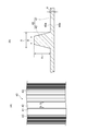
- FIG. 3 is a perspective view showing an example of the battery case. 4 is a cross-sectional view taken along line IV-IV in FIG.
- FIG. 5 is a perspective view showing an example of the electrode plate group.
- FIG. 6 is a front view showing an electrode plate (positive electrode plate or negative electrode plate).
- 7A is a cross-sectional view taken along the line VII-VII in FIG. 6 and shows a positive electrode plate
- FIG. 7B is a cross-sectional view taken along the line VII-VII in FIG. It is sectional drawing shown.
- FIG. 8B are front views showing an example of a current collector (a positive electrode current collector or a negative electrode current collector).
- FIG. 9 is a view showing a bag-shaped separator and electrodes accommodated in the bag-shaped separator.
- FIG. 10A is a view showing an example of the separator, and
- FIG. 10B is a cross-sectional view taken along the line Ib-Ib in FIG.
- FIG. 11 is a cross-sectional view showing an example of the arrangement of the separator and the electrode plate.
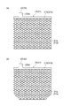
- FIG. 12 is a front view showing an example of the electrode plate group.
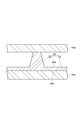
- FIG.13 (a) is a figure which shows the process of accommodating an electrode group in the area
- FIG.13 (b) is a figure which shows the state in which the electrode group was accommodated in the area
- the term “layer” includes a structure formed in a part in addition to a structure formed in the entire surface when observed as a plan view.
- a numerical range indicated by using “to” indicates a range including the numerical values described before and after “to” as the minimum value and the maximum value, respectively.
- the upper limit value or lower limit value of a numerical range of a certain step may be replaced with the upper limit value or lower limit value of the numerical range of another step.
- the upper limit value or the lower limit value of the numerical range may be replaced with the values shown in the examples. “A or B” only needs to include either A or B, and may include both.
- each component in the composition is the sum of the plurality of substances present in the composition unless there is a specific indication when there are a plurality of substances corresponding to each component in the composition.
- the liquid lead acid battery according to the present embodiment (hereinafter, also simply referred to as “lead acid battery”) is accommodated in a battery case divided into two or more regions by one or a plurality of partition walls, and two or more regions, respectively. And an electrode plate group including a plurality of positive electrode plates, a plurality of separators, and a plurality of negative electrode plates, and an electrolyte contained in the battery case. If the width of the region is X mm and the thickness of the electrode plate group is Y mm, X and Y satisfy the following conditional expression. -1.1 ⁇ XY ⁇ 1.2
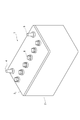
- FIG. 1 is a perspective view of a lead storage battery (liquid lead storage battery) according to this embodiment
- FIG. 2 is a view showing an internal structure of the lead storage battery 1.
- the lead storage battery 1 includes a battery case 2 in which an upper surface is opened and a plurality of electrode plate groups 11 are accommodated, and a lid 3 that closes the opening of the battery case 2.
- the lid 3 is made of, for example, polypropylene, and includes a positive electrode terminal 4, a negative electrode terminal 5, and a liquid port plug 6 that closes a liquid injection port provided in the lid 3.
- the battery case 2 contains an electrolyte (not shown).
- FIG. 3 is a perspective view showing the battery case. 4 is a cross-sectional view taken along line IV-IV in FIG.
- the inside of the battery case 2 is divided into six sections by five partition walls 51 to form six regions (cell chambers) 52. That is, the battery case 2 has five partition walls 51 and has six regions (cell chambers) 52 separated by the partition walls 51.
- Each region 52 is a space into which the electrode plate group 11 is inserted.
- a plurality of ribs (rib portions) extending in the height direction of the battery case 2 are formed on both side surfaces of the partition wall 51 and the pair of inner wall surfaces 50 facing the partition wall 51 of the battery case 2.
- the partition wall 51 may include a flat portion 54 and a plurality of ribs 53 extending in the height direction of the battery case 2 protruding from the flat portion 54.
- the rib 53 is suitable for the electrode plate group 11 inserted in the region 52 in the stacking direction of the electrode plate group 11 (the stacking direction of the positive electrode plate 12 and the negative electrode plate 13 when the electrode plate group 11 is stored in the battery case 2). It has a function to pressurize (compress).
- the height of the rib 53 may be set so that the width X of the region 52 has a predetermined value.
- the partition wall 51 may further include an inclined portion 55 that is provided on the entrance side of the region 52 and extends from the flat portion 54 to the rib portion 53.
- the battery case 2 is preferably a box having an open upper surface from the viewpoint of easy accommodation of the electrode plate group 11. In this case, the upper surface of the box is covered with the lid 3. Note that an adhesive, heat welding, laser welding, ultrasonic welding, or the like can be appropriately used for bonding the box and the lid 3.
- the shape of the battery case 2 is not particularly limited, but a rectangular shape is preferable so that an ineffective space is reduced when an electrode (a plate plate or the like) is accommodated.
- the material of the battery case 2 is not particularly limited, but needs to be resistant to an electrolytic solution (such as dilute sulfuric acid).
- Specific examples of the material of the battery case 2 include PP (polypropylene), PE (polyethylene), and ABS resin.
- PP is advantageous in terms of acid resistance and cost.
- ABS resin heat welding of the battery case 2 and the lid 3 is likely to be difficult, so that PP is advantageous in terms of workability.
- the battery case 2 is a box having an open upper surface
- the battery case 2 and the lid 3 may be made of the same material or different materials. From the viewpoint of preventing excessive stress, materials having the same thermal expansion coefficient are preferable.
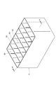
- FIG. 5 is a perspective view showing an example of the electrode plate group.
- the electrode plate group 11 includes a plurality of electrode plates (a plurality of positive electrode plates 12 and a plurality of negative electrode plates 13) and a plurality of separators.
- the positive electrode plate 12 and the negative electrode plate 13 constitute the electrode plate group 11 by being laminated via a separator.
- the electrode plate group 11 includes, for example, a positive electrode plate 12, a negative electrode plate 13, a bag-like separator 14, a positive electrode side strap 15, a negative electrode side strap 16, an inter-cell connection portion 17 or an electrode column 18. Yes.
- FIG. 6 is a front view showing an electrode plate (positive plate 12 or negative plate 13).
- 7 is a cross-sectional view taken along the line VII-VII in FIG. 6.
- FIG. 7 (a) illustrates a cross section of the positive electrode plate 12
- FIG. 7 (b) illustrates a cross section of the negative electrode plate 13.
- FIG. 8 is a front view showing a current collector (positive electrode current collector 21 or negative electrode current collector 31). 6 and 8, the reference numerals in parentheses indicate the configuration of the negative electrode plate 13.
- the electrode plates include, for example, an electrode material filling portion (a positive electrode material filling portion 24 and a negative electrode material filling portion 34) constituted by electrode materials (a positive electrode material 23 and a negative electrode material 33), and an electrode.
- Current collectors positive electrode current collector 21 and negative electrode current collector 31 that support the material filling portion.
- a portion filled with the electrode material becomes an electrode material filling portion (portion hatched in a sandy shape in FIG. 6).
- the current collectors (the positive electrode current collector 21 and the negative electrode current collector 31) constitute a conductive path for current to the electrode materials (the positive electrode material 23 and the negative electrode material 33).
- the current collector includes, for example, an electrode material support portion (a positive electrode material support portion 21a and a negative electrode material support portion 31a) that supports the electrode material, and an electrode material support.
- the upper frame part (upper peripheral part 21b of the positive electrode current collector and the upper peripheral part 31b of the negative electrode current collector) formed in a band shape on the upper side of the part, and the ear part (positive electrode ear part 22 and the upper peripheral part 31b of the negative electrode current collector) Negative electrode ear 32).
- the outer shape of the electrode material support portion is, for example, a rectangle (rectangle or square) and is formed in a lattice shape. As shown in FIG. 8B, the electrode material support portion may have a shape in which a lower corner is cut off.
- the ear portion is provided so as to protrude upward from the upper frame portion of the current collector.
- composition of the current collector examples include a lead-calcium-tin alloy, a lead-calcium alloy, and a lead-antimony alloy.
- a current collector can be obtained by forming these lead alloys in a lattice shape by a gravity casting method, an expanding method, a punching method, or the like. Note that the current collector shown in FIG. 8 is an expanded lattice.
- the surface of the negative electrode current collector 32 is preferably composed of a surface layer 32a containing Sn.
- the composition of the negative electrode current collector 31 other than the surface layer 32 a may be the same as that of the positive electrode current collector 21.
- the surface layer may mainly contain Pb in addition to Sn.
- the surface layer may contain a Sn alloy.
- the content of Sn is, for example, 4 parts by mass or more, 9 parts by mass or more, 30 parts by mass or more, or 50 parts by mass or more, based on the total mass of the surface layer, from the viewpoint of further suppressing the ear thinning phenomenon. May be. 100 mass parts may be sufficient from a viewpoint which can suppress the ear-warming phenomenon more, and a viewpoint on manufacture.
- the Sn content is 100 parts by mass, that is, when the surface layer 32a is made of Sn, the surface layer 32a may contain inevitable impurities in addition to Sn. Examples of such impurities include Ag, Al, As, Bi, Ca, Cd, Cu, Fe, Ni, Sb, and Zn.
- the whole negative electrode current collection part 32 is covered with the surface layer 32a, the location where the surface layer 32a is not provided may exist.
- the surface layer 32 a may be provided only on one main surface of the negative electrode current collector 32.
- the negative electrode current collector 31 having the surface layer 32a can be produced by the same method as the positive electrode current collector 21, except that the surface layer 32a is formed, for example.
- the method for producing the negative electrode current collector 31 may include, for example, a step of producing a current collector by a method similar to that of the positive electrode current collector 21, and a step of subsequently forming the surface layer 32a at a predetermined location. Alternatively, it may include a step of preparing an alloy plate in which the surface layer 32a is formed in advance, and a step of obtaining the negative electrode current collector 31 by processing the alloy plate.
- Examples of the method for forming the surface layer 32a include a rolling method and a hot dipping method.
- the rolling method is a method in which a material for forming the surface layer 32a (for example, a metal plate, an alloy plate, etc.) and a material for forming the surface layer 32a (for example, a sheet containing Sn) are superposed and rolled.
- the hot dipping method is a method in which plating is performed by immersing a portion where the surface layer 32a is to be formed in a melting tank in which a material (material containing Sn) for forming the surface layer 32a is melted.
- the rolling method is preferable among these methods.
- the method for forming the surface layer 32a by a rolling method may be, for example, the following method. First, Sn sheets for forming the surface layer 32a are superimposed on both surfaces of a plate-like lead alloy (base material), and then rolled with a rolling roller to produce a rolled sheet (a rolled sheet is produced). Process). Next, the rolled sheet is developed by an expanding machine while adjusting the position of the rolled sheet so that the surface layer 32a is formed in the region to be the negative electrode current collector 32 of the negative electrode current collector 31 (expanding method). Thereby, the negative electrode current collector 31 having the surface layer 32a is obtained.
- the thickness of the surface layer 32a is adjusted by adjusting the thickness of the alloy serving as the base material, the thickness of the sheet serving as the surface layer 32a, and / or the thickness of the sheet after rolling. It is easily adjustable.
- the thickness d of the surface layer 32a after rolling may be, for example, 10 to 60 ⁇ m from the viewpoint of manufacturing.
- the separator according to the present embodiment may be a separator made of at least one selected from glass, pulp, and synthetic resin, for example. Further, the separator according to the present embodiment may be a flexible separator. Among the separators, it is preferable to use a synthetic resin from the viewpoint that the short circuit can be further suppressed and that the electrode group can be easily compressed by having flexibility. Further, among the synthetic resins, polyolefin is particularly preferable.
- FIG. 9 is a view showing a bag-like separator 14 and an electrode plate (for example, a negative electrode plate 13) accommodated in the bag-like separator 14.
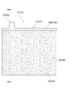
- FIG. 10A is a front view showing the separator 40 used for producing the bag-shaped separator 14, and
- FIG. 10B is a cross-sectional view of the separator 40.
- FIG. 11 is a cross-sectional view of the separator 40 and the electrode plates (the positive electrode plate 12 and the negative electrode plate 13).
- the separator 40 may be used as it is as the separator, but as shown in FIG. 9, the bag-shaped separator 14 is used so that at least one of the positive electrode plate 12 and the negative electrode plate 13 can be accommodated. It is preferable. For example, a mode in which one of the positive electrode plate 12 and the negative electrode plate 13 is accommodated in the bag-shaped separator 14 and is alternately stacked with the other of the positive electrode plate 12 and the negative electrode plate 13 is preferable.
- the bag-shaped separator 14 is applied to the positive electrode plate 12, the positive electrode plate 12 may pass through the separator due to the extension of the positive electrode current collector 21, so that the negative electrode plate 13 is accommodated in the bag-shaped separator 14.
- a separator has a convex-shaped rib and the base part which supports the said rib.
- the separator 40 includes a flat base portion 41, a plurality of convex (for example, linear) ribs 42, and mini-ribs 43.
- the base portion 41 supports the ribs 42 and the mini ribs 43.
- the ribs 42 are formed in plural (many) at the center in the width direction of the separator 40 so as to extend in the longitudinal direction of the separator 40.
- the plurality of ribs 42 are disposed substantially parallel to each other on the one surface 40 a of the separator 40.
- the interval between the ribs 42 is, for example, 3 to 15 mm.
- One end of the rib 42 in the height direction is integrated with the base portion 41, and the other end of the rib 42 in the height direction is in contact with one of the positive electrode plate 12 and the negative electrode plate 13 (see FIG. 11).
- the base portion 41 faces the electrode plate 44a in the height direction of the ribs 42.
- Ribs are not disposed on the other surface 40b of the separator 40, and the other surface 40b of the separator 40 faces or is in contact with the other electrode 44b (see FIG. 11) of the positive electrode plate 12 and the negative electrode plate 13.
- it is preferable that the other end in the height direction of the rib 42 is in contact with the positive electrode plate 12, and the other surface 40 b of the separator 40 is opposed to or in contact with the negative electrode plate 13.
- a plurality of (many) mini-ribs 43 are formed on both sides of the separator 40 in the width direction so as to extend in the longitudinal direction of the separator 40.
- the mini rib 43 has a function of improving the separator strength in order to prevent the corners of the electrodes from breaking through the separator when the lead storage battery 1 vibrates in the lateral direction.
- the height, width, and interval of the mini-ribs 43 are preferably smaller than the ribs 42.
- the cross-sectional shape of the mini-rib 43 may be the same as or different from the rib 42.
- the cross-sectional shape of the mini-rib 43 is preferably a semicircular shape. Further, the mini-rib 43 may not be formed in the separator 40.
- the upper limit of the thickness T of the base portion 41 is, for example, 0.25 mm from the viewpoint of obtaining excellent charge acceptance and discharge characteristics. When the thickness T is 0.25 mm or less, charge acceptance and discharge characteristics tend to be improved.
- the upper limit of the thickness T of the base portion 41 is preferably 0.2 mm and more preferably 0.15 mm from the viewpoint of obtaining further excellent charge acceptance and discharge characteristics.
- the lower limit of the thickness T of the base portion 41 is not particularly limited, but can be set to 0.05 mm or 0.1 mm from the viewpoint of excellent short circuit suppression effect.
- the upper limit of the height of the rib 42 (height in the facing direction of the base portion 41 and the electrode) H is preferably 1.25 mm, more preferably 1.0 mm, and 0.75 mm from the viewpoint of obtaining excellent charge acceptance. Further preferred.
- the lower limit of the height H of the rib 42 is, for example, 0.3 mm, and may be 0.4 mm or 0.5 mm from the viewpoint of suppressing oxidative deterioration at the positive electrode.
- the thickness of the separator where the ribs 42 are provided is, for example, 0.4 to 0.75 mm, and 0.4 to 0.7 mm. 0.4 to 0.65 mm, 0.4 to 0.6 mm, 0.5 to 0.75 mm, 0.55 to 0.75 mm, 0.6 to 0.75 mm, or 0.6 to 0.7 mm There may be.
- the lower limit of the ratio H / T of the height H of the rib 42 to the thickness T of the base portion 41 may be 2 or more from the viewpoint of excellent oxidation resistance of the separator.
- the ratio H / T is 2 or more, a portion that does not contact the electrode (for example, the positive electrode plate 12) can be sufficiently secured, so that it is presumed that the oxidation resistance of the separator is improved.
- the lower limit of the ratio H / T is preferably 2.4, more preferably 3, from the viewpoint of excellent oxidation resistance and productivity of the separator.
- the upper limit of the ratio H / T may be 6 from the viewpoint of excellent rib shape retention and the effect of suppressing a short circuit. If the ratio H / T is 6 or less, the distance between the positive electrode plate 12 and the negative electrode plate 13 is sufficient, and it is assumed that short-circuiting is suppressed. Further, when the ratio H / T is 6 or less, it is presumed that the battery characteristics such as charge acceptability are favorably maintained without damaging the ribs when the lead storage battery 1 is assembled.
- the upper limit of the ratio H / T is preferably 5, more preferably 4.5, and still more preferably 4, from the viewpoint of excellent short-circuit suppressing effect and excellent rib shape retention.
- the upper base width B (see FIG. 10B) of the rib 42 is preferably 0.1 to 2 mm, more preferably 0.2 to 1 mm, from the viewpoint of excellent shape retention and oxidation resistance of the rib. More preferably, it is 0.2 to 0.8 mm.
- the bottom width A of the rib 42 is preferably 0.2 to 4 mm, more preferably 0.3 to 2 mm, and still more preferably 0.4 to 1 mm, from the viewpoint of excellent rib shape retention.
- the ratio (B / A) between the upper base width B and the lower base width A is preferably 0.1 to 1, more preferably 0.2 to 0.8, from the viewpoint of excellent rib shape retention. More preferably, 0.6 is used.
- the separator 40 used for producing the bag-shaped separator 14 is formed in a long sheet shape, for example.
- the bag-like separator 14 may be produced by cutting the separator 40 into an appropriate length.
- the method for accommodating the electrode plate (for example, the negative electrode plate 13) in the bag-shaped separator 14 may be, for example, the following method.
- the separator 40 cut to an appropriate length is folded into a U-shape or a V-shape at approximately the center in the longitudinal direction on the surface where the ribs are not provided to obtain a laminated sheet. Subsequently, both side portions of the laminated sheet are mechanically sealed, pressure-bonded, or thermally welded (for example, reference numeral 45 in FIG.
- a separator made of polyolefin (a microporous polyethylene sheet) made of a microporous sheet can be used.
- the separator 40 may be a microporous polyethylene sheet; a glass fiber and acid-resistant paper bonded together.
- the microporous polyethylene sheet is not used alone, but from at least one fiber selected from the group consisting of fibers composed of materials such as glass fiber, polyolefin fiber and pulp. It is preferable to use a nonwoven fabric (a separator made of a nonwoven fabric) and a microporous polyethylene sheet in combination.
- the microporous polyethylene sheet and the nonwoven fabric may be used in an overlapping manner so that the surface of the separator facing the negative electrode plate 13 is constituted by the nonwoven fabric. That is, the negative electrode plate 13 and the nonwoven fabric in the lead storage battery may be brought into contact with each other.
- the factor which is further excellent in liquid reduction performance by using a nonwoven fabric is not clear, it is guessed as follows.
- the non-woven fabric By using the non-woven fabric, the gas generated by electrolysis is trapped in the non-woven fabric, and the gas is present at the interface between the electrode material and the electrolytic solution. As a result, the area of the interface between the electrode material and the electrolytic solution decreases, and the overvoltage for gas generation increases. This is presumed to be further excellent in the liquid reduction performance.
- the above-mentioned nonwoven fabric may appropriately contain inorganic oxide powder such as silica. Moreover, you may use a nonwoven fabric alone as a separator, without combining with a microporous polyethylene sheet.
- the clearance (XY) in the liquid lead storage battery according to this embodiment is, for example, ⁇ 1.1 to 1.2.
- the clearance (XY) is preferably ⁇ 1.0 or more, more preferably ⁇ 0.6 or more, from the viewpoint of sufficiently suppressing the decrease in the electrolyte and further suppressing the short circuit.
- the clearance (XY) is preferably 1.0 or less, more preferably 0.0 or less, and still more preferably less than 0.0, from the viewpoint of sufficiently suppressing the decrease in the electrolytic solution. From these viewpoints, the clearance (XY) is preferably ⁇ 1.0 to 1.0, more preferably ⁇ 0.6 to 0.0, and still more preferably ⁇ 0.6 to less than ⁇ 0.0.
- the widths of the plurality of areas may be the same or different.
- the width X of the region 52 can be adjusted by the height of the rib 53 or the like.
- the width X of the region is the shortest distance between the facing partition walls 51 or the inner wall surface 50 of the battery case 2 facing the partition wall 51 when the partition wall 51 does not have the ribs 53. Is defined as the shortest distance (hereinafter collectively referred to as “distance between walls”).
- the width X of the region is defined as a value obtained by subtracting the highest rib height Ha from the inter-wall distance Xa (see FIG. 4). ).
- the width X of the region is [distance between walls Xa] ⁇ (2 ⁇ [rib height Ha]).
- the thickness Y of the plurality of electrode plate groups may be the same or different.
- the thickness Y of the electrode plate group 11 can be adjusted by the thickness of the current collector, the thickness of the electrode plate, the thickness of the separator, the distance between the electrode plates, and the like.
- the thickness Y of the electrode plate group means the thickness of the electrode plate group in a state where no compressive force is applied.
- the thickness Y of the electrode plate group is higher than the boundary between the electrode material filling portion of the outermost electrode plate of the electrode plate group and the upper frame portion (upper peripheral portion) of the current collector included in the electrode plate.
- a range r of ⁇ 3 mm one point is measured at the center p1 in the width direction of the electrode plate group, one point at an arbitrary position p2 on the right side of the center, and one point at an arbitrary position p3 on the left side of the center. It is defined as the average value of the thickness of the electrode plate group (see FIG. 12).
- FIGS. 12 the average value of the thickness of the electrode plate group
- the rib 42 of the separator is usually the partition wall 51 of the battery case 2 (or the rib 53 included in the partition wall 51). Therefore, the height H of the rib 42 of the separator is not included in the thickness of the electrode plate group. That is, in the case where the separator is disposed on the outermost side of the electrode plate group, the thickness of the electrode plate group is measured at the position of the base portion 41 of the separator.
- the thickness Y of the electrode group in the liquid lead-acid battery after chemical conversion is, for example, sufficient that the electrode group after chemical conversion is taken out and washed with water for 1 hour, and the electrode group from which sulfuric acid is removed is sufficient in a system in which oxygen is not present. It can be measured after drying.
- the electrode plate group 11 may have a structure spreading downward. That is, when the thickness at the lower end of the electrode plate group 11 is Ya, Ya may be a value smaller than Y.
- the distance between the adjacent positive electrode plate 12 and negative electrode plate 13 (distance between the electrode plates) in the electrode plate group in a state in which no compressive force is applied to the electrode plate group 11 is a viewpoint that can sufficiently suppress the decrease in the electrolyte, and From the viewpoint of suppressing a short circuit, it is preferably 0.4 mm or more, more preferably 0.5 mm or more, and further preferably 0.55 mm or more.
- the distance between the electrode plates is preferably 7.5 mm or less, more preferably 0.7 mm or less, and still more preferably 0.65 mm or less, from the viewpoint of sufficiently suppressing the decrease in the electrolyte. Still more preferably, it is 0.6 mm or less.
- the distance between the electrode plates is preferably 0.4 to 7.5 mm, preferably 0.4 to 0.75 mm, and more preferably 0.5 to 0.7 mm. 0.55 to 0.65 mm is more preferable, and 0.55 to 0.6 mm is even more preferable.
- the separators are separated at the position of about 8 mm from the upper end 46 to the lower end 47 side.
- the thickness can be measured, and the average value of the measured values can be used as the distance between the electrode plates.
- the thickness of the separator is the sum of the thickness T of the base portion and the height H of the rib.
- two ribs (42a and 42b in FIG. 9) arranged on the outermost side in the width direction and ribs (42c in FIG.
- the average value of the thicknesses measured at a total of three points is taken as the thickness of the separator.
- the electrode plate group measured at a total of three points one point at the center in the width direction of the separator, one point at an arbitrary position to the right of the center, and one point at an arbitrary position to the left of the center.
- the average value of thickness be the thickness of a separator.
- a separator is bag shape, a separator is expand
- the distance between the electrode plates in a state in which no compressive force is applied to the electrode plate group 11 is taken out of the battery after chemical conversion, washed with water for 1 hour, and the electrolytic solution (
- the electrode plate group from which sulfuric acid has been removed can be measured by the above-mentioned method after sufficiently drying in an oxygen-free system.
- the electrode material which comprises the electrode material filling part of an electrode plate (the positive electrode plate 12 and the negative electrode plate 13) is demonstrated.
- the electrode material contains, for example, an electrode active material.
- an electrode material means the electrode material after chemical conversion (for example, a full charge state). In the non-chemical conversion stage, the material corresponding to the electrode material contains a substance that becomes the electrode material by chemical conversion.
- the positive electrode material 23 contains, for example, a positive electrode active material.
- the positive electrode active material is obtained by, for example, aging and drying a positive electrode material paste containing a material (a raw material of the positive electrode active material) that becomes a positive electrode active material by chemical conversion, and then obtaining an unformed positive electrode active material. It can be obtained by forming.
- the positive electrode active material preferably contains ⁇ -lead dioxide ( ⁇ -PbO 2 ), and may further contain ⁇ -lead dioxide ( ⁇ -PbO 2 ).
- ⁇ -PbO 2 ⁇ -lead dioxide
- the lead powder for example, lead powder manufactured by a ball mill type lead powder manufacturing machine or a barton pot type lead powder manufacturing machine (in the ball mill type lead powder manufacturing machine, a mixture of powder of main component PbO and scale-like metal lead) ).
- Red lead as a raw material of the positive electrode active material (Pb 3 O 4) may be used.
- the unformed positive electrode material preferably contains an unformed positive electrode active material containing tribasic lead sulfate as a main component.
- the positive electrode material 23 may further contain an additive.
- the additive include carbonaceous materials (carbonaceous conductive materials), reinforcing short fibers, and the like.
- the carbonaceous material include carbon black and graphite.
- Examples of carbon black include furnace black (Ketjen black, etc.), channel black, acetylene black, thermal black, and the like.
- Examples of the reinforcing short fibers include acrylic fibers, polyethylene fibers, polypropylene fibers, polyethylene terephthalate fibers, and carbon fibers.
- the specific surface area of the upper limit of the positive electrode material is not particularly limited, from the viewpoint of excellent practical point of view and utilization, preferably 15 m 2 / g, more preferably 12m 2 / g, 7m 2 / g is more preferable.
- the specific surface area of the positive electrode material 23 here means the specific surface area of the positive electrode material 23 (what was formed).
- the specific surface area of the positive electrode material 23 is, for example, a method of adjusting the amount of sulfuric acid and water added when preparing the positive electrode material paste, a method of refining the raw material of the active material in the unformed stage, and a method of changing the chemical conversion conditions Etc. can be adjusted.
- the specific surface area of the positive electrode material 23 can be measured by, for example, the BET method.
- the BET method is a method in which an inert gas (for example, nitrogen gas) having a known molecular size is adsorbed on the surface of a measurement sample, and the surface area is obtained from the adsorption amount and the area occupied by the inert gas. This is a general method for measuring the surface area.
- the negative electrode material 33 contains, for example, a negative electrode active material.
- the negative electrode active material is obtained by, for example, aging and drying a negative electrode material paste containing a material (a raw material of the negative electrode active material) that becomes a negative electrode active material by chemical conversion, and then obtaining an unformed negative electrode active material. It can be obtained by forming.
- Examples of the negative electrode active material include spongy lead. Spongy lead tends to react with sulfuric acid in the electrolyte and gradually change to lead sulfate (PbSO 4 ).
- Examples of the raw material for the negative electrode active material include lead powder.
- the lead powder for example, lead powder manufactured by a ball mill type lead powder manufacturing machine or a barton pot type lead powder manufacturing machine (in the ball mill type lead powder manufacturing machine, a mixture of powder of main component PbO and scale-like metal lead) ).
- the negative electrode material paste is composed of, for example, basic lead sulfate, metallic lead, and a lower oxide.
- the negative electrode material 33 may further contain an additive.
- an additive a resin having at least one selected from the group consisting of a sulfone group (sulfonic acid group, sulfo group) and a sulfonic acid group (a group in which a hydrogen atom of the sulfone group is substituted with an alkali metal) (sulfone group and And / or a resin having a sulfonate group), barium sulfate, a carbonaceous material (carbonaceous conductive material), a reinforcing short fiber, and the like.
- the negative electrode material 33 preferably contains a resin having a sulfone group and / or a sulfonate group.
- a carbon fiber is mentioned as an example of the short fiber for reinforcement, you may add this to a negative electrode material as a carbonaceous material (carbonaceous conductive material).
- resin having a sulfone group and / or a sulfonate group examples include bisphenol resins having a sulfone group and / or a sulfonate group (hereinafter simply referred to as “bisphenol resins”), lignin sulfonic acid, and lignin sulfonate. It is done. Among these, from the viewpoint of further improving the charge acceptance, a bisphenol-based resin is preferable.
- a bisphenol-based resin that is a condensate of at least one selected with at least one selected from the group consisting of formaldehyde and a formaldehyde derivative is more preferable.
- the bisphenol-based resin preferably has at least one of a structural unit represented by the following general formula (II) and a structural unit represented by the following general formula (III).
- X 2 represents a divalent group
- a 2 represents an alkylene group having 1 to 4 carbon atoms or an arylene group
- R 21 , R 23 and R 24 are each independently Represents an alkali metal or hydrogen atom
- R 22 represents a methylol group (—CH 2 OH)
- n21 represents an integer of 1 to 150
- n22 represents an integer of 1 to 3
- n23 represents 0 Or 1 is shown.
- the hydrogen atom directly bonded to the carbon atom constituting the benzene ring may be substituted with an alkyl group having 1 to 5 carbon atoms.
- X 3 represents a divalent group
- a 3 represents an alkylene group having 1 to 4 carbon atoms or an arylene group
- R 31 , R 33 and R 34 are each independently selected.
- R 32 represents a methylol group (—CH 2 OH)
- n31 represents an integer of 1 to 150
- n32 represents an integer of 1 to 3
- n33 represents 0 Or 1 is shown.
- the hydrogen atom directly bonded to the carbon atom constituting the benzene ring may be substituted with an alkyl group having 1 to 5 carbon atoms.
- the ratio of the structural unit represented by the formula (II) and the structural unit represented by the formula (III) is not particularly limited, and may vary depending on synthesis conditions and the like.
- a resin having only one of the structural unit represented by the formula (II) and the structural unit represented by the formula (III) may be used.
- Examples of X 2 and X 3 include alkylidene groups (methylidene groups, ethylidene groups, isopropylidene groups, sec-butylidene groups, etc.), cycloalkylidene groups (cyclohexylidene groups, etc.), phenylalkylidene groups (diphenylmethylidene groups).
- alkylidene groups methylidene groups, ethylidene groups, isopropylidene groups, sec-butylidene groups, etc.
- cycloalkylidene groups cyclohexylidene groups, etc.
- phenylalkylidene groups diphenylmethylidene groups.
- a phenylsulfonyl group, and the like; a sulfonyl group, and the isopropylidene group (—C (CH 3 ) 2 —) is preferable from the viewpoint of further excellent charge acceptance, and from the
- X 2 and X 3 may be substituted with a halogen atom such as a fluorine atom.
- a halogen atom such as a fluorine atom.
- the hydrocarbon ring may be substituted with an alkyl group or the like.
- Examples of A 2 and A 3 include alkylene groups having 1 to 4 carbon atoms such as a methylene group, an ethylene group, a propylene group, and a butylene group; and divalent arylene groups such as a phenylene group and a naphthylene group.
- the arylene group may be substituted with an alkyl group or the like.
- Examples of the alkali metal for R 21 , R 23 , R 24 , R 31 , R 33 and R 34 include sodium and potassium.
- n21 and n31 are preferably 1 to 150, more preferably 10 to 150, from the viewpoint of further excellent cycle characteristics and solubility in a solvent.
- n22 and n32 are preferably 1 or 2, and more preferably 1, from the viewpoint that the cycle characteristics, discharge characteristics, and charge acceptability are easily improved in a balanced manner.
- n23 and n33 change with manufacturing conditions, 0 is preferable from a viewpoint which is further excellent in cycling characteristics and the storage stability of bisphenol-type resin.
- the weight average molecular weight of a resin having a sulfonic group and / or a sulfonic acid group suppresses the elution of a resin having a sulfonic group and / or a sulfonic acid group from an electrode to an electrolytic solution in a lead storage battery.
- the weight average molecular weight of the resin having a sulfone group and / or a sulfonate group is 200000 or less from the viewpoint that the cycle characteristics are easily improved by suppressing the adsorptivity to the electrode active material and the dispersibility. Is preferable, 150,000 or less is more preferable, and 100,000 or less is still more preferable.
- the weight average molecular weight of the resin having a sulfone group and / or a sulfonate group can be measured, for example, by gel permeation chromatography (hereinafter referred to as “GPC”) under the following conditions.
- GPC gel permeation chromatography
- Carbonaceous material carbonaceous conductive material
- a phenomenon called sulfation in which lead sulfate, which is an insulator generated in a negative electrode material during discharge, becomes coarser as charge and discharge are repeated, is a phenomenon called sulfation. It occurs early. When sulfation occurs, charge acceptability and discharge performance are significantly reduced.
- the coarsening of lead sulfate is suppressed, the lead sulfate is kept in a fine state, and the concentration of lead ions dissolved from the lead sulfate decreases in the electrolyte. The effect which suppresses this and maintains a state with high charge acceptance is acquired.
- the carbonaceous material is preferably selected from the material group consisting of graphite, carbon black, activated carbon, carbon fiber, and carbon nanotube.
- graphite is selected, and more preferably, scaly graphite is selected.
- the average primary particle diameter of the flaky graphite is preferably larger than 100 ⁇ m.
- flaky graphite refers to that described in JISM8601 (2005).
- the electrical resistivity of the flake graphite is 0.02 ⁇ ⁇ cm or less, which is an order of magnitude smaller than the electrical resistivity (around 0.1 ⁇ ⁇ cm) of carbon blacks such as acetylene black. Therefore, by using scale-like graphite instead of carbon blacks used in conventional lead-acid batteries, the electrical resistance of the negative electrode active material can be lowered and the charge acceptance can be further improved.
- the average primary particle diameter of the scaly graphite is obtained according to the laser diffraction / scattering method described in JISM8511 (2005).
- a laser diffraction / scattering type particle size distribution measuring device Nikkiso Co., Ltd .: Microtrac 9220FRA
- a commercially available surfactant polyoxyethylene octylphenyl ether for example, Roche Diagnostics Co., Ltd .: Triton
- An appropriate amount of a scaly graphite sample is put into an aqueous solution containing 0.5 vol% of X-100), 40 W ultrasonic waves are irradiated for 180 seconds while stirring, and then measurement is performed.
- the obtained average particle diameter (median diameter: D50) is defined as the average primary particle diameter.
- the content of the carbonaceous material is preferably in the range of 0.1 to 3 parts by mass with respect to 100 parts by mass of the fully charged negative electrode active material (sponge metal lead).
- reinforcing short fibers examples include acrylic fibers, polyethylene fibers, polypropylene fibers, polyethylene terephthalate fibers, and carbon fibers.
- the mass ratio of the positive electrode material to the negative electrode material (positive electrode material / negative electrode material) is preferably 0.9 or more, more preferably 1 or more, from the viewpoint that sufficient battery capacity is easily obtained and high charge acceptance is easily obtained. 1.05 or more is still more preferable.
- the mass ratio of the positive electrode material to the negative electrode material is preferably 1.6 or less, more preferably 1.5 or less, and even more preferably 1.4 or less, from the viewpoint that a sufficient battery capacity is easily obtained.
- the mass ratio of the positive electrode material to the negative electrode material may be 1.3 or less.
- the mass ratio of the positive electrode material to the negative electrode material is preferably 0.9 to 1.6, more preferably 1 to 1.5, from the viewpoint that a sufficient battery capacity is easily obtained and high charge acceptance is easily obtained. .05 to 1.4 is more preferable.
- the mass ratio of the positive electrode material to the negative electrode material may be 1.05 to 1.3.
- the said mass ratio of the positive electrode material with respect to a negative electrode material is a mass ratio of the negative electrode material and positive electrode material after chemical conversion.
- the electrolytic solution contains, for example, sulfuric acid.
- the electrolytic solution may contain sodium ions and / or aluminum ions.
- the electrolytic solution preferably contains aluminum ions from the viewpoint of further excellent liquid reduction performance and the viewpoint of suppressing a short circuit during overdischarge.
- the reason why the electrolytic solution contains aluminum ions can suppress a short circuit during overdischarge is presumed to be because aluminum hydroxide tends to precipitate in the separator, particularly the surface layer portion, and lead precipitation is suppressed.
- the content of aluminum ions in the electrolytic solution is from the viewpoint that the effect of improving the liquid reduction performance becomes remarkable.
- concentration of aluminum ions is from the viewpoint that the effect of improving the liquid reduction performance becomes remarkable.
- 0.001 mol / L or more is preferable with respect to the amount, 0.03 mol / L or more is more preferable, and 0.06 mol / L or more is still more preferable.
- the concentration of aluminum ions is preferably 0.2 mol / L or less with respect to the amount of the electrolytic solution from the viewpoint that the effect of improving the liquid reduction performance becomes remarkable.
- the concentration of aluminum ions is preferably 0.001 to 0.2 mol / L, more preferably 0.03 to 0.2 mol / L, and still more preferably 0.06 to 0.2 mol / L.
- the aluminum ion concentration of the electrolytic solution can be measured by, for example, ICP emission spectroscopy (high frequency inductively coupled plasma emission spectroscopy).
- the electrolytic solution containing aluminum ions can be obtained, for example, by mixing sulfuric acid and aluminum sulfate (for example, aluminum sulfate powder).
- Aluminum sulfate dissolved in the electrolytic solution can be added as an anhydride or a hydrate.
- the specific gravity of the electrolytic solution after chemical conversion may be in the following range.
- the specific gravity of the electrolytic solution is preferably, for example, 1.25 or more, more preferably 1.28 or more, from the viewpoint of suppressing osmotic short-circuiting or freezing and being excellent in discharge characteristics (for example, excellent in low-temperature high-rate discharge performance). 1.285 or more are still more preferable, and 1.29 or more are especially preferable.
- the specific gravity of the electrolytic solution is preferably 1.33 or less, more preferably 1.32 or less, still more preferably 1.315 or less, and 1.31 from the viewpoint of improving charge acceptability and further improving ISS cycle characteristics.
- the value of the specific gravity of the electrolytic solution can be measured by, for example, a floating hydrometer or a digital hydrometer manufactured by Kyoto Electronics Industry Co., Ltd.
- the method for manufacturing a liquid lead-acid battery includes a step of preparing a battery case 2 divided into two or more regions 52 by one or a plurality of partition walls 51, a plurality of positive plates 12 and a plurality of separators.
- the compressing force in the thickness direction of the electrode plate group 11 is applied to the electrode plate group 11 from the partition wall 51.
- the electrode plate group is pushed into 52.
- the positive electrode plate 12 and the negative electrode plate 13 in the step of preparing two or more electrode plate groups 11 are an unformed positive electrode plate and negative electrode plate.
- the step of preparing two or more electrode plate groups 11 was obtained by, for example, an electrode plate manufacturing step for obtaining an unformed electrode plate (an unformed positive plate and an unformed negative plate) and an electrode plate manufacturing step.
- an electrode plate manufacturing step for obtaining an unformed electrode plate (an unformed positive plate and an unformed negative plate) and an electrode plate manufacturing step.
- an electrode material paste (a positive electrode material paste and a negative electrode material paste) is filled in a current collector (for example, a current collector grid such as a cast grid, an expanded grid, etc.), and then aged and dried. By performing this, an unformed electrode plate is obtained.
- the positive electrode material paste contains, for example, a raw material (lead powder or the like) of the positive electrode active material, and may further contain other additives.
- the negative electrode material paste contains a raw material (lead powder or the like) of the negative electrode active material, and may further contain other additives (for example, a dispersant).
- the negative electrode material paste preferably contains a resin having a sulfone group and / or a sulfonate group (such as a bisphenol resin) as a dispersant.
- the positive electrode material paste can be obtained, for example, by the following method. First, an additive (such as reinforcing short fibers) and water are added to the raw material of the positive electrode active material. Next, after adding dilute sulfuric acid, the mixture is kneaded to obtain a positive electrode material paste. In producing the positive electrode material paste, lead (Pb 3 O 4 ) may be used as a raw material for the positive electrode active material from the viewpoint of shortening the chemical formation time. After filling this positive electrode material paste into the positive electrode current collector 21, aging and drying are performed to obtain an unformed positive electrode plate.
- an additive such as reinforcing short fibers
- water water
- dilute sulfuric acid the mixture is kneaded to obtain a positive electrode material paste.
- lead (Pb 3 O 4 ) may be used as a raw material for the positive electrode active material from the viewpoint of shortening the chemical formation time. After filling this positive electrode material paste into the positive electrode current collector 21, aging and drying are performed to obtain an unformed positive electrode plate
- the blending amount of the reinforcing short fibers is preferably 0.005 to 0.3% by mass based on the total mass of the positive electrode active material (lead powder, etc.) 0.05 to 0.3% by mass is more preferable.
- aging conditions for obtaining an unformed positive electrode plate 15 to 60 hours are preferable in an atmosphere of a temperature of 35 to 85 ° C. and a humidity of 50 to 98 RH%.
- the drying conditions are preferably 45 to 80 ° C. and 15 to 30 hours.
- the negative electrode material paste can be obtained, for example, by the following method. First, an additive (a resin having a sulfone group and / or a sulfonate group, a reinforcing short fiber, barium sulfate, etc.) is added to the raw material of the negative electrode active material and dry mixed to obtain a mixture. And a negative electrode material paste is obtained by adding and knead
- a negative electrode current collector 31 for example, a current collector grid such as a cast grid or an expanded grid
- the amount of each component is preferably in the following range.
- the amount of the resin having a sulfone group and / or a sulfonate group is preferably 0.01 to 2.0% by mass in terms of resin solid content based on the total mass of the raw material of the negative electrode active material (such as lead powder). 0.05 to 1.0 mass% is more preferable, 0.1 to 0.5 mass% is still more preferable, and 0.1 to 0.3 mass% is particularly preferable.
- the blending amount of the carbonaceous material is preferably from 0.1 to 3% by mass, more preferably from 0.2 to 1.4% by mass, based on the total mass of the negative electrode active material (such as lead powder).
- the blending amount of the reinforcing short fibers is preferably 0.05 to 0.15% by mass based on the total mass of the raw material of the negative electrode active material (lead powder or the like).
- the compounding amount of barium sulfate is preferably 0.01 to 2.0% by mass, more preferably 0.01 to 1.0% by mass, based on the total mass of the negative electrode active material (lead powder, etc.).
- aging conditions for obtaining an unformed negative electrode plate 15 to 30 hours are preferable in an atmosphere of a temperature of 45 to 65 ° C. and a humidity of 70 to 98 RH%.
- the drying conditions are preferably 45 to 60 ° C. and 15 to 30 hours.
- the electrode plate group 11 is pushed into the region 52 of the battery case 2 as shown in FIG.
- the electrode plate group 11 is accommodated in the battery case 2 while applying the compressive force from the partition wall 51 to the electrode plate group 11. Thereby, an unformed battery is produced.
- the surface facing the partition 51 is the inner wall surface 50 of the battery case 2
- a compressive force in the thickness direction of the electrode plate group 11 is applied to the electrode plate group 11 from the partition wall 51 and the inner wall surface 50 of the battery case 2. .
- the clearance (XY) is preferably ⁇ 1.1 or more, and is ⁇ 1.0 or more. More preferably, it is more preferably ⁇ 0.6 or more. Further, from the viewpoint of easily setting the distance between the electrode plates, the clearance (XY) is preferably 1.2 or less, more preferably 1.0 or less, and 0.0 or less. Is more preferable, and it is particularly preferable to set it to less than 0.0. From these viewpoints, the clearance (XY) is preferably ⁇ 1.1 to 1.2, more preferably ⁇ 1.0 to 1.0, and ⁇ 0.6 to 0.0. More preferably, it is more preferably ⁇ 0.6 or more and less than 0.0.
- the electrode plate group 11 when the clearance (XY) is 1.16 or more, the electrode plate group 11 is not pushed in, and the electrode plate 11 is moved by its own weight in the region 52 of the battery case 2. If the clearance (XY) is smaller than 1.16, pressure F is applied to the electrode plate group 11 and the electrode plate group 11 is applied to the region 52 of the battery case 2. It is necessary to push in. Even when the clearance (XY) is a positive value, the reason why it is necessary to push the electrode plate group 11 into the region 52 of the battery case 2 is not clear, but as shown in FIG. In addition, it is assumed that the electrode plate group 11 has a structure that spreads downward.
- a compressive force is applied in the thickness direction of the electrode plate group 11 in accordance with the clearance. Therefore, by applying a pressure F above the electrode plate group 11, the region 52 of the battery case 2 is applied. It is necessary to push in the electrode plate group 11.
- the electrolytic solution is supplied (injected) into the battery case 2 of the unformed battery obtained by the step of housing the electrode plate group 11 in the region 52 of the battery case 2. .
- the manufacturing method according to the present embodiment may further include a step of forming an unformed battery after supplying the electrolytic solution.
- the step may be, for example, a step of forming a battery case by supplying a direct current and then supplying a electrolytic solution.
- the specific gravity of the electrolytic solution may be adjusted to an appropriate specific gravity. Thereby, the formed chemical liquid lead acid battery is obtained.
- Chemical conversion conditions and specific gravity of sulfuric acid can be adjusted according to the properties of the electrode active material. Further, the chemical conversion treatment is not limited to being performed after obtaining the non-chemical conversion battery, and may be performed after aging and drying in the electrode manufacturing process (tank chemical conversion).
- Example 1 ⁇ Production of lead acid battery> [Preparation of battery case]
- a battery case (inner thickness direction length: 3.5 cm) having a box body with an open upper surface and having an interior divided into six regions by partition walls was prepared.
- the partition wall and the inner wall surface of the battery case facing the partition wall are a flat part, a plurality of rib parts protruding from the flat part and extending in the height direction of the battery case, and provided on the entrance side of the region.
- the height of the rib was 1.4 mm.
- the width X (unit: mm) of each region was 32.2.
- the width X of the region is measured at a height of ⁇ 3 mm from the boundary between the upper peripheral edge of the electrode plate 11 located on the outermost side of the electrode plate group 11 accommodated in the battery case and the electrode material filling portion. did.
- Lead powder was used as a raw material for the negative electrode active material. 0.2% by mass of bisphenol-based resin (converted to solid content, manufactured by Nippon Paper Industries Co., Ltd., trade name: Vispaz P215), 0.1% by mass of reinforcing short fibers (acrylic fibers), and 1.0% by mass of barium sulfate % And a carbonaceous material (flaky graphite, average particle diameter (median diameter: D50): 180 ⁇ m) was added to the lead powder and then dry-mixed (the blending amount is negative electrode The blending amount is based on the total mass of the active material).
- the weight average molecular weight of the bisphenol-based resin was 53900 as measured by GPC under the conditions described above.
- the particle size of the scaly graphite was determined based on the laser diffraction / scattering method described in JISM8511 (2005).
- 10% by mass of water a blending amount based on the total mass of the raw material of the negative electrode active material
- dilute sulfuric acid specific gravity 1.280
- 9.5% by mass was added and kneaded little by little to prepare a negative electrode material paste.
- the negative electrode material paste was filled in an expanded lattice (current collector) produced by subjecting a rolled sheet made of a lead alloy to an expanding process.
- the current collector filled with the negative electrode material paste was aged in an atmosphere of a temperature of 50 ° C. and a humidity of 98% for 24 hours. Thereafter, it was dried to obtain an unformed negative electrode plate.
- a separator having a predetermined length made of a microporous sheet and having a plurality of linear ribs on one side (made of polyethylene, base portion thickness T: 0.2 mm, rib height H: 0.55 mm) was prepared and bent into a U-shape at approximately the center in the longitudinal direction of the surface on which the ribs of the separator were not provided, to obtain a laminated sheet. Subsequently, both side portions of the laminated sheet were mechanically sealed to obtain a bag-shaped separator.
- Electrode group An unchemically formed negative electrode plate was placed in a bag-shaped separator. Eight bag-like separators containing unformed negative plates and seven unformed positive plates were alternately laminated. Subsequently, the ears of the same polarity electrode plates were welded together by a cast on strap (COS) method to produce an electrode plate group.
- the strap portion was made of a Pb—Sb alloy, and the Sb content was 2.9% by mass with respect to the mass of the strap portion.
- the thickness Y (unit: mm) of the electrode plate group was 31.2.
- An electrolyte solution was prepared by adding sodium sulfate to dilute sulfuric acid so that the sodium ion concentration in the electrolyte solution after chemical conversion was 0.1 mol / L.
- the electrolyte solution had a specific gravity such that the specific gravity of the electrolyte solution after chemical conversion was 1.290.
- the electrode plate group was accommodated by being pushed into the battery case region, and a 12V battery (corresponding to D23 size defined in JIS D 5301) was assembled.
- the electrolytic solution was poured into this battery, and then formed in a 35 ° C. water bath at a current of 18.6 A for 18 hours to obtain a liquid lead acid battery.
- Various physical property values measured after chemical conversion are shown below.
- the average particle diameter of the positive electrode active material was 0.8 ⁇ m.
- the specific surface area of the positive electrode material was 6 m 2 / g.
- the average particle diameter of the negative electrode active material was 1.2 ⁇ m.
- the specific surface area of the negative electrode material was 1.0 m 2 / g.
- the mass ratio of the positive electrode material to the negative electrode material was 1.4. Moreover, the specific gravity of the electrolyte solution after chemical conversion was 1.290.
- the electrode plate group thickness Y (unit: mm) was 31.2. Since the width X of the battery case area was 32.2, the clearance (XY) was 1.0.
- the electrode plate group thickness Y (unit: mm) after chemical conversion is determined by taking out the electrode plate group from the battery after chemical conversion and washing it with water for 1 hour. It was measured after sufficiently drying in a system in which no water was present.
- the distance between the electrode plates in the electrode plate group taken out from the formed battery was measured by the following method. First, the electrode plate group was taken out from the formed battery and washed with water for 1 hour, and the electrode plate group from which the electrolyte solution was removed was sufficiently dried in a system without oxygen. Subsequently, all the separators were extracted from the dried electrode plate group. About all the separators extracted, the thickness of the separator was measured at a location of about 8 mm from the upper end to the lower end side of the separator, and the average value of the measured values was defined as the distance between the electrode plates.
- the thickness of the separator is measured on a total of three points on the two ribs arranged on the outermost side in the width direction and on the rib arranged on the midpoint among the plurality of formed ribs. The average value of the measured thickness was taken as the thickness of the separator. The distance between the electrode plates in the electrode plate group taken out from the formed battery was 0.75 mm.
- Example 2 A liquid lead acid battery was produced in the same manner as in Example 1 except that a battery case having a region width X (unit: mm) of 30.9 was used.
- the clearance (XY) after the formation was ⁇ 0.3, and the distance between the electrode plates in the electrode plate group taken out from the formed battery was 0.75 mm.
- Example 3 A liquid lead-acid battery was produced in the same manner as in Example 1 except that a battery case having a region width X (unit: mm) of 30.1 was used.
- the clearance (XY) after the formation was ⁇ 1.1, and the distance between the electrode plates in the electrode plate group taken out from the formed battery was 0.75 mm.
- Example 4 Example except that a battery case having a region width X (unit: mm) of 30.1 was used and a bag-shaped separator produced using a separator having a rib height of 0.4 mm was used.
- a liquid lead-acid battery was produced.
- the thickness Y (unit: mm) of the electrode plate group after the formation is 29.1
- the clearance (XY) after the formation is 1.0
- the electrode in the electrode plate group taken out from the battery after the formation is 1.0
- the distance between the plates was 0.6 mm.
- Example 5 Example except that a battery case having a region width X (unit: mm) of 27.3 and a bag-shaped separator produced using a separator having a rib height of 0.2 mm was used. In the same manner as in Example 1, a liquid lead-acid battery was produced. The thickness Y (unit: mm) of the electrode plate group after the formation is 26.3, the clearance (XY) after the formation is 1.0, and the electrode in the electrode plate group taken out from the formed battery is The distance between the plates was 0.4 mm.
- Example 6 An electrolytic solution was prepared by dissolving aluminum sulfate in dilute sulfuric acid so that the aluminum ion concentration in the electrolytic solution after chemical conversion was 0.06 mol / L. A liquid lead-acid battery was produced in the same manner as in Example 1 except that this electrolytic solution was used.
- Example 7 An electrolytic solution was prepared by dissolving aluminum sulfate in dilute sulfuric acid so that the aluminum ion concentration in the electrolytic solution after formation was 0.12 mol / L. A liquid lead-acid battery was produced in the same manner as in Example 1 except that this electrolytic solution was used.
- Example 8 An electrolytic solution was prepared by dissolving aluminum sulfate in dilute sulfuric acid so that the aluminum ion concentration in the electrolytic solution after formation was 0.18 mol / L. A liquid lead-acid battery was produced in the same manner as in Example 1 except that this electrolytic solution was used.
- Example 9 Preparation of negative electrode current collector
- a plate-like lead-calcium-tin alloy (calcium content: 0.05 mass%, tin content: 0.5 mass%) having a thickness of 12 mm is prepared to form a surface layer.
- a metal sheet a tin (Sn) sheet having a thickness of 0.2 mm was prepared. The Sn sheet is superposed on both sides of the lead-calcium-tin alloy so that a surface layer made of Sn is provided at the position of the ear of the negative electrode current collector, and rolled with a rolling roller to obtain a thickness of 0.8 mm.
- a rolled sheet was prepared. The thickness of the surface layer (surface layer made of Sn) formed on the rolled sheet was about 13 ⁇ m.
- the rolled sheet was developed by a reciprocating expander while adjusting the position of the rolled sheet so that the surface layer made of Sn was provided at the position of the ear of the negative electrode current collector.
- a negative electrode current collector in which a surface layer (thickness: 13 ⁇ m) made of Sn was formed on the surface of the ear part was produced.
- a liquid lead-acid battery was produced in the same manner as in Example 1 except that this negative electrode current collector was used.
- Example 10 Using a battery case having a region width X (unit: mm) of 33.1 mm, using a bag-shaped separator manufactured using a separator having a rib height of 0.5 mm, and A nonwoven fabric manufactured by Nippon Vilene Co., Ltd. (thickness: 0.2 mm, fiber composition: glass fiber) between the negative electrode plate and the separator so that the surface facing the negative electrode plate of the separator is composed of the nonwoven fabric during assembly.
- a liquid type lead-acid battery was produced in the same manner as in Example 1 except that was placed.
- the thickness Y (unit: mm) of the electrode plate group after formation is 33.7, and the clearance (XY) after formation is -0.6.
- the distance between the electrode plates was 0.7 mm.
- Example 1 A liquid lead-acid battery was produced in the same manner as in Example 1 except that a battery case having an area width X (unit: mm) of 32.5 was used. The clearance (XY) after the formation was 1.3, and the distance between the electrode plates in the electrode plate group taken out from the formed battery was 0.75 mm.
- Evaluation of the liquid reduction performance was performed as follows. The battery temperature was adjusted to 60 ° C., and constant voltage charging was performed at 14.4 V for 42 days (1008 hours). The difference between the battery weight immediately before the battery temperature reaches 60 ° C and the constant voltage charging and the battery weight immediately after the constant voltage charging for 42 days is defined as the liquid reduction amount. evaluated. The evaluation of the liquid reduction performance was relative evaluation with the measurement result of Comparative Example 1 as 100.
Abstract
The invention provides a production method for a liquid type lead storage battery. This production method comprises: the step of preparing a battery container divided into two or more regions by one or a plurality of partition walls; the step of preparing two or more pole plate groups, each pole plate group containing a plurality of positive electrode plates, a plurality of separators, and a plurality of negative electrode plates; the step of accommodating the pole plate groups in the regions of the battery container; and the step of supplying an electrolytic solution into the battery container. When accommodating the pole plate groups in the regions of the battery container, each of the pole plate groups is pushed into the corresponding region while a compressive force in the thickness direction of the pole plate group is applied from the partition wall to the pole plate group.
Description
本開示は液式鉛蓄電池及びその製造方法に関する。
The present disclosure relates to a liquid lead-acid battery and a method for manufacturing the same.
鉛蓄電池は車両のエンジン始動用及びバックアップ電源用といった様々な用途に用いられている。特に車両のエンジン始動用鉛蓄電池は、エンジン始動用セルモータへの電力供給とともに、車両に搭載された各種電気及び電子機器へ電力を供給する。近年、環境保護及び燃費改善の取り組みとして、例えば、エンジンの動作時間を少なくするアイドリングストップ車(以下、「ISS車」という)、エンジンの動力によるオルタネータの発電を低減する発電制御車等のマイクロハイブリッド車への鉛蓄電池の応用が検討されている。
Lead acid batteries are used for various purposes such as vehicle engine start and backup power supply. In particular, a lead storage battery for starting an engine of a vehicle supplies power to various electric and electronic devices mounted on the vehicle as well as supplying power to the cell motor for starting the engine. In recent years, efforts to protect the environment and improve fuel efficiency include, for example, micro-hybrids such as idling stop vehicles (hereinafter referred to as “ISS vehicles”) that reduce engine operation time, and power generation control vehicles that reduce alternator power generation by engine power. Application of lead-acid batteries to cars is being studied.
ところで、鉛蓄電池を過充電した場合、電解液中の水が酸素ガスと水素ガスに分解される、電気分解が生じることが知られている。電気分解が生じると、電気分解によって発生したガス(酸素ガス及び水素ガス)が系外に排出されるため、電解液中の水分が減少する。その結果、電解液中の硫酸濃度が上昇し、正極板の腐食劣化などにより容量低下が進行する。また、電解液面の低下に伴って極板が電解液から露出すると、放電容量が急激に低下したり、負極板とストラップとの接続部又はストラップ自体が腐食したりする問題が発生する。電解液が減少したとしても、電槽に水を補給するメンテナンスを行えば問題は発生しない。しかし、メンテナンスの頻度を低くする観点から電解液中の水の減少を抑制することが求められている。
By the way, when a lead storage battery is overcharged, it is known that water in the electrolytic solution is decomposed into oxygen gas and hydrogen gas, resulting in electrolysis. When electrolysis occurs, gas (oxygen gas and hydrogen gas) generated by electrolysis is discharged out of the system, so that moisture in the electrolyte decreases. As a result, the sulfuric acid concentration in the electrolytic solution increases, and the capacity decreases due to corrosion deterioration of the positive electrode plate. Further, when the electrode plate is exposed from the electrolyte solution as the electrolytic solution level is lowered, there arises a problem that the discharge capacity is abruptly reduced and the connecting portion between the negative electrode plate and the strap or the strap itself is corroded. Even if the electrolyte is reduced, there is no problem if maintenance is performed to supply water to the battery case. However, from the viewpoint of reducing the frequency of maintenance, it is required to suppress the reduction of water in the electrolytic solution.
特許文献1は、負極活物質、正極活物質、及び電解液の少なくともいずれかが、アンチモン、ニッケル、銀、モリブデン、銅、及びテルルからなる群の少なくとも一員の元素を含有すること、及び電解液はアルミニウムイオンとリチウムイオンとを含有することにより、液式鉛蓄電池における電解液の減少を抑制することを開示している。
Patent Document 1 discloses that at least one of a negative electrode active material, a positive electrode active material, and an electrolytic solution contains at least one element of the group consisting of antimony, nickel, silver, molybdenum, copper, and tellurium, and an electrolytic solution Discloses that aluminum ions and lithium ions are contained to suppress a decrease in electrolyte in a liquid lead-acid battery.
発電制御車等のマイクロハイブリッド車、アイドリングストップシステム車(ISS車)などに搭載される鉛蓄電池は、PSOC(Partial State of Charge)と呼ばれる部分充電状態で使用される。本発明者らの知見により、このようなPSOC下で使用される鉛蓄電池においても、電解液の電気分解が生じ、電解液中の水分が減少することが明らかとなった。この原因は必ずしも明らかではないが、これに関して本発明者らは、PSOC下であっても電極中において活物質が満充電状態となっている箇所が局所的に存在し、当該箇所において電解液の電気分解が生じることが主因であると推察している。
Lead-acid batteries installed in micro hybrid vehicles such as power generation control vehicles and idling stop system vehicles (ISS vehicles) are used in a partially charged state called PSOC (Partial State of Charge). From the knowledge of the present inventors, it has been clarified that even in a lead storage battery used under such PSOC, the electrolytic solution is electrolyzed and the water content in the electrolytic solution is reduced. The cause of this is not necessarily clear, but in this regard, the present inventors have a local area where the active material is fully charged in the electrode even under PSOC, and the electrolyte solution is in that area. It is assumed that electrolysis is the main cause.
上述のとおり、特許文献1は、活物質又は電解液に特定の元素を配合することによって電解液の減少を抑制する技術を開示している。この技術によれば、電解液の減少をある程度抑制できるものの、鉛蓄電池を製造するにあたり、特定の元素を使用する必要があるため、鉛蓄電池のコストが上昇するという課題がある。
As described above, Patent Document 1 discloses a technique for suppressing a decrease in the electrolytic solution by blending a specific element into the active material or the electrolytic solution. According to this technique, although it is possible to suppress the decrease in the electrolyte to some extent, it is necessary to use a specific element in manufacturing the lead storage battery, and thus there is a problem that the cost of the lead storage battery increases.
本開示は、活物質又は電解液に特定の元素を含有させなくても、過充電に起因する電解液の減少を十分に抑制できる液式鉛蓄電池及びその製造方法を提供することを目的とする。
An object of the present disclosure is to provide a liquid lead-acid battery and a method for manufacturing the same, which can sufficiently suppress a decrease in the electrolyte due to overcharge without including a specific element in the active material or the electrolyte. .
本発明者らは、複数の領域に区切られた電槽の各領域に収容する電極板の枚数が液式鉛蓄電池の性能に与える影響を検討していた。その過程において、電槽内に収容された複数の電極板(極板群)がその厚さ方向に圧縮された状態としたとき、電解液の減少を効果的に抑制できること、すなわち、液式鉛蓄電池の減液性能を向上させることができることが見出された。これに基づき、本発明者らは以下の発明を完成させた。
The present inventors have studied the influence of the number of electrode plates accommodated in each region of the battery case divided into a plurality of regions on the performance of the liquid lead acid battery. In the process, when a plurality of electrode plates (electrode plate group) accommodated in the battery case are compressed in the thickness direction, the decrease in electrolyte can be effectively suppressed, that is, liquid lead It has been found that the liquid reduction performance of the storage battery can be improved. Based on this, the inventors completed the following invention.
本発明の一側面は液式鉛蓄電池の製造方法を提供する。この製造方法は、一つ又は複数の隔壁によって二つ以上の領域に区切られた電槽を準備する工程と、複数の正極板と複数のセパレータと複数の負極板とをそれぞれ含む、二つ以上の極板群を準備する工程と、電槽の領域に極板群を収容する工程と、電槽内に電解液を供給する工程とを備え、電槽の領域に極板群を収容する際、極板群の厚さ方向の圧縮力を隔壁から極板群に付与しながら、領域に対して極板群を押し込む。
One aspect of the present invention provides a method for manufacturing a liquid lead-acid battery. The manufacturing method includes a step of preparing a battery case divided into two or more regions by one or a plurality of partition walls, a plurality of positive plates, a plurality of separators, and a plurality of negative plates, respectively. A step of preparing the electrode plate group, a step of accommodating the electrode plate group in the region of the battery case, and a step of supplying an electrolytic solution into the battery case, wherein the electrode plate group is accommodated in the region of the battery case The electrode plate group is pushed into the region while applying a compressive force in the thickness direction of the electrode plate group from the partition wall to the electrode plate group.
従来の液式鉛蓄電池の製造方法においては、電槽に極板群を収容する際、作業の効率化の観点から、電槽に対して極板群を押し込むのではなく、重力を利用して所定の領域に極板群を落し込んでいた。したがって、極板群を収容すべき領域の幅Xは極板群の厚さYよりも十分に大きく、通常、1.5~2.0mm程度のクリアランス(X-Y)が設定されていた。これに対し、本開示に係る製造方法は電槽に極板群を収容する工程において、電槽に対して極板群を押し込む作業をあえて実施し、これにより、電槽に収容された極板群に対してある程度の圧縮力が加わる状態としている。このことにより、セパレータを介して隣り合う正極板と負極板の距離(極板間距離)を厳密に設定することが可能となる。
In the conventional method for manufacturing a liquid lead-acid battery, when the electrode plate group is accommodated in the battery case, from the viewpoint of work efficiency, the electrode plate group is not pushed into the battery case but using gravity. The electrode plate group was dropped into a predetermined area. Therefore, the width X of the region in which the electrode plate group should be accommodated is sufficiently larger than the thickness Y of the electrode plate group, and a clearance (XY) of about 1.5 to 2.0 mm is usually set. On the other hand, the manufacturing method according to the present disclosure dares to carry out the operation of pushing the electrode plate group into the battery case in the step of storing the electrode plate group in the battery case, and thereby the electrode plate accommodated in the battery case. A certain amount of compressive force is applied to the group. This makes it possible to strictly set the distance between the positive electrode plate and the negative electrode plate adjacent to each other via the separator (distance between the electrode plates).
本開示は、極板間距離を厳密に設定することが過充電に起因する電解液の減少抑制に有用であるという本発明者らの独自の知見に基づくものである。極板間距離が電解液の減少抑制効果をもたらすメカニズムは必ずしも明らかではないが、本発明者らは以下のように推察する。すなわち、液式鉛蓄電池が過充電の状態となると、電極板(正極板及び負極板)の表面にそれぞれ気泡(酸素ガス及び水素ガス)が付着する。これらの気泡が電極板の表面から離脱したり上方に移動したりしにくい極板間距離に設定することで、気泡が電極板の表面に付着した状態を維持することができる。電極板の表面に付着した気泡は水の電気分解の更なる進行を阻害する。これにより、電解液の減少を抑制でき、その結果、水を補給するメンテナンス頻度を低くすることができる。
The present disclosure is based on the inventors' original knowledge that it is useful to strictly set the distance between the electrode plates to suppress the decrease in the electrolyte caused by overcharging. The mechanism by which the distance between the electrode plates brings about the effect of suppressing the decrease in the electrolyte solution is not necessarily clear, but the present inventors infer as follows. That is, when the liquid lead-acid battery is overcharged, bubbles (oxygen gas and hydrogen gas) adhere to the surfaces of the electrode plates (positive electrode plate and negative electrode plate), respectively. By setting the distance between the electrode plates that makes it difficult for these bubbles to separate from the surface of the electrode plate or move upward, it is possible to maintain the state where the bubbles are attached to the surface of the electrode plate. Bubbles adhering to the surface of the electrode plate hinder further progress of water electrolysis. Thereby, the reduction | decrease of electrolyte solution can be suppressed and, as a result, the maintenance frequency which replenishes water can be made low.
本開示の具体的な態様として以下のものが挙げられる。極板群が収容される領域の幅をXmmとし、極板群の厚さをYmmとすると、XとYは以下の条件式を満たす。X-Yの値(クリアランス)が-1.1以上であることで電槽の領域に極板群を収容する作業をしやすい傾向にあり、他方、1.2以下であることで極板間距離を厳密に設定しやすい傾向にある。
-1.1≦X-Y≦1.2 Specific embodiments of the present disclosure include the following. If the width of the region in which the electrode plate group is accommodated is X mm and the thickness of the electrode plate group is Y mm, X and Y satisfy the following conditional expression. When the value of XY (clearance) is −1.1 or more, it tends to facilitate the work of accommodating the electrode plate group in the battery case region, and when the value is 1.2 or less, the distance between the electrode plates There is a tendency to set the distance precisely.
-1.1 ≦ XY ≦ 1.2
本発明の一側面は上記条件式を満たす液式鉛蓄電池を提供する。この液式鉛蓄電池は、一つ又は複数の隔壁によって二つ以上の領域に区切られた電槽と、二つ以上の領域にそれぞれ収容されており、複数の正極板と複数のセパレータと複数の負極板とを含む極板群と、電槽内に収容された電解液とを備え、領域の幅をXmmとし、極板群の厚さをYmmとすると、XとYは以下の条件式を満たす。
-1.1≦X-Y≦1.2 One aspect of the present invention provides a liquid lead-acid battery that satisfies the above conditional expression. The liquid lead-acid battery is accommodated in two or more regions, each of which is divided into two or more regions by one or a plurality of partition walls, and includes a plurality of positive plates, a plurality of separators, and a plurality of regions. Provided with an electrode plate group including a negative electrode plate and an electrolytic solution accommodated in the battery case, if the width of the region is X mm and the thickness of the electrode plate group is Y mm, X and Y satisfy the following conditional expressions: Fulfill.
-1.1 ≦ XY ≦ 1.2
本開示に係る液式鉛蓄電池によれば、電槽内の極板群に対してある程度の圧縮力が加わる状態となっており、このことによりセパレータを介して隣り合う正極板と負極板の距離(極板間距離)が厳密に設定されている。上述のとおり、過充電の状態となっても電極板表面の気泡が水の電気分解の進行を阻害することで、電解液の減少を抑制でき、その結果、水を補給するメンテナンス頻度を低くすることができる。X-Yの値(クリアランス)が-1.1以上であることで、電解液の減少を十分に抑制できるとともに、短絡が抑制される傾向がある。また、X-Yの値(クリアランス)が1.2以下であることで、電解液の減少を十分に抑制できる傾向がある。
According to the liquid lead acid battery according to the present disclosure, a certain amount of compressive force is applied to the electrode plate group in the battery case, and thereby, the distance between the adjacent positive electrode plate and negative electrode plate via the separator. (Distance between electrode plates) is set strictly. As described above, the bubbles on the surface of the electrode plate inhibit the progress of water electrolysis even in the overcharged state, so that the decrease in the electrolyte can be suppressed, and as a result, the maintenance frequency for replenishing water is reduced. be able to. When the value of XY (clearance) is −1.1 or more, a decrease in the electrolyte can be sufficiently suppressed and a short circuit tends to be suppressed. Further, when the value of XY (clearance) is 1.2 or less, there is a tendency that the decrease in the electrolyte can be sufficiently suppressed.
極板間距離をより厳密に設定するとともに電極板の表面と電解液との接触性の観点から、セパレータはセパレータの長手方向に延びている複数のリブを有してもよい。この場合、リブが設けられた部分のセパレータの厚さは例えば0.4~0.75mmである。可撓性を有する材料でセパレータを構成してもよい。
The separator may have a plurality of ribs extending in the longitudinal direction of the separator from the viewpoint of more precisely setting the distance between the electrode plates and the contact between the surface of the electrode plate and the electrolytic solution. In this case, the thickness of the separator where the rib is provided is, for example, 0.4 to 0.75 mm. You may comprise a separator with the material which has flexibility.
電解液の減少をより十分に抑制するとともに電極板の表面と電解液との接触性の観点から、隣り合う正極板と負極板との距離は例えば0.4~0.75mmである。
The distance between the adjacent positive electrode plate and negative electrode plate is, for example, 0.4 to 0.75 mm from the viewpoint of sufficiently suppressing the decrease in the electrolyte solution and the contact between the surface of the electrode plate and the electrolyte solution.
電解液の減少をより十分に抑制するとともに過放電時の短絡を抑制する観点から、電解液は0.001~0.2mol/Lの濃度でアルミニウムイオンを含んでもよい。
From the viewpoint of more sufficiently suppressing the decrease in the electrolyte and suppressing a short circuit during overdischarge, the electrolyte may contain aluminum ions at a concentration of 0.001 to 0.2 mol / L.
負極板は、負極材によって構成される負極材充填部と、前記負極材充填部を支持する負極材支持部、当該負極材支持部の上側に帯状に形成された上部周縁部及び当該上部周縁部に設けられた耳部を有する負極集電体と、を有してもよい。
The negative electrode plate includes a negative electrode material filling portion constituted by a negative electrode material, a negative electrode material support portion supporting the negative electrode material filling portion, an upper peripheral portion formed in a strip shape above the negative electrode material support portion, and the upper peripheral portion And a negative electrode current collector having an ear portion provided on the substrate.
ところで、PSOC状態における鉛蓄電池の使用は、従来の満充電状態で使用される状況では発生しなかった「耳痩せ現象」という問題を招来する。これは、負極集電体の耳部(集電部)が放電反応に使用される等の原因により、耳部の厚さが経時的に減少する現象である。耳痩せ現象が発生すると、耳部の抵抗が増加し、これにより、鉛蓄電池の性能(例えば充放電特性及びサイクル寿命)が低下する。耳痩せ現象が更に進行すると、耳部が破断し、これにより突如として鉛蓄電池から出力が得られないという事態に陥る。このような寿命モードは「突然寿命」とも称され、自動車用バッテリーにおいては特に避けるべき事態である。電解液の減少をより十分に抑制するとともに上記「耳痩せ現象」を抑制する観点から、耳部の表面はSn又はSn合金を含む表面層で構成されていてよい。
By the way, the use of a lead-acid battery in the PSOC state causes a problem of “ear-thinning phenomenon” that did not occur in a situation where the battery is used in a conventional fully charged state. This is a phenomenon in which the thickness of the ear portion decreases with time due to a cause such as that the ear portion (current collector portion) of the negative electrode current collector is used for the discharge reaction. When the ear thinning phenomenon occurs, the resistance of the ear portion increases, and thereby the performance (for example, charge / discharge characteristics and cycle life) of the lead-acid battery decreases. When the ear-harm phenomenon further proceeds, the ear part is broken, which suddenly falls into a situation in which no output can be obtained from the lead-acid battery. Such a life mode is also referred to as “sudden life”, and is a situation to be avoided particularly in an automobile battery. From the viewpoint of suppressing the decrease of the electrolyte more sufficiently and suppressing the “ear thinning phenomenon”, the surface of the ear portion may be composed of a surface layer containing Sn or an Sn alloy.
電槽の隔壁は、平坦部と、平坦部から隆起した電槽の高さ方向に延びる複数のリブ部と、領域の入口側に設けられており平坦部からリブ部に至る傾斜部とを有してもよい。電槽の隔壁にリブ部と傾斜部とを設けることで電槽の領域に極板群を収容する作業をしやすくなるとともに極板群に対して圧縮力を付与しやすい。
The partition wall of the battery case has a flat part, a plurality of rib parts extending from the flat part in the height direction of the battery case, and an inclined part provided on the entrance side of the region and extending from the flat part to the rib part. May be. By providing the rib portion and the inclined portion on the partition wall of the battery case, it becomes easy to accommodate the electrode plate group in the region of the battery case, and it is easy to apply a compressive force to the electrode plate group.
本開示によれば、過充電に起因する電解液の減少を十分に抑制できる液式鉛蓄電池及びその製造方法が提供される。
According to the present disclosure, there is provided a liquid lead-acid battery that can sufficiently suppress a decrease in electrolyte due to overcharge and a manufacturing method thereof.
本明細書中において、「層」との語は、平面図として観察したときに、全面に形成されている形状の構造に加え、一部に形成されている形状の構造も包含される。本明細書中において、「~」を用いて示された数値範囲は、「~」の前後に記載される数値をそれぞれ最小値及び最大値として含む範囲を示す。本明細書中に段階的に記載されている数値範囲において、ある段階の数値範囲の上限値又は下限値は、他の段階の数値範囲の上限値又は下限値に置き換えてもよい。本明細書中に記載されている数値範囲において、その数値範囲の上限値又は下限値は、実施例に示されている値に置き換えてもよい。「A又はB」とは、A及びBのどちらか一方を含んでいればよく、両方とも含んでいてもよい。本明細書中に例示する材料は、特に断らない限り、1種を単独で又は2種以上を組み合わせて用いることができる。本明細書中において、組成物中の各成分の含有量は、組成物中に各成分に該当する物質が複数存在する場合、特に断らない限り、組成物中に存在する当該複数の物質の合計量を意味する。比重は温度によって変化するため、本明細書においては、20℃で換算した比重と定義する。
In the present specification, the term “layer” includes a structure formed in a part in addition to a structure formed in the entire surface when observed as a plan view. In the present specification, a numerical range indicated by using “to” indicates a range including the numerical values described before and after “to” as the minimum value and the maximum value, respectively. In the numerical ranges described stepwise in the present specification, the upper limit value or lower limit value of a numerical range of a certain step may be replaced with the upper limit value or lower limit value of the numerical range of another step. In the numerical range described in this specification, the upper limit value or the lower limit value of the numerical range may be replaced with the values shown in the examples. “A or B” only needs to include either A or B, and may include both. The materials exemplified in the present specification can be used singly or in combination of two or more unless otherwise specified. In the present specification, the content of each component in the composition is the sum of the plurality of substances present in the composition unless there is a specific indication when there are a plurality of substances corresponding to each component in the composition. Means quantity. Since specific gravity changes with temperature, in this specification, it defines as specific gravity converted at 20 degreeC.
以下、本開示の実施形態について図面を参照して、本開示に係る液式鉛蓄電池の実施形態について詳細に説明する。なお、全図中、同一又は相当部分には同一符号を付すこととする。
Hereinafter, embodiments of the liquid lead-acid battery according to the present disclosure will be described in detail with reference to the drawings. In the drawings, the same or corresponding parts are denoted by the same reference numerals.
<液式鉛蓄電池>
本実施形態に係る液式鉛蓄電池(以下、単に「鉛蓄電池」ともいう)は、一つ又は複数の隔壁によって二つ以上の領域に区切られた電槽と、二つ以上の領域にそれぞれ収容されており、複数の正極板と複数のセパレータと複数の負極板とを含む極板群と、電槽内に収容された電解液と、を備える。領域の幅をXmmとし、極板群の厚さをYmmとすると、XとYは以下の条件式を満たす。
-1.1≦X-Y≦1.2 <Liquid lead acid battery>
The liquid lead acid battery according to the present embodiment (hereinafter, also simply referred to as “lead acid battery”) is accommodated in a battery case divided into two or more regions by one or a plurality of partition walls, and two or more regions, respectively. And an electrode plate group including a plurality of positive electrode plates, a plurality of separators, and a plurality of negative electrode plates, and an electrolyte contained in the battery case. If the width of the region is X mm and the thickness of the electrode plate group is Y mm, X and Y satisfy the following conditional expression.
-1.1 ≦ XY ≦ 1.2
本実施形態に係る液式鉛蓄電池の基本構成としては、従来の液式鉛蓄電池と同様の構成を用いることができる。図1は本実施形態に係る鉛蓄電池(液式鉛蓄電池)の斜視図であり、図2は鉛蓄電池1の内部構造を示す図である。これらの図に示すとおり、鉛蓄電池1は、上面が開口して複数の極板群11が収容される電槽2と、電槽2の開口を閉じる蓋3とを備えている。蓋3は、例えば、ポリプロピレン製となっており、正極端子4と、負極端子5と、蓋3に設けられた注液口を閉塞する液口栓6とを備えている。電槽2には、電解液(不図示)が収容されている。
As the basic configuration of the liquid lead storage battery according to this embodiment, the same configuration as that of a conventional liquid lead storage battery can be used. FIG. 1 is a perspective view of a lead storage battery (liquid lead storage battery) according to this embodiment, and FIG. 2 is a view showing an internal structure of the lead storage battery 1. As shown in these drawings, the lead storage battery 1 includes a battery case 2 in which an upper surface is opened and a plurality of electrode plate groups 11 are accommodated, and a lid 3 that closes the opening of the battery case 2. The lid 3 is made of, for example, polypropylene, and includes a positive electrode terminal 4, a negative electrode terminal 5, and a liquid port plug 6 that closes a liquid injection port provided in the lid 3. The battery case 2 contains an electrolyte (not shown).
(電槽)
図3は、電槽を示す斜視図である。図4は、図3のIV-IV線における断面図である。図3及び図4に示すように、電槽2の内部は、5枚の隔壁51によって6区画に分割されて、6つの領域(セル室)52が形成されている。すなわち、電槽2は、5枚の隔壁51を有し、当該隔壁51によって区切られた6つの領域(セル室)52を有する。 (Battery case)
FIG. 3 is a perspective view showing the battery case. 4 is a cross-sectional view taken along line IV-IV in FIG. As shown in FIGS. 3 and 4, the inside of thebattery case 2 is divided into six sections by five partition walls 51 to form six regions (cell chambers) 52. That is, the battery case 2 has five partition walls 51 and has six regions (cell chambers) 52 separated by the partition walls 51.
図3は、電槽を示す斜視図である。図4は、図3のIV-IV線における断面図である。図3及び図4に示すように、電槽2の内部は、5枚の隔壁51によって6区画に分割されて、6つの領域(セル室)52が形成されている。すなわち、電槽2は、5枚の隔壁51を有し、当該隔壁51によって区切られた6つの領域(セル室)52を有する。 (Battery case)
FIG. 3 is a perspective view showing the battery case. 4 is a cross-sectional view taken along line IV-IV in FIG. As shown in FIGS. 3 and 4, the inside of the
各領域52は、極板群11がそれぞれ挿入される空間である。極板群11は、単電池とも呼ばれており、起電力は2Vである。自動車用の電装品は、直流電圧12Vを昇圧又は降圧して駆動するため、6個の極板群11を直列に接続して、2V×6=12Vとしている。そのため、鉛蓄電池1を自動車用の電装品として用いる場合、領域52は6個必要となる。なお、鉛蓄電池1を他の用途で用いる場合は、領域52の数は6個に限定されるものではない。
Each region 52 is a space into which the electrode plate group 11 is inserted. The electrode plate group 11 is also called a single cell, and the electromotive force is 2V. Since the electrical equipment for automobiles is driven by stepping up or down the DC voltage 12V, the six electrode plate groups 11 are connected in series to make 2V × 6 = 12V. Therefore, when the lead storage battery 1 is used as an electrical component for an automobile, six regions 52 are required. When the lead storage battery 1 is used for other purposes, the number of the regions 52 is not limited to six.
図3及び図4に示すように、隔壁51の両側面と、電槽2の隔壁51と対向する一対の内壁面50とには、電槽2の高さ方向に延びる複数のリブ(リブ部)53が設けられていてよい。すなわち、隔壁51は、平坦部54と、平坦部54から隆起した電槽2の高さ方向に延びる複数のリブ53と、を有していてよい。リブ53は、領域52に挿入された極板群11を、極板群11の積層方向(電槽2に極板群11を格納した場合における正極板12及び負極板13の積層方向)において適切に加圧(圧縮)する機能を有する。リブ53の高さは、領域52の幅Xが所定の値となるように設定されてよい。また、隔壁51は、領域52の入口側に設けられており平坦部54からリブ部53に至る傾斜部55を更に有してもよい。電槽2の隔壁51にリブ部53と傾斜部55とを設けることで、電槽2の領域52に極板群11を収容する作業をしやすくなるとともに、極板群11に対して圧縮力を付与しやすくなる。
As shown in FIGS. 3 and 4, a plurality of ribs (rib portions) extending in the height direction of the battery case 2 are formed on both side surfaces of the partition wall 51 and the pair of inner wall surfaces 50 facing the partition wall 51 of the battery case 2. ) 53 may be provided. That is, the partition wall 51 may include a flat portion 54 and a plurality of ribs 53 extending in the height direction of the battery case 2 protruding from the flat portion 54. The rib 53 is suitable for the electrode plate group 11 inserted in the region 52 in the stacking direction of the electrode plate group 11 (the stacking direction of the positive electrode plate 12 and the negative electrode plate 13 when the electrode plate group 11 is stored in the battery case 2). It has a function to pressurize (compress). The height of the rib 53 may be set so that the width X of the region 52 has a predetermined value. The partition wall 51 may further include an inclined portion 55 that is provided on the entrance side of the region 52 and extends from the flat portion 54 to the rib portion 53. By providing the rib portion 53 and the inclined portion 55 on the partition wall 51 of the battery case 2, it becomes easier to accommodate the electrode plate group 11 in the region 52 of the battery case 2, and the compressive force is applied to the electrode plate group 11. It becomes easy to give.
電槽2は、極板群11を収納しやすい観点から、上面が開放された箱体であることが好ましい。この場合、箱体の上面は蓋3によって覆われる。なお、箱体と蓋3との接着には、接着剤、熱溶着、レーザ溶着、超音波溶着等を適宜用いることができる。電槽2の形状としては、特に限定されるものではないが、電極(板状体である極板等)の収納時に無効空間が少なくなるように方形のものが好ましい。
The battery case 2 is preferably a box having an open upper surface from the viewpoint of easy accommodation of the electrode plate group 11. In this case, the upper surface of the box is covered with the lid 3. Note that an adhesive, heat welding, laser welding, ultrasonic welding, or the like can be appropriately used for bonding the box and the lid 3. The shape of the battery case 2 is not particularly limited, but a rectangular shape is preferable so that an ineffective space is reduced when an electrode (a plate plate or the like) is accommodated.
電槽2の材質は、特に制限されるものではないが、電解液(希硫酸等)に対し耐性を有するものである必要がある。電槽2の材質の具体例としては、PP(ポリプロピレン)、PE(ポリエチレン)、ABS樹脂等が挙げられる。材質がPPであると、耐酸性、コストの面で有利である。また、ABS樹脂では電槽2と蓋3の熱溶着が困難となりやすいことから、材質がPPであると加工性の面でも有利である。電槽2が、上面が開放された箱体である場合、電槽2及び蓋3の材質は、互いに同一の材質であってもよく、互いに異なる材質であってもよい。無理な応力が発生しない観点からは、熱膨張係数の等しい材質が好ましい。
The material of the battery case 2 is not particularly limited, but needs to be resistant to an electrolytic solution (such as dilute sulfuric acid). Specific examples of the material of the battery case 2 include PP (polypropylene), PE (polyethylene), and ABS resin. PP is advantageous in terms of acid resistance and cost. In addition, with ABS resin, heat welding of the battery case 2 and the lid 3 is likely to be difficult, so that PP is advantageous in terms of workability. When the battery case 2 is a box having an open upper surface, the battery case 2 and the lid 3 may be made of the same material or different materials. From the viewpoint of preventing excessive stress, materials having the same thermal expansion coefficient are preferable.
(極板群)
図5は極板群の一例を示す斜視図であり、図5に示すとおり、極板群11は、複数の極板(複数の正極板12及び複数の負極板13)と複数のセパレータとを含み、正極板12と負極板13は、セパレータを介して積層されることにより極板群11を構成している。極板群11は、例えば、正極板12と、負極板13と、袋状のセパレータ14と、正極側ストラップ15と、負極側ストラップ16と、セル間接続部17又は極柱18とを備えている。 (Plate group)
FIG. 5 is a perspective view showing an example of the electrode plate group. As shown in FIG. 5, theelectrode plate group 11 includes a plurality of electrode plates (a plurality of positive electrode plates 12 and a plurality of negative electrode plates 13) and a plurality of separators. In addition, the positive electrode plate 12 and the negative electrode plate 13 constitute the electrode plate group 11 by being laminated via a separator. The electrode plate group 11 includes, for example, a positive electrode plate 12, a negative electrode plate 13, a bag-like separator 14, a positive electrode side strap 15, a negative electrode side strap 16, an inter-cell connection portion 17 or an electrode column 18. Yes.
図5は極板群の一例を示す斜視図であり、図5に示すとおり、極板群11は、複数の極板(複数の正極板12及び複数の負極板13)と複数のセパレータとを含み、正極板12と負極板13は、セパレータを介して積層されることにより極板群11を構成している。極板群11は、例えば、正極板12と、負極板13と、袋状のセパレータ14と、正極側ストラップ15と、負極側ストラップ16と、セル間接続部17又は極柱18とを備えている。 (Plate group)
FIG. 5 is a perspective view showing an example of the electrode plate group. As shown in FIG. 5, the
[電極板]
図6は、電極板(正極板12又は負極板13)を示す正面図である。図7は、図6のVII-VII線における断面図であり、図7(a)は正極板12の断面を図示したものであり、図7(b)は負極板13の断面を図示したものである。図8は、集電体(正極集電体21又は負極集電体31)を示す正面図である。図6及び図8において、カッコ書きした符号は負極板13の構成を示している。 [Electrode plate]
FIG. 6 is a front view showing an electrode plate (positive plate 12 or negative plate 13). 7 is a cross-sectional view taken along the line VII-VII in FIG. 6. FIG. 7 (a) illustrates a cross section of the positive electrode plate 12, and FIG. 7 (b) illustrates a cross section of the negative electrode plate 13. It is. FIG. 8 is a front view showing a current collector (positive electrode current collector 21 or negative electrode current collector 31). 6 and 8, the reference numerals in parentheses indicate the configuration of the negative electrode plate 13.
図6は、電極板(正極板12又は負極板13)を示す正面図である。図7は、図6のVII-VII線における断面図であり、図7(a)は正極板12の断面を図示したものであり、図7(b)は負極板13の断面を図示したものである。図8は、集電体(正極集電体21又は負極集電体31)を示す正面図である。図6及び図8において、カッコ書きした符号は負極板13の構成を示している。 [Electrode plate]
FIG. 6 is a front view showing an electrode plate (
電極板(正極板12及び負極板13)は、例えば、電極材(正極材23及び負極材33)によって構成される電極材充填部(正極材充填部24及び負極材充填部34)と、電極材充填部を支持する集電体(正極集電体21及び負極集電体31)と、を備える。電極板のうち、電極材が充填された部分が電極材充填部(図6において砂地状にハッチングした部分)となる。
The electrode plates (the positive electrode plate 12 and the negative electrode plate 13) include, for example, an electrode material filling portion (a positive electrode material filling portion 24 and a negative electrode material filling portion 34) constituted by electrode materials (a positive electrode material 23 and a negative electrode material 33), and an electrode. Current collectors (positive electrode current collector 21 and negative electrode current collector 31) that support the material filling portion. Of the electrode plate, a portion filled with the electrode material becomes an electrode material filling portion (portion hatched in a sandy shape in FIG. 6).
集電体(正極集電体21及び負極集電体31)は電極材(正極材23及び負極材33)への電流の導電路を構成するものである。図8(a)及び図8(b)に示すように、集電体は、例えば、電極材を支持する電極材支持部(正極材支持部21a及び負極材支持部31a)と、電極材支持部の上側に帯状に形成された上側フレーム部(正極集電体の上部周縁部21b及び負極集電体の上部周縁部31b)と、上側フレーム部に設けられた耳部(正極耳部22及び負極耳部32)とを有する。電極材支持部の外形は例えば矩形(長方形又は正方形)であり、格子状に形成されている。電極材支持部は、図8(b)に示すように、下方の隅部が切り落とされた形状であってもよい。耳部は、例えば、集電体の上側フレーム部から上方に突出するように設けられている。なお、耳部は、集電部(正極集電部及び負極集電部)と言い換えてよい。
The current collectors (the positive electrode current collector 21 and the negative electrode current collector 31) constitute a conductive path for current to the electrode materials (the positive electrode material 23 and the negative electrode material 33). As shown in FIGS. 8A and 8B, the current collector includes, for example, an electrode material support portion (a positive electrode material support portion 21a and a negative electrode material support portion 31a) that supports the electrode material, and an electrode material support. The upper frame part (upper peripheral part 21b of the positive electrode current collector and the upper peripheral part 31b of the negative electrode current collector) formed in a band shape on the upper side of the part, and the ear part (positive electrode ear part 22 and the upper peripheral part 31b of the negative electrode current collector) Negative electrode ear 32). The outer shape of the electrode material support portion is, for example, a rectangle (rectangle or square) and is formed in a lattice shape. As shown in FIG. 8B, the electrode material support portion may have a shape in which a lower corner is cut off. For example, the ear portion is provided so as to protrude upward from the upper frame portion of the current collector. In addition, you may paraphrase an ear | edge part as a current collection part (a positive electrode current collection part and a negative electrode current collection part).
集電体の組成としては、例えば、鉛-カルシウム-錫合金、鉛-カルシウム合金及び鉛-アンチモン合金が挙げられる。これらの鉛合金を重力鋳造法、エキスパンド法、打ち抜き法等で格子状に形成することにより集電体を得ることができる。なお、図8に示す集電体は、エキスパンド格子体である。
Examples of the composition of the current collector include a lead-calcium-tin alloy, a lead-calcium alloy, and a lead-antimony alloy. A current collector can be obtained by forming these lead alloys in a lattice shape by a gravity casting method, an expanding method, a punching method, or the like. Note that the current collector shown in FIG. 8 is an expanded lattice.
図7(b)に示すように、負極集電部32の表面は、Snを含む表面層32aによって構成されていることが好ましい。この場合、負極集電体31の表面層32a以外の組成は、正極集電体21と同様であってよい。負極集電部32の表面の少なくとも一部が、実質的にSn(スズ)を含むことで、電解液の減少をより十分に抑制できるとともに耳痩せ現象を抑制できる傾向がある。負極集電部32の表面の少なくとも一部が、実質的にSn(スズ)を含むことで、電解液の減少をより十分に抑制できる原因は、明らかではないが、本発明者らは以下のように推察する。すなわち、負極集電部32の表面の鉛の露出が少なくなることで局部電池を形成しにくくなり、局部電池作用による腐食が抑制される。その結果、腐食された負極集電部32の表面で生じる電解液の電気分解が抑制されるため、電解液の減少をより十分に抑制できると推察される。表面層は、Sn以外にPbを主要に含んでいてもよい。表面層は、Sn合金を含んでいてよい。
As shown in FIG. 7B, the surface of the negative electrode current collector 32 is preferably composed of a surface layer 32a containing Sn. In this case, the composition of the negative electrode current collector 31 other than the surface layer 32 a may be the same as that of the positive electrode current collector 21. When at least a part of the surface of the negative electrode current collector 32 substantially contains Sn (tin), there is a tendency that the decrease in the electrolytic solution can be more sufficiently suppressed and the earburn phenomenon can be suppressed. The reason why at least a part of the surface of the negative electrode current collector 32 substantially contains Sn (tin) and can sufficiently suppress the decrease in the electrolytic solution is not clear. I guess so. That is, since the exposure of lead on the surface of the negative electrode current collector 32 is reduced, it becomes difficult to form a local battery, and corrosion due to the local battery action is suppressed. As a result, since electrolysis of the electrolytic solution generated on the surface of the corroded negative electrode current collector 32 is suppressed, it is presumed that the decrease in the electrolytic solution can be more sufficiently suppressed. The surface layer may mainly contain Pb in addition to Sn. The surface layer may contain a Sn alloy.
Snの含有量は、耳痩せ現象をより抑制できる観点から、表面層の全質量を基準として、例えば、4質量部以上であり、9質量部以上、30質量部以上又は50質量部以上であってもよい。耳痩せ現象をより抑制できる観点及び製造上の観点からは、100質量部であってもよい。なお、Snの含有量が100質量部である場合、すなわち、表面層32aがSnからなる場合は、表面層32aはSnの他に不可避的な不純物を含んでいてもよい。このような不純物としては、例えば、Ag、Al、As、Bi、Ca、Cd、Cu、Fe、Ni、Sb、Zn等が挙げられる。
The content of Sn is, for example, 4 parts by mass or more, 9 parts by mass or more, 30 parts by mass or more, or 50 parts by mass or more, based on the total mass of the surface layer, from the viewpoint of further suppressing the ear thinning phenomenon. May be. 100 mass parts may be sufficient from a viewpoint which can suppress the ear-warming phenomenon more, and a viewpoint on manufacture. When the Sn content is 100 parts by mass, that is, when the surface layer 32a is made of Sn, the surface layer 32a may contain inevitable impurities in addition to Sn. Examples of such impurities include Ag, Al, As, Bi, Ca, Cd, Cu, Fe, Ni, Sb, and Zn.
なお、負極集電部32の全体が表面層32aで覆われていることが好ましいが、表面層32aが設けられていない箇所が存在していてもよい。例えば、負極集電部32においてその一方の主面にのみ表面層32aが設けられていてもよい。
In addition, although it is preferable that the whole negative electrode current collection part 32 is covered with the surface layer 32a, the location where the surface layer 32a is not provided may exist. For example, the surface layer 32 a may be provided only on one main surface of the negative electrode current collector 32.
表面層32aを有する負極集電体31は、例えば表面層32aを形成すること以外は、正極集電体21と同様の方法により作製することができる。負極集電体31を作製する方法は、例えば、正極集電体21と同様の方法により集電体を作製する工程と、その後に所定の箇所に表面層32aを形成する工程とを含んでもよく、あるいは、予め表面層32aが形成された合金板を準備する工程と、この合金板を加工することによって負極集電体31を得る工程とを含んでもよい。
The negative electrode current collector 31 having the surface layer 32a can be produced by the same method as the positive electrode current collector 21, except that the surface layer 32a is formed, for example. The method for producing the negative electrode current collector 31 may include, for example, a step of producing a current collector by a method similar to that of the positive electrode current collector 21, and a step of subsequently forming the surface layer 32a at a predetermined location. Alternatively, it may include a step of preparing an alloy plate in which the surface layer 32a is formed in advance, and a step of obtaining the negative electrode current collector 31 by processing the alloy plate.
表面層32aを形成する方法としては、例えば、圧延法、溶融メッキ法等が挙げられる。圧延法とは、表面層32aが形成される材料(例えば、金属板、合金板等)と、表面層32aを形成する材料(例えばSnを含むシート)とを重ね合わせて、これらを圧延する方法である。一方、溶融メッキ法とは、表面層32aを形成する材料(Snを含む材料)が溶融した溶融槽に、表面層32aを形成すべき箇所を浸漬させてメッキする方法である。本実施形態では、これらの方法のうち、圧延法が好ましい。
Examples of the method for forming the surface layer 32a include a rolling method and a hot dipping method. The rolling method is a method in which a material for forming the surface layer 32a (for example, a metal plate, an alloy plate, etc.) and a material for forming the surface layer 32a (for example, a sheet containing Sn) are superposed and rolled. It is. On the other hand, the hot dipping method is a method in which plating is performed by immersing a portion where the surface layer 32a is to be formed in a melting tank in which a material (material containing Sn) for forming the surface layer 32a is melted. In this embodiment, the rolling method is preferable among these methods.
圧延法により表面層32aを形成する方法は、例えば、以下のような方法であってもよい。まず、板状の鉛合金(基材)の両面に、表面層32aを形成するためのSnシートを重ね合わせた後、これを圧延ローラで圧延して圧延シートを作製する(圧延シートを作製する工程)。次に、負極集電体31の負極集電部32となる領域に表面層32aが形成されるように圧延シートの位置を調整しながら、圧延シートをエキスパンド機により展開する(エキスパンド法)。これにより、表面層32aを有する負極集電体31が得られる。なお、この圧延法においては、基材となる合金の厚さ、表面層32aとなるシートの厚さ、及び/又は圧延後のシートの厚さを調整することによって、表面層32aの厚さを容易に調節可能である。圧延後の表面層32aの厚さdは、製造上の観点から、例えば、10~60μmであってよい。
The method for forming the surface layer 32a by a rolling method may be, for example, the following method. First, Sn sheets for forming the surface layer 32a are superimposed on both surfaces of a plate-like lead alloy (base material), and then rolled with a rolling roller to produce a rolled sheet (a rolled sheet is produced). Process). Next, the rolled sheet is developed by an expanding machine while adjusting the position of the rolled sheet so that the surface layer 32a is formed in the region to be the negative electrode current collector 32 of the negative electrode current collector 31 (expanding method). Thereby, the negative electrode current collector 31 having the surface layer 32a is obtained. In this rolling method, the thickness of the surface layer 32a is adjusted by adjusting the thickness of the alloy serving as the base material, the thickness of the sheet serving as the surface layer 32a, and / or the thickness of the sheet after rolling. It is easily adjustable. The thickness d of the surface layer 32a after rolling may be, for example, 10 to 60 μm from the viewpoint of manufacturing.
[セパレータ]
本実施形態に係るセパレータは、例えば、ガラス、パルプ、及び合成樹脂から選ばれる少なくとも1種からなるセパレータであってよい。また、本実施形態に係るセパレータは、可撓性を有するセパレータであってよい。前記セパレータの中でも、短絡をより抑制できる観点及び可撓性を有することにより極板群の圧縮が容易である観点から、合成樹脂を用いることが好ましい。更に、前記合成樹脂の中でも特に、ポリオレフィンが好ましい。以下、本実施形態のセパレータの一態様を、図9~図11を用いて説明する。 [Separator]
The separator according to the present embodiment may be a separator made of at least one selected from glass, pulp, and synthetic resin, for example. Further, the separator according to the present embodiment may be a flexible separator. Among the separators, it is preferable to use a synthetic resin from the viewpoint that the short circuit can be further suppressed and that the electrode group can be easily compressed by having flexibility. Further, among the synthetic resins, polyolefin is particularly preferable. Hereinafter, one aspect of the separator of this embodiment will be described with reference to FIGS.
図9は、袋状のセパレータ14と、袋状のセパレータ14に収容される電極板(例えば負極板13)とを示す図面である。図10(a)は、袋状のセパレータ14の作製に用いるセパレータ40を示す正面図であり、図10(b)は、セパレータ40の断面図である。図11は、セパレータ40及び電極板(正極板12及び負極板13)の断面図である。
FIG. 9 is a view showing a bag-like separator 14 and an electrode plate (for example, a negative electrode plate 13) accommodated in the bag-like separator 14. FIG. FIG. 10A is a front view showing the separator 40 used for producing the bag-shaped separator 14, and FIG. 10B is a cross-sectional view of the separator 40. FIG. 11 is a cross-sectional view of the separator 40 and the electrode plates (the positive electrode plate 12 and the negative electrode plate 13).
本実施形態では、セパレータとして、セパレータ40をそのまま用いてもよいが、図9に示すように、正極板12及び負極板13の少なくとも一方の電極板を収容できるように袋状のセパレータ14を用いることが好ましい。例えば、正極板12及び負極板13のうちの一方が袋状のセパレータ14に収容され、且つ、正極板12及び負極板13のうちの他方と交互に積層されている態様が好ましい。袋状のセパレータ14を正極板12に適用した場合、正極集電体21の伸びにより正極板12がセパレータを貫通する可能性があることから、負極板13が袋状のセパレータ14に収容されていることが好ましい。また、セパレータは、図9に示すように、凸状のリブと、当該リブを支持するベース部と、を有することが好ましい。
In the present embodiment, the separator 40 may be used as it is as the separator, but as shown in FIG. 9, the bag-shaped separator 14 is used so that at least one of the positive electrode plate 12 and the negative electrode plate 13 can be accommodated. It is preferable. For example, a mode in which one of the positive electrode plate 12 and the negative electrode plate 13 is accommodated in the bag-shaped separator 14 and is alternately stacked with the other of the positive electrode plate 12 and the negative electrode plate 13 is preferable. When the bag-shaped separator 14 is applied to the positive electrode plate 12, the positive electrode plate 12 may pass through the separator due to the extension of the positive electrode current collector 21, so that the negative electrode plate 13 is accommodated in the bag-shaped separator 14. Preferably it is. Moreover, as shown in FIG. 9, it is preferable that a separator has a convex-shaped rib and the base part which supports the said rib.
図10に示すように、セパレータ40は、平板状のベース部41と、凸状(例えば線状)の複数のリブ42と、ミニリブ43とを備えている。ベース部41は、リブ42及びミニリブ43を支持している。セパレータ40がリブ42を有する場合、極板間距離をより厳密に設定することができるとともに、電極板の表面と電解液との接触性を向上させることができる。リブ42は、セパレータ40の幅方向における中央において、セパレータ40の長手方向に延びるように複数(多数本)形成されている。複数のリブ42は、セパレータ40の一方面40aにおいて互いに略平行に配置されている。リブ42の間隔は、例えば3~15mmである。リブ42の高さ方向の一端はベース部41に一体化しており、リブ42の高さ方向の他端は、正極板12及び負極板13のうちの一方の電極板44aに接している(図11参照)。ベース部41は、リブ42の高さ方向において電極板44aと対向している。セパレータ40の他方面40bにはリブは配置されておらず、セパレータ40の他方面40bは、正極板12及び負極板13のうちの他方の電極44b(図11参照)と対向又は接している。本実施形態では、リブ42の高さ方向の他端が正極板12に接し、セパレータ40の他方面40bが負極板13と対向又は接していることが好ましい。
As shown in FIG. 10, the separator 40 includes a flat base portion 41, a plurality of convex (for example, linear) ribs 42, and mini-ribs 43. The base portion 41 supports the ribs 42 and the mini ribs 43. When the separator 40 has the ribs 42, the distance between the electrode plates can be set more strictly, and the contact between the surface of the electrode plate and the electrolytic solution can be improved. The ribs 42 are formed in plural (many) at the center in the width direction of the separator 40 so as to extend in the longitudinal direction of the separator 40. The plurality of ribs 42 are disposed substantially parallel to each other on the one surface 40 a of the separator 40. The interval between the ribs 42 is, for example, 3 to 15 mm. One end of the rib 42 in the height direction is integrated with the base portion 41, and the other end of the rib 42 in the height direction is in contact with one of the positive electrode plate 12 and the negative electrode plate 13 (see FIG. 11). The base portion 41 faces the electrode plate 44a in the height direction of the ribs 42. Ribs are not disposed on the other surface 40b of the separator 40, and the other surface 40b of the separator 40 faces or is in contact with the other electrode 44b (see FIG. 11) of the positive electrode plate 12 and the negative electrode plate 13. In the present embodiment, it is preferable that the other end in the height direction of the rib 42 is in contact with the positive electrode plate 12, and the other surface 40 b of the separator 40 is opposed to or in contact with the negative electrode plate 13.
ミニリブ43は、セパレータ40の幅方向における両側において、セパレータ40の長手方向に延びるように複数(多数本)形成されている。ミニリブ43は、鉛蓄電池1が横方向に振動した際に、電極の角がセパレータを突き破って短絡することを防止するためにセパレータ強度を向上させる機能を有する。なお、ミニリブ43の高さ、幅及び間隔は、何れもリブ42よりも小さいことが好ましい。また、ミニリブ43の断面形状は、リブ42と同一であってもよく、異なっていてもよい。ミニリブ43の断面形状は、半円型であることが好ましい。また、セパレータ40においてミニリブ43は形成されていなくてもよい。
A plurality of (many) mini-ribs 43 are formed on both sides of the separator 40 in the width direction so as to extend in the longitudinal direction of the separator 40. The mini rib 43 has a function of improving the separator strength in order to prevent the corners of the electrodes from breaking through the separator when the lead storage battery 1 vibrates in the lateral direction. The height, width, and interval of the mini-ribs 43 are preferably smaller than the ribs 42. Further, the cross-sectional shape of the mini-rib 43 may be the same as or different from the rib 42. The cross-sectional shape of the mini-rib 43 is preferably a semicircular shape. Further, the mini-rib 43 may not be formed in the separator 40.
ベース部41の厚さTの上限は、優れた充電受入性及び放電特性を得る観点から、例えば、0.25mmである。厚さTが0.25mm以下であると、充電受入性及び放電特性が向上する傾向がある。ベース部41の厚さTの上限は、更に優れた充電受入性及び放電特性を得る観点から、0.2mmが好ましく、0.15mmがより好ましい。ベース部41の厚さTの下限は、特に制限はないが、短絡の抑制効果に優れる観点から、0.05mm又は0.1mmとすることができる。
The upper limit of the thickness T of the base portion 41 is, for example, 0.25 mm from the viewpoint of obtaining excellent charge acceptance and discharge characteristics. When the thickness T is 0.25 mm or less, charge acceptance and discharge characteristics tend to be improved. The upper limit of the thickness T of the base portion 41 is preferably 0.2 mm and more preferably 0.15 mm from the viewpoint of obtaining further excellent charge acceptance and discharge characteristics. The lower limit of the thickness T of the base portion 41 is not particularly limited, but can be set to 0.05 mm or 0.1 mm from the viewpoint of excellent short circuit suppression effect.
リブ42の高さ(ベース部41及び電極の対向方向の高さ)Hの上限は、優れた充電受入性を得る観点から、1.25mmが好ましく、1.0mmがより好ましく、0.75mmが更に好ましい。リブ42の高さHの下限は、正極での酸化劣化を抑制する観点から、例えば、0.3mmであり、0.4mm又は0.5mmであってもよい。
The upper limit of the height of the rib 42 (height in the facing direction of the base portion 41 and the electrode) H is preferably 1.25 mm, more preferably 1.0 mm, and 0.75 mm from the viewpoint of obtaining excellent charge acceptance. Further preferred. The lower limit of the height H of the rib 42 is, for example, 0.3 mm, and may be 0.4 mm or 0.5 mm from the viewpoint of suppressing oxidative deterioration at the positive electrode.
リブ42が設けられた部分のセパレータの厚さ(ベース部41の厚さHとリブ42の高さTの合計)は、例えば0.4~0.75mmであり、0.4~0.7mm、0.4~0.65mm、0.4~0.6mm、0.5~0.75mm、0.55~0.75mm、0.6~0.75mm、又は0.6~0.7mmであってもよい。
The thickness of the separator where the ribs 42 are provided (the total of the thickness H of the base portion 41 and the height T of the ribs 42) is, for example, 0.4 to 0.75 mm, and 0.4 to 0.7 mm. 0.4 to 0.65 mm, 0.4 to 0.6 mm, 0.5 to 0.75 mm, 0.55 to 0.75 mm, 0.6 to 0.75 mm, or 0.6 to 0.7 mm There may be.
ベース部41の厚さTに対するリブ42の高さHの比率H/Tの下限は、セパレータの耐酸化性に優れる観点から、2以上であってよい。比率H/Tが2以上であると、電極(例えば正極板12)と接触しない部分を充分に確保できるため、セパレータの耐酸化性が向上すると推察される。
The lower limit of the ratio H / T of the height H of the rib 42 to the thickness T of the base portion 41 may be 2 or more from the viewpoint of excellent oxidation resistance of the separator. When the ratio H / T is 2 or more, a portion that does not contact the electrode (for example, the positive electrode plate 12) can be sufficiently secured, so that it is presumed that the oxidation resistance of the separator is improved.
比率H/Tの下限は、セパレータの耐酸化性及び生産性に優れる観点から、2.4が好ましく、3がより好ましい。比率H/Tの上限は、リブの形状保持性に優れる観点、及び、短絡の抑制効果に優れる観点から、6であってよい。比率H/Tが6以下であると、正極板12と負極板13との間の距離が充分であることから短絡が抑制されると推察される。また、比率H/Tが6以下であると、鉛蓄電池1を組み立てた際にリブが破損することなく、充電受入性等の電池特性が良好に維持されると推察される。比率H/Tの上限は、短絡の抑制効果に優れる観点、及び、リブの形状保持性に優れる観点から、5が好ましく、4.5がより好ましく、4が更に好ましい。
The lower limit of the ratio H / T is preferably 2.4, more preferably 3, from the viewpoint of excellent oxidation resistance and productivity of the separator. The upper limit of the ratio H / T may be 6 from the viewpoint of excellent rib shape retention and the effect of suppressing a short circuit. If the ratio H / T is 6 or less, the distance between the positive electrode plate 12 and the negative electrode plate 13 is sufficient, and it is assumed that short-circuiting is suppressed. Further, when the ratio H / T is 6 or less, it is presumed that the battery characteristics such as charge acceptability are favorably maintained without damaging the ribs when the lead storage battery 1 is assembled. The upper limit of the ratio H / T is preferably 5, more preferably 4.5, and still more preferably 4, from the viewpoint of excellent short-circuit suppressing effect and excellent rib shape retention.
また、リブ42の上底幅B(図10(b)参照)は、リブの形状保持性及び耐酸化性に優れる観点から、0.1~2mmが好ましく、0.2~1mmがより好ましく、0.2~0.8mmが更に好ましい。リブ42の下底幅Aは、リブの形状保持性に優れる観点から、0.2~4mmが好ましく、0.3~2mmがより好ましく、0.4~1mmが更に好ましい。上底幅Bと下底幅Aの比率(B/A)は、リブの形状保持性に優れる観点から、0.1~1が好ましく、0.2~0.8がより好ましく、0.3~0.6が更に好ましい。
Further, the upper base width B (see FIG. 10B) of the rib 42 is preferably 0.1 to 2 mm, more preferably 0.2 to 1 mm, from the viewpoint of excellent shape retention and oxidation resistance of the rib. More preferably, it is 0.2 to 0.8 mm. The bottom width A of the rib 42 is preferably 0.2 to 4 mm, more preferably 0.3 to 2 mm, and still more preferably 0.4 to 1 mm, from the viewpoint of excellent rib shape retention. The ratio (B / A) between the upper base width B and the lower base width A is preferably 0.1 to 1, more preferably 0.2 to 0.8, from the viewpoint of excellent rib shape retention. More preferably, 0.6 is used.
図10(a)に示すように、袋状のセパレータ14の作製に用いるセパレータ40は、例えば、長尺のシート状に形成されている。図9に示すように、袋状のセパレータ14は、セパレータ40を適切な長さに切断して作製してもよい。袋状のセパレータ14内に電極板(例えば負極板13)を収容する方法は、例えば、以下の方法であってもよい。適切な長さに切断したセパレータ40のリブを設けていない面上の長手方向のおおよそ中央においてU字状又はV字状に折り曲げ、積層シートを得る。続いて、前記積層シートの両側部をメカニカルシール、圧着又は熱溶着する(例えば、図9の符号45はメカニカルシール部を示す)。これにより、図9に示す袋状のセパレータ14が得られる。その後、袋状のセパレータ14内に電極板(例えば負極板13)を配置する。また、前記積層シートの両側部をメカニカルシール、圧着又は熱溶着する前に、電極板を配置してもよい。生産性に優れる観点から、袋状のセパレータ14を先に作製し、その後、袋状のセパレータ14内に電極板を配置することが好ましい。
As shown in FIG. 10 (a), the separator 40 used for producing the bag-shaped separator 14 is formed in a long sheet shape, for example. As shown in FIG. 9, the bag-like separator 14 may be produced by cutting the separator 40 into an appropriate length. The method for accommodating the electrode plate (for example, the negative electrode plate 13) in the bag-shaped separator 14 may be, for example, the following method. The separator 40 cut to an appropriate length is folded into a U-shape or a V-shape at approximately the center in the longitudinal direction on the surface where the ribs are not provided to obtain a laminated sheet. Subsequently, both side portions of the laminated sheet are mechanically sealed, pressure-bonded, or thermally welded (for example, reference numeral 45 in FIG. 9 indicates a mechanical seal portion). Thereby, the bag-like separator 14 shown in FIG. 9 is obtained. Thereafter, an electrode plate (for example, the negative electrode plate 13) is disposed in the bag-shaped separator 14. Moreover, you may arrange | position an electrode plate, before carrying out a mechanical seal, pressure bonding, or heat welding of the both sides of the said lamination sheet. From the viewpoint of excellent productivity, it is preferable to produce the bag-shaped separator 14 first and then dispose the electrode plate in the bag-shaped separator 14.
セパレータ40としては、微多孔シートからなるポリオレフィン製のセパレータ(微多孔性ポリエチレンシート)を用いることができる。また、セパレータ40としては、微多孔性ポリエチレンシート;ガラス繊維と耐酸紙とを貼りあわせたもの等を用いることができる。減液性能に更に優れる観点から、微多孔性ポリエチレンシートを単独で用いるのではなく、ガラス繊維、ポリオレフィン系繊維及びパルプ等の材料で構成される繊維からなる群より選択される少なくとも一種の繊維からなる不織布(不織布からなるセパレータ)と微多孔性ポリエチレンシートとを併用することが好ましい。この場合、セパレータの負極板13と相対する表面が不織布により構成されるように、微多孔性ポリエチレンシートと不織布とを重ね合わせて用いればよい。すなわち、鉛蓄電池における負極板13と不織布とを当接させればよい。不織布を用いることにより減液性能に更に優れる要因は明らかではないが、以下のように推察される。不織布を用いることで、電気分解によって発生したガスが不織布内に捕捉され、電極材と電解液との界面にガスが存在することになる。その結果、電極材と電解液との界面の面積が減少し、ガス発生の過電圧が増大する。これにより減液性能に更に優れると推察される。
As the separator 40, a separator made of polyolefin (a microporous polyethylene sheet) made of a microporous sheet can be used. The separator 40 may be a microporous polyethylene sheet; a glass fiber and acid-resistant paper bonded together. From the viewpoint of further improving the liquid reduction performance, the microporous polyethylene sheet is not used alone, but from at least one fiber selected from the group consisting of fibers composed of materials such as glass fiber, polyolefin fiber and pulp. It is preferable to use a nonwoven fabric (a separator made of a nonwoven fabric) and a microporous polyethylene sheet in combination. In this case, the microporous polyethylene sheet and the nonwoven fabric may be used in an overlapping manner so that the surface of the separator facing the negative electrode plate 13 is constituted by the nonwoven fabric. That is, the negative electrode plate 13 and the nonwoven fabric in the lead storage battery may be brought into contact with each other. Although the factor which is further excellent in liquid reduction performance by using a nonwoven fabric is not clear, it is guessed as follows. By using the non-woven fabric, the gas generated by electrolysis is trapped in the non-woven fabric, and the gas is present at the interface between the electrode material and the electrolytic solution. As a result, the area of the interface between the electrode material and the electrolytic solution decreases, and the overvoltage for gas generation increases. This is presumed to be further excellent in the liquid reduction performance.
上述の不織布は、シリカ等の無機酸化物粉末を適宜含有してよい。また、微多孔性ポリエチレンシートと組み合わせず、不織布を単独でセパレータとして用いてもよい。
The above-mentioned nonwoven fabric may appropriately contain inorganic oxide powder such as silica. Moreover, you may use a nonwoven fabric alone as a separator, without combining with a microporous polyethylene sheet.
(クリアランス)
本実施形態に係る液式鉛蓄電池におけるクリアランス(X-Y)は、例えば、-1.1~1.2である。X-Yの値(クリアランス)が-1.1以上であることで、電解液の減少を十分に抑制できるとともに、短絡が抑制される傾向がある。また、X-Yの値(クリアランス)が1.2以下であることで、電解液の減少を十分に抑制できる傾向がある。クリアランス(X-Y)は、電解液の減少をより十分に抑制できるとともに、短絡をより抑制できる観点から、-1.0以上が好ましく、-0.6以上がより好ましい。クリアランス(X-Y)は、電解液の減少をより十分に抑制できる観点から、1.0以下が好ましく、0.0以下がより好ましく、0.0未満が更に好ましい。これらの観点から、クリアランス(X-Y)は、-1.0~1.0が好ましく、-0.6~0.0がより好ましく、-0.6以上-0.0未満が更に好ましい。 (clearance)
The clearance (XY) in the liquid lead storage battery according to this embodiment is, for example, −1.1 to 1.2. When the value of XY (clearance) is −1.1 or more, a decrease in the electrolyte can be sufficiently suppressed and a short circuit tends to be suppressed. Further, when the value of XY (clearance) is 1.2 or less, there is a tendency that the decrease in the electrolyte can be sufficiently suppressed. The clearance (XY) is preferably −1.0 or more, more preferably −0.6 or more, from the viewpoint of sufficiently suppressing the decrease in the electrolyte and further suppressing the short circuit. The clearance (XY) is preferably 1.0 or less, more preferably 0.0 or less, and still more preferably less than 0.0, from the viewpoint of sufficiently suppressing the decrease in the electrolytic solution. From these viewpoints, the clearance (XY) is preferably −1.0 to 1.0, more preferably −0.6 to 0.0, and still more preferably −0.6 to less than −0.0.
複数の領域の幅は同一でも異なっていてもよい。領域52の幅Xは、リブ53の高さ等によって調整することができる。
The widths of the plurality of areas may be the same or different. The width X of the region 52 can be adjusted by the height of the rib 53 or the like.
なお、本明細書において、領域の幅Xは、隔壁51がリブ53を有しない場合、対向する隔壁51間の最短距離、又は、隔壁51と当該隔壁51に対向する電槽2の内壁面50との間の最短距離(以下、「壁間距離」と総称する。)と定義される。隔壁51及び/又は電槽2の内壁面50がリブを有する場合、領域の幅Xは、壁間距離Xaから、最も高いリブの高さHaを引いた値と定義される(図4参照。)。例えば、対向する2つの隔壁51のリブの高さHaが同一である場合、領域の幅Xは、[壁間距離Xa]-(2×[リブの高さHa])となる。
In this specification, the width X of the region is the shortest distance between the facing partition walls 51 or the inner wall surface 50 of the battery case 2 facing the partition wall 51 when the partition wall 51 does not have the ribs 53. Is defined as the shortest distance (hereinafter collectively referred to as “distance between walls”). When the partition wall 51 and / or the inner wall surface 50 of the battery case 2 have ribs, the width X of the region is defined as a value obtained by subtracting the highest rib height Ha from the inter-wall distance Xa (see FIG. 4). ). For example, when the rib heights Ha of the two opposing partition walls 51 are the same, the width X of the region is [distance between walls Xa] − (2 × [rib height Ha]).
複数の極板群の厚さYは同一でも異なっていてもよい。極板群11の厚さYは、集電体の厚さ、電極板の厚さ、セパレータの厚さ及び極板間距離等によって調整することができる。
The thickness Y of the plurality of electrode plate groups may be the same or different. The thickness Y of the electrode plate group 11 can be adjusted by the thickness of the current collector, the thickness of the electrode plate, the thickness of the separator, the distance between the electrode plates, and the like.
なお、本明細書において、極板群の厚さYとは、圧縮力が加わっていない状態での極板群の厚さを意味する。極板群の厚さYは、極板群の最も外側にある電極板の電極材充填部と、当該電極板が有する集電体の上側フレーム部(上部周縁部)との境界より高さ方向に±3mmの範囲rにおいて、極板群の幅方向の中央p1で1点、中央より右側の任意の位置p2で1点、中央より左側の任意の位置p3で1点の計3点で測定した極板群の厚さの平均値と定義される(図12参照。)。ただし、図5及び図12のように、極板群の最も外側にセパレータが配置された構成の場合、通常、当該セパレータのリブ42は電槽2の隔壁51(又は隔壁51が有するリブ53)と接触しないことから、当該セパレータのリブ42の高さHは極板群の厚さには含めない。すなわち、極板群の最も外側にセパレータが配置された構成の場合、当該セパレータのベース部41の位置で極板群の厚さを測定する。化成後の液式鉛蓄電池における極板群の厚さYは、例えば、化成後の極板群を取り出し1時間水洗をし、硫酸の取り除かれた極板群は酸素の存在しない系において十分に乾燥させた後に測定することができる。
In this specification, the thickness Y of the electrode plate group means the thickness of the electrode plate group in a state where no compressive force is applied. The thickness Y of the electrode plate group is higher than the boundary between the electrode material filling portion of the outermost electrode plate of the electrode plate group and the upper frame portion (upper peripheral portion) of the current collector included in the electrode plate. In a range r of ± 3 mm, one point is measured at the center p1 in the width direction of the electrode plate group, one point at an arbitrary position p2 on the right side of the center, and one point at an arbitrary position p3 on the left side of the center. It is defined as the average value of the thickness of the electrode plate group (see FIG. 12). However, as shown in FIGS. 5 and 12, in the case where the separator is arranged on the outermost side of the electrode plate group, the rib 42 of the separator is usually the partition wall 51 of the battery case 2 (or the rib 53 included in the partition wall 51). Therefore, the height H of the rib 42 of the separator is not included in the thickness of the electrode plate group. That is, in the case where the separator is disposed on the outermost side of the electrode plate group, the thickness of the electrode plate group is measured at the position of the base portion 41 of the separator. The thickness Y of the electrode group in the liquid lead-acid battery after chemical conversion is, for example, sufficient that the electrode group after chemical conversion is taken out and washed with water for 1 hour, and the electrode group from which sulfuric acid is removed is sufficient in a system in which oxygen is not present. It can be measured after drying.
圧縮力が加わっていない状態において、極板群11は下方に広がった構造を有していてよい。すなわち、極板群11の下端における厚さをYaとした場合、YaはYよりも小さい値であってよい。
In a state where no compressive force is applied, the electrode plate group 11 may have a structure spreading downward. That is, when the thickness at the lower end of the electrode plate group 11 is Ya, Ya may be a value smaller than Y.
(極板間距離)
極板群11に圧縮力が加わっていない状態での極板群における隣り合う正極板12と負極板13との距離(極板間距離)は、電解液の減少をより十分に抑制できる観点及び短絡を抑制できる観点から、0.4mm以上であることが好ましく、0.5mm以上であることがより好ましく、0.55mm以上であることが更に好ましい。極板間距離は、電解液の減少をより十分に抑制できる観点から、7.5mm以下であることが好ましく、0.7mm以下であることがより好ましく、0.65mm以下であることが更に好ましく、0.6mm以下であることが更により好ましい。これらの観点から、極板間距離は、0.4~7.5mmであることが好ましく、0.4~0.75mmであることが好ましく、0.5~0.7mmであることがより好ましく、0.55~0.65mmであることが更に好ましく、0.55~0.6mmであることが更により好ましい。 (Distance between electrode plates)
The distance between the adjacentpositive electrode plate 12 and negative electrode plate 13 (distance between the electrode plates) in the electrode plate group in a state in which no compressive force is applied to the electrode plate group 11 is a viewpoint that can sufficiently suppress the decrease in the electrolyte, and From the viewpoint of suppressing a short circuit, it is preferably 0.4 mm or more, more preferably 0.5 mm or more, and further preferably 0.55 mm or more. The distance between the electrode plates is preferably 7.5 mm or less, more preferably 0.7 mm or less, and still more preferably 0.65 mm or less, from the viewpoint of sufficiently suppressing the decrease in the electrolyte. Still more preferably, it is 0.6 mm or less. From these viewpoints, the distance between the electrode plates is preferably 0.4 to 7.5 mm, preferably 0.4 to 0.75 mm, and more preferably 0.5 to 0.7 mm. 0.55 to 0.65 mm is more preferable, and 0.55 to 0.6 mm is even more preferable.
極板群11に圧縮力が加わっていない状態での極板群における隣り合う正極板12と負極板13との距離(極板間距離)は、電解液の減少をより十分に抑制できる観点及び短絡を抑制できる観点から、0.4mm以上であることが好ましく、0.5mm以上であることがより好ましく、0.55mm以上であることが更に好ましい。極板間距離は、電解液の減少をより十分に抑制できる観点から、7.5mm以下であることが好ましく、0.7mm以下であることがより好ましく、0.65mm以下であることが更に好ましく、0.6mm以下であることが更により好ましい。これらの観点から、極板間距離は、0.4~7.5mmであることが好ましく、0.4~0.75mmであることが好ましく、0.5~0.7mmであることがより好ましく、0.55~0.65mmであることが更に好ましく、0.55~0.6mmであることが更により好ましい。 (Distance between electrode plates)
The distance between the adjacent
電極板とセパレータとが接している場合、例えば、極板群から、すべてのセパレータを抜き取り、抜き取った全てのセパレータについて、当該セパレータの上端46から下端47側に向かって約8mmの箇所でセパレータの厚さを測定し、測定値の平均値を極板間距離とすることができる。セパレータがリブを有する場合、セパレータの厚さは、ベース部の厚さTとリブの高さHの和である。複数本形成されたリブ42のうち、幅方向の最も外側に配置された2本のリブ(図9中の42a及び42b)上及びそれらの中点に配置されたリブ(図9中の42c又は42d)上の計3点で測定した厚さの平均値をセパレータの厚さとする。セパレータがリブを有しない場合、セパレータの幅方向の中央で1点、中央より右側の任意の位置で1点、中央より左側の任意の位置で1点の計3点で測定した極板群の厚さの平均値をセパレータの厚さとする。なお、セパレータが袋状である場合、セパレータを展開して厚さを測定する。また、化成後の液式鉛蓄電池における、極板群11に圧縮力が加わっていない状態での極板間距離は、化成後の電池より極板群を取り出し1時間水洗をし、電解液(例えば硫酸)の取り除かれた極板群を酸素の存在しない系において十分に乾燥させた後に、上記方法によって測定することができる。
When the electrode plate and the separator are in contact with each other, for example, all the separators are extracted from the electrode plate group, and for all the separators that are extracted, the separators are separated at the position of about 8 mm from the upper end 46 to the lower end 47 side. The thickness can be measured, and the average value of the measured values can be used as the distance between the electrode plates. When the separator has a rib, the thickness of the separator is the sum of the thickness T of the base portion and the height H of the rib. Among the plurality of ribs 42 formed, two ribs (42a and 42b in FIG. 9) arranged on the outermost side in the width direction and ribs (42c in FIG. 42d) The average value of the thicknesses measured at a total of three points is taken as the thickness of the separator. When the separator does not have a rib, the electrode plate group measured at a total of three points: one point at the center in the width direction of the separator, one point at an arbitrary position to the right of the center, and one point at an arbitrary position to the left of the center. Let the average value of thickness be the thickness of a separator. In addition, when a separator is bag shape, a separator is expand | deployed and thickness is measured. Moreover, in the liquid lead acid battery after chemical conversion, the distance between the electrode plates in a state in which no compressive force is applied to the electrode plate group 11 is taken out of the battery after chemical conversion, washed with water for 1 hour, and the electrolytic solution ( For example, the electrode plate group from which sulfuric acid has been removed can be measured by the above-mentioned method after sufficiently drying in an oxygen-free system.
(電極材)
次に、電極板(正極板12及び負極板13)の電極材充填部を構成する電極材について説明する。電極材は、例えば、電極活物質を含有する。なお、本実施形態において電極材とは、化成後(例えば満充電状態)の電極材を意味する。未化成の段階においては、電極材に相当する材料は、化成によって電極材となる物質を含有している。 (Electrode material)
Next, the electrode material which comprises the electrode material filling part of an electrode plate (thepositive electrode plate 12 and the negative electrode plate 13) is demonstrated. The electrode material contains, for example, an electrode active material. In addition, in this embodiment, an electrode material means the electrode material after chemical conversion (for example, a full charge state). In the non-chemical conversion stage, the material corresponding to the electrode material contains a substance that becomes the electrode material by chemical conversion.
次に、電極板(正極板12及び負極板13)の電極材充填部を構成する電極材について説明する。電極材は、例えば、電極活物質を含有する。なお、本実施形態において電極材とは、化成後(例えば満充電状態)の電極材を意味する。未化成の段階においては、電極材に相当する材料は、化成によって電極材となる物質を含有している。 (Electrode material)
Next, the electrode material which comprises the electrode material filling part of an electrode plate (the
[正極材]
[正極活物質]
正極材23は、例えば、正極活物質を含有している。正極活物質は、例えば、化成によって正極活物質となる物質(正極活物質の原料)を含む正極材ペーストを熟成及び乾燥することにより未化成の正極活物質を得た後に未化成の正極活物質を化成することで得ることができる。正極活物質は、β-二酸化鉛(β-PbO2)を含むことが好ましく、α-二酸化鉛(α-PbO2)を更に含んでいてもよい。正極活物質の原料としては、特に制限はなく、例えば鉛粉が挙げられる。鉛粉としては、例えば、ボールミル式鉛粉製造機又はバートンポット式鉛粉製造機によって製造される鉛粉(ボールミル式鉛粉製造機においては、主成分PbOの粉体と鱗片状金属鉛の混合物)が挙げられる。正極活物質の原料として鉛丹(Pb3O4)を用いてもよい。未化成の正極材は、主成分として、三塩基性硫酸鉛を含む未化成の正極活物質を含有することが好ましい。 [Positive electrode material]
[Positive electrode active material]
Thepositive electrode material 23 contains, for example, a positive electrode active material. The positive electrode active material is obtained by, for example, aging and drying a positive electrode material paste containing a material (a raw material of the positive electrode active material) that becomes a positive electrode active material by chemical conversion, and then obtaining an unformed positive electrode active material. It can be obtained by forming. The positive electrode active material preferably contains β-lead dioxide (β-PbO 2 ), and may further contain α-lead dioxide (α-PbO 2 ). There is no restriction | limiting in particular as a raw material of a positive electrode active material, For example, lead powder is mentioned. As the lead powder, for example, lead powder manufactured by a ball mill type lead powder manufacturing machine or a barton pot type lead powder manufacturing machine (in the ball mill type lead powder manufacturing machine, a mixture of powder of main component PbO and scale-like metal lead) ). Red lead as a raw material of the positive electrode active material (Pb 3 O 4) may be used. The unformed positive electrode material preferably contains an unformed positive electrode active material containing tribasic lead sulfate as a main component.
[正極活物質]
正極材23は、例えば、正極活物質を含有している。正極活物質は、例えば、化成によって正極活物質となる物質(正極活物質の原料)を含む正極材ペーストを熟成及び乾燥することにより未化成の正極活物質を得た後に未化成の正極活物質を化成することで得ることができる。正極活物質は、β-二酸化鉛(β-PbO2)を含むことが好ましく、α-二酸化鉛(α-PbO2)を更に含んでいてもよい。正極活物質の原料としては、特に制限はなく、例えば鉛粉が挙げられる。鉛粉としては、例えば、ボールミル式鉛粉製造機又はバートンポット式鉛粉製造機によって製造される鉛粉(ボールミル式鉛粉製造機においては、主成分PbOの粉体と鱗片状金属鉛の混合物)が挙げられる。正極活物質の原料として鉛丹(Pb3O4)を用いてもよい。未化成の正極材は、主成分として、三塩基性硫酸鉛を含む未化成の正極活物質を含有することが好ましい。 [Positive electrode material]
[Positive electrode active material]
The
[正極添加剤]
正極材23は、添加剤を更に含有していてもよい。添加剤としては、炭素質材料(炭素質導電材)、補強用短繊維等が挙げられる。炭素質材料としては、カーボンブラック、黒鉛等が挙げられる。カーボンブラックとしては、ファーネスブラック(ケッチェンブラック等)、チャンネルブラック、アセチレンブラック、サーマルブラック等が挙げられる。補強用短繊維としては、アクリル繊維、ポリエチレン繊維、ポリプロピレン繊維、ポリエチレンテレフタレート繊維、炭素繊維等が挙げられる。なお、ここで補強用短繊維として挙げた炭素繊維は、炭素質材料(炭素質導電材)として正極材に添加してもよい。 [Positive electrode additive]
Thepositive electrode material 23 may further contain an additive. Examples of the additive include carbonaceous materials (carbonaceous conductive materials), reinforcing short fibers, and the like. Examples of the carbonaceous material include carbon black and graphite. Examples of carbon black include furnace black (Ketjen black, etc.), channel black, acetylene black, thermal black, and the like. Examples of the reinforcing short fibers include acrylic fibers, polyethylene fibers, polypropylene fibers, polyethylene terephthalate fibers, and carbon fibers. In addition, you may add the carbon fiber quoted here as a reinforcing short fiber to a positive electrode material as a carbonaceous material (carbonaceous conductive material).
正極材23は、添加剤を更に含有していてもよい。添加剤としては、炭素質材料(炭素質導電材)、補強用短繊維等が挙げられる。炭素質材料としては、カーボンブラック、黒鉛等が挙げられる。カーボンブラックとしては、ファーネスブラック(ケッチェンブラック等)、チャンネルブラック、アセチレンブラック、サーマルブラック等が挙げられる。補強用短繊維としては、アクリル繊維、ポリエチレン繊維、ポリプロピレン繊維、ポリエチレンテレフタレート繊維、炭素繊維等が挙げられる。なお、ここで補強用短繊維として挙げた炭素繊維は、炭素質材料(炭素質導電材)として正極材に添加してもよい。 [Positive electrode additive]
The
[正極材の物性]
正極材23の比表面積の下限は、充電受入性に更に優れる観点から、3m2/gが好ましく、4m2/gがより好ましく、5m2/gが更に好ましい。正極材の比表面積の上限は、特に制限はないが、実用的な観点及び利用率に優れる観点から、15m2/gが好ましく、12m2/gがより好ましく、7m2/gが更に好ましい。なお、ここでいう正極材23の比表面積は、正極材23(化成されたもの)の比表面積を意味する。正極材23の比表面積は、例えば、正極材ペーストを作製する際の硫酸及び水の添加量を調整する方法、未化成の段階で活物質の原料を微細化させる方法、化成条件を変化させる方法等により調整することができる。 [Physical properties of positive electrode material]
The specific surface area of the lower limit of thecathode material 23, from the viewpoint of further excellent charge acceptance, preferably 3m 2 / g, more preferably 4m 2 / g, 5m 2 / g is more preferable. The specific surface area of the upper limit of the positive electrode material is not particularly limited, from the viewpoint of excellent practical point of view and utilization, preferably 15 m 2 / g, more preferably 12m 2 / g, 7m 2 / g is more preferable. In addition, the specific surface area of the positive electrode material 23 here means the specific surface area of the positive electrode material 23 (what was formed). The specific surface area of the positive electrode material 23 is, for example, a method of adjusting the amount of sulfuric acid and water added when preparing the positive electrode material paste, a method of refining the raw material of the active material in the unformed stage, and a method of changing the chemical conversion conditions Etc. can be adjusted.
正極材23の比表面積の下限は、充電受入性に更に優れる観点から、3m2/gが好ましく、4m2/gがより好ましく、5m2/gが更に好ましい。正極材の比表面積の上限は、特に制限はないが、実用的な観点及び利用率に優れる観点から、15m2/gが好ましく、12m2/gがより好ましく、7m2/gが更に好ましい。なお、ここでいう正極材23の比表面積は、正極材23(化成されたもの)の比表面積を意味する。正極材23の比表面積は、例えば、正極材ペーストを作製する際の硫酸及び水の添加量を調整する方法、未化成の段階で活物質の原料を微細化させる方法、化成条件を変化させる方法等により調整することができる。 [Physical properties of positive electrode material]
The specific surface area of the lower limit of the
正極材23の比表面積は、例えば、BET法で測定することができる。BET法は、一つの分子の大きさが既知の不活性ガス(例えば窒素ガス)を測定試料の表面に吸着させ、その吸着量と不活性ガスの占有面積とから表面積を求める方法であり、比表面積の一般的な測定手法である。
The specific surface area of the positive electrode material 23 can be measured by, for example, the BET method. The BET method is a method in which an inert gas (for example, nitrogen gas) having a known molecular size is adsorbed on the surface of a measurement sample, and the surface area is obtained from the adsorption amount and the area occupied by the inert gas. This is a general method for measuring the surface area.
[負極材]
[負極活物質]
負極材33は、例えば、負極活物質を含有している。負極活物質は、例えば、化成によって負極活物質となる物質(負極活物質の原料)を含む負極材ペーストを熟成及び乾燥することにより未化成の負極活物質を得た後に未化成の負極活物質を化成することで得ることができる。負極活物質としては、海綿状鉛(Spongylead)等が挙げられる。海綿状鉛は、電解液中の硫酸と反応して、次第に硫酸鉛(PbSO4)に変わる傾向がある。負極活物質の原料としては、鉛粉等が挙げられる。鉛粉としては、例えば、ボールミル式鉛粉製造機又はバートンポット式鉛粉製造機によって製造される鉛粉(ボールミル式鉛粉製造機においては、主成分PbOの粉体と鱗片状金属鉛の混合物)が挙げられる。負極材ペーストは、例えば、塩基性硫酸鉛及び金属鉛、並びに、低級酸化物から構成される。 [Negative electrode material]
[Negative electrode active material]
Thenegative electrode material 33 contains, for example, a negative electrode active material. The negative electrode active material is obtained by, for example, aging and drying a negative electrode material paste containing a material (a raw material of the negative electrode active material) that becomes a negative electrode active material by chemical conversion, and then obtaining an unformed negative electrode active material. It can be obtained by forming. Examples of the negative electrode active material include spongy lead. Spongy lead tends to react with sulfuric acid in the electrolyte and gradually change to lead sulfate (PbSO 4 ). Examples of the raw material for the negative electrode active material include lead powder. As the lead powder, for example, lead powder manufactured by a ball mill type lead powder manufacturing machine or a barton pot type lead powder manufacturing machine (in the ball mill type lead powder manufacturing machine, a mixture of powder of main component PbO and scale-like metal lead) ). The negative electrode material paste is composed of, for example, basic lead sulfate, metallic lead, and a lower oxide.
[負極活物質]
負極材33は、例えば、負極活物質を含有している。負極活物質は、例えば、化成によって負極活物質となる物質(負極活物質の原料)を含む負極材ペーストを熟成及び乾燥することにより未化成の負極活物質を得た後に未化成の負極活物質を化成することで得ることができる。負極活物質としては、海綿状鉛(Spongylead)等が挙げられる。海綿状鉛は、電解液中の硫酸と反応して、次第に硫酸鉛(PbSO4)に変わる傾向がある。負極活物質の原料としては、鉛粉等が挙げられる。鉛粉としては、例えば、ボールミル式鉛粉製造機又はバートンポット式鉛粉製造機によって製造される鉛粉(ボールミル式鉛粉製造機においては、主成分PbOの粉体と鱗片状金属鉛の混合物)が挙げられる。負極材ペーストは、例えば、塩基性硫酸鉛及び金属鉛、並びに、低級酸化物から構成される。 [Negative electrode material]
[Negative electrode active material]
The
[負極添加剤]
負極材33は、添加剤を更に含有していてもよい。添加剤としては、スルホン基(スルホン酸基、スルホ基)及びスルホン酸塩基(スルホン基の水素原子がアルカリ金属で置換された基等)からなる群より選ばれる少なくとも一種を有する樹脂(スルホン基及び/又はスルホン酸塩基を有する樹脂)、硫酸バリウム、炭素質材料(炭素質導電材)、補強用短繊維等が挙げられる。充放電性能を更に向上させることができる観点から、負極材33は、スルホン基及び/又はスルホン酸塩基を有する樹脂を含有することが好ましい。なお、補強用短繊維の一例として炭素繊維が挙げられるが、これを炭素質材料(炭素質導電材)として負極材に添加してもよい。 [Negative electrode additive]
Thenegative electrode material 33 may further contain an additive. As an additive, a resin having at least one selected from the group consisting of a sulfone group (sulfonic acid group, sulfo group) and a sulfonic acid group (a group in which a hydrogen atom of the sulfone group is substituted with an alkali metal) (sulfone group and And / or a resin having a sulfonate group), barium sulfate, a carbonaceous material (carbonaceous conductive material), a reinforcing short fiber, and the like. From the viewpoint of further improving the charge / discharge performance, the negative electrode material 33 preferably contains a resin having a sulfone group and / or a sulfonate group. In addition, although a carbon fiber is mentioned as an example of the short fiber for reinforcement, you may add this to a negative electrode material as a carbonaceous material (carbonaceous conductive material).
負極材33は、添加剤を更に含有していてもよい。添加剤としては、スルホン基(スルホン酸基、スルホ基)及びスルホン酸塩基(スルホン基の水素原子がアルカリ金属で置換された基等)からなる群より選ばれる少なくとも一種を有する樹脂(スルホン基及び/又はスルホン酸塩基を有する樹脂)、硫酸バリウム、炭素質材料(炭素質導電材)、補強用短繊維等が挙げられる。充放電性能を更に向上させることができる観点から、負極材33は、スルホン基及び/又はスルホン酸塩基を有する樹脂を含有することが好ましい。なお、補強用短繊維の一例として炭素繊維が挙げられるが、これを炭素質材料(炭素質導電材)として負極材に添加してもよい。 [Negative electrode additive]
The
[スルホン基及び/又はスルホン酸塩基を有する樹脂]
スルホン基及び/又はスルホン酸塩基を有する樹脂としては、スルホン基及び/又はスルホン酸塩基を有するビスフェノール系樹脂(以下、単に「ビスフェノール系樹脂」という)、リグニンスルホン酸、リグニンスルホン酸塩等が挙げられる。これらの中でも、充電受入性が更に向上する観点から、ビスフェノール系樹脂が好ましく、ビスフェノール系化合物と、アミノアルキルスルホン酸、アミノアルキルスルホン酸誘導体、アミノアリールスルホン酸及びアミノアリールスルホン酸誘導体からなる群より選ばれる少なくとも一種と、ホルムアルデヒド及びホルムアルデヒド誘導体からなる群より選ばれる少なくとも一種との縮合物であるビスフェノール系樹脂がより好ましい。 [Resin having sulfone group and / or sulfonate group]
Examples of the resin having a sulfone group and / or a sulfonate group include bisphenol resins having a sulfone group and / or a sulfonate group (hereinafter simply referred to as “bisphenol resins”), lignin sulfonic acid, and lignin sulfonate. It is done. Among these, from the viewpoint of further improving the charge acceptance, a bisphenol-based resin is preferable. From the group consisting of a bisphenol-based compound and an aminoalkylsulfonic acid, an aminoalkylsulfonic acid derivative, an aminoarylsulfonic acid, and an aminoarylsulfonic acid derivative. A bisphenol-based resin that is a condensate of at least one selected with at least one selected from the group consisting of formaldehyde and a formaldehyde derivative is more preferable.
ビスフェノール系樹脂は、例えば、下記一般式(II)で表される構造単位、及び、下記一般式(III)で表される構造単位の少なくとも一方を有することが好ましい。
For example, the bisphenol-based resin preferably has at least one of a structural unit represented by the following general formula (II) and a structural unit represented by the following general formula (III).

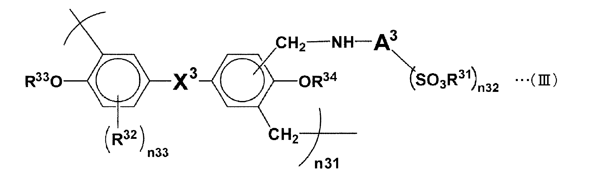
式(II)で表される構造単位、及び、式(III)で表される構造単位の比率は、特に制限はなく、合成条件等によって変化し得る。ビスフェノール系樹脂としては、式(II)で表される構造単位、及び、式(III)で表される構造単位のいずれか一方のみを有する樹脂を用いてもよい。
The ratio of the structural unit represented by the formula (II) and the structural unit represented by the formula (III) is not particularly limited, and may vary depending on synthesis conditions and the like. As the bisphenol-based resin, a resin having only one of the structural unit represented by the formula (II) and the structural unit represented by the formula (III) may be used.
前記X2及びX3としては、例えば、アルキリデン基(メチリデン基、エチリデン基、イソプロピリデン基、sec-ブチリデン基等)、シクロアルキリデン基(シクロヘキシリデン基等)、フェニルアルキリデン基(ジフェニルメチリデン基、フェニルエチリデン基等)などの有機基;スルホニル基が挙げられ、充電受入性に更に優れる観点からはイソプロピリデン基(-C(CH3)2-)が好ましく、放電特性に更に優れる観点からはスルホニル基(-SO2-)が好ましい。前記X2及びX3は、フッ素原子等のハロゲン原子により置換されていてもよい。前記X2及びX3がシクロアルキリデン基である場合、炭化水素環はアルキル基等により置換されていてもよい。
Examples of X 2 and X 3 include alkylidene groups (methylidene groups, ethylidene groups, isopropylidene groups, sec-butylidene groups, etc.), cycloalkylidene groups (cyclohexylidene groups, etc.), phenylalkylidene groups (diphenylmethylidene groups). , A phenylsulfonyl group, and the like; a sulfonyl group, and the isopropylidene group (—C (CH 3 ) 2 —) is preferable from the viewpoint of further excellent charge acceptance, and from the viewpoint of further excellent discharge characteristics. A sulfonyl group (—SO 2 —) is preferred. X 2 and X 3 may be substituted with a halogen atom such as a fluorine atom. When X 2 and X 3 are cycloalkylidene groups, the hydrocarbon ring may be substituted with an alkyl group or the like.
A2及びA3としては、例えば、メチレン基、エチレン基、プロピレン基、ブチレン基等の炭素数1~4のアルキレン基;フェニレン基、ナフチレン基等の2価のアリーレン基が挙げられる。前記アリーレン基は、アルキル基等により置換されていてもよい。
Examples of A 2 and A 3 include alkylene groups having 1 to 4 carbon atoms such as a methylene group, an ethylene group, a propylene group, and a butylene group; and divalent arylene groups such as a phenylene group and a naphthylene group. The arylene group may be substituted with an alkyl group or the like.
R21、R23、R24、R31、R33及びR34のアルカリ金属としては、ナトリウム、カリウム等が挙げられる。n21及びn31は、サイクル特性及び溶媒への溶解性に更に優れる観点から、1~150が好ましく、10~150がより好ましい。n22及びn32は、サイクル特性、放電特性及び充電受入性がバランス良く向上しやすい観点から、1又は2が好ましく、1がより好ましい。n23及びn33は、製造条件により変化するが、サイクル特性及びビスフェノール系樹脂の保存安定性に更に優れる観点から、0が好ましい。
Examples of the alkali metal for R 21 , R 23 , R 24 , R 31 , R 33 and R 34 include sodium and potassium. n21 and n31 are preferably 1 to 150, more preferably 10 to 150, from the viewpoint of further excellent cycle characteristics and solubility in a solvent. n22 and n32 are preferably 1 or 2, and more preferably 1, from the viewpoint that the cycle characteristics, discharge characteristics, and charge acceptability are easily improved in a balanced manner. Although n23 and n33 change with manufacturing conditions, 0 is preferable from a viewpoint which is further excellent in cycling characteristics and the storage stability of bisphenol-type resin.
スルホン基及び/又はスルホン酸塩基を有する樹脂(ビスフェノール系樹脂等)の重量平均分子量は、スルホン基及び/又はスルホン酸塩基を有する樹脂が鉛蓄電池において電極から電解液に溶出することを抑制することによりサイクル特性が向上しやすくなる観点から、3000以上が好ましく、10000以上がより好ましく、20000以上が更に好ましく、30000以上が特に好ましい。スルホン基及び/又はスルホン酸塩基を有する樹脂の重量平均分子量は、電極活物質に対する吸着性が低下して分散性が低下することを抑制することによりサイクル特性が向上しやすくなる観点から、200000以下が好ましく、150000以下がより好ましく、100000以下が更に好ましい。
The weight average molecular weight of a resin having a sulfonic group and / or a sulfonic acid group (such as a bisphenol-based resin) suppresses the elution of a resin having a sulfonic group and / or a sulfonic acid group from an electrode to an electrolytic solution in a lead storage battery. Is preferably 3000 or more, more preferably 10,000 or more, still more preferably 20000 or more, and particularly preferably 30000 or more. The weight average molecular weight of the resin having a sulfone group and / or a sulfonate group is 200000 or less from the viewpoint that the cycle characteristics are easily improved by suppressing the adsorptivity to the electrode active material and the dispersibility. Is preferable, 150,000 or less is more preferable, and 100,000 or less is still more preferable.
スルホン基及び/又はスルホン酸塩基を有する樹脂の重量平均分子量は、例えば、下記条件のゲルパーミエイションクロマトグラフィー(以下、「GPC」という)により測定することができる。
(GPC条件)
装置:高速液体クロマトグラフ LC-2200 Plus(日本分光株式会社製)
ポンプ:PU-2080
示差屈折率計:RI-2031
検出器:紫外可視吸光光度計UV-2075(λ:254nm)
カラムオーブン:CO-2065
カラム:TSKgel SuperAW(4000)、TSKgel SuperAW(3000)、TSKgel SuperAW(2500)(東ソー株式会社製)
カラム温度:40℃
溶離液:LiBr(10mmol/L)及びトリエチルアミン(200mmol/L)を含有するメタノール溶液
流速:0.6mL/分
分子量標準試料:ポリエチレングリコール(分子量:1.10×10⁶、5.80×10⁵、2.55×10⁵、1.46×10⁵、1.01×10⁵、4.49×10⁴、2.70×10⁴、2.10×10⁴;東ソー株式会社製)、ジエチレングリコール(分子量:1.06×10²;キシダ化学株式会社製)、ジブチルヒドロキシトルエン(分子量:2.20×10²;キシダ化学株式会社製) The weight average molecular weight of the resin having a sulfone group and / or a sulfonate group can be measured, for example, by gel permeation chromatography (hereinafter referred to as “GPC”) under the following conditions.
(GPC conditions)
Apparatus: High performance liquid chromatograph LC-2200 Plus (manufactured by JASCO Corporation)
Pump: PU-2080
Differential refractometer: RI-2031
Detector: UV-visible spectrophotometer UV-2075 (λ: 254 nm)
Column oven: CO-2065
Column: TSKgel SuperAW (4000), TSKgel SuperAW (3000), TSKgel SuperAW (2500) (manufactured by Tosoh Corporation)
Column temperature: 40 ° C
Eluent: methanol solution containing LiBr (10 mmol / L) and triethylamine (200 mmol / L) Flow rate: 0.6 mL / min Molecular weight standard sample: Polyethylene glycol (molecular weight: 1.10 × 10 6 , 5.80 × 10 5 2.55 × 10 5 , 1.46 × 10 5 , 1.01 × 10 5 , 4.49 × 10 4 , 2.70 × 10 4 , 2.10 × 10 4 ; manufactured by Tosoh Corporation), diethylene glycol (Molecular weight: 1.06 × 10 2 ; manufactured by Kishida Chemical Co., Ltd.), dibutylhydroxytoluene (Molecular weight: 2.20 × 10 2 ; manufactured by Kishida Chemical Co., Ltd.)
[炭素質材料(炭素質導電材)]
ところで、部分充電状態で使用される鉛蓄電池においては、放電の際に負極材中に生成される絶縁体である硫酸鉛が、充放電の繰り返しに伴って粗大化していく、サルフェーションと呼ばれる現象が早期に生じる。サルフェーションが起こると、充電受入性及び放電性能が著しく低下する。負極材に炭素質導電材を添加することにより、硫酸鉛の粗大化を抑制し、硫酸鉛を微細な状態に維持して、硫酸鉛から溶け出す鉛イオンの、電解液中の濃度が低下することを抑制し、充電受入性が高い状態を維持する効果が得られる。 [Carbonaceous material (carbonaceous conductive material)]
By the way, in a lead-acid battery used in a partially charged state, a phenomenon called sulfation, in which lead sulfate, which is an insulator generated in a negative electrode material during discharge, becomes coarser as charge and discharge are repeated, is a phenomenon called sulfation. It occurs early. When sulfation occurs, charge acceptability and discharge performance are significantly reduced. By adding a carbonaceous conductive material to the negative electrode material, the coarsening of lead sulfate is suppressed, the lead sulfate is kept in a fine state, and the concentration of lead ions dissolved from the lead sulfate decreases in the electrolyte. The effect which suppresses this and maintains a state with high charge acceptance is acquired.
炭素質材料(炭素質導電材)は、好ましくは、黒鉛、カーボンブラック、活性炭、炭素繊維及びカーボンナノチューブからなる材料群の中から選択される。好ましくは、黒鉛が選択され、さらに好ましくは、鱗片状黒鉛が選択される。鱗片状黒鉛の平均一次粒子径は、100μmよりも大きいことが好ましい。
The carbonaceous material (carbonaceous conductive material) is preferably selected from the material group consisting of graphite, carbon black, activated carbon, carbon fiber, and carbon nanotube. Preferably, graphite is selected, and more preferably, scaly graphite is selected. The average primary particle diameter of the flaky graphite is preferably larger than 100 μm.
ここでいう鱗片状黒鉛とは、JISM8601(2005)記載のものを指す。鱗片状黒鉛の電気抵抗率は、0.02Ω・cm以下であり、アセチレンブラック等のカーボンブラック類の電気抵抗率(0.1Ω・cm前後)より一桁小さい。したがって、従来の鉛蓄電池で用いられているカーボンブラック類に替えて鱗片状黒鉛を用いることにより、負極活物質の電気抵抗を下げて、充電受入性を更に向上することができる。
As used herein, flaky graphite refers to that described in JISM8601 (2005). The electrical resistivity of the flake graphite is 0.02 Ω · cm or less, which is an order of magnitude smaller than the electrical resistivity (around 0.1 Ω · cm) of carbon blacks such as acetylene black. Therefore, by using scale-like graphite instead of carbon blacks used in conventional lead-acid batteries, the electrical resistance of the negative electrode active material can be lowered and the charge acceptance can be further improved.
ここで、鱗片状黒鉛の平均一次粒子径は、JISM8511(2005)記載のレーザ回折・散乱法に準拠して求める。レーザ回折・散乱式粒度分布測定装置(日機装株式会社製:マイクロトラック9220FRA)を用い、分散剤として市販の界面活性剤ポリオキシエチレンオクチルフェニルエーテル(例えば、ロシュ・ダイアグノスティックス株式会社製:トリトンX-100)を0.5vol%含有する水溶液に鱗片状黒鉛試料を適量投入し、撹拌しながら40Wの超音波を180秒照射した後、測定を行なう。求められた平均粒子径(メディアン径:D50)の値を平均一次粒子径とする。
Here, the average primary particle diameter of the scaly graphite is obtained according to the laser diffraction / scattering method described in JISM8511 (2005). Using a laser diffraction / scattering type particle size distribution measuring device (Nikkiso Co., Ltd .: Microtrac 9220FRA), a commercially available surfactant polyoxyethylene octylphenyl ether (for example, Roche Diagnostics Co., Ltd .: Triton) as a dispersant. An appropriate amount of a scaly graphite sample is put into an aqueous solution containing 0.5 vol% of X-100), 40 W ultrasonic waves are irradiated for 180 seconds while stirring, and then measurement is performed. The obtained average particle diameter (median diameter: D50) is defined as the average primary particle diameter.
炭素質材料(炭素質導電材)の含有量は、満充電状態の負極活物質(海綿状金属鉛)100質量部に対し0.1~3質量部の範囲とするのが好ましい。
The content of the carbonaceous material (carbonaceous conductive material) is preferably in the range of 0.1 to 3 parts by mass with respect to 100 parts by mass of the fully charged negative electrode active material (sponge metal lead).
補強用短繊維は、アクリル繊維、ポリエチレン繊維、ポリプロピレン繊維、ポリエチレンテレフタレート繊維、炭素繊維等が挙げられる。
Examples of reinforcing short fibers include acrylic fibers, polyethylene fibers, polypropylene fibers, polyethylene terephthalate fibers, and carbon fibers.
[負極材に対する正極材の質量比]
負極材に対する正極材の質量比(正極材/負極材)は、充分な電池容量が得られやすいと共に高い充電受入性が得られやすい観点から、0.9以上が好ましく、1以上がより好ましく、1.05以上が更に好ましい。負極材に対する正極材の質量比は、充分な電池容量が得られやすい観点から、1.6以下が好ましく、1.5以下がより好ましく、1.4以下が更に好ましい。負極材に対する正極材の質量比は、1.3以下であってもよい。負極材に対する正極材の質量比は、充分な電池容量が得られやすいと共に高い充電受入性が得られやすい観点から、0.9~1.6が好ましく、1~1.5がより好ましく、1.05~1.4が更に好ましい。負極材に対する正極材の質量比は、1.05~1.3であってもよい。負極材に対する正極材の前記質量比は、化成後の負極材及び正極材の質量比である。 [Mass ratio of positive electrode material to negative electrode material]
The mass ratio of the positive electrode material to the negative electrode material (positive electrode material / negative electrode material) is preferably 0.9 or more, more preferably 1 or more, from the viewpoint that sufficient battery capacity is easily obtained and high charge acceptance is easily obtained. 1.05 or more is still more preferable. The mass ratio of the positive electrode material to the negative electrode material is preferably 1.6 or less, more preferably 1.5 or less, and even more preferably 1.4 or less, from the viewpoint that a sufficient battery capacity is easily obtained. The mass ratio of the positive electrode material to the negative electrode material may be 1.3 or less. The mass ratio of the positive electrode material to the negative electrode material is preferably 0.9 to 1.6, more preferably 1 to 1.5, from the viewpoint that a sufficient battery capacity is easily obtained and high charge acceptance is easily obtained. .05 to 1.4 is more preferable. The mass ratio of the positive electrode material to the negative electrode material may be 1.05 to 1.3. The said mass ratio of the positive electrode material with respect to a negative electrode material is a mass ratio of the negative electrode material and positive electrode material after chemical conversion.
(電解液)
次に、電槽2に収容される電解液について説明する。電解液は、例えば、硫酸を含有している。電解液は、ナトリウムイオン及び/又はアルミニウムイオンを含有してよい。電解液は、減液性能に更に優れる観点及び過放電時の短絡を抑制できる観点から、アルミニウムイオンを含有することが好ましい。電解液がアルミニウムイオンを含有することにより過放電時の短絡を抑制できる理由は、水酸化アルミニウムがセパレータ内、特に表層部に析出しやくなり、鉛の析出が抑制されるためであると推測される。 (Electrolyte)
Next, the electrolyte solution accommodated in thebattery case 2 will be described. The electrolytic solution contains, for example, sulfuric acid. The electrolytic solution may contain sodium ions and / or aluminum ions. The electrolytic solution preferably contains aluminum ions from the viewpoint of further excellent liquid reduction performance and the viewpoint of suppressing a short circuit during overdischarge. The reason why the electrolytic solution contains aluminum ions can suppress a short circuit during overdischarge is presumed to be because aluminum hydroxide tends to precipitate in the separator, particularly the surface layer portion, and lead precipitation is suppressed. The
次に、電槽2に収容される電解液について説明する。電解液は、例えば、硫酸を含有している。電解液は、ナトリウムイオン及び/又はアルミニウムイオンを含有してよい。電解液は、減液性能に更に優れる観点及び過放電時の短絡を抑制できる観点から、アルミニウムイオンを含有することが好ましい。電解液がアルミニウムイオンを含有することにより過放電時の短絡を抑制できる理由は、水酸化アルミニウムがセパレータ内、特に表層部に析出しやくなり、鉛の析出が抑制されるためであると推測される。 (Electrolyte)
Next, the electrolyte solution accommodated in the
電解液がアルミニウムイオンを含有する場合、前記電解液中のアルミニウムイオンの含有量、すなわち、アルミニウムイオンの濃度(アルミニウムイオン濃度)は、減液性能を改善する効果が顕著となる観点から、電解液量に対して、0.001mol/L以上が好ましく、0.03mol/L以上がより好ましく、0.06mol/L以上が更に好ましい。また、アルミニウムイオンの濃度は、減液性能を改善する効果が顕著となる観点から、電解液量に対して、0.2mol/L以下が好ましい。以上のことから、アルミニウムイオンの濃度は、0.001~0.2mol/Lが好ましく、0.03~0.2mol/Lがより好ましく、0.06~0.2mol/Lが更に好ましい。電解液のアルミニウムイオン濃度は、例えば、ICP発光分光分析法(高周波誘導結合プラズマ発光分光分析法)により測定することができる。
In the case where the electrolytic solution contains aluminum ions, the content of aluminum ions in the electrolytic solution, that is, the concentration of aluminum ions (aluminum ion concentration) is from the viewpoint that the effect of improving the liquid reduction performance becomes remarkable. 0.001 mol / L or more is preferable with respect to the amount, 0.03 mol / L or more is more preferable, and 0.06 mol / L or more is still more preferable. Further, the concentration of aluminum ions is preferably 0.2 mol / L or less with respect to the amount of the electrolytic solution from the viewpoint that the effect of improving the liquid reduction performance becomes remarkable. From the above, the concentration of aluminum ions is preferably 0.001 to 0.2 mol / L, more preferably 0.03 to 0.2 mol / L, and still more preferably 0.06 to 0.2 mol / L. The aluminum ion concentration of the electrolytic solution can be measured by, for example, ICP emission spectroscopy (high frequency inductively coupled plasma emission spectroscopy).
アルミニウムイオンを含有する電解液は、例えば、硫酸及び硫酸アルミニウム(例えば、硫酸アルミニウム粉末)を混合することにより得ることができる。前記電解液中に溶解させる硫酸アルミニウムは、無水物又は水和物として添加することができる。
The electrolytic solution containing aluminum ions can be obtained, for example, by mixing sulfuric acid and aluminum sulfate (for example, aluminum sulfate powder). Aluminum sulfate dissolved in the electrolytic solution can be added as an anhydride or a hydrate.
化成後の電解液(例えば、アルミニウムイオンを含む電解液)の比重は下記の範囲であってよい。電解液の比重は、浸透短絡又は凍結を抑制すると共に放電特性に優れる観点(例えば、低温高率放電性能に優れる観点)から、例えば、1.25以上が好ましく、1.28以上がより好ましく、1.285以上が更に好ましく、1.29以上が特に好ましい。電解液の比重は、充電受入性が向上する観点及びISSサイクル特性が更に向上する観点から、1.33以下が好ましく、1.32以下がより好ましく、1.315以下が更に好ましく、1.31以下が特に好ましい。電解液の比重の値は、例えば、浮式比重計、又は、京都電子工業株式会社製のデジタル比重計によって測定することができる。
The specific gravity of the electrolytic solution after chemical conversion (for example, an electrolytic solution containing aluminum ions) may be in the following range. The specific gravity of the electrolytic solution is preferably, for example, 1.25 or more, more preferably 1.28 or more, from the viewpoint of suppressing osmotic short-circuiting or freezing and being excellent in discharge characteristics (for example, excellent in low-temperature high-rate discharge performance). 1.285 or more are still more preferable, and 1.29 or more are especially preferable. The specific gravity of the electrolytic solution is preferably 1.33 or less, more preferably 1.32 or less, still more preferably 1.315 or less, and 1.31 from the viewpoint of improving charge acceptability and further improving ISS cycle characteristics. The following are particularly preferred: The value of the specific gravity of the electrolytic solution can be measured by, for example, a floating hydrometer or a digital hydrometer manufactured by Kyoto Electronics Industry Co., Ltd.
<鉛蓄電池の製造方法>
本実施形態に係る液式鉛蓄電池の製造方法は、一つ又は複数の隔壁51によって二つ以上の領域52に区切られた電槽2を準備する工程と、複数の正極板12と複数のセパレータ(例えば袋状のセパレータ14)と複数の負極板13とをそれぞれ含む、二つ以上の極板群11を準備する工程と、電槽2の領域52に極板群11を収容する工程と、電槽2内に電解液を供給する工程と、を備える。本実施形態に係る製造方法では、電槽2の領域52に極板群11を収容する際、極板群11の厚さ方向の圧縮力を隔壁51から極板群11に付与しながら、領域52に対して極板群を押し込む。 <Method for producing lead-acid battery>
The method for manufacturing a liquid lead-acid battery according to this embodiment includes a step of preparing abattery case 2 divided into two or more regions 52 by one or a plurality of partition walls 51, a plurality of positive plates 12 and a plurality of separators. A step of preparing two or more electrode plate groups 11 each including (for example, a bag-like separator 14) and a plurality of negative electrode plates 13, a step of accommodating the electrode plate group 11 in the region 52 of the battery case 2, Supplying an electrolytic solution into the battery case 2. In the manufacturing method according to the present embodiment, when the electrode plate group 11 is accommodated in the region 52 of the battery case 2, the compressing force in the thickness direction of the electrode plate group 11 is applied to the electrode plate group 11 from the partition wall 51. The electrode plate group is pushed into 52.
本実施形態に係る液式鉛蓄電池の製造方法は、一つ又は複数の隔壁51によって二つ以上の領域52に区切られた電槽2を準備する工程と、複数の正極板12と複数のセパレータ(例えば袋状のセパレータ14)と複数の負極板13とをそれぞれ含む、二つ以上の極板群11を準備する工程と、電槽2の領域52に極板群11を収容する工程と、電槽2内に電解液を供給する工程と、を備える。本実施形態に係る製造方法では、電槽2の領域52に極板群11を収容する際、極板群11の厚さ方向の圧縮力を隔壁51から極板群11に付与しながら、領域52に対して極板群を押し込む。 <Method for producing lead-acid battery>
The method for manufacturing a liquid lead-acid battery according to this embodiment includes a step of preparing a
二つ以上の極板群11を準備する工程における正極板12及び負極板13は、未化成の正極板及び負極板である。二つ以上の極板群11を準備する工程は、例えば、未化成の電極板(未化成の正極板及び未化成の負極板)を得る電極板製造工程と、電極板製造工程で得られた未化成の負極板を内部に配置した袋状のセパレータ14及び未化成の正極板を交互に積層させ(図4参照)、同極性の電極の集電部をストラップで連結(溶接等)させて極板群11を得る工程と、を有していてよい。
The positive electrode plate 12 and the negative electrode plate 13 in the step of preparing two or more electrode plate groups 11 are an unformed positive electrode plate and negative electrode plate. The step of preparing two or more electrode plate groups 11 was obtained by, for example, an electrode plate manufacturing step for obtaining an unformed electrode plate (an unformed positive plate and an unformed negative plate) and an electrode plate manufacturing step. By alternately laminating the bag-shaped separator 14 with the unformed negative electrode plate disposed therein and the unformed positive plate (see FIG. 4), and connecting the current collecting portions of the electrodes of the same polarity with a strap (welding etc.) And obtaining the electrode plate group 11.
電極板製造工程では、例えば、電極材ペースト(正極材ペースト及び負極材ペースト)を集電体(例えば、鋳造格子体、エキスパンド格子体等の集電体格子)に充填した後に、熟成及び乾燥を行うことにより未化成の電極板を得る。正極材ペーストは、例えば、正極活物質の原料(鉛粉等)を含有しており、他の添加剤を更に含有していてもよい。負極材ペーストは、負極活物質の原料(鉛粉等)を含有しており、他の添加剤(例えば分散剤)を更に含有していてもよい。負極材ペーストは、分散剤として、スルホン基及び/又はスルホン酸塩基を有する樹脂(ビスフェノール系樹脂等)を含有していることが好ましい。
In the electrode plate manufacturing process, for example, an electrode material paste (a positive electrode material paste and a negative electrode material paste) is filled in a current collector (for example, a current collector grid such as a cast grid, an expanded grid, etc.), and then aged and dried. By performing this, an unformed electrode plate is obtained. The positive electrode material paste contains, for example, a raw material (lead powder or the like) of the positive electrode active material, and may further contain other additives. The negative electrode material paste contains a raw material (lead powder or the like) of the negative electrode active material, and may further contain other additives (for example, a dispersant). The negative electrode material paste preferably contains a resin having a sulfone group and / or a sulfonate group (such as a bisphenol resin) as a dispersant.
正極材ペーストは、例えば、下記の方法により得ることができる。まず、正極活物質の原料に添加剤(補強用短繊維等)及び水を加える。次に、希硫酸を加えた後、混練して正極材ペーストが得られる。正極材ペーストを作製するに際しては、化成時間を短縮できる観点から、正極活物質の原料として鉛丹(Pb3O4)を用いてもよい。この正極材ペーストを正極集電体21に充填した後に熟成及び乾燥を行うことにより未化成の正極板を得ることができる。
The positive electrode material paste can be obtained, for example, by the following method. First, an additive (such as reinforcing short fibers) and water are added to the raw material of the positive electrode active material. Next, after adding dilute sulfuric acid, the mixture is kneaded to obtain a positive electrode material paste. In producing the positive electrode material paste, lead (Pb 3 O 4 ) may be used as a raw material for the positive electrode active material from the viewpoint of shortening the chemical formation time. After filling this positive electrode material paste into the positive electrode current collector 21, aging and drying are performed to obtain an unformed positive electrode plate.
正極材ペーストにおいて補強用短繊維を用いる場合、補強用短繊維の配合量は、正極活物質の原料(鉛粉等)の全質量を基準として、0.005~0.3質量%が好ましく、0.05~0.3質量%がより好ましい。
When reinforcing short fibers are used in the positive electrode material paste, the blending amount of the reinforcing short fibers is preferably 0.005 to 0.3% by mass based on the total mass of the positive electrode active material (lead powder, etc.) 0.05 to 0.3% by mass is more preferable.
未化成の正極板を得るための熟成条件としては、温度35~85℃、湿度50~98RH%の雰囲気で15~60時間が好ましい。乾燥条件は、温度45~80℃で15~30時間が好ましい。
As aging conditions for obtaining an unformed positive electrode plate, 15 to 60 hours are preferable in an atmosphere of a temperature of 35 to 85 ° C. and a humidity of 50 to 98 RH%. The drying conditions are preferably 45 to 80 ° C. and 15 to 30 hours.
負極材ペーストは、例えば、下記の方法により得ることができる。まず、負極活物質の原料に添加剤(スルホン基及び/又はスルホン酸塩基を有する樹脂、補強用短繊維、硫酸バリウム等)を添加して乾式混合することにより混合物を得る。そして、この混合物に硫酸(希硫酸等)及び溶媒(イオン交換水等の水、有機溶媒など)を加えて混練することにより負極材ペーストが得られる。この負極材ペーストを負極集電体31(例えば、鋳造格子体、エキスパンド格子体等の集電体格子)に充填した後に熟成及び乾燥を行うことにより未化成の負極板を得ることができる。
The negative electrode material paste can be obtained, for example, by the following method. First, an additive (a resin having a sulfone group and / or a sulfonate group, a reinforcing short fiber, barium sulfate, etc.) is added to the raw material of the negative electrode active material and dry mixed to obtain a mixture. And a negative electrode material paste is obtained by adding and knead | mixing a sulfuric acid (diluted sulfuric acid etc.) and a solvent (water, such as ion-exchange water, an organic solvent) to this mixture. An unformed negative electrode plate can be obtained by filling the negative electrode material paste into a negative electrode current collector 31 (for example, a current collector grid such as a cast grid or an expanded grid) and then aging and drying.
負極材ペーストにおいて、スルホン基及び/又はスルホン酸塩基を有する樹脂(ビスフェノール系樹脂等)、炭素質材料、補強用短繊維又は硫酸バリウムを用いる場合、各成分の配合量は下記の範囲が好ましい。スルホン基及び/又はスルホン酸塩基を有する樹脂の配合量は、負極活物質の原料(鉛粉等)の全質量を基準として、樹脂固形分換算で、0.01~2.0質量%が好ましく、0.05~1.0質量%がより好ましく、0.1~0.5質量%が更に好ましく、0.1~0.3質量%が特に好ましい。炭素質材料の配合量は、負極活物質の原料(鉛粉等)の全質量を基準として、0.1~3質量%が好ましく、0.2~1.4質量%がより好ましい。補強用短繊維の配合量は、負極活物質の原料(鉛粉等)の全質量を基準として0.05~0.15質量%が好ましい。硫酸バリウムの配合量は、負極活物質の原料(鉛粉等)の全質量を基準として、0.01~2.0質量%が好ましく、0.01~1.0質量%がより好ましい。
In the negative electrode material paste, when a resin having a sulfone group and / or a sulfonate group (such as a bisphenol-based resin), a carbonaceous material, a reinforcing short fiber, or barium sulfate is used, the amount of each component is preferably in the following range. The amount of the resin having a sulfone group and / or a sulfonate group is preferably 0.01 to 2.0% by mass in terms of resin solid content based on the total mass of the raw material of the negative electrode active material (such as lead powder). 0.05 to 1.0 mass% is more preferable, 0.1 to 0.5 mass% is still more preferable, and 0.1 to 0.3 mass% is particularly preferable. The blending amount of the carbonaceous material is preferably from 0.1 to 3% by mass, more preferably from 0.2 to 1.4% by mass, based on the total mass of the negative electrode active material (such as lead powder). The blending amount of the reinforcing short fibers is preferably 0.05 to 0.15% by mass based on the total mass of the raw material of the negative electrode active material (lead powder or the like). The compounding amount of barium sulfate is preferably 0.01 to 2.0% by mass, more preferably 0.01 to 1.0% by mass, based on the total mass of the negative electrode active material (lead powder, etc.).
未化成の負極板を得るための熟成条件としては、温度45~65℃、湿度70~98RH%の雰囲気で15~30時間が好ましい。乾燥条件は、温度45~60℃で15~30時間が好ましい。
As aging conditions for obtaining an unformed negative electrode plate, 15 to 30 hours are preferable in an atmosphere of a temperature of 45 to 65 ° C. and a humidity of 70 to 98 RH%. The drying conditions are preferably 45 to 60 ° C. and 15 to 30 hours.
電槽2の領域52に極板群11を収容する工程では、図13に示すように、電槽2の領域52に対して極板群11を押し込むことにより、極板群11の厚さ方向の圧縮力を隔壁51から極板群11に付与しながら極板群11を電槽2内に収容する。これにより、未化成電池を作製する。なお、隔壁51と対向する面が電槽2の内壁面50である場合、隔壁51及び電槽2の内壁面50から極板群11の厚さ方向の圧縮力を極板群11に付与する。
In the step of accommodating the electrode plate group 11 in the region 52 of the battery case 2, the electrode plate group 11 is pushed into the region 52 of the battery case 2 as shown in FIG. The electrode plate group 11 is accommodated in the battery case 2 while applying the compressive force from the partition wall 51 to the electrode plate group 11. Thereby, an unformed battery is produced. In addition, when the surface facing the partition 51 is the inner wall surface 50 of the battery case 2, a compressive force in the thickness direction of the electrode plate group 11 is applied to the electrode plate group 11 from the partition wall 51 and the inner wall surface 50 of the battery case 2. .
本実施形態では、電槽2の領域52に極板群11を収容する作業をしやすい観点から、クリアランス(X-Y)を-1.1以上とすることが好ましく、-1.0以上とすることがより好ましく、-0.6以上とすることが更に好ましい。また、極板間距離を厳密に設定しやすい観点から、クリアランス(X-Y)を1.2以下とすることが好ましく、1.0以下とすることがより好ましく、0.0以下とすることが更に好ましく、0.0未満とすることが特に好ましい。これらの観点から、クリアランス(X-Y)を-1.1~1.2とすることが好ましく、-1.0~1.0とすることがより好ましく、-0.6~0.0とすることが更に好ましく、-0.6以上0.0未満とすることが特に好ましい。なお、本発明者らの知見によれば、クリアランス(X-Y)が1.16以上である場合には極板群11を押し込むことなく、極板群11を自重により電槽2の領域52内に落とし込むことができるが、クリアランス(X-Y)が1.16より小さい場合には、極板群11に対して圧力Fを加えて、電槽2の領域52に対して極板群11を押し込む必要がある。クリアランス(X-Y)が正の値である場合にも、極板群11を電槽2の領域52に対して押し込む必要がある理由は、明らかではないが、図13(a)に示すように、極板群11が下方に広がった構造を有しているためであると推察される。
In the present embodiment, from the viewpoint of facilitating the work of housing the electrode plate group 11 in the region 52 of the battery case 2, the clearance (XY) is preferably −1.1 or more, and is −1.0 or more. More preferably, it is more preferably −0.6 or more. Further, from the viewpoint of easily setting the distance between the electrode plates, the clearance (XY) is preferably 1.2 or less, more preferably 1.0 or less, and 0.0 or less. Is more preferable, and it is particularly preferable to set it to less than 0.0. From these viewpoints, the clearance (XY) is preferably −1.1 to 1.2, more preferably −1.0 to 1.0, and −0.6 to 0.0. More preferably, it is more preferably −0.6 or more and less than 0.0. According to the knowledge of the present inventors, when the clearance (XY) is 1.16 or more, the electrode plate group 11 is not pushed in, and the electrode plate 11 is moved by its own weight in the region 52 of the battery case 2. If the clearance (XY) is smaller than 1.16, pressure F is applied to the electrode plate group 11 and the electrode plate group 11 is applied to the region 52 of the battery case 2. It is necessary to push in. Even when the clearance (XY) is a positive value, the reason why it is necessary to push the electrode plate group 11 into the region 52 of the battery case 2 is not clear, but as shown in FIG. In addition, it is assumed that the electrode plate group 11 has a structure that spreads downward.
本実施形態では、上記クリアランスに応じて極板群11の厚さ方向に圧縮力が付与されるため、極板群11の上方に圧力Fを付与することで、電槽2の領域52に対して極板群11を押し込む必要がある。
In the present embodiment, a compressive force is applied in the thickness direction of the electrode plate group 11 in accordance with the clearance. Therefore, by applying a pressure F above the electrode plate group 11, the region 52 of the battery case 2 is applied. It is necessary to push in the electrode plate group 11.
電槽2内に電解液を供給する工程では、上記電槽2の領域52に極板群11を収容する工程により得られた未化成電池の電槽2内に電解液を供給(注入)する。
In the step of supplying the electrolytic solution into the battery case 2, the electrolytic solution is supplied (injected) into the battery case 2 of the unformed battery obtained by the step of housing the electrode plate group 11 in the region 52 of the battery case 2. .
本実施形態に係る製造方法は、電解液を供給した後の未化成電池を化成する工程を更に備えていてよい。当該工程は、例えば、電解液を供給した後、直流電流を通電して電槽化成する工程であってよい。化成後は、電解液の比重を適切な比重に調整してよい。これにより、化成された液式鉛蓄電池が得られる。
The manufacturing method according to the present embodiment may further include a step of forming an unformed battery after supplying the electrolytic solution. The step may be, for example, a step of forming a battery case by supplying a direct current and then supplying a electrolytic solution. After the formation, the specific gravity of the electrolytic solution may be adjusted to an appropriate specific gravity. Thereby, the formed chemical liquid lead acid battery is obtained.
化成条件及び硫酸の比重は電極活物質の性状に応じて調整することができる。また、化成処理は、未化成電池を得た後に実施されることに限られず、電極製造工程における熟成及び乾燥後に実施されてもよい(タンク化成)。
Chemical conversion conditions and specific gravity of sulfuric acid can be adjusted according to the properties of the electrode active material. Further, the chemical conversion treatment is not limited to being performed after obtaining the non-chemical conversion battery, and may be performed after aging and drying in the electrode manufacturing process (tank chemical conversion).
以下、実施例により本開示を具体的に説明する。但し、本開示は下記の実施例のみに限定されるものではない。
Hereinafter, the present disclosure will be specifically described by way of examples. However, the present disclosure is not limited to the following examples.
(実施例1)
<鉛蓄電池の作製>
[電槽の準備]
上面が開放された箱体からなり、内部が隔壁によって6つの領域に区切られた電槽(内部の厚さ方向の長さ:3.5cm)を準備した。隔壁及び隔壁と対向する電槽の内壁面は、平坦部と、平坦部から隆起した、電槽の高さ方向に延びる複数のリブ部と、領域の入口側に設けられており平坦部からリブ部に至る傾斜部とを有しており、リブの高さは1.4mmであった。また、各領域の幅X(単位:mm)は32.2であった。なお、本実施例では、電槽に収容された極板群11の最も外側に位置する極板の上部周縁部と電極材充填部との境界より±3mmの高さにおいて領域の幅Xを測定した。 Example 1
<Production of lead acid battery>
[Preparation of battery case]
A battery case (inner thickness direction length: 3.5 cm) having a box body with an open upper surface and having an interior divided into six regions by partition walls was prepared. The partition wall and the inner wall surface of the battery case facing the partition wall are a flat part, a plurality of rib parts protruding from the flat part and extending in the height direction of the battery case, and provided on the entrance side of the region. And the height of the rib was 1.4 mm. The width X (unit: mm) of each region was 32.2. In this example, the width X of the region is measured at a height of ± 3 mm from the boundary between the upper peripheral edge of theelectrode plate 11 located on the outermost side of the electrode plate group 11 accommodated in the battery case and the electrode material filling portion. did.
<鉛蓄電池の作製>
[電槽の準備]
上面が開放された箱体からなり、内部が隔壁によって6つの領域に区切られた電槽(内部の厚さ方向の長さ:3.5cm)を準備した。隔壁及び隔壁と対向する電槽の内壁面は、平坦部と、平坦部から隆起した、電槽の高さ方向に延びる複数のリブ部と、領域の入口側に設けられており平坦部からリブ部に至る傾斜部とを有しており、リブの高さは1.4mmであった。また、各領域の幅X(単位:mm)は32.2であった。なお、本実施例では、電槽に収容された極板群11の最も外側に位置する極板の上部周縁部と電極材充填部との境界より±3mmの高さにおいて領域の幅Xを測定した。 Example 1
<Production of lead acid battery>
[Preparation of battery case]
A battery case (inner thickness direction length: 3.5 cm) having a box body with an open upper surface and having an interior divided into six regions by partition walls was prepared. The partition wall and the inner wall surface of the battery case facing the partition wall are a flat part, a plurality of rib parts protruding from the flat part and extending in the height direction of the battery case, and provided on the entrance side of the region. And the height of the rib was 1.4 mm. The width X (unit: mm) of each region was 32.2. In this example, the width X of the region is measured at a height of ± 3 mm from the boundary between the upper peripheral edge of the
[正極板の作製]
正極活物質の原料として、鉛粉及び鉛丹(Pb3O4)を用いた(鉛粉:鉛丹=96:4(質量比))。正極活物質の原料と、正極活物質の原料の全質量を基準として0.07質量%の補強用短繊維(アクリル繊維)と、水とを混合して混練した。続いて、希硫酸(比重1.280、20℃換算以下同様)を少量ずつ添加しながら混練して、正極材ペーストを作製した。鉛合金からなる圧延シートにエキスパンド加工を施すことにより作製されたエキスパンド格子体(集電体)にこの正極材ペーストを充填した。次いで、正極材ペーストが充填された集電体を温度50℃、湿度98%の雰囲気で24時間熟成した。その後、乾燥して未化成の正極板を得た。 [Production of positive electrode plate]
Lead powder and red lead (Pb 3 O 4 ) were used as raw materials for the positive electrode active material (lead powder: red lead = 96: 4 (mass ratio)). 0.07% by mass of reinforcing short fibers (acrylic fibers) based on the total mass of the positive electrode active material, the total mass of the positive electrode active material, and water were mixed and kneaded. Subsequently, dilute sulfuric acid (specific gravity 1.280, equivalent to 20 ° C. or lower) was kneaded while being added little by little to prepare a positive electrode material paste. This positive electrode material paste was filled in an expanded lattice (current collector) produced by subjecting a rolled sheet made of a lead alloy to an expanding process. Next, the current collector filled with the positive electrode material paste was aged in an atmosphere of a temperature of 50 ° C. and a humidity of 98% for 24 hours. Then, it dried and obtained the unchemically formed positive electrode plate.
[負極板の作製]
負極活物質の原料として鉛粉を用いた。ビスフェノール系樹脂を0.2質量%(固形分換算、日本製紙(株)製、商品名:ビスパーズP215)、補強用短繊維(アクリル繊維)を0.1質量%、硫酸バリウムを1.0質量%、及び、炭素質材料(鱗片状黒鉛、平均粒径(メディアン径:D50):180μm)を2.0質量%含む混合物を前記鉛粉に添加した後に乾式混合した(前記配合量は、負極活物質の原料の全質量を基準とした配合量である)。前記ビスフェノール系樹脂の重量平均分子量は、前記記載の条件のGPCにより測定したところ、53900であった。前記鱗片状黒鉛の粒径は、JISM8511(2005)記載のレーザ回折・散乱法に準拠して求めた。次に、水10質量%(負極活物質の原料の全質量を基準とした配合量である)を加えた後に混練した。続いて、希硫酸(比重1.280)9.5質量%(負極活物質の原料の全質量を基準とした配合量である)を少量ずつ添加しながら混練して、負極材ペーストを作製した。続いて、鉛合金からなる圧延シートにエキスパンド加工を施すことにより作製されたエキスパンド格子体(集電体)に前記負極材ペーストを充填した。次いで、負極材ペーストが充填された集電体を温度50℃、湿度98%の雰囲気で24時間熟成した。その後、乾燥して未化成の負極板を得た。 [Production of negative electrode plate]
Lead powder was used as a raw material for the negative electrode active material. 0.2% by mass of bisphenol-based resin (converted to solid content, manufactured by Nippon Paper Industries Co., Ltd., trade name: Vispaz P215), 0.1% by mass of reinforcing short fibers (acrylic fibers), and 1.0% by mass of barium sulfate % And a carbonaceous material (flaky graphite, average particle diameter (median diameter: D50): 180 μm) was added to the lead powder and then dry-mixed (the blending amount is negative electrode The blending amount is based on the total mass of the active material). The weight average molecular weight of the bisphenol-based resin was 53900 as measured by GPC under the conditions described above. The particle size of the scaly graphite was determined based on the laser diffraction / scattering method described in JISM8511 (2005). Next, 10% by mass of water (a blending amount based on the total mass of the raw material of the negative electrode active material) was added and then kneaded. Subsequently, dilute sulfuric acid (specific gravity 1.280) 9.5% by mass (mixing amount based on the total mass of the negative electrode active material raw material) was added and kneaded little by little to prepare a negative electrode material paste. . Subsequently, the negative electrode material paste was filled in an expanded lattice (current collector) produced by subjecting a rolled sheet made of a lead alloy to an expanding process. Next, the current collector filled with the negative electrode material paste was aged in an atmosphere of a temperature of 50 ° C. and a humidity of 98% for 24 hours. Thereafter, it was dried to obtain an unformed negative electrode plate.
[袋状のセパレータの作製]
まず、微多孔シートからなり、一方面に複数の線状のリブを有する所定寸法長さのセパレータ(ポリエチレン製、ベース部の厚さT:0.2mm、リブの高さH:0.55mm)を準備し、当該セパレータのリブを設けていない面の長手方向のおおよそ中央においてU字状に折り曲げ、積層シートを得た。続いて、前記積層シートの両側部をメカニカルシールし、袋状のセパレータを得た。 [Production of bag-shaped separator]
First, a separator having a predetermined length made of a microporous sheet and having a plurality of linear ribs on one side (made of polyethylene, base portion thickness T: 0.2 mm, rib height H: 0.55 mm) Was prepared and bent into a U-shape at approximately the center in the longitudinal direction of the surface on which the ribs of the separator were not provided, to obtain a laminated sheet. Subsequently, both side portions of the laminated sheet were mechanically sealed to obtain a bag-shaped separator.
[極板群の作製]
袋状のセパレータ内に未化成の負極板を配置した。未化成の負極板を入れた袋状のセパレータ8枚と未化成の正極板7枚と、を交互に積層した。続いて、キャストオンストラップ(COS)方式で同極性の極板の耳部同士を溶接して極板群を作製した。ストラップ部は、Pb-Sb系合金からなり、ストラップ部の質量に対するSbの含有量は2.9質量%とした。極板群の厚さY(単位:mm)は31.2であった。 [Production of electrode group]
An unchemically formed negative electrode plate was placed in a bag-shaped separator. Eight bag-like separators containing unformed negative plates and seven unformed positive plates were alternately laminated. Subsequently, the ears of the same polarity electrode plates were welded together by a cast on strap (COS) method to produce an electrode plate group. The strap portion was made of a Pb—Sb alloy, and the Sb content was 2.9% by mass with respect to the mass of the strap portion. The thickness Y (unit: mm) of the electrode plate group was 31.2.
[電解液の調製]
化成後の電解液におけるナトリウムイオン濃度が0.1mol/Lとなるように、希硫酸に硫酸ナトリウムを加えて電解液を調製した。なお、電解液は、化成後の電解液の比重が1.290となるような比重とした。 [Preparation of electrolyte]
An electrolyte solution was prepared by adding sodium sulfate to dilute sulfuric acid so that the sodium ion concentration in the electrolyte solution after chemical conversion was 0.1 mol / L. The electrolyte solution had a specific gravity such that the specific gravity of the electrolyte solution after chemical conversion was 1.290.
[電池の組み立て]
極板群を電槽の領域に押し込むことにより収容し、12V電池(JIS D 5301規定のD23サイズに相当)を組み立てた。電解液をこの電池に注入し、その後、35℃の水槽中、通電電流18.6Aで18時間の条件で化成して液式鉛蓄電池を得た。化成後に測定した各種物性値を以下に示す。正極活物質の平均粒径は、0.8μmであった。正極材の比表面積は、6m2/gであった。負極活物質の平均粒径は、1.2μmであった。負極材の比表面積は、1.0m2/gであった。負極材に対する正極材の質量比(正極材/負極材)は1.4であった。また、化成後の電解液の比重は1.290であった。極板群厚さY(単位:mm)は31.2であった。電槽の領域の幅Xが32.2であったことから、クリアランス(X-Y)は1.0であった。なお、本実施例では、化成後の極板群厚さY(単位:mm)は、化成後の電池より極板群を取り出し1時間水洗をし、電解液の取り除かれた極板群を酸素の存在しない系において十分に乾燥させてから測定した。 [Battery assembly]
The electrode plate group was accommodated by being pushed into the battery case region, and a 12V battery (corresponding to D23 size defined in JIS D 5301) was assembled. The electrolytic solution was poured into this battery, and then formed in a 35 ° C. water bath at a current of 18.6 A for 18 hours to obtain a liquid lead acid battery. Various physical property values measured after chemical conversion are shown below. The average particle diameter of the positive electrode active material was 0.8 μm. The specific surface area of the positive electrode material was 6 m 2 / g. The average particle diameter of the negative electrode active material was 1.2 μm. The specific surface area of the negative electrode material was 1.0 m 2 / g. The mass ratio of the positive electrode material to the negative electrode material (positive electrode material / negative electrode material) was 1.4. Moreover, the specific gravity of the electrolyte solution after chemical conversion was 1.290. The electrode plate group thickness Y (unit: mm) was 31.2. Since the width X of the battery case area was 32.2, the clearance (XY) was 1.0. In this example, the electrode plate group thickness Y (unit: mm) after chemical conversion is determined by taking out the electrode plate group from the battery after chemical conversion and washing it with water for 1 hour. It was measured after sufficiently drying in a system in which no water was present.
[極板間距離の測定]
化成後の電池から取り出した極板群における極板間距離を以下の方法により測定した。まず、化成後の電池より極板群を取り出し1時間水洗をし、電解液の取り除かれた極板群を酸素の存在しない系において十分に乾燥させた。次いで、乾燥した極板群から、すべてのセパレータを抜き取った。抜き取った全てのセパレータについて、当該セパレータの上端から下端側に向かって約8mmの箇所でセパレータの厚さを測定し、測定値の平均値を極板間距離とした。上記セパレータの厚さの測定は、複数本形成されたリブのうち、幅方向の最も外側に配置された2本のリブ上及びそれらの中点に配置されたリブ上の計3点を測定することにより行い、測定した厚さの平均値をセパレータの厚さとした。化成後の電池から取り出した極板群における極板間距離は0.75mmであった。 [Measurement of distance between electrode plates]
The distance between the electrode plates in the electrode plate group taken out from the formed battery was measured by the following method. First, the electrode plate group was taken out from the formed battery and washed with water for 1 hour, and the electrode plate group from which the electrolyte solution was removed was sufficiently dried in a system without oxygen. Subsequently, all the separators were extracted from the dried electrode plate group. About all the separators extracted, the thickness of the separator was measured at a location of about 8 mm from the upper end to the lower end side of the separator, and the average value of the measured values was defined as the distance between the electrode plates. The thickness of the separator is measured on a total of three points on the two ribs arranged on the outermost side in the width direction and on the rib arranged on the midpoint among the plurality of formed ribs. The average value of the measured thickness was taken as the thickness of the separator. The distance between the electrode plates in the electrode plate group taken out from the formed battery was 0.75 mm.
(実施例2)
領域の幅X(単位:mm)が30.9である電槽を用いたこと以外は、実施例1と同様にして液式鉛蓄電池を作製した。化成後のクリアランス(X-Y)は-0.3であり、化成後の電池から取り出した極板群における極板間距離は0.75mmであった。 (Example 2)
A liquid lead acid battery was produced in the same manner as in Example 1 except that a battery case having a region width X (unit: mm) of 30.9 was used. The clearance (XY) after the formation was −0.3, and the distance between the electrode plates in the electrode plate group taken out from the formed battery was 0.75 mm.
(実施例3)
領域の幅X(単位:mm)が30.1である電槽を用いたこと以外は実施例1と同様にして液式鉛蓄電池を作製した。化成後のクリアランス(X-Y)は-1.1であり、化成後の電池から取り出した極板群における極板間距離は0.75mmであった。 (Example 3)
A liquid lead-acid battery was produced in the same manner as in Example 1 except that a battery case having a region width X (unit: mm) of 30.1 was used. The clearance (XY) after the formation was −1.1, and the distance between the electrode plates in the electrode plate group taken out from the formed battery was 0.75 mm.
(実施例4)
領域の幅X(単位:mm)が30.1である電槽を用いたこと及びリブの高さが0.4mmのセパレータを用いて作製した袋状のセパレータを用いたこと以外は、実施例1と同様にして液式鉛蓄電池を作製した。化成後の極板群の厚さY(単位:mm)は29.1であり、化成後のクリアランス(X-Y)は1.0であり、化成後の電池から取り出した極板群における極板間距離は0.6mmであった。 (Example 4)
Example except that a battery case having a region width X (unit: mm) of 30.1 was used and a bag-shaped separator produced using a separator having a rib height of 0.4 mm was used. In the same manner as in Example 1, a liquid lead-acid battery was produced. The thickness Y (unit: mm) of the electrode plate group after the formation is 29.1, the clearance (XY) after the formation is 1.0, and the electrode in the electrode plate group taken out from the battery after the formation is 1.0 The distance between the plates was 0.6 mm.
(実施例5)
領域の幅X(単位:mm)が27.3である電槽を用いたこと及びリブの高さが0.2mmのセパレータを用いて作製した袋状のセパレータを用いたこと以外は、実施例1と同様にして液式鉛蓄電池を作製した。化成後の極板群の厚さY(単位:mm)は26.3であり、化成後のクリアランス(X-Y)は1.0であり、化成後の電池から取り出した極板群における極板間距離は0.4mmであった。 (Example 5)
Example except that a battery case having a region width X (unit: mm) of 27.3 and a bag-shaped separator produced using a separator having a rib height of 0.2 mm was used. In the same manner as in Example 1, a liquid lead-acid battery was produced. The thickness Y (unit: mm) of the electrode plate group after the formation is 26.3, the clearance (XY) after the formation is 1.0, and the electrode in the electrode plate group taken out from the formed battery is The distance between the plates was 0.4 mm.
(実施例6)
化成後の電解液におけるアルミニウムイオン濃度が0.06mol/Lとなるように、希硫酸に硫酸アルミニウムを溶解させて電解液を調製した。この電解液を用いたこと以外は、実施例1と同様にして液式鉛蓄電池を作製した。 (Example 6)
An electrolytic solution was prepared by dissolving aluminum sulfate in dilute sulfuric acid so that the aluminum ion concentration in the electrolytic solution after chemical conversion was 0.06 mol / L. A liquid lead-acid battery was produced in the same manner as in Example 1 except that this electrolytic solution was used.
(実施例7)
化成後の電解液におけるアルミニウムイオン濃度が0.12mol/Lとなるように、希硫酸に硫酸アルミニウムを溶解させて電解液を調製した。この電解液を用いたこと以外は、実施例1と同様にして液式鉛蓄電池を作製した。 (Example 7)
An electrolytic solution was prepared by dissolving aluminum sulfate in dilute sulfuric acid so that the aluminum ion concentration in the electrolytic solution after formation was 0.12 mol / L. A liquid lead-acid battery was produced in the same manner as in Example 1 except that this electrolytic solution was used.
(実施例8)
化成後の電解液におけるアルミニウムイオン濃度が0.18mol/Lとなるように、希硫酸に硫酸アルミニウムを溶解させて電解液を調製した。この電解液を用いたこと以外は、実施例1と同様にして液式鉛蓄電池を作製した。 (Example 8)
An electrolytic solution was prepared by dissolving aluminum sulfate in dilute sulfuric acid so that the aluminum ion concentration in the electrolytic solution after formation was 0.18 mol / L. A liquid lead-acid battery was produced in the same manner as in Example 1 except that this electrolytic solution was used.
(実施例9)
[負極集電体の作製]
基材として、厚さが12mmであり、板状の鉛-カルシウム-錫合金(カルシウム含有量:0.05質量%、錫含有量:0.5質量%)を用意し、表面層を形成するための金属シートとして、厚さが0.2mmである錫(Sn)シートを用意した。鉛-カルシウム-錫合金の両面に、負極集電体の耳部の位置にSnからなる表面層が備えられるようにSnシートを重ね合わせ、圧延ローラで圧延することにより、厚さが0.8mmの圧延シートを作製した。圧延シートに形成された表面層となる層(Snからなる表面層)の厚さは約13μmであった。 Example 9
[Preparation of negative electrode current collector]
As a substrate, a plate-like lead-calcium-tin alloy (calcium content: 0.05 mass%, tin content: 0.5 mass%) having a thickness of 12 mm is prepared to form a surface layer. As a metal sheet, a tin (Sn) sheet having a thickness of 0.2 mm was prepared. The Sn sheet is superposed on both sides of the lead-calcium-tin alloy so that a surface layer made of Sn is provided at the position of the ear of the negative electrode current collector, and rolled with a rolling roller to obtain a thickness of 0.8 mm. A rolled sheet was prepared. The thickness of the surface layer (surface layer made of Sn) formed on the rolled sheet was about 13 μm.
負極集電体の耳部の位置にSnからなる表面層が備えられるように圧延シートの位置を調整しながら、圧延シートをレシプロ式エキスパンド機により展開した。これにより、耳部の表面にSnからなる表面層(厚さ:13μm)が形成された負極集電体を作製した。この負極集電体を用いたこと以外は、実施例1と同様にして液式鉛蓄電池を作製した。
The rolled sheet was developed by a reciprocating expander while adjusting the position of the rolled sheet so that the surface layer made of Sn was provided at the position of the ear of the negative electrode current collector. Thus, a negative electrode current collector in which a surface layer (thickness: 13 μm) made of Sn was formed on the surface of the ear part was produced. A liquid lead-acid battery was produced in the same manner as in Example 1 except that this negative electrode current collector was used.
(実施例10)
領域の幅X(単位:mm)が33.1mmである電槽を用いたこと、リブの高さが0.5mmのセパレータを用いて作製した袋状のセパレータを用いたこと、及び、電池の組み立ての際に、セパレータの負極板と相対する表面が不織布により構成されるように、負極板とセパレータとの間に日本バイリーン株式会社製の不織布(厚み:0.2mm、繊維組成:ガラス繊維)を配置したこと以外は、実施例1と同様にして液式鉛蓄電池を作製した。化成後の極板群の厚さY(単位:mm)は33.7であり、化成後のクリアランス(X-Y)は-0.6であり、化成後の電池から取り出した極板群における極板間距離は0.7mmであった。 (Example 10)
Using a battery case having a region width X (unit: mm) of 33.1 mm, using a bag-shaped separator manufactured using a separator having a rib height of 0.5 mm, and A nonwoven fabric manufactured by Nippon Vilene Co., Ltd. (thickness: 0.2 mm, fiber composition: glass fiber) between the negative electrode plate and the separator so that the surface facing the negative electrode plate of the separator is composed of the nonwoven fabric during assembly. A liquid type lead-acid battery was produced in the same manner as in Example 1 except that was placed. The thickness Y (unit: mm) of the electrode plate group after formation is 33.7, and the clearance (XY) after formation is -0.6. The distance between the electrode plates was 0.7 mm.
(比較例1)
領域の幅X(単位:mm)が32.5である電槽を用いたこと以外は、実施例1と同様にして液式鉛蓄電池を作製した。化成後のクリアランス(X-Y)は1.3であり、化成後の電池から取り出した極板群における極板間距離は0.75mmであった。 (Comparative Example 1)
A liquid lead-acid battery was produced in the same manner as in Example 1 except that a battery case having an area width X (unit: mm) of 32.5 was used. The clearance (XY) after the formation was 1.3, and the distance between the electrode plates in the electrode plate group taken out from the formed battery was 0.75 mm.
<電池特性の評価>
実施例及び比較例で作製した液式鉛蓄電池について、減液性能、5時間率容量、充電受入性、コールドクランキング電流及び低温高率放電性能を下記の方法により評価した。結果を表1に示す。 <Evaluation of battery characteristics>
About the liquid type lead acid battery produced by the Example and the comparative example, the following methods evaluated liquid reduction performance, 5 hour rate capacity | capacitance, charge acceptance property, cold cranking current, and low temperature high rate discharge performance. The results are shown in Table 1.
(減液性能の評価)
減液性能の評価は次のように行った。電池温度が60℃になるように調整し、42日間(1008時間)、14.4Vで定電圧充電を行った。電池温度が60℃に達し定電圧充電を行う直前の電池重量と、42日間の定電圧充電が終了した直後の電池重量の差を減液量とし、この量を比較することにより減液性能を評価した。減液性能の評価は、比較例1の測定結果を100として相対評価した。 (Evaluation of liquid reduction performance)
Evaluation of the liquid reduction performance was performed as follows. The battery temperature was adjusted to 60 ° C., and constant voltage charging was performed at 14.4 V for 42 days (1008 hours). The difference between the battery weight immediately before the battery temperature reaches 60 ° C and the constant voltage charging and the battery weight immediately after the constant voltage charging for 42 days is defined as the liquid reduction amount. evaluated. The evaluation of the liquid reduction performance was relative evaluation with the measurement result of Comparative Example 1 as 100.
(5時間率容量の評価)
作製した液式鉛蓄電池において、25℃、10.4Aで定電流放電を行い、セル電圧が10.5Vを下回るまでの放電持続時間から5時間率容量を算出した。5時間率容量は、比較例1の測定結果を100として相対評価した。 (Evaluation of 5 hour rate capacity)
In the produced liquid lead acid battery, constant current discharge was performed at 25 ° C. and 10.4 A, and the 5-hour rate capacity was calculated from the discharge duration until the cell voltage fell below 10.5 V. The 5-hour rate capacity was evaluated relative to the measurement result of Comparative Example 1 as 100.
(充電受入性能の評価)
作製した液式鉛蓄電池において、25℃、3.1Aで2時間定電流放電を行い、24時間放置した。その後、200Aの制限電流の下、14Vで60秒間の定電圧充電を行い、充電開始から5秒目の電流値を測定した。この測定値を比較することにより充電受入性を評価した。充電受入性能は、比較例1の測定結果を100として相対評価した。 (Evaluation of charge acceptance performance)
In the produced liquid lead acid battery, constant current discharge was performed at 25 ° C. and 3.1 A for 2 hours and left for 24 hours. Thereafter, constant voltage charging was performed at 14 V for 60 seconds under a limiting current of 200 A, and a current value at 5 seconds from the start of charging was measured. The charge acceptance was evaluated by comparing the measured values. The charge acceptance performance was evaluated relative to the measurement result of Comparative Example 1 as 100.
(コールドクランキング電流の評価)
作製した液式鉛蓄電池において、電池温度を-18℃に調整し、30秒間の定電流放電を行った。放電中、セル電圧が7.2Vとなった時点の放電電流値を測定した。この測定値をコールドクランキング電流値とした。コールドクランキング電流は、比較例1の測定結果を100として相対評価した。 (Evaluation of cold cranking current)
In the produced liquid lead acid battery, the battery temperature was adjusted to −18 ° C., and a constant current discharge was performed for 30 seconds. During discharge, the discharge current value when the cell voltage reached 7.2 V was measured. This measured value was taken as a cold cranking current value. The cold cranking current was evaluated relative to the measurement result of Comparative Example 1 as 100.
(低温高率放電性能)
作製した液式鉛蓄電池において、電池温度を-15℃に調整し、300Aで定電流放電を行った。放電開始から、セル電圧が6.0Vを下回るまでの時間(放電持続時間)を測定した。この放電持続時間を比較することにより低温高率放電性能を評価した。低温高率放電性能は、比較例1の測定結果を100として相対評価した。 (Low temperature high rate discharge performance)
In the produced liquid lead acid battery, the battery temperature was adjusted to −15 ° C., and constant current discharge was performed at 300 A. The time from the start of discharge until the cell voltage fell below 6.0 V (discharge duration) was measured. The low temperature high rate discharge performance was evaluated by comparing the discharge durations. The low-temperature high-rate discharge performance was evaluated relative to the measurement result of Comparative Example 1 as 100.

1…鉛蓄電池、2…電槽、11…極板群、12…正極板、13…負極板、14…袋状のセパレータ、15…正極側ストラップ、16…負極側ストラップ、21…正極集電体、22…正極集電部(正極耳部)、23…正極材、24…正極材充填部、31…負極集電体、32…負極集電部(負極耳部)、32a…表面層、33…負極材、34…負極材充填部、40…セパレータ、42…リブ、45…メカニカルシール部、50…内壁面、51…隔壁、52…領域(セル室)、53…リブ、54…平坦部、55…傾斜部、X…領域の幅、Y…極板群の厚さ。
DESCRIPTION OF SYMBOLS 1 ... Lead storage battery, 2 ... Battery case, 11 ... Electrode plate group, 12 ... Positive electrode plate, 13 ... Negative electrode plate, 14 ... Bag-shaped separator, 15 ... Positive electrode side strap, 16 ... Negative electrode side strap, 21 ... Positive electrode current collection Body, 22 ... positive electrode current collector (positive electrode ear), 23 ... positive electrode material, 24 ... positive electrode material filling part, 31 ... negative electrode current collector, 32 ... negative electrode current collector (negative electrode ear part), 32a ... surface layer, 33 ... Negative electrode material, 34 ... Negative electrode material filling part, 40 ... Separator, 42 ... Rib, 45 ... Mechanical seal part, 50 ... Inner wall surface, 51 ... Partition, 52 ... Area (cell chamber), 53 ... Rib, 54 ... Flat Part, 55 ... inclined part, X ... width of region, Y ... thickness of electrode plate group.
Claims (13)
- 一つ又は複数の隔壁によって二つ以上の領域に区切られた電槽を準備する工程と、
複数の正極板と複数のセパレータと複数の負極板とをそれぞれ含む、二つ以上の極板群を準備する工程と、
前記電槽の前記領域に前記極板群を収容する工程と、
前記電槽内に電解液を供給する工程と、
を備え、
前記電槽の前記領域に前記極板群を収容する際、前記極板群の厚さ方向の圧縮力を前記隔壁から前記極板群に付与しながら、前記領域に対して前記極板群を押し込む、液式鉛蓄電池の製造方法。 Preparing a battery case partitioned into two or more regions by one or more partition walls;
Preparing two or more electrode plate groups each including a plurality of positive electrode plates, a plurality of separators, and a plurality of negative electrode plates;
Accommodating the electrode plate group in the region of the battery case;
Supplying an electrolytic solution into the battery case;
With
When the electrode plate group is accommodated in the region of the battery case, the electrode plate group is applied to the region while applying a compressive force in the thickness direction of the electrode plate group from the partition to the electrode plate group. A manufacturing method of a liquid lead-acid battery to be pushed in. - 前記領域の幅をXmmとし、前記極板群の厚さをYmmとすると、XとYは以下の条件式を満たす、請求項1に記載の液式鉛蓄電池の製造方法。
-1.1≦X-Y≦1.2 The method for manufacturing a liquid lead-acid battery according to claim 1, wherein X and Y satisfy the following conditional expression, where the width of the region is Xmm and the thickness of the electrode plate group is Ymm.
-1.1 ≦ XY ≦ 1.2 - 前記セパレータは、前記セパレータの長手方向に延びている複数のリブを有し、
前記リブが設けられた部分の前記セパレータの厚さは0.4~0.75mmである、請求項1又は2に記載の液式鉛蓄電池の製造方法。 The separator has a plurality of ribs extending in the longitudinal direction of the separator,
The method for producing a liquid lead-acid battery according to claim 1 or 2, wherein a thickness of the separator in a portion where the rib is provided is 0.4 to 0.75 mm. - 隣り合う前記正極板と前記負極板との距離が0.4~0.75mmである、請求項1~3のいずれか一項に記載の液式鉛蓄電池の製造方法。 The method for producing a liquid lead-acid battery according to any one of claims 1 to 3, wherein a distance between adjacent positive and negative electrode plates is 0.4 to 0.75 mm.
- 前記電解液が0.001~0.2mol/Lの濃度でアルミニウムイオンを含む、請求項1~4のいずれか一項に記載の液式鉛蓄電池の製造方法。 The method for producing a liquid lead-acid battery according to any one of claims 1 to 4, wherein the electrolytic solution contains aluminum ions at a concentration of 0.001 to 0.2 mol / L.
- 前記負極板は、負極材によって構成される負極材充填部と、前記負極材充填部を支持する負極材支持部、当該負極材支持部の上側に帯状に形成された上部周縁部及び当該上部周縁部に設けられた耳部を有する負極集電体と、を有し、
前記耳部の表面が、Sn又はSn合金を含む表面層で構成されている、請求項1~5のいずれか一項に記載の液式鉛蓄電池の製造方法。 The negative electrode plate includes a negative electrode material filling portion constituted by a negative electrode material, a negative electrode material support portion supporting the negative electrode material filling portion, an upper peripheral portion formed in a strip shape above the negative electrode material support portion, and the upper peripheral portion A negative electrode current collector having an ear provided in the part,
The method for producing a liquid lead-acid battery according to any one of claims 1 to 5, wherein a surface of the ear portion is composed of a surface layer containing Sn or an Sn alloy. - 前記隔壁は、平坦部と、前記平坦部から隆起した、前記電槽の高さ方向に延びる複数のリブ部と、前記領域の入口側に設けられており前記平坦部から前記リブ部に至る傾斜部とを有する、請求項1~6のいずれか一項に記載の液式鉛蓄電池の製造方法。 The partition wall is provided with a flat portion, a plurality of rib portions protruding from the flat portion and extending in the height direction of the battery case, and an inclination extending from the flat portion to the rib portion. The method for producing a liquid lead-acid battery according to any one of claims 1 to 6, further comprising:
- 一つ又は複数の隔壁によって二つ以上の領域に区切られた電槽と、
前記二つ以上の領域にそれぞれ収容されており、複数の正極板と複数のセパレータと複数の負極板とを含む極板群と、
前記電槽内に収容された電解液と、
を備え、
前記領域の幅をXmmとし、前記極板群の厚さをYmmとすると、XとYは以下の条件式を満たす、液式鉛蓄電池。
-1.1≦X-Y≦1.2 A battery case partitioned into two or more regions by one or more partition walls;
Each of the two or more regions, and an electrode plate group including a plurality of positive electrode plates, a plurality of separators, and a plurality of negative electrode plates;
An electrolyte contained in the battery case;
With
A liquid lead-acid battery in which X and Y satisfy the following conditional expression where the width of the region is X mm and the thickness of the electrode plate group is Y mm.
-1.1 ≦ XY ≦ 1.2 - 前記セパレータは、前記セパレータの長手方向に延びている複数のリブを有し、
前記リブが設けられた部分の前記セパレータの厚さは0.4~0.75mmである、請求項8に記載の液式鉛蓄電池。 The separator has a plurality of ribs extending in the longitudinal direction of the separator,
The liquid lead-acid battery according to claim 8, wherein a thickness of the separator in a portion where the rib is provided is 0.4 to 0.75 mm. - 隣り合う前記正極板と前記負極板との距離が0.4~0.75mmである、請求項8又は9に記載の液式鉛蓄電池。 The liquid lead-acid battery according to claim 8 or 9, wherein the distance between the adjacent positive electrode plate and the negative electrode plate is 0.4 to 0.75 mm.
- 前記電解液が0.001~0.2mol/Lの濃度でアルミニウムイオンを含む、請求項8~10のいずれか一項に記載の液式鉛蓄電池。 The liquid lead-acid battery according to any one of claims 8 to 10, wherein the electrolytic solution contains aluminum ions at a concentration of 0.001 to 0.2 mol / L.
- 前記負極板は、負極材によって構成される負極材充填部と、前記負極材充填部を支持する負極材支持部、当該負極材支持部の上側に帯状に形成された上部周縁部及び当該上部周縁部に設けられた耳部を有する負極集電体と、を有し、
前記耳部の表面が、Sn又はSn合金を含む表面層で構成されている、請求項8~11のいずれか一項に記載の液式鉛蓄電池。 The negative electrode plate includes a negative electrode material filling portion constituted by a negative electrode material, a negative electrode material support portion supporting the negative electrode material filling portion, an upper peripheral portion formed in a strip shape above the negative electrode material support portion, and the upper peripheral portion A negative electrode current collector having an ear provided in the part,
The liquid lead-acid battery according to any one of claims 8 to 11, wherein a surface of the ear portion is formed of a surface layer containing Sn or an Sn alloy. - 前記隔壁は、平坦部と、前記平坦部から隆起した、前記電槽の高さ方向に延びる複数のリブ部と、前記領域の入口側に設けられており前記平坦部から前記リブ部に至る傾斜部とを有する、請求項8~12のいずれか一項に記載の液式鉛蓄電池。 The partition wall is provided with a flat portion, a plurality of rib portions protruding from the flat portion and extending in the height direction of the battery case, and an inclination extending from the flat portion to the rib portion. The liquid lead-acid battery according to any one of claims 8 to 12, wherein
Priority Applications (9)
| Application Number | Priority Date | Filing Date | Title |
|---|---|---|---|
| PCT/JP2016/086430 WO2018105066A1 (en) | 2016-12-07 | 2016-12-07 | Liquid type lead storage battery and production method therefor |
| EP16923478.8A EP3553871A4 (en) | 2016-12-07 | 2016-12-07 | Liquid type lead storage battery and production method therefor |
| EP17879536.5A EP3553872A4 (en) | 2016-12-07 | 2017-12-06 | Lead storage battery and method for manufacturing same |
| JP2018515685A JP6432708B2 (en) | 2016-12-07 | 2017-12-06 | Lead-acid battery and method for manufacturing the same |
| PCT/JP2017/043874 WO2018105665A1 (en) | 2016-12-07 | 2017-12-06 | Lead storage battery and method for manufacturing same |
| JP2017234599A JP2018098197A (en) | 2016-12-07 | 2017-12-06 | Liquid type lead storage battery and manufacturing method thereof |
| JP2018195144A JP6743861B2 (en) | 2016-12-07 | 2018-10-16 | Liquid lead acid battery and manufacturing method thereof |
| JP2018208888A JP6638795B2 (en) | 2016-12-07 | 2018-11-06 | Lead storage battery and method of manufacturing the same |
| JP2020128225A JP6965971B2 (en) | 2016-12-07 | 2020-07-29 | Liquid lead-acid battery and its manufacturing method |
Applications Claiming Priority (1)
| Application Number | Priority Date | Filing Date | Title |
|---|---|---|---|
| PCT/JP2016/086430 WO2018105066A1 (en) | 2016-12-07 | 2016-12-07 | Liquid type lead storage battery and production method therefor |
Publications (1)
| Publication Number | Publication Date |
|---|---|
| WO2018105066A1 true WO2018105066A1 (en) | 2018-06-14 |
Family
ID=62490822
Family Applications (2)
| Application Number | Title | Priority Date | Filing Date |
|---|---|---|---|
| PCT/JP2016/086430 WO2018105066A1 (en) | 2016-12-07 | 2016-12-07 | Liquid type lead storage battery and production method therefor |
| PCT/JP2017/043874 WO2018105665A1 (en) | 2016-12-07 | 2017-12-06 | Lead storage battery and method for manufacturing same |
Family Applications After (1)
| Application Number | Title | Priority Date | Filing Date |
|---|---|---|---|
| PCT/JP2017/043874 WO2018105665A1 (en) | 2016-12-07 | 2017-12-06 | Lead storage battery and method for manufacturing same |
Country Status (3)
| Country | Link |
|---|---|
| EP (2) | EP3553871A4 (en) |
| JP (5) | JP6432708B2 (en) |
| WO (2) | WO2018105066A1 (en) |
Families Citing this family (8)
| Publication number | Priority date | Publication date | Assignee | Title |
|---|---|---|---|---|
| JP7424310B2 (en) | 2018-11-20 | 2024-01-30 | 株式会社Gsユアサ | lead acid battery |
| JP7015098B2 (en) * | 2018-12-18 | 2022-02-02 | 古河電池株式会社 | Lead-acid battery |
| EP3975289A4 (en) | 2019-05-31 | 2022-11-16 | GS Yuasa International Ltd. | Lead acid storage battery |
| JP2021068533A (en) * | 2019-10-18 | 2021-04-30 | 古河電池株式会社 | Lead-acid battery |
| JP7328129B2 (en) | 2019-11-27 | 2023-08-16 | 古河電池株式会社 | Positive plate for lead-acid battery, lead-acid battery |
| JP7090395B2 (en) * | 2020-01-08 | 2022-06-24 | 古河電池株式会社 | Liquid lead-acid battery |
| JP7459669B2 (en) | 2020-06-05 | 2024-04-02 | 株式会社Gsユアサ | Lead-acid battery |
| WO2023210636A1 (en) * | 2022-04-26 | 2023-11-02 | 株式会社Gsユアサ | Lead-acid battery |
Citations (7)
| Publication number | Priority date | Publication date | Assignee | Title |
|---|---|---|---|---|
| JPH07130390A (en) * | 1993-11-05 | 1995-05-19 | Matsushita Electric Ind Co Ltd | Closed lead acid battery |
| JP2002208431A (en) * | 2001-01-10 | 2002-07-26 | Furukawa Battery Co Ltd:The | Lead battery |
| JP2005190748A (en) * | 2003-12-25 | 2005-07-14 | Furukawa Battery Co Ltd:The | Inserting method of electrode group for storage battery into container |
| WO2012043331A1 (en) * | 2010-09-29 | 2012-04-05 | 株式会社Gsユアサ | Lead-acid storage battery and idling-stop vehicle whereupon said lead-acid storage battery is mounted |
| JP5656068B2 (en) | 2010-12-07 | 2015-01-21 | 株式会社Gsユアサ | Liquid lead-acid battery |
| JP2016171018A (en) * | 2015-03-13 | 2016-09-23 | パナソニックIpマネジメント株式会社 | Lead storage battery |
| JP2017027924A (en) * | 2014-10-27 | 2017-02-02 | 日立化成株式会社 | Electrode plate group insertion device and electrode plate group insertion method |
Family Cites Families (17)
| Publication number | Priority date | Publication date | Assignee | Title |
|---|---|---|---|---|
| JPH03138856A (en) * | 1989-10-24 | 1991-06-13 | Matsushita Electric Ind Co Ltd | Lead-acid battery |
| JP3185300B2 (en) * | 1991-12-02 | 2001-07-09 | 日本電池株式会社 | Sealed lead-acid battery |
| JPH0722063A (en) * | 1993-06-28 | 1995-01-24 | Shin Kobe Electric Mach Co Ltd | Manufacture of storage battery |
| JPH07130391A (en) * | 1993-11-02 | 1995-05-19 | Matsushita Electric Ind Co Ltd | Manufacture of closed lead acid battery |
| JP2000315520A (en) * | 1999-04-28 | 2000-11-14 | Furukawa Battery Co Ltd:The | Manufacture of lead-acid battery |
| JP5061451B2 (en) * | 2004-11-08 | 2012-10-31 | 株式会社Gsユアサ | Anode current collector for lead acid battery |
| JP4752365B2 (en) * | 2005-07-13 | 2011-08-17 | パナソニック株式会社 | Lead acid battery |
| JP5012047B2 (en) * | 2007-01-29 | 2012-08-29 | パナソニック株式会社 | Lead acid battery |
| JP2009064748A (en) * | 2007-09-10 | 2009-03-26 | Panasonic Corp | Control valve type lead-acid storage battery |
| JP2009252625A (en) | 2008-04-09 | 2009-10-29 | Panasonic Corp | Lead-acid battery |
| JP2010218943A (en) * | 2009-03-18 | 2010-09-30 | Panasonic Corp | Lead-acid battery |
| JP5381312B2 (en) * | 2009-05-15 | 2014-01-08 | パナソニック株式会社 | Lead acid battery |
| KR101146324B1 (en) * | 2009-09-29 | 2012-05-21 | 삼성에스디아이 주식회사 | Secondary battery |
| SI2668683T1 (en) * | 2011-05-11 | 2016-05-31 | Gridtential Energy, Inc. | An improved battery and assembly method |
| JP5994557B2 (en) * | 2012-10-12 | 2016-09-21 | 株式会社豊田自動織機 | Power storage device manufacturing method and power storage device |
| JP6194707B2 (en) * | 2013-09-09 | 2017-09-13 | 株式会社豊田自動織機 | Power storage device and method for manufacturing power storage device |
| JP6398111B2 (en) * | 2013-11-22 | 2018-10-03 | 日立化成株式会社 | Lead acid battery |
-
2016
- 2016-12-07 EP EP16923478.8A patent/EP3553871A4/en not_active Withdrawn
- 2016-12-07 WO PCT/JP2016/086430 patent/WO2018105066A1/en unknown
-
2017
- 2017-12-06 WO PCT/JP2017/043874 patent/WO2018105665A1/en unknown
- 2017-12-06 JP JP2018515685A patent/JP6432708B2/en active Active
- 2017-12-06 JP JP2017234599A patent/JP2018098197A/en active Pending
- 2017-12-06 EP EP17879536.5A patent/EP3553872A4/en not_active Withdrawn
-
2018
- 2018-10-16 JP JP2018195144A patent/JP6743861B2/en active Active
- 2018-11-06 JP JP2018208888A patent/JP6638795B2/en active Active
-
2020
- 2020-07-29 JP JP2020128225A patent/JP6965971B2/en active Active
Patent Citations (7)
| Publication number | Priority date | Publication date | Assignee | Title |
|---|---|---|---|---|
| JPH07130390A (en) * | 1993-11-05 | 1995-05-19 | Matsushita Electric Ind Co Ltd | Closed lead acid battery |
| JP2002208431A (en) * | 2001-01-10 | 2002-07-26 | Furukawa Battery Co Ltd:The | Lead battery |
| JP2005190748A (en) * | 2003-12-25 | 2005-07-14 | Furukawa Battery Co Ltd:The | Inserting method of electrode group for storage battery into container |
| WO2012043331A1 (en) * | 2010-09-29 | 2012-04-05 | 株式会社Gsユアサ | Lead-acid storage battery and idling-stop vehicle whereupon said lead-acid storage battery is mounted |
| JP5656068B2 (en) | 2010-12-07 | 2015-01-21 | 株式会社Gsユアサ | Liquid lead-acid battery |
| JP2017027924A (en) * | 2014-10-27 | 2017-02-02 | 日立化成株式会社 | Electrode plate group insertion device and electrode plate group insertion method |
| JP2016171018A (en) * | 2015-03-13 | 2016-09-23 | パナソニックIpマネジメント株式会社 | Lead storage battery |
Non-Patent Citations (1)
| Title |
|---|
| See also references of EP3553871A4 |
Also Published As
| Publication number | Publication date |
|---|---|
| EP3553872A1 (en) | 2019-10-16 |
| JPWO2018105665A1 (en) | 2018-12-06 |
| JP6743861B2 (en) | 2020-08-19 |
| JP2020174058A (en) | 2020-10-22 |
| JP2019036553A (en) | 2019-03-07 |
| JP6638795B2 (en) | 2020-01-29 |
| EP3553872A4 (en) | 2020-01-01 |
| EP3553871A4 (en) | 2020-01-15 |
| JP6432708B2 (en) | 2018-12-05 |
| JP2018098197A (en) | 2018-06-21 |
| JP2019016612A (en) | 2019-01-31 |
| WO2018105665A1 (en) | 2018-06-14 |
| EP3553871A1 (en) | 2019-10-16 |
| JP6965971B2 (en) | 2021-11-10 |
Similar Documents
| Publication | Publication Date | Title |
|---|---|---|
| JP6354912B2 (en) | Lead acid battery | |
| JP6965971B2 (en) | Liquid lead-acid battery and its manufacturing method | |
| JP6354913B2 (en) | Lead acid battery | |
| JP6849040B2 (en) | Lead-acid battery | |
| KR20140021663A (en) | Lead battery | |
| JP6361513B2 (en) | Lead acid battery | |
| JP6421895B2 (en) | Lead acid battery | |
| JPWO2018229875A1 (en) | Liquid lead storage battery | |
| JP6779883B2 (en) | Separator for lead-acid battery, lead-acid battery and manufacturing method thereof | |
| JP2017054629A (en) | Lead storage battery | |
| JP2017045539A (en) | Lead acid storage battery | |
| JP6958693B2 (en) | Lead-acid battery | |
| JP7014501B2 (en) | Lead-acid battery | |
| JP6760347B2 (en) | Lead-acid battery | |
| JP6781365B2 (en) | Lead-acid battery | |
| JP6866896B2 (en) | Lead-acid battery and its manufacturing method | |
| JP2017228489A (en) | Lead storage battery | |
| JP2023079571A (en) | liquid lead acid battery | |
| JP2021144798A (en) | Lead acid battery |
Legal Events
| Date | Code | Title | Description |
|---|---|---|---|
| 121 | Ep: the epo has been informed by wipo that ep was designated in this application |
Ref document number: 16923478 Country of ref document: EP Kind code of ref document: A1 |
|
| NENP | Non-entry into the national phase |
Ref country code: DE |
|
| ENP | Entry into the national phase |
Ref document number: 2016923478 Country of ref document: EP Effective date: 20190708 |
|
| NENP | Non-entry into the national phase |
Ref country code: JP |