WO2018100858A1 - 模型玩具 - Google Patents
模型玩具 Download PDFInfo
- Publication number
- WO2018100858A1 WO2018100858A1 PCT/JP2017/035039 JP2017035039W WO2018100858A1 WO 2018100858 A1 WO2018100858 A1 WO 2018100858A1 JP 2017035039 W JP2017035039 W JP 2017035039W WO 2018100858 A1 WO2018100858 A1 WO 2018100858A1
- Authority
- WO
- WIPO (PCT)
- Prior art keywords
- groove
- model toy
- depth
- tip
- width
- Prior art date
- Legal status (The legal status is an assumption and is not a legal conclusion. Google has not performed a legal analysis and makes no representation as to the accuracy of the status listed.)
- Ceased
Links
Images




Classifications
-
- A—HUMAN NECESSITIES
- A63—SPORTS; GAMES; AMUSEMENTS
- A63H—TOYS, e.g. TOPS, DOLLS, HOOPS OR BUILDING BLOCKS
- A63H3/00—Dolls
- A63H3/36—Details; Accessories
Definitions
- the present invention relates to a model toy.
- the three-dimensional effect is enhanced by forming grooves on the surface to express shadows.
- a concave space formed in a concave shape, a narrow opening that is provided in the concave space and restricts insertion of irradiation light from above, and a bottom portion of the concave space
- a dark area that is formed deeper than the emphasis area at the bottom of the concave space to suppress the arrival of light, and includes an emphasis area and a dark area range.
- the three-dimensional effect is enhanced by the contrast.
- inking in which the groove is colored with a black marker or the like may be applied to the model toy for the purpose of enhancing the three-dimensional effect by enhancing the shadow.
- inking is difficult depending on the location where the groove is formed, such as the bottom of a concave space with a narrow opening.
- the present invention aims to enhance the three-dimensional feeling of a model toy regardless of inking.
- the model toy according to the present invention includes a groove portion formed on a surface, the groove portion extending in the depth direction of the groove portion from the opening of the groove portion, and the depth direction from the tip of the first portion.
- the second portion extending to the bottom of the groove portion, and the groove width of the second portion is equal to or less than the groove width at the tip of the first portion over the entire length in the depth direction, and the second portion.
- the groove width at the tip of the first portion is smaller than the groove width at the tip of the first portion.
- the groove width of the second part may be gradually reduced toward the tip of the second part.
- the outline of the second portion in a cross section orthogonal to the extending direction of the groove may be V-shaped.
- the outline of the second portion in the cross section orthogonal to the extending direction of the groove may be U-shaped.
- the groove width of the second portion may be smaller and constant than the groove width at the tip of the first portion over the entire length in the depth direction.
- the depth of the second part may be equal to or greater than the depth of the first part.
- the depth of the second part may be less than the depth of the first part.
- the depth of the groove may be larger than the width of the opening of the groove.
- the three-dimensional feeling of the model toy can be enhanced regardless of inking.
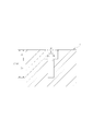
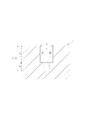
- FIG. 2 is a sectional view taken along line II-II of a groove formed on the surface of the model toy of FIG. It is sectional drawing of the other example of a groove part. It is sectional drawing of the other example of a groove part. It is sectional drawing of the other example of a groove part.
- (A) is a perspective view of the sample in which the groove part was formed in the surface
- (B) is sectional drawing of the sample of the figure (A).
- A) is a perspective view of the other sample in which the groove part was formed in the surface
- (B) is sectional drawing of the sample of the figure (A).
- FIG. 1 shows an example of a model toy for explaining an embodiment of the present invention
- FIG. 2 shows a cross section of a groove formed on the surface of the model toy of FIG.
- a groove 2 characterizing the character of the model toy 1 is formed at the center of the surface of the face of the model toy 1.
- the groove part 2 gives a three-dimensional effect to the model toy 1 by generating a dark part on a part of the surface of the face part.
- the groove portion 2 includes a first portion 2A extending in the depth direction of the groove portion 2 from the opening of the groove portion 2, and a tip (lower end) of the first portion 2A to the bottom of the groove portion 2 along the depth direction.
- the second portion 2B extends.
- the groove width of the second portion 2B is equal to or less than the groove width at the tip of the first portion 2A over the entire length in the depth direction of the groove portion 2, and the groove width at the tip (lower end) of the second portion 2B is: It is smaller than the groove width at the tip of the first portion 2A.
- the groove width of the second portion 2B of the groove portion 2 gradually decreases toward the tip of the second portion 2B, and the contour of the second portion 2B in the cross section orthogonal to the extending direction of the groove portion 2 is It is V-shaped.
- the illumination light that has entered the groove is reflected by the bottom surface of the groove, and this reflected light leaks again through the opening of the groove, but according to the groove 2 having the above configuration, only from the first portion 2A.
- the reflection in the groove portion 2 is repeated, and the reflection is attenuated by repeating the reflection, and leakage of the reflected light is suppressed.
- regions other than a groove part can be emphasized, and the three-dimensional effect of a model toy can be improved.
- the depth (D) from the opening of the groove portion 2 to the bottom of the groove portion 2 is larger than the width (W) at the opening of the groove portion 2, whereby the groove portion is reflected on the inner surface of the groove portion 2.
- the reflected light leaking out of 2 can be further reduced.
- the outline of the second portion 2B of the groove portion 2 is V-shaped, but the groove width of the second portion 2B of the groove portion 2 is gradually reduced toward the tip of the second portion 2B.
- the outline of the second portion 2B in the cross section orthogonal to the extending direction of the groove 2 may be U-shaped.
- the groove width of the second portion 2B of the groove portion 2 is smaller than the groove width at the tip of the first portion 2A of the groove portion 2 over the entire length in the depth direction of the groove portion 2 and It may be constant.
- the depth (Db) of the second portion 2B may be equal to or greater than the depth (Da) of the first portion 2A as shown in FIG. 4 (Db ⁇ Da), as shown in FIG. It may be less than the depth (Da) of the first portion 2A (Db ⁇ Da).
- the depth (D) from the opening of the groove part 2 to the bottom of the groove part 2 is preferably larger than the width (W) at the opening of the groove part 2 as in the example of FIGS.
- the sample of FIG. 6 is obtained by forming ten grooves A to J on a resin plate having a flat surface, and the sample of FIG. 7 has ten pieces of resin on a plate made of resin having an arcuate surface. Groove portions A to J are formed. 6 and FIG. 7, the shape of the groove portion is the groove portions C and H in FIG. 2, the groove portions B and G in FIG. 3, the groove portions D and I in FIG. 4, and the groove portions E and J in the groove portion 2 in FIG. 5. Each corresponds.
- the narrow groove portions B, C, D, and E arranged on the left side of FIGS. 6 and 7 have a width (W) at the opening of 0.2 mm, a depth (D) from the opening to the bottom of 0.4 mm, The depth (Da) of the first portion 2A is 0.3 mm.
- the wide groove portions G, H, I, and J arranged on the right side of FIGS. 6 and 7 have a width (W) at the opening of 0.4 mm, a depth (D) from the opening to the bottom of 0.8 mm, The depth (Da) of the first portion 2A is 0.6 mm.
- the angle ( ⁇ ) formed by the V-shaped contour of the second portion 2B in the cross section orthogonal to the extending direction is 90 °.
- the depth Da of the first portion 2A is desirably 1.5 times or more the width W of the opening.
- the groove portions A and F have the same width (W) at the opening and the depth (D) from the opening to the bottom, and the groove width is constant over the entire length from the opening to the bottom.
- the width (W) and depth (D) of the groove portion A are each 0.2 mm, and the width (W) and depth (D) of the groove portion F are each 0.4 mm.
- FIG. 8 is a photograph showing how the groove portions A to J of the sample of FIG. 6 are seen
- FIG. 9 is a photograph showing how the groove portions A to J of the sample of FIG. 7 are seen.
- the three-dimensional effect of the model toy can be enhanced without performing additional processing such as inking.
Landscapes
- Toys (AREA)
Abstract
【課題】墨入れによらず模型玩具の立体感を高める。 【解決手段】模型玩具1は、表面に形成された溝部2を備え、溝部2は、溝部2の開口から溝部2の深さ方向に延びる第1部分2Aと、第1部分2Aの先端から深さ方向に溝部2の底まで延びる第2部分2Bとからなり、第2部分2Bの溝幅は、深さ方向の全長に亘って第1部分2Aの先端における溝幅以下であり、且つ第2部分2Bの先端における溝幅は、第1部分2Aの先端における溝幅よりも小さい。
Description
本発明は、模型玩具に関する。
模型玩具では、陰影を表現するための溝部が表面に形成されることによって立体感が高められている。例えば、特許文献1に記載された模型玩具では、凹形状にて形成される凹空間と、凹空間に備えられて上方からの照射光の挿し込みを制限する狭小開口部と、凹空間の底部で照射光の差し込みに曝される位置に配置された強調範囲と、凹空間の底部で強調範囲より深く形成されて光の到達を抑制された暗部範囲とを備え、強調範囲と暗部範囲とのコントラストによって立体感が高められている。
陰影を強調して立体感をさらに高める目的で、黒色のマーカー等によって溝部が着色される所謂「墨入れ」が模型玩具に施される場合がある。しかし、例えば開口部が狭小な凹空間の底部など、溝部が形成されている箇所によっては墨入れが困難となる。
本発明は、墨入れによらず模型玩具の立体感を高めることを目的とする。
本発明に係る模型玩具は、表面に形成された溝部を備え、前記溝部は、前記溝部の開口から前記溝部の深さ方向に延びる第1部分と、前記第1部分の先端から前記深さ方向に前記溝部の底まで延びる第2部分とからなり、前記第2部分の溝幅は、前記深さ方向の全長に亘って前記第1部分の先端における溝幅以下であり、且つ前記第2部分の先端における溝幅は、前記第1部分の先端における溝幅よりも小さいことを特徴とする。
また、本発明に係る模型玩具においては、前記第2部分の溝幅が、前記第2部分の先端に向けて漸減していてもよい。
また、本発明に係る模型玩具においては、前記溝部の延在方向に直交する断面における前記第2部分の輪郭がV字状であってもよい。
また、本発明に係る模型玩具においては、前記溝部の延在方向に直交する断面における前記第2部分の輪郭がU字状であってもよい。
また、本発明に係る模型玩具においては、前記第2部分の溝幅が、前記深さ方向の全長に亘って前記第1部分の先端における溝幅よりも小さく且つ一定であってもよい。
また、本発明に係る模型玩具においては、前記第2部分の深さが、前記第1部分の深さ以上であってもよい。
また、本発明に係る模型玩具においては、前記第2部分の深さが、前記第1部分の深さ未満であってもよい。
また、本発明に係る模型玩具においては、前記溝部の深さが、前記溝部の前記開口における幅よりも大きくてもよい。
本発明によれば、墨入れによらず模型玩具の立体感を高めることができる。
図1は、本発明の実施形態を説明するための、模型玩具の一例を示し、図2は、図1の模型玩具の表面に形成された溝部の断面を示す。
図1のように、模型玩具1の顔部の表面中央には、模型玩具1のキャラクタを特徴付ける溝部2が形成されている。溝部2は、顔部の表面の一部に暗部を生じさせることにより、模型玩具1に立体感を付与する。
図2のように、溝部2は、溝部2の開口から溝部2の深さ方向に延びる第1部分2Aと、第1部分2Aの先端(下端)から深さ方向に沿って溝部2の底まで延びる第2部分2Bとからなる。
そして、第2部分2Bの溝幅は、溝部2の深さ方向の全長に亘って第1部分2Aの先端における溝幅以下であり、且つ第2部分2Bの先端(下端)における溝幅は、第1部分2Aの先端における溝幅よりも小さい。図2の例では、溝部2の第2部分2Bの溝幅は、第2部分2Bの先端に向けて漸減しており、溝部2の延在方向に直交する断面における第2部分2Bの輪郭はV字状となっている。
溝部内に射し込んだ照明光は溝部の底面で反射され、この反射光は再び溝部の開口を経て外に漏出するが、以上の構成を備える溝部2によれば、第1部分2Aのみからなる断面矩形状の単純な溝に比べ、溝部2内での反射が繰り返され、反射が繰り返されることによって反射光が減衰され、反射光の漏出が抑制される。これにより、暗部としての溝部2と溝部以外の領域とのコントラストを強調して模型玩具の立体感を高めることができる。
好ましくは、溝部2の開口から溝部2の底までの深さ(D)は、溝部2の開口における幅(W)よりも大きく、このようにすることにより、溝部2の内面で反射して溝部2の外に漏出する反射光をより減少させることができる。
なお、図2の例では、溝部2の第2部分2Bの輪郭はV字状であるが、溝部2の第2部分2Bの溝幅が第2部分2Bの先端に向けて漸減するものとして、図3のように、溝部2の延在方向に直交する断面における第2部分2Bの輪郭はU字状であってもよい。
また、図4及び図5のように、溝部2の第2部分2Bの溝幅は、溝部2の深さ方向の全長に亘って溝部2の第1部分2Aの先端における溝幅よりも小さく且つ一定であってもよい。この場合に、第2部分2Bの深さ(Db)は、図4のように、第1部分2Aの深さ(Da)以上であってもよく(Db≧Da)、図5のように、第1部分2Aの深さ(Da)未満であってもよい(Db<Da)。この場合にも、図2及び図3の例と同様、溝部2の開口から溝部2の底までの深さ(D)は、溝部2の開口における幅(W)よりも大きいことが好ましい。
次に、本発明の効果を確認するために行った実験例について説明する。
図6のサンプルは、平坦な表面を有する樹脂製の板材に10本の溝部A~Jを形成したものであり、図7のサンプルは、円弧上の表面を有する樹脂製の板材に10本の溝部A~Jを形成したものである。図6及び図7の各サンプルにおいて、溝部の形状は、溝部C、Hが図2、溝部B、Gが図3、溝部D、Iが図4、溝部E、Jが図5の溝部2にそれぞれ対応している。
図6及び図7の左側に配置された幅の狭い溝部B、C、D、Eは、開口における幅(W)が0.2mm、開口から底までの深さ(D)が0.4mm、第1部分2Aの深さ(Da)が0.3mmである。図6及び図7の右側に配置された幅の広い溝部G、H、I、Jは、開口における幅(W)が0.4mm、開口から底までの深さ(D)が0.8mm、第1部分2Aの深さ(Da)が0.6mmである。また、図2の溝部2に対応する溝部C、Hは、延在方向に直交する断面における第2部分2BのV字状の輪郭がなす角(θ)を90°とした。このように、第1部分2Aの深さDaは、開口における幅Wの1.5倍以上とすることが望ましい。
溝部A、Fは、開口における幅(W)と開口から底までの深さ(D)とが同一であり、且つ溝幅は、開口から底までの全長に亘って一定となっている。溝部Aの幅(W)及び深さ(D)はそれぞれ0.2mmであり、溝部Fの幅(W)及び深さ(D)はそれぞれ0.4mmである。
図8は図6のサンプルの溝部A~Jの見え方を示す写真であり、図9は図7のサンプルの溝部A~Jの見え方を示す写真である。
これらの写真から、図6のサンプル及び図7のサンプルのいずれにおいても、図2~図5に対応する形状を備えた溝部B~E、G~Jは、溝部A、Fと比較したとき、溝部以外の領域との明暗のコントラストが強くなっており、サンプルの立体感がより一層高められていることが分かる。また、実施形態の図2に対応する形状を備えた溝部C、Hにおいて特にコントラストが強くなることも判明した。
以上のように、本発明によれば、墨入れ等の付加的な処理を施すことなく模型玩具の立体感を高めることができる。
1 模型玩具
2 溝部
2A 第1部分
2B 第2部分
2 溝部
2A 第1部分
2B 第2部分
Claims (8)
- 表面に形成された溝部を備え、
前記溝部は、前記溝部の開口から前記溝部の深さ方向に延びる第1部分と、前記第1部分の先端から前記深さ方向に前記溝部の底まで延びる第2部分とからなり、
前記第2部分の溝幅は、前記深さ方向の全長に亘って前記第1部分の先端における溝幅以下であり、且つ前記第2部分の先端における溝幅は、前記第1部分の先端における溝幅よりも小さい模型玩具。 - 請求項1記載の模型玩具であって、
前記第2部分の溝幅は、前記第2部分の先端に向けて漸減している模型玩具。 - 請求項2記載の模型玩具であって、
前記溝部の延在方向に直交する断面における前記第2部分の輪郭はV字状である模型玩具。 - 請求項2記載の模型玩具であって、
前記溝部の延在方向に直交する断面における前記第2部分の輪郭はU字状である模型玩具。 - 請求項1記載の模型玩具であって、
前記第2部分の溝幅は、前記深さ方向の全長に亘って前記第1部分の先端における溝幅よりも小さく且つ一定である模型玩具。 - 請求項5記載の模型玩具であって、
前記第2部分の深さは、前記第1部分の深さ以上である模型玩具。 - 請求項5記載の模型玩具であって、
前記第2部分の深さは、前記第1部分の深さ未満である模型玩具。 - 請求項1から7のいずれか一項記載の模型玩具であって、
前記溝部の深さは、前記溝部の前記開口における幅よりも大きい模型玩具。
Priority Applications (1)
| Application Number | Priority Date | Filing Date | Title |
|---|---|---|---|
| CN201780058490.2A CN109715256B (zh) | 2016-11-30 | 2017-09-27 | 模型玩具 |
Applications Claiming Priority (2)
| Application Number | Priority Date | Filing Date | Title |
|---|---|---|---|
| JP2016-232185 | 2016-11-30 | ||
| JP2016232185A JP6220036B1 (ja) | 2016-11-30 | 2016-11-30 | 模型玩具 |
Publications (1)
| Publication Number | Publication Date |
|---|---|
| WO2018100858A1 true WO2018100858A1 (ja) | 2018-06-07 |
Family
ID=60156780
Family Applications (1)
| Application Number | Title | Priority Date | Filing Date |
|---|---|---|---|
| PCT/JP2017/035039 Ceased WO2018100858A1 (ja) | 2016-11-30 | 2017-09-27 | 模型玩具 |
Country Status (3)
| Country | Link |
|---|---|
| JP (1) | JP6220036B1 (ja) |
| CN (1) | CN109715256B (ja) |
| WO (1) | WO2018100858A1 (ja) |
Citations (2)
| Publication number | Priority date | Publication date | Assignee | Title |
|---|---|---|---|---|
| JP3171440U (ja) * | 2011-06-10 | 2011-11-04 | 株式会社バンダイ | 模型玩具 |
| US20140065927A1 (en) * | 2012-08-31 | 2014-03-06 | Samuel Yuehli Su | Weighted scale model vehicle |
Family Cites Families (22)
| Publication number | Priority date | Publication date | Assignee | Title |
|---|---|---|---|---|
| JPH077848B2 (ja) * | 1987-04-14 | 1995-01-30 | 日本電気株式会社 | 端面発光型発光ダイオ−ド |
| CN2032632U (zh) * | 1988-02-11 | 1989-02-15 | 马洪 | 一种装饰面砖 |
| CN2098051U (zh) * | 1991-06-28 | 1992-03-04 | 郭启寅 | 背面投影屏幕 |
| JP3077547B2 (ja) * | 1995-02-16 | 2000-08-14 | 日本鋼管株式会社 | 狭開先のルートギャップ幅検出方法 |
| US6253815B1 (en) * | 1998-08-14 | 2001-07-03 | Michelin Recherche Et Techniques S.A. | Design pattern for a tire |
| CN1241253C (zh) * | 2002-06-24 | 2006-02-08 | 丰田合成株式会社 | 半导体元件的制造方法 |
| CN2880204Y (zh) * | 2005-12-31 | 2007-03-21 | 安波 | 一种发光蜘蛛网 |
| KR100815763B1 (ko) * | 2006-10-13 | 2008-03-20 | 삼성에스디아이 주식회사 | 마스크 프레임 및 이를 이용한 마스크 프레임과 마스크의정렬방법 |
| JP2008201384A (ja) * | 2007-02-22 | 2008-09-04 | Toyo Tire & Rubber Co Ltd | 空気入りタイヤ |
| HRP20070339B1 (en) * | 2007-07-30 | 2010-08-31 | Sveu�ili�te u Zagrebu | Three dimensional puzzle |
| CN101655286A (zh) * | 2008-08-20 | 2010-02-24 | 刘玉山 | 腔式太阳能集热器 |
| CN101900432B (zh) * | 2009-05-29 | 2017-05-17 | 北京智慧剑科技发展有限责任公司 | 一种槽式黑体太阳能光热转化器 |
| JP6129079B2 (ja) * | 2011-12-06 | 2017-05-17 | 株式会社ダイカン | 意匠性発光装置および透光部材 |
| FR3007324B1 (fr) * | 2013-06-20 | 2015-07-17 | Michelin & Cie | Pneumatique comportant un marquage a fort contraste |
| FR3007325B1 (fr) * | 2013-06-21 | 2016-02-12 | Michelin & Cie | Pneumatique comportant un marquage a fort contraste |
| FR3009522B1 (fr) * | 2013-08-07 | 2016-12-23 | Michelin & Cie | Pneumatique comportant sur un flanc une texture particuliere |
| FR3009521B1 (fr) * | 2013-08-07 | 2015-08-14 | Michelin & Cie | Pneumatique comportant un element graphique particulier |
| FR3014365B1 (fr) * | 2013-12-11 | 2017-01-13 | Michelin & Cie | Pneumatique comportant un element graphique particulier |
| FR3018224B1 (fr) * | 2014-03-10 | 2017-11-17 | Michelin & Cie | Pneumatique comportant une texture a fort contraste sur la surface de roulement |
| FR3020594B1 (fr) * | 2014-04-30 | 2018-01-05 | Compagnie Generale Des Etablissements Michelin | Pneumatique comportant un symbole matriciel a fort contraste sur le flanc |
| CN104192068A (zh) * | 2014-06-18 | 2014-12-10 | 华东交通大学 | 具有自清洁效应的织构化镜面 |
| CN105270102B (zh) * | 2015-11-04 | 2018-04-03 | 江苏大学 | 一种基于仿生非光滑结构的轮胎花纹及高性能子午线轿车轮胎 |
-
2016
- 2016-11-30 JP JP2016232185A patent/JP6220036B1/ja active Active
-
2017
- 2017-09-27 WO PCT/JP2017/035039 patent/WO2018100858A1/ja not_active Ceased
- 2017-09-27 CN CN201780058490.2A patent/CN109715256B/zh active Active
Patent Citations (2)
| Publication number | Priority date | Publication date | Assignee | Title |
|---|---|---|---|---|
| JP3171440U (ja) * | 2011-06-10 | 2011-11-04 | 株式会社バンダイ | 模型玩具 |
| US20140065927A1 (en) * | 2012-08-31 | 2014-03-06 | Samuel Yuehli Su | Weighted scale model vehicle |
Non-Patent Citations (5)
| Title |
|---|
| "#16 Mold Horikomichu 1, Ayasan no Cross Cub Nikki", MG DESTINY GUNDAM SEISAKUKI, 2 May 2008 (2008-05-02), Retrieved from the Internet <URL:http://www.asayan.tk/?p=4191> [retrieved on 20170426] * |
| "Bandai 1/144 HGUC Gelgoog Marine Seisakuhen", MOKEI NO SHASHIN 1, 10 July 2016 (2016-07-10), Retrieved from the Internet <URL:https://web.archive.org/web/20161007124938/http://www.geocities.jp/xnkgg033/gerugugul.html> [retrieved on 20170426] * |
| "Dai 79 Kai Gussuma Gokin Series 01 'Tachikoma", MISOJI KOSHO NO BETSU NO KAO, 24 June 2008 (2008-06-24), Retrieved from the Internet <URL:http://misojikousyou.cocolog-bs.com/maniamisoji/2008/06> [retrieved on 20170426] * |
| "Ganpura Seisaku no Tejun·Technique·Osusume no Dogu Oshiemasu", AWASEME O MEDATANAKU SASERU 2-TSU NO HOHO, 15 October 2016 (2016-10-15), Retrieved from the Internet <URL:https://web.archive.org/web/20161015131953/http://howto-gunpla.com/assembly-5-3> [retrieved on 20170426] * |
| JOHANSHIN·TAIKANHEN, HGUC REVIEW GOUF SAKUSEN KAIGIYO KUMITATE REVIEW, 18 April 2016 (2016-04-18), Retrieved from the Internet <URL:http://blog.56doc.net/Entry/815> [retrieved on 20170426] * |
Also Published As
| Publication number | Publication date |
|---|---|
| JP6220036B1 (ja) | 2017-10-25 |
| CN109715256A (zh) | 2019-05-03 |
| JP2018086212A (ja) | 2018-06-07 |
| CN109715256B (zh) | 2022-02-11 |
Similar Documents
| Publication | Publication Date | Title |
|---|---|---|
| USD712975S1 (en) | Gaming machine | |
| USD900246S1 (en) | Toy building panel | |
| JP6347951B2 (ja) | 高コントラストのマークを備えた外科器具および外科器具をマークする方法 | |
| WO2015141439A1 (ja) | 組立構造体 | |
| TW201515858A (zh) | 電子裝置外殼及其採用之立體圖案結構 | |
| JP2019075283A (ja) | グリルイルミネーション | |
| JP2018089353A (ja) | 模型玩具 | |
| JP6220036B1 (ja) | 模型玩具 | |
| USD934175S1 (en) | Electrical connector | |
| JP6713739B2 (ja) | スパンドレル及び外装工法 | |
| USD966808S1 (en) | Gas burner | |
| CN102698439B (zh) | 模型玩具 | |
| USD924173S1 (en) | Fiber optic fanout kit | |
| KR102063256B1 (ko) | 채널형 간판 조립체 | |
| US9390638B2 (en) | Article with translucent ornamentation | |
| JP2006202700A (ja) | 樹脂パネル | |
| CN223199688U (zh) | 一种具有装饰功能的复合板 | |
| CN204829573U (zh) | 氛围灯 | |
| JP2016135943A (ja) | パネル体及び建築構成体 | |
| CN103807636A (zh) | 平面照明灯具 | |
| USD1013388S1 (en) | Toothbrush | |
| EP3486720A1 (en) | Projection lamp | |
| US20160312468A1 (en) | Inorganic translucent material | |
| USD842687S1 (en) | Anti-kink grommet | |
| TWI543409B (zh) | Wide-angle lighting of the LED lights |
Legal Events
| Date | Code | Title | Description |
|---|---|---|---|
| 121 | Ep: the epo has been informed by wipo that ep was designated in this application |
Ref document number: 17875434 Country of ref document: EP Kind code of ref document: A1 |
|
| NENP | Non-entry into the national phase |
Ref country code: DE |
|
| 122 | Ep: pct application non-entry in european phase |
Ref document number: 17875434 Country of ref document: EP Kind code of ref document: A1 |