WO2018097211A1 - 画像復元装置、方法、及びプログラム - Google Patents
画像復元装置、方法、及びプログラム Download PDFInfo
- Publication number
- WO2018097211A1 WO2018097211A1 PCT/JP2017/042106 JP2017042106W WO2018097211A1 WO 2018097211 A1 WO2018097211 A1 WO 2018097211A1 JP 2017042106 W JP2017042106 W JP 2017042106W WO 2018097211 A1 WO2018097211 A1 WO 2018097211A1
- Authority
- WO
- WIPO (PCT)
- Prior art keywords
- state
- image information
- observation
- pixel
- image
- Prior art date
- Legal status (The legal status is an assumption and is not a legal conclusion. Google has not performed a legal analysis and makes no representation as to the accuracy of the status listed.)
- Ceased
Links
Images







Classifications
-
- G—PHYSICS
- G06—COMPUTING OR CALCULATING; COUNTING
- G06T—IMAGE DATA PROCESSING OR GENERATION, IN GENERAL
- G06T7/00—Image analysis
- G06T7/40—Analysis of texture
- G06T7/41—Analysis of texture based on statistical description of texture
-
- G—PHYSICS
- G06—COMPUTING OR CALCULATING; COUNTING
- G06T—IMAGE DATA PROCESSING OR GENERATION, IN GENERAL
- G06T5/00—Image enhancement or restoration
-
- G—PHYSICS
- G06—COMPUTING OR CALCULATING; COUNTING
- G06T—IMAGE DATA PROCESSING OR GENERATION, IN GENERAL
- G06T7/00—Image analysis
- G06T7/90—Determination of colour characteristics
-
- H—ELECTRICITY
- H04—ELECTRIC COMMUNICATION TECHNIQUE
- H04N—PICTORIAL COMMUNICATION, e.g. TELEVISION
- H04N1/00—Scanning, transmission or reproduction of documents or the like, e.g. facsimile transmission; Details thereof
- H04N1/40—Picture signal circuits
- H04N1/407—Control or modification of tonal gradation or of extreme levels, e.g. background level
- H04N1/4072—Control or modification of tonal gradation or of extreme levels, e.g. background level dependent on the contents of the original
-
- H—ELECTRICITY
- H04—ELECTRIC COMMUNICATION TECHNIQUE
- H04N—PICTORIAL COMMUNICATION, e.g. TELEVISION
- H04N1/00—Scanning, transmission or reproduction of documents or the like, e.g. facsimile transmission; Details thereof
- H04N1/46—Colour picture communication systems
- H04N1/56—Processing of colour picture signals
- H04N1/60—Colour correction or control
- H04N1/6027—Correction or control of colour gradation or colour contrast
Definitions
- the present invention relates to an image restoration apparatus, method, and program.
- the present invention relates to a character recognition device that recognizes a document image sent from a facsimile, and a character recognition device that detects vertical line noise included in the document image and removes the noise has been proposed (for example, Patent Document 1). reference).
- This character recognition device detects vertical line noise characteristic of a document sent by facsimile from a document image, removes vertical line noise, and estimates that there is a character line segment in the part from which vertical line noise has been removed. Correct possible pixels to black pixels.
- a crease noise removing device that removes crease noise in the vertical and horizontal directions created in the original image based on the crease marks of the original paper has been proposed.
- a document is read, a binary document image is output, and a crease noise search having a predetermined width in the fold direction of the document image is performed at the position of a fold formed based on a predetermined folding method of the document sheet.
- Set the range Within this crease noise search range, run lengths of a predetermined length or more that connect pixels of a predetermined pixel value are integrated in the horizontal direction in the horizontal search range and in the vertical direction in the vertical search range, respectively.
- the rectangular area thus extracted is extracted, and predetermined pixels in the rectangular area are removed.
- Patent Documents 1 and 2 are intended for noise with a limited occurrence state such as vertical line noise and noise with a limited occurrence point such as crease noise.
- a limited occurrence state such as vertical line noise and noise with a limited occurrence point such as crease noise.
- it is desired to remove, as noise, uneven texture included in image information read by a scanner such as a document with wrinkles or irregular folds, or a document with gradation on the background.
- the color of the image and the color of the paper on which the document is printed and the background color are similar colors, the accuracy of character recognition for image information obtained by reading the document with a scanner may be reduced. For this reason, there are cases where it is desired to remove ground colors such as paper color and background color as noise, but this cannot be handled by the prior art.
- the present invention has been made in view of the above circumstances, and an object thereof is to provide an image restoration apparatus, method, and program capable of removing uneven texture and ground color included in image information. .
- an image restoration apparatus provides a drive source for original image information with respect to observation image information in which at least one of a non-uniform texture and ground color is mixed in the original image information.
- An image restoration apparatus for estimating the original image information from the observed image information using a prediction method based on a state space model included as a reference value calculated from a pixel value distribution of pixels included in the observed image information
- Determining means for determining whether each pixel of the observed image information is at least one of the non-uniform texture and the ground color based on the pixel value of each pixel included in the observed image information;
- the state quantity in the state n at the time n of the original image information is represented by the state quantity in the state (n-1) at the time (n-1), the state transition from the state (n-1) to the state n, And in the state (n-1)
- State quantity calculation means for calculating using the drive source including an element of the state quantity of the state n not included in the quantity, and
- the observation amount representing the process that becomes the observation image information is calculated using the state amount of the state n and the pixel value of the pixel determined by the determination means as at least one of the uneven texture and the ground color.
- the image restoration apparatus provides the original image information with respect to the observed image information in which at least one of uneven texture and ground color is mixed in the original image information.
- a prediction method based on a state space model included as a drive source, and an image restoration device that estimates the original image information from the observed image information, a reference value based on a pixel value of a pixel included in the observed image information, Determination means for determining whether each pixel of the observed image information is at least one of the non-uniform texture and the ground color based on a pixel value of each pixel included in the observed image information;
- the state quantity in the state n at the time n of the image information is the state quantity in the state (n-1) at the time (n-1), the state transition from the state (n-1) to the state n, and State quantity of state (n-1)
- a state quantity calculating means for calculating using the drive source including an element of the state quantity not included in the state n, and an observation image obtained by adding at least
- the observed image information is obtained by reading a document having images on both sides, and the non-uniform texture is formed on the surface having the original image information of the document on the other side. It is show-through image information in which an image is show-through, and the observation amount calculating means calculates the observation amount by multiplying the show-through image information by the nonlinear term and adding it to the original image information. it can.
- the observation amount calculation means can use the pixel value of the pixel determined as the non-uniform texture by the determination means as the show-through image information. Thereby, the original image from which the show-through image is removed can be restored only from the observation image information on the surface.
- the observation amount calculation means can use backside observation information obtained by reading the backside of the document as the show-through image information. Thereby, the show-through image can be removed with higher accuracy.
- the uneven texture is at least one of wrinkles and folds included in the image indicated by the observation image information, and gradation applied to the background of the image indicated by the observation image information.
- the observation amount calculation means can calculate the observation amount by multiplying texture image information indicating the non-uniform texture by the nonlinear term and adding the result to the original image information.
- the reference value is a value calculated from a distribution of pixel values of pixels included in the observed image information.
- An image restoration method is a state space model that includes the original image information as a drive source for observed image information in which at least one of a non-uniform texture and ground color is mixed in the original image information.
- the observation amount representing the process that becomes the observation image information is calculated using the state amount of the state n and the pixel value of the pixel determined by the determination means as at least one of the uneven texture and the ground color. Then, the estimation means uses the state quantity calculated by the state quantity calculation means and the observation quantity calculated by the observation quantity calculation means to predict the state quantity of the state n by the prediction method based on the state space model. Is the method of estimating the optimum value of the original image information as original image information.
- An image restoration method is a state space model that includes the original image information as a drive source for observed image information in which at least one of uneven texture and ground color is mixed in the original image information.
- the state quantity in the state n at the time n of the information is the state quantity in the state (n-1) at the time (n-1), the state transition from the state (n-1) to the state n, and the state Included in state quantity of (n-1)
- the observed amount calculation means adds the at least one of the non-uniform texture and the ground color to the original image information to obtain the observed image information.
- the amount of observation representing the process becomes the state quantity of the state n, the pixel value of the pixel determined by the determination means as at least one of the uneven texture and the ground color, and the original image information
- the state is calculated based on the state quantity calculated by the state quantity calculation means and the observation quantity calculated by the observation quantity calculation means, using a non-linear term representing the influence on the process. This is a method of estimating the optimum value of the state quantity of the state n as original image information by a prediction method based on a spatial model.
- the image restoration program according to the third invention is a program for causing a computer to function as each means constituting the image restoration device according to the first or second invention.
- FIG. 1 is a schematic configuration diagram of an image restoration apparatus according to first to fourth embodiments.
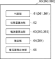
- FIG. 6 is a functional block diagram of an image restoration processing unit in the first to third embodiments.
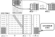
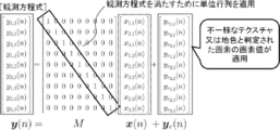
- 10 is a flowchart showing an example of image restoration processing in the first to third embodiments. It is a flowchart which shows an example of the determination process in 1st Embodiment. It is a figure for demonstrating the reference value of the determination process in 1st Embodiment. It is a figure for demonstrating the state space model in 1st Embodiment. It is a figure for demonstrating the state equation in 1st Embodiment. It is a figure for demonstrating the observation equation in 1st Embodiment.
- the uneven texture refers to a document in which paper is wrinkled or irregularly creased, a document with gradation on the background, or the like is read by a scanner to obtain image information.
- the image information indicates a wrinkle, a crease, a gradation or the like included in the image information.
- the ground color is a paper color or a background color printed on the paper.
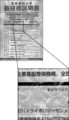
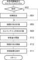
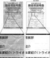
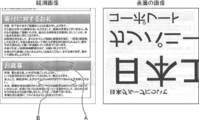
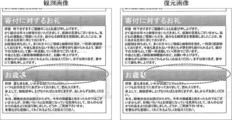
- FIG. 1 shows an example of an image including uneven texture and ground color, and an example of a partially enlarged view thereof. If such an uneven texture and ground color are included in the image, erroneous recognition is likely to occur when character recognition is performed on this image. It is desirable that only original image information indicating a necessary original image can be extracted. As described above, the present embodiment aims to remove the background color printed on the paper, and therefore the background color is not included in the original image among the images printed on the paper.
- the image restoration apparatus 10 is configured by a computer including a CPU, a ROM, a RAM, and an HDD, and as illustrated in FIG. 2, an input interface unit 20, an operation unit 30, and a storage unit 40.
- the image restoration processing unit 60 and the output interface unit 70 are provided.
- the input interface unit 20 performs input processing such as converting image information provided from the image input device into a data format that can be processed by a computer.
- the image input device is an input device for inputting image information (observation image information) to be processed into a computer as digital data.
- image information observation image information
- a case where the image input apparatus is a scanner will be described.
- the scanner reads a document on which a document is printed, and outputs the read image information as observation image information.
- the image input device is not limited to a scanner, and for example, a camera, a recording medium, a modem, or the like can be used.
- a camera means any device having an imaging function.
- a mobile phone equipped with a camera function a security camera (surveillance camera), a medical device for performing image diagnosis (internal view) Mirror, X-ray, echo, CT, MRI, etc.).
- Recording media widely mean recording media capable of recording image information.
- magnetic media HDD, FD, etc.
- optical discs CD, DVD, BD, etc.
- MO magneto-optical discs
- flash memory memory
- USB memory etc.
- the modem is a device for connecting to an external communication network (for example, a telephone line, a LAN, the Internet, etc.).
- the type of the image input device may be selected according to the use of the image restoration device 10.
- the input interface unit 20 is provided separately and independently according to the type of the image input device.
- the recording medium input interface unit 20 is also called a drive, and various types of drives can be used depending on the type of the recording medium.
- the drive is a device that reads and writes recording media.
- the input interface unit 20 and the output interface unit 70 are usually integrated.
- a modem can function as both an image input device and an image output device. Therefore, the input interface unit 20 and the output interface unit 70 are usually integrated with respect to the modem.
- the input interface unit 20 may be a built-in card (board) stored inside the computer main body, or may be an externally installed device connected via an internal interface unit (not shown).
- the corresponding input interface unit 20 includes a sampling unit and an A / D conversion unit (both not shown).
- the sampling unit samples the input analog signal at a predetermined sampling frequency and outputs the sampled analog signal to the A / D conversion unit.
- the sampling frequency can be changed according to the type of image to be restored.
- the A / D converter performs A / D conversion processing on the amplitude value of the sampled signal with a predetermined resolution.
- the operation unit 30 is, for example, a keyboard, a mouse, a touch panel, or the like, but a voice recognition device or the like may be used.
- Various parameters necessary for the image restoration processing in the present embodiment can be set by an input operation using the operation unit 30 by the user.
- the storage unit 40 is an element constituting the main body of the computer, and includes a main storage unit 41, an auxiliary storage unit 44, and a display memory 45.
- the main storage unit 41 includes a captured image memory 42 in which image information captured via the input interface unit 20 is stored, and a processing parameter memory 43 in which a program and various parameters for executing an image restoration process to be described later are stored. And have.
- the display memory 45 is an area in which image information indicating an image to be displayed on an image output device (not shown) configured by a display or the like is stored, and displays an observation image indicated by the captured image information (observation image information).
- the processing memory 47 that is a temporary storage area in the image restoration processing, and the restored image that has been restored.
- a restored image memory 48 in which image information after restoration processing (restored image information) is stored.
- the auxiliary storage unit 44 compensates for the capacity shortage of the main storage unit 41.
- the auxiliary storage unit 44 may be, for example, a hard disk (HD), a portable device such as a CD-ROM, DVD, SSD (Solid State Drive), flash memory, or the like. A combination thereof may also be used.
- the image restoration processing program is installed in the storage unit 40 from the recording medium via the input interface unit 20. Or downloaded to the storage unit 40 from the outside via the modem and input interface unit 20.
- the image restoration processing unit 60 is a processing unit for executing image restoration processing described later. Functionally, as shown in FIG. 3, the image restoration processing unit 60 includes a determination unit 61, a state quantity calculation unit 62, and an observation amount calculation unit. 63, an estimation unit 64, and a restored image output unit 65.
- the determination unit 61 compares the pixel value of each pixel included in the observation image with a reference value calculated from the histogram of the pixel value of each pixel included in the observation image, so that each pixel exhibits a non-uniform texture. It is determined whether the pixel is a pixel or a pixel indicating a ground color.
- the state quantity calculation unit 62 includes the state n at the time n in the observation image in the state transition from the state (n ⁇ 1) to the state n and the state (n ⁇ 1) at the time (n ⁇ 1). The calculation is performed using a chromatic color driving source constituted by elements of state n.
- the observation amount calculation unit 63 uses the pixel value of the pixel determined to be an uneven texture by the determination unit 61 or the pixel value determined to be the ground color. A process in which at least one of a non-uniform texture and a ground color is added to an image to form an observation image is calculated as an observation amount.
- the estimation unit 64 calculates a prediction method based on the state space model from the state quantity calculated by the state quantity calculation unit 62 and the observation quantity calculated by the observation quantity calculation unit 63 for the state n at the time n in the observed image. Used to estimate the optimal value of state n.
- the restored image output unit 65 uses the optimum value of the state n at the time n estimated by the estimation unit 64 as restored image information indicating a restored image obtained by restoring the original image by removing the uneven texture and ground color. And stored in the restored image memory 48.
- the output interface unit 70 converts the restored image information restored by the image restoration processing unit 60 and stored in the restored image memory 48 into a data format that can be output to an image output device configured by a display or the like, and performs output processing. I do.
- the output form of the processed image is not limited to the display on the image output apparatus, and may be output to another image output apparatus.
- a printer, a recording medium, a modem, or the like can be used as the image output device.
- the recording medium and the modem may be shared with the recording medium and the modem as the image input device, respectively.
- the type of the image output apparatus may be selected according to the use of the image restoration apparatus 10.
- the output interface unit 70 is provided independently according to the type of the image output device. As described above, regarding the recording medium and the modem, the input interface unit 20 and the output interface unit 70 are usually integrated. Similarly to the input interface unit 20, the output interface unit 70 may be a built-in card (board) stored inside the computer main body, or an externally installed device connected via the internal interface unit. Also good.
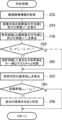
- the image restoration processing routine shown in FIG. 4 is stored as an image restoration program in the storage unit 40 and is executed by a CPU (not shown).
- step 100 observed image information obtained by reading a document on which a document is printed by a scanner which is an image input device is captured via the input interface unit 20, and is captured in the captured image memory 42 of the main storage unit 41.
- the acquired observation image information is also stored in the acquisition image memory 46 of the display memory 45, and the observation image is displayed on the image output device via the output interface unit 70.
- step 200 the determination unit 61 executes the determination process shown in FIG.
- step 202 of the determination process shown in FIG. 5 the determination unit 61 acquires observation image information from the captured image memory 42.
- step 204 the determination unit 61 creates a histogram of pixel values for each RGB component from the pixel values for each RGB component of each pixel included in the acquired observation image information.
- step 206 the determination unit 61 calculates, for each RGB component, a reference value y th for determining whether or not each pixel has a nonuniform texture or ground color based on the created histogram. .
- the pixel value of a pixel corresponding to an original image such as a character is a dark color (pixel value is small), and the pixel value of a pixel corresponding to a non-uniform texture, ground color, or the like. Is assumed to have a larger pixel value than characters. Therefore, if a pixel value for distinguishing between a small pixel value portion and a large pixel value portion is determined in the histogram, this pixel value can be used as the reference value y th . As a method for calculating such a reference value y th from the histogram, for example, the Otsu method can be used.
- the class of the pixel value from the 1st to the kth and the class of the pixel value from the k + 1 to the Lth K at which the inter-variance ⁇ 2 B is maximized is obtained as a threshold for class identification.
- the interclass variance ⁇ 2 B is expressed by the following equation (1). ⁇ (k) is the average of the pixel values included in the 1st to kth pixel value classes, and ⁇ (k) is the occurrence probability of the 1st to kth pixel value classes.
- the method for calculating the reference value y th from the histogram is not limited to the Otsu method described above.
- the median value between two peaks of the histogram, the median value between the bases of two peaks, or the like may be calculated as the reference value y th .
- a conventionally known method can be used as a method of detecting pixel values corresponding to peaks and skirts in the histogram.
- step 208 the determination unit 61 determines whether pixel values y m, or n is greater than the reference value y th.
- ym , n is the pixel value of the pixel (m, n) of the observation image
- (m, n) is the pixel position (pixel coordinate) in the horizontal and vertical directions of the observation image. If any of the RGB components satisfies y m, n > y th , the process proceeds to step 211, and the determination unit 61 determines that the pixel (m, n) is a pixel indicating an uneven texture, or It is determined that the pixel indicates the ground color, and the process returns to the image restoration processing routine (FIG. 4). On the other hand, for any component of RGB, if y m, n ⁇ y th , the process directly returns to the image restoration processing routine. Steps 208 and 211 are executed for each pixel for all pixels included in the observed image.
- the state quantity calculation unit 62 sets a common processing target area n (for example, a 3 ⁇ 3 pixel area) for the original image and the observed image. Then, in steps 400 to 600, calculation is performed using the state quantity calculated using only the original image information, the observed image information, the original image information, and the pixel values of the pixels determined to be uneven texture or ground color.
- a process for estimating the optimum value of the state quantity is executed by a Kalman algorithm with a colored drive source using a state space model including a colored drive source represented by the observed quantity.
- the observed image y i, j is represented by a state space model in which noise v i, j such as wrinkles, creases, gradations, ground colors, etc. is added to the original image x i, j .
- the state space model is expressed by the following equation (2) and the following equation (3).
- vector x (n) is a state vector (original image information) of state n at time n
- matrix ⁇ is a state transition matrix
- vector ⁇ (n) is a drive source vector.
- the vector y (n) is an observation vector (observation image information)
- the matrix M is an observation matrix
- the vector y v (n) is an observation noise vector.
- the state equation of equation (2) describes the system to be observed with a state space model, and generates internal states, that is, state variables (here, state vectors x (n ⁇ 1), x (n)). Represents the process.
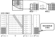
- the state vector x (n) is a vector having the pixel value of the original image included in the processing target area n as an element, and from the state (n ⁇ 1)
- the change to the state n is represented by a shift of a predetermined number of pixels in the predetermined direction of the processing target area n in the original image (one pixel in the right direction in the example of FIG. 8). Therefore, as shown in FIG. 8, the state transition matrix ⁇ has an action of extracting an element having the same system state quantity as the state vector x (n) from among the elements of the state vector x (n ⁇ 1).
- the drive source vector ⁇ (n) is composed of elements of the state vector x (n) that are not included in the state vector x (n ⁇ 1).
- the observation equation (3) describes the process of observation through some kind of observation device, and the observation result (here, the observation vector y (n)) is the observed quantity, that is, the input (here, The state is generated depending on the state vector x (n)).
- the first embodiment as described above, a process in which noise v i, j such as wrinkles, creases, gradations, ground colors, and the like is added to the original image x i, j to form the observed image y i, j is performed.
- the pixel value of the pixel determined by the determination unit 61 as an uneven texture or ground color is applied as the observation noise vector y v (n).
- the observation matrix M As the observation matrix M, a unit matrix for satisfying the observation equation is applied.
- the state quantity calculation unit 62 calculates the state quantity (state equation) of the state n at time n.
- the state quantity calculation unit 62 sets the state at time (n ⁇ 1) using the system state quantity of each pixel in the processing target area (n ⁇ 1) set at time (n ⁇ 1) as an element.
- a vector x (n ⁇ 1) and a state vector x (n) at time n having the system state quantity of each pixel in the processing target area n set at time n as an element are derived.
- the state quantity calculation unit 62 configures a state transition matrix ⁇ for extracting elements having the same system state quantity as the state vector x (n) from among the elements of the state vector x (n ⁇ 1).
- the state quantity calculation unit 62 configures the drive source vector ⁇ (n) with the elements of the state vector x (n) not included in the state vector x (n ⁇ 1).
- the state quantity calculation unit 62 calculates the state equation (2) using each vector and matrix.
- step 500 the observation amount calculation unit 63 calculates an observation amount (observation equation) at time n.
- the observation amount calculation unit 63 configures the observation vector y (n) with the pixel values of the pixels included in the processing target region n set in the observation image, and applies the unit matrix as the observation matrix M.
- the observation amount calculation unit 63 configures an observation noise vector y v (n) including elements corresponding to the pixels included in the processing target region n set in the observation image, and the pixels corresponding to the elements are determined by the determination unit. If it is determined by 61 that the texture or ground color is uneven, the pixel value of the pixel is set to the value of the corresponding element. The value of the element corresponding to is set to 0.
- the observation amount calculation unit 63 calculates the observation equation (3) using each vector and matrix.
- step 600 the estimation unit 64 uses the state quantity (state equation) calculated in step 400 and the observation quantity (observation equation) calculated in step 500 to perform the following Kalman with a colored drive source. Deriving the algorithm.
- step 602 the estimation unit 64 determines whether or not the Kalman algorithm is processed for the first time. If it is the first time, the process proceeds to step 604, and if it is the second time or later, the process proceeds to step 606.
- the estimation unit 64 performs initial setting. Specifically, the estimation unit 64 uses an initial value x ⁇ (0
- optimum estimated value vector an optimum estimated value of a state vector
- estimate error vector The initial value P (0
- step 606 the estimation unit 64 causes the state transition matrix ⁇ in the state space model defined in step 400, the initial value P (0
- step 608 the estimation unit 64 uses the correlation matrix P (n
- a Kalman gain matrix K (n) is calculated using the matrix R ⁇ (n) (same procedure 2).
- step 610 the estimation unit 64 is obtained in this step by the state transition matrix ⁇ and the initial value x ⁇ (0
- n) is calculated (same procedure 3).
- the estimation unit 64 uses the calculated optimum estimated value vector x ⁇ (n
- n) at that time based on the information up to time n is calculated (same procedure 4).
- step 612 the estimation unit 64 uses the unit matrix I, the Kalman gain matrix K (n), the observation matrix M, and the correlation matrix P (n
- step 614 the optimum estimated value vector x ⁇ (n
- the process returns to the image restoration processing routine (FIG. 4) and proceeds to step 700 to determine whether or not the image restoration processing has been completed for all areas of the original image. If the processing has not been completed for all the regions, the process returns to step 300 to set the next processing target region n and repeat the processing. When the processing is completed for all regions, the process proceeds to step 900, where the restored image output unit 65 outputs the image information stored in the restored image memory 48 via the output interface unit 70, and outputs the image. The restored image is displayed on the apparatus, and the image restoration process is terminated.
- each pixel of the observed image has a nonuniform texture. Whether or not each pixel is a ground color.
- the texture can also be determined with high accuracy.
- the reference value can be increased or decreased in the pixel value of the image.
- the pixel value of the entire image becomes low, and it is influenced by this, and the reference value is set to a lower pixel value.
- an original image portion such as a skin color is determined to be an uneven texture or background color, and the possibility of being removed is increased.
- the deterioration of the skin color part is an element that is easily visually recognized by humans, it greatly affects the image quality of the entire restored image.
- the non-uniform texture and ground color are added to the original image,
- the optimum value of the original image is estimated by the Kalman algorithm with a colored drive source based on the observation equation indicating the following process. Then, by using the estimated optimum value as a restored image obtained by restoring the original image, it is possible to remove the non-uniform texture and ground color from the observed image and restore the original image.
- An image restoration process by the image restoration apparatus 10 according to the first embodiment was performed on an observation image obtained by reading a document including wrinkles and ground colors as shown in FIG. Note that the document shown in FIG. 1 is actually a document in which some character portions and the background are printed in similar colors (green).
- An image restoration apparatus 210 is configured by a computer including a CPU, a ROM, a RAM, and an HDD. As illustrated in FIG. 2, the input interface unit 20, the operation unit 30, and the storage unit 40. The image restoration processing unit 260 and the output interface unit 70 are provided.
- the image restoration processing unit 260 functionally includes a determination unit 261, a state quantity calculation unit 62, an observation amount calculation unit 263, an estimation unit 264, and a restored image output unit 65. It can be expressed in a configuration that includes it.
- the determination unit 261 Based on the reference value using the dispersion value of the pixel value of the pixel included in the local region of the observation image and the pixel value of each pixel, the determination unit 261 shows the back image of the back surface of each pixel. It is determined whether or not the pixel indicates an image (show-through image).
- the show-through image is also an example of the uneven texture of the present invention.
- the observation amount calculation unit 263 adds the show-through image to the original image on the surface using the pixel value of the pixel determined as the pixel of the show-through image by the determination unit 261 based on the state n at the time n in the observation image. The process that becomes the observation image is calculated as the observation amount.
- the estimation unit 264 performs a prediction method based on the state space model from the state quantity calculated by the state quantity calculation unit 62 and the observation quantity calculated by the observation quantity calculation unit 263 for the state n at the time n in the observation image. Used to estimate the optimal value of state n.
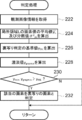
- the determination process shown in FIG. 12 is executed in step 200 of the image restoration process routine shown in FIG.
- step 222 of the determination process shown in FIG. 12 the determination unit 61 acquires observation image information from the captured image memory 42.
- the determination unit 261 determines, for each local region L (for example, a 3 ⁇ 3 pixel region) of the observation image, based on the pixel value for each RGB component of each pixel included in the local region L. for each RGB component, the average value ⁇ y L and the pixel value of the local region L, calculates the variance value sigma 2 yL shown below (4).
- M is the number of pixels in the horizontal direction of the local region L
- N is the number of pixels in the vertical direction of the local region L.
- the size of the local region L can be set to an arbitrary value according to the resolution of the observed image.
- step 226 the determination unit 261 determines that each pixel is obtained from the average value ⁇ y L and the variance value ⁇ 2 yL of the pixel values for each local region L of the observed image calculated for each RGB component in step 224.
- a reference value y thL for determining whether or not the pixel indicates a show-through image is calculated by the following equation (5).
- step 228, the determination unit 261 uses the pixel values y Rm, n , y Gm, n , y Bm, n for each RGB component of each pixel included in the local region L of the acquired observation image,
- the gray value y graym, n when the observed image is converted to gray scale is calculated by the following equation (6).
- step 230 determination unit 261, one of the pixel values y m of the components of the RGB of each pixel included in the local region L of the observed image (m, n), n and gray value y graym, n is It is determined whether or not both are larger than the reference value y thL . If any of the RGB components satisfies y m, n , y graym, n > y thL , the process proceeds to step 232, and the determination unit 261 indicates that the pixel (m, n) represents a show-through image. It returns to image restoration processing routine (FIG. 4).
- Steps 224 to 232 are executed for each local region L over the entire observation image.
- the state quantity calculation unit 62 sets a common processing target area n (for example, a 3 ⁇ 3 pixel area) for the original image and the observed image.
- steps 400 to 600 the state quantity calculated using only the original image information, and the observation image calculated using the observed image information, the original image information, and the pixel value of the pixel determined as the pixel indicating the show-through image.
- a process for estimating the optimum value of the state quantity is executed by a Kalman algorithm with a colored drive source using a state space model including a colored drive source represented by a quantity.
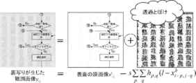
- the image on the back side shows through to the original image on the front side.
- the back image x b i-p, jq passes through the original image x f i, j on the front surface, and blurring occurs.
- This is represented by a state space model in which an image in a state where the occurrence is generated is superimposed.
- s is the transmittance
- hp q is a point spread function representing blur
- l is the maximum pixel value
- p is the number of pixels in the horizontal direction of the image
- q is the number of pixels in the vertical direction of the image. It is.
- (l ⁇ x b ip, jq ) is the pixel position (ip, jq) of the back side image x b corresponding to the pixel position (i, j) of the front side original image x f. )
- the transmittance through which the image on the back surface is transmitted depends on the thickness of the original, the density of the image, the illumination intensity at the time of scanning, and the like.
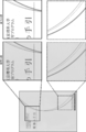
- the influence of the show-through image on the original image on the surface differs depending on the image information of the original image on the surface. For example, as shown in FIG. 14, the closer the original image on the surface is to black (the luminance value is 0), the less the influence of show-through (for example, the portion indicated by A in FIG. 14), The closer to (the luminance value is 255 on an 8-bit clay scale), the more susceptible to the show-through (for example, the portion indicated by B in FIG. 14). Therefore, if it is assumed that a fixed amount of show-through is added to the observed image regardless of the image information of the original image on the surface, the original image cannot be accurately restored.
- the state space model in the second embodiment can be expressed by the following equation (7).
- the non-linear term g (x fi , j ) is, for example, a surface image x fi , j having pixels with luminance values 0 to 255 in each row is printed on the surface, and has pixels with luminance values 0 to 255 in each column.
- the back image x b i, j can be derived from the following equation (8), which is a modification of the above equation (7), based on the observed image y f i, j obtained by reading the surface of the original printed on the back surface with a scanner ( Reference "F. Merrikh-Bayat, M. Babaie-Zadeh," A Nonlinear Blind Source Separation for Removing the Show-through Effect in the Scanned Documents ", European Signal Processing Conference-EUSIPCO, Aug. 2008”).
- g (x f i, j ) calculated from the above equation (8), the horizontal axis represents the luminance value of the surface image x f i, j , and the vertical axis represents g (x f i, j ) Is approximated as the following equation (9), and the following equation (10) obtained by performing the first-order Taylor expansion is used as the nonlinear term g (x f i, j ) of the state space model.
- g (x fi , j ) is not limited to this example, and may be a function that performs weighting representing the influence of show-through according to the image information on the surface as described above.
- the state equation is configured in the same manner as in the first embodiment. Since the state vector x (n) and the drive source vector ⁇ (n) have the pixel values of the original image on the surface as elements, in the second embodiment, x f (n) and ⁇ f (n) Is written.
- the above equation (11) is applied as shown in FIG. In the example of FIG. 16, the observation equation focuses on the pixel value y f 2,2 (n) of the target pixel (2, 2) in the observation image at time n.
- ⁇ M T ⁇ y v2,2 (n) c T ⁇ corresponding to (1-cy vm, n ) in the equation (11) corresponds to the observation matrix M in the first embodiment.
- the determination unit 261 causes the target pixel (2,2) to be a show- through image.
- the pixel value y f 2,2 (n) is applied.
- the target pixel (2, 2) is the center pixel of the processing target area n of 3 ⁇ 3 pixels, but is not limited to this example.
- the state quantity calculation unit 62 calculates the state quantity (state equation) of the state n at time n, as in the first embodiment. To do.
- the observation amount calculation unit 263 calculates an observation amount (observation equation) at time n.
- the observation amount calculation unit 263 determines the pixel of interest (2) for the observation equation of the pixel value y f 2,2 (n) of the pixel of interest (2, 2) of the processing target region n set in the observation image. , 2) is determined as a pixel indicating a show-through image, the pixel value y f v2,2 (n) is applied as it is, and the target pixel (2, 2) is not a pixel indicating a show-through image. In this case, y f v2,2 (n) is set to 0. Further, the observation amount calculation unit 263 calculates an observation equation of the pixel value y f 2,2 (n) using the unit vector m for configuring the term corresponding to the observation matrix and the vector c indicating the constant.
- step 600 the estimation unit 264 uses the state quantity (state equation) calculated in step 400 and the observation quantity (observation equation) calculated in step 500 to perform the following Kalman with a colored drive source. Deriving the algorithm.
- the Kalman algorithm with a colored drive source in the second embodiment differs from the Kalman algorithm with a colored drive source in the first embodiment in that a matrix shown in the following equation (12) is used instead of the observation matrix M Using m p , instead of the covariance matrix R ⁇ (n) of the observed noise vector, the point where the matrix r ⁇ (n) shown in the following equation (13) is used, and in the procedure 2, as the Kalman gain matrix, the matrix K The point is that the matrix k (n) is calculated instead of (n).
- the image restoration apparatus 210 when the front surface of a document on which images are printed on both sides is scanned, the image on the back surface shows through on the front surface.
- the state space model including the nonlinear term reflecting the influence of the original image information on the surface on the show-through is used, the original image information can be accurately restored.
- the removal target can be an uneven texture and ground color indicating wrinkles, irregular creases, and the like, as in the first embodiment.
- pixel values of pixels determined to be non-uniform texture or ground color may be used for yn2,2 of the observation equation.
- the removal target can be a show-through image as in the second embodiment.
- the pixel value of the pixel determined as the pixel indicating the show-through image may be used as the observation noise vector y v (n) of the observation equation.
- An image restoration apparatus 310 is configured by a computer including a CPU, a ROM, a RAM, and an HDD, and as illustrated in FIG. 2, an input interface unit 20, an operation unit 30, and a storage unit 40.
- the image restoration processing unit 360 and the output interface unit 70 are provided.
- the image restoration processing unit 360 functionally includes a determination unit 361, a state quantity calculation unit 62, an observation amount calculation unit 363, an estimation unit 264, and a restored image output unit 65. It can be expressed in a configuration that includes it.
- the determination unit 361 uses a process similar to that of the determination unit 261 in the second embodiment to generate a reference value using a pixel value variance value of pixels included in the local region of the observation image and a pixel value of each pixel. Based on this, it is determined whether each pixel is a pixel indicating a ground color.
- the observation amount calculation unit 363 uses the pixel value of the pixel determined as the pixel indicating the ground color by the determination unit 361 based on the state n at the time n in the observation image, and adds the ground color to the original image to observe the image. Is calculated as an observed quantity.
- an observed image y i, j obtained by scanning a document including a ground color is represented by a state space model in which a ground color v i, j is added to the original image x i, j. .
- the state space model in the third embodiment can be expressed by the following equation (14).
- the expression (10) can be applied as in the second embodiment.
- the expression (11) is derived from the expressions (14) and (10) as in the second embodiment. Therefore, the observation amount calculation unit 363 can calculate the observation amount (observation equation) at time n, similarly to the observation amount calculation unit 263 according to the second embodiment. At this time, when it is determined that the target pixel (2, 2) is a pixel indicating the ground color, the observation amount calculation unit 363 applies the pixel value y f v2,2 (n) as it is, and the target pixel (2 , 2) is not a pixel indicating the ground color, y f v2,2 (n) is set to 0.
- the Kalman algorithm with a colored drive source in the estimation unit 264 can be executed in the same manner as in the second embodiment.
- the image restoration apparatus 310 since the state space model including the nonlinear term reflecting the influence of the original image information on the ground color is used, the original image information is accurately processed. It can be restored well.
- FIG. 18 shows an example of the processing result of the image restoration apparatus 310 according to the third embodiment. As shown in FIG. 18, it can be seen that after the image restoration processing, the ground color is removed including the character portion and the line included in the original image.
- the image restoration apparatus accurately restores an original image even for an observation image in which uneven texture such as wrinkles, ground color, show-through, etc. are generated in a composite manner. can do.
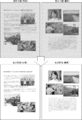
- FIG. 19 shows a processing result obtained by reading a manuscript (actually a color image) on which characters and photographs are printed on both sides, and performing restoration processing by the present technique on an observation image including a show-through and a ground color.
- a manuscript actually a color image
- restoration processing by the present technique on an observation image including a show-through and a ground color.
- FIG. 19 it can be seen that the show-through and ground color included in the observed image are removed from the restored image.
- image quality deterioration due to the effects of show-through and ground color removal is also suppressed in the skin color portion of a person. Since the deterioration of the skin color portion is an element that can be easily recognized visually by humans, the reproducibility of the skin color portion is good, so that the image quality of the entire restored image can be improved.
- FIG. 20 shows an example of a processing result obtained by reading a receipt and performing restoration processing by the present technique on an observation image including wrinkles and ground colors.
- FIG. 20 shows, as a comparative example, a restored image obtained by a conventional method that does not use a state space model including a nonlinear term. It can be seen that both the wrinkles and the ground color are removed with high accuracy in the restored image by this method compared to the conventional method. Note that, in the restoration processing of the processing result of FIG. 20 by the present method, an edge extraction filter is applied to the observation matrix in the observation equation to clarify the characters.
- this technique has high removal accuracy such as uneven texture such as wrinkles, ground color, and show-through, and thus tends to be wrinkled such as receipts as an example of the processing result shown in FIG.
- This is also effective for reading a document.
- the present invention when the present invention is applied to an application that scans a receipt and records the contents of the recognized receipt in the household account book, the original image (the contents of the receipt) can be accurately restored from a wrinkled receipt. Therefore, misrecognition of character recognition can be reduced.
- An image restoration apparatus 410 is configured by a computer including a CPU, a ROM, a RAM, and an HDD, and as illustrated in FIG. 2, the input interface unit 20, the operation unit 30, and the storage unit 40.
- the image restoration processing unit 460 and the output interface unit 70 are provided.
- the image restoration processing unit 460 functionally includes an alignment unit 461, a state amount calculation unit 62, an observation amount calculation unit 463, an estimation unit 464, and a restored image output unit 65.
- an alignment unit 461 a state amount calculation unit 62
- an observation amount calculation unit 463 a state amount calculation unit 62
- an estimation unit 464 a restored image output unit 65.
- the alignment unit 461 aligns corresponding pixels in the front-side observation image x fi , j and the back-side observation image x b i, j .
- the alignment unit 461 can perform alignment by a technique such as block matching, for example.
- information that can be used for alignment of the observed image x fi i, j on the front surface and the observed image x b i, j on the back surface is acquired, for example, when scanned by a scanner that scans the front surface and the back surface simultaneously. If possible, the alignment unit 461 may acquire the information and perform alignment.
- the observation amount calculation unit 463 calculates, as an observation amount, a process in which a show-through image is added to the original image on the front surface to form an observation image using the image information on the back surface based on the state n at the time n in the observation image.
- the estimation unit 464 performs a prediction method based on the state space model based on the state quantity calculated by the state quantity calculation unit 62 and the observation quantity calculated by the observation quantity calculation unit 463 for the state n at the time n in the observed image. Used to estimate the optimal value of state n.
- the image restoration processing routine shown in FIG. 22 is stored as an image restoration program in the storage unit 40 and is executed by a CPU (not shown).
- step 150 the input interface unit 20 obtains the observation image information on the front surface and the observation image information on the back surface obtained by reading each of the front surface and the back surface of the document on which both sides of the document are printed by the scanner which is an image input device. And stored in the captured image memory 42 of the main storage unit 41.
- the alignment unit 461 acquires the observation image information on the front and back surfaces from the captured image memory 42, and performs alignment between the front and back surfaces.
- the state space model in the fourth embodiment will be described. Similarly to the state space model in the second embodiment, the state space model in the fourth embodiment can be expressed by Expression (7). Then, by applying the nonlinear term shown in Expression (10) to Expression (7), the state space model shown in Expression (15) is derived.
- the state quantity calculation unit 62 calculates the state quantity (state equation) of the state n at time n as in the second embodiment. To do.
- step 550 the observation amount calculation unit 463 calculates an observation amount (observation equation) at time n.
- the observation amount calculation unit 463 corresponds to the observation matrix for the observation equation of the pixel value y f 2,2 (n) of the target pixel (2, 2) of the processing target region n set in the observation image.
- step 600 the estimation unit 264 uses the state quantity (state equation) calculated in step 400 and the observation quantity (observation equation) calculated in step 550, as in the second embodiment. Then, the Kalman algorithm with a colored driving source is derived.
- the Kalman algorithm with a colored drive source in the fourth embodiment a matrix m p shown in the following equation (18) and a matrix r ⁇ (n) shown in the following equation (19) are used.
- the image restoration device 410 in the state space model including the nonlinear term reflecting the influence of the original image information on the front surface on the show-through, the image information on the back surface is also included. Since the original image information is restored using the original image information, the original image information can be restored with higher accuracy.
- FIG. 23 shows an example of the processing result of the image restoration apparatus 410 according to the fourth embodiment. As shown in FIG. 23, it can be seen that after the image restoration process, the show-through overlapping with the image information on the surface is also removed.
- the processing target area is shifted by one pixel in the right direction as a change from the state (n ⁇ 1) to the state n
- the present invention is not limited to this.
- the processing target area may be shifted downward in the image.
- step 200 of FIG. 4 the case where the determination process shown in FIG. 5 is executed in the first embodiment and the determination process shown in FIG. 12 is executed in the second and third embodiments has been described.
- the determination process shown in FIG. 12 may be executed in the first embodiment, or the determination process shown in FIG. 5 may be executed in the second and third embodiments.
- the determination process is not limited to the examples shown in FIGS.
- the determination may be performed using a reference value calculated from the variance value of all pixels of the observation image.
- the determination process in this case will be described with reference to FIG.
- step 252 the determination unit acquires observation image information from the captured image memory 42.
- step 254 the determination unit calculates an average value ⁇ y of the pixel values of the entire observation image for each RGB component from the pixel values for each RGB component of each pixel included in the acquired observation image information. Then, using the average value ⁇ y calculated by the determination unit, the variance value ⁇ 2 y of the pixel values of the entire observation image is calculated for each RGB component by the above equation (4). At this time, the variance value ⁇ 2 yL in equation (4) is read as ⁇ 2 y , the average value ⁇ y L as ⁇ y, M as the number of pixels in the horizontal direction of the observation image, and N as the number of pixels in the vertical direction of the observation image. .
- the determination unit determines, for each local region L (for example, a 3 ⁇ 3 pixel region) of the observation image, based on the pixel value for each RGB component of each pixel included in the local region L. For each RGB component, the average value ⁇ y L and the variance value ⁇ 2 yL of the pixel values in the local region L are calculated. The variance value ⁇ 2 yL is calculated by the above equation (4).
- step 258 the determination unit determines that the average value ⁇ y L of the pixel values in the local region L is larger than the average value ⁇ y of the pixel values in the entire observation image and the variance value ⁇ 2 of the pixel values in the local region L. It is determined whether yL is larger than the variance value ⁇ 2 y of the pixel values of the entire observation image. If the determination is affirmative for any component of RGB, the process proceeds to step 260, and if the determination is negative for any component of RGB, the process proceeds to step 262.
- step 260 the determination unit determines that each pixel included in the corresponding local region L is a pixel indicating a non-uniform texture, and proceeds to step 262. Steps 256 to 260 are executed for each local region L over the entire observation image.
- step 262 the determination unit determines whether or not each pixel is a ground color from the average value ⁇ y and the variance value ⁇ 2 y of the pixel values of the entire observation image calculated for each RGB component in step 254.
- the reference value y th is calculated by the above equation (5).
- the variance value ⁇ 2 yL in equation (5) is read as ⁇ 2 y
- the average value ⁇ y L is read as ⁇ y.
- the determination unit determines each of the pixels included in the observed image (m, n) pixel values y m of, n is whether the reference value y th is greater than. If any component of RGB satisfies ym , n > yth, the process proceeds to step 266, where the determination unit determines that the pixel (m, n) is a pixel indicating the ground color, and the image Returning to the restoration processing routine (FIG. 4). On the other hand, for any component of RGB, if y m, n ⁇ y th , the process directly returns to the image restoration processing routine. The processing in steps 264 and 266 is executed for each pixel for all the pixels included in the observation image.
- observation image information is acquired by reading a document with a scanner.
- the present invention is not limited to this, and images taken in various fields may be used as observation images.
- a medical image or an image taken for inspection or inspection at a construction / civil engineering site may be used as the observation image.
- the present invention can be applied to real-time image analysis and the like in various fields such as the medical field, the construction / civil engineering field, and the like.
- each unit may be configured by hardware.
Landscapes
- Engineering & Computer Science (AREA)
- Physics & Mathematics (AREA)
- General Physics & Mathematics (AREA)
- Theoretical Computer Science (AREA)
- Computer Vision & Pattern Recognition (AREA)
- Probability & Statistics with Applications (AREA)
- Multimedia (AREA)
- Signal Processing (AREA)
- Image Processing (AREA)
- Image Analysis (AREA)
- Facsimile Image Signal Circuits (AREA)
Abstract
画像情報に含まれる不一様なテクスチャ及び地色を除去する。判定部(61)が、観測画像情報の画素値に基づく基準値と各画素の画素値とに基づいて、各画素が不一様なテクスチャ又は地色かを判定し、状態量算出部(62)が、原画像情報の状態nにおける状態量を、状態(n-1)の状態量、(n-1)からnへの状態遷移、及び駆動源を用いて算出し、観測量算出部(63)が、原画像情報に不一様なテクスチャ又は地色が加わって観測画像情報となる過程を表す観測量を、状態nの状態量、不一様なテクスチャ又は地色と判定された画素の画素値、及び原画像情報に応じてその過程に与える影響を表した非線形項を用いて算出し、推定部(64)が、有色性駆動源付カルマンアルゴリズムにより、算出された状態量及び観測量に基づいて、状態nの状態量の最適値を原画像情報として推定する。
Description
本発明は、画像復元装置、方法、及びプログラムに関する。
従来、画像工学の分野において、劣化した画像から原画像を復元する技術の研究開発が多くなされている。すなわち、原画像情報(所望の情報)に劣化情報(ぼけ、雑音、裏写り等)が混在した劣化画像情報(取得された情報)から劣化画像情報を取り除き、原画像を復元する技術が提案されている。
例えば、ファクシミリから送られてきた文書画像を認識する文字認識装置に関するもので、文書画像に含まれる縦ラインノイズを検出し、ノイズを除去する文字認識装置が提案されている(例えば、特許文献1参照)。この文字認識装置では、文書画像からファクシミリで送られてくる文書に特徴的な縦ラインノイズを検出し、縦ラインノイズを除去し、縦ラインノイズを除去した部分で文字の線分があると推定できる画素を黒画素に修正する。
また、例えば、原稿用紙の折り目跡に基づいて原稿画像に作成された縦及び横方向の折り目ノイズを除去する折り目ノイズ除去装置が提案されている。この折り目ノイズ除去装置では、原稿を読み取り、2値の原稿画像を出力し、原稿用紙の所定の折り畳み方に基づいて形成される折り目の位置に、原稿画像の折り目方向に所定幅の折り目ノイズ探索範囲を設定する。そして、この折り目ノイズ探索範囲内で、横方向の探索範囲においては水平方向に、縦方向の探索範囲においては垂直方向に、それぞれ所定画素値の画素が連結する所定長さ以上のランレングスを統合した矩形領域を抽出し、この矩形領域内の所定の画素を除去する。
しかしながら、特許文献1及び2に記載の技術では、縦ラインノイズのように発生状況が限られたノイズや、折り目ノイズのように発生箇所が限られたノイズを対象としている。そのため、従来技術では、例えば、シワや不規則な折り目が生じた文書や、背景にグラデーションが施されている文書などをスキャナで読み取った画像情報に含まれる不一様なテクスチャをノイズとして除去したい場合などには対応することができない。また、画像の色と、文書が印刷される用紙の色や背景色とが同系色の場合には、その文書をスキャナで読み取った画像情報に対する文字認識の精度が低下する場合がある。そのため、用紙の色や背景色などの地色をノイズとして除去したい場合もあるが、従来技術では対応することができない。
本発明は、上記事情に鑑みてなされたものであり、画像情報に含まれる不一様なテクスチャ及び地色を除去することができる画像復元装置、方法、及びプログラムを提供することを目的とする。
上記目的を達成するために、第1の発明に係る画像復元装置は、原画像情報に不一様なテクスチャ及び地色の少なくとも一方が混在した観測画像情報に対し、前記原画像情報を駆動源として含む状態空間モデルに基づく予測法を用い、前記観測画像情報から前記原画像情報を推定する画像復元装置であって、前記観測画像情報に含まれる画素の画素値の分布から算出される基準値と、前記観測画像情報に含まれる各画素の画素値とに基づいて、前記観測画像情報の各画素が前記不一様なテクスチャ及び前記地色の少なくとも一方か否かを判定する判定手段と、前記原画像情報の時刻nでの状態nにおける状態量を、時刻(n-1)での状態(n-1)の状態量、前記状態(n-1)から前記状態nへの状態遷移、及び前記状態(n-1)の状態量に含まれない前記状態nの状態量の要素を含む前記駆動源を用いて算出する状態量算出手段と、前記原画像情報に前記不一様なテクスチャ及び前記地色の少なくとも一方が加わって観測画像情報となる過程を表す観測量を、前記状態nの状態量、及び前記判定手段により前記不一様なテクスチャ及び前記地色の少なくとも一方と判定された画素の画素値を用いて算出する観測量算出手段と、前記状態量算出手段により算出された状態量、及び前記観測量算出手段により算出された観測量に基づいて、前記状態空間モデルに基づく予測法により、前記状態nの状態量の最適値を原画像情報として推定する推定手段と、を含んで構成されている。
これにより、画像情報に含まれる不一様なテクスチャ及び地色を除去することができる。
また、上記目的を達成するために、第2の発明に係る画像復元装置は、原画像情報に不一様なテクスチャ及び地色の少なくとも一方が混在した観測画像情報に対し、前記原画像情報を駆動源として含む状態空間モデルに基づく予測法を用い、前記観測画像情報から前記原画像情報を推定する画像復元装置であって、前記観測画像情報に含まれる画素の画素値に基づく基準値と、前記観測画像情報に含まれる各画素の画素値とに基づいて、前記観測画像情報の各画素が前記不一様なテクスチャ及び前記地色の少なくとも一方か否かを判定する判定手段と、前記原画像情報の時刻nでの状態nにおける状態量を、時刻(n-1)での状態(n-1)の状態量、前記状態(n-1)から前記状態nへの状態遷移、及び前記状態(n-1)の状態量に含まれない前記状態nの状態量の要素を含む前記駆動源を用いて算出する状態量算出手段と、前記原画像情報に前記不一様なテクスチャ及び前記地色の少なくとも一方が加わって観測画像情報となる過程を表す観測量を、前記状態nの状態量、前記判定手段により前記不一様なテクスチャ及び前記地色の少なくとも一方と判定された画素の画素値、及び前記原画像情報に応じて前記過程に与える影響を表した非線形項を用いて算出する観測量算出手段と、前記状態量算出手段により算出された状態量、及び前記観測量算出手段により算出された観測量に基づいて、前記状態空間モデルに基づく予測法により、前記状態nの状態量の最適値を原画像情報として推定する推定手段と、を含んで構成されている。
これにより、原画像情報に不一様なテクスチャ及び地色の少なくとも一方が加わって観測画像情報となる過程に与える原画像情報の影響を考慮することができるため、画像情報に含まれる不一様なテクスチャ及び地色を、より精度良く除去することができる。
また、第2の発明において、前記観測画像情報は、両面に画像を有する文書を読み取ることにより得られ、前記不一様なテクスチャは、前記文書の原画像情報を有する面に、他方の面の画像が裏写りした裏写り画像情報であり、前記観測量算出手段は、前記裏写り画像情報に前記非線形項を乗算して、前記原画像情報に加えることにより、前記観測量を算出することができる。これにより、原画像情報に裏写り画像情報が加わって観測画像情報となる過程に与える原画像情報の影響を考慮することができるため、画像情報に含まれる不一様なテクスチャ及び地色を、より精度良く除去することができる。
また、第2の発明において、前記観測量算出手段は、前記判定手段により前記不一様なテクスチャと判定された画素の画素値を、前記裏写り画像情報として用いることができる。これにより、表面の観測画像情報のみから、裏写り画像を除去した原画像を復元することができる。
また、第2の発明において、前記観測量算出手段は、前記文書の裏面を読み取ることにより得られた裏面観測情報を、前記裏写り画像情報として用いることができる。これにより、より精度良く裏写り画像を除去することができる。
また、第2の発明において、前記不一様なテクスチャは、前記観測画像情報が示す画像に含まれるシワ及び折り目、並びに前記観測画像情報が示す画像の背景に施されたグラデーションの少なくとも一つであり、前記観測量算出手段は、前記不一様なテクスチャを示すテクスチャ画像情報に前記非線形項を乗算して、前記原画像情報に加算することにより、前記観測量を算出することができる。これにより、原画像情報に不一様なテクスチャや地色が加わって観測画像情報となる過程に与える原画像情報の影響を考慮することができるため、画像情報に含まれる不一様なテクスチャ及び地色を、より精度良く除去することができる。
また、第2の発明において、前記基準値は、前記観測画像情報に含まれる画素の画素値の分布から算出される値である。これにより、不一様なテクスチャ及び地色の判定のための基準値の処理量を削減できると共に、肌色などの画像部分が不一様なテクスチャ及び地色と判定される誤判定を低減することができる。
また、第3の発明に係る画像復元方法は、原画像情報に不一様なテクスチャ及び地色の少なくとも一方が混在した観測画像情報に対し、前記原画像情報を駆動源として含む状態空間モデルに基づく予測法を用い、前記観測画像情報から前記原画像情報を推定する画像復元方法であって、判定手段が、前記観測画像情報に含まれる画素の画素値の分布から算出される基準値と、前記観測画像情報に含まれる各画素の画素値とに基づいて、前記観測画像情報の各画素が前記不一様なテクスチャ及び前記地色の少なくとも一方か否かを判定し、状態量算出手段が、前記原画像情報の時刻nでの状態nにおける状態量を、時刻(n-1)での状態(n-1)の状態量、前記状態(n-1)から前記状態nへの状態遷移、及び前記状態(n-1)の状態量に含まれない前記状態nの状態量の要素を含む前記駆動源を用いて算出し、観測量算出手段が、前記原画像情報に前記不一様なテクスチャ及び前記地色の少なくとも一方が加わって観測画像情報となる過程を表す観測量を、前記状態nの状態量、及び前記判定手段により前記不一様なテクスチャ及び前記地色の少なくとも一方と判定された画素の画素値を用いて算出し、推定手段が、前記状態量算出手段により算出された状態量、及び前記観測量算出手段により算出された観測量に基づいて、前記状態空間モデルに基づく予測法により、前記状態nの状態量の最適値を原画像情報として推定する方法である。
また、第4の発明に係る画像復元方法は、原画像情報に不一様なテクスチャ及び地色の少なくとも一方が混在した観測画像情報に対し、前記原画像情報を駆動源として含む状態空間モデルに基づく予測法を用い、前記観測画像情報から前記原画像情報を推定する画像復元方法であって、判定手段が、前記観測画像情報に含まれる画素の画素値に基づく基準値と、前記観測画像情報に含まれる各画素の画素値とに基づいて、前記観測画像情報の各画素が前記不一様なテクスチャ及び前記地色の少なくとも一方か否かを判定し、状態量算出手段が、前記原画像情報の時刻nでの状態nにおける状態量を、時刻(n-1)での状態(n-1)の状態量、前記状態(n-1)から前記状態nへの状態遷移、及び前記状態(n-1)の状態量に含まれない前記状態nの状態量の要素を含む前記駆動源を用いて算出し、観測量算出手段が、前記原画像情報に前記不一様なテクスチャ及び前記地色の少なくとも一方が加わって観測画像情報となる過程を表す観測量を、前記状態nの状態量、前記判定手段により前記不一様なテクスチャ及び前記地色の少なくとも一方と判定された画素の画素値、及び前記原画像情報に応じて前記過程に与える影響を表した非線形項を用いて算出し、推定手段が、前記状態量算出手段により算出された状態量、及び前記観測量算出手段により算出された観測量に基づいて、前記状態空間モデルに基づく予測法により、前記状態nの状態量の最適値を原画像情報として推定する方法である。
また、第3の発明に係る画像復元プログラムは、コンピュータを、第1又は第2の発明に係る画像復元装置を構成する各手段として機能させるためのプログラムである。
以上説明したように、本発明の画像復元装置、方法、及びプログラムによれば、画像情報に含まれる不一様なテクスチャ及び地色を除去することができる、という効果が得られる。
以下、図面を参照して本発明の実施の形態を詳細に説明する。
<第1の実施の形態>
第1の実施の形態では、画像情報に含まれる不一様なテクスチャ及び地色を除去する画像復元装置について説明する。
第1の実施の形態では、画像情報に含まれる不一様なテクスチャ及び地色を除去する画像復元装置について説明する。
なお、本実施の形態において、不一様なテクスチャとは、用紙にシワや不規則な折り目が生じている文書や、背景にグラデーションが施された文書等をスキャナで読み取って画像情報を取得した場合に、その画像情報に含まれるシワ、折り目、グラデーション等を示す箇所である。また、本実施の形態において、地色とは、用紙の色又は用紙に印刷された背景の色である。
図1に、不一様なテクスチャ及び地色を含む画像、及びその一部拡大図の一例を示す。このような不一様なテクスチャ及び地色が画像に含まれる場合、この画像に対して文字認識を行う場合などに誤認識が生じ易くなるため、不一様なテクスチャ及び地色を除去して、必要な原画像を示す原画像情報のみを取り出せることが望ましい。なお、上述したように、本実施の形態では、用紙に印刷された背景色も除去することを目的としているため、用紙に印刷された画像のうち、背景色については原画像に含まない。
第1の実施の形態に係る画像復元装置10は、CPU、ROM、RAM、及びHDDを含むコンピュータで構成されており、図2に示すように、入力インタフェース部20、操作部30、記憶部40、画像復元処理部60、及び出力インタフェース部70を備えている。
入力インタフェース部20は、画像入力装置から提供される画像情報をコンピュータで処理可能なデータ形式に変換するなどの入力処理を行う。画像入力装置は、処理の対象となる画像情報(観測画像情報)をデジタルデータとしてコンピュータに入力するための入力装置である。本実施の形態では、画像入力装置がスキャナである場合について説明する。スキャナは、文書が印刷された原稿を読み取り、読み取った画像情報を観測画像情報として出力する。
なお、画像入力装置はスキャナに限定されず、例えば、カメラ、記録メディア、モデムなどを用いることができる。カメラは、撮像機能を有する全ての装置を意味し、例えば、デジタルビデオカメラの他に、カメラ機能を搭載した携帯電話や、防犯カメラ(監視カメラ)、画像診断を行うための医療機器(内視鏡、レントゲン、エコー、CT、MRIなど)などを含むことができる。記録メディアは、画像情報を記録可能な記録媒体を広く意味し、例えば、磁気ディスク(HDDやFDなど)や、光ディスク(CDやDVD、BDなど)、光磁気ディスク(MO)、フラッシュメモリ(メモリカードやUSBメモリなど)などである。モデムは、外部の通信ネットワーク(例えば、電話回線やLAN、インターネットなど)と接続するための装置である。画像入力装置の種類は、画像復元装置10の用途に応じて適用可能なものを選択すればよい。
図示は省略するが、入力インタフェース部20は、画像入力装置の種類に応じて別個独立に設けられる。例えば、記録メディアの入力インタフェース部20は、ドライブとも呼ばれ、記録メディアの種類に応じて様々な種類のドライブが使用可能である。なお、ドライブは、記録メディアを読み書きする装置であり、記録メディアに関する限り、通常は、入力インタフェース部20と出力インタフェース部70とは一体化されている。また、通常、モデムは、画像入力装置としても画像出力装置としても機能しうるため、モデムに関しても、通常、入力インタフェース部20と出力インタフェース部70とは一体化されている。入力インタフェース部20は、コンピュータ本体の内部に格納された内蔵カード(ボード)であってもよいし、内部インタフェース部(図示省略)を介して接続された外部設置型機器であってもよい。
なお、画像入力装置が画像情報をアナログデータとして出力する場合、対応する入力インタフェース部20は、サンプリング部及びA/D変換部(共に図示せず)を有する。サンプリング部は、所定のサンプリング周波数で、入力されたアナログ信号をサンプリング処理し、A/D変換部に出力する。サンプリング周波数は、復元処理の対象となる画像の種類に応じて変更可能である。A/D変換部は、サンプリングされた信号の振幅値を所定の分解能でA/D変換処理する。
操作部30は、例えば、キーボートやマウス、タッチパネル等であるが、音声認識装置などを用いてもよい。使用者による操作部30を用いた入力操作により、本実施の形態における画像復元処理に必要な各種パラメータの設定を行うことができる。
記憶部40は、コンピュータの本体を構成する一要素であって、主記憶部41、補助記憶部44、及び表示メモリ45を有する。主記憶部41は、入力インタフェース部20を介して取り込んだ画像情報が記憶される取込画像メモリ42と、後述する画像復元処理を実行するためのプログラムや各種パラメータが記憶された処理パラメータメモリ43とを有する。
表示メモリ45は、ディスプレイ等で構成された画像出力装置(図示省略)に表示する画像を示す画像情報が記憶される領域であり、取り込んだ画像情報(観測画像情報)が示す観測画像を表示するために、処理前の観測画像情報が記憶される取込画像メモリ46と、画像復元処理において一時的に必要な記憶領域である処理メモリ47と、復元処理された復元画像を表示するために、復元処理後の画像情報(復元画像情報)が記憶される復元画像メモリ48とを有する。
補助記憶部44は、主記憶部41の容量不足を補う。補助記憶部44は、例えば、ハードディスク(HD)であってもよいし、CD-ROM、DVD、SSD(Solid State Drive)、フラッシュメモリなどの可搬性のあるものであってもよいし、また、それらの組み合わせであってもよい。
また、本実施の形態では、処理パラメータメモリ43に予め画像復元処理プログラムが記憶されている場合について説明するが、画像復元処理プログラムは、記録メディアから入力インタフェース部20を介して記憶部40にインストールしたり、モデム及び入力インタフェース部20を介して外部から記憶部40にダウンロードしたりしてもよい。
画像復元処理部60は、後述する画像復元処理を実行するための処理部であり、機能的には、図3に示すように、判定部61と、状態量算出部62と、観測量算出部63と、推定部64と、復元画像出力部65とを含んだ構成で表すことができる。
判定部61は、観測画像に含まれる各画素の画素値を、観測画像に含まれる各画素の画素値のヒストグラムから算出した基準値と比較することにより、各画素が不一様なテクスチャを示す画素か否か、又は地色を示す画素か否かを判定する。
状態量算出部62は、観測画像における時刻nでの状態nを、時刻(n-1)での状態(n-1)から状態nへの状態遷移、及び状態(n-1)に含まれない状態nの要素で構成される有色性駆動源を用いて算出する。
観測量算出部63は、観測画像における時刻nでの状態nに基づき、判定部61によって不一様なテクスチャと判定された画素、又は地色と判定された画素の画素値を用いて、原画像に不一様なテクスチャ及び地色の少なくとも一方が加わって観測画像となる過程を観測量として算出する。
推定部64は、観測画像における時刻nでの状態nについて、状態量算出部62により算出された状態量、及び観測量算出部63により算出された観測量から状態空間モデルに基づいた予測法を用い、状態nの最適値を推定する。
復元画像出力部65は、推定部64により推定された時刻nでの状態nの最適値を、不一様なテクスチャ及び地色を除去して原画像を復元した復元画像を示す復元画像情報として、復元画像メモリ48に記憶する。
なお、画像復元処理部60の各部の処理については、後述する画像復元処理ルーチンにおいて、より詳細に説明する。
出力インタフェース部70は、画像復元処理部60で復元処理され、復元画像メモリ48に記憶された復元画像情報を、ディスプレイなどで構成された画像出力装置に出力可能なデータ形式に変換して出力処理を行う。
なお、処理画像の出力形態は画像出力装置に表示する場合に限定されず、他の画像出力装置に出力するようにしてもよい。例えば、画像出力装置として、プリンタ、記録メディア、モデムなどを用いることができる。記録メディア及びモデムは、画像入力装置としての記録メディア及びモデムとそれぞれ共用としてもよい。なお、画像出力装置の種類は、画像復元装置10の用途に応じて適用可能なものを選択すればよい。
また、図示は省略するが、出力インタフェース部70は、画像出力装置の種類に応じて別個独立に設けられる。上記のように、記録メディア及びモデムに関しては、通常、入力インタフェース部20と出力インタフェース部70とは一体化されている。出力インタフェース部70も、入力インタフェース部20と同様に、コンピュータ本体の内部に格納された内蔵カード(ボード)であってもよいし、内部インタフェース部を介して接続された外部設置型機器であってもよい。
次に、図4を参照して、第1の実施の形態に係る画像復元装置10の作用について説明する。なお、図4に示す画像復元処理ルーチンは、記憶部40に画像復元プログラムとして格納されており、図示しないCPUによって実行される。
ステップ100で、画像入力装置であるスキャナにより、文書が印刷された原稿を読み取ることにより得られた観測画像情報を、入力インタフェース部20を介して取り込み、主記憶部41の取込画像メモリ42に記憶する。また、取り込んだ観測画像情報を表示メモリ45の取込画像メモリ46にも記憶し、出力インタフェース部70を介して、画像出力装置に観測画像を表示する。
次に、ステップ200で、判定部61が、図5に示す判定処理を実行する。
図5に示す判定処理のステップ202で、判定部61が、取込画像メモリ42から観測画像情報を取得する。
次に、ステップ204で、判定部61が、取得した観測画像情報に含まれる各画素のRGB成分毎の画素値から、RGB成分毎に、画素値のヒストグラムを作成する。
次に、ステップ206で、判定部61が、作成したヒストグラムに基づいて、各画素が不一様なテクスチャ又は地色か否かを判定するための基準値ythを、RGB成分毎に算出する。
ここで、図6に示すように、文字などの原画像に相当する画素の画素値は濃い色(画素値が小さい)であり、不一様なテクスチャや地色などに相当する画素の画素値は、文字などに比べて画素値が大きいことが想定される。そこで、ヒストグラムにおいて、画素値の小さい部分と画素値の大きい部分とを区別するための画素値が定まれば、この画素値を基準値ythとして用いることができる。ヒストグラムから、このような基準値ythを算出する方法としては、例えば、大津法を用いることができる。大津法では、画素値がL階調(1,2,・・・,L)の場合において、1~k番目までの画素値のクラスと、k+1~L番目までの画素値のクラスとのクラス間分散σ2
Bが最大になるときのkを、クラス識別のための閾値として求める。クラス間分散σ2
Bは下記(1)式で表される。なお、μ(k)は、1~k番目までの画素値のクラスに含まれる画素値の平均、ω(k)は、1~k番目までの画素値のクラスの生起確率である。

なお、ヒストグラムから基準値ythを算出する方法は、上記の大津法に限定されない。例えば、ヒストグラムの2つのピーク間の中央値、2つのピークの裾野間の中央値等を基準値ythとして算出してもよい。ヒストグラムにおいて、ピークや裾野に相当する画素値を検出する手法は、従来既知の手法を用いることができる。
次に、ステップ208で、判定部61は、画素値ym,nが基準値ythより大きいか否かを判定する。なお、ym,nは、観測画像の画素(m,n)の画素値であり、(m,n)は、観測画像の横及び縦方向の画素位置(画素座標)である。RGBのいずれかの成分で、ym,n>ythとなる場合には、ステップ211へ移行し、判定部61が、画素(m,n)は、不一様なテクスチャを示す画素、又は地色を示す画素であると判定し、画像復元処理ルーチン(図4)に戻る。一方、RGBのいずれの成分についても、ym,n≦ythとなる場合には、そのまま、画像復元処理ルーチンに戻る。ステップ208及び211の処理は、観測画像に含まれる全画素について、画素毎に実行する。
次に、図4のステップ300で、状態量算出部62が、原画像及び観測画像に対して、共通の処理対象領域n(例えば、3×3画素の領域)を設定する。そして、ステップ400~600において、原画像情報のみを用いて算出した状態量と、観測画像情報、原画像情報、及び不一様なテクスチャ又は地色と判定された画素の画素値を用いて算出した観測量とで表される有色性駆動源を含む状態空間モデルを用いた有色性駆動源付カルマンアルゴリズムにより、状態量の最適値を推定する処理を実行する。
ここで、第1の実施の形態における状態空間モデルについて説明する。
図7に示すように、観測画像yi,jは、原画像xi,jに、シワ、折り目、グラデーション、地色等のノイズvi,jを加えた状態空間モデルによって表される。
上記の状態空間モデルは、下記(2)式の状態方程式と、下記(3)式の観測方程式とで表される。状態方程式において、ベクトルx(n)は時刻nにおける状態nの状態ベクトル(原画像情報)、行列Φは状態遷移行列、ベクトルδ(n)は駆動源ベクトルである。また、観測方程式において、ベクトルy(n)は観測ベクトル(観測画像情報)、行列Mは観測行列、ベクトルyv(n)は観測雑音ベクトルである。

(2)式の状態方程式は、観測対象のシステムを状態空間モデルで記述したものであり、内部状態、つまり状態変数(ここでは、状態ベクトルx(n-1)、x(n))の生成過程を表している。
図8に示すように、第1の実施の形態において、状態ベクトルx(n)は、処理対象領域nに含まれる原画像の画素値を要素とするベクトルであり、状態(n-1)から状態nへの変化は、原画像内での処理対象領域nの所定方向への所定画素数分(図8の例では、右方向に1画素分)のシフトで表される。従って、図8に示すように、状態遷移行列Φは、状態ベクトルx(n-1)の要素のうち、状態ベクトルx(n)と同一のシステム状態量を持つ要素を抽出する作用を有する。また、駆動源ベクトルδ(n)は、状態ベクトルx(n-1)に含まれない状態ベクトルx(n)の要素により構成される。
また、(3)式の観測方程式は、何らかの観測装置を通じて観測する過程を記述したものであり、観測結果(ここでは、観測ベクトルy(n))が、被観測量、つまり入力(ここでは、状態ベクトルx(n))に依存して生成される様子を示している。
第1の実施の形態では、上述したように、原画像xi,jに、シワ、折り目、グラデーション、地色等のノイズvi,jが加わって、観測画像yi,jとなる過程を表現するため、図9に示すように、観測雑音ベクトルyv(n)としては、判定部61により、不一様なテクスチャ又は地色と判定された画素の画素値が適用される。なお、観測行列Mとしては、観測方程式を満たすための単位行列が適用される。
図4の画像復元処理ルーチンの説明に戻って、次のステップ400で、状態量算出部62が、時刻nにおける状態nの状態量(状態方程式)を算出する。
具体的には、状態量算出部62は、時刻(n-1)において設定された処理対象領域(n-1)内の各画素のシステム状態量を要素とする時刻(n-1)の状態ベクトルx(n-1)と、時刻nにおいて設定された処理対象領域n内の各画素のシステム状態量を要素とする時刻nの状態ベクトルx(n)とを導出する。そして、状態量算出部62は、状態ベクトルx(n-1)の要素のうち、状態ベクトルx(n)と同一のシステム状態量を持つ要素を抽出するための状態遷移行列Φを構成する。さらに、状態量算出部62は、状態ベクトルx(n-1)に含まれない状態ベクトルx(n)の要素により、駆動源ベクトルδ(n)を構成する。状態量算出部62は、各ベクトル及び行列を用いて、上記(2)式の状態方程式を算出する。
次に、ステップ500で、観測量算出部63が、時刻nにおける観測量(観測方程式)を算出する。
具体的には、観測量算出部63は、観測画像に設定された処理対象領域nに含まれる画素の画素値で観測ベクトルy(n)を構成し、観測行列Mとして単位行列を適用する。また、観測量算出部63は、観測画像に設定された処理対象領域nに含まれる画素に対応する要素を含む観測雑音ベクトルyv(n)を構成し、各要素に対応する画素が判定部61により不一様なテクスチャ又は地色であると判定されている場合には、その画素の画素値を対応する要素の値とし、不一様なテクスチャでも地色でもない場合には、その画素に対応する要素の値を0とする。観測量算出部63は、各ベクトル及び行列を用いて、上記(3)式の観測方程式を算出する。
次に、ステップ600で、推定部64が、上記ステップ400で算出された状態量(状態方程式)及び上記ステップ500で算出された観測量(観測方程式)により、下記に示す有色性駆動源付カルマンアルゴリズムを導出する。
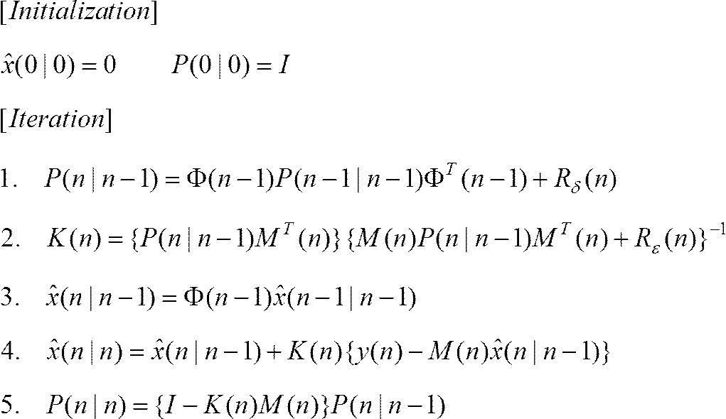
上記のアルゴリズムは、初期設定の過程[Initialization]と反復の過程[Iteration]とに大別され、反復の過程では、1~5の手順を逐次繰り返す。以下、図10を参照して、有色性駆動源付カルマンアルゴリズムの詳細について説明する。
ステップ602で、推定部64が、カルマンアルゴリズムの処理が初回か否かを判定する。初回の場合には、ステップ604へ移行し、2回目以降の場合には、ステップ606へ移行する。
ステップ604では、推定部64が、初期設定を行う。具体的には、推定部64は、所望の原画像情報を示す状態ベクトルの最適推定値(以下「最適推定値ベクトル」という)の初期値x^(0|0)、及び所望の原画像情報を示す状態ベクトルの推定誤差(以下「推定誤差ベクトル」という)の相関行列の初期値P(0|0)を、上述の初期設定の過程[Initialization]に示した初期状態に設定する。
次に、ステップ606で、推定部64が、上記ステップ400で定義した状態空間モデルにおける状態遷移行列Φ、上記ステップ604で設定した推定誤差ベクトルの相関行列の初期値P(0|0)、又は1時刻前に後述するステップ612で更新された相関行列P(n|n)、及び駆動源ベクトルの共分散行列Rδ(n)を用いて、時刻(n-1)までの情報により時刻nの状態ベクトルを推定した場合の誤差である相関行列P(n|n-1)を計算する(上述の反復の過程[Iteration]の手順1)。
次に、ステップ608で、推定部64が、上記ステップ606で計算した相関行列P(n|n-1)、上記ステップ500で定義した状態空間モデルにおける観測行列M、及び観測雑音ベクトルの共分散行列Rε(n)を用いて、カルマンゲイン行列K(n)を計算する(同手順2)。
次に、ステップ610で、推定部64が、状態遷移行列Φ、及び上記ステップ604で設定した最適推定値ベクトルの初期値x^(0|0)、又は1時刻前に本ステップで得られた最適推定値ベクトルx^(n|n)を用いて、時刻(n-1)までの情報による時刻nでの最適推定値ベクトルx^(n|n-1)を計算する(同手順3)。そして、推定部64が、計算した最適推定値ベクトルx^(n|n-1)、上記ステップ608で計算したカルマンゲイン行列K(n)、観測ベクトルy(n)、及び観測行列Mを用いて、時刻nまでの情報によるその時刻での最適推定値ベクトルx^(n|n)を計算する(同手順4)。
次に、ステップ612で、推定部64が、単位行列I、カルマンゲイン行列K(n)、観測行列M、及び上記ステップ606で計算された相関行列P(n|n-1)を用いて、時刻nまでの情報によるその時刻での相関行列P(n|n)を更新する。次に、ステップ614で、上記ステップ610で計算された最適推定値ベクトルx^(n|n)を、現在設定されている処理対象領域nの処理結果として一旦復元画像メモリ48に記憶する。
有色性駆動源付カルマンアルゴリズムが終了すると、画像復元処理ルーチン(図4)へリターンして、ステップ700へ移行し、原画像の全領域について画像復元処理が終了したか否かを判定する。全領域について処理が終了していない場合には、ステップ300へ戻って、次の処理対象領域nを設定して処理を繰り返す。全領域について処理が終了した場合には、ステップ900へ移行して、復元画像出力部65が、復元画像メモリ48に記憶された画像情報を、出力インタフェース部70を介して出力して、画像出力装置に復元画像を表示し、画像復元処理を終了する。
以上説明したように、第1の実施の形態に係る画像復元装置10によれば、観測画像の画素値のヒストグラムから算出した基準値に基づいて、観測画像の各画素が不一様なテクスチャか否か、及び各画素が地色か否かを判定する。このように、観測画像の画素値のヒストグラムから算出した基準値を用いることで、局所的に算出した基準値を用いる場合に比べ、観測画像のどの部分に生じているか不明である不一様なテクスチャについても、精度良く判定することができる。また、ヒストグラムに表れる原画像に相当する部分と不一様なテクスチャや地色に相当する部分とを精度良く分離可能な基準値を算出することができるため、画像の画素値の高低に基準値が影響され難くなる。例えば、文字部分が多い画像の場合、画像全体の画素値が低くなり、これに影響されて、基準値も低目の画素値に設定されたとする。この場合、肌色などの原画像部分が不一様なテクスチャ又は地色と判定され、除去される可能性が高まる。特に、肌色部分の劣化は人が視覚的に認識し易い要素であるため、復元画像全体の画像品質に対して大きな影響を与える。画素値のヒストグラムから基準値を算出することで、ある程度面積を有する肌色部分の画素値が基準値として設定される可能性は低くなるため、上記のような品質劣化を抑制することができる。また、ヒストグラムのピークや裾野間の中央値を基準値として算出する場合には、基準値算出の処理量を削減することができる。
そして、有色性駆動源ベクトルを含む状態方程式と、不一様なテクスチャ又は地色と判定された画素の画素値を用いて、原画像に不一様なテクスチャ及び地色が加わって観測画像となる過程を示す観測方程式とに基づいて、有色性駆動源付カルマンアルゴリズムにより、原画像の最適値を推定する。そして、この推定した最適値を、原画像を復元した復元画像とすることで、観測画像から、不一様なテクスチャ及び地色を除去して、原画像を復原することができる。
次に、第1の実施の形態に係る画像復元装置10の処理結果の一例について説明する。
図1に示すような、シワや地色を含む原稿を読み取った観測画像に対して、第1の実施の形態に係る画像復元装置10による画像復元処理を行った。なお、図1に示す文書は、実際には、一部の文字部分と、背景とが同系色(緑色)で印刷された文書である。
図11に示すように、画像復元処理後は、シワなどの不一様なテクスチャ、及び地色が除去されている。また、地色と同系色の文字部分は、除去されることなく残っており、原画像の復元性が高いことが分かる。
<第2の実施の形態>
次に、第2の実施の形態について説明する。第2の実施の形態では、両面に画像が印刷された文書をスキャンした際の裏写りを除去する画像復元装置について説明する。なお、第2の実施の形態に係る画像復元装置の構成について、第1の実施の形態に係る画像復元装置10と同一の部分については、第1の実施の形態と同一符号を付して詳細な説明を省略する。
次に、第2の実施の形態について説明する。第2の実施の形態では、両面に画像が印刷された文書をスキャンした際の裏写りを除去する画像復元装置について説明する。なお、第2の実施の形態に係る画像復元装置の構成について、第1の実施の形態に係る画像復元装置10と同一の部分については、第1の実施の形態と同一符号を付して詳細な説明を省略する。
第2の実施の形態に係る画像復元装置210は、CPU、ROM、RAM、及びHDDを含むコンピュータで構成されており、図2に示すように、入力インタフェース部20、操作部30、記憶部40、画像復元処理部260、及び出力インタフェース部70を備えている。
画像復元処理部260は、機能的には、図3に示すように、判定部261と、状態量算出部62と、観測量算出部263と、推定部264と、復元画像出力部65とを含んだ構成で表すことができる。
判定部261は、観測画像の局所領域に含まれる画素の画素値の分散値を用いた基準値と、各画素の画素値とに基づいて、各画素が、裏面の画像が表面に裏写りした画像(裏写り画像)を示す画素か否かを判定する。なお、裏写り画像も、本発明の不一様なテクスチャの一例である。
観測量算出部263は、観測画像における時刻nでの状態nに基づき、判定部261によって裏写り画像の画素と判定された画素の画素値を用いて、表面の原画像に裏写り画像が加わって観測画像となる過程を観測量として算出する。
推定部264は、観測画像における時刻nでの状態nについて、状態量算出部62により算出された状態量、及び観測量算出部263により算出された観測量から状態空間モデルに基づいた予測法を用い、状態nの最適値を推定する。
なお、画像復元処理部260の各部の処理について、第1の実施の形態と異なる点については、後述する画像復元処理ルーチンにおいて、より詳細に説明する。
次に、第2の実施の形態に係る画像復元装置210の作用について、第1の実施の形態と異なる点について説明する。
第2の実施の形態では、図4に示す画像復元処理ルーチンのステップ200において、図12に示す判定処理が実行される。
図12に示す判定処理のステップ222で、判定部61が、取込画像メモリ42から観測画像情報を取得する。
次に、ステップ224で、判定部261が、観測画像の局所領域L(例えば、3×3画素の領域)毎に、その局所領域Lに含まれる各画素のRGB成分毎の画素値に基づいて、RGB成分毎に、局所領域Lの画素値の平均値 ̄yL及び、下記(4)式に示す分散値σ2
yLを算出する。なお、Mは局所領域Lの横方向の画素数、Nは局所領域Lの縦方向の画素数である。局所領域Lのサイズは、観測画像の解像度等に応じて、任意の値を設定することができる。

次に、ステップ226で、判定部261が、上記ステップ224でRGB成分毎に算出された観測画像の局所領域L毎の画素値の平均値 ̄yL及び分散値σ2
yLから、各画素が裏写り画像を示す画素か否かを判定するための基準値ythLを下記(5)式により算出する。

次に、ステップ228で、判定部261が、取得した観測画像の局所領域Lに含まれる各画素のRGB成分毎の画素値yRm,n、yGm,n、yBm,nを用いて、下記(6)式により、観測画像をグレースケール化した場合の濃淡値ygraym,nを算出する。

次に、ステップ230で、判定部261が、観測画像の局所領域Lに含まれる各画素(m,n)のRGBのいずれかの成分の画素値ym,n及び濃淡値ygraym,nが共に基準値ythLより大きいか否かを判定する。RGBのいずれかの成分で、ym,n,ygraym,n>ythLとなる場合には、ステップ232へ移行し、判定部261が、画素(m,n)は裏写り画像を示す画素であると判定し、画像復元処理ルーチン(図4)に戻る。一方、RGBのいずれの成分についても、ym,n,ygraym,n≦ythLとなる場合には、そのまま、画像復元処理ルーチンに戻る。ステップ224~232の処理は、観測画像全体にわたって、局所領域L毎に実行する。
次に、図4のステップ300で、状態量算出部62が、原画像及び観測画像に対して、共通の処理対象領域n(例えば、3×3画素の領域)を設定する。そして、ステップ400~600において、原画像情報のみを用いて算出した状態量と、観測画像情報、原画像情報、及び裏写り画像を示す画素と判定された画素の画素値を用いて算出した観測量とで表される有色性駆動源を含む状態空間モデルを用いた有色性駆動源付カルマンアルゴリズムにより、状態量の最適値を推定する処理を実行する。
ここで、第2の実施の形態における状態空間モデルについて説明する。
両面に画像が印刷された原稿をスキャンした場合、表面の原画像に裏面の画像が裏写りする。図13に示すように、裏写りが生じている観測画像yi,jは、表面の原画像xf
i,jに、裏面の画像xb
i-p,j-qが透過し、かつぼけが生じた状態の画像が重畳された状態空間モデルによって表される。図13のsは透過率、hp,qはぼけを表す点広がり関数、l(エル)は画素値の最大値、pは画像の横方向の画素数、qは画像の縦方向の画素数である。すなわち、(l-xb
i-p,j-q)は、表面の原画像xfの画素位置(i,j)に対応する裏面の画像xbの画素位置(i-p,j-q)の画素の画素値を反転させることを表す。なお、裏面の画像が透過する透過率は、原稿の厚さ、画像の濃度、スキャン時の照明強度等に依存する。
さらに、裏写り画像が表面の原画像に与える影響は、表面の原画像の画像情報に応じて異なる。例えば、図14に示すように、表面の原画像が黒(輝度値が0)に近いほど、裏写りの影響は少なく(例えば、図14中のAで示す箇所)、表面の原画像が白(8ビットのクレースケールで輝度値が255)に近いほど、裏写りの影響を受け易い(例えば、図14中のBで示す箇所)。したがって、表面の原画像の画像情報に関係なく、一定量の裏写りが観測画像に付加されると仮定すると、原画像の復元を精度良く行うことができない。
そこで、第2の実施の形態では、図13に示す状態空間モデルに、表面の原画像の画像情報に応じて重みが変化する非線形項g(xf
i,j)を加えた状態空間モデルを用いて、原画像を推定する。したがって、第2の実施の形態における状態空間モデルは、下記(7)式で表すことができる。

非線形項g(xf
i,j)は、例えば、輝度値0~255の画素を各行に持つ表面画像xf
i,jが表面に印刷され、輝度値0~255の画素を各列に持つ裏面画像xb
i,jが裏面に印刷された原稿の表面をスキャナで読み取った観測画像yf
i,jにより、上記(7)式を変形した下記(8)式で導出することができる(参考文献「F. Merrikh-Bayat, M. Babaie-Zadeh, "A Nonlinear Blind Source Separation for Removing the Show-through Effect in the Scanned Documents", European Signal Processing Conference-EUSIPCO, Aug. 2008」)。

第2の実施の形態では、上記(8)式から算出したg(xf
i,j)を、横軸を表面画像xf
i,jの輝度値、縦軸をg(xf
i,j)としてプロットした分布結果を下記(9)式のように近似し、さらに一次のテイラー展開を行った下記(10)式を、状態空間モデルの非線形項g(xf
i,j)として用いる。なお、g(xf
i,j)は、この例に限定されず、上述のように、表面の画像情報に応じた裏写りの影響を表す重み付けを行う関数であればよい。
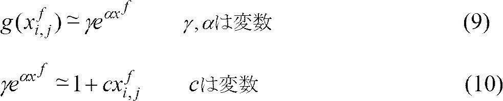
上記(10)式の非線形項、及び判定部261で裏写り画像を示す画素と判定された画素の画素値yvm,nを用いて、(7)式の状態空間モデルは、下記(11)式のように導出される。

図15に示すように、状態方程式については、第1の実施の形態と同様に構成される。なお、状態ベクトルx(n)及び駆動源ベクトルδ(n)は、表面の原画像の画素値を要素とするため、第2の実施の形態では、xf(n)及びδf(n)と表記する。
また、観測方程式については、図16に示すように、上記(11)式を適用する。図16の例では、時刻nでの観測画像における注目画素(2,2)の画素値yf
2,2(n)に着目した観測方程式である。(11)式の(1-cyvm,n)に相当する{mT-yv2,2(n)cT}が、第1の実施の形態における観測行列Mに相当する。また、第1の実施の形態における観測方程式の観測雑音ベクトルyv(n)に相当するyf
v2,2(n)には、判定部261により、注目画素(2,2)が裏写り画像を示す画素と判定されている場合には、画素値yf
2,2(n)が適用される。なお、注目画素(2,2)は、3×3画素の処理対象領域nの中心画素であるが、この例に限定されない。
図4の画像復元処理ルーチンの説明に戻って、次のステップ400で、状態量算出部62が、第1の実施の形態と同様に、時刻nにおける状態nの状態量(状態方程式)を算出する。
次に、ステップ500で、観測量算出部263が、時刻nにおける観測量(観測方程式)を算出する。
具体的には、観測量算出部263は、観測画像に設定された処理対象領域nの注目画素(2,2)の画素値yf
2,2(n)の観測方程式について、注目画素(2,2)が裏写り画像を示す画素と判定されている場合には、画素値yf
v2,2(n)をそのまま適用し、注目画素(2,2)が裏写り画像を示す画素ではない場合には、yf
v2,2(n)を0とする。さらに、観測量算出部263は、観測行列に相当する項を構成するための単位ベクトルm及び定数を示すベクトルcを用いて、画素値yf
2,2(n)の観測方程式を算出する。
次に、ステップ600で、推定部264が、上記ステップ400で算出された状態量(状態方程式)及び上記ステップ500で算出された観測量(観測方程式)により、下記に示す有色性駆動源付カルマンアルゴリズムを導出する。

第2の実施の形態における有色性駆動源付カルマンアルゴリズムにおいて、第1の実施の形態における有色性駆動源付カルマンアルゴリズムと異なる点は、観測行列Mに替えて、下記(12)式に示す行列mpを用い、観測雑音ベクトルの共分散行列Rε(n)に替えて、下記(13)式に示す行列rε(n)を用いる点、及び手順2で、カルマンゲイン行列として、行列K(n)に変えて行列k(n)を計算する点である。

以上説明したように、第2の実施の形態に係る画像復元装置210によれば、両面に画像が印刷された原稿の表面をスキャンした際に、裏面の画像が表面に裏写りしている場合に、表面の原画像情報が裏写りに与える影響を反映した非線形項を含む状態空間モデルを用いるため、原画像情報を精度良く復元することができる。
なお、第2の実施の形態においても、除去の対象を、第1の実施の形態と同様に、シワや不規則な折り目等を示す不一様なテクスチャ及び地色とすることができる。この場合、観測方程式のyn2,2に、不一様なテクスチャ又は地色と判定された画素の画素値を用いればよい。同様に、第1の実施の形態においても、除去の対象を、第2の実施の形態と同様に、裏写り画像とすることができる。この場合、観測方程式の観測雑音ベクトルyv(n)に、裏写り画像を示す画素と判定された画素の画素値を用いればよい。
<第3の実施の形態>
次に、第3の実施の形態について説明する。第3の実施の形態では、地色の除去に、第2の実施の形態と同様に非線形項を導入した画像復元装置について説明する。なお、第3の実施の形態に係る画像復元装置の構成について、第2の実施の形態に係る画像復元装置210と同一の部分については、第2の実施の形態と同一符号を付して詳細な説明を省略する。
次に、第3の実施の形態について説明する。第3の実施の形態では、地色の除去に、第2の実施の形態と同様に非線形項を導入した画像復元装置について説明する。なお、第3の実施の形態に係る画像復元装置の構成について、第2の実施の形態に係る画像復元装置210と同一の部分については、第2の実施の形態と同一符号を付して詳細な説明を省略する。
第3の実施の形態に係る画像復元装置310は、CPU、ROM、RAM、及びHDDを含むコンピュータで構成されており、図2に示すように、入力インタフェース部20、操作部30、記憶部40、画像復元処理部360、及び出力インタフェース部70を備えている。
画像復元処理部360は、機能的には、図3に示すように、判定部361と、状態量算出部62と、観測量算出部363と、推定部264と、復元画像出力部65とを含んだ構成で表すことができる。
判定部361は、第2の実施の形態における判定部261と同様の処理により、観測画像の局所領域に含まれる画素の画素値の分散値を用いた基準値と、各画素の画素値とに基づいて、各画素が地色を示す画素か否かを判定する。
観測量算出部363は、観測画像における時刻nでの状態nに基づき、判定部361によって地色を示す画素と判定された画素の画素値を用いて、原画像に地色が加わって観測画像となる過程を観測量として算出する。
ここで、第3の実施の形態における状態空間モデルについて説明する。
図17に示すように、地色を含む文書をスキャンすることにより得られる観測画像yi,jは、原画像xi,jに地色vi,jが加わった状態空間モデルによって表される。第3の実施の形態では、さらに、地色vi,jが原画像xi,jに加わる過程において、原画像の画像情報が地色に与える影響を反映した非線形項g(xi,j)を加えた状態空間モデルを用いて、原画像を推定する。したがって、第3の実施の形態における状態空間モデルは、下記(14)式で表すことができる。

非線形項g(xi,j)は、第2の実施の形態と同様に、(10)式を適用することができる。この場合、第2の実施の形態と同様に、(14)式及び(10)式から、(11)式が導出される。このため、観測量算出部363は、第2の実施の形態における観測量算出部263と同様に、時刻nにおける観測量(観測方程式)を算出することができる。この際、観測量算出部363は、注目画素(2,2)が地色示す画素と判定されている場合には、画素値yf
v2,2(n)をそのまま適用し、注目画素(2,2)が地色を示す画素ではない場合には、yf
v2,2(n)を0とする。
状態方程式及び観測方程式が第2の実施の形態と同様であるため、推定部264における有色性駆動源付カルマンアルゴリズムも、第2の実施の形態と同様に実行することができる。
以上説明したように、第3の実施の形態に係る画像復元装置310によれば、原画像情報が地色に与える影響を反映した非線形項を含む状態空間モデルを用いるため、原画像情報を精度良く復元することができる。
図18に、第3の実施の形態に係る画像復元装置310の処理結果の一例を示す。図18に示すように、画像復元処理後は、原画像に含まれる文字部分、線の間なども含め、地色が除去されていることが分かる。
また、第2及び第3実施形態に係る画像復元装置は、シワなどの不一様なテクスチャ、地色、裏写り等が複合的に生じている観測画像に対しても精度良く原画像を復元することができる。
図19に、文字及び写真が両面に印刷された原稿(実際にはカラー画像)を読み取り、裏写り及び地色が含まれている観測画像に対して本手法による復元処理を行った処理結果の一例を示す。図19に示すように、観測画像に含まれる裏写りや地色が、復元画像において除去されていることが分かる。また、人物の肌色部分なども、裏写りや地色の除去の影響による画質劣化が抑制されている。肌色部分の劣化は人が視覚的に認識し易い要素であるため、肌色部分の再現性がよいことで、復元画像全体の画像品質の向上が図れる。
また、図20に、レシートを読み取り、シワ及び地色が含まれている観測画像に対して本手法による復元処理を行った処理結果の一例を示す。図20には、非線形項を含む状態空間モデルを用いない従来手法による復元画像を比較例として示している。本手法による復元画像では、従来手法に比べ、シワ及び地色共に精度良く除去されていることが分かる。なお、図20の処理結果の本手法による復元処理には、観測方程式における観測行列にエッジ抽出フィルタを適用し、文字の鮮明化を行っている。
このように、本手法では、シワなどの不一様なテクスチャ、地色、裏写り等の除去精度が高いことから、図20に示す処理結果の一例のように、レシートなどのシワになり易い原稿の読み取りに対しても有効である。例えば、レシートをスキャンして、文字認識したレシートの内容を家計簿に記録するようなアプリケーションに本発明を適用した場合、シワの多いレシートからも精度良く原画像(レシートの内容)を復元することができるため、文字認識の誤認識を低減することができる。
<第4の実施の形態>
次に、第4の実施の形態について説明する。第4の実施の形態では、両面に画像が印刷された文書をスキャンした際の裏写りを、裏面の画像情報も用いて除去する画像復元装置について説明する。なお、第4の実施の形態に係る画像復元装置の構成について、第2の実施の形態に係る画像復元装置210と同一の部分については、第2の実施の形態と同一符号を付して詳細な説明を省略する。
次に、第4の実施の形態について説明する。第4の実施の形態では、両面に画像が印刷された文書をスキャンした際の裏写りを、裏面の画像情報も用いて除去する画像復元装置について説明する。なお、第4の実施の形態に係る画像復元装置の構成について、第2の実施の形態に係る画像復元装置210と同一の部分については、第2の実施の形態と同一符号を付して詳細な説明を省略する。
第4の実施の形態に係る画像復元装置410は、CPU、ROM、RAM、及びHDDを含むコンピュータで構成されており、図2に示すように、入力インタフェース部20、操作部30、記憶部40、画像復元処理部460、及び出力インタフェース部70を備えている。
画像復元処理部460は、機能的には、図21に示すように、位置合わせ部461と、状態量算出部62と、観測量算出部463と、推定部464と、復元画像出力部65とを含んだ構成で表すことができる。
位置合わせ部461は、表面の観測画像xf
i,jと裏面の観測画像xb
i,jとで対応する画素同士の位置合せを行う。位置合わせ部461は、例えば、ブロックマッチング等の手法により位置合せを行うことができる。また、表面と裏面とを同時にスキャンするタイプのスキャナによりスキャンされた場合など、表面の観測画像xf
i,jと裏面の観測画像xb
i,jとの位置合せに使用可能な情報を取得可能な場合には、位置合わせ部461は、その情報を取得して、位置合せを行ってもよい。
観測量算出部463は、観測画像における時刻nでの状態nに基づき、裏面の画像情報を用いて、表面の原画像に裏写り画像が加わって観測画像となる過程を観測量として算出する。
推定部464は、観測画像における時刻nでの状態nについて、状態量算出部62により算出された状態量、及び観測量算出部463により算出された観測量から状態空間モデルに基づいた予測法を用い、状態nの最適値を推定する。
なお、画像復元処理部460の各部の処理について、第2の実施の形態と異なる点については、後述する画像復元処理ルーチンにおいて、より詳細に説明する。
次に、図22を参照して、第4の実施の形態に係る画像復元装置410の作用について説明する。なお、図22に示す画像復元処理ルーチンは、記憶部40に画像復元プログラムとして格納されており、図示しないCPUによって実行される。
ステップ150で、画像入力装置であるスキャナにより、両面に文書が印刷された原稿の表面及び裏面の各々を読み取ることにより得られた表面の観測画像情報及び裏面の観測画像情報を、入力インタフェース部20を介して取り込み、主記憶部41の取込画像メモリ42に記憶する。
次に、ステップ250で、位置合わせ部461が、取込画像メモリ42から表面及び裏面の観測画像情報を取得し、表面と裏面との位置合せを行う。
ここで、第4の実施の形態における状態空間モデルについて説明する。第4の実施の形態における状態空間モデルも、第2の実施の形態における状態空間モデルと同様に、(7)式で表すことができる。そして、(7)式に(10)式に示す非線形項を適用して、(15)式に示す状態空間モデルが導出される。

上記(15)式を、時刻nでの観測画像における注目画素(2,2)の画素値yf
2,2(n)に着目した観測方程式に適用すると、下記(16)式となる。

裏面の原画像情報であるxb(n)は不明であるため、(16)式において、xb(n)を、裏面の観測画像情報で表される観測ベクトルyb(n)に置換する。これにより、(16)式は、下記(17)式のように変換される。

図22の画像復元処理ルーチンの説明に戻って、次のステップ400で、状態量算出部62が、第2の実施の形態と同様に、時刻nにおける状態nの状態量(状態方程式)を算出する。
次に、ステップ550で、観測量算出部463が、時刻nにおける観測量(観測方程式)を算出する。
具体的には、観測量算出部463は、観測画像に設定された処理対象領域nの注目画素(2,2)の画素値yf
2,2(n)の観測方程式について、観測行列に相当する項を構成するための単位ベクトルm、定数s、点広がり関数を示すベクトルh、画素値の最大値l(エル)、及び裏面の観測画像情報で表される観測ベクトルyb(n)を用いて、画素値yf
2,2(n)の観測方程式を算出する。
次に、ステップ600で、推定部264が、上記ステップ400で算出された状態量(状態方程式)及び上記ステップ550で算出された観測量(観測方程式)により、第2の実施の形態と同様に、有色性駆動源付カルマンアルゴリズムを導出する。なお、第4の実施の形態における有色性駆動源付カルマンアルゴリズムにおいては、下記(18)式に示す行列mp、及び下記(19)式に示す行列rε(n)を用いる。

以上説明したように、第4の実施の形態に係る画像復元装置410によれば、表面の原画像情報が裏写りに与える影響を反映した非線形項を含む状態空間モデルにおいて、裏面の画像情報も用いて原画像情報を復元するため、より精度良く原画像情報を復元することができる。
図23に、第4の実施の形態に係る画像復元装置410の処理結果の一例を示す。図23に示すように、画像復元処理後は、表面の画像情報と重複した裏写りも除去されていることが分かる。
なお、本発明は、上述した各実施の形態に限定されるものではなく、この発明の要旨を逸脱しない範囲内で様々な変形や応用が可能である。
例えば、上記各実施の形態では、状態(n-1)から状態nへの変化として、処理対象領域を右方向に1画素分シフトさせる場合について説明したが、これに限定されない。例えば、処理対象領域を、画像内の下方向へシフトさせてもよい。この場合、システム状態量が重なる領域を考慮した状態遷移行列Φ及び駆動源ベクトルδを構成するとよい。
また、図4のステップ200において、第1の実施の形態では図5に示す判定処理を実行し、第2及び第3の実施の形態では図12に示す判定処理を実行する場合について説明したが、これに限定されない。第1の実施の形態で図12に示す判定処理を実行してもよいし、第2及び第3の実施の形態で図5に示す判定処理を実行してもよい。また、判定処理は、図5及び図12に示す例に限定されない。例えば、観測画像の全画素の分散値から算出される基準値を用いて判定を行ってもよい。以下、図24を参照して、この場合の判定処理について説明する。
ステップ252で、判定部が、取込画像メモリ42から観測画像情報を取得する。
次に、ステップ254で、判定部が、取得した観測画像情報に含まれる各画素のRGB成分毎の画素値から、RGB成分毎に、観測画像全体の画素値の平均値 ̄yを算出する。そして、判定部、算出した平均値 ̄yを用いて、上記(4)式により、RGB成分毎に観測画像全体の画素値の分散値σ2
yを算出する。この際、(4)式の分散値σ2
yLをσ2
y、平均値 ̄yLを ̄y、Mを観測画像の横方向の画素数、Nを観測画像の縦方向の画素数と読み替える。
次に、ステップ256で、判定部が、観測画像の局所領域L(例えば、3×3画素の領域)毎に、その局所領域Lに含まれる各画素のRGB成分毎の画素値に基づいて、RGB成分毎に、局所領域Lの画素値の平均値 ̄yL及び分散値σ2
yLを算出する。分散値σ2
yLは、上記(4)式により算出する。
次に、ステップ258で、判定部が、局所領域Lの画素値の平均値 ̄yLが観測画像全体の画素値の平均値 ̄yより大きく、かつ局所領域Lの画素値の分散値σ2
yLが観測画像全体の画素値の分散値σ2
yより大きいか否かを判定する。RGBのいずれかの成分で上記判定が肯定判定となる場合には、ステップ260へ移行し、RGBのいずれの成分についても、上記判定が否定判定となる場合には、ステップ262へ移行する。
ステップ260では、判定部が、該当の局所領域Lに含まれる各画素は、不一様なテクスチャを示す画素であると判定し、ステップ262へ移行する。ステップ256~260の処理は、観測画像全体にわたって、局所領域L毎に実行する。
ステップ262では、判定部が、上記ステップ254でRGB成分毎に算出された観測画像全体の画素値の平均値 ̄y及び分散値σ2
yから、各画素が地色か否かを判定するための基準値ythを上記(5)式により算出する。この際、(5)式の分散値σ2
yLをσ2
y、平均値 ̄yLを ̄yと読み替える。
そして、判定部は、観測画像に含まれる各画素(m,n)の画素値ym,nが基準値ythより大きいか否かを判定する。RGBのいずれかの成分で、ym,n>ythとなる場合には、ステップ266へ移行し、判定部が、画素(m,n)は地色を示す画素であると判定し、画像復元処理ルーチン(図4)に戻る。一方、RGBのいずれの成分についても、ym,n≦ythとなる場合には、そのまま、画像復元処理ルーチンに戻る。ステップ264及び266の処理は、観測画像に含まれる全画素について、画素毎に実行する。
また、上記各実施の形態では、文書をスキャナで読み取ることにより観測画像情報を取得する場合について説明したが、これに限定されず、様々な分野で撮影された画像を観測画像として用いてもよい。例えば、医療用画像や、建築・土木の現場などで、点検や検査のために撮影された画像などを、観測画像として用いてもよい。これにより、医療分野、建築・土木分野等、様々な分野において、リアルタイムな画像分析などに本発明を応用することができる。
また、上記各実施の形態では、CPUによりプログラムを実行することで各部の処理を実行する場合について説明したが、各部をハードウエアにより構成するようにしてもよい。
10、210、310、410 画像復元装置
20 入力インタフェース部
30 操作部
40 記憶部
60、260、360、460 画像復元処理部
61、261、361、461 判定部
62 状態量算出部
63、263、363、463 観測量算出部
64、264、464 推定部
65 復元画像出力部
70 出力インタフェース部
20 入力インタフェース部
30 操作部
40 記憶部
60、260、360、460 画像復元処理部
61、261、361、461 判定部
62 状態量算出部
63、263、363、463 観測量算出部
64、264、464 推定部
65 復元画像出力部
70 出力インタフェース部
Claims (10)
- 原画像情報に不一様なテクスチャ及び地色の少なくとも一方が混在した観測画像情報に対し、前記原画像情報を駆動源として含む状態空間モデルに基づく予測法を用い、前記観測画像情報から前記原画像情報を推定する画像復元装置であって、
前記観測画像情報に含まれる画素の画素値の分布から算出される基準値と、前記観測画像情報に含まれる各画素の画素値とに基づいて、前記観測画像情報の各画素が前記不一様なテクスチャ及び前記地色の少なくとも一方か否かを判定する判定手段と、
前記原画像情報の時刻nでの状態nにおける状態量を、時刻(n-1)での状態(n-1)の状態量、前記状態(n-1)から前記状態nへの状態遷移、及び前記状態(n-1)の状態量に含まれない前記状態nの状態量の要素を含む前記駆動源を用いて算出する状態量算出手段と、
前記原画像情報に前記不一様なテクスチャ及び前記地色の少なくとも一方が加わって観測画像情報となる過程を表す観測量を、前記状態nの状態量、及び前記判定手段により前記不一様なテクスチャ及び前記地色の少なくとも一方と判定された画素の画素値を用いて算出する観測量算出手段と、
前記状態量算出手段により算出された状態量、及び前記観測量算出手段により算出された観測量に基づいて、前記状態空間モデルに基づく予測法により、前記状態nの状態量の最適値を原画像情報として推定する推定手段と、
を含む画像復元装置。 - 原画像情報に不一様なテクスチャ及び地色の少なくとも一方が混在した観測画像情報に対し、前記原画像情報を駆動源として含む状態空間モデルに基づく予測法を用い、前記観測画像情報から前記原画像情報を推定する画像復元装置であって、
前記観測画像情報に含まれる画素の画素値に基づく基準値と、前記観測画像情報に含まれる各画素の画素値とに基づいて、前記観測画像情報の各画素が前記不一様なテクスチャ及び前記地色の少なくとも一方か否かを判定する判定手段と、
前記原画像情報の時刻nでの状態nにおける状態量を、時刻(n-1)での状態(n-1)の状態量、前記状態(n-1)から前記状態nへの状態遷移、及び前記状態(n-1)の状態量に含まれない前記状態nの状態量の要素を含む前記駆動源を用いて算出する状態量算出手段と、
前記原画像情報に前記不一様なテクスチャ及び前記地色の少なくとも一方が加わって観測画像情報となる過程を表す観測量を、前記状態nの状態量、前記判定手段により前記不一様なテクスチャ及び前記地色の少なくとも一方と判定された画素の画素値、及び前記原画像情報に応じて前記過程に与える影響を表した非線形項を用いて算出する観測量算出手段と、
前記状態量算出手段により算出された状態量、及び前記観測量算出手段により算出された観測量に基づいて、前記状態空間モデルに基づく予測法により、前記状態nの状態量の最適値を原画像情報として推定する推定手段と、
を含む画像復元装置。 - 前記観測画像情報は、両面に画像を有する文書を読み取ることにより得られ、
前記不一様なテクスチャは、前記文書の原画像情報を有する面に、他方の面の画像が裏写りした裏写り画像情報であり、
前記観測量算出手段は、前記裏写り画像情報に前記非線形項を乗算して、前記原画像情報に加えることにより、前記観測量を算出する
請求項2に記載の画像復元装置。 - 前記観測量算出手段は、前記判定手段により前記不一様なテクスチャと判定された画素の画素値を、前記裏写り画像情報として用いる請求項3に記載の画像復元装置。
- 前記観測量算出手段は、前記文書の裏面を読み取ることにより得られた裏面観測情報を、前記裏写り画像情報として用いる請求項3に記載の画像復元装置。
- 前記不一様なテクスチャは、前記観測画像情報が示す画像に含まれるシワ及び折り目、並びに前記観測画像情報が示す画像の背景に施されたグラデーションの少なくとも一つであり、
前記観測量算出手段は、前記不一様なテクスチャを示すテクスチャ画像情報に前記非線形項を乗算して、前記原画像情報に加算することにより、前記観測量を算出する
請求項2に記載の画像復元装置。 - 前記基準値は、前記観測画像情報に含まれる画素の画素値の分布から算出される値である請求項2~請求項6のいずれか1項に記載の画像復元装置。
- 原画像情報に不一様なテクスチャ及び地色の少なくとも一方が混在した観測画像情報に対し、前記原画像情報を駆動源として含む状態空間モデルに基づく予測法を用い、前記観測画像情報から前記原画像情報を推定する画像復元方法であって、
判定手段が、前記観測画像情報に含まれる画素の画素値の分布から算出される基準値と、前記観測画像情報に含まれる各画素の画素値とに基づいて、前記観測画像情報の各画素が前記不一様なテクスチャ及び前記地色の少なくとも一方か否かを判定し、
状態量算出手段が、前記原画像情報の時刻nでの状態nにおける状態量を、時刻(n-1)での状態(n-1)の状態量、前記状態(n-1)から前記状態nへの状態遷移、及び前記状態(n-1)の状態量に含まれない前記状態nの状態量の要素を含む前記駆動源を用いて算出し、
観測量算出手段が、前記原画像情報に前記不一様なテクスチャ及び前記地色の少なくとも一方が加わって観測画像情報となる過程を表す観測量を、前記状態nの状態量、及び前記判定手段により前記不一様なテクスチャ及び前記地色の少なくとも一方と判定された画素の画素値を用いて算出し、
推定手段が、前記状態量算出手段により算出された状態量、及び前記観測量算出手段により算出された観測量に基づいて、前記状態空間モデルに基づく予測法により、前記状態nの状態量の最適値を原画像情報として推定する
画像復元方法。 - 原画像情報に不一様なテクスチャ及び地色の少なくとも一方が混在した観測画像情報に対し、前記原画像情報を駆動源として含む状態空間モデルに基づく予測法を用い、前記観測画像情報から前記原画像情報を推定する画像復元方法であって、
判定手段が、前記観測画像情報に含まれる画素の画素値に基づく基準値と、前記観測画像情報に含まれる各画素の画素値とに基づいて、前記観測画像情報の各画素が前記不一様なテクスチャ及び前記地色の少なくとも一方か否かを判定し、
状態量算出手段が、前記原画像情報の時刻nでの状態nにおける状態量を、時刻(n-1)での状態(n-1)の状態量、前記状態(n-1)から前記状態nへの状態遷移、及び前記状態(n-1)の状態量に含まれない前記状態nの状態量の要素を含む前記駆動源を用いて算出し、
観測量算出手段が、前記原画像情報に前記不一様なテクスチャ及び前記地色の少なくとも一方が加わって観測画像情報となる過程を表す観測量を、前記状態nの状態量、前記判定手段により前記不一様なテクスチャ及び前記地色の少なくとも一方と判定された画素の画素値、及び前記原画像情報に応じて前記過程に与える影響を表した非線形項を用いて算出し、
推定手段が、前記状態量算出手段により算出された状態量、及び前記観測量算出手段により算出された観測量に基づいて、前記状態空間モデルに基づく予測法により、前記状態nの状態量の最適値を原画像情報として推定する
画像復元方法。 - コンピュータを、請求項1~請求項7のいずれか1項に記載の画像復元装置を構成する各手段として機能させるための画像復元プログラム。
Priority Applications (1)
| Application Number | Priority Date | Filing Date | Title |
|---|---|---|---|
| JP2018552951A JP7029140B2 (ja) | 2016-11-28 | 2017-11-22 | 画像復元装置、方法、及びプログラム |
Applications Claiming Priority (2)
| Application Number | Priority Date | Filing Date | Title |
|---|---|---|---|
| JP2016-229777 | 2016-11-28 | ||
| JP2016229777 | 2016-11-28 |
Publications (1)
| Publication Number | Publication Date |
|---|---|
| WO2018097211A1 true WO2018097211A1 (ja) | 2018-05-31 |
Family
ID=62195076
Family Applications (1)
| Application Number | Title | Priority Date | Filing Date |
|---|---|---|---|
| PCT/JP2017/042106 Ceased WO2018097211A1 (ja) | 2016-11-28 | 2017-11-22 | 画像復元装置、方法、及びプログラム |
Country Status (2)
| Country | Link |
|---|---|
| JP (1) | JP7029140B2 (ja) |
| WO (1) | WO2018097211A1 (ja) |
Citations (3)
| Publication number | Priority date | Publication date | Assignee | Title |
|---|---|---|---|---|
| JP2011165013A (ja) * | 2010-02-10 | 2011-08-25 | Tokyo Univ Of Science | 画像復元装置および画像復元方法 |
| JP2014038366A (ja) * | 2012-08-10 | 2014-02-27 | Tokyo Univ Of Science | 画像復元装置、方法、及びプログラム |
| JP2015156539A (ja) * | 2014-02-19 | 2015-08-27 | 学校法人東京理科大学 | 画像復元装置、方法、及びプログラム |
Family Cites Families (2)
| Publication number | Priority date | Publication date | Assignee | Title |
|---|---|---|---|---|
| JP3917341B2 (ja) | 2000-01-05 | 2007-05-23 | 株式会社東芝 | 画像処理装置 |
| JP2011055304A (ja) | 2009-09-02 | 2011-03-17 | Murata Machinery Ltd | 画像処理装置 |
-
2017
- 2017-11-22 WO PCT/JP2017/042106 patent/WO2018097211A1/ja not_active Ceased
- 2017-11-22 JP JP2018552951A patent/JP7029140B2/ja active Active
Patent Citations (3)
| Publication number | Priority date | Publication date | Assignee | Title |
|---|---|---|---|---|
| JP2011165013A (ja) * | 2010-02-10 | 2011-08-25 | Tokyo Univ Of Science | 画像復元装置および画像復元方法 |
| JP2014038366A (ja) * | 2012-08-10 | 2014-02-27 | Tokyo Univ Of Science | 画像復元装置、方法、及びプログラム |
| JP2015156539A (ja) * | 2014-02-19 | 2015-08-27 | 学校法人東京理科大学 | 画像復元装置、方法、及びプログラム |
Also Published As
| Publication number | Publication date |
|---|---|
| JP7029140B2 (ja) | 2022-03-04 |
| JPWO2018097211A1 (ja) | 2019-11-07 |
Similar Documents
| Publication | Publication Date | Title |
|---|---|---|
| Du et al. | UIEDP: Boosting underwater image enhancement with diffusion prior | |
| CN108257095B (zh) | 用于处理图像的系统 | |
| JP5566811B2 (ja) | プリントアンドスキャン文書の画像評価のためのボケ除去および監視適応的スレッショルディング | |
| JP5754065B2 (ja) | 光学文字認識されるテキスト画像のテキスト解像度の改善方法及びシステム | |
| Mahmoudi et al. | Fast image and video denoising via nonlocal means of similar neighborhoods | |
| JP4118749B2 (ja) | 画像処理装置、画像処理プログラムおよび記憶媒体 | |
| JP4792109B2 (ja) | 画像特徴を意識した画像欠陥除去 | |
| Purkait et al. | Super resolution image reconstruction through Bregman iteration using morphologic regularization | |
| CN102737240B (zh) | 分析数字文档图像的方法 | |
| US20230343119A1 (en) | Captured document image enhancement | |
| JP2010154319A (ja) | 画像処理装置、画像処理方法、及びプログラム | |
| JP7160211B2 (ja) | 機械学習モデル、生成装置、コンピュータプログラム | |
| JP4804382B2 (ja) | 画像処理方法、画像処理プログラムおよび画像処理装置 | |
| Ko et al. | Low cost blur image detection and estimation for mobile devices | |
| JP7029140B2 (ja) | 画像復元装置、方法、及びプログラム | |
| KR20080034757A (ko) | 화상형성장치 및 화상형성방법 | |
| Nishida et al. | A multiscale approach to restoring scanned color document images with show-through effects | |
| Ji et al. | An efficient method for scanned images by using color-correction and L0 gradient minimization | |
| JP2000115526A (ja) | 画像処理装置およびエッジ処理方法 | |
| JP5963166B2 (ja) | 画像復元装置、方法、及びプログラム | |
| Nguyen et al. | A variational method for dejittering large fluorescence line scanner images | |
| JP7377661B2 (ja) | 画像の意味的領域分割装置、領域検知感度向上方法、及びプログラム | |
| JP6308496B2 (ja) | 画像復元装置、方法、及びプログラム | |
| Nawreen et al. | Stabilization of turbulence-degraded video using patch-based reference frame | |
| CN119323792B (zh) | 一种票据文字识别方法 |
Legal Events
| Date | Code | Title | Description |
|---|---|---|---|
| 121 | Ep: the epo has been informed by wipo that ep was designated in this application |
Ref document number: 17873347 Country of ref document: EP Kind code of ref document: A1 |
|
| ENP | Entry into the national phase |
Ref document number: 2018552951 Country of ref document: JP Kind code of ref document: A |
|
| NENP | Non-entry into the national phase |
Ref country code: DE |
|
| 122 | Ep: pct application non-entry in european phase |
Ref document number: 17873347 Country of ref document: EP Kind code of ref document: A1 |