WO2018097030A1 - 情報処理装置、情報処理方法、情報処理システム及びプログラム - Google Patents
情報処理装置、情報処理方法、情報処理システム及びプログラム Download PDFInfo
- Publication number
- WO2018097030A1 WO2018097030A1 PCT/JP2017/041317 JP2017041317W WO2018097030A1 WO 2018097030 A1 WO2018097030 A1 WO 2018097030A1 JP 2017041317 W JP2017041317 W JP 2017041317W WO 2018097030 A1 WO2018097030 A1 WO 2018097030A1
- Authority
- WO
- WIPO (PCT)
- Prior art keywords
- image
- photoacoustic
- time point
- ultrasonic
- information
- Prior art date
- Legal status (The legal status is an assumption and is not a legal conclusion. Google has not performed a legal analysis and makes no representation as to the accuracy of the status listed.)
- Ceased
Links
Images







Classifications
-
- A—HUMAN NECESSITIES
- A61—MEDICAL OR VETERINARY SCIENCE; HYGIENE
- A61B—DIAGNOSIS; SURGERY; IDENTIFICATION
- A61B8/00—Diagnosis using ultrasonic, sonic or infrasonic waves
- A61B8/52—Devices using data or image processing specially adapted for diagnosis using ultrasonic, sonic or infrasonic waves
- A61B8/5207—Devices using data or image processing specially adapted for diagnosis using ultrasonic, sonic or infrasonic waves involving processing of raw data to produce diagnostic data, e.g. for generating an image
-
- A—HUMAN NECESSITIES
- A61—MEDICAL OR VETERINARY SCIENCE; HYGIENE
- A61B—DIAGNOSIS; SURGERY; IDENTIFICATION
- A61B5/00—Measuring for diagnostic purposes; Identification of persons
- A61B5/0033—Features or image-related aspects of imaging apparatus, e.g. for MRI, optical tomography or impedance tomography apparatus; Arrangements of imaging apparatus in a room
- A61B5/0035—Features or image-related aspects of imaging apparatus, e.g. for MRI, optical tomography or impedance tomography apparatus; Arrangements of imaging apparatus in a room adapted for acquisition of images from more than one imaging mode, e.g. combining MRI and optical tomography
-
- A—HUMAN NECESSITIES
- A61—MEDICAL OR VETERINARY SCIENCE; HYGIENE
- A61B—DIAGNOSIS; SURGERY; IDENTIFICATION
- A61B5/00—Measuring for diagnostic purposes; Identification of persons
- A61B5/0059—Measuring for diagnostic purposes; Identification of persons using light, e.g. diagnosis by transillumination, diascopy, fluorescence
-
- A—HUMAN NECESSITIES
- A61—MEDICAL OR VETERINARY SCIENCE; HYGIENE
- A61B—DIAGNOSIS; SURGERY; IDENTIFICATION
- A61B5/00—Measuring for diagnostic purposes; Identification of persons
- A61B5/0093—Detecting, measuring or recording by applying one single type of energy and measuring its conversion into another type of energy
- A61B5/0095—Detecting, measuring or recording by applying one single type of energy and measuring its conversion into another type of energy by applying light and detecting acoustic waves, i.e. photoacoustic measurements
-
- A—HUMAN NECESSITIES
- A61—MEDICAL OR VETERINARY SCIENCE; HYGIENE
- A61B—DIAGNOSIS; SURGERY; IDENTIFICATION
- A61B8/00—Diagnosis using ultrasonic, sonic or infrasonic waves
- A61B8/13—Tomography
-
- A—HUMAN NECESSITIES
- A61—MEDICAL OR VETERINARY SCIENCE; HYGIENE
- A61B—DIAGNOSIS; SURGERY; IDENTIFICATION
- A61B8/00—Diagnosis using ultrasonic, sonic or infrasonic waves
- A61B8/13—Tomography
- A61B8/14—Echo-tomography
-
- A—HUMAN NECESSITIES
- A61—MEDICAL OR VETERINARY SCIENCE; HYGIENE
- A61B—DIAGNOSIS; SURGERY; IDENTIFICATION
- A61B8/00—Diagnosis using ultrasonic, sonic or infrasonic waves
- A61B8/52—Devices using data or image processing specially adapted for diagnosis using ultrasonic, sonic or infrasonic waves
- A61B8/5215—Devices using data or image processing specially adapted for diagnosis using ultrasonic, sonic or infrasonic waves involving processing of medical diagnostic data
- A61B8/5238—Devices using data or image processing specially adapted for diagnosis using ultrasonic, sonic or infrasonic waves involving processing of medical diagnostic data for combining image data of patient, e.g. merging several images from different acquisition modes into one image
- A61B8/5261—Devices using data or image processing specially adapted for diagnosis using ultrasonic, sonic or infrasonic waves involving processing of medical diagnostic data for combining image data of patient, e.g. merging several images from different acquisition modes into one image combining images from different diagnostic modalities, e.g. ultrasound and X-ray
-
- A—HUMAN NECESSITIES
- A61—MEDICAL OR VETERINARY SCIENCE; HYGIENE
- A61B—DIAGNOSIS; SURGERY; IDENTIFICATION
- A61B8/00—Diagnosis using ultrasonic, sonic or infrasonic waves
- A61B8/48—Diagnostic techniques
- A61B8/483—Diagnostic techniques involving the acquisition of a 3D volume of data
Definitions
- the present disclosure relates to an information processing apparatus, an information processing method, an information processing system, and a program.
- An ultrasonic imaging device or a photoacoustic imaging device is used as an imaging device that images a state inside a subject in a minimally invasive manner.
- Patent Document 1 in an apparatus that can acquire an ultrasonic image at a frame rate higher than that of a photoacoustic image, information on the frame of the photoacoustic image corresponding to the frame of the ultrasonic image and light corresponding to the frame of the ultrasonic image are disclosed. It is disclosed that incidental information including information indicating that there is no frame of an acoustic image is generated.
- An ultrasonic image and a photoacoustic image are obtained based on incidental information in which information on the frame of the photoacoustic image corresponding to the frame of the ultrasonic image and information indicating that there is no frame of the corresponding photoacoustic image are described.
- incidental information in which information on the frame of the photoacoustic image corresponding to the frame of the ultrasonic image and information indicating that there is no frame of the corresponding photoacoustic image are described.
- An information processing apparatus is a photoacoustic signal that is a photoacoustic signal generated by light irradiation on a subject, the first photoacoustic signal at a first time point, and the first A second photoacoustic signal at a second time point after the first time point, and an ultrasonic signal that is a signal related to a reflected wave of the ultrasonic wave irradiated to the subject, the first time point and Signal acquisition means for acquiring an ultrasonic signal at a third time point between the second time point and an ultrasonic image based on the ultrasonic signal, and a photoacoustic image based on the photoacoustic signal Based on the first photoacoustic signal and the second photoacoustic signal with respect to an ultrasonic image generated based on the image acquisition means to acquire and the ultrasonic signal acquired at the third time point And processing means for associating any of the generated photoacoustic images. Characterized in that it.
- an acoustic wave generated by irradiating a subject with light and expanding inside the subject is referred to as a photoacoustic wave.
- an acoustic wave transmitted from the transducer or a reflected wave (echo) in which the transmitted acoustic wave is reflected inside the subject is referred to as an ultrasonic wave.
- an imaging method using ultrasonic waves and an imaging method using photoacoustics are used.
- the method of imaging using ultrasonic waves is, for example, that the ultrasonic waves oscillated from the transducer are reflected by the tissue inside the subject according to the difference in acoustic impedance, and the time until the reflected wave reaches the transducer and the reflected wave.
- An image imaged using ultrasound is hereinafter referred to as an ultrasound image.
- the user can operate while changing the angle of the probe and observe ultrasonic images of various cross sections in real time. Ultrasound images depict the shapes of organs and tissues and are used to find tumors.
- the imaging method using photoacoustics is a method of generating an image based on, for example, an ultrasonic wave (photoacoustic wave) generated by adiabatic expansion of a tissue inside a subject irradiated with light.
- An image imaged using the photoacoustic wave is hereinafter referred to as a photoacoustic image.
- the photoacoustic image information related to optical characteristics such as the degree of light absorption of each tissue is depicted.
- photoacoustic images for example, it is known that blood vessels can be drawn by the optical characteristics of hemoglobin, and its use for evaluating the malignancy of tumors is being studied.
- an imaging device for obtaining an image obtained by combining the characteristics of an ultrasonic image and a photoacoustic image has been studied.
- both an ultrasonic image and a photoacoustic image are imaged using ultrasonic waves from a subject, it is also possible to perform imaging of an ultrasonic image and photoacoustic image with the same imaging device.
- a configuration can be adopted in which the reflected wave and the photoacoustic applied to the subject are received by the same transducer.
- the user may observe the image while comparing the ultrasonic image and the photoacoustic image. . Therefore, it is preferable from the viewpoint of the workflow when the user observes these images to associate the ultrasonic image to be compared with the photoacoustic image in advance.
- the process of acquiring a photoacoustic signal and generating a photoacoustic image may take longer than the process of acquiring an ultrasonic signal and generating an ultrasonic image.
- the frame rate of the photoacoustic image may be lower than that of the ultrasonic image. Then, only by associating the ultrasonic image and the photoacoustic image based on the ultrasonic signal and the photoacoustic signal acquired substantially simultaneously, a part of the ultrasonic image having a high frame rate does not correspond to the photoacoustic image.
- the photoacoustic image is intermittently displayed with respect to the moving image of the ultrasonic image, and the visibility of the photoacoustic image may be reduced.
- An object of the first embodiment is to output data that allows both an ultrasonic image and a photoacoustic image to be smoothly reproduced when a moving image is reproduced by a viewer.
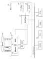
- FIG. 1 is a diagram illustrating an example of a configuration of an inspection system 102 including an information processing apparatus 107 according to the first embodiment.
- An inspection system 102 capable of generating an ultrasonic image and a photoacoustic image is connected to various external devices via a network 110.
- Each configuration and various external devices included in the inspection system 102 do not need to be installed in the same facility, and may be connected to be communicable.
- the inspection system 102 includes an information processing device 107, a probe 103, a signal collection unit 104, a display unit 109, and an operation unit 108.
- the information processing apparatus 107 acquires information related to an examination including imaging of an ultrasonic image and a photoacoustic image from the HIS / RIS 111, and controls the probe 103 and the display unit 109 when the examination is performed.
- the information processing apparatus 107 acquires an ultrasonic signal and a photoacoustic signal from the probe 103 and the signal collection unit 104.
- the information processing apparatus 107 acquires an ultrasonic image based on the ultrasonic signal, and acquires a photoacoustic image based on the photoacoustic signal.
- the information processing apparatus 107 may acquire a superimposed image obtained by further superimposing a photoacoustic image on an ultrasonic image.
- the information processing device 107 transmits and receives information to and from external devices such as the HIS / RIS 111 and the PACS 112 in accordance with standards such as HL7 (Health level 7) and DICOM (Digital Imaging and Communications in Medicine).
- the region in the subject 101 where the ultrasound image is picked up by the inspection system 102 is, for example, a circulatory region, a breast, a liver, a pancreas, and an abdomen. Further, in the inspection system 102, for example, an ultrasonic image of a subject to which an ultrasonic contrast agent using microbubbles is administered may be captured.
- the region in the subject from which the photoacoustic image is picked up by the inspection system 102 is, for example, a circulatory region, a breast, a diameter portion, an abdomen, a limb including fingers and toes.
- a blood vessel region including a new blood vessel and a plaque on a blood vessel wall may be set as a target for imaging a photoacoustic image in accordance with the characteristics relating to light absorption in the subject.
- a photoacoustic image of a subject 101 to which a dye such as methylene blue or indocyanine green, gold fine particles, or a substance obtained by integrating or chemically modifying them is administered as a contrast agent is captured. May be.
- the probe 103 is operated by a user and transmits an ultrasonic signal and a photoacoustic signal to the signal collecting unit 104 and the information processing device 107.
- the probe 103 includes a transmission / reception unit 105 and an irradiation unit 106.
- the probe 103 transmits ultrasonic waves from the transmission / reception unit 105, and receives reflected waves at the transmission / reception unit 105. Further, the probe 103 irradiates the subject with light from the irradiation unit 106, and the photoacoustic is received by the transmission / reception unit 105.
- the probe 103 is controlled so as to execute transmission of ultrasonic waves for acquiring an ultrasonic signal and light irradiation for acquiring a photoacoustic signal when information indicating contact with the subject is received. It is preferable.
- the transmission / reception unit 105 includes at least one transducer (not shown), a matching layer (not shown), a damper (not shown), and an acoustic lens (not shown).
- the transducer (not shown) is made of a material exhibiting a piezoelectric effect, such as PZT (lead zirconate titanate) or PVDF (polyvinylidene difluoride).
- the transducer (not shown) may be other than a piezoelectric element, for example, a transducer using a capacitive transducer (CMUT: capacitive ultrasonic transducer) or a Fabry-Perot interferometer.
- CMUT capacitive ultrasonic transducer
- the ultrasonic signal has frequency components of 2 to 20 MHz and the photoacoustic signal has a frequency component of 0.1 to 100 MHz, and a transducer (not shown) that can detect these frequencies is used, for example.
- the signal obtained by the transducer (not shown) is a time-resolved signal.
- the amplitude of the received signal represents a value based on the sound pressure received by the transducer at each time.
- the transmission / reception unit 105 includes a circuit (not shown) for electronic focusing or a control unit.
- the array form of transducers (not shown) is, for example, a sector, a linear array, a convex, an annular array, or a matrix array.
- the probe 103 acquires an ultrasonic signal and a photoacoustic signal.
- the probe 103 may alternately acquire an ultrasonic signal and a photoacoustic signal, may acquire them simultaneously, or may acquire them in a predetermined manner.
- the transmission / reception unit 105 may include an amplifier (not shown) that amplifies a time-series analog signal received by a transducer (not shown).
- the transducer (not shown) may be divided into a transmitter and a receiver depending on the purpose of imaging an ultrasonic image. Further, the transducer (not shown) may be divided into an ultrasonic image capturing unit and a photoacoustic image capturing unit.
- the irradiation unit 106 includes a light source (not shown) for acquiring a photoacoustic signal and an optical system (not shown) that guides pulsed light emitted from the light source (not shown) to the subject.
- the pulse width of light emitted from a light source (not shown) is, for example, 1 ns or more and 100 ns or less.
- the wavelength of the light which a light source (not shown) injects is a wavelength of 400 nm or more and 1600 nm or less, for example.
- a wavelength of 400 nm or more and 700 nm or less and a large absorption in the blood vessel is preferable.
- the wavelength of 700 nm or more and 1100 nm or less which is hard to be absorbed by tissues such as water and fat is preferable.
- the light source (not shown) is, for example, a laser or a light emitting diode.
- the irradiation unit 106 may use a light source that can convert wavelengths in order to acquire a photoacoustic signal using light of a plurality of wavelengths.
- the irradiation unit 106 may include a plurality of light sources that generate light of different wavelengths, and may be configured to irradiate light of different wavelengths from each light source.
- the laser is, for example, a solid laser, a gas laser, a dye laser, or a semiconductor laser.
- a pulsed laser such as an Nd: YAG laser or an alexandrite laser may be used.
- a Ti: sa laser or an OPO (optical parametric oscillators) laser that uses Nd: YAG laser light as excitation light may be used as a light source (not shown).
- a microwave source may be used as a light source (not shown).
- optical elements such as lenses, mirrors, and optical fibers are used.
- the optical system may include a diffusion plate that diffuses the emitted light.
- the optical system may include a lens or the like so that the beam can be focused.
- the signal collecting unit 104 converts the analog signal related to the reflected wave and the photoacoustic wave received by the probe 103 into a digital signal.
- the signal collection unit 104 transmits the ultrasonic signal and the photoacoustic signal converted into a digital signal to the information processing apparatus 107.
- the display unit 109 displays an image captured by the inspection system 102 and information related to the inspection based on the control from the information processing apparatus 107.
- the display unit 109 provides an interface for receiving a user instruction based on control from the information processing apparatus 107.
- the display unit 109 is, for example, a liquid crystal display.
- the operation unit 108 transmits information related to user operation input to the information processing apparatus 107.
- the operation unit 108 is, for example, a keyboard, a trackball, and various buttons for performing operation inputs related to inspection.
- the display unit 109 and the operation unit 108 may be integrated as a touch panel display. Further, the information processing device 107, the display unit 109, and the operation unit 108 do not need to be separate devices, and may be realized as an operation console in which these configurations are integrated.
- the information processing apparatus 107 may have a plurality of probes.
- the HIS / RIS 111 is a system for managing patient information and examination information.
- the HIS Hospital Information System
- the HIS includes an electronic medical record system, an ordering system, and a medical accounting system.
- the RIS Radiology Information System
- the inspection information includes an inspection ID for uniquely identifying and information regarding the imaging technique included in the inspection.
- An ordering system constructed for each department may be connected to the inspection system 102 instead of the RIS or in addition to the RIS. From the HIS / RIS 111, inspection order issuance to accounting are managed in a coordinated manner.
- the HIS / RIS 111 transmits information on inspection performed by the inspection system 102 to the information processing apparatus 107.
- the HIS / RIS 111 receives information regarding the progress of the inspection from the information processing apparatus 107.
- the HIS / RIS 111 performs processing for accounting.
- a PACS (Picture Archiving and Communication System) 112 is a database system that holds images obtained by various imaging devices inside and outside the facility.
- the PACS 112 manages a storage unit (not shown) that stores supplementary information such as medical images, imaging conditions of such medical images, image processing parameters including reconstruction, and patient information, and information stored in the storage unit.
- a controller (not shown).
- the PACS 112 stores an ultrasonic image, a photoacoustic image, and a superimposed image that are objects output from the information processing apparatus 107. It is preferable that communication between the PACS 112 and the information processing apparatus 107 and various images stored in the PACS 112 comply with standards such as HL7 and DICOM. Various images output from the information processing apparatus 107 are stored with associated information associated with various tags in accordance with the DICOM standard.
- Viewer 113 is a terminal for image diagnosis, and reads an image stored in PACS 112 and displays it for diagnosis.
- the doctor displays an image on the Viewer 113 for observation, and records information obtained as a result of the observation as an image diagnosis report.
- the diagnostic imaging report created using the Viewer 113 may be stored in the Viewer 113, or may be output and stored in the PACS 112 or a report server (not shown).
- the printer 114 prints an image stored in the PACS 112 or the like.
- the Printer 114 is, for example, a film printer, and outputs an image stored in the PACS 112 or the like by printing it on a film.
- FIG. 2 is a diagram illustrating an example of a hardware configuration of the information processing apparatus 107.
- the information processing apparatus 107 is a computer, for example.
- the information processing apparatus 107 includes a CPU 201, ROM 202, RAM 203, storage device 204, USB 205, communication circuit 206, probe connector port 207, and graphics board 208. These are communicably connected by BUS.
- the BUS is used to transmit and receive data between connected hardware and to transmit commands from the CPU 201 to other hardware.
- a CPU (Central Processing Unit) 201 is a control circuit that integrally controls the information processing apparatus 107 and each unit connected thereto.
- the CPU 201 performs control by executing a program stored in the ROM 202.
- the CPU 201 executes a display driver that is software for controlling the display unit 109 and performs display control on the display unit 109.
- the CPU 201 performs input / output control for the operation unit 108.
- a ROM (Read Only Memory) 202 stores a program and data in which a control procedure by the CPU 201 is stored.
- the ROM 202 stores a boot program for the information processing apparatus 107 and various initial data.
- various programs for realizing the processing of the information processing apparatus 107 are stored.
- a RAM (Random Access Memory) 203 provides a working storage area when the CPU 201 performs control by an instruction program.
- the RAM 203 has a stack and a work area.
- the RAM 203 stores a program for executing processing in the information processing apparatus 107 and each unit connected thereto, and various parameters used in image processing.
- the RAM 203 stores a control program executed by the CPU 201, and temporarily stores various data when the CPU 201 executes various controls.
- the storage device 204 is an auxiliary storage device that stores various data such as ultrasonic images and photoacoustic images.
- the storage device 204 is, for example, an HDD (Hard Disk Drive) or an SSD (Solid State Drive).
- a USB (Universal Serial Bus) 205 is a connection unit connected to the operation unit 108.
- the communication circuit 206 is a circuit for communicating with each part constituting the inspection system 102 and various external devices connected to the network 110.
- the communication circuit 206 stores output information in a transfer packet, for example, and outputs the information to an external device via the network 110 by a communication technique such as TCP / IP.
- the information processing apparatus 107 may have a plurality of communication circuits in accordance with a desired communication form.
- the probe connector port 207 is a connection port for connecting the probe 103 to the information processing apparatus 107.
- the graphics board 208 includes a GPU (Graphics Processing Unit) and a video memory.
- the GPU performs an operation related to reconstruction processing for generating a photoacoustic image from a photoacoustic signal.
- HDMI registered trademark
- High Definition Multimedia Interface 209 is a connection unit connected to the display unit 109.
- the CPU 201 and the GPU are examples of processors.
- the ROM 202, RAM 203, and storage device 204 are examples of memories.
- the information processing apparatus 107 may have a plurality of processors. In the first embodiment, the function of each unit of the information processing apparatus 107 is realized by the processor of the information processing apparatus 107 executing a program stored in the memory.
- the information processing apparatus 107 may include a CPU, a GPU, and an ASIC (Application Specific Integrated Circuit) that performs a specific process exclusively.
- the information processing apparatus 107 may include a field-programmable gate array (FPGA) in which specific processing or all processing is programmed.
- FPGA field-programmable gate array
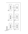
- FIG. 3 is a diagram illustrating an example of a functional configuration of the information processing apparatus 107.
- the information processing apparatus 107 includes an inspection control unit 301, an imaging control unit 302, an image processing unit 303, an output control unit 304, a communication unit 305, and a display control unit 306.
- the inspection control unit 301 acquires the information on the inspection order from the HIS / RIS 111.
- the examination order includes information on a patient who undergoes an examination and information on imaging procedures.
- the inspection control unit 301 transmits information related to the inspection order to the imaging control unit 302.
- the inspection control unit 301 displays information on the inspection on the display unit 109 in order to present information related to the inspection to the user via the display control unit 306.
- the information on the examination displayed on the display unit 109 includes information on the patient undergoing the examination, information on the imaging technique included in the examination, and an image already generated after imaging.
- the inspection control unit 301 transmits information regarding the progress of the inspection to the HIS / RIS 111 via the communication unit 305.
- the imaging control unit 302 controls the probe 103 based on the imaging procedure information received from the examination control unit 301, and acquires an ultrasonic signal and a photoacoustic signal from the probe 103 and the signal collection unit 104.
- the imaging control unit 302 instructs the irradiation unit 106 to irradiate light.
- the imaging control unit 302 instructs the transmission / reception unit 105 to transmit ultrasonic waves.
- the imaging control unit 302 executes an instruction to the irradiation unit 106 and an instruction to the transmission / reception unit 105 based on user operation input and information on imaging techniques. In addition, the imaging control unit 302 instructs the transmission / reception unit 105 to receive ultrasonic waves.
- the imaging control unit 302 instructs the signal collection unit 104 to sample a signal.
- the imaging control unit 302 controls the probe 103 as described above to distinguish and acquire an ultrasonic signal and a photoacoustic signal.
- the imaging control unit 302 acquires information (hereinafter referred to as timing information) regarding the timing at which the ultrasonic signal and the photoacoustic signal are acquired.
- the timing information is information indicating, for example, the timing of light irradiation or ultrasonic transmission by the imaging control unit 302 controlling the probe 103.
- the information indicating the timing may be a time or an elapsed time since the start of the inspection.
- the imaging control unit 302 acquires an ultrasonic signal and a photoacoustic signal converted into a digital signal output from the signal collection unit 104. That is, the imaging control unit 302 is an example of a signal acquisition unit that acquires an ultrasonic signal and a photoacoustic signal. The imaging control unit 302 is an example of an information acquisition unit that acquires timing information.
- the image processing unit 303 generates an ultrasonic image, a photoacoustic image, and a superimposed image obtained by superimposing the photoacoustic image on the ultrasonic image. Further, the image processing unit 303 generates a moving image including an ultrasonic image and a photoacoustic image.
- the image processing unit 303 generates a photoacoustic image based on the photoacoustic signal acquired by the imaging control unit 302.
- the image processing unit 303 reconstructs an acoustic wave distribution (hereinafter referred to as an initial sound pressure distribution) when light is irradiated based on the photoacoustic signal.
- the image processing unit 303 acquires the light absorption coefficient distribution in the subject by dividing the reconstructed initial sound pressure distribution by the light fluence distribution of the subject irradiated with the light. Further, the concentration distribution of the substance in the subject is obtained from the absorption coefficient distribution for a plurality of wavelengths by utilizing the fact that the degree of light absorption in the subject varies depending on the wavelength of the light irradiated to the subject.
- the image processing unit 303 acquires the concentration distribution of substances in the subject of oxyhemoglobin and deoxyhemoglobin. Further, the image processing unit 303 acquires the oxygen saturation distribution as a ratio of the oxyhemoglobin concentration to the deoxyhemoglobin concentration.
- the photoacoustic image generated by the image processing unit 303 is an image indicating at least one of the above-described initial sound pressure distribution, light fluence distribution, absorption coefficient distribution, substance concentration distribution, and oxygen saturation distribution, for example.
- the image processing unit 303 acquires a bright line obtained by converting the amplitude of the reflected wave of the ultrasonic signal into luminance, and changes the display position of the bright line in accordance with the scanning of the ultrasonic beam, thereby generating an ultrasonic image (B-mode image). Generate.
- the image processing unit 303 can generate an ultrasonic image (C mode image) including three orthogonal cross sections.
- the image processing unit 303 generates an arbitrary cross section or a rendered stereoscopic image based on the three-dimensional ultrasonic image.
- the image processing unit 303 is an example of an image acquisition unit that acquires an ultrasonic image and a photoacoustic image.
- the output control unit 304 generates an object for transmitting various types of information to an external device such as the PACS 112 and the Viewer 113 in accordance with the control from the inspection control unit 301 and the user's operation input.
- the object is information to be transmitted from the information processing apparatus 107 to an external apparatus such as the PACS 112 or the viewer 113.
- the output control unit 304 generates a DICOM object for outputting the ultrasonic image and the photoacoustic image generated by the image processing unit 303 and the superimposed image thereof to the PACS 112.
- the object output to the external device includes incidental information attached as various tags according to the DICOM standard.
- the incidental information includes, for example, patient information, information indicating the imaging device that captured the image, an image ID for uniquely identifying the image, and an examination ID for uniquely identifying the examination that captured the image , Information of the probe 103 is included.
- the incidental information generated by the output control unit 304 includes information that associates the ultrasonic image captured during the examination with the photoacoustic image.
- a moving image including an ultrasonic image and a photoacoustic image these may be acquired at different frame rates. For example, when the ultrasonic image is acquired at a higher frame rate, the photoacoustic image acquired at substantially the same timing as all the ultrasonic images does not necessarily exist.
- the output control unit 304 Based on the timing information acquired by the imaging control unit 302, the output control unit 304 associates a photoacoustic image with each of a plurality of ultrasonic images constituting the moving image. And the information which shows the photoacoustic image corresponding to each ultrasonic image is produced
- the output control unit 304 is an example of a processing unit that associates any photoacoustic image with an ultrasonic image.
- the communication unit 305 controls transmission / reception of information between the information processing apparatus 107 and an external apparatus such as the HIS / RIS 111, the PACS 112, and the Viewer 113 via the network 110.
- the transmission / reception control unit 128 receives the inspection order information from the HIS / RIS 111.
- the transmission / reception control unit 128 transmits the object generated by the image loss processing control unit 127 to the PACS 112 and the Viewer 113.
- the display control unit 306 controls the display unit 109 to display information on the display unit 109.
- the display control unit 306 displays information on the display unit 109 in response to an input from another module or a user operation input via the operation unit 108.
- the display control unit 306 is an example of a display control unit.
- FIG. 4 illustrates a process in which the information processing apparatus 107 captures a moving image including an ultrasonic image and a photoacoustic image, generates incidental information, and outputs an object including the moving image and the incidental information to an external apparatus. It is a flowchart which shows an example. In the following processing, unless otherwise specified, the main body that realizes each processing is the CPU 201 or the GPU. Information acquired by the information processing apparatus 107 will be described with reference to FIGS. 5 to 7 as appropriate.
- step S401 the inspection control unit 301 receives an instruction to start imaging.
- the inspection control unit 301 acquires inspection order information from the HIS / RIS 111.
- the display control unit 306 causes the display unit 109 to display inspection information indicated by the inspection order and a user interface for the user to input an instruction for the inspection.
- Shooting is started by a shooting start instruction input to the user interface via the operation unit 108.
- shooting of a moving image composed of an ultrasonic image and a photoacoustic image is started.
- the imaging control unit 302 controls the probe 103 and the signal collecting unit 104 to start imaging an ultrasonic image.
- the user presses the probe 103 against the subject 101 and images a desired position.
- the imaging control unit 302 acquires an ultrasonic signal that is a digital signal and timing information related to acquisition of the ultrasonic signal, and stores them in the RAM 203.
- the image processing unit 303 generates an ultrasonic image by performing processing such as phasing addition (Delay and Sum) on the ultrasonic signal. Note that when the ultrasonic image is generated, the ultrasonic signal stored in the RAM 203 may be deleted.
- the image processing unit 303 causes the display unit 109 to display the acquired ultrasonic image via the display control unit 306.
- the imaging control unit 302 and the image processing unit 303 repeatedly execute these processes and update the ultrasound image displayed on the display unit 109. Thereby, an ultrasonic image is displayed as a moving image.
- the imaging control unit 302 controls the probe 103 and the signal collecting unit 104 to start imaging a photoacoustic image.
- the user presses the probe 103 against the subject 101 and images a desired position.
- the imaging control unit 302 acquires a photoacoustic signal that is a digital signal and timing information related to acquisition of the photoacoustic signal, and stores them in the RAM 203.
- the image processing unit 303 generates a photoacoustic image by performing a process such as Universal Back-Projection (UBP) on the photoacoustic signal. Note that when the photoacoustic image is generated, the photoacoustic signal stored in the RAM 203 may be deleted.
- UBP Universal Back-Projection
- the image processing unit 303 displays the acquired photoacoustic image on the display unit 109 via the display control unit 306.
- the imaging control unit 302 and the image processing unit 303 repeatedly execute these processes and update the photoacoustic image displayed on the display unit 109. Thereby, a photoacoustic image is displayed as a moving image.
- step S402 and step S403 may be performed simultaneously, may be switched at predetermined intervals, or may be switched based on a user operation input or an inspection order.
- the photoacoustic image may be captured first.
- the display control unit 306 may display one image superimposed on the other image, or may display the images side by side.
- the image processing unit 303 may acquire a superimposed image obtained by superimposing the ultrasonic image and the photoacoustic image, and the display control unit 306 may cause the display unit 109 to display the superimposed image.
- step S404 the output control unit 304 associates the ultrasonic image acquired in steps S402 and S403 with the photoacoustic image, and stores them in the storage device 204 together with the accompanying information.
- step S404 the output control unit 304 repeats the ultrasonic image and the photoacoustic image of each frame acquired in steps S402 and S403, thereby moving the moving image including the ultrasonic image and the photoacoustic image. It can be saved as an image file.
- FIG. 5 is a diagram illustrating an example of a data configuration acquired in step S404.
- the saved data 501 is saved in the storage device 204 in step S404.
- the saved data 501 includes incidental information 502 and image data 503.
- the incidental information 502 is recorded in the header portion of the saved data 501.
- Image data 503 includes ultrasonic images 508 to 511 and photoacoustic images 512 to 513 acquired in steps S402 and S403.
- identifiers U1 to U4 for uniquely identifying each of the ultrasonic images 508 to 511 are attached.
- the photoacoustic images 512 to 513 are assigned identifiers P1 to P2 for uniquely identifying each of them.
- the incidental information 502 includes subject information 504 that represents the attributes of the subject 101 and probe information 505 that is information of the probe 103 used for imaging.
- the subject information 504 includes at least one piece of information such as a subject ID, subject name, age, blood pressure, heart rate, body temperature, height, weight, pre-existing condition, pregnancy week, and examination information.
- the examination system 102 includes an electrocardiograph (not shown) or a pulse oximeter (not shown), information about the electrocardiogram and oxygen saturation may be stored as the subject information 504.
- the probe information 505 includes information related to the probe 103 such as the type of the probe 103 and the position and inclination at the time of imaging.
- the inspection system 102 may include a magnetic sensor (not shown) that detects the position and inclination of the probe 103, and the imaging control unit 302 may acquire such information from the magnetic sensor (not shown).
- the incidental information 502 includes timing information 506 of the ultrasonic signals related to the ultrasonic images 508 to 511 and the photoacoustic signals related to the photoacoustic images 512 to 513 stored in step S404.
- Timing information 506 is acquired in step S402 and step S403 as described above.
- the timing information is indicated by, for example, the time or the elapsed time from the start of the inspection as described above.
- the timing information of the ultrasound image is information related to the timing at which the ultrasound signal used for the ultrasound image is acquired.
- the timing information when a plurality of ultrasonic signals are used for one ultrasonic image may be information related to the timing at which an arbitrary ultrasonic signal is acquired, and can be used for each ultrasonic image acquired in one inspection. It only needs to be unified.
- the timing at which the ultrasonic signal is acquired may be the timing at which the information processing apparatus 107 receives the ultrasonic signal, the timing at which the probe 103 transmits the ultrasonic wave to the subject 101, or the probe 103 receives the ultrasonic wave.
- the timing at which the ultrasonic wave transmission / reception drive signal for the probe 103 is detected may be the timing at which the signal collection unit 104 receives the ultrasonic signal.
- the timing information of the photoacoustic image is information related to the timing at which the photoacoustic signal used for the photoacoustic image is acquired.
- Timing information in the case where a plurality of photoacoustic signals are used for one photoacoustic image may be information related to the timing at which an arbitrary photoacoustic signal is acquired, and can be operated on each photoacoustic image acquired in one inspection. It only needs to be unified.
- the timing at which the photoacoustic signal is acquired may be the timing at which the information processing apparatus 107 receives the photoacoustic signal, the timing at which the probe 103 irradiates the subject 101 with light, or the probe 103 has received the photoacoustic.
- the timing may be the timing at which the drive signal for the probe 103 for light irradiation or photoacoustic reception is detected, or the timing at which the signal collection unit 104 receives the photoacoustic signal.
- the incidental information 502 includes correspondence information 507 that is information for associating the ultrasonic images 508 to 511 and the photoacoustic images 512 to 513.
- the correspondence information 507 includes information on the photoacoustic image associated with each of the ultrasonic images acquired at a frame rate higher than that of the photoacoustic image.
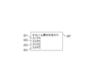
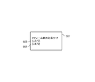
- FIG. 6 is a diagram illustrating an example of the correspondence information 507.
- (Um, Pn) recorded in each of the rows 601 to 604 indicates that the frame Pm of the photoacoustic image is associated with the frame Um of the ultrasonic image.
- each frame of the ultrasonic image acquired by one inspection is associated with at least one photoacoustic image frame among the photoacoustic images acquired by the inspection.
- the plurality of frames are obtained for each frame of the ultrasonic image.
- Frames of photoacoustic images may be associated with each other.
- the frame Um of the ultrasonic image may be associated with the frames Px, Py, Pz of the photoacoustic image (Um, Px, Py, Pz).
- step S405 the shooting control unit 302 receives an instruction to end shooting.
- the display control unit 306 displays a user interface for the user to input an instruction on the display unit 109.
- the imaging control unit 302 ends imaging based on an instruction to end imaging input to the user interface via the operation unit 108. Further, the imaging control unit 302 may determine that the imaging has ended when a predetermined time has elapsed from the imaging start instruction received in step S401.
- the inspection control unit 301 transmits information indicating that the imaging is completed to the HIS / RIS 111 via the communication unit 305.
- step S406 the imaging control unit 302 controls the probe 103 to end the imaging of the ultrasonic image and the photoacoustic image.
- step S407 the output control unit 304 ends the processing for storing the ultrasonic image and the photoacoustic image started in step S404.
- step S408 the output control unit 304 outputs a moving image including the ultrasonic image and the photoacoustic image acquired in steps S402 and S403 to an external device based on the information stored up to step S407. Create an object for.
- the communication unit 305 outputs the object to an external device such as the PACS 112.
- FIG. 7 is a diagram illustrating an example of the object generated in step S408.
- the DICOM object 701 includes incidental information 702 and image data 703.
- the auxiliary information 702 and the image data 703 are illustrated separately for simplicity, but the auxiliary information 702 may be described in, for example, a header portion of the image data 703.
- the incidental information 702 includes subject information 704, probe information 705, and correspondence information 706.
- the object information 704 corresponds to the object information 504 shown in FIG.
- the probe information 705 corresponds to the probe information 505 shown in FIG.
- the correspondence information 706 corresponds to the correspondence information 507 shown in FIG.
- Each piece of information included in the incidental information 702 may include the same information as the corresponding pieces of information illustrated in FIG. 5, or may include only information that is essential in the DICOM standard. Only predetermined items that are arbitrarily set may be included.
- the subject information 704 may be only information indicating the subject ID, age, sex, and examination ID.
- the incidental information 702 may not include the probe information 705. Further, the incidental information 702 may further include timing information corresponding to the timing information 506 shown in FIG.
- the image data 703 includes ultrasonic images 707 to 710 and photoacoustic images 711 to 714.
- photoacoustic images 711 to 714 are associated as overlay images for the ultrasonic images 707 to 710, respectively.
- both the photoacoustic image 711 and the photoacoustic image 712 are the photoacoustic image P1
- the photoacoustic image 712 may be replaced with the photoacoustic image P1
- only the information which shows the photoacoustic image P1 may be included. That is, information indicating that the photoacoustic image corresponding to the ultrasonic image 708 is the photoacoustic image P ⁇ b> 1 only needs to be included in the DICOM object 701.
- the information is, for example, correspondence information 706.
- the photoacoustic image may be separated from the DICOM object 701 and used as another DICOM object such as CSPS (Color Softcopy Presentation State).
- CSPS Color Softcopy Presentation State
- the output control unit 304 may convert the photoacoustic image into an annotation object.
- a superimposed image of an ultrasonic image and a photoacoustic image may be used as a Secondary Capture.
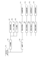
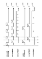
- FIG. 8 is a timing chart of processing related to acquisition of an ultrasonic image and a photoacoustic image.
- Each of the diagrams 801 to 806 indicates that time elapses when proceeding to the right in the drawing.
- Times t1, t2, t3, and t4 indicate the rising or falling time of each diagram in each timing chart.
- the rise or fall of the diagram is simply referred to as rise or fall.
- Diagram 801 represents timing related to acquisition of ultrasonic signals.
- the probe 103 starts transmitting ultrasonic waves to the subject 101, and the acquired reflected waves are appropriately transmitted to the information processing apparatus 107 as ultrasonic signals.
- the imaging control unit 302 ends the reception of the ultrasonic signal.
- Frames U1 to U4 correspond to the frames of the ultrasonic image. For example, in frame U1, the probe 103 transmits an ultrasonic wave to the subject 101 at time t1, and the imaging control unit 302 ends reception of the ultrasonic signal at time t2.
- Diagram 802 represents timing related to acquisition of an ultrasound image.
- the image processing unit 303 starts generating an ultrasonic image.
- the image processing unit 303 completes the generation of the ultrasonic image, and the information processing apparatus 107 acquires the ultrasonic image.
- the image processing unit 303 starts generating an ultrasound image at time t2
- the image processing unit 303 ends generating the ultrasound image at time t3.
- Diagram 803 represents the timing related to the display of the ultrasonic image.
- the display control unit 306 starts display of the frame U1 at time t4, and performs display by sequentially switching the frames to the frames U2, U3, and U4 at a predetermined rate.
- the process of step S402 illustrated in FIG. 4 corresponds to diagrams 801, 802, and 803.
- Diagram 804 represents timing related to acquisition of the photoacoustic signal.
- the probe 103 starts irradiating the subject 101 with light, and the acquired photoacoustic is appropriately transmitted to the information processing apparatus 107 as a photoacoustic signal.
- the imaging control unit 302 ends the reception of the photoacoustic signal.
- P1 and P2 correspond to each frame of the photoacoustic image. For example, in frame P1, the probe 103 irradiates the subject 101 with light at time t2, and the imaging control unit 302 ends reception of the photoacoustic signal at time t3.
- Diagram 805 represents timing related to acquisition of the photoacoustic image.
- the image processing unit 303 starts generating a photoacoustic image.
- the image processing unit 303 finishes generating the photoacoustic image, and the information processing apparatus 107 acquires the photoacoustic image.
- the image processing unit 303 starts generating a photoacoustic image at time t3, and the image processing unit 303 ends generating the photoacoustic image at time t4.
- Diagram 806 represents the timing related to the display of the photoacoustic image.
- the display control unit 306 starts displaying the frame P1 at time t4, and switches the frame to the frame P2 at a predetermined rate to display.
- the process of step S403 illustrated in FIG. 4 corresponds to diagrams 804, 805, and 806.
- the ultrasonic image is displayed at a frame rate twice that of the photoacoustic image.
- FIG. 9 is a flowchart illustrating an example of processing in which the output control unit 304 associates the ultrasonic image and the photoacoustic image acquired in the examination. That is, the process shown in FIG. 9 is executed in step S404 in FIG.
- the output control unit 304 outputs either the first photoacoustic image acquired at the first time point or the second photoacoustic image acquired at the second time point after the first time point.
- the output control unit 304 selects one of the first photoacoustic image and the second photoacoustic image based on the relationship between the first time point, the second time point, and the third time point. Associate.
- the main body that realizes each processing is the CPU 201 or the GPU.
- step S901 the output control unit 304 sets a temporary variable U representing the frame of the ultrasonic image to the frame of the first ultrasonic image.
- the output control unit 304 identifies the first ultrasonic image frame based on the timing information.
- the first ultrasonic image is, for example, an ultrasonic image generated based on the first acquired ultrasonic signal. Below, let the acquisition time of an ultrasonic image be the acquisition time of the ultrasonic signal used for the production
- the output control unit 304 sets a temporary variable P representing the frame of the photoacoustic image to the frame of the first photoacoustic image.
- the output control unit 304 identifies the frame of the first photoacoustic image based on the timing information.
- the first photoacoustic image is a photoacoustic image generated based on the photoacoustic signal acquired first, for example. Below, let the acquisition time of a photoacoustic image be the acquisition time of the photoacoustic signal used for the production
- the output control unit 304 obtains a photoacoustic image frame P having an acquisition time closest to the acquisition time of U for each frame U of the ultrasonic image, and corresponds P to U. Put it on. That is, in the first embodiment, the ultrasonic image is associated with the photoacoustic image having the closest acquired time.
- step S903 the output control unit 304 acquires frame information of the photoacoustic image acquired at a time later than the acquisition time of the frame P set in step S902. If there is a frame acquired at a time later than the acquisition time of the frame P, the process proceeds to step S904, and if not, the process proceeds to S907.
- the acquisition time of the frame P is an example of a first time point.
- step S904 the output control unit 304 sets the temporary variable P ′ representing the frame of the photoacoustic image to the frame of the photoacoustic image acquired immediately after the frame P.
- the acquisition time of the frame P ′ is an example of a second time point.
- step S905 the output control unit 304 compares the acquisition times of the frame P ′ and the frame P. If the acquisition time tp ′ of the frame P ′ is closer to the acquisition time tu of the frame U than the acquisition time tp of the frame P, that is, if
- step S906 the output control unit 304 sets the temporary variable P representing the frame of the photoacoustic image to the frame in which P ′ is set in step S904, and the process proceeds to step S903.
- step S907 the output control unit 304 associates the frame P of the photoacoustic image with the frame U of the ultrasonic image, and proceeds to step S908.
- step S908 the output control unit 304 acquires frame information of the ultrasonic image acquired at a time later than the acquisition time of the frame U. If there is a frame acquired at a time later than the acquisition time of the frame U, the process proceeds to step S909, and if not, the process shown in FIG.
- step S909 the output control unit 304 sets the temporary variable U representing the frame of the ultrasonic image to the ultrasonic image acquired immediately after the ultrasonic image set in step S901 or the frame U in step S909 of the immediately preceding loop.
- the frame is set, and the process proceeds to S903.
- the photoacoustic image with the first acquisition time is associated with the ultrasonic image.
- the acquisition time of the ultrasonic image may be separated from the acquisition time of the first photoacoustic image.
- Associating images at different acquisition times may be inappropriate when a doctor observes a moving image.
- the output control unit 304 may acquire the value of tp-tu, and if greater than a predetermined threshold value, the frame P and the frame U may not be associated in step S907.
- the output control unit 304 may acquire the value of tu-tp, and if greater than a predetermined threshold value, the frame P and the frame U may not be associated in step S907.
- the photoacoustic images acquired before and after the acquisition time of the frame U when there are photoacoustic images acquired before and after the acquisition time of the frame U, the photoacoustic images acquired at a time close to the acquisition time of the frame U among the preceding and following photoacoustic images.
- the acquisition time of the frame U is an example of a third time point between the first time point and the second time point.
- FIG. 9 shows an example of processing in which one photoacoustic image frame is associated with each frame of the ultrasonic image
- the output control unit 304 uses a plurality of types of light for each frame of the ultrasonic image. Processing may be performed so as to associate the frames of the acoustic image.
- the Viewer 113 may display a moving image in which frames of a plurality of types of photoacoustic images are associated with each type of photoacoustic image superimposed.
- FIG. 9 shows an example of processing in the case of associating the frame P of the photoacoustic image having the acquisition time closest to the acquisition time of the ultrasonic image frame U, but the output control unit 304 sets the acquisition time of the frame U.
- You may match the frame of the photoacoustic image with the acquisition time immediately before or immediately after. That is, regardless of whether or not it has the acquisition time closest to the acquisition time of the ultrasound image frame U, the frame of the photoacoustic image having the acquisition time within the predetermined time before and after is correlated with the acquisition time of the frame U as a reference. Also good.
- the image processing unit 303 generates an interpolation frame P from a plurality of photoacoustic image frames acquired before and after the acquisition time of the ultrasound image frame U, and the output control unit 304 corresponds the interpolation frame P to the frame U. It may be attached.
- the image processing unit 303 may generate the complement frame P only when the difference between the two photoacoustic images is equal to or less than the threshold value.
- the output control unit 304 processes the ultrasonic image and the photoacoustic image acquired at the timing shown in FIG. 8 according to the flow of FIG. 9, the photoacoustic image P1 is displayed in the ultrasonic images U1 and U2.
- the photoacoustic image P2 is matched with the images U3 and U4, respectively.
- the display control unit 306 causes the display unit 109 to display a superimposed image in which the photoacoustic image P1 is superimposed on the ultrasonic image U1 or the ultrasonic image U2.
- step S ⁇ b> 404 the output control unit 304 associates the photoacoustic image frame P ⁇ b> 1 with the ultrasonic image frame U ⁇ b> 1 and the ultrasonic image frame U ⁇ b> 2 and stores them in the correspondence information 507.
- step S ⁇ b> 408 the communication unit 305 transmits the DICOM object 701 including the associated image data 703 to the PACS 112.
- a frame of the photoacoustic image is associated with each frame of the ultrasonic image. It is also possible to reduce the frame rate of the ultrasound image so that it matches the frame rate of the photoacoustic image. It will go down. However, in the present embodiment, it is possible to associate both images while maintaining the frame rate of the ultrasonic image.
- the user causes the DICOM object 701 to be displayed using the Viewer 113 connected to the PACS 112. At that time, the Viewer 113 can display both the ultrasonic image and the photoacoustic image based on the correspondence information 706 included in the DICOM object 701. Since at least one photoacoustic image is associated with each ultrasonic image, even when the frame rates of the ultrasonic image and the photoacoustic image are different, display flicker in the moving image can be reduced.
- the configuration of the inspection system 102 including the information processing device 107 according to the second embodiment, the hardware configuration of the information processing device 107, and the functional configuration of the information processing device 107 are the same as the examples shown in FIGS. It is the same. Detailed description is omitted here by using the above description for the common parts.
- the output control unit 304 stores the timing of the instruction in the timing information according to the storage instruction input by the user via the operation unit 108, and stores the image data and the incidental information. To do. Further, a storage instruction is transmitted to the output control unit 304 in response to the image processing unit 303 obtaining the image data, and the output control unit 304 includes the above-described timing information in response to the instruction from the image processing unit 303. Information and image data may be stored.
- the information processing apparatus 107 captures a moving image composed of an ultrasonic image and a photoacoustic image, generates incidental information based on a storage instruction, and sets an object including the moving image and the incidental information as an external object. It is a flowchart which shows an example of the process output to an apparatus. In the following processing, unless otherwise specified, the main body that realizes each processing is the CPU 201 or the GPU. Information acquired by the information processing apparatus 107 will be described with reference to FIGS. 11 to 13 as appropriate.
- steps S1001 to S1003 is the same as the processing in steps S401 to S403 shown in FIG.
- step S1004 the shooting control unit 302 receives an instruction to end shooting.
- the imaging control unit 302 receives the instruction in the same process as step S405 shown in FIG.
- the process advances to step S1009, and the inspection control unit 301 transmits information indicating that the imaging is completed to the HIS / RIS 111 via the communication unit 305. If there is no instruction to end shooting, the process advances to step S1005.
- step S1005 the output control unit 304 receives an instruction to start saving.
- the user can input the instruction via the user interface displayed on the display unit 109 by the display control unit 306 during the examination. Further, the user may input an instruction to start saving to the output control unit 304 via an input unit (not shown) such as a freeze button provided in the probe 103.
- an input unit not shown
- the process proceeds to step S1006, and when there is no instruction, the process proceeds to step S1004.
- step S1006 the output control unit 304 associates the ultrasonic image and the photoacoustic image acquired in steps S1002 and S1003, and stores them in the storage device 204 together with the accompanying information.
- the output control unit 304 performs processing on each of the ultrasonic image and the photoacoustic image of each frame acquired in steps S1002 and S1003, and a moving image including the ultrasonic image and the photoacoustic image. Can be saved as a file.
- step S1004 and subsequent steps the processing in steps S1002 and S1003 may be continued, and the above-described processing may be repeatedly performed on the ultrasonic image and the photoacoustic image newly acquired in step S1006.
- FIG. 11 is a diagram illustrating an example of the configuration of data acquired in step S1006.
- the same components as those in the example shown in FIG. 5 are denoted by the same reference numerals, and detailed description thereof will be omitted by using the above description.
- the timing information 506 further includes information related to the timing at which the storage instruction is issued.
- FIG. 12 is a diagram showing an example of the correspondence information 507 in FIG.
- the same components as those in the example shown in FIG. 6 are denoted by the same reference numerals, and detailed description thereof will be omitted by using the above description.
- correspondence information regarding the frame after the save instruction is described.
- step S1007 the output control unit 304 receives an instruction to stop saving.
- the process advances to step S1008.
- the user can input the instruction via the user interface displayed on the display unit 109 by the display control unit 306 during the examination. Further, the user may input via an input unit (not shown) such as a freeze button provided on the probe 103.
- an input unit not shown
- the process proceeds to step S1008.
- step S1008 the output control unit 304 ends the processing related to the storage of the ultrasonic image and the photoacoustic image started in step S1006.
- step S1009 the imaging control unit 302 controls the probe 103 to end the imaging of the ultrasonic image and the photoacoustic image.
- step S1010 the output control unit 304 outputs a moving image including the ultrasonic image and the photoacoustic image acquired in steps S1002 and S1003 to an external device based on the information stored up to step S1009. Create an object for.
- the communication unit 305 outputs the object to an external device such as the PACS 112.
- FIG. 13 is a diagram illustrating an example of the object generated in step S1010.
- the same components as those in the example shown in FIG. 7 are denoted by the same reference numerals, and detailed description thereof will be omitted by using the above description.
- the incidental information 702 may further include information related to the timing at which the storage instruction is given.
- step S1004 to step S1008 may be repeatedly instructed.
- the output control unit 304 may store different storage data 501 in the storage device 204 each time the process of step S1006 is executed, or may store one storage data 501 through repetition.
- the output control unit 304 may convert one storage data 501 into one DICOM object 701 in step S1010.
- the output control unit 304 may convert a plurality of stored data 501 into a single DICOM object 701.
- FIG. 14 is a timing chart of processing related to acquisition of an ultrasonic image and a photoacoustic image.
- Each of the diagrams 1401 to 1407 indicates that time elapses when proceeding to the right in the drawing.
- Times t5, t6, t7, and t8 indicate rising or falling times in the respective timing charts.
- Diagrams 1401 to 1406 relate to the same processing as the diagrams 801 to 806 shown in FIG.
- the probe 103 starts transmitting ultrasonic waves to the subject 101, and at time t7, the imaging control unit 302 ends receiving ultrasonic signals.
- the probe 103 starts irradiating the subject 101 with light.
- the diagram 1407 represents the timing related to the storage instruction.
- the imaging control unit 302 receives an instruction to start saving based on, for example, a user operation input at time t5, and receives an instruction to end saving at time t8.
- FIG. 15 is a flowchart illustrating an example of processing in which the output control unit 304 associates the ultrasonic image and the photoacoustic image acquired in the examination. That is, the process shown in FIG. 15 is executed in step S1006 in FIG. In the following processing, unless otherwise specified, the main body that realizes each processing is the CPU 201 or the GPU.
- step S1501 the output control unit 304 sets the variables ts and te representing time to the time when the instruction to start saving is received and the time when the instruction to end saving is received. If the control unit 304 has not received an instruction to end saving, the value of the variable te may not be set, or may be set to an arbitrary value that is determined to be Yes in step S1504 described later. It is good to do.
- step S1502 the temporary variable U representing the frame of the ultrasonic image is set to the frame of the first ultrasonic image after the acquisition time ts.
- the output control unit 304 specifies the frame of the first ultrasound image whose acquisition time is after ts based on the timing information.
- step S1503 the temporary variable P representing the frame of the photoacoustic image is set to the frame of the first photoacoustic image whose acquisition time is after ts.
- the output control unit 304 specifies the frame of the first photoacoustic image whose acquisition time is after ts based on the timing information.
- the output control unit 304 starts from the time ts having the acquisition time closest to the acquisition time of U for each frame U of the ultrasonic image captured between the time ts and the time te. A frame P of the photoacoustic image photographed during time te is obtained. Then, P is associated with U.
- step S1504 the output control unit 304 acquires information regarding the acquisition times of the frame U and the frame P. If the respective acquisition times are before te, the process proceeds to step S1505. If the acquisition times include those after te, the processing shown in FIG. 15 ends. If the control unit 304 has not received an instruction to end the storage and the value of the variable te is not set, the process proceeds to step S1505.
- step S1505 the output control unit 304 acquires frame information of the photoacoustic image acquired at a time later than the acquisition time of the frame P set in step S1503. If there is a frame acquired at a time later than the acquisition time of the frame P, the process proceeds to step S1506, and if not, the process proceeds to S1510.
- step S1506 the output control unit 304 sets the temporary variable P ′ representing the frame of the photoacoustic image to the frame of the photoacoustic image acquired immediately after the frame P.
- step S1507 the output control unit 304 acquires information regarding the acquisition time of the frame P ′. If the acquisition time of the frame P ′ is before te, the process proceeds to step S1508, and if it is after te, the process proceeds to step S1510. If the control unit 304 has not received an instruction to end the storage and the value of the variable te is not set, the process proceeds to step S1508.
- step S1508 the output control unit 304 compares the acquisition times of the frame P ′ and the frame P. If the acquisition time tp ′ of the frame P ′ is closer to the acquisition time tu of the frame U than the acquisition time tp of the frame P, that is, if
- step S1509 the output control unit 304 sets the temporary variable P representing the frame of the photoacoustic image to the frame set to P ′ in step S1506, and the process proceeds to step S1505.
- step S1510 the output control unit 304 associates the frame P of the photoacoustic image with the frame U of the ultrasonic image, and proceeds to step S1511.
- step S1511 the output control unit 304 acquires information on the frame of the ultrasonic image acquired at a time later than the acquisition time of the frame U. If there is a frame acquired at a time later than the acquisition time of the frame U, the process proceeds to step S1512. If not, the process shown in FIG. 15 ends.
- step S1512 the output control unit 304 sets the temporary variable U representing the frame of the ultrasonic image to the ultrasonic image acquired immediately after the ultrasonic image set in step S1502 or the frame U in step S1512 of the immediately preceding loop.
- the frame is set, and the process proceeds to step S1504.
- the output control unit 304 processes the ultrasonic image and the photoacoustic image acquired at the timing illustrated in FIG. 14 according to the flow illustrated in FIG. 15, the ultrasonic image U3 and the ultrasonic image acquired after the instruction to start storage are displayed.
- a photoacoustic image P2 is associated with each of the sound wave images U4.
- the display control unit 306 causes the display unit 109 to display a superimposed image in which the photoacoustic image P1 is superimposed on the ultrasonic image U1 or the ultrasonic image U2.
- the display control unit 306 causes the display unit 109 to display a superimposed image in which the photoacoustic image P2 is superimposed on the ultrasonic image U3 or the ultrasonic image U4.
- the output control unit 304 detects the ultrasonic image U ⁇ b> 3, the ultrasonic image U ⁇ b> 4, and the photoacoustic imaged between the time ts at which an instruction to start saving is given and the time te at which an instruction to end saving is given.
- the image frame P2 is associated and stored in the correspondence information 507.
- the communication unit 305 transmits a DICOM object 701 including the associated image data 703 to the PACS 112.
- the user captures an ultrasonic image and a photoacoustic image, observes the superimposed image displayed on the display unit 109, and stores the ultrasonic image acquired during the period instructed to save.
- Each frame can be associated with a frame of the photoacoustic image. Then, when the output DICOM object 701 is reproduced on the Viewer 113, display flicker in the moving image is reduced even when the frame rates of the ultrasonic image and the photoacoustic image are different.
- the photoacoustic image when a photoacoustic image is included in a part of a moving image composed of a series of ultrasonic images based on information related to a user's operation input, the photoacoustic image is reproduced when the moving image is reproduced.
- the purpose is to be able to quickly identify the section including the.
- the configuration of the inspection system 102 including the information processing apparatus 107 according to the third embodiment, the hardware configuration of the information processing apparatus 107, and the functional configuration of the information processing apparatus 107 are the same as those shown in FIGS. 1, 2, and 3, respectively. It is the same. Detailed description is omitted here by using the above description for the common parts.
- the imaging control unit 302 acquires information related to user operation input (hereinafter referred to as operation information) based on information from the probe 103 and information input via the operation unit 108. To do.
- the output control unit 304 acquires incidental information including operation information.
- FIG. 16 illustrates a process in which the information processing apparatus 107 captures a moving image including an ultrasonic image and a photoacoustic image, generates auxiliary information, and outputs an object including the moving image and the auxiliary information to an external device.
- a case will be described as an example in which a photoacoustic image is also taken based on a user operation input while an ultrasonic image is being taken.
- the main body that realizes each processing is the CPU 201 or the GPU.
- information acquired by the information processing apparatus 107 will be described with reference to FIGS. 5, 6, 17, 18, and 9 as appropriate.
- step S1601 the inspection control unit 301 receives an instruction to start imaging.
- the inspection control unit 301 acquires inspection order information from the HIS / RIS 111.
- the display control unit 306 causes the display unit 109 to display inspection information indicated by the inspection order and a user interface for the user to input an instruction for the inspection.
- Shooting is started by a shooting start instruction input to the user interface via the operation unit 108.
- Imaging of an ultrasonic image is started based on a user operation input or automatically.
- the imaging control unit 302 controls the probe 103 and the signal collection unit 104 to start imaging an ultrasonic image.
- the user presses the probe 103 against the subject 101 and images a desired position.
- the imaging control unit 302 acquires an ultrasonic signal that is a digital signal and timing information related to acquisition of the ultrasonic signal, and stores them in the RAM 203.
- the image processing unit 303 generates an ultrasonic image by performing processing such as phasing addition (Delay and Sum) on the ultrasonic signal. Note that when the ultrasonic image is generated, the ultrasonic signal stored in the RAM 203 may be deleted.
- the image processing unit 303 causes the display unit 109 to display the acquired ultrasonic image via the display control unit 306.
- the imaging control unit 302 and the image processing unit 303 repeatedly execute these processes and update the ultrasound image displayed on the display unit 109. Thereby, an ultrasonic image is displayed as a moving image.
- step S1603 the output control unit 304 starts processing for storing the image data acquired by the image processing unit 303 and the accompanying information.
- the instruction to start saving is performed by an operation input to the information processing apparatus 107 or the probe 103 as described in the second embodiment, for example.
- step S1604 the imaging control unit 302 receives an instruction to end ultrasonic imaging.
- the display control unit 306 causes the display unit 109 to display a user interface for performing an operation input related to the inspection.
- the user can give an instruction to end ultrasonic imaging by an operation input on the user interface.
- an instruction to end ultrasonic imaging can be given by an operation input to an input unit (not shown) of the probe 103. If an end instruction is accepted, the process proceeds to step S1611. If there is no instruction, the process proceeds to step S1605.
- step S1605 the imaging control unit 302 receives an instruction to start photoacoustic imaging.
- the user can give an instruction to start photoacoustic imaging by an operation input on the user interface related to the inspection or an operation input on the probe 103. If a start instruction is accepted, the process proceeds to step S1606. If there is no instruction, the process proceeds to step S1607.
- step S1604 and step S1605 the imaging control unit 302 receives a user operation input instructing storage of an ultrasonic image and a photoacoustic image. From this viewpoint, the imaging control unit 302 is an example of a reception unit.
- step S1606 the imaging control unit 302 controls the probe 103 and the signal collecting unit 104 to start imaging a photoacoustic image.
- the user presses the probe 103 against the subject 101 and images a desired position.
- the imaging control unit 302 acquires a photoacoustic signal that is a digital signal and timing information related to acquisition of the photoacoustic signal, and stores them in the RAM 203.
- the image processing unit 303 generates a photoacoustic image by performing a process such as Universal Back-Projection (UBP) on the photoacoustic signal. Note that when the photoacoustic image is generated, the photoacoustic signal stored in the RAM 203 may be deleted.
- UBP Universal Back-Projection
- the image processing unit 303 displays the acquired photoacoustic image on the display unit 109 via the display control unit 306.
- the imaging control unit 302 and the image processing unit 303 repeatedly execute these processes and update the photoacoustic image displayed on the display unit 109. Thereby, a photoacoustic image is displayed as a moving image. Note that the process proceeds from step S1606 to step S1604, and when the imaging control unit 302 receives an instruction to end ultrasonic imaging in step S1604, the imaging control unit 302 controls the probe 103 to capture a photoacoustic image. finish.
- step S1607 the imaging control unit 302 receives an instruction to end photoacoustic imaging.
- the user can give an instruction to end photoacoustic imaging by an operation input on the user interface related to the inspection or an operation input on the probe 103. If an end instruction is accepted, the process proceeds to step S1608, and if there is no instruction, the process proceeds to step S1609.
- step S1605 and step S1607 since the user performs an operation input related to the photoacoustic image capturing, the imaging control unit 302 acquires operation information.
- step S1608 the imaging control unit 302 controls the probe 103 to finish imaging the photoacoustic image.
- step S1609 the shooting control unit 302 receives an instruction to shoot a still image.
- the user can instruct to take a still image by an operation input on the user interface related to the inspection or an operation input on the probe 103.
- the still image may be a still image of an ultrasonic image, a still image of a photoacoustic image, or a still image of a superimposed image in which a photoacoustic image is superimposed on an ultrasonic image. It may be. If an instruction to shoot a still image is accepted, the process proceeds to step S1610. If there is no instruction, the process proceeds to step S1604.
- step S1610 the imaging control unit 302 controls the probe 103 and the signal collecting unit 104 to execute a process of capturing a still image.
- the imaging control unit 302 controls the probe 103 and the signal collection unit 104 under conditions such as a specific operation mode for capturing a still image and a sampling cycle.
- the process for the image processing unit 303 to acquire the ultrasonic image and the photoacoustic image is the same as the process described in step S1602 and step S1608.
- the imaging control unit 302 acquires timing information of the ultrasonic image and the photoacoustic image.
- the timing information of the ultrasound image is information related to the timing at which the ultrasound signal used for the ultrasound image is acquired.
- the timing information when a plurality of ultrasonic signals are used for one ultrasonic image may be information related to the timing at which an arbitrary ultrasonic signal is acquired, and can be used for each ultrasonic image acquired in one inspection. It only needs to be unified.
- the timing at which the ultrasonic signal is acquired may be the timing at which the information processing apparatus 107 receives the ultrasonic signal, the timing at which the probe 103 transmits the ultrasonic wave to the subject 101, or the probe 103 receives the ultrasonic wave.
- the timing at which the ultrasonic wave transmission / reception drive signal for the probe 103 is detected may be the timing at which the signal collection unit 104 receives the ultrasonic signal.
- the timing information of the photoacoustic image is information related to the timing at which the photoacoustic signal used for the photoacoustic image is acquired. Timing information in the case where a plurality of photoacoustic signals are used for one photoacoustic image may be information related to the timing at which an arbitrary photoacoustic signal is acquired, and can be operated on each photoacoustic image acquired in one inspection. It only needs to be unified.
- the timing at which the photoacoustic signal is acquired may be the timing at which the information processing apparatus 107 receives the photoacoustic signal, the timing at which the probe 103 irradiates the subject 101 with light, or the probe 103 has received the photoacoustic.
- the timing may be the timing at which the drive signal for the probe 103 for light irradiation or photoacoustic reception is detected, or the timing at which the signal collection unit 104 receives the photoacoustic signal.
- the output control unit 304 When the output control unit 304 captures both the ultrasonic image and the photoacoustic image by the processing described in the first embodiment and the second embodiment, the output control unit 304 outputs light to each of the ultrasonic images. A process of associating the acoustic image is performed.
- step S1611 the output control unit 304 stores the information acquired from step S1603 to step S1611, and ends the processing related to the storage.
- FIG. 5 is a diagram illustrating an example of a configuration of data acquired in the processing related to storage started in step S1603 and terminated in step S1611.
- the saved data 501 is saved in the storage device 204.
- the saved data 501 includes incidental information 502 and image data 503.
- the incidental information 502 is recorded in the header portion of the saved data 501.
- the incidental information 502 includes object information 504 that represents the attributes of the object 101, probe information 505 that is information of the probe 103 used for imaging, timing information 506, and correspondence information 507.
- object information 504 that represents the attributes of the object 101
- probe information 505 that is information of the probe 103 used for imaging
- FIG. 6 is a diagram illustrating an example of the timing information 506.
- the incidental information 502 further includes operation information 1700 (FIG. 17).
- FIG. 17 is a diagram illustrating an example of the operation information 1700.
- the time and the content of the operation instructed at the time are recorded in chronological order.
- a row 1701 indicates that an instruction to start photoacoustic imaging is performed at time to1.
- a row 1702 indicates that an instruction to start still image shooting is given at time to2.
- the timing when the user performs an operation input using the operation unit 108 is recorded as the instruction time.
- FIG. 18 is a diagram showing an example of the correspondence information 507.
- an operation input from the user or an identifier of the acquired image is recorded in chronological order.
- (Um, Pn) represents that the frame Um of the ultrasonic image and the frame Pn of the photoacoustic image are associated by the processing shown in the first embodiment or the second embodiment.
- (Um, ⁇ ) represents that only the frame Um of the ultrasonic image is acquired at a certain timing.
- the line beginning with the mark “#” represents the content of the user's operation input.
- rows 1801-1804 indicate that following an instruction to start ultrasonic imaging, a frame U1 of the ultrasonic image is acquired, and then an instruction to start photoacoustic imaging is made.
- the correspondence information 507 can include a virtual operation input that does not involve an operation input by the user.
- the virtual operation input is an operation input automatically performed by the apparatus.
- a logic such as a progress or completion of the process is displayed. Represents a typical event. For example, “# Still image shooting completed” in the row 1806 is a virtual operation input, and represents the completion of the processing related to the still image shooting that is executed using the still image shooting start instruction in the row 1805 as a trigger.
- the virtual operation input is automatically inserted into the correspondence information 507 by the output control unit 304.
- step S1612 the imaging control unit 302 controls the probe 103 to end the imaging of the ultrasonic image and the imaging of the photoacoustic image.
- step S1613 the output control unit 304 generates an object to be output to the external device based on the information stored up to step S1611.
- the communication unit 305 outputs the object to an external device such as the PACS 112.
- FIG. 7 is a diagram illustrating an example of the object generated in step S413.
- the DICOM object 701 includes incidental information 702 and image data 703.
- the incidental information 702 is described in the header portion of the image data 703, for example.
- the incidental information 702 includes subject information 704, probe information 705, and correspondence information 706.
- the object information 704 corresponds to the object information 504 shown in FIG.
- the probe information 705 corresponds to the probe information 505 shown in FIG.
- the correspondence information 706 corresponds to the correspondence information 507 shown in FIG.
- Each piece of information included in the incidental information 702 may include the same information as the corresponding pieces of information illustrated in FIG. 5, or may include only information that is essential in the DICOM standard. Only predetermined items that are arbitrarily set may be included.
- the subject information 704 may be only information indicating the subject ID, age, sex, and examination ID.
- the incidental information 702 may not include the probe information 705.
- the correspondence information 706 includes operation information and timing information, it is not essential.
- the auxiliary information 702 is timing information corresponding to the timing information 506 shown in FIG. 5 and operation information corresponding to the operation information 1700. May further be included.
- the information processing apparatus 107 can associate acquired images with each other based on user operation input. Thereby, when the moving image containing an ultrasonic image and a photoacoustic image is displayed by Viewer113, the flicker of a photoacoustic image can be reduced. Also, the Viewer 113 can efficiently display a location related to the user's operation input based on the correspondence information 706 included in the DICOM object 701. For example, the Viewer 113 can easily specify the frame section acquired together with the photoacoustic image data in the continuous ultrasound image frame group by referring to the operation information 1700. Thereby, a doctor can perform a diagnosis efficiently.
- the Viewer 113 reads the time to1 and the time to3 included in the operation information 1700, and An ultrasonic image and a photoacoustic image in a period from to1 to time to3 are acquired and displayed. By such processing, the Viewer 113 can surely display an image according to the doctor's intention.
- the display control unit 306 may display the ultrasonic image and the photoacoustic image acquired by the image processing unit 303 based on the timing information. In other words, the display control unit 306 may perform the processing related to the association described above.
- the present invention supplies a program that realizes one or more functions of the above-described embodiments to a system or apparatus via a network or a storage medium, and one or more processors in the computer of the system or apparatus read and execute the program This process can be realized. It can also be realized by a circuit (for example, ASIC) that realizes one or more functions.
- ASIC application specific integrated circuit
- the information processing apparatus in each of the above-described embodiments may be realized as a single apparatus, or may be configured to execute the above-described processing by combining a plurality of apparatuses so that they can communicate with each other. include.
- the above-described processing may be executed by a common server device or server group.
- the information processing apparatus and the plurality of apparatuses constituting the information processing system need only be able to communicate at a predetermined communication rate, and do not need to exist in the same facility or in the same country.
- a software program that realizes the functions of the above-described embodiments is supplied to a system or apparatus, and the computer of the system or apparatus reads and executes the code of the supplied program. Includes form.
- the processing according to the embodiment is realized by a computer
- the program code itself installed in the computer is also one embodiment of the present invention.
- an OS or the like running on the computer performs part or all of the actual processing, and the functions of the above-described embodiments can be realized by the processing. .
- Embodiments appropriately combining the above-described embodiments are also included in the embodiments of the present invention.
Landscapes
- Health & Medical Sciences (AREA)
- Life Sciences & Earth Sciences (AREA)
- Engineering & Computer Science (AREA)
- Physics & Mathematics (AREA)
- Heart & Thoracic Surgery (AREA)
- Animal Behavior & Ethology (AREA)
- Veterinary Medicine (AREA)
- Pathology (AREA)
- Public Health (AREA)
- Biomedical Technology (AREA)
- General Health & Medical Sciences (AREA)
- Medical Informatics (AREA)
- Molecular Biology (AREA)
- Surgery (AREA)
- Biophysics (AREA)
- Nuclear Medicine, Radiotherapy & Molecular Imaging (AREA)
- Radiology & Medical Imaging (AREA)
- Computer Vision & Pattern Recognition (AREA)
- Acoustics & Sound (AREA)
- Ultra Sonic Daignosis Equipment (AREA)
Abstract
情報処理装置は超音波画像を光音響画像よりも高いフレームレートで取得し、第1の時点の第1光音響画像と、第1の時点より後の第2の時点の第2光音響画像と、第1の時点より後かつ第2の時点より前の期間に含まれる第3の時点の第1超音波画像とを取得し、第1の時点、第2の時点および第3の時点との関係に基づいて、第1超音波画像に対して、第1光音響画像及び第2光音響画像の少なくともいずれかの光音響画像を対応づける。
Description
本明細書の開示は、情報処理装置、情報処理方法、情報処理システム及びプログラムに関する。
被検体内部の状態を低侵襲に画像化する撮像装置として、超音波撮像装置や光音響撮像装置が利用されている。特許文献1には、超音波画像を光音響画像より高いフレームレートで取得可能な装置において、超音波画像のフレームと対応する光音響画像のフレームの情報と、超音波画像のフレームと対応する光音響画像のフレームがないことを示す情報とが記載された付帯情報を生成することが開示されている。
超音波画像のフレームと対応する光音響画像のフレームの情報と、対応する光音響画像のフレームがないことを示す情報とが記載された付帯情報に基づいて、超音波画像と光音響画像とを含む動画像を再生しようとすると、光音響画像が表示される時点と表示されない時点とが混在し、ユーザにとって観察しにくい動画像となるおそれがある。
本発明の実施形態に係る情報処理装置は、被検体への光の照射により発生する光音響に関する信号である光音響信号であって、第1の時点の第1の光音響信号と、前記第1の時点より後の第2の時点の第2の光音響信号とを取得し、被検体に照射された超音波の反射波に関する信号である超音波信号であって、前記第1の時点と前記第2の時点との間の第3の時点の超音波信号を取得する信号取得手段と、前記超音波信号に基づいて超音波画像を取得し、前記光音響信号に基づいて光音響画像を取得する画像取得手段と、前記第3の時点で取得された超音波信号に基づいて生成される超音波画像に対して、前記第1の光音響信号と前記第2の光音響信号とに基づいて、前記生成された前記光音響画像のいずれかを対応づける処理手段と、を有することを特徴とする。
超音波画像のそれぞれに対して光音響画像が対応づけられることにより、動画像を再生する際に超音波画像と光音響画像とをともにスムーズに再生することが可能となる。
以下、図面を参照して本発明の実施形態を説明する。
[第1の実施形態]
本願明細書では、被検体に光を照射し、被検体内部で生じた膨張によって発生する音響波を光音響波と称する。また、トランスデューサから送信された音響波または当該送信された音響波が被検体内部で反射した反射波(エコー)を超音波と称する。
本願明細書では、被検体に光を照射し、被検体内部で生じた膨張によって発生する音響波を光音響波と称する。また、トランスデューサから送信された音響波または当該送信された音響波が被検体内部で反射した反射波(エコー)を超音波と称する。
被検体内部の状態を低侵襲に画像化する方法として、超音波を用いた画像化の方法や光音響を用いた画像化の手法が利用されている。超音波を用いた画像化の方法は、たとえばトランスデューサから発振された超音波が被検体内部の組織で音響インピーダンスの差に応じて反射され、反射波がトランスデューサに到達するまでの時間や反射波の強度に基づいて画像を生成する方法である。超音波を用いて画像化された画像を以下では超音波画像と称する。ユーザはプローブの角度等を変えながら操作し、様々な断面の超音波画像をリアルタイムに観察することができる。超音波画像には臓器や組織の形状が描出され、腫瘍の発見等に活用されている。また、光音響を用いた画像化の方法は、たとえば光を照射された被検体内部の組織が断熱膨張することにより発生する超音波(光音響波)に基づいて画像を生成する方法である。光音響波を用いて画像化された画像を以下では光音響画像と称する。光音響画像には各組織の光の吸収の度合いといった光学特性に関連した情報が描出される。光音響画像では、たとえばヘモグロビンの光学特性により血管を描出できることが知られており、腫瘍の悪性度の評価等への活用が検討されている。
診断の精度を高めるために、被検体の同一部位を、異なる原理に基づいて異なる現象を画像化することにより、様々な情報を収集する場合がある。超音波画像の撮影と光音響画像の撮影と、それぞれの特性を組み合わせた画像を得るための撮像装置が検討されている。特に、超音波画像も光音響画像も被検体からの超音波を利用して画像化されることから、超音波画像の撮像と光音響画像の撮像とを同じ撮像装置で行うことも可能である。より具体的には、被検体に照射した反射波と光音響とを同じトランスデューサで受信する構成とすることができる。これにより、超音波信号と光音響信号とを一つのプローブで取得することができ、ハードウェア構成が複雑にならずに、超音波画像の撮像と光音響画像の撮像とを行う撮像装置を実現できる。
このように超音波画像と光音響画像とを取得可能な撮像装置で静止画像や動画像を撮影した場合には、ユーザは超音波画像と光音響画像とを比較しながら観察する場合が考えられる。従って、比較すべき超音波画像と光音響画像とを予め対応付けておくことが、ユーザがこれらの画像を観察する際のワークフローの観点で好ましい。しかしながら、光音響信号を取得して光音響画像を生成する処理は、超音波信号を取得して超音波画像を生成する処理に比べて、時間がかかる場合がある。その場合、たとえば超音波画像と光音響画像とからなる動画像を撮影すると光音響画像の方が超音波画像よりもフレームレートが低くなるおそれがある。すると、略同時に取得された超音波信号と光音響信号とに基づく超音波画像と光音響画像とを対応付けるだけでは、フレームレートの高い超音波画像の一部は光音響画像と対応しない。このような動画像をユーザがViewerで再生すると、超音波画像の動画像に対して光音響画像が間欠的に表示され、光音響画像の視認性が低下するおそれがある。第1の実施形態は、Viewerで動画像を再生する際に、超音波画像と光音響画像とがともにスムーズに再生できるようなデータを出力できるようにすることを目的とする。
[情報処理装置の構成]
図1は、第1の実施形態に係る情報処理装置107を含む検査システム102の構成の一例を示す図である。超音波画像と光音響画像とを生成可能な検査システム102は、ネットワーク110を介して各種の外部装置と接続されている。検査システム102に含まれる各構成及び各種の外部装置は、同じ施設内に設置されている必要はなく、通信可能に接続されていればよい。
図1は、第1の実施形態に係る情報処理装置107を含む検査システム102の構成の一例を示す図である。超音波画像と光音響画像とを生成可能な検査システム102は、ネットワーク110を介して各種の外部装置と接続されている。検査システム102に含まれる各構成及び各種の外部装置は、同じ施設内に設置されている必要はなく、通信可能に接続されていればよい。
検査システム102は、情報処理装置107、プローブ103、信号収集部104、表示部109、操作部108を含む。情報処理装置107は、超音波画像ならびに光音響画像の撮像を含む検査に関する情報をHIS/RIS111から取得し、当該検査が行われる際にプローブ103や表示部109を制御する。情報処理装置107は、プローブ103及び信号収集部104から超音波信号と光音響信号とを取得する。情報処理装置107は、超音波信号に基づいて超音波画像を取得し、光音響信号に基づいて光音響画像を取得する。情報処理装置107は、さらに超音波画像に光音響画像を重畳した重畳画像を取得してもよい。情報処理装置107は、HL7(Health level 7)及びDICOM(Digital Imaging and Communications in Medicine)といった規格に準じて、HIS/RIS111やPACS112といった外部装置との間で情報の送受信を行う。
検査システム102で超音波画像を撮像される被検体101内の領域は、たとえば循環器領域、乳房、肝臓、膵臓、腹部といった領域である。また、検査システム102では、たとえば微小気泡を利用した超音波造影剤を投与した被検体の超音波画像を撮像してもよい。
また、検査システム102で光音響画像を撮像される被検体内の領域は、たとえば循環器領域、乳房、径部、腹部、手指および足指を含む四肢といった領域である。特に、被検体内の光吸収に関する特性に応じて、新生血管や血管壁のプラークを含む血管領域を、光音響画像の撮像の対象としてもよい。検査システム102では、たとえばメチレンブルー(methylene blue)やインドシアニングリーン(indocyaninegreen)といった色素や、金微粒子、それらを集積あるいは化学的に修飾した物質を造影剤として投与した被検体101の光音響画像を撮像してもよい。
プローブ103は、ユーザにより操作され、超音波信号と光音響信号とを信号収集部104及び情報処理装置107に送信する。プローブ103は、送受信部105と照射部106とを含む。プローブ103は、送受信部105から超音波を送信し、反射波を送受信部105で受信する。また、プローブ103は照射部106から被検体に光を照射し、光音響を送受信部105で受信する。プローブ103は、被検体との接触を示す情報を受信したときに、超音波信号を取得するための超音波の送信ならびに光音響信号を取得するための光照射が実行されるように制御されることが好ましい。
送受信部105は、少なくとも1つのトランスデューサ(不図示)と、整合層(不図示)、ダンパー(不図示)、音響レンズ(不図示)を含む。トランスデューサ(不図示)はPZT(lead zirconate titanate)やPVDF(polyvinylidene difluoride)といった、圧電効果を示す物質からなる。トランスデューサ(不図示)は圧電素子以外のものでもよく、たとえば静電容量型トランスデューサ(CMUT:capacitive micro-machined ultrasonic transducers)、ファブリペロー干渉計を用いたトランスデューサである。典型的には、超音波信号は2~20MHz、光音響信号は0.1~100MHzの周波数成分からなり、トランスデューサ(不図示)は、たとえばこれらの周波数を検出できるものが用いられる。トランスデューサ(不図示)により得られる信号は時間分解信号である。受信された信号の振幅は各時刻にトランスデューサで受信される音圧に基づく値を表したものである。送受信部105は、電子フォーカスのための回路(不図示)もしくは制御部を含む。トランスデューサ(不図示)の配列形は、たとえばセクタ、リニアアレイ、コンベックス、アニュラアレイ、マトリクスアレイである。プローブ103は、超音波信号と光音響信号とを取得する。プローブ103は超音波信号と光音響信号とを交互に取得してもよいし、同時に取得してもよいし、予め定められた態様で取得してもよい。
送受信部105は、トランスデューサ(不図示)が受信した時系列のアナログ信号を増幅する増幅器(不図示)を備えていてもよい。トランスデューサ(不図示)は、超音波画像の撮像の目的に応じて、送信用と受信用とに分割されてもよい。また、トランスデューサ(不図示)は、超音波画像の撮像用と、光音響画像の撮像用とに分割されてもよい。
照射部106は、光音響信号を取得するための光源(不図示)と、光源(不図示)から射出されたパルス光を被検体へ導く光学系(不図示)とを含む。光源(不図示)が射出する光のパルス幅は、たとえば1ns以上、100ns以下のパルス幅である。また、光源(不図示)が射出する光の波長は、たとえば400nm以上、1600nm以下の波長である。被検体の表面近傍の血管を高解像度でイメージングする場合は、400nm以上、700nm以下の、血管での吸収が大きい波長が好ましい。また、被検体の深部をイメージングする場合には、700nm以上、1100nm以下の、水や脂肪といった組織で吸収されにくい波長が好ましい。
光源(不図示)は、たとえばレーザーや発光ダイオードである。照射部106は、複数の波長の光を用いて光音響信号を取得するために、波長を変換できる光源を用いてもよい。あるいは、照射部106は、互いに異なる波長の光を発生する複数の光源を備え、それぞれの光源から交互に異なる波長の光を照射できる構成であってもよい。レーザーは、たとえば固体レーザー、ガスレーザー、色素レーザー、半導体レーザーである。光源(不図示)として、Nd:YAGレーザーやアレキサンドライトレーザーといったパルスレーザーを用いてもよい。また、Nd:YAGレーザーの光を励起光とするTi:saレーザーやOPO(optical parametric oscillators)レーザーを光源(不図示)として用いてもよい。また、光源(不図示)として、マイクロウェーブ源を用いてもよい。
光学系(不図示)には、レンズ、ミラー、光ファイバといった光学素子が用いられる。被検体が乳房である場合には、パルス光のビーム径を広げて照射することが好ましいため、光学系(不図示)は射出される光を拡散させる拡散板を備えていてもよい。あるいは解像度を上げるために、光学系(不図示)はレンズ等を備え、ビームをフォーカスできる構成であってもよい。
信号収集部104は、プローブ103で受信した反射波並びに光音響波に関するアナログ信号を、それぞれデジタル信号に変換する。信号収集部104は、デジタル信号に変換された超音波信号ならびに光音響信号を情報処理装置107に送信する。
表示部109は、情報処理装置107からの制御に基づいて、検査システム102で撮像された画像や、検査に関する情報を表示する。表示部109は、情報処理装置107からの制御に基づいて、ユーザの指示を受け付けるためのインタフェースを提供する。表示部109は、たとえば液晶ディスプレイである。
操作部108は、ユーザの操作入力に関する情報を情報処理装置107に送信する。操作部108は、たとえばキーボードやトラックボールや、検査に関する操作入力を行うための各種のボタンである。
なお、表示部109と操作部108はタッチパネルディスプレイとして統合されていてもよい。また、情報処理装置107と表示部109と操作部108は別体の装置である必要はなく、これらの構成が統合された操作卓として実現されてもよい。情報処理装置107は、複数のプローブを有していてもよい。
HIS/RIS111は、患者の情報や検査の情報を管理するためのシステムである。HIS(Hospital Information System)は、病院の業務を支援するシステムである。HISは、電子カルテシステム、オーダリングシステムや医事会計システムを含む。RIS(Radiology Information System)は、放射線部門における検査情報を管理し、撮像装置でのそれぞれの検査の進捗を管理するシステムである。検査情報は、一意に識別するための検査IDや、当該検査に含まれる撮影手技に関する情報を含む。検査システム102にはRISに代えて、あるいはRISに加えて、部門ごとに構築されたオーダリングシステムが接続されていてもよい。HIS/RIS111により、検査のオーダ発行から会計までが連携して管理される。HIS/RIS111は、情報処理装置107からの問い合わせに応じて、検査システム102で行う検査の情報を情報処理装置107に送信する。HIS/RIS111は、情報処理装置107から検査の進捗に関する情報を受信する。そして、HIS/RIS111は、検査が完了したことを示す情報を情報処理装置107から受信すると、会計のための処理を行う。
PACS(Picture Archiving and Communication System)112は、施設内外の各種の撮像装置で得られた画像を保持するデータベースシステムである。PACS112は、医用画像及びかかる医用画像の撮影条件や、再構成を含む画像処理のパラメータや患者情報といった付帯情報を記憶する記憶部(不図示)と、当該記憶部に記憶される情報を管理するコントローラ(不図示)とを有する。PACS112は、情報処理装置107から出力されたオブジェクトである、超音波画像や光音響画像や重畳画像を記憶する。PACS112と情報処理装置107との通信や、PACS112に記憶される各種の画像はHL7やDICOMといった規格に則していることが好ましい。情報処理装置107から出力される各種の画像は、DICOM規格に則って各種のタグに付帯情報が関連付けられ、記憶されている。
Viewer113は、画像診断用の端末であり、PACS112等に記憶された画像を読み出し、診断のために表示する。医師は、Viewer113に画像を表示させて観察し、当該観察の結果得られた情報を画像診断レポートとして記録する。Viewer113を用いて作成された画像診断レポートは、Viewer113に記憶されていてもよいし、PACS112やレポートサーバ(不図示)に出力され、記憶されてもよい。
Printer114は、PACS112等に記憶された画像を印刷する。Printer114はたとえばフィルムプリンタであり、PACS112等に記憶された画像をフィルムに印刷することにより出力する。
図2は、情報処理装置107のハードウェア構成の一例を示す図である。情報処理装置107は、たとえばコンピュータである。情報処理装置107は、CPU201、ROM202、RAM203、記憶装置204、USB205、通信回路206、プローブコネクタポート207、グラフィックスボード208を有する。これらはBUSにより通信可能に接続されている。BUSは接続されたハードウェア間でのデータの送受信や、CPU201から他のハードウェアへの命令を送信するために使用される。
CPU(Central Processing Unit)201は情報処理装置107及びこれに接続する各部を統合的に制御する制御回路である。CPU201はROM202に格納されているプログラムを実行することにより制御を実施する。またCPU201は、表示部109を制御するためのソフトウェアであるディスプレイドライバを実行し、表示部109に対する表示制御を行う。さらにCPU201は、操作部108に対する入出力制御を行う。
ROM(Read Only Memory)202は、CPU201による制御の手順を記憶させたプログラムやデータを格納する。ROM202は、情報処理装置107のブートプログラムや各種初期データを記憶する。また、情報処理装置107の処理を実現するための各種のプログラムを記憶する。
RAM(Random Access Memory)203は、CPU201が命令プログラムによる制御を行う際に作業用の記憶領域を提供するものである。RAM203は、スタックとワーク領域とを有する。RAM203は、情報処理装置107及びこれに接続する各部における処理を実行するためのプログラムや、画像処理で用いる各種パラメータを記憶する。RAM203は、CPU201が実行する制御プログラムを格納し、CPU201が各種制御を実行する際の様々なデータを一時的に格納する。
記憶装置204は、超音波画像や光音響画像などの各種のデータを保存する補助記憶装置である。記憶装置204は、たとえばHDD(Hard Disk Drive)や、SSD(Solid State Drive)である。
USB(Universal Serial Bus)205は操作部108と接続する接続部である。
通信回路206は検査システム102を構成する各部や、ネットワーク110に接続されている各種の外部装置との通信を行うための回路である。通信回路206は、たとえば出力する情報を転送用パケットに格納してTCP/IPといった通信技術により、ネットワーク110を介して外部装置に出力する。情報処理装置107は、所望の通信形態にあわせて、複数の通信回路を有していてもよい。
プローブコネクタポート207は、プローブ103を情報処理装置107に接続するための接続口である。
グラフィックスボード208は、GPU(Graphics Processing Unit)、ビデオメモリを含む。GPUは、たとえば光音響信号から光音響画像を生成するための再構成処理に係る演算を行う。
HDMI(登録商標)(High Definition Multimedia Interface)209は、表示部109と接続する接続部である。
CPU201やGPUはプロセッサの一例である。また、ROM202やRAM203や記憶装置204はメモリの一例である。情報処理装置107は複数のプロセッサを有していてもよい。第1の実施形態においては、情報処理装置107のプロセッサがメモリに格納されているプログラムを実行することにより、情報処理装置107の各部の機能が実現される。
また、情報処理装置107は特定の処理を専用に行うCPUやGPU、ASIC(Application Specific Integrated Circuit)を有していても良い。情報処理装置107は特定の処理あるいは全ての処理をプログラムしたFPGA(Field-Programmable Gate Array)を有していてもよい。
図3は、情報処理装置107の機能構成の一例を示す図である。情報処理装置107は、検査制御部301、撮影制御部302、画像処理部303、出力制御部304、通信部305、表示制御部306を有する。
検査制御部301は、検査制御部301は、HIS/RIS111から検査オーダの情報を取得する。検査オーダには、検査を受ける患者の情報や、撮影手技に関する情報が含まれる。検査制御部301は、撮影制御部302に検査オーダに関する情報を送信する。また、検査制御部301は、表示制御部306を介してユーザに検査に関する情報を提示するために表示部109に当該検査の情報を表示させる。表示部109に表示される検査の情報には、検査を受ける患者の情報や、当該検査に含まれる撮影手技の情報や、既に撮像が完了して生成された画像が含まれる。さらに検査制御部301は、通信部305を介して当該検査の進捗に関する情報をHIS/RIS111に送信する。
撮影制御部302は、検査制御部301から受信した撮影手技の情報に基づいてプローブ103を制御し、超音波信号と光音響信号とをプローブ103及び信号収集部104から取得する。撮影制御部302は、照射部106に対して光の照射を指示する。撮影制御部302は、送受信部105に対して超音波の送信を指示する。撮影制御部302は、照射部106への指示と送受信部105への指示とをユーザの操作入力や撮影手技の情報に基づいて実行する。また、撮影制御部302は送受信部105に対して超音波の受信を指示する。撮影制御部302は信号収集部104に対して信号のサンプリングを指示する。撮影制御部302は上述のようにプローブ103を制御し、超音波信号と光音響信号とを区別して取得する。また、撮影制御部302は超音波信号及び光音響信号の取得したタイミングに関する情報(以下では、タイミング情報と称する。)を取得する。タイミング情報とは、たとえば撮影制御部302がプローブ103を制御して光の照射や超音波の送信のタイミングを示す情報である。タイミングを示す情報とは、時刻であってもよいし、検査を開始してからの経過時間であってもよい。なお、撮影制御部302は、信号収集部104から出力されたデジタル信号に変換された超音波信号ならびに光音響信号を取得する。すなわち、撮影制御部302は、超音波信号及び光音響信号を取得する信号取得手段の一例である。また撮影制御部302は、タイミング情報を取得する情報取得手段の一例である。
画像処理部303は、超音波画像と光音響画像と、超音波画像に対して光音響画像を重畳させた重畳画像とを生成する。また、画像処理部303は超音波画像及び光音響画像からなる動画像を生成する。
具体的には、画像処理部303は撮影制御部302により取得された光音響信号に基づいて光音響画像を生成する。画像処理部303は、光音響信号に基づいて光が照射された時の音響波の分布(以下、初期音圧分布と称する。)を再構成する。画像処理部303は、再構成された初期音圧分布を、被検体に照射された光の被検体の光フルエンス分布で除することにより、被検体内における光の吸収係数分布を取得する。また、被検体に照射する光の波長に応じて、被検体内で光の吸収の度合いが異なることを利用して、複数の波長に対する吸収係数分布から被検体内の物質の濃度分布を取得する。たとえば画像処理部303は、オキシヘモグロビンとデオキシヘモグロビンの被検体内における物質の濃度分布を取得する。さらに画像処理部303は、オキシヘモグロビン濃度のデオキシヘモグロビン濃度に対する割合として酸素飽和度分布を取得する。画像処理部303により生成される光音響画像は、たとえば上述した初期音圧分布、光フルエンス分布、吸収係数分布、物質の濃度分布及び酸素飽和度分布の少なくとも一つの情報を示す画像である。
また、画像処理部303は超音波信号の反射波の振幅を輝度に変換した輝線を取得し、超音波ビームの走査に合わせて輝線の表示位置を変えることにより超音波画像(Bモード画像)を生成する。プローブ103が3次元プローブである場合には、画像処理部303は、直交する3断面からなる超音波画像(Cモード画像)を生成することができる。画像処理部303は、3次元の超音波画像に基づいて任意の断面やレンダリング後の立体画像を生成する。画像処理部303は、超音波画像と光音響画像とを取得する画像取得手段の一例である。
出力制御部304は、検査制御部301からの制御やユーザの操作入力に応じて、各種の情報をPACS112やViewer113といった外部装置に送信するためのオブジェクトを生成する。オブジェクトとは、情報処理装置107からPACS112やViewer113といった外部装置に送信される対象となる情報である。たとえば出力制御部304は、画像処理部303で生成された超音波画像や光音響画像、これらの重畳画像をPACS112に出力するためのDICOMオブジェクトを生成する。外部装置に出力されるオブジェクトには、DICOM規格に則った各種のタグとして付帯された付帯情報が含まれる。付帯情報には、たとえば患者情報や、当該画像を撮像した撮像装置を示す情報や、当該画像を一意に識別するための画像IDや、当該画像を撮像した検査を一意に識別するための検査ID、プローブ103の情報が含まれる。
また、出力制御部304により生成される付帯情報には、検査の中で撮像された超音波画像と光音響画像とを関連付ける情報が含まれる。超音波画像と光音響画像とを含む動画像においてこれらが異なるフレームレートで取得される場合がある。たとえば、超音波画像の方が高いフレームレートで取得されている場合には、必ずしも全ての超音波画像と略同一のタイミングで取得された光音響画像が存在しない。出力制御部304は、撮影制御部302により取得されたタイミング情報に基づいて、動画像を構成する複数の超音波画像のそれぞれに対して、光音響画像を対応付ける。そして、それぞれの超音波画像に対応する光音響画像を示す情報を付帯情報として生成する。出力制御部304は、超音波画像に対していずれかの光音響画像を対応付ける処理手段の一例である。
通信部305は、ネットワーク110を介してHIS/RIS111やPACS112、Viewer113といった外部装置と情報処理装置107との間での、情報の送受信を制御する。送受信制御部128は、HIS/RIS111から検査オーダの情報を受信する。送受信制御部128は、写損処理制御部127で生成されたオブジェクトをPACS112やViewer113に送信する。
表示制御部306は、表示部109を制御して、表示部109に情報を表示させる。表示制御部306は、他のモジュールからの入力や、操作部108を介したユーザの操作入力に応じて、表示部109に情報を表示させる。表示制御部306は、表示制御手段の一例である。
[情報処理装置107による一連の処理]
図4は、情報処理装置107が超音波画像と光音響画像とからなる動画像を撮影し、付帯情報を生成し、当該動画像と当該付帯情報とを含むオブジェクトを外部装置に出力する処理の一例を示すフローチャートである。下記の処理において、特に断りがない場合、各処理を実現する主体は、CPU201またはGPUである。また、適宜図5乃至図7を用いて、情報処理装置107により取得される情報について説明する。
図4は、情報処理装置107が超音波画像と光音響画像とからなる動画像を撮影し、付帯情報を生成し、当該動画像と当該付帯情報とを含むオブジェクトを外部装置に出力する処理の一例を示すフローチャートである。下記の処理において、特に断りがない場合、各処理を実現する主体は、CPU201またはGPUである。また、適宜図5乃至図7を用いて、情報処理装置107により取得される情報について説明する。
ステップS401において、検査制御部301は撮影を開始する指示を受け付ける。まず、検査制御部301はHIS/RIS111より検査オーダの情報を取得する。表示制御部306は表示部109に当該検査オーダにより示される検査の情報と、当該検査に対する指示をユーザが入力するためのユーザインタフェースとを表示させる。操作部108を介して当該ユーザインタフェースに入力された、撮影開始の指示により、撮影が開始される。ユーザの操作入力に基づいて、あるいは自動的に超音波画像と光音響画像とからなる動画像の撮影が開始される。
ステップS402において、撮影制御部302はプローブ103と信号収集部104とを制御して、超音波画像の撮像を開始する。ユーザはプローブ103を被検体101に押し当て、所望の位置の撮像を行う。撮影制御部302は、デジタル信号である超音波信号と、当該超音波信号の取得に関するタイミング情報とを取得し、RAM203に記憶する。画像処理部303は、超音波信号に対して整相加算(Delay and Sum)等の処理を行うことにより、超音波画像を生成する。なお、超音波画像を生成したところで、RAM203に保存された超音波信号は削除されてもよい。画像処理部303は取得した超音波画像を、表示制御部306を介して表示部109に表示させる。撮影制御部302及び画像処理部303はこれらの工程を繰り返し実行し、表示部109に表示される超音波画像を更新する。これにより、超音波画像が動画像として表示される。
ステップS403において、撮影制御部302はプローブ103と信号収集部104とを制御して、光音響画像の撮像を開始する。ユーザはプローブ103を被検体101に押し当て、所望の位置の撮像を行う。撮影制御部302は、デジタル信号である光音響信号と、当該光音響信号の取得に関するタイミング情報とを取得し、RAM203に記憶する。画像処理部303は、光音響信号に対してUniversal Back-Projection(UBP)等の処理を行うことにより、光音響画像を生成する。なお、光音響画像を生成したところで、RAM203に保存された光音響信号は削除されてもよい。画像処理部303は取得した光音響画像を、表示制御部306を介して表示部109に表示させる。撮影制御部302及び画像処理部303はこれらの工程を繰り返し実行し、表示部109に表示される光音響画像を更新する。これにより、光音響画像が動画像として表示される。
ステップS402とステップS403との処理は、同時に行われてもよいし、所定の間隔ごとに切り替えられてもよいし、ユーザの操作入力あるいは検査オーダに基づいて切り替えられてもよい。超音波画像の撮像が先に行われる例を示したが、光音響画像の撮像が先に行われてもよい。表示制御部306は、ステップS402において超音波画像と光音響画像とを表示する際に、一方の画像を他方の画像に重畳して表示してもよいし、並べて表示してもよい。また、画像処理部303は超音波画像と光音響画像とを重畳した重畳画像を取得し、表示制御部306は当該重畳画像を表示部109に表示させてもよい。
ステップS404において、出力制御部304はステップS402とステップS403とで取得された超音波画像と光音響画像とを関連付けて、付帯情報とともに記憶装置204に記憶する。ステップS404では、出力制御部304はステップS402とステップS403とで取得される各フレームの超音波画像及び光音響画像に対して繰り返し処理を行うことにより、超音波画像と光音響画像とを含む動画像のファイルとして保存することができる。
図5は、ステップS404で取得されるデータの構成の一例を示す図である。保存データ501は、ステップS404において記憶装置204に保存される。保存データ501は、付帯情報502と画像データ503とを含む。たとえば、付帯情報502は保存データ501のヘッダー部に記録される。
画像データ503は、ステップS402とステップS403とで取得された超音波画像508~511と光音響画像512~513とを含む。図5に示す例では、超音波画像508~511には、それぞれを一意に識別するための識別子U1~U4が付されている。また、光音響画像512~513には、それぞれを一意に識別するための識別子P1~P2が付されている。
付帯情報502は、被検体101の属性を表す被検体情報504と、撮像に使用されたプローブ103の情報であるプローブ情報505とを含む。
被検体情報504は、たとえば、被検体ID、被検体氏名、年齢、血圧、心拍数、体温、身長、体重、既往症、妊娠週数、及び検査情報といった情報のうちの少なくとも一つの情報を含む。なお、検査システム102が心電計(不図示)やパルスオキシメータ(不図示)を含む場合には、心電図や酸素飽和度に関する情報を被検体情報504として保存してもよい。
プローブ情報505は、プローブ103の種類、撮像時の位置や傾きといったプローブ103に関する情報を含む。検査システム102はプローブ103の位置や傾きを検知する磁気センサ(不図示)を備えていてもよく、撮影制御部302は磁気センサ(不図示)からこれらの情報を取得してもよい。
付帯情報502は、ステップS404で保存される超音波画像508~511に関する超音波信号と、光音響画像512~513に関する光音響信号とのタイミング情報506を含む。
タイミング情報506は、上述したようにステップS402及びステップS403で取得される。タイミング情報は、たとえば、上述したように時刻や検査開始からの経過時間で示される。超音波画像のタイミング情報は、当該超音波画像に用いられた超音波信号が取得されたタイミングに関する情報である。一の超音波画像に複数の超音波信号が用いられる場合のタイミング情報は、任意の超音波信号が取得されたタイミングに関する情報でよく、一の検査で取得されたそれぞれの超音波画像で運用が統一されていればよい。超音波信号が取得されたタイミングは、情報処理装置107が超音波信号を受信したタイミングでもよいし、プローブ103が被検体101に超音波を送信したタイミングでもよいし、プローブ103が超音波を受信したタイミングでもよいし、プローブ103に対する超音波の送受信の駆動信号が検知されたタイミングでもよいし、信号収集部104が超音波信号を受信したタイミングでもよい。光音響画像のタイミング情報は、当該光音響画像に用いられた光音響信号が取得されたタイミングに関する情報である。一の光音響画像に複数の光音響信号が用いられる場合のタイミング情報は、任意の光音響信号が取得されたタイミングに関する情報でよく、一の検査で取得されたそれぞれの光音響画像で運用が統一されていればよい。光音響信号が取得されたタイミングは、情報処理装置107が光音響信号を受信したタイミングでもよいし、プローブ103が被検体101に光を照射したタイミングでもよいし、プローブ103が光音響を受信したタイミングでもよいし、光の照射或いは光音響の受信のプローブ103に対する駆動信号が検知されたタイミングでもよいし、信号収集部104が光音響信号を受信したタイミングでもよい。
付帯情報502は、超音波画像508~511と光音響画像512~513とを対応付ける情報である対応情報507を含む。対応情報507は、光音響画像よりも高いフレームレートで取得された超音波画像のそれぞれに対して対応付けられた光音響画像の情報を含む。
図6は対応情報507の一例を示す図である。行601~604のそれぞれに記録される(Um,Pn)は、超音波画像のフレームUmに、光音響画像のフレームPnが対応づけられることを示す。第1の実施形態において、一の検査で取得された超音波画像の各フレームには、当該検査で取得された光音響画像のうち少なくとも一つの光音響画像のフレームが対応づけられる。同一の光音響信号から、初期音圧、光吸収エネルギー密度、光吸収係数といった情報をそれぞれ示す複数の光音響画像が取得される場合には、超音波画像の各フレームに対して、それら複数の光音響画像のフレームが対応づけられるようにしてもよい。その場合、超音波画像のフレームUmに、光音響画像のフレームPx、Py、Pzを対応づけて(Um,Px,Py,Pz)といった形式でもよい。
ステップS405において、撮影制御部302は、撮影を終了する指示を受け付ける。検査中、表示制御部306により表示部109にはユーザが指示を入力するためのユーザインタフェースが表示される。操作部108を介して当該ユーザインタフェースに入力された、撮影終了の指示に基づいて、撮影制御部302は撮影を終了する。また、撮影制御部302は、ステップS401で受け付けた撮影開始の指示から所定の時間が経過したところで撮影終了と判定してもよい。撮影が終了すると、検査制御部301はHIS/RIS111に当該撮影が終了したことを示す情報を、通信部305を介して送信する。
ステップS406において、撮影制御部302はプローブ103を制御して超音波画像及び光音響画像の撮像を終了する。
ステップS407において、出力制御部304は、ステップS404で開始した超音波画像と光音響画像との保存にかかる処理を終了する。
ステップS408において、出力制御部304は、ステップS407までに保存された情報に基づいて、ステップS402とステップS403とにおいて取得された超音波画像と光音響画像とを含む動画像を外部装置に出力するためのオブジェクトを生成する。通信部305は、オブジェクトをPACS112といった外部装置に出力する。
図7は、ステップS408で生成されるオブジェクトの一例を示す図である。DICOMオブジェクト701は、付帯情報702と、画像データ703とを含む。図7においては、付帯情報702と画像データ703とを簡単のため分離して図示しているが、付帯情報702は、たとえば画像データ703のヘッダー部に記載されることとしてもよい。
付帯情報702は、被検体情報704と、プローブ情報705と、対応情報706とを含む。被検体情報704は、図5に示す被検体情報504と対応する。プローブ情報705は、図5に示すプローブ情報505と対応する。対応情報706は、図5に示す対応情報507と対応する。付帯情報702に含まれるそれぞれの情報は、図5に示した対応するそれぞれの情報と同一の情報を含んでいてもよいし、DICOM規格において必須とされる情報のみを含んでいてもよいし、任意に設定される所定の項目のみを含んでいてもよい。たとえば、被検体情報704は被検体ID、年齢、性別、検査IDそれぞれ示す情報のみでもよい。付帯情報702は、プローブ情報705を含んでいなくてもよい。また、付帯情報702は図5に示すタイミング情報506と対応するタイミング情報をさらに含んでいてもよい。
画像データ703は、超音波画像707~710と光音響画像711~714とを含む。図7に示す例では、超音波画像707~710のそれぞれに対するオーバーレイ画像として光音響画像711~714がそれぞれ対応づけられる。光音響画像711と光音響画像712はともに光音響画像P1であるが、光音響画像712を光音響画像P1に代えて光音響画像P1を示す情報のみを含んでいてもよい。すなわち、超音波画像708と対応する光音響画像が光音響画像P1であることを示す情報がDICOMオブジェクト701に含まれていればよい。当該情報は、たとえば対応情報706である。
DICOMオブジェクト701の別の例では、光音響画像をDICOMオブジェクト701から分離して、CSPS(Color Softcopy Presentation State)といった別のDICOMオブジェクトとしてもよい。CSPSを用いる場合、出力制御部304は光音響画像をアノテーションオブジェクトに変換してもよい。また別の例では、超音波画像と光音響画像との重畳画像をSecondary Captureとしてもよい。
図8は、超音波画像および光音響画像の取得に係る処理のタイミングチャートである。ダイヤグラム801~806はそれぞれ、紙面右方向に進むと時間が経過することを示す。時刻t1、t2、t3、t4はそれぞれ各タイミングチャートにおける各ダイヤグラムの立ち上がりまたは立ち下がりの時刻を示す。以下、ダイヤグラムの立ち上がりまたは立ち下がりを単に立ち上がりまたは立ち下がりと称する。
ダイヤグラム801は、超音波信号の取得に関するタイミングを表す。立ち上がり部で、プローブ103は被検体101に超音波の送信を開始し、取得された反射波は適宜超音波信号として情報処理装置107に送信される。立ち下がり部で、撮影制御部302は超音波信号の受信を終了する。フレームU1~U4は、超音波画像の各フレームと対応する。たとえばフレームU1において、時刻t1でプローブ103は被検体101に超音波を送信し、時刻t2で撮影制御部302は超音波信号の受信を終了する。
ダイヤグラム802は、超音波画像の取得に関するタイミングを表す。立ち上がり部で、画像処理部303は超音波画像の生成を開始する。立ち下がり部で、画像処理部303は超音波画像の生成を完了し、情報処理装置107は超音波画像を取得する。たとえばフレームU1において、時刻t2で画像処理部303は超音波画像の生成を開始し、時刻t3で画像処理部303は超音波画像の生成を終了する。
ダイヤグラム803は、超音波画像の表示に関するタイミングを表す。超音波画像の取得が完了した時点で、当該超音波画像を表示することが可能となる。表示制御部306は、時刻t4にフレームU1の表示を開始して、所定のレートでフレームU2、U3、U4へ順次フレームを切り替えて表示を行う。図4に示すステップS402の処理は、ダイヤグラム801、802、803に対応する。
ダイヤグラム804は、光音響信号の取得に関するタイミングを表す。立ち上がり部で、プローブ103は被検体101に光の照射を開始し、取得された光音響は適宜光音響信号として情報処理装置107に送信される。立ち下がり部で撮影制御部302は光音響信号の受信を終了する。P1、P2は、光音響画像の各フレームと対応する。たとえばフレームP1において、時刻t2でプローブ103は被検体101に光を照射し、時刻t3で撮影制御部302は光音響信号の受信を終了する。
ダイヤグラム805は、光音響画像の取得に関するタイミングを表す。立ち上がり部で、画像処理部303は光音響画像の生成を開始する。立ち下がり部で、画像処理部303は光音響画像の生成を終了し、情報処理装置107は光音響画像を取得する。たとえばフレームP1において、時刻t3で画像処理部303は光音響画像の生成を開始し、時刻t4で画像処理部303は光音響画像の生成を終了する。
ダイヤグラム806は、光音響画像の表示に関するタイミングを表す。光音響画像の取得が完了した時点で、当該光音響画像を表示することが可能となる。表示制御部306は、時刻t4にフレームP1の表示を開始して、所定のレートでフレームP2へフレームを切り替えて表示を行う。図4に示すステップS403の処理は、ダイヤグラム804、805、806に対応する。図8に示す例では、超音波画像は光音響画像の2倍のフレームレートで表示される。
図9は、検査において取得された超音波画像と光音響画像とを出力制御部304が対応付ける処理の一例を示すフローチャートである。すなわち、図4におけるステップS404において図9に示す処理が実行される。出力制御部304は、第1の時点で取得された第1の光音響画像と、第1の時点よりも後の第2の時点で取得された第2の光音響画像のいずれかを、第1の時点と第2の時点との間の期間に位置する第3の時点で取得された超音波画像に対応づける。具体的には、出力制御部304は第1の時点と第2の時点と第3の時点との関係に基づいて、当該超音波画像に第1光音響画像と第2光音響画像のいずれかを対応づける。以下では、第1の時点と第2の時点とのうち、第3の時点に近いほうの時点で取得された光音響画像を、当該超音波画像に対応付ける場合を例に説明する。下記の処理において、特に断りがない場合、各処理を実現する主体は、CPU201またはGPUである。
ステップS901において、出力制御部304は超音波画像のフレームを表す一時変数Uを最初の超音波画像のフレームに設定する。出力制御部304は、タイミング情報に基づいて最初の超音波画像のフレームを特定する。最初の超音波画像は、たとえば最初に取得された超音波信号に基づいて生成された超音波画像である。以下では、超音波画像の取得時刻を、当該超音波画像の生成に用いられた超音波信号の取得時刻とする。
ステップS902において、出力制御部304は光音響画像のフレームを表す一時変数Pを最初の光音響画像のフレームに設定する。出力制御部304は、タイミング情報に基づいて最初の光音響画像のフレームを特定する。最初の光音響画像は、たとえば最初に取得された光音響信号に基づいて生成された光音響画像である。以下では、光音響画像の取得時刻を、当該光音響画像の生成に用いられた光音響信号の取得時刻とする。
以下のステップS903乃至ステップS909において、出力制御部304は、超音波画像の各フレームUについて、Uの取得時刻に最も近い取得時刻を持つ光音響画像のフレームPを求めて、UにPを対応づける。すなわち、第1の実施形態において、超音波画像は取得された時刻が最も近い光音響画像と対応付けられる。
ステップS903において、出力制御部304は、ステップS902で設定したフレームPの取得時刻よりも後の時刻に取得した光音響画像のフレームの情報を取得する。フレームPの取得時刻よりも後の時刻に取得されたフレームが存在する場合にはステップS904に進み、存在しない場合にはS907に進む。フレームPの取得時刻は第1の時点の一例である。
ステップS904において、出力制御部304は、光音響画像のフレームを表す一時変数P’を、フレームPの直後に取得した光音響画像のフレームに設定する。フレームP’の取得時刻は第2の時点の一例である。
ステップS905において、出力制御部304は、フレームP’とフレームPの取得時刻を比較する。フレームP’の取得時刻tp’がフレームPの取得時刻tpよりもフレームUの取得時刻tuに近い場合、すなわち|tp’-tu|<|tp-tu|が成り立つ場合にはステップS906に進み、成り立たない場合にはステップS907に進む。
ステップS906において、出力制御部304は、光音響画像のフレームを表す一時変数Pを、ステップS904でP’を設定したフレームに設定し、ステップS903に進む。
ステップS907において、出力制御部304は、超音波画像のフレームUに対して、光音響画像のフレームPを対応づけて、ステップS908に進む。
ステップS908において、出力制御部304は、フレームUの取得時刻よりも後の時刻に取得した超音波画像のフレームの情報を取得する。フレームUの取得時刻よりも後の時刻に取得されたフレームが存在する場合にはステップS909に進み、存在しない場合には図9に示す処理を終了する。
ステップS909において、出力制御部304は、超音波画像のフレームを表す一時変数Uを、ステップS901又は直前のループのステップS909でフレームUに設定した超音波画像の直後に取得された超音波画像のフレームに設定して、S903に進む。
以上の処理によれば、フレームUより前に取得された光音響画像が存在しない場合は、当該超音波画像に対して取得時刻が最初の光音響画像が対応付けられることになる。このとき、超音波画像の取得時刻と最初の光音響画像の取得時刻が離れている場合がある。離れた取得時刻の画像同士を対応付けることは、医師が動画像を観察する際に不適切である可能性がある。たとえばステップS905でNoの場合に、出力制御部304はtp-tuの値を取得し、所定の閾値より大きい場合はステップS907においてフレームPとフレームUとを対応付けないようにしてもよい。
以上の処理によれば、フレームUより後に取得された光音響画像が存在しない場合は、当該超音波画像に対して取得時刻が最後の光音響画像が対応付けられることになる。このとき、超音波画像の取得時刻と最後の光音響画像の取得時刻が離れている場合がある。離れた取得時刻の画像同士を対応づけることは、医師が動画像を観察する際に不適切である可能性がある。たとえばステップS903でNoの場合に、出力制御部304はtu-tpの値を取得し、所定の閾値より大きい場合はステップS907においてフレームPとフレームUとを対応付けないようにしてもよい。
以上の処理によれば、フレームUの取得時刻の前後に取得された光音響画像が存在する場合は、前後の光音響画像のうちフレームUの取得時刻に近い時刻に取得された光音響画像が当該超音波画像に対応付けられる。フレームUの取得時刻は、第1の時点と第2の時点の間の第3の時点の一例である。
なお、図9では超音波画像の各フレームに一つの光音響画像のフレームを対応づける場合の処理の一例を示したが、出力制御部304は超音波画像の各フレームに、複数の種類の光音響画像のフレームを対応づけるよう処理を行ってもよい。Viewer113は複数の種類の光音響画像のフレームが対応付けられた動画像を、それぞれの種類の光音響画像を重畳して表示させてもよい。
また、図9では超音波画像フレームUの取得時刻に最も近い取得時刻を持つ光音響画像のフレームPを対応づける場合の処理の一例を示したが、出力制御部304はフレームUの取得時刻の直前あるいは直後の取得時刻を持つ光音響画像のフレームを対応づけてもよい。すなわち、超音波画像フレームUの取得時刻に最も近い取得時刻を持つか否かに関わらず、フレームUの取得時刻を基準として前後所定時間内の取得時刻を持つ光音響画像のフレームを対応づけてもよい。あるいは、超音波画像フレームUの取得時刻の前後に取得した複数の光音響画像のフレームから、画像処理部303は補間フレームPを生成して、出力制御部304はフレームUに補間フレームPを対応づけても良い。画像処理部303は2つの光音響画像間の差分が閾値以下の場合にのみ補完フレームPを生成するようにしてもよい。
図8に示すタイミングで取得される超音波画像と光音響画像とを、出力制御部304が図9のフローに従って処理を行うと、超音波画像U1、U2には光音響画像P1が、超音波画像U3、U4には光音響画像P2が、それぞれ対応づけられる。図4に示すステップS402及びステップS403において、表示制御部306は光音響画像P1が超音波画像U1又は超音波画像U2に重畳された重畳画像を表示部109に表示させる。ステップS404において、出力制御部304は光音響画像フレームP1と超音波画像フレームU1及び超音波画像フレームU2とを対応付け、対応情報507に保存する。ステップS408において、通信部305は対応づけられた画像データ703を含むDICOMオブジェクト701を、PACS112に送信する。
第1の実施形態の構成によって、超音波画像の各フレームに光音響画像のフレームが対応づけられる。また、超音波画像のフレームレートを光音響画像のフレームレートに合わせるように下げることでも、両画像間の対応を取ることは可能であるが、超音波画像のフレームレートが下がり動画としての質が下がってしまう。しかしながら、本実施形態では、超音波画像のフレームレートを維持しながら、両画像間を対応付けることが可能となる。ユーザは、PACS112に接続したViewer113を用いて、DICOMオブジェクト701を表示させる。その際に、Viewer113はDICOMオブジェクト701に含まれる対応情報706に基づいて、超音波画像と光音響画像とを併せて表示することができる。超音波画像のそれぞれに対して、少なくとも一つの光音響画像が対応づけられているため、超音波画像と光音響画像とのフレームレートが異なる場合にも、動画像における表示のちらつきを低減できる。
[第2の実施形態]
第2の実施形態では、超音波画像や光音響画像を保存するための指示を受け付ける工程を設け、タイミング情報と当該指示とに基づいて超音波画像と光音響画像とを対応付ける処理について説明する。
第2の実施形態では、超音波画像や光音響画像を保存するための指示を受け付ける工程を設け、タイミング情報と当該指示とに基づいて超音波画像と光音響画像とを対応付ける処理について説明する。
第2の実施形態にかかる情報処理装置107を含む検査システム102の構成、情報処理装置107のハードウェア構成、情報処理装置107の機能構成は、それぞれ図1、図2、図3に示す例と同様である。共通する部分については上述した説明を援用することにより、ここでは詳しい説明を省略する。
第2の実施形態において、出力制御部304は操作部108を介してユーザが入力した保存の指示に応じて、当該指示のタイミングをタイミング情報に含めて保存し、画像データと付帯情報とを保存する。また、画像処理部303が画像データを取得したことに応じて保存の指示を出力制御部304に送信し、出力制御部304は画像処理部303からの指示に応じて上述のタイミング情報を含む付帯情報と画像データとを保存してもよい。
図10は、情報処理装置107が超音波画像と光音響画像とからなる動画像を撮影し、保存の指示に基づいて付帯情報を生成し、当該動画像と当該付帯情報とを含むオブジェクトを外部装置に出力する処理の一例を示すフローチャートである。下記の処理において、特に断りがない場合、各処理を実現する主体は、CPU201またはGPUである。また、適宜図11乃至図13を用いて、情報処理装置107により取得される情報について説明する。
ステップS1001乃至ステップS1003における処理は、図4に示すステップS401乃至ステップS403における処理と同様である。
ステップS1004において、撮影制御部302は、撮影を終了する指示を受け付ける。撮影制御部302は、図4に示すステップS405と同様の処理で、当該指示を受けつける。撮影制御部302が当該指示を受け付けるとステップS1009に進み、検査制御部301はHIS/RIS111に当該撮影が終了したことを示す情報を、通信部305を介して送信する。撮影終了の指示が無いときにはステップS1005に進む。
ステップS1005において、出力制御部304は、保存を開始の指示を受け付ける。ユーザは、検査中に表示制御部306により表示部109に表示されるユーザインタフェースを介して当該指示を入力することができる。また、ユーザはプローブ103に設けられた、フリーズボタンといった入力部(不図示)を介して保存を開始の指示を出力制御部304に入力してもよい。出力制御部304が当該指示を受け付けるとステップS1006に進み、当該指示が無いときにはステップS1004に進む。
ステップS1006において、出力制御部304は、ステップS1002とステップS1003とで取得された超音波画像と光音響画像とを関連付けて、付帯情報とともに記憶装置204に記憶する。ステップS1006では、出力制御部304はステップS1002とステップS1003とで取得される各フレームの超音波画像及び光音響画像のそれぞれに対して処理を行い、超音波画像と光音響画像とを含む動画像のファイルとして保存することができる。ステップS1004以降も、ステップS1002とステップS1003の処理を継続し、ステップS1006において新たに取得された超音波画像と光音響画像に対して上述の処理を繰り返し行ってもよい。
図11は、ステップS1006で取得されるデータの構成の一例を示す図である。図5に示した例と同様の構成については同じ符号を付しており、上述した説明を援用することによりここでの詳しい説明を省略する。タイミング情報506は、保存の指示が行われたタイミングに関する情報をさらに含む。
図12は、図11の対応情報507の一例を示す図である。図6に示した例と同様の構成については同じ符号を付しており、上述した説明を援用することによりここでの詳しい説明を省略する。図12に示す例においては、保存指示の後のフレームに関する対応情報が記載されている。
ステップS1007において、出力制御部304は、保存を停止する指示を受け付ける。出力制御部304が保存停止の指示を受け付けたときにステップS1008に進む。ユーザは、検査中に表示制御部306により表示部109に表示されるユーザインタフェースを介して当該指示を入力することができる。また、ユーザはプローブ103に設けられた、フリーズボタンといった入力部(不図示)を介して入力してもよい。出力制御部304が当該指示を受け付けるとステップS1008に進む。
ステップS1008において、出力制御部304は、ステップS1006で開始した超音波画像と光音響画像との保存にかかる処理を終了する。
ステップS1009において、撮影制御部302はプローブ103を制御して超音波画像及び光音響画像の撮像を終了する。
ステップS1010において、出力制御部304は、ステップS1009までに保存された情報に基づいて、ステップS1002とステップS1003とにおいて取得された超音波画像と光音響画像とを含む動画像を外部装置に出力するためのオブジェクトを生成する。通信部305は、オブジェクトをPACS112といった外部装置に出力する。
図13は、ステップS1010で生成されるオブジェクトの一例を示す図である。図7に示した例と同様の構成については同じ符号を付しており、上述した説明を援用することによりここでの詳しい説明を省略する。付帯情報702は、さらに保存の指示があったタイミングに関する情報を含んでいてもよい。
なお、撮影を開始した後に、保存を開始し、停止する一連の処理が繰り返し指示されてもよい。その場合、保存の指示が入力されるたびにステップS1004乃至ステップS1008の処理が実行される。出力制御部304は、ステップS1006の処理が実行される度に異なる保存データ501を記憶装置204に保存しても良いし、繰り返しを通じて一つの保存データ501を保存しても良い。ステップS1006の処理が実行される度に異なる保存データ501を保存する場合は、ステップS1010において出力制御部304は、一つの保存データ501を一つのDICOMオブジェクト701に変換してもよい。あるいは、出力制御部304は複数の保存データ501を一つのDICOMオブジェクト701に変換してもよい。
図14は、超音波画像および光音響画像の取得に係る処理のタイミングチャートである。ダイヤグラム1401~1407はそれぞれ、紙面右方向に進むと時間が経過することを示す。時刻t5、t6、t7、t8はそれぞれ各タイミングチャートにおける立ち上がりまたは立ち下がりの時刻を示す。
ダイヤグラム1401~1406はそれぞれ、図8に示すダイヤグラム801~806と同様の処理に関する。時刻t6でプローブ103は被検体101に対する超音波の送信を開始し、時刻t7で撮影制御部302は超音波信号の受信を終了する。時刻t7でプローブ103は被検体101に対する光の照射を開始する。
ダイヤグラム1407は、保存の指示に関するタイミングを表す。撮影制御部302は、時刻t5でたとえばユーザの操作入力に基づいて保存を開始する指示を受信し、時刻t8で保存を終了する指示を受信する。
図15は、検査において取得された超音波画像と光音響画像とを出力制御部304が対応付ける処理の一例を示すフローチャートである。すなわち、図10におけるステップS1006において図15に示す処理が実行される。下記の処理において、特に断りがない場合、各処理を実現する主体は、CPU201またはGPUである。
ステップS1501において、出力制御部304は、時刻を表す変数ts及びteを、保存を開始する指示を受け取った時刻、保存を終了する指示を受け取った時刻にそれぞれ設定する。なお、制御部304が、保存を終了する指示を受け取っていない場合には、変数teの値は設定しないこととしてもよいし、後述のステップS1504でYesと判定されるような任意の値に設定することとしてもよい。
ステップS1502において、超音波画像のフレームを表す一時変数Uを、取得時刻がts以降の最初の超音波画像のフレームに設定する。出力制御部304は、タイミング情報に基づいて取得時刻がts以降の最初の超音波画像のフレームを特定する。
ステップS1503において、光音響画像のフレームを表す一時変数Pを、取得時刻がts以降の最初の光音響画像のフレームに設定する。出力制御部304は、タイミング情報に基づいて取得時刻がts以降の最初の光音響画像のフレームを特定する。
以下のステップS1504乃至ステップS1512において、出力制御部304は、時刻tsから時刻teの間に撮影された超音波画像の各フレームUについて、Uの取得時刻に最も近い取得時刻を持つ、時刻tsから時刻teの間に撮影された光音響画像のフレームPを求める。そして、UにPを対応づける。
ステップS1504において、出力制御部304は、フレームUとフレームPの取得時刻に関する情報を取得する。それぞれの取得時刻がteより前である場合はステップS1505に進み、取得時刻がteより後のものが含まれる場合は図15に示す処理を終了する。なお、制御部304が、保存を終了する指示を受け取っておらず変数teの値が設定されていない場合には、ステップS1505に進む。
ステップS1505において、出力制御部304は、ステップS1503で設定したフレームPの取得時刻よりも後の時刻に取得した光音響画像のフレームの情報を取得する。フレームPの取得時刻よりも後の時刻に取得されたフレームが存在する場合にはステップS1506に進み、存在しない場合にはS1510に進む。
ステップS1506において、出力制御部304は、光音響画像のフレームを表す一時変数P’を、フレームPの直後に取得した光音響画像のフレームに設定する。
ステップS1507において、出力制御部304は、フレームP’の取得時刻に関する情報を取得する。フレームP’の取得時刻がteより前の場合はステップS1508に進み、teより後の場合はステップS1510に進む。なお、制御部304が、保存を終了する指示を受け取っておらず変数teの値が設定されていない場合には、ステップS1508に進む。
ステップS1508において、出力制御部304は、フレームP’とフレームPの取得時刻を比較する。フレームP’の取得時刻tp’がフレームPの取得時刻tpよりもフレームUの取得時刻tuに近い場合、すなわち|tp’-tu|<|tp-tu|が成り立つ場合にはステップS1509に進み、成り立たない場合にはステップS1510に進む。
ステップS1509において、出力制御部304は、光音響画像のフレームを表す一時変数Pを、ステップS1506でP’に設定したフレームに設定し、ステップS1505に進む。
ステップS1510において、出力制御部304は、超音波画像のフレームUに対して、光音響画像のフレームPを対応づけて、ステップS1511に進む。
ステップS1511において、出力制御部304は、フレームUの取得時刻よりも後の時刻に取得した超音波画像のフレームの情報を取得する。フレームUの取得時刻よりも後の時刻に取得されたフレームが存在する場合にはステップS1512に進み、存在しない場合には図15に示す処理を終了する。
ステップS1512において、出力制御部304は、超音波画像のフレームを表す一時変数Uを、ステップS1502又は直前のループのステップS1512においてフレームUに設定した超音波画像の直後に取得された超音波画像のフレームに設定して、ステップS1504に進む。
図14に示すタイミングで取得される超音波画像と光音響画像とを、出力制御部304が図15のフローに従って処理を行うと、保存を開始する指示の後に取得された超音波画像U3と超音波画像U4のそれぞれに、光音響画像P2が対応づけられる。図10に示すステップS1003において、表示制御部306は光音響画像P1が超音波画像U1又は超音波画像U2に重畳された重畳画像を表示部109に表示させる。また、表示制御部306は光音響画像P2が超音波画像U3又は超音波画像U4に重畳された重畳画像を表示部109に表示させる。ステップS1006において、出力制御部304は保存を開始する指示がなされた時刻tsから、保存を終了する指示がなされた時刻teの間に撮影された、超音波画像U3及び超音波画像U4と光音響画像フレームP2とを対応づけ、対応情報507に保存する。ステップS1011において、通信部305は対応づけられた画像データ703を含むDICOMオブジェクト701を、PACS112に送信する。
第2の実施形態の構成によって、ユーザは超音波画像と光音響画像とを撮像して表示部109に表示される重畳画像を観察しながら、保存を指示した期間に取得された超音波画像の各フレームに光音響画像のフレームを対応づけることができる。そして、出力されるDICOMオブジェクト701がViewer113において再生される際には、超音波画像と光音響画像とのフレームレートが異なる場合であっても、動画像における表示のちらつきが低減される。
[第3の実施形態]
第3の実施形態は、ユーザの操作入力に関する情報に基づいて、一連の超音波画像からなる動画像の一部の区間で光音響画像を含む場合には、当該動画像の再生時に光音響画像を含む区間を速やかに特定できるようにすることを目的とする。
第3の実施形態は、ユーザの操作入力に関する情報に基づいて、一連の超音波画像からなる動画像の一部の区間で光音響画像を含む場合には、当該動画像の再生時に光音響画像を含む区間を速やかに特定できるようにすることを目的とする。
第3の実施形態に係る情報処理装置107を含む検査システム102の構成、情報処理装置107のハードウェア構成、情報処理装置107の機能構成は、それぞれ図1、図2、図3に示す例と同様である。共通する部分については上述した説明を援用することにより、ここでは詳しい説明を省略する。
第3の実施形態において、撮影制御部302は、プローブ103からの情報及び操作部108を介して入力された情報に基づいて、ユーザの操作入力に関する情報(以下、操作情報と称する。)を取得する。また、第3の実施形態において、出力制御部304は操作情報を含む付帯情報を取得する。
図16は、情報処理装置107が超音波画像と光音響画像とからなる動画像を撮影し、付帯情報を生成し、当該動画像と当該付帯情報とを含むオブジェクトを外部装置に出力する処理の一例を示すフローチャートである。以下では、超音波画像を撮影中にユーザの操作入力に基づいて光音響画像を併せて撮影する場合を例に説明する。下記の処理において、特に断りがない場合、各処理を実現する主体は、CPU201またはGPUである。また、適宜図5、図6、図17、図18、図9を用いて、情報処理装置107により取得される情報について説明する。
ステップS1601において、検査制御部301は撮影を開始する指示を受け付ける。まず、検査制御部301はHIS/RIS111より検査オーダの情報を取得する。表示制御部306は表示部109に当該検査オーダにより示される検査の情報と、当該検査に対する指示をユーザが入力するためのユーザインタフェースとを表示させる。操作部108を介して当該ユーザインタフェースに入力された、撮影開始の指示により、撮影が開始される。ユーザの操作入力に基づいて、あるいは自動的に超音波画像の撮像が開始される。
ステップS1602において、撮影制御部302はプローブ103と信号収集部104とを制御して、超音波画像の撮像を開始する。ユーザはプローブ103を被検体101に押し当て、所望の位置の撮像を行う。撮影制御部302は、デジタル信号である超音波信号と、当該超音波信号の取得に関するタイミング情報とを取得し、RAM203に記憶する。画像処理部303は、超音波信号に対して整相加算(Delay and Sum)等の処理を行うことにより、超音波画像を生成する。なお、超音波画像を生成したところで、RAM203に保存された超音波信号は削除されてもよい。画像処理部303は取得した超音波画像を、表示制御部306を介して表示部109に表示させる。撮影制御部302及び画像処理部303はこれらの工程を繰り返し実行し、表示部109に表示される超音波画像を更新する。これにより、超音波画像が動画像として表示される。
ステップS1603において、出力制御部304は、画像処理部303で取得された画像データと、付帯情報との保存にかかる処理を開始する。保存開始の指示は、例えば第2の実施形態で説明したように情報処理装置107又はプローブ103に対する操作入力により行われる。
ステップS1604において、撮影制御部302は、超音波撮像を終了する指示を受け付ける。検査中、表示制御部306は、検査に関する操作入力を行うためのユーザインタフェースを表示部109に表示させている。ユーザは当該ユーザインタフェースに対する操作入力により超音波撮像を終了する指示を行うことができる。別の例では、プローブ103の入力部(不図示)に対する操作入力により、超音波撮像を終了する指示を行うことができる。終了の指示を受け付けるとステップS1611に進み、指示がない場合はステップS1605に進む。
ステップS1605において、撮影制御部302は、光音響撮像を開始する指示を受け付ける。ユーザは検査に関するユーザインタフェースに対する操作入力又はプローブ103に対する操作入力により、光音響撮像を開始する指示を行うことができる。開始の指示を受け付けるとステップS1606に進み、指示が無い場合はステップS1607に進む。
ステップS1604及びステップS1605において撮影制御部302は、超音波画像及び光音響画像の保存を指示するユーザの操作入力を受け付ける。この観点では、撮影制御部302は受付手段の一例である。
ステップS1606において、撮影制御部302はプローブ103と信号収集部104とを制御して、光音響画像の撮像を開始する。ユーザはプローブ103を被検体101に押し当て、所望の位置の撮像を行う。撮影制御部302は、デジタル信号である光音響信号と、当該光音響信号の取得に関するタイミング情報とを取得し、RAM203に記憶する。画像処理部303は、光音響信号に対してUniversal Back-Projection(UBP)等の処理を行うことにより、光音響画像を生成する。なお、光音響画像を生成したところで、RAM203に保存された光音響信号は削除されてもよい。画像処理部303は取得した光音響画像を、表示制御部306を介して表示部109に表示させる。撮影制御部302及び画像処理部303はこれらの工程を繰り返し実行し、表示部109に表示される光音響画像を更新する。これにより、光音響画像が動画像として表示される。なお、ステップS1606からステップS1604に移行し、ステップS1604において撮影制御部302が超音波撮像を終了する指示を受け付けた場合には、撮影制御部302はプローブ103を制御して光音響画像の撮像を終了する。
ステップS1607において、撮影制御部302は、光音響撮像を終了する指示を受け付ける。ユーザは検査に関するユーザインタフェースに対する操作入力又はプローブ103に対する操作入力により、光音響撮像を終了する指示を行うことができる。終了の指示を受け付けるとステップS1608に進み、指示が無い場合はステップS1609に進む。
ステップS1605及びステップS1607において、ユーザは光音響画像の撮像に関する操作入力を行っているので、撮影制御部302は操作情報を取得する。
ステップS1608において、撮影制御部302はプローブ103を制御して光音響画像の撮像を終了する。
ステップS1609において、撮影制御部302は、静止画を撮影する指示を受け付ける。ユーザは検査に関するユーザインタフェースに対する操作入力又はプローブ103に対する操作入力により、静止画を撮影する指示を行うことができる。ここで、静止画は超音波画像の静止画であってもよいし、光音響画像の静止画であってもよいし、超音波画像に対して光音響画像が重畳された重畳画像の静止画であってもよい。静止画を撮影する指示を受け付けるとステップS1610に進み、指示が無い場合はステップS1604に進む。
ステップS1610において、撮影制御部302はプローブ103と信号収集部104とを制御して、静止画を撮影する処理を実行する。撮影制御部302は静止画を撮影するための固有の動作モードやサンプリング周期といった条件でプローブ103及び信号収集部104を制御する。画像処理部303が超音波画像及び光音響画像を取得するための処理は、ステップS1602及びステップS1608で説明した処理と同様である。
ステップS1604からステップS1610までの処理において、撮影制御部302は超音波画像及び光音響画像のタイミング情報を取得する。超音波画像のタイミング情報は、当該超音波画像に用いられた超音波信号が取得されたタイミングに関する情報である。一の超音波画像に複数の超音波信号が用いられる場合のタイミング情報は、任意の超音波信号が取得されたタイミングに関する情報でよく、一の検査で取得されたそれぞれの超音波画像で運用が統一されていればよい。超音波信号が取得されたタイミングは、情報処理装置107が超音波信号を受信したタイミングでもよいし、プローブ103が被検体101に超音波を送信したタイミングでもよいし、プローブ103が超音波を受信したタイミングでもよいし、プローブ103に対する超音波の送受信の駆動信号が検知されたタイミングでもよいし、信号収集部104が超音波信号を受信したタイミングでもよい。光音響画像のタイミング情報は、当該光音響画像に用いられた光音響信号が取得されたタイミングに関する情報である。一の光音響画像に複数の光音響信号が用いられる場合のタイミング情報は、任意の光音響信号が取得されたタイミングに関する情報でよく、一の検査で取得されたそれぞれの光音響画像で運用が統一されていればよい。光音響信号が取得されたタイミングは、情報処理装置107が光音響信号を受信したタイミングでもよいし、プローブ103が被検体101に光を照射したタイミングでもよいし、プローブ103が光音響を受信したタイミングでもよいし、光の照射或いは光音響の受信のプローブ103に対する駆動信号が検知されたタイミングでもよいし、信号収集部104が光音響信号を受信したタイミングでもよい。
出力制御部304は、第1の実施形態及び第2の実施形態で説明した処理により、超音波画像と光音響画像とをともに撮像している場合には、超音波画像のそれぞれに対して光音響画像を対応付ける処理を行う。
ステップS1611において、出力制御部304は、ステップS1603からステップS1611までの間に取得された情報を保存し、保存に係る処理を終了する。
図5は、ステップS1603で開始され、ステップS1611で終了される保存に係る処理で取得されるデータの構成の一例を示す図である。保存データ501は、記憶装置204に保存される。保存データ501は、付帯情報502と画像データ503とを含む。たとえば、付帯情報502は保存データ501のヘッダー部に記録される。
付帯情報502は、被検体101の属性を表す被検体情報504と、撮像に使用されたプローブ103の情報であるプローブ情報505と、タイミング情報506と、対応情報507とを含む。図6は、タイミング情報506の一例を示す図である。
第3の実施形態において、付帯情報502はさらに操作情報1700(図17)を含む。
図17は、操作情報1700の一例を示す図である。操作情報1700の各行には、時刻と、その時刻に指示された操作の内容が、時系列順に記録される。例えば行1701は、時刻to1に光音響撮像を開始する指示が行われたことを表す。また、行1702は、時刻to2に静止画撮影を開始する指示が行われたことを表す。たとえば、ユーザが操作部108を用いて操作入力を行ったタイミングが、指示時刻として記録される。
図18は対応情報507の一例を示す図である。対応情報507の各行には、ユーザからの操作入力、もしくは取得された画像の識別子が、時系列順に記録される。(Um,Pn)は、超音波画像のフレームUmと光音響画像のフレームPnが第1の実施形態あるいは第2の実施形態に示す処理により対応づけられていることを表す。(Um,-)は、あるタイミングで超音波画像のフレームUmのみが取得されたことを表す。マーク「#」で始まる行は、ユーザの操作入力の内容を表す。例えば行1801-1804は、超音波撮像を開始する指示に続いて、超音波画像のフレームU1が取得され、その後に光音響撮像を開始する指示がなされたことを示す。
対応情報507には、ユーザによる操作入力を伴わない仮想的な操作入力を含むことができる。仮想的な操作入力とは、装置により自動的に行われる操作入力であり、ユーザによる操作入力をトリガとして、情報処理装置107が一連の処理を実行する場合に、処理の途中経過や完了といった論理的な事象を表す。例えば、行1806の「♯静止画撮影の完了」は仮想的な操作入力であり、行1805の静止画撮影の開始指示をトリガとして実行される静止画撮影にかかる処理の完了を表す。仮想的な操作入力は、出力制御部304によって対応情報507に自動的に挿入される。
ステップS1612において、撮影制御部302はプローブ103を制御して超音波画像の撮像と光音響画像の撮像とを終了する。
ステップS1613において、出力制御部304は、ステップS1611までに保存された情報に基づいて、外部装置に出力するためのオブジェクトを生成する。通信部305は、オブジェクトをPACS112といった外部装置に出力する。
図7は、ステップS413で生成されるオブジェクトの一例を示す図である。DICOMオブジェクト701は、付帯情報702と、画像データ703とを含む。付帯情報702は、たとえば画像データ703のヘッダー部に記載される。
付帯情報702は、被検体情報704と、プローブ情報705と、対応情報706とを含む。被検体情報704は、図5に示す被検体情報504と対応する。プローブ情報705は、図5に示すプローブ情報505と対応する。対応情報706は、図18に示す対応情報507と対応する。付帯情報702に含まれるそれぞれの情報は、図5に示した対応するそれぞれの情報と同一の情報を含んでいてもよいし、DICOM規格において必須とされる情報のみを含んでいてもよいし、任意に設定される所定の項目のみを含んでいてもよい。たとえば、被検体情報704は被検体ID、年齢、性別、検査IDそれぞれ示す情報のみでもよい。付帯情報702は、プローブ情報705を含んでいなくてもよい。また、対応情報706には操作情報とタイミング情報とが含まれているので必須ではないが、付帯情報702は図5に示すタイミング情報506と対応するタイミング情報や、操作情報1700と対応する操作情報をさらに含んでいてもよい。
第3の実施形態の構成により、情報処理装置107はユーザの操作入力に基づいて、取得される画像を対応付けることができる。これにより、超音波画像と光音響画像とを含む動画像をViewer113により表示する際には、光音響画像のちらつきを低減することができる。また、Viewer113はDICOMオブジェクト701に含まれる対応情報706に基づいて、ユーザの操作入力に関連する箇所を効率的に表示させることができる。例えばViewer113は、操作情報1700を参照することで連続した超音波画像フレーム群の中で、光音響画像データと共に取得されたフレーム区間を容易に特定することができる。これにより、医師は効率的に診断を行うことができる。具体的には、例えば、医師から超音波画像と光音響画像との重畳画像を表示する旨の指示を受け付けた場合、Viewer113は、操作情報1700に含まれる時刻to1と時刻to3とを読み、時刻to1から時刻to3までの期間の超音波画像および光音響画像を取得・表示する。このような処理により、Viewer113は医師の意図に沿った画像を確実に表示することが可能になる。
[変形例]
上述の実施形態では、超音波画像と光音響画像の両方を保存する例について説明したが、本発明はこれに限らない。たとえば、超音波画像と光音響画像のそれぞれに対して別々に保存の指示を入力できる構成が設けられてもよい。
上述の実施形態では、超音波画像と光音響画像の両方を保存する例について説明したが、本発明はこれに限らない。たとえば、超音波画像と光音響画像のそれぞれに対して別々に保存の指示を入力できる構成が設けられてもよい。
上述の実施形態では、出力制御部304が超音波画像と光音響画像との対応付けを行う場合を例に説明したが、本発明はこれに限らない。たとえば、表示制御部306が画像処理部303で取得された超音波画像と光音響画像とを、タイミング情報に基づいて表示してもよい。すなわち、表示制御部306が上述の対応付けにかかる処理を行ってもよい。
本発明は、上述の実施形態の1以上の機能を実現するプログラムを、ネットワーク又は記憶媒体を介してシステム又は装置に供給し、そのシステム又は装置のコンピュータにおける1つ以上のプロセッサがプログラムを読出し実行する処理でも実現可能である。また、1以上の機能を実現する回路(例えば、ASIC)によっても実現可能である。
上述の各実施形態における情報処理装置は、単体の装置として実現してもよいし、複数の装置を互いに通信可能に組合せて上述の処理を実行する形態としてもよく、いずれも本発明の実施形態に含まれる。共通のサーバ装置あるいはサーバ群で、上述の処理を実行することとしてもよい。情報処理装置および情報処理システムを構成する複数の装置は所定の通信レートで通信可能であればよく、また同一の施設内あるいは同一の国に存在することを要しない。
本発明の実施形態には、前述した実施形態の機能を実現するソフトウェアのプログラムを、システムあるいは装置に供給し、そのシステムあるいは装置のコンピュータが該供給されたプログラムのコードを読みだして実行するという形態を含む。
したがって、実施形態に係る処理をコンピュータで実現するために、該コンピュータにインストールされるプログラムコード自体も本発明の実施形態の一つである。また、コンピュータが読みだしたプログラムに含まれる指示に基づき、コンピュータで稼働しているOSなどが、実際の処理の一部又は全部を行い、その処理によっても前述した実施形態の機能が実現され得る。
上述の実施形態を適宜組み合わせた形態も、本発明の実施形態に含まれる。
本発明は上記実施の形態に制限されるものではなく、本発明の精神及び範囲から離脱することなく、様々な変更及び変形が可能である。従って、本発明の範囲を公にするために以下の請求項を添付する。
本願は、2016年11月24日提出の日本国特許出願特願2016-228065を基礎として優先権を主張するものであり、その記載内容の全てをここに援用する。
Claims (20)
- 被検体に照射された超音波の反射波に関する信号である超音波信号に基づく超音波画像を前記被検体への光の照射により発生する光音響波に関する信号である光音響信号に基づく光音響画像よりも高いフレームレートで取得する情報処理装置であって、
第1の時点において取得された第1の光音響信号に基づく第1光音響画像と、前記第1の時点より後の第2の時点において取得された第2の光音響信号に基づく第2光音響画像と、前記第1の時点より後かつ前記第2の時点より前の期間に含まれる第3の時点において取得された超音波信号に基づく第1超音波画像とを取得する画像取得手段と、
前記第1の時点、前記第2の時点および前記第3の時点との関係に基づいて、前記第1超音波画像に対して、前記第1光音響画像及び前記第2光音響画像の少なくともいずれかの光音響画像を対応づける処理手段と、
を有することを特徴とする情報処理装置。 - 前記処理手段は、前記第1の時点および前記第2の時点のうち、前記第3の時点と近い方の時点で取得された前記光音響信号に基づく光音響画像と、前記第1超音波画像とを対応づけることを特徴とする請求項1に記載の情報処理装置。
- 前記画像取得手段は、前記第3の時点とは異なり且つ前記第1の時点より後かつ前記第2の時点より前の期間に含まれる第4の時点において取得された第2超音波画像を更に取得し、
前記処理手段は、前記第1の時点が前記第2の時点よりも前記第3の時点および前記第4の時点と近い場合、前記第1光音響画像を前記第1超音波画像および前記第2超音波画像と対応づけ、前記第2の時点が前記第1の時点よりも前記第3の時点および前記第4の時点と近い場合、前記第2光音響画像を前記第1超音波画像および前記第2超音波画像と対応づけることを特徴とする請求項2に記載の情報処理装置。 - 前記対応づけられた前記超音波画像と前記光音響画像に関する情報である対応情報を付帯情報として含むオブジェクトを外部装置に出力する出力手段をさらに有することを特徴とする請求項1乃至請求項3のいずれか1項に記載の情報処理装置。
- 前記第1の時点、前記第2の時点、及び前記第3の時点のそれぞれに関する情報を含むタイミング情報を取得する情報取得手段をさらに有することを特徴とする請求項1乃至請求項4のいずれか1項に記載の情報処理装置。
- 前記タイミング情報は、前記第1の時点及び前記第2の時点のそれぞれに関する情報として、前記光音響信号が取得されたタイミングに関する情報を含むことを特徴とする請求項5に記載の情報処理装置。
- 前記タイミング情報は、前記第1の時点及び前記第2の時点のそれぞれに関する情報として、前記被検体に光が照射されたタイミングに関する情報を含むことを特徴とする請求項5に記載の情報処理装置。
- 前記タイミング情報は、前記第3の時点に関する情報として、前記超音波信号が取得されたタイミングに関する情報を含むことを特徴とする請求項5乃至請求項7のいずれか1項に記載の情報処理装置。
- 前記タイミング情報は、前記第3の時点に関する情報として、前記被検体に超音波が送信されたタイミングに関する情報を含むことを特徴とする請求項5乃至請求項7のいずれか1項に記載の情報処理装置。
- 前記画像取得手段により取得された前記超音波画像と前記光音響画像の少なくともいずれかを表示部に表示させる表示制御手段をさらに有することを特徴とする請求項1乃至請求項9のいずれか1項に記載の情報処理装置。
- 前記表示制御手段は、前記光音響画像を前記超音波画像に重畳して前記表示部に表示させることを特徴とする請求項10に記載の情報処理装置。
- 前記画像取得手段により取得された前記光音響画像と前記光音響画像とを保存する指示を受け付ける受付手段をさらに有し、
前記処理手段は、前記指示により示される期間に取得された前記超音波画像のそれぞれに対して、前記期間に取得された前記光音響画像のいずれかを対応付ける事を特徴とする請求項1乃至請求項11のいずれか1項に記載の情報処理装置。 - 被検体への光の照射により発生する光音響波に関する信号である光音響信号に基づいて光音響画像を取得し、被検体に照射された超音波の反射波に関する信号である超音波信号に基づいて超音波画像を取得する画像取得手段と、
第1の時点で取得された光音響画像と、前記第1の時点より後の第2の時点で取得された光音響画像とのうち、前記第1の時点と前記第2の時点の間の第3の時点に近い方の時点で取得された光音響画像を、前記第3の時点で取得された超音波画像に重畳して表示させる表示制御手段と、
前記光音響画像及び前記超音波画像を保存するための指示を受け付ける受付手段と、
前記指示により示される期間に表示部に表示された画像を外部装置で再生するための情報を出力する出力手段と、
を有することを特徴とする情報処理装置。 - 被検体への光の照射により発生する光音響波に関する信号である光音響信号に基づいて光音響画像を取得し、被検体に照射された超音波の反射波に関する信号である超音波信号に基づいて超音波画像を取得する画像取得手段と、
複数の超音波画像のそれぞれに対して、ユーザの操作入力に関する情報に基づいて複数の光音響画像の少なくともいずれかを対応付ける処理手段と、
前記複数の超音波画像のそれぞれに対して対応付けられた光音響画像についての情報である対応情報と、前記ユーザの操作入力に関する情報とを含む付帯情報とともに、前記超音波画像と前記光音響画像とを外部装置に出力する出力手段と、
を有することを特徴とする情報処理装置。 - 被検体に照射された超音波の反射波に関する信号である超音波信号に基づく超音波画像を前記被検体への光の照射により発生する光音響波に関する信号である光音響信号に基づく光音響画像よりも高いフレームレートで取得する情報処理装置であって、
第1の時点において取得された前記光音響信号に基づく第1光音響画像と、少なくとも一方が第1の時点とは異なる時点において取得された複数の超音波信号に基づく複数の超音波画像を取得する取得手段と、
前記第1光音響画像を、前記複数の超音波画像に対応づける処理手段を備えることを特徴とする情報処理装置。 - 被検体に照射された超音波の反射波に関する信号である超音波信号に基づく超音波画像を前記被検体への光の照射により発生する光音響波に関する信号である光音響信号に基づく光音響画像よりも高いフレームレートで取得する情報処理装置であって、
第1の時点において取得された第1の光音響信号に基づく第1光音響画像と、前記第1の時点より後の第2の時点において取得された第2の光音響信号に基づく第2光音響画像と、前記第1の時点より後かつ前記第2の時点より前の期間に含まれる第3の時点において取得された超音波信号に基づく第1超音波画像とを取得する画像取得手段と、
前記第1の時点、前記第2の時点および前記第3の時点との関係に基づいて、前記第1超音波画像に対して、前記第1光音響画像及び前記第2光音響画像の少なくともいずれかの光音響画像を対応づける処理手段と、
を有することを特徴とする情報処理システム。 - 前記光音響画像と、前記光音響画像よりも高いフレームレートで取得された前記超音波画像とを含む動画像を表示部に表示させる表示制御手段であって、
前記超音波画像と、前記処理手段により前記超音波画像と対応付けられた前記光音響画像とを、同時に前記表示部に表示させる表示制御手段をさらに有することを特徴とする請求項16に記載の情報処理システム。 - 前記処理手段は、前記第1の時点および前記第2の時点のうち、前記第3の時点と近い方の時点で取得された前記光音響信号に基づく光音響画像と、前記第1超音波画像とを対応づけることを特徴とする請求項16又は請求項17のいずれか1項に記載の情報処理装置。
- 被検体に照射された超音波の反射波に関する信号である超音波信号に基づく超音波画像を前記被検体への光の照射により発生する光音響波に関する信号である光音響信号に基づく光音響画像よりも高いフレームレートで取得する情報処理方法であって、
第1の時点において取得された第1の光音響信号に基づく第1光音響画像と、前記第1の時点より後の第2の時点において取得された第2の光音響信号に基づく第2光音響画像と、前記第1の時点より後かつ前記第2の時点より前の期間に含まれる第3の時点において取得された超音波信号に基づく第1超音波画像とを取得する画像取得工程と、
前記第1の時点、前記第2の時点および前記第3の時点との関係に基づいて、前記第1超音波画像に対して、前記第1光音響画像及び前記第2光音響画像の少なくともいずれかの光音響画像を対応づける処理工程と、
を有することを特徴とする情報処理方法。 - 請求項19に記載の情報処理方法をコンピュータに実行させるためのプログラム。
Priority Applications (1)
| Application Number | Priority Date | Filing Date | Title |
|---|---|---|---|
| US16/353,537 US20190209137A1 (en) | 2016-11-24 | 2019-03-14 | Information processing apparatus, information processing method, and storage medium |
Applications Claiming Priority (2)
| Application Number | Priority Date | Filing Date | Title |
|---|---|---|---|
| JP2016228065A JP2018082923A (ja) | 2016-11-24 | 2016-11-24 | 情報処理装置、情報処理方法、情報処理システム及びプログラム |
| JP2016-228065 | 2016-11-24 |
Related Child Applications (1)
| Application Number | Title | Priority Date | Filing Date |
|---|---|---|---|
| US16/353,537 Continuation US20190209137A1 (en) | 2016-11-24 | 2019-03-14 | Information processing apparatus, information processing method, and storage medium |
Publications (1)
| Publication Number | Publication Date |
|---|---|
| WO2018097030A1 true WO2018097030A1 (ja) | 2018-05-31 |
Family
ID=62195056
Family Applications (1)
| Application Number | Title | Priority Date | Filing Date |
|---|---|---|---|
| PCT/JP2017/041317 Ceased WO2018097030A1 (ja) | 2016-11-24 | 2017-11-16 | 情報処理装置、情報処理方法、情報処理システム及びプログラム |
Country Status (3)
| Country | Link |
|---|---|
| US (1) | US20190209137A1 (ja) |
| JP (1) | JP2018082923A (ja) |
| WO (1) | WO2018097030A1 (ja) |
Families Citing this family (2)
| Publication number | Priority date | Publication date | Assignee | Title |
|---|---|---|---|---|
| CN108836389B (zh) * | 2018-06-01 | 2020-08-18 | 西安交通大学 | 平面波相关点相干自适应波束合成成像方法 |
| WO2020009015A1 (ja) | 2018-07-06 | 2020-01-09 | 富士フイルム株式会社 | 硬化性組成物、膜、近赤外線カットフィルタ、固体撮像素子、画像表示装置、赤外線センサ及びカメラモジュール |
Citations (3)
| Publication number | Priority date | Publication date | Assignee | Title |
|---|---|---|---|---|
| JP2014217652A (ja) * | 2013-05-10 | 2014-11-20 | 富士フイルム株式会社 | 音響波計測装置及びデータ保存方法 |
| JP2015085201A (ja) * | 2013-10-31 | 2015-05-07 | キヤノン株式会社 | 被検体情報取得装置 |
| WO2016042716A1 (ja) * | 2014-09-19 | 2016-03-24 | 富士フイルム株式会社 | 光音響画像生成方法および装置 |
-
2016
- 2016-11-24 JP JP2016228065A patent/JP2018082923A/ja not_active Withdrawn
-
2017
- 2017-11-16 WO PCT/JP2017/041317 patent/WO2018097030A1/ja not_active Ceased
-
2019
- 2019-03-14 US US16/353,537 patent/US20190209137A1/en not_active Abandoned
Patent Citations (3)
| Publication number | Priority date | Publication date | Assignee | Title |
|---|---|---|---|---|
| JP2014217652A (ja) * | 2013-05-10 | 2014-11-20 | 富士フイルム株式会社 | 音響波計測装置及びデータ保存方法 |
| JP2015085201A (ja) * | 2013-10-31 | 2015-05-07 | キヤノン株式会社 | 被検体情報取得装置 |
| WO2016042716A1 (ja) * | 2014-09-19 | 2016-03-24 | 富士フイルム株式会社 | 光音響画像生成方法および装置 |
Also Published As
| Publication number | Publication date |
|---|---|
| US20190209137A1 (en) | 2019-07-11 |
| JP2018082923A (ja) | 2018-05-31 |
Similar Documents
| Publication | Publication Date | Title |
|---|---|---|
| US11602329B2 (en) | Control device, control method, control system, and non-transitory recording medium for superimpose display | |
| JP5019205B2 (ja) | 超音波診断装置 | |
| JP5364238B2 (ja) | 超音波診断装置、医用画像処理装置、及び医用画像処理プログラム | |
| JP2006503620A (ja) | 診断画像の表示を改良させるシステム及び方法 | |
| US20190223841A1 (en) | Control device, control method, control system, and non-transitory computer-readable medium | |
| WO2018008439A1 (en) | Apparatus, method and program for displaying ultrasound image and photoacoustic image | |
| WO2018066563A1 (en) | Image display system, image display method, and program | |
| US20180008235A1 (en) | Apparatus, method, and program for obtaining information derived from ultrasonic waves and photoacoustic waves | |
| JP2005081073A (ja) | 超音波診断装置 | |
| WO2020082265A1 (zh) | 一种成像方法以及成像系统 | |
| US20190150894A1 (en) | Control device, control method, control system, and non-transitory storage medium | |
| US20190247021A1 (en) | Information processing apparatus, information processing method, and non-transitory computer-readable medium | |
| WO2018097030A1 (ja) | 情報処理装置、情報処理方法、情報処理システム及びプログラム | |
| JP4693433B2 (ja) | 超音波診断装置 | |
| WO2018008661A1 (ja) | 制御装置、制御方法、制御システム及びプログラム | |
| JP2018011928A (ja) | 制御装置、制御方法、制御システム及びプログラム | |
| JP7129158B2 (ja) | 情報処理装置、情報処理方法、情報処理システムおよびプログラム | |
| JP2019063516A (ja) | 情報処理装置および情報処理方法 | |
| WO2018097050A1 (ja) | 情報処理装置、情報処理方法、情報処理システムおよびプログラム | |
| WO2018008664A1 (ja) | 制御装置、制御方法、制御システム及びプログラム | |
| WO2018096935A1 (ja) | 情報処理装置、情報処理方法、情報処理システム及びプログラム | |
| JP2017042603A (ja) | 被検体情報取得装置 | |
| WO2024140497A1 (zh) | 超声造影成像方法和超声成像装置 | |
| JP2019122621A (ja) | 被検体情報取得装置および被検体情報取得方法 | |
| JP2018102750A (ja) | 情報処理装置、情報処理方法、情報処理システム及びプログラム |
Legal Events
| Date | Code | Title | Description |
|---|---|---|---|
| 121 | Ep: the epo has been informed by wipo that ep was designated in this application |
Ref document number: 17873324 Country of ref document: EP Kind code of ref document: A1 |
|
| NENP | Non-entry into the national phase |
Ref country code: DE |
|
| 122 | Ep: pct application non-entry in european phase |
Ref document number: 17873324 Country of ref document: EP Kind code of ref document: A1 |