WO2018096854A1 - Shielded cable for communication - Google Patents
Shielded cable for communication Download PDFInfo
- Publication number
- WO2018096854A1 WO2018096854A1 PCT/JP2017/038000 JP2017038000W WO2018096854A1 WO 2018096854 A1 WO2018096854 A1 WO 2018096854A1 JP 2017038000 W JP2017038000 W JP 2017038000W WO 2018096854 A1 WO2018096854 A1 WO 2018096854A1
- Authority
- WO
- WIPO (PCT)
- Prior art keywords
- communication
- sheath
- shielded cable
- layer
- wire
- Prior art date
Links
Images


Classifications
-
- H—ELECTRICITY
- H01—ELECTRIC ELEMENTS
- H01B—CABLES; CONDUCTORS; INSULATORS; SELECTION OF MATERIALS FOR THEIR CONDUCTIVE, INSULATING OR DIELECTRIC PROPERTIES
- H01B11/00—Communication cables or conductors
- H01B11/02—Cables with twisted pairs or quads
- H01B11/06—Cables with twisted pairs or quads with means for reducing effects of electromagnetic or electrostatic disturbances, e.g. screens
- H01B11/10—Screens specially adapted for reducing interference from external sources
- H01B11/1008—Features relating to screening tape per se
-
- H—ELECTRICITY
- H01—ELECTRIC ELEMENTS
- H01B—CABLES; CONDUCTORS; INSULATORS; SELECTION OF MATERIALS FOR THEIR CONDUCTIVE, INSULATING OR DIELECTRIC PROPERTIES
- H01B7/00—Insulated conductors or cables characterised by their form
- H01B7/17—Protection against damage caused by external factors, e.g. sheaths or armouring
- H01B7/18—Protection against damage caused by wear, mechanical force or pressure; Sheaths; Armouring
- H01B7/1875—Multi-layer sheaths
-
- H—ELECTRICITY
- H01—ELECTRIC ELEMENTS
- H01R—ELECTRICALLY-CONDUCTIVE CONNECTIONS; STRUCTURAL ASSOCIATIONS OF A PLURALITY OF MUTUALLY-INSULATED ELECTRICAL CONNECTING ELEMENTS; COUPLING DEVICES; CURRENT COLLECTORS
- H01R13/00—Details of coupling devices of the kinds covered by groups H01R12/70 or H01R24/00 - H01R33/00
- H01R13/648—Protective earth or shield arrangements on coupling devices, e.g. anti-static shielding
- H01R13/658—High frequency shielding arrangements, e.g. against EMI [Electro-Magnetic Interference] or EMP [Electro-Magnetic Pulse]
- H01R13/6581—Shield structure
Definitions
- the present invention relates to a shielded cable for communication.
- Patent Document 1 discloses a twisted pair wire formed by twisting a pair of core wires each including a conductor and an insulator covering the conductor, a metal foil shield that covers the twisted pair wire, and a drain that is electrically connected to the metal foil shield.
- a communication shielded cable comprising wires and a sheath covering all of these is described.
- the conventional technology has the following problems. That is, in a shielded cable for communication in which differential signals are transmitted, there are two communication propagation modes: a differential mode in which signal components are transmitted and a common mode in which noise components are transmitted. For example, in a twisted pair line, a differential mode signal having the same voltage and a phase difference of 180 degrees flows through two core lines. However, with the deterioration of the twist balance of the twisted pair wire, a common mode voltage is generated between the core line and the drain line, and a common mode signal propagating through the drain line instead of the core line is generated (hereinafter, This phenomenon is called conversion from differential mode to common mode.)
- the conventional shielded cable for communication has a problem that the mode conversion amount from the differential mode to the common mode is remarkably increased, and the communication characteristics are deteriorated.
- the present invention has been made in view of the above background, and intends to provide a shielded cable for communication capable of reducing the amount of mode conversion from the differential mode to the common mode.
- One aspect of the present invention includes a pair of core wires having a conductor and an insulator covering the conductor, and the twisted pair wires in which the pair of core wires are twisted together, A first sheath covering the twisted pair wire; A shield layer covering the first sheath; A second sheath covering the shield layer; A shielded cable for communication.
- the communication shielded cable has the above configuration. Therefore, in the communication shielded cable, it is possible to take a physical distance between the core wire and the shield layer body by the first sheath disposed between the twisted pair wire and the shield layer. It becomes possible to weaken the electromagnetic coupling between the shield layers. Therefore, mode conversion from the differential mode to the common mode caused by electromagnetic coupling between the core wire and the shield layer is suppressed. Therefore, according to the shielded cable for communication, the amount of mode conversion from the differential mode to the common mode can be reduced.
- FIG. 2 is a sectional view taken along line II-II in FIG.
- FIG. 6 is a cross-sectional view corresponding to FIG. 2 in the communication shielded cable according to the second embodiment.
- the communication shielded cable can be configured to satisfy dc ⁇ ds, where dc is the distance between conductors between a pair of core wires and ds is the shortest distance between the conductor of the core wires and the shield layer.
- dc is specifically the shortest distance between the conductor surface of one core wire and the conductor surface of the other core wire.
- ds is specifically the shortest distance between the conductor surface of the core wire and the surface of the shield layer on the core wire side.
- dc and ds are measured from a cross section perpendicular to the cable axial direction of the shielded cable for communication.
- Dc can be selected from the range of 0.4 mm or more and 0.7 mm or less, for example.
- ds can be selected from the range of 0.7 mm or more and 1 mm or less, for example, more than 0.7 mm and 1 mm or less.
- the communication shielded cable may have a structure having a gap between the twisted pair wire and the first sheath (hereinafter sometimes referred to as a hollow structure).
- this configuration it is possible to suppress an increase in the dielectric constant around the twisted pair wire due to the gap between the twisted pair wire and the first sheath. Therefore, according to this configuration, while ensuring the necessary characteristic impedance, compared to a structure that does not substantially have a gap between the twisted pair wire and the first sheath (hereinafter sometimes referred to as a solid structure), It becomes easy to reduce the thickness of the core wire insulator. Therefore, this configuration is advantageous for reducing the diameter of the communication shielded cable.
- gap can be formed by extruding and covering a 1st sheath on the outer periphery of a twisted pair wire, for example.
- the twisted pair wire twist pitch of the shielded communication cable is preferably 40 mm or less.
- the twist pitch is preferably 38 mm or less, more preferably 35 mm or less from the viewpoint that the first sheath is unlikely to enter between the two core wires and the decrease in the eccentricity of the first sheath is easily suppressed. More preferably, it can be 30 mm or less.
- the twist pitch is preferably 10 mm or more, more preferably 15 mm or more, and still more preferably 18 mm or more from the viewpoint of productivity and the like.
- the eccentricity of the first sheath is preferably 80% or more, more preferably 82% or more, and still more preferably 84% from the viewpoint of easily suppressing adverse effects on cable processability, cable characteristics, and the like. This can be done. From the viewpoint of manufacturability and the like, the eccentricity ratio of the first sheath can be set to 95% or less, for example.
- the eccentricity ratio of the first sheath is calculated from the equation 100 ⁇ (minimum thickness of the first sheath) / (maximum thickness of the first sheath) in a cross-sectional view perpendicular to the cable axial direction of the shielded cable for communication. Value.
- the shield layer can be constituted by, for example, a braided wire covering the outer periphery of the first sheath. According to this configuration, the effect of reducing the mode conversion amount can be ensured. Moreover, according to this structure, there exists an advantage, such as an improvement of cable strength.
- the shield layer can also be constituted by, for example, a metal foil that covers the outer periphery of the first sheath and a drain wire that is electrically connected to the metal foil. According to this configuration, there are advantages such as a reduction in cable cost.
- the drain line can be arranged along the outer periphery of the first sheath.
- the shield layer can be formed of a laminate including a metal foil layer and a resin layer laminated on one surface of the metal foil layer.
- the laminate when the second sheath is formed by, for example, extrusion coating, the laminate can be vertically added to the outer periphery of the first sheath, so that the shield layer is configured by the braided wire.
- the communication shielded cable can be manufactured relatively easily.
- the metal foil layer may be disposed on the first sheath side
- the resin layer may be disposed on the second sheath side
- the resin layer may be disposed on the first sheath side
- the metal foil layer may be disposed on the second sheath. It may be arranged on the side.
- the laminate is the former. More specifically, the laminate can include a metal foil layer, a resin layer laminated on the outer surface of the metal foil layer, and an adhesive layer laminated on the outer surface of the resin layer. .
- the adhesion layer of the shield layer comprised from the said laminated body and the inner surface of a 2nd sheath can be adhere
- the metal foil used for the shield layer include aluminum, aluminum alloys, copper, and copper alloys.
- the communication shielded cable may have a characteristic impedance of 90 ⁇ to 110 ⁇ , that is, a characteristic impedance in a range of 100 ⁇ 10 ⁇ .
- a shielded cable for communication suitable for high-speed communication such as Ethernet (Fuji Xerox Co., Ltd., registered trademark, hereinafter omitted) communication can be obtained.
- the communication shielded cable can greatly reduce the amount of mode conversion, it can be suitably used, for example, for communication in automobiles that require excellent high-speed communication.
- Example 1 A communication shielded cable according to the first embodiment will be described with reference to FIGS. 1 and 2.
- the shielded communication cable 1 of this example includes a twisted pair wire 2, a first sheath 3, a shield layer 4, and a second sheath 5.
- the twisted pair wire 2 includes a pair of core wires 20 and 20 each having a conductor 201 and an insulator 202 covering the conductor 201.
- the pair of core wires 20 and 20 are twisted together.
- the material of the conductor 201 for example, copper, copper alloy, aluminum, aluminum alloy, or the like can be used.
- the cross-sectional area of the conductor 201 can be set in the range of 0.08 to 0.35 mm 2 , for example.
- the conductor 201 may be comprised from the strand of a single wire, and may be comprised from the strand wire conductor by which the some strand was twisted together.
- various electric wire coating resins such as polyolefin such as polypropylene and vinyl chloride resin such as soft polyvinyl chloride can be used.
- the thickness of the insulator 202 can be set to 0.14 to 0.35 mm, for example.
- the twisted wire pitch of the twisted pair wire 2 can be 40 mm or less, for example.
- the first sheath 3 covers the twisted pair wire 2.
- a polyolefin such as polypropylene
- a vinyl chloride resin such as soft polyvinyl chloride, or the like
- the thickness of the first sheath 3 can be set to 0.15 to 1.5 mm, for example.
- a gap 31 is formed between the twisted pair wire 2 and the first sheath 3. That is, the communication shielded cable 1 of this example has a hollow structure.
- the shield layer 4 covers the first sheath 3.
- the shield layer 4 is composed of a braided wire that covers the outer periphery of the first sheath 3.
- the braided wire is obtained by braiding a plurality of metal (including alloy) strands into a cylindrical shape.
- a metal strand a copper wire, a copper alloy wire, an aluminum wire, an aluminum alloy wire, a stainless steel wire etc. can be used, for example.
- the strand diameter can be set to 0.12 to 0.36 mm, for example.
- the second sheath 5 covers the shield layer 4.
- the material of the second sheath 5 for example, polyolefin such as polypropylene, vinyl chloride resin such as soft polyvinyl chloride, or the like can be used.
- the thickness of the second sheath 5 can be set to 0.30 to 0.80 mm, for example. In the figure, the second sheath 5 is in close contact with the surface of the shield layer 4.
- the communication shielded cable 1 includes the inter-conductor distance dc between the pair of core wires 20 and 20 and the shortest distance between the conductor 201 of the core wire 20 and the shield layer 4, as shown in FIG. ds satisfies dc ⁇ ds.
- the shield layer 4 includes a metal foil layer 41, a resin layer 42 laminated on the outer surface of the metal foil layer 41, and an adhesive layer 43 laminated on the outer surface of the resin layer 42. It is comprised from the laminated body which has.
- the metal foil layer can be an aluminum foil layer, for example.
- the thickness of the metal foil layer can be, for example, 5 to 200 ⁇ m.
- the resin layer can be a polyester layer such as a polyethylene terephthalate layer.
- the thickness of the resin layer can be, for example, 10 to 100 ⁇ m.
- the adhesive layer can be, for example, an EVA adhesive layer.
- the adhesive layer of the shield layer 4 composed of the laminate is adhered to the inner side surface of the second sheath 5. Other configurations are the same as those of the first embodiment.
- a twisted pair wire was produced by twisting two core wires formed by extruding and covering an insulator on the outer periphery of a conductor using a copper alloy wire.
- the cross-sectional area of the conductor, the material and thickness of the insulator, and the twist pitch were as shown in Tables 1 and 2.
- the first sheath was extruded and coated on the outer periphery of the twisted pair wire.
- the material, thickness, and eccentricity of the first sheath were as shown in Table 1 and Table 2. Further, as shown in Tables 1 and 2, the structure between the twisted pair wire and the first sheath was either a hollow structure or a solid structure.
- the outer circumference of the first sheath was covered with a braided wire made of braided tinned annealed copper wire.
- the lightness and braiding structure (number of strikes / number of hands) of the tin-plated annealed copper wire used for the braided wire were as shown in Table 1.
- the outer periphery of the first sheath is covered with a laminate having a laminated structure of aluminum foil layer / PET layer / adhesive layer or a laminated body having a laminated structure of aluminum foil layer / PET layer did.
- each laminated body was arrange
- the second sheath was extruded and covered so as to surround the braided wire.
- the material and thickness of the second sheath were as shown in Tables 1 and 2. In this way, shielded cables for communication of samples 1 to 13 having predetermined dc and ds were produced.
- a shielded cable for communication of sample 1C was fabricated in the same manner as in the fabrication of the shielded cable for communication of samples 1 to 8, except that the first sheath was not covered.
- the shielded cable for communication of Sample 2C was produced in the same manner except that the first sheath was not covered.
- Tables 1 and 2 summarize the measurement results of the detailed configuration, characteristic impedance, and mode conversion amount of the produced communication shield cable of the sample.
- Sample 1C and sample 2C have no first sheath between the twisted pair wire and the shield layer. Therefore, the mode conversion amount of Sample 1C and Sample 2C was extremely large. This is because there is no first sheath between the core wire of the twisted pair wire and the shield layer, so that a sufficient physical distance between the core wire and the shield layer cannot be taken. This is because the common mode impedance was lowered without being able to weaken the electromagnetic coupling between the two.
- Sample 1 to Sample 13 were able to reduce the amount of mode conversion compared to the conventional case.
- the influence of external noise can be suppressed, and the workability of the wire harness by terminal crimping is excellent. Therefore, according to samples 1 to 13, it can be seen that a shielded cable for communication suitable for automobiles can be obtained.
- the full structure it is necessary to increase the thickness of the insulator of the core wire in order to match the characteristic impedance to a desired value, and it can be said that the cable is likely to have a large diameter.
- the hollow structure it is possible to reduce the thickness of the cable because the thickness of the insulator of the core wire can be reduced while ensuring the necessary characteristic impedance.
- the eccentricity of the first sheath tended to decrease. This is because the twisted wire of the twisted pair wire is increased, so that the first sheath can easily enter between the two core wires. Therefore, it was confirmed that the twist pitch of the twisted pair wire is preferably 40 mm or more. Further, if the eccentricity of the first sheath is less than 80%, there is a concern about adverse effects on cable workability and cable characteristics. Therefore, the eccentricity of the first sheath is preferably 80% or more. confirmed.
Abstract
Provided is a shielded cable (1) for communication with which the mode conversion amount from a differential mode to a common mode is reduced. The shielded cable (1) has a twisted pair wire (2), a first sheath (3), a shield layer (4), and a second sheath (5). The twisted pair wire (2) comprises a pair of core wires (20), (20), each having a conductor (201) and an insulator (202) covering the conductor (201). The pair of core wires (20), (20) are twisted together. The first sheath (3) covers the twisted pair wire (2). The shield layer (4) covers the first sheath (3). The second sheath (5) covers the shield layer (4).
Description
本発明は、通信用シールドケーブルに関する。
The present invention relates to a shielded cable for communication.
従来、自動車分野では、高速通信の需要が増えてきている。このような高速通信では、一般に、ノイズ対策の観点から、差動信号を伝送可能な通信用シールドケーブルが用いられる。差動信号を伝送するための通信用シールドケーブルとしては、例えば、特許文献1に記載のものがある。
Conventionally, the demand for high-speed communication is increasing in the automobile field. In such high-speed communication, in general, a shielded cable for communication capable of transmitting a differential signal is used from the viewpoint of noise countermeasures. An example of a shielded cable for communication for transmitting a differential signal is disclosed in Patent Document 1.
特許文献1には、導体とこの導体を被覆する絶縁体とを備えた一対のコア線を撚り合わせてなるツイストペア線と、このツイストペア線を被覆する金属箔シールドと、金属箔シールドと導通するドレイン線と、これら全体を被覆するシースとを備えた通信用シールドケーブルが記載されている。
Patent Document 1 discloses a twisted pair wire formed by twisting a pair of core wires each including a conductor and an insulator covering the conductor, a metal foil shield that covers the twisted pair wire, and a drain that is electrically connected to the metal foil shield. A communication shielded cable comprising wires and a sheath covering all of these is described.
しかしながら、従来技術は、以下の点で課題がある。すなわち、差動信号が伝送される通信用シールドケーブルでは、通信の伝搬モードとして、信号成分が伝送される差動モードとノイズ成分が伝送されるコモンモードとの二つのモードが存在する。例えば、ツイストペア線では、通常、2本のコア線に、電圧が同じで位相が180度異なる差動モード信号が流れる。しかし、ツイストペア線におけるツイストの平衡度悪化等に伴い、コア線とドレイン線との間にコモンモード電圧が発生し、コア線ではなくドレイン線を通って伝搬するコモンモード信号が発生する(以下、このような現象を差動モードからコモンモードへの変換という。)。
However, the conventional technology has the following problems. That is, in a shielded cable for communication in which differential signals are transmitted, there are two communication propagation modes: a differential mode in which signal components are transmitted and a common mode in which noise components are transmitted. For example, in a twisted pair line, a differential mode signal having the same voltage and a phase difference of 180 degrees flows through two core lines. However, with the deterioration of the twist balance of the twisted pair wire, a common mode voltage is generated between the core line and the drain line, and a common mode signal propagating through the drain line instead of the core line is generated (hereinafter, This phenomenon is called conversion from differential mode to common mode.)
特に、特許文献1に示されるような構成を有する通信用シールドケーブルでは、ツイストペア線におけるコア線間の電磁結合だけでなく、コア線と金属箔シールとの間でも電磁結合が発生し、コモンモードインピーダンスが低下する。そのため、従来の通信用シールドケーブルは、差動モードからコモンモードへのモード変換量が顕著に増加し、通信特性が悪化するという課題がある。
In particular, in the shielded cable for communication having a configuration as shown in Patent Document 1, not only electromagnetic coupling between core wires in a twisted pair wire, but also electromagnetic coupling occurs between the core wire and the metal foil seal, and the common mode Impedance decreases. Therefore, the conventional shielded cable for communication has a problem that the mode conversion amount from the differential mode to the common mode is remarkably increased, and the communication characteristics are deteriorated.
本発明は、上記背景に鑑みてなされたものであり、差動モードからコモンモードへのモード変換量を低減可能な通信用シールドケーブルを提供しようとするものである。
The present invention has been made in view of the above background, and intends to provide a shielded cable for communication capable of reducing the amount of mode conversion from the differential mode to the common mode.
本発明の一態様は、導体と上記導体を被覆する絶縁体とを有する一対のコア線を備え、上記一対のコア線が撚り合わされているツイストペア線と、
上記ツイストペア線を被覆する第1シースと、
上記第1シースを被覆するシールド層と、
上記シールド層を被覆する第2シースと、
を有する、通信用シールドケーブルにある。 One aspect of the present invention includes a pair of core wires having a conductor and an insulator covering the conductor, and the twisted pair wires in which the pair of core wires are twisted together,
A first sheath covering the twisted pair wire;
A shield layer covering the first sheath;
A second sheath covering the shield layer;
A shielded cable for communication.
上記通信用シールドケーブルは、上記構成を有している。そのため、上記通信用シールドケーブルでは、ツイストペア線とシールド層との間に配置された第1シースにより、コア線とシールド層体との間に物理的な距離を取ることが可能となり、コア線とシールド層との間の電磁結合を弱めることが可能となる。それ故、コア線とシールド層との間の電磁結合に起因して発生する差動モードからコモンモードへのモード変換が抑制される。よって、上記通信用シールドケーブルによれば、差動モードからコモンモードへのモード変換量を低減することができる。
The communication shielded cable has the above configuration. Therefore, in the communication shielded cable, it is possible to take a physical distance between the core wire and the shield layer body by the first sheath disposed between the twisted pair wire and the shield layer. It becomes possible to weaken the electromagnetic coupling between the shield layers. Therefore, mode conversion from the differential mode to the common mode caused by electromagnetic coupling between the core wire and the shield layer is suppressed. Therefore, according to the shielded cable for communication, the amount of mode conversion from the differential mode to the common mode can be reduced.
上記通信用シールドケーブルは、一対のコア線間における導体間距離をdc、コア線の導体とシールド層との間の最短距離をdsとした場合、dc≦dsを満たす構成とすることができる。
The communication shielded cable can be configured to satisfy dc ≦ ds, where dc is the distance between conductors between a pair of core wires and ds is the shortest distance between the conductor of the core wires and the shield layer.
この構成によれば、コア線の導体とシールド層との間の電磁結合を小さくしやすくなり、モード変換量を大きく低減可能な通信用シールドケーブルを得ることが可能となる。
According to this configuration, it becomes easy to reduce the electromagnetic coupling between the conductor of the core wire and the shield layer, and it becomes possible to obtain a shielded cable for communication that can greatly reduce the amount of mode conversion.
なお、dcは、具体的には、一方のコア線の導体表面と他方のコア線の導体表面との間の最短距離である。また、dsは、具体的には、コア線の導体表面とシールド層のコア線側の表面との間の最短距離である。また、dc、dsは、通信用シールドケーブルのケーブル軸方向に垂直な断面より測定される。
In addition, dc is specifically the shortest distance between the conductor surface of one core wire and the conductor surface of the other core wire. Further, ds is specifically the shortest distance between the conductor surface of the core wire and the surface of the shield layer on the core wire side. Moreover, dc and ds are measured from a cross section perpendicular to the cable axial direction of the shielded cable for communication.
dcは、例えば、0.4mm以上0.7mm以下の範囲から選択することができる。また、dsは、例えば、0.7mm以上1mm以下、好ましくは、0.7mm超1mm以下の範囲から選択することができる。
Dc can be selected from the range of 0.4 mm or more and 0.7 mm or less, for example. Moreover, ds can be selected from the range of 0.7 mm or more and 1 mm or less, for example, more than 0.7 mm and 1 mm or less.
上記通信用シールドケーブルは、ツイストペア線と第1シースとの間に空隙を有する構造(以下、中空構造ということがある。)とすることができる。
The communication shielded cable may have a structure having a gap between the twisted pair wire and the first sheath (hereinafter sometimes referred to as a hollow structure).
この構成によれば、ツイストペア線と第1シースとの間の空隙により、ツイストペア線の周囲の誘電率が上昇するのを抑制することが可能となる。そのため、この構成によれば、ツイストペア線と第1シースとの間に実質的に空隙がない構造(以下、充実構造ということがある。)に比較して、必要な特性インピーダンスを確保しつつ、コア線の絶縁体の厚みを薄くしやすくなる。それ故、この構成によれば、通信用シールドケーブルの細径化に有利である。
According to this configuration, it is possible to suppress an increase in the dielectric constant around the twisted pair wire due to the gap between the twisted pair wire and the first sheath. Therefore, according to this configuration, while ensuring the necessary characteristic impedance, compared to a structure that does not substantially have a gap between the twisted pair wire and the first sheath (hereinafter sometimes referred to as a solid structure), It becomes easy to reduce the thickness of the core wire insulator. Therefore, this configuration is advantageous for reducing the diameter of the communication shielded cable.
なお、上記空隙は、例えば、ツイストペア線の外周に第1シースを筒状に押し出し被覆することにより形成することができる。
In addition, the said space | gap can be formed by extruding and covering a 1st sheath on the outer periphery of a twisted pair wire, for example.
上記通信用シールドケーブルは、ツイストペア線の撚りピッチが40mm以下であるとよい。
The twisted pair wire twist pitch of the shielded communication cable is preferably 40 mm or less.
この構成によれば、上記中空構造を採用した場合でも、加工性やケーブル特性への悪影響を抑制しやすく、安定して製造しやすい通信用シールケーブルが得られる。
According to this configuration, even when the above hollow structure is employed, a communication seal cable that can easily suppress adverse effects on workability and cable characteristics and is easy to manufacture stably can be obtained.
上記撚りピッチは、2本のコア線間に第1シースが入り込み難く、第1シースの偏芯率の低下が抑制されやすくなる等の観点から、好ましくは、38mm以下、より好ましくは、35mm以下、さらに好ましくは、30mm以下とすることができる。なお、上記撚りピッチは、生産性等の観点から、好ましくは、10mm以上、より好ましくは、15mm以上、さらに好ましくは、18mm以上とすることができる。
The twist pitch is preferably 38 mm or less, more preferably 35 mm or less from the viewpoint that the first sheath is unlikely to enter between the two core wires and the decrease in the eccentricity of the first sheath is easily suppressed. More preferably, it can be 30 mm or less. The twist pitch is preferably 10 mm or more, more preferably 15 mm or more, and still more preferably 18 mm or more from the viewpoint of productivity and the like.
第1シースの偏芯率は、ケーブル加工性やケーブル特性等への悪影響を抑制しやすくなる等の観点から、好ましくは、80%以上、より好ましくは、82%以上、さらに好ましくは、84%以上とすることができる。第1シースの偏芯率は、製造性などの観点から、例えば、95%以下とすることができる。なお、第1シースの偏芯率は、通信用シールドケーブルのケーブル軸方向に垂直な断面視で、100×(第1シースの最小厚み)/(第1シースの最大厚み)の式より算出される値である。
The eccentricity of the first sheath is preferably 80% or more, more preferably 82% or more, and still more preferably 84% from the viewpoint of easily suppressing adverse effects on cable processability, cable characteristics, and the like. This can be done. From the viewpoint of manufacturability and the like, the eccentricity ratio of the first sheath can be set to 95% or less, for example. The eccentricity ratio of the first sheath is calculated from the equation 100 × (minimum thickness of the first sheath) / (maximum thickness of the first sheath) in a cross-sectional view perpendicular to the cable axial direction of the shielded cable for communication. Value.
上記通信用シールドケーブルにおいて、シールド層は、例えば、第1シースの外周を覆う編組線より構成することができる。この構成によれば、モード変換量の低減効果を確実なものとすることができる。また、この構成によれば、ケーブル強度の向上などの利点がある。また他にも、シールド層は、例えば、第1シースの外周を覆う金属箔と、金属箔と導通するドレイン線より構成することもできる。この構成によれば、ケーブルコストの抑制などの利点がある。なお、この場合、ドレイン線は、第1シースの外周に沿わせて配置することができる。また他にも、シールド層は、例えば、金属箔層と、金属箔層の一方面に積層された樹脂層とを有する積層体より構成することもできる。この構成によれば、第2シースを、例えば、押し出し被覆等によって形成するときに、第1シースの外周に積層体を縦添えして入れることができるので、シールド層が編組線より構成される場合に比べて、比較的簡単に上記通信用シールドケーブルを製造することができる。上記積層体は、具体的には、金属箔層が第1シース側、樹脂層が第2シース側に配置されていてもよいし、樹脂層が第1シース側、金属箔層が第2シース側に配置されていてもよい。好ましくは、上記積層体は、前者であるとよい。上記積層体は、より具体的には、金属箔層と、金属箔層の外側表面に積層された樹脂層と、樹脂層の外側表面に積層された接着層とを有する
構成とすることができる。この構成によれば、上記積層体より構成されるシールド層の接着層と第2シースの内側面とを接着することができる。そのため、第2シースの皮剥ぎ時に、シールド層も一緒に皮剥ぎされるため、皮剥ぎ性に優れた通信用シールドケーブルが得られる。なお、シールド層に用いられる金属箔(金属には合金も含む)としては、アルミニウム、アルミニウム合金、銅、銅合金などを例示することができる。 In the above shielded cable for communication, the shield layer can be constituted by, for example, a braided wire covering the outer periphery of the first sheath. According to this configuration, the effect of reducing the mode conversion amount can be ensured. Moreover, according to this structure, there exists an advantage, such as an improvement of cable strength. In addition, the shield layer can also be constituted by, for example, a metal foil that covers the outer periphery of the first sheath and a drain wire that is electrically connected to the metal foil. According to this configuration, there are advantages such as a reduction in cable cost. In this case, the drain line can be arranged along the outer periphery of the first sheath. In addition, for example, the shield layer can be formed of a laminate including a metal foil layer and a resin layer laminated on one surface of the metal foil layer. According to this configuration, when the second sheath is formed by, for example, extrusion coating, the laminate can be vertically added to the outer periphery of the first sheath, so that the shield layer is configured by the braided wire. Compared to the case, the communication shielded cable can be manufactured relatively easily. Specifically, in the laminate, the metal foil layer may be disposed on the first sheath side, the resin layer may be disposed on the second sheath side, the resin layer may be disposed on the first sheath side, and the metal foil layer may be disposed on the second sheath. It may be arranged on the side. Preferably, the laminate is the former. More specifically, the laminate can include a metal foil layer, a resin layer laminated on the outer surface of the metal foil layer, and an adhesive layer laminated on the outer surface of the resin layer. . According to this structure, the adhesion layer of the shield layer comprised from the said laminated body and the inner surface of a 2nd sheath can be adhere | attached. Therefore, when the second sheath is peeled off, the shield layer is also peeled off together, so that a communication shield cable excellent in peelability can be obtained. Examples of the metal foil used for the shield layer (including metal alloys) include aluminum, aluminum alloys, copper, and copper alloys.
構成とすることができる。この構成によれば、上記積層体より構成されるシールド層の接着層と第2シースの内側面とを接着することができる。そのため、第2シースの皮剥ぎ時に、シールド層も一緒に皮剥ぎされるため、皮剥ぎ性に優れた通信用シールドケーブルが得られる。なお、シールド層に用いられる金属箔(金属には合金も含む)としては、アルミニウム、アルミニウム合金、銅、銅合金などを例示することができる。 In the above shielded cable for communication, the shield layer can be constituted by, for example, a braided wire covering the outer periphery of the first sheath. According to this configuration, the effect of reducing the mode conversion amount can be ensured. Moreover, according to this structure, there exists an advantage, such as an improvement of cable strength. In addition, the shield layer can also be constituted by, for example, a metal foil that covers the outer periphery of the first sheath and a drain wire that is electrically connected to the metal foil. According to this configuration, there are advantages such as a reduction in cable cost. In this case, the drain line can be arranged along the outer periphery of the first sheath. In addition, for example, the shield layer can be formed of a laminate including a metal foil layer and a resin layer laminated on one surface of the metal foil layer. According to this configuration, when the second sheath is formed by, for example, extrusion coating, the laminate can be vertically added to the outer periphery of the first sheath, so that the shield layer is configured by the braided wire. Compared to the case, the communication shielded cable can be manufactured relatively easily. Specifically, in the laminate, the metal foil layer may be disposed on the first sheath side, the resin layer may be disposed on the second sheath side, the resin layer may be disposed on the first sheath side, and the metal foil layer may be disposed on the second sheath. It may be arranged on the side. Preferably, the laminate is the former. More specifically, the laminate can include a metal foil layer, a resin layer laminated on the outer surface of the metal foil layer, and an adhesive layer laminated on the outer surface of the resin layer. . According to this structure, the adhesion layer of the shield layer comprised from the said laminated body and the inner surface of a 2nd sheath can be adhere | attached. Therefore, when the second sheath is peeled off, the shield layer is also peeled off together, so that a communication shield cable excellent in peelability can be obtained. Examples of the metal foil used for the shield layer (including metal alloys) include aluminum, aluminum alloys, copper, and copper alloys.
上記通信用シールドケーブルは、特性インピーダンスが90Ω以上110Ω以下、つまり、特性インピーダンスが100±10Ωの範囲内にあるとよい。
The communication shielded cable may have a characteristic impedance of 90Ω to 110Ω, that is, a characteristic impedance in a range of 100 ± 10Ω.
この構成によれば、Ethernet(富士ゼロックス社、登録商標、以下省略)通信等の高速通信に好適な通信用シールドケーブルが得られる。
According to this configuration, a shielded cable for communication suitable for high-speed communication such as Ethernet (Fuji Xerox Co., Ltd., registered trademark, hereinafter omitted) communication can be obtained.
上記通信用シールドケーブルは、モード変換量を大きく低減することができるので、例えば、優れた高速通信性が求められる自動車における通信等に好適に用いることができる。
Since the communication shielded cable can greatly reduce the amount of mode conversion, it can be suitably used, for example, for communication in automobiles that require excellent high-speed communication.
なお、上述した各構成は、上述した各作用効果等を得るなどのために必要に応じて任意に組み合わせることができる。
In addition, each structure mentioned above can be arbitrarily combined as needed, in order to obtain each effect mentioned above.
(実施例1)
実施例1の通信用シールドケーブルについて、図1、図2を用いて説明する。図1、図2に示されるように、本例の通信用シールドケーブル1は、ツイストペア線2と、第1シース3と、シールド層4と、第2シース5とを有している。 Example 1
A communication shielded cable according to the first embodiment will be described with reference to FIGS. 1 and 2. As shown in FIGS. 1 and 2, the shieldedcommunication cable 1 of this example includes a twisted pair wire 2, a first sheath 3, a shield layer 4, and a second sheath 5.
実施例1の通信用シールドケーブルについて、図1、図2を用いて説明する。図1、図2に示されるように、本例の通信用シールドケーブル1は、ツイストペア線2と、第1シース3と、シールド層4と、第2シース5とを有している。 Example 1
A communication shielded cable according to the first embodiment will be described with reference to FIGS. 1 and 2. As shown in FIGS. 1 and 2, the shielded
ツイストペア線2は、導体201と、導体201を被覆する絶縁体202とを有する一対のコア線20、20を備えている。一対のコア線20、20は、互いに撚り合わされている。
The twisted pair wire 2 includes a pair of core wires 20 and 20 each having a conductor 201 and an insulator 202 covering the conductor 201. The pair of core wires 20 and 20 are twisted together.
本例では、導体201の材質としては、例えば、銅、銅合金、アルミニウム、アルミニウム合金などを用いることができる。また、導体201の断面積は、例えば、0.08~0.35mm2の範囲とすることができる。なお、導体201は、単線の素線から構成されていてもよいし、複数の素線が撚り合わされた撚線導体から構成されていてもよい。また、絶縁体202の材料としては、例えば、ポリプロピレン等のポリオレフィン、軟質ポリ塩化ビニル等の塩化ビニル系樹脂など、各種の電線被覆用樹脂を用いることができる。また、絶縁体202の厚みは、例えば、0.14~0.35mmとすることができる。また、ツイストペア線2の撚線ピッチは、例えば、40mm以下とすることができる。
In this example, as the material of the conductor 201, for example, copper, copper alloy, aluminum, aluminum alloy, or the like can be used. The cross-sectional area of the conductor 201 can be set in the range of 0.08 to 0.35 mm 2 , for example. In addition, the conductor 201 may be comprised from the strand of a single wire, and may be comprised from the strand wire conductor by which the some strand was twisted together. In addition, as the material of the insulator 202, for example, various electric wire coating resins such as polyolefin such as polypropylene and vinyl chloride resin such as soft polyvinyl chloride can be used. The thickness of the insulator 202 can be set to 0.14 to 0.35 mm, for example. Moreover, the twisted wire pitch of the twisted pair wire 2 can be 40 mm or less, for example.
第1シース3は、ツイストペア線2を被覆している。本例では、第1シース3の材料としては、例えば、ポリプロピレン等のポリオレフィン、軟質ポリ塩化ビニル等の塩化ビニル系樹脂などを用いることができる。また、第1シース3の厚みは、例えば、0.15~1.5mmとすることができる。なお、図では、ツイストペア線2と第1シース3との間に、空隙31が形成されている。つまり、本例の通信用シールドケーブル1は、中空構造を有している。
The first sheath 3 covers the twisted pair wire 2. In this example, as the material of the first sheath 3, for example, a polyolefin such as polypropylene, a vinyl chloride resin such as soft polyvinyl chloride, or the like can be used. The thickness of the first sheath 3 can be set to 0.15 to 1.5 mm, for example. In the figure, a gap 31 is formed between the twisted pair wire 2 and the first sheath 3. That is, the communication shielded cable 1 of this example has a hollow structure.
シールド層4は、第1シース3を被覆している。本例では、シールド層4は、第1シース3の外周を覆う編組線より構成されている。編組線は、複数の金属(合金含む)素線が筒状に編み込まれたものである。金属素線としては、例えば、銅線、銅合金線、アルミニウム線、アルミニウム合金線、ステンレス線などを用いることができる。素線径は、例えば、0.12~0.36mmとすることができる。
The shield layer 4 covers the first sheath 3. In this example, the shield layer 4 is composed of a braided wire that covers the outer periphery of the first sheath 3. The braided wire is obtained by braiding a plurality of metal (including alloy) strands into a cylindrical shape. As a metal strand, a copper wire, a copper alloy wire, an aluminum wire, an aluminum alloy wire, a stainless steel wire etc. can be used, for example. The strand diameter can be set to 0.12 to 0.36 mm, for example.
第2シース5は、シールド層4を被覆している。本例では、第2シース5の材料としては、例えば、ポリプロピレン等のポリオレフィン、軟質ポリ塩化ビニル等の塩化ビニル系樹脂などを用いることができる。また、第2シース5の厚みは、例えば、0.30~0.80mmとすることができる。なお、図では、第2シース5は、シールド層4の表面に密着した状態とされている。
The second sheath 5 covers the shield layer 4. In this example, as the material of the second sheath 5, for example, polyolefin such as polypropylene, vinyl chloride resin such as soft polyvinyl chloride, or the like can be used. The thickness of the second sheath 5 can be set to 0.30 to 0.80 mm, for example. In the figure, the second sheath 5 is in close contact with the surface of the shield layer 4.
本例では、通信用シールドケーブル1は、図1に示されるように、一対のコア線20、20間における導体間距離dcと、コア線20の導体201とシールド層4との間の最短距離dsとが、dc≦dsを満たしている。
In this example, the communication shielded cable 1 includes the inter-conductor distance dc between the pair of core wires 20 and 20 and the shortest distance between the conductor 201 of the core wire 20 and the shield layer 4, as shown in FIG. ds satisfies dc ≦ ds.
(実施例2)
実施例2の通信用シールドケーブルについて、図3を用いて説明する。本例の通信用シールドケーブル1では、シールド層4は、金属箔層41と、金属箔層41の外側表面に積層された樹脂層42と、樹脂層42の外側表面に積層された接着層43とを有する積層体より構成されている。本例では、金属箔層は、例えば、アルミニウム箔層とすることができる。金属箔層の厚みは、例えば、5~200μmとすることができる。また、樹脂層は、例えば、ポリエチレンテレフタレート層等のポリエステル層とすることができる。樹脂層の厚みは、例えば、10~100μmとすることができる。接着層は、例えばEVA系接着層とすることができる。そして、積層体より構成されるシールド層4の接着層は、第2シース5の内側面に接着されている。その他の構成は、実施例1と同様である。 (Example 2)
A shielded cable for communication according to the second embodiment will be described with reference to FIG. In the communication shieldedcable 1 of this example, the shield layer 4 includes a metal foil layer 41, a resin layer 42 laminated on the outer surface of the metal foil layer 41, and an adhesive layer 43 laminated on the outer surface of the resin layer 42. It is comprised from the laminated body which has. In this example, the metal foil layer can be an aluminum foil layer, for example. The thickness of the metal foil layer can be, for example, 5 to 200 μm. The resin layer can be a polyester layer such as a polyethylene terephthalate layer. The thickness of the resin layer can be, for example, 10 to 100 μm. The adhesive layer can be, for example, an EVA adhesive layer. The adhesive layer of the shield layer 4 composed of the laminate is adhered to the inner side surface of the second sheath 5. Other configurations are the same as those of the first embodiment.
実施例2の通信用シールドケーブルについて、図3を用いて説明する。本例の通信用シールドケーブル1では、シールド層4は、金属箔層41と、金属箔層41の外側表面に積層された樹脂層42と、樹脂層42の外側表面に積層された接着層43とを有する積層体より構成されている。本例では、金属箔層は、例えば、アルミニウム箔層とすることができる。金属箔層の厚みは、例えば、5~200μmとすることができる。また、樹脂層は、例えば、ポリエチレンテレフタレート層等のポリエステル層とすることができる。樹脂層の厚みは、例えば、10~100μmとすることができる。接着層は、例えばEVA系接着層とすることができる。そして、積層体より構成されるシールド層4の接着層は、第2シース5の内側面に接着されている。その他の構成は、実施例1と同様である。 (Example 2)
A shielded cable for communication according to the second embodiment will be described with reference to FIG. In the communication shielded
<実験例>
以下、上記通信用シールドケーブルを、実験例を用いてより具体的に説明する。 <Experimental example>
Hereinafter, the shielded cable for communication will be described more specifically using experimental examples.
以下、上記通信用シールドケーブルを、実験例を用いてより具体的に説明する。 <Experimental example>
Hereinafter, the shielded cable for communication will be described more specifically using experimental examples.
(通信用シールドケーブルの作製)
銅合金線を用いた導体の外周に絶縁体を押し出し被覆してなるコア線を2本撚り合わせることにより、ツイストペア線を作製した。導体の断面積、絶縁体の材料および厚み、撚りピッチは、表1および表2に示す通りとした。 (Production of shielded cable for communication)
A twisted pair wire was produced by twisting two core wires formed by extruding and covering an insulator on the outer periphery of a conductor using a copper alloy wire. The cross-sectional area of the conductor, the material and thickness of the insulator, and the twist pitch were as shown in Tables 1 and 2.
次いで、ツイストペア線の外周に第1シースを押し出し被覆した。第1シースの材料、厚み、偏芯率は、表1および表2に示す通りとした。また、ツイストペア線と第1シースとの間の構造は、表1および表2に示す通り、中空構造または充実構造のいずれかとした。
Next, the first sheath was extruded and coated on the outer periphery of the twisted pair wire. The material, thickness, and eccentricity of the first sheath were as shown in Table 1 and Table 2. Further, as shown in Tables 1 and 2, the structure between the twisted pair wire and the first sheath was either a hollow structure or a solid structure.
次いで、第1シースの外周に、錫めっき軟銅素線を編み込んでなる編組線を被覆した。編組線に用いた錫めっき軟銅素線の線軽、編組構造(打ち数/持ち数)は、表1に示す通りとした。また、表2に示すように、第1シースの外周に、アルミニウム箔層/PET層/接着層の積層構造を有する積層体、または、アルミニウム箔層/PET層の積層構造を有する積層体を被覆した。なお、各積層体は、アルミニウム箔層側が第1シース側となるように配置した。
Next, the outer circumference of the first sheath was covered with a braided wire made of braided tinned annealed copper wire. The lightness and braiding structure (number of strikes / number of hands) of the tin-plated annealed copper wire used for the braided wire were as shown in Table 1. Further, as shown in Table 2, the outer periphery of the first sheath is covered with a laminate having a laminated structure of aluminum foil layer / PET layer / adhesive layer or a laminated body having a laminated structure of aluminum foil layer / PET layer did. In addition, each laminated body was arrange | positioned so that the aluminum foil layer side might become the 1st sheath side.
次いで、編組線を囲むように第2シースを押し出し被覆した。第2シースの材料、厚みは、表1および表2に示す通りとした。以上により、所定のdc、dsを有する試料1~13の通信用シールドケーブルを作製した。
Next, the second sheath was extruded and covered so as to surround the braided wire. The material and thickness of the second sheath were as shown in Tables 1 and 2. In this way, shielded cables for communication of samples 1 to 13 having predetermined dc and ds were produced.
また、上記試料1~8の通信用シールドケーブルの作製において、第1シースを被覆しなかった以外は同様にして、試料1Cの通信用シールドケーブルを作製した。同様に、上記試料9~13の通信用シールドケーブルの作製において、第1シースを被覆しなかった以外は同様にして、試料2Cの通信用シールドケーブルを作製した。
In addition, a shielded cable for communication of sample 1C was fabricated in the same manner as in the fabrication of the shielded cable for communication of samples 1 to 8, except that the first sheath was not covered. Similarly, in the production of the shielded cables for communication of Samples 9 to 13, the shielded cable for communication of Sample 2C was produced in the same manner except that the first sheath was not covered.
(特性インピーダンスおよびモード変換量の測定)
各試料の通信用シールドケーブルについて、特性インピーダンスとモード変換量とを測定した。特性インピーダンスは、TDR(Time Domain Reflectometry、時間領域反射)測定法により測定した。また、モード変換量は、ネットワークアナライザを用いて測定した。通信用シールドケーブルの評価は、環境温度23℃で実施した。 (Measurement of characteristic impedance and mode conversion amount)
About the shielded cable for communication of each sample, the characteristic impedance and the mode conversion amount were measured. The characteristic impedance was measured by a TDR (Time Domain Reflectometry, time domain reflection) measurement method. The mode conversion amount was measured using a network analyzer. Evaluation of the shielded cable for communication was carried out at an environmental temperature of 23 ° C.
表1および表2に、作製した試料の通信用シールドケーブルの詳細構成、特性インピーダンスおよびモード変換量の測定結果をまとめて示す。
Tables 1 and 2 summarize the measurement results of the detailed configuration, characteristic impedance, and mode conversion amount of the produced communication shield cable of the sample.

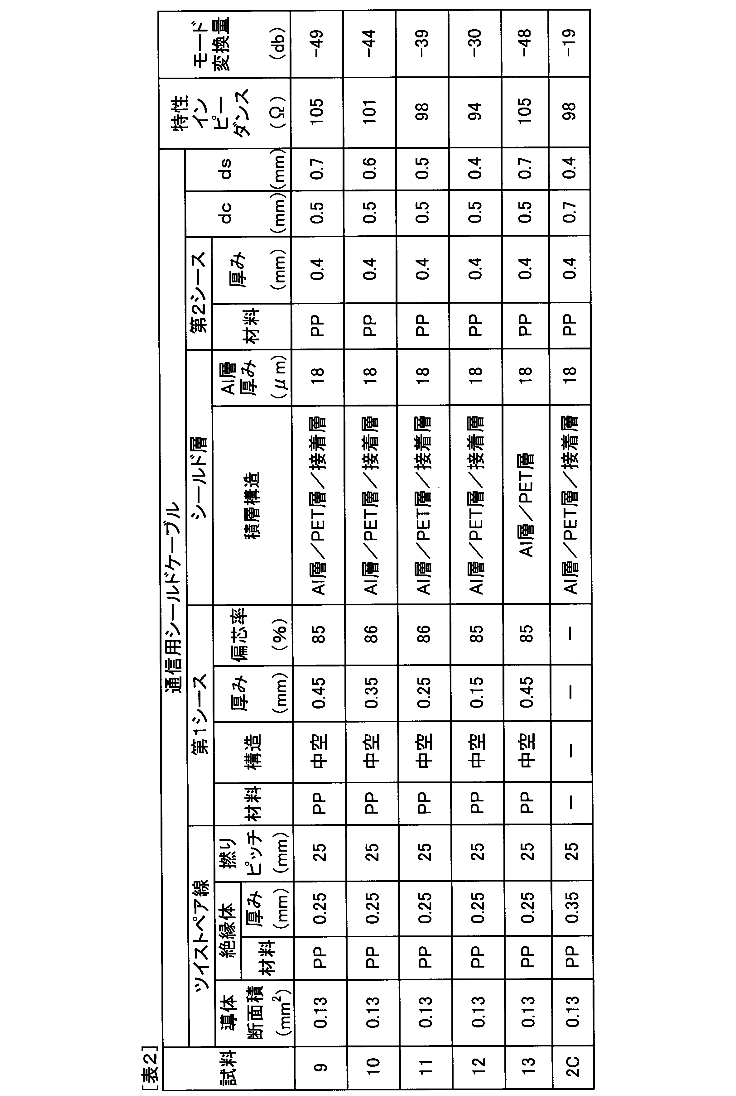
表1および表2によれば、以下のことがわかる。試料1Cおよび試料2Cは、ツイストペア線とシールド層との間に第1シースがない。そのため、試料1Cおよび試料2Cは、モード変換量が極めて大きくなった。これは、ツイストペア線のコア線とシールド層との間に第1シースがないことで、コア線とシールド層との間の物理的な距離を十分に取ることができず、コア線とシールド層との間の電磁結合を弱めることができずにコモンモードインピーダンスが低下したためである。
According to Table 1 and Table 2, the following can be understood. Sample 1C and sample 2C have no first sheath between the twisted pair wire and the shield layer. Therefore, the mode conversion amount of Sample 1C and Sample 2C was extremely large. This is because there is no first sheath between the core wire of the twisted pair wire and the shield layer, so that a sufficient physical distance between the core wire and the shield layer cannot be taken. This is because the common mode impedance was lowered without being able to weaken the electromagnetic coupling between the two.
これに対し、試料1~試料13は、従来に比べ、モード変換量を低減することができた。これは、試料1~試料13では、ツイストペア線とシールド層との間に配置された第1シースにより、コア線とシールド層との間に物理的な距離を取ることが可能となり、コア線とシールド層との間の電磁結合を弱めることができたためである。したがって、試料1~試料13によれば、モード変換の抑制効果により、高速通信に好適な通信用シールドケーブルが得られることがわかる。また、ツイストペア線を用いることで、外来ノイズ(磁界ノイズ)の影響を抑制できるとともに、端子圧着等によるワイヤーハーネスの加工性にも優れる。それ故、試料1~試料13によれば、自動車向けとして好適な通信用シールドケーブルが得られることがわかる。
In contrast, Sample 1 to Sample 13 were able to reduce the amount of mode conversion compared to the conventional case. In Sample 1 to Sample 13, it is possible to provide a physical distance between the core wire and the shield layer by the first sheath disposed between the twisted pair wire and the shield layer. This is because the electromagnetic coupling with the shield layer could be weakened. Therefore, according to samples 1 to 13, it can be seen that a shielded cable for communication suitable for high-speed communication can be obtained due to the effect of suppressing mode conversion. Moreover, by using a twisted pair wire, the influence of external noise (magnetic field noise) can be suppressed, and the workability of the wire harness by terminal crimping is excellent. Therefore, according to samples 1 to 13, it can be seen that a shielded cable for communication suitable for automobiles can be obtained.
また、試料1~13を比較すると、以下のことがわかる。試料1~試料3と試料4とを比較すると、dc≦dsを満たすことにより、モード変換量の低減効果がより大きくなることが確認された。これは、dc≦dsを満たすことにより、コア線の導体とシールド層との間の電磁結合を大幅に小さくすることが可能となるためであると考えられる。また、試料9~試料11と試料12とを比較すると、上記と同様のことがいえる。
Also, comparing Samples 1 to 13, the following can be found. When Samples 1 to 3 and Sample 4 were compared, it was confirmed that the effect of reducing the mode conversion amount was increased by satisfying dc ≦ ds. This is considered to be because the electromagnetic coupling between the conductor of the core wire and the shield layer can be significantly reduced by satisfying dc ≦ ds. Further, when Samples 9 to 11 and Sample 12 are compared, the same can be said.
次に、試料1と試料5および試料6とを比較すると、ツイストペア線と第1シースとの間に空隙を有する中空構造とすることにより、ツイストペア線と第1シースとの間に実質的に空隙がない充実構造とした場合に比べ、特性インピーダンスの低下を抑制しやすくなることが確認された。これは、充実構造では、ツイストペア線の周囲の誘電率が上昇するのに対し、中空構造によれば、空隙によってツイストペア線の周囲の誘電率が上昇するのを抑制することができたためである。また、充実構造では、特性インピーダンスを所望の値に合わせるために、コア線の絶縁体の厚みを厚くする必要があり、ケーブルが太径化しやすいといえる。これに対し、中空構造によれば、必要な特性インピーダンスを確保しつつ、コア線の絶縁体の厚みを薄くできるので、ケーブルの細径化に有利であるといえる。
Next, when the sample 1 is compared with the sample 5 and the sample 6, by forming a hollow structure having a gap between the twisted pair wire and the first sheath, there is substantially no gap between the twisted pair wire and the first sheath. It was confirmed that it was easier to suppress a decrease in characteristic impedance than in the case of a solid structure with no gap. This is because in the solid structure, the dielectric constant around the twisted pair wire increases, whereas in the hollow structure, the increase in the dielectric constant around the twisted pair wire can be suppressed by the air gap. Further, in the full structure, it is necessary to increase the thickness of the insulator of the core wire in order to match the characteristic impedance to a desired value, and it can be said that the cable is likely to have a large diameter. On the other hand, according to the hollow structure, it is possible to reduce the thickness of the cable because the thickness of the insulator of the core wire can be reduced while ensuring the necessary characteristic impedance.
次に、試料1~試料8を比較すると、ツイストペア線の撚りピッチが40mmよりも大きくなると、第1シースの偏芯率が低下する傾向が見られた。これは、ツイストペア線の撚りピッチが大きくなることで、2本のコア線間に第1シースが入り込みやすくなったためである。そのため、ツイストペア線の撚りピッチは、40mm以上とすることが好ましいことが確認された。また、第1シースの偏芯率が80%未満になると、ケーブル加工性やケーブル特性への悪影響が懸念されるため、第1シースの偏芯率は、80%以上とすることが好ましいことが確認された。
Next, when samples 1 to 8 were compared, when the twist pitch of the twisted pair wires was larger than 40 mm, the eccentricity of the first sheath tended to decrease. This is because the twisted wire of the twisted pair wire is increased, so that the first sheath can easily enter between the two core wires. Therefore, it was confirmed that the twist pitch of the twisted pair wire is preferably 40 mm or more. Further, if the eccentricity of the first sheath is less than 80%, there is a concern about adverse effects on cable workability and cable characteristics. Therefore, the eccentricity of the first sheath is preferably 80% or more. confirmed.
また、試料9~13を比較すると、シールド層として、アルミニウム箔層/PET層/接着層の積層構造を有する積層体を用いた場合には、アルミニウム箔層/PET層を有する積層体を用いた場合に比較して、皮剥ぎ性に優れることも確認された。
Further, comparing Samples 9 to 13, when a laminate having a laminated structure of an aluminum foil layer / PET layer / adhesive layer was used as the shield layer, a laminate having an aluminum foil layer / PET layer was used. Compared to the case, it was also confirmed that the peelability was excellent.
以上、本発明の実施例、実験例について詳細に説明したが、本発明は上記実施例、実験例に限定されるものではなく、本発明の趣旨を損なわない範囲内で種々の変更が可能である。
As mentioned above, although the Example of this invention and the experiment example were demonstrated in detail, this invention is not limited to the said Example and experiment example, A various change is possible within the range which does not impair the meaning of this invention. is there.
Claims (10)
- 導体と上記導体を被覆する絶縁体とを有する一対のコア線を備え、上記一対のコア線が撚り合わされているツイストペア線と、
上記ツイストペア線を被覆する第1シースと、
上記第1シースを被覆するシールド層と、
上記シールド層を被覆する第2シースと、
を有する、通信用シールドケーブル。 A pair of core wires having a conductor and an insulator covering the conductor, and the twisted pair wires in which the pair of core wires are twisted together;
A first sheath covering the twisted pair wire;
A shield layer covering the first sheath;
A second sheath covering the shield layer;
A shielded cable for communication. - 上記一対のコア線間における導体間距離dcと、上記コア線の上記導体と上記シールド層との間の最短距離dsとが、dc≦dsを満たす、請求項1に記載の通信用シールドケーブル。 The shielded cable for communication according to claim 1, wherein the inter-conductor distance dc between the pair of core wires and the shortest distance ds between the conductor of the core wires and the shield layer satisfy dc≤ds.
- 上記ツイストペア線と上記第1シースとの間に空隙を有する、請求項1または2に記載の通信用シールドケーブル。 The shielded cable for communication according to claim 1 or 2, wherein a gap is provided between the twisted pair wire and the first sheath.
- 上記ツイストペア線の撚りピッチが、40mm以下である、請求項1~3のいずれか1項に記載の通信用シールドケーブル。 The communication shielded cable according to any one of claims 1 to 3, wherein a twist pitch of the twisted pair wire is 40 mm or less.
- 上記シールド層は、金属箔層と、上記金属箔層の一方面に積層された樹脂層とを有する積層体より構成される、請求項1~4のいずれか1項に記載の通信用シールドケーブル。 The communication shield cable according to any one of claims 1 to 4, wherein the shield layer includes a laminate including a metal foil layer and a resin layer laminated on one surface of the metal foil layer. .
- 上記シールド層は、金属箔層と、上記金属箔層の外側表面に積層された樹脂層と、上記樹脂層の外側表面に積層された接着層とを有する積層体より構成される、請求項1~4のいずれか1項に記載の通信用シールドケーブル。 The said shield layer is comprised from the laminated body which has a metal foil layer, the resin layer laminated | stacked on the outer surface of the said metal foil layer, and the contact bonding layer laminated | stacked on the outer surface of the said resin layer. The shielded cable for communication according to any one of 1 to 4.
- 上記シールド層は、上記第1シースの外周を覆う編組線より構成される、請求項1~4のいずれか1項に記載の通信用シールドケーブル。 The communication shield cable according to any one of claims 1 to 4, wherein the shield layer is formed of a braided wire covering an outer periphery of the first sheath.
- 上記シールド層は、上記第1シースの外周を覆う金属箔および上記金属箔と導通するドレイン線より構成される、請求項1~4のいずれか1項に記載の通信用シールドケーブル。 The communication shield cable according to any one of claims 1 to 4, wherein the shield layer includes a metal foil that covers an outer periphery of the first sheath and a drain wire that is electrically connected to the metal foil.
- 特性インピーダンスが90Ω以上110Ω以下である、請求項1~8のいずれか1項に記載の通信用シールドケーブル。 The shielded cable for communication according to any one of claims 1 to 8, wherein the characteristic impedance is 90Ω to 110Ω.
- 自動車における通信に用いられる、請求項1~9のいずれか1項に記載の通信用シールドケーブル。 The shielded cable for communication according to any one of claims 1 to 9, which is used for communication in an automobile.
Priority Applications (4)
| Application Number | Priority Date | Filing Date | Title |
|---|---|---|---|
| DE112017006006.0T DE112017006006T5 (en) | 2016-11-28 | 2017-10-20 | Shielded communication cable |
| US16/463,641 US10818415B2 (en) | 2016-11-28 | 2017-10-20 | Shielded communication cable |
| CN201780069460.1A CN110088850B (en) | 2016-11-28 | 2017-10-20 | Shielding cable for communication |
| JP2018552471A JP6760392B2 (en) | 2016-11-28 | 2017-10-20 | Shielded cable for communication |
Applications Claiming Priority (2)
| Application Number | Priority Date | Filing Date | Title |
|---|---|---|---|
| JP2016230174 | 2016-11-28 | ||
| JP2016-230174 | 2016-11-28 |
Publications (1)
| Publication Number | Publication Date |
|---|---|
| WO2018096854A1 true WO2018096854A1 (en) | 2018-05-31 |
Family
ID=62195467
Family Applications (1)
| Application Number | Title | Priority Date | Filing Date |
|---|---|---|---|
| PCT/JP2017/038000 WO2018096854A1 (en) | 2016-11-28 | 2017-10-20 | Shielded cable for communication |
Country Status (5)
| Country | Link |
|---|---|
| US (1) | US10818415B2 (en) |
| JP (1) | JP6760392B2 (en) |
| CN (1) | CN110088850B (en) |
| DE (1) | DE112017006006T5 (en) |
| WO (1) | WO2018096854A1 (en) |
Cited By (4)
| Publication number | Priority date | Publication date | Assignee | Title |
|---|---|---|---|---|
| US20190131032A1 (en) * | 2017-10-31 | 2019-05-02 | Yazaki Corporation | Communication electric wire and wire harness |
| KR20200101262A (en) * | 2019-02-19 | 2020-08-27 | 엘에스전선 주식회사 | Ethernet cable |
| JP2020149854A (en) * | 2019-03-13 | 2020-09-17 | 株式会社オートネットワーク技術研究所 | Shield wire for communication |
| US20220028580A1 (en) * | 2020-07-27 | 2022-01-27 | Sumitomo Wiring Systems, Ltd. | End structure and sleeve of shielded cable |
Families Citing this family (4)
| Publication number | Priority date | Publication date | Assignee | Title |
|---|---|---|---|---|
| WO2019208401A1 (en) * | 2018-04-25 | 2019-10-31 | ダイキン工業株式会社 | Stranded wire and method of manufacture therefor |
| CN111933332A (en) * | 2020-07-07 | 2020-11-13 | 中筑科技股份有限公司 | Interference-preventing high-strength cable for central air conditioner |
| WO2023068827A1 (en) * | 2021-10-20 | 2023-04-27 | 엘에스전선 주식회사 | Ethernet cable |
| WO2024064323A1 (en) * | 2022-09-23 | 2024-03-28 | Amphenol Corporation | High speed twin-axial cable |
Citations (3)
| Publication number | Priority date | Publication date | Assignee | Title |
|---|---|---|---|---|
| JP2009181855A (en) * | 2008-01-31 | 2009-08-13 | Ibiden Co Ltd | Cable |
| JP2012109128A (en) * | 2010-11-18 | 2012-06-07 | Nsk Ltd | Shield cable for resolver |
| WO2016052506A1 (en) * | 2014-10-03 | 2016-04-07 | タツタ電線株式会社 | Shielded electric wire |
Family Cites Families (28)
| Publication number | Priority date | Publication date | Assignee | Title |
|---|---|---|---|---|
| JPS6039139A (en) * | 1983-08-12 | 1985-02-28 | Mitsui Mining & Smelting Co Ltd | Softening resistant copper alloy with high conductivity |
| US4777325A (en) * | 1987-06-09 | 1988-10-11 | Amp Incorporated | Low profile cables for twisted pairs |
| US4873393A (en) * | 1988-03-21 | 1989-10-10 | American Telephone And Telegraph Company, At&T Bell Laboratories | Local area network cabling arrangement |
| US5283390A (en) * | 1992-07-07 | 1994-02-01 | W. L. Gore & Associates, Inc. | Twisted pair data bus cable |
| US5606151A (en) * | 1993-03-17 | 1997-02-25 | Belden Wire & Cable Company | Twisted parallel cable |
| US5770820A (en) * | 1995-03-15 | 1998-06-23 | Belden Wire & Cable Co | Plenum cable |
| US6211467B1 (en) * | 1998-08-06 | 2001-04-03 | Prestolite Wire Corporation | Low loss data cable |
| US6153826A (en) * | 1999-05-28 | 2000-11-28 | Prestolite Wire Corporation | Optimizing lan cable performance |
| WO2000074078A1 (en) * | 1999-05-28 | 2000-12-07 | Krone Digital Communications, Inc. | Low delay skew multi-pair cable and method of manufacture |
| GB2366661B (en) * | 1999-06-18 | 2003-07-23 | Belden Wire & Cable Co | High performance data cable |
| GB9930509D0 (en) * | 1999-12-24 | 2000-02-16 | Plastic Insulated Cables Ltd | Communications cable |
| GB2419225B (en) * | 2003-07-28 | 2007-08-01 | Belden Cdt Networking Inc | Skew adjusted data cable |
| JP2006019080A (en) * | 2004-06-30 | 2006-01-19 | Hitachi Cable Ltd | Differential signal transmission cable |
| KR100825408B1 (en) * | 2007-04-13 | 2008-04-29 | 엘에스전선 주식회사 | Communication cable of high capacity |
| JP2011096574A (en) | 2009-10-30 | 2011-05-12 | Hitachi Cable Ltd | Cable for differential signal transmission |
| JP2012038637A (en) | 2010-08-10 | 2012-02-23 | Sumitomo Electric Ind Ltd | Cable |
| JP2012248310A (en) * | 2011-05-25 | 2012-12-13 | Hitachi Cable Ltd | Twisted pair wire using a stranded conductor with humidity resistance and twisted pair cable |
| CN202339747U (en) * | 2011-12-07 | 2012-07-18 | 广西科友通信科技有限公司 | Polyvinyl chloride insulation sleeve shielding flexible wire (RVVP) shielding power supply control line |
| US9196400B2 (en) * | 2011-12-21 | 2015-11-24 | Belden Inc. | Systems and methods for producing cable |
| CN102623092B (en) * | 2012-04-12 | 2013-06-05 | 江苏亨通线缆科技有限公司 | Flat type anti-interference data cable |
| JP5895869B2 (en) | 2013-02-15 | 2016-03-30 | 日立金属株式会社 | Insulated cable and manufacturing method thereof |
| US20140262424A1 (en) * | 2013-03-14 | 2014-09-18 | Delphi Technologies, Inc. | Shielded twisted pair cable |
| CN103514983A (en) * | 2013-10-14 | 2014-01-15 | 扬州新奇特电缆材料有限公司 | Aluminum plastic composite belt and preparing method thereof |
| US9805844B2 (en) * | 2014-06-24 | 2017-10-31 | Commscope Technologies Llc | Twisted pair cable with shielding arrangement |
| CN204155630U (en) * | 2014-08-15 | 2015-02-11 | 安徽天康股份有限公司 | A kind of high-temperature resistant polytetrafluoroethylmelt insulated copper aluminium alloy shielding compensating cable |
| CN204303371U (en) * | 2014-11-14 | 2015-04-29 | 黄石昌达线缆有限公司 | Automobile heat resistant type shielded type cable |
| WO2017132327A1 (en) * | 2016-01-27 | 2017-08-03 | Hitachi Cable America, Inc. | Extended frequency range balanced twisted pair transmission line or communication cable |
| CN205631570U (en) * | 2016-05-16 | 2016-10-12 | 常州义长新材料科技有限公司 | Self -adhesion plastic -aluminum composite insulating foils structure |
-
2017
- 2017-10-20 WO PCT/JP2017/038000 patent/WO2018096854A1/en active Application Filing
- 2017-10-20 CN CN201780069460.1A patent/CN110088850B/en active Active
- 2017-10-20 DE DE112017006006.0T patent/DE112017006006T5/en active Pending
- 2017-10-20 JP JP2018552471A patent/JP6760392B2/en active Active
- 2017-10-20 US US16/463,641 patent/US10818415B2/en active Active
Patent Citations (3)
| Publication number | Priority date | Publication date | Assignee | Title |
|---|---|---|---|---|
| JP2009181855A (en) * | 2008-01-31 | 2009-08-13 | Ibiden Co Ltd | Cable |
| JP2012109128A (en) * | 2010-11-18 | 2012-06-07 | Nsk Ltd | Shield cable for resolver |
| WO2016052506A1 (en) * | 2014-10-03 | 2016-04-07 | タツタ電線株式会社 | Shielded electric wire |
Cited By (11)
| Publication number | Priority date | Publication date | Assignee | Title |
|---|---|---|---|---|
| US20190131032A1 (en) * | 2017-10-31 | 2019-05-02 | Yazaki Corporation | Communication electric wire and wire harness |
| KR20200101262A (en) * | 2019-02-19 | 2020-08-27 | 엘에스전선 주식회사 | Ethernet cable |
| KR102181049B1 (en) | 2019-02-19 | 2020-11-19 | 엘에스전선 주식회사 | Ethernet cable |
| JP2020149854A (en) * | 2019-03-13 | 2020-09-17 | 株式会社オートネットワーク技術研究所 | Shield wire for communication |
| WO2020183925A1 (en) * | 2019-03-13 | 2020-09-17 | 株式会社オートネットワーク技術研究所 | Communication shielding electric wire |
| CN113508441A (en) * | 2019-03-13 | 2021-10-15 | 株式会社自动网络技术研究所 | Shielded wire for communication |
| US20220189660A1 (en) * | 2019-03-13 | 2022-06-16 | Autonetworks Technologies, Ltd. | Shielded communication cable |
| JP7234708B2 (en) | 2019-03-13 | 2023-03-08 | 株式会社オートネットワーク技術研究所 | Shielded wire for communication |
| CN113508441B (en) * | 2019-03-13 | 2023-11-21 | 株式会社自动网络技术研究所 | Shielded wire for communication |
| US20220028580A1 (en) * | 2020-07-27 | 2022-01-27 | Sumitomo Wiring Systems, Ltd. | End structure and sleeve of shielded cable |
| US11742111B2 (en) * | 2020-07-27 | 2023-08-29 | Sumitomo Wiring Systems, Ltd. | End structure and sleeve of shielded cable |
Also Published As
| Publication number | Publication date |
|---|---|
| CN110088850A (en) | 2019-08-02 |
| JPWO2018096854A1 (en) | 2019-10-31 |
| CN110088850B (en) | 2021-01-08 |
| US20200168366A1 (en) | 2020-05-28 |
| US10818415B2 (en) | 2020-10-27 |
| DE112017006006T5 (en) | 2019-08-29 |
| JP6760392B2 (en) | 2020-09-23 |
Similar Documents
| Publication | Publication Date | Title |
|---|---|---|
| WO2018096854A1 (en) | Shielded cable for communication | |
| JP5508614B2 (en) | High-speed differential cable | |
| JP4933344B2 (en) | Shielded twisted pair cable | |
| WO2013069755A1 (en) | High-speed signal transmission cable | |
| US20110247856A1 (en) | Shielded cable | |
| JP5391848B2 (en) | Twisted pair cable and manufacturing method thereof | |
| JP2018181591A (en) | Two-core parallel cable | |
| WO2017168815A1 (en) | Shielded wire for communication | |
| US20190304633A1 (en) | Shielded cable | |
| WO2018117204A1 (en) | Electric cable for communication | |
| US20180268965A1 (en) | Data cable for high speed data transmissions and method of manufacturing the data cable | |
| JP2016045982A (en) | Impedance adjustment method of twist pair electric wire, twist pair electric wire and wire harness | |
| JP5330888B2 (en) | High-speed differential cable | |
| JP2014017131A (en) | Shield cable | |
| WO2014185468A1 (en) | Signal cable and wire harness | |
| JP2007280762A (en) | Non-halogen coaxial cable, and multicore cable using it | |
| JP7339042B2 (en) | Differential transmission cable and wire harness | |
| WO2020183925A1 (en) | Communication shielding electric wire | |
| JP2010073463A (en) | High-speed differential cable | |
| JP5095272B2 (en) | Electromagnetic wire | |
| CN104616790A (en) | Silver-plated aluminum alloy strip armored motor drainage cable | |
| JP2003031046A (en) | Two-core parallel extra-file coaxial cable with longitudinally added deposited tape | |
| JP2023067141A (en) | Electric wire for communication | |
| JP2023009377A (en) | Signal transmission cable | |
| CN117275808A (en) | Twisted pair shielded cable and wire harness |
Legal Events
| Date | Code | Title | Description |
|---|---|---|---|
| 121 | Ep: the epo has been informed by wipo that ep was designated in this application |
Ref document number: 17873188 Country of ref document: EP Kind code of ref document: A1 |
|
| ENP | Entry into the national phase |
Ref document number: 2018552471 Country of ref document: JP Kind code of ref document: A |
|
| 122 | Ep: pct application non-entry in european phase |
Ref document number: 17873188 Country of ref document: EP Kind code of ref document: A1 |