WO2018096660A1 - Automatic filling device - Google Patents
Automatic filling device Download PDFInfo
- Publication number
- WO2018096660A1 WO2018096660A1 PCT/JP2016/085023 JP2016085023W WO2018096660A1 WO 2018096660 A1 WO2018096660 A1 WO 2018096660A1 JP 2016085023 W JP2016085023 W JP 2016085023W WO 2018096660 A1 WO2018096660 A1 WO 2018096660A1
- Authority
- WO
- WIPO (PCT)
- Prior art keywords
- insert
- dispenser
- edge
- injection hole
- automatic filling
- Prior art date
Links
- 238000002347 injection Methods 0.000 claims abstract description 48
- 239000007924 injection Substances 0.000 claims abstract description 48
- 239000000853 adhesive Substances 0.000 claims abstract description 25
- 230000001070 adhesive effect Effects 0.000 claims abstract description 25
- 239000000945 filler Substances 0.000 claims description 52
- 238000005259 measurement Methods 0.000 claims description 45
- 239000007788 liquid Substances 0.000 claims description 36
- 238000003825 pressing Methods 0.000 claims description 25
- 238000006073 displacement reaction Methods 0.000 claims description 20
- 238000002156 mixing Methods 0.000 claims description 4
- 230000003068 static effect Effects 0.000 claims description 4
- 238000003756 stirring Methods 0.000 claims description 3
- 238000013459 approach Methods 0.000 claims 1
- 239000000203 mixture Substances 0.000 claims 1
- 239000003795 chemical substances by application Substances 0.000 description 31
- 238000000034 method Methods 0.000 description 24
- 238000007781 pre-processing Methods 0.000 description 16
- 238000012545 processing Methods 0.000 description 16
- 230000004044 response Effects 0.000 description 9
- 238000010586 diagram Methods 0.000 description 8
- 239000000463 material Substances 0.000 description 7
- 230000006870 function Effects 0.000 description 6
- 238000007599 discharging Methods 0.000 description 4
- 229920006332 epoxy adhesive Polymers 0.000 description 4
- 230000000694 effects Effects 0.000 description 3
- 229910052751 metal Inorganic materials 0.000 description 3
- 239000002184 metal Substances 0.000 description 3
- 102100040287 GTP cyclohydrolase 1 feedback regulatory protein Human genes 0.000 description 2
- 101710185324 GTP cyclohydrolase 1 feedback regulatory protein Proteins 0.000 description 2
- 230000001174 ascending effect Effects 0.000 description 2
- 239000004918 carbon fiber reinforced polymer Substances 0.000 description 2
- 238000001514 detection method Methods 0.000 description 2
- 238000005553 drilling Methods 0.000 description 2
- 239000004848 polyfunctional curative Substances 0.000 description 2
- 229910052782 aluminium Inorganic materials 0.000 description 1
- XAGFODPZIPBFFR-UHFFFAOYSA-N aluminium Chemical compound [Al] XAGFODPZIPBFFR-UHFFFAOYSA-N 0.000 description 1
- 239000002131 composite material Substances 0.000 description 1
- 238000011960 computer-aided design Methods 0.000 description 1
- 239000011152 fibreglass Substances 0.000 description 1
- 230000003287 optical effect Effects 0.000 description 1
- 238000003908 quality control method Methods 0.000 description 1
- 239000013589 supplement Substances 0.000 description 1
Images


Classifications
-
- B—PERFORMING OPERATIONS; TRANSPORTING
- B29—WORKING OF PLASTICS; WORKING OF SUBSTANCES IN A PLASTIC STATE IN GENERAL
- B29C—SHAPING OR JOINING OF PLASTICS; SHAPING OF MATERIAL IN A PLASTIC STATE, NOT OTHERWISE PROVIDED FOR; AFTER-TREATMENT OF THE SHAPED PRODUCTS, e.g. REPAIRING
- B29C70/00—Shaping composites, i.e. plastics material comprising reinforcements, fillers or preformed parts, e.g. inserts
- B29C70/68—Shaping composites, i.e. plastics material comprising reinforcements, fillers or preformed parts, e.g. inserts by incorporating or moulding on preformed parts, e.g. inserts or layers, e.g. foam blocks
- B29C70/86—Incorporated in coherent impregnated reinforcing layers, e.g. by winding
-
- B—PERFORMING OPERATIONS; TRANSPORTING
- B29—WORKING OF PLASTICS; WORKING OF SUBSTANCES IN A PLASTIC STATE IN GENERAL
- B29C—SHAPING OR JOINING OF PLASTICS; SHAPING OF MATERIAL IN A PLASTIC STATE, NOT OTHERWISE PROVIDED FOR; AFTER-TREATMENT OF THE SHAPED PRODUCTS, e.g. REPAIRING
- B29C65/00—Joining or sealing of preformed parts, e.g. welding of plastics materials; Apparatus therefor
- B29C65/48—Joining or sealing of preformed parts, e.g. welding of plastics materials; Apparatus therefor using adhesives, i.e. using supplementary joining material; solvent bonding
- B29C65/52—Joining or sealing of preformed parts, e.g. welding of plastics materials; Apparatus therefor using adhesives, i.e. using supplementary joining material; solvent bonding characterised by the way of applying the adhesive
- B29C65/54—Joining or sealing of preformed parts, e.g. welding of plastics materials; Apparatus therefor using adhesives, i.e. using supplementary joining material; solvent bonding characterised by the way of applying the adhesive between pre-assembled parts
- B29C65/542—Joining or sealing of preformed parts, e.g. welding of plastics materials; Apparatus therefor using adhesives, i.e. using supplementary joining material; solvent bonding characterised by the way of applying the adhesive between pre-assembled parts by injection
-
- B—PERFORMING OPERATIONS; TRANSPORTING
- B05—SPRAYING OR ATOMISING IN GENERAL; APPLYING FLUENT MATERIALS TO SURFACES, IN GENERAL
- B05C—APPARATUS FOR APPLYING FLUENT MATERIALS TO SURFACES, IN GENERAL
- B05C5/00—Apparatus in which liquid or other fluent material is projected, poured or allowed to flow on to the surface of the work
- B05C5/02—Apparatus in which liquid or other fluent material is projected, poured or allowed to flow on to the surface of the work the liquid or other fluent material being discharged through an outlet orifice by pressure, e.g. from an outlet device in contact or almost in contact, with the work
-
- B—PERFORMING OPERATIONS; TRANSPORTING
- B32—LAYERED PRODUCTS
- B32B—LAYERED PRODUCTS, i.e. PRODUCTS BUILT-UP OF STRATA OF FLAT OR NON-FLAT, e.g. CELLULAR OR HONEYCOMB, FORM
- B32B15/00—Layered products comprising a layer of metal
- B32B15/04—Layered products comprising a layer of metal comprising metal as the main or only constituent of a layer, which is next to another layer of the same or of a different material
-
- B—PERFORMING OPERATIONS; TRANSPORTING
- B32—LAYERED PRODUCTS
- B32B—LAYERED PRODUCTS, i.e. PRODUCTS BUILT-UP OF STRATA OF FLAT OR NON-FLAT, e.g. CELLULAR OR HONEYCOMB, FORM
- B32B15/00—Layered products comprising a layer of metal
- B32B15/20—Layered products comprising a layer of metal comprising aluminium or copper
-
- B—PERFORMING OPERATIONS; TRANSPORTING
- B32—LAYERED PRODUCTS
- B32B—LAYERED PRODUCTS, i.e. PRODUCTS BUILT-UP OF STRATA OF FLAT OR NON-FLAT, e.g. CELLULAR OR HONEYCOMB, FORM
- B32B27/00—Layered products comprising a layer of synthetic resin
- B32B27/06—Layered products comprising a layer of synthetic resin as the main or only constituent of a layer, which is next to another layer of the same or of a different material
-
- B—PERFORMING OPERATIONS; TRANSPORTING
- B32—LAYERED PRODUCTS
- B32B—LAYERED PRODUCTS, i.e. PRODUCTS BUILT-UP OF STRATA OF FLAT OR NON-FLAT, e.g. CELLULAR OR HONEYCOMB, FORM
- B32B3/00—Layered products comprising a layer with external or internal discontinuities or unevennesses, or a layer of non-planar shape; Layered products comprising a layer having particular features of form
- B32B3/02—Layered products comprising a layer with external or internal discontinuities or unevennesses, or a layer of non-planar shape; Layered products comprising a layer having particular features of form characterised by features of form at particular places, e.g. in edge regions
- B32B3/08—Layered products comprising a layer with external or internal discontinuities or unevennesses, or a layer of non-planar shape; Layered products comprising a layer having particular features of form characterised by features of form at particular places, e.g. in edge regions characterised by added members at particular parts
-
- B—PERFORMING OPERATIONS; TRANSPORTING
- B32—LAYERED PRODUCTS
- B32B—LAYERED PRODUCTS, i.e. PRODUCTS BUILT-UP OF STRATA OF FLAT OR NON-FLAT, e.g. CELLULAR OR HONEYCOMB, FORM
- B32B3/00—Layered products comprising a layer with external or internal discontinuities or unevennesses, or a layer of non-planar shape; Layered products comprising a layer having particular features of form
- B32B3/10—Layered products comprising a layer with external or internal discontinuities or unevennesses, or a layer of non-planar shape; Layered products comprising a layer having particular features of form characterised by a discontinuous layer, i.e. formed of separate pieces of material
- B32B3/12—Layered products comprising a layer with external or internal discontinuities or unevennesses, or a layer of non-planar shape; Layered products comprising a layer having particular features of form characterised by a discontinuous layer, i.e. formed of separate pieces of material characterised by a layer of regularly- arranged cells, e.g. a honeycomb structure
-
- B—PERFORMING OPERATIONS; TRANSPORTING
- B32—LAYERED PRODUCTS
- B32B—LAYERED PRODUCTS, i.e. PRODUCTS BUILT-UP OF STRATA OF FLAT OR NON-FLAT, e.g. CELLULAR OR HONEYCOMB, FORM
- B32B3/00—Layered products comprising a layer with external or internal discontinuities or unevennesses, or a layer of non-planar shape; Layered products comprising a layer having particular features of form
- B32B3/26—Layered products comprising a layer with external or internal discontinuities or unevennesses, or a layer of non-planar shape; Layered products comprising a layer having particular features of form characterised by a particular shape of the outline of the cross-section of a continuous layer; characterised by a layer with cavities or internal voids ; characterised by an apertured layer
- B32B3/266—Layered products comprising a layer with external or internal discontinuities or unevennesses, or a layer of non-planar shape; Layered products comprising a layer having particular features of form characterised by a particular shape of the outline of the cross-section of a continuous layer; characterised by a layer with cavities or internal voids ; characterised by an apertured layer characterised by an apertured layer, the apertures going through the whole thickness of the layer, e.g. expanded metal, perforated layer, slit layer regular cells B32B3/12
-
- B—PERFORMING OPERATIONS; TRANSPORTING
- B32—LAYERED PRODUCTS
- B32B—LAYERED PRODUCTS, i.e. PRODUCTS BUILT-UP OF STRATA OF FLAT OR NON-FLAT, e.g. CELLULAR OR HONEYCOMB, FORM
- B32B3/00—Layered products comprising a layer with external or internal discontinuities or unevennesses, or a layer of non-planar shape; Layered products comprising a layer having particular features of form
- B32B3/26—Layered products comprising a layer with external or internal discontinuities or unevennesses, or a layer of non-planar shape; Layered products comprising a layer having particular features of form characterised by a particular shape of the outline of the cross-section of a continuous layer; characterised by a layer with cavities or internal voids ; characterised by an apertured layer
- B32B3/30—Layered products comprising a layer with external or internal discontinuities or unevennesses, or a layer of non-planar shape; Layered products comprising a layer having particular features of form characterised by a particular shape of the outline of the cross-section of a continuous layer; characterised by a layer with cavities or internal voids ; characterised by an apertured layer characterised by a layer formed with recesses or projections, e.g. hollows, grooves, protuberances, ribs
-
- B—PERFORMING OPERATIONS; TRANSPORTING
- B32—LAYERED PRODUCTS
- B32B—LAYERED PRODUCTS, i.e. PRODUCTS BUILT-UP OF STRATA OF FLAT OR NON-FLAT, e.g. CELLULAR OR HONEYCOMB, FORM
- B32B7/00—Layered products characterised by the relation between layers; Layered products characterised by the relative orientation of features between layers, or by the relative values of a measurable parameter between layers, i.e. products comprising layers having different physical, chemical or physicochemical properties; Layered products characterised by the interconnection of layers
- B32B7/04—Interconnection of layers
- B32B7/12—Interconnection of layers using interposed adhesives or interposed materials with bonding properties
-
- C—CHEMISTRY; METALLURGY
- C09—DYES; PAINTS; POLISHES; NATURAL RESINS; ADHESIVES; COMPOSITIONS NOT OTHERWISE PROVIDED FOR; APPLICATIONS OF MATERIALS NOT OTHERWISE PROVIDED FOR
- C09J—ADHESIVES; NON-MECHANICAL ASPECTS OF ADHESIVE PROCESSES IN GENERAL; ADHESIVE PROCESSES NOT PROVIDED FOR ELSEWHERE; USE OF MATERIALS AS ADHESIVES
- C09J5/00—Adhesive processes in general; Adhesive processes not provided for elsewhere, e.g. relating to primers
-
- F—MECHANICAL ENGINEERING; LIGHTING; HEATING; WEAPONS; BLASTING
- F16—ENGINEERING ELEMENTS AND UNITS; GENERAL MEASURES FOR PRODUCING AND MAINTAINING EFFECTIVE FUNCTIONING OF MACHINES OR INSTALLATIONS; THERMAL INSULATION IN GENERAL
- F16B—DEVICES FOR FASTENING OR SECURING CONSTRUCTIONAL ELEMENTS OR MACHINE PARTS TOGETHER, e.g. NAILS, BOLTS, CIRCLIPS, CLAMPS, CLIPS OR WEDGES; JOINTS OR JOINTING
- F16B5/00—Joining sheets or plates, e.g. panels, to one another or to strips or bars parallel to them
-
- B—PERFORMING OPERATIONS; TRANSPORTING
- B29—WORKING OF PLASTICS; WORKING OF SUBSTANCES IN A PLASTIC STATE IN GENERAL
- B29C—SHAPING OR JOINING OF PLASTICS; SHAPING OF MATERIAL IN A PLASTIC STATE, NOT OTHERWISE PROVIDED FOR; AFTER-TREATMENT OF THE SHAPED PRODUCTS, e.g. REPAIRING
- B29C37/00—Component parts, details, accessories or auxiliary operations, not covered by group B29C33/00 or B29C35/00
- B29C37/0078—Measures or configurations for obtaining anchoring effects in the contact areas between layers
- B29C37/0082—Mechanical anchoring
-
- B—PERFORMING OPERATIONS; TRANSPORTING
- B32—LAYERED PRODUCTS
- B32B—LAYERED PRODUCTS, i.e. PRODUCTS BUILT-UP OF STRATA OF FLAT OR NON-FLAT, e.g. CELLULAR OR HONEYCOMB, FORM
- B32B2250/00—Layers arrangement
- B32B2250/40—Symmetrical or sandwich layers, e.g. ABA, ABCBA, ABCCBA
-
- B—PERFORMING OPERATIONS; TRANSPORTING
- B32—LAYERED PRODUCTS
- B32B—LAYERED PRODUCTS, i.e. PRODUCTS BUILT-UP OF STRATA OF FLAT OR NON-FLAT, e.g. CELLULAR OR HONEYCOMB, FORM
- B32B2262/00—Composition or structural features of fibres which form a fibrous or filamentary layer or are present as additives
- B32B2262/10—Inorganic fibres
- B32B2262/106—Carbon fibres, e.g. graphite fibres
-
- B—PERFORMING OPERATIONS; TRANSPORTING
- B32—LAYERED PRODUCTS
- B32B—LAYERED PRODUCTS, i.e. PRODUCTS BUILT-UP OF STRATA OF FLAT OR NON-FLAT, e.g. CELLULAR OR HONEYCOMB, FORM
- B32B2307/00—Properties of the layers or laminate
- B32B2307/70—Other properties
- B32B2307/732—Dimensional properties
Definitions
- the present invention relates to a technique for automatically filling a filler.
- a honeycomb sandwich panel is a structure in which a skin material is bonded to both sides of a honeycomb core with a sheet adhesive.
- An insert is embedded in the honeycomb sandwich panel.
- the insert is a metal part that serves as an interface for connecting a member or device to the honeycomb sandwich panel, and has a hole into which an adhesive is injected.
- An adhesive is an example of a filler. After the insert is embedded in the honeycomb sandwich panel, the adhesive is injected from the hole in the insert and filled between the insert and the honeycomb core. When the adhesive is cured, the insert is fixed to the honeycomb sandwich panel.
- Patent Document 1 discloses an insert filling method.
- the two-component mixed epoxy adhesive is an adhesive in which a high-viscosity main agent and a low-viscosity curing agent are mixed. The amount of distribution between the main agent and the curing agent is determined, and after the respective masses are measured, the main agent and the curing agent are mixed.
- An object of the present invention is to enable automatic filling of a filler.
- the automatic filling device of the present invention is A work stage on which a panel with an embedded hole in which the insert is embedded is placed; A dispenser having a discharge port through which a filler injected from an injection hole provided in the insert is discharged; An air cylinder that presses an edge of the discharge port of the dispenser against an edge of the injection hole of the insert in a state where the panel is placed on the work stage and the insert is embedded in the embedded hole of the panel; Is provided.
- FIG. 3 is a side view of the automatic filling device 100 according to the first embodiment.
- FIG. 2 is a plan view of automatic filling apparatus 100 in the first embodiment.
- FIG. 3 is a structural diagram of an insert 310 in the first embodiment.
- FIG. 3 is a structural diagram of panel 300 in the first embodiment.
- FIG. 3 is a structural diagram of panel 300 in the first embodiment.
- FIG. 3 is a front view of the drive head 200 in the first embodiment.
- FIG. 3 is a side view of the drive head 200 in the first embodiment.
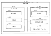
- FIG. 3 is a configuration diagram of a control device according to the first embodiment.
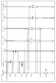
- FIG. 3 is a sequence diagram of the automatic filling method in the first embodiment.
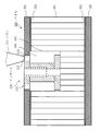
- FIG. 3 is a side cross-sectional view of panel 300 in the first embodiment.
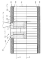
- FIG. 3 is a side cross-sectional view of panel 300 in the first embodiment.
- FIG. 3 is a side cross-sectional view of panel 300 in the first embodiment.
- FIG. 5 shows a filling pattern in the first embodiment.
- FIG. 5 shows a filling pattern in the first embodiment.
- FIG. 5 shows a filling pattern in the first embodiment.
- FIG. 4 is a configuration diagram of a drive head 200 in a second embodiment. The hardware block diagram of the control apparatus 130 in embodiment.
- Embodiment 1 An embodiment in which an adhesive is automatically filled in the gap between the honeycomb sandwich panel and the insert embedded in the honeycomb sandwich panel will be described with reference to FIGS.
- FIG. 1 is a side view and FIG. 2 is a plan view.
- the X axis indicates the width direction
- the Y axis indicates the depth direction
- the Z axis indicates the height direction.
- the X-axis indicates the front-rear direction
- the Y-axis indicates the left-right direction
- the Z-axis indicates the up-down direction.
- O S indicates the origin of the work stage 110
- O P indicates the origin of the panel 300.
- the automatic filling apparatus 100 includes a work stage 110, a moving stage 120, a control device 130, and a drive head 200.
- the work stage 110 is a table on which the panel 300 is placed.
- the moving stage 120 is a frame to which the driving head 200 is attached.
- the moving stage 120 moves electrically in the front-rear direction. Further, the portion to which the drive head 200 is attached moves electrically in the left-right direction.
- the panel 300 is a plate provided with an embedding hole in which the insert 310 is embedded (see FIG. 2).
- the panel 300 has a small size of about 0.4 m ⁇ 0.6 m, and a large size of about 3 m ⁇ 5 m. Further, the number of embedded holes provided in the panel 300 is about 50 to 3000.
- the embedding hole is a depression.
- the embedded hole is provided by drilling using a drilling machine or the like. m means meter.
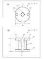
- the structure of the insert 310 will be described based on FIG. FIG. 3A is a plan view, and FIG. 3B is a side view.
- the insert 310 is a component for connecting an object to the panel 300.
- the insert 310 is a metal part.
- the connected object is any member or device.
- the insert 310 includes an upper flange 311, a lower flange 312, and a flange shaft 313.
- the upper flange 311 is a flange disposed on the upper side.
- the upper flange 311 has a disk shape.
- the upper flange 311 is provided with a screw hole 316 at the center and two holes with the screw hole 316 interposed therebetween. The two holes are positioned substantially symmetrically with the screw hole 316 interposed therebetween.
- One hole is referred to as an injection hole 314 and the other hole is referred to as a measurement hole 315.
- the injection hole 314 and the measurement hole 315 pass through the upper flange 311.
- the lower flange 312 is a flange disposed on the lower side.
- the lower flange 312 has a disk shape.
- a shaft hole 317 is provided at the center of the lower flange 312.
- the lower flange 312 does not have a hole corresponding to the injection hole 314 or the measurement hole 315.
- the flange shaft 313 is a shaft that connects the upper flange 311 and the lower flange 312.
- the flange shaft 313 has a cylindrical shape.
- the flange shaft 313 is provided with a screw hole 316 formed partway from the upper flange 311 and a shaft hole 317 that is connected to the screw hole 316 and penetrates to the lower flange 312.
- the specific size of the insert 310 is as follows.
- the diameter D M of the upper flange 311 and lower flange 312 are 10cm order of 1 cm. cm means centimeter.
- the height H of the insert 310 is about 1 cm to 5 cm. Note that the height H of the insert 310 is approximately the same as the depth of the embedded hole provided in the panel 300.
- the shape and size of the insert 310 shown in the embodiment is an example, and the shape and size of the insert 310 may be different from the shape and size shown in the embodiment.
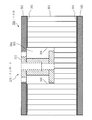
- FIGS. 4 and 5 are side sectional views.
- the panel 300 is a honeycomb sandwich panel used for structures such as artificial satellites.
- the panel 300 includes a honeycomb core 301 and two skin materials 302, and the honeycomb core 301 is sandwiched between the skin materials 302.
- the honeycomb core 301 is composed of a plurality of connected polygonal columns (specifically hexagonal columns). Note that each of the plurality of polygonal columns has a cylindrical shape.
- the skin material 302 is bonded to the upper and lower portions of the honeycomb core 301 by the adhesive sheet 303.
- a specific skin material 302 is aluminum or CFRP (Carbon Fiber Reinforced Plastic).
- the adhesive sheet 303 is a sheet-like adhesive.
- each thickness T is about 1 cm to 5 cm.
- the depth D P of the embedding hole 304 is shallower than the thickness T of the panel 300.
- the depth D P of the embedding hole 304 is about half the thickness T of the panel 300.
- the surface of the upper flange 311 of the insert 310 and the surface of the upper skin material 302 have the same height.
- a gap 305 between the insert 310 and the honeycomb core 301 is filled with a filler.
- the gap 305 between the insert 310 and the honeycomb core 301 means a gap between the insert 310 embedded in the embedding hole 304 and the wall 306 adjacent to the insert 310 among the walls forming the honeycomb core 301.
- an adhesive that fixes the insert 310 to the honeycomb core 301 is filled as a filler.
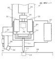
- FIG. 6 is a front view
- FIG. 7 is a side view.
- portions related to the camera 250 and the laser displacement meter 260 are also illustrated, but in FIG. 7, portions related to the camera 250 and the laser displacement meter 260 are not shown.
- the driving head 200 is a device that fills a gap 305 between the insert 310 and the honeycomb core 301 with a filler.
- the driving head 200 includes a dispenser 210, a first tank 221, a second tank 222, an air cylinder 230, a load cell 240, a camera 250, and a laser displacement meter 260. Furthermore, the drive head 200 includes a moving block 201, a linear guide 202, and a base plate 203. Further, the drive head 200 includes an adjustment guide 261 and a base plate 262.
- the moving block 201 is attached to the rail 121 of the moving stage 120, and moves electrically up and down along the rail 121.
- the linear guide 202 is attached to the moving block 201 and moves up and down together with the moving block 201 when the moving block 201 moves up and down. Moreover, the linear guide 202 moves electrically up and down.
- the base plate 203 is attached to the linear guide 202, and moves up and down together with the linear guide 202 when the linear guide 202 moves up and down.
- the dispenser 210 is a device that discharges a filler.
- the dispenser 210 includes a nozzle 211.
- the nozzle 211 has a discharge port 212 through which a filler is discharged at the tip.
- the nozzle 211 is a static mixer that stirs and mixes a plurality of liquids.
- the 1st tank 221 is a container in which the 1st liquid which constitutes a filler is stored.
- the first liquid is supplied from the first tank 221 to the dispenser 210.
- the 2nd tank 222 is a container in which the 2nd liquid which constitutes a filler is stored.
- the second liquid is supplied from the second tank 222 to the dispenser 210.
- the filler is a mixed liquid in which the first liquid and the second liquid are mixed.
- the filler is a two-component mixed epoxy adhesive
- the first liquid is a high-viscosity main agent
- the second liquid is a low-viscosity curing agent.
- the two-component mixed epoxy adhesive is an adhesive in which a high-viscosity main agent and a low-viscosity curing agent are mixed.
- a filler having a medium viscosity or a high viscosity is selected so that the filler does not flow out of the minute hole.
- the air cylinder 230 is a device that moves the nozzle 211 of the dispenser 210 up and down by moving the base plate 203 up and down.
- the air cylinder 230 includes a first pipe 231, a second pipe 232, a regulator 233, and a piston 234.
- the regulator 233 is a device that moves the piston 234 up and down by air pressure by adjusting the air flowing through the first pipe 231 and the air flowing through the second pipe 232.
- the regulator 233 is an electropneumatic regulator.
- the load cell 240 is a sensor that measures the pressing force.
- the pressing force is a force by which the edge of the discharge port 212 of the nozzle 211 is pressed against the edge of the injection hole 314 of the insert 310.
- the load cell 240 measures the force by which the air cylinder 230 pushes down the base plate 203 as a pressing force.
- the camera 250 is a device that photographs the insert 310 located below the nozzle 211 of the dispenser 210.
- the adjustment guide 261 is attached to the moving block 201 and moves up and down together with the moving block 201 when the moving block 201 moves up and down. Further, the adjustment guide 261 moves electrically up, down, left and right.
- the base plate 262 is attached to the adjustment guide 261 and moves together with the adjustment guide 261 when the adjustment guide 261 moves.
- the laser displacement meter 260 is a device that emits laser light toward the lower side of the nozzle 211 of the dispenser 210 and measures the distance to the reflection point.
- the reflection point is a point where the laser beam is reflected.
- the laser displacement meter 260 emits a laser beam toward the measurement hole 315 of the insert 310 located below the nozzle 211, and reaches the liquid level of the filler injected from the injection hole 314 of the insert 310. Measure distance.
- the control device 130 is a computer that controls the moving stage 120 and the driving head 200.
- the control device 130 includes hardware such as a processor 901, a memory 902, an auxiliary storage device 903, and an input / output interface 904. These hardwares are connected to each other via signal lines.
- the processor 901 is an IC (Integrated Circuit) that performs arithmetic processing, and controls other hardware. Specifically, the processor 901 is a CPU (Central Processing Unit).
- the memory 902 is a volatile storage device.
- the memory 902 is also called main memory or main memory.
- the memory 902 is a RAM (Random Access Memory).
- the auxiliary storage device 903 is a nonvolatile storage device. Specifically, the auxiliary storage device 903 is a ROM, HDD, or flash memory. ROM is an abbreviation for Read Only Memory, and HDD is an abbreviation for Hard Disk Drive.
- the input / output interface 904 is a port to which a cable connected to the moving stage 120 and a cable connected to the driving head 200 are connected.
- the control device 130 includes functional elements such as a preprocessing unit 131, a control unit 132, and a recording unit 133.
- the functional element is an element that constitutes a function of the control device 130.
- Functional elements are realized by software. Each functional element will be described later.
- the auxiliary storage device 903 stores a program that realizes functional elements.
- a program that implements functional elements is loaded into the memory 902 and executed by the processor 901.
- the auxiliary storage device 903 stores an OS (Operating System). At least a part of the OS is loaded into the memory 902 and executed by the processor 901. That is, the processor 901 executes a program that realizes functional elements while executing the OS.
- Data obtained by executing a program that implements functional elements is stored in a storage device such as the memory 902, the auxiliary storage device 903, a register in the processor 901, or a cache memory in the processor 901.
- the memory 902 functions as a storage unit 139 that stores data.
- another storage device may function as the storage unit 139 instead of the memory 902 or together with the memory 902.
- the control device 130 may include a plurality of processors that replace the processor 901.
- the plurality of processors share the execution of programs that implement functional elements.
- the program for realizing the functional elements can be stored in a computer-readable manner in a nonvolatile storage medium such as a magnetic disk, an optical disk, or a flash memory.
- a non-volatile storage medium is a tangible medium that is not temporary.
- the operation of the automatic filling apparatus 100 corresponds to an automatic filling method.
- the operation of the control device 130 corresponds to a filling control method.
- the procedure of the filling control method corresponds to the procedure of the filling control program. Processes executed by the preprocessing unit 131, the control unit 132, and the recording unit 133 are referred to as preprocessing, control processing, and recording processing, respectively.
- the pre-processing of the automatic filling method is a process of correcting position information indicating the coordinate value of the discharge port 212 of the nozzle 211.
- the position information is stored in the control device 130 in advance.
- the origin of coordinates in the initial position information is the origin O S of the work stage 110 (see FIG. 2).
- Preprocessing of the automatic filling method is performed in a state where the panel 300 is placed on the work stage 110 and the insert 310 is embedded in the embedding hole 304 of the panel 300.
- the insert 310 is embedded in the embedding hole 304 in a predetermined direction. Specifically, the insert 310 is embedded in the embedded hole 304 so that the injection hole 314 and the measurement hole 315 are aligned in the Y-axis direction.
- the orientation of the insert 310 needs to be unified to some extent. That is, it is necessary to embed the insert 310 in the embedding hole 304 so that the angle formed by the line connecting the injection hole 314 and the measurement hole 315 with respect to the Y axis becomes small. Specifically, the angle formed by the line connecting the injection hole 314 and the measurement hole 315 with respect to the Y axis needs to be within a range of minus 10 degrees to plus 10 degrees.
- the automatic filling apparatus 100 operates as follows.
- the storage unit 139 stores insert coordinate data in advance.
- the insert coordinate data includes the coordinate value of each insert 310.
- the origin of coordinates in the insert coordinate data the origin O P of the panel 300.
- the insert coordinate data is CAD data.
- CAD is an abbreviation for Computer Aided Design.
- the preprocessing unit 131 selects two coordinate values of the reference insert from the insert coordinate data.
- the reference insert is a reference insert 310.
- the reference insert is relatively far insert 310 from the origin O P relatively close insert 310 and the origin O P.
- the preprocessing unit 131 calculates a movement amount based on the coordinate value of the reference insert.
- the preprocessing unit 131 outputs a movement instruction to the movement stage 120 and the movement block 201 based on the calculated movement amount. In response to the movement instruction, the movement stage 120 and the movement block 201 move the nozzle 211 above the reference insert.
- the preprocessing unit 131 outputs a shooting instruction to the camera 250. In response to the shooting instruction, the camera 250 captures the reference insert to obtain an image. Then, the camera 250 outputs the obtained image to the preprocessing unit 131.
- the preprocessing unit 131 receives the image, and calculates the positional deviation amount and the angular deviation amount of the reference insert in the image.
- the positional deviation amount of the reference insert is the magnitude of deviation between the coordinate value of the reference insert in the insert coordinate data and the coordinate value of the reference insert in the image.
- the angle deviation amount of the reference insert is a line obtained by connecting the coordinate values of the two reference inserts of the two reference inserts in the insert coordinate data to the line obtained by connecting the coordinate values of the two reference inserts of the two reference inserts in the image. It is the angle formed with respect to it.
- the preprocessing unit 131 converts the coordinate value of the reference insert in the insert coordinate data into a coordinate value when the coordinate axis in the insert coordinate data is rotated by the amount of angular deviation. Thereafter, the preprocessing unit 131 adds the amount of displacement to the coordinate value of the reference insert in the insert coordinate data.
- the automatic filling method is a method of filling the gap 305 between the insert 310 and the honeycomb core 301 with a filler.
- the automatic filling method is performed after the above pretreatment.
- the processing from step S101 to step S107 is executed for each insert 310.
- Step S ⁇ b> 101 is a step of moving the nozzle 211 above the insert 310.
- Step S101 will be described below.
- the control unit 132 selects the coordinate value of the insert 310 from the insert coordinate data.
- the control unit 132 calculates a movement amount based on the position information and the coordinate value of the insert 310.
- the control unit 132 outputs a movement instruction to the movement stage 120 based on the calculated movement amount.
- the control unit 132 updates the position information based on the calculated movement amount.
- the moving stage 120 moves the nozzle 211 above the insert 310.
- the air cylinder 230 pulls up the dispenser 210 via the base plate 203 with a force that opposes the weight of the parts including the dispenser 210. Thereby, the parts including the dispenser 210 do not descend due to their own weight.
- the components including the dispenser 210 are the dispenser 210, the base plate 203, the first tank 221, the second tank 222, the base plate 203, and the linear guide 202.
- Step S102 is a step of measuring the deviation amount of the injection hole 314 in the insert 310 and the deviation amount of the measurement hole 315 in the insert 310.
- the shift amount of the injection hole 314 is the amount of shift between the reference position for the injection hole 314 and the position of the injection hole 314.
- the amount of deviation of the measurement hole 315 is the magnitude of deviation of the XY coordinates between the reference position for the measurement hole 315 and the position of the measurement hole 315.
- Step S102 will be described below.
- the control unit 132 outputs a shooting instruction to the camera 250.
- the camera 250 receives the shooting instruction and takes an image of the insert 310 to obtain an image.
- the camera 250 detects the injection hole 314 of the insert 310 from the image, and calculates the position of the injection hole 314 of the insert 310 in the image.
- the camera 250 detects the measurement hole 315 of the insert 310 from the image, and calculates the position of the measurement hole 315 of the insert 310 in the image.
- the camera 250 outputs a detection result indicating the position of the injection hole 314 of the insert 310 in the image and the position of the measurement hole 315 of the insert 310 in the image to the control unit 132.
- the control unit 132 receives the detection result.
- the control part 132 calculates the deviation
- the control part 132 calculates the deviation
- Step S103 is a step of correcting the position of the nozzle 211 and the position of the laser displacement meter 260. Step S103 will be described below.
- the control unit 132 outputs a movement instruction to the moving stage 120 based on the amount of deviation of the injection hole 314 in the insert 310. Further, the control unit 132 updates the position information based on the shift amount of the injection hole 314 of the insert 310.
- the moving stage 120 moves the discharge port 212 of the nozzle 211 above the injection hole 314 of the insert 310.
- the control unit 132 outputs a movement instruction to the adjustment guide 261 based on the shift amount of the measurement hole 315 in the insert 310.
- the adjustment guide 261 receives the movement instruction and moves the laser displacement meter 260. Specifically, the adjustment guide 261 moves the laser displacement meter 260 to a position where the laser light is emitted toward the measurement hole 315.
- Step S104 is a step of pressing the edge of the discharge port 212 of the nozzle 211 against the edge of the injection hole 314 of the insert 310. Step S104 will be described below.
- the control unit 132 outputs a lowering instruction to the moving block 201.
- the movement block 201 receives the lowering instruction and moves the nozzle 211 downward. Specifically, the moving block 201 outputs a lowering instruction until the edge of the discharge port 212 of the nozzle 211 comes into contact with the edge of the injection hole 314 of the insert 310.
- the control unit 132 outputs a measurement instruction to the load cell 240. In response to the measurement instruction, the load cell 240 starts measuring the pressing force.
- the pressing force is a force applied from the air cylinder 230 to the nozzle 211.
- the load cell 240 repeats the measurement of the pressing force until the measurement of the pressing force is stopped, and outputs the measurement result to the control unit 132 every time the pressing force is measured.
- This measurement result shows the measured pressing force.
- the control unit 132 outputs a pressing instruction to the air cylinder 230 based on the pressing force indicated by the measurement result.
- the air cylinder 230 pushes down the dispenser 210 via the base plate 203. Thereby, the edge of the discharge port 212 of the nozzle 211 is pressed against the edge of the injection hole 314 of the insert 310 to such an extent that the pressing force falls within the pressing force range.
- the insert 310 is embedded in the embedded hole 304 of the panel 300.
- the edge of the discharge port 212 of the nozzle 211 is pressed against the edge of the injection hole 314 of the insert 310.
- Step S105 is a step of filling the gap 305 between the insert 310 and the honeycomb core 301 with a filler. Step S105 will be described below.
- the control unit 132 outputs a measurement instruction to the laser displacement meter 260.
- the laser displacement meter 260 starts measuring the liquid level distance.
- the liquid level distance is a distance from the injection hole 314 of the insert 310 to the liquid level of the filler injected.
- the laser displacement meter 260 emits laser light toward the measurement hole 315 of the insert 310 and receives the laser light reflected on the liquid surface of the filler.
- the laser displacement meter 260 then calculates the liquid level distance based on the time from when the laser beam is emitted until it is received. After the measurement of the liquid level distance is started, the laser displacement meter 260 repeats the measurement of the liquid level distance until the measurement of the liquid level distance is stopped. Output measurement results. This measurement result indicates the measured liquid level distance.
- the control unit 132 outputs a filling instruction to the dispenser 210. In response to the filling instruction, the dispenser 210 starts discharging the filler. The dispenser 210 discharges the filler from the discharge port 212 of the nozzle 211 until the discharge of the filler is stopped after the discharge of the filler is started. The filling speed is constant.
- the dispenser 210 injects the main agent and the curing agent into the nozzle 211. Then, the nozzle 211 stirs and mixes the main agent and the curing agent, and discharges the adhesive mixed with the main agent and the curing agent from the discharge port 212. The discharged adhesive is injected from the injection hole 314 of the insert 310 and filled in the gap 305 between the insert 310 and the honeycomb core 301.
- the dispenser 210 replenishes the main agent from the first tank 221 when the main agent is insufficient, and replenishes the hardener from the second tank 222 when the hardener is insufficient.
- the control unit 132 calculates the height of the liquid level of the filler based on the liquid level distance indicated by the measurement result. And the control part 132 determines whether the height of the liquid level of the filler reached the target height.
- the target height is a predetermined height. Specifically, the target height is the same height as the surface of the upper flange 311 of the insert 310.
- the control unit 132 outputs a filling stop instruction to the dispenser 210. In response to the filling stop instruction, the dispenser 210 stops discharging the filler.
- step S105 the state of the panel 300, the insert 310, and the nozzle 211 after step S105 will be described.
- Fillers are represented by dot shading.
- a gap 305 between the insert 310 and the honeycomb core 301 is filled with a filler discharged from the discharge port 212 of the nozzle 211 and injected from the injection hole 314 of the insert 310.
- the liquid level of the filler reaches the surface of the insert 310.
- the liquid level of the filler is detected by the laser beam 263 from the laser displacement meter 260.
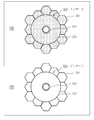
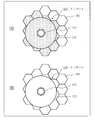
- FIGS. 12 to 14A are plan views of the periphery of the insert 310 in FIG. 11A
- FIGS. 12 to 14B are plan views of the periphery of the insert 310 in FIG. FIG.
- the filler is filled around the flange shaft 313 of the insert 310 regardless of the positional relationship between the insert 310 and the honeycomb core 301.
- a filler is filled in a portion of the honeycomb core 301 adjacent to the insert 310.
- a portion of the honeycomb core 301 that is not adjacent to the insert 310 is not filled with a filler.
- the filler is not filled below the insert 310. That is, the filler is not filled to the lower part of the honeycomb core 301, and the panel 300 after the filler is filled does not become excessively heavy. This is because a flow stop treatment is applied. Specifically, a flow stopping treatment using a GFRP plate is performed.
- GFRP is an abbreviation for Glass Fiber Reinforced Plastic.
- Step S ⁇ b> 106 is a step of separating the edge of the discharge port 212 of the nozzle 211 from the edge of the injection hole 314 of the insert 310. Step S106 will be described below.
- the control unit 132 outputs a pressing stop instruction to the air cylinder 230.
- the air cylinder 230 pulls up the dispenser 210 via the base plate 203 with a force that opposes the weight of the parts including the dispenser 210.
- the control unit 132 outputs a measurement stop instruction to the load cell 240.
- the load cell 240 receives the measurement stop instruction and stops the measurement of the pressing force.
- the control unit 132 outputs an ascending instruction to the moving block 201.
- the moving block 201 receives the ascending instruction and moves the nozzle 211 upward. Specifically, the moving block 201 moves the edge of the discharge port 212 of the nozzle 211 to the edge of the insert 310 until the interval between the edge of the discharge port 212 of the nozzle 211 and the edge of the injection hole 314 of the insert 310 becomes the first interval. Separate from the edge of the injection hole 314.
- Step S107 is a process of recording a work history. Step S107 will be described below.
- the storage unit 139 stores a work history file in advance.
- the work history file includes a work history for each work performed.
- the recording unit 133 records the work history of the work performed in the processing from step S101 to step S106 in the work history file.
- the recording unit 133 records the insert identifier, the filling date and time, and the like in the work history file.
- the insert identifier is an identifier that identifies the insert 310.
- the filling date and time is the date and time when the filler is injected from the injection hole 314 of the insert 310 and filled in the gap 305 between the insert 310 and the honeycomb core 301.
- the filling date and time are the date and time when the filling instruction is output and the date and time when the filling stop instruction is output.
- Embodiment 1 it is possible to automatically fill the filler. Specifically, metal parts for connecting members or equipment are bonded with an adhesive using an automatic filling device to a honeycomb sandwich panel used in a structure such as an artificial satellite, a flying body or an in-vehicle shelter. be able to. This makes it possible to simplify the work of filling the adhesive and the work of leaving a work record.
- the honeycomb core of the honeycomb sandwich panel is a combination of polygons in cross section. Therefore, there is a difference in the amount of adhesive to be filled according to the position of the insert and the shape of the honeycomb core, and the filling amount cannot be uniquely determined.
- the drive head 200 includes a main agent dispenser and a tank, and further includes a curing agent dispenser and a tank.
- the backflow occurs because the main agent and the curing agent are pushed back by the pressure generated when the main agent and the curing agent are discharged and mixed in the static mixer (nozzle 211).
- the dispenser used for the curing agent has a smaller discharging force and tends to cause a backflow. Therefore, it is preferable to narrow the flow path of the curing agent. Thereby, since the discharge pressure of the curing agent increases, it becomes possible to prevent backflow.
- the flow path diameter may be designed so that the force necessary for discharging the curing agent is within the range of the performance of the dispenser.
- the pressing force is measured by the load cell, and the nozzle is pressed against the insert by the air cylinder with an appropriate pressing force. That is, even if the amount of the filler stored in the tank changes, the nozzle can be pressed against the insert with an appropriate pressing force. Therefore, the adhesive does not leak from the insert. Moreover, even if the nozzle is pressed against the insert, the honeycomb sandwich panel is not damaged.
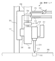
- Embodiment 2 With respect to a mode in which a lifting force that opposes the weight of the component including the dispenser 210 is generated using a spring, a point different from the first embodiment will be mainly described with reference to FIG.
- the air cylinder 230 is illustrated in a simplified manner. Specifically, the first pipe 231, the second pipe 232, the regulator 233 and the piston 234 are omitted. Further, the adjustment guide 261 and the base plate 262 for moving the laser displacement meter 260 are not shown.
- the drive head 200 includes a fixed block 204 and two springs 205 in addition to the elements described in the first embodiment.
- the fixed block 204 is fixed to the moving block 201.
- a dispenser 210 is attached to the fixed block 204.
- the base plate 203 is disposed below the fixed block 204.
- a first tank 221 and a second tank 222 are attached to the upper surface of the base plate 203.
- the first tank 221 is disposed at the left end of the base plate 203, and the second tank 222 is disposed at the right end of the base plate 203.
- a dispenser 210 is attached to the lower surface of the base plate 203.
- the dispenser 210 is disposed in the center of the base plate 203.
- the two springs 205 are provided between the fixed block 204 and the base plate 203.
- the two springs 205 are arranged on the left and right with the dispenser 210 interposed therebetween.
- the two springs 205 pull up the base plate 203 with a pulling force that opposes the weight of the parts including the dispenser 210.
- the parts including the dispenser 210 are the dispenser 210, the base plate 203, the first tank 221, and the second tank 222.
- the part that generates the lifting force against the weight of the part including the dispenser 210 is not the dispenser 210 but two springs 205. In other respects, the automatic filling method is the same as that of the first embodiment.
- the function of the control device 130 may be realized by hardware.
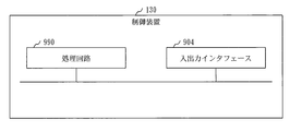
- FIG. 16 shows a configuration when the function of the control device 130 is realized by hardware.
- the control device 130 includes a processing circuit 990.
- the processing circuit 990 is also called a processing circuit.
- the processing circuit 990 is a dedicated electronic circuit that implements functional elements such as the preprocessing unit 131, the control unit 132, the recording unit 133, and the storage unit 139.
- the processing circuit 990 is a single circuit, a composite circuit, a programmed processor, a parallel programmed processor, a logic IC, a GA, an ASIC, an FPGA, or a combination thereof.
- GA is an abbreviation for Gate Array
- ASIC is an abbreviation for Application Specific Integrated Circuit
- FPGA is an abbreviation for Field Programmable Gate Array.
- the control device 130 may include a plurality of processing circuits that replace the processing circuit 990.
- the plurality of processing circuits share the role of functional elements.
- control device 130 may be realized by a combination of software and hardware. That is, some functional elements may be realized by software, and the remaining functional elements may be realized by hardware.
- the functional element may be realized by firmware.
- the embodiment is an example of a preferred embodiment and is not intended to limit the technical scope of the present invention.
- the embodiment may be implemented partially or in combination with other embodiments.
- the procedure described using the arrangement of component elements and the sequence diagram may be changed as appropriate.
- 100 automatic filling device 110 work stage, 120 moving stage, 121 rail, 130 control device, 131 preprocessing unit, 132 control unit, 133 recording unit, 139 storage unit, 200 driving head, 201 moving block, 202 linear guide, 203 Base plate, 204 fixed block, 205 spring, 210 dispenser, 211 nozzle, 212 outlet, 221 first tank, 222 second tank, 230 air cylinder, 231 first pipe, 232 second pipe, 233 regulator, 234 piston, 240 Load cell, 250 camera, 260 laser displacement meter, 261 adjustment guide, 262 base plate, 263 laser light, 300 panel, 301 honeycomb core, 302 skin material, 30 Adhesive sheet, 304 embedded hole, 305 gap, 306 wall, 310 insert, 311 upper flange, 312 lower flange, 313 flange shaft, 314 injection hole, 315 measurement hole, 316 screw hole, 317 shaft hole, 901 processor, 902 memory, 903 Auxiliary storage device, 904 input / output interface,
Landscapes
- Engineering & Computer Science (AREA)
- Mechanical Engineering (AREA)
- Chemical & Material Sciences (AREA)
- General Engineering & Computer Science (AREA)
- Composite Materials (AREA)
- Organic Chemistry (AREA)
- Coating Apparatus (AREA)
Abstract
In the present invention, in a state where an insert (310) is embedded in an embedding hole of a panel (300) and a nozzle (211) of a dispenser (210) is positioned above an injection hole of the insert, an air cylinder (230) presses an edge of a discharge opening (212) of the nozzle against an edge of the injection hole of the insert. Next, the dispenser discharges an adhesive from the discharge opening of the nozzle. The adhesive is inserted from the injection hole of the insert and fills the space between the insert and the panel. Thus, the insert is fixed to the panel.
Description
本発明は、充填剤の充填を自動で行う技術に関するものである。
The present invention relates to a technique for automatically filling a filler.
人工衛星、飛しょう体および車載シェルタ等の構造体には、軽量で且つ高剛性なハニカムサンドイッチパネルが多用される。
ハニカムサンドイッチパネルは、ハニカムコアの両面に表皮材をシート状接着剤で貼りあわせた構造体である。ハニカムサンドイッチパネルには、インサートが埋め込まれる。インサートは、部材あるいは機器をハニカムサンドイッチパネルに連結するためのインタフェースとなる金属部品であり、接着剤が注入される孔を有する。接着剤は充填剤の一例である。
インサートがハニカムサンドイッチパネルに埋め込まれた後、接着剤は、インサートの孔から注入されて、インサートとハニカムコアとの間に充填される。そして、接着剤が硬化すると、インサートがハニカムサンドイッチパネルに固定される。
特許文献1には、インサート充填方法が開示されている。 Lightweight and highly rigid honeycomb sandwich panels are often used for structures such as artificial satellites, flying bodies, and vehicle-mounted shelters.
A honeycomb sandwich panel is a structure in which a skin material is bonded to both sides of a honeycomb core with a sheet adhesive. An insert is embedded in the honeycomb sandwich panel. The insert is a metal part that serves as an interface for connecting a member or device to the honeycomb sandwich panel, and has a hole into which an adhesive is injected. An adhesive is an example of a filler.
After the insert is embedded in the honeycomb sandwich panel, the adhesive is injected from the hole in the insert and filled between the insert and the honeycomb core. When the adhesive is cured, the insert is fixed to the honeycomb sandwich panel.
Patent Document 1 discloses an insert filling method.
インサートを固定するため、2液混合のエポキシ系接着剤が使用されることが多い。2液混合のエポキシ系接着剤は、高粘度の主剤と低粘度の硬化剤とを混合した接着剤である。
主剤と硬化剤との配分の量は決められており、各々の質量が計測された上で主剤と硬化剤とが混合される。 To fix the insert, a two-component mixed epoxy adhesive is often used. The two-component mixed epoxy adhesive is an adhesive in which a high-viscosity main agent and a low-viscosity curing agent are mixed.
The amount of distribution between the main agent and the curing agent is determined, and after the respective masses are measured, the main agent and the curing agent are mixed.
品質管理の観点から、主剤と硬化剤との混合等について作業記録を残す必要がある。そのため、混合の開始時間を記録する必要がある。
接着剤のポットライフは短いため、混合および記録を行う作業は頻繁に発生する。 From the viewpoint of quality control, it is necessary to keep a work record of the mixing of the main agent and the curing agent. Therefore, it is necessary to record the mixing start time.
Since the pot life of the adhesive is short, the work of mixing and recording frequently occurs.
また、充填作業の抜けを無くすため、接着剤がインサートの孔から注入された後、その孔の場所を記録する必要がある。
インサートの数が多い場合、充填作業のみならず充填後の記録作業にも時間を要する。 Also, in order to eliminate missing filling operations, it is necessary to record the location of the hole after the adhesive is injected from the hole in the insert.
When the number of inserts is large, time is required not only for filling work but also for recording work after filling.
本発明は、充填剤の充填を自動で行うことを可能にすることを目的とする。
An object of the present invention is to enable automatic filling of a filler.
本発明の自動充填装置は、
インサートが埋め込まれる埋め込み穴が設けられたパネルが置かれる作業ステージと、
前記インサートに設けられた注入孔から注入される充填剤が吐出される吐出口を有するディスペンサと、
前記作業ステージに前記パネルが置かれ、且つ、前記パネルの前記埋め込み穴に前記インサートが埋め込まれた状態において、前記ディスペンサの前記吐出口の縁を前記インサートの前記注入孔の縁に押し付けるエアシリンダとを備える。 The automatic filling device of the present invention is
A work stage on which a panel with an embedded hole in which the insert is embedded is placed;
A dispenser having a discharge port through which a filler injected from an injection hole provided in the insert is discharged;
An air cylinder that presses an edge of the discharge port of the dispenser against an edge of the injection hole of the insert in a state where the panel is placed on the work stage and the insert is embedded in the embedded hole of the panel; Is provided.
本発明によれば、充填剤の充填を自動で行うことが可能となる。
According to the present invention, it is possible to automatically fill the filler.
実施の形態および図面において、同じ要素または互いに相当する要素には同じ符号を付している。同じ符号が付された要素の説明は適宜に省略または簡略する。図中の矢印はデータまたは処理の流れを主に示している。
In the embodiment and the drawings, the same reference numerals are given to the same elements or elements corresponding to each other. Description of elements having the same reference numerals will be omitted or simplified as appropriate. The arrows in the figure mainly indicate the flow of data or processing.
実施の形態1.
ハニカムサンドイッチパネルとハニカムサンドイッチパネルに埋め込まれたインサートとの隙間に接着剤を自動で充填する形態について、図1から図14に基づいて説明する。 Embodiment 1 FIG.
An embodiment in which an adhesive is automatically filled in the gap between the honeycomb sandwich panel and the insert embedded in the honeycomb sandwich panel will be described with reference to FIGS.
***構成の説明***
図1および図2に基づいて、自動充填装置100の構成を説明する。
図1は側面図であり、図2は平面図である。
X軸は幅方向を示し、Y軸は奥行方向を示し、Z軸は高さ方向を示す。言い換えると、X軸は前後方向を示し、Y軸は左右方向を示し、Z軸は上下方向を示す。
OSは作業ステージ110の原点を示し、OPはパネル300の原点を示す。 *** Explanation of configuration ***
Based on FIG. 1 and FIG. 2, the structure of the automatic filling apparatus 100 is demonstrated.
1 is a side view and FIG. 2 is a plan view.
The X axis indicates the width direction, the Y axis indicates the depth direction, and the Z axis indicates the height direction. In other words, the X-axis indicates the front-rear direction, the Y-axis indicates the left-right direction, and the Z-axis indicates the up-down direction.
O S indicates the origin of thework stage 110, O P indicates the origin of the panel 300.
図1および図2に基づいて、自動充填装置100の構成を説明する。
図1は側面図であり、図2は平面図である。
X軸は幅方向を示し、Y軸は奥行方向を示し、Z軸は高さ方向を示す。言い換えると、X軸は前後方向を示し、Y軸は左右方向を示し、Z軸は上下方向を示す。
OSは作業ステージ110の原点を示し、OPはパネル300の原点を示す。 *** Explanation of configuration ***
Based on FIG. 1 and FIG. 2, the structure of the automatic filling apparatus 100 is demonstrated.
1 is a side view and FIG. 2 is a plan view.
The X axis indicates the width direction, the Y axis indicates the depth direction, and the Z axis indicates the height direction. In other words, the X-axis indicates the front-rear direction, the Y-axis indicates the left-right direction, and the Z-axis indicates the up-down direction.
O S indicates the origin of the
自動充填装置100は、作業ステージ110と、移動ステージ120と、制御装置130と、駆動ヘッド200とを備える。
作業ステージ110は、パネル300が置かれる台である。
移動ステージ120は、駆動ヘッド200が取り付けられるフレームである。移動ステージ120は前後方向に電動で移動する。また、駆動ヘッド200が取り付けられた部分は左右方向に電動で移動する。 The automatic filling apparatus 100 includes awork stage 110, a moving stage 120, a control device 130, and a drive head 200.
Thework stage 110 is a table on which the panel 300 is placed.
The movingstage 120 is a frame to which the driving head 200 is attached. The moving stage 120 moves electrically in the front-rear direction. Further, the portion to which the drive head 200 is attached moves electrically in the left-right direction.
作業ステージ110は、パネル300が置かれる台である。
移動ステージ120は、駆動ヘッド200が取り付けられるフレームである。移動ステージ120は前後方向に電動で移動する。また、駆動ヘッド200が取り付けられた部分は左右方向に電動で移動する。 The automatic filling apparatus 100 includes a
The
The moving
パネル300は、インサート310が埋め込まれる埋め込み穴が設けられた板である(図2を参照)。
パネル300の大きさは、小さいもので0.4m×0.6m程度であり、大きいもので3m×5m程度である。また、パネル300に設けられる埋め込み穴の数は、50個から3000個程度である。埋め込み穴は窪みである。埋め込み穴は、ボール盤などを用いた穴あけ加工によって設けられる。mはメートルを意味する。 Thepanel 300 is a plate provided with an embedding hole in which the insert 310 is embedded (see FIG. 2).
Thepanel 300 has a small size of about 0.4 m × 0.6 m, and a large size of about 3 m × 5 m. Further, the number of embedded holes provided in the panel 300 is about 50 to 3000. The embedding hole is a depression. The embedded hole is provided by drilling using a drilling machine or the like. m means meter.
パネル300の大きさは、小さいもので0.4m×0.6m程度であり、大きいもので3m×5m程度である。また、パネル300に設けられる埋め込み穴の数は、50個から3000個程度である。埋め込み穴は窪みである。埋め込み穴は、ボール盤などを用いた穴あけ加工によって設けられる。mはメートルを意味する。 The
The
図3に基づいて、インサート310の構造を説明する。
図3の(a)は平面図であり、図3の(b)は側面図である。
インサート310は、パネル300に物を連結するための部品である。具体的には、インサート310は金属製の部品である。連結される物とは、何らかの部材または機器である。 The structure of theinsert 310 will be described based on FIG.
FIG. 3A is a plan view, and FIG. 3B is a side view.
Theinsert 310 is a component for connecting an object to the panel 300. Specifically, the insert 310 is a metal part. The connected object is any member or device.
図3の(a)は平面図であり、図3の(b)は側面図である。
インサート310は、パネル300に物を連結するための部品である。具体的には、インサート310は金属製の部品である。連結される物とは、何らかの部材または機器である。 The structure of the
FIG. 3A is a plan view, and FIG. 3B is a side view.
The
インサート310は、上部フランジ311と、下部フランジ312と、フランジ軸313とを備える。
上部フランジ311は上側に配置されるフランジである。上部フランジ311は円板状を成す。上部フランジ311には、中央にねじ穴316が設けられ、ねじ穴316を挟んで2箇所に孔が設けられている。2つの孔はねじ穴316を挟んでほぼ対称に位置する。一方の孔を注入孔314といい、他方の孔を計測孔315という。注入孔314および計測孔315は上部フランジ311を貫通している。
下部フランジ312は下側に配置されるフランジである。下部フランジ312は円板状を成す。下部フランジ312には、中央に軸孔317が設けられている。なお、下部フランジ312は、注入孔314または計測孔315に相当する孔を有さない。
フランジ軸313は、上部フランジ311と下部フランジ312とを繋ぐ軸である。フランジ軸313は筒状を成す。フランジ軸313には、上部フランジ311から途中まで形成されたねじ穴316と、ねじ穴316と連結して下部フランジ312まで貫通した軸孔317とが設けられている。 Theinsert 310 includes an upper flange 311, a lower flange 312, and a flange shaft 313.
Theupper flange 311 is a flange disposed on the upper side. The upper flange 311 has a disk shape. The upper flange 311 is provided with a screw hole 316 at the center and two holes with the screw hole 316 interposed therebetween. The two holes are positioned substantially symmetrically with the screw hole 316 interposed therebetween. One hole is referred to as an injection hole 314 and the other hole is referred to as a measurement hole 315. The injection hole 314 and the measurement hole 315 pass through the upper flange 311.
Thelower flange 312 is a flange disposed on the lower side. The lower flange 312 has a disk shape. A shaft hole 317 is provided at the center of the lower flange 312. The lower flange 312 does not have a hole corresponding to the injection hole 314 or the measurement hole 315.
Theflange shaft 313 is a shaft that connects the upper flange 311 and the lower flange 312. The flange shaft 313 has a cylindrical shape. The flange shaft 313 is provided with a screw hole 316 formed partway from the upper flange 311 and a shaft hole 317 that is connected to the screw hole 316 and penetrates to the lower flange 312.
上部フランジ311は上側に配置されるフランジである。上部フランジ311は円板状を成す。上部フランジ311には、中央にねじ穴316が設けられ、ねじ穴316を挟んで2箇所に孔が設けられている。2つの孔はねじ穴316を挟んでほぼ対称に位置する。一方の孔を注入孔314といい、他方の孔を計測孔315という。注入孔314および計測孔315は上部フランジ311を貫通している。
下部フランジ312は下側に配置されるフランジである。下部フランジ312は円板状を成す。下部フランジ312には、中央に軸孔317が設けられている。なお、下部フランジ312は、注入孔314または計測孔315に相当する孔を有さない。
フランジ軸313は、上部フランジ311と下部フランジ312とを繋ぐ軸である。フランジ軸313は筒状を成す。フランジ軸313には、上部フランジ311から途中まで形成されたねじ穴316と、ねじ穴316と連結して下部フランジ312まで貫通した軸孔317とが設けられている。 The
The
The
The
インサート310の具体的な大きさは以下の通りである。
上部フランジ311および下部フランジ312の直径DMは1cmから10cm程度である。cmはセンチメートルを意味する。
インサート310の高さHは1cmから5cm程度である。なお、インサート310の高さHは、パネル300に設けられた埋め込み穴の深さと同程度である。
実施の形態で示すインサート310の形状および寸法は一例であり、インサート310の形状および寸法は実施の形態で示す形状および寸法と異なっても構わない。 The specific size of theinsert 310 is as follows.
The diameter D M of theupper flange 311 and lower flange 312 are 10cm order of 1 cm. cm means centimeter.
The height H of theinsert 310 is about 1 cm to 5 cm. Note that the height H of the insert 310 is approximately the same as the depth of the embedded hole provided in the panel 300.
The shape and size of theinsert 310 shown in the embodiment is an example, and the shape and size of the insert 310 may be different from the shape and size shown in the embodiment.
上部フランジ311および下部フランジ312の直径DMは1cmから10cm程度である。cmはセンチメートルを意味する。
インサート310の高さHは1cmから5cm程度である。なお、インサート310の高さHは、パネル300に設けられた埋め込み穴の深さと同程度である。
実施の形態で示すインサート310の形状および寸法は一例であり、インサート310の形状および寸法は実施の形態で示す形状および寸法と異なっても構わない。 The specific size of the
The diameter D M of the
The height H of the
The shape and size of the
図4および図5に基づいて、パネル300の構造を説明する。
図4および図5は側断面図である。 The structure of thepanel 300 will be described with reference to FIGS.
4 and 5 are side sectional views.
図4および図5は側断面図である。 The structure of the
4 and 5 are side sectional views.
具体的には、パネル300は、人工衛星などの構造体に用いられるハニカムサンドイッチパネルである。
Specifically, the panel 300 is a honeycomb sandwich panel used for structures such as artificial satellites.
図4に示すように、パネル300は、ハニカムコア301と2枚の表皮材302とを備え、ハニカムコア301を表皮材302で挟んで構成される。
ハニカムコア301は、連結された複数の多角柱(具体的には六角柱)で構成される。なお、複数の多角柱はそれぞれ筒状を成す。
表皮材302は、接着シート303によって、ハニカムコア301の上部と下部とに接着される。具体的な表皮材302は、アルミニウムまたはCFRP(Carbon Fiber Reinforced Plastic)である。接着シート303はシート状の接着剤である。 As shown in FIG. 4, thepanel 300 includes a honeycomb core 301 and two skin materials 302, and the honeycomb core 301 is sandwiched between the skin materials 302.
Thehoneycomb core 301 is composed of a plurality of connected polygonal columns (specifically hexagonal columns). Note that each of the plurality of polygonal columns has a cylindrical shape.
Theskin material 302 is bonded to the upper and lower portions of the honeycomb core 301 by the adhesive sheet 303. A specific skin material 302 is aluminum or CFRP (Carbon Fiber Reinforced Plastic). The adhesive sheet 303 is a sheet-like adhesive.
ハニカムコア301は、連結された複数の多角柱(具体的には六角柱)で構成される。なお、複数の多角柱はそれぞれ筒状を成す。
表皮材302は、接着シート303によって、ハニカムコア301の上部と下部とに接着される。具体的な表皮材302は、アルミニウムまたはCFRP(Carbon Fiber Reinforced Plastic)である。接着シート303はシート状の接着剤である。 As shown in FIG. 4, the
The
The
パネル300は数種類あり、それぞれの厚さTは1cmから5cm程度である。
また、埋め込み穴304の深さDPはパネル300の厚さTよりも浅い。例えば、埋め込み穴304の深さDPはパネル300の厚さTの半分程度である。 There are several types ofpanels 300, and each thickness T is about 1 cm to 5 cm.
The depth D P of the embeddinghole 304 is shallower than the thickness T of the panel 300. For example, the depth D P of the embedding hole 304 is about half the thickness T of the panel 300.
また、埋め込み穴304の深さDPはパネル300の厚さTよりも浅い。例えば、埋め込み穴304の深さDPはパネル300の厚さTの半分程度である。 There are several types of
The depth D P of the embedding
図5に示すように、インサート310が埋め込み穴304に埋め込まれると、インサート310の上部フランジ311の表面と上側の表皮材302の表面とが同程度の高さとなる。
As shown in FIG. 5, when the insert 310 is embedded in the embedding hole 304, the surface of the upper flange 311 of the insert 310 and the surface of the upper skin material 302 have the same height.
インサート310とハニカムコア301との隙間305には、充填剤が充填される。
インサート310とハニカムコア301との隙間305とは、埋め込み穴304に埋め込まれたインサート310と、ハニカムコア301を形成する壁のうちインサート310と隣接する壁306との隙間を意味する。
具体的には、インサート310をハニカムコア301に固定させる接着剤が充填剤として充填される。 Agap 305 between the insert 310 and the honeycomb core 301 is filled with a filler.
Thegap 305 between the insert 310 and the honeycomb core 301 means a gap between the insert 310 embedded in the embedding hole 304 and the wall 306 adjacent to the insert 310 among the walls forming the honeycomb core 301.
Specifically, an adhesive that fixes theinsert 310 to the honeycomb core 301 is filled as a filler.
インサート310とハニカムコア301との隙間305とは、埋め込み穴304に埋め込まれたインサート310と、ハニカムコア301を形成する壁のうちインサート310と隣接する壁306との隙間を意味する。
具体的には、インサート310をハニカムコア301に固定させる接着剤が充填剤として充填される。 A
The
Specifically, an adhesive that fixes the
図6および図7に基づいて、駆動ヘッド200の構成について説明する。
図6は正面図であり、図7は側面図である。
なお、図6では、カメラ250とレーザ変位計260とに関する部分も図示しているが、図7では、カメラ250とレーザ変位計260とに関する部分の図示を省略している。 Based on FIG. 6 and FIG. 7, the configuration of thedrive head 200 will be described.
6 is a front view, and FIG. 7 is a side view.
In FIG. 6, portions related to thecamera 250 and the laser displacement meter 260 are also illustrated, but in FIG. 7, portions related to the camera 250 and the laser displacement meter 260 are not shown.
図6は正面図であり、図7は側面図である。
なお、図6では、カメラ250とレーザ変位計260とに関する部分も図示しているが、図7では、カメラ250とレーザ変位計260とに関する部分の図示を省略している。 Based on FIG. 6 and FIG. 7, the configuration of the
6 is a front view, and FIG. 7 is a side view.
In FIG. 6, portions related to the
駆動ヘッド200は、インサート310とハニカムコア301との隙間305に充填剤を充填する機器である。
The driving head 200 is a device that fills a gap 305 between the insert 310 and the honeycomb core 301 with a filler.
駆動ヘッド200は、ディスペンサ210と、第1タンク221と、第2タンク222と、エアシリンダ230と、ロードセル240と、カメラ250と、レーザ変位計260とを備える。
さらに、駆動ヘッド200は、移動ブロック201と、リニアガイド202と、ベースプレート203とを備える。
さらに、駆動ヘッド200は、調整ガイド261と、ベースプレート262とを備える。 The drivinghead 200 includes a dispenser 210, a first tank 221, a second tank 222, an air cylinder 230, a load cell 240, a camera 250, and a laser displacement meter 260.
Furthermore, thedrive head 200 includes a moving block 201, a linear guide 202, and a base plate 203.
Further, thedrive head 200 includes an adjustment guide 261 and a base plate 262.
さらに、駆動ヘッド200は、移動ブロック201と、リニアガイド202と、ベースプレート203とを備える。
さらに、駆動ヘッド200は、調整ガイド261と、ベースプレート262とを備える。 The driving
Furthermore, the
Further, the
移動ブロック201は、移動ステージ120のレール121に取り付けられており、レール121に沿って上下に電動で移動する。
リニアガイド202は、移動ブロック201に取り付けられており、移動ブロック201が上下に移動すると移動ブロック201と共に上下に移動する。また、リニアガイド202は上下に電動で移動する。
ベースプレート203は、リニアガイド202に取り付けられており、リニアガイド202が上下に移動するとリニアガイド202と共に上下に移動する。 The movingblock 201 is attached to the rail 121 of the moving stage 120, and moves electrically up and down along the rail 121.
Thelinear guide 202 is attached to the moving block 201 and moves up and down together with the moving block 201 when the moving block 201 moves up and down. Moreover, the linear guide 202 moves electrically up and down.
Thebase plate 203 is attached to the linear guide 202, and moves up and down together with the linear guide 202 when the linear guide 202 moves up and down.
リニアガイド202は、移動ブロック201に取り付けられており、移動ブロック201が上下に移動すると移動ブロック201と共に上下に移動する。また、リニアガイド202は上下に電動で移動する。
ベースプレート203は、リニアガイド202に取り付けられており、リニアガイド202が上下に移動するとリニアガイド202と共に上下に移動する。 The moving
The
The
ディスペンサ210は、充填剤を吐出する機器である。
ディスペンサ210は、ノズル211を備える。
ノズル211は、充填剤が吐出される吐出口212を先端に有する。
具体的には、ノズル211は、複数の液体を撹拌して混合させるスタティックミキサーである。 Thedispenser 210 is a device that discharges a filler.
Thedispenser 210 includes a nozzle 211.
Thenozzle 211 has a discharge port 212 through which a filler is discharged at the tip.
Specifically, thenozzle 211 is a static mixer that stirs and mixes a plurality of liquids.
ディスペンサ210は、ノズル211を備える。
ノズル211は、充填剤が吐出される吐出口212を先端に有する。
具体的には、ノズル211は、複数の液体を撹拌して混合させるスタティックミキサーである。 The
The
The
Specifically, the
第1タンク221は、充填剤を構成する第1の液体が格納される容器である。第1の液体は第1タンク221からディスペンサ210に供給される。
第2タンク222は、充填剤を構成する第2の液体が格納される容器である。第2の液体は第2タンク222からディスペンサ210に供給される。
充填剤は、第1の液体と第2の液体とが混合した混合液である。具体的には、充填剤は2液混合のエポキシ系接着剤であり、第1の液体は高粘度の主剤であり、第2の液体は低粘度の硬化剤である。2液混合のエポキシ系接着剤は、高粘度の主剤と低粘度の硬化剤とを混合した接着剤である。なお、ハニカムコア301の壁に微小な孔が生じた場合であっても充填剤が微小な孔から流出しないように、中粘度または高粘度な充填剤が選定される。 The1st tank 221 is a container in which the 1st liquid which constitutes a filler is stored. The first liquid is supplied from the first tank 221 to the dispenser 210.
The2nd tank 222 is a container in which the 2nd liquid which constitutes a filler is stored. The second liquid is supplied from the second tank 222 to the dispenser 210.
The filler is a mixed liquid in which the first liquid and the second liquid are mixed. Specifically, the filler is a two-component mixed epoxy adhesive, the first liquid is a high-viscosity main agent, and the second liquid is a low-viscosity curing agent. The two-component mixed epoxy adhesive is an adhesive in which a high-viscosity main agent and a low-viscosity curing agent are mixed. In addition, even when a minute hole is generated in the wall of thehoneycomb core 301, a filler having a medium viscosity or a high viscosity is selected so that the filler does not flow out of the minute hole.
第2タンク222は、充填剤を構成する第2の液体が格納される容器である。第2の液体は第2タンク222からディスペンサ210に供給される。
充填剤は、第1の液体と第2の液体とが混合した混合液である。具体的には、充填剤は2液混合のエポキシ系接着剤であり、第1の液体は高粘度の主剤であり、第2の液体は低粘度の硬化剤である。2液混合のエポキシ系接着剤は、高粘度の主剤と低粘度の硬化剤とを混合した接着剤である。なお、ハニカムコア301の壁に微小な孔が生じた場合であっても充填剤が微小な孔から流出しないように、中粘度または高粘度な充填剤が選定される。 The
The
The filler is a mixed liquid in which the first liquid and the second liquid are mixed. Specifically, the filler is a two-component mixed epoxy adhesive, the first liquid is a high-viscosity main agent, and the second liquid is a low-viscosity curing agent. The two-component mixed epoxy adhesive is an adhesive in which a high-viscosity main agent and a low-viscosity curing agent are mixed. In addition, even when a minute hole is generated in the wall of the
エアシリンダ230は、ベースプレート203を上下に移動させることによって、ディスペンサ210のノズル211を上下に移動させる機器である。
エアシリンダ230は、第1パイプ231と、第2パイプ232と、レギュレータ233と、ピストン234とを備える。
レギュレータ233は、第1パイプ231に流れる空気と第2パイプ232に流れる空気とを調整することによって、ピストン234を空気圧で上下に移動させる機器である。ピストン234が上下に移動するとベースプレート203と共にディスペンサ210のノズル211が上下に移動する。具体的には、レギュレータ233は電空レギュレータである。 Theair cylinder 230 is a device that moves the nozzle 211 of the dispenser 210 up and down by moving the base plate 203 up and down.
Theair cylinder 230 includes a first pipe 231, a second pipe 232, a regulator 233, and a piston 234.
Theregulator 233 is a device that moves the piston 234 up and down by air pressure by adjusting the air flowing through the first pipe 231 and the air flowing through the second pipe 232. When the piston 234 moves up and down, the nozzle 211 of the dispenser 210 moves up and down together with the base plate 203. Specifically, the regulator 233 is an electropneumatic regulator.
エアシリンダ230は、第1パイプ231と、第2パイプ232と、レギュレータ233と、ピストン234とを備える。
レギュレータ233は、第1パイプ231に流れる空気と第2パイプ232に流れる空気とを調整することによって、ピストン234を空気圧で上下に移動させる機器である。ピストン234が上下に移動するとベースプレート203と共にディスペンサ210のノズル211が上下に移動する。具体的には、レギュレータ233は電空レギュレータである。 The
The
The
ロードセル240は、押し付け力を計測するセンサである。
押し付け力とは、ノズル211の吐出口212の縁がインサート310の注入孔314の縁に押し付けられる力である。
具体的には、ロードセル240は、エアシリンダ230がベースプレート203を押し下げる力を押し付け力として計測する。 Theload cell 240 is a sensor that measures the pressing force.
The pressing force is a force by which the edge of thedischarge port 212 of the nozzle 211 is pressed against the edge of the injection hole 314 of the insert 310.
Specifically, theload cell 240 measures the force by which the air cylinder 230 pushes down the base plate 203 as a pressing force.
押し付け力とは、ノズル211の吐出口212の縁がインサート310の注入孔314の縁に押し付けられる力である。
具体的には、ロードセル240は、エアシリンダ230がベースプレート203を押し下げる力を押し付け力として計測する。 The
The pressing force is a force by which the edge of the
Specifically, the
カメラ250は、ディスペンサ210のノズル211の下方に位置するインサート310を撮影する機器である。
The camera 250 is a device that photographs the insert 310 located below the nozzle 211 of the dispenser 210.
調整ガイド261は、移動ブロック201に取り付けられており、移動ブロック201が上下に移動すると移動ブロック201と共に上下に移動する。また、調整ガイド261は上下左右に電動で移動する。
ベースプレート262は、調整ガイド261に取り付けられており、調整ガイド261が移動すると調整ガイド261と共に移動する。 Theadjustment guide 261 is attached to the moving block 201 and moves up and down together with the moving block 201 when the moving block 201 moves up and down. Further, the adjustment guide 261 moves electrically up, down, left and right.
Thebase plate 262 is attached to the adjustment guide 261 and moves together with the adjustment guide 261 when the adjustment guide 261 moves.
ベースプレート262は、調整ガイド261に取り付けられており、調整ガイド261が移動すると調整ガイド261と共に移動する。 The
The
レーザ変位計260は、ディスペンサ210のノズル211の下方に向けてレーザ光を出射して反射点までの距離を計測する機器である。反射点とは、レーザ光を反射した地点である。
具体的には、レーザ変位計260は、ノズル211の下方に位置するインサート310の計測孔315に向けてレーザ光を出射し、インサート310の注入孔314から注入された充填剤の液面までの距離を計測する。 Thelaser displacement meter 260 is a device that emits laser light toward the lower side of the nozzle 211 of the dispenser 210 and measures the distance to the reflection point. The reflection point is a point where the laser beam is reflected.
Specifically, thelaser displacement meter 260 emits a laser beam toward the measurement hole 315 of the insert 310 located below the nozzle 211, and reaches the liquid level of the filler injected from the injection hole 314 of the insert 310. Measure distance.
具体的には、レーザ変位計260は、ノズル211の下方に位置するインサート310の計測孔315に向けてレーザ光を出射し、インサート310の注入孔314から注入された充填剤の液面までの距離を計測する。 The
Specifically, the
図8に基づいて、制御装置130の構成を説明する。
制御装置130は、移動ステージ120と駆動ヘッド200とを制御するコンピュータである。
制御装置130は、プロセッサ901とメモリ902と補助記憶装置903と入出力インタフェース904といったハードウェアを備える。これらのハードウェアは、信号線を介して互いに接続されている。 Based on FIG. 8, the structure of thecontrol apparatus 130 is demonstrated.
Thecontrol device 130 is a computer that controls the moving stage 120 and the driving head 200.
Thecontrol device 130 includes hardware such as a processor 901, a memory 902, an auxiliary storage device 903, and an input / output interface 904. These hardwares are connected to each other via signal lines.
制御装置130は、移動ステージ120と駆動ヘッド200とを制御するコンピュータである。
制御装置130は、プロセッサ901とメモリ902と補助記憶装置903と入出力インタフェース904といったハードウェアを備える。これらのハードウェアは、信号線を介して互いに接続されている。 Based on FIG. 8, the structure of the
The
The
プロセッサ901は、演算処理を行うIC(Integrated Circuit)であり、他のハードウェアを制御する。具体的には、プロセッサ901は、CPU(Central Processing Unit)である。
メモリ902は揮発性の記憶装置である。メモリ902は、主記憶装置またはメインメモリとも呼ばれる。具体的には、メモリ902はRAM(Random Access Memory)である。
補助記憶装置903は不揮発性の記憶装置である。具体的には、補助記憶装置903は、ROM、HDDまたはフラッシュメモリである。ROMはRead Only Memoryの略称であり、HDDはHard Disk Driveの略称である。 Theprocessor 901 is an IC (Integrated Circuit) that performs arithmetic processing, and controls other hardware. Specifically, the processor 901 is a CPU (Central Processing Unit).
Thememory 902 is a volatile storage device. The memory 902 is also called main memory or main memory. Specifically, the memory 902 is a RAM (Random Access Memory).
Theauxiliary storage device 903 is a nonvolatile storage device. Specifically, the auxiliary storage device 903 is a ROM, HDD, or flash memory. ROM is an abbreviation for Read Only Memory, and HDD is an abbreviation for Hard Disk Drive.
メモリ902は揮発性の記憶装置である。メモリ902は、主記憶装置またはメインメモリとも呼ばれる。具体的には、メモリ902はRAM(Random Access Memory)である。
補助記憶装置903は不揮発性の記憶装置である。具体的には、補助記憶装置903は、ROM、HDDまたはフラッシュメモリである。ROMはRead Only Memoryの略称であり、HDDはHard Disk Driveの略称である。 The
The
The
入出力インタフェース904は、移動ステージ120に繋がったケーブルと駆動ヘッド200に繋がったケーブルとが接続されるポートである。
The input / output interface 904 is a port to which a cable connected to the moving stage 120 and a cable connected to the driving head 200 are connected.
制御装置130は、前処理部131と、制御部132と、記録部133といった機能要素を備える。機能要素とは、制御装置130の機能を構成する要素である。機能要素はソフトウェアで実現される。それぞれの機能要素については後述する。
The control device 130 includes functional elements such as a preprocessing unit 131, a control unit 132, and a recording unit 133. The functional element is an element that constitutes a function of the control device 130. Functional elements are realized by software. Each functional element will be described later.
補助記憶装置903には、機能要素を実現するプログラムが記憶されている。機能要素を実現するプログラムは、メモリ902にロードされて、プロセッサ901によって実行される。
さらに、補助記憶装置903にはOS(Operating System)が記憶されている。OSの少なくとも一部は、メモリ902にロードされて、プロセッサ901によって実行される。
つまり、プロセッサ901は、OSを実行しながら、機能要素を実現するプログラムを実行する。
機能要素を実現するプログラムを実行して得られるデータは、メモリ902、補助記憶装置903、プロセッサ901内のレジスタまたはプロセッサ901内のキャッシュメモリといった記憶装置に記憶される。 Theauxiliary storage device 903 stores a program that realizes functional elements. A program that implements functional elements is loaded into the memory 902 and executed by the processor 901.
Further, theauxiliary storage device 903 stores an OS (Operating System). At least a part of the OS is loaded into the memory 902 and executed by the processor 901.
That is, theprocessor 901 executes a program that realizes functional elements while executing the OS.
Data obtained by executing a program that implements functional elements is stored in a storage device such as thememory 902, the auxiliary storage device 903, a register in the processor 901, or a cache memory in the processor 901.
さらに、補助記憶装置903にはOS(Operating System)が記憶されている。OSの少なくとも一部は、メモリ902にロードされて、プロセッサ901によって実行される。
つまり、プロセッサ901は、OSを実行しながら、機能要素を実現するプログラムを実行する。
機能要素を実現するプログラムを実行して得られるデータは、メモリ902、補助記憶装置903、プロセッサ901内のレジスタまたはプロセッサ901内のキャッシュメモリといった記憶装置に記憶される。 The
Further, the
That is, the
Data obtained by executing a program that implements functional elements is stored in a storage device such as the
メモリ902はデータを記憶する記憶部139として機能する。但し、他の記憶装置が、メモリ902の代わりに、又は、メモリ902と共に、記憶部139として機能してもよい。
The memory 902 functions as a storage unit 139 that stores data. However, another storage device may function as the storage unit 139 instead of the memory 902 or together with the memory 902.
制御装置130は、プロセッサ901を代替する複数のプロセッサを備えてもよい。複数のプロセッサは、機能要素を実現するプログラムの実行を分担する。
機能要素を実現するプログラムは、磁気ディスク、光ディスクまたはフラッシュメモリ等の不揮発性の記憶媒体にコンピュータ読み取り可能に記憶することができる。不揮発性の記憶媒体は、一時的でない有形の媒体である。 Thecontrol device 130 may include a plurality of processors that replace the processor 901. The plurality of processors share the execution of programs that implement functional elements.
The program for realizing the functional elements can be stored in a computer-readable manner in a nonvolatile storage medium such as a magnetic disk, an optical disk, or a flash memory. A non-volatile storage medium is a tangible medium that is not temporary.
機能要素を実現するプログラムは、磁気ディスク、光ディスクまたはフラッシュメモリ等の不揮発性の記憶媒体にコンピュータ読み取り可能に記憶することができる。不揮発性の記憶媒体は、一時的でない有形の媒体である。 The
The program for realizing the functional elements can be stored in a computer-readable manner in a nonvolatile storage medium such as a magnetic disk, an optical disk, or a flash memory. A non-volatile storage medium is a tangible medium that is not temporary.
***動作の説明***
自動充填装置100の動作は自動充填方法に相当する。
制御装置130の動作は充填制御方法に相当する。充填制御方法の手順は充填制御プログラムの手順に相当する。
前処理部131、制御部132および記録部133によって実行される処理は、それぞれ前処理、制御処理および記録処理という。 *** Explanation of operation ***
The operation of the automatic filling apparatus 100 corresponds to an automatic filling method.
The operation of thecontrol device 130 corresponds to a filling control method. The procedure of the filling control method corresponds to the procedure of the filling control program.
Processes executed by thepreprocessing unit 131, the control unit 132, and the recording unit 133 are referred to as preprocessing, control processing, and recording processing, respectively.
自動充填装置100の動作は自動充填方法に相当する。
制御装置130の動作は充填制御方法に相当する。充填制御方法の手順は充填制御プログラムの手順に相当する。
前処理部131、制御部132および記録部133によって実行される処理は、それぞれ前処理、制御処理および記録処理という。 *** Explanation of operation ***
The operation of the automatic filling apparatus 100 corresponds to an automatic filling method.
The operation of the
Processes executed by the
自動充填方法を説明する前に自動充填方法の前処理について説明する。
自動充填方法の前処理は、ノズル211の吐出口212の座標値を示す位置情報を補正する処理である。位置情報は制御装置130に予め記憶されている。初期の位置情報における座標の原点は作業ステージ110の原点OS(図2を参照)である。 Before explaining the automatic filling method, preprocessing of the automatic filling method will be explained.
The pre-processing of the automatic filling method is a process of correcting position information indicating the coordinate value of thedischarge port 212 of the nozzle 211. The position information is stored in the control device 130 in advance. The origin of coordinates in the initial position information is the origin O S of the work stage 110 (see FIG. 2).
自動充填方法の前処理は、ノズル211の吐出口212の座標値を示す位置情報を補正する処理である。位置情報は制御装置130に予め記憶されている。初期の位置情報における座標の原点は作業ステージ110の原点OS(図2を参照)である。 Before explaining the automatic filling method, preprocessing of the automatic filling method will be explained.
The pre-processing of the automatic filling method is a process of correcting position information indicating the coordinate value of the
自動充填方法の前処理は、作業ステージ110にパネル300が置かれ、且つ、パネル300の埋め込み穴304にインサート310が埋め込まれた状態において行われる。
なお、インサート310は、予め決められた向きで埋め込み穴304に埋め込まれている。具体的には、注入孔314と計測孔315とがY軸の方向に並ぶように、インサート310は埋め込み穴304に埋め込まれている。
インサート310の向きは、ある程度、統一する必要がある。つまり、注入孔314と計測孔315とを結んだ線がY軸に対して成す角度が小さくなるように、インサート310を埋め込み穴304に埋め込む必要がある。具体的には、注入孔314と計測孔315とを結んだ線がY軸に対して成す角度がマイナス10度からプラス10度の範囲内の大きさになる必要がある。 Preprocessing of the automatic filling method is performed in a state where thepanel 300 is placed on the work stage 110 and the insert 310 is embedded in the embedding hole 304 of the panel 300.
Theinsert 310 is embedded in the embedding hole 304 in a predetermined direction. Specifically, the insert 310 is embedded in the embedded hole 304 so that the injection hole 314 and the measurement hole 315 are aligned in the Y-axis direction.
The orientation of theinsert 310 needs to be unified to some extent. That is, it is necessary to embed the insert 310 in the embedding hole 304 so that the angle formed by the line connecting the injection hole 314 and the measurement hole 315 with respect to the Y axis becomes small. Specifically, the angle formed by the line connecting the injection hole 314 and the measurement hole 315 with respect to the Y axis needs to be within a range of minus 10 degrees to plus 10 degrees.
なお、インサート310は、予め決められた向きで埋め込み穴304に埋め込まれている。具体的には、注入孔314と計測孔315とがY軸の方向に並ぶように、インサート310は埋め込み穴304に埋め込まれている。
インサート310の向きは、ある程度、統一する必要がある。つまり、注入孔314と計測孔315とを結んだ線がY軸に対して成す角度が小さくなるように、インサート310を埋め込み穴304に埋め込む必要がある。具体的には、注入孔314と計測孔315とを結んだ線がY軸に対して成す角度がマイナス10度からプラス10度の範囲内の大きさになる必要がある。 Preprocessing of the automatic filling method is performed in a state where the
The
The orientation of the
自動充填方法の前処理において、自動充填装置100は以下のように動作する。
記憶部139は、インサート座標データを予め記憶している。インサート座標データは、それぞれのインサート310の座標値を含んでいる。インサート座標データにおける座標の原点は、パネル300の原点OPである。具体的には、インサート座標データはCADデータである。CADはComputer Aided Designの略称である。
まず、前処理部131は、インサート座標データから基準インサートの座標値を2点選択する。基準インサートは基準となるインサート310である。具体的には、基準インサートは、原点OPに比較的近いインサート310および原点OPから比較的遠いインサート310である。
次に、前処理部131は、基準インサートの座標値に基づいて移動量を算出する。
次に、前処理部131は、算出された移動量に基づいて、移動ステージ120と移動ブロック201とに対して移動指示を出力する。移動ステージ120および移動ブロック201は、移動指示を受けて、ノズル211を基準インサートの上方に移動させる。
次に、前処理部131は、カメラ250に対して撮影指示を出力する。カメラ250は、撮影指示を受けて、基準インサートを撮影して画像を得る。そして、カメラ250は、得られた画像を前処理部131に対して出力する。
次に、前処理部131は、画像を受けて、画像における基準インサートの位置ずれ量と角度ずれ量とを算出する。基準インサートの位置ずれ量とは、インサート座標データにおける基準インサートの座標値と画像における基準インサートの座標値とのずれの大きさである。基準インサートの角度ずれ量とは、インサート座標データにおける2つの基準インサートの2点の座標値を結んで得られる線が、画像における2つの基準インサートの2点の座標値を結んで得られる線に対して成す角度である。
そして、前処理部131は、インサート座標データにおける基準インサートの座標値を、インサート座標データにおける座標軸を角度ずれ量だけ回転させた場合の座標値に変換する。その後、前処理部131は、インサート座標データにおける基準インサートの座標値に位置ずれ量を加算する。 In the pretreatment of the automatic filling method, the automatic filling apparatus 100 operates as follows.
Thestorage unit 139 stores insert coordinate data in advance. The insert coordinate data includes the coordinate value of each insert 310. The origin of coordinates in the insert coordinate data, the origin O P of the panel 300. Specifically, the insert coordinate data is CAD data. CAD is an abbreviation for Computer Aided Design.
First, thepreprocessing unit 131 selects two coordinate values of the reference insert from the insert coordinate data. The reference insert is a reference insert 310. Specifically, the reference insert is relatively far insert 310 from the origin O P relatively close insert 310 and the origin O P.
Next, thepreprocessing unit 131 calculates a movement amount based on the coordinate value of the reference insert.
Next, thepreprocessing unit 131 outputs a movement instruction to the movement stage 120 and the movement block 201 based on the calculated movement amount. In response to the movement instruction, the movement stage 120 and the movement block 201 move the nozzle 211 above the reference insert.
Next, thepreprocessing unit 131 outputs a shooting instruction to the camera 250. In response to the shooting instruction, the camera 250 captures the reference insert to obtain an image. Then, the camera 250 outputs the obtained image to the preprocessing unit 131.
Next, thepreprocessing unit 131 receives the image, and calculates the positional deviation amount and the angular deviation amount of the reference insert in the image. The positional deviation amount of the reference insert is the magnitude of deviation between the coordinate value of the reference insert in the insert coordinate data and the coordinate value of the reference insert in the image. The angle deviation amount of the reference insert is a line obtained by connecting the coordinate values of the two reference inserts of the two reference inserts in the insert coordinate data to the line obtained by connecting the coordinate values of the two reference inserts of the two reference inserts in the image. It is the angle formed with respect to it.
Then, thepreprocessing unit 131 converts the coordinate value of the reference insert in the insert coordinate data into a coordinate value when the coordinate axis in the insert coordinate data is rotated by the amount of angular deviation. Thereafter, the preprocessing unit 131 adds the amount of displacement to the coordinate value of the reference insert in the insert coordinate data.
記憶部139は、インサート座標データを予め記憶している。インサート座標データは、それぞれのインサート310の座標値を含んでいる。インサート座標データにおける座標の原点は、パネル300の原点OPである。具体的には、インサート座標データはCADデータである。CADはComputer Aided Designの略称である。
まず、前処理部131は、インサート座標データから基準インサートの座標値を2点選択する。基準インサートは基準となるインサート310である。具体的には、基準インサートは、原点OPに比較的近いインサート310および原点OPから比較的遠いインサート310である。
次に、前処理部131は、基準インサートの座標値に基づいて移動量を算出する。
次に、前処理部131は、算出された移動量に基づいて、移動ステージ120と移動ブロック201とに対して移動指示を出力する。移動ステージ120および移動ブロック201は、移動指示を受けて、ノズル211を基準インサートの上方に移動させる。
次に、前処理部131は、カメラ250に対して撮影指示を出力する。カメラ250は、撮影指示を受けて、基準インサートを撮影して画像を得る。そして、カメラ250は、得られた画像を前処理部131に対して出力する。
次に、前処理部131は、画像を受けて、画像における基準インサートの位置ずれ量と角度ずれ量とを算出する。基準インサートの位置ずれ量とは、インサート座標データにおける基準インサートの座標値と画像における基準インサートの座標値とのずれの大きさである。基準インサートの角度ずれ量とは、インサート座標データにおける2つの基準インサートの2点の座標値を結んで得られる線が、画像における2つの基準インサートの2点の座標値を結んで得られる線に対して成す角度である。
そして、前処理部131は、インサート座標データにおける基準インサートの座標値を、インサート座標データにおける座標軸を角度ずれ量だけ回転させた場合の座標値に変換する。その後、前処理部131は、インサート座標データにおける基準インサートの座標値に位置ずれ量を加算する。 In the pretreatment of the automatic filling method, the automatic filling apparatus 100 operates as follows.
The
First, the
Next, the
Next, the
Next, the
Next, the
Then, the
図9に基づいて、自動充填方法を説明する。
自動充填方法は、インサート310とハニカムコア301との隙間305に充填剤を充填する方法である。
自動充填方法は、上記の前処理の後に行われる。
自動充填方法において、ステップS101からステップS107までの処理は、インサート310毎に実行される。 Based on FIG. 9, the automatic filling method will be described.
The automatic filling method is a method of filling thegap 305 between the insert 310 and the honeycomb core 301 with a filler.
The automatic filling method is performed after the above pretreatment.
In the automatic filling method, the processing from step S101 to step S107 is executed for eachinsert 310.
自動充填方法は、インサート310とハニカムコア301との隙間305に充填剤を充填する方法である。
自動充填方法は、上記の前処理の後に行われる。
自動充填方法において、ステップS101からステップS107までの処理は、インサート310毎に実行される。 Based on FIG. 9, the automatic filling method will be described.
The automatic filling method is a method of filling the
The automatic filling method is performed after the above pretreatment.
In the automatic filling method, the processing from step S101 to step S107 is executed for each
ステップS101は、ノズル211をインサート310の上方に移動させる工程である。以下にステップS101を説明する。
まず、制御部132は、インサート310の座標値をインサート座標データから選択する。
次に、制御部132は、位置情報とインサート310の座標値とに基づいて移動量を算出する。
次に、制御部132は、算出された移動量に基づいて、移動ステージ120に対して移動指示を出力する。また、制御部132は、算出された移動量に基づいて、位置情報を更新する。
そして、移動ステージ120は、移動指示を受けて、ノズル211をインサート310の上方に移動させる。
なお、エアシリンダ230は、ディスペンサ210を含む部品の自重に対抗する力でベースプレート203を介してディスペンサ210を引き上げている。これにより、ディスペンサ210を含む部品は自重によって下降しない。ディスペンサ210を含む部品とは、ディスペンサ210とベースプレート203と第1タンク221と第2タンク222とベースプレート203とリニアガイド202である。 Step S <b> 101 is a step of moving thenozzle 211 above the insert 310. Step S101 will be described below.
First, thecontrol unit 132 selects the coordinate value of the insert 310 from the insert coordinate data.
Next, thecontrol unit 132 calculates a movement amount based on the position information and the coordinate value of the insert 310.
Next, thecontrol unit 132 outputs a movement instruction to the movement stage 120 based on the calculated movement amount. Further, the control unit 132 updates the position information based on the calculated movement amount.
In response to the movement instruction, the movingstage 120 moves the nozzle 211 above the insert 310.
Theair cylinder 230 pulls up the dispenser 210 via the base plate 203 with a force that opposes the weight of the parts including the dispenser 210. Thereby, the parts including the dispenser 210 do not descend due to their own weight. The components including the dispenser 210 are the dispenser 210, the base plate 203, the first tank 221, the second tank 222, the base plate 203, and the linear guide 202.
まず、制御部132は、インサート310の座標値をインサート座標データから選択する。
次に、制御部132は、位置情報とインサート310の座標値とに基づいて移動量を算出する。
次に、制御部132は、算出された移動量に基づいて、移動ステージ120に対して移動指示を出力する。また、制御部132は、算出された移動量に基づいて、位置情報を更新する。
そして、移動ステージ120は、移動指示を受けて、ノズル211をインサート310の上方に移動させる。
なお、エアシリンダ230は、ディスペンサ210を含む部品の自重に対抗する力でベースプレート203を介してディスペンサ210を引き上げている。これにより、ディスペンサ210を含む部品は自重によって下降しない。ディスペンサ210を含む部品とは、ディスペンサ210とベースプレート203と第1タンク221と第2タンク222とベースプレート203とリニアガイド202である。 Step S <b> 101 is a step of moving the
First, the
Next, the
Next, the
In response to the movement instruction, the moving
The
ステップS102は、インサート310における注入孔314のずれ量とインサート310における計測孔315のずれ量とを計測する工程である。注入孔314のずれ量とは注入孔314用の基準位置と注入孔314の位置とのずれの大きさである。計測孔315のずれ量とは計測孔315用の基準位置と計測孔315の位置とのXY座標のずれの大きさである。以下にステップS102を説明する。
まず、制御部132は、カメラ250に対して撮影指示を出力する。
次に、カメラ250は、撮影指示を受けて、インサート310を撮影して画像を得る。
次に、カメラ250は、画像からインサート310の注入孔314を検出し、画像におけるインサート310の注入孔314の位置を算出する。また、カメラ250は、画像からインサート310の計測孔315を検出し、画像におけるインサート310の計測孔315の位置を算出する。
次に、カメラ250は、画像におけるインサート310の注入孔314の位置と画像におけるインサート310の計測孔315の位置とを示す検出結果を制御部132に対して出力する。制御部132は、検出結果を受ける。
そして、制御部132は、画像におけるインサート310の注入孔314の位置に基づいて、インサート310における注入孔314のずれ量を算出する。また、制御部132は、画像におけるインサート310の計測孔315の位置に基づいて、インサート310における計測孔315のずれ量を算出する。 Step S102 is a step of measuring the deviation amount of theinjection hole 314 in the insert 310 and the deviation amount of the measurement hole 315 in the insert 310. The shift amount of the injection hole 314 is the amount of shift between the reference position for the injection hole 314 and the position of the injection hole 314. The amount of deviation of the measurement hole 315 is the magnitude of deviation of the XY coordinates between the reference position for the measurement hole 315 and the position of the measurement hole 315. Step S102 will be described below.
First, thecontrol unit 132 outputs a shooting instruction to the camera 250.
Next, thecamera 250 receives the shooting instruction and takes an image of the insert 310 to obtain an image.
Next, thecamera 250 detects the injection hole 314 of the insert 310 from the image, and calculates the position of the injection hole 314 of the insert 310 in the image. The camera 250 detects the measurement hole 315 of the insert 310 from the image, and calculates the position of the measurement hole 315 of the insert 310 in the image.
Next, thecamera 250 outputs a detection result indicating the position of the injection hole 314 of the insert 310 in the image and the position of the measurement hole 315 of the insert 310 in the image to the control unit 132. The control unit 132 receives the detection result.
And thecontrol part 132 calculates the deviation | shift amount of the injection hole 314 in the insert 310 based on the position of the injection hole 314 of the insert 310 in an image. Moreover, the control part 132 calculates the deviation | shift amount of the measurement hole 315 in the insert 310 based on the position of the measurement hole 315 of the insert 310 in an image.
まず、制御部132は、カメラ250に対して撮影指示を出力する。
次に、カメラ250は、撮影指示を受けて、インサート310を撮影して画像を得る。
次に、カメラ250は、画像からインサート310の注入孔314を検出し、画像におけるインサート310の注入孔314の位置を算出する。また、カメラ250は、画像からインサート310の計測孔315を検出し、画像におけるインサート310の計測孔315の位置を算出する。
次に、カメラ250は、画像におけるインサート310の注入孔314の位置と画像におけるインサート310の計測孔315の位置とを示す検出結果を制御部132に対して出力する。制御部132は、検出結果を受ける。
そして、制御部132は、画像におけるインサート310の注入孔314の位置に基づいて、インサート310における注入孔314のずれ量を算出する。また、制御部132は、画像におけるインサート310の計測孔315の位置に基づいて、インサート310における計測孔315のずれ量を算出する。 Step S102 is a step of measuring the deviation amount of the
First, the
Next, the
Next, the
Next, the
And the
ステップS103は、ノズル211の位置とレーザ変位計260の位置とを補正する工程である。以下にステップS103を説明する。
まず、制御部132は、インサート310における注入孔314のずれ量に基づいて、移動ステージ120に対して移動指示を出力する。また、制御部132は、インサート310の注入孔314のずれ量に基づいて、位置情報を更新する。
そして、移動ステージ120は、移動指示を受けて、ノズル211の吐出口212をインサート310の注入孔314の上方に移動させる。
さらに、制御部132は、インサート310における計測孔315のずれ量に基づいて、調整ガイド261に対して移動指示を出力する。
そして、調整ガイド261は、移動指示を受けて、レーザ変位計260を移動させる。具体的には、調整ガイド261は、レーザ光が計測孔315に向けて出射される位置にレーザ変位計260を移動させる。 Step S103 is a step of correcting the position of thenozzle 211 and the position of the laser displacement meter 260. Step S103 will be described below.
First, thecontrol unit 132 outputs a movement instruction to the moving stage 120 based on the amount of deviation of the injection hole 314 in the insert 310. Further, the control unit 132 updates the position information based on the shift amount of the injection hole 314 of the insert 310.
In response to the movement instruction, the movingstage 120 moves the discharge port 212 of the nozzle 211 above the injection hole 314 of the insert 310.
Further, thecontrol unit 132 outputs a movement instruction to the adjustment guide 261 based on the shift amount of the measurement hole 315 in the insert 310.
Then, theadjustment guide 261 receives the movement instruction and moves the laser displacement meter 260. Specifically, the adjustment guide 261 moves the laser displacement meter 260 to a position where the laser light is emitted toward the measurement hole 315.
まず、制御部132は、インサート310における注入孔314のずれ量に基づいて、移動ステージ120に対して移動指示を出力する。また、制御部132は、インサート310の注入孔314のずれ量に基づいて、位置情報を更新する。
そして、移動ステージ120は、移動指示を受けて、ノズル211の吐出口212をインサート310の注入孔314の上方に移動させる。
さらに、制御部132は、インサート310における計測孔315のずれ量に基づいて、調整ガイド261に対して移動指示を出力する。
そして、調整ガイド261は、移動指示を受けて、レーザ変位計260を移動させる。具体的には、調整ガイド261は、レーザ光が計測孔315に向けて出射される位置にレーザ変位計260を移動させる。 Step S103 is a step of correcting the position of the
First, the
In response to the movement instruction, the moving
Further, the
Then, the
ステップS104は、ノズル211の吐出口212の縁をインサート310の注入孔314の縁に押し付ける工程である。以下にステップS104を説明する。
まず、制御部132は、移動ブロック201に対して下降指示を出力する。移動ブロック201は、下降指示を受けて、ノズル211を下方に移動させる。具体的には、移動ブロック201は、ノズル211の吐出口212の縁がインサート310の注入孔314の縁と接触するまで下降指示を出力する。
次に、制御部132は、ロードセル240に対して計測指示を出力する。ロードセル240は、計測指示を受けて、押し付け力の計測を開始する。押し付け力とは、エアシリンダ230からノズル211に与えられる力である。押し付け力の計測が開始された後、押し付け力の計測が停止されるまで、ロードセル240は、押し付け力の計測を繰り返し、押し付け力を計測する度に制御部132に対して計測結果を出力する。この計測結果は計測された押し付け力を示す。
そして、制御部132は、計測結果を受ける度に、計測結果が示す押し付け力に基づいてエアシリンダ230に対して押し付け指示を出力する。エアシリンダ230は、押し付け指示を受けて、ベースプレート203を介してディスペンサ210を押し下げる。これにより、押し付け力が押し付け力範囲に収まる程度にノズル211の吐出口212の縁がインサート310の注入孔314の縁に押し付けられる。 Step S104 is a step of pressing the edge of thedischarge port 212 of the nozzle 211 against the edge of the injection hole 314 of the insert 310. Step S104 will be described below.
First, thecontrol unit 132 outputs a lowering instruction to the moving block 201. The movement block 201 receives the lowering instruction and moves the nozzle 211 downward. Specifically, the moving block 201 outputs a lowering instruction until the edge of the discharge port 212 of the nozzle 211 comes into contact with the edge of the injection hole 314 of the insert 310.
Next, thecontrol unit 132 outputs a measurement instruction to the load cell 240. In response to the measurement instruction, the load cell 240 starts measuring the pressing force. The pressing force is a force applied from the air cylinder 230 to the nozzle 211. After the measurement of the pressing force is started, the load cell 240 repeats the measurement of the pressing force until the measurement of the pressing force is stopped, and outputs the measurement result to the control unit 132 every time the pressing force is measured. This measurement result shows the measured pressing force.
Then, every time thecontrol unit 132 receives the measurement result, the control unit 132 outputs a pressing instruction to the air cylinder 230 based on the pressing force indicated by the measurement result. In response to the pressing instruction, the air cylinder 230 pushes down the dispenser 210 via the base plate 203. Thereby, the edge of the discharge port 212 of the nozzle 211 is pressed against the edge of the injection hole 314 of the insert 310 to such an extent that the pressing force falls within the pressing force range.
まず、制御部132は、移動ブロック201に対して下降指示を出力する。移動ブロック201は、下降指示を受けて、ノズル211を下方に移動させる。具体的には、移動ブロック201は、ノズル211の吐出口212の縁がインサート310の注入孔314の縁と接触するまで下降指示を出力する。
次に、制御部132は、ロードセル240に対して計測指示を出力する。ロードセル240は、計測指示を受けて、押し付け力の計測を開始する。押し付け力とは、エアシリンダ230からノズル211に与えられる力である。押し付け力の計測が開始された後、押し付け力の計測が停止されるまで、ロードセル240は、押し付け力の計測を繰り返し、押し付け力を計測する度に制御部132に対して計測結果を出力する。この計測結果は計測された押し付け力を示す。
そして、制御部132は、計測結果を受ける度に、計測結果が示す押し付け力に基づいてエアシリンダ230に対して押し付け指示を出力する。エアシリンダ230は、押し付け指示を受けて、ベースプレート203を介してディスペンサ210を押し下げる。これにより、押し付け力が押し付け力範囲に収まる程度にノズル211の吐出口212の縁がインサート310の注入孔314の縁に押し付けられる。 Step S104 is a step of pressing the edge of the
First, the
Next, the
Then, every time the
図10に基づいて、ステップS104の後のパネル300とインサート310とノズル211との状態を説明する。
インサート310は、パネル300の埋め込み穴304に埋め込まれている。
ノズル211の吐出口212の縁は、インサート310の注入孔314の縁に押し付けられている。 Based on FIG. 10, the state of thepanel 300, the insert 310, and the nozzle 211 after step S104 will be described.
Theinsert 310 is embedded in the embedded hole 304 of the panel 300.
The edge of thedischarge port 212 of the nozzle 211 is pressed against the edge of the injection hole 314 of the insert 310.
インサート310は、パネル300の埋め込み穴304に埋め込まれている。
ノズル211の吐出口212の縁は、インサート310の注入孔314の縁に押し付けられている。 Based on FIG. 10, the state of the
The
The edge of the
図9に戻り、ステップS105から説明を続ける。
ステップS105は、インサート310とハニカムコア301との隙間305に充填剤を充填する工程である。以下にステップS105を説明する。
まず、制御部132は、レーザ変位計260に対して計測指示を出力する。レーザ変位計260は、計測指示を受けて、液面距離の計測を開始する。液面距離とは、インサート310の注入孔314から注入された充填剤の液面までの距離である。具体的には、レーザ変位計260は、インサート310の計測孔315に向けてレーザ光を出射し、充填剤の液面に反射したレーザ光を受光する。そして、レーザ変位計260は、レーザ光を出射してから受光するまでの時間に基づいて、液面距離を算出する。液面距離の計測が開始された後、液面距離の計測が停止されるまで、レーザ変位計260は、液面距離の計測を繰り返し、液面距離を計測する度に制御部132に対して計測結果を出力する。この計測結果は計測された液面距離を示す。
次に、制御部132は、ディスペンサ210に対して充填指示を出力する。ディスペンサ210は、充填指示を受けて、充填剤の吐出を開始する。充填剤の吐出が開始された後、充填剤の吐出が停止されるまで、ディスペンサ210は、ノズル211の吐出口212から充填剤を吐出する。なお、充填速度は一定である。具体的には、ディスペンサ210は、主剤と硬化剤とをノズル211に注入する。すると、ノズル211は、主剤と硬化剤とを撹拌して混合させ、主剤と硬化剤とが混合した接着剤を吐出口212から吐出する。吐出された接着剤は、インサート310の注入孔314から注入され、インサート310とハニカムコア301との隙間305に充填される。なお、ディスペンサ210は、主剤が不足すると第1タンク221から主剤を補充し、硬化剤が不足すると第2タンク222から硬化剤を補充する。
次に、制御部132は、レーザ変位計260から計測結果を受ける度に、計測結果が示す液面距離に基づいて充填剤の液面の高さを算出する。
そして、制御部132は、充填剤の液面の高さが目標高さに達したか判定する。目標高さは、予め決められた高さである。具体的には、目標高さは、インサート310の上部フランジ311の表面と同じ高さである。充填剤の液面の高さが目標高さに達した場合、制御部132は、ディスペンサ210に対して充填停止指示を出力する。ディスペンサ210は、充填停止指示を受けて、充填剤の吐出を停止する。 Returning to FIG. 9, the description will be continued from step S105.
Step S105 is a step of filling thegap 305 between the insert 310 and the honeycomb core 301 with a filler. Step S105 will be described below.
First, thecontrol unit 132 outputs a measurement instruction to the laser displacement meter 260. Upon receiving the measurement instruction, the laser displacement meter 260 starts measuring the liquid level distance. The liquid level distance is a distance from the injection hole 314 of the insert 310 to the liquid level of the filler injected. Specifically, the laser displacement meter 260 emits laser light toward the measurement hole 315 of the insert 310 and receives the laser light reflected on the liquid surface of the filler. The laser displacement meter 260 then calculates the liquid level distance based on the time from when the laser beam is emitted until it is received. After the measurement of the liquid level distance is started, the laser displacement meter 260 repeats the measurement of the liquid level distance until the measurement of the liquid level distance is stopped. Output measurement results. This measurement result indicates the measured liquid level distance.
Next, thecontrol unit 132 outputs a filling instruction to the dispenser 210. In response to the filling instruction, the dispenser 210 starts discharging the filler. The dispenser 210 discharges the filler from the discharge port 212 of the nozzle 211 until the discharge of the filler is stopped after the discharge of the filler is started. The filling speed is constant. Specifically, the dispenser 210 injects the main agent and the curing agent into the nozzle 211. Then, the nozzle 211 stirs and mixes the main agent and the curing agent, and discharges the adhesive mixed with the main agent and the curing agent from the discharge port 212. The discharged adhesive is injected from the injection hole 314 of the insert 310 and filled in the gap 305 between the insert 310 and the honeycomb core 301. The dispenser 210 replenishes the main agent from the first tank 221 when the main agent is insufficient, and replenishes the hardener from the second tank 222 when the hardener is insufficient.
Next, every time thecontrol unit 132 receives the measurement result from the laser displacement meter 260, the control unit 132 calculates the height of the liquid level of the filler based on the liquid level distance indicated by the measurement result.
And thecontrol part 132 determines whether the height of the liquid level of the filler reached the target height. The target height is a predetermined height. Specifically, the target height is the same height as the surface of the upper flange 311 of the insert 310. When the height of the liquid level of the filler reaches the target height, the control unit 132 outputs a filling stop instruction to the dispenser 210. In response to the filling stop instruction, the dispenser 210 stops discharging the filler.
ステップS105は、インサート310とハニカムコア301との隙間305に充填剤を充填する工程である。以下にステップS105を説明する。
まず、制御部132は、レーザ変位計260に対して計測指示を出力する。レーザ変位計260は、計測指示を受けて、液面距離の計測を開始する。液面距離とは、インサート310の注入孔314から注入された充填剤の液面までの距離である。具体的には、レーザ変位計260は、インサート310の計測孔315に向けてレーザ光を出射し、充填剤の液面に反射したレーザ光を受光する。そして、レーザ変位計260は、レーザ光を出射してから受光するまでの時間に基づいて、液面距離を算出する。液面距離の計測が開始された後、液面距離の計測が停止されるまで、レーザ変位計260は、液面距離の計測を繰り返し、液面距離を計測する度に制御部132に対して計測結果を出力する。この計測結果は計測された液面距離を示す。
次に、制御部132は、ディスペンサ210に対して充填指示を出力する。ディスペンサ210は、充填指示を受けて、充填剤の吐出を開始する。充填剤の吐出が開始された後、充填剤の吐出が停止されるまで、ディスペンサ210は、ノズル211の吐出口212から充填剤を吐出する。なお、充填速度は一定である。具体的には、ディスペンサ210は、主剤と硬化剤とをノズル211に注入する。すると、ノズル211は、主剤と硬化剤とを撹拌して混合させ、主剤と硬化剤とが混合した接着剤を吐出口212から吐出する。吐出された接着剤は、インサート310の注入孔314から注入され、インサート310とハニカムコア301との隙間305に充填される。なお、ディスペンサ210は、主剤が不足すると第1タンク221から主剤を補充し、硬化剤が不足すると第2タンク222から硬化剤を補充する。
次に、制御部132は、レーザ変位計260から計測結果を受ける度に、計測結果が示す液面距離に基づいて充填剤の液面の高さを算出する。
そして、制御部132は、充填剤の液面の高さが目標高さに達したか判定する。目標高さは、予め決められた高さである。具体的には、目標高さは、インサート310の上部フランジ311の表面と同じ高さである。充填剤の液面の高さが目標高さに達した場合、制御部132は、ディスペンサ210に対して充填停止指示を出力する。ディスペンサ210は、充填停止指示を受けて、充填剤の吐出を停止する。 Returning to FIG. 9, the description will be continued from step S105.
Step S105 is a step of filling the
First, the
Next, the
Next, every time the
And the
図11に基づいて、ステップS105の後のパネル300とインサート310とノズル211との状態を説明する。充填剤はドットの網掛けで表す。
インサート310とハニカムコア301との隙間305には、ノズル211の吐出口212から吐出されてインサート310の注入孔314から注入された充填剤が充填されている。
充填剤の液面は、インサート310の表面まで達している。なお、充填剤の液面はレーザ変位計260からのレーザ光263によって検出される。 Based on FIG. 11, the state of thepanel 300, the insert 310, and the nozzle 211 after step S105 will be described. Fillers are represented by dot shading.
Agap 305 between the insert 310 and the honeycomb core 301 is filled with a filler discharged from the discharge port 212 of the nozzle 211 and injected from the injection hole 314 of the insert 310.
The liquid level of the filler reaches the surface of theinsert 310. The liquid level of the filler is detected by the laser beam 263 from the laser displacement meter 260.
インサート310とハニカムコア301との隙間305には、ノズル211の吐出口212から吐出されてインサート310の注入孔314から注入された充填剤が充填されている。
充填剤の液面は、インサート310の表面まで達している。なお、充填剤の液面はレーザ変位計260からのレーザ光263によって検出される。 Based on FIG. 11, the state of the
A
The liquid level of the filler reaches the surface of the
図12、図13および図14に基づいて、充填剤が充填される範囲を説明する。充填剤はドットの網掛けで表す。
図12から図14の(A)は図11の(A)におけるインサート310の周辺の平面図であり、図12から図14の(B)は図11の(B)におけるインサート310の周辺の平面図である。
図12から図14の(A)に示すように、インサート310とハニカムコア301との位置関係がいずれのパターンであっても、インサート310のフランジ軸313の周囲に充填剤が充填される。また、ハニカムコア301のうちインサート310に隣接する部分に充填剤が充填される。一方、ハニカムコア301のうちインサート310に隣接しない部分には充填剤は充填されない。
図12から図14の(B)に示すように、インサート310とハニカムコア301との位置関係がいずれのパターンであっても、インサート310の下方には充填剤は充填されない。つまり、充填剤がハニカムコア301の下部まで充填されることはなく、充填剤が充填された後のパネル300が過度に重くなることはない。これは、流れ止め処置が施されているためである。具体的には、GFRPプレートを用いた流れ止め処置が施されている。GFRPは、Glass Fiber Reinforced Plasticの略称である。 A range in which the filler is filled will be described with reference to FIGS. Fillers are represented by dot shading.
FIGS. 12 to 14A are plan views of the periphery of theinsert 310 in FIG. 11A, and FIGS. 12 to 14B are plan views of the periphery of the insert 310 in FIG. FIG.
As shown in FIG. 12A to FIG. 14A, the filler is filled around theflange shaft 313 of the insert 310 regardless of the positional relationship between the insert 310 and the honeycomb core 301. Further, a filler is filled in a portion of the honeycomb core 301 adjacent to the insert 310. On the other hand, a portion of the honeycomb core 301 that is not adjacent to the insert 310 is not filled with a filler.
As shown in FIGS. 12 to 14 (B), no matter what the positional relationship between theinsert 310 and the honeycomb core 301 is any pattern, the filler is not filled below the insert 310. That is, the filler is not filled to the lower part of the honeycomb core 301, and the panel 300 after the filler is filled does not become excessively heavy. This is because a flow stop treatment is applied. Specifically, a flow stopping treatment using a GFRP plate is performed. GFRP is an abbreviation for Glass Fiber Reinforced Plastic.
図12から図14の(A)は図11の(A)におけるインサート310の周辺の平面図であり、図12から図14の(B)は図11の(B)におけるインサート310の周辺の平面図である。
図12から図14の(A)に示すように、インサート310とハニカムコア301との位置関係がいずれのパターンであっても、インサート310のフランジ軸313の周囲に充填剤が充填される。また、ハニカムコア301のうちインサート310に隣接する部分に充填剤が充填される。一方、ハニカムコア301のうちインサート310に隣接しない部分には充填剤は充填されない。
図12から図14の(B)に示すように、インサート310とハニカムコア301との位置関係がいずれのパターンであっても、インサート310の下方には充填剤は充填されない。つまり、充填剤がハニカムコア301の下部まで充填されることはなく、充填剤が充填された後のパネル300が過度に重くなることはない。これは、流れ止め処置が施されているためである。具体的には、GFRPプレートを用いた流れ止め処置が施されている。GFRPは、Glass Fiber Reinforced Plasticの略称である。 A range in which the filler is filled will be described with reference to FIGS. Fillers are represented by dot shading.
FIGS. 12 to 14A are plan views of the periphery of the
As shown in FIG. 12A to FIG. 14A, the filler is filled around the
As shown in FIGS. 12 to 14 (B), no matter what the positional relationship between the
図9に戻り、ステップS106から説明を続ける。
ステップS106は、ノズル211の吐出口212の縁をインサート310の注入孔314の縁から引き離す工程である。以下にステップS106を説明する。
まず、制御部132は、エアシリンダ230に対して押し付け停止指示を出力する。エアシリンダ230は、押し付け停止指示を受けて、ディスペンサ210を含む部品の自重に対抗する力でベースプレート203を介してディスペンサ210を引き上げる。
次に、制御部132は、ロードセル240に対して計測停止指示を出力する。ロードセル240は、計測停止指示を受けて、押し付け力の計測を停止する。
そして、制御部132は、移動ブロック201に対して上昇指示を出力する。移動ブロック201は、上昇指示を受けて、ノズル211を上方に移動させる。具体的には、移動ブロック201は、ノズル211の吐出口212の縁とインサート310の注入孔314の縁との間隔が第1間隔になるまで、ノズル211の吐出口212の縁をインサート310の注入孔314の縁から離す。 Returning to FIG. 9, the description will be continued from step S106.
Step S <b> 106 is a step of separating the edge of thedischarge port 212 of the nozzle 211 from the edge of the injection hole 314 of the insert 310. Step S106 will be described below.
First, thecontrol unit 132 outputs a pressing stop instruction to the air cylinder 230. In response to the pressing stop instruction, the air cylinder 230 pulls up the dispenser 210 via the base plate 203 with a force that opposes the weight of the parts including the dispenser 210.
Next, thecontrol unit 132 outputs a measurement stop instruction to the load cell 240. The load cell 240 receives the measurement stop instruction and stops the measurement of the pressing force.
Then, thecontrol unit 132 outputs an ascending instruction to the moving block 201. The moving block 201 receives the ascending instruction and moves the nozzle 211 upward. Specifically, the moving block 201 moves the edge of the discharge port 212 of the nozzle 211 to the edge of the insert 310 until the interval between the edge of the discharge port 212 of the nozzle 211 and the edge of the injection hole 314 of the insert 310 becomes the first interval. Separate from the edge of the injection hole 314.
ステップS106は、ノズル211の吐出口212の縁をインサート310の注入孔314の縁から引き離す工程である。以下にステップS106を説明する。
まず、制御部132は、エアシリンダ230に対して押し付け停止指示を出力する。エアシリンダ230は、押し付け停止指示を受けて、ディスペンサ210を含む部品の自重に対抗する力でベースプレート203を介してディスペンサ210を引き上げる。
次に、制御部132は、ロードセル240に対して計測停止指示を出力する。ロードセル240は、計測停止指示を受けて、押し付け力の計測を停止する。
そして、制御部132は、移動ブロック201に対して上昇指示を出力する。移動ブロック201は、上昇指示を受けて、ノズル211を上方に移動させる。具体的には、移動ブロック201は、ノズル211の吐出口212の縁とインサート310の注入孔314の縁との間隔が第1間隔になるまで、ノズル211の吐出口212の縁をインサート310の注入孔314の縁から離す。 Returning to FIG. 9, the description will be continued from step S106.
Step S <b> 106 is a step of separating the edge of the
First, the
Next, the
Then, the
ステップS107は、作業履歴を記録する工程である。以下にステップS107を説明する。
記憶部139は、作業履歴ファイルを予め記憶している。作業履歴ファイルは、行われた作業毎に作業履歴を含んでいる。
記録部133は、ステップS101からステップS106までの処理で行われた作業の作業履歴を作業履歴ファイルに記録する。具体的には、記録部133は、インサート識別子および充填日時などを作業履歴ファイルに記録する。インサート識別子は、インサート310を識別する識別子である。充填日時は、充填剤がインサート310の注入孔314から注入されてインサート310とハニカムコア301との隙間305に充填された日時である。具体的には、充填日時は、充填指示が出力された日時および充填停止指示が出力された日時である。 Step S107 is a process of recording a work history. Step S107 will be described below.
Thestorage unit 139 stores a work history file in advance. The work history file includes a work history for each work performed.
Therecording unit 133 records the work history of the work performed in the processing from step S101 to step S106 in the work history file. Specifically, the recording unit 133 records the insert identifier, the filling date and time, and the like in the work history file. The insert identifier is an identifier that identifies the insert 310. The filling date and time is the date and time when the filler is injected from the injection hole 314 of the insert 310 and filled in the gap 305 between the insert 310 and the honeycomb core 301. Specifically, the filling date and time are the date and time when the filling instruction is output and the date and time when the filling stop instruction is output.
記憶部139は、作業履歴ファイルを予め記憶している。作業履歴ファイルは、行われた作業毎に作業履歴を含んでいる。
記録部133は、ステップS101からステップS106までの処理で行われた作業の作業履歴を作業履歴ファイルに記録する。具体的には、記録部133は、インサート識別子および充填日時などを作業履歴ファイルに記録する。インサート識別子は、インサート310を識別する識別子である。充填日時は、充填剤がインサート310の注入孔314から注入されてインサート310とハニカムコア301との隙間305に充填された日時である。具体的には、充填日時は、充填指示が出力された日時および充填停止指示が出力された日時である。 Step S107 is a process of recording a work history. Step S107 will be described below.
The
The
***実施の形態1の効果***
実施の形態1により、充填剤の充填を自動で行うことが可能となる。
具体的には、人工衛星、飛しょう体または車載シェルタ等の構造体に用いられるハニカムサンドイッチパネルに対し、部材または機器を連結するための金属部品を、自動充填装置を用いて接着剤で接着することができる。
これにより、接着剤を充填する作業および作業記録を残す作業を簡略化することが可能となる。 *** Effects of Embodiment 1 ***
According to the first embodiment, it is possible to automatically fill the filler.
Specifically, metal parts for connecting members or equipment are bonded with an adhesive using an automatic filling device to a honeycomb sandwich panel used in a structure such as an artificial satellite, a flying body or an in-vehicle shelter. be able to.
This makes it possible to simplify the work of filling the adhesive and the work of leaving a work record.
ハニカムサンドイッチパネルのハニカムコアは、断面において多角形を組み合わせたものである。そのため、インサートの位置およびハニカムコアの形状に応じて充填する接着剤の量に差異があり、一意に充填量を決めることができない。しかし、実施の形態1により、インサートの位置およびハニカムコアの形状に応じて、必要な量の接着剤を充填することが可能となる。
The honeycomb core of the honeycomb sandwich panel is a combination of polygons in cross section. Therefore, there is a difference in the amount of adhesive to be filled according to the position of the insert and the shape of the honeycomb core, and the filling amount cannot be uniquely determined. However, according to the first embodiment, it is possible to fill a necessary amount of adhesive according to the position of the insert and the shape of the honeycomb core.
実施の形態1では、駆動ヘッド200は、主剤用のディスペンサとタンクとを備え、さらに、硬化剤用のディスペンサとタンクとを備える。
逆流は、主剤と硬化剤とが吐出されてスタティックミキサー(ノズル211)内で混合される時に生じる圧力によって、主剤と硬化剤とが押し返されるために生じる。
硬化剤用に使用するディスペンサは、主剤用に使用するディスペンサと比較して、吐出する力が小さく、逆流が生じ易い。
そこで、硬化剤の流路を細くするとよい。これにより、硬化剤の吐出圧力が高まるため、逆流を防ぐことが可能となる。具体的には、硬化剤の吐出に必要な力がディスペンサの性能の範囲内の大きさになるように、流路径を設計するとよい。 In the first embodiment, thedrive head 200 includes a main agent dispenser and a tank, and further includes a curing agent dispenser and a tank.
The backflow occurs because the main agent and the curing agent are pushed back by the pressure generated when the main agent and the curing agent are discharged and mixed in the static mixer (nozzle 211).
Compared with the dispenser used for the main agent, the dispenser used for the curing agent has a smaller discharging force and tends to cause a backflow.
Therefore, it is preferable to narrow the flow path of the curing agent. Thereby, since the discharge pressure of the curing agent increases, it becomes possible to prevent backflow. Specifically, the flow path diameter may be designed so that the force necessary for discharging the curing agent is within the range of the performance of the dispenser.
逆流は、主剤と硬化剤とが吐出されてスタティックミキサー(ノズル211)内で混合される時に生じる圧力によって、主剤と硬化剤とが押し返されるために生じる。
硬化剤用に使用するディスペンサは、主剤用に使用するディスペンサと比較して、吐出する力が小さく、逆流が生じ易い。
そこで、硬化剤の流路を細くするとよい。これにより、硬化剤の吐出圧力が高まるため、逆流を防ぐことが可能となる。具体的には、硬化剤の吐出に必要な力がディスペンサの性能の範囲内の大きさになるように、流路径を設計するとよい。 In the first embodiment, the
The backflow occurs because the main agent and the curing agent are pushed back by the pressure generated when the main agent and the curing agent are discharged and mixed in the static mixer (nozzle 211).
Compared with the dispenser used for the main agent, the dispenser used for the curing agent has a smaller discharging force and tends to cause a backflow.
Therefore, it is preferable to narrow the flow path of the curing agent. Thereby, since the discharge pressure of the curing agent increases, it becomes possible to prevent backflow. Specifically, the flow path diameter may be designed so that the force necessary for discharging the curing agent is within the range of the performance of the dispenser.
実施の形態1では、ロードセルによって押し付け力を計測してエアシリンダによって適切な押し付け力でノズルをインサートに押し付ける。つまり、タンクに格納された充填剤の量が変化しても、適切な押し付け力でノズルをインサートに押し付けることができる。そのため、接着剤がインサートから漏れ出てしまうことがない。また、ノズルをインサートに押し付けてもハニカムサンドイッチパネルを破損してしまうことがない。
In Embodiment 1, the pressing force is measured by the load cell, and the nozzle is pressed against the insert by the air cylinder with an appropriate pressing force. That is, even if the amount of the filler stored in the tank changes, the nozzle can be pressed against the insert with an appropriate pressing force. Therefore, the adhesive does not leak from the insert. Moreover, even if the nozzle is pressed against the insert, the honeycomb sandwich panel is not damaged.
実施の形態2.
ディスペンサ210を含む部品の自重に対抗する引き上げ力をバネを用いて発生させる形態について、主に実施の形態1と異なる点を、図15に基づいて説明する。 Embodiment 2. FIG.
With respect to a mode in which a lifting force that opposes the weight of the component including thedispenser 210 is generated using a spring, a point different from the first embodiment will be mainly described with reference to FIG.
ディスペンサ210を含む部品の自重に対抗する引き上げ力をバネを用いて発生させる形態について、主に実施の形態1と異なる点を、図15に基づいて説明する。 Embodiment 2. FIG.
With respect to a mode in which a lifting force that opposes the weight of the component including the
***構成の説明***
自動充填装置100の構成、パネル300の構造およびインサート310の構造は、実施の形態1と同じである。 *** Explanation of configuration ***
The configuration of the automatic filling apparatus 100, the structure of thepanel 300, and the structure of the insert 310 are the same as those in the first embodiment.
自動充填装置100の構成、パネル300の構造およびインサート310の構造は、実施の形態1と同じである。 *** Explanation of configuration ***
The configuration of the automatic filling apparatus 100, the structure of the
図15に基づいて、駆動ヘッド200の構成を説明する。
なお、エアシリンダ230は簡略して図示している。具体的には、第1パイプ231、第2パイプ232、レギュレータ233およびピストン234は省略されている。また、レーザ変位計260を移動させるための調整ガイド261およびベースプレート262の図示は省略されている。 Based on FIG. 15, the configuration of thedrive head 200 will be described.
Theair cylinder 230 is illustrated in a simplified manner. Specifically, the first pipe 231, the second pipe 232, the regulator 233 and the piston 234 are omitted. Further, the adjustment guide 261 and the base plate 262 for moving the laser displacement meter 260 are not shown.
なお、エアシリンダ230は簡略して図示している。具体的には、第1パイプ231、第2パイプ232、レギュレータ233およびピストン234は省略されている。また、レーザ変位計260を移動させるための調整ガイド261およびベースプレート262の図示は省略されている。 Based on FIG. 15, the configuration of the
The
駆動ヘッド200は、実施の形態1で説明した要素とは別に、固定ブロック204と2つのバネ205とを備える。
固定ブロック204は、移動ブロック201に固定されている。固定ブロック204にはディスペンサ210が取り付けられている。移動ブロック201が上下に移動すると移動ブロック201と共に固定ブロック204は上下に移動する。
ベースプレート203は、固定ブロック204の下方に配置されている。ベースプレート203の上面には第1タンク221と第2タンク222とが取り付けられている。なお、第1タンク221はベースプレート203の左端に配置され、第2タンク222はベースプレート203の右端に配置されている。また、ベースプレート203の下面にはディスペンサ210が取り付けられている。なお、ディスペンサ210は、ベースプレート203の中央に配置されている。
2つのバネ205は、固定ブロック204とベースプレート203との間に設けられている。なお、2つのバネ205は、ディスペンサ210を挟んで左右に配置されている。
2つのバネ205は、ディスペンサ210を含む部品の自重に対抗する引き上げ力でベースプレート203を引き上げる。具体的には、ディスペンサ210を含む部品とは、ディスペンサ210とベースプレート203と第1タンク221と第2タンク222である。
***動作の説明***
自動充填方法において、ディスペンサ210を含む部品の自重に対抗する引き上げ力を発生させる部品は、ディスペンサ210ではなく、2つのバネ205である。
その他の点については、自動充填方法は実施の形態1と同じである。 Thedrive head 200 includes a fixed block 204 and two springs 205 in addition to the elements described in the first embodiment.
The fixedblock 204 is fixed to the moving block 201. A dispenser 210 is attached to the fixed block 204. When the moving block 201 moves up and down, the fixed block 204 moves up and down together with the moving block 201.
Thebase plate 203 is disposed below the fixed block 204. A first tank 221 and a second tank 222 are attached to the upper surface of the base plate 203. The first tank 221 is disposed at the left end of the base plate 203, and the second tank 222 is disposed at the right end of the base plate 203. A dispenser 210 is attached to the lower surface of the base plate 203. The dispenser 210 is disposed in the center of the base plate 203.
The twosprings 205 are provided between the fixed block 204 and the base plate 203. The two springs 205 are arranged on the left and right with the dispenser 210 interposed therebetween.
The twosprings 205 pull up the base plate 203 with a pulling force that opposes the weight of the parts including the dispenser 210. Specifically, the parts including the dispenser 210 are the dispenser 210, the base plate 203, the first tank 221, and the second tank 222.
*** Explanation of operation ***
In the automatic filling method, the part that generates the lifting force against the weight of the part including thedispenser 210 is not the dispenser 210 but two springs 205.
In other respects, the automatic filling method is the same as that of the first embodiment.
固定ブロック204は、移動ブロック201に固定されている。固定ブロック204にはディスペンサ210が取り付けられている。移動ブロック201が上下に移動すると移動ブロック201と共に固定ブロック204は上下に移動する。
ベースプレート203は、固定ブロック204の下方に配置されている。ベースプレート203の上面には第1タンク221と第2タンク222とが取り付けられている。なお、第1タンク221はベースプレート203の左端に配置され、第2タンク222はベースプレート203の右端に配置されている。また、ベースプレート203の下面にはディスペンサ210が取り付けられている。なお、ディスペンサ210は、ベースプレート203の中央に配置されている。
2つのバネ205は、固定ブロック204とベースプレート203との間に設けられている。なお、2つのバネ205は、ディスペンサ210を挟んで左右に配置されている。
2つのバネ205は、ディスペンサ210を含む部品の自重に対抗する引き上げ力でベースプレート203を引き上げる。具体的には、ディスペンサ210を含む部品とは、ディスペンサ210とベースプレート203と第1タンク221と第2タンク222である。
***動作の説明***
自動充填方法において、ディスペンサ210を含む部品の自重に対抗する引き上げ力を発生させる部品は、ディスペンサ210ではなく、2つのバネ205である。
その他の点については、自動充填方法は実施の形態1と同じである。 The
The fixed
The
The two
The two
*** Explanation of operation ***
In the automatic filling method, the part that generates the lifting force against the weight of the part including the
In other respects, the automatic filling method is the same as that of the first embodiment.
***実施の形態2の効果***
ディスペンサを含む部品の自重に対抗する引き上げ力をバネが発生させるため、ディスペンサ210の負荷を軽減することができる。
さらに、実施の形態1と同じ効果を奏する。 *** Effects of Embodiment 2 ***
Since the spring generates a pulling force that opposes the weight of the component including the dispenser, the load on thedispenser 210 can be reduced.
Further, the same effects as those of the first embodiment are obtained.
ディスペンサを含む部品の自重に対抗する引き上げ力をバネが発生させるため、ディスペンサ210の負荷を軽減することができる。
さらに、実施の形態1と同じ効果を奏する。 *** Effects of Embodiment 2 ***
Since the spring generates a pulling force that opposes the weight of the component including the dispenser, the load on the
Further, the same effects as those of the first embodiment are obtained.
***実施の形態の補足***
実施の形態において、制御装置130の機能はハードウェアで実現してもよい。
図16に、制御装置130の機能がハードウェアで実現される場合の構成を示す。
制御装置130は処理回路990を備える。処理回路990はプロセッシングサーキットリともいう。
処理回路990は、前処理部131と制御部132と記録部133と記憶部139といった機能要素を実現する専用の電子回路である。
具体的には、処理回路990は、単一回路、複合回路、プログラム化したプロセッサ、並列プログラム化したプロセッサ、ロジックIC、GA、ASIC、FPGAまたはこれらの組み合わせである。GAはGate Arrayの略称であり、ASICはApplication Specific Integrated Circuitの略称であり、FPGAはField Programmable Gate Arrayの略称である。 *** Supplement to the embodiment ***
In the embodiment, the function of thecontrol device 130 may be realized by hardware.
FIG. 16 shows a configuration when the function of thecontrol device 130 is realized by hardware.
Thecontrol device 130 includes a processing circuit 990. The processing circuit 990 is also called a processing circuit.
Theprocessing circuit 990 is a dedicated electronic circuit that implements functional elements such as the preprocessing unit 131, the control unit 132, the recording unit 133, and the storage unit 139.
Specifically, theprocessing circuit 990 is a single circuit, a composite circuit, a programmed processor, a parallel programmed processor, a logic IC, a GA, an ASIC, an FPGA, or a combination thereof. GA is an abbreviation for Gate Array, ASIC is an abbreviation for Application Specific Integrated Circuit, and FPGA is an abbreviation for Field Programmable Gate Array.
実施の形態において、制御装置130の機能はハードウェアで実現してもよい。
図16に、制御装置130の機能がハードウェアで実現される場合の構成を示す。
制御装置130は処理回路990を備える。処理回路990はプロセッシングサーキットリともいう。
処理回路990は、前処理部131と制御部132と記録部133と記憶部139といった機能要素を実現する専用の電子回路である。
具体的には、処理回路990は、単一回路、複合回路、プログラム化したプロセッサ、並列プログラム化したプロセッサ、ロジックIC、GA、ASIC、FPGAまたはこれらの組み合わせである。GAはGate Arrayの略称であり、ASICはApplication Specific Integrated Circuitの略称であり、FPGAはField Programmable Gate Arrayの略称である。 *** Supplement to the embodiment ***
In the embodiment, the function of the
FIG. 16 shows a configuration when the function of the
The
The
Specifically, the
制御装置130は、処理回路990を代替する複数の処理回路を備えてもよい。複数の処理回路は、機能要素の役割を分担する。
The control device 130 may include a plurality of processing circuits that replace the processing circuit 990. The plurality of processing circuits share the role of functional elements.
制御装置130の機能は、ソフトウェアとハードウェアとの組み合わせで実現してもよい。つまり、一部の機能要素をソフトウェアで実現し、残りの機能要素をハードウェアで実現してもよい。また、機能要素はファームウェアで実現してもよい。
The function of the control device 130 may be realized by a combination of software and hardware. That is, some functional elements may be realized by software, and the remaining functional elements may be realized by hardware. The functional element may be realized by firmware.
実施の形態は、好ましい形態の例示であり、本発明の技術的範囲を制限することを意図するものではない。実施の形態は、部分的に実施してもよいし、他の形態と組み合わせて実施してもよい。構成要素の配置およびシーケンス図等を用いて説明した手順は適宜に変更してもよい。
The embodiment is an example of a preferred embodiment and is not intended to limit the technical scope of the present invention. The embodiment may be implemented partially or in combination with other embodiments. The procedure described using the arrangement of component elements and the sequence diagram may be changed as appropriate.
100 自動充填装置、110 作業ステージ、120 移動ステージ、121 レール、130 制御装置、131 前処理部、132 制御部、133 記録部、139 記憶部、200 駆動ヘッド、201 移動ブロック、202 リニアガイド、203 ベースプレート、204 固定ブロック、205 バネ、210 ディスペンサ、211 ノズル、212 吐出口、221 第1タンク、222 第2タンク、230 エアシリンダ、231 第1パイプ、232 第2パイプ、233 レギュレータ、234 ピストン、240 ロードセル、250 カメラ、260 レーザ変位計、261 調整ガイド、262 ベースプレート、263 レーザ光、300 パネル、301 ハニカムコア、302 表皮材、303 接着シート、304 埋め込み穴、305 隙間、306 壁、310 インサート、311 上部フランジ、312 下部フランジ、313 フランジ軸、314 注入孔、315 計測孔、316 ねじ穴、317 軸孔、901 プロセッサ、902 メモリ、903 補助記憶装置、904 入出力インタフェース、990 処理回路。
100 automatic filling device, 110 work stage, 120 moving stage, 121 rail, 130 control device, 131 preprocessing unit, 132 control unit, 133 recording unit, 139 storage unit, 200 driving head, 201 moving block, 202 linear guide, 203 Base plate, 204 fixed block, 205 spring, 210 dispenser, 211 nozzle, 212 outlet, 221 first tank, 222 second tank, 230 air cylinder, 231 first pipe, 232 second pipe, 233 regulator, 234 piston, 240 Load cell, 250 camera, 260 laser displacement meter, 261 adjustment guide, 262 base plate, 263 laser light, 300 panel, 301 honeycomb core, 302 skin material, 30 Adhesive sheet, 304 embedded hole, 305 gap, 306 wall, 310 insert, 311 upper flange, 312 lower flange, 313 flange shaft, 314 injection hole, 315 measurement hole, 316 screw hole, 317 shaft hole, 901 processor, 902 memory, 903 Auxiliary storage device, 904 input / output interface, 990 processing circuit.
Claims (10)
- インサートが埋め込まれたパネルが置かれる作業ステージと、
前記インサートに設けられた注入孔から注入される充填剤が吐出される吐出口を有するディスペンサと、
前記ディスペンサの前記吐出口の縁を前記インサートの前記注入孔の縁に押し付けるエアシリンダと
を備える自動充填装置。 A work stage on which a panel with embedded inserts is placed;
A dispenser having a discharge port through which a filler injected from an injection hole provided in the insert is discharged;
An automatic filling device comprising: an air cylinder that presses an edge of the discharge port of the dispenser against an edge of the injection hole of the insert. - 前記自動充填装置は、前記ディスペンサの前記吐出口の縁が前記インサートの前記注入孔の縁に押し付けられる押し付け力を計測するロードセルを備え、
前記エアシリンダは、前記押し付け力が押し付け力範囲に収まる程度に前記ディスペンサの前記吐出口の縁を前記インサートの前記注入孔の縁に押し付ける
請求項1に記載の自動充填装置。 The automatic filling device includes a load cell that measures a pressing force with which an edge of the discharge port of the dispenser is pressed against an edge of the injection hole of the insert,
2. The automatic filling device according to claim 1, wherein the air cylinder presses an edge of the discharge port of the dispenser against an edge of the injection hole of the insert to an extent that the pressing force falls within a pressing force range. - 前記インサートは、上部フランジと、下部フランジと、前記上部フランジと前記下部フランジとを繋ぐフランジ軸とを備え、
前記上部フランジは、計測孔と前記注入孔とを有し、
前記自動充填装置は、前記計測孔に向けてレーザ光を出射し、前記注入孔から注入された前記充填剤の液面までの距離を計測するレーザ変位計を備え、
前記ディスペンサは、計測された距離に基づいて、前記充填剤の液面の高さが目標高さに達するまで前記充填剤を吐出する
請求項1に記載の自動充填装置。 The insert includes an upper flange, a lower flange, and a flange shaft that connects the upper flange and the lower flange;
The upper flange has a measurement hole and the injection hole,
The automatic filling device includes a laser displacement meter that emits laser light toward the measurement hole and measures the distance from the injection hole to the liquid level of the filler injected,
The automatic dispenser according to claim 1, wherein the dispenser discharges the filler until the liquid level of the filler reaches a target height based on the measured distance. - 前記ディスペンサを前記インサートの上方に移動させる移動ステージと、
前記ディスペンサが前記インサートの上方に移動した後に前記インサートを撮影して画像を得るカメラと、
前記画像における前記計測孔の位置に基づいて、レーザ光が前記計測孔に向けて出射される位置に前記レーザ変位計を移動させる調整ガイドとを備える
請求項3に記載の自動充填装置。 A moving stage for moving the dispenser above the insert;
A camera that captures an image of the insert after the dispenser moves above the insert;
The automatic filling apparatus according to claim 3, further comprising: an adjustment guide that moves the laser displacement meter to a position where laser light is emitted toward the measurement hole based on the position of the measurement hole in the image. - 前記自動充填装置は、
前記ディスペンサを前記インサートの上方に移動させる移動ステージと、
前記ディスペンサが前記インサートの上方に移動した後に前記インサートを撮影して画像を得るカメラとを備え、
前記移動ステージは、前記画像における前記インサートの前記注入孔の位置に基づいて、前記ディスペンサの前記吐出口を前記インサートの前記注入孔の上方に移動させる
請求項1に記載の自動充填装置。 The automatic filling device includes:
A moving stage for moving the dispenser above the insert;
A camera that captures an image of the insert after the dispenser has moved above the insert;
2. The automatic filling device according to claim 1, wherein the moving stage moves the discharge port of the dispenser above the injection hole of the insert based on the position of the injection hole of the insert in the image. - 前記自動充填装置は、
前記ディスペンサを前記インサートの上方に移動されたる移動ステージと、
前記ディスペンサが前記インサートの上方に移動された後、前記ディスペンサの前記吐出口の縁と前記インサートの前記注入孔の縁が接触するまで前記ディスペンサの前記吐出口の縁を前記インサートの前記注入孔の縁に近づける移動ブロックとを備え、
前記エアシリンダは、前記ディスペンサの前記吐出口の縁が前記インサートの前記注入孔の縁に接触させられた後、前記ディスペンサの前記吐出口の縁を前記インサートの前記注入孔の縁に押し付ける
請求項1に記載の自動充填装置。 The automatic filling device includes:
A moving stage that moves the dispenser above the insert;
After the dispenser is moved above the insert, the edge of the outlet of the dispenser is moved to the edge of the inlet of the insert until the edge of the outlet of the dispenser contacts the edge of the inlet of the insert. With a moving block that approaches the edge,
The air cylinder is configured to press the edge of the discharge port of the dispenser against the edge of the injection hole of the insert after the edge of the discharge port of the dispenser is brought into contact with the edge of the injection hole of the insert. 2. The automatic filling device according to 1. - 前記自動充填装置は、
前記充填剤を構成する第1の液体が格納される第1のタンクと、
前記充填剤を構成する第2の液体が格納される第2のタンクとを備え、
前記ディスペンサは、前記吐出口を先端に有するノズルとしてスタティックミキサーを備え、
前記スタティックミキサーは、前記第1のタンクから供給される前記第1の液体と前記第2のタンクから供給される前記第2の液体とを撹拌して混合させ、前記第1の液体と前記第2の液体とが混合した混合液を前記充填剤として前記吐出口から吐出する
請求項1に記載の自動充填装置。 The automatic filling device includes:
A first tank in which a first liquid constituting the filler is stored;
A second tank in which a second liquid constituting the filler is stored,
The dispenser comprises a static mixer as a nozzle having the discharge port at the tip,
The static mixer stirs and mixes the first liquid supplied from the first tank and the second liquid supplied from the second tank, and the first liquid and the first liquid are mixed. The automatic filling apparatus according to claim 1, wherein a liquid mixture obtained by mixing two liquids is discharged from the discharge port as the filler. - 前記パネルは、前記インサートが埋め込まれる埋め込み穴が設けられたハニカムコアを備えるハニカムサンドイッチパネルであり、
前記充填剤は、前記インサートと前記ハニカムコアとの隙間に充填されて前記インサートを前記ハニカムコアに固定させる接着剤である
請求項1に記載の自動充填装置。 The panel is a honeycomb sandwich panel provided with a honeycomb core provided with an embedding hole in which the insert is embedded,
The automatic filling device according to claim 1, wherein the filler is an adhesive that is filled in a gap between the insert and the honeycomb core and fixes the insert to the honeycomb core. - 前記エアシリンダは、前記吐出口の縁が前記注入孔の縁に押し付けられる工程より前の工程において、前記ディスペンサを含む部品の自重に対抗する引き上げ力で前記ディスペンサを引き上げる
請求項1に記載の自動充填装置。 2. The automatic air cylinder according to claim 1, wherein the air cylinder lifts the dispenser with a lifting force that opposes the weight of a component including the dispenser in a step prior to a step in which an edge of the discharge port is pressed against an edge of the injection hole. Filling equipment. - 前記ディスペンサを上下に移動させる移動ブロックと、
前記エアシリンダが取り付けられて前記移動ブロックに固定される固定ブロックと、
前記ディスペンサが取り付けられて前記固定ブロックの下方に配置されるベースプレートと、
前記固定ブロックと前記ベースプレートとの間に設けられて前記ディスペンサを含む部品の自重に対抗する引き上げ力で前記ベースプレートを引き上げるバネとを備える
請求項1に記載の自動充填装置。 A moving block for moving the dispenser up and down;
A fixed block to which the air cylinder is attached and fixed to the moving block;
A base plate to which the dispenser is attached and disposed below the fixed block;
The automatic filling device according to claim 1, further comprising: a spring provided between the fixed block and the base plate that lifts the base plate with a pulling force that opposes the weight of a component including the dispenser.
Priority Applications (4)
| Application Number | Priority Date | Filing Date | Title |
|---|---|---|---|
| EP16922257.7A EP3384996A4 (en) | 2016-11-25 | 2016-11-25 | Automatic filling device |
| US15/775,861 US10940644B2 (en) | 2016-11-25 | 2016-11-25 | Automatic charging apparatus |
| PCT/JP2016/085023 WO2018096660A1 (en) | 2016-11-25 | 2016-11-25 | Automatic filling device |
| JP2018506356A JP6320667B1 (en) | 2016-11-25 | 2016-11-25 | Automatic filling device |
Applications Claiming Priority (1)
| Application Number | Priority Date | Filing Date | Title |
|---|---|---|---|
| PCT/JP2016/085023 WO2018096660A1 (en) | 2016-11-25 | 2016-11-25 | Automatic filling device |
Publications (1)
| Publication Number | Publication Date |
|---|---|
| WO2018096660A1 true WO2018096660A1 (en) | 2018-05-31 |
Family
ID=62107307
Family Applications (1)
| Application Number | Title | Priority Date | Filing Date |
|---|---|---|---|
| PCT/JP2016/085023 WO2018096660A1 (en) | 2016-11-25 | 2016-11-25 | Automatic filling device |
Country Status (4)
| Country | Link |
|---|---|
| US (1) | US10940644B2 (en) |
| EP (1) | EP3384996A4 (en) |
| JP (1) | JP6320667B1 (en) |
| WO (1) | WO2018096660A1 (en) |
Cited By (1)
| Publication number | Priority date | Publication date | Assignee | Title |
|---|---|---|---|---|
| CN110773385A (en) * | 2019-12-02 | 2020-02-11 | 安徽福瑞尔铝业科技有限公司 | Honeycomb core edge sealing equipment of aluminum honeycomb panel |
Families Citing this family (3)
| Publication number | Priority date | Publication date | Assignee | Title |
|---|---|---|---|---|
| RU201803U1 (en) * | 2020-07-31 | 2021-01-13 | Акционерное общество «Информационные спутниковые системы» имени академика М.Ф. Решетнёва» | CELLULAR PANEL SUPPORT ASSEMBLY |
| CN112659422B (en) * | 2020-12-16 | 2022-07-15 | 广东晟沛建设有限公司 | Municipal administration sewer cover hole waste material remove device that moulds plastics |
| CN112705421A (en) * | 2020-12-25 | 2021-04-27 | 深圳市轴心自控技术有限公司 | Processing system for edge grabbing and glue dispensing functions |
Citations (7)
| Publication number | Priority date | Publication date | Assignee | Title |
|---|---|---|---|---|
| JPS59144777U (en) * | 1983-03-16 | 1984-09-27 | 三菱電機株式会社 | Honeycomb panel grounding insert |
| JPH02109893A (en) * | 1988-10-14 | 1990-04-23 | Kao Corp | Automatic packing and packer |
| JPH04244695A (en) * | 1991-01-30 | 1992-09-01 | Sekisui Chem Co Ltd | Sealant filter |
| JPH0531427A (en) * | 1991-07-29 | 1993-02-09 | Sekisui Chem Co Ltd | Two liquid mixing type adhesive discharger |
| JPH1043655A (en) * | 1996-08-02 | 1998-02-17 | Anest Iwata Corp | Dispenser for high viscosity material cartridge and multistage cylinder |
| JP2001140362A (en) | 1999-11-17 | 2001-05-22 | Mitsubishi Electric Corp | Method for filling insert |
| JP2001271424A (en) * | 2000-03-23 | 2001-10-05 | Takahashi Hiroshi | Joining tool and joining structure of structural member using it and joining method of structural member |
Family Cites Families (8)
| Publication number | Priority date | Publication date | Assignee | Title |
|---|---|---|---|---|
| US4661368A (en) * | 1985-09-18 | 1987-04-28 | Universal Instruments Corporation | Surface locating and dispensed dosage sensing method and apparatus |
| JPH02175238A (en) * | 1988-12-28 | 1990-07-06 | Jamco Corp | Method for continuously molding honeycomb panel |
| US7090725B2 (en) * | 2000-12-27 | 2006-08-15 | Toray Industries, Inc. | Mouthpiece and device and method for applying coating fluid |
| US20090236025A1 (en) * | 2008-03-24 | 2009-09-24 | Nordson Corporation | Apparatus and methods for producing foamed materials |
| FR2990890B1 (en) * | 2012-05-28 | 2015-01-30 | Latecis | METHOD OF AUTOMATICALLY FIXING FIXING MEANS IN A HONEYCOMB PANEL, SET OF MODULES, AND AUTOMATIC FITTING APPARATUS FOR CARRYING OUT THE METHOD |
| HUE043099T2 (en) * | 2012-10-17 | 2019-08-28 | Ruag Schweiz Ag | Method ans system for inserting an insert element in a panel |
| US9981446B2 (en) * | 2013-09-03 | 2018-05-29 | The Boeing Company | Structural inserts for honeycomb structures |
| US10228684B2 (en) * | 2015-11-23 | 2019-03-12 | The Boeing Company | Automated fastener insert installation system for composite panels |
-
2016
- 2016-11-25 WO PCT/JP2016/085023 patent/WO2018096660A1/en active Application Filing
- 2016-11-25 JP JP2018506356A patent/JP6320667B1/en active Active
- 2016-11-25 EP EP16922257.7A patent/EP3384996A4/en not_active Withdrawn
- 2016-11-25 US US15/775,861 patent/US10940644B2/en active Active
Patent Citations (7)
| Publication number | Priority date | Publication date | Assignee | Title |
|---|---|---|---|---|
| JPS59144777U (en) * | 1983-03-16 | 1984-09-27 | 三菱電機株式会社 | Honeycomb panel grounding insert |
| JPH02109893A (en) * | 1988-10-14 | 1990-04-23 | Kao Corp | Automatic packing and packer |
| JPH04244695A (en) * | 1991-01-30 | 1992-09-01 | Sekisui Chem Co Ltd | Sealant filter |
| JPH0531427A (en) * | 1991-07-29 | 1993-02-09 | Sekisui Chem Co Ltd | Two liquid mixing type adhesive discharger |
| JPH1043655A (en) * | 1996-08-02 | 1998-02-17 | Anest Iwata Corp | Dispenser for high viscosity material cartridge and multistage cylinder |
| JP2001140362A (en) | 1999-11-17 | 2001-05-22 | Mitsubishi Electric Corp | Method for filling insert |
| JP2001271424A (en) * | 2000-03-23 | 2001-10-05 | Takahashi Hiroshi | Joining tool and joining structure of structural member using it and joining method of structural member |
Non-Patent Citations (1)
| Title |
|---|
| See also references of EP3384996A4 |
Cited By (2)
| Publication number | Priority date | Publication date | Assignee | Title |
|---|---|---|---|---|
| CN110773385A (en) * | 2019-12-02 | 2020-02-11 | 安徽福瑞尔铝业科技有限公司 | Honeycomb core edge sealing equipment of aluminum honeycomb panel |
| CN110773385B (en) * | 2019-12-02 | 2020-08-28 | 安徽福瑞尔铝业科技有限公司 | Honeycomb core edge sealing equipment of aluminum honeycomb panel |
Also Published As
| Publication number | Publication date |
|---|---|
| US20190283336A1 (en) | 2019-09-19 |
| US10940644B2 (en) | 2021-03-09 |
| JP6320667B1 (en) | 2018-05-09 |
| EP3384996A4 (en) | 2019-04-17 |
| JPWO2018096660A1 (en) | 2018-11-29 |
| EP3384996A1 (en) | 2018-10-10 |
Similar Documents
| Publication | Publication Date | Title |
|---|---|---|
| JP6320667B1 (en) | Automatic filling device | |
| CN107427921B (en) | Method for producing a three-dimensional component | |
| RU2652494C2 (en) | Three-dimensional (3d) printing of epoxy resin,hardener and the parts of the object to be assembled | |
| US9993971B2 (en) | Fitting doublers using gap mapping | |
| EP3475051B1 (en) | Position detection techniques for additive fabrication and related systems and methods | |
| US11318673B2 (en) | Film tensioning techniques for additive fabrication and related systems and methods | |
| US5932012A (en) | Paste applicator having positioning means | |
| US11845229B2 (en) | Techniques for additive fabrication process optimization and related systems and methods | |
| JP2809588B2 (en) | Paste coating machine | |
| EP3600833B1 (en) | Apparatus for making a stereolithographic object, methods for making a stereolithographic object | |
| US20150042016A1 (en) | Stereolithography machine for producing a three-dimensional object and stereolithography method applicable to said machine | |
| CN110103466B (en) | Printing method of 3D printing structure | |
| US11478980B2 (en) | System for additively manufacturing composite structure | |
| JP2023532410A (en) | Method for additively manufacturing composite structures | |
| JP6487324B2 (en) | Supply system and method for supplying material based on angular location features | |
| US20170129179A1 (en) | Additive manufacturing system with layers of reinforcing mesh | |
| JP2016093929A (en) | Method for specifying working position in repair material, and repair method | |
| KR101740146B1 (en) | Pump Position Feedback Type Dispenser and Dispensing Method | |
| JP2011235237A (en) | Method and apparatus for applying coating agent | |
| US11338937B2 (en) | Installation comprising an articulated arm and a machine tool, and corresponding machining method | |
| TW202007621A (en) | System and method of transitioning from synchronous to asynchronous dispensing | |
| JP2019112884A (en) | Construction apparatus and construction method for stacked structure | |
| JP2849320B2 (en) | Paste coating machine | |
| JP7456907B2 (en) | Anchor bolt inspection system and measuring device | |
| KR102589111B1 (en) | Method for detecting the output error of 3D printer |
Legal Events
| Date | Code | Title | Description |
|---|---|---|---|
| ENP | Entry into the national phase |
Ref document number: 2018506356 Country of ref document: JP Kind code of ref document: A |
|
| WWE | Wipo information: entry into national phase |
Ref document number: 2016922257 Country of ref document: EP |
|
| ENP | Entry into the national phase |
Ref document number: 2016922257 Country of ref document: EP Effective date: 20180705 |
|
| NENP | Non-entry into the national phase |
Ref country code: DE |