WO2018094851A1 - 一种2p结构镜头、头戴显示光学系统及头戴设备 - Google Patents
一种2p结构镜头、头戴显示光学系统及头戴设备 Download PDFInfo
- Publication number
- WO2018094851A1 WO2018094851A1 PCT/CN2016/114047 CN2016114047W WO2018094851A1 WO 2018094851 A1 WO2018094851 A1 WO 2018094851A1 CN 2016114047 W CN2016114047 W CN 2016114047W WO 2018094851 A1 WO2018094851 A1 WO 2018094851A1
- Authority
- WO
- WIPO (PCT)
- Prior art keywords
- lens
- convex lens
- curvature
- convex
- radius
- Prior art date
- Legal status (The legal status is an assumption and is not a legal conclusion. Google has not performed a legal analysis and makes no representation as to the accuracy of the status listed.)
- Ceased
Links
Images



Classifications
-
- G—PHYSICS
- G02—OPTICS
- G02B—OPTICAL ELEMENTS, SYSTEMS OR APPARATUS
- G02B25/00—Eyepieces; Magnifying glasses
- G02B25/001—Eyepieces
-
- G—PHYSICS
- G02—OPTICS
- G02B—OPTICAL ELEMENTS, SYSTEMS OR APPARATUS
- G02B27/00—Optical systems or apparatus not provided for by any of the groups G02B1/00 - G02B26/00, G02B30/00
- G02B27/01—Head-up displays
- G02B27/017—Head mounted
- G02B27/0172—Head mounted characterised by optical features
-
- G—PHYSICS
- G02—OPTICS
- G02B—OPTICAL ELEMENTS, SYSTEMS OR APPARATUS
- G02B27/00—Optical systems or apparatus not provided for by any of the groups G02B1/00 - G02B26/00, G02B30/00
- G02B27/01—Head-up displays
- G02B27/0101—Head-up displays characterised by optical features
- G02B2027/0123—Head-up displays characterised by optical features comprising devices increasing the field of view
Definitions
- the present invention relates to the field of eyepiece lens technology, and in particular to a 2P structure lens, a head mounted display optical system, and a headwear device.
- VR Visual Reality
- head-mounted display has a good development prospect in the field of entertainment. It presents the two-dimensional image to the user in a more three-dimensional image, so that the user can have an immersive real feeling.
- the eyepiece lens used in the existing VR device is limited to the imaging system of the small field of view, and the lens FOV (Field of View) is less than 100°.
- FOV Field of View
- the boundary is felt and there is no obvious boundary. It satisfies the requirements of some high-end users in the game field to pursue the immersion of VR, and the user experience mainly depends on the angle of view of the eyepiece. Therefore, the eyepiece lens used in the existing VR device has a small angle of view and poor user experience. .
- the invention provides a 2P (2pieces, two-piece) structure lens, a head-mounted display optical system and a head-wearing device to solve the problem that the angle of view of the lens of the imaging system adopting the small field of view is small and the user experience is not good.
- a 2P structure lens including a first convex lens and a second convex lens which are sequentially disposed opposite to a light incident direction, the first convex lens is a plano-convex lens, and the second convex lens is a lenticular lens;
- the second convex lens includes a third surface and a fourth surface, the third surface and the fourth surface are both aspherical surfaces, the third surface is adjacent to the second surface of the first convex lens and convex toward the pupil, and the fourth surface is convex toward the object side;
- the radius of curvature R3 of the three surfaces and the radius of curvature R4 of the fourth surface satisfy the following relationship: R3 ⁇ - R4.
- a head mounted display optical system comprising, in order from a light incident direction, a diaphragm, a 2P structure lens according to an aspect of the present invention, and a display, light
- the ⁇ is located at the pupil of the human eye and the display is located at the object side.
- a headgear device such as a head-mounted display of another aspect of the present invention Optical system.
- the beneficial effects of the present invention are: in the 2P structure lens of the present invention, first, the entire group of lenses includes two lenses, one of which is an aspherical plano-convex lens, and the other of which is an aspherical lenticular lens, and the first of the plano-convex lenses
- the 2P structure makes the face shape of the single lens of the lens module easier to control and shape, and the aberration correction of MTF (Modulation Transfer Function), SPOT (light spot) and the like is better, and at the same time,
- MTF Modulation Transfer Function
- SPOT light spot
- the large viewing angle of 120° can be used as a high-performance version of the
- the present invention also provides a head-mounted display optical system and a head-wearing device, which can not only meet the needs of a large angle of view VR, but also enable a user to obtain a better immersion feeling, thereby providing a better user experience. Improve the competitiveness of products.
- FIG. 1 is a schematic structural view of a 2P structure lens according to an embodiment of the present invention.
- FIG. 2 is an optical schematic diagram of an operation state of a 2P structure lens according to an embodiment of the present invention
- FIG. 3 is a schematic diagram of an initial structure of a 2P structure lens according to an embodiment of the present invention.
- FIG. 4 is an optical structural diagram of a receiver of a 2P structure lens when it is offset from the optical axis by 0 mm according to an embodiment of the present invention
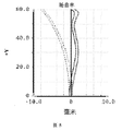
- FIG. 5 is a field curvature diagram of a 2P structure lens according to an embodiment of the present invention.
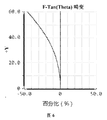
- FIG. 6 is a distortion diagram of a 2P structure lens according to an embodiment of the present invention.
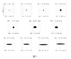
- FIG. 7 is a dot-column diagram of a 2P structure lens according to an embodiment of the present invention.
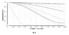
- FIG. 8 is a chromatic aberration diagram of a 2P structure lens according to an embodiment of the present invention.
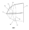
- FIG. 9 is a schematic diagram of a receiver of a 2P structure lens deviating from the optical axis by ⁇ 2 mm according to an embodiment of the present invention.
- Figure 10 is a schematic illustration of a 2P structured lens receiver with a 2 mm offset from the optical axis, in accordance with one embodiment of the present invention.
- One prior art of an eyepiece lens for a VR device includes: a front group and a rear group in order along the incident direction of the light, the front group including a first negative lens and a second positive lens, and the rear group including a similar cemented lens group: a third positive lens and a fourth negative lens, the first negative lens having a first surface convex toward the object side and a second surface concave toward the image side, located at the beginning of the lens, the second positive lens having a third side of the concave object side a surface and a fourth surface convex toward the image side, the third positive lens having a fifth surface convex toward the object side and a sixth surface convex toward the image side, the fourth negative lens having a seventh surface and a concave direction of the concave object side Like the eighth surface of the square.
- the design concept of the present invention is that the eyepiece lens for the existing VR device has a problem of small field of view and poor user experience, and at the same time, the structure is complicated, and the face shape of the lens module single lens is not easy to control.
- the lens can be corrected for MTF, SPOT, etc., the manufacturing cost is high, and the weight is large.
- the lens of the present invention uses two convex lenses, one of which is a plano-convex lens close to the pupil, and the other one is close to the object.
- the surface of the plano-convex lens near the lenticular lens is aspherical, and the radius of curvature R2 ⁇ 0
- both surfaces of the lenticular lens are aspherical
- the radii of curvature of the two surfaces satisfy the following relationship: R3 ⁇ - R4.
- the technical solution of the present invention can not only meet the requirement of a large angle of view VR, but also obtain a large angle of view of 120°, so that the user can obtain a better immersion feeling, and at the same time, the surface shape of the lens module single lens is easy to control. Molding, better correction of aberrations such as MTF and SPOT, lower manufacturing cost and greatly reduced weight, can improve user experience and improve product competitiveness.
- the 2P structure lens includes a first convex lens L1 and a second convex lens L2 which are sequentially disposed opposite to a light incident direction, first.
- the convex lens L1 is a plano-convex lens
- the second convex lens L2 is a lenticular lens;
- the first convex lens L1 includes a first surface S1 which is a plane close to the pupil, a pupil located at a pupil of the human eye 11, and a second surface S2 which is an aspheric surface of the convex object 12;
- the second convex lens L1 includes a third surface S3 and a fourth surface S4.
- the third surface S3 and the fourth surface S4 are both aspherical, and the third surface S3 is adjacent to the second surface S2 of the first convex lens L1 and convex toward the pupil.
- the four surface S4 is convex toward the object side 12; the radius of curvature R3 of the third surface S3 and the radius of curvature R4 of the fourth surface S4 satisfy the following relationship: R3 ⁇ - R4.
- the structure diagram of the 2P structure lens shown in FIG. 1 and the optical principle diagram of the 2P structure lens shown in FIG. 2 show that the 2P structure lens in this embodiment is set as a display and the image on the display.
- the light is emitted, incident on the lens via the fourth surface S4 of the second convex lens L2, and then the lens is emitted from the first surface S1 of the first convex lens L1 to enter the image in the human eye 11, but the position of the image seen in the human eye 11 Not at the display position, but at the intersection of the inverse extension of the light entering the human eye from the first surface S1, that is, at the position of the imaging surface 13.
- the technical solution of the embodiment can not only meet the needs of the large viewing angle VR, but also enable the user to obtain a better immersion.
- the correction of aberrations such as MTF and SPOT is better, which can improve the user experience and improve the competitiveness of the product.
- the focus of the two convex lenses of the 2P structure lens is mainly described.
- a specific implementation of the 2P structure lens is as follows:
- the focal length f1 of the first convex lens L1 and the focal length f2 of the second convex lens L2 satisfy the following relationship:
- the second convex lens L2 bears most of the power.
- the technical solution of the embodiment can make the structure of the lens more compact and reduce the overall volume of the lens, which is beneficial to the practical application and improvement of the user experience of the 2P structure lens of the present invention.
- the focal length f1 of the first convex lens L1 and the focal length f2 of the second convex lens L2 further satisfy the following relationship:
- the second convex lens L2 bears most of the optical power.
- the technical solution of the embodiment further improves the structure of the lens and reduces the overall volume of the lens.
- the processing difficulty of the lens is minimized, thereby facilitating the practical application and improvement of the user experience of the 2P structure lens of the present invention, and is beneficial to reducing the cost and improving the yield.
- the radius of curvature R3 of the third surface of the second convex lens L2 and the radius of curvature R4 of the fourth surface further satisfy the following relationship:
- the second convex lens L2 further bears more power, and at the same time, the third surface S3 and the fourth surface S4 of the second convex lens L2 are more easily processed and corrected, so that the embodiment
- the technical solution further makes the structure of the lens more compact, reduces the overall volume of the lens, reduces the processing difficulty of the lens, improves the processing quality and the yield of the lens, thereby further improving the market competitiveness of the 2P structural lens of the present invention.
- the first convex lens L1 and the second convex lens L2 are produced by using a COP (Cyclo-olefin polymer) optical plastic material and an injection molding process.
- COP Cyclo-olefin polymer
- the weight of the lens of the embodiment is greatly reduced when the COP optical plastic material is used instead of the glass material and other low-end PMMA (polymethyl methacrylate), PC (resin) or the like.
- the plastic lens of the embodiment is produced by using an injection molding process, can be mass-produced, and has stable performance and low cost.
- the cost of the 2P structure lens of the present invention can be further reduced, and the competitiveness can be improved.
- the second surface S2 of the first convex lens L1, the third surface S3 and the fourth surface S4 of the second convex lens L2 both satisfy the following even aspheric equation formula:
- the second surface S2 of the first convex lens L1 and the third surface S3 and the fourth surface S4 of the second convex lens L2 satisfy the above-described even-aspherical equation formula, and the quadratic term is up to 8th power.
- the design of this embodiment is completed by ZEMAX optical design software, and the same design ideas can also be completed using CODEC optical design software.
- the initial structure is established as shown in Figure 3.
- the evaluation function is built on the basis of the initial structure, and the design purpose is achieved by adding various operand constraints.
- the final optimization result is shown in Figure 1.
- Table 1 lists the optical surface numbers (Surface) numbered sequentially by the object side 12, and the radius of curvature (R) of each optical surface on the optical axis.
- the 2P structure lens of the embodiment can better control the aberrations of the MTF, the distortion, the SPOT, etc., improve the imaging quality, and improve the user experience.
- the second surface of the first convex lens, the third surface and the fourth surface of the second convex lens satisfy the following odd-order aspheric equation formula:
- z is the coordinate along the optical axis direction
- Y is the radial coordinate in units of lens length units
- c 1/R
- c is the curvature
- R is the radius of curvature
- k is the conic coefficient
- ⁇ i is the higher order term
- the design purpose can also be achieved by using the above-mentioned odd-order aspheric equation formula.
- the field curvature, distortion, dot map, and MTF can be sequentially referred to FIG. 5, FIG. 6, FIG. 7, and FIG. 8.
- the above figures are mainly for the reference wavelength green light (540 nm). analysis.
- the 2P structure lens of this embodiment has a field curvature of less than 10 mm, a distortion of less than 50%, and an RMS (root mean square) point of less than 0.3 mm.
- the RMS point is less than 0.45 mm.
- the 2P structure lens can meet the needs of a large angle of view VR, can obtain a large angle of view of 120°, and has good optical parameter performance.
- the head-mounted display optical system includes, in order from the incident direction of the light, a diaphragm, a 2P structure lens according to any one of Embodiments 1 to 7, and a display, the pupil being located in the human eye 11.
- Pupil display Located at object side 12.
- the head-mounted display optical system of this embodiment may further form a head-wearing device by providing a head-mounted fixing component, which may preferably be a fixed strap or a fixed helmet, etc., thereby facilitating operation and use by the user. Improve the user experience.
- a head-mounted fixing component which may preferably be a fixed strap or a fixed helmet, etc.
Landscapes
- Physics & Mathematics (AREA)
- General Physics & Mathematics (AREA)
- Optics & Photonics (AREA)
- Lenses (AREA)
Abstract
一种2P结构镜头、头戴显示光学系统及头戴设备,该2P结构镜头包括逆着光线入射方向依次设置的平凸的第一凸透镜(L1)和双凸的第二凸透镜(L2),第一凸透镜(L1)包括第一表面(S1)和第二表面(S2),第一表面(S1)为靠近光阑的平面,光阑位于人眼(11)瞳孔处;第二表面(S2)为凸向物方(12)的非球面;第一表面(S1)的曲率半径R1=0,第二表面(S2)的曲率半径R2<0;第二凸透镜(L2)包括第三表面(S3)和第四表面(S4),第三表面(S3)和第四表面(S4)均为非球面,第三表面(S3)靠近第一凸透镜(L1)的第二表面(S2)并凸向光阑,第四表面(S4)凸向物方(12);第三表面(S3)的曲率半径R3与第四表面(S4)的曲率半径R4:R3<-R4,使得镜头模组单片镜片的面型更易于控制成型,对于MTF、SPOT像差的校正更好,同时获得大视场角。
Description
本发明涉及目镜镜头技术领域,具体涉及一种2P结构镜头、头戴显示光学系统及头戴设备。
发明背景
近年来,随着科技工业的进步,3D技术得以迅速和广泛的发展,越来越多的影视和游戏都是基于VR(Vatual Reality,虚拟现实)技术的模拟真实场景,并且要求效果逼真震撼;使得头戴显示器作为一种新兴的技术,首先在娱乐领域有了很好的发展前景,其把二维平面的画面以更加立体的形象展现给用户,使得用户产生身临其境的真实感受。
现有的VR设备用的目镜镜头,多局限于小视场的成像系统,其镜头FOV(Field of View,视场)小于100°,用户使用设备观察场景时,会感觉到存在明显的边界,无法满足游戏领域一些高端用户追求VR的沉浸感的要求,而用户体验则主要取决于目镜的视场角,因此,现有的VR设备用的目镜镜头存在视场角小、用户体验不佳的问题。
发明内容
本发明提供了一种2P(2pieces,两片)结构镜头、头戴显示光学系统及头戴设备,以解决采用小视场的成像系统其镜头的视场角小、用户体验不佳的问题。
根据本发明的一个方面,提供了一种2P结构镜头,包括逆着光线入射方向依次设置的第一凸透镜和第二凸透镜,第一凸透镜为平凸透镜,第二凸透镜为双凸透镜;
第一凸透镜包括第一表面和第二表面,第一表面为靠近光阑的平面,光阑位于人眼瞳孔处;第二表面为凸向物方的非球面;第一表面的曲率半径R1与第二表面的曲率半径R2分别满足以下关系式:R1=0,R2<0;
第二凸透镜包括第三表面和第四表面,第三表面和第四表面均为非球面,第三表面靠近第一凸透镜的第二表面并凸向光阑,第四表面凸向物方;第三表面的曲率半径R3与第四表面的曲率半径R4满足以下关系式:R3<-R4。
根据本发明的另一个方面,提供了一种头戴显示光学系统,该头戴显示光学系统逆着光线入射方向依次包括:光阑、如本发明的一个方面的2P结构镜头,以及显示器,光阑位于人眼瞳孔处,显示器位于物方。
根据本发明的又一个方面,提供了一种头戴设备,包如本发明的另一个方面的头戴显
示光学系统。
本发明的有益效果是:本发明的这种2P结构镜头,首先,整组镜头包括两片透镜,其中一片为非球面的平凸透镜,另一片为非球面的双凸透镜,且平凸透镜上第一表面的曲率半径R1与第二表面的曲率半径R2分别满足以下关系式:R1=0,R2<0,双凸透镜上第三表面的曲率半径R3与第四表面的曲率半径R4满足以下关系式:R3<-R4,该2P结构使得镜头模组单片镜片的面型更易于控制成型,对于MTF(Modulation Transfer Function,调制传递函数)、SPOT(光斑)等像差的校正更好,同时能够获得120°的大视场角,能够作为高性能版本的头戴显示器目镜;其次,其制造成本和重量都大大降低。
另外,本发明还提供了一种头戴显示光学系统及头戴设备,其不仅可以满足大视场角VR的需要,更能够使得用户获得更好的沉浸感,从而提供较佳的用户体验,提高产品的竞争力。
附图简要说明
图1是本发明一个实施例的一种2P结构镜头的结构示意图;
图2是本发明一个实施例的一种2P结构镜头的工作状态光学原理图;
图3是本发明一个实施例的一种2P结构镜头的初始结构示意图;
图4是本发明一个实施例的一种2P结构镜头的接收者偏离光轴0mm时的光学结构图;
图5是本发明一个实施例的一种2P结构镜头的场曲图;
图6是本发明一个实施例的一种2P结构镜头的畸变图;
图7是本发明一个实施例的一种2P结构镜头的点列图;
图8是本发明一个实施例的一种2P结构镜头的色差图;
图9是本发明一个实施例的一种2P结构镜头的接收者偏离光轴-2mm时的示意图;
图10是本发明一个实施例的一种2P结构镜头的接收者偏离光轴2mm时的示意图。
VR设备用的目镜镜头的一种现有技术是:沿着光线入射方向依次包括:前组和后组,前组包括第一负透镜和第二正透镜,后组包括一个类似胶合透镜组:第三正透镜和第四负透镜,第一负透镜具有凸向物方的第一表面和凹向像方的第二表面,位于镜头的始端,第二正透镜具有凹向物方的第三表面和凸向像方的第四表面,第三正透镜具有凸向物方的第五表面和凸向像方的第六表面,第四负透镜具有凹向物方的第七表面和凹向像方的第八表面。但是,这种技术多局限于小视场的成像系统,其镜头FOV较小,用户使用设备观察
场景时,会感觉到存在明显的边界,无法满足游戏领域一些高端用户追求VR的沉浸感的要求,而用户体验则主要取决于目镜的视场角,因此,现有的VR设备用的目镜镜头存在视场角小、用户体验不佳的问题,同时,还存在结构复杂,镜头模组单片镜片的面型不易于控制成型,无法实现对MTF、SPOT等像差的校正,制造成本高,以及重量较大的问题。
本发明的设计构思是:针对现有的VR设备用的目镜镜头存在视场角小、用户体验不佳的问题,同时,还存在结构复杂,镜头模组单片镜片的面型不易于控制成型,无法实现对MTF、SPOT等像差的校正,制造成本高,以及重量较大的问题,本发明的镜头采用两片凸透镜,其中一片凸透镜是靠近光阑的平凸透镜,另外一片凸透镜是靠近物方的双凸透镜;平凸透镜靠近光阑的表面是平面,其曲率半径R1=0,平凸透镜靠近双凸透镜的表面是非球面,其曲率半径R2<0;双凸透镜的两个表面均为非球面,其两个表面的曲率半径分别满足以下关系式:R3<-R4。这样,本发明的技术方案不仅可以满足大视场角VR的需要,能获得120°大视场角,使得用户能够获得更好的沉浸感,同时使得镜头模组单片镜片的面型易于控制成型,对MTF、SPOT等像差的校正更好,制造成本更低,重量大大减小,能够改善用户体验,提高产品的竞争力。
实施例一
图1是本发明一个实施例的一种2P结构镜头的工作状态光学原理图,参见图1,该2P结构镜头包括逆着光线入射方向依次设置的第一凸透镜L1和第二凸透镜L2,第一凸透镜L1为平凸透镜,第二凸透镜L2为双凸透镜;
第一凸透镜L1包括第一表面S1和第二表面S2,第一表面S1为靠近光阑的平面,光阑位于人眼11的瞳孔处;第二表面S2为凸向物方12的非球面;第一表面S1的曲率半径R1与第二表面S2的曲率半径R2分别满足以下关系式:R1=0,R2<0;
第二凸透镜L1包括第三表面S3和第四表面S4,第三表面S3和第四表面S4均为非球面,第三表面S3靠近第一凸透镜L1的第二表面S2并凸向光阑,第四表面S4凸向物方12;第三表面S3的曲率半径R3与第四表面S4的曲率半径R4满足以下关系式:R3<-R4。
由图1所示的2P结构镜头的结构示意图,及图2所示的2P结构镜头的工作状态光学原理图可知,本实施例中的2P结构镜头,物方12设置为显示器,显示器上的影像发出光线,经由第二凸透镜L2的第四表面S4射入镜头,然后由第一凸透镜L1的第一表面S1射出镜头,进入人眼11中成像,但在人眼11中看到的影像的位置不在显示器位置处,而是在从第一表面S1进入人眼的光线的反向延长线的交点处,即成像面13位置处。这样,本实施例的技术方案不仅可以满足大视场角VR的需要,使得用户能够获得更好的沉浸感,
同时对MTF、SPOT等像差的校正更好,能够改善用户体验,提高产品的竞争力。
实施例二
本实施例中是重点对2P结构镜头的两片凸透镜的焦距进行的说明,其他内容参见本发明的其他实施例。该2P结构镜头的一种具体实现方式如下:
第一凸透镜L1的焦距f1和第二凸透镜L2的焦距f2满足以下关系式:
f2>10×f1。
需要说明的是,本实施例中,第二凸透镜L2承担了大部分的光焦度。这样,本实施例的技术方案能够使得镜头的结构更加紧凑,减小镜头的整体体积,有利于本发明的2P结构镜头的现实推广应用和提升用户体验。
实施例三
本实施例中是重点对2P结构镜头的第二凸透镜L2的焦距的进一步说明,其他内容参见本发明的其他实施例。该2P结构镜头的一种具体实现方式如下:
第一凸透镜L1的焦距f1和第二凸透镜L2的焦距f2还进一步满足以下关系式:
100mm<f2<150mm,12mm<f1<14mm。
需要说明的是,本实施例中,第二凸透镜L2承担了大部分的光焦度,这样,本实施例的技术方案在尽量进一步使得镜头的结构更加紧凑,减小镜头的整体体积的基础上,又尽量降低镜片的加工难度,从而更有利于本发明的2P结构镜头的现实推广应用和提升用户体验,又有利于降低成本,且提高成品率。
实施例四
本实施例中是重点对2P结构镜头的第二凸透镜L2的两个非球面表面的曲率半径的进一步说明,其他内容参见本发明的其他实施例。该2P结构镜头的一种具体实现方式如下:
第二凸透镜L2的第三表面的曲率半径R3与第四表面的曲率半径R4进一步满足以下关系式:
R3>0,R4<0,-200mm<R3<-R4<200mm。
需要说明的是,本实施例中,第二凸透镜L2进一步承担更多的光焦度,同时使得第二凸透镜L2的第三表面S3和第四表面S4更加易于加工和补正,这样,本实施例的技术方案在进一步使得镜头的结构更加紧凑,减小镜头的整体体积,同时降低镜片的加工难度,提高镜片的加工质量和成品率,从而更加有利于提高本发明的2P结构镜头的市场竞争能力。
实施例五
本实施例中是重点对2P结构镜头的两片凸透镜的材料和工艺的进一步说明,其他内容参见本发明的其他实施例。该2P结构镜头的一种具体实现方式如下:
第一凸透镜L1和第二凸透镜L2采用COP(Cyclo—olefin polymer)光学塑料材质和注塑工艺生产制成。
需要说明的是,本实施例中,使用COP光学塑料材质相比使用玻璃材质和其他低端PMMA(聚甲基丙烯酸甲酯)、PC(树脂)等材质,使得本实施例的镜头重量大幅下降,并且本实施例的塑料镜片通过采用注塑工艺生产,能够进行大批量生产,且性能稳定,成本较低。这样,能够进一步降低本发明的2P结构镜头的成本,提高竞争力。
实施例六
本实施例中是重点对2P结构镜头的两片凸透镜的各个表面的进一步说明,其他内容参见本发明的其他实施例。该2P结构镜头的一种具体实现方式如下:
第一凸透镜L1的第二表面S2、第二凸透镜L2的第三表面S3和第四表面S4均满足以下偶次非球面方程公式:

[根据细则91更正 20.03.2017]
其中,z为沿光轴方向的坐标,Y为以透镜长度单位为单位的径向坐标,c=1/R,c为曲率,R为曲率半径,k为圆锥系数(Coin Constant),αi为各高次项的系数,2i为非球面的高次方(the order of Aspherical Coefficient),i=4。
其中,z为沿光轴方向的坐标,Y为以透镜长度单位为单位的径向坐标,c=1/R,c为曲率,R为曲率半径,k为圆锥系数(Coin Constant),αi为各高次项的系数,2i为非球面的高次方(the order of Aspherical Coefficient),i=4。
需要说明的是,本实施例中,第一凸透镜L1的第二表面S2、第二凸透镜L2的第三表面S3和第四表面S4均满足上述偶次非球面方程公式,且二次项最高到8次方。
本实施例的设计方案通过ZEMAX光学设计软件来完成,同样的设计思路也可以使用CODEV光学设计软件完成。首先,先建立初始结构如图3所示,然后在初始结构的基础上建立评价函数,通过添加各种操作数约束来达到设计目的,最终优化的结果如图1所示。
本实施例的设计结果如表一所示,表一中分别列有由物方12开始,依序编号的光学表面序号(Surface),在光轴上各光学面的曲率半径(R),从物方12到像方的成像面13的光轴上各面与后一光学表面的距离(T),如图4中所示,T即表示第二凸透镜L2的第四表面S4到后一面(物方12)的距离,圆锥系数(Coin Constant)k,以及非球面系数α1、α2、α3、α4。
表一
| surface | R | T | k | α1 | α2 | α3 | α4 |
| L1-S1 | Infinity | 12.6762 | 0.00 | 0.00 | 0.00 | 0.00 | 0.00 |
| L1-S2 | -30.3098 | 1.9943 | -6.88E-01 | 0.00 | 2.12E-06 | -3.41E-09 | -1.15E-12 |
| L2-S1 | 111.2277 | 12.2932 | 3.33E+00 | 0.00 | 9.34E-07 | -5.11E-10 | -1.90E-13 |
| L2-S2 | -199.2492 | 31.3000 | 2.33E+01 | 0.00 | 0.00E+00 | 0.00E+00 | 0.00E+00 |
以上可见,本实施例的2P结构镜头能够更好的控制MTF、畸变、SPOT等项像差,提高成像质量,提升用户体验。
实施例七
本实施例中是重点对2P结构镜头的两片凸透镜的各个表面的另一种进一步说明,其他内容参见本发明的其他实施例。该2P结构镜头的一种具体实现方式如下:
第一凸透镜的第二表面、第二凸透镜的第三表面和第四表面满足以下奇次非球面方程公式:

[根据细则91更正 20.03.2017]
其中,z为沿光轴方向的坐标,Y为以透镜长度单位为单位的径向坐标,c=1/R,c为曲率,R为曲率半径,k为圆锥系数,βi为各高次项的系数,i为非球面的高次方;i=2N+1,N为自然数,1≤N≤8。
其中,z为沿光轴方向的坐标,Y为以透镜长度单位为单位的径向坐标,c=1/R,c为曲率,R为曲率半径,k为圆锥系数,βi为各高次项的系数,i为非球面的高次方;i=2N+1,N为自然数,1≤N≤8。
需要说明的是,利用上述奇次非球面方程公式同样也能够达到设计目的。本实施例的2P结构镜头,其场曲、畸变、点列图、MTF可依次参见图5、图6、图7和图8所示,上述各图中主要针对参考波长绿光(540nm)进行分析。
以上可见,本实施例的2P结构镜头,其场曲在10mm以内,畸变在50%以内,RMS(均方根)点小于0.3mm。如图9和图10分别所示,在光阑处的人眼11作为接收者,分别偏离光轴-2mm和2mm时,RMS点小于0.45mm。该2P结构镜头,能够满足大视场角VR的需要,能获得120°大视场角,且具有良好的光学参数性能。
实施例八
参见图2,该头戴显示光学系统,逆着光线入射方向依次包括:光阑、如实施例一至实施例七中任一项所述的2P结构镜头,以及显示器,光阑位于人眼11的瞳孔处,显示器
位于物方12。
需要说明的是,该实施例的头戴显示光学系统还可以通过设置头戴固定部件形成头戴设备,头戴固定部件可以优选为固定带或固定头盔等,从而方便使用者的操作和使用,提升用户使用体验感觉。
以上所述仅为本发明的较佳实施例而已,并非用于限定本发明的保护范围。凡在本发明的精神和原则之内所作的任何修改、等同替换、改进等,均包含在本发明的保护范围内。
Claims (9)
- 一种2P结构镜头,包括逆着光线入射方向依次设置的第一凸透镜和第二凸透镜,其特征在于,所述第一凸透镜为平凸透镜,所述第二凸透镜为双凸透镜;所述第一凸透镜包括第一表面和第二表面,所述第一表面为靠近光阑的平面,所述光阑位于人眼瞳孔处;所述第二表面为凸向物方的非球面;所述第一表面的曲率半径R1与所述第二表面的曲率半径R2分别满足以下关系式:R1=0,R2<0;所述第二凸透镜包括第三表面和第四表面,所述第三表面和所述第四表面均为非球面,所述第三表面靠近所述第一凸透镜的所述第二表面并凸向光阑,所述第四表面凸向物方;所述第三表面的曲率半径R3与所述第四表面的曲率半径R4满足以下关系式:R3<-R4。
- 如权利要求1所述的2P结构镜头,其特征在于,所述第一凸透镜的焦距f1和所述第二凸透镜的焦距f2满足以下关系式:f2>10×f1。
- 如权利要求2所述的2P结构镜头,其特征在于,所述第一凸透镜的焦距f1和所述第二凸透镜的焦距f2还进一步满足以下关系式:100mm<f2<150mm,12mm<f1<14mm。
- 如权利要求1所述的2P结构镜头,其特征在于,所述第三表面的曲率半径R3与所述第四表面的曲率半径R4进一步满足以下关系式:R3>0,R4<0,-200mm<R3<-R4<200mm。
- 如权利要求1所述的2P结构镜头,其特征在于,所述第一凸透镜和所述第二凸透镜采用COP光学塑料材质和注塑工艺生产制成。
- [根据细则91更正 20.03.2017]
如权利要求1-5中任一项所述的2P结构镜头,其特征在于,所述第一凸透镜的所述第二表面、所述第二凸透镜的所述第三表面和所述第四表面均满足以下偶次非球面方程公式:

其中,z为沿光轴方向的坐标,Y为以透镜长度单位为单位的径向坐标,c=1/R,c为曲率,R为曲率半径,k为圆锥系数,αi为各高次项的系数,2i为非球面的高次方,i=4。 - [根据细则91更正 20.03.2017]
如权利要求1-5中任一项所述的2P结构镜头,其特征在于,所述第一凸透镜的所述第二表面、所述第二凸透镜的所述第三表面和所述第四表面满足以下奇次非球面方程公式:

其中,z为沿光轴方向的坐标,Y为以透镜长度单位为单位的径向坐标,c=1/R,c为曲率,R为曲率半径,k为圆锥系数,βi为各高次项的系数,i为非球面的高次方;i=2N+1,N为自然数,1≤N≤8。 - 一种头戴显示光学系统,其特征在于,该头戴显示光学系统逆着光线入射方向依次包括:光阑、如权利要求1至7中任一项所述的2P结构镜头,以及显示器,所述光阑位于人眼瞳孔处,所述显示器位于物方。
- 一种头戴设备,其特征在于,包括权利要求8所述的头戴显示光学系统。
Applications Claiming Priority (2)
| Application Number | Priority Date | Filing Date | Title |
|---|---|---|---|
| CN201611064600.X | 2016-11-28 | ||
| CN201611064600.XA CN106773010B (zh) | 2016-11-28 | 2016-11-28 | 一种2p结构镜头、头戴显示光学系统及头戴设备 |
Publications (1)
| Publication Number | Publication Date |
|---|---|
| WO2018094851A1 true WO2018094851A1 (zh) | 2018-05-31 |
Family
ID=58901995
Family Applications (1)
| Application Number | Title | Priority Date | Filing Date |
|---|---|---|---|
| PCT/CN2016/114047 Ceased WO2018094851A1 (zh) | 2016-11-28 | 2016-12-31 | 一种2p结构镜头、头戴显示光学系统及头戴设备 |
Country Status (2)
| Country | Link |
|---|---|
| CN (1) | CN106773010B (zh) |
| WO (1) | WO2018094851A1 (zh) |
Cited By (6)
| Publication number | Priority date | Publication date | Assignee | Title |
|---|---|---|---|---|
| CN110262038A (zh) * | 2019-06-06 | 2019-09-20 | 歌尔股份有限公司 | 光学系统及具有其的虚拟现实设备 |
| CN114839767A (zh) * | 2022-03-31 | 2022-08-02 | 歌尔光学科技有限公司 | 低畸变光学成像调整方法、系统以及头戴显示设备 |
| CN116679451A (zh) * | 2023-06-01 | 2023-09-01 | 上海摩软通讯技术有限公司 | 一种双通镜头及虚拟现实头戴显示器 |
| CN117310981A (zh) * | 2022-06-22 | 2023-12-29 | 北京字跳网络技术有限公司 | 光学系统以及显示装置 |
| WO2024138975A1 (zh) * | 2022-12-29 | 2024-07-04 | 上海视涯技术有限公司 | 近眼显示设备和近眼显示光学模组 |
| US12352934B2 (en) | 2022-04-29 | 2025-07-08 | Largan Precision Co., Ltd. | Projection lens system, projection apparatus and electronic device |
Families Citing this family (4)
| Publication number | Priority date | Publication date | Assignee | Title |
|---|---|---|---|---|
| CN108828752B (zh) * | 2018-06-12 | 2022-01-11 | 戴雅贝森(苏州)科技有限公司 | 一种复合透镜及光谱仪 |
| CN111385444A (zh) * | 2018-12-28 | 2020-07-07 | 武汉华星光电半导体显示技术有限公司 | 一种摄像模组及其所在的显示模组和终端器件 |
| CN111999889B (zh) | 2019-05-11 | 2025-04-01 | 京东方科技集团股份有限公司 | 曲面透镜和显示装置 |
| CN119644601B (zh) * | 2024-12-30 | 2025-11-25 | 歌尔光学科技有限公司 | 光学系统及智能头戴设备 |
Citations (6)
| Publication number | Priority date | Publication date | Assignee | Title |
|---|---|---|---|---|
| US5786935A (en) * | 1993-10-27 | 1998-07-28 | Asahi Kogaku Kogyo Kabushiki Kaisha | Scope |
| US6057968A (en) * | 1996-10-11 | 2000-05-02 | Olympus Optical Co., Ltd. | Eyepiece system |
| CN1460191A (zh) * | 2001-02-14 | 2003-12-03 | 索尼公司 | 透镜、组合透镜及其制造方法、光学拾波装置及光盘装置 |
| CN2795884Y (zh) * | 2003-11-21 | 2006-07-12 | 中国科学院长春光学精密机械与物理研究所 | 微型显示目镜光学成像装置 |
| CN104503076A (zh) * | 2014-11-28 | 2015-04-08 | 青岛歌尔声学科技有限公司 | 一种微显示目镜和头戴设备 |
| CN206282028U (zh) * | 2016-11-28 | 2017-06-27 | 歌尔科技有限公司 | 一种2p结构镜头、头戴显示光学系统及头戴设备 |
Family Cites Families (10)
| Publication number | Priority date | Publication date | Assignee | Title |
|---|---|---|---|---|
| US3768890A (en) * | 1971-06-12 | 1973-10-30 | Nippon Kogaku Kk | Internal focusing wide angle eyepiece |
| US5764418A (en) * | 1995-04-17 | 1998-06-09 | Olympus Optical Co., Ltd. | Eyepiece system |
| JPH1138330A (ja) * | 1997-05-21 | 1999-02-12 | Asahi Optical Co Ltd | 接眼レンズ |
| JP2003005059A (ja) * | 2001-06-27 | 2003-01-08 | Minolta Co Ltd | 光ピックアップ用対物レンズ |
| GB0207630D0 (en) * | 2002-04-02 | 2002-05-15 | Meyer Paul A R | Viewing device |
| KR101661655B1 (ko) * | 2009-06-30 | 2016-09-30 | 엘지이노텍 주식회사 | 카메라 렌즈 모듈 |
| JP6003503B2 (ja) * | 2012-10-04 | 2016-10-05 | 株式会社ニコン | 接眼光学系、光学機器 |
| JP6036549B2 (ja) * | 2013-05-23 | 2016-11-30 | ソニー株式会社 | 接眼レンズおよび表示装置 |
| CN103837968B (zh) * | 2014-03-19 | 2017-05-03 | 青岛歌尔声学科技有限公司 | 头戴显示设备用镜头及头戴显示设备 |
| CN204116696U (zh) * | 2014-06-28 | 2015-01-21 | 青岛歌尔声学科技有限公司 | 一种无色差的头戴设备用广角内调焦镜头及头戴设备 |
-
2016
- 2016-11-28 CN CN201611064600.XA patent/CN106773010B/zh active Active
- 2016-12-31 WO PCT/CN2016/114047 patent/WO2018094851A1/zh not_active Ceased
Patent Citations (6)
| Publication number | Priority date | Publication date | Assignee | Title |
|---|---|---|---|---|
| US5786935A (en) * | 1993-10-27 | 1998-07-28 | Asahi Kogaku Kogyo Kabushiki Kaisha | Scope |
| US6057968A (en) * | 1996-10-11 | 2000-05-02 | Olympus Optical Co., Ltd. | Eyepiece system |
| CN1460191A (zh) * | 2001-02-14 | 2003-12-03 | 索尼公司 | 透镜、组合透镜及其制造方法、光学拾波装置及光盘装置 |
| CN2795884Y (zh) * | 2003-11-21 | 2006-07-12 | 中国科学院长春光学精密机械与物理研究所 | 微型显示目镜光学成像装置 |
| CN104503076A (zh) * | 2014-11-28 | 2015-04-08 | 青岛歌尔声学科技有限公司 | 一种微显示目镜和头戴设备 |
| CN206282028U (zh) * | 2016-11-28 | 2017-06-27 | 歌尔科技有限公司 | 一种2p结构镜头、头戴显示光学系统及头戴设备 |
Cited By (6)
| Publication number | Priority date | Publication date | Assignee | Title |
|---|---|---|---|---|
| CN110262038A (zh) * | 2019-06-06 | 2019-09-20 | 歌尔股份有限公司 | 光学系统及具有其的虚拟现实设备 |
| CN114839767A (zh) * | 2022-03-31 | 2022-08-02 | 歌尔光学科技有限公司 | 低畸变光学成像调整方法、系统以及头戴显示设备 |
| US12352934B2 (en) | 2022-04-29 | 2025-07-08 | Largan Precision Co., Ltd. | Projection lens system, projection apparatus and electronic device |
| CN117310981A (zh) * | 2022-06-22 | 2023-12-29 | 北京字跳网络技术有限公司 | 光学系统以及显示装置 |
| WO2024138975A1 (zh) * | 2022-12-29 | 2024-07-04 | 上海视涯技术有限公司 | 近眼显示设备和近眼显示光学模组 |
| CN116679451A (zh) * | 2023-06-01 | 2023-09-01 | 上海摩软通讯技术有限公司 | 一种双通镜头及虚拟现实头戴显示器 |
Also Published As
| Publication number | Publication date |
|---|---|
| CN106773010B (zh) | 2023-09-15 |
| CN106773010A (zh) | 2017-05-31 |
Similar Documents
| Publication | Publication Date | Title |
|---|---|---|
| CN106773010B (zh) | 一种2p结构镜头、头戴显示光学系统及头戴设备 | |
| TWI510806B (zh) | 光學拾像系統組 | |
| TWI440883B (zh) | 結像鏡頭 | |
| CN107490840B (zh) | 取像用光学镜组、取像装置及电子装置 | |
| CN106886081B (zh) | 取像用光学镜头组、取像装置及电子装置 | |
| CN107402430B (zh) | 光学影像镜头、取像装置及电子装置 | |
| CN103713381B (zh) | 结像系统镜头组 | |
| CN103424844B (zh) | 光学取像系统镜组 | |
| TW201403120A (zh) | 光學結像鏡片系統、取像裝置及可攜裝置 | |
| TW201200900A (en) | Wide-viewing-angle imaging lens assembly | |
| TWI725283B (zh) | 電子裝置 | |
| CN108873269B (zh) | 摄像镜头组及取像装置 | |
| CN106199926B (zh) | 光学镜头 | |
| CN104142565A (zh) | 近红外交互式投影镜头 | |
| CN207663138U (zh) | 光学成像镜头 | |
| CN109085694A (zh) | 五片式广角镜片组 | |
| CN202583579U (zh) | 成像系统镜组 | |
| CN109557635B (zh) | 光学镜头 | |
| CN109212716B (zh) | 四片式红外单波长镜片组 | |
| CN108227190A (zh) | 一种镜头模组 | |
| CN106773009A (zh) | 目镜光学系统 | |
| CN110068909A (zh) | 四片式红外单波长投影镜片组 | |
| CN204009209U (zh) | 近红外交互式投影镜头 | |
| CN106501928A (zh) | 一种光学系统 | |
| CN206282028U (zh) | 一种2p结构镜头、头戴显示光学系统及头戴设备 |
Legal Events
| Date | Code | Title | Description |
|---|---|---|---|
| 121 | Ep: the epo has been informed by wipo that ep was designated in this application |
Ref document number: 16922448 Country of ref document: EP Kind code of ref document: A1 |
|
| NENP | Non-entry into the national phase |
Ref country code: DE |
|
| 122 | Ep: pct application non-entry in european phase |
Ref document number: 16922448 Country of ref document: EP Kind code of ref document: A1 |