WO2018092237A1 - プログラムコード生成装置、プログラムコード生成方法及びプログラムコード生成プログラム - Google Patents
プログラムコード生成装置、プログラムコード生成方法及びプログラムコード生成プログラム Download PDFInfo
- Publication number
- WO2018092237A1 WO2018092237A1 PCT/JP2016/084077 JP2016084077W WO2018092237A1 WO 2018092237 A1 WO2018092237 A1 WO 2018092237A1 JP 2016084077 W JP2016084077 W JP 2016084077W WO 2018092237 A1 WO2018092237 A1 WO 2018092237A1
- Authority
- WO
- WIPO (PCT)
- Prior art keywords
- block
- block diagram
- program code
- code generation
- processing procedure
- Prior art date
- Legal status (The legal status is an assumption and is not a legal conclusion. Google has not performed a legal analysis and makes no representation as to the accuracy of the status listed.)
- Ceased
Links
Images






Classifications
-
- G—PHYSICS
- G06—COMPUTING OR CALCULATING; COUNTING
- G06F—ELECTRIC DIGITAL DATA PROCESSING
- G06F8/00—Arrangements for software engineering
- G06F8/40—Transformation of program code
- G06F8/41—Compilation
- G06F8/43—Checking; Contextual analysis
- G06F8/433—Dependency analysis; Data or control flow analysis
-
- G—PHYSICS
- G06—COMPUTING OR CALCULATING; COUNTING
- G06F—ELECTRIC DIGITAL DATA PROCESSING
- G06F11/00—Error detection; Error correction; Monitoring
- G06F11/36—Prevention of errors by analysis, debugging or testing of software
-
- G—PHYSICS
- G06—COMPUTING OR CALCULATING; COUNTING
- G06F—ELECTRIC DIGITAL DATA PROCESSING
- G06F11/00—Error detection; Error correction; Monitoring
- G06F11/36—Prevention of errors by analysis, debugging or testing of software
- G06F11/3604—Analysis of software for verifying properties of programs
-
- G—PHYSICS
- G06—COMPUTING OR CALCULATING; COUNTING
- G06F—ELECTRIC DIGITAL DATA PROCESSING
- G06F8/00—Arrangements for software engineering
- G06F8/30—Creation or generation of source code
- G06F8/34—Graphical or visual programming
-
- G—PHYSICS
- G06—COMPUTING OR CALCULATING; COUNTING
- G06F—ELECTRIC DIGITAL DATA PROCESSING
- G06F8/00—Arrangements for software engineering
- G06F8/40—Transformation of program code
- G06F8/41—Compilation
-
- G—PHYSICS
- G06—COMPUTING OR CALCULATING; COUNTING
- G06F—ELECTRIC DIGITAL DATA PROCESSING
- G06F9/00—Arrangements for program control, e.g. control units
- G06F9/06—Arrangements for program control, e.g. control units using stored programs, i.e. using an internal store of processing equipment to receive or retain programs
- G06F9/44—Arrangements for executing specific programs
-
- G—PHYSICS
- G06—COMPUTING OR CALCULATING; COUNTING
- G06F—ELECTRIC DIGITAL DATA PROCESSING
- G06F9/00—Arrangements for program control, e.g. control units
- G06F9/06—Arrangements for program control, e.g. control units using stored programs, i.e. using an internal store of processing equipment to receive or retain programs
- G06F9/44—Arrangements for executing specific programs
- G06F9/445—Program loading or initiating
-
- G—PHYSICS
- G06—COMPUTING OR CALCULATING; COUNTING
- G06F—ELECTRIC DIGITAL DATA PROCESSING
- G06F9/00—Arrangements for program control, e.g. control units
- G06F9/06—Arrangements for program control, e.g. control units using stored programs, i.e. using an internal store of processing equipment to receive or retain programs
- G06F9/44—Arrangements for executing specific programs
- G06F9/445—Program loading or initiating
- G06F9/44568—Immediately runnable code
- G06F9/44578—Preparing or optimising for loading
-
- G—PHYSICS
- G06—COMPUTING OR CALCULATING; COUNTING
- G06F—ELECTRIC DIGITAL DATA PROCESSING
- G06F11/00—Error detection; Error correction; Monitoring
- G06F11/30—Monitoring
- G06F11/3003—Monitoring arrangements specially adapted to the computing system or computing system component being monitored
- G06F11/302—Monitoring arrangements specially adapted to the computing system or computing system component being monitored where the computing system component is a software system
-
- G—PHYSICS
- G06—COMPUTING OR CALCULATING; COUNTING
- G06F—ELECTRIC DIGITAL DATA PROCESSING
- G06F11/00—Error detection; Error correction; Monitoring
- G06F11/30—Monitoring
- G06F11/32—Monitoring with visual or acoustical indication of the functioning of the machine
- G06F11/323—Visualisation of programs or trace data
Definitions
- the present invention relates to a program code generation device, a program code generation method, and a program code generation program.
- the block diagram includes a plurality of blocks and connection lines connecting the blocks.
- Each block defines data processing procedure elements. Specifically, a group of data processing is defined for each block.
- connection lines By connecting a plurality of blocks with connection lines, the flow of the data processing procedure from when the program acquires the input value to when the output value indicating the operation result is output is described in the block diagram.
- Patent Document 1 As a technique for generating a program code from a block diagram, for example, there is a technique disclosed in Patent Document 1.
- JP 2011-13887 A Japanese Unexamined Patent Publication No. 2016-57715
- Patent Documents 1 and 2 when the generated block diagram is compared with an inappropriate block diagram pattern, the generated block diagram matches the inappropriate block diagram pattern. Notify that is inappropriate. As described above, the techniques of Patent Documents 1 and 2 have a problem that an inappropriate block diagram pattern needs to be provided in advance in order to detect an inappropriate block diagram.
- the main object of the present invention is to solve such problems. That is, the main object of the present invention is to obtain a configuration that can detect an inappropriate block diagram without providing an inappropriate block diagram pattern in advance.
- the program code generation device includes: A block diagram acquisition unit that acquires a block diagram that defines a data processing procedure to be reflected in the program code by connecting a plurality of blocks; And a contradiction checking unit for checking whether there is a contradiction in the data processing procedure defined in the block diagram by tracing the connection between the blocks in the block diagram.
- connection between the blocks in the block diagram is traced to check whether there is any inconsistency in the data processing procedure. Therefore, according to the present invention, an inappropriate block diagram can be detected without providing an inappropriate block diagram pattern in advance.
- FIG. 3 is a diagram illustrating a functional configuration example of a program code generation device according to the first embodiment.
- 5 is a flowchart showing an operation example of the program code generation device according to the first embodiment.
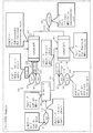
- FIG. 3 illustrates an example of a block diagram according to Embodiment 1;
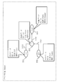
- FIG. 4 shows an example of SubA according to the first embodiment.
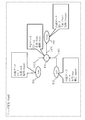
- FIG. 3 shows an example of SubB according to the first embodiment.
- FIG. 6 is a diagram illustrating an example of an analysis rule according to the first embodiment.
- FIG. 4 is a diagram illustrating an example of an inspection rule according to the first embodiment.
- FIG. 4 is a diagram illustrating an example of a code generation rule according to the first embodiment.
- FIG. 4 is a diagram illustrating an example of a code generation rule according to the first embodiment.
- FIG. 4 is a diagram illustrating an example of a code generation rule according to the first embodiment.
- FIG. 4 is a diagram illustrating an example of a code generation rule according to the first embodiment.
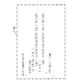
- FIG. 3 is a diagram illustrating an example of a program code according to the first embodiment.
- FIG. 3 is a diagram illustrating an example of a program code according to the first embodiment.
- FIG. 6 shows an example of violation information according to the first embodiment.
- 5 is a flowchart showing an operation example of an inspection object extraction unit according to the first embodiment.
- 5 is a flowchart showing an operation example of a block diagram inspection unit according to the first embodiment.
- 5 is a flowchart illustrating an operation example of a program code generation unit according to the first embodiment.
- FIG. 3 is a diagram illustrating a hardware configuration example of the program code generation device according to the first embodiment.
- FIG. *** Explanation of configuration *** FIG. 1 shows a functional configuration example of a program code generation device 1 according to the present embodiment.
- FIG. 16 shows a hardware configuration example of the program code generation device 1 according to the present embodiment.
- a hardware configuration example of the program code generation device 1 will be described with reference to FIG. 16, and then a functional configuration example of the program code generation device 1 will be described with reference to FIG.
- the operations performed in the program code generation device 1 correspond to a program code generation method and a program code generation program.
- the program code generation device 1 is a computer.
- the program code generation device 1 includes a processor 1901, an auxiliary storage device 1902, a main storage device 1903, a communication device 1904, and an input / output device 1905 as hardware.
- the auxiliary storage device 1902 stores programs that realize the functions of the block diagram acquisition unit 11, the inspection object extraction unit 14, the block diagram inspection unit 15, and the program code generation unit 17 illustrated in FIG. 1. Then, these programs are loaded from the auxiliary storage device 1902 to the main storage device 1903, and the processor 1901 executes these programs, and a block diagram acquisition unit 11, an inspection object extraction unit 14, a block diagram inspection unit 15 and a program code to be described later. The operation of the generation unit 17 is performed.
- the auxiliary storage device 1902 implements the block diagram analysis rule storage unit 12, the inspection rule storage unit 13, and the code generation rule storage unit 16 shown in FIG. Note that at least one of the block diagram analysis rule storage unit 12, the inspection rule storage unit 13, and the code generation rule storage unit 16 may be realized by the main storage device 1903.
- the communication device 1904 is used when the program code generation device 1 communicates with an external device. If the program code generation device 1 does not communicate with an external device, the communication device 1904 may be omitted.
- the input / output device 1905 acquires an instruction from the user of the program code generation device 1, a block diagram 2 and the like. Further, the input / output device 1905 presents the program code 3 or the violation information 4 to the program code generation device 1.
- the block diagram acquisition unit 11 acquires the block diagram 2 via the input / output device 1905.
- the block diagram 2 is data that defines a data processing procedure to be reflected in the program code by connecting a plurality of blocks. That is, the block diagram 2 mainly includes a plurality of blocks and connection lines that connect the blocks. Note that a processing procedure element that is an element of a data processing procedure is assigned to each of the plurality of blocks in the block diagram 2.
- the processing procedure element is a group of data processing.
- the block diagram acquisition unit 11 can acquire a plurality of block diagrams 2. The operation performed by the block diagram acquisition unit 11 corresponds to block diagram acquisition processing.
- the block diagram analysis rule storage unit 12 stores analysis rules.
- the analysis rule is used when the inspection object extraction unit 14 analyzes the structure of the block diagram.
- the block diagram analysis rule storage unit 12 holds the analysis rule.
- the block diagram 2 may include the analysis rule.
- the inspection rule storage unit 13 stores inspection rules.
- the inspection rule is used when the block diagram inspection unit 15 inspects whether there is a contradiction in the data processing procedure defined in the block diagram 2.
- the inspection rule storage unit 13 may store a plurality of inspection rules.
- the inspection object extraction unit 14 traces connections between blocks in the block diagram 2 based on the analysis rule and the inspection rule, and extracts blocks and connection lines to be inspected from the block diagram 2. More specifically, the inspection object extraction unit 14 sets one of a plurality of blocks as a starting block, and the inspection object extraction unit 14 connects the blocks in the block diagram in FIG. 2 from the starting block. , And the block on which the starting block depends is extracted as a dependent block. Further, the inspection object extraction unit 14 repeats the operation of extracting the block on which the extracted dependence destination block depends as the dependence destination block, and extracts the dependence destination block on which the starting block depends directly and indirectly. .
- the block diagram inspection unit 15 applies an inspection rule to the blocks and connection lines extracted by the inspection object extraction unit 14 to inspect whether there is any inconsistency in the data processing procedure defined in the block diagram 2. To do. That is, the block diagram inspecting unit 15 inspects whether there is any part in the block diagram 2 that violates the inspection rule. For example, the block diagram inspection unit 15 has a contradiction in at least one of the data type, the maximum value, and the minimum value between the process procedure element assigned to the starting block and the process procedure element assigned to the dependence destination block. Check for the presence. Further, when there is a contradiction in the data processing procedure defined in the block diagram 2, the block diagram inspection unit 15 outputs violation information 4 for notifying the contradiction in the data processing procedure via the input / output device 1905.
- the inspection object extraction unit 14 and the block diagram inspection unit 15 are collectively referred to as a contradiction inspection unit 18. That is, the inspection object extraction unit 14 and the block diagram inspection unit 15 follow the connection between the blocks in the block diagram 2 as the contradiction inspection unit 18 and check whether there is a contradiction in the data processing procedure defined in the block diagram 2. Inspect whether.
- the operation performed by the contradiction inspection unit 18 corresponds to a contradiction inspection process.
- the code generation rule storage unit 16 stores code generation rules.
- the code generation rule is used when the program code generation unit 17 generates the program code 3 from the block diagram 2.
- the program code generation unit 17 generates the program code 3 from the block diagram 2 based on the code generation rule. That is, when there is no contradiction in the data processing procedure defined in the block diagram 2, the program code generation unit 17 generates a program code reflecting the data processing procedure defined in the block diagram 2 from the block diagram 2. Generate.
- the program code is written in a computer language.
- the block diagram acquisition unit 11 acquires the block diagram 2 via the input / output device 1905 (step S1).
- the inspection object extraction unit 14 applies the analysis rules stored in the block diagram analysis rule storage unit 12 and the inspection rules stored in the inspection rule storage unit 13 to the block diagram 2, and the block diagram 2.
- the information to be examined is extracted from (step S2). Details of step S2 will be described later.
- step S3 the block diagram inspection unit 15 applies the inspection rules stored in the inspection rule storage unit 13 to the information about the inspection target extracted by the inspection target extraction unit 14 and is defined in the block diagram 2.
- the data processing procedure is inspected for consistency (step S3). Details of step S3 will be described later.
- step S4 If there is no contradiction in the data processing procedure defined in the block diagram 2 as a result of the inspection in step S3 (YES in step S4), the program code generation unit 17 stores the code generation rule storage unit 16 in the block diagram 2 in FIG.
- the program code 3 is generated by applying the stored code generation rule (step S5). Details of step S5 will be described later.
- step S4 when there is a contradiction in the data processing procedure defined in the block diagram 2 (NO in step S4), the block diagram inspection unit 15 sends the violation information 4 for notifying the contradiction in the data processing procedure from the input / output device 1905. Output (step S6).
- the format of violation information 4 will be described later.
- the program code generation device 1 checks whether the block diagram 2 is appropriate, and generates the program code 3 if the block diagram 2 is appropriate.
- block diagram 2 analysis rule stored in block diagram analysis rule storage unit 12, inspection rule stored in inspection rule storage unit 13, code generation rule stored in code generation rule storage unit 16, Details of the program code 3 and the violation information 4 will be described.
- Block diagram 2 is not only information that represents only the appearance of block diagrams such as image files, but also information necessary for drawing programs as block diagrams on development tools, and additions for simulation and automatic code generation This file contains typical information.
- the block diagram 2 is realized as a file including data capable of expressing a hierarchical data structure such as XML (Extensible Markup Language) and JSON (JavaScript (registered trademark) Object Notification).
- XML Extensible Markup Language
- JSON JavaScript (registered trademark) Object Notification
- the block diagram 2 is expressed not in the XML or JSON format but in a format in which a plurality of blocks are connected by connection lines.
- the additional information is expressed by a balloon or the like as necessary.
- FIG. 3 to 5 show an example of the block diagram 2.
- FIG. FIG. 3 shows a block diagram 2 in which a data processing procedure to be reflected in the program code is defined.
- FIG. 4 shows details of SubA, which is a subroutine included in the block diagram 2 of FIG.
- FIG. 5 shows details of SubB, which is a subroutine included in the block diagram 2 of FIG.
- elements to which reference numerals B1 to B9 are attached are blocks.
- elements denoted by reference numerals L12, L23, L24, L53, L63, L74, L84, and L349 are connection lines.
- elements denoted by reference numerals B31 to B34 are blocks.
- elements denoted by reference numerals L313, L323, and L334 are connection lines.
- elements denoted by reference numerals B41 to B44 are blocks.
- elements denoted by reference numerals L413, L423, and L434 are connection lines.
- the internal data includes, for example, a block ID (Identifier), a block name, and a block type.
- the contents included in the internal data set in each block are processing procedure elements.
- the ID of the block B1 is 1, the name of the block B1 is In1, and the type of the block B1 is Input.
- the ID is a number or a character string for uniquely identifying each block. In this embodiment, the ID is a unique number.
- the name is arbitrarily given so that the user of the program code generation device 1 can easily identify each block when the block diagram 2 is displayed on the display.
- the block type is used to identify the data processing characteristics assigned to each block.
- the type of block includes input, output, addition, if branch, subsystem, and the like.
- a plurality of numbers and character strings are defined in advance as identifiers representing block types.
- “Input” is set as the type in the block B1, and input processing is assigned as a processing procedure element to the block B1.
- a block to which input processing is assigned is referred to as an input block.
- “Output” is set as the type in the block B9, and output processing is assigned as a processing procedure element to the block B9.
- a block to which output processing is assigned is referred to as an output block.
- a block to which an addition operation process is assigned as a process procedure element (a block whose type is “Sum”) is referred to as a Sum block. Note that the Sum block is not shown in FIG.
- a block to which an if branch process is assigned as a processing procedure element (a block whose type is “If”) is referred to as an “if block”.
- a block to which a subsystem is assigned as a processing procedure element (a block whose type is “Subsystem”) is referred to as a Subsystem block.
- the internal data also includes attribute information necessary for finally generating the program code 3 from the block diagram 2.
- the internal data of the input block includes, as attribute information, the data type of the input data, the maximum value or / and the minimum value of the input data.
- the internal data includes, as attribute information, information on conditions for performing the control and information on a processing destination when the conditions are met.
- connection line is a line connecting two arbitrary blocks.
- the connection line is a directed line for indicating the flow of processing and data.
- IDs of two blocks to which the connection line is connected and information regarding the processing or data flow direction are set as internal data.
- the internal data of the connection line includes the ID of the connection source block and the ID of the connection destination block. Further, when there are a plurality of output ports in the connection source block, or when there are a plurality of input ports in the connection destination block, the internal data of the connection line includes the ID of the block port.
- the internal data of the connection line L12 describes “connection source: 1 # out: 1” and “connection destination: 2 # in: 1”.
- connection line L12 connects the output port 1 of the block B1 and the input port 1 of the block B2.
- the block diagram inspecting unit 15 since the internal data of the connection line describes the ID of the connection source block and the ID of the connection destination block, the block diagram inspecting unit 15 also specifies the data flow and processing flow between the blocks. can do. For example, the block diagram inspecting unit 15 can specify that the data output from the input block B1 is input to the If block B2 by referring to the internal data of the connection line L12. As described above, the block diagram inspecting unit 15 can identify the connection relationship between the blocks in the block diagram 2 by referring to the internal data of the connection lines included in the block diagram 2.
- the block diagram checking unit 15 analyzes the connection relationship between blocks and the data processing assigned to each block, and checks whether there is a contradiction in the data processing procedure defined in the block diagram 2. Since the connection line can be identified by the ID of the connection source block and the ID of the connection destination block, no ID is set for the connection line in this embodiment. An ID may be set for the connection line.
- FIG. 6 shows an example of the analysis rule.
- the analysis rule 600 of FIG. 6 information obtained from a block is defined for each block type.
- the analysis rule 600 of FIG. 6 includes a type 601, a data input number 602, a data output number 603, a control input number 604, a control output number 605, and an attribute 606.
- a type 601 represents a block type.
- the data input number 602 represents the number of data input to the block. When “1 or more” is described in the number of data inputs 602, the number of data input to the block is variable.
- the data output number 603 represents the number of data output from the block.
- the number of control inputs 604 represents the number of inputs related to process control. For example, in the Subsystem 614, the number of control inputs 604 is defined as “1 or more”.
- a control output 605 represents the number of outputs related to control of processing. For example, In 613, the control output number 605 is defined as “2”. This means that two control results in the If block are output.
- An attribute 606 indicates an attribute supported by the block.
- FIG. 6 shows the analysis rule 600 described in a natural language for the sake of simplifying the explanation, the analysis rule 600 may be described in a program language.
- FIG. 7 shows an example of the inspection rule.
- the inspection rule 700 in FIG. 7 describes a rule for detecting a contradiction in the data processing procedure defined in the block diagram 2.
- the inspection rule 700 in FIG. 7 includes an object 701, a starting point 702, an end point 703, and an inspection item 704.
- An object 701 represents the type of inspection object.
- Block 711 represents an inspection item for each block.
- DataSlice 712 represents an inspection item for the data slice.
- Slice 713 represents an inspection item for a slice.
- the data slice refers to a slice extracted considering only the data dependency without considering the control dependency.
- the execution result of data processing assigned to a certain block (referred to as block ⁇ ) affects the execution of data processing assigned to another block (referred to as block ⁇ ).
- the block ⁇ has a “control dependency” with the block ⁇ .
- Block ⁇ is a dependency block of block ⁇ .
- the block B3 has a control dependency relationship with the block B2. That is, the block B2 is a dependency block of the block B3.
- the “data dependency” means that data output from a certain block (referred to as block ⁇ ) reaches another block (referred to as block ⁇ ). For example, in FIG.
- a “slice” is a set of blocks having a control dependency and data dependency with a certain block (and their connection relationship). In other words, a slice follows a set of blocks (and their connection relationships) obtained from a block following a block having a control dependency relationship with the block, and a block having a data dependency relationship with the block. It is a set of blocks obtained (and their connection relations). In other words, a slice is a set of all blocks related to the block (and its connection relationship).
- the “slice extracted by considering only the data dependency without considering the control dependency” is a slice that can be constructed without the control dependency. That is, a data slice is a set of blocks (and their connection relations) obtained by tracing only a block having a data dependency relationship with the block from a certain block.
- the starting point 702 represents the type of block that is the starting point when searching for control dependency or data dependency.
- “Output” is described as the starting point 702 for DataSlice 712 and Slice 713. Therefore, the block diagram inspecting unit 15 obtains a data slice from a block having the type “Output” by tracing a block having a data dependency with the block having the type “Output”. Further, the block diagram inspection unit 15 obtains a slice by tracing a block having a data dependency relationship and a control dependency relationship with a block having the type “Output” from the block having the type “Output”.
- the end point 703 represents the type of block for which the search for the control dependency or the data dependency is finished.
- the block diagram checking unit 15 continues to search for the control dependency or the data dependency until the control dependency or the data dependency cannot be searched, that is, until the input block is reached.
- the search of the block diagram inspection unit 15 is completed up to a specific type of block, the type corresponding to the column of the end point 703 is defined. For example, when acquiring a slice from the output block to the If block, “If” is set as the end point 703.
- the inspection item 704 indicates the inspection content for the extracted inspection object.
- the block diagram checking unit 15 determines that there is a contradiction in the data processing procedure described in the block diagram 2.
- the block diagram inspecting unit 15 performs the data processing described in the block diagram 2 when the DataType of any block included in the path of the data slice is different from the DataType of the starting block. Judge that the procedure is inconsistent.
- the inspection rule 700 described in a natural language is shown for the sake of simplicity, but the inspection rule 700 may be described in a program language.
- code generation rules Next, the code generation rules stored in the code generation rule storage unit 16 will be described. 8 and 9 show examples of code generation rules.
- the code generation rules 800 and 900 in FIGS. 8 and 9 describe information necessary for generating the program code 3 based on the information included in the block diagram 2.
- a code generation rule 800 is a general code generation rule that is not related to the expression of the block diagram 2.
- the code generation rule 900 is a code generation rule related to the expression of block diagram 2.
- a pair of a general item 801 relating to a program code and its conversion rule 802 is described.
- the code generation rule 800 for example, for the item “function name”, it is described in the conversion rule 802 that the file name in the block diagram excluding the extension is used.
- the code generation rule 900 of FIG. 9 a pair of a block type 901 indicating the type of each block and its conversion rule 902 is described.
- the code generation rule 900 as a conversion rule for a block whose block type 611 is “Input”, the language type is a member of the IN structure, the member name is the value of the name attribute, and the data type is the type attribute. Is described as the value of.
- the program code generation unit 17 Based on such code generation rules 800 and 900, the program code generation unit 17 generates the program code 3 from the block diagram 2.
- code generation rules 800 and 900 show the code generation rules 800 and 900 described in a natural language for the sake of simplicity of explanation, the code generation rules 800 and 900 may be described in a program language.
- the program code shown in FIG. 10 is called program code 1000, and the program code shown in FIG. 11 is called program code 1100.
- the program code 1000 is a header file, and the program code 1100 is a source file. Both program code 1000 and program code 1100 are written in C language.
- an IN structure that handles all inputs is defined (reference numeral 1001 in FIG. 10).
- an OUT structure representing an output is also defined (reference numeral 1002 in FIG. 10).
- a prototype declaration of the function “sample” is also defined (reference numeral 1003 in FIG. 10).
- the program code 1100 the code generated from the block diagram 2 is described.
- FIG. 12 shows an example of the violation information 4.
- the violation information 4 includes information for notifying the contradiction in the data processing procedure, that is, the location in the block diagram 2 where the violation has occurred.
- the violation information 4 includes an inspection rule 1201, a violation block 1202, a related slice 1203, and a related path 1204.
- the inspection rule 1201 indicates the number of the inspection rule 700 used when a violation is detected when there are a plurality of inspection rules 700.
- the violation block 1202 indicates the ID of the block including the violation. In the related slice 1203, when a violation is detected in the inspection of the slice 713 included in the inspection rule 700, an ID of a block included in the slice in which the violation is detected is listed.
- the related path 1204 indicates a path included in the slice when a violation is detected in the inspection of the slice 713 included in the inspection rule 700.
- a number surrounded by one ⁇ means one path.
- the violation information 4 may be displayed as a list of no violations and violations for each inspection item 704 of the inspection rule 700, unlike the format shown in FIG. For example, “YES” may be displayed for the inspection item 704 without violation, and “NO” may be displayed for the inspection item 704 with violation. Further, in order to notify the violation content in a manner that is easier for the user of the program code generation device 1 to understand, an explanatory note explaining the violation content may be added to the violation information 4.
- step S2 will be described with reference to FIG.
- the inspection object extraction unit 14 acquires the block diagram 2 from the block diagram acquisition unit 11 (step S21).
- the inspection object extraction unit 14 reads the analysis rule from the block diagram analysis rule storage unit 12 (step S22).
- the inspection object extraction unit 14 reads the inspection rule from the inspection rule storage unit 13 (step S23).
- the inspection object extraction unit 14 extracts the inspection object from the block diagram 2 using the inspection rule read in step S23 (step S24).
- the inspection object extraction unit 14 performs step S24 for each inspection rule.
- the inspection object extraction unit 14 operates as follows, for example.
- the inspection object extraction unit 14 extracts all blocks as inspection objects. However, the inspection object extraction unit 14 does not analyze the relationship between blocks.
- the inspection target extraction unit 14 since the starting point 703 is “Output” and the end point 704 is “arbitrary”, the inspection target extraction unit 14 considers only the data dependency, starting from the block whose block type is “Output”. And extract slices. That is, the inspection object extraction unit 14 extracts a set of blocks that affect data handled in data processing assigned to a block whose block type is “Output”. For example, the inspection object extraction unit 14 extracts the block B3 and the block B4 as blocks having a data dependency relationship with the block B9 in FIG. That is, the block B3 and the block B4 are dependent blocks of the block B9.
- the inspection object extraction unit 14 extracts the block B3 and the block B4 with reference to the analysis rule of FIG. First, the inspection object extraction unit 14 refers to the row 612 in which the type 601 is “Output” in FIG. 6. Next, the inspection object extraction unit 14 refers to the data input number 602 in the row 612. In FIG. 6, since it is “1 or more”, the block whose type is “Output” is affected by the output data from other blocks. For this reason, the block connected to the block of type “Output” by the connection line has a data dependency relationship with the block of type “Output”. Therefore, in FIG. 3, the block B3 and the block B4 connected to the block B9 through the connection line are extracted as blocks having a data dependency relationship with the block B9. That is, the block B3 and the block B4 are dependent blocks of the block B9.
- the inspection object extraction unit 14 checks whether there is a data dependency relationship between each of the block B3 and the block B4. Since the type of the block B3 is Subsystem, the inspection object extraction unit 14 refers to the row 614 in FIG. In the row 614, since the data input number 602 is “1 or more”, it can be seen that the block B3 has a data dependency relationship with the block in which data is input to the block B3. However, in the case of the Subsystem, since the entity is in another block diagram, it is necessary to check another block diagram. In the case of the block B3, the substance is shown in SubA of FIG. The inspection object extraction unit 14 performs the same analysis on FIG. Since the block B34 in FIG. 4 and the block B9 in FIG.
- the block B34 is connected to the block B33.
- the type of the block B33 is “Sum”.
- the data output number 603 is “1”.
- the block B33 has a data dependency relationship with the block B34. That is, the block B33 is a dependency block of the block B34 (block B9).
- the block B33 is connected to the block B31 and the block B32.
- the type of each of the block B31 and the block B32 is “Input”, and the data output number 603 is “1” in the row 611 of the analysis rule 600 in FIG. For this reason, the block B31 and the block B32 have a data dependency relationship with the block B33.
- the block B31 and the block B32 are dependent blocks of the block B33.
- the inspection object extraction unit 14 returns to FIG. 3 and continues the analysis.
- the type of the block B2 is “If”, and the data output number 603 is “0” in the row 613 of the analysis rule 600 in FIG. For this reason, the block B3 has no data dependency with the block B2. That is, the block B2 is not a dependency block of the block B3.
- the type of each of the block B5 and the block B6 is “Input”, and the data output number 603 is “1” in the row 611 of the analysis rule 600 in FIG. For this reason, the block B5 and the block B6 have a data dependency relationship with the block B3. That is, the block B5 and the block B6 are dependent blocks of the block B3. Since In2 in FIG.
- the inspection object extraction unit 14 merges the extraction results.
- the inspection object extraction unit 14 also analyzes the data dependency relationship in the same procedure for the block B4, which is the other dependent block of the block B9 in FIG.
- the inspection object extraction unit 14 converts the block B9, the block B3, the block B5, the block B6, the block B7, the block B8, the block B33 in FIG. 4, and the block B43 in FIG. 5 as the data slice of the block B9 in FIG. Extract. Note that the set of block B9, block B3, block B5, block B6, block B33 and the set of block B9, block B4, block B7, block B8 and block B43 in FIG.
- the extraction unit 14 manages each as a separate path.
- the inspection target extraction unit 14 extracts slices from the block whose type is “Output” according to the slice 713 of the inspection rule 700 of FIG.
- the inspection object extraction unit 14 extracts a block in consideration of the control dependency in addition to the data dependency.
- a control dependency on a block is a set of block outputs that affect the execution of the block.
- the block having a control dependency relationship with the block B3 and the block B4 in FIG. 3 is the block B2 in FIG. 3 that is an If block.
- the inspection object extraction unit 14 adds the block B2 and the block B1 in FIG. 3 to the set of blocks extracted as the data slices described above to obtain the inspection object slice.
- the inspection object extraction unit 14 can extract the inspection target block, the inspection object slice, and the inspection object data slice.
- step S3 in FIG. 2 will be described with reference to FIG.
- the block diagram inspection unit 15 marks all inspection rules as uninspected (step S41).
- the block diagram inspection unit 15 confirms whether or not there is an uninspected inspection rule (step S42).
- the block diagram inspection unit 15 reads one uninspected inspection rule from the inspection rule storage unit 13 (step S43).
- the block diagram inspection unit 15 inspects the block diagram 2 according to the read inspection rule (step S44). Specifically, the block diagram inspection unit 15 applies the inspection rule to the blocks, data slices, and slices extracted by the inspection object extraction unit 14 and performs the data processing procedure defined in the block diagram 2. Check for inconsistencies. That is, the block diagram inspection unit 15 inspects whether there is a block for which DataType is not set in all the blocks extracted by the inspection object extraction unit 14 according to the row 711 of the inspection rule 700 in FIG. Further, the block diagram inspecting unit 15 includes a block of DataType that is different from the DataType of the starting block for each data slice path extracted by the inspection object extracting unit 14 in accordance with the row 712 of the inspection rule 700 in FIG. 7. Check for any. Further, the block diagram inspection unit 15 inspects whether Min or Max differs between the paths of the slices extracted by the inspection object extraction unit 14 according to the row 713 of the inspection rule 700 in FIG.
- the block diagram inspection unit 15 confirms whether or not an inspection rule violation has been detected (step S45).
- the block diagram inspection unit 15 When an inspection rule violation is detected (YES in step S45), the block diagram inspection unit 15 temporarily stores details of the inspection rule violation in the main storage device 1903 or the like as violation detection information (step S46). For example, the block diagram inspection unit 15 uses the ID of the inspection rule in which the violation is detected, the ID of the block in which the violation is detected, the slice in which the violation is detected, the path in which the violation is detected, etc. as the main memory. 1903 or the like. Thereafter, the block diagram inspection unit 15 marks the inspection rule that has been inspected as inspected (step S47), and returns to step S42.
- step S45 When the processing for one inspection rule is completed without detecting a violation (NO in step S45), the block diagram inspection unit 15 marks the inspection rule that has been inspected as inspected (step S47), The process returns to step S42.
- step S42 If it is determined in step S42 that there are no uninspected inspection rules (NO in step S42), the block diagram inspection unit 15 checks whether violation detection information exists in the main storage device 1903 or the like (step S42). S48).
- step S48 If there is violation detection information (YES in step S48), the block diagram inspection unit 15 outputs the violation detection information as violation information 4 to the display of the input / output device 905, and ends the process. If the violation detection information does not exist (NO in step S48), the block diagram inspection unit 15 instructs the program code generation unit 17 to generate a program code.
- step S5 in FIG. 2 will be described with reference to FIG.
- the program code generation unit 17 reads a code generation rule from the code generation rule storage unit 16 (step S51).
- the program code generation unit 17 acquires the block diagram 2 from the block diagram inspection unit 15 (step S52).
- the program code generation unit 17 generates the program code 3 from the block diagram 2 using the code generation rule (step S53).
- step S53 for example, if the read code generation rules are the code generation rule 800 in FIG. 8 and the code generation rule 900 in FIG. 9, the program code generation unit 17 follows the code generation rule 800 and the header file and the source Generate a file.
- the file name of the header file is obtained by adding “.h” to the file name of the block diagram 2
- the file name of the source file is obtained by adding “.c” to the file name of the block diagram 2. Therefore, if the file name in the block diagram 2 is “sample.blk”, the program code generation unit 17 generates files “sample.h” and “sample.c”. At this time, the function name of the function included in “sample.c” is “sample”.
- the program code generation unit 17 defines the input data structure and the output data structure of the header file “sample.h”.
- the program code generation unit 17 generates a structure of input data (IN structure) based on internal data of a block whose block type is “Input”. Further, the program code generation unit 17 generates the output data structure (OUT structure) based on the internal data of the block whose block type is “Output”.
- the program code generation unit 17 generates, for example, the program code 1000 (header file) shown in FIG. 10 from the block diagrams of FIGS. Further, the program code generation unit 17 generates the inside of the source file “sample.c” according to the code generation rule 900 of FIG.
- the program code generation unit 17 generates, for example, the program code 1100 (source file) shown in FIG. 11 from the block diagrams of FIGS.
- Embodiment 2 the data dependency relationship and the control dependency relationship in the block diagram 2 are extracted, and it is inspected whether there is a contradiction in the data processing procedure based on the inspection rule.
- the block diagram inspection unit 15 is defined in the block diagram 2 with reference to the code generation rules 800 and 900 that the program code generation unit 17 refers to in order to generate the program code 3 from the block diagram 2. Check for conflicts in data processing procedures.
- the functional configuration example of the program code generation device 1 is as shown in FIG.
- An example of the hardware configuration of the program code generation device 1 is as shown in FIG.
- the operation of the program code generation device 1 is the same as that of the first embodiment except that the block diagram inspection unit 15 refers to the code generation rules 800 and 900 in addition to the inspection rule 700.
- the present embodiment it is possible to detect a defect depending on the language specification of the program code to be generated before generating the program code. For this reason, according to the present embodiment, it is not necessary to inspect the generated program code using a static code analysis tool corresponding to the program language, and the labor of the developer can be saved.
- the block diagram 2 is input from the outside via the block diagram acquisition unit 11.
- the block diagram 2 may be generated in the program code generation device 1.
- the block diagram acquisition unit 11 of FIG. 1 generates a block diagram instead of the input of the block diagram 2 from the outside. That is, in this embodiment, the block diagram acquisition unit 11 acquires a block diagram by generating a block diagram.
- An example of the hardware configuration of the program code generation device 1 is as shown in FIG.
- the block diagram acquisition part 11 produces
- the other operations are the same as those shown in the first embodiment.
- a processor 1901 illustrated in FIG. 16 is an IC (Integrated Circuit) that performs processing.
- the processor 1901 is a CPU (Central Processing Unit), a DSP (Digital Signal Processor), or the like.
- the auxiliary storage device 1902 is a ROM (Read Only Memory), a flash memory, an HDD (Hard Disk Drive), or the like.
- the main storage device 1903 is a RAM (Random Access Memory).
- the communication device 1904 includes a receiver that receives data and a transmitter that transmits data.
- the communication device 1904 is, for example, a communication chip or a NIC (Network Interface Card).
- the input / output device 1905 is, for example, a mouse, a keyboard, a display, or the like.
- the auxiliary storage device 1902 also stores an OS (Operating System). Then, at least a part of the OS is loaded into the main storage device 1903 and executed by the processor 1901.
- the processor 1901 executes a program that realizes the functions of the block diagram acquisition unit 11, the inspection target extraction unit 14, the block diagram inspection unit 15, and the program code generation unit 17 while executing at least a part of the OS.
- the program code generation device 1 may include a plurality of processors that replace the processor 1901. The plurality of processors share the execution of programs that realize the functions of the block diagram acquisition unit 11, the inspection object extraction unit 14, the block diagram inspection unit 15, and the program code generation unit 17.
- Each processor is an IC that performs processing similar to the processor 1901.
- information, data, signal values, and variable values indicating processing results of the block diagram acquisition unit 11, the inspection target extraction unit 14, the block diagram inspection unit 15, and the program code generation unit 17 are stored in the storage device 1902 and the processor 1901. Stored in at least one of a register and a cache memory.
- the programs for realizing the functions of the block diagram acquisition unit 11, the inspection object extraction unit 14, the block diagram inspection unit 15 and the program code generation unit 17 are a magnetic disk, a flexible disk, an optical disk, a compact disk, and a Blu-ray (registered trademark) disk. Or a portable storage medium such as a DVD.
- the “part” of the block diagram acquisition unit 11, the inspection object extraction unit 14, the block diagram inspection unit 15 and the program code generation unit 17 may be read as “circuit” or “process” or “procedure” or “processing”. Good.
- the program code generation device 1 may be realized by an electronic circuit such as a logic IC (Integrated Circuit), a GA (Gate Array), an ASIC (Application Specific Integrated Circuit), or an FPGA (Field-Programmable Gate Array).
- the block diagram acquisition unit 11, the inspection object extraction unit 14, the block diagram inspection unit 15, and the program code generation unit 17 are each realized as part of an electronic circuit.
- the processor and the electronic circuit are also collectively referred to as a processing circuit.
- 1 program code generator 2 block diagram, 3 program code, 4 violation information, 11 block diagram acquisition unit, 12 block diagram analysis rule storage unit, 13 inspection rule storage unit, 14 inspection object extraction unit, 15 block diagram inspection unit, 16 code generation rule storage unit, 17 program code generation unit, 18 contradiction inspection unit, 600 analysis rule, 700 inspection rule, 800 code generation rule, 900 code generation rule, 1000 program code, 1100 program code.
Landscapes
- Engineering & Computer Science (AREA)
- Software Systems (AREA)
- Theoretical Computer Science (AREA)
- General Engineering & Computer Science (AREA)
- Physics & Mathematics (AREA)
- General Physics & Mathematics (AREA)
- Computer Hardware Design (AREA)
- Quality & Reliability (AREA)
- Debugging And Monitoring (AREA)
- Stored Programmes (AREA)
Abstract
ブロック図取得部(11)は、プログラムコードに反映させるデータ処理手順を複数のブロックの接続により定義するブロック図(2)を取得する。矛盾検査部(18)は、ブロック図(2)でのブロック間の接続を辿って、ブロック図(2)で定義されているデータ処理手順に矛盾があるかどうかを検査する。
Description
本発明は、プログラムコード生成装置、プログラムコード生成方法及びプログラムコード生成プログラムに関する。
事前に生成したプログラム仕様に基づいて、ソースコード等のプログラムコードを自動生成する方法がある。例えば、ブロック図からプログラムコードを生成する方法がある。ブロック図は、複数のブロックと、ブロック間を接続する接続線とで構成される。各ブロックには、データ処理手順の要素が定義されている。具体的には、各ブロックには、ひとまとまりのデータ処理が定義されている。接続線で複数のブロックを接続することで、ブロック図において、プログラムが入力値を取得してから演算結果が示される出力値を出力するまでのデータ処理手順の流れが記述される。
ブロック図からプログラムコードを生成する技術として、例えば、特許文献1に開示の技術がある。
ブロック図からプログラムコードを生成する技術として、例えば、特許文献1に開示の技術がある。
特許文献1及び2では、生成されたブロック図と、不適切なブロック図のパターンとを比較し、生成されたブロック図が不適切なブロック図のパターンと一致する場合に、生成されたブロック図が不適切であることを通知する。
このように、特許文献1及び2の技術では、不適切なブロック図を検出するために、不適切なブロック図のパターンを予め設けておく必要があるという課題がある。
このように、特許文献1及び2の技術では、不適切なブロック図を検出するために、不適切なブロック図のパターンを予め設けておく必要があるという課題がある。
本発明は、このような課題を解決することを主な目的とする。つまり、本発明は、不適切なブロック図のパターンを予め設けておくことなく、不適切なブロック図を検出できる構成を得ることを主な目的とする。
本発明に係るプログラムコード生成装置は、
プログラムコードに反映させるデータ処理手順を複数のブロックの接続により定義するブロック図を取得するブロック図取得部と、
前記ブロック図でのブロック間の接続を辿って、前記ブロック図で定義されているデータ処理手順に矛盾があるかどうかを検査する矛盾検査部とを有する。
プログラムコードに反映させるデータ処理手順を複数のブロックの接続により定義するブロック図を取得するブロック図取得部と、
前記ブロック図でのブロック間の接続を辿って、前記ブロック図で定義されているデータ処理手順に矛盾があるかどうかを検査する矛盾検査部とを有する。
本発明では、ブロック図でのブロック間の接続を辿ってデータ処理手順に矛盾があるかどうかを検査する。このため、本発明によれば、不適切なブロック図のパターンを予め設けておくことなく、不適切なブロック図を検出することができる。
以下、本発明の実施の形態について、図を用いて説明する。以下の実施の形態の説明及び図面において、同一の符号を付したものは、同一の部分または相当する部分を示す。
実施の形態1.
***構成の説明***
図1は、本実施の形態に係るプログラムコード生成装置1の機能構成例を示す。
また、図16は、本実施の形態に係るプログラムコード生成装置1のハードウェア構成例を示す。
先ず、図16を参照してプログラムコード生成装置1のハードウェア構成例を説明し、その後に、図1を参照してプログラムコード生成装置1の機能構成例を説明する。
なお、プログラムコード生成装置1で行われる動作は、プログラムコード生成方法及びプログラムコード生成プログラムに相当する。
***構成の説明***
図1は、本実施の形態に係るプログラムコード生成装置1の機能構成例を示す。
また、図16は、本実施の形態に係るプログラムコード生成装置1のハードウェア構成例を示す。
先ず、図16を参照してプログラムコード生成装置1のハードウェア構成例を説明し、その後に、図1を参照してプログラムコード生成装置1の機能構成例を説明する。
なお、プログラムコード生成装置1で行われる動作は、プログラムコード生成方法及びプログラムコード生成プログラムに相当する。
プログラムコード生成装置1は、コンピュータである。
プログラムコード生成装置1は、ハードウェアとして、プロセッサ1901、補助記憶装置1902、主記憶装置1903、通信装置1904及び入出力装置1905を備える。
補助記憶装置1902には、図1に示すブロック図取得部11、検査対象抽出部14、ブロック図検査部15及びプログラムコード生成部17の機能を実現するプログラムが記憶されている。
そして、これらプログラムが補助記憶装置1902から主記憶装置1903にロードされ、プロセッサ1901がこれらプログラムを実行して、後述するブロック図取得部11、検査対象抽出部14、ブロック図検査部15及びプログラムコード生成部17の動作を行う。
図1では、プロセッサ1901がブロック図取得部11、検査対象抽出部14、ブロック図検査部15及びプログラムコード生成部17の機能を実現するプログラムを実行している状態を模式的に表している。
また、補助記憶装置1902は、図1に示すブロック図解析ルール記憶部12、検査ルール記憶部13及びコード生成ルール記憶部16を実現する。なお、ブロック図解析ルール記憶部12、検査ルール記憶部13及びコード生成ルール記憶部16の少なくともいずれかが主記憶装置1903により実現されてもよい。
通信装置1904は、プログラムコード生成装置1が外部装置と通信を行う場合に用いられる。プログラムコード生成装置1が外部装置との通信を行わないのであれば、通信装置1904は省略してもよい。
入出力装置1905は、プログラムコード生成装置1のユーザからの指示、ブロック図2等を取得する。また、入出力装置1905は、プログラムコード生成装置1にプログラムコード3又は違反情報4を提示する。
プログラムコード生成装置1は、ハードウェアとして、プロセッサ1901、補助記憶装置1902、主記憶装置1903、通信装置1904及び入出力装置1905を備える。
補助記憶装置1902には、図1に示すブロック図取得部11、検査対象抽出部14、ブロック図検査部15及びプログラムコード生成部17の機能を実現するプログラムが記憶されている。
そして、これらプログラムが補助記憶装置1902から主記憶装置1903にロードされ、プロセッサ1901がこれらプログラムを実行して、後述するブロック図取得部11、検査対象抽出部14、ブロック図検査部15及びプログラムコード生成部17の動作を行う。
図1では、プロセッサ1901がブロック図取得部11、検査対象抽出部14、ブロック図検査部15及びプログラムコード生成部17の機能を実現するプログラムを実行している状態を模式的に表している。
また、補助記憶装置1902は、図1に示すブロック図解析ルール記憶部12、検査ルール記憶部13及びコード生成ルール記憶部16を実現する。なお、ブロック図解析ルール記憶部12、検査ルール記憶部13及びコード生成ルール記憶部16の少なくともいずれかが主記憶装置1903により実現されてもよい。
通信装置1904は、プログラムコード生成装置1が外部装置と通信を行う場合に用いられる。プログラムコード生成装置1が外部装置との通信を行わないのであれば、通信装置1904は省略してもよい。
入出力装置1905は、プログラムコード生成装置1のユーザからの指示、ブロック図2等を取得する。また、入出力装置1905は、プログラムコード生成装置1にプログラムコード3又は違反情報4を提示する。
次に、図1を参照して、プログラムコード生成装置1の機能構成例を説明する。
ブロック図取得部11は、入出力装置1905を介して、ブロック図2を取得する。
なお、ブロック図2とは、プログラムコードに反映させるデータ処理手順を複数のブロックの接続により定義するデータである。つまり、ブロック図2は、主に複数のブロックと各ブロックを接続する接続線から構成される。なお、ブロック図2の複数のブロックの各々にはデータ処理手順の要素である処理手順要素が割り当てられている。処理手順要素は、ひとまとまりのデータ処理である。
ブロック図取得部11は、複数のブロック図2を取得することができる。
ブロック図取得部11により行われる動作は、ブロック図取得処理に相当する。
なお、ブロック図2とは、プログラムコードに反映させるデータ処理手順を複数のブロックの接続により定義するデータである。つまり、ブロック図2は、主に複数のブロックと各ブロックを接続する接続線から構成される。なお、ブロック図2の複数のブロックの各々にはデータ処理手順の要素である処理手順要素が割り当てられている。処理手順要素は、ひとまとまりのデータ処理である。
ブロック図取得部11は、複数のブロック図2を取得することができる。
ブロック図取得部11により行われる動作は、ブロック図取得処理に相当する。
ブロック図解析ルール記憶部12は、解析ルールを記憶する。解析ルールは、検査対象抽出部14がブロック図の構造を解析する際に用いられる。
なお、本実施の形態では、ブロック図解析ルール記憶部12が解析ルールを保持することとしているが、ブロック図2に解析ルールが含まれていてもよい。
なお、本実施の形態では、ブロック図解析ルール記憶部12が解析ルールを保持することとしているが、ブロック図2に解析ルールが含まれていてもよい。
検査ルール記憶部13は、検査ルールを記憶する。検査ルールは、ブロック図検査部15がブロック図2で定義されているデータ処理手順に矛盾があるかどうかを検査する際に用いられる。
検査ルール記憶部13は、検査ルールを複数記憶してもよい。
検査ルール記憶部13は、検査ルールを複数記憶してもよい。
検査対象抽出部14は、解析ルール及び検査ルールに基づいて、ブロック図2でのブロック間の接続を辿って、ブロック図2から検査対象となるブロック及び接続線を抽出する。
より具体的には、検査対象抽出部14は、複数のブロックのうちのいずれかのブロックを起点ブロックとして設定する、そして、検査対象抽出部14は、起点ブロックからブロック図2におけるブロック間の接続を辿って、起点ブロックが依存しているブロックを依存先ブロックとして抽出する。更に、検査対象抽出部14は、抽出した依存先ブロックが依存しているブロックを依存先ブロックとして抽出する動作を繰り返し、起点ブロックが直接的及び間接的に依存している依存先ブロックを抽出する。
より具体的には、検査対象抽出部14は、複数のブロックのうちのいずれかのブロックを起点ブロックとして設定する、そして、検査対象抽出部14は、起点ブロックからブロック図2におけるブロック間の接続を辿って、起点ブロックが依存しているブロックを依存先ブロックとして抽出する。更に、検査対象抽出部14は、抽出した依存先ブロックが依存しているブロックを依存先ブロックとして抽出する動作を繰り返し、起点ブロックが直接的及び間接的に依存している依存先ブロックを抽出する。
ブロック図検査部15は、検査対象抽出部14により抽出されたブロック及び接続線に対して、検査ルールを適用して、ブロック図2で定義されているデータ処理手順に矛盾があるかどうかを検査する。つまり、ブロック図検査部15は、ブロック図2に検査ルールに違反している箇所がないかどうかを検査する。
例えば、ブロック図検査部15は、起点ブロックに割り当てられている処理手順要素と依存先ブロックに割り当てられている処理手順要素との間にデータタイプ、最大値及び最小値の少なくともいずれかにおいて矛盾があるかどうかを検査する。
また、ブロック図検査部15は、ブロック図2で定義されているデータ処理手順に矛盾がある場合に、データ処理手順における矛盾を通知する違反情報4を入出力装置1905を介して出力する。
例えば、ブロック図検査部15は、起点ブロックに割り当てられている処理手順要素と依存先ブロックに割り当てられている処理手順要素との間にデータタイプ、最大値及び最小値の少なくともいずれかにおいて矛盾があるかどうかを検査する。
また、ブロック図検査部15は、ブロック図2で定義されているデータ処理手順に矛盾がある場合に、データ処理手順における矛盾を通知する違反情報4を入出力装置1905を介して出力する。
検査対象抽出部14とブロック図検査部15をまとめて矛盾検査部18という。
つまり、検査対象抽出部14及びブロック図検査部15は、矛盾検査部18として、ブロック図2でのブロック間の接続を辿って、ブロック図2で定義されているデータ処理手順に矛盾があるかどうかを検査する。なお、矛盾検査部18により行われる動作は、矛盾検査処理に相当する。
つまり、検査対象抽出部14及びブロック図検査部15は、矛盾検査部18として、ブロック図2でのブロック間の接続を辿って、ブロック図2で定義されているデータ処理手順に矛盾があるかどうかを検査する。なお、矛盾検査部18により行われる動作は、矛盾検査処理に相当する。
コード生成ルール記憶部16は、コード生成ルールを記憶する。コード生成ルールは、プログラムコード生成部17がブロック図2からプログラムコード3を生成する際に用いられる。
プログラムコード生成部17は、コード生成ルールに基づき、ブロック図2からプログラムコード3を生成する。
つまり、プログラムコード生成部17は、ブロック図2で定義されているデータ処理手順に矛盾がない場合に、ブロック図2から、ブロック図2で定義されているデータ処理手順が反映されたプログラムコードを生成する。プログラムコードは、コンピュータ言語で記述されている。
つまり、プログラムコード生成部17は、ブロック図2で定義されているデータ処理手順に矛盾がない場合に、ブロック図2から、ブロック図2で定義されているデータ処理手順が反映されたプログラムコードを生成する。プログラムコードは、コンピュータ言語で記述されている。
***動作の説明***
次に、図2のフローチャートを参照して、プログラムコード生成装置1の動作例を説明する。
次に、図2のフローチャートを参照して、プログラムコード生成装置1の動作例を説明する。
先ず、ブロック図取得部11が、入出力装置1905を介して、ブロック図2を取得する(ステップS1)。
次に、検査対象抽出部14が、ブロック図2に、ブロック図解析ルール記憶部12に記憶されている解析ルール、検査ルール記憶部13に記憶されている検査ルールを適用して、ブロック図2から検査対象の情報を抽出する(ステップS2)。なお、ステップS2の詳細は後述する。
次に、ブロック図検査部15が、検査対象抽出部14により抽出された検査対象に関する情報に、検査ルール記憶部13に記憶されている検査ルールを適用して、ブロック図2で定義されているデータ処理手順に矛盾がないかどうかの検査を行う(ステップS3)。なお、ステップS3の詳細は後述する。
ステップS3の検査の結果、ブロック図2で定義されているデータ処理手順に矛盾がない場合(ステップS4でYES)は、プラグラムコード生成部17が、ブロック図2に、コード生成ルール記憶部16に記憶されているコード生成ルールを適用して、プログラムコード3を生成する(ステップS5)。なお、ステップS5の詳細は後述する。
一方、ブロック図2で定義されているデータ処理手順に矛盾がある場合(ステップS4でNO)は、ブロック図検査部15は、データ処理手順における矛盾を通知する違反情報4を入出力装置1905から出力する(ステップS6)。なお、違反情報4の形式については後述する。
このように、本実施の形態では、プログラムコード生成装置1は、ブロック図2が適切であるか否かを検査し、ブロック図2が適切であればプログラムコード3を生成する。
次に、ブロック図2、ブロック図解析ルール記憶部12で記憶されている解析ルール、検査ルール記憶部13で記憶されている検査ルール、コード生成ルール記憶部16で記憶されているコード生成ルール、プログラムコード3及び違反情報4の詳細を説明する。
(ブロック図の例)
ブロック図2は、画像ファイル等のブロック図の外観のみを表す情報のみではなく、開発ツール上でプログラムをブロック図として描画するために必要となる情報や、シミュレーションやコード自動生成を行うための付加的な情報が含まれているファイルである。ブロック図2は、例えば、XML(Extensible Markup Language)やJSON(JavaScript(登録商標) Object Notation)等の階層的なデータ構造を表現可能なデータを含むファイルとして実現される。ただし、以降では、理解を容易にするために、ブロック図2は、XMLやJSONの形式ではなく、複数のブロックが接続線で接続された形式で表現する。そして、必要に応じて吹き出し等で付加情報を表す。
ブロック図2は、画像ファイル等のブロック図の外観のみを表す情報のみではなく、開発ツール上でプログラムをブロック図として描画するために必要となる情報や、シミュレーションやコード自動生成を行うための付加的な情報が含まれているファイルである。ブロック図2は、例えば、XML(Extensible Markup Language)やJSON(JavaScript(登録商標) Object Notation)等の階層的なデータ構造を表現可能なデータを含むファイルとして実現される。ただし、以降では、理解を容易にするために、ブロック図2は、XMLやJSONの形式ではなく、複数のブロックが接続線で接続された形式で表現する。そして、必要に応じて吹き出し等で付加情報を表す。
図3~図5は、ブロック図2の例を示す。
図3は、プログラムコードに反映させるデータ処理手順が定義されるブロック図2を示す。図4は、図3のブロック図2に含まれるサブルーチンであるSubAの詳細を示す。また、図5は、図3のブロック図2に含まれるサブルーチンであるSubBの詳細を示す。
図3は、プログラムコードに反映させるデータ処理手順が定義されるブロック図2を示す。図4は、図3のブロック図2に含まれるサブルーチンであるSubAの詳細を示す。また、図5は、図3のブロック図2に含まれるサブルーチンであるSubBの詳細を示す。
図3において、符号B1~B9が付されている要素がブロックである。また、符号L12、L23、L24、L53、L63、L74、L84、L349が付されている要素が接続線である。
また、図4において、符号B31~B34が付されている要素がブロックである。また、符号L313、L323、L334が付されている要素が接続線である。
また、図5において、符号B41~B44が付されている要素がブロックである。また、符号L413、L423、L434が付されている要素が接続線である。
以下、図3のブロック及び接続線について説明するが、以下の説明は図4及び図5のブロック及び接続線にも適用される。
また、図4において、符号B31~B34が付されている要素がブロックである。また、符号L313、L323、L334が付されている要素が接続線である。
また、図5において、符号B41~B44が付されている要素がブロックである。また、符号L413、L423、L434が付されている要素が接続線である。
以下、図3のブロック及び接続線について説明するが、以下の説明は図4及び図5のブロック及び接続線にも適用される。
各ブロックには内部データが設定されている。内部データには、例えば、ブロックのID(Identifier)、ブロックの名前、ブロックの種別が含まれる。なお、各ブロックに設定されている内部データに含まれる内容が処理手順要素である。
例えば、ブロックB1のIDは1であり、ブロックB1の名前はIn1であり、ブロックB1の種別はInputである。IDは、各ブロックをユニークに識別するための番号や文字列である。本実施の形態では、IDはユニークな番号とする。名前は、ブロック図2をディスプレイに表示した際にプログラムコード生成装置1のユーザが各ブロックを識別しやすくするために任意につけるものである。ブロックの種別は、各ブロックに割り当てられているデータ処理の特性を識別するために用いられる。例えば、ブロックの種別として、入力、出力、加算、if分岐、サブシステム等がある。ブロックの種別を表す識別子として、複数の番号や文字列が予め定義されている。
例えば、ブロックB1のIDは1であり、ブロックB1の名前はIn1であり、ブロックB1の種別はInputである。IDは、各ブロックをユニークに識別するための番号や文字列である。本実施の形態では、IDはユニークな番号とする。名前は、ブロック図2をディスプレイに表示した際にプログラムコード生成装置1のユーザが各ブロックを識別しやすくするために任意につけるものである。ブロックの種別は、各ブロックに割り当てられているデータ処理の特性を識別するために用いられる。例えば、ブロックの種別として、入力、出力、加算、if分岐、サブシステム等がある。ブロックの種別を表す識別子として、複数の番号や文字列が予め定義されている。
例えば、ブロックB1には種別として「Input」が設定されており、ブロックB1には処理手順要素として入力処理が割り当てられている。以下、入力処理が割り当てられているブロックを入力ブロックという。
また、ブロックB9には種別として「Output」が設定されており、ブロックB9には処理手順要素として出力処理が割り当てられている。以下、出力処理が割り当てられているブロックを出力ブロックという。
また、以下では、処理手順要素として加算演算処理が割り当てられているブロック(種別が「Sum」のブロック)をSumブロックという。なお、Sumブロックは図3には示されていない。
また、処理手順要素としてif分岐処理が割り当てられているブロック(種別が「If」のブロック)をifブロックという。
また、処理手順要素としてサブシステムが割り当てられているブロック(種別が「Subsystem」のブロック)をSubsystemブロックという。
また、ブロックB9には種別として「Output」が設定されており、ブロックB9には処理手順要素として出力処理が割り当てられている。以下、出力処理が割り当てられているブロックを出力ブロックという。
また、以下では、処理手順要素として加算演算処理が割り当てられているブロック(種別が「Sum」のブロック)をSumブロックという。なお、Sumブロックは図3には示されていない。
また、処理手順要素としてif分岐処理が割り当てられているブロック(種別が「If」のブロック)をifブロックという。
また、処理手順要素としてサブシステムが割り当てられているブロック(種別が「Subsystem」のブロック)をSubsystemブロックという。
また、図3では、図示していないが、内部データには、最終的にブロック図2からプログラムコード3を生成するために必要となる属性情報も含まれる。例えば、入力ブロックの内部データには、属性情報として、入力データのデータ型、入力データの最大値又は/及び最小値等が含まれる。また、ifブロック等の制御構造を表すブロックでは、内部データに、その制御を行うための条件等や、条件に合致した場合の処理先等に関する情報が属性情報として含まれる。
接続線は、任意の2つのブロック間を接続する線である。接続線は、処理やデータの流れを示すための有向線である。接続線には、内部データとして、接続線が接続する2つのブロックのIDと、処理又はデータの流れる方向に関する情報が設定されている。接続線の内部データには、接続元のブロックのIDと接続先のブロックのIDが含まれる。また、接続元のブロックに複数の出力ポートがある場合、又は接続先のブロックに複数の入力ポートが存在する場合は、接続線の内部データには、ブロックのポートのIDも含まれる。例えば、接続線L12の内部データには、「接続元:1#out:1」と「接続先:2#in:1」と記述されている。これは、接続線L12は、ブロックB1の出力ポート1とブロックB2の入力ポート1とを接続していることを意味する。
また、接続線の内部データには、接続元のブロックのIDと接続先のブロックのIDとが記述されているため、ブロック図検査部15は、ブロック間のデータの流れや処理の流れも特定することができる。
例えば、ブロック図検査部15は、接続線L12の内部データを参照することで、入力ブロックB1から出力されたデータが、IfブロックB2に入力されたことを特定することができる。
このように、ブロック図検査部15は、ブロック図2に含まれる接続線の内部データを参照することで、ブロック図2内のブロック間の接続関係を特定することができる。
ブロック図検査部15は、ブロック間の接続関係、各ブロックに割り当てられたデータ処理を解析して、ブロック図2で定義されているデータ処理手順に矛盾がないかどうかを検査する。
なお、接続線は接続元のブロックのIDと接続先のブロックのIDで識別可能であるため、本実施の形態では、接続線にはIDが設定されていない。接続線にIDを設定するようにしてもよい。
また、接続線の内部データには、接続元のブロックのIDと接続先のブロックのIDとが記述されているため、ブロック図検査部15は、ブロック間のデータの流れや処理の流れも特定することができる。
例えば、ブロック図検査部15は、接続線L12の内部データを参照することで、入力ブロックB1から出力されたデータが、IfブロックB2に入力されたことを特定することができる。
このように、ブロック図検査部15は、ブロック図2に含まれる接続線の内部データを参照することで、ブロック図2内のブロック間の接続関係を特定することができる。
ブロック図検査部15は、ブロック間の接続関係、各ブロックに割り当てられたデータ処理を解析して、ブロック図2で定義されているデータ処理手順に矛盾がないかどうかを検査する。
なお、接続線は接続元のブロックのIDと接続先のブロックのIDで識別可能であるため、本実施の形態では、接続線にはIDが設定されていない。接続線にIDを設定するようにしてもよい。
(解析ルールの例)
次に、ブロック図解析ルール記憶部12に記憶される解析ルールを説明する。
図6は、解析ルールの例を示す。
次に、ブロック図解析ルール記憶部12に記憶される解析ルールを説明する。
図6は、解析ルールの例を示す。
図6の解析ルール600では、ブロックの種別ごとに、ブロックから得られる情報が定義される。
例えば図6の解析ルール600には、種別601、データ入力数602、データ出力数603、制御入力数604、制御出力数605、属性606が含まれる。
種別601は、ブロックの種別を表す。
データ入力数602は、ブロックに入力されるデータの数を表す。データ入力数602に「1以上」と記載されている場合は、ブロックに入力されるデータの数は可変である。
データ出力数603は、ブロックから出力されるデータの数を表す。
制御入力数604は、処理の制御に関する入力数を表す。例えば、Subsystem614では制御入力数604が「1以上」と定義されている。これは、Ifブロックでの制御結果がSubsystemブロックに1以上入力されるということを意味する。なお、「1以上」と記載されている場合は、ブロックに入力される制御結果の数は可変である。
制御出力605は、処理の制御に関する出力数を表す。例えば、If613では制御出力数605が「2」と定義されている。これは、Ifブロックでの2つの制御結果が出力されることを意味する。
属性606は、ブロックがサポートしている属性を示す。
例えば図6の解析ルール600には、種別601、データ入力数602、データ出力数603、制御入力数604、制御出力数605、属性606が含まれる。
種別601は、ブロックの種別を表す。
データ入力数602は、ブロックに入力されるデータの数を表す。データ入力数602に「1以上」と記載されている場合は、ブロックに入力されるデータの数は可変である。
データ出力数603は、ブロックから出力されるデータの数を表す。
制御入力数604は、処理の制御に関する入力数を表す。例えば、Subsystem614では制御入力数604が「1以上」と定義されている。これは、Ifブロックでの制御結果がSubsystemブロックに1以上入力されるということを意味する。なお、「1以上」と記載されている場合は、ブロックに入力される制御結果の数は可変である。
制御出力605は、処理の制御に関する出力数を表す。例えば、If613では制御出力数605が「2」と定義されている。これは、Ifブロックでの2つの制御結果が出力されることを意味する。
属性606は、ブロックがサポートしている属性を示す。
なお、図6では、説明の簡明化のために自然言語で記述された解析ルール600を示したが、解析ルール600をプログラム言語で記述してもよい。
(検査ルールの例)
次に、検査ルール記憶部13に記憶される検査ルールを説明する。
図7は、検査ルールの例を示す。
次に、検査ルール記憶部13に記憶される検査ルールを説明する。
図7は、検査ルールの例を示す。
図7の検査ルール700には、ブロック図2に定義されているデータ処理手順における矛盾を検出するためのルールが記述されている。
例えば図7の検査ルール700には、対象701、起点702、終点703、検査項目704が含まれる。
対象701は、検査対象の種類を表す。
Block711は、各ブロックに対する検査項目を表す。
DataSlice712は、データスライスに対する検査項目を表す。
Slice713は、スライスに対する検査項目を表す。
例えば図7の検査ルール700には、対象701、起点702、終点703、検査項目704が含まれる。
対象701は、検査対象の種類を表す。
Block711は、各ブロックに対する検査項目を表す。
DataSlice712は、データスライスに対する検査項目を表す。
Slice713は、スライスに対する検査項目を表す。
データスライスは、制御依存関係を考慮せずにデータ依存関係のみを考慮して抽出したスライスを指す。なお、本実施の形態では、あるブロック(ブロックαとする)に割り当てられているデータ処理の実行結果が他のブロック(ブロックβとする)に割り当てられているデータ処理の実行に影響を及ぼす場合に、ブロックβはブロックαと「制御依存関係」があるという。ブロックαはブロックβの依存先ブロックである。例えば、図3において、ブロックB3はブロックB2と制御依存関係がある。つまり、ブロックB2はブロックB3の依存先ブロックである。
また、「データ依存関係」とは、あるブロック(ブロックαとする)から出力されたデータが他のブロック(ブロックβとする)に到達することである。例えば、図3において、ブロックB1から出力されたデータはブロックB2に入力されるため、ブロックB2はブロックB1とデータ依存関係がある。つまり、ブロックB1はブロックB2の依存先ブロックである。
「スライス」とは、あるブロックと制御依存関係及びデータ依存関係があるブロックの集合(及びその接続関係)である。つまり、スライスは、あるブロックから、当該ブロックと制御依存関係があるブロックを辿っていって得られるブロックの集合(及びその接続関係)と、当該ブロックとデータ依存関係があるブロックを辿っていって得られるブロックの集合(及びその接続関係)である。換言すれば、スライスは当該ブロックと関係する全てのブロックの集合(及びその接続関係)である。
「制御依存関係を考慮せずにデータ依存関係のみを考慮して抽出したスライス」とは、制御依存関係を除いて構築できるスライスのことである。
つまり、データスライスは、あるブロックから、当該ブロックとデータ依存関係があるブロックのみを辿っていって得られたブロックの集合(及びその接続関係)である。
また、「データ依存関係」とは、あるブロック(ブロックαとする)から出力されたデータが他のブロック(ブロックβとする)に到達することである。例えば、図3において、ブロックB1から出力されたデータはブロックB2に入力されるため、ブロックB2はブロックB1とデータ依存関係がある。つまり、ブロックB1はブロックB2の依存先ブロックである。
「スライス」とは、あるブロックと制御依存関係及びデータ依存関係があるブロックの集合(及びその接続関係)である。つまり、スライスは、あるブロックから、当該ブロックと制御依存関係があるブロックを辿っていって得られるブロックの集合(及びその接続関係)と、当該ブロックとデータ依存関係があるブロックを辿っていって得られるブロックの集合(及びその接続関係)である。換言すれば、スライスは当該ブロックと関係する全てのブロックの集合(及びその接続関係)である。
「制御依存関係を考慮せずにデータ依存関係のみを考慮して抽出したスライス」とは、制御依存関係を除いて構築できるスライスのことである。
つまり、データスライスは、あるブロックから、当該ブロックとデータ依存関係があるブロックのみを辿っていって得られたブロックの集合(及びその接続関係)である。
起点702は、制御依存関係又はデータ依存関係を探索していく際に起点となるブロックの種別を表す。図7では、DataSlice712及びSlice713に対して、起点702として「Output」が記載されている。このため、ブロック図検査部15は、種別が「Output」のブロックから、種別が「Output」のブロックとデータ依存関係にあるブロックを辿ってデータスライスを求める。また、ブロック図検査部15は、種別が「Output」のブロックから、種別が「Output」のブロックとデータ依存関係及び制御依存関係にあるブロックを辿ってスライスを求める。
また、終点703は、制御依存関係又はデータ依存関係の探索を終了するブロックの種別を表す。ブロック図検査部15は、通常は、制御依存関係又はデータ依存関係が探索できなくなるまで、つまり、入力ブロックにたどり着くまで制御依存関係又はデータ依存関係の探索を続ける。しかしながら、ブロック図検査部15の探索を特定の種別のブロックまでで終える場合には終点703の欄に該当する種別が定義される。例えば、出力ブロックからIfブロックまでのスライスを取得する場合は、終点703に「If」が設定される。
検査項目704は、抽出された検査対象に対する検査内容を示す。
例えば、Block711では、DataTypeが設定できるブロックにDataTypeが設定されていない場合に、ブロック図検査部15はブロック図2に記載のデータ処理手順に矛盾があると判定する。
また、DataSlice712では、ブロック図検査部15はデータスライスのパスに含まれるいずれかのブロックのDataTypeが起点のブロックのDataTypeと異なる場合に、ブロック図検査部15は、ブロック図2に記載のデータ処理手順に矛盾があると判定する。
また、Slice713では、1つのスライスに複数のパスがある場合に、パス間でMin(最小値)及びMax(最大値)のいずれかが異なる場合には、ブロック図検査部15は、ブロック図2に記載のデータ処理手順に矛盾があると判定する。
例えば、Block711では、DataTypeが設定できるブロックにDataTypeが設定されていない場合に、ブロック図検査部15はブロック図2に記載のデータ処理手順に矛盾があると判定する。
また、DataSlice712では、ブロック図検査部15はデータスライスのパスに含まれるいずれかのブロックのDataTypeが起点のブロックのDataTypeと異なる場合に、ブロック図検査部15は、ブロック図2に記載のデータ処理手順に矛盾があると判定する。
また、Slice713では、1つのスライスに複数のパスがある場合に、パス間でMin(最小値)及びMax(最大値)のいずれかが異なる場合には、ブロック図検査部15は、ブロック図2に記載のデータ処理手順に矛盾があると判定する。
なお、図7では、説明の簡明化のために自然言語で記述された検査ルール700を示したが、検査ルール700をプログラム言語で記述してもよい。
(コード生成ルール)
次に、コード生成ルール記憶部16に記憶されるコード生成ルールを説明する。
図8及び図9は、コード生成ルールの例を示す。
次に、コード生成ルール記憶部16に記憶されるコード生成ルールを説明する。
図8及び図9は、コード生成ルールの例を示す。
図8及び図9のコード生成ルール800、900には、ブロック図2に含まれる情報に基づいて、プログラムコード3を生成するために必要な情報が記載される。本実施の形態では、コード生成ルール800とコード生成ルール900という、役割が異なる2つのコード生成ルールが存在している。より具体的には、コード生成ルール800は、ブロック図2の表現には関わらない一般的なコード生成ルールである。コード生成ルール900は、ブロック図2の表現に関わるコード生成ルールである。
図8のコード生成ルール800では、プログラムコードに関する一般的な項目801とその変換ルール802の対が記述されている。また、コード生成ルール800では、例えば「関数名」という項目については、変換ルール802に拡張子は除いたブロック図のファイル名を利用することが記述されている。
また、図9のコード生成ルール900では、各ブロックの種別を表すブロック種別901とその変換ルール902の対が記述されている。また、コード生成ルール900では、ブロック種別611が「Input」であるブロックに対する変換ルールとして、言語上の種別はIN構造体のメンバで、メンバ名はname属性の値であり、データ型はtype属性の値とすることが記述されている。
このようなコード生成ルール800、900に基づいて、プログラムコード生成部17はブロック図2からプログラムコード3を生成する。
図8のコード生成ルール800では、プログラムコードに関する一般的な項目801とその変換ルール802の対が記述されている。また、コード生成ルール800では、例えば「関数名」という項目については、変換ルール802に拡張子は除いたブロック図のファイル名を利用することが記述されている。
また、図9のコード生成ルール900では、各ブロックの種別を表すブロック種別901とその変換ルール902の対が記述されている。また、コード生成ルール900では、ブロック種別611が「Input」であるブロックに対する変換ルールとして、言語上の種別はIN構造体のメンバで、メンバ名はname属性の値であり、データ型はtype属性の値とすることが記述されている。
このようなコード生成ルール800、900に基づいて、プログラムコード生成部17はブロック図2からプログラムコード3を生成する。
なお、図8及び図9では、説明の簡明化のために自然言語で記述されたコード生成ルール800、900を示したが、コード生成ルール800、900をプログラム言語で記述してもよい。
(プログラムコードの例)
次に、プログラムコード生成部17で生成されるプログラムコード3を説明する。
図10及び図11は、プログラムコード3の例を示す。
次に、プログラムコード生成部17で生成されるプログラムコード3を説明する。
図10及び図11は、プログラムコード3の例を示す。
図10に示すプログラムコードをプログラムコード1000といい、図11に示すプログラムコードをプログラムコード1100という。プログラムコード1000は、ヘッダファイルであり、プログラムコード1100は、ソースファイルである。
プログラムコード1000及びプログラムコード1100は、ともにC言語で記述されている。図10のプログラムコード1000では、すべての入力を扱うIN構造体が定義されている(図10の符号1001)。また、出力を表すOUT構造体も定義されている(図10の符号1002)。また、関数sampleのプロトタイプ宣言も定義されている(図10の符号1003)。また、プログラムコード1100では、ブロック図2から生成されたコードが記述されている。
プログラムコード1000及びプログラムコード1100は、ともにC言語で記述されている。図10のプログラムコード1000では、すべての入力を扱うIN構造体が定義されている(図10の符号1001)。また、出力を表すOUT構造体も定義されている(図10の符号1002)。また、関数sampleのプロトタイプ宣言も定義されている(図10の符号1003)。また、プログラムコード1100では、ブロック図2から生成されたコードが記述されている。
(違反情報の例)
次に、ブロック図検査部15が出力する違反情報4を説明する。
図12は、違反情報4の例を示す。
次に、ブロック図検査部15が出力する違反情報4を説明する。
図12は、違反情報4の例を示す。
違反情報4には、データ処理手順における矛盾、すなわち違反が発生しているブロック図2内の箇所を通知するための情報が含まれる。
例えば、図12に示すように、違反情報4には、検査ルール1201、違反ブロック1202、関連スライス1203、関連パス1204が存在する。
検査ルール1201には、検査ルール700が複数存在する場合に、違反を検知した際に用いられた検査ルール700の番号が示される。
違反ブロック1202には、違反が含まれるブロックのIDが示される。
関連スライス1203には、検査ルール700に含まれるSlice713の検査において違反が検知された場合に、違反が検知されたスライスに含まれるブロックのIDが列挙される。
また、関連パス1204には、検査ルール700に含まれるSlice713の検査において違反が検知された場合に、スライスに含まれるパスが示される。1つの{}に囲まれる番号が1つのパスを意味する。
なお、違反情報4は、図12に示す形式とは異なり、検査ルール700の検査項目704ごとに、違反なし、違反ありを一覧表示するようにしてもよい。例えば、違反のない検査項目704には「YES」、違反のある検査項目704には「NO」を表示するようにしてもよい。
また、プログラムコード生成装置1のユーザにより分かりやすく違反内容を通知するために、違反情報4に、違反内容を説明する説明文を付加してもよい。
例えば、図12に示すように、違反情報4には、検査ルール1201、違反ブロック1202、関連スライス1203、関連パス1204が存在する。
検査ルール1201には、検査ルール700が複数存在する場合に、違反を検知した際に用いられた検査ルール700の番号が示される。
違反ブロック1202には、違反が含まれるブロックのIDが示される。
関連スライス1203には、検査ルール700に含まれるSlice713の検査において違反が検知された場合に、違反が検知されたスライスに含まれるブロックのIDが列挙される。
また、関連パス1204には、検査ルール700に含まれるSlice713の検査において違反が検知された場合に、スライスに含まれるパスが示される。1つの{}に囲まれる番号が1つのパスを意味する。
なお、違反情報4は、図12に示す形式とは異なり、検査ルール700の検査項目704ごとに、違反なし、違反ありを一覧表示するようにしてもよい。例えば、違反のない検査項目704には「YES」、違反のある検査項目704には「NO」を表示するようにしてもよい。
また、プログラムコード生成装置1のユーザにより分かりやすく違反内容を通知するために、違反情報4に、違反内容を説明する説明文を付加してもよい。
次に、図2に示したステップS2、S3、S5の詳細を説明する。
最初に、図13を参照して、ステップS2の詳細を説明する。
最初に、図13を参照して、ステップS2の詳細を説明する。
まず、検査対象抽出部14が、ブロック図取得部11からブロック図2を取得する(ステップS21)。
次に、検査対象抽出部14は、ブロック図解析ルール記憶部12から解析ルールを読み込む(ステップS22)。
次に、検査対象抽出部14は、検査ルール記憶部13から検査ルールを読み込む(ステップS23)。
次に、検査対象抽出部14は、ステップS23で読み込んだ検査ルールを用いてブロック図2から検査対象を抽出する(ステップS24)。ステップS23で複数の検査ルールを読み込んでいる場合は、検査対象抽出部14は、検査ルールごとにステップS24を行う。
図7の検査ルール700を用いて検査対象を抽出する場合は、検査対象抽出部14は、例えば以下のように動作する。
図7の検査ルール700を用いて検査対象を抽出する場合は、検査対象抽出部14は、例えば以下のように動作する。
図7のBlock711では、起点703が「任意」であるため、検査対象抽出部14は、すべてのブロックを検査対象として抽出する。ただし、検査対象抽出部14は、ブロック間の関係性は解析しない。
また、DataSlice712では、起点703が「Output」で、終点704が「任意」であるため、ブロックの種別が「Output」であるブロックを起点に、検査対象抽出部14は、データ依存関係のみを考慮してスライスを抽出する。
つまり、検査対象抽出部14は、ブロック種別が「Output」のブロックに割り当てられているデータ処理で扱われるデータに影響を与えるブロックの集合を抽出する。例えば、図3のブロックB9とデータ依存関係のあるブロックとして、検査対象抽出部14は、ブロックB3とブロックB4を抽出する。つまり、ブロックB3とブロックB4は、ブロックB9の依存先ブロックである。
つまり、検査対象抽出部14は、ブロック種別が「Output」のブロックに割り当てられているデータ処理で扱われるデータに影響を与えるブロックの集合を抽出する。例えば、図3のブロックB9とデータ依存関係のあるブロックとして、検査対象抽出部14は、ブロックB3とブロックB4を抽出する。つまり、ブロックB3とブロックB4は、ブロックB9の依存先ブロックである。
より具体的には、検査対象抽出部14は、図6の解析ルールを参照して、ブロックB3とブロックB4を抽出する。まず、検査対象抽出部14は、図6で種別601が「Output」の行612を参照する。次に、検査対象抽出部14は、行612のデータ入力数602を参照する。図6では「1以上」となっているので、種別が「Output」のブロックは他のブロックから出力データに対する影響を受ける。このため、種別が「Output」のブロックと接続線で接続されているブロックは、種別が「Output」のブロックとデータ依存関係にある。
このため、図3では、ブロックB9と接続線で接続されているブロックB3とブロックB4が、ブロックB9とデータ依存関係のあるブロックとして抽出される。つまり、ブロックB3とブロックB4は、ブロックB9の依存先ブロックである。
このため、図3では、ブロックB9と接続線で接続されているブロックB3とブロックB4が、ブロックB9とデータ依存関係のあるブロックとして抽出される。つまり、ブロックB3とブロックB4は、ブロックB9の依存先ブロックである。
次に、検査対象抽出部14は、ブロックB3とブロックB4のそれぞれに対するデータ依存関係がないかを調べる。
ブロックB3は、種別がSubsystemなので、検査対象抽出部14は、図6の行614を参照する。行614では、データ入力数602が「1以上」なので、ブロックB3は、ブロックB3にデータを入力しているブロックとデータ依存関係があることが分かる。但し、Subsystemの場合には、実体は別のブロック図にあるので、別のブロック図を確認する必要がある。ブロックB3の場合は、図4のSubAに実体が示される。検査対象抽出部14は、図4に対しても同様の解析を行う。
図4のブロックB34と図3のブロックB9はIDが同じであるため、同じブロックである。図4においてブロックB34はブロックB33に接続している。
ブロックB33は、種別が「Sum」である。図6の解析ルール600の行615では、データ出力数603が「1」である。このため、ブロックB33は、ブロックB34とデータ依存関係がある。つまり、ブロックB33はブロックB34(ブロックB9)の依存先ブロックである。
また、ブロックB33は、ブロックB31とブロックB32に接続している。ブロックB31とブロックB32はそれぞれ種別が「Input」であり、図6の解析ルール600の行611では、データ出力数603が「1」である。このため、ブロックB31及びブロックB32は、ブロックB33とデータ依存関係がある。つまり、ブロックB31とブロックB32は、ブロックB33の依存先ブロックである。
以上で、図3のブロックB3の内部構成である図3のブロックB31~B34が解析できたため、検査対象抽出部14は、図3に戻って解析を続ける。
ブロックB3は、種別がSubsystemなので、検査対象抽出部14は、図6の行614を参照する。行614では、データ入力数602が「1以上」なので、ブロックB3は、ブロックB3にデータを入力しているブロックとデータ依存関係があることが分かる。但し、Subsystemの場合には、実体は別のブロック図にあるので、別のブロック図を確認する必要がある。ブロックB3の場合は、図4のSubAに実体が示される。検査対象抽出部14は、図4に対しても同様の解析を行う。
図4のブロックB34と図3のブロックB9はIDが同じであるため、同じブロックである。図4においてブロックB34はブロックB33に接続している。
ブロックB33は、種別が「Sum」である。図6の解析ルール600の行615では、データ出力数603が「1」である。このため、ブロックB33は、ブロックB34とデータ依存関係がある。つまり、ブロックB33はブロックB34(ブロックB9)の依存先ブロックである。
また、ブロックB33は、ブロックB31とブロックB32に接続している。ブロックB31とブロックB32はそれぞれ種別が「Input」であり、図6の解析ルール600の行611では、データ出力数603が「1」である。このため、ブロックB31及びブロックB32は、ブロックB33とデータ依存関係がある。つまり、ブロックB31とブロックB32は、ブロックB33の依存先ブロックである。
以上で、図3のブロックB3の内部構成である図3のブロックB31~B34が解析できたため、検査対象抽出部14は、図3に戻って解析を続ける。
図3のブロックB3と接続されているブロックとしては、ブロックB2、B5、B6の3つがある。ブロックB2の種別は「If」であり、図6の解析ルール600の行613では、データ出力数603が「0」である。このため、ブロックB3はブロックB2とはデータ依存関係を持たない。つまり、ブロックB2はブロックB3の依存先ブロックではない。また、ブロックB5とブロックB6はそれぞれ種別が「Input」であり、図6の解析ルール600の行611では、データ出力数603が「1」である。このため、ブロックB5及びブロックB6は、ブロックB3とデータ依存関係がある。つまり、ブロックB5及びブロックB6は、ブロックB3の依存先ブロックである。なお、図3のIn2と図4のIn2はIDが同じであるため、同じブロックである。同様に、図3のIn3と図4のIn3はIDが同じであるため、同じブロックである。このため、検査対象抽出部14は、抽出結果をマージする。
検査対象抽出部14は、図3のブロックB9の他方の依存先ブロックであるブロックB4についても、同様の手順でデータ依存関係を解析する。
検査対象抽出部14は、図3のブロックB9の他方の依存先ブロックであるブロックB4についても、同様の手順でデータ依存関係を解析する。
検査対象抽出部14は、結果的に図3のブロックB9のデータスライスとして、ブロックB9、ブロックB3、ブロックB5、ブロックB6、ブロックB7、ブロックB8、図4のブロックB33及び図5のブロックB43を抽出する。
なお、ブロックB9、ブロックB3、ブロックB5、ブロックB6、ブロックB33の組と、ブロックB9、ブロックB4、ブロックB7、ブロックB8と図5のブロックB43の組は、それぞれ影響を及ぼさないので、検査対象抽出部14は、それぞれを別のパスとして管理する。
なお、ブロックB9、ブロックB3、ブロックB5、ブロックB6、ブロックB33の組と、ブロックB9、ブロックB4、ブロックB7、ブロックB8と図5のブロックB43の組は、それぞれ影響を及ぼさないので、検査対象抽出部14は、それぞれを別のパスとして管理する。
次に、検査対象抽出部14は、図7の検査ルール700のSlice713に従って、種別が「Output」のブロックからスライスを抽出していく。
この場合には、検査対象抽出部14は、データ依存関係に加えて、制御依存関係も考慮してブロックを抽出する。あるブロックに対する制御依存関係とは、あるブロックの実行に影響を与えるブロックの出力の集合のことである。
例えば、図3のブロックB3及びブロックB4と制御依存関係のあるブロックは、Ifブロックである図3のブロックB2である。検査対象抽出部14は、前述したデータスライスとして抽出したブロックの集合に、図3のブロックB2とブロックB1とを加えて、検査対象のスライスとする。
この場合には、検査対象抽出部14は、データ依存関係に加えて、制御依存関係も考慮してブロックを抽出する。あるブロックに対する制御依存関係とは、あるブロックの実行に影響を与えるブロックの出力の集合のことである。
例えば、図3のブロックB3及びブロックB4と制御依存関係のあるブロックは、Ifブロックである図3のブロックB2である。検査対象抽出部14は、前述したデータスライスとして抽出したブロックの集合に、図3のブロックB2とブロックB1とを加えて、検査対象のスライスとする。
以上の手順により、検査対象抽出部14は、検査対象のブロック、検査対象のスライス及び検査対象のデータスライスを抽出することができる。
次に、図14を参照して、図2のステップS3の詳細を説明する。
まず、ブロック図検査部15は、すべての検査ルールを未検査にマークする(ステップS41)。
次に、ブロック図検査部15は、未検査の検査ルールがあるか否かを確認する(ステップS42)。
未検査のルールが存在する場合(ステップS42でYES)は、ブロック図検査部15は、検査ルール記憶部13から未検査の検査ルールを一つ読み込む(ステップS43)。
次に、ブロック図検査部15は、読み込んだ検査ルールに従ってブロック図2を検査する(ステップS44)。
具体的には、ブロック図検査部15は、検査対象抽出部14により抽出されたブロック、データスライス、スライスに対して、検査ルールを適用して、ブロック図2に定義されているデータ処理手順に矛盾がないかを検査する。
つまり、ブロック図検査部15は、図7の検査ルール700の行711に従い、検査対象抽出部14により抽出された全てのブロックにおいてDataTypeが設定されていないブロックが存在するかどうかを検査する。
また、ブロック図検査部15は、図7の検査ルール700の行712に従い、検査対象抽出部14により抽出されたデータスライスのパスごとに、起点ブロックのDataTypeと異なるDataTypeのブロックがパスに含まれていないかどうかを検査する。
また、ブロック図検査部15は、図7の検査ルール700の行713に従い、検査対象抽出部14により抽出されたスライスのパスの間で、Min又はMaxが異なるかどうかを検査する。
具体的には、ブロック図検査部15は、検査対象抽出部14により抽出されたブロック、データスライス、スライスに対して、検査ルールを適用して、ブロック図2に定義されているデータ処理手順に矛盾がないかを検査する。
つまり、ブロック図検査部15は、図7の検査ルール700の行711に従い、検査対象抽出部14により抽出された全てのブロックにおいてDataTypeが設定されていないブロックが存在するかどうかを検査する。
また、ブロック図検査部15は、図7の検査ルール700の行712に従い、検査対象抽出部14により抽出されたデータスライスのパスごとに、起点ブロックのDataTypeと異なるDataTypeのブロックがパスに含まれていないかどうかを検査する。
また、ブロック図検査部15は、図7の検査ルール700の行713に従い、検査対象抽出部14により抽出されたスライスのパスの間で、Min又はMaxが異なるかどうかを検査する。
次に、ブロック図検査部15は、検査ルール違反が検知されたか否かを確認する(ステップS45)。
検査ルール違反が検知された場合(ステップS45でYES)は、ブロック図検査部15は、検査ルール違反の詳細を違反検出情報として主記憶装置1903等に一時的に記憶させる(ステップS46)。
例えば、ブロック図検査部15は、違反が検知された検査ルールのID、違反が検知されたブロックのID、違反が検知されたスライス、違反が検知されたパス等を違反検出情報として主記憶装置1903等に記憶させる。
その後、ブロック図検査部15は、検査が完了した検査ルールを検査済みとマークし(ステップS47)、ステップS42に戻る。
例えば、ブロック図検査部15は、違反が検知された検査ルールのID、違反が検知されたブロックのID、違反が検知されたスライス、違反が検知されたパス等を違反検出情報として主記憶装置1903等に記憶させる。
その後、ブロック図検査部15は、検査が完了した検査ルールを検査済みとマークし(ステップS47)、ステップS42に戻る。
違反が検知されることなく、一つの検査ルールに対する処理が完了した場合(ステップS45でNO)は、ブロック図検査部15は、検査が完了した検査ルールを検査済みとマークし(ステップS47)、ステップS42に戻る。
ステップS42で未検査の検査ルールが存在しないと判定した場合(ステップS42でNO)は、ブロック図検査部15は、主記憶装置1903等に違反検出情報が存在しているかどうかを確認する(ステップS48)。
違反検出情報が存在する場合(ステップS48でYES)は、ブロック図検査部15は、違反検出情報を違反情報4として入出力装置905のディスプレイ等に出力し、処理を終了する。
また、違反検出情報が存在しない場合(ステップS48でNO)は、ブロック図検査部15は、プログラムコード生成部17にプログラムコードの生成を指示する。
また、違反検出情報が存在しない場合(ステップS48でNO)は、ブロック図検査部15は、プログラムコード生成部17にプログラムコードの生成を指示する。
次に、図15を参照して、図2のステップS5の詳細を説明する。
まず、プログラムコード生成部17は、コード生成ルール記憶部16からコード生成ルールを読み込む(ステップS51)。
次に、プログラムコード生成部17は、ブロック図検査部15からブロック図2を取得する(ステップS52)。
次に、プログラムコード生成部17は、コード生成ルールを使ってブロック図2からプログラムコード3を生成する(ステップS53)。
ステップS53では、例えば、読み込んだコード生成ルールが図8のコード生成ルール800及び図9のコード生成ルール900である場合には、プログラムコード生成部17は、コード生成ルール800に従って、ヘッダファイルとソースファイルを生成する。
ヘッダファイルのファイル名はブロック図2のファイル名に「.h」を加えたものであり、ソースファイルのファイル名はブロック図2のファイル名に「.c」を加えたものである。このため、ブロック図2のファイル名が「sample.blk」であれは、プログラムコード生成部17は、「sample.h」と「sample.c」というファイルを生成する。
この際に「sample.c」に含ませる関数の関数名は、「sample」である。
次に、プログラムコード生成部17は、ヘッダファイル「sample.h」の入力データの構造体と出力データの構造体を定義する。
プログラムコード生成部17は、入力データの構造体(IN構造体)を、ブロックの種別が「Input」のブロックの内部データに基づいて生成する。
また、プログラムコード生成部17は、出力データの構造体(OUT構造体)を、ブロックの種別が「Output」のブロックの内部データに基づいて生成する。
プログラムコード生成部17は、図3~図5のブロック図から、例えば、図10に示すプログラムコード1000(ヘッダファイル)を生成する。
また、プログラムコード生成部17は、ソースファイル「sample.c」の内部を、図9のコード生成ルール900に従って生成する。
プログラムコード生成部17は、図3~図5のブロック図から、例えば、図11に示すプログラムコード1100(ソースファイル)を生成する。
ヘッダファイルのファイル名はブロック図2のファイル名に「.h」を加えたものであり、ソースファイルのファイル名はブロック図2のファイル名に「.c」を加えたものである。このため、ブロック図2のファイル名が「sample.blk」であれは、プログラムコード生成部17は、「sample.h」と「sample.c」というファイルを生成する。
この際に「sample.c」に含ませる関数の関数名は、「sample」である。
次に、プログラムコード生成部17は、ヘッダファイル「sample.h」の入力データの構造体と出力データの構造体を定義する。
プログラムコード生成部17は、入力データの構造体(IN構造体)を、ブロックの種別が「Input」のブロックの内部データに基づいて生成する。
また、プログラムコード生成部17は、出力データの構造体(OUT構造体)を、ブロックの種別が「Output」のブロックの内部データに基づいて生成する。
プログラムコード生成部17は、図3~図5のブロック図から、例えば、図10に示すプログラムコード1000(ヘッダファイル)を生成する。
また、プログラムコード生成部17は、ソースファイル「sample.c」の内部を、図9のコード生成ルール900に従って生成する。
プログラムコード生成部17は、図3~図5のブロック図から、例えば、図11に示すプログラムコード1100(ソースファイル)を生成する。
***実施の形態の効果の説明***
このように、本実施の形態では、ブロック図2でのブロック間の接続を辿ってデータ処理手順に矛盾があるかどうかを検査する。このため、本実施の形態によれば、不適切なブロック図のパターンを予め設けておくことなく、不適切なブロック図を検出することができる。
つまり、本実施の形態では、ブロック図2からプログラムコード3を生成する前に、ブロック図2から抽出したブロック同士の接続関係や設定された変数等の構造を比較するようにしているため、構造上矛盾する箇所を検出することができる。
このため、ソフトウェア開発者が修正の必要な箇所を探しだす必要がなくなり、ソフトウェア開発に要する労力及び時間を削減することができる。
このように、本実施の形態では、ブロック図2でのブロック間の接続を辿ってデータ処理手順に矛盾があるかどうかを検査する。このため、本実施の形態によれば、不適切なブロック図のパターンを予め設けておくことなく、不適切なブロック図を検出することができる。
つまり、本実施の形態では、ブロック図2からプログラムコード3を生成する前に、ブロック図2から抽出したブロック同士の接続関係や設定された変数等の構造を比較するようにしているため、構造上矛盾する箇所を検出することができる。
このため、ソフトウェア開発者が修正の必要な箇所を探しだす必要がなくなり、ソフトウェア開発に要する労力及び時間を削減することができる。
実施の形態2.
実施の形態1では、ブロック図2におけるデータ依存関係及び制御依存関係を抽出し、検査ルールに基づいてデータ処理手順における矛盾がないかどうかを検査する。
本実施の形態では、ブロック図検査部15は、プログラムコード生成部17がブロック図2からプログラムコード3を生成するために参照するコード生成ルール800、900を参照して、ブロック図2で定義されているデータ処理手順に矛盾があるかどうかを検査する。
本実施の形態でも、プログラムコード生成装置1の機能構成例は図1に示した通りである。また、プログラムコード生成装置1のハードウェア構成例は図16に示した通りである。
また、ブロック図検査部15が検査ルール700に加えてコード生成ルール800、900を参照する点を除けば、プログラムコード生成装置1の動作は、実施の形態1と同じである。
実施の形態1では、ブロック図2におけるデータ依存関係及び制御依存関係を抽出し、検査ルールに基づいてデータ処理手順における矛盾がないかどうかを検査する。
本実施の形態では、ブロック図検査部15は、プログラムコード生成部17がブロック図2からプログラムコード3を生成するために参照するコード生成ルール800、900を参照して、ブロック図2で定義されているデータ処理手順に矛盾があるかどうかを検査する。
本実施の形態でも、プログラムコード生成装置1の機能構成例は図1に示した通りである。また、プログラムコード生成装置1のハードウェア構成例は図16に示した通りである。
また、ブロック図検査部15が検査ルール700に加えてコード生成ルール800、900を参照する点を除けば、プログラムコード生成装置1の動作は、実施の形態1と同じである。
本実施の形態によれば、生成対象のプログラムコードの言語仕様に依存した不具合を、プログラムコードを生成する前に検出することができる。このため、本実施の形態によれば、生成したプログラムコードを、プログラム言語に対応する静的コード解析ツールを用いて検査をする必要がなくなり、開発者の手間を省くことができる。
実施の形態3.
実施の形態1及び2では、ブロック図取得部11を介して外部からブロック図2が入力される。
これに代えて、ブロック図2をプログラムコード生成装置1内で生成するようにしてもよい。
本実施の形態に係るプログラムコード生成装置1では、外部からのブロック図2の入力の代わりに図1のブロック図取得部11がブロック図を生成する。つまり、本実施の形態では、ブロック図取得部11はブロック図を生成することによりブロック図を取得する。
プログラムコード生成装置1のハードウェア構成例は、図16に示す通りである。
また、本実施の形態では、外部からのブロック図2の入力の代わりにブロック図取得部11がブロック図2を生成する。これ以外の動作は、実施の形態1に示したものと同じである。
実施の形態1及び2では、ブロック図取得部11を介して外部からブロック図2が入力される。
これに代えて、ブロック図2をプログラムコード生成装置1内で生成するようにしてもよい。
本実施の形態に係るプログラムコード生成装置1では、外部からのブロック図2の入力の代わりに図1のブロック図取得部11がブロック図を生成する。つまり、本実施の形態では、ブロック図取得部11はブロック図を生成することによりブロック図を取得する。
プログラムコード生成装置1のハードウェア構成例は、図16に示す通りである。
また、本実施の形態では、外部からのブロック図2の入力の代わりにブロック図取得部11がブロック図2を生成する。これ以外の動作は、実施の形態1に示したものと同じである。
以上、本発明の実施の形態について説明したが、これら2つの実施の形態を組み合わせて実施しても構わない。
あるいは、これら2つの実施の形態のうち、1つを部分的に実施しても構わない。
あるいは、これら2つの実施の形態を部分的に組み合わせて実施しても構わない。
なお、本発明は、これらの実施の形態に限定されるものではなく、必要に応じて種々の変更が可能である。
あるいは、これら2つの実施の形態のうち、1つを部分的に実施しても構わない。
あるいは、これら2つの実施の形態を部分的に組み合わせて実施しても構わない。
なお、本発明は、これらの実施の形態に限定されるものではなく、必要に応じて種々の変更が可能である。
***ハードウェア構成の説明***
最後に、プログラムコード生成装置1のハードウェア構成の補足説明を行う。
図16に示すプロセッサ1901は、プロセッシングを行うIC(Integrated Circuit)である。
プロセッサ1901は、CPU(Central Processing Unit)、DSP(Digital Signal Processor)等である。
補助記憶装置1902は、ROM(Read Only Memory)、フラッシュメモリ、HDD(Hard Disk Drive)等である。
主記憶装置1903は、RAM(Random Access Memory)である。
通信装置1904は、データを受信するレシーバー及びデータを送信するトランスミッターを含む。
通信装置1904は、例えば、通信チップ又はNIC(Network Interface Card)である。
入出力装置1905は、例えば、マウス、キーボード、ディスプレイ等である。
最後に、プログラムコード生成装置1のハードウェア構成の補足説明を行う。
図16に示すプロセッサ1901は、プロセッシングを行うIC(Integrated Circuit)である。
プロセッサ1901は、CPU(Central Processing Unit)、DSP(Digital Signal Processor)等である。
補助記憶装置1902は、ROM(Read Only Memory)、フラッシュメモリ、HDD(Hard Disk Drive)等である。
主記憶装置1903は、RAM(Random Access Memory)である。
通信装置1904は、データを受信するレシーバー及びデータを送信するトランスミッターを含む。
通信装置1904は、例えば、通信チップ又はNIC(Network Interface Card)である。
入出力装置1905は、例えば、マウス、キーボード、ディスプレイ等である。
また、補助記憶装置1902には、OS(Operating System)も記憶されている。
そして、OSの少なくとも一部が主記憶装置1903にロードされ、プロセッサ1901により実行される。
プロセッサ1901はOSの少なくとも一部を実行しながら、ブロック図取得部11、検査対象抽出部14、ブロック図検査部15及びプログラムコード生成部17の機能を実現するプログラムを実行する。
プロセッサ1901がOSを実行することで、タスク管理、メモリ管理、ファイル管理、通信制御等が行われる。
また、プログラムコード生成装置1は、プロセッサ1901を代替する複数のプロセッサを備えていてもよい。これら複数のプロセッサは、ブロック図取得部11、検査対象抽出部14、ブロック図検査部15及びプログラムコード生成部17の機能を実現するプログラムの実行を分担する。それぞれのプロセッサは、プロセッサ1901と同じように、プロセッシングを行うICである。
また、ブロック図取得部11、検査対象抽出部14、ブロック図検査部15及びプログラムコード生成部17の処理の結果を示す情報やデータや信号値や変数値が、記憶装置1902、プロセッサ1901内のレジスタ及びキャッシュメモリの少なくともいずれかに記憶される。
また、ブロック図取得部11、検査対象抽出部14、ブロック図検査部15及びプログラムコード生成部17の機能を実現するプログラムは、磁気ディスク、フレキシブルディスク、光ディスク、コンパクトディスク、ブルーレイ(登録商標)ディスク、DVD等の可搬記憶媒体に記憶されてもよい。
そして、OSの少なくとも一部が主記憶装置1903にロードされ、プロセッサ1901により実行される。
プロセッサ1901はOSの少なくとも一部を実行しながら、ブロック図取得部11、検査対象抽出部14、ブロック図検査部15及びプログラムコード生成部17の機能を実現するプログラムを実行する。
プロセッサ1901がOSを実行することで、タスク管理、メモリ管理、ファイル管理、通信制御等が行われる。
また、プログラムコード生成装置1は、プロセッサ1901を代替する複数のプロセッサを備えていてもよい。これら複数のプロセッサは、ブロック図取得部11、検査対象抽出部14、ブロック図検査部15及びプログラムコード生成部17の機能を実現するプログラムの実行を分担する。それぞれのプロセッサは、プロセッサ1901と同じように、プロセッシングを行うICである。
また、ブロック図取得部11、検査対象抽出部14、ブロック図検査部15及びプログラムコード生成部17の処理の結果を示す情報やデータや信号値や変数値が、記憶装置1902、プロセッサ1901内のレジスタ及びキャッシュメモリの少なくともいずれかに記憶される。
また、ブロック図取得部11、検査対象抽出部14、ブロック図検査部15及びプログラムコード生成部17の機能を実現するプログラムは、磁気ディスク、フレキシブルディスク、光ディスク、コンパクトディスク、ブルーレイ(登録商標)ディスク、DVD等の可搬記憶媒体に記憶されてもよい。
また、ブロック図取得部11、検査対象抽出部14、ブロック図検査部15及びプログラムコード生成部17の「部」を、「回路」又は「工程」又は「手順」又は「処理」に読み替えてもよい。
また、プログラムコード生成装置1は、ロジックIC(Integrated Circuit)、GA(Gate Array)、ASIC(Application Specific Integrated Circuit)、FPGA(Field-Programmable Gate Array)といった電子回路により実現されてもよい。
この場合は、ブロック図取得部11、検査対象抽出部14、ブロック図検査部15及びプログラムコード生成部17は、それぞれ電子回路の一部として実現される。
なお、プロセッサ及び上記の電子回路を総称してプロセッシングサーキットリーともいう。
また、プログラムコード生成装置1は、ロジックIC(Integrated Circuit)、GA(Gate Array)、ASIC(Application Specific Integrated Circuit)、FPGA(Field-Programmable Gate Array)といった電子回路により実現されてもよい。
この場合は、ブロック図取得部11、検査対象抽出部14、ブロック図検査部15及びプログラムコード生成部17は、それぞれ電子回路の一部として実現される。
なお、プロセッサ及び上記の電子回路を総称してプロセッシングサーキットリーともいう。
1 プログラムコード生成装置、2 ブロック図、3 プログラムコード、4 違反情報、11 ブロック図取得部、12 ブロック図解析ルール記憶部、13 検査ルール記憶部、14 検査対象抽出部、15 ブロック図検査部、16 コード生成ルール記憶部、17 プログラムコード生成部、18 矛盾検査部、600 解析ルール、700 検査ルール、800 コード生成ルール、900 コード生成ルール、1000 プログラムコード、1100 プログラムコード。
Claims (11)
- プログラムコードに反映させるデータ処理手順を複数のブロックの接続により定義するブロック図を取得するブロック図取得部と、
前記ブロック図でのブロック間の接続を辿って、前記ブロック図で定義されているデータ処理手順に矛盾があるかどうかを検査する矛盾検査部とを有するプログラムコード生成装置。 - 前記矛盾検査部は、
前記ブロック図で定義されているデータ処理手順に矛盾がある場合に、前記データ処理手順における矛盾を通知する違反情報を出力する請求項1に記載のプログラムコード生成装置。 - 前記プログラムコード生成装置は、更に、
前記ブロック図で定義されているデータ処理手順に矛盾がない場合に、前記ブロック図からプログラムコードを生成するプログラムコード生成部を有する請求項1に記載のプログラムコード生成装置。 - 前記ブロック図取得部は、
前記複数のブロックの各々に前記データ処理手順の要素である処理手順要素が割り当てられているブロック図を取得し、
前記矛盾検査部は、
前記複数のブロックのうちのいずれかのブロックを起点ブロックとして設定し、前記起点ブロックから前記ブロック図におけるブロック間の接続を辿って、前記起点ブロックが依存しているブロックを依存先ブロックとして抽出し、抽出された依存先ブロックが依存しているブロックを更に依存先ブロックとして抽出する動作を繰り返し、前記起点ブロックが直接的及び間接的に依存している依存先ブロックを抽出し、
前記起点ブロックに割り当てられている処理手順要素と、抽出された依存先ブロックに割り当てられている処理手順要素との間に矛盾があるかどうかを検査する請求項1に記載のプログラムコード生成装置。 - 前記矛盾検査部は、
前記起点ブロックに割り当てられている処理手順要素と、抽出された依存先ブロックに割り当てられている処理手順要素との間にデータタイプ、最大値及び最小値の少なくともいずれかにおいて矛盾があるかどうかを検査する請求項4に記載のプログラムコード生成装置。 - 前記矛盾検査部は、
前記起点ブロックに割り当てられている処理手順要素で扱われるデータについて前記起点ブロックが依存しているブロックを依存先ブロックとして抽出し、抽出された依存先ブロックに割り当てられている処理手順要素で扱われるデータについて当該依存先ブロックが依存しているブロックを更に依存先ブロックとして抽出する動作を繰り返す請求項4に記載のプログラムコード生成装置。 - 前記矛盾検査部は、
前記起点ブロックに割り当てられている処理手順要素での制御について前記起点ブロックが依存しているブロックを依存先ブロックとして抽出し、抽出された依存先ブロックに割り当てられている処理手順要素での制御について当該依存先ブロックが依存しているブロックを更に依存先ブロックとして抽出する動作を繰り返す請求項4に記載のプログラムコード生成装置。 - 前記プログラムコード生成部は、
前記ブロック図から前記プログラムコードを生成するためのコード生成ルールを参照して、前記ブロック図から前記プログラムコードを生成し、
前記矛盾検査部は、
前記コード生成ルールを参照して、前記ブロック図で定義されているデータ処理手順に矛盾があるかどうかを検査する請求項3に記載のプログラムコード生成装置。 - 前記ブロック図取得部は、
前記ブロック図を生成する請求項1に記載のプログラムコード生成装置。 - コンピュータが、プログラムコードに反映させるデータ処理手順を複数のブロックの接続により定義するブロック図を取得し、
前記コンピュータが、前記ブロック図でのブロック間の接続を辿って、前記ブロック図で定義されているデータ処理手順に矛盾があるかどうかを検査するプログラムコード生成方法。 - プログラムコードに反映させるデータ処理手順を複数のブロックの接続により定義するブロック図を取得するブロック図取得処理と、
前記ブロック図でのブロック間の接続を辿って、前記ブロック図で定義されているデータ処理手順に矛盾があるかどうかを検査する矛盾検査処理とをコンピュータに実行させるプログラムコード生成プログラム。
Priority Applications (3)
| Application Number | Priority Date | Filing Date | Title |
|---|---|---|---|
| PCT/JP2016/084077 WO2018092237A1 (ja) | 2016-11-17 | 2016-11-17 | プログラムコード生成装置、プログラムコード生成方法及びプログラムコード生成プログラム |
| JP2018550936A JP6486574B2 (ja) | 2016-11-17 | 2016-11-17 | プログラムコード生成装置、プログラムコード生成方法及びプログラムコード生成プログラム |
| US16/336,791 US10628140B2 (en) | 2016-11-17 | 2016-11-17 | Program code generation apparatus |
Applications Claiming Priority (1)
| Application Number | Priority Date | Filing Date | Title |
|---|---|---|---|
| PCT/JP2016/084077 WO2018092237A1 (ja) | 2016-11-17 | 2016-11-17 | プログラムコード生成装置、プログラムコード生成方法及びプログラムコード生成プログラム |
Publications (1)
| Publication Number | Publication Date |
|---|---|
| WO2018092237A1 true WO2018092237A1 (ja) | 2018-05-24 |
Family
ID=62145333
Family Applications (1)
| Application Number | Title | Priority Date | Filing Date |
|---|---|---|---|
| PCT/JP2016/084077 Ceased WO2018092237A1 (ja) | 2016-11-17 | 2016-11-17 | プログラムコード生成装置、プログラムコード生成方法及びプログラムコード生成プログラム |
Country Status (3)
| Country | Link |
|---|---|
| US (1) | US10628140B2 (ja) |
| JP (1) | JP6486574B2 (ja) |
| WO (1) | WO2018092237A1 (ja) |
Cited By (4)
| Publication number | Priority date | Publication date | Assignee | Title |
|---|---|---|---|---|
| JP2019215867A (ja) * | 2018-06-11 | 2019-12-19 | タタ・コンサルタンシー・サーヴィシズ・リミテッド | ソースコードのプロパティを検証するための方法およびシステム |
| JP2020524862A (ja) * | 2018-12-12 | 2020-08-20 | 三菱電機株式会社 | ソフトウェア試験装置、ソフトウェア試験方法、および、ソフトウェア試験プログラム |
| JP2021120903A (ja) * | 2018-11-28 | 2021-08-19 | 株式会社トラスト・テクノロジー | プログラミング装置、およびプログラム |
| WO2022004053A1 (ja) | 2020-06-30 | 2022-01-06 | オムロン株式会社 | ビジュアルプログラミングエディタのプログラム、コンピューターおよび方法 |
Families Citing this family (2)
| Publication number | Priority date | Publication date | Assignee | Title |
|---|---|---|---|---|
| US10691584B2 (en) * | 2018-09-28 | 2020-06-23 | Sap Se | Behavior driven development integration with test tool |
| JP2024108626A (ja) * | 2023-01-31 | 2024-08-13 | トヨタ自動車株式会社 | プログラム構造解析装置、プログラム構造解析方法、およびプログラム構造解析用コンピュータプログラム |
Citations (2)
| Publication number | Priority date | Publication date | Assignee | Title |
|---|---|---|---|---|
| JP2010102362A (ja) * | 2008-10-21 | 2010-05-06 | Meidensha Corp | ソフトウェアの開発支援システム、開発支援方法およびプログラム |
| JP2016057715A (ja) * | 2014-09-05 | 2016-04-21 | 富士電機株式会社 | 図形式プログラム解析装置 |
Family Cites Families (26)
| Publication number | Priority date | Publication date | Assignee | Title |
|---|---|---|---|---|
| US5317740A (en) * | 1991-03-07 | 1994-05-31 | Digital Equipment Corporation | Alternate and iterative analysis of computer programs for locating translatable code by resolving callbacks and other conflicting mutual dependencies |
| JPH0816378A (ja) * | 1994-06-30 | 1996-01-19 | Fujitsu Ltd | プログラム・リバース解析方法および装置 |
| US6802053B1 (en) * | 1997-08-18 | 2004-10-05 | National Instruments Corporation | Graphical programming system with distributed block diagram execution and front panel display |
| JP2005055951A (ja) | 2003-08-04 | 2005-03-03 | Canon Software Inc | プログラム生成装置およびプログラム生成方法およびプログラムおよび記録媒体 |
| JP2006185211A (ja) * | 2004-12-28 | 2006-07-13 | Internatl Business Mach Corp <Ibm> | プログラム解析装置、テスト実行装置、その解析方法及びプログラム |
| JP2006301989A (ja) | 2005-04-21 | 2006-11-02 | Fuji Electric Holdings Co Ltd | 計算機言語によるプログラムをブロック図から自動生成する方法と装置とプログラム |
| JP4702194B2 (ja) * | 2006-06-22 | 2011-06-15 | 富士電機ホールディングス株式会社 | プログラム開発支援装置、プログラム開発支援方法およびプログラム開発支援プログラム |
| EP2092424B1 (en) | 2006-10-19 | 2015-12-30 | Checkmarx Ltd. | Locating security vulnerabilities in source code |
| JP2009181446A (ja) * | 2008-01-31 | 2009-08-13 | Toshiba Corp | プログラム生成装置およびブロック線図生成装置 |
| US9189233B2 (en) * | 2008-11-24 | 2015-11-17 | Intel Corporation | Systems, apparatuses, and methods for a hardware and software system to automatically decompose a program to multiple parallel threads |
| JP5275087B2 (ja) * | 2009-03-02 | 2013-08-28 | 株式会社東芝 | プログラム生成装置およびブロック線図生成装置 |
| JP5186443B2 (ja) | 2009-06-30 | 2013-04-17 | インターナショナル・ビジネス・マシーンズ・コーポレーション | 文字列の妥当性を判定するシステム、方法及びプログラム |
| JP2011013887A (ja) | 2009-07-01 | 2011-01-20 | Fuji Electric Systems Co Ltd | ソフトウェア開発支援装置 |
| US8533659B2 (en) * | 2009-07-29 | 2013-09-10 | International Business Machines Corporation | Efficient extraction of software dependencies from program code |
| JP5251823B2 (ja) | 2009-10-16 | 2013-07-31 | 富士通株式会社 | 開発支援プログラム、開発支援装置、および開発支援方法 |
| US8356058B2 (en) * | 2009-11-19 | 2013-01-15 | Microsoft Corporation | Runtime dependency analysis for calculated properties |
| JP5725529B2 (ja) | 2010-07-21 | 2015-05-27 | 日本電気株式会社 | Web脆弱性補修システム、Web脆弱性補修方法、及びプログラム |
| JP2012164177A (ja) | 2011-02-08 | 2012-08-30 | Root42 Inc | プログラム自動生成システム |
| JP5077455B2 (ja) | 2011-03-07 | 2012-11-21 | 富士通株式会社 | 脆弱性監査プログラム、脆弱性監査装置、脆弱性監査方法 |
| JP2013061893A (ja) * | 2011-09-15 | 2013-04-04 | Mitsubishi Electric Corp | 情報処理装置及び情報処理方法及びプログラム |
| JP5905072B2 (ja) * | 2012-03-02 | 2016-04-20 | 三菱電機株式会社 | 情報処理装置及び情報処理方法及びプログラム |
| JP5875681B2 (ja) * | 2012-06-20 | 2016-03-02 | 株式会社日立製作所 | 制御ソフトウェアの設計支援装置 |
| JP6004818B2 (ja) * | 2012-08-07 | 2016-10-12 | インターナショナル・ビジネス・マシーンズ・コーポレーションInternational Business Machines Corporation | 並列化方法、システム、及びプログラム |
| US8978010B1 (en) * | 2013-12-18 | 2015-03-10 | Sap Ag | Pruning compilation dependency graphs |
| JP2017010476A (ja) * | 2015-06-26 | 2017-01-12 | 三菱電機株式会社 | 類似判定装置、類似判定方法及び類似判定プログラム |
| US10318251B1 (en) * | 2016-01-11 | 2019-06-11 | Altair Engineering, Inc. | Code generation and simulation for graphical programming |
-
2016
- 2016-11-17 US US16/336,791 patent/US10628140B2/en active Active
- 2016-11-17 JP JP2018550936A patent/JP6486574B2/ja not_active Expired - Fee Related
- 2016-11-17 WO PCT/JP2016/084077 patent/WO2018092237A1/ja not_active Ceased
Patent Citations (2)
| Publication number | Priority date | Publication date | Assignee | Title |
|---|---|---|---|---|
| JP2010102362A (ja) * | 2008-10-21 | 2010-05-06 | Meidensha Corp | ソフトウェアの開発支援システム、開発支援方法およびプログラム |
| JP2016057715A (ja) * | 2014-09-05 | 2016-04-21 | 富士電機株式会社 | 図形式プログラム解析装置 |
Cited By (7)
| Publication number | Priority date | Publication date | Assignee | Title |
|---|---|---|---|---|
| JP2019215867A (ja) * | 2018-06-11 | 2019-12-19 | タタ・コンサルタンシー・サーヴィシズ・リミテッド | ソースコードのプロパティを検証するための方法およびシステム |
| JP2021120903A (ja) * | 2018-11-28 | 2021-08-19 | 株式会社トラスト・テクノロジー | プログラミング装置、およびプログラム |
| JP7382651B2 (ja) | 2018-11-28 | 2023-11-17 | 株式会社トラスト・テクノロジー | プログラミング装置、およびプログラム |
| JP2023181346A (ja) * | 2018-11-28 | 2023-12-21 | 株式会社トラスト・テクノロジー | プログラミング装置、およびプログラム |
| JP7616712B2 (ja) | 2018-11-28 | 2025-01-17 | 株式会社トラスト・テクノロジー | プログラミング装置、およびプログラム |
| JP2020524862A (ja) * | 2018-12-12 | 2020-08-20 | 三菱電機株式会社 | ソフトウェア試験装置、ソフトウェア試験方法、および、ソフトウェア試験プログラム |
| WO2022004053A1 (ja) | 2020-06-30 | 2022-01-06 | オムロン株式会社 | ビジュアルプログラミングエディタのプログラム、コンピューターおよび方法 |
Also Published As
| Publication number | Publication date |
|---|---|
| JP6486574B2 (ja) | 2019-03-20 |
| JPWO2018092237A1 (ja) | 2019-04-25 |
| US20190272158A1 (en) | 2019-09-05 |
| US10628140B2 (en) | 2020-04-21 |
Similar Documents
| Publication | Publication Date | Title |
|---|---|---|
| JP6486574B2 (ja) | プログラムコード生成装置、プログラムコード生成方法及びプログラムコード生成プログラム | |
| CN109426722B (zh) | Sql注入缺陷检测方法、系统、设备及存储介质 | |
| Mesbah et al. | Automated cross-browser compatibility testing | |
| JP4148527B2 (ja) | 機能テスト・スクリプト生成装置 | |
| CN106796585B (zh) | 条件验证规则 | |
| US9152731B2 (en) | Detecting a broken point in a web application automatic test case | |
| US9454466B2 (en) | Explaining partially illegal combinations in combinatorial models | |
| CN104536883B (zh) | 一种静态缺陷检测方法及其系统 | |
| JP2017525039A (ja) | 系統情報の管理 | |
| JP6440895B2 (ja) | ソフトウェア分析装置及びソフトウェア分析方法 | |
| US20140372083A1 (en) | Derived restrictions in a combinatorial model | |
| JP6878707B2 (ja) | 試験装置、試験方法および試験プログラム | |
| US20160124795A1 (en) | Evaluation method and apparatus | |
| US20090319246A1 (en) | Detection program, detecting device, and detecting method | |
| CN103678111B (zh) | 源代码类似度评价方法以及源代码类似度评价装置 | |
| US9189372B2 (en) | Trace coverage analysis | |
| CN115859306A (zh) | 一种面向静态漏洞检测的第三方库函数摘要构建方法 | |
| JP6044960B2 (ja) | シリアライザを特化する方法、装置及びコンピュータプログラム | |
| CN121143863A (zh) | 代码变更影响分析方法、装置、设备及存储介质 | |
| CN112035342B (zh) | 一种识别代码缺陷的方法及装置 | |
| JP2023031614A (ja) | 変更度計測装置、方法及びプログラム | |
| CN120315725B (zh) | 依赖图谱的生成方法、风险评估方法、装置、设备及介质 | |
| JP6644188B2 (ja) | 影響抽出装置、影響抽出プログラム及び影響抽出方法 | |
| US9665454B2 (en) | Extracting test model from textual test suite | |
| CN121349837B (zh) | 代码漏洞检测方法 |
Legal Events
| Date | Code | Title | Description |
|---|---|---|---|
| 121 | Ep: the epo has been informed by wipo that ep was designated in this application |
Ref document number: 16921820 Country of ref document: EP Kind code of ref document: A1 |
|
| ENP | Entry into the national phase |
Ref document number: 2018550936 Country of ref document: JP Kind code of ref document: A |
|
| NENP | Non-entry into the national phase |
Ref country code: DE |
|
| 122 | Ep: pct application non-entry in european phase |
Ref document number: 16921820 Country of ref document: EP Kind code of ref document: A1 |