WO2018090702A1 - 一种数据传输系统、方法、装置及计算机可读存储介质 - Google Patents
一种数据传输系统、方法、装置及计算机可读存储介质 Download PDFInfo
- Publication number
- WO2018090702A1 WO2018090702A1 PCT/CN2017/101454 CN2017101454W WO2018090702A1 WO 2018090702 A1 WO2018090702 A1 WO 2018090702A1 CN 2017101454 W CN2017101454 W CN 2017101454W WO 2018090702 A1 WO2018090702 A1 WO 2018090702A1
- Authority
- WO
- WIPO (PCT)
- Prior art keywords
- network
- transmission
- network side
- interconnection
- information
- Prior art date
- Legal status (The legal status is an assumption and is not a legal conclusion. Google has not performed a legal analysis and makes no representation as to the accuracy of the status listed.)
- Ceased
Links
Images




Classifications
-
- H—ELECTRICITY
- H04—ELECTRIC COMMUNICATION TECHNIQUE
- H04W—WIRELESS COMMUNICATION NETWORKS
- H04W40/00—Communication routing or communication path finding
- H04W40/24—Connectivity information management, e.g. connectivity discovery or connectivity update
- H04W40/248—Connectivity information update
-
- H—ELECTRICITY
- H04—ELECTRIC COMMUNICATION TECHNIQUE
- H04L—TRANSMISSION OF DIGITAL INFORMATION, e.g. TELEGRAPHIC COMMUNICATION
- H04L9/00—Cryptographic mechanisms or cryptographic arrangements for secret or secure communications; Network security protocols
- H04L9/40—Network security protocols
Definitions
- the present application relates to the field of communications technologies, and in particular, to a data transmission system, method, apparatus, and computer readable storage medium.
- the LTE architecture of the related art is composed of an Evolved Packet Core (EPC) and an Evolved UMTS Terrestrial Radio Access Network (E-UTRAN).
- the EPC includes multiple logical nodes, such as a Serving GateWay (SGW), and the E-UTRAN is supported by a plurality of base stations (Evolved Node Bs, eNBs).
- SGW Serving GateWay
- eNBs evolved Node Bs
- the eNB communicates with the EPC through the S1 interface, and transmits user data and signaling.
- the eNB communicates and exchanges information through the X2 interface.
- FIG. 1 the LTE architecture of the related art is composed of an Evolved Packet Core (EPC) and an Evolved UMTS Terrestrial Radio Access Network (E-UTRAN).
- the EPC includes multiple logical nodes, such as a Serving GateWay (SGW), and the E-UTRAN is supported by a pluralit
- the radio side data of the eNB is mainly transmitted through the radio network layer and the transport network layer, and data transmission between the eNB and the eNB/EPC needs to manually establish a data transmission channel in advance, and reserve bandwidth, if the data is established. There is no data transmission in the channel, which will result in wasted bandwidth resources. Once these data transmission channels are established, they are not easy to be removed and flexible. Poor sex.
- the data transmitted between the eNBs is all cleared in the local network through the L3 Packet Transport Network (PTN) device, specifically, the data transmitted between the eNBs is connected.
- PTN Packet Transport Network
- the method of inbound layer ⁇ aggregation layer ⁇ core layer ⁇ aggregation layer ⁇ access layer is transmitted. This method not only causes the interconnection delay between eNBs to be large, but also occupies more bandwidth resources of the aggregation layer and the access layer.
- the embodiment of the present application provides a data transmission system, method and device, and a computer readable storage medium.
- the first network side node is configured to send the first interconnect signaling to the wireless side management controller, where the first interconnect signaling is used to indicate that the first network side node needs to establish a communication connection with the second network side node ;
- a radio side management controller configured to send, according to the received first interconnect signaling, first interconnect indication information to a transport-side upper-layer controller, where the first interconnect indication information is used to indicate that the first network side is established a data transmission path between the node and the second network side node;
- the transmission side upper layer controller is configured to determine a data transmission path between the first network side node and the second network side node based on the received first interconnection indication information.
- the wireless side management controller is further configured to:
- the transmission side upper layer controller is further configured to remove the data transmission path between the first network side node and the second network side node based on the received teardown instruction.
- the system further includes:
- the transmission-side lower-layer controller is configured to collect a network topology of the plurality of transmission network elements in the jurisdiction of the lower-layer controller of the transmission side, and report the network topology to the upper-layer controller of the transmission side; Receiving a data transmission path sent by the upper layer controller of the transmission side, and transmitting the data transmission path to each transmission network element in the data transmission path;
- the transmission side upper layer controller is configured to:
- the transport network element is configured to transmit data between the first network side node and the second network side node based on the received data transmission path.
- the transmission side lower layer controller is further configured to:
- the boundary path information includes a plurality of boundary transmission network element information, where the boundary transmission network element is a transmission network element located at a boundary of a lower layer controller of the transmission side; Determining, by the boundary path information, internal path information of the lower layer controller of the transmission side, and transmitting the internal path information to the upper layer controller of the transmission side; the internal path information includes a lower layer controller connected to the transmission side Internal transmission network element information of the boundary transmission network element;
- the transmission side upper layer controller is configured to:
- the transmission side lower layer controller is further configured to:
- the second network side node is a base station, or a temporary core network entity located at an access layer;
- the transmission side upper layer controller is configured to:
- the wireless side management controller is further configured to:
- connection information based on the received interconnection signaling, the preset interconnection request response rule, the connection information that has been established by the plurality of network side nodes, and the connection information that the plurality of network side nodes respectively request to connect to the target network side node Determining interconnection information of the plurality of network side nodes, where the interconnection information of each network side node includes other network side node information connected to the network side node;
- the transmission side upper layer controller is further configured to:
- the first network side node sends the first interconnection signaling to the wireless side management controller, where the first interconnection signaling is used to indicate that the first network side node needs to establish a communication connection with the second network side node;
- the wireless side management controller sends the first interconnection indication information to the upper layer controller of the transmission side, where the first interconnection indication information is used to indicate that the first network side node is established and a data transmission path between the second network side nodes;
- the transmission side upper layer controller determines a data transmission path between the first network side node and the second network side node based on the received first interconnection indication information.
- the method further includes:
- the wireless side management controller determines that the communication between the first network side node and the second network side node ends, sending a teardown instruction indicating that the data transmission path is removed to the transmission side upper layer controller.
- the transmission side upper layer controller removes a data transmission path between the first network side node and the second network side node based on the received teardown instruction.
- the method before the transmitting-side upper-layer controller determines the data transmission path between the first network-side node and the second network-side node, the method further includes:
- the transmission-side lower-layer controller collects the network topology of the plurality of transmission network elements in the jurisdiction of the lower-layer controller of the transmission side, and reports the network topology to the upper-layer controller of the transmission side;
- Determining, by the transmission side upper layer controller, the first network side node and the second network side, based on a network topology structure of the transmission network element reported by the transmission side lower layer controller, and the received first interconnection indication information The data transfer path between nodes.
- the method further includes:
- the transmission side lower layer controller receives the data transmission path sent by the upper layer controller of the transmission side, and sends the data transmission path to each transmission network element in the data transmission path;
- Transmitting the network element to the first network side node based on the received data transmission path Data is transmitted with the second network side node.
- the transmitting-side upper-layer controller determines a data transmission path between the first network-side node and the second network-side node, including:
- the transmission side lower layer controller tube receives the boundary path information sent by the upper layer controller of the transmission side; the boundary path information includes a plurality of boundary transmission network element information, and the boundary transmission network element is located at a lower layer of the transmission side. Transport network element at the boundary of the device;
- the internal path information includes connecting the lower layer controller of the transmission side The internal transmission network element information of the boundary transmission network element;
- the transmission side upper layer controller determines the data transmission path according to the internal path information reported by the transmission side lower layer controller and the boundary path information.
- the second network side node is a base station, or a temporary core network entity located at an access layer; and the transmission side upper layer controller determines the first network based on the received first interconnection indication information.
- the data transmission path between the side node and the second network side node includes:
- the transmission side upper layer controller determines, according to the received first interconnection indication information, a data transmission path formed by the access layer transmission network element between the first network side node and the second network side node.
- the method further includes:
- the wireless side management controller receives the interconnection signaling sent by the multiple network side nodes respectively;
- connection information that the plurality of network side nodes have established, and the target network side node that the plurality of network side nodes respectively request to connect to have been established
- the connection information is determined, and the interconnection information of the plurality of network side nodes is determined, where the interconnection information of each network side node includes other network side node information connected to the network side node;
- the transmitted interconnection indication information is used to instruct the transmission side upper layer controller to determine a data transmission path for the plurality of network side nodes.
- a data transmission device is provided in the wireless side management controller, and includes:
- the interconnection signaling receiving module is configured to receive the first interconnection signaling sent by the first network side node, where the first interconnection signaling is configured to indicate that the first network side node needs to establish communication with the second network side node connection;
- the interconnecting indication sending module is configured to send, according to the received first interconnect signaling, first interconnecting indication information to the transmitting side upper layer controller, where the first interconnecting indication information is used to indicate establishing the first network A data transmission path between the side node and the second network side node.
- Another data transmission device provided by the embodiment of the present application is located in the upper layer controller of the transmission side, and includes:
- the interconnection indication receiving module is configured to receive the first interconnection indication information sent by the wireless side management controller;
- the transmission path determining module is configured to determine a data transmission path between the first network side node and the second network side node based on the received first interconnection indication information.
- a further data transmission device provided by the embodiment of the present application is located in the lower layer controller of the transmission side, and includes:
- the collecting module is configured to collect network topology structures of multiple transmission network elements within the jurisdiction of the lower layer controller of the transmission side;
- the reporting module is configured to report the network topology to the upper controller of the transmission side.
- the embodiment of the present application further provides a data transmission device, which is located in the wireless side management controller, and includes:
- a receiving module configured to receive interconnection signaling sent by multiple network side nodes respectively
- An interconnection information determining module configured to receive the interconnect signaling based on the preset mutual The request response rule, the connection information that has been established by the plurality of network side nodes, and the connection information that the plurality of network side nodes respectively request the connected target network side node to establish, and the interconnection information of the plurality of network side nodes, wherein each The interconnection information of the network side node includes other network side node information connected to the network side node;
- the sending module is configured to send the interconnection indication information to the upper controller of the transmission side based on the determined interconnection information, where the sent interconnection indication information is used to indicate that the upper layer controller of the transmission side determines the data transmission path for the multiple network side nodes. .
- the embodiment of the present application further provides a data transmission method, including:
- the wireless side management controller receives the first interconnection signaling sent by the first network side node, where the first interconnection signaling is used to indicate that the first network side node needs to establish a communication connection with the second network side node;
- the wireless side management controller sends the first interconnection indication information to the upper layer controller of the transmission side based on the received first interconnection signaling, where the first interconnection indication information is used to indicate that the first network side is established.
- the embodiment of the present application further provides a data transmission method, including:
- the transmission side upper layer controller receives the first interconnection indication information sent by the wireless side management controller
- the transmission side upper layer controller determines a data transmission path between the first network side node and the second network side node based on the received first interconnection indication information.
- the embodiment of the present application further provides a data transmission method, including:
- the lower layer controller of the transmission side collects a network topology structure of multiple transmission network elements in the jurisdiction of the lower layer controller of the transmission side;
- the transmission side lower layer controller reports the network topology to the upper controller of the transmission side.
- the embodiment of the present application further provides a data transmission method, including:
- the wireless side management controller receives the interconnection signaling sent by the multiple network side nodes respectively;
- the wireless side management controller is based on the received interconnection signaling, a preset interconnection request response rule, connection information that the plurality of network side nodes have established, and the plurality of network side nodes respectively request connection
- the connection information that has been established by the target network side node determines the interconnection information of the multiple network side nodes, where the interconnection information of each network side node includes other network side node information connected to the network side node;
- wireless side management controller sends, according to the determined interconnection information, the interconnection indication information to the transmission side upper layer controller, where the sent interconnection indication information is used to instruct the transmission side upper layer controller to determine data for the multiple network side nodes. Transmission path.
- the embodiment of the present application further provides a computer readable storage medium, where the computer program is stored, and when the computer program is executed by the processor, the method of implementing the wireless side management controller side is implemented, or the above-mentioned transmission side upper layer control is implemented.
- the first interconnect signaling may be sent to the wireless side management controller, and the wireless side management controller may be based on the received first Interconnection signaling, sending first interconnection indication information to the upper layer controller of the transmission side; after receiving the first interconnection indication information, the upper controller of the transmission side may determine between the first network side node and the second network side node a data transmission path, such that the data transmission path between the first network side node and the second network side node may be determined by the transmission side upper layer controller based on the first interconnection indication information sent by the wireless side management controller, and the data
- the establishment of the transmission path does not require manual intervention and is more flexible.
- the upper layer controller of the transmission side can also consider the utilization of the bandwidth resource by the existing data transmission path, thereby improving the bandwidth resource. Utilization rate.
- FIG. 1 is a schematic structural diagram of LTE in a related art
- FIG. 3 is a schematic diagram of a data transmission system according to an embodiment of the present application.
- FIG. 4 is a schematic diagram of still another data transmission system according to an embodiment of the present application.
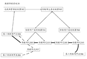
- FIG. 5 is a schematic diagram of determining a data transmission path by a transmission side upper layer controller and a transmission side lower layer controller according to an embodiment of the present disclosure
- FIG. 6 is a structural diagram of a data transmission apparatus according to an embodiment of the present application.
- FIG. 7 is a structural diagram of still another data transmission apparatus according to an embodiment of the present application.
- FIG. 8 is a structural diagram of still another data transmission apparatus according to an embodiment of the present application.
- FIG. 9 is a structural diagram of still another data transmission apparatus according to an embodiment of the present application.
- SDN Software Defined Network
- OpenFlow OpenFlow
- SPTN Software Defined Transport Network
- the SPTN is an evolution and upgrade of the PTN, which can be further extended by open applications and services. This application is based on the idea of enhancing the intelligent scheduling capability of network resources and flattening the relationship between customers and network resources to improve operation and maintenance management and business operation efficiency.
- the application improves the network architecture of the related art, and adds a wireless side management controller, a transmission side upper layer controller, and a plurality of transmission side lower layer controllers.
- the wireless side management controller can monitor communication requirements of multiple base stations, and can analyze communication requirements of multiple base stations to determine an optimal interconnection scheme between the base station and the base station, or between the base station and the EPC entity.
- Sending the determined optimal interconnection scheme information to the upper layer controller of the transmission side, and the upper layer controller of the transmission side may be based on the received interconnection scheme information, and the network of the transmission network element within the scope of its own jurisdiction reported by the plurality of transmission side lower layer controllers Topology, together with the lower-layer controller on the transmission side
- the first interconnect signaling may be sent to the wireless side management controller, and the wireless side management controller may be based on the received first
- the first signaling indicator is sent to the upper layer controller of the transmission side, and the upper layer controller of the transmission side may determine the first network side node and the second network side node after receiving the first interconnection indication information.
- the transmission side upper layer controller of the transmission side can also consider the utilization of the bandwidth resource by the existing data transmission path, and thus can improve Utilization of bandwidth resources.
- FIG. 3 it is a schematic diagram of a data transmission system 30 provided by an embodiment of the present application.
- the first network side node 301 is configured to send the first interconnect signaling to the wireless side management controller, where the first interconnect signaling is used to indicate that the first network side node needs to establish a communication connection with the second network side node.
- the first network side node 301 may be a base station.
- the base station may integrate and analyze the interconnection information between itself and other base station/EPC entities according to the received related information sent by the terminal device, and may The interconnection information generates the first interconnection signaling, and reports the first interconnection signaling to the wireless side management controller.
- the base station can periodically transmit the first interconnection signaling to the radio side management controller.
- the wireless side management controller 302 is configured to send the first interconnection indication information to the upper layer controller of the transmission side based on the received first interconnection signaling, where the first interconnection indication information is used to indicate that the first network side node 301 is established. A data transmission path between the second network side nodes.
- the wireless side management controller 302 may send the first interconnection indication information to the upper controller of the transmission side in response to the communication requirement of the first network side node 301, so as to indicate The transmission side upper layer controller establishes a data transmission path for communication between the first network side node 301 and the second network side node.
- the wireless side management controller 302 may further predict the communication requirement of the first network side node based on the first interconnect signaling sent by the first network side node 301 for a period of time, and based on the predicted first network side.
- the communication requirement between the node 301 and the second network side node establishes a data transmission path for it.
- the transmission side upper layer controller 303 is configured to determine a data transmission path between the first network side node 301 and the second network side node based on the received first interconnection indication information.
- the transmission side upper layer controller 303 determines the first part based on the first interconnection indication information sent by the wireless side management controller 302.
- the data transmission path between the network side node 301 and the second network side node may be composed only of the access layer transmission network element.
- the data transmission between the first network side node 301 and the second network side node may be detoured at the access layer (the path indicated by the dotted line in FIG. 3) without passing through the transmission layer of the aggregation layer and the core layer. In this way, the delay between the first network side node and the second network side node can be effectively alleviated, and the bandwidth resources of the aggregation layer and the core layer can be saved.
- the transmission side lower layer controller 304 is configured to collect the network topology of the plurality of transmission network elements in the jurisdiction of the lower layer controller of the transmission side, and report the network topology to the transmission side upper layer controller 303.
- the transport-side lower-layer controller 304 may also use the topology discovery protocol to determine whether the network topology of the transport network element in its own jurisdiction changes, and determine the network topology of the transport network element in its own jurisdiction.
- the updated network topology within the jurisdiction of the lower layer controller of the transmission side can be re-collected, and the updated network topology can be summarized.
- the report is reported to the transmission side upper layer controller 303.
- the transmission-side lower-layer controller 304 is further configured to receive the boundary path information sent by the transmission-side upper-layer controller 303, where the boundary path information includes multiple boundary transmission network element information, and the boundary transmission network element
- the transmission side lower layer controller 304 determines the internal path information of the lower layer controller of the transmission side based on the boundary path information, and sends the internal path information to the upper layer controller of the transmission side.
- the internal path information includes internal transmission network element information of a boundary transmission network element that is connected to the lower layer controller of the transmission side.
- the transmission side upper layer controller 303 is configured to determine the first network side node 301 and the second according to the internal path information reported by each of the transmission side lower layer controllers and the boundary path information sent by the transmission side upper layer controller 303.
- the data transmission path between the network side nodes (the path shown by the thick lines in Figure 3).
- the transmission network element 305 is configured to transmit data between the first network side node 303 and the second network side node based on the received data transmission path.
- the second network side node 306 is configured to receive data sent by the first network side node based on the foregoing transport network element.
- the wireless side management controller when receiving the interconnection signaling sent by the third network side node, may further combine the determined interconnection indication information of the first network side node and the second network side node. The most reasonable interconnection indication information is generated for the communication requirements of the third network side node.
- the second interconnection signaling may be sent to the wireless side management controller.
- the wireless side management controller may be based on the second interconnection signaling, and information that the communication connection has been established between the second network side node and the first network side node, to the transmission side.
- the upper layer controller sends the second interconnection indication information, where the second interconnection indication information is used to indicate that the third network side node is established and the first a data transmission path between the network side nodes; further, the transmission side upper layer controller may determine a data transmission path between the third network side node and the first network side node based on the received second interconnection indication information.
- the third network side node can multiplex the already established data transmission between the second network side node and the first network side node.
- the path can not only make full use of the bandwidth resources of the transmission side network, but also reduce the operation of repeatedly determining the transmission path by the upper controller on the transmission side.
- the wireless side management controller when the wireless side management controller receives the multiple interconnection signalings sent by the network side nodes, the wireless side management controller may also perform statistics and analysis on the interconnection needs of the network side nodes, and then comb the network side nodes. Better connectivity requires information.
- the wireless side management controller may also be based on the received interconnection signaling, a preset interconnection request response rule, and the plurality of The connection information that has been established by the network side node, and the connection information that has been established by the target network side node that the plurality of network side nodes respectively request to connect, determine the interconnection information of the plurality of network side nodes.
- the interconnection information of each network side node includes other network side node information connected to the network side node.
- preset interconnection request response rules such as the maximum number of connections that the base station can establish at the same time, or the data transmission amount of the base station, etc., which are not enumerated here.
- the preset interconnection request response rule may also be adjusted according to the actual interconnection condition of the plurality of network side nodes; the connection information that has been established by the plurality of network side nodes, and the target that is requested to be connected with the plurality of network side nodes respectively
- the connection information that has been established by the network side node refers to the currently valid connection information of the plurality of network side nodes, and does not include the connection information of the network side node that the wireless side management controller has instructed to remove.
- the wireless side management controller sends the interconnection indication information to the transmission side upper layer controller based on the determined interconnection information, so that the transmission side upper layer controller determines the data transmission path for the plurality of network side nodes.
- the radio side management controller receives the interconnection signaling sent by the base station 3, the base station 4, and the base station 5, and determines that both the base station 3 and the base station 5 need to establish a connection with the base station 1, and the base station 4 needs to establish a connection with the base station 1 and the base station 2, respectively. And, the base station 1 has established an effective connection with the base station 2. Then, the wireless side management controller can analyze these connection requirements. For example, the base station 4 needs to establish a connection with the base station 1 and the base station 2, respectively, and the base station 1 has established an effective connection with the base station 2, then the base station 4 can be directly connected to the base station.
- the base station 1 Establish a connection such that the base station 1 needs to establish a connection with the base station 4 and the base station 2 at the same time. Assuming that the maximum number of connections that the base station 1 can establish at the same time is three, the connection requirement of the base station 1 for the base station 3 and the base station 5 can only satisfy one of them. At this time, the data transmission amount of the base station 3 and the base station 5 can be analyzed. If it is determined that the data transmission amount of the base station 3 is large, the base station 3 establishes a connection with the base station 1 to reject or delay the connection requirement of the base station 5; if it is determined that the data transmission amount of the base station 5 is large, the base station 5 and the base station 1 are established. The connection, rejection or delay response to the connection requirements of the base station 3.
- the wireless side management controller may further send a removal instruction indicating that the data transmission path is removed to the transmission side upper layer controller; correspondingly, the transmission side upper layer control
- the device may remove the data transmission path between the first network side node and the second network side node based on the received teardown instruction, so that the data transmission path between the first network side node and the second network side node is established and removed. It is more flexible and faster, and can increase the data transmission amount of the transmission side network without increasing the transmission network element.
- the first interconnect signaling may be sent to the wireless side management controller, and the wireless side management controller may be based on the received first And the first signaling indication is sent to the upper layer controller of the transmission side, and after receiving the first interconnection indication information, the upper layer controller of the transmission side may determine the relationship between the first network side node and the second network side node.
- Data transmission path such that the first network side node
- the data transmission path with the second network side node may be determined by the transmission side upper layer controller based on the first interconnection indication information sent by the wireless side management controller, and the establishment of the data transmission path does not require manual intervention, and is more flexible.
- the upper-layer controller of the transmission side may also consider the utilization of the bandwidth resource by the existing data transmission path, and thus, the utilization of the bandwidth resource may be improved.
- FIG. 4 a schematic diagram of a connection relationship between a first network side node, a second network side node, a transmission side upper layer controller, a transmission side lower layer controller, and a transmission network element in an application embodiment of the present application,
- the base station 1 It can represent the first network side node;
- the base station 2 the temporary EPC, and the EPC can both represent the second network side node (the temporary EPC is located at the access layer, and the EPC is located at the core layer);
- the PTN device can represent the transport network element.
- the transmission side network mainly includes an access layer, an aggregation layer, and a core layer. Therefore, at least one transmission side lower layer controller may be respectively disposed at the access layer, the aggregation layer, and the core layer, so that each transmission side lower layer control
- the transport network elements in their own jurisdiction are managed separately, and all the lower-layer controllers on the transport side are managed by a transport-side upper-layer controller.
- the network topology of each transport network element in the transmission side network may be established in advance.
- each of the transmission-side lower-layer controllers first collects the network topology of the plurality of transmission network elements in its own jurisdiction, and then reports the collected network topology to the upper-layer controller of the transmission side.
- the lower layer controller on the transmission side can also use the topology discovery protocol to determine whether the network topology of the transmission network element in its own jurisdiction changes, and determine the transmission within its jurisdiction.
- the updated network topology in the jurisdiction of the lower layer controller of the transmission side may be re-collected, and the updated network topology is reported to the upper controller of the transmission side.
- the upper-layer controller on the transmission side forms a network topology structure on the transmission side network according to the network topology structure in its own jurisdiction reported by each lower-layer controller of the transmission side, so as to be a base station and a base station.
- the interconnection between the station/EPC entities determines the data transmission path.
- the base station is interconnected with the base station.
- the base station 1 when the communication connection between the terminal device and the base station 1 needs to be handed over to the base station 2, the base station 1 can analyze that it needs to interconnect with the base station 2 according to the communication switching request of the terminal device; The first interconnect signaling is generated, and the first interconnect signaling is reported to the wireless control management unit.
- the radio side management controller may send the first interconnection indication information to the upper controller of the transmission side, so as to instruct the upper controller of the transmission side to establish data transmission for the communication between the base station 1 and the base station 2. path.
- the transmission side upper layer controller may determine a data transmission path formed by the access layer transmission network element between the base station 1 and the base station 2. In this way, the data transmission between the base station 1 and the base station 2 can be detoured at the access layer (the path indicated by the circular line of the access layer in FIG. 4) without passing through the convergence layer and the core layer, so that not only can the mitigation can be effectively alleviated.
- the delay between the base station 1 and the base station 2 is interconnected, and the bandwidth resources of the aggregation layer and the core layer can be saved.
- the wireless side management controller may The interconnection indication information is generated for the base station 3 by considering the interconnection indication information of the base station 1 and the base station 2 that have been determined, and considering the interface utilization of each transmission network element in the access layer.
- the second interconnection signaling may be sent to the radio side management controller.
- the wireless side management controller may send the second to the upper layer controller of the transmission side based on the second interconnection signaling and the information that the communication connection between the base station 1 and the base station 2 is established.
- Interconnection indication information the second interconnection indication information
- the data transmission path between the base station 3 and the base station 1 is instructed to be established.
- the transmission side upper layer controller may determine a data transmission path between the base station 3 and the base station 1 based on the received second interconnection indication information. In this way, only the data transmission path between the base station 3 and the base station 1 needs to be established, and the base station 3 can multiplex the data transmission path established between the base station 2 and the base station 1, thereby fully utilizing the bandwidth resources of the transmission side network.
- the base station is interconnected with the EPC.
- the process of establishing a data transmission path between the base station and the temporary EPC entity when the temporary EPC entity is located in the access layer (shown in FIG. 4), the process of establishing a data transmission path between the base station and the temporary EPC entity, and the process of establishing a data transmission path between the base station and the base station The same, no longer repeat here.
- the temporary EPC entity in the embodiment of the present application may also be located at the convergence layer or the core layer.
- the path determination between the plurality of transmission side lower layer controllers is involved, and thus the base station and the base station establish a data transmission path in the lower layer controller of the access layer.
- the process is different. The following describes the process of establishing a data transmission path between the base station and the EPC entity.
- each lower layer controller of the transmission side For the transmission network element diagram included in each lower layer controller of the transmission side, it is assumed that the base station is connected to the transmission network element labeled 1, and the EPC entity is connected to the transmission network element labeled 14.
- the upper layer controller of the transmission side first determines the information of the plurality of sets of boundary transmission network elements.
- the determined boundary transmission network element information includes two sets of boundary network element information: 5, 7, 10, 12, 14 and 1, 3, 4, 9, 10, 12, 14, and send the information of these boundary transmission network elements to each of the lower-layer controllers of the transmission side; After receiving the boundary transmission network element information, the lower-layer controller of the transmission side can determine the internal transmission path by combining the usage of each transmission network element within the scope of its own jurisdiction.
- the transmission path determined by the lower layer controller of the access layer is 1 ⁇ 2; the transmission path determined by the lower layer controller of the convergence layer is 5 ⁇ 8 ⁇ 6 ⁇ 7 ⁇ 10, or, 5 ⁇ 6 ⁇ 7 ⁇ 10; the transmission path determined by the lower layer controller of the core layer is 12 ⁇ 14; and for the boundary network element: 1, 3, 4, 9, 10, 12 14, the transmission path determined by the lower layer controller of the access layer is 1 ⁇ 3 ⁇ 4; the transmission path determined by the lower layer controller of the convergence layer is 9 ⁇ 10; the transmission path determined by the lower layer controller of the core layer is 12 ⁇ 14 .
- each of the lower-layer controllers of the transmission side After determining the internal path, each of the lower-layer controllers of the transmission side sends the internal path information to the upper-layer controller of the transmission side. Then, the upper-layer controller of the transmission side can obtain three path information: 1 ⁇ 2 ⁇ 5 ⁇ 8 ⁇ 6 ⁇ 7 ⁇ 10 ⁇ 12 ⁇ 14,1 ⁇ 2 ⁇ 5 ⁇ 6 ⁇ 7 ⁇ 10 ⁇ 12 ⁇ 14, and 1 ⁇ 3 ⁇ 4 ⁇ 9 ⁇ 10 ⁇ 12 ⁇ 14; the upper controller on the transmission side is based on certain selection criteria An optimal data transmission path between the base station and the EPC entity is selected from the three paths.
- the selection criterion may be the shortest data transmission path or the maximum utilization of the transmission network element.
- the process of establishing a data transmission path between the base station and the temporary EPC (not located in the access layer) is similar to the process of establishing a data transmission path between the base station and the EPC entity, and details are not described herein again.
- the base station when the base station establishes a communication connection with the base station or the temporary EPC entity located at the access layer, the data transmitted between the base station and the base station/temporary EPC entity is only detoured at the access layer.
- the virtual local area network Virtual
- the local area network (VLAN) performs data transmission; when the base station establishes a communication connection with the temporary EPC/EPC entity located at the access layer or the core layer, multiple lower layer controllers of the transmission side are involved, and at this time, at the access layer Data can still be transmitted using VLANs, and routing tables can be used for data transmission at the aggregation layer and core layer.
- Wireless side management controller can be weekly
- the interconnection signaling sent by each base station is received periodically, and if the interconnection signaling transmitted by the base station 1 and the base station 2 is not received within a preset time period, for example, 10 minutes, the communication between the base station 1 and the base station 2 can be considered.
- the demand ends.
- the wireless side management controller may send a teardown command to the upper controller of the transmission side, where the teardown command is used to instruct the upper controller of the transmission side to remove the data transmission path between the base station 1 and the base station 2.
- the first interconnect signaling may be sent to the wireless side management controller, and the wireless side management controller may be based on the received first And the first signaling indication is sent to the upper layer controller of the transmission side, and after receiving the first interconnection indication information, the upper layer controller of the transmission side may determine the relationship between the first network side node and the second network side node.
- a data transmission path such that the data transmission path between the first network side node and the second network side node may be determined by the transmission side upper layer controller based on the first interconnection indication information sent by the wireless side management controller, and the data
- the establishment of the transmission path does not require manual intervention and is more flexible.
- the upper layer controller of the transmission side can also consider the utilization of the bandwidth resource by the existing data transmission path, thereby improving the bandwidth resource. Utilization rate.
- the data transmission device corresponding to the data transmission method is also provided in the embodiment of the present application. Since the principle of solving the problem is similar to the data transmission method in the embodiment of the present application, the implementation of the device may refer to the method. Implementation, repetition will not be repeated.
- a structure diagram of a data transmission apparatus 60 provided in an embodiment of the present application, where the apparatus is located in a wireless side management controller, includes:
- the interconnection signaling receiving module 601 is configured to receive the first interconnection signaling sent by the first network side node, where the first interconnection signaling is used to indicate that the first network side node needs to establish a communication connection with the second network side node. ;
- the interconnection indication sending module 602 is configured to send the first interconnection indication information to the upper layer controller of the transmission side, according to the received first interconnection signaling, to indicate that the first network side node and the second network are established.
- the apparatus further includes:
- the teardown instruction sending module 603 is configured to: when it is determined that the communication between the first network side node and the second network side node ends, send an indication to the transmission side upper layer controller to remove the first network side node and the second network side node The removal command of the data transmission path.
- the interconnect signaling receiving module 601 is further configured to:
- the interconnection indication sending module 602 is further configured to:
- the interconnection signaling receiving module 601, the interconnection indication sending module 602, and the tearing instruction sending module 603 can be implemented by a communication interface in the data transmission device 60 in combination with a processor.
- FIG. 7 is a structural diagram of another data transmission apparatus 70 provided by an embodiment of the present application.
- the apparatus is located in an upper layer controller of the transmission side, and includes:
- the interconnection indication receiving module 701 is configured to receive the first interconnection indication information sent by the wireless side management controller;
- the transmission path determining module 702 is configured to determine a data transmission path between the first network side node and the second network side node based on the received first interconnection indication information.
- the transmission path determining module 702 is specifically configured to:
- the boundary path information is sent to the lower layer controller of the transmission side, where the boundary path information includes a plurality of boundary transmission network element information, where the boundary transmission network element is a transmission network element located at a boundary of the lower layer controller of the transmission side;
- the internal path information includes internal transmission network element information of the boundary transmission network element that is connected to the lower layer controller of the transmission side;
- the above data transmission path is determined based on the internal path information and the boundary path information.
- the apparatus further includes:
- the removal command receiving module 703 is configured to receive a removal command sent by the wireless side management controller to indicate the removal of the data transmission path, and remove the data transmission path between the first network side node and the second network side node based on the received removal command.
- the transmission path determining module 702 is specifically configured to:
- the interconnect indication receiving module 701 is further configured to:
- the interconnection indication information is used to instruct the transmission side upper layer controller to determine a data transmission path for the multiple network side nodes; wherein the interconnection indication information is based on the received location Interconnection signaling respectively sent by the plurality of network side nodes, a preset interconnection request response rule, connection information that the plurality of network side nodes have established, and a target that the plurality of network side nodes respectively request to connect The connection information that the network side node has established is determined.
- the transmission path determination module 702 is further configured to:
- a data transmission path is determined for the plurality of network side nodes based on the received interconnection indication information.
- the interconnection indication receiving module 701 can be implemented by a communication interface in the data transmission device 70; the transmission path determination module 702 can be implemented by a processor in the data transmission device 70; the teardown instruction receiving module 703 can be implemented by a data transmission device.
- the processor in 70 is implemented in conjunction with a communication interface.
- a structure diagram of a data transmission device 80 is provided in the embodiment of the present application.
- the device is located in the lower layer controller of the transmission side, and includes:
- the topology collection module 801 is configured to collect network topology structures of multiple transmission network elements within the jurisdiction of the lower layer controller of the transmission side;
- the topology reporting module 802 is configured to report the network topology to the upper controller of the transmission side.
- the apparatus further includes:
- the transmission path determining module 803 is configured to receive the boundary path information sent by the upper layer controller of the transmission side, where the boundary path information includes multiple boundary transmission network element information, where the boundary transmission network element is located at the lower layer controller boundary of the transmission side Transmission network element;
- the internal path information includes a boundary transmission network element connected to the lower layer controller of the transmission side Internal transmission network element information.
- the topology collecting module 801 and the transmission path determining module 803 can be implemented by a processor in the data transmission device 80 in combination with a communication interface; the topology reporting module 802 can be implemented by a communication interface in the data transmission device 80.
- FIG. 9 is a structural diagram of another data transmission apparatus 90 provided by the embodiment of the present application.
- the apparatus is located in the wireless side management controller, and includes:
- the receiving module 901 is configured to receive interconnection signaling sent by multiple network side nodes respectively.
- the interconnection information determining module 902 is configured to: based on the received interconnection signaling, a preset interconnection request response rule, connection information that multiple network side nodes have established, and a plurality of network side nodes respectively request a connection target
- the connection information that has been established by the network side node determines the interconnection information of the multiple network side nodes, where the interconnection information of each network side node includes other network side node information connected to the network side node;
- the sending module 903 is configured to send the upper layer controller to the transmission side based on the determined interconnection information.
- the interconnection indication information is sent, and the sent interconnection indication information is used to instruct the transmission side upper layer controller to determine a data transmission path for the plurality of network side nodes.
- the receiving module 901 can be implemented by a communication interface in the data transmission device 90; the interconnection information determining module 902 and the transmitting module 903 can be implemented by a processor in the data transmission device 90 in conjunction with a communication interface.
- embodiments of the present application can be provided as a method, system, or computer program product.
- the present application can take the form of an entirely hardware embodiment, an entirely software embodiment, or an embodiment in combination of software and hardware.
- the application can take the form of a computer program product embodied on one or more computer-usable storage media (including but not limited to disk storage, CD-ROM, optical storage, etc.) including computer usable program code.
- the computer program instructions can also be stored in a computer readable memory that can direct a computer or other programmable data processing device to operate in a particular manner, such that the instructions stored in the computer readable memory produce an article of manufacture comprising the instruction device.
- the apparatus implements the functions specified in one or more blocks of a flow or a flow and/or block diagram of the flowchart.
- the embodiment of the present application further provides a computer readable storage medium, where the computer program is stored, and when the computer program is executed by the processor, the method of the wireless side management controller side is implemented, or the above-mentioned transmission side upper layer control is implemented.
- the first interconnect signaling may be sent to the wireless side management controller, and the wireless side management controller may be based on the received Transmitting, by the first interconnect signaling, the first interconnect indication information to the upper controller of the transmission side; after receiving the first interconnection indication information, the upper controller of the transmission side may determine the first network side node and the second network side node a data transmission path, such that the data transmission path between the first network side node and the second network side node can be determined by the transmission side upper layer controller based on the first interconnection indication information sent by the wireless side management controller, and The establishment of the data transmission path does not require manual intervention and is more flexible.
- the upper layer controller of the transmission side can also consider the utilization of the bandwidth resource by the existing data transmission path. Therefore, the utilization of bandwidth resources can be improved.
Landscapes
- Engineering & Computer Science (AREA)
- Computer Security & Cryptography (AREA)
- Computer Networks & Wireless Communication (AREA)
- Signal Processing (AREA)
- Mobile Radio Communication Systems (AREA)
Abstract
本申请涉及一种数据传输系统、方法、装置及计算机可读存储介质;本申请实施例提供的数据传输系统包括:第一网络侧节点,配置为向无线侧管理控制器发送第一互联信令;其中,所述第一互联信令用于指示所述第一网络侧节点需要与第二网络侧节点建立通信连接;无线侧管理控制器,配置为基于接收的所述第一互联信令,向传输侧上层控制器发送第一互连指示信息,配置为指示建立所述第一网络侧节点与第二网络侧节点之间的数据传输路径;传输侧上层控制器,配置为基于接收的所述第一互连指示信息,确定所述第一网络侧节点与第二网络侧节点之间的数据传输路径。
Description
相关申请的交叉引用
本申请基于申请号为201611010022.1、申请日为2016年11月16日的中国专利申请提出,并要求该中国专利申请的优先权,该中国专利申请的全部内容在此引入本申请作为参考。
本申请涉及通信技术领域,尤其涉及一种数据传输系统、方法、装置及计算机可读存储介质。
随着无线通信设备种类和数量的快速增长,日益丰富的无线应用业务对无线网络的吞吐量、数据传输速率及时延提出了更高的要求,正是在这种背景下,长期演进第5代(Long Time Evolution 5Generation,LTE 5G)移动通信标准应运而生。
如图1所示,相关技术的LTE架构由核心网(Evolved Packet Core,EPC)和接入网(Evolved UMTS Terrestrial Radio Access Network,E-UTRAN)组成。其中,EPC包括多个逻辑节点,如服务网关(Serving GateWay,SGW)等,而E-UTRAN由多个基站(Evolved Node B,eNB)支撑。eNB与EPC之间通过S1接口进行通信,传递用户数据与信令,eNB之间通过X2接口进行通信,交互信息。如图2所示,eNB的无线侧数据主要通过无线网络层和传输网络层进行传递,eNB与eNB/EPC之间的数据传递需要预先手动建立数据传输通道,并预留带宽,如果建立的数据通道中没有数据传递,则会造成带宽资源浪费,而这些数据传输通道一旦建立就不易拆除,灵活
性比较差。此外,在TD-LTE传输网络层网中,eNB之间传送的数据全部通过L3分组传输网(Packet Transport Network,PTN)设备在本地网内疏通,具体地,对eNB之间传送的数据按照接入层→汇聚层→核心层→汇聚层→接入层的方式进行传递,这种方式不但会导致eNB之间的互联时延比较大,而且会占用汇聚层和接入层较多带宽资源。
目前,针对4G+以及以后的5G、6G时代,一些如LTE跨基站载波聚合、移动边缘计算(Mobile Edge Computing,MEC)等新兴业务对无线网络的灵活性、以及带宽都提出了更高、更苛刻的要求,而现有传输网络层的连接方式远远不能满足这些业务需求。可见,现有的无线网络数据传输方式存在着灵活性差、对带宽资源利用率低的问题。
发明内容
为解决相关技术问题,本申请实施例提供一种数据传输系统、方法及装置及计算机可读存储介质。
本申请实施例提供的一种数据传输系统,包括:
第一网络侧节点,配置为向无线侧管理控制器发送第一互联信令;其中,所述第一互联信令用于指示所述第一网络侧节点需要与第二网络侧节点建立通信连接;
无线侧管理控制器,配置为基于接收的所述第一互联信令,向传输侧上层控制器发送第一互连指示信息,所述第一互联指示信息用于指示建立所述第一网络侧节点与第二网络侧节点之间的数据传输路径;
传输侧上层控制器,配置为基于接收的所述第一互连指示信息,确定所述第一网络侧节点与第二网络侧节点之间的数据传输路径。
上述方案中,所述无线侧管理控制器,还配置为:
当确定所述第一网络侧节点与所述第二网络侧节点之间的通信结束时,向所述传输侧上层控制器发送指示拆除所述数据传输路径的拆除指令;
所述传输侧上层控制器还配置为,基于接收的所述拆除指令,拆除所述第一网络侧节点与第二网络侧节点之间的数据传输路径。
上述方案中,所述系统还包括:
传输侧下层控制器,配置为搜集所述传输侧下层控制器管辖范围内的多个传输网元的网络拓扑结构,并将所述网络拓扑结构上报给所述传输侧上层控制器;还配置为接收所述传输侧上层控制器下发的数据传输路径,并将该数据传输路径发送给该数据传输路径中的各个传输网元;
所述传输侧上层控制器配置为:
基于所述传输侧下层控制器上报的传输网元的网络拓扑结构、以及接收的所述第一互连指示信息,确定所述第一网络侧节点与第二网络侧节点之间的数据传输路径;
所述传输网元,配置为基于接收的所述数据传输路径,对所述第一网络侧节点与第二网络侧节点之间的数据进行传输。
上述方案中,所述传输侧下层控制器还配置为:
接收所述传输侧上层控制器下发的边界路径信息;所述边界路径信息中包含多个边界传输网元信息,所述边界传输网元为位于传输侧下层控制器边界的传输网元;基于所述边界路径信息,确定所述传输侧下层控制器的内部路径信息,并将该内部路径信息发送给所述传输侧上层控制器;所述内部路径信息中包含连接该传输侧下层控制器的边界传输网元的内部传输网元信息;
所述传输侧上层控制器配置为:
根据所述传输侧下层控制器上报的内部路径信息,以及所述边界路径信息,确定所述数据传输路径。
上述方案中,所述传输侧下层控制器还配置为:
当所述传输侧下层控制器管辖范围内传输网元的网络拓扑结构发生变
化时,重新搜集该传输侧下层控制器管辖范围内更新后的网络拓扑结构,并将所述更新后的网络拓扑结构上报给所述传输侧上层控制器。
上述方案中,所述第二网络侧节点为基站,或位于接入层的临时核心网实体;
所述传输侧上层控制器,配置为:
基于所述无线侧管理控制器发送的所述第一互连指示信息,确定所述第一网络侧节点与第二网络侧节点之间、由接入层传输网元组成的数据传输路径。
上述方案中,所述无线侧管理控制器还配置为:
接收多个网络侧节点分别发送的互连信令;
基于接收的所述互连信令、预先设定的互连请求响应规则、多个网络侧节点已经建立的连接信息,以及多个网络侧节点分别请求连接的目标网络侧节点已经建立的连接信息,确定多个网络侧节点的互联信息,其中,每个网络侧节点的互连信息中包含与该网络侧节点连接的其它网络侧节点信息;
基于确定的所述互连信息,向传输侧上层控制器发送互连指示信息,发送的互连指示信息用于指示传输侧上层控制器为多个网络侧节点确定数据传输路径。
所述传输侧上层控制器,还配置为:
基于接收的所述第二互连指示信息,确定所述第三网络侧节点与第一网络侧节点之间的数据传输路径。
本申请实施例提供的一种数据传输方法,包括:
第一网络侧节点向无线侧管理控制器发送第一互联信令;其中,所述第一互联信令用于指示所述第一网络侧节点需要与第二网络侧节点建立通信连接;
无线侧管理控制器基于接收的所述第一互联信令,向传输侧上层控制器发送第一互连指示信息,所述第一互连指示信息用于指示建立所述第一网络侧节点与第二网络侧节点之间的数据传输路径;
传输侧上层控制器基于接收的所述第一互连指示信息,确定所述第一网络侧节点与第二网络侧节点之间的数据传输路径。
上述方案中,所述方法还包括:
当所述无线侧管理控制器确定所述第一网络侧节点与所述第二网络侧节点之间的通信结束时,向所述传输侧上层控制器发送指示拆除所述数据传输路径的拆除指令;
所述传输侧上层控制器基于接收的所述拆除指令,拆除所述第一网络侧节点与第二网络侧节点之间的数据传输路径。
上述方案中,传输侧上层控制器确定所述第一网络侧节点与第二网络侧节点之间的数据传输路径之前,所述方法还包括:
传输侧下层控制器搜集所述传输侧下层控制器管辖范围内的多个传输网元的网络拓扑结构,并将所述网络拓扑结构上报给所述传输侧上层控制器;
所述传输侧上层控制器基于接收的所述第一互连指示信息,确定所述第一网络侧节点与第二网络侧节点之间的数据传输路径,包括:
所述传输侧上层控制器基于所述传输侧下层控制器上报的传输网元的网络拓扑结构、以及接收的所述第一互连指示信息,确定所述第一网络侧节点与第二网络侧节点之间的数据传输路径。
上述方案中,所述方法还包括:
所述传输侧下层控制器接收所述传输侧上层控制器下发的数据传输路径,并将该数据传输路径发送给该数据传输路径中的各个传输网元;
所述传输网元基于接收的所述数据传输路径,对所述第一网络侧节点
与第二网络侧节点之间的数据进行传输。
上述方案中,所述传输侧上层控制器确定所述第一网络侧节点与第二网络侧节点之间的数据传输路径,包括:
所述传输侧下层控制器管接收所述传输侧上层控制器下发的边界路径信息;所述边界路径信息中包含多个边界传输网元信息,所述边界传输网元为位于传输侧下层控制器边界的传输网元;
基于所述边界路径信息,确定所述传输侧下层控制器的内部路径信息,并将该内部路径信息发送给所述传输侧上层控制器;所述内部路径信息中包含连接该传输侧下层控制器的边界传输网元的内部传输网元信息;
所述传输侧上层控制器根据所述传输侧下层控制器上报的内部路径信息,以及所述边界路径信息,确定所述数据传输路径。
上述方案中,所述第二网络侧节点为基站,或位于接入层的临时核心网实体;所述传输侧上层控制器基于接收的所述第一互连指示信息,确定所述第一网络侧节点与第二网络侧节点之间的数据传输路径,包括:
所述传输侧上层控制器基于接收的所述第一互连指示信息,确定所述第一网络侧节点与第二网络侧节点之间、由接入层传输网元组成的数据传输路径。
上述方案中,所述方法还包括:
无线侧管理控制器接收多个网络侧节点分别发送的互连信令;
基于接收的互连信令、预先设定的互连请求响应规则、所述多个网络侧节点已经建立的连接信息,以及所述多个网络侧节点分别请求连接的目标网络侧节点已经建立的连接信息,确定所述多个网络侧节点的互联信息,其中,每个网络侧节点的互连信息中包含与该网络侧节点连接的其它网络侧节点信息;
基于确定的所述互连信息,向传输侧上层控制器发送互连指示信息,
发送的互联指示信息用于指示传输侧上层控制器为所述多个网络侧节点确定数据传输路径。
本申请实施例提供的一种数据传输装置,位于无线侧管理控制器中,包括:
互联信令接收模块,配置为接收第一网络侧节点发送的第一互联信令;其中,所述第一互联信令配置为指示所述第一网络侧节点需要与第二网络侧节点建立通信连接;
互连指示发送模块,配置为基于接收的所述第一互联信令,向传输侧上层控制器发送第一互连指示信息,所述第一互连指示信息用于指示建立所述第一网络侧节点与第二网络侧节点之间的数据传输路径。
本申请实施例提供的又一种数据传输装置,位于传输侧上层控制器中,包括:
互连指示接收模块,配置为接收无线侧管理控制器发送的第一互连指示信息;
传输路径确定模块,配置为基于接收的所述第一互连指示信息,确定第一网络侧节点与第二网络侧节点之间的数据传输路径。
本申请实施例提供的再一种数据传输装置,位于传输侧下层控制器中,包括:
搜集模块,配置为搜集所述传输侧下层控制器管辖范围内的多个传输网元的网络拓扑结构;
上报模块,配置为将所述网络拓扑结构上报给传输侧上层控制器。
本申请实施例还提供一种数据传输装置,位于无线侧管理控制器中,包括:
接收模块,配置为接收多个网络侧节点分别发送的互连信令;
互联信息确定模块,配置为基于接收的所述互连信令、预先设定的互
连请求响应规则、多个网络侧节点已经建立的连接信息,以及多个网络侧节点分别请求连接的目标网络侧节点已经建立的连接信息,确定多个网络侧节点的互联信息,其中,每个网络侧节点的互连信息中包含与该网络侧节点连接的其它网络侧节点信息;
发送模块,配置为基于确定的所述互连信息,向传输侧上层控制器发送互连指示信息,发送的互连指示信息用于指示传输侧上层控制器为多个网络侧节点确定数据传输路径。
本申请实施例还提供一种数据传输方法,包括:
无线侧管理控制器接收第一网络侧节点发送的第一互联信令;其中,所述第一互联信令用于指示所述第一网络侧节点需要与第二网络侧节点建立通信连接;
所述无线侧管理控制器基于接收的所述第一互联信令,向传输侧上层控制器发送第一互连指示信息,所述第一互连指示信息用于指示建立所述第一网络侧节点与第二网络侧节点之间的数据传输路径。
本申请实施例又提供了一种数据传输方法,包括:
传输侧上层控制器接收无线侧管理控制器发送的第一互连指示信息;
所述传输侧上层控制器基于接收的所述第一互连指示信息,确定第一网络侧节点与第二网络侧节点之间的数据传输路径。
本申请实施例还提供了一种数据传输方法,包括:
传输侧下层控制器搜集所述传输侧下层控制器管辖范围内的多个传输网元的网络拓扑结构;
所述传输侧下层控制器将所述网络拓扑结构上报给传输侧上层控制器。
本申请实施例又提供了一种数据传输方法,包括:
无线侧管理控制器接收多个网络侧节点分别发送的互连信令;
无线侧管理控制器基于接收的所述互连信令、预先设定的互连请求响应规则、所述多个网络侧节点已经建立的连接信息,以及所述多个网络侧节点分别请求连接的目标网络侧节点已经建立的连接信息,确定所述多个网络侧节点的互联信息,其中,每个网络侧节点的互连信息中包含与该网络侧节点连接的其它网络侧节点信息;
无线侧管理控制器基于确定的所述互连信息,向传输侧上层控制器发送互连指示信息,发送的互连指示信息用于指示传输侧上层控制器为所述多个网络侧节点确定数据传输路径。
本申请实施例还提供了一种计算机可读存储介质,其上存储有计算机程序,所述计算机程序被处理器执行时实现实现上述无线侧管理控制器侧的方法,或者实现上述传输侧上层控制器侧的方法,或者实现上述传输侧下层控制器侧的方法。
本申请实施例中,当第一网络侧节点需要与第二网络侧节点进行数据传输时,可以向无线侧管理控制器发送第一互连信令,无线侧管理控制器可以基于接收的第一互联信令,向传输侧上层控制器发送第一互连指示信息;传输侧上层控制器在接收到第一互连指示信息之后,可以确定第一网络侧节点与第二网络侧节点之间的数据传输路径,这样,第一网络侧节点与第二网络侧节点之间的数据传输路径可以由传输侧上层控制器基于无线侧管理控制器发送的第一互连指示信息来确定,并且该数据传输路径的建立不需要人工干预,更加灵活,此外,传输侧上层控制器在确定该数据传输路径时,还可以考虑已有的数据传输路径对带宽资源的利用情况,因此,可以提高带宽资源的利用率。
图1为相关技术中LTE的架构示意图;
图2为相关技术中基站之间进行互联的示意图;
图3为本申请实施例提供的数据传输系统示意图;
图4为本申请实施例提供的又一数据传输系统示意图;
图5为本申请实施例提供的传输侧上层控制器和传输侧下层控制器确定数据传输路径的示意图;
图6为本申请实施例提供的数据传输装置结构图;
图7为本申请实施例提供的又一数据传输装置结构图;
图8为本申请实施例提供的再一数据传输装置结构图;
图9为本申请实施例提供的再一数据传输装置结构图。
软件定义网络(Software Defined Network,SDN)是由美国斯坦福大学clean slate研究组提出的一种新型网络创新架构,其核心技术OpenFlow通过将网络设备控制面与数据面分离,从而实现了对网络中数据流量的灵活控制,为核心网络的应用创新提供了良好的平台。如果将SDN与相关技术传输网络中的PTN结合起来,就形成了软件定义分组传送网络(Software Packet Transport Network,SPTN),SPTN是PTN的演进和升级,它可以通过开放性的应用和服务,进一步增强网络资源的智能化调度能力、扁平化客户与网络资源之间的关系,从而提升运维管理和业务运营效率,本申请正是基于这一思想提出的。
本申请对相关技术的网络架构进行了改进,增加了无线侧管理控制器、传输侧上层控制器,以及多个传输侧下层控制器。其中,无线侧管理控制器可以监测多个基站的通信需求,并且可以对多个基站的通信需求进行分析,确定出基站与基站,或者基站与EPC实体之间最优的互联方案,进一步地,将确定出的最优的互联方案信息发送给传输侧上层控制器,传输侧上层控制器可以基于接收的互联方案信息,和多个传输侧下层控制器上报的自身管辖范围内传输网元的网络拓扑结构,与传输侧下层控制器一起确
定基站或者基站与EPC实体之间的数据传输路径。
本申请实施例中,当第一网络侧节点需要与第二网络侧节点进行数据传输时,可以向无线侧管理控制器发送第一互连信令,无线侧管理控制器可以基于接收的第一互联信令,向传输侧上层控制器发送第一互连指示信息,进一步地,传输侧上层控制器在接收到第一互连指示信息之后,可以确定第一网络侧节点与第二网络侧节点之间的数据传输路径,这样,第一网络侧节点与第二网络侧节点之间的数据传输路径可以由传输侧上层控制器基于无线侧管理控制器发送的第一互连指示信息来确定,并且该数据传输路径的建立不需要人工干预,更加灵活,此外,传输侧上层控制器在确定该数据传输路径时,还可以考虑已有的数据传输路径对带宽资源的利用情况,因此,可以提高带宽资源的利用率。
下面结合说明书附图对本申请实施例作进一步详细描述。
如图3所示,为本申请实施例提供的数据传输系统30示意图。
第一网络侧节点301,配置为向无线侧管理控制器发送第一互联信令;其中,第一互联信令用于指示第一网络侧节点需要与第二网络侧节点建立通信连接。
在具体实施过程中,第一网络侧节点301可以为基站,此时,基站可以根据收到的终端设备发送的相关信息,整合分析出自身与其它基站/EPC实体的互联信息,并且可以根据这些互联信息生成第一互联信令;并将该第一互联信令上报给无线侧管理控制器。此外,因为基站的互联信息会不断地发生变化,所以,基站可以周期性地向无线侧管理控制器发送第一互联信令。
无线侧管理控制器302,配置为基于接收的第一互联信令,向传输侧上层控制器发送第一互连指示信息,发送的第一互联指示信息用于指示建立第一网络侧节点301与第二网络侧节点之间的数据传输路径。
在具体实施过程中,无线侧管理控制器302可以在接收第一互联信令之后,就响应第一网络侧节点301的通信需求,向传输侧上层控制器发送第一互连指示信息,以便指示传输侧上层控制器为第一网络侧节点301与第二网络侧节点之间的通信建立数据传输路径。
此外,无线侧管理控制器302还可以基于第一网络侧节点301在一段时间内发送的第一互联信令,对该第一网络侧节点的通信需求进行预测,并基于预测的第一网络侧节点301与第二网络侧节点之间的通信需求,为其建立数据传输路径。
传输侧上层控制器303,配置为基于接收的第一互连指示信息,确定第一网络侧节点301与第二网络侧节点之间的数据传输路径。
在具体实施过程中,若第二网络侧节点为基站,或位于接入层的临时EPC实体,传输侧上层控制器303基于无线侧管理控制器302发送的第一互连指示信息,确定的第一网络侧节点301与第二网络侧节点之间的数据传输路径可以仅由接入层传输网元组成。此时,第一网络侧节点301与第二网络侧节点之间的数据传输可以在接入层进行迂回(图3中虚线所示路径),而不用再经过汇聚层和核心层的传输网元,这样,可以有效缓解第一网络侧节点与第二网络侧节点之间进行互联时的延迟,而且可以节省汇聚层和核心层的带宽资源。
传输侧下层控制器304,配置为搜集传输侧下层控制器管辖范围内的多个传输网元的网络拓扑结构,并将该网络拓扑结构上报给传输侧上层控制器303。
在一些实施例中,传输侧下层控制器304还可以利用拓扑发现协议来确定自身管辖范围内传输网元的网络拓扑结构是否发生变化,当确定自身管辖范围内传输网元的网络拓扑结构发生变化时,可以重新搜集该传输侧下层控制器管辖范围内更新后的网络拓扑结构,并将更新后的网络拓扑结
构上报给传输侧上层控制器303。
在具体实施过程中,传输侧下层控制器304还配置为接收传输侧上层控制器303下发的边界路径信息;其中,该边界路径信息中包含多个边界传输网元信息,该边界传输网元为位于传输侧下层控制器边界的传输网元,传输侧下层控制器304基于该边界路径信息,确定该传输侧下层控制器的内部路径信息,并将该内部路径信息发送给传输侧上层控制器303,该内部路径信息中包含连接该传输侧下层控制器的边界传输网元的内部传输网元信息。
相应地,传输侧上层控制器303具体配置为,根据各传输侧下层控制器上报的内部路径信息,以及传输侧上层控制器303下发的边界路径信息,确定第一网络侧节点301与第二网络侧节点之间的数据传输路径(图3中粗线条所示路径)。
传输网元305,配置为基于接收的所述数据传输路径,对第一网络侧节点303与第二网络侧节点之间的数据进行传输。
第二网络侧节点306,配置为基于上述传输网元接收所述第一网络侧节点发送的数据。
此外,在具体实施过程中,无线侧管理控制器在接收第三网络侧节点发送的互连信令时,还可以结合已经确定的第一网络侧节点与第二网络侧节点的互联指示信息,为第三网络侧节点的通信需求生成最合理的互连指示信息。
具体地,当第三网络侧节点需要与第二网络侧节点建立通信连接时,可以向无线侧管理控制器发送第二互连信令。无线侧管理控制器在接收到该第二互连信令后,可以基于该第二互联信令,以及第二网络侧节点与第一网络侧节点之间已建立通信连接的信息,向传输侧上层控制器发送第二互连指示信息,该第二互连指示信息用于指示建立第三网络侧节点与第一
网络侧节点之间的数据传输路径;进一步地,传输侧上层控制器可以基于接收的第二互连指示信息,确定第三网络侧节点与第一网络侧节点之间的数据传输路径。这样,只需要为第三网络侧节点与第一网络侧节点之间建立数据传输路径,第三网络侧节点就可以复用第二网络侧节点与第一网络侧节点之间已经建立的数据传输路径,不但可以充分利用传输侧网络的带宽资源,而且可以减少传输侧上层控制器重复确定传输路径的操作。
在一些实施例中,无线侧管理控制器接收到各网络侧节点发送的多个互连信令时,还可以对各网络侧节点的互联需要进行统计和分析,进而梳理出各网络侧节点之间更优的互联需要信息。
在具体实施过程中,如果无线侧管理控制器接收了多个网络侧节点分别发送的互连信令,还可以基于接收的互连信令、预先设定的互连请求响应规则、这多个网络侧节点已经建立的连接信息,以及与这多个网络侧节点分别请求连接的目标网络侧节点已经建立的连接信息,确定这多个网络侧节点的互联信息。这里,每个网络侧节点的互连信息中包含与该网络侧节点连接的其它网络侧节点信息。其中,预先设定的互连请求响应规则有很多,比如基站同时可以建立的最大连接数、或基站的数据传送量等,在此不再一一列举。此外,预先设定的互连请求响应规则还可以根据多个网络侧节点实际的互联情况进行调整;多个网络侧节点已经建立的连接信息、以及与这多个网络侧节点分别请求连接的目标网络侧节点已经建立的连接信息,均指代这多个网络侧节点当前有效的连接信息,不包括无线侧管理控制器已经指示拆除的网络侧节点的连接信息。
进一步地,无线侧管理控制器再基于确定的上述互连信息,向传输侧上层控制器发送互连指示信息,以便传输侧上层控制器为这多个网络侧节点确定数据传输路径。
下面,以多个网络侧节点都为基站为例,对上述过程进行说明。
假设无线侧管理控制器接收到基站3、基站4、基站5分别发送的互连信令,确定基站3、基站5都需要与基站1建立连接,基站4需要分别与基站1、基站2建立连接,并且,基站1已经与基站2建立有效连接。那么,无线侧管理控制器可以对这些连接需求进行分析,比如,基站4需要分别与基站1、基站2建立连接,而基站1已经与基站2建立有效连接,那么,可以让基站4直接与基站1建立连接,这样,基站1需要同时与基站4和基站2建立连接。假设基站1同时可以建立的最大连接数为3,那么,基站1对于基站3和基站5的连接需求只能满足其中之一,此时,可以对基站3和基站5的数据传送量进行分析,若确定基站3的数据传送量较大,则为基站3与基站1建立连接,拒绝或延迟响应基站5的连接需求;若确定基站5的数据传送量较大,则为基站5与基站1建立连接,拒绝或延迟响应基站3的连接需求。
在具体实施过程中,为了使第一网络侧节点与第二网络侧节点之间的数据传输更加灵活,也为了更好地利用传输侧网络的带宽资源。无线侧管理控制器在确定第一网络侧节点与第二网络侧节点之间的通信结束时,还可以向传输侧上层控制器发送指示拆除数据传输路径的拆除指令;相应地,传输侧上层控制器可以基于接收的拆除指令,拆除第一网络侧节点与第二网络侧节点之间的数据传输路径,这样,第一网络侧节点与第二网络侧节点之间数据传输路径的建立和拆除都更加灵活、快捷,可以在不增加传输网元的前提下,提高传输侧网络的数据传送量。
本申请实施例中,当第一网络侧节点需要与第二网络侧节点进行数据传输时,可以向无线侧管理控制器发送第一互连信令,无线侧管理控制器可以基于接收的第一互联信令,向传输侧上层控制器发送第一互连指示信息,传输侧上层控制器在接收到第一互连指示信息之后,可以确定第一网络侧节点与第二网络侧节点之间的数据传输路径,这样,第一网络侧节点
与第二网络侧节点之间的数据传输路径可以由传输侧上层控制器基于无线侧管理控制器发送的第一互连指示信息来确定,并且该数据传输路径的建立不需要人工干预,更加灵活,此外,传输侧上层控制器在确定该数据传输路径时,还可以考虑已有的数据传输路径对带宽资源的利用情况,因此,可以提高带宽资源的利用率。
下面结合附图对本申请实施例中的数据传输方法做进一步的介绍。
如图4所示,为本申请应用实施例中第一网络侧节点、第二网络侧节点、传输侧上层控制器、传输侧下层控制器,以及传输网元的连接关系示意图,其中,基站1可以代表第一网络侧节点;基站2、临时EPC、EPC均可以代表第二网络侧节点(临时EPC位于接入层,EPC位于核心层);PTN设备可以代表传输网元。
在具体实施过程中,传输侧网络主要包括接入层、汇聚层和核心层,因此,可以在接入层、汇聚层和核心层分别设置至少一个传输侧下层控制器,以便各传输侧下层控制器分别对自身管辖范围内的传输网元进行管理,所有的传输侧下层控制器由一个传输侧上层控制器进行管理。在一些实施例中,可以预先建立传输侧网络中各传输网元的网络拓扑结构。
具体地,各个传输侧下层控制器先搜集自身管辖范围内的多个传输网元的网络拓扑结构,然后,将各自搜集的网络拓扑结构上报给传输侧上层控制器。此外,因为整个传输侧网络的拓扑结构有可能发生变化,传输侧下层控制器还可以利用拓扑发现协议来确定自身管辖范围内传输网元的网络拓扑结构是否发生变化,当确定自身管辖范围内传输网元的网络拓扑结构发生变化时,可以重新搜集该传输侧下层控制器管辖范围内更新后的网络拓扑结构,并将更新后的网络拓扑结构上报给传输侧上层控制器。
传输侧上层控制器根据各个传输侧下层控制器上报的自身管辖范围内的网络拓扑结构,形成关于传输侧网络的网络拓扑结构,以便为基站与基
站/EPC实体之间的互联确定数据传输路径。
下面分别对本申请应用实施例中基站与基站、以及基站与EPC实体之间进行互联的情况分别进行说明。
1)基站与基站进行互联。
在具体实施过程中,当终端设备与基站1之间的通信连接需要切换到基站2时,基站1可以根据该终端设备的通信切换请求,分析出自身需要与基站2进行互联;基于该互联信息生成第一互联信令,并将该第一互联信令上报给无线控制管理单元。
无线侧管理控制器在接收到第一互联信令之后,可以向传输侧上层控制器发送第一互连指示信息,以便指示传输侧上层控制器为基站1与基站2之间的通信建立数据传输路径。
传输侧上层控制器在接收到第一互连指示信息后,可以确定基站1与基站2之间、由接入层传输网元组成的数据传输路径。这样,基站1与基站2之间的数据传输可以在接入层进行迂回(图4中接入层的环形线条所示路径),而不用再经过汇聚层和核心层,这样,不但可以有效缓解基站1与基站2之间进行互联时的延迟,而且可以节省汇聚层和核心层的带宽资源。
在具体实施过程中,当基站1与基站2在接入层传输网元建立数据传输路径之后,如果无线侧管理控制器再接收到基站3发送的互连信令,该无线侧管理控制器可以结合已经确定的基站1与基站2的互联指示信息,再考虑接入层各个传输网元的接口利用情况,为基站3生成互联指示信息。
具体地,当基站3需要与基站2建立通信连接时,可以向无线侧管理控制器发送第二互连信令。无线侧管理控制器在接收到该第二互连信令后,可以基于该第二互联信令,以及基站1与基站2之间已建立通信连接的信息,向传输侧上层控制器发送第二互连指示信息,该第二互连指示信息用
于指示建立基站3与基站1之间的数据传输路径,进一步地,传输侧上层控制器可以基于接收的第二互连指示信息,确定基站3与基站1之间的数据传输路径。这样,只需要为基站3与基站1之间建立数据传输路径,基站3就可以复用基站2与基站1之间已经建立的数据传输路径,进而充分利用传输侧网络的带宽资源。
2)基站与EPC进行互联。
在MEC的业务场景中,某些地区临时有数据传输需求,此时就需要采用分布式SGW来进行数据传输以保证较低的业务时延,这样,如果使用传统的传输侧网络架构来临时建立从基站到某个临时EPC实体的数据传输路径,不但效率极低而且不容易对数据传输路径进行拆除,本申请实施例则可以很好地解决这些问题。
在具体实施过程中,当临时EPC实体位于接入层时(图4所示),基站与该临时EPC实体之间建立数据传输路径的过程,和上述基站与基站之间建立数据传输路径的过程相同,在此不再赘述。
此外,本申请实施例中的临时EPC实体还可以位于汇聚层或核心层。此时,基站与临时EPC/EPC实体建立数据传输路径时,会涉及到多个传输侧下层控制器之间的路径确定,因此和基站与基站在接入层的下层控制器中建立数据传输路径的过程有所不同,下面对基站与EPC实体之间建立数据传输路径的过程进行说明。
具体地,如图5所示,为各个传输侧下层控制器内包含的传输网元示意图,假设基站与标号为1的传输网元相连,EPC实体与标号为14的传输网元相连。当确定基站与EPC实体之间的数据传输路径时,传输侧上层控制器首先确定多组边界传输网元信息,比如确定的边界传输网元信息中包含两组边界网元信息:1、2、5、7、10、12、14和1、3、4、9、10、12、14,并将这些边界传输网元的信息发送给各个传输侧下层控制器;各个传
输侧下层控制器接收到这些边界传输网元信息以后,可以分别在自身管辖的范围内结合各个传输网元的使用情况,确定出内部的传输路径。比如,对于边界网元:1、2、5、7、10、12、14,接入层的下层控制器确定的传输路径为1→2;汇聚层的下层控制器确定的传输路径为5→8→6→7→10,或,5→6→7→10;核心层的下层控制器确定的传输路径为12→14;而对于边界网元:1、3、4、9、10、12、14,接入层的下层控制器确定的传输路径为1→3→4;汇聚层的下层控制器确定的传输路径为9→10;核心层的下层控制器确定的传输路径为12→14。各个传输侧下层控制器在确定内部路径之后,再将这些内部路径信息发送给传输侧上层控制器,那么,传输侧上层控制器可以得到3条路径信息:1→2→5→8→6→7→10→12→14,1→2→5→6→7→10→12→14,以及1→3→4→9→10→12→14;传输侧上层控制器再基于一定的选择标准从这3条路径中选择一条最优的作为基站与EPC实体之间的数据传输路径;其中,选择标准可以为数据传输路径最短,也可为传输网元利用率最大。
在具体实施过程中,基站与临时EPC(非位于接入层)之间建立数据传输路径的过程与上述基站与EPC实体之间建立数据传输路径的过程类似,在此不再赘述。
此外,当基站与基站,或位于接入层的临时EPC实体建立通信连接时,基站与基站/临时EPC实体之间传输的数据仅在接入层进行迂回,此时,可以利用虚拟局域网(Virtual Local Area Network,VLAN)进行数据传输;当基站与位于接入层、或核心层的临时EPC/EPC实体建立通信连接时,会涉及到多个传输侧下层控制器,此时,在接入层仍然可以利用VLAN进行数据传输,而在汇聚层和核心层则可以利用路由表进行数据传输。
在具体实施过程中,为了使基站与基站/EPC实体之间的数据传输更加灵活,也为了更好地利用整个网络的带宽资源。无线侧管理控制器可以周
期性接收各个基站发送的互联信令,如果在预设时长内,比如10分钟,未接收到基站1发送的与基站2进行互联的互联信令,则可以认为该基站1与基站2的通信需求结束,此时,无线侧管理控制器可以向传输侧上层控制器发送拆除指令,该拆除指令用于指示传输侧上层控制器拆除基站1与基站2之间的数据传输路径。
本申请实施例中,当第一网络侧节点需要与第二网络侧节点进行数据传输时,可以向无线侧管理控制器发送第一互连信令,无线侧管理控制器可以基于接收的第一互联信令,向传输侧上层控制器发送第一互连指示信息,传输侧上层控制器在接收到第一互连指示信息之后,可以确定第一网络侧节点与第二网络侧节点之间的数据传输路径,这样,第一网络侧节点与第二网络侧节点之间的数据传输路径可以由传输侧上层控制器基于无线侧管理控制器发送的第一互连指示信息来确定,并且该数据传输路径的建立不需要人工干预,更加灵活,此外,传输侧上层控制器在确定该数据传输路径时,还可以考虑已有的数据传输路径对带宽资源的利用情况,因此,可以提高带宽资源的利用率。
基于同一发明构思,本申请实施例中还提供了多种与数据传输方法对应的数据传输装置,由于这些装置解决问题的原理与本申请实施例数据传输方法相似,因此装置的实施可以参见方法的实施,重复之处不再赘述。
如图6所示,为本申请实施例提供的一种数据传输装置60结构图,该装置位于无线侧管理控制器中,包括:
互联信令接收模块601,配置为接收第一网络侧节点发送的第一互联信令;其中,第一互联信令用于指示所述第一网络侧节点需要与第二网络侧节点建立通信连接;
互连指示发送模块602,配置为基于接收的第一互联信令,向传输侧上层控制器发送第一互连指示信息,用于指示建立第一网络侧节点与第二网
络侧节点之间的数据传输路径。
在一些实施例中,所述装置还包括:
拆除指令发送模块603,配置为当确定第一网络侧节点与第二网络侧节点之间的通信结束时,向传输侧上层控制器发送指示拆除第一网络侧节点与第二网络侧节点之间数据传输路径的拆除指令。
在一些实施例中,互联信令接收模块601还配置为:
接收第三网络侧节点发送的第二互连信令,所述第二互联信令用于指示第三网络侧节点需要与第二网络侧节点建立通信连接;
互连指示发送模块602还配置为:
基于接收的第二互联信令,以及第二网络侧节点与第一网络侧节点之间已建立通信连接的信息,向传输侧上层控制器发送第二互连指示信息,第二互联指示信息用于指示建立第三网络侧节点与第一网络侧节点之间的数据传输路径。
实际应用时,互联信令接收模块601、互连指示发送模块602、拆除指令发送模块603可由数据传输装置60中的通信接口结合处理器实现。
如图7所示,为本申请实施例提供的又一种数据传输装置70结构图,该装置位于传输侧上层控制器中,包括:
互连指示接收模块701,配置为接收无线侧管理控制器发送的第一互连指示信息;
传输路径确定模块702,配置为基于接收的第一互连指示信息,确定第一网络侧节点与第二网络侧节点之间的数据传输路径。
在一些实施例中,传输路径确定模块702具体配置为:
向传输侧下层控制器下发边界路径信息;其中,该边界路径信息中包含多个边界传输网元信息,该边界传输网元为位于传输侧下层控制器边界的传输网元;
接收传输侧下层控制器基于边界路径信息发送的内部路径信息;其中,该内部路径信息中包含连接该传输侧下层控制器的边界传输网元的内部传输网元信息;
根据内部路径信息,以及边界路径信息,确定上述数据传输路径。
在一些实施例中,所述装置还包括:
拆除指令接收模块703,配置为接收无线侧管理控制器发送的指示拆除数据传输路径的拆除指令;基于接收的拆除指令,拆除第一网络侧节点与第二网络侧节点之间的数据传输路径。
在一些实施例中,当第二网络侧节点为基站,或位于接入层的临时核心网实体时,传输路径确定模块702具体配置为:
基于无线侧管理控制器发送的第一互连指示信息,确定第一网络侧节点与第二网络侧节点之间、由接入层传输网元组成的数据传输路径。
在一些实施例中,互连指示接收模块701还配置为:
接收无线侧管理控制器发送的互连指示信息,该互连指示信息用于指示传输侧上层控制器为多个网络侧节点确定数据传输路径;其中,所述互连指示信息是基于接收的所述多个网络侧节点分别发送的互连信令、预先设定的互连请求响应规则、所述多个网络侧节点已经建立的连接信息,以及所述多个网络侧节点分别请求连接的目标网络侧节点已经建立的连接信息确定的。
传输路径确定模块702还配置为:
基于接收的所述互连指示信息,为多个网络侧节点确定数据传输路径。
实际应用时,互连指示接收模块701可由数据传输装置70中的通信接口实现;所述传输路径确定模块702可由数据传输装置70中的处理器实现;所述拆除指令接收模块703可由数据传输装置70中的处理器结合通信接口实现。
如图8所示,为本申请实施例提供的还一种数据传输装置80结构图,该装置位于传输侧下层控制器中,包括:
拓扑结构搜集模块801,配置为搜集传输侧下层控制器管辖范围内的多个传输网元的网络拓扑结构;
拓扑结构上报模块802,配置为将网络拓扑结构上报给传输侧上层控制器。
在一些实施例中,所述装置还包括:
传输路径确定模块803,配置为接收传输侧上层控制器下发的边界路径信息;其中,该边界路径信息中包含多个边界传输网元信息,该边界传输网元为位于传输侧下层控制器边界的传输网元;
基于边界路径信息,确定传输侧下层控制器的内部路径信息,并将该内部路径信息发送给传输侧上层控制器;其中,该内部路径信息中包含连接该传输侧下层控制器的边界传输网元的内部传输网元信息。
实际应用时,拓扑结构搜集模块801、传输路径确定模块803可由数据传输装置80中的处理器结合通信接口实现;所述拓扑结构上报模块802可由数据传输装置80中的通信接口实现。
如图9所示,为本申请实施例提供的再一种数据传输装置90结构图,该装置位于无线侧管理控制器中,包括:
接收模块901,配置为接收多个网络侧节点分别发送的互连信令;
互联信息确定模块902,配置为基于接收的所述互连信令、预先设定的互连请求响应规则、多个网络侧节点已经建立的连接信息,以及多个网络侧节点分别请求连接的目标网络侧节点已经建立的连接信息,确定多个网络侧节点的互联信息,其中,每个网络侧节点的互连信息中包含与该网络侧节点连接的其它网络侧节点信息;
发送模块903,配置为基于确定的所述互连信息,向传输侧上层控制器
发送互连指示信息,发送的互联指示信息用于指示传输侧上层控制器为多个网络侧节点确定数据传输路径。
实际应用时,接收模块901可由数据传输装置90中的通信接口实现;所述互联信息确定模块902及发送模块903可由数据传输装置90中的处理器结合通信接口实现。
本领域内的技术人员应明白,本申请的实施例可提供为方法、系统、或计算机程序产品。因此,本申请可采用完全硬件实施例、完全软件实施例、或结合软件和硬件方面的实施例的形式。而且,本申请可采用在一个或多个其中包含有计算机可用程序代码的计算机可用存储介质(包括但不限于磁盘存储器、CD-ROM、光学存储器等)上实施的计算机程序产品的形式。
本申请是参照根据本申请实施例的方法、装置(系统)、和计算机程序产品的流程图和/或方框图来描述的。应理解可由计算机程序指令实现流程图和/或方框图中的每一流程和/或方框、以及流程图和/或方框图中的流程和/或方框的结合。可提供这些计算机程序指令到通用计算机、专用计算机、嵌入式处理机或其他可编程数据处理设备的处理器以产生一个机器,使得通过计算机或其他可编程数据处理设备的处理器执行的指令产生用于实现在流程图一个流程或多个流程和/或方框图一个方框或多个方框中指定的功能的装置。
这些计算机程序指令也可存储在能引导计算机或其他可编程数据处理设备以特定方式工作的计算机可读存储器中,使得存储在该计算机可读存储器中的指令产生包括指令装置的制造品,该指令装置实现在流程图一个流程或多个流程和/或方框图一个方框或多个方框中指定的功能。
这些计算机程序指令也可装载到计算机或其他可编程数据处理设备上,使得在计算机或其他可编程设备上执行一系列操作步骤以产生计算机
实现的处理,从而在计算机或其他可编程设备上执行的指令提供用于实现在流程图一个流程或多个流程和/或方框图一个方框或多个方框中指定的功能的步骤。
基于此,本申请实施例还提供了计算机可读存储介质,其上存储有计算机程序,所述计算机程序被处理器执行时实现上述无线侧管理控制器侧的方法,或者实现上述传输侧上层控制器侧的方法,或者实现上述传输侧下层控制器侧的方法。
尽管已描述了本申请的一些实施例,但本领域内的技术人员一旦得知了基本创造性概念,则可对这些实施例作出另外的变更和修改。所以,所附权利要求意欲解释为包括本申请实施例以及落入本申请范围的所有变更和修改。
显然,本领域的技术人员可以对本申请进行各种改动和变型而不脱离本申请的精神和范围。这样,倘若本申请的这些修改和变型属于本申请权利要求及其等同技术的范围之内,则本申请也意图包含这些改动和变型在内。
本发明实施例提供的方案,当第一网络侧节点需要与第二网络侧节点进行数据传输时,可以向无线侧管理控制器发送第一互连信令,无线侧管理控制器可以基于接收的第一互联信令,向传输侧上层控制器发送第一互连指示信息;传输侧上层控制器在接收到第一互连指示信息之后,可以确定第一网络侧节点与第二网络侧节点之间的数据传输路径,这样,第一网络侧节点与第二网络侧节点之间的数据传输路径可以由传输侧上层控制器基于无线侧管理控制器发送的第一互连指示信息来确定,并且该数据传输路径的建立不需要人工干预,更加灵活,此外,传输侧上层控制器在确定该数据传输路径时,还可以考虑已有的数据传输路径对带宽资源的利用情
况,因此,可以提高带宽资源的利用率。
Claims (23)
- 一种数据传输系统,所述系统包括:第一网络侧节点,配置为向无线侧管理控制器发送第一互联信令;其中,所述第一互联信令用于指示所述第一网络侧节点需要与第二网络侧节点建立通信连接;无线侧管理控制器,配置为基于接收的所述第一互联信令,向传输侧上层控制器发送第一互连指示信息,所述第一互联指示信息用于指示建立所述第一网络侧节点与第二网络侧节点之间的数据传输路径;传输侧上层控制器,配置为基于接收的所述第一互连指示信息,确定所述第一网络侧节点与第二网络侧节点之间的数据传输路径。
- 如权利要求1所述的系统,其中,所述无线侧管理控制器,还配置为:当确定所述第一网络侧节点与所述第二网络侧节点之间的通信结束时,向所述传输侧上层控制器发送指示拆除所述数据传输路径的拆除指令;所述传输侧上层控制器还配置为,基于接收的所述拆除指令,拆除所述第一网络侧节点与第二网络侧节点之间的数据传输路径。
- 如权利要求1所述的系统,其中,所述系统还包括:传输侧下层控制器,配置为搜集所述传输侧下层控制器管辖范围内的多个传输网元的网络拓扑结构,并将所述网络拓扑结构上报给所述传输侧上层控制器;还配置为接收所述传输侧上层控制器下发的数据传输路径,并将该数据传输路径发送给该数据传输路径中的各个传输网元;所述传输侧上层控制器配置为:基于所述传输侧下层控制器上报的传输网元的网络拓扑结构、以及接收的所述第一互连指示信息,确定所述第一网络侧节点与第二网络侧节点之间的数据传输路径;所述传输网元,配置为基于接收的所述数据传输路径,对所述第一网络侧节点与第二网络侧节点之间的数据进行传输。
- 如权利要求3所述的系统,其中,所述传输侧下层控制器还配置为:接收所述传输侧上层控制器下发的边界路径信息;所述边界路径信息中包含多个边界传输网元信息,所述边界传输网元为位于传输侧下层控制器边界的传输网元;基于所述边界路径信息,确定所述传输侧下层控制器的内部路径信息,并将该内部路径信息发送给所述传输侧上层控制器;所述内部路径信息中包含连接该传输侧下层控制器的边界传输网元的内部传输网元信息;所述传输侧上层控制器配置为:根据所述传输侧下层控制器上报的内部路径信息,以及所述边界路径信息,确定所述数据传输路径。
- 如权利要求3所述的系统,其中,所述传输侧下层控制器还配置为:当所述传输侧下层控制器管辖范围内传输网元的网络拓扑结构发生变化时,重新搜集该传输侧下层控制器管辖范围内更新后的网络拓扑结构,并将所述更新后的网络拓扑结构上报给所述传输侧上层控制器。
- 如权利要求1~5任一项所述的系统,其中,所述第二网络侧节点为基站,或位于接入层的临时核心网实体;所述传输侧上层控制器,配置为:基于所述无线侧管理控制器发送的所述第一互连指示信息,确定所述第一网络侧节点与第二网络侧节点之间、由接入层传输网元组成的数据传输路径。
- 如权利要求6所述的系统,其中,所述无线侧管理控制器还配置为:接收多个网络侧节点分别发送的互连信令;基于接收的互连信令、预先设定的互连请求响应规则、所述多个网络 侧节点已经建立的连接信息,以及所述多个网络侧节点分别请求连接的目标网络侧节点已经建立的连接信息,确定所述多个网络侧节点的互联信息,其中,每个网络侧节点的互连信息中包含与该网络侧节点连接的其它网络侧节点信息;基于确定的所述互连信息,向传输侧上层控制器发送互连指示信息,发送的互连指示信息用于指示传输侧上层控制器为所述多个网络侧节点确定数据传输路径。
- 一种数据传输方法,所述方法包括:第一网络侧节点向无线侧管理控制器发送第一互联信令;其中,所述第一互联信令用于指示所述第一网络侧节点需要与第二网络侧节点建立通信连接;无线侧管理控制器基于接收的所述第一互联信令,向传输侧上层控制器发送第一互连指示信息,所述第一互连指示信息用于指示建立所述第一网络侧节点与第二网络侧节点之间的数据传输路径;传输侧上层控制器基于接收的所述第一互连指示信息,确定所述第一网络侧节点与第二网络侧节点之间的数据传输路径。
- 如权利要求8所述的方法,其中,所述方法还包括:当所述无线侧管理控制器确定所述第一网络侧节点与所述第二网络侧节点之间的通信结束时,向所述传输侧上层控制器发送指示拆除所述数据传输路径的拆除指令;所述传输侧上层控制器基于接收的所述拆除指令,拆除所述第一网络侧节点与第二网络侧节点之间的数据传输路径。
- 如权利要求8所述的方法,其中,传输侧上层控制器确定所述第一网络侧节点与第二网络侧节点之间的数据传输路径之前,所述方法还包括:传输侧下层控制器搜集所述传输侧下层控制器管辖范围内的多个传输网元的网络拓扑结构,并将所述网络拓扑结构上报给所述传输侧上层控制器;所述传输侧上层控制器基于接收的所述第一互连指示信息,确定所述第一网络侧节点与第二网络侧节点之间的数据传输路径,包括:所述传输侧上层控制器基于所述传输侧下层控制器上报的传输网元的网络拓扑结构、以及接收的所述第一互连指示信息,确定所述第一网络侧节点与第二网络侧节点之间的数据传输路径。
- 如权利要求10所述的方法,其中,所述方法还包括:所述传输侧下层控制器接收所述传输侧上层控制器下发的数据传输路径,并将该数据传输路径发送给该数据传输路径中的各个传输网元;所述传输网元基于接收的所述数据传输路径,对所述第一网络侧节点与第二网络侧节点之间的数据进行传输。
- 如权利要求10所述的方法,其中,所述传输侧上层控制器确定所述第一网络侧节点与第二网络侧节点之间的数据传输路径,包括:所述传输侧下层控制器管接收所述传输侧上层控制器下发的边界路径信息;所述边界路径信息中包含多个边界传输网元信息,所述边界传输网元为位于传输侧下层控制器边界的传输网元;基于所述边界路径信息,确定所述传输侧下层控制器的内部路径信息,并将该内部路径信息发送给所述传输侧上层控制器;所述内部路径信息中包含连接该传输侧下层控制器的边界传输网元的内部传输网元信息;所述传输侧上层控制器根据所述传输侧下层控制器上报的内部路径信息,以及所述边界路径信息,确定所述数据传输路径。
- 如权利要求8~12任一项所述的方法,其中,所述第二网络侧节点为基站,或位于接入层的临时核心网实体;所述传输侧上层控制器基于 接收的所述第一互连指示信息,确定所述第一网络侧节点与第二网络侧节点之间的数据传输路径,包括:所述传输侧上层控制器基于接收的所述第一互连指示信息,确定所述第一网络侧节点与第二网络侧节点之间、由接入层传输网元组成的数据传输路径。
- 如权利要求8所述的方法,其中,所述方法还包括:无线侧管理控制器接收多个网络侧节点分别发送的互连信令;基于接收的互连信令、预先设定的互连请求响应规则、所述多个网络侧节点已经建立的连接信息,以及所述多个网络侧节点分别请求连接的目标网络侧节点已经建立的连接信息,确定所述多个网络侧节点的互联信息,其中,每个网络侧节点的互连信息中包含与该网络侧节点连接的其它网络侧节点信息;基于确定的所述互连信息,向传输侧上层控制器发送互连指示信息,发送的互联指示信息用于指示传输侧上层控制器为所述多个网络侧节点确定数据传输路径。
- 一种数据传输装置,位于无线侧管理控制器中,包括:互联信令接收模块,配置为接收第一网络侧节点发送的第一互联信令;其中,所述第一互联信令用于指示所述第一网络侧节点需要与第二网络侧节点建立通信连接;互连指示发送模块,配置为基于接收的所述第一互联信令,向传输侧上层控制器发送第一互连指示信息,所述第一互连指示信息用于指示建立所述第一网络侧节点与第二网络侧节点之间的数据传输路径。
- 一种数据传输装置,位于传输侧上层控制器中,包括:互连指示接收模块,配置为接收无线侧管理控制器发送的第一互连指示信息;传输路径确定模块,配置为基于接收的所述第一互连指示信息,确定第一网络侧节点与第二网络侧节点之间的数据传输路径。
- 一种数据传输装置,位于传输侧下层控制器中,包括:搜集模块,配置为搜集所述传输侧下层控制器管辖范围内的多个传输网元的网络拓扑结构;上报模块,配置为将所述网络拓扑结构上报给传输侧上层控制器。
- 一种数据传输装置,位于无线侧管理控制器中,包括:接收模块,配置为接收多个网络侧节点分别发送的互连信令;互联信息确定模块,配置为基于接收的所述互连信令、预先设定的互连请求响应规则、所述多个网络侧节点已经建立的连接信息,以及所述多个网络侧节点分别请求连接的目标网络侧节点已经建立的连接信息,确定所述多个网络侧节点的互联信息,其中,每个网络侧节点的互连信息中包含与该网络侧节点连接的其它网络侧节点信息;发送模块,配置为基于确定的所述互连信息,向传输侧上层控制器发送互连指示信息,发送的互连指示信息用于指示传输侧上层控制器为所述多个网络侧节点确定数据传输路径。
- 一种数据传输方法,包括:无线侧管理控制器接收第一网络侧节点发送的第一互联信令;其中,所述第一互联信令用于指示所述第一网络侧节点需要与第二网络侧节点建立通信连接;所述无线侧管理控制器基于接收的所述第一互联信令,向传输侧上层控制器发送第一互连指示信息,所述第一互连指示信息用于指示建立所述第一网络侧节点与第二网络侧节点之间的数据传输路径。
- 一种数据传输方法,包括:传输侧上层控制器接收无线侧管理控制器发送的第一互连指示信息;所述传输侧上层控制器基于接收的所述第一互连指示信息,确定第一网络侧节点与第二网络侧节点之间的数据传输路径。
- 一种数据传输方法,包括:传输侧下层控制器搜集所述传输侧下层控制器管辖范围内的多个传输网元的网络拓扑结构;所述传输侧下层控制器将所述网络拓扑结构上报给传输侧上层控制器。
- 一种数据传输方法,包括:无线侧管理控制器接收多个网络侧节点分别发送的互连信令;无线侧管理控制器基于接收的所述互连信令、预先设定的互连请求响应规则、所述多个网络侧节点已经建立的连接信息,以及所述多个网络侧节点分别请求连接的目标网络侧节点已经建立的连接信息,确定所述多个网络侧节点的互联信息,其中,每个网络侧节点的互连信息中包含与该网络侧节点连接的其它网络侧节点信息;无线侧管理控制器基于确定的所述互连信息,向传输侧上层控制器发送互连指示信息,发送的互连指示信息用于指示传输侧上层控制器为所述多个网络侧节点确定数据传输路径。
- 一种计算机可读存储介质,其上存储有计算机程序,所述计算机程序被处理器执行时实现权利要求19所述方法的步骤,或者实现权利要求20所述方法的步骤,或者权利要求21所述方法的步骤,或者权利要求22所述方法的步骤。
Applications Claiming Priority (2)
| Application Number | Priority Date | Filing Date | Title |
|---|---|---|---|
| CN201611010022.1 | 2016-11-16 | ||
| CN201611010022.1A CN108377525B (zh) | 2016-11-16 | 2016-11-16 | 一种数据传输系统、方法及装置 |
Publications (1)
| Publication Number | Publication Date |
|---|---|
| WO2018090702A1 true WO2018090702A1 (zh) | 2018-05-24 |
Family
ID=62145210
Family Applications (1)
| Application Number | Title | Priority Date | Filing Date |
|---|---|---|---|
| PCT/CN2017/101454 Ceased WO2018090702A1 (zh) | 2016-11-16 | 2017-09-12 | 一种数据传输系统、方法、装置及计算机可读存储介质 |
Country Status (2)
| Country | Link |
|---|---|
| CN (1) | CN108377525B (zh) |
| WO (1) | WO2018090702A1 (zh) |
Cited By (2)
| Publication number | Priority date | Publication date | Assignee | Title |
|---|---|---|---|---|
| CN110989649A (zh) * | 2019-12-26 | 2020-04-10 | 中国航空工业集团公司沈阳飞机设计研究所 | 面向高机动固定翼无人机的飞行动作控制装置及训练方法 |
| CN115955688A (zh) * | 2023-03-03 | 2023-04-11 | 新华三技术有限公司 | 一种应用于5g的数据传输方法、系统、装置及电子设备 |
Families Citing this family (1)
| Publication number | Priority date | Publication date | Assignee | Title |
|---|---|---|---|---|
| CN112449367B (zh) * | 2019-08-28 | 2023-05-26 | 中国联合网络通信集团有限公司 | 一种数据传输方法和核心网设备 |
Citations (4)
| Publication number | Priority date | Publication date | Assignee | Title |
|---|---|---|---|---|
| CN104202264A (zh) * | 2014-07-31 | 2014-12-10 | 华为技术有限公司 | 云化数据中心网络的承载资源分配方法、装置及系统 |
| CN104518993A (zh) * | 2014-12-29 | 2015-04-15 | 华为技术有限公司 | 云化网络通信路径的分配方法、装置及系统 |
| CN105099995A (zh) * | 2014-04-29 | 2015-11-25 | 华为技术有限公司 | Sdn网络系统、控制器及控制方法 |
| US20160277282A1 (en) * | 2015-03-18 | 2016-09-22 | Futurewei Technologies, Inc. | X Channel to Zone in Zone Routing |
Family Cites Families (5)
| Publication number | Priority date | Publication date | Assignee | Title |
|---|---|---|---|---|
| US8942226B2 (en) * | 2012-10-05 | 2015-01-27 | Ciena Corporation | Software defined networking systems and methods via a path computation and control element |
| CN103078798B (zh) * | 2012-12-28 | 2015-12-02 | 华为技术有限公司 | 一种建立路由表的方法和设备 |
| CN104753707B (zh) * | 2013-12-29 | 2018-05-08 | 中国移动通信集团公司 | 一种系统维护方法及网络交换设备 |
| US9918346B2 (en) * | 2015-04-17 | 2018-03-13 | Barracuda Networks, Inc. | System for connecting, securing and managing network devices with a dedicated private virtual network |
| CN104901884B (zh) * | 2015-05-27 | 2018-10-09 | 新华三技术有限公司 | 广域网sdn拓扑收集实现方法和装置 |
-
2016
- 2016-11-16 CN CN201611010022.1A patent/CN108377525B/zh active Active
-
2017
- 2017-09-12 WO PCT/CN2017/101454 patent/WO2018090702A1/zh not_active Ceased
Patent Citations (4)
| Publication number | Priority date | Publication date | Assignee | Title |
|---|---|---|---|---|
| CN105099995A (zh) * | 2014-04-29 | 2015-11-25 | 华为技术有限公司 | Sdn网络系统、控制器及控制方法 |
| CN104202264A (zh) * | 2014-07-31 | 2014-12-10 | 华为技术有限公司 | 云化数据中心网络的承载资源分配方法、装置及系统 |
| CN104518993A (zh) * | 2014-12-29 | 2015-04-15 | 华为技术有限公司 | 云化网络通信路径的分配方法、装置及系统 |
| US20160277282A1 (en) * | 2015-03-18 | 2016-09-22 | Futurewei Technologies, Inc. | X Channel to Zone in Zone Routing |
Cited By (4)
| Publication number | Priority date | Publication date | Assignee | Title |
|---|---|---|---|---|
| CN110989649A (zh) * | 2019-12-26 | 2020-04-10 | 中国航空工业集团公司沈阳飞机设计研究所 | 面向高机动固定翼无人机的飞行动作控制装置及训练方法 |
| CN110989649B (zh) * | 2019-12-26 | 2023-07-25 | 中国航空工业集团公司沈阳飞机设计研究所 | 面向高机动固定翼无人机的飞行动作控制装置及训练方法 |
| CN115955688A (zh) * | 2023-03-03 | 2023-04-11 | 新华三技术有限公司 | 一种应用于5g的数据传输方法、系统、装置及电子设备 |
| CN115955688B (zh) * | 2023-03-03 | 2023-05-26 | 新华三技术有限公司 | 一种应用于5g的数据传输方法、系统、装置及电子设备 |
Also Published As
| Publication number | Publication date |
|---|---|
| CN108377525A (zh) | 2018-08-07 |
| CN108377525B (zh) | 2020-09-04 |
Similar Documents
| Publication | Publication Date | Title |
|---|---|---|
| KR102667781B1 (ko) | 데이터 전송 방법 및 장치, 트래픽 전환 방법 및 장치 | |
| KR101617978B1 (ko) | 기저대역 신호 처리 클러스터 | |
| EP2701342A1 (en) | Method and system for implementing elastic network interface and interconnection | |
| JP5910840B2 (ja) | ユーザ機器のコンテキストに関連するリソースを解放するための方法およびデバイス | |
| US10827387B2 (en) | Apparatus for routing traffic in a plurality of cell groups each including two or more cells | |
| JP2018528736A (ja) | 無線通信システムにおける端末のv2x動作のためのリソース選択方法及び前記方法を利用する端末 | |
| WO2014101243A1 (zh) | 负载均衡的方法和网络控制节点 | |
| WO2013155941A1 (zh) | 动态频谱共享方法和装置 | |
| CN105721302A (zh) | 一种软件定义网络路由选择方法 | |
| CN105519230B (zh) | 通信方法和网元设备 | |
| WO2023124822A1 (zh) | 一种通信协作方法及装置 | |
| CN105284150B (zh) | 业务分流方法、控制网元、网关路由器及用户面实体 | |
| WO2017143818A1 (zh) | 一种多连接系统中的数据处理方法、装置及计算机存储介质 | |
| US8903453B2 (en) | Radio access network and radio access network control method for reporting status information | |
| Li et al. | Novel Resource and Energy Management for 5G integrated backhaul/fronthaul (5G-Crosshaul) | |
| WO2018090702A1 (zh) | 一种数据传输系统、方法、装置及计算机可读存储介质 | |
| WO2021052418A1 (zh) | 小区负载均衡方法、装置及网络设备 | |
| WO2015085484A1 (zh) | 一种负载均衡方法及设备 | |
| CN103841605A (zh) | 一种实现多个bbu设备间基带信号协同处理的方法与设备 | |
| US9693282B2 (en) | Control method, controller and packet processing method for software-defined network | |
| WO2015113636A1 (en) | Architecture for enhanced processing of big data in network environment | |
| CN104159267A (zh) | 一种融合多重网络的云架构移动自组网系统及其实现方法 | |
| TW200522635A (en) | Method and system for integrating resource allocation between time division duplex and frequency division duplex in wireless communication systems | |
| CN104968018A (zh) | 一种基于sdn的wlan接入式负载均衡的优化方法 | |
| CN107205286B (zh) | 一种rcc、rrs及分布式基站系统 |
Legal Events
| Date | Code | Title | Description |
|---|---|---|---|
| 121 | Ep: the epo has been informed by wipo that ep was designated in this application |
Ref document number: 17871966 Country of ref document: EP Kind code of ref document: A1 |
|
| NENP | Non-entry into the national phase |
Ref country code: DE |
|
| 32PN | Ep: public notification in the ep bulletin as address of the adressee cannot be established |
Free format text: NOTING OF LOSS OF RIGHTS PURSUANT TO RULE 112(1) EPC (EPO FORM 1205A DATED 18.10.2019) |
|
| 122 | Ep: pct application non-entry in european phase |
Ref document number: 17871966 Country of ref document: EP Kind code of ref document: A1 |