WO2018086389A1 - 一种快速匹配废水和填料挂膜的装置及方法 - Google Patents
一种快速匹配废水和填料挂膜的装置及方法 Download PDFInfo
- Publication number
- WO2018086389A1 WO2018086389A1 PCT/CN2017/095850 CN2017095850W WO2018086389A1 WO 2018086389 A1 WO2018086389 A1 WO 2018086389A1 CN 2017095850 W CN2017095850 W CN 2017095850W WO 2018086389 A1 WO2018086389 A1 WO 2018086389A1
- Authority
- WO
- WIPO (PCT)
- Prior art keywords
- ultrasonic
- filtrate
- compartment
- wastewater
- matching
- Prior art date
- Legal status (The legal status is an assumption and is not a legal conclusion. Google has not performed a legal analysis and makes no representation as to the accuracy of the status listed.)
- Ceased
Links
Images
Classifications
-
- C—CHEMISTRY; METALLURGY
- C02—TREATMENT OF WATER, WASTE WATER, SEWAGE, OR SLUDGE
- C02F—TREATMENT OF WATER, WASTE WATER, SEWAGE, OR SLUDGE
- C02F3/00—Biological treatment of water, waste water, or sewage
- C02F3/02—Aerobic processes
-
- C—CHEMISTRY; METALLURGY
- C02—TREATMENT OF WATER, WASTE WATER, SEWAGE, OR SLUDGE
- C02F—TREATMENT OF WATER, WASTE WATER, SEWAGE, OR SLUDGE
- C02F3/00—Biological treatment of water, waste water, or sewage
- C02F3/02—Aerobic processes
- C02F3/12—Activated sludge processes
-
- Y—GENERAL TAGGING OF NEW TECHNOLOGICAL DEVELOPMENTS; GENERAL TAGGING OF CROSS-SECTIONAL TECHNOLOGIES SPANNING OVER SEVERAL SECTIONS OF THE IPC; TECHNICAL SUBJECTS COVERED BY FORMER USPC CROSS-REFERENCE ART COLLECTIONS [XRACs] AND DIGESTS
- Y02—TECHNOLOGIES OR APPLICATIONS FOR MITIGATION OR ADAPTATION AGAINST CLIMATE CHANGE
- Y02W—CLIMATE CHANGE MITIGATION TECHNOLOGIES RELATED TO WASTEWATER TREATMENT OR WASTE MANAGEMENT
- Y02W10/00—Technologies for wastewater treatment
- Y02W10/10—Biological treatment of water, waste water, or sewage
Definitions
- the invention belongs to the technical field of biofilm wastewater treatment, and more particularly to a device and a method for quickly matching wastewater and filler film.
- the activated sludge method and the biofilm method predominate.
- the biofilm method has good adaptability to water quality, removal of organic matter, removal of nitrogen and phosphorus, and removal of heavy metals. The cost and other advantages have been widely concerned and applied.
- Biofilms are primarily a cycle of growth, maturation and aging by microbial cells and the membranes they produce.
- the carrier of the biofilm generally has a soft filler, a composite filler, a suspended filler, and the like. Soft fillers and composite fillers are widely used in the treatment of textiles due to their light weight, large specific surface area, variable voids, non-clogging, impact resistance and other effects, low cost, convenient transportation and easy assembly.
- the Chinese patent application number is CN101913710A, and the authorization date is October 5, 2011.
- a method for rapidly suspending the suspended filler microorganisms is disclosed. The method is characterized in that the sludge is first taken back and aerated for 48 hours, after aeration. The sludge is used as an inoculum, inoculated in a sequencing batch SBR reactor with suspended filler, aerated for 6h, and allowed to settle for 6h; then the nutrient substrate is added, aerated for 10h, and the precipitate is allowed to stand for 2h as a running cycle.
- the Chinese patent application No. CN105461083A discloses a suspension filler for microbial rapid filming, the suspension filler consisting of the following parts by weight: high density polyethylene 65 ⁇ 75 parts, 5-15 parts of slaked lime, 5-20 parts of Dow powder activated carbon, 6-10 parts of light calcium carbonate, 3-5 parts of maleic anhydride, 0.2-0.6 parts of dicumyl peroxide, 1.5 ⁇ of gelatin 3 parts, 1 to 2 parts of chitin, 0.8 to 2 parts of ferroferric oxide powder, and 0.1 to 0.3 parts of manganese zinc ferrite; the density of the suspended filler for microbial rapid filming is 0.96 to 0.98 g/cm 3 .
- This filler is narrow in use and has a wide applicability.
- the invention provides a device and a method for quickly matching wastewater and filler film, in view of the difficulty in hanging a large number of unknown water bodies.
- the method of the invention can achieve the maximum effective film hanging, shorten the overall filming time, and minimize the risk of using the filler technology.
- a device for quickly matching wastewater and packing membranes including a cabin fixed base, a film forming monitoring chamber, an ultrasonic probe mounting chamber, an ultrasonic generator, an oscilloscope, and a control system, and an ultrasonic probe mounting chamber is disposed above and below the film forming monitoring chamber
- An ultrasonic sensing probe is arranged in the installation chamber of the ultrasonic probe, and an upper portion of the fixed base of the cabin is connected with an ultrasonic probe installation chamber disposed under the film formation monitoring chamber; the two ultrasonic sensing probes are sequentially connected with the ultrasonic generator, the oscilloscope and the control system.
- the cabin fixing base is formed by a circular sheet-shaped base and a semi-open cylindrical joint.
- the film forming monitoring chamber is a transparent box, and the inlet and outlet devices of the film forming monitoring chamber are installed on the side of the film forming monitoring chamber, and the water inlet and outlet device includes a water inlet at the lower part of the side surface and a water outlet at the upper side of the side surface, and the bottom of the film forming monitoring chamber is disposed.
- the diaphragm used for monitoring is installed in the groove.
- the ultrasonic probe installation compartment disposed above the film formation monitoring compartment is composed of a lower cylindrical fixing frame and an upper ultrasonic sensor fixed compartment, wherein the ultrasonic sensor fixing compartment is provided with an ultrasonic fixing device, and the ultrasonic sensing probe is fixed from the ultrasonic The side of the device is installed and fixed by a rotating screw.
- the lower cylindrical fixing frame is provided with a plurality of notches, and the notches respectively correspond to the positions of the water inlet and the water outlet, and the film forming monitoring chamber lowers the ultrasonic probe to install the cabin, film formation monitoring
- An ultrasonic fixing device is arranged inside the ultrasonic probe mounting chamber of the cabin bottom surface, and the ultrasonic sensing probe is installed from the side of the ultrasonic fixing device and fixed by rotating screws.
- ultrasonic sensing probe is applied with a coupling agent and then fixed to the side of the ultrasonic fixture by a rotating screw. Ultrasonic sensing can be better performed to improve accuracy and avoid errors.
- the bottom of the ultrasonic probe installation compartment is provided with an annular groove and a gasket, and the ultrasonic probe installation compartment and the film formation monitoring compartment are relatively fixed and sealed by the groove.
- a method for rapidly matching wastewater and filler film the steps of which are:
- the film with the shortest biofilm formation time is selected as the film filler of the target water body to complete the rapid matching process.
- step 1) the number of homogenizations in step 1) is 10 to 15 times.
- step 2) the slurry mixture is filtered with an 8-10 micron filter membrane; in step 3), another filtrate is filtered through a 0.22 to 0.45 micron filter membrane, and the filtrate is taken and labeled as filtrate B.
- step 6 filtrate A enters a flow rate of 0.5 mL/min to 10 mL/min.
- the parameter selection range of the ultrasonic transmitter is a repetition frequency of 15 to 25 Hz, a pulse resistance of 30 to 60 ⁇ , a pulse voltage of 200 to 400 V, a gain of 60 dB, a high-pass filter of 0.03 to 0.1 MHz, and a low-pass filter of 1 to 3 MHz.
- the scheme uses the whole device system to match the different fillers and different water bodies. It is not necessary to develop a special membrane-laying technical scheme for special water bodies, and select the appropriate membrane-laying scheme by matching sub-modes to select fast and save resources. Avoid it waste;
- the device for quickly matching the waste water and the filler film of the invention is composed of the main body of the device, the built-in column of the device, the ultrasonic sensor, the signal generator, the oscilloscope and the control system, and has the advantages of simple structure, convenient installation and convenient operation;
- the transparent chamber and the ultrasonic probe installation compartment provided inside can conveniently replace the diaphragm and replace the ultrasonic sensor, and quickly match the filtrate and the diaphragm, and the operation is quick and the efficiency is high;
- the ultrasonic sensing probe is applied to the side of the ultrasonic fixing device by applying a coupling agent, and the ultrasonic sensing can be better performed to improve the precision and avoid the error;
- the main steps are: sludge pretreatment - placement of diaphragm - super On-line monitoring of the film formation process, selecting the filler with the fastest film formation rate as the target filler, that is, completing the matching process.
- the invention starts from the matching of different fillers and different water bodies, and does not need to develop a special film-laying technical solution for special water bodies to avoid Waste of resources; the monitoring device belongs to online real-time, non-contact direct non-destructive monitoring, short monitoring time, high efficiency, good accuracy, low cost and safe operation;
- the detection device of the present invention is externally linked with an oscilloscope and a control system, and can intuitively observe the data at the time of selection, and belongs to the online real-time, non-contact direct non-destructive detection, and the detection time is short and the efficiency is high;
- the overall matching accuracy of the device of the invention is good, the cost is low, the operation is safe, and the space and time for testing the performance of different fillers in different water bodies are reduced on a large scale, and a reliable solution for providing a reliable filler for the water-tight membrane water body is provided.
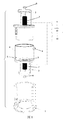
- FIG. 1 is an exploded view of the device for quickly matching wastewater and filler film according to the present invention
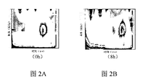
- 2A and 2B are signal spectra formed by the filler 1 after 0 hours and 8 hours, respectively;
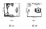
- 3A and 3B are signal spectra of the filler 2 formed after 0 hours and 8 hours, respectively.
- the biofilm method provides a new idea for upgrading the water plant, but in some water bodies, the biofilm is difficult to form on the surface of the filler.
- the existing technology is aimed at the unknown water body and a large number of fillers with different properties, which are time-consuming and labor-intensive. There is no method for rationalizing the application of existing resources, and therefore the present invention provides an apparatus and method for quickly matching wastewater and filler film.
- a device for quickly matching a waste water and a packing film comprising a cabin fixing base 1, a film forming monitoring chamber 4, an ultrasonic probe mounting chamber 2, an ultrasonic generator 9, an oscilloscope 10, and a control system 11,
- the cabin fixing base 1 is formed by a circular sheet-shaped base and a semi-open cylindrical fitting.
- the film forming monitoring chamber 4 is a transparent box body, and the inlet and outlet water device is installed on the side of the film forming monitoring chamber 4.
- the water inlet and outlet device comprises a water inlet 5 at the lower side of the side and a water outlet 6 at the upper side of the side surface, and the bottom of the film monitoring chamber 4 is formed.
- a groove is provided, and the diaphragm 3 used for monitoring is installed in the groove.
- An ultrasonic probe mounting chamber 2 is disposed above and below the film forming monitoring chamber 4, and an ultrasonic sensing probe 7 is disposed in the ultrasonic probe mounting chamber 2, and an ultrasonic probe mounting chamber disposed under the chamber fixing base 1 and below the film forming monitoring chamber 2
- the two ultrasonic sensing probes 7 are connected in series with the ultrasonic generator 9, the oscilloscope 10 and the control system 11.
- Film formation supervision The ultrasonic probe installation compartment 2 disposed above the cabin 4 is composed of a lower cylindrical fixture and an upper ultrasonic sensor fixed compartment.
- the ultrasonic sensor fixed compartment is provided with an ultrasonic fixing device, and the ultrasonic sensing probe 7 is installed from the side of the ultrasonic fixture.
- the lower cylindrical fixing frame Fixed by the rotating screw 8, the lower cylindrical fixing frame is provided with a plurality of notches corresponding to the positions of the water inlet 5 and the water outlet 6, respectively, and the ultrasonic detecting probe of the lower portion of the film forming monitoring chamber 4 is installed.
- An ultrasonic fixing device is disposed in the ultrasonic probe mounting chamber 2 of the bottom surface of the membrane monitoring chamber 4.
- the ultrasonic sensing probe 7 is mounted from the side of the ultrasonic fixing device and fixed by a rotating screw 8.
- the ultrasonic sensing probe 7 is applied to the side of the ultrasonic fixing device by applying a coupling agent and then rotating the screw 8.
- the device has the advantages of simple structure, convenient installation, convenient operation and high work efficiency;
- filtrate A The filtrate is divided into two parts, one part of the filtrate is labeled as filtrate A; the other part of the filtrate is filtered through another layer of 0.22 to 0.45 micron filter, and the filtrate is taken as filtrate B, which is the reference solution of filtrate A;
- the filtrate A is driven from the water inlet 5 through a peristaltic pump; the filtrate A enters a flow rate of 0.5 mL/min to 10 mL/min;
- the parameter selection range of the device 8 is a repetition frequency of 15 to 25 Hz, a pulse resistance of 30 to 60 ⁇ , a pulse voltage of 200 to 400 V, a gain of 60 dB, a high-pass filter of 0.03 to 0.1 MHz, and a low-pass filter of 1 to 3 MHz;
- the membrane 3 having the shortest biofilm formation time is selected as the membrane filler of the target water body, and the rapid matching process is completed. You can choose more fillers of different materials to repeat this process and choose a better filler.
- filtrate A The filtrate is divided into two parts, one part of the filtrate is labeled as filtrate A; the other part of the filtrate is filtered through a further 0.22 micron filter membrane, and the filtrate is taken, and labeled as filtrate B, which is the reference solution of filtrate A;
- the filtrate A is driven from the water inlet 5 through a peristaltic pump; the filtrate A enters a flow rate of 1 mL/min;
- the parameter selection range of the device 8 is a repetition frequency of 20 Hz, a pulse resistance of 30 ⁇ , a pulse voltage of 400 V, a gain of 60 dB, a high-pass filter of 0.03 MHz, and a low-pass filter of 1 MHz;
- the membrane 3 having the shortest biofilm formation time is selected as the membrane filler of the target water body, and the rapid matching process is completed.
- the preferred process is completed, that is, the filler 2 corresponding to the diaphragm 2 is suitable for the target water plant to hang the membrane.
- filtrate A one portion of the filtrate is labeled as filtrate A; the other portion of the filtrate is filtered through a further 0.45 micron filter membrane, and the filtrate is taken as filtrate B, which is the reference solution of filtrate A;
- the filtrate A is driven from the water inlet 5 through a peristaltic pump; the filtrate A enters a flow rate of 10 mL/min;
- the parameter selection range of the device 8 is a repetition frequency of 15 Hz, a pulse resistance of 60 ⁇ , a pulse voltage of 200 V, a gain of 60 dB, a high-pass filter of 0.1 MHz, and a low-pass filter of 3 MHz;
- the membrane 3 having the shortest biofilm formation time is selected as the membrane filler of the target water body, and the rapid matching process is completed.
- the filtrate A is driven from the water inlet 5 through a peristaltic pump; the filtrate A enters a flow rate of 0.5 mL/min;
- the parameter selection range of the device 8 is a repetition frequency of 25 Hz, a pulse resistance of 40 ⁇ , a pulse voltage of 300 V, a gain of 60 dB, a high-pass filter of 0.05 MHz, and a low-pass filter of 2 MHz;
- the membrane 3 having the shortest biofilm formation time is selected as the membrane filler of the target water body, and the rapid matching process is completed.
- the filtrate A is driven from the water inlet 5 through a peristaltic pump; the filtrate A enters a flow rate of 0.5 mL/min;
- the parameter selection range of the device 8 is a repetition frequency of 25 Hz, a pulse resistance of 40 ⁇ , a pulse voltage of 300 V, a gain of 60 dB, a high-pass filter of 0.05 MHz, and a low-pass filter of 2 MHz;
Landscapes
- Life Sciences & Earth Sciences (AREA)
- Biodiversity & Conservation Biology (AREA)
- Microbiology (AREA)
- Hydrology & Water Resources (AREA)
- Engineering & Computer Science (AREA)
- Environmental & Geological Engineering (AREA)
- Water Supply & Treatment (AREA)
- Chemical & Material Sciences (AREA)
- Organic Chemistry (AREA)
- Separation Using Semi-Permeable Membranes (AREA)
- Biological Treatment Of Waste Water (AREA)
Abstract
一种快速匹配废水和填料挂膜的装置及方法,属于生物膜污水处理领域技术。一种快速匹配废水和填料挂膜的装置,包括舱室固定底座(1)、成膜监测舱室(4)、超声探头安装舱室(2)、超声发生器(9)、示波器(10)和控制系统(11),成膜监测舱室(4)上方和下方分别设置有超声探头安装舱室(2),超声探头安装舱室(2)内设置有超声传感探头(7),舱室固定底座(1)上部与成膜监测舱室(4)下方设置的超声探头安装舱室(2)相连接;两个超声传感探头(7)与超声发生器(9)、示波器(10)和控制系统(11)依次连接。通过污泥预处理—安置膜片—超声在线监测成膜过程,选择成膜速度最快的填料作为目标填料,即完成匹配过程,能够最大程度上实现有效挂膜,缩短整体挂膜时间,将使用填料技术承担的风险最低化。
Description
本发明属于生物膜法污水处理技术领域,更具体地说,涉及一种快速匹配废水和填料挂膜的装置及方法。
在污水处理的二级生化处理系统中,活性污泥法和生物膜法占主导地位,生物膜法由于具有水量水质适应性强、对有机物的去除、脱氮除磷及去除重金属效果良好、动力费用省等优点,得到了广泛的关注和应用。生物膜主要由微生物细胞和它们所产物膜进行生长、成熟和老化的循环。生物膜的载体一般有软性填料、组合填料以及悬浮填料等。软性填料和组合填料由于其具有重量轻、比表面积大、空隙可变、不易堵塞、耐冲击负荷等效果稳定,且造价低、运输方便和组装简易等特点,被率先广泛应用于处理纺织、印染、酿酒、石油化工等工业和生活污水的处理中。但是在实际的废水挂膜过程中,由于水体复杂,污泥菌群组成差异大,导致同一性质的填料在不同的水体中挂膜性能差异明显。因此,对用于实际工程的填料长时间的小试挂膜试验或者直接投加填料进行挂膜不仅耗时耗力,而且很有可能会挂膜失败。因此,亟待开发有效快速的方法进行对挂膜水体匹配最优的挂膜填料,达到填料高速挂膜的目的。
中国专利申请号为CN101913710A,授权日期为2011年10月5日公开了一种悬浮填料微生物快速挂膜的方法,该方法其特征是首先将污泥取回后曝气48h,用曝气后的污泥做接种菌,接种于装有悬浮填料的序批式SBR反应器中,曝气6h,静置沉淀6h;然后投加营养基质,曝气l0h,静置沉淀2h作为一个运行周期,每天运行2个周期,期间进行排泥保持污泥悬浮固体浓度保持在2-20g/L范围内的某一浓度值不变;运行7-25d挂膜即完成。但此方法运行时间长,且损耗资源多。
中国专利申请号为CN105461083A,公开日期为2016年5月4日,该方法公开一种用于微生物快速挂膜的悬浮填料,所述悬浮填料由以下重量份的组分组成:高密度聚乙烯65~75份、熟石灰5~15份、陶氏粉末活性炭5~20份、轻质碳酸钙6~10份、马来酸酐3~5份、过氧化二异丙苯0.2~0.6份、明胶1.5~3份、甲壳素1~2份、四氧化三铁磁粉0.8~2份和锰锌铁氧体0.1~0.3份;所述用于微生物快速挂膜的悬浮填料的密度为0.96~0.98g/cm3。此填料使用窄,适用性不广泛。
目前针对快速挂膜的策略主要有两种,第一种即通过高污泥浓度情况下挂膜,且通过投
加外源物质进行强化挂膜;而第二种主要是通过对填料本身进行改性,让其更加适合于特定水体挂膜。然而,针对未知水体及大量各种不同性质的填料,这两种方式均属于耗时耗力且没有对现有资源合理化应用的方法。
发明内容
1.要解决的问题
针对大量未知水体挂膜困难的问题,本发明提供一种快速匹配废水和填料挂膜的装置及方法。本发明的方法能够最大程度上实现有效挂膜,缩短整体挂膜时间,将使用填料技术承担的风险最低化。
2.技术方案
为了解决上述问题,本发明所采用的技术方案如下:
一种快速匹配废水和填料挂膜的装置,包括舱室固定底座、成膜监测舱室、超声探头安装舱室、超声发生器、示波器和控制系统,成膜监测舱室上方和下方分别设置有超声探头安装舱室,超声探头安装舱室内设置有超声传感探头,舱室固定底座上部与成膜监测舱室下方设置的超声探头安装舱室相连接;两个超声传感探头与超声发生器、示波器和控制系统依次连接。
更进一步的,所述的舱室固定底座是由圆形片状底座和半开口的圆柱贴合形成。
更进一步的,所述的成膜监测舱室为透明箱体,成膜监测舱室侧面安装有进出水装置,进出水装置包括位于侧面下部的进水口和侧面上部的出水口,成膜监测舱室底部设置有凹槽,凹槽内安装监测使用的膜片。
更进一步的,成膜监测舱室上方设置的超声探头安装舱室是由下部的柱形固定架及上部的超声传感器固定舱室组成,超声传感器固定舱室内设置有超声固定装置,超声传感探头从超声固定装置侧面安装,通过旋转螺丝固定,下部的柱形固定架设置有若干槽口,槽口分别与进水口和出水口位置相对应,所述的成膜监测舱室下部超声探头安装舱室,成膜监测舱室底面超声探头安装舱室内设置有超声固定装置,超声传感探头从超声固定装置侧面安装,通过旋转螺丝固定。
更进一步的,超声传感探头涂抹耦合剂后通过旋转螺丝固定于超声固定装置侧面。可以更好的进行超声传感检测,提高精度,避免误差。
更进一步的,超声探头安装舱室底部设有环形凹槽及垫片,可通过凹槽使超声探头安装舱室与成膜监测舱室达到相对固定与密封。
一种快速匹配废水和填料挂膜的方法,其步骤为:
1)对目标挂膜泥水混合物进行采样,采用匀浆器进行匀浆;
2)将充分匀浆的泥水混合物用滤膜进行过滤,取滤液;
3)将滤液分为两份,一份滤液标记为滤液A;另一份滤液经过再一层滤膜过滤后取滤液,标记为滤液B,其为滤液A的参照溶液;
4)将膜片固定于成膜监测舱室内;
5)将快速匹配废水和填料挂膜装置组合完成;
6)将滤液A从进水口通过蠕动泵打入;
7)待滤液A上升直到从出水口流出时,开启超声发生器,开启超声反射模式,调整超声发生器参数到设定值,开启示波器,通过控制系统在线实时显示;
8)更换滤液A为滤液B,重复过程6)~7);
9)记录波形图上对应生物膜形成的时间;以备后期选择合适的时间作为填料;
10)更换膜片,重复过程5)~9),记录波形图上对应生物膜形成的时间;
11)根据10)的结果,选择形成生物膜时间最短的膜片对应填料作为目标水体的挂膜填料,完成快速匹配过程。
更进一步的,步骤1)的匀浆次数为10~15次。
更进一步的,步骤2)中采用泥水混合物用8~10微米滤膜进行过滤;步骤3)中采用另一份滤液经过0.22~0.45微米滤膜过滤后取滤液,标记为滤液B。
更进一步的,步骤6)滤液A进入流速为0.5mL/min~10mL/min。
更进一步的,步骤7)超声发射器的参数选择范围为重复频率15~25Hz,脉冲电阻30~60Ω,脉冲电压200~400V,增益60dB,高通滤波0.03~0.1MHz,低通滤波1~3MHz。
3.有益效果
相比于现有技术,本发明的有益效果为:
(1)本方案通过整体的装置系统,进行不同填料与不同水体的相互匹配,不用针对特殊水体开发专门的挂膜技术方案,通过匹配分方式选择合适的挂膜方案,选取快速,节约资源,避免其浪费;
(2)本发明的快速匹配废水和填料挂膜的装置由装置主体、装置内置柱体、超声传感器、信号发生器、示波器及控制系统组成,结构简单,方便安装,操作方便;
(3)通过成膜监测舱室为透明箱体和内部设置的超声探头安装舱室可以方便进行膜片的替换和超声传感器的替换,快速进行滤液与膜片的匹配,操作快捷,效率高;
(4)超声传感探头涂抹耦合剂后通过旋转螺丝固定于超声固定装置侧面,可以更好的进行超声传感检测,提高精度,避免误差;
(5)对于快速匹配废水和填料挂膜的方法,其主要步骤为:污泥预处理—安置膜片—超
声在线监测成膜过程,选择成膜速度最快的填料作为目标填料,即完成匹配过程,该发明从不同填料与不同水体的相互匹配入手,不用针对特殊水体开发专门的挂膜技术方案,避免资源浪费;监测装置属于在线实时、非接触式地直接进行无损监测,监测时间短,效率高、准确性好、成本低廉、操作安全;
(6)本发明的检测装置外部链接有示波器和控制系统,可以直观的观测到选择时候的数据,属于在线实时、非接触式地直接进行无损检测,检测时间短,效率高;
(7)本发明装置整体匹配的准确性好、成本低廉、操作安全,大尺度缩减不同填料在不同水体挂膜性能测试的空间及时间,为难挂膜水体提供了可靠的填料的优选方案。
图1为本发明的快速匹配废水和填料挂膜的装置分解图;
图2A和图2B为填料1分别在挂膜0小时和8小时后形成的信号图谱;
图3A和图3B为填料2分别在挂膜0小时和8小时后形成的信号图谱。
图中标号说明:
1、舱室固定底座;2、超声探头安装舱室;3、膜片;4、成膜监测舱室;5、进水口;6、出水口;7、超声传感探头;8、旋转螺丝;9、超声发生器;10、示波器;11、控制系统。
下面结合具体实施例对本发明进一步进行描述。
由于我国需要对水厂出水水质进行提标,进而大量水厂面临升级改造的难题。生物膜法为水厂升级改造提供新的思路,但是在某些水体中生物膜很难在填料表面形成,现有的技术针对未知水体及大量各种不同性质的填料,均属于耗时耗力且没有对现有资源合理化应用的方法,因此本发明提供了一种快速匹配废水和填料挂膜的装置及方法。
实施例
如图1所示,一种快速匹配废水和填料挂膜的装置,包括舱室固定底座1、成膜监测舱室4、超声探头安装舱室2、超声发生器9、示波器10和控制系统11,所述的舱室固定底座1是由圆形片状底座和半开口的圆柱贴合形成。
所述的成膜监测舱室4为透明箱体,成膜监测舱室4侧面安装有进出水装置,进出水装置包括位于侧面下部的进水口5和侧面上部的出水口6,成膜监测舱室4底部设置有凹槽,凹槽内安装监测使用的膜片3。
成膜监测舱室4上方和下方分别设置有超声探头安装舱室2,超声探头安装舱室2内设置有超声传感探头7,舱室固定底座1上部与成膜监测舱室4下方设置的超声探头安装舱室2相连接;两个超声传感探头7与超声发生器9、示波器10和控制系统11依次连接。成膜监
测舱室4上方设置的超声探头安装舱室2是由下部的柱形固定架及上部的超声传感器固定舱室组成,超声传感器固定舱室内设置有超声固定装置,超声传感探头7从超声固定装置侧面安装,通过旋转螺丝8固定,下部的柱形固定架设置有若干槽口,槽口分别与进水口5和出水口6位置相对应,所述的成膜监测舱室4下部超声探头安装舱室2,成膜监测舱室4底面超声探头安装舱室2内设置有超声固定装置,超声传感探头7从超声固定装置侧面安装,通过旋转螺丝8固定。超声传感探头7涂抹耦合剂后通过旋转螺丝8固定于超声固定装置侧面。本装置的结构简单,方便安装,操作方便,工作效率高;
对应使用上述超声装置的一种快速匹配废水和填料挂膜的方法,其步骤为:
1)对目标挂膜泥水混合物进行采样,采用匀浆器进行匀浆;匀浆次数为10~15次。
2)将充分匀浆的泥水混合物用8~10微米滤膜进行过滤,取滤液;
3)将滤液分为两份,一份滤液标记为滤液A;另一份滤液经过再一层0.22~0.45微米滤膜过滤后取滤液,标记为滤液B,其为滤液A的参照溶液;
4)将膜片3固定于成膜监测舱室4内;
5)将快速匹配废水和填料挂膜装置组合完成;
6)将滤液A从进水口5通过蠕动泵打入;滤液A进入流速为0.5mL/min~10mL/min;
7)待滤液A上升直到从出水口6流出时,开启超声发生器9,开启超声反射模式,调整超声发生器9参数到设定值,开启示波器10,通过控制系统11在线实时显示;超声发射器8的参数选择范围为重复频率15~25Hz,脉冲电阻30~60Ω,脉冲电压200~400V,增益60dB,高通滤波0.03~0.1MHz,低通滤波1~3MHz;
8)更换滤液A为滤液B,重复过程6)~7);
9)记录波形图上对应生物膜形成的时间;
10)更换膜片3,重复过程5)~9),记录波形图上对应生物膜形成的时间;
11)根据10)的结果,选择形成生物膜时间最短的膜片3对应填料作为目标水体的挂膜填料,完成快速匹配过程。可以选择更多不同材质的填料重复这个过程,选择更加优秀的填料。
实施例1
某工业废水存在出水水质不能满足一级(A)的要求,拟采用生物膜法对原有的好氧池进行升级改造。
本实例的具体实施过程为:
1)对目标挂膜泥水混合物进行采样,采用匀浆器进行匀浆;匀浆次数为15次。
2)将充分匀浆的泥水混合物用10微米滤膜进行过滤,取滤液;
3)将滤液分为两份,一份滤液标记为滤液A;另一份滤液经过再一层0.22微米滤膜过滤后取滤液,标记为滤液B,其为滤液A的参照溶液;
4)将1号膜片3固定于成膜监测舱室4内;
5)将快速匹配废水和填料挂膜装置组合完成;
6)将滤液A从进水口5通过蠕动泵打入;滤液A进入流速为1mL/min;
7)待滤液A上升直到从出水口6流出时,开启超声发生器9,开启超声反射模式,调整超声发生器9参数到设定值,开启示波器10,通过控制系统11在线实时显示;超声发射器8的参数选择范围为重复频率20Hz,脉冲电阻30Ω,脉冲电压400V,增益60dB,高通滤波0.03MHz,低通滤波1MHz;
8)记录波形图上对应生物膜形成的时间;
9)更换2号膜片3,重复过程5)~8),记录波形图上对应生物膜形成的时间;
10)根据9)的结果,选择形成生物膜时间最短的膜片3对应填料作为目标水体的挂膜填料,完成快速匹配过程。如图2-图3所示,我们可以发现除了在0.45μs处无机盐沉积层和0.85μs处的填料的反射信号,图3中在8h时,在0.1μs处已经率先形成了生物膜的反射信号。经过上述步骤完成优选过程,即膜片2对应的填料2适合于目标水厂挂膜。
实施例2
某工业废水存在出水水质不能满足一级(A)的要求,拟采用生物膜法对原有的好氧池进行升级改造。
本实例的具体实施过程为:
1)对目标挂膜泥水混合物进行采样,采用匀浆器进行匀浆;匀浆次数为10次。
2)将充分匀浆的泥水混合物用8微米滤膜进行过滤,取滤液;
3)将滤液分为两份,一份滤液标记为滤液A;另一份滤液经过再一层0.45微米滤膜过滤后取滤液,标记为滤液B,其为滤液A的参照溶液;
4)将1号膜片3固定于成膜监测舱室4内;
5)将快速匹配废水和填料挂膜装置组合完成;
6)将滤液A从进水口5通过蠕动泵打入;滤液A进入流速为10mL/min;
7)待滤液A上升直到从出水口6流出时,开启超声发生器9,开启超声反射模式,调整超声发生器9参数到设定值,开启示波器10,通过控制系统11在线实时显示;超声发射器8的参数选择范围为重复频率15Hz,脉冲电阻60Ω,脉冲电压200V,增益60dB,高通滤波0.1MHz,低通滤波3MHz;
8)记录波形图上对应生物膜形成的时间;
9)更换2号膜片3,重复过程5)~8),记录波形图上对应生物膜形成的时间;
10)根据9)的结果,选择形成生物膜时间最短的膜片3对应填料作为目标水体的挂膜填料,完成快速匹配过程。
实施例3
某工业废水存在出水水质不能满足一级(A)的要求,拟采用生物膜法对原有的好氧池进行升级改造。
本实例的具体实施过程为:
1)对目标挂膜泥水混合物进行采样,采用匀浆器进行匀浆;匀浆次数为12次。
2)将充分匀浆的泥水混合物用9微米滤膜进行过滤,取滤液;
3)将滤液分为两份,一份滤液标记为滤液A;另一份滤液经过再一层0.3微米滤膜过滤后取滤液,标记为滤液B,其为滤液A的参照溶液;
4)将1号膜片3固定于成膜监测舱室4内;
5)将快速匹配废水和填料挂膜装置组合完成;
6)将滤液A从进水口5通过蠕动泵打入;滤液A进入流速为0.5mL/min;
7)待滤液A上升直到从出水口6流出时,开启超声发生器9,开启超声反射模式,调整超声发生器9参数到设定值,开启示波器10,通过控制系统11在线实时显示;超声发射器8的参数选择范围为重复频率25Hz,脉冲电阻40Ω,脉冲电压300V,增益60dB,高通滤波0.05MHz,低通滤波2MHz;
8)记录波形图上对应生物膜形成的时间;
9)更换2号膜片3,重复过程5)~8),记录波形图上对应生物膜形成的时间;
10)根据9)的结果,选择形成生物膜时间最短的膜片3对应填料作为目标水体的挂膜填料,完成快速匹配过程。
实施例4
某工业废水存在出水水质不能满足一级(A)的要求,拟采用生物膜法对原有的好氧池进行升级改造。
本实例的具体实施过程为:
1)对目标挂膜泥水混合物进行采样,采用匀浆器进行匀浆;匀浆次数为12次。
2)将充分匀浆的泥水混合物用9微米滤膜进行过滤,取滤液;
3)将滤液分为两份,一份滤液标记为滤液A;另一份滤液经过再一层0.3微米滤膜过滤后取滤液,标记为滤液B,其为滤液A的参照溶液;
4)将1号膜片3固定于成膜监测舱室4内;
5)将快速匹配废水和填料挂膜装置组合完成;
6)将滤液A从进水口5通过蠕动泵打入;滤液A进入流速为0.5mL/min;
7)待滤液A上升直到从出水口6流出时,开启超声发生器9,开启超声反射模式,调整超声发生器9参数到设定值,开启示波器10,通过控制系统11在线实时显示;超声发射器8的参数选择范围为重复频率25Hz,脉冲电阻40Ω,脉冲电压300V,增益60dB,高通滤波0.05MHz,低通滤波2MHz;
8)记录波形图上对应生物膜形成的时间;
9)更换滤液B,重复过程5)~8),记录波形图上对应生物膜形成的时间;
10)根据9)的结果,作出对比,反映出滤液A贴近于原有污水获得的挂膜填料特性。
值得说明的是,对于本领域技术人员来说,在本发明构思及具体实施例启示下,能够从本发明公开内容及常识直接导出或联想到的一些变形。本领域普通技术人员将意识到也可采用其他方法,或现有技术中常用公知技术的替代,以及特征间的相互不同组合等等的非实质性改动,同样可以被应用,都能实现本发明描述的功能和效果,不再一一举例展开细说,均属于本发明保护范围。
Claims (15)
- 一种快速匹配废水和填料挂膜的装置,其特征在于:包括舱室固定底座(1)、成膜监测舱室(4)、超声探头安装舱室(2)、超声发生器(9)、示波器(10)和控制系统(11),成膜监测舱室(4)上方和下方分别设置有超声探头安装舱室(2),超声探头安装舱室(2)内设置有超声传感探头(7),舱室固定底座(1)上部与成膜监测舱室(4)下方设置的超声探头安装舱室(2)相连接;两个超声传感探头(7)与超声发生器(9)、示波器(10)和控制系统(11)依次连接。
- 根据权利要求1所述的一种快速匹配废水和填料挂膜的装置,其特征在于:所述的舱室固定底座(1)是由圆形片状底座和半开口的圆柱贴合形成。
- 根据权利要求1所述的一种快速匹配废水和填料挂膜的装置,其特征在于:所述的成膜监测舱室(4)为透明箱体,成膜监测舱室(4)侧面安装有进出水装置,进出水装置包括位于侧面下部的进水口(5)和侧面上部的出水口(6),成膜监测舱室(4)底部设置有凹槽,凹槽内安装监测使用的膜片(3)。
- 根据权利要求2所述的一种快速匹配废水和填料挂膜的装置,其特征在于:所述的成膜监测舱室(4)为透明箱体,成膜监测舱室(4)侧面安装有进出水装置,进出水装置包括位于侧面下部的进水口(5)和侧面上部的出水口(6),成膜监测舱室(4)底部设置有凹槽,凹槽内安装监测使用的膜片(3)。
- 根据权利要求3所述的一种快速匹配废水和填料挂膜的装置,其特征在于:成膜监测舱室(4)上方设置的超声探头安装舱室(2)是由下部的柱形固定架及上部的超声传感器固定舱室组成,超声传感器固定舱室内设置有超声固定装置,超声传感探头(7)从超声固定装置侧面安装,通过旋转螺丝(8)固定,下部的柱形固定架设置有若干槽口,槽口分别与进水口(5)和出水口(6)位置相对应,所述的成膜监测舱室(4)下部超声探头安装舱室(2),成膜监测舱室(4)底面超声探头安装舱室(2)内设置有超声固定装置,超声传感探头(7)从超声固定装置侧面安装,通过旋转螺丝(8)固定。
- 根据权利要求4所述的一种快速匹配废水和填料挂膜的装置,其特征在于:成膜监测舱室(4)上方设置的超声探头安装舱室(2)是由下部的柱形固定架及上部的超声传感器固定舱室组成,超声传感器固定舱室内设置有超声固定装置,超声传感探头(7)从超声固定装置侧面安装,通过旋转螺丝(8)固定,下部的柱形固定架设置有若干槽口,槽口分别与进水口(5)和出水口(6)位置相对应,所述的成膜监测舱室(4)下部超声探头安装舱室(2),成膜监测舱室(4)底面超声探头安装舱室(2)内设置有超声固定装置,超声传感探头(7)从超声固定装置侧面安装,通过旋转螺丝(8)固定。
- 根据权利要求5所述的一种快速匹配废水和填料挂膜的装置,其特征在于:超声传感 探头(7)涂抹耦合剂后通过旋转螺丝(8)固定于超声固定装置侧面。
- 根据权利要求6所述的一种快速匹配废水和填料挂膜的装置,其特征在于:超声传感探头(7)涂抹耦合剂后通过旋转螺丝(8)固定于超声固定装置侧面。
- 根据权利要求5所述的一种快速匹配废水和填料挂膜的装置,其特征在于:超声探头安装舱室(2)底部设有环形凹槽及垫片,可通过凹槽使超声探头安装舱室(2)与成膜监测舱室(4)相对固定与密封。
- 根据权利要求6所述的一种快速匹配废水和填料挂膜的装置,其特征在于:超声探头安装舱室(2)底部设有环形凹槽及垫片,可通过凹槽使超声探头安装舱室(2)与成膜监测舱室(4)相对固定与密封。
- 一种快速匹配废水和填料挂膜的方法,其步骤为:1)对目标挂膜泥水混合物进行采样,采用匀浆器进行匀浆;2)将充分匀浆的泥水混合物用滤膜进行过滤,取滤液;3)将滤液分为两份,一份滤液标记为滤液A;另一份滤液经过再一层滤膜过滤后取滤液,标记为滤液B,其为滤液A的参照溶液;4)将膜片(3)固定于成膜监测舱室(4)内;5)将快速匹配废水和填料挂膜装置组合完成;6)将滤液A从进水口(5)通过蠕动泵打入;7)待滤液A上升直到从出水口(6)流出时,开启超声发生器(9),开启超声反射模式,调整超声发生器(9)参数到设定值,开启示波器(10),通过控制系统(11)在线实时显示;8)更换滤液A为滤液B,重复过程6)~7);9)记录波形图上对应生物膜形成的时间;10)更换膜片(3),重复过程5)~9),记录波形图上对应生物膜形成的时间;11)根据10)的结果,选择形成生物膜时间最短的膜片(3)对应填料作为目标水体的挂膜填料,完成快速匹配过程。
- 根据权利要求11所述的一种快速匹配废水和填料挂膜的方法,其特征在于:步骤1)的匀浆次数为10~15次。
- 根据权利要求11所述的一种快速匹配废水和填料挂膜的方法,其特征在于:步骤2)中采用泥水混合物用8~10微米滤膜进行过滤;步骤3)中采用另一份滤液经过0.22~0.45微米滤膜过滤后取滤液,标记为滤液B。
- 根据权利要求11所述的一种快速匹配废水和填料挂膜的方法,其特征在于:步骤6)滤液A进入流速为0.5mL/min~10mL/min。
- 根据权利要求11所述的一种快速匹配废水和填料挂膜的方法,其特征在于:步骤7)超声发射器(8)的参数选择范围为重复频率15~25Hz,脉冲电阻30~60Ω,脉冲电压200~400V,增益60dB,高通滤波0.03~0.1MHz,低通滤波1~3MHz。
Priority Applications (1)
| Application Number | Priority Date | Filing Date | Title |
|---|---|---|---|
| US15/871,145 US10712315B2 (en) | 2016-11-09 | 2018-01-15 | Device and method for supervising biofilm culturing |
Applications Claiming Priority (2)
| Application Number | Priority Date | Filing Date | Title |
|---|---|---|---|
| CN201610984895.6 | 2016-11-09 | ||
| CN201610984895.6A CN106336004B (zh) | 2016-11-09 | 2016-11-09 | 一种快速匹配废水和填料挂膜的装置及方法 |
Related Child Applications (1)
| Application Number | Title | Priority Date | Filing Date |
|---|---|---|---|
| US15/871,145 Continuation-In-Part US10712315B2 (en) | 2016-11-09 | 2018-01-15 | Device and method for supervising biofilm culturing |
Publications (1)
| Publication Number | Publication Date |
|---|---|
| WO2018086389A1 true WO2018086389A1 (zh) | 2018-05-17 |
Family
ID=57841064
Family Applications (1)
| Application Number | Title | Priority Date | Filing Date |
|---|---|---|---|
| PCT/CN2017/095850 Ceased WO2018086389A1 (zh) | 2016-11-09 | 2017-08-03 | 一种快速匹配废水和填料挂膜的装置及方法 |
Country Status (2)
| Country | Link |
|---|---|
| CN (1) | CN106336004B (zh) |
| WO (1) | WO2018086389A1 (zh) |
Families Citing this family (4)
| Publication number | Priority date | Publication date | Assignee | Title |
|---|---|---|---|---|
| CN106336004B (zh) * | 2016-11-09 | 2019-08-09 | 南京大学 | 一种快速匹配废水和填料挂膜的装置及方法 |
| CN109489568B (zh) * | 2018-09-30 | 2019-10-08 | 南京大学 | 一种在线测定废水处理填料生物膜厚度的辅助装置及测定方法 |
| CN113189197A (zh) * | 2021-04-29 | 2021-07-30 | 南京大学 | 一种原位监测活性污泥沉降性能的装置及检测方法 |
| CN114317259B (zh) | 2022-03-15 | 2022-07-01 | 南方海洋科学与工程广东省实验室(广州) | 深海冷泉区膜生物反应器及在线式环境参数测量系统 |
Citations (6)
| Publication number | Priority date | Publication date | Assignee | Title |
|---|---|---|---|---|
| US5641642A (en) * | 1995-09-26 | 1997-06-24 | Battelle Memorial Institute | In situ biofilm coupon device |
| US7485224B2 (en) * | 2006-03-03 | 2009-02-03 | Sam Houston State University | Mobile bioremediation systems |
| CN103472217A (zh) * | 2013-09-10 | 2013-12-25 | 金贝尔(福建)水环境工程有限公司 | 多种生物填料氨氮去除特性快速评价方法及装置 |
| CN104211174A (zh) * | 2014-09-09 | 2014-12-17 | 江苏科技大学 | 一种生物膜反应装置及生物膜反应系统 |
| CN105174494A (zh) * | 2015-10-19 | 2015-12-23 | 浙江省农业科学院 | 污水处理用高效挂膜填料系统和挂膜方法 |
| CN106336004A (zh) * | 2016-11-09 | 2017-01-18 | 南京大学 | 一种快速匹配废水和填料挂膜的装置及方法 |
Family Cites Families (5)
| Publication number | Priority date | Publication date | Assignee | Title |
|---|---|---|---|---|
| GB1442454A (en) * | 1972-08-18 | 1976-07-14 | Kreuter J | Sewage treatment processes and apparatus |
| CN104591372A (zh) * | 2015-02-09 | 2015-05-06 | 江苏裕隆环保有限公司 | 一种悬浮活性生物填料活化再生的方法和装置 |
| CN105152306A (zh) * | 2015-08-31 | 2015-12-16 | 南京大学 | 一种异位去除制药工业废水悬浮填料老化生物膜的方法 |
| CN205313167U (zh) * | 2016-01-21 | 2016-06-15 | 上海方合正环境工程科技发展有限公司 | 生态挂膜 |
| CN105668773A (zh) * | 2016-01-27 | 2016-06-15 | 苏州科环环保科技有限公司 | 微生物快速挂膜用悬浮填料的制备工艺 |
-
2016
- 2016-11-09 CN CN201610984895.6A patent/CN106336004B/zh active Active
-
2017
- 2017-08-03 WO PCT/CN2017/095850 patent/WO2018086389A1/zh not_active Ceased
Patent Citations (6)
| Publication number | Priority date | Publication date | Assignee | Title |
|---|---|---|---|---|
| US5641642A (en) * | 1995-09-26 | 1997-06-24 | Battelle Memorial Institute | In situ biofilm coupon device |
| US7485224B2 (en) * | 2006-03-03 | 2009-02-03 | Sam Houston State University | Mobile bioremediation systems |
| CN103472217A (zh) * | 2013-09-10 | 2013-12-25 | 金贝尔(福建)水环境工程有限公司 | 多种生物填料氨氮去除特性快速评价方法及装置 |
| CN104211174A (zh) * | 2014-09-09 | 2014-12-17 | 江苏科技大学 | 一种生物膜反应装置及生物膜反应系统 |
| CN105174494A (zh) * | 2015-10-19 | 2015-12-23 | 浙江省农业科学院 | 污水处理用高效挂膜填料系统和挂膜方法 |
| CN106336004A (zh) * | 2016-11-09 | 2017-01-18 | 南京大学 | 一种快速匹配废水和填料挂膜的装置及方法 |
Also Published As
| Publication number | Publication date |
|---|---|
| CN106336004A (zh) | 2017-01-18 |
| CN106336004B (zh) | 2019-08-09 |
Similar Documents
| Publication | Publication Date | Title |
|---|---|---|
| WO2018086389A1 (zh) | 一种快速匹配废水和填料挂膜的装置及方法 | |
| CN101759290B (zh) | 连续流工艺中快速实现并稳定维持短程硝化的方法 | |
| CN106430662A (zh) | 一种曝气控制系统及方法 | |
| CN103880263B (zh) | 一种适用于剩余污泥厌氧消化的动态膜形成控制方法 | |
| CN118026314B (zh) | 一种高效节能抗老化的污水处理用反应器 | |
| CN106989956B (zh) | 一种浅水海域含沙水体原位自动采集装置及方法 | |
| CN109775845B (zh) | 污水处理中的曝氧量控制方法与装置 | |
| CN103342415B (zh) | 城市污水厂进水毒性监测装置 | |
| CN103336028B (zh) | 一种城市污水厂进水毒性监测方法 | |
| CN206783390U (zh) | 一种曝气生物滤池的自动检测与控制装置 | |
| CN105645571A (zh) | 一种用作曝气生物滤池填料的改性牡蛎壳的制备方法 | |
| CN1446901A (zh) | 酶反应控制装置 | |
| CN110950498B (zh) | 一种变频直流旁位水处理一体化设备 | |
| CN107117703A (zh) | 一种实时控制序批式膜生物反应器 | |
| CN107857436A (zh) | 基于物联网的生物化学絮凝吸附污水处理控制系统 | |
| CN112811580A (zh) | 一种快速匹配废水与信号分子调控生物膜挂膜的方法 | |
| CN220583522U (zh) | 一种污水处理系统气体排放通量的测量系统 | |
| CN218298173U (zh) | 一种生物污损动态模拟实验装置 | |
| CN215506369U (zh) | 一种用于管式膜系统在线监测污泥浓度动态排泥装置 | |
| CN210347625U (zh) | 一种高效氟硼酸钾合成废水监控装置 | |
| CN207650198U (zh) | 一种水质检测装置 | |
| CN210109108U (zh) | 一种新型连续间歇式污泥耗氧呼吸速率测定装置 | |
| CN201226000Y (zh) | 研究污水脱氮过程中n2o产生的设备 | |
| CN214976078U (zh) | 一种净化mbr膜的设备 | |
| CN106630140A (zh) | 一种源头富集与回收污水有机碳源的方法及装置 |
Legal Events
| Date | Code | Title | Description |
|---|---|---|---|
| 121 | Ep: the epo has been informed by wipo that ep was designated in this application |
Ref document number: 17869624 Country of ref document: EP Kind code of ref document: A1 |
|
| NENP | Non-entry into the national phase |
Ref country code: DE |
|
| 122 | Ep: pct application non-entry in european phase |
Ref document number: 17869624 Country of ref document: EP Kind code of ref document: A1 |