WO2018084237A1 - A busbar unit for an electric motor - Google Patents
A busbar unit for an electric motor Download PDFInfo
- Publication number
- WO2018084237A1 WO2018084237A1 PCT/JP2017/039712 JP2017039712W WO2018084237A1 WO 2018084237 A1 WO2018084237 A1 WO 2018084237A1 JP 2017039712 W JP2017039712 W JP 2017039712W WO 2018084237 A1 WO2018084237 A1 WO 2018084237A1
- Authority
- WO
- WIPO (PCT)
- Prior art keywords
- busbar
- connection terminal
- power source
- terminal portion
- source connection
- Prior art date
- Legal status (The legal status is an assumption and is not a legal conclusion. Google has not performed a legal analysis and makes no representation as to the accuracy of the status listed.)
- Ceased
Links
Images



Classifications
-
- H—ELECTRICITY
- H02—GENERATION; CONVERSION OR DISTRIBUTION OF ELECTRIC POWER
- H02K—DYNAMO-ELECTRIC MACHINES
- H02K3/00—Details of windings
- H02K3/46—Fastening of windings on the stator or rotor structure
- H02K3/50—Fastening of winding heads, equalising connectors, or connections thereto
-
- H—ELECTRICITY
- H02—GENERATION; CONVERSION OR DISTRIBUTION OF ELECTRIC POWER
- H02K—DYNAMO-ELECTRIC MACHINES
- H02K3/00—Details of windings
- H02K3/46—Fastening of windings on the stator or rotor structure
- H02K3/52—Fastening salient pole windings or connections thereto
- H02K3/521—Fastening salient pole windings or connections thereto applicable to stators only
- H02K3/522—Fastening salient pole windings or connections thereto applicable to stators only for generally annular cores with salient poles
-
- H—ELECTRICITY
- H01—ELECTRIC ELEMENTS
- H01R—ELECTRICALLY-CONDUCTIVE CONNECTIONS; STRUCTURAL ASSOCIATIONS OF A PLURALITY OF MUTUALLY-INSULATED ELECTRICAL CONNECTING ELEMENTS; COUPLING DEVICES; CURRENT COLLECTORS
- H01R25/00—Coupling parts adapted for simultaneous co-operation with two or more identical counterparts, e.g. for distributing energy to two or more circuits
- H01R25/16—Rails or bus-bars provided with a plurality of discrete connecting locations for counterparts
- H01R25/165—Connecting locations formed by surface mounted apparatus
-
- H—ELECTRICITY
- H02—GENERATION; CONVERSION OR DISTRIBUTION OF ELECTRIC POWER
- H02K—DYNAMO-ELECTRIC MACHINES
- H02K2203/00—Specific aspects not provided for in the other groups of this subclass relating to the windings
- H02K2203/09—Machines characterised by wiring elements other than wires, e.g. bus rings, for connecting the winding terminations
-
- H—ELECTRICITY
- H02—GENERATION; CONVERSION OR DISTRIBUTION OF ELECTRIC POWER
- H02K—DYNAMO-ELECTRIC MACHINES
- H02K2213/00—Specific aspects, not otherwise provided for and not covered by codes H02K2201/00 - H02K2211/00
- H02K2213/03—Machines characterised by numerical values, ranges, mathematical expressions or similar information
Definitions
- Various embodiments relate generally to a busbar unit for an electric motor and to an electric motor including a busbar unit.
- Electric motors have become essential parts in a large variety of driving systems employed, e.g., in mobile environments such as in vehicles.
- the operation of electric motors is usually controlled by an electronic control circuit electrically connected to the electric motor via a busbar unit.
- Typical electronic control circuits include a plurality of electronic components that are highly sensitive to mechanical stress that may occur during the coupling of the electronic control circuit to the busbar unit. An excessive mechanical stress exerted onto such an electronic control circuit may damage the sensitive components thereof leading to increased manufacturing costs.
- an object of the present invention is the provision of a busbar unit for an electric motor configured to enable a coupling to an electronic control circuit without exerting an excessive mechanical stress thereon.
- FIG. 1 shows a schematic view of an electric motor.
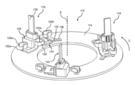
- FIG. 2 shows a perspective view of a busbar unit.
- FIG. 3 shows a plan view of a busbar of the busbar unit depicted in FIG. 2.
- FIG. 4 is a cross-sectional view of a part of the busbar unit shown in FIG. 2.
- FIG. 5 is a cross-sectional view perpendicular to the one shown in FIG. 4 of a part of the busbar unit shown in FIG. 2.
- FIG. 6 shows a portion of a busbar holder of the busbar unit depicted in FIG. 2.
- FIG. 1 shows a schemativ view of an electric motor 100 that may be employed in a hydraulic pump configured, e.g., to convey a service liquid in a vehicle such as lubricating oil or a coolant, e.g., cooling water.
- the electric motor 100 may include a housing 102, and a stator 104 fixedly mounted inside of the housing 102 and configured to generate a time-varying magnetic field by means of a plurality of coils 106.
- the stator 104 may have a basically annular shape centered around a central axis A’.
- the power source connection terminal portion 128 may be connected to a power source directly or indirectly by means of an electronic control circuit that controls the electric voltage and/or current supplied to an individual coil 106 or to a group of serially connected coils 106 of the electric motor 100 to generate the time-varying magnetic field required for a rotation of the rotor.
- the power source connection terminal portion 128 may extend from the base portion 122 and the base portion 122 may include a resilient member 130 that is configured to allow a displacement of the power source connection terminal portion 128 towards the busbar holder 114 under the influence of a force exerted onto the power source connection terminal portion towards the busbar holder 114.
- the resilient member 130 may be an intergral part of the base portion 122 and may be defined as that portion thereof that is deflectable under the influence of a force exerted onto the power source connection terminal portion 128 directed towards the busbar holder 114.
- the mechanical stress exerted onto an electronic control circuit during the coupling thereof to the power source connection terminal portion 128 can be reduced as compared to a power source connection terminal portion that is not configured to be displaced towards the busbar holder 114 under the influence of a force directed towards the busbar holder 114. In this way, the risk of damaging the electronic control circuit can be reduced.
- the power source connection terminal portion 128 may include a stopping member 140 and the supporting portion 138 may include a contacting portion 142 for the stopping member 140 that is configured to limit a displacement of the power source connection terminal portion 128 in a direction facing away from the recessed surface 134.
- the stopping member 140 an excessive deformation of the resilient member 130 can be avoided when disconnecting an electronic control circuit from the power source connection terminal portion 128.
- the stopping member 140 may be integrally formed with the power source connection terminal portion 128, e.g., as a portion stamped out thereof. Consequently, a power source connection terminal portion 128 with a simple structure may be provided in this way.
- the stopping member 140 may be configured as a resilient protrusion biased towards the supporting portion 138.
- the supporting portion 138 may surround at least a part of the circumference of the power source connection terminal portion 128 in order to keep the busbar 116 in a defined position on the busbar holder 114.
- the supporting portion 138 may include an inner circumference 144 complementary to an outer circumference of the part of the power source connection terminal portion 128 surrounded by the supporting portion 138. In this way, a defined position of the busbar 116 relative to the busbar holder 114 may be maintained which in turn reduces the mechanical stress exerted onto an electronic control circuit electrically connected to the busbar 116.
- the supporting portion 138 may include a slot 146 having a width W1 that is larger than the width of the second section 130b of the resilient member 130.
- the power source connection terminal portion 128 may be attached to the supporting portion 138 by inserting the power source connection terminal portion 128 into the supporting portion 138 and by passing the second portion 130b of the resilient member 130 through the slot 146.
- the stopping member 140 of the power source connection terminal portion 128 is configured as a resilient protrusion, it can be deflected towards the power source connection terminal portion 128 by the contacting portion 142 in the course of the above-described insertion movement and can pass by the contacting portion 142. After having passed the contacting portion 142, the stopping member 140 returns to its initial undeflected position shown in FIG. 5, i.e. it takes a position in which it inhibits a movement of the power source connection terminal portion 128 in a direction facing away from the busbar holder 114.
- At least the part of the power source connection terminal portion 128 surrounded by the supporting portion 138 may have a width W3 that is larger than the width W1 of the slot 146 and larger than the width W2 of the second portion 130b of the resilient member 130.
- the supporting portion 138 may include an abutment surface 148 facing towards an end surface 150 of the power source connection terminal portion 128 and may be configured to be brought into physical contact thereto upon applying a force onto the power source connection terminal portion 128 in a direction facing towards the busbar holder 114. Consequently, the abutment surface 148 may be configured as a stopper.
- At least one coil connection terminal portion 126a, 126b may be configured or may include a U-shaped or V-shaped crimp connector configured to be crimped around an end portion 107 of a winding wire of a coil 106 of the stator 104.
- the coils 106 of the stator 104 may be electrically connected to the busbar 116 simply by mechanically deforming the respective coil connection terminal portions 126a, 126b, meaning that no additional connection means are required for the connection thereof to the end portions 107 of the winding wires. In this way, a simple overall setup may be provided.
- the busbar holder 114 may include through holes 152a, 152b extending in the axial direction A of the busbar holder 114 and positioned in an overlapping relationship to the coil connection terminal portions 126a, 126b.
- through holes 152a, 152b end portions 107 of winding wires of the coils 106 may be simply passed through the busbar holder 114 to electrically connect them to the respective coil connection terminal portions 126a, 126b.
- the coil connection terminal portions 126a, 126b may be connected to the coils 106 of the stator 104 prior to connecting a power source or an electronic control circuit to the power source connection terminal portion 128.
- a force is applied onto the power source connection terminal portion 128 that leads to a deflection of the resilient member 130.
- Such a deflection of the resilient member 130 may have an impact on the connection between a coil connection terminal portion 126a, 126b and a respective end portion 107 of a winding wire of a coil 106 that may unintentionally increase the contact resistance therebetween.
- the base portion 122 of the busbar 116 may be provided with a cut-out coupling portion 154 between one coil connection terminal portion 126b and the resilient member 130.
- a deflection of parts of the busbar 116 different from the resilient member 130 may be additionally restricted by a protruding portion 156 extending along the mounting surface 124 in a direction facing away from the resilient member 130.
- the protruding portion 156 may be additionally utilized as a hot stacking means for positioning the busbar 116 on the busbar holder 114 in a defined manner.
- the busbar 116 may further include a resilient decoupling member 158 between the coil connection terminal portions 126a, 126b that may further contribute to a mechanical decoupling of the coil connection terminal portions 126a, 126b from each other.
- Example 1 is a busbar unit for an electric motor.
- the busbar unit may include a busbar holder at least a part of which is made of an electrically insulating material, and at least one busbar mounted on the busbar holder.
- the busbar may include a base portion extending along a mounting surface of the busbar holder, at least one coil connection terminal portion configured to be electrically connected to a coil of the electric motor, and a power source connection terminal portion configured to be electrically connected to a power source.
- the power source connection terminal portion may extend from the base portion and at least a part of the base portion may include a resilient member that is configured to allow a displacement of the power source connection terminal portion towards the busbar holder.
- Example 3 the subject matter of any one of Examples 1 or 2 can optionally further include that the busbar holder further includes a busbar contacting surface and a recessed surface which is recessed with respect to the busbar contacting surface.
- the resilient member may include a first section arranged on the busbar contacting surface and a second section extending along the recessed surface of the busbar holder.
- the power source connection terminal portion may extend from one end of the second section and the first section may extend from the other end of the second section.
- Example 7 the subject matter of Example 6 can optionally further include at least one stopping member provided on the power source connection terminal portion, and a contacting portion for the stopping member on the supporting portion.
- the stopping member may be configured to limit a displacement of the power source connection terminal portion in a direction facing away from the recessed surface by means of the contacting portion for the stopping member.
- Example 8 the subject matter of Example 7 can optionally further include that the supporting portion protrudes from the busbar holder and extends adjacently to the power source connection terminal portion.
- the stopping member on the power source connection terminal portion and the contacting portion for the stopping member on the supporting portion may respectively include engagement members configured to be brought into mutual engagement when no external force is applied onto the power source connection terminal portion in a direction towards the busbar holder and to be brought out of mutual engagement upon applying a force onto the power source connection terminal portion in a direction towards the busbar holder.
- Example 9 the subject matter of Example 8 can optionally further include that the engagement members are configured as protrusions facing each other.
- Example 10 the subject matter of Example 9 can optionally further include that the stopping member is configured as a resilient protrusion biased towards the supporting portion.
- Example 11 the subject matter of Example 10 can optionally further include that the stopping member is stamped out of the power source connection terminal portion.
- Example 12 the subject matter of any one of Examples 6 to 11 can optionally further include that the supporting portion surrounds at least a part of the circumference of the power source connection terminal portion.
- Example 13 the subject matter of Example 12 can optionally further include that the supporting portion includes an inner circumference complementary to the outer circumference of the power source connection terminal portion surrounded by the supporting portion.
- Example 14 the subject matter of any one of Examples 12 to 13 can optionally further include that the supporting portion includes a slot having a width that is larger than the width of the base portion of the at least one busbar.
- Example 15 the subject matter of Example 14 can optionally further include that the width of the part of the power source connection terminal portion surrounded by the supporting portion is larger than the width of the slot.
- Example 16 the subject matter of any one of Examples 12 to 15 can optionally further include that the width of the part of the power source connection terminal portion surrounded by the supporting portion is larger than the width of the base portion.
- Example 17 the subject matter of Example 2 and of any one of Examples 6 to 16 can optionally further include that the supporting portion includes an abutment surface facing towards an end surface of the power source connection terminal portion and configured to be brought into physical contact thereto upon applying a force onto the power source connection terminal portion in a direction facing towards the busbar holder.
- the abutment surface may be configured as a stopper.
- Example 18 the subject matter of any one of Examples 1 to 17 can optionally further include that the at least one coil connection terminal portion includes a U-shaped or V-shaped crimp connector configured to be crimped around an end portion of a winding wire of a coil of the electric motor.
- the at least one coil connection terminal portion includes a U-shaped or V-shaped crimp connector configured to be crimped around an end portion of a winding wire of a coil of the electric motor.
- Example 19 the subject matter of any one of Examples 1 to 18 can optionally further include that the base portion of the at least one busbar includes a cut-out coupling portion between the at least one coil connection terminal portion and the resilient member.
- Example 20 the subject matter of any one of Examples 1 to 19 can optionally further include that the busbar holder includes a through hole adjacent to the at least one coil connection terminal portion.
- Example 21 the subject matter of Example 20 can optionally further include that the at least one coil connection terminal portion and the through hole partly overlap.
- Example 23 the subject matter of any one of Example 1 to 22 can optionally further include that the at least one coil connection terminal portion extends from the base portion of the at least one busbar.
- Example 24 the subject matter of any one of Examples 1 to 23 can optionally further include a plurality of coil connection terminal portions.
- Example 25 the subject matter of Example 24 can optionally further include that the at least one busbar further includes a resilient decoupling member between two coil connection terminal portions.
- Example 26 the subject matter of any one of Examples 1 to 25 can optionally further include that the at least one busbar is integrally formed from a punched sheet material.
- Example 27 the subject matter of any one of Examples 1 to 26 can optionally further include that the busbar holder has an annular shape.
- Example 28 the subject matter of any one of Examples 1 to 27 can optionally further include a plurality of busbars.
- Example 29 the subject matter of Examples 27 and 28 can optionally further include that the busbars of the plurality of busbars are arranged in the circumferential direction of the busbar holder.
Landscapes
- Engineering & Computer Science (AREA)
- Power Engineering (AREA)
- Insulation, Fastening Of Motor, Generator Windings (AREA)
- Motor Or Generator Frames (AREA)
Abstract
A busbar unit for an electric motor may include a busbar holder at least a part of which is made of an electrically insulating material, and at least one busbar mounted on the busbar holder. The busbar may include a base portion extending along a mounting surface of the busbar holder, at least one coil connection terminal portion configured to be electrically connected to a coil of the electric motor, and a power source connection terminal portion configured to be electrically connected to a power source. The power source connection terminal portion may extend from the base portion and at least a part of the base portion may include a resilient member that is configured to allow a displacement of the power source connection terminal portion towards the busbar holder.
Description
Various embodiments relate generally to a busbar unit for an electric motor and to an electric motor including a busbar unit.
Electric motors have become essential parts in a large variety of driving systems employed, e.g., in mobile environments such as in vehicles. The operation of electric motors is usually controlled by an electronic control circuit electrically connected to the electric motor via a busbar unit. Typical electronic control circuits include a plurality of electronic components that are highly sensitive to mechanical stress that may occur during the coupling of the electronic control circuit to the busbar unit. An excessive mechanical stress exerted onto such an electronic control circuit may damage the sensitive components thereof leading to increased manufacturing costs. In view of the above problem, an object of the present invention is the provision of a busbar unit for an electric motor configured to enable a coupling to an electronic control circuit without exerting an excessive mechanical stress thereon.
According to various embodiments, a busbar unit for an electric motor is provided. The busbar unit may include a busbar holder at least a part of which is made of an electrically insulating material, and at least one busbar mounted on the busbar holder. The busbar may include: a base portion extending along a mounting surface of the busbar holder, at least one coil connection terminal portion configured to be electrically connected to a coil of the electric motor, and a power source connection terminal portion configured to be electrically connected to a power source. The power source connection terminal portion may extend from the base portion and at least a part of the base portion may include a resilient member that is configured to allow a displacement of the power source connection terminal portion towards the busbar holder.
In the drawings, like reference characters generally refer to the same parts throughout the different views. The drawings are not necessarily to scale, emphasis instead generally being placed upon illustrating the principles of the invention. In the following description, various embodiments of the invention are described with reference to the following drawings, in which:
FIG. 1 shows a schematic view of an electric motor.
FIG. 2 shows a perspective view of a busbar unit.
FIG. 3 shows a plan view of a busbar of the busbar unit depicted in FIG. 2.
FIG. 4 is a cross-sectional view of a part of the busbar unit shown in FIG. 2.
FIG. 5 is a cross-sectional view perpendicular to the one shown in FIG. 4 of a part of the busbar unit shown in FIG. 2.
FIG. 6 shows a portion of a busbar holder of the busbar unit depicted in FIG. 2.
The following detailed description refers to the accompanying drawings that show, by way of illustration, specific details and embodiments in which the invention may be practiced.
The word "exemplary" is used herein to mean "serving as an example, instance, or illustration". Any embodiment or design described herein as "exemplary" is not necessarily to be construed as preferred or advantageous over other embodiments or designs.
FIG. 1 shows a schemativ view of an electric motor 100 that may be employed in a hydraulic pump configured, e.g., to convey a service liquid in a vehicle such as lubricating oil or a coolant, e.g., cooling water. The electric motor 100 may include a housing 102, and a stator 104 fixedly mounted inside of the housing 102 and configured to generate a time-varying magnetic field by means of a plurality of coils 106. The stator 104 may have a basically annular shape centered around a central axis A’.
The stator 104 may further include an insulated stator core 108 including a plurality of stator core segments 110 around which the coils 106 are respectively wound. The stator core segments 110 may be made at least in part of a ferromagnetic material such as of ferromagnetic steel. In addition, the motor 100 may include a magnetized rotor (not shown in FIG. 1) rotatably mounted inside of the housing 102 and configured to be rotated by an interaction with the time-varying magnetic field generated by the stator 104.
The motor 100 may further include a busbar unit 112 provided on an axial end side of the stator 104.
A perspective view of the busbar unit 112 is shown in FIG. 2. The busbar unit 112 may include a busbar holder 114 at least a part of which is made of an electrically insulating material, and a plurality of busbars 116, 118, 120 mounted on the busbar holder 114 and made at least in part of an electrically conductive material such as copper. The electrical conductivity of the electrically insulating material of the busbar holder 114 may be less than 10-8 S/m. By means of such an electrically insulating material short circuits between the busbars 116, 118, 120 can be efficiently avoided.
The busbars 116, 118, 120 may be electrically connected to the coils 106. More specifically, end portions 107 of a winding wire forming the coils 106 may be electrically connected to respective busbars 116, 118, 120. The coils 106 may be grouped into a plurality of phase groups respectively including a pluality of coils 106 electrically connected in series. The coils 106 of a respective phase group may be electrically connected by means of respective end portions 107 of the winding wire forming the respective serially connected coils 106 to two different busbars 116, 118, 120.
The busbar holder 114 may have, as indicated in FIG. 2, a substantially annular shape centered around a central axis A and extending continuously in a circumferential direction C. The central axis A may be in the mounted state shown in FIG. 1 parallel to the central axis A’ of the stator 104.
As indicated in FIG. 2, the busbars 116, 118, 120 may be positioned in the circumferential direction C of the busbar holder 114 at substantially regular angular intervals of 120°. In addition, the busbars 116, 118, 120 may be identical. Therefore, only reference will be made to one of the busbars 116, 118, 120 in the following description, e.g., to the the busbar 116. The following description applies to all busbars 116, 118, 120.
An enlarged view of the busbar 116 is shown in FIG. 3. The busbar 116 may include a base portion 122 extending along a mounting surface 124 of the busbar holder 114, a plurality of coil connection terminal portions 126a, 126b extending from the base portion 122 and configured to be electrically connected to coils 106 of the electric motor 100, and a power source connection terminal portion 128 configured to be electrically connected to a power source (not shown in the figures). In the exemplary embodiment shown in the figures, the busbar 116 includes two coil connection terminal portions 126a, 126b. As indicated in FIGS. 1 to 3, the power source connection terminal portion 128 may extend basically rectilinearly in a direction facing away from the busbar holder 114.
The power source connection terminal portion 128 may be connected to a power source directly or indirectly by means of an electronic control circuit that controls the electric voltage and/or current supplied to an individual coil 106 or to a group of serially connected coils 106 of the electric motor 100 to generate the time-varying magnetic field required for a rotation of the rotor. The power source connection terminal portion 128 may extend from the base portion 122 and the base portion 122 may include a resilient member 130 that is configured to allow a displacement of the power source connection terminal portion 128 towards the busbar holder 114 under the influence of a force exerted onto the power source connection terminal portion towards the busbar holder 114. The resilient member 130 may be an intergral part of the base portion 122 and may be defined as that portion thereof that is deflectable under the influence of a force exerted onto the power source connection terminal portion 128 directed towards the busbar holder 114.
Due to the resiliency of the resilient member 130, the mechanical stress exerted onto an electronic control circuit during the coupling thereof to the power source connection terminal portion 128 can be reduced as compared to a power source connection terminal portion that is not configured to be displaced towards the busbar holder 114 under the influence of a force directed towards the busbar holder 114. In this way, the risk of damaging the electronic control circuit can be reduced.
In most cases, it is sufficient to allow only a small deflection of the power source connection terminal portion 128 towards the busbar holder 114 in order to avoid a damage of an electronic control circuit during the coupling thereof to the power source connection terminal portion 128. Therefore, the busbar unit 112 may include at least one stopper 132 configured to limit the displacement of the power source connection terminal portion 128 towards the busbar holder 114. The stopper 132 may be configured as a part of the mounting surface 124 to which the power source connection terminal portion 128 may be brought into physical contact when applying a force onto the power source connection terminal portion 128 towards the busbar holder 114.
The part of the mounting surface 124 that may act as the stopper 132 may be configured as a recessed surface 134 shown in FIG. 6. In this configuration, the mounting surface 124 of the busbar holder 114 may include a busbar contacting surface 136 that is substantially in permanent physical contact to the busbar 116, and the recessed surface 134 that may be in physical contact to the busbar 116 only upon applying a force onto the power source connection terminal portion 128 towards the busbar holder 114.
In an exemplary embodiment, the resilient member 130 may include a first section 130a arranged on the busbar contacting surface 136 and a second section 130b extending along the recessed surface 134 of the busbar holder 114. In this configuration, the power source connection terminal portion 128 may extend from one end 130b-1 of the second section 130b and the first section 130a may extend from an opposite end 130b-2 of the second section 130b.
The busbar 116 may be held in a defined position relative to the busbar holder 114 by means of a supporting portion 138 configured to support the busbar 116 on the busbar holder 114.
As shown in FIG. 5, the power source connection terminal portion 128 may include a stopping member 140 and the supporting portion 138 may include a contacting portion 142 for the stopping member 140 that is configured to limit a displacement of the power source connection terminal portion 128 in a direction facing away from the recessed surface 134. By means of the stopping member 140 an excessive deformation of the resilient member 130 can be avoided when disconnecting an electronic control circuit from the power source connection terminal portion 128.
As shown, e.g., in FIG. 2, the supporting portion 138 may protrude from the busbar holder 114 and may extend adjacently to the power source connection terminal portion 128. The stopping member 140 on the power source connection terminal portion 128 and the contacting portion 142 for the stopping member 140 on the supporting portion 138 may respectively include engagement members configured as protrusions 140’ and 142’ facing each other and configured to be brought into mutual engagement when no external force is applied onto the power source connection terminal portion 128 in a direction towards the busbar holder 114, and to be brought out of mutual engagement upon applying a force onto the power source connection terminal portion 128 in a direction towards the busbar holder 114.
As indicated in FIGS. 4 and 5, the stopping member 140 may be integrally formed with the power source connection terminal portion 128, e.g., as a portion stamped out thereof. Consequently, a power source connection terminal portion 128 with a simple structure may be provided in this way.
As a portion stamped out of the power source connection terminal portion 128 the stopping member 140 may be configured as a resilient protrusion biased towards the supporting portion 138.
As indicated in the figures, the supporting portion 138 may surround at least a part of the circumference of the power source connection terminal portion 128 in order to keep the busbar 116 in a defined position on the busbar holder 114.
To keep the clearance between the power source connection terminal portion 128 and the supporting portion 138 as small as possible, the supporting portion 138 may include an inner circumference 144 complementary to an outer circumference of the part of the power source connection terminal portion 128 surrounded by the supporting portion 138. In this way, a defined position of the busbar 116 relative to the busbar holder 114 may be maintained which in turn reduces the mechanical stress exerted onto an electronic control circuit electrically connected to the busbar 116.
As indicated in FIG. 6, the supporting portion 138 may include a slot 146 having a width W1 that is larger than the width of the second section 130b of the resilient member 130. In this way, the power source connection terminal portion 128 may be attached to the supporting portion 138 by inserting the power source connection terminal portion 128 into the supporting portion 138 and by passing the second portion 130b of the resilient member 130 through the slot 146.
In case the stopping member 140 of the power source connection terminal portion 128 is configured as a resilient protrusion, it can be deflected towards the power source connection terminal portion 128 by the contacting portion 142 in the course of the above-described insertion movement and can pass by the contacting portion 142. After having passed the contacting portion 142, the stopping member 140 returns to its initial undeflected position shown in FIG. 5, i.e. it takes a position in which it inhibits a movement of the power source connection terminal portion 128 in a direction facing away from the busbar holder 114.
To efficiently inhibit a passage of the power source connection terminal portion 128 through the slot 146, at least the part of the power source connection terminal portion 128 surrounded by the supporting portion 138 may have a width W3 that is larger than the width W1 of the slot 146 and larger than the width W2 of the second portion 130b of the resilient member 130.
As indicated in FIG. 4, the supporting portion 138 may include an abutment surface 148 facing towards an end surface 150 of the power source connection terminal portion 128 and may be configured to be brought into physical contact thereto upon applying a force onto the power source connection terminal portion 128 in a direction facing towards the busbar holder 114. Consequently, the abutment surface 148 may be configured as a stopper.
As shown in FIG. 3, at least one coil connection terminal portion 126a, 126b may be configured or may include a U-shaped or V-shaped crimp connector configured to be crimped around an end portion 107 of a winding wire of a coil 106 of the stator 104. In this way, the coils 106 of the stator 104 may be electrically connected to the busbar 116 simply by mechanically deforming the respective coil connection terminal portions 126a, 126b, meaning that no additional connection means are required for the connection thereof to the end portions 107 of the winding wires. In this way, a simple overall setup may be provided.
As shown in FIGS. 2 and 6, the busbar holder 114 may include through holes 152a, 152b extending in the axial direction A of the busbar holder 114 and positioned in an overlapping relationship to the coil connection terminal portions 126a, 126b. By means of these through holes 152a, 152b, end portions 107 of winding wires of the coils 106 may be simply passed through the busbar holder 114 to electrically connect them to the respective coil connection terminal portions 126a, 126b.
The coil connection terminal portions 126a, 126b may be connected to the coils 106 of the stator 104 prior to connecting a power source or an electronic control circuit to the power source connection terminal portion 128. As discussed above, by coupling the power source connection terminal portion 128 to a power source, a force is applied onto the power source connection terminal portion 128 that leads to a deflection of the resilient member 130. Such a deflection of the resilient member 130 may have an impact on the connection between a coil connection terminal portion 126a, 126b and a respective end portion 107 of a winding wire of a coil 106 that may unintentionally increase the contact resistance therebetween. In order to mechanically decouple the resilient member 130 from at least one coil connection terminal portion 126a, 126b, the base portion 122 of the busbar 116 may be provided with a cut-out coupling portion 154 between one coil connection terminal portion 126b and the resilient member 130.
A deflection of parts of the busbar 116 different from the resilient member 130 may be additionally restricted by a protruding portion 156 extending along the mounting surface 124 in a direction facing away from the resilient member 130. The protruding portion 156 may be additionally utilized as a hot stacking means for positioning the busbar 116 on the busbar holder 114 in a defined manner.
As shown in FIG. 3, the busbar 116 may further include a resilient decoupling member 158 between the coil connection terminal portions 126a, 126b that may further contribute to a mechanical decoupling of the coil connection terminal portions 126a, 126b from each other.
The busbar 116 may be integrally formed from a continuous sheet-like material by punching a blank out of the continuous sheet-like material and subsequently bending the blank.
In the following, various embodiments of the present disclosure will be described.
Example 1 is a busbar unit for an electric motor. The busbar unit may include a busbar holder at least a part of which is made of an electrically insulating material, and at least one busbar mounted on the busbar holder. The busbar may include a base portion extending along a mounting surface of the busbar holder, at least one coil connection terminal portion configured to be electrically connected to a coil of the electric motor, and a power source connection terminal portion configured to be electrically connected to a power source. The power source connection terminal portion may extend from the base portion and at least a part of the base portion may include a resilient member that is configured to allow a displacement of the power source connection terminal portion towards the busbar holder.
In Example 2, the subject matter of Example 1 can optionally further include at least one stopper configured to limit the displacement of the power source connection terminal portion towards the busbar holder.
In Example 3, the subject matter of any one of Examples 1 or 2 can optionally further include that the busbar holder further includes a busbar contacting surface and a recessed surface which is recessed with respect to the busbar contacting surface. The resilient member may include a first section arranged on the busbar contacting surface and a second section extending along the recessed surface of the busbar holder. The power source connection terminal portion may extend from one end of the second section and the first section may extend from the other end of the second section.
In Example 4, the subject matter of Examples 2 and 3 can optionally further include that the recessed surface of the busbar holder is configured as a stopper.
In Example 5, the subject matter of any one of Examples 1 to 4 can optionally further include that the power source connection terminal portion extends basically rectilinearly in a direction facing away from the busbar holder.
In Example 6, the subject matter of any one of Examples 1 to 5 can optionally further include a supporting portion configured to support the at least one busbar on the busbar holder.
In Example 7, the subject matter of Example 6 can optionally further include at least one stopping member provided on the power source connection terminal portion, and a contacting portion for the stopping member on the supporting portion. The stopping member may be configured to limit a displacement of the power source connection terminal portion in a direction facing away from the recessed surface by means of the contacting portion for the stopping member.
In Example 8, the subject matter of Example 7 can optionally further include that the supporting portion protrudes from the busbar holder and extends adjacently to the power source connection terminal portion. The stopping member on the power source connection terminal portion and the contacting portion for the stopping member on the supporting portion may respectively include engagement members configured to be brought into mutual engagement when no external force is applied onto the power source connection terminal portion in a direction towards the busbar holder and to be brought out of mutual engagement upon applying a force onto the power source connection terminal portion in a direction towards the busbar holder.
In Example 9, the subject matter of Example 8 can optionally further include that the engagement members are configured as protrusions facing each other.
In Example 10, the subject matter of Example 9 can optionally further include that the stopping member is configured as a resilient protrusion biased towards the supporting portion.
In Example 11, the subject matter of Example 10 can optionally further include that the stopping member is stamped out of the power source connection terminal portion.
In Example 12, the subject matter of any one of Examples 6 to 11 can optionally further include that the supporting portion surrounds at least a part of the circumference of the power source connection terminal portion.
In Example 13, the subject matter of Example 12 can optionally further include that the supporting portion includes an inner circumference complementary to the outer circumference of the power source connection terminal portion surrounded by the supporting portion.
In Example 14, the subject matter of any one of Examples 12 to 13 can optionally further include that the supporting portion includes a slot having a width that is larger than the width of the base portion of the at least one busbar.
In Example 15, the subject matter of Example 14 can optionally further include that the width of the part of the power source connection terminal portion surrounded by the supporting portion is larger than the width of the slot.
In Example 16, the subject matter of any one of Examples 12 to 15 can optionally further include that the width of the part of the power source connection terminal portion surrounded by the supporting portion is larger than the width of the base portion.
In Example 17, the subject matter of Example 2 and of any one of Examples 6 to 16 can optionally further include that the supporting portion includes an abutment surface facing towards an end surface of the power source connection terminal portion and configured to be brought into physical contact thereto upon applying a force onto the power source connection terminal portion in a direction facing towards the busbar holder. The abutment surface may be configured as a stopper.
In Example 18, the subject matter of any one of Examples 1 to 17 can optionally further include that the at least one coil connection terminal portion includes a U-shaped or V-shaped crimp connector configured to be crimped around an end portion of a winding wire of a coil of the electric motor.
In Example 19, the subject matter of any one of Examples 1 to 18 can optionally further include that the base portion of the at least one busbar includes a cut-out coupling portion between the at least one coil connection terminal portion and the resilient member.
In Example 20, the subject matter of any one of Examples 1 to 19 can optionally further include that the busbar holder includes a through hole adjacent to the at least one coil connection terminal portion.
In Example 21, the subject matter of Example 20 can optionally further include that the at least one coil connection terminal portion and the through hole partly overlap.
In Example 22, the subject matter of any one of Examples 1 to 21 can optionally further include that the base portion of the at least one busbar includes a protruding portion extending along the mounting surface in a direction facing away from the resilient member.
In Example 23, the subject matter of any one of Example 1 to 22 can optionally further include that the at least one coil connection terminal portion extends from the base portion of the at least one busbar.
In Example 24, the subject matter of any one of Examples 1 to 23 can optionally further include a plurality of coil connection terminal portions.
In Example 25, the subject matter of Example 24 can optionally further include that the at least one busbar further includes a resilient decoupling member between two coil connection terminal portions.
In Example 26, the subject matter of any one of Examples 1 to 25 can optionally further include that the at least one busbar is integrally formed from a punched sheet material.
In Example 27, the subject matter of any one of Examples 1 to 26 can optionally further include that the busbar holder has an annular shape.
In Example 28, the subject matter of any one of Examples 1 to 27 can optionally further include a plurality of busbars.
In Example 29, the subject matter of Examples 27 and 28 can optionally further include that the busbars of the plurality of busbars are arranged in the circumferential direction of the busbar holder.
Example 30 is an electric motor that includes a busbar unit of any one of Examples 1 to 29.
While the invention has been particularly shown and described with reference to specific embodiments, it should be understood by those skilled in the art that various changes in form and detail may be made therein without departing from the spirit and scope of the invention as defined by the appended claims. The scope of the invention is thus indicated by the appended claims and all changes which come within the meaning and range of equivalency of the claims are therefore intended to be embraced.
Claims (30)
- A busbar unit for an electric motor, comprising:
a busbar holder at least a part of which is made of an electrically insulating material; and
at least one busbar mounted on the busbar holder, the busbar comprising:
a base portion extending along a mounting surface of the busbar holder;
at least one coil connection terminal portion configured to be electrically connected to a coil of the electric motor; and
a power source connection terminal portion configured to be electrically connected to a power source;
wherein the power source connection terminal portion extends from the base portion and at least a part of the base portion comprises a resilient member that is configured to allow a displacement of the power source connection terminal portion towards the busbar holder. - The busbar unit of claim 1, further comprising:
at least one stopper configured to limit the displacement of the power source connection terminal portion towards the busbar holder. - The busbar unit of any one of claims 1 or 2,
wherein the busbar holder further comprises a busbar contacting surface and a recessed surface which is recessed with respect to the busbar contacting surface,
wherein the resilient member comprises a first section arranged on the busbar contacting surface and a second section extending along the recessed surface of the busbar holder, wherein the power source connection terminal portion extends from one end of the second section and the first section extends from the other end of the second section. - The busbar unit of claims 2 and 3,
wherein the recessed surface of the busbar holder is configured as a stopper. - The busbar unit of any one of claims 1 to 4,
wherein the power source connection terminal portion extends basically rectilinearly in a direction facing away from the busbar holder. - The busbar unit of any one of claims 1 to 5, further comprising:
a supporting portion configured to support the at least one busbar on the busbar holder. - The busbar unit of claim 6, further comprising:
at least one stopping member provided on the power source connection terminal portion; and
a contacting portion for the stopping member on the supporting portion,
wherein the stopping member is configured to limit a displacement of the power source connection terminal portion in a direction facing away from the recessed surface by means of the contacting portion for the stopping member. - The busbar unit of claim 7,
wherein the supporting portion protrudes from the busbar holder and extends adjacently to the power source connection terminal portion,
wherein the stopping member on the power source connection terminal portion and the contacting portion for the stopping member on the supporting portion respectively comprise engagement members configured to be brought into mutual engagement when no external force is applied onto the power source connection terminal portion in a direction towards the busbar holder and to be brought out of mutual engagement upon applying a force onto the power source connection terminal portion in a direction towards the busbar holder. - The busbar unit of claim 8,
wherein the engagement members are configured as protrusions facing each other. - The busbar unit of claim 9,
wherein the stopping member is configured as a resilient protrusion biased towards the supporting portion. - The busbar unit of claim 10,
wherein the stopping member is stamped out of the power source connection terminal portion. - The busbar unit of any one of claims 6 to 11,
wherein the supporting portion surrounds at least a part of the circumference of the power source connection terminal portion. - The busbar unit of claim 12,
wherein the supporting portion comprises an inner circumference complementary to the outer circumference of the power source connection terminal portion surrounded by the supporting portion. - The busbar unit of any one of claims 12 to 13,
wherein the supporting portion comprises a slot having a width that is larger than the width of the base portion of the at least one busbar. - The busbar unit of claim 14,
wherein the width of the part of the power source connection terminal portion surrounded by the supporting portion is larger than the width of the slot. - The busbar unit of any one of claims 12 to 15,
wherein the width of the part of the power source connection terminal portion surrounded by the supporting portion is larger than the width of the base portion. - The busbar unit of claim 2 and of any one of claims 6 to 16,
wherein the supporting portion comprises an abutment surface facing towards an end surface of the power source connection terminal portion and configured to be brought into physical contact thereto upon applying a force onto the power source connection terminal portion in a direction facing towards the busbar holder, wherein the abutment surface is configured as a stopper. - The busbar unit of any one of claims 1 to 17,
wherein the at least one coil connection terminal portion comprises a U-shaped or V-shaped crimp connector configured to be crimped around an end portion of a winding wire of a coil of the electric motor. - The busbar unit of any one of claims 1 to 18,
wherein the base portion of the at least one busbar comprises a cut-out coupling portion between the at least one coil connection terminal portion and the resilient member. - The busbar unit of any one of claims 1 to 19,
wherein the busbar holder comprises a through hole adjacent to the at least one coil connection terminal portion. - The busbar unit of claim 20,
wherein the at least one coil connection terminal portion and the through hole partly overlap. - The busbar unit of any one of claims 1 to 21,
wherein the base portion of the at least one busbar comprises a protruding portion extending along the mounting surface in a direction facing away from the resilient member. - The busbar unit of any one of claims 1 to 22,
wherein the at least one coil connection terminal portion extends from the base portion of the at least one busbar. - The busbar unit of any one of claims 1 to 23, further comprising:
a plurality of coil connection terminal portions. - The busbar unit of claim 24,
wherein the at least one busbar further comprises a resilient decoupling member between two coil connection terminal portions. - The busbar unit of any one of claims 1 to 25,
wherein the at least one busbar is integrally formed from a punched sheet material. - The busbar unit of any one of claims 1 to 26,
wherein the busbar holder has an annular shape. - The busbar unit of any one of claims 1 to 27,
comprising a plurality of busbars. [Claim 29] - The busbar unit of claims 27 and 28,
wherein the busbars of the plurality of busbars are arranged in the circumferential direction of the busbar holder. - An electric motor, comprising a busbar unit of any one of claims 1 to 29.
Priority Applications (5)
| Application Number | Priority Date | Filing Date | Title |
|---|---|---|---|
| CN201780068035.0A CN109952696B (en) | 2016-11-04 | 2017-11-02 | Busbar units for electric motors |
| JP2019523124A JP7063331B2 (en) | 2016-11-04 | 2017-11-02 | Bus bar unit for motors |
| CN202011466250.6A CN112671140B (en) | 2016-11-04 | 2017-11-02 | Electric motor |
| US16/344,403 US11159071B2 (en) | 2016-11-04 | 2017-11-02 | Busbar unit for an electric motor |
| US16/820,896 US11081927B2 (en) | 2016-11-04 | 2020-03-17 | Busbar assembly for an electric motor |
Applications Claiming Priority (2)
| Application Number | Priority Date | Filing Date | Title |
|---|---|---|---|
| DE102016121119.2 | 2016-11-04 | ||
| DE102016121119.2A DE102016121119A1 (en) | 2016-11-04 | 2016-11-04 | Busbar unit for an electric motor |
Related Child Applications (2)
| Application Number | Title | Priority Date | Filing Date |
|---|---|---|---|
| US16/344,403 A-371-Of-International US11159071B2 (en) | 2016-11-04 | 2017-11-02 | Busbar unit for an electric motor |
| US16/820,896 Continuation US11081927B2 (en) | 2016-11-04 | 2020-03-17 | Busbar assembly for an electric motor |
Publications (1)
| Publication Number | Publication Date |
|---|---|
| WO2018084237A1 true WO2018084237A1 (en) | 2018-05-11 |
Family
ID=62002789
Family Applications (1)
| Application Number | Title | Priority Date | Filing Date |
|---|---|---|---|
| PCT/JP2017/039712 Ceased WO2018084237A1 (en) | 2016-11-04 | 2017-11-02 | A busbar unit for an electric motor |
Country Status (5)
| Country | Link |
|---|---|
| US (2) | US11159071B2 (en) |
| JP (1) | JP7063331B2 (en) |
| CN (3) | CN109952696B (en) |
| DE (2) | DE202016008549U1 (en) |
| WO (1) | WO2018084237A1 (en) |
Cited By (1)
| Publication number | Priority date | Publication date | Assignee | Title |
|---|---|---|---|---|
| JP2020162293A (en) * | 2019-03-27 | 2020-10-01 | 日本電産株式会社 | Manufacturing method of bus bar device, motor, and bus bar device |
Families Citing this family (11)
| Publication number | Priority date | Publication date | Assignee | Title |
|---|---|---|---|---|
| DE102017106399B4 (en) * | 2017-03-24 | 2023-10-05 | Nidec Corporation | Electric motor |
| CN111130273B (en) * | 2018-10-31 | 2023-07-14 | 安徽美芝精密制造有限公司 | Distributed coil motor, compressor with distributed coil motor and air conditioning system with distributed coil motor |
| JP7218861B2 (en) * | 2018-12-18 | 2023-02-07 | Kyb株式会社 | Rotating electric machine |
| FR3098048B1 (en) * | 2019-06-28 | 2021-10-22 | Valeo Equip Electr Moteur | Electric winding for a rotating electric machine |
| DE102020203875A1 (en) | 2020-01-24 | 2021-07-29 | Brose Fahrzeugteile SE & Co. Kommanditgesellschaft, Würzburg | Contact device of a stator |
| EP3944469B1 (en) * | 2020-07-22 | 2024-09-18 | Mahle International GmbH | Electric motor |
| DE102020213155A1 (en) | 2020-08-07 | 2022-02-10 | Brose Fahrzeugteile SE & Co. Kommanditgesellschaft, Würzburg | Contact device of a stator |
| DE102021201997A1 (en) | 2021-03-02 | 2022-09-08 | Brose Fahrzeugteile SE & Co. Kommanditgesellschaft, Würzburg | Busbar assembly and method of manufacture |
| JP2023050858A (en) * | 2021-09-30 | 2023-04-11 | 日本電産株式会社 | motor |
| CN114094747A (en) * | 2021-12-08 | 2022-02-25 | 安徽美芝精密制造有限公司 | Insulating frame, stator module, motor and electric equipment |
| US20250088060A1 (en) * | 2023-09-12 | 2025-03-13 | Schaeffler Technologies AG & Co. KG | Electric motor assembly having a tray |
Citations (3)
| Publication number | Priority date | Publication date | Assignee | Title |
|---|---|---|---|---|
| JP2014103776A (en) * | 2012-11-20 | 2014-06-05 | Jtekt Corp | Actuator |
| JP2015077019A (en) * | 2013-10-10 | 2015-04-20 | 株式会社神戸製鋼所 | Rotary drive device and construction machine having the same |
| US20160149454A1 (en) * | 2014-11-25 | 2016-05-26 | Nidec Corporation | Motor |
Family Cites Families (31)
| Publication number | Priority date | Publication date | Assignee | Title |
|---|---|---|---|---|
| IT1287968B1 (en) * | 1996-10-18 | 1998-09-10 | Inarca Spa | CONNECTION GROUP FOR THE WINDINGS OF A STATOR OF AN ELECTRIC MOTOR |
| IT1303602B1 (en) * | 1998-12-15 | 2000-11-14 | Bitron Spa | INDUCTIVE PRESSURE TRANSDUCER. |
| DE20009800U1 (en) * | 1999-07-29 | 2000-09-28 | Precision Motors Deutsche Minebea GmbH, 78549 Spaichingen | Hard disk drive with spindle motor and contact |
| CN100557749C (en) * | 2006-10-18 | 2009-11-04 | 通领科技集团有限公司 | Ground Fault Circuit Breaker Action Mechanism with Reverse Wiring Protection Function |
| JP4941007B2 (en) * | 2007-03-01 | 2012-05-30 | 日本電産株式会社 | motor |
| JP2008278704A (en) * | 2007-05-02 | 2008-11-13 | Sumitomo Electric Ind Ltd | Stator for rotating electrical machine, connection structure between coil terminal and bus bar terminal, and connection method thereof |
| DE102009021063A1 (en) * | 2009-05-13 | 2010-11-18 | Alstom Technology Ltd. | Winding head for an electrical machine and method for its production |
| CN201742357U (en) * | 2010-07-12 | 2011-02-09 | 万宝冷机集团广州电器有限公司 | Combined PTC starter |
| CN102545526B (en) * | 2010-12-20 | 2016-01-06 | 德昌电机(深圳)有限公司 | Actuator |
| US9425665B2 (en) | 2010-12-28 | 2016-08-23 | Toyota Jidosha Kabushiki Kaisha | Stator and rotating electric machine equipped with this stator |
| DE102011004919A1 (en) | 2011-03-01 | 2012-09-06 | Robert Bosch Gmbh | Connecting element between engine and control unit |
| CN201976048U (en) * | 2011-03-21 | 2011-09-14 | 株式会社村田制作所 | Electric-motor starting component |
| JP5759238B2 (en) * | 2011-04-12 | 2015-08-05 | 日立金属株式会社 | Power collection and distribution ring and manufacturing method thereof |
| JP2012223030A (en) * | 2011-04-13 | 2012-11-12 | Jtekt Corp | Electric motor and stator |
| JP5634610B2 (en) | 2011-09-12 | 2014-12-03 | 三菱電機株式会社 | Electric drive |
| JP5889728B2 (en) * | 2012-06-19 | 2016-03-22 | 愛三工業株式会社 | Stator components |
| DE112013003484T5 (en) * | 2012-07-11 | 2015-04-02 | Remy Technologies Llc | Integrated phase connection insulator with single phase separator |
| CN103730229B (en) * | 2012-10-16 | 2016-05-18 | Tdk株式会社 | Coil component |
| JP2014120657A (en) * | 2012-12-18 | 2014-06-30 | Toshiba Corp | Semiconductor device |
| JP6073702B2 (en) * | 2013-02-22 | 2017-02-01 | 住友電装株式会社 | Centralized power distribution member of motor |
| JP6286129B2 (en) * | 2013-03-08 | 2018-02-28 | Kyb株式会社 | Bus bar unit |
| FR3009458B1 (en) * | 2013-08-01 | 2015-09-04 | Valeo Equip Electr Moteur | CLUTCH ROTOR COMPRISING A CLIP FOR FIXING A WINDING END END WIRE AND ELECTRIC MACHINE THEREFOR |
| JP5661161B1 (en) * | 2013-10-07 | 2015-01-28 | 三菱電機株式会社 | Rotating electric machine |
| US9755376B2 (en) * | 2013-12-11 | 2017-09-05 | Lg Innotek Co., Ltd. | Motor terminal, motor terminal assembly having the same, and method of assembling motor using the same |
| EP2899853B1 (en) * | 2014-01-23 | 2018-10-24 | General Electric Technology GmbH | Support element and stator assembly comprising the same |
| JP6239393B2 (en) * | 2014-01-27 | 2017-11-29 | 愛三工業株式会社 | Fuel pump |
| JP6248984B2 (en) * | 2014-07-31 | 2017-12-20 | 株式会社デンソー | Drive device |
| KR102270422B1 (en) * | 2014-11-11 | 2021-06-29 | 엘지이노텍 주식회사 | Motor |
| JP6140129B2 (en) * | 2014-11-14 | 2017-05-31 | 古河電気工業株式会社 | Terminal block and terminal block unit |
| JP2016178774A (en) * | 2015-03-19 | 2016-10-06 | 株式会社ジェイテクト | Control unit and motor unit |
| DE102016204958A1 (en) | 2016-03-24 | 2017-10-12 | Robert Bosch Gmbh | Electric machine and method for manufacturing an electrical machine |
-
2016
- 2016-11-04 DE DE202016008549.3U patent/DE202016008549U1/en active Active
- 2016-11-04 DE DE102016121119.2A patent/DE102016121119A1/en active Pending
-
2017
- 2017-11-02 JP JP2019523124A patent/JP7063331B2/en active Active
- 2017-11-02 CN CN201780068035.0A patent/CN109952696B/en active Active
- 2017-11-02 US US16/344,403 patent/US11159071B2/en active Active
- 2017-11-02 WO PCT/JP2017/039712 patent/WO2018084237A1/en not_active Ceased
- 2017-11-02 CN CN202011466250.6A patent/CN112671140B/en active Active
- 2017-11-02 CN CN202010216727.9A patent/CN111245136B/en active Active
-
2020
- 2020-03-17 US US16/820,896 patent/US11081927B2/en active Active
Patent Citations (3)
| Publication number | Priority date | Publication date | Assignee | Title |
|---|---|---|---|---|
| JP2014103776A (en) * | 2012-11-20 | 2014-06-05 | Jtekt Corp | Actuator |
| JP2015077019A (en) * | 2013-10-10 | 2015-04-20 | 株式会社神戸製鋼所 | Rotary drive device and construction machine having the same |
| US20160149454A1 (en) * | 2014-11-25 | 2016-05-26 | Nidec Corporation | Motor |
Cited By (1)
| Publication number | Priority date | Publication date | Assignee | Title |
|---|---|---|---|---|
| JP2020162293A (en) * | 2019-03-27 | 2020-10-01 | 日本電産株式会社 | Manufacturing method of bus bar device, motor, and bus bar device |
Also Published As
| Publication number | Publication date |
|---|---|
| US11081927B2 (en) | 2021-08-03 |
| CN109952696A (en) | 2019-06-28 |
| US20200052543A1 (en) | 2020-02-13 |
| US20200220416A1 (en) | 2020-07-09 |
| JP7063331B2 (en) | 2022-05-09 |
| CN111245136B (en) | 2021-03-09 |
| CN109952696B (en) | 2021-02-02 |
| US11159071B2 (en) | 2021-10-26 |
| JP2019537413A (en) | 2019-12-19 |
| DE202016008549U1 (en) | 2018-07-31 |
| CN111245136A (en) | 2020-06-05 |
| CN112671140A (en) | 2021-04-16 |
| DE102016121119A1 (en) | 2018-05-09 |
| CN112671140B (en) | 2024-04-16 |
Similar Documents
| Publication | Publication Date | Title |
|---|---|---|
| US11081927B2 (en) | Busbar assembly for an electric motor | |
| US10998789B2 (en) | Busbar unit for a stator of an electric motor | |
| EP1739809B1 (en) | A central power distributing member for a brushless motor, a brushless motor provided therewith and a method of assembling it | |
| CN110855046B (en) | Stator for an electric machine, electric machine and method for manufacturing such an electric machine | |
| US11411453B2 (en) | Motor | |
| JP6581378B2 (en) | Electric motor | |
| US20140028128A1 (en) | Stepping motor | |
| US10581302B2 (en) | Stator for an electric motor | |
| WO2018147244A1 (en) | Stator for an electric motor | |
| CN111404302A (en) | Motor with bus bar unit | |
| CN113273060B (en) | Pumps with motors with compact busbar units | |
| WO2017170296A1 (en) | Motor and method for manufacturing motor | |
| US12126235B2 (en) | Motor | |
| CN111106694A (en) | Electric motor with compact bus bar unit | |
| KR20210023171A (en) | Motor | |
| JP6574984B2 (en) | Commutator motor | |
| US20230132168A1 (en) | Motor | |
| KR20220130969A (en) | motor | |
| CN112583212A (en) | Motor | |
| JP4247151B2 (en) | Rotating electric machine | |
| US12283860B2 (en) | Motor | |
| KR20220096364A (en) | Motor | |
| KR20230109264A (en) | Motor | |
| CN113316882A (en) | Pump comprising an electric motor with a plug connection in the form of a central ring | |
| CN112436645A (en) | Motor |
Legal Events
| Date | Code | Title | Description |
|---|---|---|---|
| 121 | Ep: the epo has been informed by wipo that ep was designated in this application |
Ref document number: 17866653 Country of ref document: EP Kind code of ref document: A1 |
|
| ENP | Entry into the national phase |
Ref document number: 2019523124 Country of ref document: JP Kind code of ref document: A |
|
| 122 | Ep: pct application non-entry in european phase |
Ref document number: 17866653 Country of ref document: EP Kind code of ref document: A1 |