WO2018079217A1 - Endoscopic system and operation method thereof - Google Patents
Endoscopic system and operation method thereof Download PDFInfo
- Publication number
- WO2018079217A1 WO2018079217A1 PCT/JP2017/036239 JP2017036239W WO2018079217A1 WO 2018079217 A1 WO2018079217 A1 WO 2018079217A1 JP 2017036239 W JP2017036239 W JP 2017036239W WO 2018079217 A1 WO2018079217 A1 WO 2018079217A1
- Authority
- WO
- WIPO (PCT)
- Prior art keywords
- index value
- imaging condition
- unit
- imaging
- image
- Prior art date
Links
Images


Classifications
-
- A—HUMAN NECESSITIES
- A61—MEDICAL OR VETERINARY SCIENCE; HYGIENE
- A61B—DIAGNOSIS; SURGERY; IDENTIFICATION
- A61B1/00—Instruments for performing medical examinations of the interior of cavities or tubes of the body by visual or photographical inspection, e.g. endoscopes; Illuminating arrangements therefor
- A61B1/00002—Operational features of endoscopes
- A61B1/00004—Operational features of endoscopes characterised by electronic signal processing
- A61B1/00009—Operational features of endoscopes characterised by electronic signal processing of image signals during a use of endoscope
- A61B1/000094—Operational features of endoscopes characterised by electronic signal processing of image signals during a use of endoscope extracting biological structures
-
- A—HUMAN NECESSITIES
- A61—MEDICAL OR VETERINARY SCIENCE; HYGIENE
- A61B—DIAGNOSIS; SURGERY; IDENTIFICATION
- A61B1/00—Instruments for performing medical examinations of the interior of cavities or tubes of the body by visual or photographical inspection, e.g. endoscopes; Illuminating arrangements therefor
- A61B1/00002—Operational features of endoscopes
- A61B1/00004—Operational features of endoscopes characterised by electronic signal processing
- A61B1/00006—Operational features of endoscopes characterised by electronic signal processing of control signals
-
- A—HUMAN NECESSITIES
- A61—MEDICAL OR VETERINARY SCIENCE; HYGIENE
- A61B—DIAGNOSIS; SURGERY; IDENTIFICATION
- A61B1/00—Instruments for performing medical examinations of the interior of cavities or tubes of the body by visual or photographical inspection, e.g. endoscopes; Illuminating arrangements therefor
- A61B1/00002—Operational features of endoscopes
- A61B1/00039—Operational features of endoscopes provided with input arrangements for the user
- A61B1/00042—Operational features of endoscopes provided with input arrangements for the user for mechanical operation
-
- A—HUMAN NECESSITIES
- A61—MEDICAL OR VETERINARY SCIENCE; HYGIENE
- A61B—DIAGNOSIS; SURGERY; IDENTIFICATION
- A61B1/00—Instruments for performing medical examinations of the interior of cavities or tubes of the body by visual or photographical inspection, e.g. endoscopes; Illuminating arrangements therefor
- A61B1/00002—Operational features of endoscopes
- A61B1/00043—Operational features of endoscopes provided with output arrangements
- A61B1/00055—Operational features of endoscopes provided with output arrangements for alerting the user
-
- A—HUMAN NECESSITIES
- A61—MEDICAL OR VETERINARY SCIENCE; HYGIENE
- A61B—DIAGNOSIS; SURGERY; IDENTIFICATION
- A61B1/00—Instruments for performing medical examinations of the interior of cavities or tubes of the body by visual or photographical inspection, e.g. endoscopes; Illuminating arrangements therefor
- A61B1/00064—Constructional details of the endoscope body
- A61B1/00071—Insertion part of the endoscope body
- A61B1/0008—Insertion part of the endoscope body characterised by distal tip features
- A61B1/00096—Optical elements
-
- A—HUMAN NECESSITIES
- A61—MEDICAL OR VETERINARY SCIENCE; HYGIENE
- A61B—DIAGNOSIS; SURGERY; IDENTIFICATION
- A61B1/00—Instruments for performing medical examinations of the interior of cavities or tubes of the body by visual or photographical inspection, e.g. endoscopes; Illuminating arrangements therefor
- A61B1/00163—Optical arrangements
- A61B1/00188—Optical arrangements with focusing or zooming features
-
- A—HUMAN NECESSITIES
- A61—MEDICAL OR VETERINARY SCIENCE; HYGIENE
- A61B—DIAGNOSIS; SURGERY; IDENTIFICATION
- A61B1/00—Instruments for performing medical examinations of the interior of cavities or tubes of the body by visual or photographical inspection, e.g. endoscopes; Illuminating arrangements therefor
- A61B1/04—Instruments for performing medical examinations of the interior of cavities or tubes of the body by visual or photographical inspection, e.g. endoscopes; Illuminating arrangements therefor combined with photographic or television appliances
- A61B1/045—Control thereof
-
- A—HUMAN NECESSITIES
- A61—MEDICAL OR VETERINARY SCIENCE; HYGIENE
- A61B—DIAGNOSIS; SURGERY; IDENTIFICATION
- A61B1/00—Instruments for performing medical examinations of the interior of cavities or tubes of the body by visual or photographical inspection, e.g. endoscopes; Illuminating arrangements therefor
- A61B1/06—Instruments for performing medical examinations of the interior of cavities or tubes of the body by visual or photographical inspection, e.g. endoscopes; Illuminating arrangements therefor with illuminating arrangements
- A61B1/0638—Instruments for performing medical examinations of the interior of cavities or tubes of the body by visual or photographical inspection, e.g. endoscopes; Illuminating arrangements therefor with illuminating arrangements providing two or more wavelengths
-
- A—HUMAN NECESSITIES
- A61—MEDICAL OR VETERINARY SCIENCE; HYGIENE
- A61B—DIAGNOSIS; SURGERY; IDENTIFICATION
- A61B1/00—Instruments for performing medical examinations of the interior of cavities or tubes of the body by visual or photographical inspection, e.g. endoscopes; Illuminating arrangements therefor
- A61B1/06—Instruments for performing medical examinations of the interior of cavities or tubes of the body by visual or photographical inspection, e.g. endoscopes; Illuminating arrangements therefor with illuminating arrangements
- A61B1/0661—Endoscope light sources
- A61B1/0669—Endoscope light sources at proximal end of an endoscope
-
- A—HUMAN NECESSITIES
- A61—MEDICAL OR VETERINARY SCIENCE; HYGIENE
- A61B—DIAGNOSIS; SURGERY; IDENTIFICATION
- A61B1/00—Instruments for performing medical examinations of the interior of cavities or tubes of the body by visual or photographical inspection, e.g. endoscopes; Illuminating arrangements therefor
- A61B1/06—Instruments for performing medical examinations of the interior of cavities or tubes of the body by visual or photographical inspection, e.g. endoscopes; Illuminating arrangements therefor with illuminating arrangements
- A61B1/0661—Endoscope light sources
- A61B1/0684—Endoscope light sources using light emitting diodes [LED]
-
- G—PHYSICS
- G06—COMPUTING; CALCULATING OR COUNTING
- G06T—IMAGE DATA PROCESSING OR GENERATION, IN GENERAL
- G06T7/00—Image analysis
- G06T7/0002—Inspection of images, e.g. flaw detection
- G06T7/0012—Biomedical image inspection
-
- H—ELECTRICITY
- H04—ELECTRIC COMMUNICATION TECHNIQUE
- H04N—PICTORIAL COMMUNICATION, e.g. TELEVISION
- H04N23/00—Cameras or camera modules comprising electronic image sensors; Control thereof
- H04N23/50—Constructional details
- H04N23/555—Constructional details for picking-up images in sites, inaccessible due to their dimensions or hazardous conditions, e.g. endoscopes or borescopes
-
- A—HUMAN NECESSITIES
- A61—MEDICAL OR VETERINARY SCIENCE; HYGIENE
- A61B—DIAGNOSIS; SURGERY; IDENTIFICATION
- A61B1/00—Instruments for performing medical examinations of the interior of cavities or tubes of the body by visual or photographical inspection, e.g. endoscopes; Illuminating arrangements therefor
- A61B1/04—Instruments for performing medical examinations of the interior of cavities or tubes of the body by visual or photographical inspection, e.g. endoscopes; Illuminating arrangements therefor combined with photographic or television appliances
- A61B1/043—Instruments for performing medical examinations of the interior of cavities or tubes of the body by visual or photographical inspection, e.g. endoscopes; Illuminating arrangements therefor combined with photographic or television appliances for fluorescence imaging
-
- A—HUMAN NECESSITIES
- A61—MEDICAL OR VETERINARY SCIENCE; HYGIENE
- A61B—DIAGNOSIS; SURGERY; IDENTIFICATION
- A61B1/00—Instruments for performing medical examinations of the interior of cavities or tubes of the body by visual or photographical inspection, e.g. endoscopes; Illuminating arrangements therefor
- A61B1/06—Instruments for performing medical examinations of the interior of cavities or tubes of the body by visual or photographical inspection, e.g. endoscopes; Illuminating arrangements therefor with illuminating arrangements
- A61B1/0646—Instruments for performing medical examinations of the interior of cavities or tubes of the body by visual or photographical inspection, e.g. endoscopes; Illuminating arrangements therefor with illuminating arrangements with illumination filters
-
- A—HUMAN NECESSITIES
- A61—MEDICAL OR VETERINARY SCIENCE; HYGIENE
- A61B—DIAGNOSIS; SURGERY; IDENTIFICATION
- A61B1/00—Instruments for performing medical examinations of the interior of cavities or tubes of the body by visual or photographical inspection, e.g. endoscopes; Illuminating arrangements therefor
- A61B1/06—Instruments for performing medical examinations of the interior of cavities or tubes of the body by visual or photographical inspection, e.g. endoscopes; Illuminating arrangements therefor with illuminating arrangements
- A61B1/0653—Instruments for performing medical examinations of the interior of cavities or tubes of the body by visual or photographical inspection, e.g. endoscopes; Illuminating arrangements therefor with illuminating arrangements with wavelength conversion
-
- G—PHYSICS
- G06—COMPUTING; CALCULATING OR COUNTING
- G06T—IMAGE DATA PROCESSING OR GENERATION, IN GENERAL
- G06T2207/00—Indexing scheme for image analysis or image enhancement
- G06T2207/10—Image acquisition modality
- G06T2207/10068—Endoscopic image
-
- G—PHYSICS
- G06—COMPUTING; CALCULATING OR COUNTING
- G06T—IMAGE DATA PROCESSING OR GENERATION, IN GENERAL
- G06T2207/00—Indexing scheme for image analysis or image enhancement
- G06T2207/10—Image acquisition modality
- G06T2207/10141—Special mode during image acquisition
- G06T2207/10152—Varying illumination
-
- G—PHYSICS
- G06—COMPUTING; CALCULATING OR COUNTING
- G06T—IMAGE DATA PROCESSING OR GENERATION, IN GENERAL
- G06T2207/00—Indexing scheme for image analysis or image enhancement
- G06T2207/30—Subject of image; Context of image processing
- G06T2207/30004—Biomedical image processing
- G06T2207/30028—Colon; Small intestine
-
- G—PHYSICS
- G06—COMPUTING; CALCULATING OR COUNTING
- G06T—IMAGE DATA PROCESSING OR GENERATION, IN GENERAL
- G06T2207/00—Indexing scheme for image analysis or image enhancement
- G06T2207/30—Subject of image; Context of image processing
- G06T2207/30004—Biomedical image processing
- G06T2207/30101—Blood vessel; Artery; Vein; Vascular
-
- G—PHYSICS
- G06—COMPUTING; CALCULATING OR COUNTING
- G06T—IMAGE DATA PROCESSING OR GENERATION, IN GENERAL
- G06T2207/00—Indexing scheme for image analysis or image enhancement
- G06T2207/30—Subject of image; Context of image processing
- G06T2207/30168—Image quality inspection
Definitions
- the present invention relates to an endoscope system and an operation method thereof.
- an endoscope system including a light source device, an endoscope, and a processor device.
- the endoscope system irradiates illumination light emitted from a light source device to an observation target via the endoscope, and a processor device based on an image signal obtained by imaging the observation target under illumination with the illumination light. An image to be observed is generated. By displaying this image on the monitor, the doctor can make a diagnosis while viewing the image on the monitor.
- Patent Documents 1 to 4 imaging conditions such as the light source balance of light sources are being changed in accordance with various other conditions such as diagnostic purposes.
- Guidance display suitable for use is being performed (Patent Document 5).
- Patent Documents 1 and 2 visualization is being performed by switching the balance of light source wavelengths in accordance with the observation site and the observation magnification.
- illumination with short wave light at the time of magnified observation, and at the time of non-magnified observation Illuminated with white light.
- Patent Document 3 in order to improve the calculation accuracy of the absorption component concentration such as oxygen saturation, the wavelength set of the light source is switched based on the difference between the absorption component concentrations of the blood vessel region and other regions in the pre-photographing. Yes.
- the light source balance of the imaging light source is adjusted in accordance with the observation site of the endoscope and the model name.
- Patent Document 5 a light source balance mode suitable for observation conditions is displayed on a monitor as a guidance.
- Patent Document 6 in order to fill a skill difference between doctors, a feature of extracting a lesion part from an image obtained by imaging an observation target, and displaying it as an index is displayed. Support systems are also being introduced.
- target diseases There are a wide variety of target diseases, diagnostic uses, and stage stages of diseases to be examined in endoscopic diagnosis. These target diseases have different structures and features that can be observed depending on the imaging conditions such as the light source and observation distance. Yes. Therefore, when diagnosing a disease with an endoscope, it is necessary to set imaging conditions suitable for the structure and characteristics to be observed. Furthermore, diagnosis may be performed using index values obtained by indexing structures and features with numerical values, etc., and imaging conditions must be set so that index values necessary for disease diagnosis can be acquired. Is also necessary. Furthermore, when there are index values that cannot be acquired under the current imaging conditions among index values that are necessary for diagnosis of a disease, it is required that such index values that cannot be acquired can be acquired. It was done.
- An object of the present invention is to provide an endoscope system capable of providing guidance so that an index value that cannot be acquired under the current imaging conditions can be acquired, and an operating method thereof.
- the endoscope system includes an imaging condition acquisition unit that acquires a first imaging condition as an imaging condition for imaging an observation object by the endoscope, and an index value related to the structure of the observation object under the first imaging condition.
- An index value storing a correspondence relationship between a plurality of index values including a first index value that can be acquired and a second index value that cannot be acquired under the first shooting condition and that can be acquired under the second shooting condition, and the shooting condition.
- the second index value can be acquired by the shooting condition extraction unit that extracts the second shooting condition and the extracted second shooting condition with reference to the shooting condition storage unit and the index value and shooting condition storage unit.
- a guidance display unit for displaying guidance.
- a diagnostic purpose acquisition unit for acquiring a diagnostic purpose is provided, and the imaging condition extraction unit cannot acquire the first imaging condition and uses the second index value used for the acquired diagnostic purpose to perform the second imaging. It is preferable to extract the conditions.
- the diagnostic purpose includes a first diagnostic purpose including screening and scrutiny, a second diagnostic purpose related to the type of disease, and a third diagnostic purpose related to the stage stage. It is preferable to extract the second imaging condition according to at least one of the first to third diagnostic purposes.
- An index value selection unit that selects the first index value by referring to the index value and imaging condition storage unit using the acquired first imaging condition is provided, and the guidance display unit is set according to the acquired first imaging condition. It is preferable to further display guidance that the first index value can be acquired.
- a diagnostic purpose acquisition unit for acquiring a diagnostic purpose is provided, and the index value selection unit can select an index value that can be acquired under the first imaging condition and is used for the acquired diagnostic purpose as the first index value. preferable.
- An image acquisition unit that acquires an endoscopic image obtained by imaging, an index value calculation unit that calculates a selected first index value from the endoscopic image, an endoscopic image, and a calculated index value And a first emphasized image generation unit that generates a first structure emphasized image in which the structure is emphasized.
- the guidance display unit displays the acquired first shooting condition.
- the operation method of the endoscope system includes a step in which the imaging condition acquisition unit acquires the first imaging condition as an imaging condition for imaging the observation target with the endoscope, and the imaging condition extraction unit includes the observation target.
- a plurality of index values including a first index value that can be acquired under the first imaging condition and a second index value that cannot be acquired under the first imaging condition but can be acquired under the second imaging condition.
- An endoscope system includes an image acquisition unit that acquires an endoscopic image obtained by imaging an observation target with an endoscope, and an imaging condition for acquiring a first imaging condition as an imaging condition for imaging.
- the index value and imaging condition storage unit storing the correspondence relationship between the plurality of index values including the imaging conditions and the acquired first imaging condition, and referring to the index value and imaging condition storage unit, the first An index value selection unit that selects an index value, an index value calculation unit that calculates a selected first index value from an endoscopic image, an endoscopic image, and a calculated index value
- the imaging condition storage unit for extracting the second imaging condition and the first structure-enhanced image are displayed with reference to the imaging condition storage unit, and the second
- the endoscope system and its operating method of the present invention it is possible to acquire an index value that cannot be acquired under the current imaging conditions.
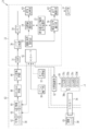
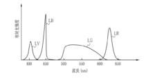
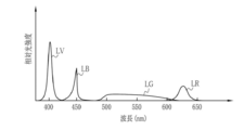
- FIG. 1 is an external view of an endoscope system according to a first embodiment. It is a block diagram which shows the function of an endoscope system. It is a figure which shows the light intensity spectrum of the illumination light of normal observation mode. It is a figure which shows the light intensity spectrum of the illumination light of special observation mode. It is a block diagram explaining an image processing part. It is a figure explaining an index value and a photography condition storage part. It is a figure explaining an index value selection part. It is a figure explaining an imaging condition extraction part. It is a figure which shows the display screen of a display part. It is a flowchart explaining the effect
- the endoscope system 10 includes an endoscope 12, a light source device 14, a processor device 16, a display unit 18, and an operation input unit 19.
- the endoscope 12 images an observation site in a living body as a subject.
- the light source device 14 supplies illumination light for illuminating the observation site to the endoscope 12.
- the processor device 16 generates a display image of the observation site using an imaging signal obtained by imaging.
- the display unit 18 is a monitor that displays a display image and information attached to the display image.
- the operation input unit 19 is a console such as a keyboard and a mouse, and functions as a user interface that receives input operations such as designation of a region of interest (ROI) and function setting.
- the display unit 18 and the operation input unit 19 are electrically connected to the processor device 16.
- the endoscope 12 is optically connected to the light source device 14 and electrically connected to the processor device 16.
- the endoscope 12 includes an insertion part 12a and an operation part 12b.
- the insertion part 12a is a part that is inserted into the digestive tract of a living body.
- the insertion part 12a has the front-end
- the distal end portion 21 has an illumination window, an observation window, an air / water feeding nozzle, and a forceps outlet (all not shown) on the distal end surface.
- the illumination window is for irradiating the observation site with illumination light.
- the observation window is for capturing light from the observation site.
- the air / water supply nozzle is for cleaning the illumination window and the observation window.
- the forceps outlet is for performing various treatments using a forceps and a treatment tool such as an electric knife.
- the bending portion 22 is configured by connecting a plurality of bending pieces, and is bent in the vertical and horizontal directions.
- the flexible tube portion 23 has flexibility and can be inserted into a tortuous duct such as an esophagus or
- the operation unit 12b includes an angle knob 25, an image storage operation unit 26, a mode switching unit 27, and a zoom operation unit 28.
- the angle knob 25 is used for an operation in which the bending portion 22 is bent and the distal end portion 21 is directed in a desired direction.
- the image storage operation unit 26 is used for an operation of storing a still image and / or a moving image in a storage (not shown).
- the mode switching unit 27 is used for an operation of switching the observation mode.
- the zoom operation unit 28 is used for an operation of changing the zoom magnification.
- the endoscope system 10 has a normal observation mode, a special observation mode, and an imaging condition guidance mode as observation modes.
- a normal observation mode an image (hereinafter referred to as a normal observation image) in which an observation target with a natural hue is shown is acquired.
- a special observation image an image that emphasizes at least the blood vessel to be observed (hereinafter referred to as a special observation image) is acquired.
- the imaging condition guidance mode will be described in detail later, an image (structure-enhanced image) in which the structure of the observation target is emphasized using the first index value that can be acquired under the first imaging condition acquired by the imaging condition acquisition unit 70 is acquired.
- a guidance display of the second shooting condition for acquiring a second index value that cannot be acquired under the first shooting condition is performed.
- the structure includes a blood vessel structure and a gland duct (pit pattern) structure.
- a structure when the structure of the blood vessel and the structure of the gland duct are not distinguished, they are referred to as a structure.
- the light source device 14 includes a light source 30 that emits illumination light and a light source control unit 32 that controls the light source 30.
- the light source 30 is, for example, a semiconductor light source such as a plurality of colors of LEDs (Light Emitting Diodes) having different wavelength ranges.
- the light source 30 is, for example, a V-LED (Violet Light Emitting Diode). 30a, B-LED (Blue Light Emitting Diode) 30b, G-LED (Green Light Emitting Diode) 30c, and R-LED (Red Light Emitting Diode) 30d.
- the emission wavelength of the V-LED 30a is 380 nm to 420 nm.
- the emission wavelength of the B-LED 30b is 420 nm to 500 nm.
- the emission wavelength of the G-LED 30c is 480 nm to 600 nm.
- the emission wavelength of the R-LED 30d is 600 nm to 650 nm.
- the light of each color may have the same center wavelength and peak wavelength, or may be different.
- the light source 30 includes an optical filter 30e that adjusts the wavelength band of the light emitted from the LED.
- the optical filter 30e is arranged on the optical path of the B-LED 30b and transmits a short wavelength component in the wavelength band of the B-LED 30b. Specifically, light of 450 nm or less in the wavelength band of the B-LED 30b is transmitted. Since the long wavelength component in the wavelength band of the B-LED 30b lowers the contrast between the mucous membrane and the blood vessel, the short wavelength component in the wavelength band of the B-LED 30b is described later by using the optical filter 30e.
- the guide 34 is supplied.
- the arrangement of the optical filter 30e is on the optical path of the B-LED 30b in this embodiment, but is not limited to this.
- the optical filter 30e may be arranged on the optical path of the G-LED 30c.
- the wavelength component transmitted by the optical filter 30e can be set as appropriate.
- the optical filter 30e transmits a part of the wavelength band of the G-LED 30c.
- the light source control unit 32 independently controls the lighting and extinguishing of the LEDs 30a to 30d, the balance of the emitted light amounts of the LEDs 30a to 30d (hereinafter referred to as the light amount ratio), etc. Adjust the light intensity and spectral spectrum.
- the light source control unit 32 controls the light amount ratio of each LED 30a to 30d for each observation mode by adjusting the current and voltage for driving each LED 30a to 30d.
- the light source control unit 32 turns on all the LEDs 30a to 30d to turn on the purple light LV emitted from the V-LED 30a and the blue light emitted from the B-LED 30b.
- Almost white illumination light (hereinafter referred to as white light) including LB, green light LG emitted from the G-LED 30c, and red light LR emitted from the R-LED 30d is generated.
- the blue light LB is light transmitted through the optical filter 30e, that is, light of 450 nm or less in the wavelength band of the B-LED 30b.
- the light source control unit 32 increases the amount of light emitted from the V-LED 30a as compared with the normal observation mode, and each of the B-LED 30b, the G-LED 30c, and the R-LED 30d. Illumination light having an emission light amount smaller than that in the normal observation mode is generated.
- the light source control unit 32 controls the light emission of each of the LEDs 30a to 30d according to the light amount ratio input by the operation input unit 19.
- the light quantity ratio input by the operation input unit 19 is 1: 0. : 0: 0, the light source controller 32 emits purple light LV by turning on only the V-LED 30a among the LEDs 30a to 30d.
- the violet light LV is light having an optimum wavelength band for observing the superficial blood vessels located shallow from the mucosal surface.
- the light source control unit 32 turns on only the B-LED 30b among the LEDs 30a to 30d, thereby turning on the blue light.
- LB emits light.
- the blue light LB is light having a wavelength band that is optimal for observing the middle layer blood vessel located deeper than the surface layer blood vessel. In the present embodiment, blue light LB is emitted in the shooting condition guidance mode.
- the illumination light emitted from the light source 30 enters the light guide 34 inserted into the insertion portion 12a.
- the light guide 34 is incorporated in the endoscope 12 and the universal cord, and propagates illumination light to the distal end portion 21 of the endoscope 12.
- the universal cord is a cord that connects the endoscope 12 to the light source device 14 and the processor device 16.
- a multimode fiber can be used as the light guide 34.
- the light guide 34 may be a thin fiber cable having a core diameter of 105 ⁇ m, a cladding diameter of 125 ⁇ m, and a diameter of 0.3 to 0.5 mm including the outer protective layer.
- the front end 21 has an illumination optical system 36 and an imaging optical system 38.
- the illumination optical system 36 has an illumination lens 40.
- the illumination light that has propagated through the light guide 34 illuminates the observation target via the illumination lens 40.
- the imaging optical system 38 includes an objective lens 42, a zoom lens 44, and an imaging sensor 46.
- Various kinds of light such as reflected light, scattered light, and fluorescence from the observation target enter the image sensor 46 through the objective lens 42 and the zoom lens 44.
- an image to be observed is formed on the image sensor 46.
- the zoom lens 44 freely moves between the tele end and the wide end by operating the zoom operation unit 28, and enlarges or reduces the observation target imaged on the image sensor 46.
- the imaging sensor 46 is a color imaging sensor in which any one of R (red), G (green), and B (blue) primary color filters is provided for each pixel. Output a signal.
- a CCD (Charge-Coupled Device) image sensor, a CMOS (Complementary Metal-Oxide Semiconductor) image sensor, or the like can be used.
- a complementary color image sensor provided with C (cyan), M (magenta), Y (yellow), and G (green) complementary color filters may be used.
- CMYG four-color image signals are output.
- CMYG four-color image signals into the RGB three-color image signals by complementary color-primary color conversion, it is possible to obtain RGB image signals similar to those of the image sensor 46.
- a monochrome sensor without a color filter may be used.
- a CDS (Correlated Double Sampling) / AGC (Automatic Gain Control) circuit 448 performs correlated double sampling and automatic gain control on the analog image signal output from the image sensor 46.
- An A / D (Analog-to-Digital) conversion circuit 50 converts an analog image signal that has passed through the CDS / AGC circuit 48 into a digital image signal.
- the A / D conversion circuit 50 inputs the digital image signal after A / D conversion to the processor device 16.
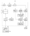
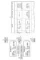
- the processor device 16 includes a controller 52, a DSP (Digital Signal Processor) 54, a noise reduction unit 56, a memory 58, an image processing unit 60, and a display control unit 62.
- DSP Digital Signal Processor
- the controller 52 includes a CPU (Central processing unit), a ROM (Read only memory) that stores a control program and setting data necessary for control, a RAM (Random access memory) as a working memory for loading the control program, and the like.
- the controller 52 controls the light source control unit 32 and the image sensor 46 in addition to controlling each unit of the processor device 16 by the CPU executing a control program.
- each part of the processor device 16 is a specific processor such as a programmable logic device (Programmable Logic Device: PLD) or an ASIC (Application Specific Integrated Circuit) that can change the circuit configuration after manufacturing a FPGA (Field Programmable Gate Array). You may comprise by the electrical circuit etc. which have a circuit structure designed exclusively for performing a process. The same applies to the inside of the endoscope 12 and the light source device 14.
- the DSP 54 acquires a digital image signal from the endoscope 12, and performs various processes such as defect correction processing, offset processing, gain correction processing, linear matrix processing, gamma conversion processing, and demosaicing processing on the acquired image signal. Apply signal processing.
- defect correction process the signal of the defective pixel of the image sensor 46 is corrected.
- offset process the dark current component is removed from the image signal subjected to the defect correction process, and an accurate zero level is set.
- the gain correction process adjusts the signal level by multiplying the image signal subjected to the offset process by a specific gain.
- Linear matrix processing enhances the color reproducibility of gain-corrected image signals.
- the gamma conversion process adjusts the brightness and saturation of the image signal subjected to the linear matrix process.
- demosaic processing also referred to as isotropic processing or synchronization processing
- a signal of a color that is insufficient at each pixel is generated by interpolation.
- all the pixels have RGB signals.
- the noise reduction unit 56 performs noise reduction processing by, for example, a moving average method or a median filter method on the image signal subjected to demosaic processing or the like by the DSP 54 to reduce noise.
- the image signal with reduced noise is stored in the memory 58.
- the image processing unit 60 acquires an image signal from the memory 58, performs predetermined image processing on the acquired image signal, and generates a display image showing an observation target.
- the content of the image processing performed by the image processing unit 60 differs depending on the observation mode.
- the image processing unit 60 performs image processing such as color conversion processing, color enhancement processing, and structure enhancement processing to generate a normal observation image.
- the color conversion process is a process of performing color conversion on an image signal by 3 ⁇ 3 matrix processing, gradation conversion processing, three-dimensional LUT (lookup table) processing, and the like.
- the color enhancement process is performed on the image signal subjected to the color conversion process.
- the structure enhancement process is a process for enhancing a specific tissue or structure included in an observation target such as a blood vessel or a gland duct, and is performed on the image signal after the color enhancement process.
- the image processing unit 60 generates a special observation image by performing the above-described various image processes that emphasize blood vessels. In the special observation mode, since the amount of light emitted from the V-LED 30a is large, the superficial blood vessels are emphasized in the special observation image.
- the image processing unit 60 includes a base image generation unit 100, a structure extraction unit 102, an index value calculation unit 108, and an enhanced image generation unit 110.
- various image processing is performed by the above-described units.
- the base image generation unit 100 generates a base image in which the structure of the observation target is represented by different colors for the image signal acquired from the memory 58, and acquires this as an endoscopic image. That is, the base image generation unit 100 acquires an endoscopic image obtained by imaging an observation target with an endoscope.
- the base image is represented by a color according to the set light amount ratio, and the color is slightly different from the normal observation image.
- the base image an image obtained by photographing at a set light amount ratio and having a color balance such that the white plate becomes white, one of the R channel, the G channel, and the B channel of the display unit 18 Change the tone balance of the gray image and the image signal obtained by assigning the image signal to (for example, assigning the image signal to the G channel when the light amount of the green light LG is large in the illumination light amount ratio).
- the base image generation unit 100 corresponds to the image acquisition unit of the present invention.
- the structure extraction unit 102 uses the base image to generate a structure extraction image obtained by extracting the structure to be observed. For example, when the observation target is illuminated with illumination light of different wavelength bands by the light source device 14, the structure extraction unit 102 takes a difference between the images obtained by photographing the observation target under illumination with each illumination light. To extract blood vessels. Specifically, by taking a difference between an image obtained by photographing the observation target illuminated with purple light LV and an image obtained by photographing the observation target illuminated with blue light LB, Alternatively, blood vessels that are shallower than the surface blood vessels can be extracted. In addition to or instead of extracting blood vessels as described above, the structure of the gland duct may be extracted. Note that the structure extraction method is not limited to the above method.
- the structure extraction unit 102 extracts blood vessels and gland ducts from the entire base image. However, when a region of interest is specified by an operation of the operation input unit 19, only within the specified region of interest. Blood vessels and gland ducts may be extracted.
- the index value calculation unit 108 calculates an index value related to the structure to be observed using the structure extraction image.
- the types of index values are, for example, blood vessel density, blood vessel thickness uniformity, blood vessel complexity, surface structure uniformity, and the like. Note that the types of index values are not limited to the above examples.
- the density of blood vessels is the proportion of blood vessels in a unit area.
- the uniformity of the thickness of the blood vessel is an index value related to the variation in the thickness of the blood vessel.
- the complexity of a blood vessel is an index value indicating how complex the shape of the blood vessel is. For example, the number of branch points (the number of branches) of the extracted blood vessel, the degree of meandering of the blood vessel, and the degree of bending of the extracted blood vessel.
- the uniformity of the surface structure is an index value relating to the variation in the shape of the gland duct.
- the index value calculation unit 108 calculates an index value selected by an index value selection unit 74 described later from among the plurality of index values.
- the index value calculation unit 108 calculates an index value for each pixel of the structure extraction image. For example, the index value of one pixel is calculated using data of pixels in a predetermined range (for example, a range of 99 ⁇ 99 pixels centered on the pixel whose index value is calculated) including the pixel whose index value is calculated.
- a predetermined range for example, a range of 99 ⁇ 99 pixels centered on the pixel whose index value is calculated
- the index value calculation unit 108 calculates the index value within the set region of interest.
- the index value calculation unit 108 calculates the index value for the entire structure extraction image.
- the index value calculation unit 108 calculates the index value using the structure extraction image in this embodiment, but calculates the index value using the endoscopic image acquired by the base image generation unit 100 as the image acquisition unit. You may do it. For example, when the structure of the observation target appears clearly in the endoscopic image, the index value is calculated using the endoscopic image.
- the emphasized image generation unit 110 generates a structure emphasized image as the first structure emphasized image using the generated base image and the calculated index value.
- the emphasized image generation unit 110 generates a structure-enhanced image by, for example, overlapping processing information based on the index value with respect to the base image.
- As the overlap process there is a coloring process according to the index value.
- a region having an index value equal to or greater than a certain value is displayed in a pseudo color with respect to the base image, and the structure to be observed is emphasized.
- Information indicating the index value itself may be overlapped with the base image.
- the enhanced image generation unit 110 inputs the generated structure enhanced image to the display control unit 62.
- the enhanced image generation unit 110 corresponds to the first enhanced image generation unit of the present invention.
- the display control unit 62 controls the display unit 18 to display the display image generated by the image processing unit 60. Thereby, the normal observation image is displayed in the normal observation mode, and the special observation image is displayed in the special observation mode. In the shooting condition guidance mode, a structure-enhanced image is displayed and guidance is displayed.
- the processor device 16 further includes an imaging condition acquisition unit 70, an index value and imaging condition storage unit 72, an index value selection unit 74, and an imaging condition extraction unit 76 (see FIG. 2).
- the index value and photographing condition storage unit 72 is configured by a recording medium such as an HDD (Hard disk drive) or an SSD (Solid disk drive).
- the imaging condition acquisition unit 70 acquires the first imaging condition as an imaging condition for imaging the observation target with the endoscope 12.
- the first imaging condition includes at least one of a light amount ratio of each of the LEDs 30a to 30d, an observation distance to the observation target, and a zoom magnification of the endoscope 12.
- the light quantity ratio is acquired from the light source control unit 32.
- the observation distance includes, for example, a non-magnification observation distance in which the observation distance is a long distance, a magnification observation distance in which the observation distance is a short distance, and the like, and is acquired by an exposure amount obtained from an image.
- the observation distance may be acquired by image frequency analysis.
- the zoom magnification includes, for example, non-magnification for non-magnification observation and low magnification to high magnification that enables magnification observation, and is acquired based on a change operation of the zoom operation unit 28.
- the imaging condition acquisition unit 70 acquires the light amount ratio, the observation distance, and the zoom magnification as the first imaging condition.
- the imaging condition acquisition unit 70 inputs the acquired first imaging condition to the index value selection unit 74 and the imaging condition extraction unit 76.
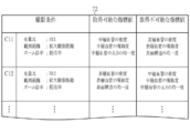
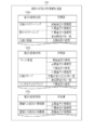
- the index value and shooting condition storage unit 72 stores a plurality of shooting conditions, an index value that can be acquired under each shooting condition, and an index value that cannot be acquired in association with each other.
- An index value that cannot be acquired under certain imaging conditions is not only an index value that cannot be acquired in principle, but it can be acquired in principle, but it can be acquired from the image for a certain purpose. Includes index values that cannot be calculated with.
- the index value and shooting condition storage unit 72 stores a light amount ratio, an observation distance, and a zoom magnification as shooting conditions.
- the shooting conditions stored in the index value and shooting condition storage unit 72 include at least the first shooting condition acquired by the shooting condition acquisition unit 70.
- the index value and shooting condition storage unit 72 includes a first index value that can be acquired under the first shooting condition and a second index value that cannot be acquired under the first shooting condition but can be acquired under the second shooting condition.
- a correspondence relationship between a plurality of index values and shooting conditions is stored.
- the shooting conditions stored in the index value and shooting condition storage unit 72 are the light amount ratio, the observation distance, and the zoom magnification in the present embodiment, but are not limited thereto.
- the imaging conditions may include the observation mode (normal observation mode and special observation mode, etc.), the light emission amount of the light source 30, the brightness of the entire or part of the display screen (region of interest, etc.).
- the light amount ratio as the imaging condition may include a light amount ratio in the normal observation mode and a light amount ratio in the special observation mode.
- the index value and shooting condition storage unit 72 associates different index values with, for example, the shooting condition C11 and the shooting condition C12 among the plurality of shooting conditions.
- the photographing condition C11 the light amount ratio is R11
- the observation distance is an enlarged observation distance
- the zoom magnification is a low magnification.
- the index values that can be acquired under this imaging condition C11 are the density of the middle layer blood vessel, the complexity of the middle layer blood vessel, and the uniformity of the thickness of the middle layer blood vessel.
- the index values that cannot be acquired under the imaging condition C11 are the density of the surface blood vessels, the complexity of the surface blood vessels, and the uniformity of the surface structure.
- the light amount ratio R11 is, for example, 0: 1: 0: 0. For this reason, the blue light LB is emitted as illumination light at the light quantity ratio R11.
- the photographing condition C12 is that the light quantity ratio is R12, the observation distance is an enlarged observation distance, and the zoom magnification is a low magnification.
- the index values that can be acquired under this imaging condition C12 are the density of the superficial blood vessels, the complexity of the superficial blood vessels, and the uniformity of the surface structure.
- the index values that cannot be acquired under the imaging condition C12 are the density of the middle layer blood vessel, the complexity of the middle layer blood vessel, and the uniformity of the thickness of the middle layer blood vessel.
- the light amount ratio R12 is, for example, 1: 0: 0: 0. For this reason, purple light LV is emitted as illumination light at the light quantity ratio R12.
- the index value selection unit 74 selects the first index value by referring to the index value and imaging condition storage unit 72 using the first imaging condition acquired by the imaging condition acquisition unit 70.
- the index value selection unit 74 displays the index value and A shooting condition C11 that matches the first shooting condition is extracted from the plurality of shooting conditions stored in the shooting condition storage unit 72.
- the index value selection unit 74 selects the density of the middle layer blood vessel, the complexity of the middle layer blood vessel, and the uniformity of the thickness of the middle layer blood vessel as the first index value that can be acquired under the extracted imaging condition C11. Then, the index value selection unit 74 inputs the selected first index value to the index value calculation unit 108 of the image processing unit 60.
- the imaging condition extraction unit 76 refers to the index value and imaging condition storage unit 72 using the first imaging condition acquired by the imaging condition acquisition unit 70, and can acquire a second index value. To extract.
- the shooting condition extraction unit 76 first extracts a shooting condition C11 that matches the first shooting condition from a plurality of shooting conditions stored in the index value and shooting condition storage unit 72. .
- the imaging condition extraction unit 76 selects the density of the superficial blood vessels, the complexity of the superficial blood vessels, and the uniformity of the surface structure as the second index values that cannot be acquired under the extracted imaging conditions C11.
- the imaging condition extraction unit 76 sets the imaging condition C12 (light quantity ratio; R12, observation distance; magnified observation distance, zoom magnification; low magnification) that can acquire the second index value selected from the plurality of imaging conditions to the second. Extracted as shooting conditions. Then, the shooting condition extraction unit 76 inputs the extracted second shooting condition to the display control unit 62.
- the display control unit 62 controls the display unit 18 to display a guidance that the second index value can be acquired based on the second shooting condition extracted by the shooting condition extraction unit 76. Therefore, the display unit 18 corresponds to the guidance display unit of the present invention.
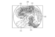
- the display control unit 62 controls the display unit 18 to display the structure-enhanced image 112, information 114 indicating the second index value that cannot be acquired under the current first imaging condition, Information 116 indicating the second imaging condition for acquiring the two index values is displayed.
- the structure-enhanced image 112 is displayed in the left area of the display unit 18.
- Information 114 indicating the second index value that cannot be acquired under the first imaging condition is displayed in the upper right area of the display unit 18.
- Information 116 indicating the second imaging condition for acquiring the second index value is displayed in the lower right area of the display unit 18.
- a region 118 in which the complexity of the middle-layer blood vessel is a certain value or more is displayed in a pseudo color.
- This region 118 is, for example, a red color.
- the structure-enhanced image 112 is an image using the blue light LB as illumination light
- the middle layer blood vessel is clearly shown
- the surface layer blood vessel 119 is unclear compared to the middle layer blood vessel. Therefore, although the index value related to the middle-layer blood vessel can be accurately acquired from the structure-enhanced image 112 obtained under the first imaging condition, it is difficult to accurately acquire the index value related to the surface blood vessel 119.
- the shape of the gland duct is not clearly shown, it is difficult to obtain the uniformity of the surface structure.
- “the density of the superficial blood vessels, the complexity of the superficial blood vessels, and the uniformity of the surface structure” is displayed as information 114 indicating the second index value that cannot be acquired under the first imaging condition. Further, “light quantity ratio; R12, observation distance; enlarged observation distance, zoom magnification; low magnification” is displayed as information 116 indicating the second imaging condition for acquiring these second index values.
- illumination light is emitted according to the light amount ratio input by the operation input unit 19.
- the blue light LB is emitted by turning on only the B-LED 30b among the LEDs 30a to 30d.
- the imaging sensor 46 images the observation target under illumination with the illumination light.
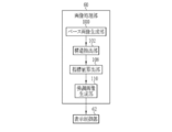
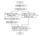
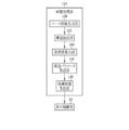
- the base image generation unit 100 generates a base image from the image signal output by the imaging sensor 46, and acquires this as an endoscopic image (S11).
- the structure extraction unit 102 generates a structure extraction image obtained by extracting the structure to be observed from the base image.
- the imaging condition acquisition unit 70 acquires a first imaging condition as an imaging condition for performing the above imaging (S12).
- the first imaging conditions acquired by the imaging condition acquisition unit 70 are the light quantity ratio of each of the LEDs 30a to 30d, the observation distance to the observation target, and the zoom magnification of the endoscope 12.
- the imaging condition acquisition unit 70 inputs the acquired first imaging condition to the index value selection unit 74 and the imaging condition extraction unit 76.
- the index value selection unit 74 refers to the index value and imaging condition storage unit 72, and selects a first index value that can be acquired under the first imaging condition acquired by the imaging condition acquisition unit 70 (S13).
- the index value and shooting condition storage unit 72 includes a plurality of first index values that can be acquired under the first shooting conditions and second index values that cannot be acquired under the first shooting conditions and can be acquired under the second shooting conditions. The correspondence relationship between the index value and the shooting condition is stored. From this index value and imaging condition storage unit 72, the index value selection unit 74 extracts imaging conditions that match the acquired first imaging conditions. Then, the index value selection unit 74 selects the first index value associated with the extracted shooting condition. The index value selection unit 74 inputs the selected first index value to the index value calculation unit 108.
- the index value calculation unit 108 calculates the first index value selected by the index value selection unit 74 using the structure extraction image (S14).
- the emphasized image generation unit 110 generates a structure emphasized image using the calculated first index value and the base image (S15).
- the enhanced image generation unit 110 inputs the generated structure enhanced image to the display control unit 62.
- the imaging condition extraction unit 76 refers to the index value and imaging condition storage unit 72, and extracts a second imaging condition for acquiring a second index value that cannot be acquired under the first imaging condition (S16). Specifically, the shooting condition extraction unit 76 extracts shooting conditions that match the first shooting condition from the index value and shooting condition storage unit 72. The shooting condition extraction unit 76 selects a second index value associated with the extracted shooting condition. Then, the shooting condition extraction unit 76 extracts a shooting condition capable of acquiring the selected second index value from the plurality of shooting conditions as the second shooting condition. The shooting condition extraction unit 76 inputs the extracted second shooting condition to the display control unit 62.
- the display control unit 62 controls the display unit 18 to display the structure-enhanced image generated by the enhanced image generation unit 110 and to acquire the second index value under the second imaging condition extracted by the imaging condition extraction unit 76.
- a guidance message is displayed (S17).
- an index value that cannot be acquired under the current shooting conditions can be acquired.
- the display control unit 62 displays a guidance indicating that the second index value can be acquired under the second shooting condition extracted by the shooting condition extraction unit 76.
- the display control unit 62 displays the shooting condition.
- a guidance display may be displayed that the first index value can be acquired under the first imaging condition acquired by the acquisition unit 70.
- the display control unit 62 controls the display unit 18 to acquire information 114 indicating the second index value that cannot be acquired under the current first imaging condition, and the second index value.
- information 116 indicating the second imaging condition for example, information 120 indicating the current first imaging condition and information 121 indicating the first index value obtainable under the current first imaging condition are further displayed.
- a guidance display indicating that the second index value cannot be obtained under the current first shooting condition is performed.
- a guidance display of specific settings for changing the current first shooting condition to the second shooting condition is performed.
- the shooting condition extraction unit 76 extracts the second shooting condition that can acquire an index value that cannot be acquired under the first shooting condition. In the second embodiment, the shooting condition extraction unit 76 extracts the first shooting condition. An imaging condition that cannot be acquired under imaging conditions and that can acquire a second index value suitable for diagnostic purposes is extracted.
- a processor device 130 is used instead of the processor device 16 of the first embodiment.
- the processor device 130 includes a diagnostic purpose acquisition unit 132, a data transmission / reception unit 134, and a diagnostic purpose and index value storage unit 136.
- the processor device 130 includes a shooting condition extraction unit 138 instead of the shooting condition extraction unit 76.
- the diagnostic purpose acquisition unit 132 acquires the diagnostic purpose from the endoscope information management system 139 connected via a data transmission / reception unit 134 so as to communicate with each other via a network such as a LAN (Local Area Network).
- the endoscope information management system 139 is a file server of a system for filing endoscopic images such as PACS (Picture Archiving and Communication) System.
- the endoscope information management system 139 includes a data storage unit 139a, and stores examination information including a diagnosis purpose and patient information input from an input terminal (not shown) as endoscope information management data. To do.
- the diagnostic purpose acquisition unit 132 receives the endoscope information management data from the data storage unit 139a, and acquires the diagnostic purpose by extracting it from the endoscope information management data.
- the diagnostic purpose acquisition unit 132 inputs the acquired diagnostic purpose to the imaging condition extraction unit 76.
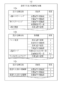
- the diagnostic purpose and index value storage unit 136 stores a plurality of index values for each diagnostic purpose.
- the diagnostic purpose includes a first diagnostic purpose including screening and scrutiny, a second diagnostic purpose related to the type of disease, and a third diagnostic purpose related to the stage of the disease.
- the first diagnostic purpose is not limited to the above screening and scrutiny, but includes a wide variety, for example, treatment, follow-up observation, and the like.
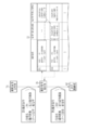
- the diagnostic purpose and index value storage unit 136 has first to third index value selection tables 136a to 136c.
- the first index value selection table 136a stores a first diagnostic purpose and an index value used for the first diagnostic purpose in association with each other.
- the complexity of the surface blood vessels and the complexity of the middle blood vessels are associated with the screening of the large intestine, and the complexity of the middle blood vessels and the surface are compared with the screening of the stomach.
- the uniformity of the structure is associated, and the density of the superficial blood vessels is associated with the detailed examination of the large intestine.
- the second index value selection table 136b stores the second diagnostic purpose and the index value used for the second diagnostic purpose in association with each other.
- the density of the surface blood vessels, the complexity of the surface blood vessels, the density of the middle blood vessels, and the complexity of the middle blood vessels are associated with Barrett's esophagus.
- the uniformity of the thickness of the middle-layer blood vessel is associated with the uniformity of the surface structure, and the density of the middle-layer blood vessel is associated with angiodispersia.
- the third index value selection table 136c stores a third diagnostic purpose and an index value used for the third diagnostic purpose in association with each other.
- the complexity of the superficial blood vessels and the complexity of the middle blood vessels are associated with the remission period of ulcerative colitis, and the active period of ulcerative colitis is The complexity of the superficial blood vessels is associated.
- first to third index value selection tables 136a to 136c can be appropriately updated by an input operation of the operation input unit 19, for example.
- first to third index value selection tables 136a to 136c can newly add correspondences.
- the imaging condition extraction unit 138 extracts the second imaging condition using the second index value that cannot be acquired under the first imaging condition and is used for the acquired diagnostic purpose. Specifically, the imaging condition extraction unit 138 extracts the second imaging condition according to at least one of the first to third diagnostic purposes. More specifically, the imaging condition extraction unit 138 refers to the first index value selection table 136a of the index value storage unit 104 when acquiring the first diagnosis purpose, and acquires the second diagnosis purpose. In this case, the second index value selection table 136b is referred to, and when the third diagnosis purpose is acquired, the third index value selection table 136c is referred to.
- the imaging condition extraction unit 138 refers to the diagnostic purpose and index value storage unit 136 and selects an index value used for the diagnostic purpose acquired by the diagnostic purpose acquisition unit 132. For example, when the acquired second diagnostic purpose is a colon polyp, the imaging condition extraction unit 138 reads from the second index value selection table 136b the thickness uniformity of the middle-layer blood vessels and the surface structure uniformity. And select.
- the imaging condition extraction unit 138 extracts the imaging condition C21 that matches the first imaging condition, as in the first embodiment.
- the light quantity ratio R21 is 1: 0: 0: 0.
- purple light LV is emitted as illumination light at the light quantity ratio R21.
- the imaging condition extraction unit 138 selects an index value used for diagnostic purposes as the second index value when an index value used for diagnostic purposes is included in the extracted index values that cannot be acquired under the imaging condition C21. . Note that if the index value that is not acquired under the extracted imaging condition C21 does not include an index value that is used for diagnostic purposes, the imaging condition extraction unit 138 performs the same processing as in the first embodiment.
- the thickness uniformity of the middle-layer blood vessel used in the diagnosis of colorectal polyps is an index value that cannot be acquired under the imaging condition C21, and the uniformity of the surface structure can be acquired under the imaging condition C21. ing. Therefore, the imaging condition extraction unit 138 selects the thickness uniformity of the middle-layer blood vessel as the second index value. Then, the imaging condition extraction unit 138 extracts, as a second imaging condition, an imaging condition C31 that can acquire the thickness uniformity of the selected middle blood vessel from among a plurality of imaging conditions.
- the light quantity ratio R31 is set to 0: 1: 0: 0. For this reason, the blue light LB is emitted as illumination light at the light quantity ratio R31.
- the shooting condition extraction unit 138 inputs the extracted second shooting condition to the display control unit 62.
- the display control of the display control unit 62 is the same as that in the first embodiment. As described above, by displaying the guidance that the index value used for the purpose of diagnosis cannot be acquired under the current imaging conditions, the index value suitable for the purpose of diagnosis is more reliably acquired.
- the diagnostic purpose acquisition unit 132 acquires the diagnostic purpose from the endoscope information management system 139 via the network.
- the endoscope information management system In addition to acquiring the diagnostic purpose from 139, the diagnostic purpose input by the operation input unit 19 as the diagnostic purpose input unit may be acquired.
- the imaging condition extraction unit 138 preferentially uses the diagnostic purpose input by the operation input unit 19. This makes it possible to continue the examination while switching to a diagnostic purpose different from the diagnostic purpose acquired from the endoscope information management system 139 during the diagnosis.
- the diagnostic purpose acquisition unit 132 may acquire the diagnostic purpose input by the operation input unit 19 instead of acquiring the diagnostic purpose from the endoscope information management system 139. In this case, the diagnostic purpose can be acquired even when the endoscope information management system 139 is not connected via the network.
- the diagnostic purpose is used when extracting the second imaging condition.
- the diagnostic purpose is used when selecting the first index value.
- the diagnostic purpose acquisition unit 132 inputs the acquired diagnostic purpose to the index value selection unit 74.
- the index value selection unit 74 refers to the diagnostic purpose and index value storage unit 136 and selects an index value that can be acquired under the first imaging condition and is used for the acquired diagnostic purpose as the first index value. .
- the index value selection unit 74 inputs the selected first index value to the index value calculation unit 108. Subsequent processing is the same as that in the first embodiment, and thus description thereof is omitted.
- the structure-enhanced image generated by the emphasized-image generating unit 110 is highlighted with a first index value used for diagnostic purposes.
- the display control unit 62 may display a guidance indicating that the first index value used for diagnosis purposes can be acquired under the current first imaging condition.
- the fourth embodiment includes a diagnostic purpose and index value storage unit 142 instead of the diagnostic purpose and index value storage unit 136.
- the diagnostic purpose and index value storage unit 142 stores a weighting coefficient used in a structure parameter calculation unit 146, which will be described later, in association with the diagnostic purpose and the index value.
- the diagnostic purpose and index value storage unit 142 includes first to third index value selection tables 142a to 142c. Regarding the first to third index value selection tables 142a to 142c, the relationship between the diagnostic purpose and the index value is the same as that of the diagnostic purpose and index value storage unit 136, so that the description thereof will be omitted. Will be described.
- the first index value selection table 142a stores the first diagnostic purpose, the index value used for the first diagnostic purpose, and the coefficient for each index value in association with each other.
- the coefficient for the complexity of the superficial blood vessels is 0.5
- the coefficient for the complexity of the middle blood vessels is 1.
- the coefficient for the uniformity of the surface structure is 1.
- the coefficient for the density of the superficial blood vessels is 1.
- the second index value selection table 142b stores the second diagnostic purpose, the index value used for the second diagnostic purpose, and the coefficient for each index value in association with each other.
- the coefficients for the density of the superficial blood vessels, the complexity of the superficial blood vessels, the density of the middle blood vessels and the complexity of the middle blood vessels are set to 1, respectively.
- the coefficient for the uniformity of the thickness of the middle-layer blood vessel is 1, and the coefficient for the uniformity of the surface structure is 0.5.
- the coefficient for the density of the middle blood vessel is 1.
- the third index value selection table 142c stores the third diagnostic purpose, the index value used for the third diagnostic purpose, and the coefficient for each index value in association with each other. For example, in the remission period of ulcerative colitis, the coefficient for the complexity of the superficial blood vessel and the complexity of the middle blood vessel is 1 respectively. For the active phase of ulcerative colitis, the coefficient for the complexity of the superficial blood vessels is 1.
- the correspondence relationships stored in the first to third index value selection tables 142a to 142c can be updated as appropriate by an input operation of the operation input unit 19, for example.
- the first to third index value selection tables 142a to 142c can newly add correspondences.
- any one of the first to third diagnostic purposes is acquired by the diagnostic purpose acquisition unit 132, but a composite of a plurality of diagnostic purposes such as the first diagnostic purpose and the second diagnostic purpose.
- a table for multiple purposes may be provided in the diagnostic purpose and index value storage unit 142.
- the composite purpose table stores a composite purpose, an index value used for the composite purpose, and a coefficient for each index value in association with each other.
- the index value used for the composite purpose is an index value used for each diagnostic purpose constituting the composite purpose.
- the coefficient stored in the composite purpose table is set to a larger value, for example, among the index values used for each diagnostic purpose constituting the composite purpose, the index value having a large number of overlapping.
- the index value selection unit 74 refers to the diagnostic purpose and index value storage unit 142, and selects an index value that can be acquired under the first imaging condition and is used for the acquired diagnostic purpose as the first index value. .
- the index value selection unit 74 inputs the selected first index value to the index value calculation unit 108.
- the index value calculation unit 108 calculates the first index value selected by the index value selection unit 74, as in the first embodiment.
- an image processing unit 144 shown in FIG. 18 is provided instead of the image processing unit 60 of the third embodiment.
- the image processing unit 144 includes a structure parameter calculation unit 146 in addition to the components of the image processing unit 60 of the third embodiment, and includes an enhanced image generation unit 148 instead of the enhanced image generation unit 110.
- the structural parameter calculation unit 146 calculates a structural parameter using the first index value calculated by the index value calculation unit 108. Specifically, the structural parameter calculation unit 146 calculates a structural parameter by performing a calculation by weighting the plurality of first index values with a coefficient (weighting coefficient) determined according to the diagnostic purpose.
- the structural parameter calculation unit 146 refers to the diagnostic purpose and index value storage unit 142 when calculating the structural parameter, and uses a coefficient associated with the first index value calculated by the index value calculation unit 108.
- the structural parameter is a numerical value calculated using the index value, imitating the viewpoint of a doctor who makes a diagnosis considering the index value comprehensively.
- the structural parameter is calculated by an operation such as addition of index values having different dimensions (units), for example.
- the structural parameter has no physical meaning, but functions as a diagnostic index. That is, the difference between the structure parameter and the index value is that the physical parameter has no physical meaning.
- the structural parameter calculation unit 146 calculates the density of the superficial blood vessels, the complexity of the superficial blood vessels, the density of the middle blood vessels, and the density of the middle blood vessels.
- the structural parameters are calculated by multiplying each of the complexity by 1 and adding.
- the structural parameter calculation unit 146 calculates one structural parameter using a plurality of index values, but is not limited thereto, and may calculate two or more structural parameters.
- the calculation method of a structure parameter is arbitrary.
- the structural parameter may be calculated by performing an operation in which addition, subtraction, multiplication, and division are mixed. May be calculated.
- the structural parameter calculation unit 146 may calculate the structural parameter by multiplying one index value by a weighting coefficient.
- the emphasized image generation unit 148 generates a structure-enhanced image as a second structure-enhanced image using the generated base image and the calculated structure parameter. For example, the emphasized image generation unit 148 generates a structure emphasized image by performing overlap processing on information based on the structure parameter with respect to the base image.
- the enhanced image generation unit 148 corresponds to the second enhanced image generation unit of the present invention.
- the areas 151 to 153 are displayed in different colors according to the structure parameters.
- the region 151 has the smallest structural parameter and has a blue color.
- the region 152 has a larger structural parameter than the region 151 and has a yellowish color.
- the region 153 has a larger structural parameter than the region 152 and has a red color. Note that information indicating the structure parameter value itself may overlap the base image. Thereby, a structure suitable for a diagnostic purpose can be emphasized more.
- the structural parameter may be calculated using only the first index value by multiplying the first index value that can be acquired under the current shooting conditions by a specific coefficient.
- the specific coefficient is determined in advance by machine learning, for example, and is stored in the diagnostic purpose and index value storage unit 142.
- the second shooting condition when the second shooting condition is displayed as guidance on the display unit 18, it is displayed as character information.
- the second index value is displayed under the second shooting condition. It is good also as an icon display which can identify that it can acquire.
- the light amount ratio is displayed as the second imaging condition
- the color of the light source is displayed with a color bar or the like.
- the zoom magnification is displayed as the second photographing condition
- a magnifying glass or the like is displayed.
- an animation or the like that brings the endoscope closer to or away from the observation target is displayed.
- a voice guide from a speaker may notify that the second index value can be acquired under the second imaging condition.
Abstract
An endoscopic system which can provide guidance enabling acquisition of an index value that cannot be acquired under current imaging conditions, and an operation method of said endoscopic system are provided. This endoscopic system is provided with an imaging condition acquisition unit, an index value and imaging condition storage unit, an imaging condition extraction unit, and a guidance display unit. The imaging condition acquisition unit acquires a first imaging condition as the imaging condition under which the observation target is observed with an endoscope. The index value and imaging condition storage unit stores correspondence relations between imaging conditions and index values which, as index values relating to the structure of the observation target, include a first index value that can be acquired under a first imaging condition, and a second index value that cannot be acquired under the first imaging condition but that can be acquired under a second imaging condition. The imaging condition extraction unit refers to the index value and imaging condition storage unit and extracts a second imaging condition. The guidance display unit displays guidance indicating that the second index value can be acquired under the extracted second imaging condition.
Description
本発明は、内視鏡システム及びその作動方法に関する。
The present invention relates to an endoscope system and an operation method thereof.
医療分野においては、光源装置、内視鏡、及びプロセッサ装置を備える内視鏡システムを用いた診断が広く行われている。内視鏡システムは、光源装置が発する照明光を、内視鏡を介して観察対象に照射し、その照明光で照明中の観察対象を撮像して得た画像信号に基づいて、プロセッサ装置が観察対象の画像を生成する。この画像をモニタに表示することにより、医師は、モニタ上の画像を見ながら診断を行うことができる。
In the medical field, diagnosis using an endoscope system including a light source device, an endoscope, and a processor device is widely performed. The endoscope system irradiates illumination light emitted from a light source device to an observation target via the endoscope, and a processor device based on an image signal obtained by imaging the observation target under illumination with the illumination light. An image to be observed is generated. By displaying this image on the monitor, the doctor can make a diagnosis while viewing the image on the monitor.
また、近年の内視鏡診断においては、診断目的などその他の各種条件に合わせて、光源の光源バランスなど撮影条件を変更することが行われつつあり(特許文献1~4)、また、各種条件に適したガイダンス表示をすることも行われつつある(特許文献5)。例えば、特許文献1、2に示すように、観察部位や観察倍率に応じて、光源波長のバランスを切り替えて、可視化することも行われつつある。これら特許文献1、2では、拡大観察時には表層血管を観察し、非拡大観察時には白色光の色味で全体的な観察を行うために、拡大観察時には短波の光で照明し、非拡大観察時には白色光で照明している。
Further, in recent endoscopic diagnosis, imaging conditions such as the light source balance of light sources are being changed in accordance with various other conditions such as diagnostic purposes (Patent Documents 1 to 4). Guidance display suitable for use is being performed (Patent Document 5). For example, as shown in Patent Documents 1 and 2, visualization is being performed by switching the balance of light source wavelengths in accordance with the observation site and the observation magnification. In these Patent Documents 1 and 2, in order to observe the superficial blood vessels at the time of magnified observation, and to observe the entire color with the color of white light at the time of non-magnified observation, illumination with short wave light at the time of magnified observation, and at the time of non-magnified observation Illuminated with white light.
また、特許文献3では、酸素飽和度などの吸光成分濃度の算出精度を高めるために、プレ撮影にて血管領域とその他の領域の吸光成分濃度の差分を元に、光源の波長セットを切り替えている。また、特許文献4では、内視鏡の観察部位や機種名に応じて、撮影光源の光源バランスを調整している。また、特許文献5では、観察条件に適した光源バランスのモードを、モニタ上にガイダンス表示することを行っている。
Further, in Patent Document 3, in order to improve the calculation accuracy of the absorption component concentration such as oxygen saturation, the wavelength set of the light source is switched based on the difference between the absorption component concentrations of the blood vessel region and other regions in the pre-photographing. Yes. In Patent Document 4, the light source balance of the imaging light source is adjusted in accordance with the observation site of the endoscope and the model name. In Patent Document 5, a light source balance mode suitable for observation conditions is displayed on a monitor as a guidance.
更に、近年の内視鏡診断においては、特許文献6に示すように、医師間のスキル差を埋めるために、観察対象を撮影した画像から病変部の特徴を抽出し、指標化して表示する診断支援システムも導入されつつある。
Further, in recent endoscopic diagnosis, as shown in Patent Document 6, in order to fill a skill difference between doctors, a feature of extracting a lesion part from an image obtained by imaging an observation target, and displaying it as an index is displayed. Support systems are also being introduced.
内視鏡診断で取り扱う対象疾患、診断用途、検査する疾患の病期ステージは、多種多様であり、これら対象疾患等は、光源や観察距離など撮影条件によって、観察可能な構造や特徴が異なっている。したがって、内視鏡によって疾患の診断を行う際には、観察したい構造や特徴に適した撮影条件に設定することが必要である。更には、構造や特徴を数値などで指標化した指標値を用いて診断することが行われていることもあり、疾患の診断に必要な指標値を取得できるように、撮影条件を設定することも必要である。更には、疾患の診断に必要な指標値の中で、現在の撮影条件で取得できない指標値が存在する場合、そのような取得不可能な指標値であっても取得できるようにすることが求められていた。
There are a wide variety of target diseases, diagnostic uses, and stage stages of diseases to be examined in endoscopic diagnosis. These target diseases have different structures and features that can be observed depending on the imaging conditions such as the light source and observation distance. Yes. Therefore, when diagnosing a disease with an endoscope, it is necessary to set imaging conditions suitable for the structure and characteristics to be observed. Furthermore, diagnosis may be performed using index values obtained by indexing structures and features with numerical values, etc., and imaging conditions must be set so that index values necessary for disease diagnosis can be acquired. Is also necessary. Furthermore, when there are index values that cannot be acquired under the current imaging conditions among index values that are necessary for diagnosis of a disease, it is required that such index values that cannot be acquired can be acquired. It was done.
本発明は、現在の撮影条件で取得不可能な指標値を取得できるようにガイダンスすることができる内視鏡システム及びその作動方法を提供することを目的とする。
An object of the present invention is to provide an endoscope system capable of providing guidance so that an index value that cannot be acquired under the current imaging conditions can be acquired, and an operating method thereof.
本発明の内視鏡システムは、内視鏡によって観察対象の撮影を行う撮影条件として、第1撮影条件を取得する撮影条件取得部と、観察対象の構造に関する指標値として、第1撮影条件で取得可能な第1指標値と第1撮影条件では取得不可能であり第2撮影条件では取得可能な第2指標値とを含む複数の指標値と、撮影条件との対応関係を記憶した指標値及び撮影条件記憶部と、指標値及び撮影条件記憶部を参照して、第2撮影条件を抽出する撮影条件抽出部と、抽出された第2撮影条件により第2指標値が取得可能であることをガイダンス表示するガイダンス表示部と、を備える。
The endoscope system according to the present invention includes an imaging condition acquisition unit that acquires a first imaging condition as an imaging condition for imaging an observation object by the endoscope, and an index value related to the structure of the observation object under the first imaging condition. An index value storing a correspondence relationship between a plurality of index values including a first index value that can be acquired and a second index value that cannot be acquired under the first shooting condition and that can be acquired under the second shooting condition, and the shooting condition. The second index value can be acquired by the shooting condition extraction unit that extracts the second shooting condition and the extracted second shooting condition with reference to the shooting condition storage unit and the index value and shooting condition storage unit. A guidance display unit for displaying guidance.
診断目的を取得する診断目的取得部を備え、撮影条件抽出部は、第1撮影条件では取得不可能であり、かつ、取得された診断目的で用いられる第2指標値を用いて、第2撮影条件を抽出することが好ましい。
A diagnostic purpose acquisition unit for acquiring a diagnostic purpose is provided, and the imaging condition extraction unit cannot acquire the first imaging condition and uses the second index value used for the acquired diagnostic purpose to perform the second imaging. It is preferable to extract the conditions.
診断目的には、スクリーニングと精査とを含む第1の診断目的と、疾患の種類に関する第2の診断目的と、病期ステージに関する第3の診断目的とが含まれ、撮影条件抽出部は、第1から第3の診断目的のうち少なくとも1つの診断目的に従って第2撮影条件を抽出することが好ましい。
The diagnostic purpose includes a first diagnostic purpose including screening and scrutiny, a second diagnostic purpose related to the type of disease, and a third diagnostic purpose related to the stage stage. It is preferable to extract the second imaging condition according to at least one of the first to third diagnostic purposes.
取得された第1撮影条件を用いて、指標値及び撮影条件記憶部を参照して、第1指標値を選択する指標値選択部を備え、ガイダンス表示部は、取得された第1撮影条件により第1指標値が取得可能であることをさらにガイダンス表示することが好ましい。
An index value selection unit that selects the first index value by referring to the index value and imaging condition storage unit using the acquired first imaging condition is provided, and the guidance display unit is set according to the acquired first imaging condition. It is preferable to further display guidance that the first index value can be acquired.
診断目的を取得する診断目的取得部を備え、指標値選択部は、第1撮影条件では取得可能であり、かつ、取得された診断目的で用いる指標値を、第1指標値として選択することが好ましい。
A diagnostic purpose acquisition unit for acquiring a diagnostic purpose is provided, and the index value selection unit can select an index value that can be acquired under the first imaging condition and is used for the acquired diagnostic purpose as the first index value. preferable.
撮影を行って得た内視鏡画像を取得する画像取得部と、選択された第1指標値を内視鏡画像から算出する指標値算出部と、内視鏡画像と、算出された指標値とを用いて、構造を強調した第1構造強調画像を生成する第1の強調画像生成部とを備えることが好ましい。
An image acquisition unit that acquires an endoscopic image obtained by imaging, an index value calculation unit that calculates a selected first index value from the endoscopic image, an endoscopic image, and a calculated index value And a first emphasized image generation unit that generates a first structure emphasized image in which the structure is emphasized.
算出された第1指標値を重み付けして演算することにより、構造の構造パラメータを算出する構造パラメータ算出部を備えることが好ましい。
It is preferable to provide a structure parameter calculation unit that calculates the structure parameter of the structure by weighting and calculating the calculated first index value.
内視鏡画像と、算出された構造パラメータとを用いて、構造を強調した第2構造強調画像を生成する第2の強調画像生成部を備えることが好ましい。
It is preferable to include a second emphasized image generation unit that generates a second structure emphasized image in which the structure is emphasized using the endoscopic image and the calculated structure parameter.
ガイダンス表示部は、取得された第1撮影条件を表示することが好ましい。
It is preferable that the guidance display unit displays the acquired first shooting condition.
本発明の内視鏡システムの作動方法は、撮影条件取得部が、内視鏡によって観察対象の撮影を行う撮影条件として、第1撮影条件を取得するステップと、撮影条件抽出部が、観察対象の構造に関する指標値として、第1撮影条件で取得可能な第1指標値と第1撮影条件では取得不可能であり第2撮影条件では取得可能な第2指標値とを含む複数の指標値と、撮影条件との対応関係を記憶した指標値及び撮影条件記憶部を参照して、第2撮影条件を抽出するステップと、ガイダンス表示部が、抽出された第2撮影条件により第2指標値が取得可能であることをガイダンス表示するステップと、を備える。
The operation method of the endoscope system according to the present invention includes a step in which the imaging condition acquisition unit acquires the first imaging condition as an imaging condition for imaging the observation target with the endoscope, and the imaging condition extraction unit includes the observation target. A plurality of index values including a first index value that can be acquired under the first imaging condition and a second index value that cannot be acquired under the first imaging condition but can be acquired under the second imaging condition, The step of extracting the second shooting condition with reference to the index value storing the correspondence relationship with the shooting condition and the shooting condition storage unit, and the guidance display unit determines whether the second index value is based on the extracted second shooting condition. And a guidance display indicating that acquisition is possible.
本発明の内視鏡システムは、内視鏡によって観察対象の撮影を行って得た内視鏡画像を取得する画像取得部と、撮影を行う撮影条件として、第1撮影条件を取得する撮影条件取得部と、観察対象の構造に関する指標値として、第1撮影条件で取得可能な第1指標値と第1撮影条件では取得不可能であり第2撮影条件では取得可能な第2指標値とを含む複数の指標値と、撮影条件との対応関係を記憶した指標値及び撮影条件記憶部と、取得された第1撮影条件を用いて、指標値及び撮影条件記憶部を参照して、第1指標値を選択する指標値選択部と、選択された第1指標値を内視鏡画像から算出する指標値算出部と、内視鏡画像と、算出された指標値とを用いて、構造を強調した第1構造強調画像を生成する第1の強調画像生成部と、指標値及び撮影条件記憶部を参照して、第2撮影条件を抽出する撮影条件抽出部と、第1構造強調画像を表示し、かつ、抽出された第2撮影条件により第2指標値が取得可能であることをガイダンス表示するガイダンス表示部と、を備える。
An endoscope system according to the present invention includes an image acquisition unit that acquires an endoscopic image obtained by imaging an observation target with an endoscope, and an imaging condition for acquiring a first imaging condition as an imaging condition for imaging. An acquisition unit and a first index value that can be acquired under the first imaging condition, and a second index value that cannot be acquired under the first imaging condition and can be acquired under the second imaging condition, as index values related to the structure of the observation target The index value and imaging condition storage unit storing the correspondence relationship between the plurality of index values including the imaging conditions and the acquired first imaging condition, and referring to the index value and imaging condition storage unit, the first An index value selection unit that selects an index value, an index value calculation unit that calculates a selected first index value from an endoscopic image, an endoscopic image, and a calculated index value A first enhanced image generation unit for generating an enhanced first structure enhanced image, and an index value The imaging condition storage unit for extracting the second imaging condition and the first structure-enhanced image are displayed with reference to the imaging condition storage unit, and the second index value can be acquired by the extracted second imaging condition. A guidance display section for displaying a guidance indicating that there is.
本発明の内視鏡システム及びその作動方法によれば、現在の撮影条件で取得不可能な指標値を取得することができる。
According to the endoscope system and its operating method of the present invention, it is possible to acquire an index value that cannot be acquired under the current imaging conditions.
[第1実施形態]
図1に示すように、内視鏡システム10は、内視鏡12と、光源装置14と、プロセッサ装置16と、表示部18と、操作入力部19とを有する。内視鏡12は、被検体として生体内の観察部位を撮像する。光源装置14は、観察部位を照明する照明光を内視鏡12に供給する。プロセッサ装置16は、撮像により得た撮像信号を用いて観察部位の表示画像を生成する。表示部18は、表示画像と表示画像に付帯する情報等を表示するモニタである。操作入力部19は、キーボードとマウス等のコンソールであり、関心領域(ROI : Region Of Interest)の指定と機能設定等の入力操作を受け付けるユーザインタフェースとして機能する。表示部18及び操作入力部19は、プロセッサ装置16と電気的に接続している。 [First Embodiment]
As shown in FIG. 1, theendoscope system 10 includes an endoscope 12, a light source device 14, a processor device 16, a display unit 18, and an operation input unit 19. The endoscope 12 images an observation site in a living body as a subject. The light source device 14 supplies illumination light for illuminating the observation site to the endoscope 12. The processor device 16 generates a display image of the observation site using an imaging signal obtained by imaging. The display unit 18 is a monitor that displays a display image and information attached to the display image. The operation input unit 19 is a console such as a keyboard and a mouse, and functions as a user interface that receives input operations such as designation of a region of interest (ROI) and function setting. The display unit 18 and the operation input unit 19 are electrically connected to the processor device 16.
図1に示すように、内視鏡システム10は、内視鏡12と、光源装置14と、プロセッサ装置16と、表示部18と、操作入力部19とを有する。内視鏡12は、被検体として生体内の観察部位を撮像する。光源装置14は、観察部位を照明する照明光を内視鏡12に供給する。プロセッサ装置16は、撮像により得た撮像信号を用いて観察部位の表示画像を生成する。表示部18は、表示画像と表示画像に付帯する情報等を表示するモニタである。操作入力部19は、キーボードとマウス等のコンソールであり、関心領域(ROI : Region Of Interest)の指定と機能設定等の入力操作を受け付けるユーザインタフェースとして機能する。表示部18及び操作入力部19は、プロセッサ装置16と電気的に接続している。 [First Embodiment]
As shown in FIG. 1, the
内視鏡12は、光源装置14と光学的に接続し、かつ、プロセッサ装置16と電気的に接続している。内視鏡12は、挿入部12aと、操作部12bとを有する。
The endoscope 12 is optically connected to the light source device 14 and electrically connected to the processor device 16. The endoscope 12 includes an insertion part 12a and an operation part 12b.
挿入部12aは、生体の消化管内等に挿入する部分である。挿入部12aは、先端部21と、湾曲部22と、可撓管部23とを有しており、先端側からこの順番に連結している。先端部21は、先端面に、照明窓と、観察窓と、送気・送水ノズルと、鉗子出口とを有する(いずれも図示せず)。照明窓は、照明光を観察部位に照射するためのものである。観察窓は、観察部位からの光を取り込むためのものである。送気・送水ノズルは、照明窓及び観察窓を洗浄するためのものである。鉗子出口は、鉗子と電気メス等の処置具を用いて各種処置を行うためのものである。湾曲部22は、複数の湾曲駒を連結して構成したものであり、上下左右方向に湾曲する。可撓管部23は、可撓性を有しており、食道や腸等の曲がりくねった管道に挿入可能である。
The insertion part 12a is a part that is inserted into the digestive tract of a living body. The insertion part 12a has the front-end | tip part 21, the bending part 22, and the flexible tube part 23, and is connected in this order from the front end side. The distal end portion 21 has an illumination window, an observation window, an air / water feeding nozzle, and a forceps outlet (all not shown) on the distal end surface. The illumination window is for irradiating the observation site with illumination light. The observation window is for capturing light from the observation site. The air / water supply nozzle is for cleaning the illumination window and the observation window. The forceps outlet is for performing various treatments using a forceps and a treatment tool such as an electric knife. The bending portion 22 is configured by connecting a plurality of bending pieces, and is bent in the vertical and horizontal directions. The flexible tube portion 23 has flexibility and can be inserted into a tortuous duct such as an esophagus or an intestine.
操作部12bは、アングルノブ25と、画像記憶操作部26と、モード切替部27と、ズーム操作部28とを有する。アングルノブ25は、湾曲部22を湾曲させ、先端部21が所望の方向に向ける操作に用いる。画像記憶操作部26は、静止画像及び又は動画像をストレージ(図示せず)に記憶させる操作に用いる。モード切替部27は、観察モードを切り替える操作に用いる。ズーム操作部28は、ズーム倍率を変更する操作に用いる。
The operation unit 12b includes an angle knob 25, an image storage operation unit 26, a mode switching unit 27, and a zoom operation unit 28. The angle knob 25 is used for an operation in which the bending portion 22 is bent and the distal end portion 21 is directed in a desired direction. The image storage operation unit 26 is used for an operation of storing a still image and / or a moving image in a storage (not shown). The mode switching unit 27 is used for an operation of switching the observation mode. The zoom operation unit 28 is used for an operation of changing the zoom magnification.
内視鏡システム10は、観察モードとして、通常観察モードと、特殊観察モードと、撮影条件ガイダンスモードとを有している。通常観察モードでは、自然な色合いの観察対象が写った画像(以下、通常観察画像という)を取得する。特殊観察モードでは、観察対象の血管を少なくとも強調した画像(以下、特殊観察画像という)を取得する。
The endoscope system 10 has a normal observation mode, a special observation mode, and an imaging condition guidance mode as observation modes. In the normal observation mode, an image (hereinafter referred to as a normal observation image) in which an observation target with a natural hue is shown is acquired. In the special observation mode, an image that emphasizes at least the blood vessel to be observed (hereinafter referred to as a special observation image) is acquired.
撮影条件ガイダンスモードは、詳しくは後述するが、撮影条件取得部70が取得した第1撮影条件で取得可能な第1指標値を用いて観察対象の構造を強調した画像(構造強調画像)を取得するとともに、第1撮影条件では取得不可能な第2指標値を取得するための第2撮影条件のガイダンス表示を行う。なお、本実施形態において、構造とは、血管の構造と腺管(ピットパターン)の構造とを含む。以下では、血管の構造と腺管の構造とを区別しない場合は、これらを構造と称する。
Although the imaging condition guidance mode will be described in detail later, an image (structure-enhanced image) in which the structure of the observation target is emphasized using the first index value that can be acquired under the first imaging condition acquired by the imaging condition acquisition unit 70 is acquired. In addition, a guidance display of the second shooting condition for acquiring a second index value that cannot be acquired under the first shooting condition is performed. In the present embodiment, the structure includes a blood vessel structure and a gland duct (pit pattern) structure. Hereinafter, when the structure of the blood vessel and the structure of the gland duct are not distinguished, they are referred to as a structure.
図2に示すように、光源装置14は、照明光を発する光源30と、光源30を制御する光源制御部32とを備えている。光源30は、例えば、波長域が異なる複数色のLED(Light Emitting Diode)等の半導体光源である。
As shown in FIG. 2, the light source device 14 includes a light source 30 that emits illumination light and a light source control unit 32 that controls the light source 30. The light source 30 is, for example, a semiconductor light source such as a plurality of colors of LEDs (Light Emitting Diodes) having different wavelength ranges.
本実施形態では、光源30は、例えば、V-LED(Violet Light Emitting Diode)
30a、B-LED(Blue Light Emitting Diode)30b、G-LED(Green Light Emitting Diode)30c、及びR-LED(Red Light Emitting Diode)30dの4色のLEDを有する。V-LED30aの発光波長は、380nm~420nmである。B-LED30bの発光波長は、420nm~500nmである。G-LED30cの発光波長は、480nm~600nmである。R-LED30dの発光波長は、600nm~650nmである。なお、各色の光は、それぞれの中心波長とピーク波長とが同じであっても良いし、異なっていても良い。 In the present embodiment, thelight source 30 is, for example, a V-LED (Violet Light Emitting Diode).
30a, B-LED (Blue Light Emitting Diode) 30b, G-LED (Green Light Emitting Diode) 30c, and R-LED (Red Light Emitting Diode) 30d. The emission wavelength of the V-LED 30a is 380 nm to 420 nm. The emission wavelength of the B-LED 30b is 420 nm to 500 nm. The emission wavelength of the G-LED 30c is 480 nm to 600 nm. The emission wavelength of the R-LED 30d is 600 nm to 650 nm. In addition, the light of each color may have the same center wavelength and peak wavelength, or may be different.
30a、B-LED(Blue Light Emitting Diode)30b、G-LED(Green Light Emitting Diode)30c、及びR-LED(Red Light Emitting Diode)30dの4色のLEDを有する。V-LED30aの発光波長は、380nm~420nmである。B-LED30bの発光波長は、420nm~500nmである。G-LED30cの発光波長は、480nm~600nmである。R-LED30dの発光波長は、600nm~650nmである。なお、各色の光は、それぞれの中心波長とピーク波長とが同じであっても良いし、異なっていても良い。 In the present embodiment, the
30a, B-LED (Blue Light Emitting Diode) 30b, G-LED (Green Light Emitting Diode) 30c, and R-LED (Red Light Emitting Diode) 30d. The emission wavelength of the V-
光源30には、LEDが発光した光の波長帯域を調整する光学フィルタ30eが含まれる。本実施形態では、光学フィルタ30eは、B-LED30bの光路上に配されており、B-LED30bの波長帯域のうちの短波長成分を透過させる。具体的には、B-LED30bの波長帯域のうち、450nm以下の光を透過させる。B-LED30bの波長帯域のうちの長波長成分は粘膜と血管とのコントラストを低下させてしまうので、光学フィルタ30eを用いることにより、B-LED30bの波長帯域のうちの短波長成分を後述するライトガイド34に供給する。なお、光学フィルタ30eの配置は、本実施形態ではB-LED30bの光路上としているが、これに限るものではない。例えば光学フィルタ30eをG-LED30cの光路上に配する等しても良い。また、光学フィルタ30eにより透過させる波長成分は、適宜設定可能である。例えば光学フィルタ30eをG-LED30cの光路上に配した場合は、光学フィルタ30eは、G-LED30cの波長帯域の一部を透過させる。
The light source 30 includes an optical filter 30e that adjusts the wavelength band of the light emitted from the LED. In the present embodiment, the optical filter 30e is arranged on the optical path of the B-LED 30b and transmits a short wavelength component in the wavelength band of the B-LED 30b. Specifically, light of 450 nm or less in the wavelength band of the B-LED 30b is transmitted. Since the long wavelength component in the wavelength band of the B-LED 30b lowers the contrast between the mucous membrane and the blood vessel, the short wavelength component in the wavelength band of the B-LED 30b is described later by using the optical filter 30e. The guide 34 is supplied. The arrangement of the optical filter 30e is on the optical path of the B-LED 30b in this embodiment, but is not limited to this. For example, the optical filter 30e may be arranged on the optical path of the G-LED 30c. The wavelength component transmitted by the optical filter 30e can be set as appropriate. For example, when the optical filter 30e is arranged on the optical path of the G-LED 30c, the optical filter 30e transmits a part of the wavelength band of the G-LED 30c.
光源制御部32は、各LED30a~30dの点灯及び消灯、各LED30a~30dの各射出光量のバランス(以下、光量比という)等を独立に制御することによって、照明光の発光タイミング、発光期間、光量、及び分光スペクトルの調節を行う。本実施形態では、光源制御部32は、各LED30a~30dを駆動する電流と電圧とを調整することによって、各LED30a~30dの光量比を観察モードごとに制御する。
The light source control unit 32 independently controls the lighting and extinguishing of the LEDs 30a to 30d, the balance of the emitted light amounts of the LEDs 30a to 30d (hereinafter referred to as the light amount ratio), etc. Adjust the light intensity and spectral spectrum. In the present embodiment, the light source control unit 32 controls the light amount ratio of each LED 30a to 30d for each observation mode by adjusting the current and voltage for driving each LED 30a to 30d.
図3に示すように、光源制御部32は、通常観察モードの場合には、各LED30a~30dの全てを点灯させることにより、V-LED30aが発する紫色光LVと、B-LED30bが発する青色光LBと、G-LED30cが発する緑色光LGと、R-LED30dが発する赤色光LRとを含むほぼ白色の照明光(以下、白色光という)を発生させる。本実施形態において、青色光LBは、光学フィルタ30eを透過した光、すなわち、B-LED30bの波長帯域のうちの450nm以下の光としている。
As shown in FIG. 3, in the normal observation mode, the light source control unit 32 turns on all the LEDs 30a to 30d to turn on the purple light LV emitted from the V-LED 30a and the blue light emitted from the B-LED 30b. Almost white illumination light (hereinafter referred to as white light) including LB, green light LG emitted from the G-LED 30c, and red light LR emitted from the R-LED 30d is generated. In the present embodiment, the blue light LB is light transmitted through the optical filter 30e, that is, light of 450 nm or less in the wavelength band of the B-LED 30b.
図4に示すように、光源制御部32は、特殊観察モードの場合には、V-LED30aの射出光量を通常観察モードよりも大きくし、B-LED30bとG-LED30cとR-LED30dとの各射出光量を通常観察モードよりも小さくした照明光を発生させる。
As shown in FIG. 4, in the special observation mode, the light source control unit 32 increases the amount of light emitted from the V-LED 30a as compared with the normal observation mode, and each of the B-LED 30b, the G-LED 30c, and the R-LED 30d. Illumination light having an emission light amount smaller than that in the normal observation mode is generated.
撮影条件ガイダンスモードの場合は、光源制御部32は、操作入力部19により入力された光量比に従って、各LED30a~30dの発光を制御する。例えば、光量比をV-LED30aの射出光量:B-LED30bの射出光量:G-LED30cの射出光量:R-LED30dの射出光量とするとき、操作入力部19により入力された光量比が1:0:0:0であった場合、光源制御部32は、各LED30a~30dのうち、V-LED30aのみを点灯させることにより、紫色光LVを発光させる。紫色光LVは、粘膜表面から浅い位置にある表層血管の観察用に最適な波長帯域の光とされている。また、操作入力部19により入力された光量比が0:1:0:0であった場合、光源制御部32は、各LED30a~30dのうち、B-LED30bのみを点灯させることにより、青色光LBを発光させる。青色光LBは、表層血管よりも深い位置にある中層血管の観察用に最適な波長帯域の光とされている。本実施形態では、撮影条件ガイダンスモードにおいて、青色光LBを発光させる。
In the photographing condition guidance mode, the light source control unit 32 controls the light emission of each of the LEDs 30a to 30d according to the light amount ratio input by the operation input unit 19. For example, when the light quantity ratio is the light quantity emitted from the V-LED 30a: the light quantity emitted from the B-LED 30b: the light quantity emitted from the G-LED 30c: the light quantity emitted from the R-LED 30d, the light quantity ratio input by the operation input unit 19 is 1: 0. : 0: 0, the light source controller 32 emits purple light LV by turning on only the V-LED 30a among the LEDs 30a to 30d. The violet light LV is light having an optimum wavelength band for observing the superficial blood vessels located shallow from the mucosal surface. In addition, when the light amount ratio input by the operation input unit 19 is 0: 1: 0: 0, the light source control unit 32 turns on only the B-LED 30b among the LEDs 30a to 30d, thereby turning on the blue light. LB emits light. The blue light LB is light having a wavelength band that is optimal for observing the middle layer blood vessel located deeper than the surface layer blood vessel. In the present embodiment, blue light LB is emitted in the shooting condition guidance mode.
光源30が発した照明光は、挿入部12a内に挿通したライトガイド34に入射する。ライトガイド34は、内視鏡12及びユニバーサルコードに内蔵しており、照明光を内視鏡12の先端部21まで伝搬する。ユニバーサルコードは、内視鏡12と光源装置14及びプロセッサ装置16とを接続するコードである。なお、ライトガイド34としては、マルチモードファイバを使用することができる。一例として、ライトガイド34には、コア径105μm、クラッド径125μm、外皮となる保護層を含めた径がφ0.3~0.5mmの細径なファイバケーブルを使用することができる。
The illumination light emitted from the light source 30 enters the light guide 34 inserted into the insertion portion 12a. The light guide 34 is incorporated in the endoscope 12 and the universal cord, and propagates illumination light to the distal end portion 21 of the endoscope 12. The universal cord is a cord that connects the endoscope 12 to the light source device 14 and the processor device 16. A multimode fiber can be used as the light guide 34. As an example, the light guide 34 may be a thin fiber cable having a core diameter of 105 μm, a cladding diameter of 125 μm, and a diameter of 0.3 to 0.5 mm including the outer protective layer.
先端部21は、照明光学系36と撮像光学系38とを有している。照明光学系36は、照明レンズ40を有している。ライトガイド34を伝搬した照明光は、照明レンズ40を介して観察対象を照明する。撮像光学系38は、対物レンズ42と、ズームレンズ44と、撮像センサ46とを有している。これら対物レンズ42及びズームレンズ44を介して、観察対象からの反射光、散乱光、及び蛍光等の各種の光が撮像センサ46に入射する。これにより、撮像センサ46に観察対象の像が結像する。ズームレンズ44は、ズーム操作部28を操作することでテレ端とワイド端の間で自在に移動し、撮像センサ46に結像する観察対象を拡大又は縮小する。
The front end 21 has an illumination optical system 36 and an imaging optical system 38. The illumination optical system 36 has an illumination lens 40. The illumination light that has propagated through the light guide 34 illuminates the observation target via the illumination lens 40. The imaging optical system 38 includes an objective lens 42, a zoom lens 44, and an imaging sensor 46. Various kinds of light such as reflected light, scattered light, and fluorescence from the observation target enter the image sensor 46 through the objective lens 42 and the zoom lens 44. As a result, an image to be observed is formed on the image sensor 46. The zoom lens 44 freely moves between the tele end and the wide end by operating the zoom operation unit 28, and enlarges or reduces the observation target imaged on the image sensor 46.
撮像センサ46は、画素毎にR(赤)、G(緑)、又はB(青)の原色のカラーフィルタのいずれかを設けたカラー撮像センサであり、観察対象を撮像してRGB各色の画像信号を出力する。撮像センサ46としては、CCD(Charge Coupled Device)撮像センサやCMOS(Complementary Metal-Oxide Semiconductor)撮像センサ等を利用可能である。また、原色のカラーフィルタを設けた撮像センサ46の代わりに、C(シアン)、M(マゼンタ)、Y(イエロー)及びG(緑)の補色フィルタを備えた補色撮像センサを用いても良い。補色撮像センサを用いる場合には、CMYGの4色の画像信号を出力する。このため、補色-原色色変換によって、CMYGの4色の画像信号をRGBの3色の画像信号に変換することにより、撮像センサ46と同様のRGB各色の画像信号を得ることができる。また、撮像センサ46の代わりに、カラーフィルタを設けていないモノクロセンサを用いても良い。
The imaging sensor 46 is a color imaging sensor in which any one of R (red), G (green), and B (blue) primary color filters is provided for each pixel. Output a signal. As the image sensor 46, a CCD (Charge-Coupled Device) image sensor, a CMOS (Complementary Metal-Oxide Semiconductor) image sensor, or the like can be used. Further, instead of the image sensor 46 provided with a primary color filter, a complementary color image sensor provided with C (cyan), M (magenta), Y (yellow), and G (green) complementary color filters may be used. When the complementary color image sensor is used, CMYG four-color image signals are output. Therefore, by converting the CMYG four-color image signals into the RGB three-color image signals by complementary color-primary color conversion, it is possible to obtain RGB image signals similar to those of the image sensor 46. In place of the image sensor 46, a monochrome sensor without a color filter may be used.
CDS(Correlated Double Sampling)/AGC(Automatic Gain Control)回路448は、撮像センサ46が出力したアナログの画像信号に、相関二重サンプリングや自動利得制御を行う。A/D(Analog to Digital)変換回路50は、CDS/AGC回路48を経たアナログ画像信号を、デジタルの画像信号に変換する。A/D変換回路50は、A/D変換後のデジタル画像信号を、プロセッサ装置16に入力する。
A CDS (Correlated Double Sampling) / AGC (Automatic Gain Control) circuit 448 performs correlated double sampling and automatic gain control on the analog image signal output from the image sensor 46. An A / D (Analog-to-Digital) conversion circuit 50 converts an analog image signal that has passed through the CDS / AGC circuit 48 into a digital image signal. The A / D conversion circuit 50 inputs the digital image signal after A / D conversion to the processor device 16.
プロセッサ装置16は、コントローラ52と、DSP(Digital Signal Processor)54と、ノイズ低減部56と、メモリ58と、画像処理部60と、表示制御部62とを備えている。
The processor device 16 includes a controller 52, a DSP (Digital Signal Processor) 54, a noise reduction unit 56, a memory 58, an image processing unit 60, and a display control unit 62.
コントローラ52は、CPU(Central processing unit)、制御プログラムや制御に必要な設定データを記憶するROM(Read only memory)、制御プログラムをロードする作業メモリとしてのRAM(Random access memory)等を有する。コントローラ52は、CPUが制御プログラムを実行することにより、プロセッサ装置16の各部を制御する他、光源制御部32と撮像センサ46とを制御する。また、プロセッサ装置16の各部はFPGA (Field Programmable Gate Array) などの製造後に回路構成を変更可能なプロセッサであるプログラマブルロジックデバイス(Programmable Logic Device:PLD)、ASIC(Application Specific Integrated Circuit)などの特定の処理を実行させるために専用に設計された回路構成を有する専用電気回路などにより構成されていてもよい。内視鏡12や光源装置14の内部についても同様である。
The controller 52 includes a CPU (Central processing unit), a ROM (Read only memory) that stores a control program and setting data necessary for control, a RAM (Random access memory) as a working memory for loading the control program, and the like. The controller 52 controls the light source control unit 32 and the image sensor 46 in addition to controlling each unit of the processor device 16 by the CPU executing a control program. In addition, each part of the processor device 16 is a specific processor such as a programmable logic device (Programmable Logic Device: PLD) or an ASIC (Application Specific Integrated Circuit) that can change the circuit configuration after manufacturing a FPGA (Field Programmable Gate Array). You may comprise by the electrical circuit etc. which have a circuit structure designed exclusively for performing a process. The same applies to the inside of the endoscope 12 and the light source device 14.
DSP54は、内視鏡12からデジタル画像信号を取得し、取得した画像信号に対して、例えば、欠陥補正処理、オフセット処理、ゲイン補正処理、リニアマトリクス処理、ガンマ変換処理、及びデモザイク処理等の各種信号処理を施す。欠陥補正処理は、撮像センサ46の欠陥画素の信号を補正する。オフセット処理は、欠陥補正処理した画像信号から暗電流成分を除き、正確なゼロレベルを設定する。ゲイン補正処理は、オフセット処理した画像信号に特定のゲインを乗じることにより信号レベルを整える。
The DSP 54 acquires a digital image signal from the endoscope 12, and performs various processes such as defect correction processing, offset processing, gain correction processing, linear matrix processing, gamma conversion processing, and demosaicing processing on the acquired image signal. Apply signal processing. In the defect correction process, the signal of the defective pixel of the image sensor 46 is corrected. In the offset process, the dark current component is removed from the image signal subjected to the defect correction process, and an accurate zero level is set. The gain correction process adjusts the signal level by multiplying the image signal subjected to the offset process by a specific gain.
リニアマトリクス処理は、ゲイン補正処理した画像信号の色再現性を高める。ガンマ変換処理は、リニアマトリクス処理した画像信号の明るさや彩度を整える。ガンマ変換処理した画像信号には、デモザイク処理(等方化処理、又は同時化処理とも言う)を施すことによって、各画素で不足した色の信号を補間によって生成する。このデモザイク処理によって、全画素がRGB各色の信号を有するようになる。
Linear matrix processing enhances the color reproducibility of gain-corrected image signals. The gamma conversion process adjusts the brightness and saturation of the image signal subjected to the linear matrix process. By applying demosaic processing (also referred to as isotropic processing or synchronization processing) to the image signal that has been subjected to the gamma conversion processing, a signal of a color that is insufficient at each pixel is generated by interpolation. By this demosaic processing, all the pixels have RGB signals.
ノイズ低減部56は、DSP54でデモザイク処理等を施した画像信号に対して、例えば、移動平均法やメディアンフィルタ法等によるノイズ低減処理を施し、ノイズを低減する。ノイズを低減した画像信号は、メモリ58に記憶する。
The noise reduction unit 56 performs noise reduction processing by, for example, a moving average method or a median filter method on the image signal subjected to demosaic processing or the like by the DSP 54 to reduce noise. The image signal with reduced noise is stored in the memory 58.
画像処理部60は、メモリ58から画像信号を取得し、取得した画像信号に対して所定の画像処理を施し、観察対象が写った表示画像を生成する。画像処理部60が行う画像処理の内容は、観察モードによって異なる。
The image processing unit 60 acquires an image signal from the memory 58, performs predetermined image processing on the acquired image signal, and generates a display image showing an observation target. The content of the image processing performed by the image processing unit 60 differs depending on the observation mode.
画像処理部60は、通常観察モードの場合には、色変換処理、色彩強調処理、及び構造強調処理等の画像処理を行い、通常観察画像を生成する。色変換処理は、画像信号に対して3×3のマトリックス処理、階調変換処理、及び3次元LUT(ルックアップテーブル)処理等により色の変換を行う処理である。色彩強調処理は、色変換処理した画像信号に対して行う。構造強調処理は、例えば、血管や腺管等の観察対象に含まれる特定の組織や構造を強調する処理であり、色彩強調処理後の画像信号に対して行う。特殊観察モードの場合には、画像処理部60は、血管を強調する上記各種画像処理を行うことにより、特殊観察画像を生成する。特殊観察モードはV-LED30aの射出光量が大きいため、特殊観察画像では表層血管が強調されている。
In the normal observation mode, the image processing unit 60 performs image processing such as color conversion processing, color enhancement processing, and structure enhancement processing to generate a normal observation image. The color conversion process is a process of performing color conversion on an image signal by 3 × 3 matrix processing, gradation conversion processing, three-dimensional LUT (lookup table) processing, and the like. The color enhancement process is performed on the image signal subjected to the color conversion process. The structure enhancement process is a process for enhancing a specific tissue or structure included in an observation target such as a blood vessel or a gland duct, and is performed on the image signal after the color enhancement process. In the case of the special observation mode, the image processing unit 60 generates a special observation image by performing the above-described various image processes that emphasize blood vessels. In the special observation mode, since the amount of light emitted from the V-LED 30a is large, the superficial blood vessels are emphasized in the special observation image.
図5に示すように、画像処理部60は、ベース画像生成部100と、構造抽出部102と、指標値算出部108と、強調画像生成部110とを有しており、撮影条件ガイダンスモードの場合は上記各部により各種画像処理を行う。
As shown in FIG. 5, the image processing unit 60 includes a base image generation unit 100, a structure extraction unit 102, an index value calculation unit 108, and an enhanced image generation unit 110. In this case, various image processing is performed by the above-described units.
ベース画像生成部100は、メモリ58から取得した画像信号に対し、観察対象の構造を色の違いで表したベース画像を生成し、これを内視鏡画像として取得する。すなわち、ベース画像生成部100は、内視鏡によって観察対象を撮像して得た内視鏡画像を取得する。ベース画像は、設定された光量比に応じた色味で表され、通常観察画像とは色味が若干異なっている。ベース画像の例としては、設定された光量比で撮影して得た画像にて白色板が白になるようなカラーバランスにした画像、表示部18のRチャンネル、Gチャンネル、Bチャンネルのいずれかに画像信号を割り当てる(例えば、照明光の光量比のうち緑色光LGの光量が大きい場合は、Gチャンネルに画像信号を割り当てる等)ことにより得たグレーの画像、画像信号の階調バランスを変えて各チャンネルに割り当てることにより得た疑似カラーの画像等がある。ベース画像生成部100は、本発明の画像取得部に対応する。
The base image generation unit 100 generates a base image in which the structure of the observation target is represented by different colors for the image signal acquired from the memory 58, and acquires this as an endoscopic image. That is, the base image generation unit 100 acquires an endoscopic image obtained by imaging an observation target with an endoscope. The base image is represented by a color according to the set light amount ratio, and the color is slightly different from the normal observation image. As an example of the base image, an image obtained by photographing at a set light amount ratio and having a color balance such that the white plate becomes white, one of the R channel, the G channel, and the B channel of the display unit 18 Change the tone balance of the gray image and the image signal obtained by assigning the image signal to (for example, assigning the image signal to the G channel when the light amount of the green light LG is large in the illumination light amount ratio). There is a pseudo color image obtained by assigning to each channel. The base image generation unit 100 corresponds to the image acquisition unit of the present invention.
構造抽出部102は、ベース画像を用いて、観察対象の構造を抽出した構造抽出画像を生成する。例えば光源装置14によって異なる波長帯域の照明光で観察対象を照明した場合には、構造抽出部102は、各照明光で照明中の観察対象を撮影して得た各画像の間で差分をとることによって血管を抽出する。具体的には、紫色光LVで照明中の観察対象を撮影して得た画像と青色光LBで照明中の観察対象を撮影して得た画像の間で差分をとることによって、表層血管、または表層血管よりも浅い位置にある血管を抽出できる。上記のように血管を抽出することに加え又は代えて、腺管の構造を抽出しても良い。なお、構造の抽出方法は上記の方法に限るものではない。また、本実施形態では、構造抽出部102は、ベース画像の全体から血管と腺管とを抽出するが、操作入力部19の操作によって関心領域を指定した場合は、指定した関心領域内でだけ血管と腺管とを抽出しても良い。
The structure extraction unit 102 uses the base image to generate a structure extraction image obtained by extracting the structure to be observed. For example, when the observation target is illuminated with illumination light of different wavelength bands by the light source device 14, the structure extraction unit 102 takes a difference between the images obtained by photographing the observation target under illumination with each illumination light. To extract blood vessels. Specifically, by taking a difference between an image obtained by photographing the observation target illuminated with purple light LV and an image obtained by photographing the observation target illuminated with blue light LB, Alternatively, blood vessels that are shallower than the surface blood vessels can be extracted. In addition to or instead of extracting blood vessels as described above, the structure of the gland duct may be extracted. Note that the structure extraction method is not limited to the above method. In the present embodiment, the structure extraction unit 102 extracts blood vessels and gland ducts from the entire base image. However, when a region of interest is specified by an operation of the operation input unit 19, only within the specified region of interest. Blood vessels and gland ducts may be extracted.
指標値算出部108は、構造抽出画像を用いて、観察対象の構造に関する指標値を算出する。指標値の種類は、例えば、血管の密度、血管の太さの均一度、血管の複雑度、表面構造の均一度等である。なお、指標値の種類は、上記した例のみに限定されない。血管の密度とは、単位面積中にある血管の割合である。血管の太さの均一度とは、血管の太さのばらつきに関する指標値である。血管の複雑度とは、血管の形状がどの程度複雑であるかを示す指標値であり、例えば、抽出した血管の分岐点の個数(分岐数)、血管の蛇行度、抽出した血管の曲がり具合(曲率)等を組み合わせて算出する値である。表面構造の均一度とは、腺管の形状のばらつきに関する指標値である。本実施形態では、指標値算出部108は、上記複数の指標値のうち、後述する指標値選択部74が選択した指標値を算出する。
The index value calculation unit 108 calculates an index value related to the structure to be observed using the structure extraction image. The types of index values are, for example, blood vessel density, blood vessel thickness uniformity, blood vessel complexity, surface structure uniformity, and the like. Note that the types of index values are not limited to the above examples. The density of blood vessels is the proportion of blood vessels in a unit area. The uniformity of the thickness of the blood vessel is an index value related to the variation in the thickness of the blood vessel. The complexity of a blood vessel is an index value indicating how complex the shape of the blood vessel is. For example, the number of branch points (the number of branches) of the extracted blood vessel, the degree of meandering of the blood vessel, and the degree of bending of the extracted blood vessel. This is a value calculated by combining (curvature) and the like. The uniformity of the surface structure is an index value relating to the variation in the shape of the gland duct. In the present embodiment, the index value calculation unit 108 calculates an index value selected by an index value selection unit 74 described later from among the plurality of index values.
指標値算出部108は、構造抽出画像の画素毎に指標値を算出する。例えば、指標値を算出する画素を含む予め定めた範囲(例えば指標値を算出する画素を中心とする99×99画素の範囲)の画素のデータを用いて1つの画素の指標値を算出する。
The index value calculation unit 108 calculates an index value for each pixel of the structure extraction image. For example, the index value of one pixel is calculated using data of pixels in a predetermined range (for example, a range of 99 × 99 pixels centered on the pixel whose index value is calculated) including the pixel whose index value is calculated.
指標値算出部108は、操作入力部19の操作によって構造抽出画像の一部に関心領域を設定した場合には、設定した関心領域内で指標値を算出する。関心領域を設定していない場合や、構造抽出画像の全部を関心領域に設定している場合には、指標値算出部108は、構造抽出画像の全体に対して指標値を算出する。
When the region of interest is set in a part of the structure extraction image by the operation of the operation input unit 19, the index value calculation unit 108 calculates the index value within the set region of interest. When the region of interest is not set or when the entire structure extraction image is set as the region of interest, the index value calculation unit 108 calculates the index value for the entire structure extraction image.
なお、指標値算出部108は、本実施形態では構造抽出画像を用いて指標値を算出するが、画像取得部としてのベース画像生成部100が取得した内視鏡画像を用いて指標値を算出しても良い。例えば、内視鏡画像に観察対象の構造が明瞭に表れている場合等では、この内視鏡画像を用いて指標値が算出される。
The index value calculation unit 108 calculates the index value using the structure extraction image in this embodiment, but calculates the index value using the endoscopic image acquired by the base image generation unit 100 as the image acquisition unit. You may do it. For example, when the structure of the observation target appears clearly in the endoscopic image, the index value is calculated using the endoscopic image.
強調画像生成部110は、生成されたベース画像と、算出された指標値とを用いて、第1構造強調画像としての構造強調画像を生成する。強調画像生成部110は、例えば、ベース画像に対して、指標値に基づく情報をオーバーラップ処理することにより、構造強調画像を生成する。オーバーラップ処理としては、指標値に応じた色付け処理等がある。このような色付け処理をした構造強調画像では、ベース画像に対し、指標値が一定値以上の領域が疑似カラーで表示されており、観察対象の構造が強調されている。なお、ベース画像に対して、指標値の値そのものを示す情報をオーバーラップさせても良い。強調画像生成部110は、生成した構造強調画像を表示制御部62に入力する。強調画像生成部110は、本発明の第1の強調画像生成部に対応する。
The emphasized image generation unit 110 generates a structure emphasized image as the first structure emphasized image using the generated base image and the calculated index value. The emphasized image generation unit 110 generates a structure-enhanced image by, for example, overlapping processing information based on the index value with respect to the base image. As the overlap process, there is a coloring process according to the index value. In the structure-enhanced image that has been subjected to such a coloring process, a region having an index value equal to or greater than a certain value is displayed in a pseudo color with respect to the base image, and the structure to be observed is emphasized. Information indicating the index value itself may be overlapped with the base image. The enhanced image generation unit 110 inputs the generated structure enhanced image to the display control unit 62. The enhanced image generation unit 110 corresponds to the first enhanced image generation unit of the present invention.
表示制御部62は、表示部18を制御し、画像処理部60が生成した表示画像を表示させる。これにより、通常観察モードでは通常観察画像が表示され、特殊観察モードでは特殊観察画像が表示される。撮影条件ガイダンスモードでは構造強調画像が表示されるとともにガイダンス表示が行われる。
The display control unit 62 controls the display unit 18 to display the display image generated by the image processing unit 60. Thereby, the normal observation image is displayed in the normal observation mode, and the special observation image is displayed in the special observation mode. In the shooting condition guidance mode, a structure-enhanced image is displayed and guidance is displayed.
次に、撮影条件ガイダンスモードについて詳細に説明をする。プロセッサ装置16は、撮影条件取得部70と、指標値及び撮影条件記憶部72と、指標値選択部74と、撮影条件抽出部76とをさらに有している(図2参照)。指標値及び撮影条件記憶部72はHDD(Hard disc drive)やSSD(Solid state drive)等の記録媒体によって構成されている。
Next, the shooting condition guidance mode will be described in detail. The processor device 16 further includes an imaging condition acquisition unit 70, an index value and imaging condition storage unit 72, an index value selection unit 74, and an imaging condition extraction unit 76 (see FIG. 2). The index value and photographing condition storage unit 72 is configured by a recording medium such as an HDD (Hard disk drive) or an SSD (Solid disk drive).
撮影条件取得部70は、内視鏡12によって観察対象の撮影を行う撮影条件として、第1撮影条件を取得する。第1撮影条件は、各LED30a~30dの光量比と、観察対象との間の観察距離と、内視鏡12のズーム倍率との少なくともいずれかを含む。光量比は、光源制御部32から取得する。観察距離は、例えば、観察距離が遠距離の非拡大観察距離と、観察距離が近距離の拡大観察距離等があり、画像から得られる露光量によって取得する。なお、観察距離は画像の周波数解析によって取得しても良い。ズーム倍率は、例えば、非拡大観察とする非拡大と、拡大観察を可能とする低倍率~高倍率等があり、ズーム操作部28の変更操作に基づき取得する。本実施形態では、撮影条件取得部70は、光量比と観察距離とズーム倍率とを第1撮影条件として取得する。撮影条件取得部70は、取得した第1撮影条件を指標値選択部74と撮影条件抽出部76とに入力する。
The imaging condition acquisition unit 70 acquires the first imaging condition as an imaging condition for imaging the observation target with the endoscope 12. The first imaging condition includes at least one of a light amount ratio of each of the LEDs 30a to 30d, an observation distance to the observation target, and a zoom magnification of the endoscope 12. The light quantity ratio is acquired from the light source control unit 32. The observation distance includes, for example, a non-magnification observation distance in which the observation distance is a long distance, a magnification observation distance in which the observation distance is a short distance, and the like, and is acquired by an exposure amount obtained from an image. The observation distance may be acquired by image frequency analysis. The zoom magnification includes, for example, non-magnification for non-magnification observation and low magnification to high magnification that enables magnification observation, and is acquired based on a change operation of the zoom operation unit 28. In the present embodiment, the imaging condition acquisition unit 70 acquires the light amount ratio, the observation distance, and the zoom magnification as the first imaging condition. The imaging condition acquisition unit 70 inputs the acquired first imaging condition to the index value selection unit 74 and the imaging condition extraction unit 76.
指標値及び撮影条件記憶部72は、複数の撮影条件と、各撮影条件で取得可能な指標値及び取得不可能な指標値とを対応付けて記憶している。なお、ある撮影条件で取得不可能な指標値とは、原理的に取得不可能である指標値のみならず、原理的に取得は可能ではあるものの、画像から診断目的に資する一定以上の正確さで算出できない指標値を含む。本実施形態では、指標値及び撮影条件記憶部72は、光量比と観察距離とズーム倍率とを撮影条件として記憶している。指標値及び撮影条件記憶部72に記憶されている撮影条件は、撮影条件取得部70により取得された第1撮影条件を少なくとも含む。すなわち、指標値及び撮影条件記憶部72は、第1撮影条件で取得可能な第1指標値と第1撮影条件では取得不可能であり第2撮影条件では取得可能な第2指標値とを含む複数の指標値と、撮影条件との対応関係を記憶している。なお、指標値及び撮影条件記憶部72が記憶する撮影条件は、本実施形態では光量比と観察距離とズーム倍率であるが、これらに限られない。例えば、観察モード(通常観察モードと特殊観察モード等)、光源30の発光量、表示画面の全体又は一部(関心領域等)の明るさ等が撮影条件に含まれていても良い。また、撮影条件としての光量比には、通常観察モードの光量比と特殊観察モードの光量比とが含まれていても良い。
The index value and shooting condition storage unit 72 stores a plurality of shooting conditions, an index value that can be acquired under each shooting condition, and an index value that cannot be acquired in association with each other. An index value that cannot be acquired under certain imaging conditions is not only an index value that cannot be acquired in principle, but it can be acquired in principle, but it can be acquired from the image for a certain purpose. Includes index values that cannot be calculated with. In the present embodiment, the index value and shooting condition storage unit 72 stores a light amount ratio, an observation distance, and a zoom magnification as shooting conditions. The shooting conditions stored in the index value and shooting condition storage unit 72 include at least the first shooting condition acquired by the shooting condition acquisition unit 70. That is, the index value and shooting condition storage unit 72 includes a first index value that can be acquired under the first shooting condition and a second index value that cannot be acquired under the first shooting condition but can be acquired under the second shooting condition. A correspondence relationship between a plurality of index values and shooting conditions is stored. Note that the shooting conditions stored in the index value and shooting condition storage unit 72 are the light amount ratio, the observation distance, and the zoom magnification in the present embodiment, but are not limited thereto. For example, the imaging conditions may include the observation mode (normal observation mode and special observation mode, etc.), the light emission amount of the light source 30, the brightness of the entire or part of the display screen (region of interest, etc.). Further, the light amount ratio as the imaging condition may include a light amount ratio in the normal observation mode and a light amount ratio in the special observation mode.
図6に示すように、指標値及び撮影条件記憶部72は、複数の撮影条件のうち、例えば撮影条件C11と撮影条件C12とに対し、それぞれ異なる指標値が対応付けされている。撮影条件C11は、光量比がR11であり、観察距離が拡大観察距離であり、ズーム倍率が低倍率である。この撮影条件C11で取得可能な指標値は、中層血管の密度と、中層血管の複雑度と、中層血管の太さの均一度とされている。撮影条件C11で取得不可能な指標値は、表層血管の密度と、表層血管の複雑度と、表面構造の均一度とされている。なお、光量比R11は、例えば、0:1:0:0とされている。このため、光量比R11では青色光LBが照明光として発光される。
As shown in FIG. 6, the index value and shooting condition storage unit 72 associates different index values with, for example, the shooting condition C11 and the shooting condition C12 among the plurality of shooting conditions. In the photographing condition C11, the light amount ratio is R11, the observation distance is an enlarged observation distance, and the zoom magnification is a low magnification. The index values that can be acquired under this imaging condition C11 are the density of the middle layer blood vessel, the complexity of the middle layer blood vessel, and the uniformity of the thickness of the middle layer blood vessel. The index values that cannot be acquired under the imaging condition C11 are the density of the surface blood vessels, the complexity of the surface blood vessels, and the uniformity of the surface structure. The light amount ratio R11 is, for example, 0: 1: 0: 0. For this reason, the blue light LB is emitted as illumination light at the light quantity ratio R11.
撮影条件C12は、光量比がR12であり、観察距離が拡大観察距離であり、ズーム倍率が低倍率である。この撮影条件C12で取得可能な指標値は、表層血管の密度と、表層血管の複雑度と、表面構造の均一度とされている。撮影条件C12で取得不可能な指標値は、中層血管の密度と、中層血管の複雑度と、中層血管の太さの均一度とされている。なお、光量比R12は、例えば、1:0:0:0とされている。このため、光量比R12では紫色光LVが照明光として発光される。
The photographing condition C12 is that the light quantity ratio is R12, the observation distance is an enlarged observation distance, and the zoom magnification is a low magnification. The index values that can be acquired under this imaging condition C12 are the density of the superficial blood vessels, the complexity of the superficial blood vessels, and the uniformity of the surface structure. The index values that cannot be acquired under the imaging condition C12 are the density of the middle layer blood vessel, the complexity of the middle layer blood vessel, and the uniformity of the thickness of the middle layer blood vessel. The light amount ratio R12 is, for example, 1: 0: 0: 0. For this reason, purple light LV is emitted as illumination light at the light quantity ratio R12.
指標値選択部74は、撮影条件取得部70により取得された第1撮影条件を用いて、指標値及び撮影条件記憶部72を参照して、第1指標値を選択する。
The index value selection unit 74 selects the first index value by referring to the index value and imaging condition storage unit 72 using the first imaging condition acquired by the imaging condition acquisition unit 70.
図7に示すように、例えば第1撮影条件として、光量比がR11であり、観察距離が拡大観察距離であり、ズーム倍率が低倍率であった場合、指標値選択部74は、指標値及び撮影条件記憶部72に記憶されている複数の撮影条件の中から、第1撮影条件と一致する撮影条件C11を抽出する。指標値選択部74は、抽出した撮影条件C11で取得可能な第1指標値として、中層血管の密度と、中層血管の複雑度と、中層血管の太さの均一度とを選択する。そして、指標値選択部74は、選択した第1指標値を画像処理部60の指標値算出部108に入力する。
As shown in FIG. 7, for example, as a first imaging condition, when the light amount ratio is R11, the observation distance is an enlarged observation distance, and the zoom magnification is a low magnification, the index value selection unit 74 displays the index value and A shooting condition C11 that matches the first shooting condition is extracted from the plurality of shooting conditions stored in the shooting condition storage unit 72. The index value selection unit 74 selects the density of the middle layer blood vessel, the complexity of the middle layer blood vessel, and the uniformity of the thickness of the middle layer blood vessel as the first index value that can be acquired under the extracted imaging condition C11. Then, the index value selection unit 74 inputs the selected first index value to the index value calculation unit 108 of the image processing unit 60.
撮影条件抽出部76は、撮影条件取得部70により取得された第1撮影条件を用いて、指標値及び撮影条件記憶部72を参照して、第2指標値の取得が可能な第2撮影条件を抽出する。
The imaging condition extraction unit 76 refers to the index value and imaging condition storage unit 72 using the first imaging condition acquired by the imaging condition acquisition unit 70, and can acquire a second index value. To extract.
図8に示すように、撮影条件抽出部76は、まず、指標値及び撮影条件記憶部72に記憶されている複数の撮影条件の中から、第1撮影条件と一致する撮影条件C11を抽出する。撮影条件抽出部76は、抽出した撮影条件C11で取得不可能な第2指標値として、表層血管の密度と、表層血管の複雑度と、表面構造の均一度とを選択する。撮影条件抽出部76は、複数の撮影条件の中から、選択した第2指標値の取得が可能な撮影条件C12(光量比;R12 観察距離;拡大観察距離 ズーム倍率;低倍率)を、第2撮影条件として抽出する。そして、撮影条件抽出部76は、抽出した第2撮影条件を表示制御部62に入力する。表示制御部62は、撮影条件ガイダンスモードでは、表示部18を制御し、撮影条件抽出部76が抽出した第2撮影条件により第2指標値が取得可能であることをガイダンス表示させる。したがって、表示部18は、本発明のガイダンス表示部に対応する。
As shown in FIG. 8, the shooting condition extraction unit 76 first extracts a shooting condition C11 that matches the first shooting condition from a plurality of shooting conditions stored in the index value and shooting condition storage unit 72. . The imaging condition extraction unit 76 selects the density of the superficial blood vessels, the complexity of the superficial blood vessels, and the uniformity of the surface structure as the second index values that cannot be acquired under the extracted imaging conditions C11. The imaging condition extraction unit 76 sets the imaging condition C12 (light quantity ratio; R12, observation distance; magnified observation distance, zoom magnification; low magnification) that can acquire the second index value selected from the plurality of imaging conditions to the second. Extracted as shooting conditions. Then, the shooting condition extraction unit 76 inputs the extracted second shooting condition to the display control unit 62. In the shooting condition guidance mode, the display control unit 62 controls the display unit 18 to display a guidance that the second index value can be acquired based on the second shooting condition extracted by the shooting condition extraction unit 76. Therefore, the display unit 18 corresponds to the guidance display unit of the present invention.
図9に示すように、例えば、表示制御部62は、表示部18を制御し、構造強調画像112と、現在の第1撮影条件で取得不可能な第2指標値を示す情報114と、第2指標値を取得するための第2撮影条件を示す情報116とを表示させる。構造強調画像112は、表示部18の左領域に表示されている。第1撮影条件では取得不可能な第2指標値を示す情報114は、表示部18の右上領域に表示されている。第2指標値を取得するための第2撮影条件を示す情報116は、表示部18の右下領域に表示されている。
As illustrated in FIG. 9, for example, the display control unit 62 controls the display unit 18 to display the structure-enhanced image 112, information 114 indicating the second index value that cannot be acquired under the current first imaging condition, Information 116 indicating the second imaging condition for acquiring the two index values is displayed. The structure-enhanced image 112 is displayed in the left area of the display unit 18. Information 114 indicating the second index value that cannot be acquired under the first imaging condition is displayed in the upper right area of the display unit 18. Information 116 indicating the second imaging condition for acquiring the second index value is displayed in the lower right area of the display unit 18.
構造強調画像112は、例えば中層血管の複雑度が一定値以上の領域118が疑似カラーで表示される。この領域118は、例えば赤系の色とする。このように、構造強調画像112は、領域118が強調表示されていることにより、中層血管の複雑度等がより確認し易くされている。
In the structure-enhanced image 112, for example, a region 118 in which the complexity of the middle-layer blood vessel is a certain value or more is displayed in a pseudo color. This region 118 is, for example, a red color. As described above, in the structure-enhanced image 112, since the region 118 is highlighted, the complexity of the middle-layer blood vessel and the like can be more easily confirmed.
構造強調画像112は、照明光として青色光LBを用いた画像であるから、中層血管が明瞭に写っている一方で、表層血管119は中層血管と比較すると不明瞭である。したがって、第1撮影条件で得られた構造強調画像112からは、中層血管に関する指標値は正確に取得できるが、表層血管119に関する指標値を正確に取得することは難しい。さらに、腺管の形状が明瞭に写っていないため、表面構造の均一度を取得することも難しい。このように、第1撮影条件では取得不可能な第2指標値を示す情報114として、「表層血管の密度 表層血管の複雑度 表面構造の均一度」を表示する。さらに、これら第2指標値を取得するための第2撮影条件を示す情報116として、「光量比;R12 観察距離;拡大観察距離 ズーム倍率;低倍率」を表示する。
Since the structure-enhanced image 112 is an image using the blue light LB as illumination light, the middle layer blood vessel is clearly shown, whereas the surface layer blood vessel 119 is unclear compared to the middle layer blood vessel. Therefore, although the index value related to the middle-layer blood vessel can be accurately acquired from the structure-enhanced image 112 obtained under the first imaging condition, it is difficult to accurately acquire the index value related to the surface blood vessel 119. Furthermore, since the shape of the gland duct is not clearly shown, it is difficult to obtain the uniformity of the surface structure. As described above, “the density of the superficial blood vessels, the complexity of the superficial blood vessels, and the uniformity of the surface structure” is displayed as information 114 indicating the second index value that cannot be acquired under the first imaging condition. Further, “light quantity ratio; R12, observation distance; enlarged observation distance, zoom magnification; low magnification” is displayed as information 116 indicating the second imaging condition for acquiring these second index values.
次に、撮影条件ガイダンスモードの作用について、図10のフローチャートに沿って説明する。
Next, the operation of the shooting condition guidance mode will be described with reference to the flowchart of FIG.
撮影条件ガイダンスモードでは、操作入力部19により入力された光量比に従って、照明光が発光される。具体的には、各LED30a~30dのうち、B-LED30bのみを点灯することにより、青色光LBを発光させる。この照明光により照明中の観察対象が撮像センサ46により撮影される。ベース画像生成部100は、撮像センサ46が出力した画像信号からベース画像を生成し、これを内視鏡画像として取得する(S11)。構造抽出部102は、ベース画像から観察対象の構造を抽出した構造抽出画像を生成する。
In the photographing condition guidance mode, illumination light is emitted according to the light amount ratio input by the operation input unit 19. Specifically, the blue light LB is emitted by turning on only the B-LED 30b among the LEDs 30a to 30d. The imaging sensor 46 images the observation target under illumination with the illumination light. The base image generation unit 100 generates a base image from the image signal output by the imaging sensor 46, and acquires this as an endoscopic image (S11). The structure extraction unit 102 generates a structure extraction image obtained by extracting the structure to be observed from the base image.
撮影条件取得部70は、上記撮影を行う撮影条件として、第1撮影条件を取得する(S12)。撮影条件取得部70が取得する第1撮影条件は、各LED30a~30dの光量比と、観察対象との間の観察距離と、内視鏡12のズーム倍率とされている。撮影条件取得部70は、取得した第1撮影条件を指標値選択部74と撮影条件抽出部76とに入力する。
The imaging condition acquisition unit 70 acquires a first imaging condition as an imaging condition for performing the above imaging (S12). The first imaging conditions acquired by the imaging condition acquisition unit 70 are the light quantity ratio of each of the LEDs 30a to 30d, the observation distance to the observation target, and the zoom magnification of the endoscope 12. The imaging condition acquisition unit 70 inputs the acquired first imaging condition to the index value selection unit 74 and the imaging condition extraction unit 76.
指標値選択部74は、指標値及び撮影条件記憶部72を参照し、撮影条件取得部70により取得された第1撮影条件で取得可能な第1指標値を選択する(S13)。指標値及び撮影条件記憶部72には、第1撮影条件で取得可能な第1指標値と第1撮影条件では取得不可能であり第2撮影条件で取得可能な第2指標値とを含む複数の指標値と、撮影条件との対応関係が記憶されている。この指標値及び撮影条件記憶部72から、指標値選択部74は、取得された第1撮影条件と一致する撮影条件を抽出する。そして、指標値選択部74は、抽出した撮影条件と対応付けされた第1指標値を選択する。指標値選択部74は、選択した第1指標値を指標値算出部108に入力する。
The index value selection unit 74 refers to the index value and imaging condition storage unit 72, and selects a first index value that can be acquired under the first imaging condition acquired by the imaging condition acquisition unit 70 (S13). The index value and shooting condition storage unit 72 includes a plurality of first index values that can be acquired under the first shooting conditions and second index values that cannot be acquired under the first shooting conditions and can be acquired under the second shooting conditions. The correspondence relationship between the index value and the shooting condition is stored. From this index value and imaging condition storage unit 72, the index value selection unit 74 extracts imaging conditions that match the acquired first imaging conditions. Then, the index value selection unit 74 selects the first index value associated with the extracted shooting condition. The index value selection unit 74 inputs the selected first index value to the index value calculation unit 108.
指標値算出部108は、構造抽出画像を用いて、指標値選択部74により選択された第1指標値を算出する(S14)。強調画像生成部110は、算出された第1指標値と、ベース画像とを用いて、構造強調画像を生成する(S15)。強調画像生成部110は、生成した構造強調画像を表示制御部62に入力する。
The index value calculation unit 108 calculates the first index value selected by the index value selection unit 74 using the structure extraction image (S14). The emphasized image generation unit 110 generates a structure emphasized image using the calculated first index value and the base image (S15). The enhanced image generation unit 110 inputs the generated structure enhanced image to the display control unit 62.
一方、撮影条件抽出部76は、指標値及び撮影条件記憶部72を参照し、第1撮影条件で取得不可能な第2指標値を取得するための第2撮影条件を抽出する(S16)。具体的には、撮影条件抽出部76は、指標値及び撮影条件記憶部72から、第1撮影条件と一致する撮影条件を抽出する。撮影条件抽出部76は、抽出した撮影条件と対応付けされた第2指標値を選択する。そして、撮影条件抽出部76は、複数の撮影条件の中から、選択した第2指標値の取得が可能な撮影条件を、第2撮影条件として抽出する。撮影条件抽出部76は、抽出した第2撮影条件を表示制御部62に入力する。
On the other hand, the imaging condition extraction unit 76 refers to the index value and imaging condition storage unit 72, and extracts a second imaging condition for acquiring a second index value that cannot be acquired under the first imaging condition (S16). Specifically, the shooting condition extraction unit 76 extracts shooting conditions that match the first shooting condition from the index value and shooting condition storage unit 72. The shooting condition extraction unit 76 selects a second index value associated with the extracted shooting condition. Then, the shooting condition extraction unit 76 extracts a shooting condition capable of acquiring the selected second index value from the plurality of shooting conditions as the second shooting condition. The shooting condition extraction unit 76 inputs the extracted second shooting condition to the display control unit 62.
表示制御部62は、表示部18を制御し、強調画像生成部110が生成した構造強調画像を表示するとともに、撮影条件抽出部76が抽出した第2撮影条件で第2指標値が取得可能であることをガイダンス表示する(S17)。
The display control unit 62 controls the display unit 18 to display the structure-enhanced image generated by the enhanced image generation unit 110 and to acquire the second index value under the second imaging condition extracted by the imaging condition extraction unit 76. A guidance message is displayed (S17).
以上のように、現在の撮影条件で取得不可能な第2指標値を取得するための撮影条件をガイダンス表示することにより、現在の撮影条件で取得不可能な指標値を取得することができる。
As described above, by displaying guidance for shooting conditions for acquiring a second index value that cannot be acquired under the current shooting conditions, an index value that cannot be acquired under the current shooting conditions can be acquired.
なお、上記第1実施形態では、表示制御部62は、撮影条件抽出部76により抽出された第2撮影条件で第2指標値が取得できることをガイダンス表示しているが、これに加え、撮影条件取得部70により取得された第1撮影条件で第1指標値が取得できることをガイダンス表示しても良い。
In the first embodiment, the display control unit 62 displays a guidance indicating that the second index value can be acquired under the second shooting condition extracted by the shooting condition extraction unit 76. In addition, the display control unit 62 displays the shooting condition. A guidance display may be displayed that the first index value can be acquired under the first imaging condition acquired by the acquisition unit 70.
図11に示すように、表示制御部62は、表示部18を制御し、現在の第1撮影条件で取得不可能な第2指標値を示す情報114と、第2指標値を取得するための第2撮影条件を示す情報116とに加え、例えば、現在の第1撮影条件を示す情報120と、現在の第1撮影条件で取得可能な第1指標値を示す情報121とをさらに表示させる。このように、第1撮影条件と第2指標値とを表示部18に表示することにより、現在の第1撮影条件では第2指標値を取得できないことのガイダンス表示が行われる。さらに、第1撮影条件と第2撮影条件とを表示部18に表示することにより、現在の第1撮影条件を第2撮影条件に変更するための具体的な設定のガイダンス表示が行われる。
As shown in FIG. 11, the display control unit 62 controls the display unit 18 to acquire information 114 indicating the second index value that cannot be acquired under the current first imaging condition, and the second index value. In addition to the information 116 indicating the second imaging condition, for example, information 120 indicating the current first imaging condition and information 121 indicating the first index value obtainable under the current first imaging condition are further displayed. In this way, by displaying the first shooting condition and the second index value on the display unit 18, a guidance display indicating that the second index value cannot be obtained under the current first shooting condition is performed. Further, by displaying the first shooting condition and the second shooting condition on the display unit 18, a guidance display of specific settings for changing the current first shooting condition to the second shooting condition is performed.
[第2実施形態]
上記第1実施形態では、撮影条件抽出部76は、第1撮影条件で取得不可能な指標値を取得することができる第2撮影条件を抽出しているが、第2実施形態では、第1撮影条件で取得不可能であり、かつ診断目的に好適な第2指標値の取得が可能な撮影条件を抽出する。 [Second Embodiment]
In the first embodiment, the shootingcondition extraction unit 76 extracts the second shooting condition that can acquire an index value that cannot be acquired under the first shooting condition. In the second embodiment, the shooting condition extraction unit 76 extracts the first shooting condition. An imaging condition that cannot be acquired under imaging conditions and that can acquire a second index value suitable for diagnostic purposes is extracted.
上記第1実施形態では、撮影条件抽出部76は、第1撮影条件で取得不可能な指標値を取得することができる第2撮影条件を抽出しているが、第2実施形態では、第1撮影条件で取得不可能であり、かつ診断目的に好適な第2指標値の取得が可能な撮影条件を抽出する。 [Second Embodiment]
In the first embodiment, the shooting
図12に示すように、第2実施形態では、上記第1実施形態のプロセッサ装置16の代わりに、プロセッサ装置130を用いる。プロセッサ装置130は、プロセッサ装置16の各部に加え、診断目的取得部132と、データ送受信部134と、診断目的及び指標値記憶部136とを有している。また、プロセッサ装置130には、撮影条件抽出部76の代わりに、撮影条件抽出部138が設けられている。
As shown in FIG. 12, in the second embodiment, a processor device 130 is used instead of the processor device 16 of the first embodiment. In addition to each unit of the processor device 16, the processor device 130 includes a diagnostic purpose acquisition unit 132, a data transmission / reception unit 134, and a diagnostic purpose and index value storage unit 136. The processor device 130 includes a shooting condition extraction unit 138 instead of the shooting condition extraction unit 76.
診断目的取得部132は、データ送受信部134を介して、LAN(Local Area Network)等のネットワークで相互に通信可能に接続した内視鏡情報管理システム139から診断目的を取得する。内視鏡情報管理システム139は、PACS(Picture Archiving and Communication System)等の内視鏡画像をファイリングするシステムのファイルサーバである。内視鏡情報管理システム139は、データ記憶部139aを有しており、内視鏡情報管理データとして、入力端末(図示せず)から入力された診断目的を含む検査情報と患者情報等を記憶する。診断目的取得部132は、このデータ記憶部139aから内視鏡情報管理データを受信し、診断目的を、内視鏡情報管理データから抽出することにより取得する。診断目的取得部132は、取得した診断目的を撮影条件抽出部76に入力する。
The diagnostic purpose acquisition unit 132 acquires the diagnostic purpose from the endoscope information management system 139 connected via a data transmission / reception unit 134 so as to communicate with each other via a network such as a LAN (Local Area Network). The endoscope information management system 139 is a file server of a system for filing endoscopic images such as PACS (Picture Archiving and Communication) System. The endoscope information management system 139 includes a data storage unit 139a, and stores examination information including a diagnosis purpose and patient information input from an input terminal (not shown) as endoscope information management data. To do. The diagnostic purpose acquisition unit 132 receives the endoscope information management data from the data storage unit 139a, and acquires the diagnostic purpose by extracting it from the endoscope information management data. The diagnostic purpose acquisition unit 132 inputs the acquired diagnostic purpose to the imaging condition extraction unit 76.
診断目的及び指標値記憶部136は、複数の指標値を診断目的ごとに記憶している。診断目的には、スクリーニングと精査とを含む第1の診断目的と、疾患の種類に関する第2の診断目的と、疾患の病期ステージに関する第3の診断目的とが含まれる。なお、第1の診断目的については、上記スクリーニングと精査のみに限られず多岐にわたるものであり、例えば、治療、経過観察等も含まれる。
The diagnostic purpose and index value storage unit 136 stores a plurality of index values for each diagnostic purpose. The diagnostic purpose includes a first diagnostic purpose including screening and scrutiny, a second diagnostic purpose related to the type of disease, and a third diagnostic purpose related to the stage of the disease. Note that the first diagnostic purpose is not limited to the above screening and scrutiny, but includes a wide variety, for example, treatment, follow-up observation, and the like.
図13に示すように、診断目的及び指標値記憶部136は、第1から第3の指標値選択用テーブル136a~136cを有している。第1の指標値選択用テーブル136aは、第1の診断目的と、第1の診断目的で用いる指標値とを対応付けて記憶している。例えば、第1の指標値選択用テーブル136aには、大腸のスクリーニングに対し、表層血管の複雑度と中層血管の複雑度とが対応付けされ、胃のスクリーニングに対し、中層血管の複雑度と表面構造の均一度とが対応付けされ、大腸の精査に対し、表層血管の密度が対応付けされている。
As shown in FIG. 13, the diagnostic purpose and index value storage unit 136 has first to third index value selection tables 136a to 136c. The first index value selection table 136a stores a first diagnostic purpose and an index value used for the first diagnostic purpose in association with each other. For example, in the first index value selection table 136a, the complexity of the surface blood vessels and the complexity of the middle blood vessels are associated with the screening of the large intestine, and the complexity of the middle blood vessels and the surface are compared with the screening of the stomach. The uniformity of the structure is associated, and the density of the superficial blood vessels is associated with the detailed examination of the large intestine.
第2の指標値選択用テーブル136bは、第2の診断目的と、第2の診断目的で用いる指標値とを対応付けて記憶している。例えば、第2の指標値選択用テーブル136bは、バレット食道に対し、表層血管の密度と表層血管の複雑度と中層血管の密度と中層血管の複雑度とが対応付けされ、大腸ポリープに対し、中層血管の太さの均一度と表面構造の均一度とが対応付けされ、アンギオディスプラジアに対し、中層血管の密度が対応付けされている。
The second index value selection table 136b stores the second diagnostic purpose and the index value used for the second diagnostic purpose in association with each other. For example, in the second index value selection table 136b, the density of the surface blood vessels, the complexity of the surface blood vessels, the density of the middle blood vessels, and the complexity of the middle blood vessels are associated with Barrett's esophagus. The uniformity of the thickness of the middle-layer blood vessel is associated with the uniformity of the surface structure, and the density of the middle-layer blood vessel is associated with angiodispersia.
第3の指標値選択用テーブル136cは、第3の診断目的と、第3の診断目的で用いる指標値とを対応付けて記憶している。例えば、第3の指標値選択用テーブル136cには、潰瘍性大腸炎の寛解期に対し、表層血管の複雑度と中層血管の複雑度とが対応付けされ、潰瘍性大腸炎の活動期に対し、表層血管の複雑度が対応付けされている。
The third index value selection table 136c stores a third diagnostic purpose and an index value used for the third diagnostic purpose in association with each other. For example, in the third index value selection table 136c, the complexity of the superficial blood vessels and the complexity of the middle blood vessels are associated with the remission period of ulcerative colitis, and the active period of ulcerative colitis is The complexity of the superficial blood vessels is associated.
なお、第1~第3の指標値選択用テーブル136a~136cに記憶されている対応関係は、例えば操作入力部19の入力操作により適宜更新可能である。また、第1~第3の指標値選択用テーブル136a~136cは、新たに対応関係を追加することが可能とされている。
Note that the correspondence relationships stored in the first to third index value selection tables 136a to 136c can be appropriately updated by an input operation of the operation input unit 19, for example. In addition, the first to third index value selection tables 136a to 136c can newly add correspondences.
撮影条件抽出部138は、第1撮影条件では取得不可能であり、かつ、取得された診断目的で用いられる第2指標値を用いて、第2撮影条件を抽出する。具体的には、撮影条件抽出部138は、第1から第3の診断目的のうち少なくとも1つの診断目的に従って第2撮影条件を抽出する。より具体的には、撮影条件抽出部138は、第1の診断目的を取得した場合は指標値記憶部104の第1の指標値選択用テーブル136aを参照し、第2の診断目的を取得した場合は第2の指標値選択用テーブル136bを参照し、第3の診断目的を取得した場合は第3の指標値選択用テーブル136cを参照する。
The imaging condition extraction unit 138 extracts the second imaging condition using the second index value that cannot be acquired under the first imaging condition and is used for the acquired diagnostic purpose. Specifically, the imaging condition extraction unit 138 extracts the second imaging condition according to at least one of the first to third diagnostic purposes. More specifically, the imaging condition extraction unit 138 refers to the first index value selection table 136a of the index value storage unit 104 when acquiring the first diagnosis purpose, and acquires the second diagnosis purpose. In this case, the second index value selection table 136b is referred to, and when the third diagnosis purpose is acquired, the third index value selection table 136c is referred to.
撮影条件抽出部138は、まず、診断目的及び指標値記憶部136を参照し、診断目的取得部132が取得した診断目的で用いる指標値を選択する。例えば、取得された第2の診断目的が大腸ポリープであった場合、撮影条件抽出部138は、第2の指標値選択用テーブル136bから、中層血管の太さの均一度と表面構造の均一度とを選択する。
First, the imaging condition extraction unit 138 refers to the diagnostic purpose and index value storage unit 136 and selects an index value used for the diagnostic purpose acquired by the diagnostic purpose acquisition unit 132. For example, when the acquired second diagnostic purpose is a colon polyp, the imaging condition extraction unit 138 reads from the second index value selection table 136b the thickness uniformity of the middle-layer blood vessels and the surface structure uniformity. And select.
図14に示すように、撮影条件抽出部138は、上記第1実施形態と同様に、第1撮影条件と一致する撮影条件C21を抽出する。図14において、光量比R21は、1:0:0:0とされている。このため、光量比R21では紫色光LVが照明光として発光される。撮影条件抽出部138は、抽出した撮影条件C21で取得不可能な指標値の中に診断目的で用いる指標値が含まれている場合、この診断目的で用いる指標値を第2指標値として選択する。なお、抽出した撮影条件C21で取得不可能な指標値に診断目的で用いる指標値が含まれていない場合は、撮影条件抽出部138は、上記第1実施形態と同様の処理を行う。本実施形態では、大腸ポリープの診断で用いる中層血管の太さの均一度は、撮影条件C21で取得不可能な指標値とされており、表面構造の均一度は撮影条件C21で取得可能とされている。このため、撮影条件抽出部138は、第2指標値として中層血管の太さの均一度を選択する。そして、撮影条件抽出部138は、複数の撮影条件の中から、選択した中層血管の太さの均一度の取得が可能な撮影条件C31を、第2撮影条件として抽出する。図14において、光量比R31は、0:1:0:0とされている。このため、光量比R31では青色光LBが照明光として発光される。撮影条件抽出部138は、抽出した第2撮影条件を表示制御部62に入力する。表示制御部62の表示制御は上記第1実施形態と同様である。このように、現在の撮影条件では診断目的で用いる指標値を取得不可能であることをガイダンス表示することにより、診断目的に適した指標値の取得がより確実に行われる。
As shown in FIG. 14, the imaging condition extraction unit 138 extracts the imaging condition C21 that matches the first imaging condition, as in the first embodiment. In FIG. 14, the light quantity ratio R21 is 1: 0: 0: 0. For this reason, purple light LV is emitted as illumination light at the light quantity ratio R21. The imaging condition extraction unit 138 selects an index value used for diagnostic purposes as the second index value when an index value used for diagnostic purposes is included in the extracted index values that cannot be acquired under the imaging condition C21. . Note that if the index value that is not acquired under the extracted imaging condition C21 does not include an index value that is used for diagnostic purposes, the imaging condition extraction unit 138 performs the same processing as in the first embodiment. In this embodiment, the thickness uniformity of the middle-layer blood vessel used in the diagnosis of colorectal polyps is an index value that cannot be acquired under the imaging condition C21, and the uniformity of the surface structure can be acquired under the imaging condition C21. ing. Therefore, the imaging condition extraction unit 138 selects the thickness uniformity of the middle-layer blood vessel as the second index value. Then, the imaging condition extraction unit 138 extracts, as a second imaging condition, an imaging condition C31 that can acquire the thickness uniformity of the selected middle blood vessel from among a plurality of imaging conditions. In FIG. 14, the light quantity ratio R31 is set to 0: 1: 0: 0. For this reason, the blue light LB is emitted as illumination light at the light quantity ratio R31. The shooting condition extraction unit 138 inputs the extracted second shooting condition to the display control unit 62. The display control of the display control unit 62 is the same as that in the first embodiment. As described above, by displaying the guidance that the index value used for the purpose of diagnosis cannot be acquired under the current imaging conditions, the index value suitable for the purpose of diagnosis is more reliably acquired.
なお、上記第2実施形態では、診断目的取得部132は、ネットワークを介して内視鏡情報管理システム139から診断目的を取得しているが、図15に示すように、内視鏡情報管理システム139から診断目的を取得することに加え、診断目的入力部としての操作入力部19により入力された診断目的を取得しても良い。この場合は、撮影条件抽出部138は、例えば、操作入力部19により入力された診断目的を優先的に用いる。これにより、診断中に、内視鏡情報管理システム139から取得した診断目的とは異なる診断目的に切り替えて検査を継続することが可能となる。
In the second embodiment, the diagnostic purpose acquisition unit 132 acquires the diagnostic purpose from the endoscope information management system 139 via the network. However, as shown in FIG. 15, the endoscope information management system In addition to acquiring the diagnostic purpose from 139, the diagnostic purpose input by the operation input unit 19 as the diagnostic purpose input unit may be acquired. In this case, for example, the imaging condition extraction unit 138 preferentially uses the diagnostic purpose input by the operation input unit 19. This makes it possible to continue the examination while switching to a diagnostic purpose different from the diagnostic purpose acquired from the endoscope information management system 139 during the diagnosis.
また、診断目的取得部132は、内視鏡情報管理システム139から診断目的を取得することに代えて、操作入力部19により入力された診断目的を取得しても良い。この場合は、内視鏡情報管理システム139とネットワークを介して接続されていない場合であっても診断目的の取得が可能である。
Further, the diagnostic purpose acquisition unit 132 may acquire the diagnostic purpose input by the operation input unit 19 instead of acquiring the diagnostic purpose from the endoscope information management system 139. In this case, the diagnostic purpose can be acquired even when the endoscope information management system 139 is not connected via the network.
[第3実施形態]
上記第2実施形態では、第2撮影条件を抽出する際に診断目的を用いているが、第3実施形態では、第1指標値を選択する際に診断目的を用いる。図16に示すように、第3実施形態では、診断目的取得部132は、取得した診断目的を指標値選択部74に入力する。 [Third Embodiment]
In the second embodiment, the diagnostic purpose is used when extracting the second imaging condition. In the third embodiment, the diagnostic purpose is used when selecting the first index value. As shown in FIG. 16, in the third embodiment, the diagnosticpurpose acquisition unit 132 inputs the acquired diagnostic purpose to the index value selection unit 74.
上記第2実施形態では、第2撮影条件を抽出する際に診断目的を用いているが、第3実施形態では、第1指標値を選択する際に診断目的を用いる。図16に示すように、第3実施形態では、診断目的取得部132は、取得した診断目的を指標値選択部74に入力する。 [Third Embodiment]
In the second embodiment, the diagnostic purpose is used when extracting the second imaging condition. In the third embodiment, the diagnostic purpose is used when selecting the first index value. As shown in FIG. 16, in the third embodiment, the diagnostic
指標値選択部74は、診断目的及び指標値記憶部136を参照し、第1撮影条件では取得可能であり、かつ、取得された診断目的で用いられる指標値を、第1指標値として選択する。指標値選択部74は、選択した第1指標値を指標値算出部108に入力する。以降の処理は、第1実施形態と同様なので説明を省略する。第3実施形態において、強調画像生成部110が生成する構造強調画像は、診断目的で用いる第1指標値により強調表示が行われている。また、表示制御部62により、現在の第1撮影条件において、診断目的で用いられる第1指標値が取得可能であることをガイダンス表示しても良い。
The index value selection unit 74 refers to the diagnostic purpose and index value storage unit 136 and selects an index value that can be acquired under the first imaging condition and is used for the acquired diagnostic purpose as the first index value. . The index value selection unit 74 inputs the selected first index value to the index value calculation unit 108. Subsequent processing is the same as that in the first embodiment, and thus description thereof is omitted. In the third embodiment, the structure-enhanced image generated by the emphasized-image generating unit 110 is highlighted with a first index value used for diagnostic purposes. Further, the display control unit 62 may display a guidance indicating that the first index value used for diagnosis purposes can be acquired under the current first imaging condition.
[第4実施形態]
上記第3実施形態では、診断目的で用いる第1指標値により強調表示を行っているが、第4実施形態では、指標値を用いて構造パラメータを算出し、この構造パラメータを用いた強調表示を行う。 [Fourth Embodiment]
In the third embodiment, highlighting is performed using the first index value used for diagnostic purposes. However, in the fourth embodiment, a structural parameter is calculated using the index value, and highlighting using the structural parameter is performed. Do.
図17に示すように、第4実施形態では、診断目的及び指標値記憶部136の代わりに、診断目的及び指標値記憶部142を有する。診断目的及び指標値記憶部142は、診断目的と指標値とに加え、さらに、後述する構造パラメータ算出部146で用いる重み付け係数を対応付けて記憶している。診断目的及び指標値記憶部142は、第1から第3の指標値選択用テーブル142a~142cを有している。第1から第3の指標値選択用テーブル142a~142cについて、診断目的と指標値との関係は診断目的及び指標値記憶部136と同じなので説明を省略し、以下では、重み付け係数(以下、係数と称する)との関係について説明をする。
As shown in FIG. 17, the fourth embodiment includes a diagnostic purpose and index value storage unit 142 instead of the diagnostic purpose and index value storage unit 136. The diagnostic purpose and index value storage unit 142 stores a weighting coefficient used in a structure parameter calculation unit 146, which will be described later, in association with the diagnostic purpose and the index value. The diagnostic purpose and index value storage unit 142 includes first to third index value selection tables 142a to 142c. Regarding the first to third index value selection tables 142a to 142c, the relationship between the diagnostic purpose and the index value is the same as that of the diagnostic purpose and index value storage unit 136, so that the description thereof will be omitted. Will be described.
第1の指標値選択用テーブル142aは、第1の診断目的と、第1の診断目的で用いる指標値と、指標値ごとの係数とを対応付けて記憶している。例えば、大腸のスクリーニングについては、表層血管の複雑度に対する係数は0.5とされ、中層血管の複雑度に対する係数は1とされている。胃のスクリーニングについては、中層血管の複雑度に対する係数は1とされ、表面構造の均一度に対する係数は1とされている。大腸の精査については、表層血管の密度に対する係数は1とされている。
The first index value selection table 142a stores the first diagnostic purpose, the index value used for the first diagnostic purpose, and the coefficient for each index value in association with each other. For example, for the large intestine screening, the coefficient for the complexity of the superficial blood vessels is 0.5, and the coefficient for the complexity of the middle blood vessels is 1. For stomach screening, the coefficient for the complexity of the middle-layer blood vessel is 1, and the coefficient for the uniformity of the surface structure is 1. For the examination of the large intestine, the coefficient for the density of the superficial blood vessels is 1.
第2の指標値選択用テーブル142bは、第2の診断目的と、第2の診断目的で用いる指標値と、指標値ごとの係数とを対応付けて記憶している。例えば、バレット食道については、表層血管の密度と表層血管の複雑度と中層血管の密度と中層血管の複雑度とに対する係数は、それぞれ1とされている。大腸ポリープについては、中層血管の太さの均一度に対する係数は1とされ、表面構造の均一度に対する係数は0.5とされている。アンギオディスプラジアについては、中層血管の密度に対する係数は1とされている。
The second index value selection table 142b stores the second diagnostic purpose, the index value used for the second diagnostic purpose, and the coefficient for each index value in association with each other. For example, for Barrett's esophagus, the coefficients for the density of the superficial blood vessels, the complexity of the superficial blood vessels, the density of the middle blood vessels and the complexity of the middle blood vessels are set to 1, respectively. For colon polyps, the coefficient for the uniformity of the thickness of the middle-layer blood vessel is 1, and the coefficient for the uniformity of the surface structure is 0.5. For angiodispersia, the coefficient for the density of the middle blood vessel is 1.
第3の指標値選択用テーブル142cは、第3の診断目的と、第3の診断目的で用いる指標値と、指標値ごとの係数とを対応付けて記憶している。例えば、潰瘍性大腸炎の寛解期については、表層血管の複雑度と中層血管の複雑度とに対する係数は、それぞれ1とされている。潰瘍性大腸炎の活動期については、表層血管の複雑度に対する係数は1とされている。
The third index value selection table 142c stores the third diagnostic purpose, the index value used for the third diagnostic purpose, and the coefficient for each index value in association with each other. For example, in the remission period of ulcerative colitis, the coefficient for the complexity of the superficial blood vessel and the complexity of the middle blood vessel is 1 respectively. For the active phase of ulcerative colitis, the coefficient for the complexity of the superficial blood vessels is 1.
第1~第3の指標値選択用テーブル142a~142cに記憶されている対応関係は、例えば操作入力部19の入力操作により適宜更新可能である。また、第1~第3の指標値選択用テーブル142a~142cは、新たに対応関係を追加することが可能とされている。
The correspondence relationships stored in the first to third index value selection tables 142a to 142c can be updated as appropriate by an input operation of the operation input unit 19, for example. In addition, the first to third index value selection tables 142a to 142c can newly add correspondences.
本実施形態では診断目的取得部132により第1~第3の診断目的のうちのいずれか1つを取得するが、第1の診断目的と第2の診断目的など複数の診断目的を複合した複合目的を取得する場合もある。このような場合に備え、診断目的及び指標値記憶部142に複合目的用のテーブルを設けても良い。複合目的用のテーブルは、複合目的と、複合目的で用いる指標値と、指標値ごとの係数とを対応付けて記憶している。複合目的で用いる指標値は、複合目的を構成する各診断目的で用いる指標値である。複合目的用のテーブルに記憶されている係数は、例えば、複合目的を構成する各診断目的で用いる指標値のうち、重複する数が多い指標値ほど、大きい値に設定される。
In the present embodiment, any one of the first to third diagnostic purposes is acquired by the diagnostic purpose acquisition unit 132, but a composite of a plurality of diagnostic purposes such as the first diagnostic purpose and the second diagnostic purpose. Sometimes you get a purpose. In preparation for such a case, a table for multiple purposes may be provided in the diagnostic purpose and index value storage unit 142. The composite purpose table stores a composite purpose, an index value used for the composite purpose, and a coefficient for each index value in association with each other. The index value used for the composite purpose is an index value used for each diagnostic purpose constituting the composite purpose. The coefficient stored in the composite purpose table is set to a larger value, for example, among the index values used for each diagnostic purpose constituting the composite purpose, the index value having a large number of overlapping.
指標値選択部74は、診断目的及び指標値記憶部142を参照し、第1撮影条件では取得可能であり、かつ、取得された診断目的で用いられる指標値を、第1指標値として選択する。指標値選択部74は、選択した第1指標値を指標値算出部108に入力する。指標値算出部108は、上記第1実施形態と同様に、指標値選択部74が選択した第1指標値を算出する。
The index value selection unit 74 refers to the diagnostic purpose and index value storage unit 142, and selects an index value that can be acquired under the first imaging condition and is used for the acquired diagnostic purpose as the first index value. . The index value selection unit 74 inputs the selected first index value to the index value calculation unit 108. The index value calculation unit 108 calculates the first index value selected by the index value selection unit 74, as in the first embodiment.
また、第4実施形態では、第3実施形態の画像処理部60の代わりに、図18に示す画像処理部144を備える。画像処理部144は、第3実施形態の画像処理部60の各構成に加え、構造パラメータ算出部146を有し、強調画像生成部110の代わりに強調画像生成部148を有する。
In the fourth embodiment, an image processing unit 144 shown in FIG. 18 is provided instead of the image processing unit 60 of the third embodiment. The image processing unit 144 includes a structure parameter calculation unit 146 in addition to the components of the image processing unit 60 of the third embodiment, and includes an enhanced image generation unit 148 instead of the enhanced image generation unit 110.
構造パラメータ算出部146は、指標値算出部108が算出した第1指標値を用いて構造パラメータを算出する。具体的には、構造パラメータ算出部146は、診断目的によって定められた係数(重み付け係数)により複数の第1指標値を重み付けして演算することにより、構造パラメータを算出する。構造パラメータ算出部146は、構造パラメータの算出に際し、診断目的及び指標値記憶部142を参照し、指標値算出部108が算出した第1指標値と対応付けされた係数を用いる。
The structural parameter calculation unit 146 calculates a structural parameter using the first index value calculated by the index value calculation unit 108. Specifically, the structural parameter calculation unit 146 calculates a structural parameter by performing a calculation by weighting the plurality of first index values with a coefficient (weighting coefficient) determined according to the diagnostic purpose. The structural parameter calculation unit 146 refers to the diagnostic purpose and index value storage unit 142 when calculating the structural parameter, and uses a coefficient associated with the first index value calculated by the index value calculation unit 108.
構造パラメータは、指標値を総合的に考慮して診断を行う医師の視点を模して、指標値を用いて算出した数値である。構造パラメータは、例えば互いに次元(単位)が異なる指標値を加算等の演算により算出するので、構造パラメータには物理的な意味は無いが、診断の指標として機能する。すなわち、構造パラメータは、物理的な意味がない値であることが指標値との違いである。
The structural parameter is a numerical value calculated using the index value, imitating the viewpoint of a doctor who makes a diagnosis considering the index value comprehensively. The structural parameter is calculated by an operation such as addition of index values having different dimensions (units), for example. The structural parameter has no physical meaning, but functions as a diagnostic index. That is, the difference between the structure parameter and the index value is that the physical parameter has no physical meaning.
例えば、診断目的取得部132により取得された第2の診断目的がバレット食道であった場合、構造パラメータ算出部146は、表層血管の密度と表層血管の複雑度と中層血管の密度と中層血管の複雑度とのそれぞれに1を乗算して加算をすることにより、構造パラメータを算出する。なお、本実施形態では、構造パラメータ算出部146は、複数の指標値を用いて1つの構造パラメータを算出するが、これに限られず、2以上の構造パラメータを算出しても良い。また、構造パラメータの算出方法は任意である。例えば、上記のように複数の指標値の重み付け和を構造パラメータとして算出するだけでなく、加減乗除が混在する演算をして構造パラメータを算出しても良いし、その他の関数を用いて構造パラメータを算出しても良い。さらに、構造パラメータ算出部146は、1つの指標値に重み付け係数を乗算することにより構造パラメータを算出しても良い。
For example, when the second diagnostic purpose acquired by the diagnostic purpose acquisition unit 132 is Barrett's esophagus, the structural parameter calculation unit 146 calculates the density of the superficial blood vessels, the complexity of the superficial blood vessels, the density of the middle blood vessels, and the density of the middle blood vessels. The structural parameters are calculated by multiplying each of the complexity by 1 and adding. In the present embodiment, the structural parameter calculation unit 146 calculates one structural parameter using a plurality of index values, but is not limited thereto, and may calculate two or more structural parameters. Moreover, the calculation method of a structure parameter is arbitrary. For example, not only the weighted sum of a plurality of index values is calculated as a structural parameter as described above, but the structural parameter may be calculated by performing an operation in which addition, subtraction, multiplication, and division are mixed. May be calculated. Furthermore, the structural parameter calculation unit 146 may calculate the structural parameter by multiplying one index value by a weighting coefficient.
強調画像生成部148は、生成されたベース画像と、算出された構造パラメータとを用いて、第2構造強調画像としての構造強調画像を生成する。強調画像生成部148は、例えば、ベース画像に対して、構造パラメータに基づく情報をオーバーラップ処理することにより、構造強調画像を生成する。強調画像生成部148は、本発明の第2の強調画像生成部に対応する。
The emphasized image generation unit 148 generates a structure-enhanced image as a second structure-enhanced image using the generated base image and the calculated structure parameter. For example, the emphasized image generation unit 148 generates a structure emphasized image by performing overlap processing on information based on the structure parameter with respect to the base image. The enhanced image generation unit 148 corresponds to the second enhanced image generation unit of the present invention.
例えば、図19に示す構造強調画像150において、領域151~153は、構造パラメータに応じて異なる色で表示される。例えば、領域151~153のうち、領域151は、構造パラメータが最も小さく、青系の色とされている。領域152は、領域151よりも構造パラメータが大きく、黄系の色とされている。領域153は、領域152よりも構造パラメータが大きく、赤系の色とされている。なお、ベース画像に対して、構造パラメータの値そのものを示す情報をオーバーラップさせても良い。これにより、診断目的に好適な構造をより強調することができる。
For example, in the structure-enhanced image 150 shown in FIG. 19, the areas 151 to 153 are displayed in different colors according to the structure parameters. For example, among the regions 151 to 153, the region 151 has the smallest structural parameter and has a blue color. The region 152 has a larger structural parameter than the region 151 and has a yellowish color. The region 153 has a larger structural parameter than the region 152 and has a red color. Note that information indicating the structure parameter value itself may overlap the base image. Thereby, a structure suitable for a diagnostic purpose can be emphasized more.
なお、構造パラメータの算出に用いる複数の指標値のうちの一部の指標値が、現在の撮影条件で取得できない場合もある。このような場合には、現在の撮影条件で取得できる第1指標値に対し特定の係数を乗算等することにより、この第1指標値のみを用いて構造パラメータを算出しても良い。特定の係数は、例えば、機械学習によって予め定められ、診断目的及び指標値記憶部142に記憶されている。
It should be noted that some index values among a plurality of index values used for calculation of the structural parameter may not be acquired under the current shooting conditions. In such a case, the structural parameter may be calculated using only the first index value by multiplying the first index value that can be acquired under the current shooting conditions by a specific coefficient. The specific coefficient is determined in advance by machine learning, for example, and is stored in the diagnostic purpose and index value storage unit 142.
なお、上記各実施形態では、表示部18に第2撮影条件をガイダンス表示させる場合に、文字情報として表示させているが、これに加えて又は代えて、第2撮影条件で第2指標値が取得可能であることを識別可能なアイコン表示としても良い。例えば、第2撮影条件として光量比を表示させる場合には、光源の色をカラーバー等で表示させる。また、第2撮影条件としてズーム倍率を表示させる場合には、虫眼鏡等を表示させる。また、第2撮影条件として観察距離を表示させる場合には、内視鏡を観察対象に近づける又は遠ざけるアニメーション等を表示させる。さらに、表示部18へのガイダンス表示に加えて又は代えて、スピーカからの音声ガイドにより、第2撮影条件で第2指標値が取得可能であることを報知しても良い。
In each of the above embodiments, when the second shooting condition is displayed as guidance on the display unit 18, it is displayed as character information. However, in addition to or instead of this, the second index value is displayed under the second shooting condition. It is good also as an icon display which can identify that it can acquire. For example, when the light amount ratio is displayed as the second imaging condition, the color of the light source is displayed with a color bar or the like. Further, when the zoom magnification is displayed as the second photographing condition, a magnifying glass or the like is displayed. Further, when the observation distance is displayed as the second imaging condition, an animation or the like that brings the endoscope closer to or away from the observation target is displayed. Further, in addition to or instead of the guidance display on the display unit 18, a voice guide from a speaker may notify that the second index value can be acquired under the second imaging condition.
10 内視鏡システム
12 内視鏡
12a 挿入部
12b 操作部
14 光源装置
16 プロセッサ装置
18 表示部
19 操作入力部
21 先端部
22 湾曲部
23 可撓管部
25 アングルノブ
26 画像記憶操作部
27 モード切替部
28 ズーム操作部
30 光源
30a V-LED
30b B-LED
30c G-LED
30d R-LED
30e 光学フィルタ
32 光源制御部
34 ライトガイド
36 照明光学系
38 撮像光学系
40 照明レンズ
42 対物レンズ
44 ズームレンズ
46 撮像センサ
48 CDS/AGC回路
50 A/D変換回路
52 コントローラ
54 DSP
56 ノイズ低減部
58 メモリ
60 画像処理部
62 表示制御部
70 撮影条件取得部
72 指標値及び撮影条件記憶部
74 指標値選択部
76 撮影条件抽出部
100 ベース画像生成部
102 構造抽出部
104 指標値記憶部
108 指標値算出部
110 強調画像生成部
112 構造強調画像
114 情報
116 情報
118 領域
119 表層血管
120 情報
121 情報
130 プロセッサ装置
132 診断目的取得部
134 データ送受信部
136 診断目的及び指標値記憶部
136a 第1の指標値選択用テーブル
136b 第2の指標値選択用テーブル
136c 第3の指標値選択用テーブル
138 撮影条件抽出部
139 内視鏡情報管理システム
139a データ記憶部
142 診断目的及び指標値記憶部
142a 第1の指標値選択用テーブル
142b 第2の指標値選択用テーブル
142c 第3の指標値選択用テーブル
144 画像処理部
146 構造パラメータ算出部
148 強調画像生成部
150 示す構造強調画像
151 領域
152 領域
153 領域 DESCRIPTION OFSYMBOLS 10 Endoscope system 12 Endoscope 12a Insertion part 12b Operation part 14 Light source device 16 Processor unit 18 Display part 19 Operation input part 21 Tip part 22 Bending part 23 Flexible tube part 25 Angle knob 26 Image storage operation part 27 Mode switching Part 28 Zoom operation part 30 Light source 30a V-LED
30b B-LED
30c G-LED
30d R-LED
30e Optical filter 32Light source controller 34 Light guide 36 Illumination optical system 38 Imaging optical system 40 Illumination lens 42 Objective lens 44 Zoom lens 46 Imaging sensor 48 CDS / AGC circuit 50 A / D conversion circuit 52 Controller 54 DSP
56noise reduction unit 58 memory 60 image processing unit 62 display control unit 70 imaging condition acquisition unit 72 index value and imaging condition storage unit 74 index value selection unit 76 imaging condition extraction unit 100 base image generation unit 102 structure extraction unit 104 index value storage Unit 108 index value calculation unit 110 enhanced image generation unit 112 structure enhanced image 114 information 116 information 118 region 119 superficial blood vessel 120 information 121 information 130 processor device 132 diagnostic purpose acquisition unit 134 data transmission / reception unit 136 diagnostic purpose and index value storage unit 136a Index value selection table 136b Second index value selection table 136c Third index value selection table 138 Imaging condition extraction unit 139 Endoscope information management system 139a Data storage unit 142 Diagnostic purpose and index value storage unit 142a First index value selection table 142b Structure enhancement image 151 region 152 region 153 region indicated index value selection table 142c third index value selection table 144 image processing section 146 structural parameter calculation unit 148 emphasizes the image generating unit 150 of the
12 内視鏡
12a 挿入部
12b 操作部
14 光源装置
16 プロセッサ装置
18 表示部
19 操作入力部
21 先端部
22 湾曲部
23 可撓管部
25 アングルノブ
26 画像記憶操作部
27 モード切替部
28 ズーム操作部
30 光源
30a V-LED
30b B-LED
30c G-LED
30d R-LED
30e 光学フィルタ
32 光源制御部
34 ライトガイド
36 照明光学系
38 撮像光学系
40 照明レンズ
42 対物レンズ
44 ズームレンズ
46 撮像センサ
48 CDS/AGC回路
50 A/D変換回路
52 コントローラ
54 DSP
56 ノイズ低減部
58 メモリ
60 画像処理部
62 表示制御部
70 撮影条件取得部
72 指標値及び撮影条件記憶部
74 指標値選択部
76 撮影条件抽出部
100 ベース画像生成部
102 構造抽出部
104 指標値記憶部
108 指標値算出部
110 強調画像生成部
112 構造強調画像
114 情報
116 情報
118 領域
119 表層血管
120 情報
121 情報
130 プロセッサ装置
132 診断目的取得部
134 データ送受信部
136 診断目的及び指標値記憶部
136a 第1の指標値選択用テーブル
136b 第2の指標値選択用テーブル
136c 第3の指標値選択用テーブル
138 撮影条件抽出部
139 内視鏡情報管理システム
139a データ記憶部
142 診断目的及び指標値記憶部
142a 第1の指標値選択用テーブル
142b 第2の指標値選択用テーブル
142c 第3の指標値選択用テーブル
144 画像処理部
146 構造パラメータ算出部
148 強調画像生成部
150 示す構造強調画像
151 領域
152 領域
153 領域 DESCRIPTION OF
30b B-LED
30c G-LED
30d R-LED
30e Optical filter 32
56
Claims (11)
- 内視鏡によって観察対象の撮影を行う撮影条件として、第1撮影条件を取得する撮影条件取得部と、
前記観察対象の構造に関する指標値として、前記第1撮影条件で取得可能な第1指標値と前記第1撮影条件では取得不可能であり第2撮影条件では取得可能な第2指標値とを含む複数の指標値と、前記撮影条件との対応関係を記憶した指標値及び撮影条件記憶部と、
前記指標値及び撮影条件記憶部を参照して、前記第2撮影条件を抽出する撮影条件抽出部と、
抽出された前記第2撮影条件により前記第2指標値が取得可能であることをガイダンス表示するガイダンス表示部と、
を備える内視鏡システム。 An imaging condition acquisition unit that acquires a first imaging condition as an imaging condition for imaging an observation target with an endoscope;
The index value related to the structure of the observation target includes a first index value that can be acquired under the first imaging condition, and a second index value that cannot be acquired under the first imaging condition but can be acquired under the second imaging condition. An index value and a shooting condition storage unit storing a correspondence relationship between a plurality of index values and the shooting conditions;
A shooting condition extraction unit that extracts the second shooting condition with reference to the index value and the shooting condition storage unit;
A guidance display unit for displaying a guidance that the second index value can be acquired according to the extracted second imaging condition;
An endoscope system comprising: - 診断目的を取得する診断目的取得部を備え、
前記撮影条件抽出部は、前記第1撮影条件では取得不可能であり、かつ、取得された前記診断目的で用いられる前記第2指標値を用いて、前記第2撮影条件を抽出する請求項1に記載の内視鏡システム。 A diagnostic purpose acquisition unit for acquiring the diagnostic purpose;
The imaging condition extraction unit extracts the second imaging condition using the second index value that is not acquired under the first imaging condition and is used for the acquired diagnostic purpose. The endoscope system described in 1. - 前記診断目的には、スクリーニングと精査とを含む第1の診断目的と、疾患の種類に関する第2の診断目的と、病期ステージに関する第3の診断目的とが含まれ、
前記撮影条件抽出部は、前記第1から第3の診断目的のうち少なくとも1つの診断目的に従って前記第2撮影条件を抽出する請求項2に記載の内視鏡システム。 The diagnostic objectives include a first diagnostic objective including screening and scrutiny, a second diagnostic objective relating to the type of disease, and a third diagnostic objective relating to the stage stage,
The endoscope system according to claim 2, wherein the imaging condition extraction unit extracts the second imaging condition according to at least one of the first to third diagnostic purposes. - 取得された前記第1撮影条件を用いて、前記指標値及び撮影条件記憶部を参照して、前記第1指標値を選択する指標値選択部を備え、
前記ガイダンス表示部は、取得された前記第1撮影条件により前記第1指標値が取得可能であることをさらにガイダンス表示する請求項1に記載の内視鏡システム。 An index value selection unit that selects the first index value with reference to the index value and the imaging condition storage unit using the acquired first imaging condition;
The endoscope system according to claim 1, wherein the guidance display unit further displays guidance that the first index value can be acquired based on the acquired first imaging condition. - 診断目的を取得する診断目的取得部を備え、
前記指標値選択部は、前記第1撮影条件では取得可能であり、かつ、取得された前記診断目的で用いる指標値を、前記第1指標値として選択する請求項4に記載の内視鏡システム。 A diagnostic purpose acquisition unit for acquiring the diagnostic purpose;
The endoscope system according to claim 4, wherein the index value selection unit selects an index value that can be acquired under the first imaging condition and is used for the diagnostic purpose as the first index value. . - 前記撮影を行って得た内視鏡画像を取得する画像取得部と、
選択された前記第1指標値を前記内視鏡画像から算出する指標値算出部と、
前記内視鏡画像と、算出された前記指標値とを用いて、前記構造を強調した第1構造強調画像を生成する第1の強調画像生成部とを備える請求項4または5に記載の内視鏡システム。 An image acquisition unit for acquiring an endoscopic image obtained by performing the imaging;
An index value calculation unit for calculating the selected first index value from the endoscopic image;
The internal enhancement according to claim 4, further comprising: a first enhanced image generation unit configured to generate a first structure enhanced image in which the structure is enhanced using the endoscopic image and the calculated index value. Endoscopic system. - 算出された前記第1指標値を重み付けして演算することにより、前記構造の構造パラメータを算出する構造パラメータ算出部を備える請求項6に記載の内視鏡システム。 The endoscope system according to claim 6, further comprising a structure parameter calculation unit that calculates a structure parameter of the structure by weighting and calculating the calculated first index value.
- 前記内視鏡画像と、算出された前記構造パラメータとを用いて、前記構造を強調した第2構造強調画像を生成する第2の強調画像生成部を備える請求項7に記載の内視鏡システム。 The endoscope system according to claim 7, further comprising: a second emphasized image generation unit that generates a second structure emphasized image in which the structure is emphasized using the endoscope image and the calculated structure parameter. .
- 前記ガイダンス表示部は、取得された前記第1撮影条件を表示する請求項1から8のいずれか1項に記載の内視鏡システム。 The endoscope system according to any one of claims 1 to 8, wherein the guidance display unit displays the acquired first imaging condition.
- 撮影条件取得部が、内視鏡によって観察対象の撮影を行う撮影条件として、第1撮影条件を取得するステップと、
撮影条件抽出部が、前記観察対象の構造に関する指標値として、前記第1撮影条件で取得可能な第1指標値と前記第1撮影条件では取得不可能であり第2撮影条件では取得可能な第2指標値とを含む複数の指標値と、前記撮影条件との対応関係を記憶した指標値及び撮影条件記憶部を参照して、前記第2撮影条件を抽出するステップと、
ガイダンス表示部が、抽出された前記第2撮影条件により前記第2指標値が取得可能であることをガイダンス表示するステップと、
を備える内視鏡システムの作動方法。 A step of acquiring a first imaging condition as an imaging condition in which an imaging condition acquisition unit performs imaging of an observation target with an endoscope;
The imaging condition extraction unit is not able to acquire the first index value that can be acquired under the first imaging condition and the first imaging condition as the index value related to the structure of the observation target, and can be acquired under the second imaging condition. Extracting the second imaging condition with reference to an index value and an imaging condition storage unit storing a correspondence relationship between a plurality of index values including two index values and the imaging condition;
A guidance display unit that displays a guidance that the second index value can be acquired according to the extracted second imaging condition;
A method of operating an endoscope system comprising: - 内視鏡によって観察対象の撮影を行って得た内視鏡画像を取得する画像取得部と、
前記撮影を行う撮影条件として、第1撮影条件を取得する撮影条件取得部と、
前記観察対象の構造に関する指標値として、前記第1撮影条件で取得可能な第1指標値と前記第1撮影条件では取得不可能であり第2撮影条件では取得可能な第2指標値とを含む複数の指標値と、前記撮影条件との対応関係を記憶した指標値及び撮影条件記憶部と、
取得された前記第1撮影条件を用いて、前記指標値及び撮影条件記憶部を参照して、前記第1指標値を選択する指標値選択部と、
選択された前記第1指標値を前記内視鏡画像から算出する指標値算出部と、
前記内視鏡画像と、算出された前記指標値とを用いて、前記構造を強調した第1構造強調画像を生成する第1の強調画像生成部と、
前記指標値及び撮影条件記憶部を参照して、前記第2撮影条件を抽出する撮影条件抽出部と、
前記第1構造強調画像を表示し、かつ、抽出された前記第2撮影条件により前記第2指標値が取得可能であることをガイダンス表示するガイダンス表示部と、
を備える内視鏡システム。 An image acquisition unit for acquiring an endoscopic image obtained by photographing an observation target with an endoscope;
As an imaging condition for performing the imaging, an imaging condition acquisition unit that acquires a first imaging condition;
The index value related to the structure of the observation target includes a first index value that can be acquired under the first imaging condition, and a second index value that cannot be acquired under the first imaging condition but can be acquired under the second imaging condition. An index value and a shooting condition storage unit storing a correspondence relationship between a plurality of index values and the shooting conditions;
An index value selection unit that selects the first index value with reference to the index value and the imaging condition storage unit using the acquired first imaging condition;
An index value calculation unit for calculating the selected first index value from the endoscopic image;
Using the endoscopic image and the calculated index value, a first enhanced image generating unit that generates a first structure enhanced image in which the structure is enhanced;
A shooting condition extraction unit that extracts the second shooting condition with reference to the index value and the shooting condition storage unit;
A guidance display unit that displays the first structure emphasized image and displays that the second index value can be acquired according to the extracted second imaging condition;
An endoscope system comprising:
Priority Applications (3)
| Application Number | Priority Date | Filing Date | Title |
|---|---|---|---|
| JP2018547517A JP6731065B2 (en) | 2016-10-27 | 2017-10-05 | Endoscope system and operating method thereof |
| EP17865534.6A EP3533376A4 (en) | 2016-10-27 | 2017-10-05 | Endoscopic system and operation method thereof |
| US16/388,894 US11363943B2 (en) | 2016-10-27 | 2019-04-19 | Endoscope system and operating method thereof |
Applications Claiming Priority (2)
| Application Number | Priority Date | Filing Date | Title |
|---|---|---|---|
| JP2016211059 | 2016-10-27 | ||
| JP2016-211059 | 2016-10-27 |
Related Child Applications (1)
| Application Number | Title | Priority Date | Filing Date |
|---|---|---|---|
| US16/388,894 Continuation US11363943B2 (en) | 2016-10-27 | 2019-04-19 | Endoscope system and operating method thereof |
Publications (1)
| Publication Number | Publication Date |
|---|---|
| WO2018079217A1 true WO2018079217A1 (en) | 2018-05-03 |
Family
ID=62024816
Family Applications (1)
| Application Number | Title | Priority Date | Filing Date |
|---|---|---|---|
| PCT/JP2017/036239 WO2018079217A1 (en) | 2016-10-27 | 2017-10-05 | Endoscopic system and operation method thereof |
Country Status (4)
| Country | Link |
|---|---|
| US (1) | US11363943B2 (en) |
| EP (1) | EP3533376A4 (en) |
| JP (1) | JP6731065B2 (en) |
| WO (1) | WO2018079217A1 (en) |
Cited By (2)
| Publication number | Priority date | Publication date | Assignee | Title |
|---|---|---|---|---|
| WO2020217883A1 (en) * | 2019-04-23 | 2020-10-29 | 富士フイルム株式会社 | Image processing device and method for operating same |
| US11957483B2 (en) | 2019-04-23 | 2024-04-16 | Fujifilm Corporation | Image processing device and method of operating the same |
Families Citing this family (1)
| Publication number | Priority date | Publication date | Assignee | Title |
|---|---|---|---|---|
| JP6858672B2 (en) * | 2017-08-29 | 2021-04-14 | 富士フイルム株式会社 | Medical image processing system and endoscopic system |
Citations (10)
| Publication number | Priority date | Publication date | Assignee | Title |
|---|---|---|---|---|
| JP2003126045A (en) * | 2001-10-22 | 2003-05-07 | Olympus Optical Co Ltd | Diagnostic assistant system |
| WO2010116902A1 (en) | 2009-04-09 | 2010-10-14 | オリンパスメディカルシステムズ株式会社 | Endoscopic device |
| JP2011036361A (en) | 2009-08-10 | 2011-02-24 | Fujifilm Corp | Endoscopic device |
| JP2012152332A (en) | 2011-01-25 | 2012-08-16 | Fujifilm Corp | Endoscope system and method of assisting operation thereof |
| JP2012239816A (en) * | 2011-05-24 | 2012-12-10 | Fujifilm Corp | Endoscope system and method for assisting in diagnostic endoscopy |
| JP2013013589A (en) * | 2011-07-05 | 2013-01-24 | Hoya Corp | Image signal processor, imaging system, and electronic endoscope system |
| JP2013017769A (en) | 2011-07-14 | 2013-01-31 | Fujifilm Corp | Bioinformation acquisition system and bioinformation acquisition method |
| JP2014212925A (en) * | 2013-04-25 | 2014-11-17 | 富士フイルム株式会社 | Image processing apparatus and method for operating endoscope system |
| JP2015061618A (en) | 2014-11-10 | 2015-04-02 | 富士フイルム株式会社 | Endoscopic apparatus |
| JP2016087370A (en) | 2014-11-04 | 2016-05-23 | 株式会社スタットラボ | Diagnosis supporting device for magnifying endoscopic image of large intestine |
Family Cites Families (10)
| Publication number | Priority date | Publication date | Assignee | Title |
|---|---|---|---|---|
| JP5393554B2 (en) * | 2010-03-23 | 2014-01-22 | 富士フイルム株式会社 | Electronic endoscope system |
| JP5435746B2 (en) * | 2011-01-24 | 2014-03-05 | 富士フイルム株式会社 | Endoscope device |
| JP5274591B2 (en) * | 2011-01-27 | 2013-08-28 | 富士フイルム株式会社 | Endoscope system, processor device for endoscope system, and method for operating endoscope system |
| JP5654511B2 (en) * | 2012-03-14 | 2015-01-14 | 富士フイルム株式会社 | Endoscope system, processor device for endoscope system, and method for operating endoscope system |
| JP5587932B2 (en) * | 2012-03-14 | 2014-09-10 | 富士フイルム株式会社 | Endoscope system, processor device for endoscope system, and method for operating endoscope system |
| JP2015195845A (en) * | 2014-03-31 | 2015-11-09 | 富士フイルム株式会社 | Endoscope system, operation method of endoscope system, processor device, and operation method of processor device |
| JP6412709B2 (en) * | 2014-04-02 | 2018-10-24 | オリンパス株式会社 | Observation image acquisition system |
| JP6204314B2 (en) * | 2014-09-03 | 2017-09-27 | Hoya株式会社 | Electronic endoscope system |
| JP6759240B2 (en) * | 2015-12-17 | 2020-09-23 | オリンパス株式会社 | Endoscope device |
| WO2017130325A1 (en) * | 2016-01-27 | 2017-08-03 | オリンパス株式会社 | Endoscopic observation method and endoscope device |
-
2017
- 2017-10-05 JP JP2018547517A patent/JP6731065B2/en active Active
- 2017-10-05 WO PCT/JP2017/036239 patent/WO2018079217A1/en unknown
- 2017-10-05 EP EP17865534.6A patent/EP3533376A4/en not_active Withdrawn
-
2019
- 2019-04-19 US US16/388,894 patent/US11363943B2/en active Active
Patent Citations (10)
| Publication number | Priority date | Publication date | Assignee | Title |
|---|---|---|---|---|
| JP2003126045A (en) * | 2001-10-22 | 2003-05-07 | Olympus Optical Co Ltd | Diagnostic assistant system |
| WO2010116902A1 (en) | 2009-04-09 | 2010-10-14 | オリンパスメディカルシステムズ株式会社 | Endoscopic device |
| JP2011036361A (en) | 2009-08-10 | 2011-02-24 | Fujifilm Corp | Endoscopic device |
| JP2012152332A (en) | 2011-01-25 | 2012-08-16 | Fujifilm Corp | Endoscope system and method of assisting operation thereof |
| JP2012239816A (en) * | 2011-05-24 | 2012-12-10 | Fujifilm Corp | Endoscope system and method for assisting in diagnostic endoscopy |
| JP2013013589A (en) * | 2011-07-05 | 2013-01-24 | Hoya Corp | Image signal processor, imaging system, and electronic endoscope system |
| JP2013017769A (en) | 2011-07-14 | 2013-01-31 | Fujifilm Corp | Bioinformation acquisition system and bioinformation acquisition method |
| JP2014212925A (en) * | 2013-04-25 | 2014-11-17 | 富士フイルム株式会社 | Image processing apparatus and method for operating endoscope system |
| JP2016087370A (en) | 2014-11-04 | 2016-05-23 | 株式会社スタットラボ | Diagnosis supporting device for magnifying endoscopic image of large intestine |
| JP2015061618A (en) | 2014-11-10 | 2015-04-02 | 富士フイルム株式会社 | Endoscopic apparatus |
Non-Patent Citations (1)
| Title |
|---|
| See also references of EP3533376A4 |
Cited By (6)
| Publication number | Priority date | Publication date | Assignee | Title |
|---|---|---|---|---|
| WO2020217883A1 (en) * | 2019-04-23 | 2020-10-29 | 富士フイルム株式会社 | Image processing device and method for operating same |
| JPWO2020217883A1 (en) * | 2019-04-23 | 2020-10-29 | ||
| CN113784654A (en) * | 2019-04-23 | 2021-12-10 | 富士胶片株式会社 | Image processing apparatus and method for operating the same |
| JP7116254B2 (en) | 2019-04-23 | 2022-08-09 | 富士フイルム株式会社 | Image processing device and its operating method |
| EP3960065A4 (en) * | 2019-04-23 | 2022-09-14 | FUJIFILM Corporation | Image processing device and method for operating same |
| US11957483B2 (en) | 2019-04-23 | 2024-04-16 | Fujifilm Corporation | Image processing device and method of operating the same |
Also Published As
| Publication number | Publication date |
|---|---|
| EP3533376A4 (en) | 2019-12-04 |
| US20190239737A1 (en) | 2019-08-08 |
| EP3533376A1 (en) | 2019-09-04 |
| JPWO2018079217A1 (en) | 2019-08-08 |
| US11363943B2 (en) | 2022-06-21 |
| JP6731065B2 (en) | 2020-07-29 |
Similar Documents
| Publication | Publication Date | Title |
|---|---|---|
| JP6285383B2 (en) | Image processing apparatus, endoscope system, operation method of image processing apparatus, and operation method of endoscope system | |
| US10335014B2 (en) | Endoscope system, processor device, and method for operating endoscope system | |
| CN109068945B (en) | Image processing apparatus, method of operating image processing apparatus, and recording medium | |
| JP5789280B2 (en) | Processor device, endoscope system, and operation method of endoscope system | |
| JP5887367B2 (en) | Processor device, endoscope system, and operation method of endoscope system | |
| JP6823072B2 (en) | Processor device and endoscopic system | |
| JP6243364B2 (en) | Endoscope processor, operation method, and control program | |
| JP5869541B2 (en) | ENDOSCOPE SYSTEM, PROCESSOR DEVICE, AND METHOD FOR OPERATING ENDOSCOPE SYSTEM | |
| JP2020065685A (en) | Endoscope system | |
| JP2015066050A (en) | Endoscope system, processor, and operation method | |
| JP2017070504A (en) | Endoscope system and endoscope system operation method | |
| JP6017669B2 (en) | Image processing apparatus and method for operating endoscope system | |
| JP6054806B2 (en) | Image processing apparatus and method for operating endoscope system | |
| US11363943B2 (en) | Endoscope system and operating method thereof | |
| US10842366B2 (en) | Endoscope system | |
| JP6616071B2 (en) | Endoscope processor device, operation method of endoscope processor device, control program for endoscope | |
| WO2022071413A1 (en) | Image processing device, endoscope system, method for operating image processing device, and program for image processing device | |
| JP6081622B2 (en) | ENDOSCOPE SYSTEM, PROCESSOR DEVICE, AND METHOD FOR OPERATING ENDOSCOPE SYSTEM | |
| JP7217351B2 (en) | Image processing device, endoscope system, and method of operating image processing device |
Legal Events
| Date | Code | Title | Description |
|---|---|---|---|
| 121 | Ep: the epo has been informed by wipo that ep was designated in this application |
Ref document number: 17865534 Country of ref document: EP Kind code of ref document: A1 |
|
| ENP | Entry into the national phase |
Ref document number: 2018547517 Country of ref document: JP Kind code of ref document: A |
|
| NENP | Non-entry into the national phase |
Ref country code: DE |
|
| ENP | Entry into the national phase |
Ref document number: 2017865534 Country of ref document: EP Effective date: 20190527 |