WO2018078736A1 - Lens device, image pickup system, mobile body, and control method - Google Patents
Lens device, image pickup system, mobile body, and control method Download PDFInfo
- Publication number
- WO2018078736A1 WO2018078736A1 PCT/JP2016/081696 JP2016081696W WO2018078736A1 WO 2018078736 A1 WO2018078736 A1 WO 2018078736A1 JP 2016081696 W JP2016081696 W JP 2016081696W WO 2018078736 A1 WO2018078736 A1 WO 2018078736A1
- Authority
- WO
- WIPO (PCT)
- Prior art keywords
- lens
- lenses
- moving member
- moving
- lens device
- Prior art date
Links
- 238000000034 method Methods 0.000 title claims description 12
- 230000003287 optical effect Effects 0.000 claims abstract description 84
- 230000005484 gravity Effects 0.000 claims abstract description 75
- 238000003384 imaging method Methods 0.000 claims description 97
- 230000007246 mechanism Effects 0.000 claims description 46
- 230000008859 change Effects 0.000 claims description 37
- 239000000463 material Substances 0.000 claims description 8
- 239000002184 metal Substances 0.000 claims description 6
- 239000003381 stabilizer Substances 0.000 description 7
- 230000006870 function Effects 0.000 description 5
- 238000004891 communication Methods 0.000 description 4
- 238000013459 approach Methods 0.000 description 3
- 238000013461 design Methods 0.000 description 3
- 230000002093 peripheral effect Effects 0.000 description 3
- 230000036544 posture Effects 0.000 description 3
- 230000008569 process Effects 0.000 description 3
- 238000010586 diagram Methods 0.000 description 2
- 230000001629 suppression Effects 0.000 description 2
- 230000004075 alteration Effects 0.000 description 1
- 238000012986 modification Methods 0.000 description 1
- 230000004048 modification Effects 0.000 description 1
- XLYOFNOQVPJJNP-UHFFFAOYSA-N water Substances O XLYOFNOQVPJJNP-UHFFFAOYSA-N 0.000 description 1
Images


Classifications
-
- G—PHYSICS
- G02—OPTICS
- G02B—OPTICAL ELEMENTS, SYSTEMS OR APPARATUS
- G02B7/00—Mountings, adjusting means, or light-tight connections, for optical elements
- G02B7/02—Mountings, adjusting means, or light-tight connections, for optical elements for lenses
- G02B7/021—Mountings, adjusting means, or light-tight connections, for optical elements for lenses for more than one lens
-
- G—PHYSICS
- G03—PHOTOGRAPHY; CINEMATOGRAPHY; ANALOGOUS TECHNIQUES USING WAVES OTHER THAN OPTICAL WAVES; ELECTROGRAPHY; HOLOGRAPHY
- G03B—APPARATUS OR ARRANGEMENTS FOR TAKING PHOTOGRAPHS OR FOR PROJECTING OR VIEWING THEM; APPARATUS OR ARRANGEMENTS EMPLOYING ANALOGOUS TECHNIQUES USING WAVES OTHER THAN OPTICAL WAVES; ACCESSORIES THEREFOR
- G03B15/00—Special procedures for taking photographs; Apparatus therefor
- G03B15/006—Apparatus mounted on flying objects
-
- B—PERFORMING OPERATIONS; TRANSPORTING
- B64—AIRCRAFT; AVIATION; COSMONAUTICS
- B64C—AEROPLANES; HELICOPTERS
- B64C39/00—Aircraft not otherwise provided for
- B64C39/02—Aircraft not otherwise provided for characterised by special use
- B64C39/024—Aircraft not otherwise provided for characterised by special use of the remote controlled vehicle type, i.e. RPV
-
- B—PERFORMING OPERATIONS; TRANSPORTING
- B64—AIRCRAFT; AVIATION; COSMONAUTICS
- B64U—UNMANNED AERIAL VEHICLES [UAV]; EQUIPMENT THEREFOR
- B64U20/00—Constructional aspects of UAVs
- B64U20/80—Arrangement of on-board electronics, e.g. avionics systems or wiring
- B64U20/87—Mounting of imaging devices, e.g. mounting of gimbals
-
- F—MECHANICAL ENGINEERING; LIGHTING; HEATING; WEAPONS; BLASTING
- F16—ENGINEERING ELEMENTS AND UNITS; GENERAL MEASURES FOR PRODUCING AND MAINTAINING EFFECTIVE FUNCTIONING OF MACHINES OR INSTALLATIONS; THERMAL INSULATION IN GENERAL
- F16M—FRAMES, CASINGS OR BEDS OF ENGINES, MACHINES OR APPARATUS, NOT SPECIFIC TO ENGINES, MACHINES OR APPARATUS PROVIDED FOR ELSEWHERE; STANDS; SUPPORTS
- F16M11/00—Stands or trestles as supports for apparatus or articles placed thereon Stands for scientific apparatus such as gravitational force meters
- F16M11/02—Heads
- F16M11/04—Means for attachment of apparatus; Means allowing adjustment of the apparatus relatively to the stand
- F16M11/041—Allowing quick release of the apparatus
-
- F—MECHANICAL ENGINEERING; LIGHTING; HEATING; WEAPONS; BLASTING
- F16—ENGINEERING ELEMENTS AND UNITS; GENERAL MEASURES FOR PRODUCING AND MAINTAINING EFFECTIVE FUNCTIONING OF MACHINES OR INSTALLATIONS; THERMAL INSULATION IN GENERAL
- F16M—FRAMES, CASINGS OR BEDS OF ENGINES, MACHINES OR APPARATUS, NOT SPECIFIC TO ENGINES, MACHINES OR APPARATUS PROVIDED FOR ELSEWHERE; STANDS; SUPPORTS
- F16M11/00—Stands or trestles as supports for apparatus or articles placed thereon Stands for scientific apparatus such as gravitational force meters
- F16M11/02—Heads
- F16M11/04—Means for attachment of apparatus; Means allowing adjustment of the apparatus relatively to the stand
- F16M11/06—Means for attachment of apparatus; Means allowing adjustment of the apparatus relatively to the stand allowing pivoting
- F16M11/10—Means for attachment of apparatus; Means allowing adjustment of the apparatus relatively to the stand allowing pivoting around a horizontal axis
-
- F—MECHANICAL ENGINEERING; LIGHTING; HEATING; WEAPONS; BLASTING
- F16—ENGINEERING ELEMENTS AND UNITS; GENERAL MEASURES FOR PRODUCING AND MAINTAINING EFFECTIVE FUNCTIONING OF MACHINES OR INSTALLATIONS; THERMAL INSULATION IN GENERAL
- F16M—FRAMES, CASINGS OR BEDS OF ENGINES, MACHINES OR APPARATUS, NOT SPECIFIC TO ENGINES, MACHINES OR APPARATUS PROVIDED FOR ELSEWHERE; STANDS; SUPPORTS
- F16M11/00—Stands or trestles as supports for apparatus or articles placed thereon Stands for scientific apparatus such as gravitational force meters
- F16M11/02—Heads
- F16M11/04—Means for attachment of apparatus; Means allowing adjustment of the apparatus relatively to the stand
- F16M11/06—Means for attachment of apparatus; Means allowing adjustment of the apparatus relatively to the stand allowing pivoting
- F16M11/12—Means for attachment of apparatus; Means allowing adjustment of the apparatus relatively to the stand allowing pivoting in more than one direction
- F16M11/121—Means for attachment of apparatus; Means allowing adjustment of the apparatus relatively to the stand allowing pivoting in more than one direction constituted of several dependent joints
- F16M11/123—Means for attachment of apparatus; Means allowing adjustment of the apparatus relatively to the stand allowing pivoting in more than one direction constituted of several dependent joints the axis of rotation intersecting in a single point, e.g. by using gimbals
-
- F—MECHANICAL ENGINEERING; LIGHTING; HEATING; WEAPONS; BLASTING
- F16—ENGINEERING ELEMENTS AND UNITS; GENERAL MEASURES FOR PRODUCING AND MAINTAINING EFFECTIVE FUNCTIONING OF MACHINES OR INSTALLATIONS; THERMAL INSULATION IN GENERAL
- F16M—FRAMES, CASINGS OR BEDS OF ENGINES, MACHINES OR APPARATUS, NOT SPECIFIC TO ENGINES, MACHINES OR APPARATUS PROVIDED FOR ELSEWHERE; STANDS; SUPPORTS
- F16M11/00—Stands or trestles as supports for apparatus or articles placed thereon Stands for scientific apparatus such as gravitational force meters
- F16M11/02—Heads
- F16M11/18—Heads with mechanism for moving the apparatus relatively to the stand
-
- F—MECHANICAL ENGINEERING; LIGHTING; HEATING; WEAPONS; BLASTING
- F16—ENGINEERING ELEMENTS AND UNITS; GENERAL MEASURES FOR PRODUCING AND MAINTAINING EFFECTIVE FUNCTIONING OF MACHINES OR INSTALLATIONS; THERMAL INSULATION IN GENERAL
- F16M—FRAMES, CASINGS OR BEDS OF ENGINES, MACHINES OR APPARATUS, NOT SPECIFIC TO ENGINES, MACHINES OR APPARATUS PROVIDED FOR ELSEWHERE; STANDS; SUPPORTS
- F16M11/00—Stands or trestles as supports for apparatus or articles placed thereon Stands for scientific apparatus such as gravitational force meters
- F16M11/20—Undercarriages with or without wheels
- F16M11/2007—Undercarriages with or without wheels comprising means allowing pivoting adjustment
- F16M11/2035—Undercarriages with or without wheels comprising means allowing pivoting adjustment in more than one direction
- F16M11/2071—Undercarriages with or without wheels comprising means allowing pivoting adjustment in more than one direction for panning and rolling
-
- F—MECHANICAL ENGINEERING; LIGHTING; HEATING; WEAPONS; BLASTING
- F16—ENGINEERING ELEMENTS AND UNITS; GENERAL MEASURES FOR PRODUCING AND MAINTAINING EFFECTIVE FUNCTIONING OF MACHINES OR INSTALLATIONS; THERMAL INSULATION IN GENERAL
- F16M—FRAMES, CASINGS OR BEDS OF ENGINES, MACHINES OR APPARATUS, NOT SPECIFIC TO ENGINES, MACHINES OR APPARATUS PROVIDED FOR ELSEWHERE; STANDS; SUPPORTS
- F16M13/00—Other supports for positioning apparatus or articles; Means for steadying hand-held apparatus or articles
- F16M13/02—Other supports for positioning apparatus or articles; Means for steadying hand-held apparatus or articles for supporting on, or attaching to, an object, e.g. tree, gate, window-frame, cycle
-
- G—PHYSICS
- G02—OPTICS
- G02B—OPTICAL ELEMENTS, SYSTEMS OR APPARATUS
- G02B7/00—Mountings, adjusting means, or light-tight connections, for optical elements
- G02B7/02—Mountings, adjusting means, or light-tight connections, for optical elements for lenses
- G02B7/04—Mountings, adjusting means, or light-tight connections, for optical elements for lenses with mechanism for focusing or varying magnification
- G02B7/10—Mountings, adjusting means, or light-tight connections, for optical elements for lenses with mechanism for focusing or varying magnification by relative axial movement of several lenses, e.g. of varifocal objective lens
- G02B7/102—Mountings, adjusting means, or light-tight connections, for optical elements for lenses with mechanism for focusing or varying magnification by relative axial movement of several lenses, e.g. of varifocal objective lens controlled by a microcomputer
-
- G—PHYSICS
- G03—PHOTOGRAPHY; CINEMATOGRAPHY; ANALOGOUS TECHNIQUES USING WAVES OTHER THAN OPTICAL WAVES; ELECTROGRAPHY; HOLOGRAPHY
- G03B—APPARATUS OR ARRANGEMENTS FOR TAKING PHOTOGRAPHS OR FOR PROJECTING OR VIEWING THEM; APPARATUS OR ARRANGEMENTS EMPLOYING ANALOGOUS TECHNIQUES USING WAVES OTHER THAN OPTICAL WAVES; ACCESSORIES THEREFOR
- G03B17/00—Details of cameras or camera bodies; Accessories therefor
- G03B17/56—Accessories
- G03B17/561—Support related camera accessories
-
- G—PHYSICS
- G03—PHOTOGRAPHY; CINEMATOGRAPHY; ANALOGOUS TECHNIQUES USING WAVES OTHER THAN OPTICAL WAVES; ELECTROGRAPHY; HOLOGRAPHY
- G03B—APPARATUS OR ARRANGEMENTS FOR TAKING PHOTOGRAPHS OR FOR PROJECTING OR VIEWING THEM; APPARATUS OR ARRANGEMENTS EMPLOYING ANALOGOUS TECHNIQUES USING WAVES OTHER THAN OPTICAL WAVES; ACCESSORIES THEREFOR
- G03B5/00—Adjustment of optical system relative to image or object surface other than for focusing
-
- H—ELECTRICITY
- H04—ELECTRIC COMMUNICATION TECHNIQUE
- H04N—PICTORIAL COMMUNICATION, e.g. TELEVISION
- H04N23/00—Cameras or camera modules comprising electronic image sensors; Control thereof
-
- H—ELECTRICITY
- H04—ELECTRIC COMMUNICATION TECHNIQUE
- H04N—PICTORIAL COMMUNICATION, e.g. TELEVISION
- H04N23/00—Cameras or camera modules comprising electronic image sensors; Control thereof
- H04N23/50—Constructional details
- H04N23/51—Housings
-
- H—ELECTRICITY
- H04—ELECTRIC COMMUNICATION TECHNIQUE
- H04N—PICTORIAL COMMUNICATION, e.g. TELEVISION
- H04N23/00—Cameras or camera modules comprising electronic image sensors; Control thereof
- H04N23/50—Constructional details
- H04N23/55—Optical parts specially adapted for electronic image sensors; Mounting thereof
-
- H—ELECTRICITY
- H04—ELECTRIC COMMUNICATION TECHNIQUE
- H04N—PICTORIAL COMMUNICATION, e.g. TELEVISION
- H04N23/00—Cameras or camera modules comprising electronic image sensors; Control thereof
- H04N23/60—Control of cameras or camera modules
-
- B—PERFORMING OPERATIONS; TRANSPORTING
- B64—AIRCRAFT; AVIATION; COSMONAUTICS
- B64U—UNMANNED AERIAL VEHICLES [UAV]; EQUIPMENT THEREFOR
- B64U10/00—Type of UAV
- B64U10/10—Rotorcrafts
- B64U10/11—Autogyros
-
- B—PERFORMING OPERATIONS; TRANSPORTING
- B64—AIRCRAFT; AVIATION; COSMONAUTICS
- B64U—UNMANNED AERIAL VEHICLES [UAV]; EQUIPMENT THEREFOR
- B64U10/00—Type of UAV
- B64U10/25—Fixed-wing aircraft
-
- B—PERFORMING OPERATIONS; TRANSPORTING
- B64—AIRCRAFT; AVIATION; COSMONAUTICS
- B64U—UNMANNED AERIAL VEHICLES [UAV]; EQUIPMENT THEREFOR
- B64U2101/00—UAVs specially adapted for particular uses or applications
- B64U2101/30—UAVs specially adapted for particular uses or applications for imaging, photography or videography
-
- F—MECHANICAL ENGINEERING; LIGHTING; HEATING; WEAPONS; BLASTING
- F16—ENGINEERING ELEMENTS AND UNITS; GENERAL MEASURES FOR PRODUCING AND MAINTAINING EFFECTIVE FUNCTIONING OF MACHINES OR INSTALLATIONS; THERMAL INSULATION IN GENERAL
- F16M—FRAMES, CASINGS OR BEDS OF ENGINES, MACHINES OR APPARATUS, NOT SPECIFIC TO ENGINES, MACHINES OR APPARATUS PROVIDED FOR ELSEWHERE; STANDS; SUPPORTS
- F16M2200/00—Details of stands or supports
- F16M2200/04—Balancing means
- F16M2200/041—Balancing means for balancing rotational movement of the head
-
- F—MECHANICAL ENGINEERING; LIGHTING; HEATING; WEAPONS; BLASTING
- F16—ENGINEERING ELEMENTS AND UNITS; GENERAL MEASURES FOR PRODUCING AND MAINTAINING EFFECTIVE FUNCTIONING OF MACHINES OR INSTALLATIONS; THERMAL INSULATION IN GENERAL
- F16M—FRAMES, CASINGS OR BEDS OF ENGINES, MACHINES OR APPARATUS, NOT SPECIFIC TO ENGINES, MACHINES OR APPARATUS PROVIDED FOR ELSEWHERE; STANDS; SUPPORTS
- F16M2200/00—Details of stands or supports
- F16M2200/04—Balancing means
- F16M2200/044—Balancing means for balancing rotational movement of the undercarriage
-
- G—PHYSICS
- G02—OPTICS
- G02B—OPTICAL ELEMENTS, SYSTEMS OR APPARATUS
- G02B15/00—Optical objectives with means for varying the magnification
- G02B15/14—Optical objectives with means for varying the magnification by axial movement of one or more lenses or groups of lenses relative to the image plane for continuously varying the equivalent focal length of the objective
- G02B15/145—Optical objectives with means for varying the magnification by axial movement of one or more lenses or groups of lenses relative to the image plane for continuously varying the equivalent focal length of the objective having five groups only
-
- G—PHYSICS
- G03—PHOTOGRAPHY; CINEMATOGRAPHY; ANALOGOUS TECHNIQUES USING WAVES OTHER THAN OPTICAL WAVES; ELECTROGRAPHY; HOLOGRAPHY
- G03B—APPARATUS OR ARRANGEMENTS FOR TAKING PHOTOGRAPHS OR FOR PROJECTING OR VIEWING THEM; APPARATUS OR ARRANGEMENTS EMPLOYING ANALOGOUS TECHNIQUES USING WAVES OTHER THAN OPTICAL WAVES; ACCESSORIES THEREFOR
- G03B2205/00—Adjustment of optical system relative to image or object surface other than for focusing
- G03B2205/0007—Movement of one or more optical elements for control of motion blur
- G03B2205/0015—Movement of one or more optical elements for control of motion blur by displacing one or more optical elements normal to the optical axis
Definitions
- the present invention relates to a lens device, an imaging system, a moving body, and a control method.
- Patent Document 1 discloses a camera stabilizer that moves an auxiliary balance weight in a direction opposite to a moving direction of a lens by a zoom operation or a focus operation.
- Patent Document 2 discloses a weight balance adjustment structure that obtains a weight balance by moving a weight in conjunction with a zoom operation of a zoom lens.
- Patent Document 1 Japanese Patent Application Laid-Open No. 08-022068
- Patent Document 2 Japanese Patent Application Laid-Open No. 2010-39350
- the lens apparatus may include a first lens system that adjusts a focal length.
- the first lens system may include one or more first lenses.
- the lens device may include a second lens system including one or a plurality of second lenses.
- the lens device may include a first moving member that is movable in the optical axis direction of one or more first lenses. The lens device moves the first moving member in the direction opposite to the moving direction of the center of gravity of the object system including the one or more first lenses while moving the one or more first lenses in the optical axis direction.
- a mechanical structure may be provided.
- the lens device may include a first lens holding member that holds one or more first lenses.
- the first physical structure may have a first cam portion provided on one of the first lens holding member and the first moving member.
- the first physical structure is provided on the other of the first lens holding member and the first moving member, and moves along the cam surface of the first cam portion to move the first lens holding member and the first moving member. You may have the 1st follower part moved relatively.
- the first moving member may be a first cam ring.
- the first moving member may be made of a material having a specific gravity greater than that of the one or more first lenses.
- the first moving member may be a metal.
- the second lens system may be a single focus lens system.
- the second lens system may be a zoom lens system.
- the lens device may include a second moving member that is movable in the optical axis direction of one or a plurality of second lenses. The lens device moves the second moving member in the direction opposite to the moving direction of the center of gravity of the object system including the one or more second lenses while moving the one or more second lenses in the optical axis direction.
- a mechanical structure may be provided.
- the lens device may include a second lens holding member that holds one or a plurality of second lenses.
- the second physical structure may include a second cam portion provided on one of the second lens holding member and the second moving member.
- the second physical structure is provided on the other of the second lens holding member and the first moving member, and moves along the cam surface of the second cam portion to move the second lens holding member and the second moving member. You may have the 1st follower part moved relatively.
- the second moving member may be a cam ring.
- the second moving member may be made of a material having a specific gravity greater than that of the one or more lenses.
- the second moving member may be a metal.
- the lens device may include a light amount adjustment mechanism that moves together with some of the one or more first lenses and adjusts the amount of light passing through the one or more first lenses.
- the second physical structure may move the moving member in a direction opposite to the moving direction of the center of gravity of the object system including the light amount adjusting mechanism.
- the light amount adjustment mechanism may have a diaphragm whose opening diameter can be changed.
- the light amount adjustment mechanism may include an actuator that changes the aperture diameter by driving the diaphragm.
- the imaging system may include a lens device.
- the imaging system may include an imaging device that images the light imaged by the lens device.
- the imaging system may include a support mechanism that supports at least one of the lens device and the imaging device.
- the support mechanism may support the lens device and the imaging device so that the lens device and the imaging device can rotate on a rotation axis passing through a predetermined distance from the center of gravity of the object system including the lens device and the imaging device.
- the support mechanism may support the lens device and the imaging device so that the lens device and the imaging device can rotate on a rotation axis passing through the center of gravity of the object system including the lens device and the imaging device.
- the moving body may move with an imaging system.
- the moving body may be an unmanned aerial vehicle.
- the imaging system may include a handle attached to the support mechanism.
- a control method includes a first lens system that includes one or more first lenses and adjusts a focal length, a second lens system that includes one or more second lenses, and one or more A method for controlling a lens apparatus including a first moving member that is movable in the optical axis direction of the first lens may be used.
- the first physical structure causes the one or more first lenses to move in the optical axis direction and the first direction is opposite to the moving direction of the center of gravity of the object system including the one or more first lenses.
- a step of moving the moving member may be provided.
- An object including the lens by moving the one or more first lenses in the optical axis direction and moving the first moving member in a direction opposite to the moving direction of the center of gravity of the object system including the one or more first lenses. Changes in the position of the center of gravity of the system can be suppressed with a simpler structure.
- FIG. 1 shows an example of the appearance of the UAV100.
- the unmanned aerial vehicle (UAV) 100 includes a UAV main body 101, a gimbal 110, an imaging device 140, and a lens device 160.
- the gimbal 110, the imaging device 140, and the lens device 160 are an example of an imaging system.
- the gimbal 110 is an example of a support mechanism.
- the UAV 100 is an example of a moving body that moves with an imaging system.
- the moving body is a concept including, in addition to UAV, other aircraft that moves in the air, vehicles that move on the ground, ships that move on the water, and the like.
- the UAV main body 101 includes a plurality of rotor blades.
- the UAV main body 101 flies the UAV 100 by controlling the rotation of a plurality of rotor blades.
- the UAV main body 101 causes the UAV 100 to fly using four rotary wings.
- the number of rotor blades is not limited to four.
- the UAV 100 may be a fixed wing aircraft that does not have rotating blades.
- the gimbal 110 supports at least one of the imaging device 140 and the lens device 160.
- the gimbal 110 may support at least one of the imaging device 140 and the lens device 160 rotatably.
- the gimbal 110 may support the imaging device 140 and the lens device 160 so as to be rotatable about a rotation axis that passes through the center of gravity of the object system including the imaging device 140 and the lens device 160.
- the gimbal 110 supports the imaging device 140 and the lens device 160 so as to be rotatable on a pitch axis passing through the center of gravity of the object system including the imaging device 140 and the lens device 160.
- the gimbal 110 supports the imaging device 140 and the lens device 160 so as to be rotatable about the roll axis and the yaw axis.
- the gimbal 110 may support the imaging device 140 or the lens device 160.
- the lens device 160 may include the imaging device 140. In this case, the lens device 160 and the imaging device 140 are combined to form a lens body.
- the imaging device 140 generates and records image data of an optical image formed through the lens device 160.
- the lens device 160 may be provided integrally with the imaging device 140.
- the lens device 160 may be a so-called interchangeable lens and may be provided so as to be detachable from the imaging device 140.
- FIG. 2 shows an example of functional blocks of the UAV100.
- the UAV 100 includes a communication interface 102, a UAV control unit 104, a memory 106, a gimbal 110, an imaging device 140, and a lens device 160.
- the communication interface 102 communicates with an external transmitter.
- the communication interface 102 receives various commands from a remote transmitter.
- the UAV control unit 104 controls the flight of the UAV 100 according to the command received from the transmitter.
- the UAV control unit 104 controls the gimbal 110, the imaging device 140, and the lens device 160.
- the UAV control unit 104 may be configured by a microprocessor such as a CPU or MPU, a microcontroller such as an MCU, or the like.
- the memory 106 stores a program necessary for the UAV control unit 104 to control the gimbal 110, the imaging device 140, and the lens device 160.
- the memory 106 may be a computer-readable recording medium, and may include at least one of flash memory such as SRAM, DRAM, EPROM, EEPROM, and USB memory.
- the memory 106 may be provided in the housing of the UAV 100. It may be provided so as to be removable from the housing of the UAV 100.
- the imaging device 140 includes an imaging control unit 142, an imaging element 144, and a memory 146.
- the imaging device 140 images the light imaged by the lens device 160.
- the imaging element 144 generates image data of an optical image formed through the lens device 160 and outputs the image data to the imaging control unit 142.
- the imaging element 144 may be configured by a CCD or a CMOS.
- the imaging control unit 142 stores the image data output from the imaging element 144 in the memory 146.
- the imaging control unit 142 may output and store the image data in the memory 106 via the UAV control unit 104.
- the imaging control unit 142 controls the imaging device 140 and the lens device 160 in accordance with operation commands for the imaging device 140 and the lens device 160 from the UAV control unit 104.
- the imaging control unit 142 may be configured by a microprocessor such as a CPU or MPU, a microcontroller such as an MCU, or the like.
- the memory 146 may be a computer-readable recording medium and may include at least one of flash memory such as SRAM, DRAM, EPROM, EEPROM, and USB memory.
- the memory 146 may be provided inside the housing of the imaging device 140.
- the imaging device 140 may be provided so as to be removable from the housing.
- the lens device 160 includes a memory 161, a lens control unit 162, a driving mechanism 164, a moving member 200, a physical structure 210, a plurality of lens holding members 230, a plurality of lenses 170, a light amount adjusting mechanism 180, a plurality of lenses 190, and a plurality of lenses.
- the plurality of lenses 170 may be composed of a plurality of lens groups.
- the plurality of lenses 170 may function as a zoom lens system.
- the plurality of lenses 170 may function as a varifocal lens.
- the plurality of lenses 170 may function as a single focus lens system.
- At least a part or all of the plurality of lenses 190 are arranged to be movable along the optical axis.
- the lens 190 may be composed of a plurality of lens groups.
- the plurality of lenses 190 may function as a focus lens system that adjusts the focal length.
- the memory 161 stores control values of a plurality of lenses 170 operating via the drive mechanism 164, control values of a plurality of lenses 190 operating via a drive mechanism 194 different from the drive mechanism 164, and the like.
- the lens device 160 may have at least one lens 170 and lens 190.
- the lens device 160 may include an arbitrary number of lenses according to the optical design of the lens device 160.
- the lens control unit 162 drives the drive mechanism 164 based on the control value stored in the memory 161 in accordance with the lens operation command from the imaging control unit 142 to move the plurality of lenses 170 in the optical axis direction.
- the lens control unit 162 further drives the drive mechanism 194 based on other control values stored in the memory 161 to move the plurality of lenses 190 in the optical axis direction.
- the lens control unit 162 adjusts the focal length by moving the plurality of lenses 190 in the optical axis direction in conjunction with the movement of the plurality of lenses 170 in the optical axis direction.
- the lens control unit 162 may cause the plurality of lenses 190 to function as a floating focus by moving the plurality of lenses 190 in the optical axis direction in conjunction with the movement of the plurality of lenses 170 in the optical axis direction. Further, the lens control unit 162 may adjust the focal length by moving the plurality of lenses 190 in the optical axis direction independently of the movement of the plurality of lenses 170 in the optical axis direction.
- the lens holding member 230 holds the lens 170.
- the lens holding member 230 may hold one or a plurality of lenses 170.
- the lens holding member 230 moves along the optical axis while holding one or more lenses 170.
- the lens holding member 230 may be disposed in the lens barrel so as to be movable along the optical axis.
- the lens holding member 330 holds the lens 190.
- the lens holding member 330 may hold one or a plurality of lenses 190.
- the lens holding member 330 moves along the optical axis while holding one or more lenses 190.
- the lens holding member 330 may be disposed in the lens barrel so as to be movable along the optical axis.
- the light amount adjusting mechanism 180 moves together with some of the one or more lenses 170 and adjusts the amount of light passing through the one or more lenses 170.
- the light amount adjustment mechanism 180 includes a diaphragm whose aperture diameter can be changed, and an actuator that drives the diaphragm to change the aperture diameter.
- the moving member 200 is a member that suppresses a change in the position of the center of gravity of an object system including one or a plurality of lenses 170.
- the moving member 200 is an example of a second moving member.
- the moving member 200 suppresses a change in the position of the center of gravity of the lens device 160 due to the movement of one or more lenses 170 in the optical axis direction.
- the moving member 200 is movable in the optical axis direction of the one or more lenses 170.
- the moving member 200 may be movable in parallel with the optical axis direction of the one or more lenses 170.
- the moving member 200 moves in the direction opposite to the moving direction of the center of gravity of the object system including one or more lenses 170.
- the moving member 200 may move in the optical axis direction using power supplied from the drive mechanism 164.
- the moving member 200 may be made of any material as long as it can suppress a change in the position of the center of gravity of the lens device 160.
- the moving member 200 may be a material having a specific gravity greater than that of the one or more lenses 170.
- the moving member 200 may be a metal.
- the moving member 200 is, for example, a cam ring.
- the moving member 200 may be a lens or a simple weight used only to suppress the position of the center of gravity of the lens device 160.
- the moving member 200 may be disposed within the lens barrel of the lens device 160 or may be disposed outside the lens barrel.
- the moving member 300 is a member that suppresses a change in the position of the center of gravity of the object system including one or a plurality of lenses 190.
- the moving member 300 is an example of a first moving member.
- the moving member 300 suppresses a change in the position of the center of gravity of the lens device 160 due to the movement of the one or more lenses 190 in the optical axis direction.
- the moving member 300 is movable in the optical axis direction of the one or more lenses 190.
- the moving member 300 may be movable in parallel with the optical axis direction of the one or more lenses 190.
- the moving member 300 moves in a direction opposite to the moving direction of the center of gravity of the object system including one or more lenses 190.
- the moving member 300 may move in the optical axis direction using the power supplied from the drive mechanism 194.
- the moving member 300 may be made of any material as long as it can suppress a change in the position of the center of gravity of the lens device 160.
- the moving member 300 may be a material having a specific gravity greater than that of the one or more lenses 190.
- the moving member 300 may be a metal.
- the moving member 300 is a cam ring, for example.
- the moving member 300 may be a lens or a simple weight used only for suppressing the position of the center of gravity of the lens device 160.
- the moving member 300 may be disposed within the lens barrel of the lens device 160 or may be disposed outside the lens barrel.
- the moving amount of the moving member 200 and the moving member 300 may be determined based on the moving amount of the moving element and the mass of the moving element.
- the moving element of the moving member 200 is an element that is provided in the lens device 160 and moves during the zoom operation.
- the moving element of the moving member 200 may move in the optical axis direction during the zoom operation.
- the moving element of the moving member 200 includes one or a plurality of lenses 170, a light amount adjusting mechanism 180, a cam ring, a straight guide ring, and the like.
- the moving amount of the moving member 200 indicates the distance from the reference position of the moving member 200.
- the moving amount of the moving element of the moving member 200 indicates the distance from the reference position of the moving element.
- the reference positions of the moving member 200 and the moving element of the moving member 200 may be the positions of the moving member 200 and the moving element at the wide end of the lens device 160, respectively.
- the distance from the reference position of the moving member 200 is a value obtained by dividing the sum of physical quantities obtained by multiplying the distance from the reference position of the moving element and the mass of the moving element by the mass of the moving member 200 to be a predetermined value or less. It may be set to be.
- the distance from the reference position of the moving member 200 is the sum of the physical quantities obtained by multiplying the distance from the reference position of each of the one or more lenses 170 and the mass of each of the one or more lenses 170. It may be set so that the value divided by the mass is less than or equal to a predetermined value.
- the moving element of the moving member 300 may move in the optical axis direction during the focus operation and the zoom operation.
- the moving element of the moving member 300 includes one or more lenses 190 and the like.
- the amount of movement of the moving member 300 indicates the distance from the reference position of the moving member 300.
- the moving amount of the moving element of the moving member 300 indicates the distance from the reference position of the moving element.
- the reference positions of the moving member 300 and the moving element of the moving member 300 may be the respective positions of the moving member 300 and the moving element of the moving member 300 at a reference focal length (for example, 500 mm).
- the distance from the reference position of the moving member 300 is a value obtained by dividing the sum of physical quantities obtained by multiplying the distance from the reference position of the moving element and the mass of the moving element by the mass of the moving member 300, to be equal to or less than a predetermined value. It may be set to be.
- the distance from the reference position of the moving member 300 is the sum of the physical quantities obtained by multiplying the distance from the reference position of each of the one or more lenses 190 and the mass of each of the one or more lenses 190. It may be set so that the value divided by the mass is less than or equal to a predetermined value.
- the physical structure 210 moves the moving member 200 in the direction opposite to the moving direction of the center of gravity of the object system including the one or more lenses 170 while moving the one or more lenses 170 in the optical axis direction.
- the physical structure 210 is an example of a second physical structure.
- the physical structure 210 may move the moving member 200 in the direction opposite to the moving direction of the center of gravity of the object system further including the light amount adjusting mechanism 180.
- the physical structure 210 may move the moving member 200 so that the component in the direction opposite to the moving direction of the center of gravity of the object system including the one or more lenses 170 is included at least in the moving direction of the moving member 200. .
- the physical structure 210 is physically linked to the moving member 200 and the lens holding member 230. For example, when the moving member 200 moves to one side in the optical axis direction, the physical structure 210 moves the lens holding member 230 to the other side in the optical axis direction. The physical structure 210 physically transmits the force generated by the rotation of the moving member 200 and the movement in one of the optical axis directions to the lens holding member 230, and moves the lens holding member 230 to the other in the optical axis direction. It's okay.
- the physical structure 210 may have a cam portion and a follower portion.
- the cam part of the physical structure 210 is an example of a second cam part.
- the follower part of the physical structure 210 is an example of a second follower part.
- the cam portion of the physical structure 210 may be provided on one of the lens holding member 230 and the moving member 200.
- the follower portion of the physical structure 210 may be provided on the other of the lens holding member 230 and the moving member 200.
- a force generated by the rotation of the moving member 200 and the movement in one direction of the optical axis is physically transmitted to the lens holding member 230 via the cam portion and the follower portion.
- the follower portion of the physical structure 210 moves along the cam surface of the cam portion, thereby moving the lens holding member 230 and the moving member 200 relatively.
- the physical structure 310 moves the one or more lenses 190 in the optical axis direction and moves the moving member 300 in the direction opposite to the moving direction of the center of gravity of the object system including the one or more lenses 190.
- the physical structure 310 is an example of a first physical structure.
- the physical structure 310 may move the moving member 300 so that a component in the direction opposite to the moving direction of the center of gravity of the object system including the one or more lenses 190 is included at least in the moving direction of the moving member 300. .
- the physical structure 310 is physically linked to the moving member 300 and the lens holding member 330. For example, when the moving member 300 moves to one side in the optical axis direction, the physical structure 310 moves the lens holding member 330 to the other side in the optical axis direction. The physical structure 310 physically transmits the force generated by the rotation of the moving member 300 and the movement in one of the optical axis directions to the lens holding member 330, and moves the lens holding member 330 to the other in the optical axis direction. It's okay.
- the physical structure 310 may have a cam portion and a follower portion.
- the cam portion of the physical structure 310 is an example of a first cam portion.
- the follower part of the physical structure 310 is an example of a first follower part.
- the cam portion of the physical structure 310 may be provided on one of the lens holding member 330 and the moving member 300.
- the follower portion of the physical structure 310 may be provided on the other of the lens holding member 330 and the moving member 300.
- the force generated by the rotation of the moving member 300 and the movement in one direction of the optical axis is physically transmitted to the lens holding member 330 via the cam portion and the follower portion.
- the follower portion of the physical structure 310 moves along the cam surface of the cam portion, thereby moving the lens holding member 330 and the moving member 300 relatively.
- the moving member 200 moves through the physical structure 210 in a direction that suppresses the change in the position of the center of gravity of the lens device 160 accompanying the movement of the one or more lenses 170.
- the moving member 300 moves through the physical structure 310 in a direction that suppresses the change in the position of the center of gravity of the lens device 160 accompanying the movement of the one or more lenses 190.
- FIG. 3 is a diagram showing an example of the movement of the focus lens system according to the focal length.
- the lens device 160 includes a first lens group 171, a second lens group 172, a third lens group 173, a fourth lens group 174, a first focus lens 191 and a second focus lens 192 in order from the object side.
- Each of the plurality of lenses 170 is classified into one of a first lens group 171, a second lens group 172, a third lens group 173, and a fourth lens group 174.
- the plurality of lenses 190 are classified as either the first focus lens 191 or the second focus lens 192.
- the tele position is the position of each lens group of the zoom lens system at the tele end of the lens device 160.
- the lenses of the first lens group 171 do not move in the optical axis direction.
- the lenses of the second lens group 172, the third lens group 173, and the fourth lens group 174 move in the optical axis direction.
- a diaphragm 182 is disposed between the second lens group 172 and the third lens group 173. The diaphragm 182 moves in the optical axis direction in conjunction with the movement of the third lens group 173.
- the first focus lens 191 and the second focus lens 192 are moved in the optical axis direction in accordance with the movement of the second lens group 172, the third lens group 173, and the fourth lens group 174 in accordance with the zoom operation in the optical axis direction. Moving. Further, the first focus lens 191 and the second focus lens 192 perform light in a focusing operation independently of the movement of the second lens group 172, the third lens group 173, and the fourth lens group 174 in the optical axis direction. Move in the axial direction.
- FIG. 4 is a diagram illustrating an example of movement of each lens of the zoom lens system and the focus lens system when the focal length is ⁇ and the zoom lens system moves from the wide position to the tele position.
- the wide position is the position of each lens group of the zoom lens system at the wide end of the lens device 160.
- the focus lens system moves in the optical axis direction in conjunction with the movement of the zoom lens system from the wide position to the tele position. Thereby, the aberration accompanying the movement of the zoom lens system is corrected.
- FIG. 5 is a perspective view showing an example of the external appearance of the imaging device 140 and the lens device 160 supported by the gimbal 110.
- FIG. 6 is a perspective view showing an example of a state inside the housing of the imaging device 140 and the lens device 160 in a state of being supported by the gimbal 110.
- the gimbal 110 includes a pitch axis rotation mechanism 112 that rotates the imaging device 140 and the lens device 160 around the pitch axis.
- the gimbal 110 further includes a roll axis rotation mechanism 114 and a yaw axis rotation mechanism 116 that rotate the imaging device 140 and the lens device 160 about the roll axis and the yaw axis.
- FIG. 7 shows an example of an external perspective view of the cam ring 302 of the focus lens system.
- FIG. 8 shows an example of an external perspective view of the moving mechanism of the focus lens system.
- a fixed cylinder 301 is fixed to a base 168 provided with an electronic circuit such as an image sensor 144.
- a first focus lens 191 and a second focus lens 192 are disposed inside the fixed cylinder 301.
- the first focus lens 191 is fixed to a lens holding member 195 for the first focus lens.
- the second focus lens 192 is fixed to a lens holding member 196 for the second focus lens.
- the cam ring 302 is arranged on the outer peripheral side of the fixed cylinder 301 so as to be rotatable and movable in the optical axis direction.
- a gear 319 is formed on a part of the outer periphery of one end of the cam ring 302. Power is transmitted from the drive motor 307 to the gear 319 via the gear mechanism 306, and the cam ring 302 rotates.
- the cam ring 302 is formed with a cam ring cam groove 312, a first focus lens cam groove 314, and a second focus lens cam groove 316.
- a cam ring cam pin 311 is provided on the outer periphery of the fixed cylinder 301 at a position corresponding to the cam ring cam groove 312.
- the cam ring cam groove 312 cooperates with the cam ring cam pin 311 to guide the movement of the cam ring 302 in the optical axis direction.
- a first focus lens cam pin 313 is provided on the lens holding member 195.
- the first focus lens cam groove 314 guides the movement of the first focus lens 191 in the axial direction in cooperation with the first focus lens cam pin 313.
- a second focus lens cam pin 315 is provided on the lens holding member 196.
- the second focus lens cam groove 316 guides the movement of the second focus lens 192 in the axial direction in cooperation with the second focus lens cam pin 315.
- a guide column 321 and a guide column 322 extending in parallel with the optical axis direction are provided inside the cam ring 302.
- the guide column 321 and the guide column 322 may be fixed to the base 168.
- the lens holding member 195 and the lens holding member 196 are guided by the guide column 321 and the guide column 322 and move in the optical axis direction.
- a first focus lens cam pin 313 is provided in a hole 317 provided in the lens holding member 195.
- a second focus lens cam pin 315 is provided in the hole 318 provided in the lens holding member 196.
- the first focus lens cam pin 313 moves in the first focus lens cam groove 314.
- the first focus lens 191 moves in the optical axis direction.
- the second focus lens cam pin 315 moves in the second focus lens cam groove 316.
- the second focus lens 192 moves in the optical axis direction.
- the cam ring 302 is an example of the moving member 300.
- the cam ring cam groove 312, the first focus lens cam groove 314, and the second focus lens cam groove 316 are examples of the first cam portion.
- Each side surface of the cam ring cam groove 312, the first focus lens cam groove 314, and the second focus lens cam groove 316 is an example of the cam surface of the first cam portion.
- the cam ring cam pin 311, the first focus lens cam pin 313, and the second focus lens cam pin 315 are examples of the first follower portion.
- the cam ring 302 moves in the direction opposite to the moving direction of the center of gravity of the object system including the first focus lens 191 and the second focus lens 192. Thereby, the change in the position of the center of gravity of the lens device 160 due to the movement of the focus lens system accompanying at least one of the focus operation and the zoom operation can be suppressed.
- FIG. 9 shows an example of the focal length and the movement locus of the focus lens.
- FIG. 9 shows the movement locus of the focus lens when the focal length is changed at the telephoto end.
- the focal length changes from 500 m to 2000 mm
- the first focus lens 191 approaches the image forming plane side
- the second focus lens 192 moves away from the image forming plane side.
- the focus lens R2 surface refers to a surface on the imaging surface side of the focus lens.
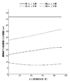
- FIG. 10 shows an example of the relationship between the distance from the reference position of the focus lens system at the wide position and the focal length.
- the reference position is the position of the first focus lens 191, the second focus lens 192, and the cam ring 302 when the focal length is 500 mm.
- the distance from the reference position is expressed as positive on the image plane side and negative on the object side.
- the cam ring 302 moves in a direction opposite to the moving direction of the center of gravity of the object system including the first focus lens 191 and the second focus lens 192.
- the focal length changes from 500 mm toward ⁇
- the cam ring 302 once approaches the imaging plane side, then moves away from the imaging plane side, and then approaches the imaging plane side again. It moves a lot.
- the movement locus shown in FIG. 10 is an example, and the movement locus of the cam ring 302 differs depending on the mass or movement locus of the focus lens.
- FIG. 11 shows an example of the relationship between the physical quantity (moment) (g ⁇ mm) obtained by multiplying the distance from the reference position of the focus lens system at the wide position and the focal length.
- FIG. 12 shows an example of the relationship between the distance from the reference position of the focus lens system at the wide position, the focal length, and the physical quantity (moment) (g ⁇ mm) obtained by multiplying the distance from the reference position by mass.
- the reference position is the position of the first focus lens 191, the second focus lens 192, and the cam ring 302 when the focal length is 500 mm.
- the physical quantity obtained by multiplying the mass of the distance from the reference position is referred to as a physical quantity B x.
- the cam ring 302 moves in a direction that suppresses a change in the position of the center of gravity of the object system including the first focus lens 191 and the second focus lens 192.
- the distance from the reference position of the cam ring 302 is equal to or less than a predetermined value obtained by dividing the sum of the physical quantity B 1 of the first focus lens and the physical quantity B 2 of the second focus lens by the mass of the cam ring 302. It may be set as follows.
- the cam ring 302 always has a total ⁇ B of the physical quantity B x of zero while changing the focal length from the shortest distance (for example, 500 mm) to the longest distance (for example, ⁇ ). Move to become.
- the cam ring 302 is not necessarily the sum ⁇ B physical quantity B x moves always be zero. This is because, for example, the drive region of the groove of the cam ring 302 is restricted due to restrictions such as design.
- the focal length from the shortest distance maximum total ⁇ B physical quantity B x in the case of changing to a maximum distance of 3 minutes when there is no suppression of the change in position of the center of gravity by the cam ring 302 may move so that it is 1 or less.
- the width W of the change in the position of the center of gravity of the lens device 160 is less than 10% when the change in the position of the center of gravity by the cam ring 302 is not suppressed.
- the cam ring 202 may move.
- a driving torque for the pitch axis of the gimbal 110 necessary to keep the optical axis of the lens device 160 horizontal is C (N ⁇ mm).
- the cam ring 302 moves so that the maximum value of the driving torque C when the focal length is changed from the shortest distance to the longest distance is less than 10% when the change in the position of the center of gravity by the cam ring 302 is not suppressed. May be.
- the change in the position of the center of gravity of the lens device 160 due to the movement of the focus lens system is suppressed by the movement of the cam ring 302 in the optical axis direction.
- FIG. 13 shows an example of an external perspective view of the cam ring 202 of the zoom lens system.
- FIG. 14 shows an example of an external perspective view of the fixed cylinder 232.
- the fixed cylinder 232 is fixed to a base 168 on which an electronic circuit such as the image sensor 144 is provided.
- the fixed cylinder 232 holds the lenses of the first lens group 171.
- the cam ring 202 is disposed on the outer peripheral side of the fixed cylinder 232 so as to be rotatable and movable in the optical axis direction.
- a gear 204 is formed on a part of the outer periphery of one end of the cam ring 202.
- the gear 204 meshes with the gear 166.
- the gear 166 is rotated by the drive motor 165. Power from the drive motor 165 is transmitted to the gear 204 via the gear 166, and the cam ring 202 moves along the outer periphery of the fixed cylinder 232 in the optical axis direction while rotating.
- cam ring support pins 234 are provided on the outer peripheral surface of the fixed cylinder 232.
- the cam ring support pin 234 guides the movement of the cam ring 202 in the optical axis direction.
- a straight guide groove 236 is formed in the fixed cylinder 232.
- the rectilinear guide groove 236 guides the movement of the second lens group cam pin 220, the third lens group cam pin 222, and the fourth lens group cam pin (not shown) in the optical axis direction.
- the second lens group cam pin 220 is provided on the lens holding member 230 that holds the lens 170 of the second lens group 172.
- the third lens group cam pin 222 is provided on the lens holding member 230 that holds the lens 170 of the third lens group 173.
- the fourth lens group cam pin is provided on the lens holding member 230 that holds the lens 170 of the fourth lens group 174.
- the cam ring 202 has a cam ring cam groove 212 that engages with the cam ring support pin 234.
- the cam ring cam groove 212 is guided by the cam ring support pin 234, so that the cam ring 202 moves in the optical axis direction while rotating.
- the cam ring 202 moves in the direction of the arrow 132 while rotating in the direction of the arrow 130.
- the cam ring 202 further includes a second lens group cam groove 214 that engages with the second lens group cam pin 220, a third lens group cam groove 216 that engages with the third lens group cam pin 222, and a fourth lens.
- a fourth lens group cam groove (not shown) that engages with the group cam pins is formed.
- the second lens group cam pin 220 moves in the rectilinear guide groove 236 along the second lens group cam groove 214.
- the lenses of the second lens group 172 move in the optical axis direction.
- the third lens group cam pin 222 moves in the straight guide groove 236 along the third lens group cam groove 216.
- the lenses of the third lens group 173 move in the optical axis direction.
- the fourth lens group cam pin moves in the straight guide groove 236 along the fourth lens group cam groove.
- the lenses of the fourth lens group 174 move in the optical axis direction.
- the cam ring 202 is an example of the moving member 200.
- the straight guide groove 236, the cam ring cam groove 212, the second lens group cam groove 214, the third lens group cam groove 216, and the fourth lens group cam groove are examples of the second cam portion.
- the side surfaces of the rectilinear guide groove 236, the cam ring cam groove 212, the second lens group cam groove 214, the third lens group cam groove 216, and the fourth lens group cam groove are cams of the second cam portion. It is an example of a surface.
- the cam ring support pin 234, the second lens group cam pin 220, the third lens group cam pin 222, and the fourth lens group cam pin are examples of the second follower portion.
- the cam ring 202 moves in a direction opposite to the moving direction of the center of gravity of the object system including the lenses of the second lens group 172, the third lens group 173, and the fourth lens group 174. More specifically, the center of gravity of the object system in which the cam ring 202 includes the lens of the second lens group 172, the lens of the third lens group 173, the lens of the fourth lens group 174, and the light amount adjustment mechanism 180 having the diaphragm 182 and the actuator. Move in the direction opposite to the direction of movement. Thereby, the change in the position of the center of gravity of the lens device 160 accompanying the zoom operation can be suppressed.
- FIG. 15 shows an example of the relationship between the cam ring rotation angle and the distance from the imaging plane of the image sensor 144.
- the cam ring rotation angle is a rotation angle from the reference angle of the cam ring 202 when the rotation angle of the cam ring 202 at the wide end of the lens device 160 is a reference angle (0 degree).
- the distance from the imaging plane of the image sensor 144 is the distance from the imaging plane of the image sensor 144 to each lens group of the zoom lens system.
- FIG. 15 shows how the distance from the imaging surface of the image sensor 144 to each lens group of the zoom lens system changes when the lens device 160 is changed from the wide end to the tele end.
- FIG. 16 shows an example of the relationship between the cam ring rotation angle and the distance from the wide position.
- the wide position is the position of each lens group of the zoom lens system and the cam ring 202 at the wide end of the lens device 160.
- FIG. 16 shows changes in the distance from the wide position of each lens group of the zoom lens system and the cam ring 202 when the lens device 160 is changed from the wide end to the tele end.
- FIG. 17 shows an example of the relationship between the cam rotation angle and the physical quantity (g ⁇ mm) obtained by multiplying the distance from the wide position by the mass.
- the physical quantity A x the physical quantity obtained by multiplying the mass of the distance from the wide-angle position.
- the cam ring 202 moves in a direction that suppresses a change in the position of the center of gravity of the object system including the second lens group 172, the third lens group 173, and the fourth lens group 174.
- Mass of the third lens group 173 is a parameter of a physical quantity A 3 of the third lens group 173 may include the mass of the diaphragm 182.
- the cam ring 202 while changing the lens apparatus 160 to the telephoto end from the wide-angle end, the sum ⁇ A physical quantity A x moves always be zero. However, the cam ring 202 is not necessarily moved so that the total ⁇ A of the physical quantity A x is always zero. This is because, for example, the drive region of the groove of the cam ring 202 is restricted due to restrictions such as design.
- the cam ring 202 may move so that it becomes 1 or less.
- the width W of the change in the position of the center of gravity of the lens device 160 is less than 10% when the change in the position of the center of gravity by the cam ring 202 is not suppressed.
- the cam ring 202 may move.
- a driving torque for the pitch axis of the gimbal 110 necessary to keep the optical axis of the lens device 160 horizontal is C (N ⁇ mm).
- the cam ring 202 is such that the maximum value of the drive torque C when the lens device 160 is changed from the wide end to the tele end is less than 10% of the case where the change in the position of the center of gravity by the cam ring 202 is not suppressed. You may move.
- the movement of the center of gravity of the lens device 160 due to the zoom operation is suppressed by the movement of the cam ring 202 in the optical axis direction.
- the gimbal 110 preferably holds the imaging device 140 and the lens device 160 so as to be rotatable on a pitch axis passing through the center of gravity of the object system including the imaging device 140 and the lens device 160. As shown in FIGS. 18, 19, and 20, the gimbal 110 can hold the imaging device 140 and the lens device 160 in various postures by rotating around the pitch axis.
- the lens device 160 performs a zoom operation and a focus operation in various postures. However, the position of the center of gravity of the lens device 160 does not change due to the zoom operation and the focus operation.
- the imaging device 140 and the lens can be operated even when the lens device 160 performs the zoom operation and the focusing operation in various postures.
- the position of the center of gravity of the object system including the device 160 can be maintained on the pitch axis. Therefore, the driving torque of the pitch axis rotation mechanism 112 does not change due to the difference in the zoom position and focus operation of the lens device 160.
- the pitch axis of the gimbal 110 does not necessarily pass through the center of gravity of the object system including the imaging device 140 and the lens device 160.
- the pitch axis of the gimbal 110 may be set so as to be located within a predetermined range with respect to the center of gravity of the object system including the imaging device 140 and the lens device 160.
- the predetermined range may be a range from the center of gravity of the object system to a distance (H / 4) that is a quarter of the total length (H) of the object system, as shown in FIG.
- FIG. 21 is an external perspective view showing an example of the stabilizer 800.
- the UAV 10 equipped with the imaging device 140 and the lens device 160 has been described.
- the imaging device 140 and the lens device 160 may not be mounted on the UAV 10. It may be mounted on a moving body other than the imaging device 140, the lens device 160, and the UAV10.
- the camera unit 813 mounted on the stabilizer 800 corresponds to the imaging device 140 and the lens device 160.
- the stabilizer 800 includes a camera unit 813, a gimbal 820, and a handle portion 803.
- the gimbal 820 supports the camera unit 813 in a rotatable manner.
- the gimbal 820 has a pan axis 809, a roll axis 810, and a tilt axis 811.
- the gimbal 820 supports the camera unit 813 so as to be rotatable about a pan axis 809, a roll axis 810, and a tilt axis 811.
- the gimbal 820 is an example of a support mechanism.
- the camera unit 813 is an example of a lens device or a lens device and an imaging device.
- the camera unit 813 has a slot 812 for inserting a memory.
- the gimbal 820 is fixed to the handle portion 803 via the holder 807.
- the handle portion 803 has various buttons for operating the gimbal 820 and the camera unit 813.
- the handle portion 803 includes a shutter button 804, a recording button 805, and an operation button 806. By pressing the shutter button 804, a still image can be recorded by the camera unit 813.
- the recording button 805 is pressed, a moving image can be recorded by the camera unit 813.
- the device holder 801 is fixed to the handle portion 803.
- the device holder 801 holds a mobile device 802 such as a smartphone.
- the mobile device 802 is communicably connected to the stabilizer 800 via a wireless network such as WiFi. Thereby, an image captured by the camera unit 813 can be displayed on the screen of the mobile device 802.
Abstract
Description
特許文献1 特開平08-022068号公報
特許文献2 特開2010-39350号公報 Patent Document 1 discloses a camera stabilizer that moves an auxiliary balance weight in a direction opposite to a moving direction of a lens by a zoom operation or a focus operation.
Patent Document 1 Japanese Patent Application Laid-Open No. 08-022068
102 通信インタフェース
104 UAV制御部
106 メモリ
110 ジンバル
112 ピッチ軸回転機構
114 ロール軸回転機構
116 ヨー軸回転機構
140 撮像装置
142 撮像制御部
144 撮像素子
146 メモリ
160 レンズ装置
161 メモリ
162 レンズ制御部
164 駆動機構
165 駆動モータ
166 ギア
168 基台
170 レンズ
171 第1レンズ群
172 第2レンズ群
173 第3レンズ群
174 第4レンズ群
180 光量調整機構
190 レンズ
191 第1フォーカスレンズ
192 第2フォーカスレンズ
194 駆動機構
195 レンズ保持部材
196 レンズ保持部材
200 移動部材
202 カム環
204 ギア
210 物理的構造体
212 カム環用カム溝
214 第2レンズ群用カム溝
216 第3レンズ群用カム溝
220 第2レンズ群カムピン
222 第3レンズ群カムピン
230 レンズ保持部材
232 固定筒
234 カム環支持ピン
236 直進案内溝
300 移動部材
301 固定筒
302 カム環
306 ギア機構
307 駆動モータ
310 物理的構造体
311 カム環用カムピン
312 カム環用カム溝
313 第1フォーカスレンズ用カムピン
314 第1フォーカスレンズ用カム溝
315 第2フォーカスレンズ用カムピン
316 第2フォーカスレンズ用カム溝
319 ギア
321 ガイド支柱
322 ガイド支柱
330 レンズ保持部材
800 スタビライザ
801 デバイスホルダ
802 モバイルデバイス
803 持ち手部
804 シャッターボタン
805 録画ボタン
806 操作ボタン
807 ホルダ
812 スロット
813 カメラユニット
820 ジンバル 101 UAV body 102 Communication interface 104 UAV control unit 106 Memory 110 Gimbal 112 Pitch axis rotation mechanism 114 Roll axis rotation mechanism 116 Yaw axis rotation mechanism 140 Imaging device 142 Imaging control unit 144 Imaging element 146 Memory 160 Lens device 161 Memory 162 Lens control unit 164 Drive mechanism 165 Drive motor 166 Gear 168 Base 170 Lens 171 First lens group 172 Second lens group 173 Third lens group 174 Fourth lens group 180 Light amount adjustment mechanism 190 Lens 191 First focus lens 192 Second focus lens 194 Drive mechanism 195 Lens holding member 196 Lens holding member 200 Moving member 202 Cam ring 204 Gear 210 Physical structure 212 Cam ring cam groove 214 Second lens group cam groove 216 Third lens group Groove 220 Second lens group cam pin 222 Third lens group cam pin 230 Lens holding member 232 Fixed cylinder 234 Cam ring support pin 236 Straight guide groove 300 Moving member 301 Fixed cylinder 302 Cam ring 306 Gear mechanism 307 Drive motor 310 Physical structure 311 Cam ring cam pin 312 Cam ring cam groove 313 First focus lens cam pin 314 First focus lens cam groove 315 Second focus lens cam pin 316 Second focus lens cam groove 319 Gear 321 Guide column 322 Guide column 330 Lens holding member 800 Stabilizer 801 Device holder 802 Mobile device 803 Handle 804 Shutter button 805 Recording button 806 Operation button 807 Holder 812 Slot 813 Camera unit 820 Gimbal
Claims (21)
- 1又は複数の第1レンズを含み、焦点距離を調整する第1レンズ系と、
1又は複数の第2レンズを含む第2レンズ系と、
前記1又は複数の第1レンズの光軸方向に移動可能な第1移動部材と、
前記1又は複数の第1レンズを前記光軸方向に移動させるとともに、前記1又は複数の第1レンズを含む物体系の重心の移動方向の反対方向に前記第1移動部材を移動させる第1物理的構造体と
を備えるレンズ装置。 A first lens system including one or more first lenses and adjusting a focal length;
A second lens system including one or more second lenses;
A first moving member movable in the optical axis direction of the one or more first lenses;
First physics that moves the one or more first lenses in the optical axis direction and moves the first moving member in a direction opposite to the moving direction of the center of gravity of the object system including the one or more first lenses. Device comprising a mechanical structure. - 前記1又は複数の第1レンズを保持する第1レンズ保持部材
をさらに備え、
前記第1物理的構造体は、
前記第1レンズ保持部材及び前記第1移動部材の一方に設けられた第1カム部と、
前記第1レンズ保持部材及び前記第1移動部材の他方に設けられ、前記第1カム部のカム面に沿って移動することにより前記第1レンズ保持部材と前記第1移動部材とを相対的に移動させる第1フォロア部と
を有する、請求項1に記載のレンズ装置。 A first lens holding member that holds the one or more first lenses;
The first physical structure is:
A first cam portion provided on one of the first lens holding member and the first moving member;
Provided on the other of the first lens holding member and the first moving member, and moving along the cam surface of the first cam portion, the first lens holding member and the first moving member are relatively moved. The lens device according to claim 1, further comprising a first follower section that is moved. - 前記第1移動部材は、第1カム環である、請求項2に記載のレンズ装置。 The lens device according to claim 2, wherein the first moving member is a first cam ring.
- 前記第1移動部材は、前記1又は複数の第1レンズより比重が大きな材料である、請求項1に記載のレンズ装置。 The lens device according to claim 1, wherein the first moving member is a material having a specific gravity greater than that of the one or more first lenses.
- 前記第1移動部材は、金属である、請求項1に記載のレンズ装置。 The lens device according to claim 1, wherein the first moving member is a metal.
- 前記第2レンズ系は、単焦点レンズ系である、請求項1から4のいずれか1つに記載のレンズ装置。 The lens device according to any one of claims 1 to 4, wherein the second lens system is a single focus lens system.
- 前記第2レンズ系は、ズームレンズ系であり、
前記レンズ装置は、
前記1又は複数の第2レンズの光軸方向に移動可能な第2移動部材と、
前記1又は複数の第2レンズを前記光軸方向に移動させるとともに、前記1又は複数の第2レンズを含む物体系の重心の移動方向の反対方向に前記第2移動部材を移動させる第2物理的構造体と
を備える、請求項1から4のいずれか1つに記載のレンズ装置。 The second lens system is a zoom lens system;
The lens device is
A second moving member movable in the optical axis direction of the one or more second lenses;
Second physics that moves the one or more second lenses in the optical axis direction and moves the second moving member in a direction opposite to the direction of movement of the center of gravity of the object system including the one or more second lenses. The lens device according to claim 1, comprising a mechanical structure. - 前記1又は複数の第2レンズを保持する第2レンズ保持部材
をさらに備え、
前記第2物理的構造体は、
前記第2レンズ保持部材及び前記第2移動部材の一方に設けられた第2カム部と、
前記第2レンズ保持部材及び前記第1移動部材の他方に設けられ、前記第2カム部のカム面に沿って移動することにより前記第2レンズ保持部材と前記第2移動部材とを相対的に移動させる第1フォロア部と
を有する、請求項7に記載のレンズ装置。 A second lens holding member that holds the one or more second lenses;
The second physical structure is:
A second cam portion provided on one of the second lens holding member and the second moving member;
Provided on the other of the second lens holding member and the first moving member, and moving along the cam surface of the second cam portion, the second lens holding member and the second moving member are relatively moved. The lens device according to claim 7, further comprising a first follower section that is moved. - 前記第2移動部材は、カム環である、請求項8に記載のレンズ装置。 The lens device according to claim 8, wherein the second moving member is a cam ring.
- 前記第2移動部材は、前記1又は複数のレンズより比重が大きな材料である、請求項7に記載のレンズ装置。 The lens device according to claim 7, wherein the second moving member is made of a material having a specific gravity greater than that of the one or more lenses.
- 前記第2移動部材は、金属である、請求項7に記載のレンズ装置。 The lens device according to claim 7, wherein the second moving member is a metal.
- 前記1又は複数の第1レンズのうちの一部のレンズとともに移動し、前記1又は複数の第1レンズを通過する光量を調整する光量調整機構
をさらに備え、
前記第2物理的構造体は、前記光量調整機構をさらに含む物体系の重心の移動方向の反対方向に前記移動部材を移動させる、請求項7に記載のレンズ装置。 A light amount adjusting mechanism that moves together with some of the one or more first lenses and adjusts the amount of light passing through the one or more first lenses;
The lens apparatus according to claim 7, wherein the second physical structure moves the moving member in a direction opposite to a moving direction of a center of gravity of an object system further including the light amount adjusting mechanism. - 前記光量調整機構は、
開口径が変更可能な絞りと、
前記絞りを駆動して前記開口径を変更するアクチュエータと
を有する、請求項12に記載のレンズ装置。 The light amount adjustment mechanism is
An aperture with a variable aperture diameter,
The lens apparatus according to claim 12, further comprising an actuator that drives the diaphragm to change the opening diameter. - 請求項1に記載のレンズ装置と、
前記レンズ装置によって結像された光を撮像する撮像装置と
を備える撮像システム。 A lens device according to claim 1;
An imaging system comprising: an imaging device that images light imaged by the lens device. - 前記レンズ装置及び前記撮像装置の少なくとも一方を支持する支持機構
をさらに備える請求項14に記載の撮像システム。 The imaging system according to claim 14, further comprising a support mechanism that supports at least one of the lens device and the imaging device. - 前記支持機構は、前記レンズ装置及び前記撮像装置を、前記レンズ装置及び前記撮像装置を含む物体系の重心から予め定められた距離の範囲内を通る回転軸で回転可能に支持する、請求項15に記載の撮像システム。 The support mechanism supports the lens device and the imaging device so that the lens device and the imaging device can rotate on a rotation axis passing through a predetermined distance from a center of gravity of an object system including the lens device and the imaging device. The imaging system described in 1.
- 前記支持機構は、前記レンズ装置及び前記撮像装置を、前記レンズ装置及び前記撮像装置を含む物体系の重心を通る回転軸で回転可能に支持する、請求項16に記載の撮像システム。 The imaging system according to claim 16, wherein the support mechanism supports the lens device and the imaging device so as to be rotatable on a rotation axis passing through a center of gravity of an object system including the lens device and the imaging device.
- 請求項15に記載の撮像システムを備えて移動する移動体。 A moving body that moves with the imaging system according to claim 15.
- 前記移動体は無人航空機である、請求項18に記載の移動体。 The mobile body according to claim 18, wherein the mobile body is an unmanned aerial vehicle.
- 前記支持機構に取り付けられている持ち手部
をさらに備える、請求項15に記載の撮像システム。 The imaging system according to claim 15, further comprising a handle portion attached to the support mechanism. - 1又は複数の第1レンズを含み、焦点距離を調整する第1レンズ系と、1又は複数の第2レンズを含む第2レンズ系、前記1又は複数の第1レンズの光軸方向に移動可能な第1移動部材とを備えるレンズ装置の制御方法であって、
第1物理的構造体よって、前記1又は複数の第1レンズを前記光軸方向に移動させるとともに、前記1又は複数の第1レンズを含む物体系の重心の移動方向の反対方向に前記第1移動部材を移動させる段階
を備える制御方法。 A first lens system including one or a plurality of first lenses and adjusting a focal length, a second lens system including one or a plurality of second lenses, and movable in the optical axis direction of the one or a plurality of first lenses A control method of a lens device comprising a first moving member,
The first physical structure moves the one or more first lenses in the optical axis direction, and the first physical structure in the direction opposite to the moving direction of the center of gravity of the object system including the one or more first lenses. A control method comprising a step of moving a moving member.
Priority Applications (3)
| Application Number | Priority Date | Filing Date | Title |
|---|---|---|---|
| PCT/JP2016/081696 WO2018078736A1 (en) | 2016-10-26 | 2016-10-26 | Lens device, image pickup system, mobile body, and control method |
| JP2017559883A JP6528255B2 (en) | 2016-10-26 | 2016-10-26 | Lens apparatus, imaging system, moving object, and control method |
| US16/386,642 US11307374B2 (en) | 2016-10-26 | 2019-04-17 | Lens device, imaging system, movable object, and control method |
Applications Claiming Priority (1)
| Application Number | Priority Date | Filing Date | Title |
|---|---|---|---|
| PCT/JP2016/081696 WO2018078736A1 (en) | 2016-10-26 | 2016-10-26 | Lens device, image pickup system, mobile body, and control method |
Related Child Applications (1)
| Application Number | Title | Priority Date | Filing Date |
|---|---|---|---|
| US16/386,642 Continuation US11307374B2 (en) | 2016-10-26 | 2019-04-17 | Lens device, imaging system, movable object, and control method |
Publications (1)
| Publication Number | Publication Date |
|---|---|
| WO2018078736A1 true WO2018078736A1 (en) | 2018-05-03 |
Family
ID=62023230
Family Applications (1)
| Application Number | Title | Priority Date | Filing Date |
|---|---|---|---|
| PCT/JP2016/081696 WO2018078736A1 (en) | 2016-10-26 | 2016-10-26 | Lens device, image pickup system, mobile body, and control method |
Country Status (3)
| Country | Link |
|---|---|
| US (1) | US11307374B2 (en) |
| JP (1) | JP6528255B2 (en) |
| WO (1) | WO2018078736A1 (en) |
Cited By (1)
| Publication number | Priority date | Publication date | Assignee | Title |
|---|---|---|---|---|
| JP2021018396A (en) * | 2019-07-24 | 2021-02-15 | エスゼット ディージェイアイ テクノロジー カンパニー リミテッドSz Dji Technology Co.,Ltd | Control device, imaging system, moving body, control method, and program |
Families Citing this family (2)
| Publication number | Priority date | Publication date | Assignee | Title |
|---|---|---|---|---|
| JP7005177B2 (en) * | 2017-06-02 | 2022-02-10 | キヤノン株式会社 | Imaging device and mobile body |
| WO2021028009A1 (en) * | 2019-08-09 | 2021-02-18 | Ficomirrors S.A.U | Camera module for vehicles |
Citations (3)
| Publication number | Priority date | Publication date | Assignee | Title |
|---|---|---|---|---|
| JPS58154822A (en) * | 1982-03-10 | 1983-09-14 | Fuji Photo Optical Co Ltd | Preventing mechanism for natural movement of zoom lens |
| JP2010283610A (en) * | 2009-06-04 | 2010-12-16 | Tamagawa Seiki Co Ltd | Spatial stabilizer |
| JP2012048178A (en) * | 2010-08-30 | 2012-03-08 | Fujifilm Corp | Lens device and television camera |
Family Cites Families (7)
| Publication number | Priority date | Publication date | Assignee | Title |
|---|---|---|---|---|
| US5162831A (en) * | 1986-05-12 | 1992-11-10 | Asahi Kogaku Kogyo Kabushiki Kaisha | Zoom lens drive system for camera |
| JPH0822068A (en) * | 1994-07-05 | 1996-01-23 | Japan Aviation Electron Ind Ltd | Camera stabilizer |
| US6130705A (en) * | 1998-07-10 | 2000-10-10 | Recon/Optical, Inc. | Autonomous electro-optical framing camera system with constant ground resolution, unmanned airborne vehicle therefor, and methods of use |
| US8137007B1 (en) * | 2008-01-11 | 2012-03-20 | Brandebury Tool Company, Inc. | Miniaturized turret-mounted camera assembly |
| JP2010039350A (en) * | 2008-08-07 | 2010-02-18 | Tamagawa Seiki Co Ltd | Structure for adjusting weight balance of space stabilizing device |
| IL199009A (en) * | 2009-05-27 | 2013-11-28 | Israel Aerospace Ind Ltd | Air vehicle |
| US9156551B2 (en) * | 2011-08-29 | 2015-10-13 | Aerovironment, Inc. | Tilt-ball turret with gimbal lock avoidance |
-
2016
- 2016-10-26 JP JP2017559883A patent/JP6528255B2/en not_active Expired - Fee Related
- 2016-10-26 WO PCT/JP2016/081696 patent/WO2018078736A1/en active Application Filing
-
2019
- 2019-04-17 US US16/386,642 patent/US11307374B2/en active Active
Patent Citations (3)
| Publication number | Priority date | Publication date | Assignee | Title |
|---|---|---|---|---|
| JPS58154822A (en) * | 1982-03-10 | 1983-09-14 | Fuji Photo Optical Co Ltd | Preventing mechanism for natural movement of zoom lens |
| JP2010283610A (en) * | 2009-06-04 | 2010-12-16 | Tamagawa Seiki Co Ltd | Spatial stabilizer |
| JP2012048178A (en) * | 2010-08-30 | 2012-03-08 | Fujifilm Corp | Lens device and television camera |
Cited By (1)
| Publication number | Priority date | Publication date | Assignee | Title |
|---|---|---|---|---|
| JP2021018396A (en) * | 2019-07-24 | 2021-02-15 | エスゼット ディージェイアイ テクノロジー カンパニー リミテッドSz Dji Technology Co.,Ltd | Control device, imaging system, moving body, control method, and program |
Also Published As
| Publication number | Publication date |
|---|---|
| US20190243085A1 (en) | 2019-08-08 |
| JP6528255B2 (en) | 2019-06-12 |
| US11307374B2 (en) | 2022-04-19 |
| JPWO2018078736A1 (en) | 2018-10-25 |
Similar Documents
| Publication | Publication Date | Title |
|---|---|---|
| JP6018331B1 (en) | LENS DEVICE, IMAGING SYSTEM, MOBILE BODY, AND CONTROL METHOD | |
| JP6582315B2 (en) | Lens system, imaging device, moving body and system | |
| CN110366693B (en) | Lens system, imaging device, and moving object | |
| US11307374B2 (en) | Lens device, imaging system, movable object, and control method | |
| JP6720454B1 (en) | Lens system, imaging device, and moving body | |
| JP6450950B2 (en) | Zoom lens, imaging device, moving object, and system | |
| WO2018189818A1 (en) | Lens system, image pickup device, mobile body, and system | |
| CN110325889B (en) | Lens device, imaging device, and moving object | |
| JP6596740B2 (en) | Lens device, imaging system, moving object | |
| JP6318427B2 (en) | LENS DEVICE, IMAGING SYSTEM, MOBILE BODY, AND CONTROL METHOD | |
| JP6561369B2 (en) | Lens system, imaging device, moving body and system | |
| JP6532044B2 (en) | Zoom lens, imaging device, moving object and system | |
| WO2018134926A1 (en) | Optical device, moving body, and system | |
| JP2019095487A (en) | Lens device, imaging apparatus, and mobile body | |
| JP6443567B2 (en) | Zoom lens, imaging device, moving object, and system | |
| JP6565073B2 (en) | Optical system and moving body | |
| CN112334813A (en) | Lens system, imaging device, and moving object | |
| JP6543876B2 (en) | CONTROL DEVICE, IMAGING SYSTEM, MOBILE OBJECT, CONTROL METHOD, AND PROGRAM | |
| CN112334812A (en) | Lens system, imaging device, and moving object | |
| JP2012230433A (en) | Lens barrel |
Legal Events
| Date | Code | Title | Description |
|---|---|---|---|
| WWE | Wipo information: entry into national phase |
Ref document number: 2017559883 Country of ref document: JP |
|
| 121 | Ep: the epo has been informed by wipo that ep was designated in this application |
Ref document number: 16920137 Country of ref document: EP Kind code of ref document: A1 |
|
| NENP | Non-entry into the national phase |
Ref country code: DE |
|
| 32PN | Ep: public notification in the ep bulletin as address of the adressee cannot be established |
Free format text: NOTING OF LOSS OF RIGHTS PURSUANT TO RULE 112(1) EPC (EPO FORM 1205N DATED 20/08/2019) |
|
| 122 | Ep: pct application non-entry in european phase |
Ref document number: 16920137 Country of ref document: EP Kind code of ref document: A1 |