WO2018074299A1 - 計測装置および血液循環装置 - Google Patents
計測装置および血液循環装置 Download PDFInfo
- Publication number
- WO2018074299A1 WO2018074299A1 PCT/JP2017/036806 JP2017036806W WO2018074299A1 WO 2018074299 A1 WO2018074299 A1 WO 2018074299A1 JP 2017036806 W JP2017036806 W JP 2017036806W WO 2018074299 A1 WO2018074299 A1 WO 2018074299A1
- Authority
- WO
- WIPO (PCT)
- Prior art keywords
- light
- tube
- light emitting
- fixing member
- blood
- Prior art date
- Legal status (The legal status is an assumption and is not a legal conclusion. Google has not performed a legal analysis and makes no representation as to the accuracy of the status listed.)
- Ceased
Links
Images






Classifications
-
- A—HUMAN NECESSITIES
- A61—MEDICAL OR VETERINARY SCIENCE; HYGIENE
- A61M—DEVICES FOR INTRODUCING MEDIA INTO, OR ONTO, THE BODY; DEVICES FOR TRANSDUCING BODY MEDIA OR FOR TAKING MEDIA FROM THE BODY; DEVICES FOR PRODUCING OR ENDING SLEEP OR STUPOR
- A61M1/00—Suction or pumping devices for medical purposes; Devices for carrying-off, for treatment of, or for carrying-over, body-liquids; Drainage systems
- A61M1/36—Other treatment of blood in a by-pass of the natural circulatory system, e.g. temperature adaptation, irradiation ; Extra-corporeal blood circuits
-
- G—PHYSICS
- G01—MEASURING; TESTING
- G01N—INVESTIGATING OR ANALYSING MATERIALS BY DETERMINING THEIR CHEMICAL OR PHYSICAL PROPERTIES
- G01N21/00—Investigating or analysing materials by the use of optical means, i.e. using sub-millimetre waves, infrared, visible or ultraviolet light
- G01N21/17—Systems in which incident light is modified in accordance with the properties of the material investigated
- G01N21/25—Colour; Spectral properties, i.e. comparison of effect of material on the light at two or more different wavelengths or wavelength bands
- G01N21/31—Investigating relative effect of material at wavelengths characteristic of specific elements or molecules, e.g. atomic absorption spectrometry
- G01N21/35—Investigating relative effect of material at wavelengths characteristic of specific elements or molecules, e.g. atomic absorption spectrometry using infrared light
- G01N21/3577—Investigating relative effect of material at wavelengths characteristic of specific elements or molecules, e.g. atomic absorption spectrometry using infrared light for analysing liquids, e.g. polluted water
-
- G—PHYSICS
- G01—MEASURING; TESTING
- G01N—INVESTIGATING OR ANALYSING MATERIALS BY DETERMINING THEIR CHEMICAL OR PHYSICAL PROPERTIES
- G01N21/00—Investigating or analysing materials by the use of optical means, i.e. using sub-millimetre waves, infrared, visible or ultraviolet light
- G01N21/17—Systems in which incident light is modified in accordance with the properties of the material investigated
- G01N21/25—Colour; Spectral properties, i.e. comparison of effect of material on the light at two or more different wavelengths or wavelength bands
- G01N21/31—Investigating relative effect of material at wavelengths characteristic of specific elements or molecules, e.g. atomic absorption spectrometry
- G01N21/35—Investigating relative effect of material at wavelengths characteristic of specific elements or molecules, e.g. atomic absorption spectrometry using infrared light
- G01N21/359—Investigating relative effect of material at wavelengths characteristic of specific elements or molecules, e.g. atomic absorption spectrometry using infrared light using near infrared light
Definitions
- the present invention relates to a measuring apparatus, and more particularly to an apparatus for measuring blood circulating in a tube and a substance in the blood and a blood circulating apparatus.
- Patent Document 1 discloses a biological information reading apparatus that constantly obtains information on a person's pulse wave and blood pressure.
- This biological information reading apparatus includes a biological signal acquisition unit that acquires a biological signal from a living body, and a calculation unit that performs an operation of estimating biological information based on the acquired biological signal that is a biological signal acquired by the biological signal acquisition unit. And a biometric information output unit that outputs estimated biometric information, which is biometric information estimated by the calculation unit, to the outside of the biometric information reader.
- Patent Document 2 discloses a blood purification apparatus and a blood flow calculation method for the blood purification apparatus capable of obtaining the actual blood flow circulating extracorporeally in the blood circuit in a short time and accurately regardless of the individual difference of the detection means. ing.
- This blood purification apparatus includes detection means capable of detecting a blood concentration index of a patient circulating extracorporeally in a blood circuit.
- the blood is circulated through the tube and returned to the body.
- it is important to accurately grasp the state of blood flowing in the tube.
- various information regarding blood and substances in blood can be continuously measured in a short time.
- An object of the present invention is to provide a measuring apparatus and a blood circulating apparatus capable of accurately and continuously measuring the state of blood circulating in a tube or the state of a substance in blood.
- one embodiment of the present invention is a measurement device that measures the state of blood circulating in a tube or the state of a substance in blood, and has an emission wavelength of 806 nanometers (nm) or more and 855 nm or less.
- a light emitting unit including a first light emitting element that irradiates the blood with light including the first near infrared light, a light receiving unit that receives the first near infrared light via blood, and the light emitting unit and the light receiving unit on the outside of the tube And a fixing part for attaching to the measuring device.
- various information related to blood can be acquired by light including first near infrared light having a wavelength of 806 nm or more and 855 nm or less.
- first near infrared light having a wavelength of 806 nm or more and 855 nm or less.
- the light emitting unit and the light receiving unit are securely attached to the tube, it is possible to perform highly accurate measurement even when attached to the tube.
- the light emitting unit includes a second light emitting element that irradiates the blood with light including second near infrared light having an emission wavelength of 755 nm to 765 nm, and the light receiving unit receives the second near infrared light. May be.
- the first near-infrared light with a wavelength of 806 nm to 855 nm
- the second near-infrared light with a wavelength of 755 nm to 765 nm
- the fixing portion may be composed of a plurality of members, and the tube may be sandwiched between the plurality of members.
- the plurality of members may include a first fixing member and a second fixing member, and the first fixing member may include a tube receiving portion that receives the tube.
- the light emitting unit and the light receiving unit may be integrated, and the second fixing member may have the light receiving / emitting unit.
- the reflective sensor which irradiates light to the blood which passes the inside of a tube from the light-receiving / emitting part of a 2nd fixing member, and detects the reflected light can be comprised.
- the first fixing member may be opaque to the wavelength of light received and emitted by the light emitting and receiving unit. Thereby, the influence of disturbance light with respect to the light received and emitted by the light emitting / receiving unit can be suppressed.
- the second fixing member may have an intermediate member that forms a flat surface between the tube and the light emitting and receiving unit. This flat surface can stabilize the optical refractive index change between the tube and the light emitting / receiving unit, and can perform highly accurate measurement.
- the first fixing member may have one of a light emitting unit and a light receiving unit
- the second fixing member may have the other of the light emitting unit and the light receiving unit. Accordingly, it is possible to configure a transmissive sensor that performs measurement by transmitting light to blood passing through the tube sandwiched between the first fixing member and the second fixing member.
- the first fixing member and the second fixing member may be opaque to the wavelength of light received and emitted by the light receiving unit and the light emitting unit. Thereby, the influence of the disturbance light with respect to the light received and emitted by the light receiving part and the light emitting part can be suppressed.
- the first fixing member includes a first intermediate member that forms a flat surface between one of the light emitting unit and the light receiving unit and the tube
- the second fixing member includes the tube and the light receiving and emitting unit.
- the fixing unit may have a clip mechanism that maintains a state in which the tube is held at a predetermined pressure between the first fixing member and the second fixing member.
- a light shielding part may be provided before and after the blood flow direction of the tube around the light receiving part. This light shielding part can suppress disturbance light from entering the light receiving part, and can perform highly accurate measurement.
- the measuring device may further include a pressure sensor that detects a contact pressure between the fixed portion and the tube.
- This pressure sensor can maintain an appropriate contact pressure between the fixed portion and the tube.
- you may further provide the temperature sensor which measures external temperature. This temperature sensor can compensate the measurement result with respect to the outside air temperature.
- the measurement device may further include a control unit that controls timing of light emission by the light emitting unit and light reception by the light receiving unit, and performs processing for estimating information related to blood based on a signal output from the light receiving unit. .
- the apparatus which estimates the information relevant to blood can be integrated in a blood circulation apparatus.
- One embodiment of the present invention is a blood circulation device having a tube through which blood circulates, and one of the measurement devices described above attached to the outside of the tube. Thereby, various information relating to blood flowing in the tube from the outside of the tube in the blood circulation device can be acquired.
- the present invention it is possible to provide a measuring apparatus capable of accurately and continuously measuring the state of blood flowing in a tube or the state of a substance in blood.
- FIG. 1 is a perspective view illustrating a measurement apparatus according to this embodiment.
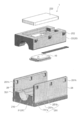
- FIG. 2 is an exploded perspective view of the measuring apparatus according to the present embodiment.
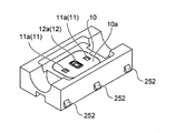
- 3A and 3B are diagrams illustrating the configuration of the sensor module.
- the measuring device 1 is a device that measures the state of blood circulating in the tube T or a substance in the blood, and is used with the tube T interposed therebetween.
- the measuring device 1 includes a sensor module 10 including a light emitting unit 11 and a light receiving unit 12, and a fixing unit 20 for attaching the sensor module 10 to the tube T.
- the fixing unit 20 includes a first fixing member 21 and a second fixing member 22 that are a plurality of members.
- the first fixing member 21 has a tube receiving part 210 that receives the tube T.
- the second fixing member 22 is fixed so as to overlap the first fixing member 21.
- a clip mechanism 25 may be provided between the first fixing member 21 and the second fixing member 22.
- the clip mechanism 25 can be easily fixed and separated in a state where the first fixing member 21 and the second fixing member 22 are overlapped.
- the sensor module 10 is attached to the second fixing member 22, and the light emitting / receiving surface 10a of the light emitting unit 11 and the light receiving unit 12 is arranged on the first fixing member 21 side, that is, the tube T side.
- the sensor module 10 is housed, for example, from above the second fixing member 22 and is pressed by the cover 222. It is preferable to provide a seal (O-ring or the like) between the cover 222 and the second fixing member 22.
- FIG. 3A shows a perspective view with the back side of the second fixing member 22 (the first fixing member 21 side) facing up.
- a pair of light emitting elements 11 a of the light emitting unit 11 and a light receiving element 12 a of the light receiving unit 12 are arranged side by side on the light receiving and emitting surface 10 a.
- the alignment direction (sensor alignment direction) of the pair of light emitting elements 11a of the light emitting unit 11 and the light receiving element 12a of the light receiving unit 12 is along the direction of the tube T (blood flow direction), blood and the light receiving / emitting unit
- the position with 15 can be brought close to and measured.
- the sensor arrangement direction may be along the width direction of the tube T.
- the light emitting unit 11 includes a first light emitting element 11a1 that emits light including first near infrared light having an emission wavelength of 806 nm or more and 855 nm or less.
- the light emitting unit 11 may include a second light emitting element 11a2 that emits light including second near infrared light having an emission wavelength of 755 nm to 765 nm, preferably 758 nm to 762 nm.
- the first light emitting element 11a1 and the second light emitting element 11a2 are light emitting diode elements or laser elements.
- the light emitting unit 11 is configured to emit the first near-infrared light and the second near-infrared light, but may be configured to emit at least the first near-infrared light.
- the first near-infrared light and the second near-infrared light emitted from the light emitting unit 11 are irradiated from the outside of the tube T toward the blood flowing in the tube T.
- the light receiving unit 12 includes a light receiving element 12a that receives first near-infrared light emitted from the light emitting unit 11 and flows through the blood flowing in the tube T and converts the light into an electrical signal.
- the light receiving element 12a is, for example, a photodiode.
- the light receiving element 12a has a sensitivity to receive not only the first near-infrared light but also the second near-infrared light and output an electrical signal corresponding to the amount of received light.
- FIG. 3B is a block diagram illustrating the configuration of the sensor module 10.
- the sensor module 10 includes a light emitting unit 11, a light receiving unit 12, a control unit 13, and an input / output interface unit 14.
- the light emitting unit 11 includes a drive circuit 11b that drives the first light emitting element 11a1 and the second light emitting element 11a2.
- the light receiving unit 12 includes an amplification circuit 12b that amplifies a light reception signal output from the light receiving element 12a. These circuits may be formed into chips.
- the control unit 13 is composed of a microcomputer.
- the control unit 13 can transmit a timing signal to the drive circuit 11b of the light emitting unit 11 and control to emit near infrared light from the first light emitting element 11a1 and the second light emitting element 11a2.
- the control unit 13 converts the amplified received light signal output from the amplification circuit 12b of the light receiving unit 12 into digital signal information that can be processed using the built-in analog-digital conversion circuit, and this conversion is performed. Based on the signal information, information about blood passing through the tube T is estimated.
- Hct hematocrit
- Hb change amount blood oxygen ratio change
- oxygen level oxygen level
- oxygenated hemoglobin is preferentially measured by using light including first near infrared light having a wavelength of 806 nm or more and 855 nm or less, preferably light having an emission peak in the wavelength range of the first near infrared light. Can do.
- hematocrit can be measured from the amount of hemoglobin.
- hematocrit (Hct) can be measured with an accuracy of ⁇ 1% or less.
- the sensor module 10 can measure at a sampling rate of about 10 milliseconds, information about blood can be obtained continuously.
- deoxygenated hemoglobin when measurement is performed with light including light having a wavelength shorter than 805 nm, deoxygenated hemoglobin can be measured preferentially.
- Examples of such light include light containing second near infrared light having a wavelength of 755 nm to 765 nm (preferably 758 nm to 762 nm), and light having an emission peak in the wavelength region of the second near infrared light is preferable. Illustrated as light. Then, it is possible to derive blood oxygen ratio change (oxygen level) or related information from the measurement result by the light including the first near infrared light and the measurement result by the light including the second near infrared light. is there.
- the first fixing member 21 and the second fixing member 22 may be opaque to the wavelength of light received and emitted by the light emitting and receiving unit 15.
- the first fixing member 21 and the second fixing member 22 are formed of a light shielding material (resin, metal) containing a black body or a pigment, or the surface is covered with a light shielding paint. Thereby, the influence of disturbance light on the light received and emitted by the light emitting and receiving unit 15 can be suppressed, and highly accurate measurement can be performed.
- a light shielding portion may be provided before and after the light receiving portion 12 in the blood flow direction of the tube T. It is preferable that the light-shielding part is provided on the front and rear sides of the light-receiving part 12 in the order of several cm to 30 cm.
- the light shielding portion may be configured to cover the periphery of the tube T, or the outer surface of the tube T may be coated with a light shielding. This light blocking portion can prevent disturbance light from entering the light receiving portion 12 and perform highly accurate measurement.
- the measuring device 1 may further include a temperature sensor that measures the outside air temperature.
- a temperature sensor that measures the outside air temperature.
- 4A, 4B, and 4C are schematic front views illustrating the attachment and detachment of the fixing portion.
- FIG. 4A shows a state where the second fixing member 22 is disposed on the first fixing member 21.
- FIG. 4B shows a state before being fixed by the clip mechanism 25.
- FIG. 4C shows a state fixed by the clip mechanism 25.
- the clip mechanism 25 includes a movable piece 251 provided on both side surfaces of the first fixing member 21 and a claw 252 provided on both side surfaces of the second fixing member 22.
- the movable piece 251 has an extending part 251b extending to one side around the support part 251a and a knob part 251c extending to the other side.
- the extension portion 251b is provided with a hole 251h that can be fitted with the claw 252. By pushing the knob portion 251c, the extending portion 251b is opened outward with the support portion 251a as the center. In a state where the knob portion 251c is not pushed, the extension portion 251b is closed.
- the second fixing member 22 is pushed into the first fixing member 21 side in a state where the second fixing member 22 is stacked on the first fixing member 21.
- the extending portion 251 b is pushed and expanded by the claw 252.
- the claw 252 is fitted into the hole 251h of the extension 251b as shown in FIG. 4C, and the extension 251b is closed. Thereby, the fixing of the first fixing member 21 and the second fixing member 22 is completed.
- the extending portion 251b is spread outward by pushing the knob portion 251c.
- the first fixing member 21 and the second fixing member 22 are separated as shown in FIG. 4A.
- Such a clip mechanism 25 facilitates fixing and separation of the first fixing member 21 and the second fixing member 22. That is, attachment to and removal from the tube T can be easily performed.
- the clip mechanism 25 can maintain the state in which the tube T is sandwiched between the first fixing member 21 and the second fixing member 22 with a predetermined pressure. Thereby, the sensor module 10 can be securely attached to the tube T, and the flow of blood in the tube T can be prevented from being hindered.
- a pressure sensor (not shown) for detecting the contact pressure between the fixed portion 20 and the tube T may be provided.
- a pressure sensor is provided in a contact portion between the fixed portion 20 and the tube T.
- the pressure sensor detects the contact pressure between the fixed portion 20 and the tube T, and determines whether or not the pressure is within a preset range. Thereby, while being able to maintain the contact pressure of the fixing
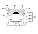
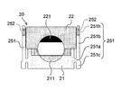
- 5A, 5B, 6A, and 6B are schematic views illustrating the deformation of the tube by the fixing portion.
- the left figure is a front view
- the right figure is a sectional view of the tube T.
- FIG. 5A and FIG. 5B show an example of the fixing portion 20 including the second intermediate member 221.
- the second intermediate member 221 is provided at a contact portion of the second fixing member 22 with the tube T.
- a second flat surface 221a is provided at a contact portion of the second intermediate member 221 with the tube T.
- the light emitting / receiving surface 10a of the sensor module 10 attached to the second fixing member 22 is flush with the second flat surface 221a.
- the flat surface fs2 is formed on the tube T, the flat surface fs2 and the light emitting / receiving surface 10a are in close contact with each other on a flat surface. For example, there is no air layer or bubbles between the flat surface fs2 and the light emitting / receiving surface 10a. Thereby, the optical refractive index change between the tube T and the light emitting / receiving unit 15 can be stabilized, and highly accurate measurement can be performed.
- FIG. 6A and 6B show an example of the fixing portion 20 including the first intermediate member 211 and the second intermediate member 221.
- the first intermediate member 211 is provided at the contact portion of the first fixing member 21 with the tube T.
- a first flat surface 211 a is provided in a contact portion between the first intermediate member 211 and the tube T.
- the tube T and the second intermediate member 221 are in close contact with each other in a plane, and the tube T and the first intermediate member 211 are in close contact with each other in a plane.
- an air layer or bubbles are not interposed between the flat surface fs2 and the second intermediate member 221, and an air layer or bubbles are not interposed between the flat surface fs1 and the first intermediate member 211. .
- the light emitting unit 11 is provided on the second fixing member 22, and the light emitting element 11a is disposed on the second flat surface 221a.
- the light receiving portion 12 is provided on the first fixing member 21, and the light receiving element 12a is disposed on the first flat surface 211a.
- the light emitted from the light emitting element 11a enters the tube T from the flat surface fs2, and the light transmitted through the blood is emitted from the flat surface fs1 and received by the light receiving element 12a.
- highly accurate measurement can be performed in the light transmission type sensor.
- the light emitting unit 11 may be provided on the first fixing member 21 and the light receiving unit 12 may be provided on the second fixing member 22.
- the first intermediate member 211 may be separable from other parts of the first fixing member 21 or may be integrated.
- the second intermediate member 221 may be separable from other parts of the second fixing member 22 or may be integrated. Further, the first intermediate member 211 and the second intermediate member 221 may be formed by deforming the tube T to form a flat surface, or the tube T and the light emitting / receiving unit 15 (light emitting element 11a, light receiving element 12a). And a member that forms a flat surface between them (an optically transparent adhesive sheet is exemplified as such a member).
- FIG. 7 is a schematic cross-sectional view illustrating the collapse of the tube.
- FIG. 7 shows an enlarged view of a part of the portion sandwiching the tube T.
- the crushing amount of the tube T is (( ⁇ 1- ⁇ 2) / ⁇ 1) ⁇ 100%.
- the crushing amount is 10% to 60%, preferably 20% to 55%, more preferably 25% to 40%. can do.
- FIG. 8 is a perspective view showing an example in which a wall is provided in the fixed portion.
- a wall 205 is provided on the side surface at a portion where the tube T is sandwiched.
- the wall 205 is a flat surface and is in close contact with the side surface of the tube T. Thereby, the approach of the disturbance light from the side surface of the tube T can be suppressed effectively.
- the fixed portion 20 is made of a light shielding material, it is possible to more effectively suppress the entry of ambient light from the outside.
- FIG. 9 is a schematic diagram showing an application example of the measuring apparatus according to the present embodiment.
- FIG. 9 shows an example in which the measuring device 1 of this embodiment is applied to the artificial dialysis device 100.
- the artificial dialysis apparatus 100 includes a monitor 120 provided in the housing 110, a blood pump 130, a dialysate management unit 140, and a dialyzer 150.
- a tube T 1 connected to a patient shunt (not shown) is connected to the upstream side of the blood pump 130.
- the tube T2 connected to the downstream side of the blood pump 130 is connected to the blood inlet side of the dialyzer 150.
- a tube T3 is connected to the blood outlet side of the dialyzer 150 and is connected to a patient shunt.
- the tube T4 connected to the dialysate inlet side of the dialyzer 150 is connected to the feed-side coupler 140a of the dialysate management unit 140.
- the tube T5 connected to the dialysate outlet side of the dialyzer 150 is connected to the recovery-side coupler 140b of the dialysate management unit 140.
- the blood of the patient is sent from the tube T1 to the dialyzer 150 through the tube T2 by operating the blood pump 130 in the artificial dialysis apparatus 100.
- the dialyzer 150 is supplied with dialysate from the dialysate management section 140 via the tube T4 and is collected by the dialysate management section 140 via the tube T5.
- the dialyzed blood is returned from the dialyzer 150 to the patient via the tube T3.
- blood is circulated while performing the rotation speed control of the blood pump 130, circulation of the dialysate, drainage control, temperature control, etc., and the patient's blood is dialyzed.
- the measuring device 1 is attached to at least one of tubes T1, T2, and T3 through which blood flows.
- the measuring device 1 is attached to the tube T ⁇ b> 2 on the downstream side of the blood pump 130.
- the measuring apparatus 1 of the present embodiment By attaching the measuring apparatus 1 of the present embodiment to the artificial dialysis apparatus 100, it is possible to acquire information on blood during dialysis in real time.
- the measuring device 1 is securely fixed to the tube T2 and can perform highly accurate measurement. Therefore, it can be effectively used as a support device for diagnosing the state of dialysis. Moreover, since it is only necessary to fix the measuring device 1 to the outside of the tube T, the burden on the patient is small and the labor of the medical staff is also small. In addition, since it can be installed cleanly, the risk of infection is low.
- the measuring device 1 is retrofitted to the tube T2 of the artificial dialysis device 100, but the artificial dialysis device 100 in which the measuring device 1 is previously attached to the tube T may be configured.
- the measuring apparatus 1 that can accurately and continuously measure the state of the blood flowing in the tube T or the state of the substance in the blood.
- the present invention is not limited to these examples.
- the example in which the measurement device 1 is applied to the artificial dialysis device 100 has been shown.
- the measurement device 1 can be widely applied not only to the artificial dialysis device 100 but also to other blood circulation devices.
- the present invention is also applicable to a device that circulates blood through a tube T, such as an oxygenator.
- those in which those skilled in the art appropriately added, deleted, and changed the design of the above-described embodiments, and combinations of the features of each embodiment as appropriate also include the gist of the present invention. As long as they are within the scope of the present invention.
- the measuring device 1 may be attached to the inside of the artificial dialysis device 100, specifically, to the tube T located in the vicinity of the dialysate management unit 140.
- a material that is opaque with respect to the wavelength of light received and emitted by the light emitting and receiving unit 15 is used as the material constituting the first fixing member 21 and the second fixing member 22. That is not required.
- Recovery side coupler 150 ... Dializer 205 ... Wall 210 ... Tube receiving part 211 ... First intermediate member 211a ... First flat surface 221 ... Second intermediate member 221a ... Second flat Surface 222 ... Cover 251 ... Movable piece 251a ... Support part 251b ... Extension part 251c ... Knob part 251h ... Hole 252 ... Claw T T1, T2, T3, T4, T5 ... tube fs1, fs2 ... flat surface .phi.1, .phi.2 ... outer diameter
Landscapes
- Health & Medical Sciences (AREA)
- Physics & Mathematics (AREA)
- Spectroscopy & Molecular Physics (AREA)
- General Health & Medical Sciences (AREA)
- Life Sciences & Earth Sciences (AREA)
- Heart & Thoracic Surgery (AREA)
- General Physics & Mathematics (AREA)
- Biochemistry (AREA)
- Immunology (AREA)
- Analytical Chemistry (AREA)
- Vascular Medicine (AREA)
- Chemical & Material Sciences (AREA)
- Pathology (AREA)
- Biomedical Technology (AREA)
- Veterinary Medicine (AREA)
- Public Health (AREA)
- Animal Behavior & Ethology (AREA)
- Hematology (AREA)
- Anesthesiology (AREA)
- Engineering & Computer Science (AREA)
- Cardiology (AREA)
- External Artificial Organs (AREA)
- Measurement Of The Respiration, Hearing Ability, Form, And Blood Characteristics Of Living Organisms (AREA)
- Measuring Pulse, Heart Rate, Blood Pressure Or Blood Flow (AREA)
Abstract
本発明の一態様は、チューブ内を循環する血液に関連する診断を支援する計測装置であって、発光波長が806ナノメートル(nm)以上855nm以下の第1近赤外光を含む光を血液に照射する第1発光素子を含む発光部と、血液を経由した第1近赤外光を受ける受光部と、発光部および受光部をチューブの外側に取り付けるための固定部と、を備えたことを特徴とする計測装置である。
Description
本発明は、計測装置に関し、特にチューブ内を循環する血液や血液内の物質に関する計測を行う装置および血液循環装置に関する。
特許文献1には、被測定者の脈波や血圧の情報を、常時、取得する生体情報読取装置が開示される。この生体情報読取装置は、生体からの生体信号を取得する生体信号取得部と、生体信号取得部で取得された生体信号である取得生体信号に基づいて、生体情報を推定する演算を行う演算部と、演算部が推定した生体情報である推定生体情報を生体情報読取装置の外部へ出力する生体情報出力部と、を有する。
また、特許文献2には、検出手段の固体差に関係なく、血液回路を体外循環する実血流量を短時間で、かつ精度よく求めることができる血液浄化装置およびその血液流量演算方法が開示されている。この血液浄化装置は、血液回路で体外循環する患者の血液の濃度指標を検出し得る検出手段を備える。
患者や被検者の血液を体外循環させる装置では、チューブ内に血液を通して循環させて体内に戻している。このような装置において、チューブ内を流れる血液の状態を正確に把握することは重要である。また、短時間で血液や血液内の物質に関する様々な情報を連続的に計測できることが望まれる。
本発明は、チューブ内を循環する血液の状態または血液内の物質の状態を正確かつ連続的に計測することができる計測装置および血液循環装置を提供することを目的とする。
上記課題を解決するため、本発明の一態様は、チューブ内を循環する血液の状態または血液内の物質の状態を計測する計測装置であって、発光波長が806ナノメートル(nm)以上855nm以下の第1近赤外光を含む光を血液に照射する第1発光素子を含む発光部と、血液を経由した第1近赤外光を受ける受光部と、発光部および受光部をチューブの外側に取り付けるための固定部と、を備えたことを特徴とする計測装置である。このような構成によれば、波長806nm以上855nm以下の第1近赤外光を含む光によって血液に関連する様々な情報を取得することができる。また、チューブに発光部および受光部が確実に取り付けられることから、チューブに取り付けても精度の高い計測を行うことができる。
計測装置において、発光部は、発光波長が755nm以上765nm以下の第2近赤外光を含む光を血液に照射する第2発光素子を含み、受光部は、第2近赤外光を受光してもよい。波長806nm以上855nm以下の第1近赤外光と、波長755nm以上765nm以下の第2近赤外光とを用いることで、血液に関連する情報の種類を増やすことができる。
計測装置において、固定部は複数の部材からなり、複数の部材によりチューブを挟持するよう構成してもよい。また、複数の部材は、第1固定部材と第2固定部材とを有し、第1固定部材はチューブを受容するチューブ受け部を有していてもよい。これにより、チューブを挟み込むように固定部を取り付けて、発光部および受光部を安定して固定することができる。
計測装置において、発光部と受光部とが一体となった受発光部を有し、第2固定部材は受発光部を有していてもよい。これにより、第2固定部材の受発光部からチューブ内を通る血液に光を照射し、その反射光を検出する反射型のセンサを構成することができる。
計測装置において、第1固定部材は、受発光部で受発光する光の波長に対して不透明であってもよい。これにより、受発光部で受発光する光に対する外乱光の影響を抑制することができる。
計測装置において、第2固定部材は、チューブと受発光部との間で平坦面を構成する中間部材を有していてもよい。この平坦面によって、チューブと受発光部との間の光学的な屈折率変化を安定させることができ、精度の高い計測を行うことができる。
計測装置において、第1固定部材は発光部と受光部との一方を有し、第2固定部材は発光部と受光部との他方を有していてもよい。これにより、第1固定部材と第2固定部材との間で挟持したチューブ内を通る血液に光を透過して計測を行う透過型のセンサを構成することができる。
計測装置において、第1固定部材および第2固定部材は、受光部と発光部とで受発光する光の波長に対して不透明であってもよい。これにより、受光部と発光部とで受発光する光に対する外乱光の影響を抑制することができる。
計測装置において、第1固定部材は、発光部と受光部との一方とチューブとの間で平坦面を構成する第1中間部材を有し、第2固定部材は、チューブと受発光部との間で平坦面を構成する中間部材を有していてもよい。これらの平坦面によって、チューブと発光部との間の光学的な屈折率変化と、チューブと受光部との間の光学的な屈折率変化とを安定させることができ、精度の高い計測を行うことができる。
計測装置において、固定部は、第1固定部材と第2固定部材との間でチューブを所定の圧力で挟持した状態を維持するクリップ機構を有していてもよい。これにより、チューブに確実に発光部および受光部を取り付けておくことができるとともに、チューブ内の血液の流れを阻害せずに済む。
計測装置において、受光部を中心としてチューブの血液の流れ方向の前後に遮光部が設けられていてもよい。この遮光部によって外乱光が受光部に入ることを抑制し、精度の高い計測を行うことができる。
計測装置において、固定部とチューブとの接触圧力を検出する圧力センサをさらに備えていてもよい。この圧力センサによって固定部とチューブとの適度な接触圧力を維持することができる。また、外気温を測定する温度センサをさらに備えていてもよい。この温度センサによって、外気温に対する計測結果の補償を行うことができる。
計測装置において、発光部による発光および受光部による受光のタイミングを制御するとともに、受光部から出力される信号に基づいて血液に関連する情報を推定する処理を行う制御部をさらに備えていてもよい。これにより、血液に関連する情報を推定する装置を血液循環装置内に組み込むことができる。
本発明の一態様は、血液が循環するチューブを有し、このチューブの外側に前述のいずれかの計測装置が取り付けられた血液循環装置である。これにより、血液循環装置におけるチューブの外側からチューブ内を流れる血液に関連する様々な情報を取得することができる。
本発明によれば、チューブ内を流れる血液の状態または血液内の物質の状態を正確かつ連続的に計測することができる計測装置を提供することが可能になる。
以下、本発明の実施形態を図面に基づいて説明する。なお、以下の説明では、同一の部材には同一の符号を付し、一度説明した部材については適宜その説明を省略する。
(計測装置の構成)
図1は、本実施形態に係る計測装置を例示する斜視図である。
(計測装置の構成)
図1は、本実施形態に係る計測装置を例示する斜視図である。
図2は、本実施形態に係る計測装置の分解斜視図である。
図3Aおよび図3Bは、センサモジュールの構成を例示する図である。
図1に示すように、本実施形態に係る計測装置1は、チューブT内を循環する血液または血液内の物質の状態を計測する装置であり、チューブTを間に挟むようにして使用される。
計測装置1は、発光部11および受光部12を含むセンサモジュール10と、センサモジュール10をチューブTに取り付けるための固定部20とを備える。固定部20は複数の部材である第1固定部材21と、第2固定部材22とを有する。第1固定部材21は、チューブTを受容するチューブ受け部210を有している。
第2固定部材22は第1固定部材21の上に重ねるようにして固定される。ここで、第1固定部材21と第2固定部材22との間にはクリップ機構25が設けられていてもよい。クリップ機構25によって、第1固定部材21と第2固定部材22とを重ねた状態で容易に固定および分離することができる。
第2固定部材22にはセンサモジュール10が取り付けられ、発光部11および受光部12の受発光面10aが第1固定部材21側、すなわちチューブT側になるよう配置される。センサモジュール10は第2固定部材22の例えば上側から収納され、カバー222によって押さえられる。カバー222と第2固定部材22との間にはシール(Oリング等)を設けることが好ましい。
図3Aには、第2固定部材22の裏側(第1固定部材21側)を上にした斜視図が示される。受発光面10aには、発光部11の一対の発光素子11aと、受光部12の受光素子12aとが並んで配置されている。発光部11の一対の発光素子11aと、受光部12の受光素子12aとの並び方向(センサ並び方向)は、チューブTの方向(血液の流れ方向)に沿っていると、血液と受発光部15との位置を近づけて計測することができる。なお、センサ並び方向は、チューブTの幅方向に沿っていてもよい。
発光部11は、発光波長が806nm以上855nm以下の第1近赤外光を含む光を発光する第1発光素子11a1を含む。また、発光部11は、発光波長が755nm以上765nm以下、好ましくは758nm以上762nm以下の第2近赤外光を含む光を発光する第2発光素子11a2を含んでいてもよい。第1発光素子11a1および第2発光素子11a2は、発光ダイオード素子やレーザ素子である。なお、本実施形態では発光部11から第1近赤外光および第2近赤外光を放出するよう構成されるが、少なくとも第1近赤外光を放出するよう構成されていればよい。
発光部11から放出される第1近赤外光および第2近赤外光は、チューブTの外側からチューブT内を流れる血液に向けて照射される。
受光部12は、発光部11から放出されチューブT内を流れる血液を経由した第1近赤外光を受けて電気信号に変換する受光素子12aを有する。受光素子12aは、例えばフォトダイオードである。本実施形態では、受光素子12aは第1近赤外光のほか、第2近赤外光も受光して、その受光量に応じた電気信号を出力する感度を有する。
発光部11と受光部12とは一体となって受発光部15を構成している。図3Bには、センサモジュール10の構成を例示するブロック図が示される。センサモジュール10は、発光部11、受光部12、制御部13および入出力インタフェース部14を備える。
発光部11は、第1発光素子11a1および第2発光素子11a2をそれぞれ駆動するドライブ回路11bを有する。また、受光部12は、受光素子12aが出力する受光信号を増幅する増幅回路12bを有する。これらの回路はチップ化されていてもよい。
制御部13は、マイクロコンピュータで構成されている。制御部13は、発光部11のドライブ回路11bにタイミング信号を送信して、第1発光素子11a1および第2発光素子11a2から近赤外光を発するように制御することができる。また、制御部13は、内蔵のアナログ-デジタル変換回路を用いて、受光部12の増幅回路12bから出力された増幅後の受光信号を処理可能なデジタル形式の信号情報に変換し、この変換した信号情報に基づいて、チューブT内を通る血液に関する情報を推定する。
例えば、第1近赤外光を用いた計測では、チューブT内を通る血液のヘマトクリット(Hct)、血流の拍動、血流量、流速などを得ることができる。また、第1近赤外光および第2近赤外光の両方を用いた計測では、血中ヘモグロビン変化(Hb変化量)、血中酸素比率変化(酸素度)などを得ることができる。
ここで、酸素化ヘモグロビンおよび脱酸素化ヘモグロビンの吸光度は波長805nmにおいて等しく、波長805nmよりも長波長では酸素化ヘモグロビンの吸光度が脱酸素化ヘモグロビンの吸光度よりも大きく、波長805nmよりも短波長では酸素化ヘモグロビンの吸光度が脱酸素化ヘモグロビンの吸光度よりも小さくなる。したがって、波長806nm以上855nm以下の第1近赤外光を含む光、好ましくは第1近赤外光の波長域に発光ピークを有する光を用いることで、酸素化ヘモグロビンを優先的に測定することができる。
そして、ヘモグロビンの量からヘマトクリット(Hct)を計測できることになる。本実施形態に係るセンサモジュール10を用いた計測では、ヘマトクリット(Hct)を±1%以下の精度で計測することができる。また、センサモジュール10では10ミリ秒程度のサンプリングレートで計測できるため、血液に関する情報を連続的に得ることができる。
また、波長805nmよりも短波長の光を含む光により測定を行うと、脱酸素化ヘモグロビンを優先的に測定することができる。そのような光として、波長755nm以上765nm以下(好ましくは758nm以上762nm以下)の第2近赤外光を含む光が例示され、第2近赤外光の波長域に発光ピークを有する光が好ましい光として例示される。そして、第1近赤外光を含む光による測定結果および第2近赤外光を含む光による測定結果から、血中酸素比率変化(酸素度)またはこれに関連する情報を導き出すことが可能である。
このような近赤外光を用いた計測を行うため、第1固定部材21や第2固定部材22の少なくとも一方は、受発光部15で受発光する光の波長に対して不透明であることが好ましい。例えば、第1固定部材21や第2固定部材22を黒体や顔料を含む遮光材料(樹脂、金属)で形成したり、表面が遮光塗料で覆われた構成にしたりする。これにより、受発光部15で受発光する光に対する外乱光の影響を抑制して、精度の高い計測を行うことができる。
また、計測装置1においては、受光部12を中心としてチューブTの血液の流れ方向の前後に遮光部が設けられていてもよい。遮光部は、受光部12の前後のそれぞれに数cm以上、30cm以下程度設けられることが好ましい。遮光部は、チューブTの周囲を覆うように構成されていてもよいし、チューブTの外表面に遮光コーティングされていてもよい。この遮光部によって外乱光が受光部12に入ることを抑制し、精度の高い計測を行うことができる。
また、計測装置1は、外気温を測定する温度センサをさらに備えていてもよい。この温度センサによって、外気温に対する計測結果の補償を行い、さらに精度の高い計測を行うことが可能となる。
図4A、図4B、図4Cは、固定部の着脱について例示する模式正面図である。
図4Aには、第1固定部材21の上に第2固定部材22が配置された状態が示される。図4Bには、クリップ機構25で固定される前の状態が示される。図4Cには、クリップ機構25で固定された状態が示される。
クリップ機構25は、第1固定部材21の両側面に設けられた可動片251と、第2固定部材22の両側面に設けられた爪252とを有する。可動片251は、支持部251aを中心として一方に延びる延出部251bと、他方に伸びる摘まみ部251cとを有する。延出部251bには爪252と嵌合可能な孔251hが設けられている。摘まみ部251cを押すことで支持部251aを中心として延出部251bが外側に開くようになっている。摘まみ部251cを押さない状態では延出部251bは閉じるようになる。
図4Aに示すように、第1固定部材21の上に第2固定部材22を重ねた状態で、第2固定部材22を第1固定部材21側に押し込む。これにより、図4Bに示すように爪252によって延出部251bが押し広げられる。さらに押し込んでいくと、図4Cに示すように爪252が延出部251bの孔251hに嵌合して、延出部251bが閉じる状態となる。これによって第1固定部材21と第2固定部材22との固定が完了する。
第1固定部材21と第2固定部材22とを分離するには、摘まみ部251cを押すことで延出部251bを外側に広げる。爪252が延出部251bの孔251hから出た状態で第2固定部材22を引き上げることで、図4Aに示すように第1固定部材21と第2固定部材22とが分離する状態となる。
このようなクリップ機構25によって第1固定部材21と第2固定部材22との固定および分離が容易となる。すなわち、チューブTへの取り付けおよび取り外しを容易に行うことができる。また、クリップ機構25によって第1固定部材21と第2固定部材22との間でチューブTを所定の圧力で挟持した状態を維持することができる。これにより、センサモジュール10をチューブTに確実に取り付けておくことができるとともに、チューブT内の血液の流れを阻害せずに済む。
なお、固定部20とチューブTとの接触圧力を検出する圧力センサ(図示せず)が設けられていてもよい。例えば、固定部20のチューブTとの接触部に圧力センサを設けておく。この圧力センサによって固定部20とチューブTとの接触圧力を検知し、予め設定した範囲内にあるか否かを判定する。これにより、固定部20とチューブTとの接触圧力を適正な範囲に維持することができるとともに、異常な接触圧力を検知した場合には警告を出すことができる。
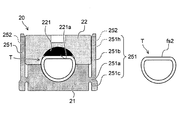
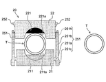
図5A、図5B、図6A、図6Bは、固定部によるチューブの変形について例示する模式図である。
いずれも左図は正面図であり、右図はチューブTの断面図である。
図5Aおよび図5Bには、第2中間部材221を備えた固定部20の例が示される。第2中間部材221は、第2固定部材22のチューブTとの接触部分に設けられる。第2中間部材221のチューブTとの接触部分には第2平坦面221aが設けられる。第2固定部材22に取り付けられたセンサモジュール10の受発光面10aが第2平坦面221aと同一平面になっている。
図5Aに示すように、第1固定部材21と第2固定部材22とでチューブTを挟み、図5Bに示すように第1固定部材21と第2固定部材22とを固定すると、チューブTが挟持される状態になる。この際、第2中間部材221の第2平坦面221aがチューブTと接触してチューブTが僅かに潰され、チューブTの上側に平坦面fs2が構成される。
チューブTに平坦面fs2が構成されることで、平坦面fs2と受発光面10aとが平面で密着する。例えば、平坦面fs2と受発光面10aとの間に空気の層や気泡が介在しない状態となる。これにより、チューブTと受発光部15との間の光学的な屈折率変化を安定させることができ、精度の高い計測を行うことができる。
図6Aおよび図6Bには、第1中間部材211および第2中間部材221を備えた固定部20の例が示される。第1中間部材211は第1固定部材21のチューブTとの接触部分に設けられる。第1中間部材211のチューブTとの接触部分には第1平坦面211aが設けられる。
図6Aに示すように、第1固定部材21と第2固定部材22とでチューブTを挟み、図6Bに示すように第1固定部材21と第2固定部材22とを固定すると、チューブTが挟持される状態になる。この際、第1中間部材211の第1平坦面211aおよび第2中間部材221の第2平坦面221aがチューブTと接触してチューブTが僅かに潰され、チューブTの上下に平坦面fs2および平坦面fs1が構成される。
チューブTの上下に平坦面fs2および平坦面fs1が構成されることで、チューブTと第2中間部材221とが平面で密着し、チューブTと第1中間部材211との間が平面で密着する。例えば、平坦面fs2と第2中間部材221との間に空気の層や気泡が介在しない状態となり、平坦面fs1と第1中間部材211との間に空気の層や気泡が介在しない状態となる。
これにより、チューブTを通る血液に対して第1近赤外光や第2近赤外光を透過させる構成の場合、平坦面fs1および平坦面fs2によってチューブTと発光素子11aとの間や、チューブTと受光素子12aとの間の光学的な屈折率変化を安定させることができ、精度の高い計測を行うことができる。
例えば、第2固定部材22に発光部11を設け、第2平坦面221aに発光素子11aを配置する。また、第1固定部材21に受光部12を設け、第1平坦面211aに受光素子12aを配置する。これにより、発光素子11aから放出された光を平坦面fs2からチューブT内に入射し、血液を透過した光を平坦面fs1から出射させて受光素子12aで受光させる。これにより光透過型のセンサにおいて精度の高い計測を行うことができる。なお、第1固定部材21に発光部11を設け、第2固定部材22に受光部12を設けてもよい。
なお、第1中間部材211は第1固定部材21の他の部分と分離可能であってもよいし、一体であってもよい。また、第2中間部材221は第2固定部材22の他の部分と分離可能であってもよいし、一体であってもよい。さらに、第1中間部材211および第2中間部材221は、チューブTを変形させて平坦面を形成するものであってもよいし、チューブTと受発光部15(発光素子11a、受光素子12a)との間に充填されて平坦面を形成する部材(そのような部材として、光学透明粘着シートが例示される。)を含んでいてもよい。
図7は、チューブの潰れについて例示する模式断面図である。
図7には、チューブTを挟持する部分の一部の拡大図が示される。
第1固定部材21と第2固定部材22との間でチューブTを挟持する場合、発光素子11aや受光素子12aとの密着性向上とともに、血液の流れを阻害しないような圧力で挟持する必要がある。
図7に示すように、チューブTの外径をφ1、固定部20での挟持によって潰れた状態のチューブTの外径をφ2とした場合、チューブTの潰し量は、((φ1-φ2)/φ1)×100%で表される。チューブTの外径φ1を12mmとして潰し量と応力との関係をシミュレーションした結果、潰し量は10%以上60%以下、好ましくは20%以上55%以下、さらに好ましくは25%以上40%以下とすることができる。この範囲の潰し量にすることで、発光素子11aおよび受光素子12aとの十分な密着力を得るとともに、血液の流れを阻害しないことになる。
また、第1固定部材21および第2固定部材22の端部がチューブTと接触する場合、端部がチューブTに食い込まないようにR面取りを施していくことが好ましい。
図8は、固定部に壁を設けた例を示す斜視図である。
この固定部20では、チューブTを挟持する部分において側面に壁205が設けられている。壁205は平坦な面になっており、チューブTの側面に密着することになる。これにより、チューブTの側面からの外乱光の進入を効果的に抑制することができる。特に、固定部20が遮光性の材料で構成されている場合には、外部からの外乱光の進入をより効果的に抑制することができる。
図9は、本実施形態に係る計測装置の適用例を示す模式図である。
図9には、人工透析装置100に本実施形態の計測装置1を適用した例が示される。
人工透析装置100は、筐体110に設けられたモニタ120と、血液ポンプ130と、透析液管理部140と、ダイアライザ150とを備える。患者のシャント(図示せず)と接続されたチューブT1は、血液ポンプ130の上流側に接続される。血液ポンプ130の下流側に接続されたチューブT2はダイアライザ150の血液入口側に接続される。ダイアライザ150の血液出口側にはチューブT3が接続され、患者のシャントに接続される。
ダイアライザ150の透析液入口側に接続されたチューブT4は、透析液管理部140の送り側カプラ140aに接続される。ダイアライザ150の透析液出口側に接続されたチューブT5は、透析液管理部140の回収側カプラ140bに接続される。
人工透析装置100において血液ポンプ130を作動させることで患者の血液がチューブT1からチューブT2を介してダイアライザ150に送られる。ダイアライザ150には透析液管理部140からチューブT4を介して透析液が供給され、チューブT5を介して透析液管理部140に回収される。透析後の血液は、ダイアライザ150からチューブT3を介して患者に戻される。人工透析装置100では、血液ポンプ130の回転速度制御、透析液の循環、排液制御、温度制御などを行いながら血液を循環させて、患者の血液の透析を行っていく。
本実施形態に係る計測装置1は、血液が流れるチューブT1、T2およびT3の少なくともいずれかに取り付けられる。図9に示す例では、血液ポンプ130の下流側のチューブT2に計測装置1が取り付けられている。
人工透析装置100に本実施形態の計測装置1を取り付けることで、透析中の血液に関する情報をリアルタイムで取得することができる。計測装置1はチューブT2に確実に固定され、精度の高い計測を行うことができる。したがって、透析の状態を診断するための支援装置として有効に活用することができる。また、チューブTの外側に計測装置1を固定するだけでよいため、患者への負担が少なく、医療従事者の作業の手間も少ない。また、清潔に後付けできるため、感染リスクも少ない。
図示する例では人工透析装置100のチューブT2に計測装置1を後付けしているが、予めチューブTに計測装置1が取り付けられた人工透析装置100を構成してもよい。
以上説明したように、実施形態によれば、チューブT内を流れる血液の状態または血液内の物質の状態を正確かつ連続的に計測することができる計測装置1を提供することが可能になる。
なお、上記に本実施形態を説明したが、本発明はこれらの例に限定されるものではない。例えば、上記実施形態では、人工透析装置100に計測装置1を適用する例を示したが、計測装置1は人工透析装置100のみならず、その他の血液循環装置に広く適用可能であり、例えば、人工心肺装置など血液をチューブTによって循環させる装置にも適用可能である。また、前述の各実施形態に対して、当業者が適宜、構成要素の追加、削除、設計変更を行ったものや、各実施形態の特徴を適宜組み合わせたものも、本発明の要旨を備えている限り、本発明の範囲に包含される。例えば、計測装置1は、人工透析装置100の内部、具体例を挙げれば透析液管理部140の近傍に位置するチューブT、に取り付けられていてもよい。この場合には、外乱光の影響が生じにくいため、第1固定部材21および第2固定部材22を構成する材料として、受発光部15で受発光する光の波長に対して不透明な材料を用いることは必要とされない。
本特許出願は2016年10月19日に出願した日本国特許出願第2016-205582号に基づきその優先権を主張するものであり、日本国特許出願第2016-205582号の全内容を本願に援用する。
1…計測装置
10…センサモジュール
10a…受発光面
11…発光部
11a…発光素子
11a1…第1発光素子
11a2…第2発光素子
11b…ドライブ回路
12…受光部
12a…受光素子
12b…増幅回路
13…制御部
14…入出力インタフェース部
15…受発光部
20…固定部
21…第1固定部材
22…第2固定部材
25…クリップ機構
100…人工透析装置
110…筐体
120…モニタ
130…血液ポンプ
140…透析液管理部
140a…送り側カプラ
140b…回収側カプラ
150…ダイアライザ
205…壁
210…チューブ受け部
211…第1中間部材
211a…第1平坦面
221…第2中間部材
221a…第2平坦面
222…カバー
251…可動片
251a…支持部
251b…延出部
251c…摘み部
251h…孔
252…爪
T,T1,T2,T3,T4、T5…チューブ
fs1,fs2…平坦面
φ1,φ2…外径
10…センサモジュール
10a…受発光面
11…発光部
11a…発光素子
11a1…第1発光素子
11a2…第2発光素子
11b…ドライブ回路
12…受光部
12a…受光素子
12b…増幅回路
13…制御部
14…入出力インタフェース部
15…受発光部
20…固定部
21…第1固定部材
22…第2固定部材
25…クリップ機構
100…人工透析装置
110…筐体
120…モニタ
130…血液ポンプ
140…透析液管理部
140a…送り側カプラ
140b…回収側カプラ
150…ダイアライザ
205…壁
210…チューブ受け部
211…第1中間部材
211a…第1平坦面
221…第2中間部材
221a…第2平坦面
222…カバー
251…可動片
251a…支持部
251b…延出部
251c…摘み部
251h…孔
252…爪
T,T1,T2,T3,T4、T5…チューブ
fs1,fs2…平坦面
φ1,φ2…外径
Claims (16)
- チューブ内を循環する血液の状態または前記血液内の物質の状態を計測する計測装置であって、
発光波長が806ナノメートル(nm)以上855nm以下の第1近赤外光を含む光を前記血液に照射する第1発光素子を含む発光部と、
前記血液を経由した前記第1近赤外光を受ける受光部と、
前記発光部および前記受光部を前記チューブの外側に取り付けるための固定部と、
を備えたことを特徴とする計測装置。 - 前記発光部は、発光波長が755nm以上765nm以下の第2近赤外光を含む光を前記血液に照射する第2発光素子を含み、
前記受光部は、前記第2近赤外光を受光する、請求項1記載の計測装置。 - 前記固定部は複数の部材からなり、前記複数の部材により前記チューブを挟持する、請求項1または2に記載の計測装置。
- 前記複数の部材は、第1固定部材と第2固定部材とを有し、
前記第1固定部材は前記チューブを受容するチューブ受け部を有する、請求項3に記載の計測装置。 - 前記発光部と前記受光部とが一体となった受発光部を有し、
前記第2固定部材は前記受発光部を有する、請求項4に記載の計測装置。 - 前記第1固定部材は、前記受発光部で受発光する光の波長に対して不透明である、請求項5記載の計測装置。
- 前記第2固定部材は、前記チューブと前記受発光部との間で平坦面を構成する中間部材を有する、請求項5または6に記載の計測装置。
- 前記第1固定部材は前記発光部と前記受光部との一方を有し、
前記第2固定部材は前記発光部と前記受光部との他方を有する、請求項4に記載の計測装置。 - 前記第1固定部材および前記第2固定部材は、前記受光部と前記発光部とで受発光する光の波長に対して不透明である、請求項8に記載の計測装置。
- 前記第1固定部材は、前記発光部と前記受光部との一方と前記チューブとの間で平坦面を構成する第1中間部材を有し、前記第2固定部材は、前記発光部と前記受光部との他方と前記チューブとの間で平坦面を構成する第2中間部材を有する、請求項8または9に記載の計測装置。
- 前記固定部は、前記第1固定部材と前記第2固定部材との間で前記チューブを所定の圧力で挟持した状態を維持するクリップ機構を有する、請求項4~10のいずれか1つに記載の計測装置。
- 前記受光部を中心として前記チューブの前記血液の流れ方向の前後に遮光部が設けられた、請求項1~11のいずれか1つに記載の計測装置。
- 前記固定部と前記チューブとの接触圧力を検出する圧力センサをさらに備えた、請求項1~12のいずれか1つに記載の計測装置。
- 外気温を測定する温度センサをさらに備えた、請求項1~13のいずれか1つに記載の計測装置。
- 前記発光部による発光および前記受光部による受光のタイミングを制御するとともに、前記受光部から出力される信号に基づいて前記血液に関連する情報を推定する処理を行う制御部をさらに備えた、請求項1~14のいずれか1つに記載の計測装置。
- 血液が循環するチューブを有し、
前記チューブの外側に請求項1~15のいずれか1つに記載の計測装置が取り付けられた、血液循環装置。
Applications Claiming Priority (2)
| Application Number | Priority Date | Filing Date | Title |
|---|---|---|---|
| JP2016-205582 | 2016-10-19 | ||
| JP2016205582A JP2019213570A (ja) | 2016-10-19 | 2016-10-19 | 計測装置および血液循環装置 |
Publications (1)
| Publication Number | Publication Date |
|---|---|
| WO2018074299A1 true WO2018074299A1 (ja) | 2018-04-26 |
Family
ID=62018477
Family Applications (1)
| Application Number | Title | Priority Date | Filing Date |
|---|---|---|---|
| PCT/JP2017/036806 Ceased WO2018074299A1 (ja) | 2016-10-19 | 2017-10-11 | 計測装置および血液循環装置 |
Country Status (2)
| Country | Link |
|---|---|
| JP (1) | JP2019213570A (ja) |
| WO (1) | WO2018074299A1 (ja) |
Families Citing this family (3)
| Publication number | Priority date | Publication date | Assignee | Title |
|---|---|---|---|---|
| WO2021053201A1 (en) | 2019-09-19 | 2021-03-25 | Gambro Lundia Ab | Non-invasive sensor for determining a heartbeat and/or heart rate in a segment of an extracorporeal blood circuit |
| WO2021210111A1 (ja) * | 2020-04-15 | 2021-10-21 | セルスペクト株式会社 | 測定方法、測定装置、測定プログラム、判定装置、判定装置の作動方法、及び判定プログラム |
| JP7625941B2 (ja) * | 2021-04-01 | 2025-02-04 | 東レ株式会社 | ヘマトクリットセンサ |
Citations (6)
| Publication number | Priority date | Publication date | Assignee | Title |
|---|---|---|---|---|
| US5601080A (en) * | 1994-12-28 | 1997-02-11 | Coretech Medical Technologies Corporation | Spectrophotometric blood analysis |
| JP2002529174A (ja) * | 1998-11-06 | 2002-09-10 | メドトロニック・アヴェコア・カーディオヴァスキュラー・インコーポレーテッド | 血液パラメータを測定する装置及び方法 |
| JP2008148820A (ja) * | 2006-12-15 | 2008-07-03 | Chunichi Denshi Co Ltd | 酸素飽和度測定装置 |
| WO2010136962A1 (en) * | 2009-05-26 | 2010-12-02 | Datamed Srl | Apparatus and method for spectrophotometric measurements of blood parameters |
| JP2012040058A (ja) * | 2010-08-13 | 2012-03-01 | Asahi Kasei Kuraray Medical Co Ltd | 血液成分濃度測定装置及び血液成分濃度測定方法 |
| JP2016002167A (ja) * | 2014-06-16 | 2016-01-12 | ジーニアルライト株式会社 | 手首装着型パルスオキシメータ |
-
2016
- 2016-10-19 JP JP2016205582A patent/JP2019213570A/ja active Pending
-
2017
- 2017-10-11 WO PCT/JP2017/036806 patent/WO2018074299A1/ja not_active Ceased
Patent Citations (6)
| Publication number | Priority date | Publication date | Assignee | Title |
|---|---|---|---|---|
| US5601080A (en) * | 1994-12-28 | 1997-02-11 | Coretech Medical Technologies Corporation | Spectrophotometric blood analysis |
| JP2002529174A (ja) * | 1998-11-06 | 2002-09-10 | メドトロニック・アヴェコア・カーディオヴァスキュラー・インコーポレーテッド | 血液パラメータを測定する装置及び方法 |
| JP2008148820A (ja) * | 2006-12-15 | 2008-07-03 | Chunichi Denshi Co Ltd | 酸素飽和度測定装置 |
| WO2010136962A1 (en) * | 2009-05-26 | 2010-12-02 | Datamed Srl | Apparatus and method for spectrophotometric measurements of blood parameters |
| JP2012040058A (ja) * | 2010-08-13 | 2012-03-01 | Asahi Kasei Kuraray Medical Co Ltd | 血液成分濃度測定装置及び血液成分濃度測定方法 |
| JP2016002167A (ja) * | 2014-06-16 | 2016-01-12 | ジーニアルライト株式会社 | 手首装着型パルスオキシメータ |
Also Published As
| Publication number | Publication date |
|---|---|
| JP2019213570A (ja) | 2019-12-19 |
Similar Documents
| Publication | Publication Date | Title |
|---|---|---|
| US10583239B2 (en) | Fluid flow rate measuring and gas bubble detecting apparatus | |
| EP2613699B1 (en) | Blood chamber for an optical blood monitoring system | |
| US8830449B1 (en) | Blood analysis system | |
| US8517968B2 (en) | Shrouded sensor clip assembly and blood chamber for an optical blood monitoring system | |
| US8777891B2 (en) | Apparatus and methods for early stage peritonitis detection and for in vivo testing of bodily fluid | |
| JP2807650B2 (ja) | 組織の特性決定のための装置 | |
| EP1529544B1 (en) | Hematocrit sensor | |
| CN107307871A (zh) | 用于光学监视系统的传感器夹组件 | |
| JP2018531366A6 (ja) | 直接光の示差測定システム | |
| JP2018531366A (ja) | 直接光の示差測定システム | |
| JP2002529174A (ja) | 血液パラメータを測定する装置及び方法 | |
| US8328748B2 (en) | Off-axis blood chamber | |
| WO2018074299A1 (ja) | 計測装置および血液循環装置 | |
| WO2015127182A1 (en) | Self calibrating blood chamber | |
| EP2434952B1 (en) | Apparatus and method for spectrophotometric measurements of blood parameters | |
| JP7241033B2 (ja) | 成分測定システム及び測定装置 | |
| US20080076993A1 (en) | Medical sensor and technique for using the same | |
| JP4393568B2 (ja) | 脈波測定器 | |
| JP6067620B2 (ja) | 血液浄化装置 | |
| WO2008136548A1 (en) | Device of measuring and monitoring a hemoglobin value through blood tube | |
| CN101184438A (zh) | 生物体信息计测传感器 | |
| JP2013048834A (ja) | 成分分析装置 | |
| EP3111842B1 (en) | An apparatus comprising a light detector, a light source and optics | |
| KR20220168659A (ko) | 귀 착용형 산소포화도 측정 센서 프로브 | |
| JP2013195223A (ja) | 測定装置および測定装置セット |
Legal Events
| Date | Code | Title | Description |
|---|---|---|---|
| 121 | Ep: the epo has been informed by wipo that ep was designated in this application |
Ref document number: 17862229 Country of ref document: EP Kind code of ref document: A1 |
|
| NENP | Non-entry into the national phase |
Ref country code: DE |
|
| 122 | Ep: pct application non-entry in european phase |
Ref document number: 17862229 Country of ref document: EP Kind code of ref document: A1 |
|
| NENP | Non-entry into the national phase |
Ref country code: JP |