WO2018074284A1 - Tire - Google Patents
Tire Download PDFInfo
- Publication number
- WO2018074284A1 WO2018074284A1 PCT/JP2017/036664 JP2017036664W WO2018074284A1 WO 2018074284 A1 WO2018074284 A1 WO 2018074284A1 JP 2017036664 W JP2017036664 W JP 2017036664W WO 2018074284 A1 WO2018074284 A1 WO 2018074284A1
- Authority
- WO
- WIPO (PCT)
- Prior art keywords
- tire
- annular
- resin
- belt layer
- cord
- Prior art date
Links
Images


Classifications
-
- B—PERFORMING OPERATIONS; TRANSPORTING
- B60—VEHICLES IN GENERAL
- B60C—VEHICLE TYRES; TYRE INFLATION; TYRE CHANGING; CONNECTING VALVES TO INFLATABLE ELASTIC BODIES IN GENERAL; DEVICES OR ARRANGEMENTS RELATED TO TYRES
- B60C9/00—Reinforcements or ply arrangement of pneumatic tyres
- B60C9/18—Structure or arrangement of belts or breakers, crown-reinforcing or cushioning layers
- B60C9/20—Structure or arrangement of belts or breakers, crown-reinforcing or cushioning layers built-up from rubberised plies each having all cords arranged substantially parallel
- B60C9/22—Structure or arrangement of belts or breakers, crown-reinforcing or cushioning layers built-up from rubberised plies each having all cords arranged substantially parallel the plies being arranged with all cords disposed along the circumference of the tyre
-
- B—PERFORMING OPERATIONS; TRANSPORTING
- B60—VEHICLES IN GENERAL
- B60C—VEHICLE TYRES; TYRE INFLATION; TYRE CHANGING; CONNECTING VALVES TO INFLATABLE ELASTIC BODIES IN GENERAL; DEVICES OR ARRANGEMENTS RELATED TO TYRES
- B60C5/00—Inflatable pneumatic tyres or inner tubes
- B60C5/01—Inflatable pneumatic tyres or inner tubes without substantial cord reinforcement, e.g. cordless tyres, cast tyres
-
- B—PERFORMING OPERATIONS; TRANSPORTING
- B60—VEHICLES IN GENERAL
- B60C—VEHICLE TYRES; TYRE INFLATION; TYRE CHANGING; CONNECTING VALVES TO INFLATABLE ELASTIC BODIES IN GENERAL; DEVICES OR ARRANGEMENTS RELATED TO TYRES
- B60C9/00—Reinforcements or ply arrangement of pneumatic tyres
- B60C9/18—Structure or arrangement of belts or breakers, crown-reinforcing or cushioning layers
- B60C9/20—Structure or arrangement of belts or breakers, crown-reinforcing or cushioning layers built-up from rubberised plies each having all cords arranged substantially parallel
- B60C9/22—Structure or arrangement of belts or breakers, crown-reinforcing or cushioning layers built-up from rubberised plies each having all cords arranged substantially parallel the plies being arranged with all cords disposed along the circumference of the tyre
- B60C9/2204—Structure or arrangement of belts or breakers, crown-reinforcing or cushioning layers built-up from rubberised plies each having all cords arranged substantially parallel the plies being arranged with all cords disposed along the circumference of the tyre obtained by circumferentially narrow strip winding
-
- B—PERFORMING OPERATIONS; TRANSPORTING
- B29—WORKING OF PLASTICS; WORKING OF SUBSTANCES IN A PLASTIC STATE IN GENERAL
- B29D—PRODUCING PARTICULAR ARTICLES FROM PLASTICS OR FROM SUBSTANCES IN A PLASTIC STATE
- B29D30/00—Producing pneumatic or solid tyres or parts thereof
- B29D30/06—Pneumatic tyres or parts thereof (e.g. produced by casting, moulding, compression moulding, injection moulding, centrifugal casting)
- B29D30/08—Building tyres
- B29D2030/086—Building the tyre carcass by combining two or more sub-assemblies, e.g. two half-carcasses
-
- B—PERFORMING OPERATIONS; TRANSPORTING
- B29—WORKING OF PLASTICS; WORKING OF SUBSTANCES IN A PLASTIC STATE IN GENERAL
- B29D—PRODUCING PARTICULAR ARTICLES FROM PLASTICS OR FROM SUBSTANCES IN A PLASTIC STATE
- B29D30/00—Producing pneumatic or solid tyres or parts thereof
- B29D30/06—Pneumatic tyres or parts thereof (e.g. produced by casting, moulding, compression moulding, injection moulding, centrifugal casting)
- B29D30/38—Textile inserts, e.g. cord or canvas layers, for tyres; Treatment of inserts prior to building the tyre
- B29D30/42—Endless textile bands without bead-rings
- B29D2030/421—General aspects of the joining methods and devices for creating the bands
-
- B—PERFORMING OPERATIONS; TRANSPORTING
- B29—WORKING OF PLASTICS; WORKING OF SUBSTANCES IN A PLASTIC STATE IN GENERAL
- B29D—PRODUCING PARTICULAR ARTICLES FROM PLASTICS OR FROM SUBSTANCES IN A PLASTIC STATE
- B29D30/00—Producing pneumatic or solid tyres or parts thereof
- B29D30/06—Pneumatic tyres or parts thereof (e.g. produced by casting, moulding, compression moulding, injection moulding, centrifugal casting)
- B29D30/70—Annular breakers
- B29D2030/705—Annular breakers the breakers being obtained by cutting a continuous reinforced strip into predefined lengths and placing the cut strips side by side on a suitable support, e.g. a toroidal core or a carcass
-
- B—PERFORMING OPERATIONS; TRANSPORTING
- B60—VEHICLES IN GENERAL
- B60C—VEHICLE TYRES; TYRE INFLATION; TYRE CHANGING; CONNECTING VALVES TO INFLATABLE ELASTIC BODIES IN GENERAL; DEVICES OR ARRANGEMENTS RELATED TO TYRES
- B60C1/00—Tyres characterised by the chemical composition or the physical arrangement or mixture of the composition
- B60C2001/0066—Compositions of the belt layers
Definitions
- the present invention relates to a tire.
- This belt layer is usually formed by winding a belt-like rubber strip formed by covering a reinforcing cord with rubber in a spiral manner around a tire case (for example, Japanese Patent Application Laid-Open No. 2008-168807). reference).
- the rubber strip is slightly inclined with respect to the tire circumferential direction. Price tears may occur.
- the present invention has been made in consideration of the above facts, and an object of the present invention is to provide a tire in which the price tear is reduced and the weight balance is improved.
- the tire according to the first aspect of the present invention includes a tire skeleton member including a bead portion, a side portion continuous to the tire radial direction outer side of the bead portion, and a crown portion continuous to the tire width direction inner side of the side portion,
- An annular annular reinforcement body in which an annular reinforcement cord is coated with a resin has a belt layer arranged in plural along the tire axial direction on the outer side in the tire radial direction of the tire frame member.
- the belt layer is formed by arranging a plurality of annular reinforcing bodies along the tire axial direction on the outer side in the tire radial direction of the tire frame member. Since the annular reinforcing body is annular and endless, the one end and the other end do not overlap in the circumferential direction. Therefore, the weight balance of the tire can be improved. Further, since the annular reinforcing body is not spirally wound and is not inclined with respect to the tire circumferential direction, the price tear can be reduced.
- the reinforcing cord is formed in an annular shape with both ends connected by a connecting member.
- the reinforcing cord can be easily formed in an annular shape by connecting both ends with connecting members.
- the annular reinforcing body is formed by coating a plurality of the reinforcing cords arranged in the tire axial direction with a resin.
- the width of the annular reinforcing cord in the tire axial direction can be widened, and the annular reinforcement necessary for forming the belt layer The number of cords can be reduced to facilitate the manufacture of the tire.
- the tire according to the fourth aspect of the present invention is characterized in that the tire frame member is made of resin.
- the cord tends to tilt when the resin-coated cord is wound spirally.
- inclination can be suppressed.
- the present invention can improve the weight balance of the tire and reduce the price tear.
- FIG. 2B is a cross-sectional view of the annular reinforcing member constituting the belt layer according to the present embodiment, taken along line BB in FIG. 2A.
- FIG. FIG. 2B is a cross-sectional view taken along the line CC of FIG. 2A of the annular reinforcing body constituting the belt layer according to the present embodiment. It is the top view which fractured partially the belt layer concerning this embodiment. It is a side view of the reinforcement cord which constitutes the belt layer concerning this embodiment.
- FIG. 9B is a cross-sectional view taken along the line DD of FIG. 9A of the annular reinforcing body that constitutes the belt layer according to a modification of the present embodiment.
- the tire circumferential direction is indicated by an arrow S
- the tire axial direction (which may be read as the tire width direction)
- the tire radial direction is indicated by an arrow R.
- the tire axial direction means a direction parallel to the tire rotation axis.
- the side far from the tire equatorial plane CL along the tire axial direction will be described as “the tire axial direction outside”, and the side close to the tire equatorial plane CL along the tire axial direction will be described as “the tire axial direction inside”.
- a side far from the tire axis along the tire radial direction is referred to as “tire radial outside”, and a side near the tire axis along the tire radial direction is referred to as “tire radial inner”.
- the tire 10 includes a tire case 17 that is an example of an annular tire frame member, and a belt layer 12.
- the tire case 17 is made of a resin material and is formed in an annular shape in the tire circumferential direction.
- the tire case 17 includes a pair of bead portions 14 arranged at intervals in the tire axial direction, a pair of side portions 16 extending from the pair of bead portions 14 outward in the tire radial direction, and a pair of And a crown portion 18 that connects the side portions 16.
- the bead part 14 is a part which contacts a rim (not shown), and a coating layer 22 described later is provided on the surface.
- the side portion 16 forms a side portion of the tire 10 and is gently curved so as to protrude outward in the tire axial direction from the bead portion 14 toward the crown portion 18.
- the crown portion 18 is a portion that connects the tire radial direction outer end of one side portion 16 and the tire radial direction outer end of the other side portion 16 and supports the tread 30 disposed on the outer side in the tire radial direction. .
- the crown portion 18 has a substantially constant thickness.
- the outer peripheral surface 18A may be formed in a flat shape in the cross section in the tire axial direction, or may have a curved shape bulging outward in the tire radial direction. Note that the outer peripheral surface 18A of the crown portion 18 of the present embodiment is the outer periphery of the tire case 17 on which the belt layer 12 is provided.
- the tire case 17 forms a pair of annular tire halves 17H having one bead portion 14, one side portion 16, and a half-width crown portion 18, and these tire halves 17H face each other.
- the ends of the half-width crown portions 18 are joined to each other at the tire equatorial plane CL.
- the ends are joined using, for example, a resin material for welding 17A.
- the bead core 20 includes a bead cord (not shown).
- the bead cord is composed of a metal cord such as a steel cord, an organic fiber cord, a resin-coated organic fiber cord, or a hard resin.
- the bead core 20 itself may be omitted if the rigidity of the bead portion 14 can be sufficiently secured.
- a coating layer 22 is formed on the surface of the bead portion 14 at least at a contact portion with a rim (not shown) to enhance airtightness with the rim.
- the covering layer 22 is made of a material such as a rubber material that is softer and weather resistant than the tire case 17.
- the coating layer 22 of the present embodiment is folded from the inner surface in the tire axial direction of the bead portion 14 to the outer side in the tire axial direction, and passes through the outer surface of the side portion 16 to the end on the outer side in the tire axial direction of the belt layer 12. It extends to the vicinity of the part. And the extended end part of the coating layer 22 is covered with the tread 30 mentioned later.
- the covering layer 22 may be omitted if the sealing property (airtightness) with the rim (not shown) can be ensured only by the bead portion 14 of the tire case 17.
- the tire case 17 may be an integrally molded product, or the tire case 17 may be manufactured by dividing it into three or more resin members, and these may be joined.
- the tire case 17 may be manufactured separately for each part (for example, the bead part 14, the side part 16, and the crown part 18), and these may be joined and formed.
- each part (for example, bead part 14, side part 16, crown part 18) of tire case 17 may be formed with a resin material which has a different characteristic.
- a reinforcing material (polymer material, metal fiber, cord, nonwoven fabric, woven fabric, etc.) may be embedded in the tire case 17.
- the belt layer 12 is provided on the outer side in the tire radial direction of the tire case 17.
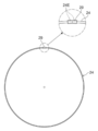
- the belt layer 12 is formed by arranging a plurality of annular reinforcing bodies 28 to be described later on the outer periphery of the tire case 17 (the outer peripheral surface 18A of the crown portion 18) along the tire axial direction.
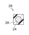
- the annular reinforcing member 28 is formed in an annular shape by covering an annular reinforcing cord 24 with a resin 26.
- the annular reinforcing body 28 has a square cross section.
- the annular reinforcing body 28 has a single reinforcing cord 24 embedded in the resin 26.
- the plurality of annular reinforcing bodies 28 are arranged along the tire circumferential direction on the outer circumferential surface 18A of the crown portion 18 without being inclined with respect to the tire circumferential direction. Adjacent annular reinforcing bodies 28 are welded with resins 26. The resin 26 on the inner peripheral surface of the annular reinforcement 28 is welded to the outer peripheral surface 18A of the crown portion 18.
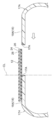
- the reinforcing cord 24 is composed of a monofilament (single wire) such as a metal fiber or an organic fiber, or a multifilament (twisted wire) obtained by twisting these fibers.
- both ends 24 ⁇ / b> E of the reinforcing cord 24 are connected by a connecting member 29, so that the reinforcing cord 24 is formed in an annular shape.
- the connecting member 29 has a cylindrical shape, and is crimped from the outside with one end and the other end of the reinforcing cord 24 inserted into the cylinder.
- the connection member 29 can be formed of metal.
- the positions of the connecting members 29 in the tire circumferential direction of the respective annular reinforcing bodies 28 forming the belt layer 12 are arranged so as not to overlap each other.
- the reinforcing cord 24 may be formed in an annular shape by joining both ends by welding, or in the case of a stranded wire, it may be formed by shifting the end of each filament and twisting in an annular shape. Good.
- the filament may be subjected to an adhesion surface treatment for improving the adhesion with the resin 26.
- an adhesion surface treatment for improving the adhesion with the resin 26.
- This is a metal surface treatment applied to improve adhesion to a thermoplastic material.
- As the surface treatment for adhesion organic plating treatment, immersion surface treatment, or the like can be used.
- organic electrolytic plating treatment disclosed in Japanese Patent Publication No. 5-51671, Japanese Patent Application Laid-Open No. 2001-1445, and the like can be used.
- the immersion surface treatment a surface treatment disclosed in Japanese Patent Application Laid-Open No. 2003-170531 can be used.
- the bead core 20 and the reinforcing cord 24 are immersed in a water-soluble amine compound (or ammonia) aqueous solution for a predetermined time.
- a water-soluble amine compound or ammonia
- the water-soluble amine compound hydrazine and its dielectric
- lower amine compound pyridine, aniline, etc.
- the lower amine methylamine, dimethylamine, trimethylamine, ethylamine, diethylamine, triethylamine are used. Etc. can be used suitably.
- a tread 30 made of a rubber material is disposed outside the belt layer 12 in the tire radial direction.
- the tread 30 covers the belt layer 12 and the tire case 17 from the outer side in the tire radial direction.
- the tread 30 is made of a rubber material that contacts the road surface and has excellent wear resistance.
- the tread 30 may include a cushion rubber whose elastic modulus is set lower than that of the rubber material on the outer side in the tire radial direction on the inner side in the tire radial direction.
- thermoplastic elastomer As the resin material used for the resin 26 that covers the tire case 17 and the reinforcing cord 24 of the present embodiment, a thermoplastic elastomer can be used. In addition to thermoplastic elastomers, engineering plastics (including super engineering plastics) can be used in addition to thermoplastic resins, thermosetting resins, and other general-purpose resins. The resin material here does not include vulcanized rubber.
- Thermoplastic resin refers to a polymer compound that softens and flows as the temperature rises and becomes relatively hard and strong when cooled.
- the material softens and flows with increasing temperature, and becomes relatively hard and strong when cooled, and a high molecular compound having rubber-like elasticity is a thermoplastic elastomer, and the material increases with increasing temperature. Is softened, fluidized, and becomes a relatively hard and strong state when cooled, and a high molecular compound having no rubber-like elasticity is distinguished as a thermoplastic resin that is not an elastomer.
- Thermoplastic resins include polyolefin-based thermoplastic elastomers (TPO), polystyrene-based thermoplastic elastomers (TPS), polyamide-based thermoplastic elastomers (TPA), polyurethane-based thermoplastic elastomers (TPU), and polyesters.
- TPO polyolefin-based thermoplastic elastomers
- TPS polystyrene-based thermoplastic elastomers
- TPA polyamide-based thermoplastic elastomers
- TPU polyurethane-based thermoplastic elastomers
- polyesters polyesters.
- TSV dynamically crosslinked thermoplastic elastomer
- polyolefin thermoplastic resin polystyrene thermoplastic resin
- polyamide thermoplastic resin polyamide thermoplastic resin
- polyester thermoplastic resin etc. Can be mentioned.
- thermoplastic material examples include a deflection temperature under load (0.45 MPa load) specified in ISO 75-2 or ASTM D648 of 78 ° C. or higher, and a tensile yield strength specified in JIS K7113 of 10 MPa.
- a material having a tensile fracture elongation (JIS K7113) defined by JIS K7113 of 50% or more and a Vicat softening temperature (Method A) defined by JIS K7206 of 130 ° C. can be used.
- thermosetting resin refers to a polymer compound that forms a three-dimensional network structure as the temperature rises and cures, and examples thereof include a phenol resin, an epoxy resin, a melamine resin, and a urea resin.
- resin materials include (meth) acrylic resins, EVA resins, vinyl chloride resins, fluorine resins, silicone resins, etc.
- General-purpose resin may be used.
- a set of tire halves 17H including bead cores 20 is formed by injection molding using a thermoplastic material.
- a coating layer 22 is formed on the outer surface of the tire half body 17H.
- both ends 24E of the reinforcing cord 24 are inserted into the connecting member 29 and crimped from the outside to form an annular shape. Then, after performing the necessary surface treatment, the reinforcing cord 24 is placed in an annular mold, and the reinforcing cord 24 is covered with a resin 26 by injection molding using the mold, and an annular annular reinforcing body is formed. 28 is formed.
- an adhesive layer is required outside the resin 26, another mold is prepared, the annular reinforcing body 28 is installed in the mold, and an adhesive is injected to thereby bond the adhesive layer. Can be formed.
- the necessary number of the annular reinforcing bodies 28 are arranged in the tire axial direction so that a continuous space R is formed by the inner peripheral surfaces of the annular reinforcing bodies 28, and the annular reinforcing bodies 28 are arranged.
- the side-side resins 26 are welded together. Thereby, the annular belt layer 12 is formed.
- the plurality of annular reinforcing bodies 28 do not necessarily have to be welded to the side resins 26 in this step, and may not be welded in this step.
- the resin 26 on the inner periphery of the belt layer 12 is heated and melted by a heating device (not shown). Then, as shown in FIG. 6, annular tire halves 17H are inserted into the belt layer 12 from both sides in the tire axial direction, and the welding resin material 17A is used at the center of the belt layer 12 in the tire axial direction.
- the tire case 17 is formed by bonding.
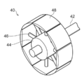
- the pressing device 40 includes a shaft 42 and a cylinder block 44 fixed to the shaft 42.
- the cylinder block 44 has a plurality of cylinder rods 46 extending radially outward. It is provided at equal intervals in the direction.
- a tire support piece 48 having an arcuate curved surface whose outer surface is set substantially equal to the radius of curvature of the inner surface of the tire case 17 is provided at the tip of the cylinder rod 46.
- FIG. 8A shows a state where the protruding amount of the cylinder rod 46 is the smallest
- FIG. 8B shows a state where the protruding amount of the cylinder rod 46 is the largest.
- Each cylinder rod 46 can project the same amount in the same direction in conjunction with each other.
- the tire case 17 and the belt layer 12 are sequentially attached to the outer periphery of the tire support piece 48 in a state where the protruding amount of the cylinder rod 46 is the smallest, and the cylinder rod 41 is protruded after the attachment (FIG. 8B). ).
- the crown portion 18 of the tire case 17 is pushed toward the inner peripheral surface of the belt layer 12, and the resin 26 of the melted belt layer 12 and the outer peripheral surface 18 ⁇ / b> A of the crown portion 18 are welded.
- the tire 10 is completed by providing an unvulcanized tread 30 on the outer side in the tire radial direction of the tire case 17 and the belt layer 12 and performing a vulcanization process.
- the belt layer 12 is configured by arranging a plurality of annular reinforcing bodies 28 covering the annular reinforcing cord 24 along the tire axial direction. Since the annular reinforcing body 28 is annular and endless, the one end and the other end do not overlap in the circumferential direction like a cord with ends. Therefore, the weight balance of the tire 10 can be improved. In addition, there is no step between the end and the crown as in the case of the ended cord, so a gap is formed when a reinforcing layer or the like is disposed along the outer surface in the tire axial direction of the belt layer. Hateful. Moreover, since the annular reinforcement 28 is not wound spirally and is not inclined with respect to the tire circumferential direction, the price tear of the tire 10 can be reduced.
- the resin covering the cord is inclined with respect to the outer surface 18A of the crown portion 18, and there is rarely a step between the cords. In some cases, such a step is unlikely to occur when the annular annular reinforcing bodies 28 are arranged.
- the annular reinforcing cord 24 can be easily formed.
- the tire case 17 is described as an example formed of a resin other than rubber, but the tire case (bead portion, side portion, crown portion) is formed of rubber.
- the belt layer 12 may be applied.
Landscapes
- Engineering & Computer Science (AREA)
- Mechanical Engineering (AREA)
- Tires In General (AREA)
Abstract
This tire has: a tire frame member provided with a bead section, a side section joined to the tire-radial-direction outer side of the bead section, and a crown section joined to the tire-axial-direction inner side of the side section; and a belt layer in which a plurality of annular circular reinforcing members, which are annular reinforcing cords covered with a resin, are disposed along the tire axial direction on the tire-radial-direction outer side of the tire frame member.
Description
本発明は、タイヤに関する。
The present invention relates to a tire.
従来から、タイヤ周方向に補強コードを螺旋状に巻回したベルト層を有するタイヤが製造されている。このベルト層は、通常、補強コードをゴム被覆して形成された帯状のゴムストリップをタイヤケースにタイヤ周方向に螺旋状に巻回すことにより形成されている(例えば、特開2008-168807号公報参照)。
Conventionally, a tire having a belt layer in which a reinforcing cord is spirally wound in the tire circumferential direction has been manufactured. This belt layer is usually formed by winding a belt-like rubber strip formed by covering a reinforcing cord with rubber in a spiral manner around a tire case (for example, Japanese Patent Application Laid-Open No. 2008-168807). reference).
ところで、上記のように、補強コードをゴム被覆したゴムストリップが螺旋状に巻回されたベルト層(ベルト層)では、ゴムストリップがタイヤ周方向に対して僅かではあるが傾斜しているため、プライステアが生じる可能性がある。
By the way, as described above, in the belt layer (belt layer) in which the rubber strip having the rubber cord covered with the reinforcing cord is spirally wound, the rubber strip is slightly inclined with respect to the tire circumferential direction. Price tears may occur.
また、ゴムストリップの巻回の始点端部及び終点端部に、タイヤケースと段差ができてしまう。さらに、始点端部と終点端部とがタイヤ周方向に重なり合った部分は、部分的に重くなり、重量バランスに影響が出る。
Also, there will be a step difference from the tire case at the start and end points of the rubber strip winding. Furthermore, the portion where the start point end portion and the end point end portion overlap in the tire circumferential direction becomes partially heavy, which affects the weight balance.
本発明は、上記事実を考慮して成されたものであり、プライステアが軽減されると共に、重量バランスを向上させたタイヤを提供することを課題とする。
The present invention has been made in consideration of the above facts, and an object of the present invention is to provide a tire in which the price tear is reduced and the weight balance is improved.
本発明の第1態様のタイヤは、ビード部と、前記ビード部のタイヤ径方向外側に連なるサイド部と、前記サイド部のタイヤ幅方向内側に連なるクラウン部と、を備えたタイヤ骨格部材と、円環状の補強コードが樹脂被覆された円環状の環状補強体が、前記タイヤ骨格部材のタイヤ径方向外側にタイヤ軸方向に沿って複数配置されたベルト層と、を有している。
The tire according to the first aspect of the present invention includes a tire skeleton member including a bead portion, a side portion continuous to the tire radial direction outer side of the bead portion, and a crown portion continuous to the tire width direction inner side of the side portion, An annular annular reinforcement body in which an annular reinforcement cord is coated with a resin has a belt layer arranged in plural along the tire axial direction on the outer side in the tire radial direction of the tire frame member.
第1態様のタイヤでは、ベルト層は、環状補強体が、タイヤ骨格部材のタイヤ径方向外側においてタイヤ軸方向に沿って複数配置されて形成されている。環状補強体は、円環状であり、無端であるため、一端部と他端部が周方向に重なることがない。したがって、タイヤの重量バランスを向上させることができる。また、環状補強体は、螺旋状に巻回されておらず、タイヤ周方向に対して傾斜していないので、プライステアを低減させることができる。
In the tire of the first aspect, the belt layer is formed by arranging a plurality of annular reinforcing bodies along the tire axial direction on the outer side in the tire radial direction of the tire frame member. Since the annular reinforcing body is annular and endless, the one end and the other end do not overlap in the circumferential direction. Therefore, the weight balance of the tire can be improved. Further, since the annular reinforcing body is not spirally wound and is not inclined with respect to the tire circumferential direction, the price tear can be reduced.
本発明の第2態様のタイヤは、前記補強コードは、接続部材により両端が接続されて円環状に形成されている。
In the tire according to the second aspect of the present invention, the reinforcing cord is formed in an annular shape with both ends connected by a connecting member.
第2態様のタイヤでは、両端を接続部材で接続することにより、補強コードを容易に円環状に形成することができる。
In the tire of the second aspect, the reinforcing cord can be easily formed in an annular shape by connecting both ends with connecting members.
本発明の第3態様のタイヤは、前記環状補強体は、タイヤ軸方向に複数配置された前記補強コードが樹脂被覆されて形成されている。
In the tire according to the third aspect of the present invention, the annular reinforcing body is formed by coating a plurality of the reinforcing cords arranged in the tire axial direction with a resin.
第3態様のタイヤでは、1本の環状補強コードに複数の補強コードが埋設されているので、環状補強コードのタイヤ軸方向の幅を広くすることができ、ベルト層の形成に必要な環状補強コードの本数を少なくして、タイヤの製造を容易にすることができる。
In the tire of the third aspect, since a plurality of reinforcing cords are embedded in one annular reinforcing cord, the width of the annular reinforcing cord in the tire axial direction can be widened, and the annular reinforcement necessary for forming the belt layer The number of cords can be reduced to facilitate the manufacture of the tire.
本発明の第4態様のタイヤは、前記タイヤ骨格部材は、樹脂製である、ことを特徴とする。
The tire according to the fourth aspect of the present invention is characterized in that the tire frame member is made of resin.
樹脂製のタイヤ骨格部材の場合には、樹脂被覆したコードを螺旋状に巻回すると、コードが傾きやすい。第4態様のタイヤでは、円環状の環状補強コードを用いるので、傾きを抑制することができる。
In the case of a resin tire skeleton member, the cord tends to tilt when the resin-coated cord is wound spirally. In the tire according to the fourth aspect, since an annular annular reinforcing cord is used, inclination can be suppressed.
以上説明したように、本発明は、タイヤの重量バランスを向上させることができると共に、プライステアを低減させることができる。
As described above, the present invention can improve the weight balance of the tire and reduce the price tear.
以下、本発明を実施するための形態を図面に基づき説明する。図面において、タイヤ周方向を矢印Sで示し、タイヤ軸方向(タイヤ幅方向と読み替えてもよい)を矢印Wで示し、タイヤ径方向を矢印Rで示している。タイヤ軸方向とは、タイヤ回転軸と平行な方向を意味する。
Hereinafter, embodiments for carrying out the present invention will be described with reference to the drawings. In the drawings, the tire circumferential direction is indicated by an arrow S, the tire axial direction (which may be read as the tire width direction) is indicated by an arrow W, and the tire radial direction is indicated by an arrow R. The tire axial direction means a direction parallel to the tire rotation axis.
また、タイヤ軸方向に沿ってタイヤ赤道面CLから遠い側を「タイヤ軸方向外側」、タイヤ軸方向に沿ってタイヤ赤道面CLに近い側を「タイヤ軸方向内側」として説明する。更に、タイヤ径方向に沿ってタイヤ軸線から遠い側を「タイヤ径方向外側」、タイヤ径方向に沿ってタイヤ軸線に近い側を「タイヤ径方向内側」とする。
Further, the side far from the tire equatorial plane CL along the tire axial direction will be described as “the tire axial direction outside”, and the side close to the tire equatorial plane CL along the tire axial direction will be described as “the tire axial direction inside”. Further, a side far from the tire axis along the tire radial direction is referred to as “tire radial outside”, and a side near the tire axis along the tire radial direction is referred to as “tire radial inner”.
各部の寸法測定方法は、JATMA(日本自動車タイヤ協会)が発行する2016年度版YEAR BOOKに記載の方法による。使用地又は製造地において、TRA規格、ETRTO規格が適用される場合は、各々の規格に従う。
Dimension measurement method of each part is according to the method described in the 2016 edition YEAR BOOK issued by JATMA (Japan Automobile Tire Association). When the TRA standard or ETRTO standard is applied at the place of use or manufacturing, the respective standards are followed.
図1に示されるように、本実施形態に係るタイヤ10は、環状のタイヤ骨格部材の一例であるタイヤケース17と、ベルト層12と、を有している。
As shown in FIG. 1, the tire 10 according to the present embodiment includes a tire case 17 that is an example of an annular tire frame member, and a belt layer 12.
タイヤケース17は、樹脂材料を用いて構成され、タイヤ周方向に円環状に形成されている。また、タイヤケース17は、タイヤ軸方向に間隔をあけて配置された一対のビード部14と、これら一対のビード部14からタイヤ径方向外側へそれぞれ延出する一対のサイド部16と、一対のサイド部16を連結するクラウン部18と、を含んで構成されている。ビード部14は、リム(図示せず)に接触する部位であり、後述する被覆層22が表面に設けられている。サイド部16は、タイヤ10の側部を形成し、ビード部14からクラウン部18に向かってタイヤ軸方向外側に凸となるように緩やかに湾曲している。
The tire case 17 is made of a resin material and is formed in an annular shape in the tire circumferential direction. In addition, the tire case 17 includes a pair of bead portions 14 arranged at intervals in the tire axial direction, a pair of side portions 16 extending from the pair of bead portions 14 outward in the tire radial direction, and a pair of And a crown portion 18 that connects the side portions 16. The bead part 14 is a part which contacts a rim (not shown), and a coating layer 22 described later is provided on the surface. The side portion 16 forms a side portion of the tire 10 and is gently curved so as to protrude outward in the tire axial direction from the bead portion 14 toward the crown portion 18.
クラウン部18は、一方のサイド部16のタイヤ径方向外側端と他方のサイド部16のタイヤ径方向外側端とを連結する部位であり、タイヤ径方向外側に配設されるトレッド30を支持する。
The crown portion 18 is a portion that connects the tire radial direction outer end of one side portion 16 and the tire radial direction outer end of the other side portion 16 and supports the tread 30 disposed on the outer side in the tire radial direction. .
また、本実施形態では、クラウン部18は、略一定厚みとされている。外周面18Aは、タイヤ軸方向断面において平坦状に形成されていてもよいし、またタイヤ径方向外側に膨らんだ湾曲形状であってもよい。なお、本実施形態のクラウン部18の外周面18Aは、ベルト層12が設けられるタイヤケース17の外周である。
In the present embodiment, the crown portion 18 has a substantially constant thickness. The outer peripheral surface 18A may be formed in a flat shape in the cross section in the tire axial direction, or may have a curved shape bulging outward in the tire radial direction. Note that the outer peripheral surface 18A of the crown portion 18 of the present embodiment is the outer periphery of the tire case 17 on which the belt layer 12 is provided.
また、タイヤケース17は、1つのビード部14、一つのサイド部16、及び半幅のクラウン部18を有する円環状のタイヤ半体17Hを一対形成し、これらのタイヤ半体17Hを互いに向かい合わせ、各々の半幅のクラウン部18の端部同士をタイヤ赤道面CLで接合して形成されている。この端部同士は、例えば溶接用樹脂材料17Aを用いて接合されている。
Further, the tire case 17 forms a pair of annular tire halves 17H having one bead portion 14, one side portion 16, and a half-width crown portion 18, and these tire halves 17H face each other. The ends of the half-width crown portions 18 are joined to each other at the tire equatorial plane CL. The ends are joined using, for example, a resin material for welding 17A.
ビード部14には、タイヤ周方向に沿って延びる円環状のビードコア20が埋設されている。このビードコア20は、ビードコード(図示せず)で構成されている。このビードコードは、スチールコード等の金属コード、有機繊維コード、樹脂被覆した有機繊維コード、または硬質樹脂などで構成される。なお、ビード部14の剛性を十分に確保できれば、ビードコア20自体を省略してもよい。
An annular bead core 20 extending along the tire circumferential direction is embedded in the bead portion 14. The bead core 20 includes a bead cord (not shown). The bead cord is composed of a metal cord such as a steel cord, an organic fiber cord, a resin-coated organic fiber cord, or a hard resin. The bead core 20 itself may be omitted if the rigidity of the bead portion 14 can be sufficiently secured.
また、ビード部14の表面のうち、少なくともリム(図示せず)との接触部分には、該リムとの間の気密性を高めるための被覆層22が形成されている。この被覆層22は、タイヤケース17よりも軟質で且つ耐候性が高いゴム材等の材料で構成されている。
Further, a coating layer 22 is formed on the surface of the bead portion 14 at least at a contact portion with a rim (not shown) to enhance airtightness with the rim. The covering layer 22 is made of a material such as a rubber material that is softer and weather resistant than the tire case 17.
また、本実施形態の被覆層22は、ビード部14のタイヤ軸方向内側の内面からタイヤ軸方向外側へ折り返され、サイド部16の外面を経由して、ベルト層12のタイヤ軸方向外側の端部近傍まで延びている。そして、被覆層22の延出端部は、後述するトレッド30によって覆われている。タイヤケース17のビード部14のみにより、リム(図示せず)との間のシール性(気密性)を確保できれば、被覆層22を省略してもよい。
Further, the coating layer 22 of the present embodiment is folded from the inner surface in the tire axial direction of the bead portion 14 to the outer side in the tire axial direction, and passes through the outer surface of the side portion 16 to the end on the outer side in the tire axial direction of the belt layer 12. It extends to the vicinity of the part. And the extended end part of the coating layer 22 is covered with the tread 30 mentioned later. The covering layer 22 may be omitted if the sealing property (airtightness) with the rim (not shown) can be ensured only by the bead portion 14 of the tire case 17.
なお、タイヤケース17を一体成型品としてもよく、タイヤケース17を3以上の樹脂部材に分けて製造し、これらを接合して形成してもよい。例えば、タイヤケース17を各部位(例えば、ビード部14、サイド部16、クラウン部18)ごとに分けて製造し、これらを接合して形成してもよい。このとき、タイヤケース17の各部位(例えば、ビード部14、サイド部16、クラウン部18)を異なる特徴を有する樹脂材料で形成してもよい。
The tire case 17 may be an integrally molded product, or the tire case 17 may be manufactured by dividing it into three or more resin members, and these may be joined. For example, the tire case 17 may be manufactured separately for each part (for example, the bead part 14, the side part 16, and the crown part 18), and these may be joined and formed. At this time, each part (for example, bead part 14, side part 16, crown part 18) of tire case 17 may be formed with a resin material which has a different characteristic.
また、タイヤケース17に、補強材(高分子材料や金属製の繊維、コード、不織布、織布等)を埋設配置してもよい。
Further, a reinforcing material (polymer material, metal fiber, cord, nonwoven fabric, woven fabric, etc.) may be embedded in the tire case 17.
ベルト層12は、タイヤケース17のタイヤ径方向外側に設けられている。ベルト層12は、後述する環状補強体28が、タイヤケース17の外周(クラウン部18の外周面18A)に、タイヤ軸方向に沿って複数本配置されて形成されている。
The belt layer 12 is provided on the outer side in the tire radial direction of the tire case 17. The belt layer 12 is formed by arranging a plurality of annular reinforcing bodies 28 to be described later on the outer periphery of the tire case 17 (the outer peripheral surface 18A of the crown portion 18) along the tire axial direction.
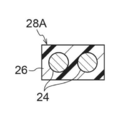
図2Aに示されるように、環状補強体28は、円環状の補強コード24が樹脂26で被覆されて、円環状に構成されている。図2Bに示されるように、環状補強体28は、断面が四角形状とされている。本実施形態では、環状補強体28は、樹脂26の中に1本の補強コード24が埋設されている。
As shown in FIG. 2A, the annular reinforcing member 28 is formed in an annular shape by covering an annular reinforcing cord 24 with a resin 26. As shown in FIG. 2B, the annular reinforcing body 28 has a square cross section. In the present embodiment, the annular reinforcing body 28 has a single reinforcing cord 24 embedded in the resin 26.
図3に示されるように、複数本の環状補強体28は、クラウン部18の外周面18Aにおいて、タイヤ周方向に対して傾斜せず、タイヤ周方向に沿って配置されている。隣り合う環状補強体28は、樹脂26同士が溶着されている。また、環状補強体28の内周面の樹脂26は、クラウン部18の外周面18Aと溶着されている。
3, the plurality of annular reinforcing bodies 28 are arranged along the tire circumferential direction on the outer circumferential surface 18A of the crown portion 18 without being inclined with respect to the tire circumferential direction. Adjacent annular reinforcing bodies 28 are welded with resins 26. The resin 26 on the inner peripheral surface of the annular reinforcement 28 is welded to the outer peripheral surface 18A of the crown portion 18.
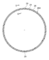
補強コード24は、金属繊維や有機繊維等のモノフィラメント(単線)、又はこれらの繊維を撚ったマルチフィラメント(撚り線)で構成されている。本実施形態では図4に示されるように、補強コード24の両端24Eが、接続部材29で接続されることで、補強コード24が円環状に形成されている。接続部材29は、筒状とされ、筒内に補強コード24の一端と他端が挿入された状態で外側から加締められている。接続部材29は、金属で形成することができる。ベルト層12を形成する各々の環状補強体28のタイヤ周方向における接続部材29の位置は、重なり合わないようにずらして配置されている。
The reinforcing cord 24 is composed of a monofilament (single wire) such as a metal fiber or an organic fiber, or a multifilament (twisted wire) obtained by twisting these fibers. In the present embodiment, as shown in FIG. 4, both ends 24 </ b> E of the reinforcing cord 24 are connected by a connecting member 29, so that the reinforcing cord 24 is formed in an annular shape. The connecting member 29 has a cylindrical shape, and is crimped from the outside with one end and the other end of the reinforcing cord 24 inserted into the cylinder. The connection member 29 can be formed of metal. The positions of the connecting members 29 in the tire circumferential direction of the respective annular reinforcing bodies 28 forming the belt layer 12 are arranged so as not to overlap each other.
なお、補強コード24は、溶接により両端を接合して円環状に形成してもよいし、撚り線であれば、各フィラメントの端部をずらして、円環状に撚ることにより形成してもよい。
The reinforcing cord 24 may be formed in an annular shape by joining both ends by welding, or in the case of a stranded wire, it may be formed by shifting the end of each filament and twisting in an annular shape. Good.
また、フィラメントに、樹脂26との接着性を向上させる接着用表面処理を施してもよい。熱可塑性材料との接着性を向上させるために施される金属の表面処理である。接着用表面処理としては、有機メッキ処理、浸漬表面処理などを用いることができる。
Further, the filament may be subjected to an adhesion surface treatment for improving the adhesion with the resin 26. This is a metal surface treatment applied to improve adhesion to a thermoplastic material. As the surface treatment for adhesion, organic plating treatment, immersion surface treatment, or the like can be used.
有機メッキ処理としては、特公平5-51671号、特開2001-1445号、などに開示されている、有機電解メッキ処理を用いることができる。
As the organic plating treatment, organic electrolytic plating treatment disclosed in Japanese Patent Publication No. 5-51671, Japanese Patent Application Laid-Open No. 2001-1445, and the like can be used.
浸漬表面処理としては、特開2003-170531号などに開示されている、表面処理を用いることができる。この表面処理では、水溶性アミン系化合物(又はアンモニア)水溶液へ、一定時間、ビードコア20、補強コード24を浸漬する。ここでの水溶性アミン系化合物は、ヒドラジンやその誘電体、低級アミン系化合物、ピリジン、アニリン、などを用いることができ、低級アミンとしては、メチルアミン、ジメチルアミン、トリメチルアミン、エチルアミン、ジエチルアミン、トリエチルアミン等を好適に使用することができる。
As the immersion surface treatment, a surface treatment disclosed in Japanese Patent Application Laid-Open No. 2003-170531 can be used. In this surface treatment, the bead core 20 and the reinforcing cord 24 are immersed in a water-soluble amine compound (or ammonia) aqueous solution for a predetermined time. As the water-soluble amine compound, hydrazine and its dielectric, lower amine compound, pyridine, aniline, etc. can be used. As the lower amine, methylamine, dimethylamine, trimethylamine, ethylamine, diethylamine, triethylamine are used. Etc. can be used suitably.
図1に示されるように、ベルト層12のタイヤ径方向外側にはゴム材料からなるトレッド30が配設されている。トレッド30はベルト層12及びタイヤケース17をタイヤ径方向外側から覆っている。トレッド30は、路面に接地し、耐摩耗性に優れたゴム材料で構成されている。なお、トレッド30のタイヤ径方向内側に、弾性率がタイヤ径方向外側のゴム材料よりも低く設定されたクッションゴムを含んでいてもよい。
As shown in FIG. 1, a tread 30 made of a rubber material is disposed outside the belt layer 12 in the tire radial direction. The tread 30 covers the belt layer 12 and the tire case 17 from the outer side in the tire radial direction. The tread 30 is made of a rubber material that contacts the road surface and has excellent wear resistance. The tread 30 may include a cushion rubber whose elastic modulus is set lower than that of the rubber material on the outer side in the tire radial direction on the inner side in the tire radial direction.
本実施形態のタイヤケース17及び補強コード24を覆う樹脂26に用いられる樹脂材料は、熱可塑性エラストマーを用いることができる。また、熱可塑性エラストマーに限られず、熱可塑性樹脂、熱硬化性樹脂、及びその他の汎用樹脂のほか、エンジニアリングプラスチック(スーパーエンジニアリングプラスチックを含む)等を用いることができる。なお、ここでの樹脂材料には、加硫ゴムは含まれない。
As the resin material used for the resin 26 that covers the tire case 17 and the reinforcing cord 24 of the present embodiment, a thermoplastic elastomer can be used. In addition to thermoplastic elastomers, engineering plastics (including super engineering plastics) can be used in addition to thermoplastic resins, thermosetting resins, and other general-purpose resins. The resin material here does not include vulcanized rubber.
熱可塑性樹脂(熱可塑性エラストマーを含む)とは、温度上昇と共に材料が軟化、流動し、冷却すると比較的硬く強度のある状態になる高分子化合物をいう。本明細書では、このうち、温度上昇と共に材料が軟化、流動し、冷却すると比較的硬く強度のある状態になり、かつ、ゴム状弾性を有する高分子化合物を熱可塑性エラストマーとし、温度上昇と共に材料が軟化、流動し、冷却すると比較的硬く強度のある状態になり、かつ、ゴム状弾性を有しない高分子化合物をエラストマーでない熱可塑性樹脂として、区別する。
Thermoplastic resin (including thermoplastic elastomer) refers to a polymer compound that softens and flows as the temperature rises and becomes relatively hard and strong when cooled. In the present specification, among these, the material softens and flows with increasing temperature, and becomes relatively hard and strong when cooled, and a high molecular compound having rubber-like elasticity is a thermoplastic elastomer, and the material increases with increasing temperature. Is softened, fluidized, and becomes a relatively hard and strong state when cooled, and a high molecular compound having no rubber-like elasticity is distinguished as a thermoplastic resin that is not an elastomer.
熱可塑性樹脂(熱可塑性エラストマーを含む)としては、ポリオレフィン系熱可塑性エラストマー(TPO)、ポリスチレン系熱可塑性エラストマー(TPS)、ポリアミド系熱可塑性エラストマー(TPA)、ポリウレタン系熱可塑性エラストマー(TPU)、ポリエステル系熱可塑性エラストマー(TPC)、及び、動的架橋型熱可塑性エラストマー(TPV)、ならびに、ポリオレフィン系熱可塑性樹脂、ポリスチレン系熱可塑性樹脂、ポリアミド系熱可塑性樹脂、及び、ポリエステル系熱可塑性樹脂等が挙げられる。
Thermoplastic resins (including thermoplastic elastomers) include polyolefin-based thermoplastic elastomers (TPO), polystyrene-based thermoplastic elastomers (TPS), polyamide-based thermoplastic elastomers (TPA), polyurethane-based thermoplastic elastomers (TPU), and polyesters. Thermoplastic thermoplastic elastomer (TPC), dynamically crosslinked thermoplastic elastomer (TPV), polyolefin thermoplastic resin, polystyrene thermoplastic resin, polyamide thermoplastic resin, polyester thermoplastic resin, etc. Can be mentioned.
また、上記の熱可塑性材料としては、例えば、ISO75-2又はASTM D648に規定されている荷重たわみ温度(0.45MPa荷重時)が78℃以上、JIS K7113に規定される引張降伏強さが10MPa以上、同じくJIS K7113に規定される引張破壊伸び(JIS K7113)が50%以上、JIS K7206に規定されるビカット軟化温度(A法)が130℃であるものを用いることができる。
Examples of the thermoplastic material include a deflection temperature under load (0.45 MPa load) specified in ISO 75-2 or ASTM D648 of 78 ° C. or higher, and a tensile yield strength specified in JIS K7113 of 10 MPa. As described above, a material having a tensile fracture elongation (JIS K7113) defined by JIS K7113 of 50% or more and a Vicat softening temperature (Method A) defined by JIS K7206 of 130 ° C. can be used.
熱硬化性樹脂とは、温度上昇と共に3次元的網目構造を形成し、硬化する高分子化合物をいい、例えば、フェノール樹脂、エポキシ樹脂、メラミン樹脂、ユリア樹脂等が挙げられる。
The thermosetting resin refers to a polymer compound that forms a three-dimensional network structure as the temperature rises and cures, and examples thereof include a phenol resin, an epoxy resin, a melamine resin, and a urea resin.
なお、樹脂材料には、既述の熱可塑性樹脂(熱可塑性エラストマーを含む)及び熱硬化性樹脂のほか、(メタ)アクリル系樹脂、EVA樹脂、塩化ビニル樹脂、フッ素系樹脂、シリコーン系樹脂等の汎用樹脂を用いてもよい。
In addition to the above-mentioned thermoplastic resins (including thermoplastic elastomers) and thermosetting resins, resin materials include (meth) acrylic resins, EVA resins, vinyl chloride resins, fluorine resins, silicone resins, etc. General-purpose resin may be used.
(タイヤの製造方法)
次に、本実施形態のタイヤ10の製造方法について説明する。まず、熱可塑性材料を用いた射出成型により、ビードコア20を含むタイヤ半体17Hを一組形成する。このタイヤ半体17Hの外面に被覆層22を形成する。 (Tire manufacturing method)
Next, the manufacturing method of thetire 10 of this embodiment is demonstrated. First, a set of tire halves 17H including bead cores 20 is formed by injection molding using a thermoplastic material. A coating layer 22 is formed on the outer surface of the tire half body 17H.
次に、本実施形態のタイヤ10の製造方法について説明する。まず、熱可塑性材料を用いた射出成型により、ビードコア20を含むタイヤ半体17Hを一組形成する。このタイヤ半体17Hの外面に被覆層22を形成する。 (Tire manufacturing method)
Next, the manufacturing method of the
一方で、補強コード24の両端24Eを接続部材29に挿入して外側から加締め、円環状に形成する。そして、必要となる表面処理を施した後、補強コード24を環状の金型内に設置し、金型を用いた射出成形により、補強コード24を樹脂26で被覆し、円環状の環状補強体28を形成する。なお、樹脂26の外側に接着層が必要な場合には、更に、別の金型を用意し、環状補強体28を当該金型内に設置して、接着剤を射出することにより、接着層を形成することができる。
On the other hand, both ends 24E of the reinforcing cord 24 are inserted into the connecting member 29 and crimped from the outside to form an annular shape. Then, after performing the necessary surface treatment, the reinforcing cord 24 is placed in an annular mold, and the reinforcing cord 24 is covered with a resin 26 by injection molding using the mold, and an annular annular reinforcing body is formed. 28 is formed. When an adhesive layer is required outside the resin 26, another mold is prepared, the annular reinforcing body 28 is installed in the mold, and an adhesive is injected to thereby bond the adhesive layer. Can be formed.
次に、図5に示すように、環状補強体28の各々の内周面により連続する空間Rが構成されるように、タイヤ軸方向に環状補強体28を必要な本数並べ、環状補強体28の側部の樹脂26同士を溶着させる。これにより、円環状のベルト層12が形成される。なお、複数の環状補強体28は、必ずしもこの工程で側部の樹脂26同士を溶着させる必要はなく、この工程では、溶着されていなくてもよい。
Next, as shown in FIG. 5, the necessary number of the annular reinforcing bodies 28 are arranged in the tire axial direction so that a continuous space R is formed by the inner peripheral surfaces of the annular reinforcing bodies 28, and the annular reinforcing bodies 28 are arranged. The side-side resins 26 are welded together. Thereby, the annular belt layer 12 is formed. The plurality of annular reinforcing bodies 28 do not necessarily have to be welded to the side resins 26 in this step, and may not be welded in this step.
次に、上記ベルト層12の内周の樹脂26を不図示の加熱装置により加熱して溶融させる。そして、図6に示すように、ベルト層12の内側に、円環状のタイヤ半体17Hをタイヤ軸方向の両側から挿入し、ベルト層12のタイヤ軸方向中央で溶接用樹脂材料17Aを用いて接合させてタイヤケース17を形成する。
Next, the resin 26 on the inner periphery of the belt layer 12 is heated and melted by a heating device (not shown). Then, as shown in FIG. 6, annular tire halves 17H are inserted into the belt layer 12 from both sides in the tire axial direction, and the welding resin material 17A is used at the center of the belt layer 12 in the tire axial direction. The tire case 17 is formed by bonding.
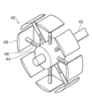
上記の組み付けは、押圧装置40を用いて行うことができる。押圧装置40は、図8A、図8Bに示すように、軸42と、軸42に固定されたシリンダブロック44を有し、シリンダブロック44には、径方向外側に延びる複数のシリンダロッド46が周方向に等間隔に設けられている。シリンダロッド46の先端には、外面がタイヤケース17内面の曲率半径と略同等に設定された円弧曲面を有するタイヤ支持片48が設けられている。図8Aは、シリンダロッド46の突出量が最も小さい状態を示しており、図8Bは、シリンダロッド46の突出量が最も大きい状態を示している。なお、各シリンダロッド46は、連動して同一方向に同一量突出可能となっている。
The above assembly can be performed using the pressing device 40. As shown in FIGS. 8A and 8B, the pressing device 40 includes a shaft 42 and a cylinder block 44 fixed to the shaft 42. The cylinder block 44 has a plurality of cylinder rods 46 extending radially outward. It is provided at equal intervals in the direction. A tire support piece 48 having an arcuate curved surface whose outer surface is set substantially equal to the radius of curvature of the inner surface of the tire case 17 is provided at the tip of the cylinder rod 46. FIG. 8A shows a state where the protruding amount of the cylinder rod 46 is the smallest, and FIG. 8B shows a state where the protruding amount of the cylinder rod 46 is the largest. Each cylinder rod 46 can project the same amount in the same direction in conjunction with each other.
タイヤケース17及びベルト層12は、図7に示されるように、シリンダロッド46の突出量が最も小さい状態でタイヤ支持片48の外周に順次取り付けられ、取り付け後にシリンダロッド41を突出させる(図8B)。これにより、ベルト層12の内周面に向かってタイヤケース17のクラウン部18が押され、溶融状態のベルト層12の樹脂26とクラウン部18の外周面18Aとが溶着される。
As shown in FIG. 7, the tire case 17 and the belt layer 12 are sequentially attached to the outer periphery of the tire support piece 48 in a state where the protruding amount of the cylinder rod 46 is the smallest, and the cylinder rod 41 is protruded after the attachment (FIG. 8B). ). As a result, the crown portion 18 of the tire case 17 is pushed toward the inner peripheral surface of the belt layer 12, and the resin 26 of the melted belt layer 12 and the outer peripheral surface 18 </ b> A of the crown portion 18 are welded.
その後、詳細は省略するが、タイヤケース17及びベルト層12のタイヤ径方向外側に未加硫のトレッド30を設けて加硫工程を経ることで、タイヤ10が完成する。
Thereafter, although details are omitted, the tire 10 is completed by providing an unvulcanized tread 30 on the outer side in the tire radial direction of the tire case 17 and the belt layer 12 and performing a vulcanization process.
本実施形態のタイヤ10では、円環状の補強コード24を被覆した環状補強体28をタイヤ軸方向に沿って複数配置してベルト層12を構成している。この環状補強体28は、円環状であり、無端であるため、有端のコードのように一端部と他端部が周方向に重なることがない。したがって、タイヤ10の重量バランスを向上させることができる。また、有端のコードのように端部とクラウン部との間に段差ができないので、ベルト層のタイヤ軸方向外側面に沿って、補強用のレイヤーなどを配置する際に、隙間が形成されにくい。また、環状補強体28は、螺旋状に巻回されておらず、タイヤ周方向に対して傾斜していないので、タイヤ10のプライステアを低減させることができる。
In the tire 10 of the present embodiment, the belt layer 12 is configured by arranging a plurality of annular reinforcing bodies 28 covering the annular reinforcing cord 24 along the tire axial direction. Since the annular reinforcing body 28 is annular and endless, the one end and the other end do not overlap in the circumferential direction like a cord with ends. Therefore, the weight balance of the tire 10 can be improved. In addition, there is no step between the end and the crown as in the case of the ended cord, so a gap is formed when a reinforcing layer or the like is disposed along the outer surface in the tire axial direction of the belt layer. Hateful. Moreover, since the annular reinforcement 28 is not wound spirally and is not inclined with respect to the tire circumferential direction, the price tear of the tire 10 can be reduced.
また、タイヤ周方向にコードを螺旋状に巻回してベルト層を形成する場合には、コードを被覆する樹脂がクラウン部18の外側面18Aに対して傾斜して、稀にコード間に段差が生じる場合があるが、円環状の環状補強体28を並べる場合には、このような段差が生じにくい。
Further, when the belt is formed by winding the cord spirally in the tire circumferential direction, the resin covering the cord is inclined with respect to the outer surface 18A of the crown portion 18, and there is rarely a step between the cords. In some cases, such a step is unlikely to occur when the annular annular reinforcing bodies 28 are arranged.
また、本実施形態のように、ベルト層12の補強コード24を、接続部材29で両端を接続することにより、容易に円環状の補強コード24を形成することができる。
Further, as in the present embodiment, by connecting both ends of the reinforcing cord 24 of the belt layer 12 with the connecting member 29, the annular reinforcing cord 24 can be easily formed.
なお、本実施形態では、1本の環状補強体28は、樹脂26の中に1本の補強コード24が埋設されている例を説明したが、1本の環状補強体28に複数の補強コード24が埋設されていてもよい。図9A、図9Bには、2本の補強コード24が埋設されている例が図示されている。補強コード24を円環状にする接続部材29は、タイヤ周方向において異なる位置に配置される。
In the present embodiment, an example in which one reinforcing cord 24 is embedded in the resin 26 in one annular reinforcing member 28 has been described, but a plurality of reinforcing cords are provided in one annular reinforcing member 28. 24 may be embedded. 9A and 9B show an example in which two reinforcing cords 24 are embedded. The connection members 29 that make the reinforcing cords 24 have an annular shape are arranged at different positions in the tire circumferential direction.
また、本実施形態では、タイヤケース17をゴム以外の樹脂で形成されたものを例に説明したが、タイヤケース(ビード部、サイド部、クラウン部)が、ゴムで形成されているものについて、ベルト層12を適用してもよい。
Further, in the present embodiment, the tire case 17 is described as an example formed of a resin other than rubber, but the tire case (bead portion, side portion, crown portion) is formed of rubber. The belt layer 12 may be applied.
以上、実施形態を挙げて本発明の実施の形態を説明したが、これらの実施形態は一例であり、要旨を逸脱しない範囲内で種々変更して実施でき、製造工程の順序を適宜変更することが可能である。また、本発明の権利範囲がこれらの実施形態に限定されないことは言うまでもない。
The embodiments of the present invention have been described above with reference to the embodiments. However, these embodiments are merely examples, and various modifications can be made without departing from the scope of the invention, and the order of the manufacturing steps can be changed as appropriate. Is possible. It goes without saying that the scope of rights of the present invention is not limited to these embodiments.
日本出願、特願2016-204374の開示はその全体が参照により本明細書に取り込まれる。
本明細書に記載された全ての文献、特許出願、および技術規格は、個々の文献、特許出願、および技術規格が参照により取り込まれることが具体的かつ個々に記された場合と同程度に、本明細書中に参照により取り込まれる。 The disclosure of Japanese application, Japanese Patent Application No. 2016-204374 is incorporated herein by reference in its entirety.
All documents, patent applications, and technical standards mentioned in this specification are to the same extent as if each individual document, patent application, and technical standard were specifically and individually described to be incorporated by reference, Incorporated herein by reference.
Claims (4)
- ビード部と、前記ビード部のタイヤ径方向外側に連なるサイド部と、前記サイド部のタイヤ幅方向内側に連なるクラウン部と、を備えたタイヤ骨格部材と、
円環状の補強コードが樹脂被覆された円環状の環状補強体が、前記タイヤ骨格部材のタイヤ径方向外側にタイヤ軸方向に沿って複数配置されたベルト層と、
を有するタイヤ。 A tire frame member comprising: a bead portion; a side portion continuous to a tire radial direction outer side of the bead portion; and a crown portion continuous to a tire width direction inner side of the side portion;
A belt layer in which a plurality of annular reinforcing bodies each having an annular reinforcing cord coated with a resin are arranged along the tire axial direction on the outer side in the tire radial direction of the tire frame member;
Tire with. - 前記補強コードは、接続部材により両端が接続されて円環状に形成されている、請求項1に記載のタイヤ。 The tire according to claim 1, wherein the reinforcing cord is formed in an annular shape with both ends connected by a connecting member.
- 前記環状補強体は、タイヤ軸方向に複数配置された前記補強コードが樹脂被覆されて形成されている、請求項1または請求項2に記載のタイヤ。 3. The tire according to claim 1, wherein the annular reinforcing body is formed by coating a plurality of the reinforcing cords arranged in the tire axial direction with a resin.
- 前記タイヤ骨格部材は、樹脂製である、ことを特徴とする請求項1~請求項3のいずれか1項に記載のタイヤ。 The tire according to any one of claims 1 to 3, wherein the tire frame member is made of resin.
Priority Applications (3)
| Application Number | Priority Date | Filing Date | Title |
|---|---|---|---|
| EP17862357.5A EP3530483A4 (en) | 2016-10-18 | 2017-10-10 | Tire |
| US16/341,921 US20190241018A1 (en) | 2016-10-18 | 2017-10-10 | Tire |
| CN201780063839.1A CN109863043A (en) | 2016-10-18 | 2017-10-10 | Tire |
Applications Claiming Priority (2)
| Application Number | Priority Date | Filing Date | Title |
|---|---|---|---|
| JP2016-204374 | 2016-10-18 | ||
| JP2016204374A JP2018065425A (en) | 2016-10-18 | 2016-10-18 | tire |
Publications (1)
| Publication Number | Publication Date |
|---|---|
| WO2018074284A1 true WO2018074284A1 (en) | 2018-04-26 |
Family
ID=62019128
Family Applications (1)
| Application Number | Title | Priority Date | Filing Date |
|---|---|---|---|
| PCT/JP2017/036664 WO2018074284A1 (en) | 2016-10-18 | 2017-10-10 | Tire |
Country Status (5)
| Country | Link |
|---|---|
| US (1) | US20190241018A1 (en) |
| EP (1) | EP3530483A4 (en) |
| JP (1) | JP2018065425A (en) |
| CN (1) | CN109863043A (en) |
| WO (1) | WO2018074284A1 (en) |
Cited By (3)
| Publication number | Priority date | Publication date | Assignee | Title |
|---|---|---|---|---|
| WO2019230759A1 (en) * | 2018-05-31 | 2019-12-05 | 株式会社ブリヂストン | Method for manufacturing pneumatic tire |
| WO2021070582A1 (en) * | 2019-10-08 | 2021-04-15 | 住友ゴム工業株式会社 | Pneumatic tire |
| EP3900949A4 (en) * | 2018-12-19 | 2022-08-24 | Bridgestone Corporation | Run-flat tire |
Families Citing this family (1)
| Publication number | Priority date | Publication date | Assignee | Title |
|---|---|---|---|---|
| CN110561979B (en) * | 2019-08-30 | 2021-07-20 | 青岛慕沃科技有限公司 | Method for manufacturing polyurethane pneumatic tire |
Citations (8)
| Publication number | Priority date | Publication date | Assignee | Title |
|---|---|---|---|---|
| JPH0551671A (en) | 1991-08-21 | 1993-03-02 | Nikko Kyodo Co Ltd | High-strength and high-conductivity copper alloy for electronic equipment excellent in bendability and stress relaxation property |
| JP2001001445A (en) | 1999-06-24 | 2001-01-09 | Toa Denka:Kk | Composite of conductive object and resin, and production thereof |
| JP2003170531A (en) | 2001-12-10 | 2003-06-17 | Taisei Plas Co Ltd | Composite of metal and resin and method for manufacturing the composite |
| JP2003260906A (en) * | 2002-03-07 | 2003-09-16 | Bridgestone Corp | Pneumatic radial tire and its manufacturing method |
| JP2008168807A (en) | 2007-01-12 | 2008-07-24 | Bridgestone Corp | Pneumatic tire, and method of manufacture thereof |
| JP2012035500A (en) * | 2010-08-06 | 2012-02-23 | Bridgestone Corp | Method of manufacturing tire and tire |
| JP2012035435A (en) * | 2010-08-04 | 2012-02-23 | Bridgestone Corp | Method of manufacturing tire and tire |
| JP2016204374A (en) | 2015-04-21 | 2016-12-08 | 大日本住友製薬株式会社 | Medicine comprising condensed pyrazole derivative |
Family Cites Families (9)
| Publication number | Priority date | Publication date | Assignee | Title |
|---|---|---|---|---|
| FR2529834A1 (en) * | 1982-07-08 | 1984-01-13 | Michelin & Cie | PNEUMATIC ENVELOPE COMPRISING A BODY WITHOUT REINFORCING REINFORCEMENT FRAME IN THE FLANKS AND AT THE TOP, AND A SUMMIT REINFORCEMENT |
| DE3401016A1 (en) * | 1983-07-27 | 1985-02-14 | Jonny 4000 Düsseldorf Janus | BELT TIRES AND METHOD FOR PRODUCING THE SAME |
| US5010937A (en) * | 1986-10-18 | 1991-04-30 | Jonny Janus | Belted tire for vehicles |
| AU6580194A (en) * | 1993-04-26 | 1994-11-21 | Gyula Subotics | Vehicle tyre |
| FR2921863B1 (en) * | 2007-10-05 | 2009-12-18 | Michelin Soc Tech | PNEUMATIC USING A FIBER REINFORCING STRUCTURE OF APLATIE SECTION |
| EP2821250B1 (en) * | 2012-02-29 | 2017-04-19 | Bridgestone Corporation | Tire |
| JP6301306B2 (en) * | 2013-02-20 | 2018-03-28 | 株式会社ブリヂストン | Tire, tire manufacturing apparatus, and tire manufacturing method |
| JP6053016B2 (en) * | 2013-04-18 | 2016-12-27 | 株式会社ブリヂストン | tire |
| JP6284930B2 (en) * | 2013-04-22 | 2018-02-28 | 株式会社ブリヂストン | tire |
-
2016
- 2016-10-18 JP JP2016204374A patent/JP2018065425A/en active Pending
-
2017
- 2017-10-10 US US16/341,921 patent/US20190241018A1/en not_active Abandoned
- 2017-10-10 CN CN201780063839.1A patent/CN109863043A/en active Pending
- 2017-10-10 EP EP17862357.5A patent/EP3530483A4/en not_active Withdrawn
- 2017-10-10 WO PCT/JP2017/036664 patent/WO2018074284A1/en unknown
Patent Citations (8)
| Publication number | Priority date | Publication date | Assignee | Title |
|---|---|---|---|---|
| JPH0551671A (en) | 1991-08-21 | 1993-03-02 | Nikko Kyodo Co Ltd | High-strength and high-conductivity copper alloy for electronic equipment excellent in bendability and stress relaxation property |
| JP2001001445A (en) | 1999-06-24 | 2001-01-09 | Toa Denka:Kk | Composite of conductive object and resin, and production thereof |
| JP2003170531A (en) | 2001-12-10 | 2003-06-17 | Taisei Plas Co Ltd | Composite of metal and resin and method for manufacturing the composite |
| JP2003260906A (en) * | 2002-03-07 | 2003-09-16 | Bridgestone Corp | Pneumatic radial tire and its manufacturing method |
| JP2008168807A (en) | 2007-01-12 | 2008-07-24 | Bridgestone Corp | Pneumatic tire, and method of manufacture thereof |
| JP2012035435A (en) * | 2010-08-04 | 2012-02-23 | Bridgestone Corp | Method of manufacturing tire and tire |
| JP2012035500A (en) * | 2010-08-06 | 2012-02-23 | Bridgestone Corp | Method of manufacturing tire and tire |
| JP2016204374A (en) | 2015-04-21 | 2016-12-08 | 大日本住友製薬株式会社 | Medicine comprising condensed pyrazole derivative |
Non-Patent Citations (1)
| Title |
|---|
| See also references of EP3530483A4 * |
Cited By (4)
| Publication number | Priority date | Publication date | Assignee | Title |
|---|---|---|---|---|
| WO2019230759A1 (en) * | 2018-05-31 | 2019-12-05 | 株式会社ブリヂストン | Method for manufacturing pneumatic tire |
| EP3900949A4 (en) * | 2018-12-19 | 2022-08-24 | Bridgestone Corporation | Run-flat tire |
| WO2021070582A1 (en) * | 2019-10-08 | 2021-04-15 | 住友ゴム工業株式会社 | Pneumatic tire |
| CN113543986A (en) * | 2019-10-08 | 2021-10-22 | 住友橡胶工业株式会社 | Pneumatic tire |
Also Published As
| Publication number | Publication date |
|---|---|
| EP3530483A1 (en) | 2019-08-28 |
| CN109863043A (en) | 2019-06-07 |
| US20190241018A1 (en) | 2019-08-08 |
| JP2018065425A (en) | 2018-04-26 |
| EP3530483A4 (en) | 2019-08-28 |
Similar Documents
| Publication | Publication Date | Title |
|---|---|---|
| JP6618472B2 (en) | tire | |
| WO2018101175A1 (en) | Tire | |
| WO2018074284A1 (en) | Tire | |
| JP6204732B2 (en) | tire | |
| EP3176002A1 (en) | Tire | |
| EP3290230B1 (en) | Tire | |
| WO2017200061A1 (en) | Tire | |
| JP6204672B2 (en) | tire | |
| JP6306564B2 (en) | tire | |
| EP3290229B1 (en) | Tire | |
| EP3020571B1 (en) | Tire | |
| EP3173252A1 (en) | Tire | |
| EP3795380A1 (en) | Pneumatic tire | |
| WO2016017555A1 (en) | Tire | |
| EP3812167A1 (en) | Resin-covered cords and pneumatic tire | |
| WO2019235328A1 (en) | Pneumatic tire and manufacturing method for pneumatic tire | |
| WO2020004045A1 (en) | Tire and tire manufacturing method | |
| WO2019230353A1 (en) | Tire | |
| JP2023087599A (en) | tire | |
| JPWO2019244741A1 (en) | Pneumatic tires |
Legal Events
| Date | Code | Title | Description |
|---|---|---|---|
| 121 | Ep: the epo has been informed by wipo that ep was designated in this application |
Ref document number: 17862357 Country of ref document: EP Kind code of ref document: A1 |
|
| NENP | Non-entry into the national phase |
Ref country code: DE |
|
| ENP | Entry into the national phase |
Ref document number: 2017862357 Country of ref document: EP Effective date: 20190520 |