WO2018062332A1 - Work vehicle - Google Patents
Work vehicle Download PDFInfo
- Publication number
- WO2018062332A1 WO2018062332A1 PCT/JP2017/035080 JP2017035080W WO2018062332A1 WO 2018062332 A1 WO2018062332 A1 WO 2018062332A1 JP 2017035080 W JP2017035080 W JP 2017035080W WO 2018062332 A1 WO2018062332 A1 WO 2018062332A1
- Authority
- WO
- WIPO (PCT)
- Prior art keywords
- vehicle speed
- vehicle
- driving force
- work
- traveling
- Prior art date
Links
Images


Classifications
-
- E—FIXED CONSTRUCTIONS
- E02—HYDRAULIC ENGINEERING; FOUNDATIONS; SOIL SHIFTING
- E02F—DREDGING; SOIL-SHIFTING
- E02F9/00—Component parts of dredgers or soil-shifting machines, not restricted to one of the kinds covered by groups E02F3/00 - E02F7/00
- E02F9/20—Drives; Control devices
- E02F9/22—Hydraulic or pneumatic drives
- E02F9/2253—Controlling the travelling speed of vehicles, e.g. adjusting travelling speed according to implement loads, control of hydrostatic transmission
-
- E—FIXED CONSTRUCTIONS
- E02—HYDRAULIC ENGINEERING; FOUNDATIONS; SOIL SHIFTING
- E02F—DREDGING; SOIL-SHIFTING
- E02F9/00—Component parts of dredgers or soil-shifting machines, not restricted to one of the kinds covered by groups E02F3/00 - E02F7/00
- E02F9/20—Drives; Control devices
-
- E—FIXED CONSTRUCTIONS
- E02—HYDRAULIC ENGINEERING; FOUNDATIONS; SOIL SHIFTING
- E02F—DREDGING; SOIL-SHIFTING
- E02F9/00—Component parts of dredgers or soil-shifting machines, not restricted to one of the kinds covered by groups E02F3/00 - E02F7/00
- E02F9/20—Drives; Control devices
- E02F9/2058—Electric or electro-mechanical or mechanical control devices of vehicle sub-units
- E02F9/2079—Control of mechanical transmission
-
- E—FIXED CONSTRUCTIONS
- E02—HYDRAULIC ENGINEERING; FOUNDATIONS; SOIL SHIFTING
- E02F—DREDGING; SOIL-SHIFTING
- E02F9/00—Component parts of dredgers or soil-shifting machines, not restricted to one of the kinds covered by groups E02F3/00 - E02F7/00
- E02F9/20—Drives; Control devices
- E02F9/22—Hydraulic or pneumatic drives
- E02F9/2278—Hydraulic circuits
- E02F9/2292—Systems with two or more pumps
-
- E—FIXED CONSTRUCTIONS
- E02—HYDRAULIC ENGINEERING; FOUNDATIONS; SOIL SHIFTING
- E02F—DREDGING; SOIL-SHIFTING
- E02F9/00—Component parts of dredgers or soil-shifting machines, not restricted to one of the kinds covered by groups E02F3/00 - E02F7/00
- E02F9/20—Drives; Control devices
- E02F9/22—Hydraulic or pneumatic drives
- E02F9/2278—Hydraulic circuits
- E02F9/2296—Systems with a variable displacement pump
-
- F—MECHANICAL ENGINEERING; LIGHTING; HEATING; WEAPONS; BLASTING
- F16—ENGINEERING ELEMENTS AND UNITS; GENERAL MEASURES FOR PRODUCING AND MAINTAINING EFFECTIVE FUNCTIONING OF MACHINES OR INSTALLATIONS; THERMAL INSULATION IN GENERAL
- F16H—GEARING
- F16H61/00—Control functions within control units of change-speed- or reversing-gearings for conveying rotary motion ; Control of exclusively fluid gearing, friction gearing, gearings with endless flexible members or other particular types of gearing
- F16H61/38—Control of exclusively fluid gearing
- F16H61/40—Control of exclusively fluid gearing hydrostatic
- F16H61/4008—Control of circuit pressure
Definitions
- the present invention relates to a work vehicle.
- Patent Document 1 when the load pressure of the working hydraulic circuit exceeds a predetermined value, the maximum value of the displacement of the hydraulic motor is reduced to the minimum limit value corresponding to the maximum load pressure of the working hydraulic circuit.
- a travel control device is described.
- the reaction force from the object to be excavated acts on the hydraulic cylinder of the working machine and the work is performed before driving the arm
- the machine load may be excessive. In such a case, even if the travel driving force is limited after the load pressure of the working hydraulic circuit exceeds a predetermined value, there is a possibility that the work efficiency of the excavation will not be improved.
- a work vehicle includes a work machine having an arm and a bucket, a vehicle speed detection device that detects a vehicle speed, and a traveling drive device that outputs traveling driving force that increases as the vehicle speed decreases during excavation.
- the control device causes the vehicle speed detected by the vehicle speed detection device to fall below a predetermined first vehicle speed threshold. It is characterized by having a restriction
- the present invention it is possible to limit the travel driving force in the process of causing the working machine to sufficiently penetrate the digging object, prevent the working machine load from becoming excessive, and improve the working efficiency of the digging.
- FIG. 1 is a view showing a schematic configuration of a wheel loader according to a first embodiment.
- the figure which shows the relationship between traveling load pressure Pt and motor displacement qm.
- the travel performance diagram which shows the relationship between the vehicle speed V of the working vehicle and the maximum travel driving force A which concern on 1st Embodiment.
- 5 is a flowchart showing processing contents of driving force limit control by the controller according to the first embodiment.
- the time chart which shows the change of the driving force and the vehicle speed in the excavation work of the work vehicle concerning a 1st embodiment.
- working performance diagram which shows the relationship between the vehicle speed V of the working vehicle which concerns on 2nd Embodiment, and the largest driving
- FIG. The time chart which shows the change of the driving force and the vehicle speed in the excavation work of the work vehicle concerning a 2nd embodiment.
- the travel performance diagram which shows the relationship between the vehicle speed V of the working vehicle and the maximum travel driving force A which concern on the modification of 2nd Embodiment.
- the time chart which shows the change of the driving force and the vehicle speed in digging work of the work vehicle concerning a 3rd embodiment.
- working performance diagram which shows the relationship between the vehicle speed V of the working vehicle, and the largest driving
- the flowchart which shows the processing contents of the driving force restriction control by the controller concerning a 4th embodiment.
- (A) is a figure which shows the characteristic of correction value (DELTA) A which increases according to the increase in inclination-angle (theta) in the working vehicle which concerns on the modification 1 of 4th Embodiment
- (b) is 4th Embodiment
- the traveling performance diagram which shows the relationship between the vehicle speed V of the working vehicle and the maximum traveling drive force A which concern on the modification 3 of 3.
- FIG. The figure explaining calculation of time change rate alpha of the vehicle speed.
- the flowchart which shows the processing contents of the driving force restriction control by the controller concerning a 5th embodiment.
- the figure which shows an example of a structure of the working vehicle which concerns on 6th Embodiment.
- the figure which shows a motor request torque map (motor characteristic) and a maximum torque map.
- the figure which shows schematic structure of the working vehicle which concerns on 7th Embodiment.
- the figure which shows schematic structure of the working vehicle which concerns on the modification 1 of 7th Embodiment.
- FIG. 1 is a side view of a wheel loader which is an example of a work vehicle.
- the wheel loader has a front vehicle body 110 having an arm 111, a bucket 112, front wheels 113 (front wheels), etc., a cab 121, a machine room 122, rear wheels 113 (rear wheels) etc.
- the rear vehicle body 120 is configured.
- the arm 111 is rotated (up and down) in the vertical direction by driving the arm cylinder 117, and the bucket 112 is rotated (cloud or dump) in the vertical direction by driving the bucket cylinder 115.
- the front vehicle body 110 and the rear vehicle body 120 are rotatably connected to each other by the center pin 101, and the expansion and contraction of the steering cylinder 116 bends the front vehicle body 110 to the left and right with respect to the rear vehicle body 120.
- the working machine includes an arm 111 and a bucket 112, and an arm cylinder 117 and a bucket cylinder 115 provided in the working hydraulic circuit HC2 (see FIG. 2), and is for working driven by the engine 1 It is driven by pressure oil discharged from the hydraulic pump 4 (see FIG. 2).
- pressure oil discharged from the working hydraulic pump 4 is supplied to the arm cylinder 117 and the bucket cylinder 115 via a control valve provided in the working hydraulic circuit HC2.
- the control valve of the working hydraulic circuit HC2 operates, and the working oil is appropriately distributed to the arm cylinder 117 and the bucket cylinder 115, and the arm 111 and the bucket 112 Can perform predetermined operations.
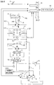
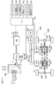
- FIG. 2 is a view showing a schematic configuration of the wheel loader according to the first embodiment.
- the wheel loader includes a traveling drive device that outputs traveling driving force.
- the traveling drive device includes a traveling hydraulic circuit HC1 and a power transmission mechanism (not shown).
- the traveling hydraulic circuit HC1 is a pair of a variable displacement hydraulic pump (hereinafter referred to as HST pump 2) driven by the engine 1 and a variable displacement hydraulic motor (hereinafter referred to as HST motor 3). It is comprised by the HST (Hydro Static Transmission) circuit closed-circuit connected by main pipe line LA, LB.
- HST Hydro Static Transmission
- the rotation of the HST motor 3 is shifted by a transmission (not shown), and the rotation after the shift is transmitted to the wheel 113 via a power transmission mechanism such as a propeller shaft (not shown) or an axle (not shown).
- the wheel loader travels by rotating.
- the pressure oil discharged from the charge pump 5 driven by the engine 1 is led to the tilt cylinder 8 via the forward / reverse switching valve 6.
- the forward / backward switching valve 6 is operated by the operation lever 6a, and as shown in the figure, when the forward / backward switching valve 6 is in the neutral position, the pressure oil discharged from the charge pump 5 passes through the throttle 7 and the forward / backward switching valve 6 They act on the oil chambers 8a and 8b of the tilt cylinder 8, respectively. In this state, the pressures acting on the oil chambers 8a and 8b are equal to each other, and the piston 8c is in the neutral position. Therefore, the displacement qp of the HST pump 2 is zero, and the pump discharge amount Q is zero.
- the accelerator pedal 9 is provided with an operation amount detector 9a for detecting the amount of operation of the accelerator pedal 9, and a signal from the operation amount detector 9a is input to the controller 10.
- the controller 10 calculates a target engine rotation speed Nt based on the operation amount detected by the operation amount detector 9a, and outputs a signal corresponding to the target engine rotation speed Nt to the engine control unit 1a.
- the engine control unit 1a compares the actual engine rotational speed Na detected by the engine rotational speed sensor 1b with the target engine rotational speed Nt from the controller 10, and brings the actual engine rotational speed Na closer to the target engine rotational speed Nt. Control the fuel injection system (not shown).
- the flow rate (discharge amount) of the pressure oil discharged from the charge pump 5 is proportional to the engine rotation speed, and the differential pressure ⁇ P of the throttle 7 is proportional to the engine rotation speed. Therefore, the pump displacement qp is also proportional to the engine rotational speed.
- the pressure oil discharged from the charge pump 5 passes through the throttle 7 and the check valves 11A and 11B, is led to the main lines LA and LB, and is replenished to the HST circuit (HC1).
- the pressure on the downstream side of the throttle 7 is limited by the charge relief valve 12, and the maximum pressure of the main lines LA, LB is limited by the overload relief valve 13.
- the displacement volume qm (motor displacement angle) of the HST motor 3 is controlled by the regulator 14.
- the regulator 14 is an electric regulator including an electromagnetic switching valve, an electromagnetic proportional valve, and the like.
- the displacement control lever 140 is driven to change the displacement volume qm.
- a stopper 15 is provided in the motor displacement control unit, the displacement control lever 140 abuts on the stopper 15, and the minimum value of the motor displacement volume qm is mechanically limited to a predetermined value qmin.
- the tilt control lever 140 abuts on the stopper 15 to hold the motor displacement qm at the minimum value qmin.
- the control current output to the regulator 14 increases, the motor displacement qm increases.
- the controller 10 is configured to include an arithmetic processing unit having a CPU, a ROM, a RAM, other peripheral circuits, and the like.
- the controller 10 functionally includes a valid / invalid mode setting unit 10a and a limit control unit 10b.
- a vehicle speed sensor 26 is connected to the controller 10.
- the vehicle speed sensor 26 detects information corresponding to the traveling speed (vehicle speed) V of the vehicle, and outputs a detection signal to the controller 10.
- the vehicle speed sensor 26 can be configured, for example, by a rotational speed detection device that detects the rotational speed of the output shaft of a transmission (not shown) connected to the HST motor 3.
- a signal from the running load pressure sensor 21 for detecting the pressure (running load pressure Pt) of the high pressure side main pipelines LA, LB selected by the high pressure selection valve 16 and a signal from the mode switch 23 are respectively It is input.
- the mode switch 23 is a switch by which an operating position of either the traveling position or the working position is selected by the operator, and outputs an operation signal corresponding to the selected operating position to the controller 10.
- the valid / invalid mode setting unit 10a determines whether or not the following valid individual condition 1 and valid individual condition 2 are satisfied. When both of the valid individual condition 1 and the valid individual condition 2 are satisfied, the valid / invalid mode setting unit 10a determines that the valid condition is satisfied, and sets the valid mode. If either the valid individual condition 1 or the valid individual condition 2 is not satisfied, the valid / invalid mode setting unit 10a determines that the valid condition is not satisfied, and sets the invalid mode. (Effective Individual Condition 1) The vehicle speed V detected by the vehicle speed sensor 26 is equal to or more than the threshold value Vb1 for effective determination (Effective Individual Condition 2) The mode switch 23 is operated to the work position
- the limit control unit 10 b controls the motor displacement qm in accordance with the traveling load pressure Pt detected by the traveling load pressure sensor 21.
- FIG. 3 is a diagram showing the relationship between the traveling load pressure Pt and the motor displacement qm.
- the storage device of the controller 10 stores the non-limiting characteristic C0 and the limiting characteristic C1 in the form of a look-up table.
- the non-limitation characteristic C0 is a characteristic in which the motor displacement volume qm is a minimum value qmin when the traveling load pressure Pt is less than a predetermined value Pt0.
- the motor displacement volume increases linearly from the minimum value qmin to the maximum value qmax in response to the traveling load pressure Pt rising from the predetermined value Pt0 to the predetermined value Pt1, and the traveling load pressure Pt is predetermined.
- the motor displacement is the maximum value qmax.
- the limiting characteristic C1 is a characteristic in which the motor displacement qm is a minimum value qmin regardless of the traveling load pressure Pt.
- the restriction control unit 10b determines whether the following restriction individual condition 1 and restriction individual condition 2 are satisfied. When both of the restriction individual condition 1 and the restriction individual condition 2 are satisfied, the restriction control unit 10 b determines that the restriction condition is satisfied, and sets the restriction mode. When either of the restriction individual condition 1 and the restriction individual condition 2 is not satisfied, the restriction control unit 10 b determines that the restriction condition is not satisfied, and sets the non-restriction mode. (Restriction Individual Condition 1) The effective mode is set (Restriction Individual Condition 2) The vehicle speed V detected by the vehicle speed sensor 26 is equal to or less than the threshold Va1 for determination of restriction start
- the threshold value Va1 for determining the start of restriction corresponds to the vehicle speed immediately after the bucket 112 is plunged into the excavated object such as earth and sand, and is determined in advance based on experiments and the like. For example, a value of about 4 km / h is stored in advance in the storage device of the controller 10 as the threshold value Va1 for determining the start of restriction.
- the threshold value Vb1 for determination of validity described above is a vehicle speed higher than the threshold value Va1 for determination of restriction start (Vb1> Va1), and the maximum travel driving force A described later is hunting between the limit value and the non limit value. It is determined in advance based on an experiment etc. in order to prevent doing. For example, a value of about 5 km / h is stored in advance in the storage device of the controller 10 as the threshold value Vb1 for determining validity.
- the limitation control unit 10b refers to the table of the non-limiting characteristic C0 and calculates the motor displacement qm based on the traveling load pressure Pt detected by the traveling load pressure sensor 21.
- the limit control unit 10b controls the motor displacement qm based on the limit characteristic C1.
- limit characteristic C1 is a constant value (minimum value qmin)
- motor displacement volume qm is set to minimum value qmin while the limit mode is set, regardless of traveling load pressure Pt. Ru.
- the limit control unit 10b maintains the limit mode for the time threshold T0.
- the time threshold T0 is stored in advance in the storage device of the controller 10.
- the time threshold T0 is from the threshold value Va1 for determining the start of restriction to 0 (stops) from the threshold value Va1 for determination of restriction start, that is, the time from when the wheel loader rushes into a digging object such as earth and sand to start the operation of the working machine
- an arbitrary time is set in advance by experiment or the like. For example, a value of about 0.4 seconds is set as the time threshold T0.
- the limit control unit 10b When the limit mode is set, the limit control unit 10b starts measuring time by the built-in timer. When the measurement time T by the timer becomes equal to or more than the time threshold T0, that is, when a predetermined time (T0) elapses after the restriction mode is set, the restriction control unit 10b switches the mode from the restriction mode to the non-restriction mode, Release restriction control.
- the product of the traveling load pressure Pt and the motor displacement volume qm corresponds to the output torque of the HST motor 3.
- the rotational speed of the HST motor 3 is expressed by “pump displacement Q ⁇ motor volume efficiency / motor displacement qm”.
- the traveling speed (vehicle speed) of the vehicle is proportional to the motor rotational speed. Therefore, when the traveling load pressure Pt is large and the motor displacement volume qm is large, the vehicle can travel at low speed and high torque, and when the traveling load pressure Pt is small and the motor displacement volume qm is small, the vehicle travels at high speed and low torque be able to.
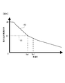
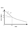
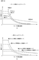
- FIG. 4 is a travel performance diagram showing the relationship between the vehicle speed V and the maximum travel driving force A when the accelerator pedal 9 is depressed to the maximum, that is, when the target engine rotational speed is commanded to the maximum speed.
- the characteristic f0 when the non-restriction mode is set is indicated by a solid line
- the characteristic f1 when the restriction mode is set is indicated by a broken line.
- the traveling performance curve (characteristic f0) shown in FIG. 4 as the vehicle speed V increases, the maximum traveling driving force A (maximum traction force) that can be output decreases.
- the motor displacement qm is held at the minimum value qmin regardless of the magnitude of the traveling load pressure Pt.
- the maximum travel driving force A decreases as compared to the characteristic f0, as indicated by the characteristic f1.
- the maximum traveling driving force is A0 in the characteristic f0
- the maximum traveling driving force is A1 in the characteristic f1 (A1 ⁇ A0).
- the difference between the maximum traveling driving force A of the characteristic f0 and the maximum traveling driving force A of the characteristic f1 corresponds to the limitation amount of the maximum traveling driving force.
- the maximum travel driving force A is limited so that the maximum travel driving force A becomes A1 (constant value) in the range where the vehicle speed V is 0 or more and the threshold Va1 for limit start determination.
- the traveling performance is also shifted from the characteristic f1 to the characteristic f0. Therefore, when the vehicle speed V shifts from the limit mode to the non-limit mode in the range of 0 or more and Va1 or less, the maximum travel driving force that can be output is increased.
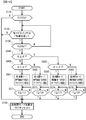
- FIG. 5 is a flowchart showing the processing contents of the driving force limit control by the controller 10 according to the first embodiment.
- the process shown in this flowchart is started, for example, by turning on an ignition switch (not shown), and is repeatedly executed after initialization (not shown) is performed. By default, the unrestricted mode is set.
- the controller 10 repeatedly acquires various information such as information on the vehicle speed detected by the vehicle speed sensor 26 and information on the operation position of the mode switch 23.
- step S110 the controller 10 determines whether the vehicle speed V detected by the vehicle speed sensor 26 is equal to or more than the threshold value Vb1 for determining validity. If an affirmative determination is made in step S110, the process proceeds to step S120, and if a negative determination is made in step S110, the controller 10 sets an invalid mode and proceeds to step S180.
- step S120 the controller 10 determines whether the operation position of the mode switch 23 is a work position. If an affirmative determination is made in step S120, that is, if it is determined that the mode switch 23 is operated to the work position, the controller 10 sets a valid mode and proceeds to step S130. If a negative determination is made in step S120, that is, if it is determined that the mode switch 23 is operated to the travel position, the controller 10 sets the ineffective mode and proceeds to step S180.
- step S130 the controller 10 determines whether the vehicle speed V detected by the vehicle speed sensor 26 is equal to or less than the threshold value Va1 for determination of restriction start.
- the process proceeds to step S160, and when a negative determination is made in step S130, the process returns to step S120.
- step S160 the controller 10 sets the limit mode, starts timer counting, and proceeds to step S170.
- step S170 the controller 10 determines whether the time T measured by the timer is greater than or equal to the time threshold T0. The measurement by the timer is performed until the measurement time T passes a time threshold T0 (fixed value) stored in advance in the storage device of the controller 10. The controller 10 repeatedly executes the process of step S170 until an affirmative determination is made, and proceeds to step S180 when an affirmative determination is made.
- T0 fixed value
- step S180 the controller 10 sets the non-restriction mode, resets the timer, and ends the processing shown in the flowchart of FIG. 5, and the processing from step S110 to step S180 is executed again in the next control cycle. .
- the controller 10 limits the maximum travel driving force for the time threshold T0 after the vehicle speed V decreases to the predetermined threshold value Va1 for restriction start determination or less.
- Va1 for restriction start determination or less.
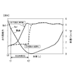
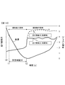
- FIG. 6 is a time chart showing changes in traveling driving force and vehicle speed in the digging operation.
- the behavior of the traveling driving force when the maximum traveling driving force A is limited is shown by a broken line, and the behavior of the traveling driving force when the maximum traveling driving force A is not limited is shown by a solid line.
- the operator operates the mode switch 23 to the work position in advance.
- the operator operates the accelerator pedal 9 and the steering wheel to move the wheel loader forward toward the excavated object such as earth and sand.
- the operator makes the wheel loader rush into the digging object at a vehicle speed V equal to or higher than the threshold value Vb1 for determining the validity (see time point t0).
- the restriction mode is set and travel driving force (traction force) is restricted.
- travel driving force traction force
- Ru travel driving force
- the limitation of the maximum travel driving force A is continued from time t1 when the restriction mode is set to time t2 after the elapse of the time threshold T0 (see time t1 to time t2).
- the operator operates the bucket 112 and the arm 111 while stepping on the accelerator pedal 9 to advance it to generate traveling driving force, excavate earth and sand etc., and load an object into the bucket 112.
- the arm 111 is raised to generate an excavating force, the inertial force by the weight of the wheel loader, and
- the combined force of the combined driving force (horizontal force) and the digging force (vertical force) can be set in the appropriate direction and magnitude. This can improve the excavability.
- the traveling drive force is not limited.
- the maximum traveling driving force A is not limited even if the vehicle speed V falls below Va1.
- the bucket 112 penetrates the object to be excavated, and the traveling drive force increases as the amount of penetration increases (see time t1 to time t2).
- the traveling driving force is greatly increased immediately after the entry into the digging object. If the bucket 112 and the arm 111 are driven while the traveling drive force is high, the load on the work machine becomes excessive, the operation speed of the work machine decreases, the operation of the work machine stops, or the wheel 113 slips. There is a risk of If the operating speed of the working machine decreases or the wheels 113 slip, the working efficiency decreases.
- the wheel loader which concerns on this Embodiment is a working vehicle provided with the traveling drive device which outputs traveling driving force, and a working machine.
- the controller 10 of the wheel loader limits the maximum travel driving force for a predetermined time (T0) after the vehicle speed V detected by the vehicle speed sensor 26 falls below a predetermined threshold value Va1 for determining the start of restriction.
- T0 a predetermined time
- Va1 a predetermined threshold value for determining the start of restriction.
- the limit mode the maximum drive power is limited compared to when the non-limit mode is set, so that the drive power is limited in the process until the work object is sufficiently penetrated into the excavated object. And can prevent the work machine load from becoming excessive.
- the vehicle may not stop after the bucket 112 is plunged into the digging target. If it is decided that the restriction control of the traveling driving force is canceled when the stop of the vehicle is detected, the restriction of the traveling driving force is not canceled during the excavation work, which may lower the working efficiency. There is. On the other hand, in the present embodiment, after the predetermined time (T0) has elapsed, the restriction on the traveling driving force is released, so the state in which the traveling driving force is restricted continues during the digging operation. It is possible to prevent it from
- the valid / invalid mode setting unit 10a of the controller 10 has a maximum for a predetermined time (T0) after the vehicle speed V detected by the vehicle speed sensor 26 falls below the threshold value Va1 for restriction start determination set in advance.
- An invalid mode is set to invalidate the limitation of the traveling driving force A.
- the effective mode or the ineffective mode is set in consideration of the operation position of the mode switch 23. Thus, the operator can set the ineffective mode in which the maximum travel driving force A is not limited according to the work content.
- the controller 10 determines whether the vehicle speed V detected by the vehicle speed sensor 26 is higher than the threshold value Vb1 for validity determination higher than the threshold value Va1 for limitation start determination, and the vehicle speed V is for validity determination
- the maximum travel driving force A is limited for a predetermined period of time (T0) when it is lowered to a limit start determination threshold value Va1 or less from a state higher than the threshold value Vb1.
- T0 a predetermined period of time
- the effective individual condition being equal to or more than the threshold value Vb1 for valid determination higher than the threshold Va1 for limit start determination, hunting of the maximum travel driving force A between the limited value and the non-limit value can be prevented. .
- the wheel loader is provided with a traveling drive device having an HST circuit formed by closed circuit connection of a variable displacement hydraulic pump (HST pump 2) and a variable displacement hydraulic motor (HST motor 3).
- HST pump 2 variable displacement hydraulic pump
- HST motor 3 variable displacement hydraulic motor
- the traveling driving force increases continuously and rapidly according to the decrease in the vehicle speed.
- the combined force of the traveling driving force tends to be excessive. Therefore, according to the present embodiment, the effect obtained by limiting the traveling drive force immediately after the entry into the excavated object is a so-called torque converter drive type in which the engine output is transmitted to the transmission via the torque converter. Appears larger than work vehicles.
- the maximum traveling drive force A is obtained by reducing the displacement qm (motor displacement angle) of the HST motor 3 with reference to the limiting characteristic C1 stored in the storage device of the controller 10.
- the maximum traveling driving force A may be limited by reducing the traveling load pressure Pt (that is, the driving pressure of the HST motor 3).
- the maximum traveling drive force A may be limited by reducing both the displacement volume qm of the HST motor 3 and the traveling load pressure Pt.
- the running load pressure Pt can be adjusted by providing a variable relief valve in the HST circuit and the controller 10 outputting a control signal (excitation current) to the solenoid of the variable relief valve.
- a table (see FIG. 4) of the characteristics of the maximum travel driving force A according to the vehicle speed V is stored in the storage device of the controller 10, and the controller 10 does not exceed the maximum travel driving force A at the detected vehicle speed V
- the displacement qm of the HST motor 3 or the traveling load pressure Pt may be controlled.
- FIGS. 7 and 8 A work vehicle according to a second embodiment will be described with reference to FIGS. 7 and 8.
- the same reference numerals as in the first embodiment denote the same or corresponding parts, and the differences will be mainly described.
- the wheel loader according to the second embodiment has the same configuration as that of the first embodiment (see FIG. 2).
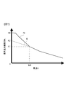
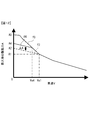
- FIG. 7 is a traveling performance diagram showing the relationship between the vehicle speed V and the maximum traveling driving force A of the work vehicle according to the second embodiment
- FIG. 8 is an excavating of the work vehicle according to the second embodiment It is a time chart which shows change of run driving power and vehicle speed in work.
- the maximum travel driving force A is limited so that the maximum travel driving force A becomes A1 (constant value) in the range where the vehicle speed V is 0 or more and the restriction start determination threshold Va1 or less ((1) See Figure 4).
- the limit control unit 10b of the controller 10 limits the maximum travel driving force A according to the characteristic f2 shown in FIG.
- the limitation of the maximum travel driving force A can be realized by reducing one or both of the displacement qm of the HST motor 3 and the pressure of the HST motor 3.
- the restriction control unit 10b linearly increases the maximum travel driving force A as the vehicle speed V decreases in the range where the vehicle speed V is 0 or more and the threshold Va1 for determining the start of restriction. In other words, as the vehicle speed V decreases, the limitation control unit 10b reduces the limitation amount for limiting the maximum travel driving force A as compared to the first embodiment.
- the maximum travel driving force A is A2 which is larger than A1 and smaller than A0 (A0> A2> A1).
- the restriction control unit 10b of the controller 10 causes the maximum traveling driving force to increase the maximum traveling driving force A as the vehicle speed V detected by the vehicle speed sensor 26 decreases.
- the inertia force of the wheel loader decreases as the vehicle speed V decreases.
- the combined force of the inertia force and the travel driving force by the weight of the vehicle is further added.
- the balance of digging force can be optimized.
- FIG. 9 is a travel performance diagram showing the relationship between the vehicle speed V and the maximum travel driving force A of the work vehicle according to a modification of the second embodiment.
- the maximum travel driving force A increases linearly as the vehicle speed V decreases in the range where the vehicle speed V is 0 or more and the threshold Va1 for determining the start of restriction.
- the modification of the second embodiment in the range where the vehicle speed V is 0 or more and the threshold Va1 for determining the start of restriction, the maximum travel in a step-like (stepwise) manner as the vehicle speed V decreases.
- the driving force A increases.
- the modification of the second embodiment the same function and effect as those of the second embodiment can be obtained.
- FIG. 10 is a time chart showing changes in travel driving force and vehicle speed in the excavation work of the work vehicle according to the third embodiment.
- the broken line shown in FIG. 10 has shown the behavior of the traveling drive force of the working vehicle of 2nd Embodiment.
- a workload pressure sensor 25 is connected to the controller 10.
- the work load pressure sensor 25 detects the discharge pressure (work load pressure) of the work hydraulic pump 4 and outputs a detection signal to the controller 10.
- the wheel loader limits the maximum travel driving force A when the load pressure of the working hydraulic circuit HC2 detected by the work load pressure sensor 25 exceeds a predetermined pressure threshold.
- the traveling drive is performed not only in the digging entry period from when the wheel loader rushes into the excavated object such as earth and sand to start the operation of the working machine but also in the digging operation period after starting the operation of the working machine It is possible to suppress the force from becoming too high, and to optimize the balance between the driving force and the digging force. As a result, the work efficiency of the entire digging operation can be improved.
- FIGS. 11 to 13 A work vehicle according to a fourth embodiment will be described with reference to FIGS. 11 to 13.
- the wheel loader according to the fourth embodiment has the same configuration as that of the second embodiment (see FIG. 2).
- an inclination angle sensor 27 is connected to the controller 10.
- the tilt angle sensor 27 is, for example, a known pendulum-type ground angle sensor, detects a tilt angle ⁇ of the wheel loader, and outputs a detection signal to the controller 10.
- the limit control unit 10b of the controller 10 determines whether the inclination angle ⁇ is equal to or greater than a predetermined angle threshold ⁇ 1.
- FIG. 11 is a view for explaining how the wheel loader digs on a slope.
- the inclination angle ⁇ is an inclination angle from a horizontal surface when the wheel loader is inclined with respect to an axis in the left-right direction, that is, a pitch angle.
- FIG. 12 is a traveling performance diagram showing the relationship between the vehicle speed V and the maximum traveling driving force A of the work vehicle according to the fourth embodiment.
- the maximum travel driving force A gradually increases as the vehicle speed V decreases, and the vehicle speed V is 0
- the maximum travel driving force A is limited so that the maximum travel driving force A becomes A2.
- the restriction control unit 10 b sets the first restriction mode, and the second embodiment has been described.
- the maximum travel driving force A is limited in accordance with the characteristic f2.
- the restriction control unit 10b sets the second restriction mode and restricts the maximum travel driving force A according to the characteristic f4.
- the characteristic f4 is a value obtained by adding a predetermined correction value ⁇ A to the maximum travel driving force A of the characteristic f2 in the range where the vehicle speed V is 0 or more and the restriction start determination threshold Va1 or less as illustrated. .
- the upper limit value of the maximum travel driving force A is determined by the characteristic f0. Therefore, when the value obtained by adding the correction value ⁇ A to the maximum traveling driving force A of the characteristic f2 (maximum traveling driving force A after correction) exceeds the maximum traveling driving force A (upper limit value) determined by the characteristic f0, It is set to this upper limit value.
- the correction value ⁇ A corresponds to the traveling driving force necessary to raise the slope of the inclination angle ⁇ , and is stored in advance in the storage device of the controller 10.
- the range of the vehicle speed V in which the maximum travel driving force A is limited is 0 or more and the range of the restriction start determination threshold Va4 or less.
- the threshold Va4 for determination of restriction start is lower than the threshold Va1 for determination of restriction start (Va4 ⁇ Va1).
- the maximum travel driving force A increases linearly as the vehicle speed V decreases and the maximum travel when the vehicle speed V is 0 when the vehicle speed V is 0 or more and the threshold Va4 for restriction start determination or less.
- the characteristic is that the driving force A is A4.
- the magnitude relationship between A0, A4 and A2 is A0> A4> A2.
- FIG. 13 is a flowchart showing the processing content of the driving force limit control by the controller 10 according to the fourth embodiment.
- the process shown in the flowchart of FIG. 13 is started by turning on the ignition switch, and after the initial setting (not shown) is performed, the processes after step S110 are repeatedly performed for each predetermined control cycle.
- the controller 10 repeatedly acquires various information such as information on the vehicle speed detected by the vehicle speed sensor 26, information on the operation position of the mode switch 23, and information on the inclination angle detected by the inclination angle sensor 27. ing.
- step S130 determines the vehicle speed V is equal to or less than the threshold value Va1 for determination of restriction start by the controller 10. If it is determined in step S130 that the vehicle speed V is equal to or less than the threshold value Va1 for determination of restriction start by the controller 10, the process proceeds to step S440.
- step S440 the controller 10 determines the inclination angle ⁇ detected by the inclination angle sensor 27. It is determined whether or not the angle threshold ⁇ 1 or more. When a negative determination is made in step S440, the process proceeds to step S460, and when an affirmative determination is made in step S440, the process proceeds to step S465.
- step S460 the controller 10 sets the first limit mode, starts timer counting, and proceeds to step S170.
- the traveling drive force is limited in accordance with the characteristic f2.
- step S465 the controller 10 sets the second limit mode, starts timer counting, and proceeds to step S170.
- the traveling drive force is limited according to the characteristic f4 having a smaller limit amount than the characteristic f2.
- time limit of traveling driving force is the same in the case of the first restriction mode and the second restriction mode (see step S170).
- the controller 10 sets the maximum traveling driving force A to be limited based on the tilt angle ⁇ of the wheel loader detected by the tilt angle sensor 27. In this way, it is possible to prevent the travel driving force from being excessively reduced when excavating work on a slope, and to optimize the balance between the combined force of the inertia force and the travel driving force and the excavating force.
- FIG. 14A is a diagram showing the characteristic of the correction value ⁇ A which increases as the inclination angle ⁇ in the work vehicle according to the first modification of the fourth embodiment.
- the correction value ⁇ A is a constant value.
- the correction value ⁇ A changes in accordance with the inclination angle ⁇ .
- the characteristics of the correction value ⁇ A which increases linearly in proportion to the increase of the inclination angle ⁇ are stored in the form of a look-up table.
- the restriction control unit 10b calculates the correction value ⁇ A based on the inclination angle ⁇ detected by the inclination angle sensor 27 with reference to the table of the characteristics of the correction value ⁇ A shown in FIG. 14A.
- the limit control unit 10b adds the correction value ⁇ A to the maximum traveling driving force A set based on the characteristic f2 to obtain the corrected maximum traveling driving force A.
- the maximum travel driving force A after correction is set to the upper limit value when it exceeds the maximum travel driving force A (upper limit value) determined by the characteristic f0.
- the travel driving force can be more appropriately restricted according to the inclination angle ⁇ .
- Va1 may be selected as the threshold for the restriction start determination
- Va4 may be selected as the threshold for the restriction start determination.
- threshold value selection processing for determination of restriction start is executed, and thereafter, similarly to step S130, it is determined whether the vehicle speed V is equal to or less than the threshold (Va1 or Va4).
- the restriction control unit 10b sets the first restriction mode when the inclination angle ⁇ is less than the angle threshold ⁇ 1 and the vehicle speed V is equal to or less than the threshold Va1 for determining the start of restriction.
- the restriction control unit 10b sets the second restriction mode.
- the maximum travel driving force A is limited in accordance with the predetermined characteristic f4.
- the vehicle speed (Va4) at which the restriction of the traveling driving force is started when the inclination angle ⁇ is the angle threshold ⁇ 1 or more is the restriction of the traveling driving force when the inclination angle ⁇ is less than the angle threshold ⁇ 1.
- An example is described in which the vehicle speed is smaller than the vehicle speed (Va1) at which the vehicle is started.
- the characteristic f4B may be set such that the vehicle speed at which the limitation is started becomes Va1 regardless of the inclination angle ⁇ .
- the characteristic f4B is a characteristic in which the maximum travel driving force A linearly increases from A1 to A4 as the vehicle speed V decreases in the range where the vehicle speed V is 0 or more and the threshold Va1 for determining the start of restriction.
- the controller 10 can set the maximum travel driving force A to be limited based on the inclination angle ⁇ of the vehicle detected by the inclination angle sensor 27.
- A4 is a maximum traveling driving force smaller than A0 and larger than A2.
- the time (T0) in which the restriction of the traveling driving force is continued is the same in the case where the first restriction mode is set and the case where the second restriction mode is set.
- the present invention is not limited thereto.
- T0B when the second limit mode is set may be shorter than the threshold T0A (T0B ⁇ T0A).
- FIGS. 15 and 16 A work vehicle according to the fifth embodiment will be described with reference to FIGS. 15 and 16.
- the same reference numerals as in the fourth embodiment denote the same or corresponding parts, and the difference will be mainly described.
- the wheel loader according to the fifth embodiment has the same configuration as that of the fourth embodiment (see FIG. 2).
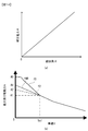
- the restriction control unit 10b of the controller 10 calculates the time change rate (acceleration and deceleration) of the vehicle speed V.
- FIG. 15 is a diagram for explaining the calculation of the temporal change rate ⁇ of the vehicle speed.
- the limit control unit 10b changes the vehicle speed V during a predetermined control cycle based on the vehicle speed V detected in each predetermined control cycle, for example, a difference dv between the vehicle speed V of the current control cycle and the vehicle speed V one control cycle earlier.
- the limitation control unit 10b determines whether the time change rate ⁇ of the vehicle speed is less than a predetermined change rate threshold ⁇ 1. That is, the limit control unit 10b determines whether the deceleration
- the change rate threshold ⁇ 1 is a negative value ( ⁇ 1 ⁇ 0), and is stored in advance in the storage device of the controller 10.
- the limitation control unit 10b sets a first time threshold T1 as the time threshold.
- the limitation control unit 10b sets a second time threshold T2 to the time threshold.
- the heavier and harder the excavated object such as earth and sand, the greater the deceleration of the wheel loader and the shorter the time taken for the wheel loader to stop. Therefore, the magnitude relationship between the first time threshold T1 set when the deceleration is large and the second time threshold T2 set when the deceleration is small is preferably T1 ⁇ T2.
- FIG. 16 is a flowchart showing the processing content of the driving force limit control by the controller 10 according to the fifth embodiment.
- the process shown in the flowchart of FIG. 16 is started by turning on the ignition switch, and after the initial setting (not shown) is performed, the process after step S110 is repeatedly performed for each predetermined control cycle.
- the controller 10 repeatedly acquires various information such as information on the vehicle speed detected by the vehicle speed sensor 26, information on the operation position of the mode switch 23, and information on the inclination angle detected by the inclination angle sensor 27. ing.
- the controller 10 calculates the time change rate ⁇ of the vehicle speed based on the vehicle speed V acquired for each control cycle and the time corresponding to the control cycle, and stores it in the storage device.
- the time change rate ⁇ may be calculated as an average value of several control cycles to several tens of control cycles.
- the flowchart of FIG. 16 deletes steps S460, 465, and 170 of FIG. 13, and between steps S440 and S180, processes of steps S550, 555, 561, 563, 566, 569, 571, 573, 576, and 579. Is added. If the controller 10 determines that the inclination angle ⁇ is less than the angle threshold ⁇ 1 in step S440, the process proceeds to step S550. In step S550, the controller 10 determines whether the time change rate ⁇ of the vehicle speed is less than the change rate threshold ⁇ 1. It is determined whether or not.
- step S550 determines whether the deceleration
- step S561 the controller 10 sets the first limit mode and sets the first time threshold T1 as a time threshold, starts timer counting, and proceeds to step S571.
- step S571 the controller 10 determines whether the time T measured by the timer is equal to or greater than the first time threshold T1. The controller 10 repeatedly executes the process of step S571 until an affirmative determination is made, and proceeds to step S180 when an affirmative determination is made.
- step S563 the controller 10 sets the first limit mode and sets the second time threshold T2 as a time threshold, starts timer counting, and proceeds to step S573.
- step S573 the controller 10 determines whether the time T measured by the timer is equal to or greater than the second time threshold T2. The controller 10 repeatedly executes the process of step S573 until an affirmative determination is made, and proceeds to step S180 when an affirmative determination is made.
- step S440 determines that the controller 10 determines that the inclination angle ⁇ is the angle threshold ⁇ 1 or more
- the process proceeds to step S555, and in step S555, the controller 10 changes the time rate of change ⁇ of the vehicle speed as in step S550. It is determined whether it is less than ⁇ 1. If an affirmative determination is made in step S555, the process proceeds to step S566, and if a negative determination is made in step S555, the process proceeds to step S569.
- step S566 the controller 10 sets the second limit mode and sets the first time threshold T1 as a time threshold, starts timer counting, and proceeds to step S576.
- step S576 the controller 10 determines whether the time T measured by the timer is equal to or greater than the first time threshold T1. The controller 10 repeatedly executes the process of step S576 until an affirmative determination is made, and proceeds to step S180 when an affirmative determination is made.
- step S569 the controller 10 sets the second limit mode and sets the second time threshold T2 as a time threshold, starts timer counting, and proceeds to step S579.
- step S579 the controller 10 determines whether the time T measured by the timer is equal to or greater than the second time threshold T2. The controller 10 repeatedly executes the process of step S579 until an affirmative determination is made, and proceeds to step S180 when an affirmative determination is made.
- the following function and effect can be obtained.
- the time change rate (deceleration) of the vehicle speed of the wheel loader is calculated, and based on the calculated time change rate (deceleration) of the vehicle speed, the time threshold (T1 or T2) for limiting the traveling driving force is set. It was made to do.
- the time limit is as usual, not only from rushing to stopping, but also the subsequent digging work will be limited, and sufficient travel driving force originally required for the digging work will not be obtained, which is a hindrance.
- the -Modification 1 of the fifth embodiment- Limiting control unit 10b determines the travel driving force according to different travel performance characteristics when the time change rate ⁇ of the vehicle speed is less than the change rate threshold ⁇ 1 and when the time change rate ⁇ of the vehicle speed is the change rate threshold ⁇ 1 or more. May be limited. For example, when the time change rate ⁇ of the vehicle speed is less than the change rate threshold ⁇ 1 (when the deceleration is large), the time change rate ⁇ of the vehicle speed is greater than the change rate threshold ⁇ 1 (when the deceleration is small).
- the maximum travel driving force is limited such that the maximum travel driving force is increased, that is, the limitation amount is decreased. Thereby, according to the weight and hardness of excavated objects, such as earth and sand, excavability improvement can be aimed at.
- the restriction set when the time change rate ⁇ of the vehicle speed is greater than or equal to the change rate threshold ⁇ 1 (when the deceleration is small) A vehicle speed threshold for restriction start higher than the vehicle speed threshold for start may be set. Even when the deceleration is large, setting the high vehicle speed threshold can appropriately ensure the effective time of the restriction even when the vehicle speed is sharply reduced, and the excavability can be improved.
- FIGS. 17 and 18 A work vehicle according to the sixth embodiment will be described with reference to FIGS. 17 and 18.
- the same reference numerals as in the first embodiment denote the same or corresponding parts, and the differences will be mainly described.
- travel drive having an HST circuit formed by closed circuit connection of a variable displacement hydraulic pump (HST pump 2) and a variable displacement hydraulic motor (HST motor 3)
- HST pump 2 variable displacement hydraulic pump
- HST motor 3 variable displacement hydraulic motor
- a traveling drive device including an electric motor (FM, RM) for traveling is provided.
- FM, RM electric motor
- the traveling driving force increases continuously and rapidly according to the reduction of the vehicle speed at the time of excavation, so the combined force of the inertia force and the traveling driving force by the vehicle's own weight is excessive. It tends to be For this reason, as in the above-described embodiment, by limiting the traveling drive force, the excavability can be improved.
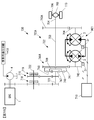
- FIG. 17 is a diagram showing an example of the configuration of a work vehicle according to the sixth embodiment.
- the wheel loader includes a controller 610, an engine 1, an engine control unit 1a, a working hydraulic circuit HC2, and a travel drive device 600D.
- the traveling drive device 600D is configured to include axles 660F and 660R, differential devices 670F and 670R, a propeller shaft 664, and a traveling motor device 600E.
- Traveling electric drive apparatus 600E includes a motor / generator 605, an M / G inverter 625, a front motor 603 having a stator 603s and a rotor 603r, a front inverter 623, a rear motor 604 having a stator 604s and a rotor 604r, and a rear inverter 624.
- a storage element for example, a capacitor
- a converter 627 for example, a converter
- the rotor 603 r of the front motor 603 and the rotor 604 r of the rear motor 604 are connected to each other via a propeller shaft 664 having universal joints 673 and 674 respectively.
- the rotor shaft 665 of the rotor 604r of the rear motor 604 is connected to the first universal joint 674 at one end of the propeller shaft 664, and the rotor shaft 663 of the rotor 603r of the front motor 603 is connected to the second universal joint 673 at the other end of the propeller shaft 664 It is done.
- the rotor 603 r of the front motor 603 and the rotor 604 r of the rear motor 604 are connected by the propeller shaft 664 and the pair of universal joints 673 and 674 and integrally rotate.
- the pair of front wheels (front wheels 113) are connected to the front wheel axle 660F.
- the front wheel axle 660F is connected to the differential device 670F, and the differential device 670F is connected to the rotor shaft 663 of the front motor 603 via a connecting portion 672 consisting of a pair of universal joints.
- the pair of rear wheels (rear wheels 113) are connected to the rear wheel side axle 660R.
- the rear wheel side axle 660R is connected to the differential device 670R, and the differential device 670R is connected to the rotor shaft 665 of the rear motor 604 via a connecting portion 675 consisting of a pair of universal joints.
- the motor / generator 605 is connected to the output shaft of the engine 1 and functions as a generator driven by the engine 1 to generate three-phase AC power.
- the three-phase AC power is converted into DC power by the M / G inverter 625 and supplied to the front inverter 623 and the rear inverter 624.
- the DC power converted by the M / G inverter 625 is also supplied to the storage element 607 via the converter 627, and the storage element 607 is charged.
- the M / G inverter 625, the front inverter 623 and the rear inverter 624 are power converters that convert DC power into AC power or AC power into DC power.
- the M / G inverter 625, the front inverter 623 and the rear inverter 624 are connected to the storage element 607 via the converter 627.
- Converter 627 steps up or down the charge / discharge voltage of storage element 607.
- the storage element 607 is an electric double layer capacitor capable of storing electric power generated by a certain amount of electrical work (for example, several tens of kW, several seconds of work) and discharging the charge stored at a desired time.
- the storage element 607 is charged by DC power converted by the front inverter 623, the rear inverter 624, and the M / G inverter 625.
- the DC power converted by the M / G inverter 625 and / or the DC power output from the storage element 607 is converted by the front inverter 623 and the rear inverter 624 into three-phase AC power.
- the front motor 603 and the rear motor 604 are driven by the three-phase AC power converted by the front inverter 623 and the rear inverter 624, respectively, to generate rotational torque.
- the rotational torque generated by the front motor 603 and the rear motor 604 is transmitted to the front and rear wheels 113 via the differential devices 670F and 670R and the axles 660F and 660R.
- the front motor 603 and the rear motor 604 are rotated by the rotational torque transmitted from the wheel 113 to generate three-phase AC power.
- Three-phase AC power generated by front motor 603 and rear motor 604 is converted to DC power by front inverter 623 and rear inverter 624, respectively, and supplied to storage element 607 through converter 627.
- Storage element 607 is front inverter 623 and It is charged by the DC power converted by the rear inverter 624.
- the controller 610 is configured to include an arithmetic processing unit having a CPU, a ROM and a RAM as storage devices, and other peripheral circuits.
- the controller 610 controls the entire system including the traveling system of the wheel loader and the hydraulic working system, and controls each part so that the entire system exhibits the highest performance.
- the controller 610 receives signals from the forward / reverse switching switch 651, an accelerator pedal sensor 652, a vehicle speed sensor 653, a brake pedal sensor 654, an engine rotational speed sensor 650, and a motor rotational speed sensor 659.
- the forward / reverse switching switch 651 outputs a forward / backward switch signal for commanding forward / reverse of the vehicle to the controller 610.
- the accelerator pedal sensor 652 detects a pedal operation amount of an accelerator pedal (not shown) and outputs an accelerator signal to the controller 610.
- the vehicle speed sensor 653 detects the vehicle traveling speed (vehicle speed) of the wheel loader and outputs a vehicle speed signal to the controller 610.
- the brake pedal sensor 654 detects a pedal operation amount of a brake pedal (not shown) and outputs a brake signal to the controller 610.
- Engine rotational speed sensor 650 detects the actual rotational speed of engine 1 and outputs an actual rotational speed signal to controller 610.
- the motor rotational speed sensor 659 detects the rotational speeds of the front motor 603 and the rear motor 604, and outputs a motor rotational speed signal to the controller 610.
- one of the motor rotational speed sensor 659 and the vehicle speed sensor 653 may be omitted.
- the vehicle speed sensor 653 may be omitted, and the vehicle speed may be calculated based on the motor rotation speed detected by the motor rotation speed sensor 659.
- the controller 610 calculates the required torque according to the vehicle information including the pedal operation amount of the accelerator pedal (not shown), and the front motor 603 and the rear motor 604 output the required torque, the engine 1, the front inverter 623 and the rear The inverter 624 is controlled.
- the controller 610 calculates the amount of power generation required for the front motor 603 and the rear motor 604 based on the required torque.
- the controller 610 calculates a target engine rotational speed for obtaining a predetermined amount of power generation by the motor / generator 605, and outputs an engine drive control signal to the engine control unit 1a based on the calculated target engine rotational speed.
- a drive signal for converting three-phase AC power generated by the generator 605 into DC power is output to the M / G inverter 625.
- the engine control unit 1a compares the actual engine rotational speed Na of the engine 1 detected by the engine rotational speed sensor 650 with the target engine rotational speed Nt from the controller 610 to target the actual engine rotational speed Na of the engine 1
- a fuel injection device (not shown) is controlled to approach the engine rotational speed Nt.
- the controller 610 controls the vehicle operating condition, that is, the vehicle speed information or the accelerator so that the state of charge (SOC: State Of Charge) of the storage element 607 does not fall below a predetermined lower limit and does not exceed a predetermined upper limit.
- the engine 1, the M / G inverter 625, the front inverter 623 and the rear inverter 624, the converter 627, and the like are controlled in accordance with the pedal operation amount of the pedal, the charging rate, and the like.
- the controller 610 calculates a motor request torque which is a torque required for the front motor 603 and the rear motor 604.
- FIG. 18A is a diagram showing a motor request torque map (motor characteristics).
- the motor required torque map is a map that represents a torque curve (characteristic M2) of the front motor 603 and a torque curve (characteristic M1) of the rear motor 604.
- the front motor 603 and the rear motor 604 have different characteristics.
- the front motor 603 is a high-speed motor (characteristic M2) that can not output a large torque at low speed but can drive up to a high speed, and the rear motor 604 can not output torque up to a high speed.
- This is a low speed motor (characteristic M1) capable of delivering a large torque at a low speed range.
- the front motor 603 and the rear motor 604 have different operation areas that can be driven with high efficiency, so high-efficiency motor driving can be performed in a wide range of power performance required for the vehicle.
- Each of characteristic M1 and characteristic M2 is set so that the motor request torque is in inverse proportion to the rotational speed of rear motor 604 and front motor 603 in proportion to the acceleration signal, and is stored in the storage device in controller 610. .
- the controller 610 has a relationship between the acceleration signal and the output of the front motor 603 and the rear motor 604 so that the outputs of the front motor 603 and the rear motor 604 increase and decrease according to the increase and decrease of the accelerator signal input from the accelerator pedal sensor 652. It is set.
- the controller 610 determines a torque curve according to the accelerator signal, and refers to the torque curve at that time to determine the motor request torque by referring to the rotational speeds of the front motor 603 and the rear motor 604 at that time.
- the required torque of each of the front motor 603 and the rear motor 604 is determined, and based on this torque, a motor drive signal is generated by a known method, and the motor drive signal is output to the front inverter 623 and the rear inverter 624.
- controller 610 When an accelerator signal, a brake signal, a forward / backward switch signal, the current vehicle travel speed (vehicle speed) and the like corresponding to the operation command are input, controller 610 requests the torque requested from the vehicle based on the information. Calculate The required torque is the sum of the motor required torque of the rear motor 604 and the motor required torque of the front motor 603.
- An efficiency data table of the rear motor 604 and the front motor 603 is stored in the storage device of the controller 610, and based on the efficiency data table, the controller 610 is controlled to obtain the highest motor efficiency with respect to the required torque. Determine distribution.
- the controller 610 performs torque limitation processing based on the restrictions of the hybrid system and the vehicle when outputting as a torque command to the control device (not shown) that each of the rear inverter 624 and the front inverter 623 has. , RM torque command and FM torque command are output.
- the rear inverter 624 and the front inverter 623 supply three-phase AC power to the respective armature windings (stator windings) of the rear motor 604 and the front motor 603 based on the RM torque command and the FM torque command, and the rotor 603r , 604r to rotate the vehicle.
- the controller 610 has the functions as the mode setting unit 10a and the restriction control unit 10b described in the first embodiment, and sets the restriction mode when the restriction condition is satisfied, If the limit condition is not satisfied, the non-limit mode is set.
- FIG. 18B is a diagram showing a maximum torque map, and shows the maximum torque characteristics when the non-limit mode is set, and the maximum torque characteristics M1L and M2L when the limit mode is set. .
- the storage device of the controller 610 stores a table of maximum torque characteristics M1L for torque limitation. When the limit mode is set, for example, even if the accelerator pedal is depressed to the maximum, the motor request torque of the rear motor 604 is limited to the characteristic M1L.
- the storage device of the controller 610 stores a table of maximum torque characteristics M2L for torque limitation.
- the limit mode is set, for example, even if the accelerator pedal is depressed to the maximum, the motor request torque of the front motor 603 is limited by the characteristic M2L.
- the controller 610 determines the required torque of each of the rear motor 604 and the front motor 603 according to the characteristic M1 and the characteristic M2 according to the depression amount of the accelerator pedal (see FIG. 18A). ).
- controller 610 is set to the upper limit value when the required torque of rear motor 604 calculated based on characteristic M1 exceeds the maximum torque (upper limit value) set in characteristic M1L. (See FIG. 18 (b)).
- the controller 610 sets the upper limit of the required torque of the front motor 603 calculated based on the characteristic M2 when the required torque exceeds the maximum torque (upper limit) set in the characteristic M2L. It is set to a value (see FIG. 18B).
- FIG. 19 the same reference numerals as in the first embodiment denote the same or corresponding parts, and the differences will be mainly described.
- FIG. 19 the high pressure selection valve 16, the check valves 11A and 11B, the overload relief valve 13 and the like in the HST circuit are not shown.
- the work vehicle according to the seventh embodiment includes a traveling drive device 730 having a hydro-mechanical transmission (HMT) 703A, a propeller shaft 704, a differential device 705, and an axle 706.
- HMT hydro-mechanical transmission
- FIG. 19 is a view showing a schematic configuration of a work vehicle according to the seventh embodiment.
- the HMT 703A includes an HST circuit (a hydraulic circuit HC1 for traveling) and a mechanical transmission unit 732 and transmits the driving force of the engine 1 to the HST and the mechanical transmission unit 732 in parallel.
- the rotation of the output shaft of the engine 1 is shifted by the HMT 703A.
- the rotation after transmission is transmitted to the wheel 113 via the propeller shaft 704, the differential device 705, and the axle 706, and the wheel loader travels.
- the HMT 703A includes a clutch device 716 having a forward hydraulic clutch (hereinafter referred to as a forward clutch 718) and a reverse hydraulic clutch (hereinafter referred to as a reverse clutch 719).
- the forward clutch 718 and the reverse clutch 719 engage (connect) when the pressure (clutch pressure) of the pressure oil supplied via the transmission control device (not shown) increases, and release (disconnect) when the clutch pressure decreases. ) Do the action.
- the output shaft of the engine 1 is coupled to a clutch shaft 722.
- the forward clutch 718 When the forward clutch 718 is in the engaged state, the reverse clutch 719 is in the released state, and the clutch shaft 722 rotates integrally with the forward clutch 718, causing the wheel loader to travel in the forward direction.
- the reverse clutch 719 When the reverse clutch 719 is in the engaged state, the forward clutch 718 is in the released state, and the clutch shaft 722 rotates integrally with the reverse clutch 719 to cause the wheel loader to travel in the reverse direction.
- the rotational force of the clutch shaft 722 is transmitted to the input shaft 723 via a gear.
- the sun gear 747 of the planetary gear mechanism 740A is fixed to the input shaft 723.
- a plurality of planetary gears 748 mesh with the outer periphery of the sun gear 747.
- Each planetary gear 748 is pivotally supported by a planet carrier 749, and the planet carrier 749 is fixed to an output shaft 750.
- the output shaft 750 is connected to the propeller shaft 704 described above.
- a ring gear 741 is engaged with the outer periphery of the planetary gear group, and a pump input gear 742 is engaged with the outer periphery of the ring gear 741.
- the pump input gear 742 is fixed to the rotating shaft of the traveling hydraulic pump (HST pump 2).
- a hydraulic circuit (HST motor 3) for traveling is connected to the HST pump 2 in a closed circuit.
- a motor output gear 754 is fixed to the rotation shaft of the HST motor 3, and the motor output gear 754 is meshed with a gear 743 A of the output shaft 750.
- the HST pump 2 is a swash plate type or oblique axis type variable displacement hydraulic pump whose displacement volume is changed according to a tilt angle.
- the displacement is controlled by the regulator 2r.
- the regulator 2 r has a tilt cylinder and a forward / reverse switching valve that switches in accordance with a forward / backward switching signal from the controller 710.
- the control pressure is supplied to the tilt cylinder via the forward / reverse switching valve, the displacement is controlled according to the control pressure, and the operating direction of the tilt cylinder is controlled according to the switching of the forward / reverse switching valve.
- the tilt direction of the HST pump 2 is controlled.
- the HST motor 3 is a swash plate type or oblique axis type variable displacement hydraulic motor whose displacement volume is changed according to the tilt angle.
- the controller 710 By outputting a control signal from the controller 710 to the motor regulator 3r (not shown), the displacement (motor capacity) of the HST motor 3 is controlled.
- the controller 710 reduces the displacement as compared with the case where the difference is small when the actual engine rotation speed Na is lower than the target engine rotation speed Nt and the difference is large. Control small.
- the input division type HMT 703A is employed.
- the HST motor 3 connected by a hydraulic circuit and the HST pump 2 connected to the planetary gear mechanism 740A is connected to the output shaft 750 of the transmission at a constant rotation ratio.
- the output torque of the engine 1 is transmitted in parallel to the HST and the mechanical transmission unit 732 via the planetary gear mechanism 740A, and the wheels 113 are driven.
- the displacement volume qm of the HST motor 3 and the traveling load pressure Pt are controlled to limit the maximum traveling driving force A immediately after the entry to the excavating object in the excavation work.
- the same effect as that of the first embodiment can be obtained.
- the input split type HMT 703A (see FIG. 19) has been described as an example, but the present invention is not limited to this.
- an output division type HMT 703B may be adopted.
- the traveling drive device is illustrated, and the hydraulic circuit HC2 for work is not illustrated.
- the output split type HMT 703B the HST motor 3 connected to the planetary gear mechanism 740B and the HST pump 2 connected by a hydraulic circuit are connected to the input shaft 723 of the transmission at a constant rotation ratio.
- the output torque of the engine 1 is transmitted to the HST and the mechanical transmission unit 732 in parallel, and the wheel 113 is driven via the planetary gear mechanism 740B.
- the rotational force of the input shaft 723 is transmitted to the HST via the gear 743B of the input shaft 723 and the pump input gear 742.
- a sun gear 747 of the planetary gear mechanism 740 B is fixed to the input shaft 723.
- a plurality of planetary gears 748 mesh with the outer periphery of the sun gear 747.
- Each planetary gear 748 is pivotally supported by a planet carrier 749, and the planet carrier 749 is fixed to an output shaft 750.
- the output shaft 750 is connected to the propeller shaft 704 described above.
- a ring gear 741 is engaged with the outer periphery of the planetary gear group, and a motor output gear 754 is engaged with the outer periphery of the ring gear 741.
- the motor output gear 754 is fixed to the rotation shaft of the HST motor 3.
- the present invention may be applied to a wheel loader provided with an EMT (Electro-Mechanical Transmission) 703C instead of the HMTs 703A and 703B shown in FIG. 19 and FIG.
- EMT Electro-Mechanical Transmission
- a generator 840 is provided instead of the HST pump 2
- an electric motor 850 is provided instead of the HST motor 3.
- the output torque of the engine 1 is directly transmitted by the generator 840 and the electric motor 850 through the planetary gear mechanism 740 A and mechanical direct transmission by the mechanical transmission unit 732.
- the wheel 113 is driven by transmitting in parallel to the drive torque transmission.
- the output torque of the engine 1 is transmitted in parallel to the electric torque transmission by the generator 840 and the electric motor 850 and to the mechanical direct drive torque transmission by the mechanical transmission unit 732 via the planetary gear mechanism. Then, the wheel 113 may be driven.
- the maximum value of the motor request torque of the electric motor 850 is limited by the controller (not shown), and the balance between the traveling driving force and the digging force can be optimized.
- a time input device 901 may be provided to set an arbitrary time threshold.
- the time input device 901 may be a dial-type input operation device, or may be an input operation device that selects one of a plurality of operation positions (for example, a heavy excavation operation position and a light excavation operation position).
- the limit control unit 10 b of the controller 10 sets a time threshold based on the signal from the time input device 901. Thereby, the operator can arbitrarily set the time threshold according to the weight and hardness of the excavated object such as soil, or the inclination of the ground, and the condition of the road surface.
- a limit input device 902 may be provided to set the characteristic of any maximum travel driving force.
- the restriction input device 902 may be a dial-type input operation device, or may be an input operation device that selects one of a plurality of operation positions (for example, a heavy excavation operation position and a light excavation operation position).
- the limitation control unit 10 b of the controller 10 sets the characteristic of the maximum traveling drive force A based on the signal from the limitation input device 902. Thereby, the operator can optionally set the maximum travel driving force after the restriction according to the weight and hardness of the excavated object such as earth and sand, the inclination of the ground, and the condition of the road surface.
- a vehicle speed threshold input device 903 may be provided to set an arbitrary vehicle speed threshold.
- the vehicle speed threshold input device 903 may be a dial-type input operation device, or may be an input operation device that selects one of a plurality of operation positions (for example, a heavy excavation operation position and a light excavation operation position).
- the limit control unit 10 b of the controller 10 sets a vehicle speed threshold based on a signal from the vehicle speed threshold input device 903. Thereby, the operator can arbitrarily set the vehicle speed threshold according to the weight and hardness of the excavated object such as earth and sand, the inclination of the ground, and the condition of the road surface.
- the controller 10 determines whether the vehicle speed V detected by the vehicle speed sensor 26 is higher than the threshold value Vb1 for determining validity, and the vehicle speed V is higher than the threshold Vb1 for determining validity.
- the example has been described in which the maximum travel driving force is limited for a predetermined time when the state drops below the threshold value Va1 or Va4 for determining the start of limitation, but the present invention is not limited to this.
- the controller 10 may set the effective mode when the vehicle speed V becomes higher than the threshold value Va1 for determination of restriction start. Note that, as described in the first embodiment, when the vehicle speed V becomes higher than the threshold value Vb1 for determining the validity, setting the valid mode allows between the limit control and the non-limit control. It is preferable because hunting can be prevented.
- Mode 5 Although the controller 10 described the example which sets the effective mode / ineffective mode in consideration of the operation position of the mode switch 23 by embodiment mentioned above, this invention is not limited to this.
- the controller 10 may set the valid mode when the valid individual condition 1 is satisfied, and may set the invalid mode when the valid individual condition 1 is not satisfied. In this case, the mode switch 23 can be omitted.
Abstract
The purpose of the invention is to prevent a work machine load from being excessive and to improve the working efficiency of excavation. Provided is a work vehicle comprising a work machine having an arm and a bucket, a vehicle speed detection device that detects the vehicle speed, a travel drive device that outputs a travel drive force that increases in response to a decrease in the vehicle speed during excavation, and a control device that controls the travel drive force by way of the travel drive device, wherein the work vehicle is characterized in that the control device has a limiting control unit that limits the travel drive force during a prescribed time from when the vehicle speed detected by the vehicle speed detection device drops to or below a predetermined first vehicle speed threshold and the vehicle enters the excavation site to when the work machine begins operations.
Description
本発明は、作業車両に関する。
The present invention relates to a work vehicle.
ホイールローダなどの作業車両では、掘削作業の際、走行駆動力が大きすぎると作業機負荷が過大となって作業機速度が低下したり、タイヤがスリップしてしまい、作業効率が悪化する。一方、走行駆動力が小さすぎると土砂等の掘削対象物にバケットが十分に貫入されず、掘削量が低下し、作業効率が悪化する。
In a work vehicle such as a wheel loader, when the traveling driving force is too large at the time of excavating work, the load on the working machine becomes excessive, the speed of the working machine decreases, the tire slips, and the working efficiency deteriorates. On the other hand, if the traveling driving force is too small, the bucket is not sufficiently penetrated into the excavated object such as earth and sand, so that the amount of excavated is reduced and the working efficiency is deteriorated.
特許文献1には、作業用油圧回路の負荷圧が所定値を超えると、油圧モータの押しのけ容積の最大値を、作業用油圧回路の最大負荷圧に対応した最小制限値まで減少させる作業車両の走行制御装置が記載されている。
In Patent Document 1, when the load pressure of the working hydraulic circuit exceeds a predetermined value, the maximum value of the displacement of the hydraulic motor is reduced to the minimum limit value corresponding to the maximum load pressure of the working hydraulic circuit. A travel control device is described.
バケットを土砂等の掘削対象物に突っ込んだ後、アームを駆動して持ち上げる掘削作業においては、作業機の油圧シリンダに対して掘削対象物からの反力が作用し、アームを駆動する前に作業機負荷が過大になってしまう場合がある。このような場合、作業用油圧回路の負荷圧が所定値を超えてから走行駆動力を制限したとしても掘削の作業効率が向上しないおそれがある。
After the bucket is pushed into the object to be excavated such as earth and sand etc., in the digging operation to drive and lift the arm, the reaction force from the object to be excavated acts on the hydraulic cylinder of the working machine and the work is performed before driving the arm The machine load may be excessive. In such a case, even if the travel driving force is limited after the load pressure of the working hydraulic circuit exceeds a predetermined value, there is a possibility that the work efficiency of the excavation will not be improved.
本発明の一態様による作業車両は、アーム及びバケットを有する作業機と、車速を検出する車速検出装置と、掘削時の前記車速の低下に応じて増加する走行駆動力を出力する走行駆動装置と、前記走行駆動装置により前記走行駆動力を制御する制御装置と、を備えた作業車両において、前記制御装置は、前記車速検出装置で検出された車速が予め定めた第1車速閾値以下に低下し掘削対象物へ突入してから前記作業機の動作を開始させるまでの所定時間の間、前記走行駆動力を制限する制限制御部を有することを特徴とする。
A work vehicle according to an aspect of the present invention includes a work machine having an arm and a bucket, a vehicle speed detection device that detects a vehicle speed, and a traveling drive device that outputs traveling driving force that increases as the vehicle speed decreases during excavation. In a work vehicle including a control device that controls the traveling drive force by the traveling drive device, the control device causes the vehicle speed detected by the vehicle speed detection device to fall below a predetermined first vehicle speed threshold. It is characterized by having a restriction | limiting control part which restrict | limits the said driving | running | working drive force during predetermined time until it starts operation | movement of the said working machine after rushing to an excavation object.
本発明によれば、掘削対象物に作業機を十分に貫入させるまでの過程で走行駆動力を制限し、作業機負荷が過大になることを防止し、掘削の作業効率を向上できる。
According to the present invention, it is possible to limit the travel driving force in the process of causing the working machine to sufficiently penetrate the digging object, prevent the working machine load from becoming excessive, and improve the working efficiency of the digging.
以下、図面を参照して、本発明による作業車両の一実施の形態を説明する。
-第1の実施の形態-
図1は、作業車両の一例であるホイールローダの側面図である。ホイールローダは、アーム111、バケット112、および、前側の車輪113(前輪)等を有する前部車体110と、運転室121、機械室122、および、後側の車輪113(後輪)等を有する後部車体120とで構成される。 Hereinafter, an embodiment of a work vehicle according to the present invention will be described with reference to the drawings.
-First embodiment-
FIG. 1 is a side view of a wheel loader which is an example of a work vehicle. The wheel loader has afront vehicle body 110 having an arm 111, a bucket 112, front wheels 113 (front wheels), etc., a cab 121, a machine room 122, rear wheels 113 (rear wheels) etc. The rear vehicle body 120 is configured.
-第1の実施の形態-
図1は、作業車両の一例であるホイールローダの側面図である。ホイールローダは、アーム111、バケット112、および、前側の車輪113(前輪)等を有する前部車体110と、運転室121、機械室122、および、後側の車輪113(後輪)等を有する後部車体120とで構成される。 Hereinafter, an embodiment of a work vehicle according to the present invention will be described with reference to the drawings.
-First embodiment-
FIG. 1 is a side view of a wheel loader which is an example of a work vehicle. The wheel loader has a
アーム111はアームシリンダ117の駆動により上下方向に回動(俯仰動)し、バケット112はバケットシリンダ115の駆動により上下方向に回動(クラウドまたはダンプ)する。前部車体110と後部車体120はセンタピン101により互いに回動自在に連結され、ステアリングシリンダ116の伸縮により後部車体120に対し前部車体110が左右に屈折する。
The arm 111 is rotated (up and down) in the vertical direction by driving the arm cylinder 117, and the bucket 112 is rotated (cloud or dump) in the vertical direction by driving the bucket cylinder 115. The front vehicle body 110 and the rear vehicle body 120 are rotatably connected to each other by the center pin 101, and the expansion and contraction of the steering cylinder 116 bends the front vehicle body 110 to the left and right with respect to the rear vehicle body 120.
作業機(作業装置)は、アーム111およびバケット112と、作業用油圧回路HC2(図2参照)に設けられるアームシリンダ117およびバケットシリンダ115とを含んで構成され、エンジン1により駆動される作業用油圧ポンプ4(図2参照)から吐出される圧油により駆動される。図示しないが、作業用油圧ポンプ4から吐出される圧油は、作業用油圧回路HC2に設けられる制御弁を介して、アームシリンダ117およびバケットシリンダ115へと供給される。運転室121内のアーム操作レバーおよびバケット操作レバーを操作することにより、作業用油圧回路HC2の制御弁が動作し、アームシリンダ117およびバケットシリンダ115へ作動油が適宜分配され、アーム111およびバケット112に所定の動作を行わせることができる。
The working machine (working device) includes an arm 111 and a bucket 112, and an arm cylinder 117 and a bucket cylinder 115 provided in the working hydraulic circuit HC2 (see FIG. 2), and is for working driven by the engine 1 It is driven by pressure oil discharged from the hydraulic pump 4 (see FIG. 2). Although not shown, pressure oil discharged from the working hydraulic pump 4 is supplied to the arm cylinder 117 and the bucket cylinder 115 via a control valve provided in the working hydraulic circuit HC2. By operating the arm control lever and the bucket control lever in the driver's cab 121, the control valve of the working hydraulic circuit HC2 operates, and the working oil is appropriately distributed to the arm cylinder 117 and the bucket cylinder 115, and the arm 111 and the bucket 112 Can perform predetermined operations.
図2は、第1の実施の形態に係るホイールローダの概略構成を示す図である。ホイールローダは、走行駆動力を出力する走行駆動装置を備えている。走行駆動装置は、走行用油圧回路HC1および動力伝達機構(不図示)を備えている。走行用油圧回路HC1は、エンジン1によって駆動される可変容量形の油圧ポンプ(以下、HSTポンプ2と記す)と、可変容量形の油圧モータ(以下、HSTモータ3と記す)とが、一対の主管路LA,LBによって閉回路接続されたHST(Hydro Static Transmission)回路により構成されている。HSTモータ3の回転は、トランスミッション(不図示)によって変速され、変速後の回転はプロペラシャフト(不図示)、アクスル(不図示)などの動力伝達機構を介して車輪113に伝達され、車輪113が回転することでホイールローダが走行する。
FIG. 2 is a view showing a schematic configuration of the wheel loader according to the first embodiment. The wheel loader includes a traveling drive device that outputs traveling driving force. The traveling drive device includes a traveling hydraulic circuit HC1 and a power transmission mechanism (not shown). The traveling hydraulic circuit HC1 is a pair of a variable displacement hydraulic pump (hereinafter referred to as HST pump 2) driven by the engine 1 and a variable displacement hydraulic motor (hereinafter referred to as HST motor 3). It is comprised by the HST (Hydro Static Transmission) circuit closed-circuit connected by main pipe line LA, LB. The rotation of the HST motor 3 is shifted by a transmission (not shown), and the rotation after the shift is transmitted to the wheel 113 via a power transmission mechanism such as a propeller shaft (not shown) or an axle (not shown). The wheel loader travels by rotating.
エンジン1により駆動されるチャージポンプ5から吐出される圧油は、前後進切換弁6を介して傾転シリンダ8に導かれる。前後進切換弁6は操作レバー6aにより操作され、図示のように前後進切換弁6が中立位置のときは、チャージポンプ5から吐出された圧油は絞り7および前後進切換弁6を介し、傾転シリンダ8の油室8a,8bにそれぞれ作用する。この状態では油室8a,8bに作用する圧力は互いに等しく、ピストン8cは中立位置にある。このため、HSTポンプ2の押しのけ容積qpは0となり、ポンプ吐出量Qは0となる。
The pressure oil discharged from the charge pump 5 driven by the engine 1 is led to the tilt cylinder 8 via the forward / reverse switching valve 6. The forward / backward switching valve 6 is operated by the operation lever 6a, and as shown in the figure, when the forward / backward switching valve 6 is in the neutral position, the pressure oil discharged from the charge pump 5 passes through the throttle 7 and the forward / backward switching valve 6 They act on the oil chambers 8a and 8b of the tilt cylinder 8, respectively. In this state, the pressures acting on the oil chambers 8a and 8b are equal to each other, and the piston 8c is in the neutral position. Therefore, the displacement qp of the HST pump 2 is zero, and the pump discharge amount Q is zero.
前後進切換弁6がA側に切り換えられると、油室8a,8bにはそれぞれ絞り7の上流側圧力と下流側圧力が作用するため、傾転シリンダ8の油室8a,8bに圧力差が生じ、ピストン8cが図示右方向に変位する。これにより、HSTポンプ2のポンプ押しのけ容積qp(ポンプ傾転量)が増加し、HSTポンプ2から吐出された圧油が主管路LAを介してHSTモータ3に導かれ、HSTモータ3が正転し、車両が前進する。前後進切換弁6がB側に切り換えられると、傾転シリンダ8のピストン8cが図示左方向に変位し、HSTポンプ2から吐出された圧油が主管路LBを介してHSTモータ3に導かれ、HSTモータ3が逆転し、車両が後進する。なお、ポンプ押しのけ容積qpは、絞り7の前後差圧ΔPが所定値ΔP0以上になると増加し始め、前後差圧ΔPが大きいほど大きくなる。
When the forward / reverse switching valve 6 is switched to the A side, the upstream pressure and the downstream pressure of the throttle 7 act on the oil chambers 8a and 8b respectively, so a pressure difference occurs in the oil chambers 8a and 8b of the tilting cylinder 8. As a result, the piston 8c is displaced in the right direction in the drawing. As a result, the pump displacement volume qp (pump displacement amount) of the HST pump 2 increases, and the pressure oil discharged from the HST pump 2 is guided to the HST motor 3 via the main line LA, and the HST motor 3 rotates forward. And the vehicle moves forward. When the forward / reverse switching valve 6 is switched to the B side, the piston 8c of the tilting cylinder 8 is displaced in the left direction in the figure, and the pressure oil discharged from the HST pump 2 is guided to the HST motor 3 via the main line LB. , HST motor 3 reversely rotates, and the vehicle reverses. The pump displacement volume qp starts to increase when the differential pressure ΔP across the throttle 7 becomes a predetermined value ΔP0 or more, and increases as the differential pressure ΔP increases.
アクセルペダル9には、アクセルペダル9の操作量を検出する操作量検出器9aが設けられ、操作量検出器9aからの信号はコントローラ10に入力される。コントローラ10は、操作量検出器9aで検出された操作量に基づいて目標エンジン回転速度Ntを演算し、エンジン制御部1aに目標エンジン回転速度Ntに相当する信号を出力する。エンジン制御部1aは、エンジン回転速度センサ1bで検出された実エンジン回転速度Naと、コントローラ10からの目標エンジン回転速度Ntとを比較して、実エンジン回転速度Naを目標エンジン回転速度Ntに近づけるために燃料噴射装置(不図示)を制御する。
The accelerator pedal 9 is provided with an operation amount detector 9a for detecting the amount of operation of the accelerator pedal 9, and a signal from the operation amount detector 9a is input to the controller 10. The controller 10 calculates a target engine rotation speed Nt based on the operation amount detected by the operation amount detector 9a, and outputs a signal corresponding to the target engine rotation speed Nt to the engine control unit 1a. The engine control unit 1a compares the actual engine rotational speed Na detected by the engine rotational speed sensor 1b with the target engine rotational speed Nt from the controller 10, and brings the actual engine rotational speed Na closer to the target engine rotational speed Nt. Control the fuel injection system (not shown).
チャージポンプ5から吐出された圧油の流量(吐出量)は、エンジン回転速度に比例し、絞り7の前後差圧ΔPはエンジン回転速度に比例する。このため、ポンプ押しのけ容積qpもエンジン回転速度に比例する。チャージポンプ5から吐出された圧油は、絞り7およびチェック弁11A,11Bを通過して主管路LA,LBに導かれ、HST回路(HC1)に補充される。絞り7の下流側圧力はチャージリリーフ弁12により制限され、主管路LA,LBの最高圧力はオーバーロードリリーフ弁13により制限される。
The flow rate (discharge amount) of the pressure oil discharged from the charge pump 5 is proportional to the engine rotation speed, and the differential pressure ΔP of the throttle 7 is proportional to the engine rotation speed. Therefore, the pump displacement qp is also proportional to the engine rotational speed. The pressure oil discharged from the charge pump 5 passes through the throttle 7 and the check valves 11A and 11B, is led to the main lines LA and LB, and is replenished to the HST circuit (HC1). The pressure on the downstream side of the throttle 7 is limited by the charge relief valve 12, and the maximum pressure of the main lines LA, LB is limited by the overload relief valve 13.
HSTモータ3の押しのけ容積qm(モータ傾転角)はレギュレータ14により制御される。レギュレータ14は電磁切換弁や電磁比例弁等を含む電気式レギュレータである。信号ライン14aを介して出力されるコントローラ10からの制御電流によりレギュレータ14を駆動することで、傾転制御レバー140を駆動し、押しのけ容積qmを変更する。モータ傾転制御部にはストッパ15が設けられ、傾転制御レバー140がストッパ15に当接し、モータ押しのけ容積qmの最小値が所定値qminに機械的に制限される。なお、レギュレータ14の非通電時には、ストッパ15に傾転制御レバー140が当接してモータ押しのけ容積qmは最小値qminに保持される。レギュレータ14に出力される制御電流が増加すると、モータ押しのけ容積qmが増加する。
The displacement volume qm (motor displacement angle) of the HST motor 3 is controlled by the regulator 14. The regulator 14 is an electric regulator including an electromagnetic switching valve, an electromagnetic proportional valve, and the like. By driving the regulator 14 with the control current from the controller 10 output via the signal line 14a, the displacement control lever 140 is driven to change the displacement volume qm. A stopper 15 is provided in the motor displacement control unit, the displacement control lever 140 abuts on the stopper 15, and the minimum value of the motor displacement volume qm is mechanically limited to a predetermined value qmin. When the regulator 14 is not energized, the tilt control lever 140 abuts on the stopper 15 to hold the motor displacement qm at the minimum value qmin. When the control current output to the regulator 14 increases, the motor displacement qm increases.
コントローラ10は、CPU,ROM,RAM,その他の周辺回路などを有する演算処理装置を含んで構成される。コントローラ10は、有効/無効モード設定部10aと制限制御部10bを機能的に有している。
The controller 10 is configured to include an arithmetic processing unit having a CPU, a ROM, a RAM, other peripheral circuits, and the like. The controller 10 functionally includes a valid / invalid mode setting unit 10a and a limit control unit 10b.
コントローラ10には、車速センサ26が接続されている。車速センサ26は、車両の走行速度(車速)Vに相当する情報を検出し、検出信号をコントローラ10に出力する。車速センサ26は、たとえば、HSTモータ3に接続されるトランスミッション(不図示)の出力軸の回転速度を検出する回転速度検出装置により構成できる。
A vehicle speed sensor 26 is connected to the controller 10. The vehicle speed sensor 26 detects information corresponding to the traveling speed (vehicle speed) V of the vehicle, and outputs a detection signal to the controller 10. The vehicle speed sensor 26 can be configured, for example, by a rotational speed detection device that detects the rotational speed of the output shaft of a transmission (not shown) connected to the HST motor 3.
コントローラ10には、高圧選択弁16で選択された高圧側の主管路LA,LBの圧力(走行負荷圧Pt)を検出する走行負荷圧センサ21からの信号と、モードスイッチ23からの信号がそれぞれ入力される。モードスイッチ23は、オペレータにより、走行位置および作業位置のいずれかの操作位置が選択されるスイッチであり、選択された操作位置に対応する操作信号をコントローラ10に出力する。
In the controller 10, a signal from the running load pressure sensor 21 for detecting the pressure (running load pressure Pt) of the high pressure side main pipelines LA, LB selected by the high pressure selection valve 16 and a signal from the mode switch 23 are respectively It is input. The mode switch 23 is a switch by which an operating position of either the traveling position or the working position is selected by the operator, and outputs an operation signal corresponding to the selected operating position to the controller 10.
有効/無効モード設定部10aは、以下の有効個別条件1および有効個別条件2が成立しているか否かを判定する。有効/無効モード設定部10aは、有効個別条件1および有効個別条件2のいずれもが満たされた場合、有効条件が成立したと判定し、有効モードを設定する。有効/無効モード設定部10aは、有効個別条件1および有効個別条件2のいずれかが成立していない場合、有効条件は成立していないと判定し、無効モードを設定する。
(有効個別条件1)車速センサ26で検出された車速Vが有効判定用の閾値Vb1以上である
(有効個別条件2)モードスイッチ23が作業位置に操作されている The valid / invalidmode setting unit 10a determines whether or not the following valid individual condition 1 and valid individual condition 2 are satisfied. When both of the valid individual condition 1 and the valid individual condition 2 are satisfied, the valid / invalid mode setting unit 10a determines that the valid condition is satisfied, and sets the valid mode. If either the valid individual condition 1 or the valid individual condition 2 is not satisfied, the valid / invalid mode setting unit 10a determines that the valid condition is not satisfied, and sets the invalid mode.
(Effective Individual Condition 1) The vehicle speed V detected by thevehicle speed sensor 26 is equal to or more than the threshold value Vb1 for effective determination (Effective Individual Condition 2) The mode switch 23 is operated to the work position
(有効個別条件1)車速センサ26で検出された車速Vが有効判定用の閾値Vb1以上である
(有効個別条件2)モードスイッチ23が作業位置に操作されている The valid / invalid
(Effective Individual Condition 1) The vehicle speed V detected by the
制限制御部10bは、走行負荷圧センサ21で検出された走行負荷圧Ptに応じてモータ押しのけ容積qmを制御する。図3は、走行負荷圧Ptとモータ押しのけ容積qmの関係を示す図である。コントローラ10の記憶装置には、非制限特性C0と、制限特性C1がルックアップテーブル形式で記憶されている。非制限特性C0は、走行負荷圧Ptが所定値Pt0未満のとき、モータ押しのけ容積qmが最小値qminとなる特性である。非制限特性C0は、走行負荷圧Ptが所定値Pt0から所定値Pt1にかけて上昇することに応じて、モータ押しのけ容積が最小値qminから最大値qmaxまで直線的に増加し、走行負荷圧Ptが所定値Pt1よりも大きくなるとモータ押しのけ容積が最大値qmaxとなる特性である。
The limit control unit 10 b controls the motor displacement qm in accordance with the traveling load pressure Pt detected by the traveling load pressure sensor 21. FIG. 3 is a diagram showing the relationship between the traveling load pressure Pt and the motor displacement qm. The storage device of the controller 10 stores the non-limiting characteristic C0 and the limiting characteristic C1 in the form of a look-up table. The non-limitation characteristic C0 is a characteristic in which the motor displacement volume qm is a minimum value qmin when the traveling load pressure Pt is less than a predetermined value Pt0. In the non-limiting characteristic C0, the motor displacement volume increases linearly from the minimum value qmin to the maximum value qmax in response to the traveling load pressure Pt rising from the predetermined value Pt0 to the predetermined value Pt1, and the traveling load pressure Pt is predetermined. When the value is larger than the value Pt1, the motor displacement is the maximum value qmax.
制限特性C1は、走行負荷圧Ptにかかわらず、モータ押しのけ容積qmが最小値qminとなる特性である。
The limiting characteristic C1 is a characteristic in which the motor displacement qm is a minimum value qmin regardless of the traveling load pressure Pt.
制限制御部10bは、以下の制限個別条件1および制限個別条件2が成立しているか否かを判定する。制限制御部10bは、制限個別条件1および制限個別条件2のいずれもが満たされた場合、制限条件が成立したと判定し、制限モードを設定する。制限制御部10bは、制限個別条件1および制限個別条件2のいずれかが成立していない場合、制限条件は成立していないと判定し、非制限モードを設定する。
(制限個別条件1)有効モードが設定されている
(制限個別条件2)車速センサ26で検出された車速Vが制限開始判定用の閾値Va1以下である Therestriction control unit 10b determines whether the following restriction individual condition 1 and restriction individual condition 2 are satisfied. When both of the restriction individual condition 1 and the restriction individual condition 2 are satisfied, the restriction control unit 10 b determines that the restriction condition is satisfied, and sets the restriction mode. When either of the restriction individual condition 1 and the restriction individual condition 2 is not satisfied, the restriction control unit 10 b determines that the restriction condition is not satisfied, and sets the non-restriction mode.
(Restriction Individual Condition 1) The effective mode is set (Restriction Individual Condition 2) The vehicle speed V detected by thevehicle speed sensor 26 is equal to or less than the threshold Va1 for determination of restriction start
(制限個別条件1)有効モードが設定されている
(制限個別条件2)車速センサ26で検出された車速Vが制限開始判定用の閾値Va1以下である The
(Restriction Individual Condition 1) The effective mode is set (Restriction Individual Condition 2) The vehicle speed V detected by the
制限開始判定用の閾値Va1は、土砂等の掘削対象物へバケット112を突入させた直後の車速に相当し、予め実験等に基づき決定される。制限開始判定用の閾値Va1には、たとえば、4km/h程度の値が、予めコントローラ10の記憶装置に記憶されている。なお、上述した有効判定用の閾値Vb1は、制限開始判定用の閾値Va1よりも高い車速であり(Vb1>Va1)、後述する最大走行駆動力Aが制限値と非制限値との間でハンチングすることを防止するために予め実験等に基づき決定される。有効判定用の閾値Vb1には、たとえば、5km/h程度の値が、予めコントローラ10の記憶装置に記憶されている。
The threshold value Va1 for determining the start of restriction corresponds to the vehicle speed immediately after the bucket 112 is plunged into the excavated object such as earth and sand, and is determined in advance based on experiments and the like. For example, a value of about 4 km / h is stored in advance in the storage device of the controller 10 as the threshold value Va1 for determining the start of restriction. Note that the threshold value Vb1 for determination of validity described above is a vehicle speed higher than the threshold value Va1 for determination of restriction start (Vb1> Va1), and the maximum travel driving force A described later is hunting between the limit value and the non limit value. It is determined in advance based on an experiment etc. in order to prevent doing. For example, a value of about 5 km / h is stored in advance in the storage device of the controller 10 as the threshold value Vb1 for determining validity.
非制限モードが設定されると、制限制御部10bは、非制限特性C0のテーブルを参照し、走行負荷圧センサ21で検出された走行負荷圧Ptに基づいて、モータ押しのけ容積qmを演算する。
When the non-limiting mode is set, the limitation control unit 10b refers to the table of the non-limiting characteristic C0 and calculates the motor displacement qm based on the traveling load pressure Pt detected by the traveling load pressure sensor 21.
制限モードが設定されると、制限制御部10bは、制限特性C1に基づいて、モータ押しのけ容積qmを制御する。本実施の形態では、制限特性C1は一定値(最小値qmin)であるので、制限モードが設定されている間は、走行負荷圧Ptにかかわらず、モータ押しのけ容積qmが最小値qminに設定される。
When the limit mode is set, the limit control unit 10b controls the motor displacement qm based on the limit characteristic C1. In the present embodiment, since limit characteristic C1 is a constant value (minimum value qmin), motor displacement volume qm is set to minimum value qmin while the limit mode is set, regardless of traveling load pressure Pt. Ru.
制限制御部10bは、制限モードを時間閾値T0だけ維持する。時間閾値T0は、予めコントローラ10の記憶装置に記憶されている。時間閾値T0は、車速Vが制限開始判定用の閾値Va1から0となる(停止する)まで、すなわちホイールローダが土砂等の掘削対象物へ突入してから作業機の動作を開始させるまでの時間に相当し、実験等により予め任意の時間が設定されている。時間閾値T0には、たとえば、0.4秒程度の値が設定される。
The limit control unit 10b maintains the limit mode for the time threshold T0. The time threshold T0 is stored in advance in the storage device of the controller 10. The time threshold T0 is from the threshold value Va1 for determining the start of restriction to 0 (stops) from the threshold value Va1 for determination of restriction start, that is, the time from when the wheel loader rushes into a digging object such as earth and sand to start the operation of the working machine And an arbitrary time is set in advance by experiment or the like. For example, a value of about 0.4 seconds is set as the time threshold T0.
制限制御部10bは、制限モードが設定されると、内蔵するタイマにより時間の計測を開始する。タイマによる計測時間Tが時間閾値T0以上になると、すなわち制限モードが設定されてから所定時間(T0)が経過すると、制限制御部10bは制限モードから非制限モードにモードを切り換え、走行駆動力の制限制御を解除する。
When the limit mode is set, the limit control unit 10b starts measuring time by the built-in timer. When the measurement time T by the timer becomes equal to or more than the time threshold T0, that is, when a predetermined time (T0) elapses after the restriction mode is set, the restriction control unit 10b switches the mode from the restriction mode to the non-restriction mode, Release restriction control.
走行負荷圧Ptとモータ押しのけ容積qmとの積は、HSTモータ3の出力トルクに相当する。HSTモータ3の回転速度は、「ポンプの吐出量Q×モータ容積効率/モータ押しのけ容積qm」で表される。車両の走行速度(車速)は、モータ回転速度に比例する。したがって、走行負荷圧Ptが大きくモータ押しのけ容積qmが大きいと、車両は低速高トルクで走行することができ、走行負荷圧Ptが小さくモータ押しのけ容積qmが小さいと、車両は高速低トルクで走行することができる。
The product of the traveling load pressure Pt and the motor displacement volume qm corresponds to the output torque of the HST motor 3. The rotational speed of the HST motor 3 is expressed by “pump displacement Q × motor volume efficiency / motor displacement qm”. The traveling speed (vehicle speed) of the vehicle is proportional to the motor rotational speed. Therefore, when the traveling load pressure Pt is large and the motor displacement volume qm is large, the vehicle can travel at low speed and high torque, and when the traveling load pressure Pt is small and the motor displacement volume qm is small, the vehicle travels at high speed and low torque be able to.
図4は、アクセルペダル9を最大に踏み込み操作したとき、つまり目標エンジン回転速度を最高速度に指令した場合の車速Vと最大走行駆動力Aの関係を示す走行性能線図である。図4では、非制限モードが設定されたときの特性f0を実線で示し、制限モードが設定されたときの特性f1を破線で示している。図4に示す走行性能曲線(特性f0)によれば、車速Vの増加に伴い出力可能な最大走行駆動力A(最大牽引力)が減少する。
FIG. 4 is a travel performance diagram showing the relationship between the vehicle speed V and the maximum travel driving force A when the accelerator pedal 9 is depressed to the maximum, that is, when the target engine rotational speed is commanded to the maximum speed. In FIG. 4, the characteristic f0 when the non-restriction mode is set is indicated by a solid line, and the characteristic f1 when the restriction mode is set is indicated by a broken line. According to the traveling performance curve (characteristic f0) shown in FIG. 4, as the vehicle speed V increases, the maximum traveling driving force A (maximum traction force) that can be output decreases.
制限モードが設定されると、モータ押しのけ容積qmは走行負荷圧Ptの大きさにかかわらず最小値qminに保持される。このようにモータ押しのけ容積qmが最小値qminに保持されると、特性f1に示すように最大走行駆動力Aが特性f0に比べて減少する。たとえば、車速Vが0の場合、特性f0では最大走行駆動力がA0であるのに対し、特性f1では最大走行駆動力がA1である(A1<A0)。なお、特性f0の最大走行駆動力Aと特性f1の最大走行駆動力Aの差は、最大走行駆動力の制限量に相当する。
When the limit mode is set, the motor displacement qm is held at the minimum value qmin regardless of the magnitude of the traveling load pressure Pt. As described above, when the motor displacement volume qm is held at the minimum value qmin, the maximum travel driving force A decreases as compared to the characteristic f0, as indicated by the characteristic f1. For example, when the vehicle speed V is 0, the maximum traveling driving force is A0 in the characteristic f0, whereas the maximum traveling driving force is A1 in the characteristic f1 (A1 <A0). The difference between the maximum traveling driving force A of the characteristic f0 and the maximum traveling driving force A of the characteristic f1 corresponds to the limitation amount of the maximum traveling driving force.
本実施の形態では、車速Vが0以上かつ制限開始判定用の閾値Va1以下の範囲で、最大走行駆動力AがA1(一定値)となるように、最大走行駆動力Aが制限される。制限モードが設定された後、所定時間(T0)が経過し、非制限モードに移行すると、走行性能も特性f1から特性f0に移行する。このため、車速Vが0以上かつVa1以下の範囲で制限モードから非制限モードに移行すると、出力可能な最大走行駆動力が増加することになる。
In the present embodiment, the maximum travel driving force A is limited so that the maximum travel driving force A becomes A1 (constant value) in the range where the vehicle speed V is 0 or more and the threshold Va1 for limit start determination. After the limit mode is set, when the predetermined time (T0) elapses and the mode is shifted to the non-limit mode, the traveling performance is also shifted from the characteristic f1 to the characteristic f0. Therefore, when the vehicle speed V shifts from the limit mode to the non-limit mode in the range of 0 or more and Va1 or less, the maximum travel driving force that can be output is increased.
図5は、第1の実施の形態に係るコントローラ10による駆動力制限制御の処理内容を示すフローチャートである。このフローチャートに示す処理は、たとえば、図示しないイグニッションスイッチのオンにより開始され、図示しない初期設定が行われた後、繰り返し実行される。初期設定では、非制限モードが設定される。なお、図示しないが、コントローラ10は、車速センサ26で検出される車速の情報、モードスイッチ23の操作位置の情報などの各種情報を繰り返し取得している。
FIG. 5 is a flowchart showing the processing contents of the driving force limit control by the controller 10 according to the first embodiment. The process shown in this flowchart is started, for example, by turning on an ignition switch (not shown), and is repeatedly executed after initialization (not shown) is performed. By default, the unrestricted mode is set. Although not shown, the controller 10 repeatedly acquires various information such as information on the vehicle speed detected by the vehicle speed sensor 26 and information on the operation position of the mode switch 23.
ステップS110において、コントローラ10は、車速センサ26で検出された車速Vが有効判定用の閾値Vb1以上であるか否かを判定する。ステップS110で肯定判定されるとステップS120へ進み、ステップS110で否定判定されると、コントローラ10は無効モードを設定してステップS180へ進む。
In step S110, the controller 10 determines whether the vehicle speed V detected by the vehicle speed sensor 26 is equal to or more than the threshold value Vb1 for determining validity. If an affirmative determination is made in step S110, the process proceeds to step S120, and if a negative determination is made in step S110, the controller 10 sets an invalid mode and proceeds to step S180.
ステップS120において、コントローラ10は、モードスイッチ23の操作位置が作業位置であるか否かを判定する。ステップS120で肯定判定、すなわちモードスイッチ23が作業位置に操作されていると判定されると、コントローラ10は有効モードを設定してステップS130へ進む。ステップS120で否定判定、すなわちモードスイッチ23が走行位置に操作されていると判定されると、コントローラ10は無効モードを設定してステップS180へ進む。
In step S120, the controller 10 determines whether the operation position of the mode switch 23 is a work position. If an affirmative determination is made in step S120, that is, if it is determined that the mode switch 23 is operated to the work position, the controller 10 sets a valid mode and proceeds to step S130. If a negative determination is made in step S120, that is, if it is determined that the mode switch 23 is operated to the travel position, the controller 10 sets the ineffective mode and proceeds to step S180.
ステップS130において、コントローラ10は、車速センサ26で検出された車速Vが制限開始判定用の閾値Va1以下であるか否かを判定する。ステップS130で肯定判定されるとステップS160へ進み、ステップS130で否定判定されるとステップS120へ戻る。
In step S130, the controller 10 determines whether the vehicle speed V detected by the vehicle speed sensor 26 is equal to or less than the threshold value Va1 for determination of restriction start. When an affirmative determination is made in step S130, the process proceeds to step S160, and when a negative determination is made in step S130, the process returns to step S120.
ステップS160において、コントローラ10は、制限モードを設定し、タイマのカウントを開始してステップS170へ進む。ステップS170において、コントローラ10は、タイマで計測された時間Tが時間閾値T0以上であるか否かを判定する。タイマによる計測は、計測時間Tが予めコントローラ10の記憶装置に記憶された時間閾値T0(一定値)を経過するまで行われる。コントローラ10は、ステップS170の処理を肯定判定されるまで繰り返し実行し、肯定判定されるとステップS180へ進む。
In step S160, the controller 10 sets the limit mode, starts timer counting, and proceeds to step S170. In step S170, the controller 10 determines whether the time T measured by the timer is greater than or equal to the time threshold T0. The measurement by the timer is performed until the measurement time T passes a time threshold T0 (fixed value) stored in advance in the storage device of the controller 10. The controller 10 repeatedly executes the process of step S170 until an affirmative determination is made, and proceeds to step S180 when an affirmative determination is made.
ステップS180において、コントローラ10は、非制限モードを設定し、タイマをリセットして図5のフローチャートに示す処理を終了し、次の制御周期で、再びステップS110からステップS180までの処理が実行される。
In step S180, the controller 10 sets the non-restriction mode, resets the timer, and ends the processing shown in the flowchart of FIG. 5, and the processing from step S110 to step S180 is executed again in the next control cycle. .
このように、本実施の形態に係るコントローラ10は、車速Vが予め定めた制限開始判定用の閾値Va1以下に低下してから時間閾値T0の間、最大走行駆動力を制限する。これにより、掘削作業において、ホイールローダの自重による慣性力および走行駆動力の合成力と、掘起力(作業機を上昇させる力)とのバランスの適正化を図ることができる。
As described above, the controller 10 according to the present embodiment limits the maximum travel driving force for the time threshold T0 after the vehicle speed V decreases to the predetermined threshold value Va1 for restriction start determination or less. As a result, in the digging operation, it is possible to optimize the balance between the combined force of the inertial force and the traveling driving force by the weight of the wheel loader and the excavating force (force to raise the work machine).
図6は、掘削作業における走行駆動力と車速の変化を示すタイムチャートである。図6において、最大走行駆動力Aを制限した場合の走行駆動力の挙動を破線で示し、最大走行駆動力Aを制限しない場合の走行駆動力の挙動を実線で示している。
FIG. 6 is a time chart showing changes in traveling driving force and vehicle speed in the digging operation. In FIG. 6, the behavior of the traveling driving force when the maximum traveling driving force A is limited is shown by a broken line, and the behavior of the traveling driving force when the maximum traveling driving force A is not limited is shown by a solid line.
走行駆動力を制限する場合について説明する。オペレータは、予めモードスイッチ23を作業位置に操作しておく。オペレータは、アクセルペダル9やステアリングホイールを操作して、ホイールローダを土砂等の掘削対象物に向けて前進走行させる。オペレータは、有効判定用の閾値Vb1以上の車速Vでホイールローダを掘削対象物に突入させる(時点t0参照)。
The case of limiting the traveling driving force will be described. The operator operates the mode switch 23 to the work position in advance. The operator operates the accelerator pedal 9 and the steering wheel to move the wheel loader forward toward the excavated object such as earth and sand. The operator makes the wheel loader rush into the digging object at a vehicle speed V equal to or higher than the threshold value Vb1 for determining the validity (see time point t0).
ホイールローダが掘削対象物に突入し、掘削対象物からの反力により車速Vが減速して制限開始判定用の閾値Va1以下になると、制限モードが設定され、走行駆動力(牽引力)が制限される。最大走行駆動力Aの制限は、制限モードが設定された時点t1から時間閾値T0経過後の時点t2まで継続される(時点t1~時点t2参照)。
When the wheel loader rushes into the object to be excavated and the vehicle speed V decelerates due to the reaction force from the object to be excavated and becomes less than or equal to the threshold Va1 for determination of restriction start, the restriction mode is set and travel driving force (traction force) is restricted. Ru. The limitation of the maximum travel driving force A is continued from time t1 when the restriction mode is set to time t2 after the elapse of the time threshold T0 (see time t1 to time t2).
オペレータは、アクセルペダル9を踏み込みつつ、バケット112およびアーム111を操作して、前進させて走行駆動力を発生させながら土砂等を掘削して、対象物をバケット112に積み込む。本実施の形態によれば、掘削対象物への突入直後から走行駆動力が制限されているので、アーム111を上昇させ、掘起力を発生させたときに、ホイールローダの自重による慣性力および走行駆動力の合成力(水平方向の力)と、掘起力(鉛直方向の力)との合成力を適正な方向、大きさにすることができる。これにより、掘削性を向上することができる。
The operator operates the bucket 112 and the arm 111 while stepping on the accelerator pedal 9 to advance it to generate traveling driving force, excavate earth and sand etc., and load an object into the bucket 112. According to the present embodiment, since the traveling driving force is limited immediately after the entry into the object to be excavated, the arm 111 is raised to generate an excavating force, the inertial force by the weight of the wheel loader, and The combined force of the combined driving force (horizontal force) and the digging force (vertical force) can be set in the appropriate direction and magnitude. This can improve the excavability.
車速Vが制限開始判定用の閾値Va1以下に低下してから時間閾値T0が経過すると、非制限モードが設定され、走行駆動力の制限が解除される。このため、時点t2から走行駆動力が上昇する。
When the time threshold T0 passes after the vehicle speed V falls below the threshold value Va1 for determining the start of restriction, the non-limiting mode is set, and the restriction of the traveling driving force is released. For this reason, traveling driving force rises from time t2.
走行駆動力を制限しない場合を比較例として説明する。たとえば、モードスイッチ23が走行位置に操作されている状態でホイールローダを掘削対象物に突入させた場合、車速VがVa1以下に低下しても最大走行駆動力Aは制限されない。このため、バケット112が掘削対象物に貫入し、貫入量が増加するにつれて走行駆動力が上昇する(時点t1~時点t2参照)。
The case where the traveling drive force is not limited will be described as a comparative example. For example, in the case where the wheel loader is made to dig into the excavating object while the mode switch 23 is operated to the traveling position, the maximum traveling driving force A is not limited even if the vehicle speed V falls below Va1. For this reason, the bucket 112 penetrates the object to be excavated, and the traveling drive force increases as the amount of penetration increases (see time t1 to time t2).
比較例では、本実施の形態に比べて、掘削対象物への突入直後から走行駆動力が大きく上昇する。走行駆動力が高い状態で、バケット112およびアーム111を駆動させると、作業機負荷が過大となり、作業機の動作速度が低下したり、作業機の動作が停止したり、車輪113がスリップしたりしてしまうおそれがある。作業機の動作速度の低下や車輪113のスリップが発生すると、作業効率が低下する。
In the comparative example, compared with the present embodiment, the traveling driving force is greatly increased immediately after the entry into the digging object. If the bucket 112 and the arm 111 are driven while the traveling drive force is high, the load on the work machine becomes excessive, the operation speed of the work machine decreases, the operation of the work machine stops, or the wheel 113 slips. There is a risk of If the operating speed of the working machine decreases or the wheels 113 slip, the working efficiency decreases.
上述した実施の形態によれば、次の作用効果が得られる。
(1)本実施の形態に係るホイールローダは、走行駆動力を出力する走行駆動装置、および作業機を備えた作業車両である。ホイールローダのコントローラ10は、車速センサ26で検出された車速Vが予め定めた制限開始判定用の閾値Va1以下に低下してから所定時間(T0)の間、最大走行駆動力を制限する。制限モードが設定された場合、非制限モードが設定されたときに比べて最大走行駆動力を制限することにより、掘削対象物に作業機を十分に貫入させるまでの過程で走行駆動力を制限し、作業機負荷が過大になることを防止することができる。その結果、掘削突入時における車体の慣性力および走行駆動力の合成力と掘起力とのバランスの適正化を図ることができ、掘削の作業効率を向上することができる。 According to the embodiment described above, the following effects can be obtained.
(1) The wheel loader which concerns on this Embodiment is a working vehicle provided with the traveling drive device which outputs traveling driving force, and a working machine. Thecontroller 10 of the wheel loader limits the maximum travel driving force for a predetermined time (T0) after the vehicle speed V detected by the vehicle speed sensor 26 falls below a predetermined threshold value Va1 for determining the start of restriction. When the limit mode is set, the maximum drive power is limited compared to when the non-limit mode is set, so that the drive power is limited in the process until the work object is sufficiently penetrated into the excavated object. And can prevent the work machine load from becoming excessive. As a result, it is possible to optimize the balance between the combined force of the inertia force of the vehicle body and the traveling drive force at the time of digging and digging and digging force, and to improve the digging work efficiency.
(1)本実施の形態に係るホイールローダは、走行駆動力を出力する走行駆動装置、および作業機を備えた作業車両である。ホイールローダのコントローラ10は、車速センサ26で検出された車速Vが予め定めた制限開始判定用の閾値Va1以下に低下してから所定時間(T0)の間、最大走行駆動力を制限する。制限モードが設定された場合、非制限モードが設定されたときに比べて最大走行駆動力を制限することにより、掘削対象物に作業機を十分に貫入させるまでの過程で走行駆動力を制限し、作業機負荷が過大になることを防止することができる。その結果、掘削突入時における車体の慣性力および走行駆動力の合成力と掘起力とのバランスの適正化を図ることができ、掘削の作業効率を向上することができる。 According to the embodiment described above, the following effects can be obtained.
(1) The wheel loader which concerns on this Embodiment is a working vehicle provided with the traveling drive device which outputs traveling driving force, and a working machine. The
(2)走行駆動力の制限が開始されてから所定時間(T0)が経過した後は、走行駆動力の制限が解除される。このため、登坂走行時などに制限条件が成立し、走行駆動力の制限制御が実行された場合であっても、所定時間(T0(たとえば、0.4秒程度))が経過した後、制限が解除されるので、登坂走行に支障をきたすことはない。
(2) After the predetermined time (T0) has elapsed since the restriction of the traveling driving force was started, the restriction of the traveling driving force is released. For this reason, even when the limiting condition is satisfied when traveling uphill and the like and the limitation control of the traveling driving force is executed, the limitation is performed after a predetermined time (for example, about 0.4 seconds) has elapsed. Will not cause any obstacles to hill climbing.
また、掘削作業では、バケット112を掘削対象物に突入させてから車両が停止しない場合もある。仮に、車両の停止を検出したことをもって走行駆動力の制限制御を解除することとした場合、掘削作業の間、走行駆動力の制限が解除されない状態が継続し、作業効率が低下してしまうおそれがある。これに対して、本実施の形態では、所定時間(T0)を経過した後は、走行駆動力の制限が解除されるので、掘削作業の間、走行駆動力が制限される状態が継続してしまうことを防止できる。
In addition, in the digging operation, the vehicle may not stop after the bucket 112 is plunged into the digging target. If it is decided that the restriction control of the traveling driving force is canceled when the stop of the vehicle is detected, the restriction of the traveling driving force is not canceled during the excavation work, which may lower the working efficiency. There is. On the other hand, in the present embodiment, after the predetermined time (T0) has elapsed, the restriction on the traveling driving force is released, so the state in which the traveling driving force is restricted continues during the digging operation. It is possible to prevent it from
(3)コントローラ10の有効/無効モード設定部10aは、車速センサ26で検出された車速Vが予め定めた制限開始判定用の閾値Va1以下に低下してから所定時間(T0)の間、最大走行駆動力Aを制限することを無効にする無効モードを設定する。本実施の形態では、モードスイッチ23の操作位置を加味して有効モードまたは無効モードが設定される。これにより、オペレータは、作業内容に応じて、最大走行駆動力Aを制限しない無効モードを設定することができる。
(3) The valid / invalid mode setting unit 10a of the controller 10 has a maximum for a predetermined time (T0) after the vehicle speed V detected by the vehicle speed sensor 26 falls below the threshold value Va1 for restriction start determination set in advance. An invalid mode is set to invalidate the limitation of the traveling driving force A. In the present embodiment, the effective mode or the ineffective mode is set in consideration of the operation position of the mode switch 23. Thus, the operator can set the ineffective mode in which the maximum travel driving force A is not limited according to the work content.
(4)コントローラ10は、車速センサ26で検出された車速Vが、制限開始判定用の閾値Va1よりも高い有効判定用の閾値Vb1よりも高いか否かを判定し、車速Vが有効判定用の閾値Vb1よりも高い状態から制限開始判定用の閾値Va1以下に低下した場合に、所定時間(T0)の間、最大走行駆動力Aを制限する。制限開始判定用の閾値Va1よりも高い有効判定用の閾値Vb1以上となることを有効個別条件としたので、最大走行駆動力Aが制限値と非制限値との間でハンチングすることを防止できる。
(4) The controller 10 determines whether the vehicle speed V detected by the vehicle speed sensor 26 is higher than the threshold value Vb1 for validity determination higher than the threshold value Va1 for limitation start determination, and the vehicle speed V is for validity determination The maximum travel driving force A is limited for a predetermined period of time (T0) when it is lowered to a limit start determination threshold value Va1 or less from a state higher than the threshold value Vb1. As the effective individual condition being equal to or more than the threshold value Vb1 for valid determination higher than the threshold Va1 for limit start determination, hunting of the maximum travel driving force A between the limited value and the non-limit value can be prevented. .
(5)ホイールローダは、可変容量形の油圧ポンプ(HSTポンプ2)と可変容量形の油圧モータ(HSTモータ3)とを閉回路接続して形成されたHST回路を有する走行駆動装置を備えている。HST回路を備えるホイールローダでは、掘削作業において、掘削対象物からの反力により車速が低下すると、車速の低下に応じて走行駆動力が連続的かつ速やかに増加し、車両の自重による慣性力と走行駆動力の合成力が過大になりやすい傾向がある。このため、本実施の形態によれば、掘削対象物への突入直後から走行駆動力を制限することで得られる効果が、トルクコンバータを介してエンジン出力をトランスミッションに伝達させる、いわゆるトルコン駆動形式の作業車両に比べて大きく表れる。
(5) The wheel loader is provided with a traveling drive device having an HST circuit formed by closed circuit connection of a variable displacement hydraulic pump (HST pump 2) and a variable displacement hydraulic motor (HST motor 3). There is. In the wheel loader equipped with the HST circuit, when the vehicle speed decreases due to the reaction force from the object to be excavated in the digging operation, the traveling driving force increases continuously and rapidly according to the decrease in the vehicle speed. There is a tendency that the combined force of the traveling driving force tends to be excessive. Therefore, according to the present embodiment, the effect obtained by limiting the traveling drive force immediately after the entry into the excavated object is a so-called torque converter drive type in which the engine output is transmitted to the transmission via the torque converter. Appears larger than work vehicles.
-第1の実施の形態の変形例-
第1の実施の形態では、コントローラ10の記憶装置に記憶されている制限特性C1を参照し、HSTモータ3の押しのけ容積qm(モータ傾転角)を低下させることで、最大走行駆動力Aを制限する例について説明したが、本発明はこれに限定されない。たとえば、走行負荷圧Pt(すなわち、HSTモータ3の駆動圧力)を低下させることで、最大走行駆動力Aを制限してもよい。また、HSTモータ3の押しのけ容積qmおよび走行負荷圧Ptの双方を低下させることで、最大走行駆動力Aを制限してもよい。なお、走行負荷圧Ptは、HST回路に可変リリーフ弁を設け、コントローラ10が可変リリーフ弁のソレノイドに制御信号(励磁電流)を出力することで、調整することができる。 -Modification of the first embodiment-
In the first embodiment, the maximum traveling drive force A is obtained by reducing the displacement qm (motor displacement angle) of theHST motor 3 with reference to the limiting characteristic C1 stored in the storage device of the controller 10. Although a limiting example has been described, the invention is not limited thereto. For example, the maximum traveling driving force A may be limited by reducing the traveling load pressure Pt (that is, the driving pressure of the HST motor 3). In addition, the maximum traveling drive force A may be limited by reducing both the displacement volume qm of the HST motor 3 and the traveling load pressure Pt. The running load pressure Pt can be adjusted by providing a variable relief valve in the HST circuit and the controller 10 outputting a control signal (excitation current) to the solenoid of the variable relief valve.
第1の実施の形態では、コントローラ10の記憶装置に記憶されている制限特性C1を参照し、HSTモータ3の押しのけ容積qm(モータ傾転角)を低下させることで、最大走行駆動力Aを制限する例について説明したが、本発明はこれに限定されない。たとえば、走行負荷圧Pt(すなわち、HSTモータ3の駆動圧力)を低下させることで、最大走行駆動力Aを制限してもよい。また、HSTモータ3の押しのけ容積qmおよび走行負荷圧Ptの双方を低下させることで、最大走行駆動力Aを制限してもよい。なお、走行負荷圧Ptは、HST回路に可変リリーフ弁を設け、コントローラ10が可変リリーフ弁のソレノイドに制御信号(励磁電流)を出力することで、調整することができる。 -Modification of the first embodiment-
In the first embodiment, the maximum traveling drive force A is obtained by reducing the displacement qm (motor displacement angle) of the
コントローラ10の記憶装置に、車速Vに応じた最大走行駆動力Aの特性のテーブル(図4参照)を記憶させておき、コントローラ10が、検出された車速Vにおける最大走行駆動力Aを超えないように、HSTモータ3の押しのけ容積qmや走行負荷圧Ptを制御してもよい。
A table (see FIG. 4) of the characteristics of the maximum travel driving force A according to the vehicle speed V is stored in the storage device of the controller 10, and the controller 10 does not exceed the maximum travel driving force A at the detected vehicle speed V Thus, the displacement qm of the HST motor 3 or the traveling load pressure Pt may be controlled.
-第2の実施の形態-
図7および図8を参照して第2の実施の形態に係る作業車両について説明する。なお、図中、第1の実施の形態と同一もしくは相当部分には同一の参照番号を付し、相違点を主に説明する。第2の実施の形態に係るホイールローダは、第1の実施の形態と同様の構成を有している(図2参照)。 -Second embodiment-
A work vehicle according to a second embodiment will be described with reference to FIGS. 7 and 8. In the figure, the same reference numerals as in the first embodiment denote the same or corresponding parts, and the differences will be mainly described. The wheel loader according to the second embodiment has the same configuration as that of the first embodiment (see FIG. 2).
図7は、第2の実施の形態に係る作業車両の車速Vと最大走行駆動力Aの関係を示す走行性能線図であり、図8は、第2の実施の形態に係る作業車両の掘削作業における走行駆動力と車速の変化を示すタイムチャートである。
FIG. 7 is a traveling performance diagram showing the relationship between the vehicle speed V and the maximum traveling driving force A of the work vehicle according to the second embodiment, and FIG. 8 is an excavating of the work vehicle according to the second embodiment It is a time chart which shows change of run driving power and vehicle speed in work.
第1の実施の形態では、車速Vが0以上かつ制限開始判定用の閾値Va1以下の範囲で、最大走行駆動力AがA1(一定値)となるように最大走行駆動力Aを制限した(図4参照)。これに対して、第2の実施の形態では、コントローラ10の制限制御部10bは、図7に示す特性f2にしたがって、最大走行駆動力Aを制限する。最大走行駆動力Aの制限は、HSTモータ3の押しのけ容積qmおよびHSTモータ3の圧力の一方または双方を低下させることで実現できる。
In the first embodiment, the maximum travel driving force A is limited so that the maximum travel driving force A becomes A1 (constant value) in the range where the vehicle speed V is 0 or more and the restriction start determination threshold Va1 or less ((1) See Figure 4). On the other hand, in the second embodiment, the limit control unit 10b of the controller 10 limits the maximum travel driving force A according to the characteristic f2 shown in FIG. The limitation of the maximum travel driving force A can be realized by reducing one or both of the displacement qm of the HST motor 3 and the pressure of the HST motor 3.
制限制御部10bは、車速Vが0以上かつ制限開始判定用の閾値Va1以下の範囲で、車速Vが低下するにしたがって最大走行駆動力Aが直線的に増加する。換言すれば、制限制御部10bは、車速Vが低下するにしたがって、最大走行駆動力Aを制限する制限量を、第1の実施の形態に比べて小さくする。なお、車速Vが0のとき、最大走行駆動力AはA1よりも大きくA0よりも小さいA2となる(A0>A2>A1)。
The restriction control unit 10b linearly increases the maximum travel driving force A as the vehicle speed V decreases in the range where the vehicle speed V is 0 or more and the threshold Va1 for determining the start of restriction. In other words, as the vehicle speed V decreases, the limitation control unit 10b reduces the limitation amount for limiting the maximum travel driving force A as compared to the first embodiment. When the vehicle speed V is 0, the maximum travel driving force A is A2 which is larger than A1 and smaller than A0 (A0> A2> A1).
このような第2の実施の形態によれば、第1の実施の形態と同様の作用効果に加え、次の作業効果を得ることができる。
(6)制限モードが設定されている場合、コントローラ10の制限制御部10bは、車速センサ26で検出された車速Vが低下するにしたがって最大走行駆動力Aを増加させるように、最大走行駆動力を制限する。ホイールローダの慣性力は、車速Vが低下するほど低下する。このため、図8に示すように、車速Vの低下、すなわち慣性力の低下に応じて最大走行駆動力を徐々に増加させることで、さらに車両の自重による慣性力および走行駆動力の合成力と、掘起力のバランスの適正化を図ることができる。 According to the second embodiment, in addition to the same effects as the first embodiment, the following operation effects can be obtained.
(6) When the restriction mode is set, therestriction control unit 10b of the controller 10 causes the maximum traveling driving force to increase the maximum traveling driving force A as the vehicle speed V detected by the vehicle speed sensor 26 decreases. Limit. The inertia force of the wheel loader decreases as the vehicle speed V decreases. For this reason, as shown in FIG. 8, by gradually increasing the maximum travel driving force according to the decrease of the vehicle speed V, that is, the decrease of the inertia force, the combined force of the inertia force and the travel driving force by the weight of the vehicle is further added. The balance of digging force can be optimized.
(6)制限モードが設定されている場合、コントローラ10の制限制御部10bは、車速センサ26で検出された車速Vが低下するにしたがって最大走行駆動力Aを増加させるように、最大走行駆動力を制限する。ホイールローダの慣性力は、車速Vが低下するほど低下する。このため、図8に示すように、車速Vの低下、すなわち慣性力の低下に応じて最大走行駆動力を徐々に増加させることで、さらに車両の自重による慣性力および走行駆動力の合成力と、掘起力のバランスの適正化を図ることができる。 According to the second embodiment, in addition to the same effects as the first embodiment, the following operation effects can be obtained.
(6) When the restriction mode is set, the
-第2の実施の形態の変形例-
図9を参照して第2の実施の形態の変形例に係る作業車両について説明する。図9は、第2の実施の形態の変形例に係る作業車両の車速Vと最大走行駆動力Aの関係を示す走行性能線図である。第2の実施の形態では、車速Vが0以上かつ制限開始判定用の閾値Va1以下の範囲において、車速Vが低下するにしたがって直線的に最大走行駆動力Aが増加する例について説明した。これに対して、第2の実施の形態の変形例では、車速Vが0以上かつ制限開始判定用の閾値Va1以下の範囲において、車速Vが低下するにしたがってステップ状(階段状)に最大走行駆動力Aが増加する。このような第2の実施の形態の変形例によれば、第2の実施の形態と同様の作用効果を得ることができる。 -Modification of the second embodiment-
A work vehicle according to a modification of the second embodiment will be described with reference to FIG. FIG. 9 is a travel performance diagram showing the relationship between the vehicle speed V and the maximum travel driving force A of the work vehicle according to a modification of the second embodiment. In the second embodiment, an example in which the maximum travel driving force A increases linearly as the vehicle speed V decreases in the range where the vehicle speed V is 0 or more and the threshold Va1 for determining the start of restriction has been described. On the other hand, in the modification of the second embodiment, in the range where the vehicle speed V is 0 or more and the threshold Va1 for determining the start of restriction, the maximum travel in a step-like (stepwise) manner as the vehicle speed V decreases. The driving force A increases. According to the modification of the second embodiment, the same function and effect as those of the second embodiment can be obtained.
-第3の実施の形態-
図10を参照して、第3の実施の形態に係る作業車両について説明する。なお、図中、第2の実施の形態と同一もしくは相当部分には同一の参照番号を付し、相違点を主に説明する。第3の実施の形態に係るホイールローダは、第2の実施の形態と同様の構成を有している(図2参照)。図10は、第3の実施の形態に係る作業車両の掘削作業における走行駆動力と車速の変化を示すタイムチャートである。なお、図10に示す破線は、第2の実施の形態の作業車両の走行駆動力の挙動を示している。 -Third embodiment-
A work vehicle according to the third embodiment will be described with reference to FIG. In the figure, the same reference numerals as in the second embodiment denote the same or corresponding parts, and the differences will be mainly described. The wheel loader according to the third embodiment has the same configuration as that of the second embodiment (see FIG. 2). FIG. 10 is a time chart showing changes in travel driving force and vehicle speed in the excavation work of the work vehicle according to the third embodiment. In addition, the broken line shown in FIG. 10 has shown the behavior of the traveling drive force of the working vehicle of 2nd Embodiment.
図2に示すように、コントローラ10には、作業負荷圧センサ25が接続されている。作業負荷圧センサ25は、作業用油圧ポンプ4の吐出圧(作業負荷圧)を検出し、検出信号をコントローラ10に出力する。
As shown in FIG. 2, a workload pressure sensor 25 is connected to the controller 10. The work load pressure sensor 25 detects the discharge pressure (work load pressure) of the work hydraulic pump 4 and outputs a detection signal to the controller 10.
第3の実施の形態に係るホイールローダは、作業負荷圧センサ25で検出された作業用油圧回路HC2の負荷圧が予め定めた圧力閾値を超えると、最大走行駆動力Aを制限する。これにより、ホイールローダが土砂等の掘削対象物へ突入してから作業機の動作を開始させるまでの掘削進入期間だけでなく、作業機の動作を開始してからの掘削動作期間においても走行駆動力が高くなりすぎることを抑制し、走行駆動力と掘起力のバランスの適正化を図ることができる。この結果、掘削作業全体の作業効率の向上を図ることができる。
The wheel loader according to the third embodiment limits the maximum travel driving force A when the load pressure of the working hydraulic circuit HC2 detected by the work load pressure sensor 25 exceeds a predetermined pressure threshold. Thus, the traveling drive is performed not only in the digging entry period from when the wheel loader rushes into the excavated object such as earth and sand to start the operation of the working machine but also in the digging operation period after starting the operation of the working machine It is possible to suppress the force from becoming too high, and to optimize the balance between the driving force and the digging force. As a result, the work efficiency of the entire digging operation can be improved.
-第4の実施の形態-
図11から図13を参照して第4の実施の形態に係る作業車両について説明する。なお、図中、第2の実施の形態と同一もしくは相当部分には同一の参照番号を付し、相違点を主に説明する。第4の実施の形態に係るホイールローダは、第2の実施の形態と同様の構成を有している(図2参照)。図2に示すように、コントローラ10には、傾斜角センサ27が接続されている。傾斜角センサ27は、たとえば周知の振り子式の対地角センサであり、ホイールローダの傾斜角θを検出し、検出信号をコントローラ10に出力する。 -Fourth embodiment-
A work vehicle according to a fourth embodiment will be described with reference to FIGS. 11 to 13. In the figure, the same reference numerals as in the second embodiment denote the same or corresponding parts, and the differences will be mainly described. The wheel loader according to the fourth embodiment has the same configuration as that of the second embodiment (see FIG. 2). As shown in FIG. 2, aninclination angle sensor 27 is connected to the controller 10. The tilt angle sensor 27 is, for example, a known pendulum-type ground angle sensor, detects a tilt angle θ of the wheel loader, and outputs a detection signal to the controller 10.
図11から図13を参照して第4の実施の形態に係る作業車両について説明する。なお、図中、第2の実施の形態と同一もしくは相当部分には同一の参照番号を付し、相違点を主に説明する。第4の実施の形態に係るホイールローダは、第2の実施の形態と同様の構成を有している(図2参照)。図2に示すように、コントローラ10には、傾斜角センサ27が接続されている。傾斜角センサ27は、たとえば周知の振り子式の対地角センサであり、ホイールローダの傾斜角θを検出し、検出信号をコントローラ10に出力する。 -Fourth embodiment-
A work vehicle according to a fourth embodiment will be described with reference to FIGS. 11 to 13. In the figure, the same reference numerals as in the second embodiment denote the same or corresponding parts, and the differences will be mainly described. The wheel loader according to the fourth embodiment has the same configuration as that of the second embodiment (see FIG. 2). As shown in FIG. 2, an
第4の実施の形態では、コントローラ10の制限制御部10bは、傾斜角θが予め定められた角度閾値θ1以上になったか否かを判定する。図11は、ホイールローダが傾斜地において掘削作業をする様子を説明する図である。なお、傾斜角θとは、ホイールローダが左右方向の軸を中心に傾いたときの水平面からの傾き角度、すなわちピッチ角度である。
In the fourth embodiment, the limit control unit 10b of the controller 10 determines whether the inclination angle θ is equal to or greater than a predetermined angle threshold θ1. FIG. 11 is a view for explaining how the wheel loader digs on a slope. The inclination angle θ is an inclination angle from a horizontal surface when the wheel loader is inclined with respect to an axis in the left-right direction, that is, a pitch angle.
図12は、第4の実施の形態に係る作業車両の車速Vと最大走行駆動力Aの関係を示す走行性能線図である。第2の実施の形態では、車速Vが0以上かつ制限開始判定用の閾値Va1以下の範囲で、車速Vが低下するにしたがって最大走行駆動力Aが徐々に増加し、車速Vが0のときに最大走行駆動力AがA2となるように最大走行駆動力Aを制限した。
FIG. 12 is a traveling performance diagram showing the relationship between the vehicle speed V and the maximum traveling driving force A of the work vehicle according to the fourth embodiment. In the second embodiment, when the vehicle speed V is 0 or more and the restriction start determination threshold Va1 or less, the maximum travel driving force A gradually increases as the vehicle speed V decreases, and the vehicle speed V is 0 The maximum travel driving force A is limited so that the maximum travel driving force A becomes A2.
第4の実施の形態では、制限制御部10bは、傾斜角センサ27で検出された傾斜角θが角度閾値θ1未満の場合、第1制限モードを設定し、第2の実施の形態で説明した特性f2にしたがって最大走行駆動力Aを制限する。制限制御部10bは、傾斜角センサ27で検出された傾斜角θが角度閾値θ1以上の場合、第2制限モードを設定し、特性f4にしたがって最大走行駆動力Aを制限する。
In the fourth embodiment, when the inclination angle θ detected by the inclination angle sensor 27 is smaller than the angle threshold θ1, the restriction control unit 10 b sets the first restriction mode, and the second embodiment has been described. The maximum travel driving force A is limited in accordance with the characteristic f2. When the inclination angle θ detected by the inclination angle sensor 27 is equal to or larger than the angle threshold θ1, the restriction control unit 10b sets the second restriction mode and restricts the maximum travel driving force A according to the characteristic f4.
特性f4は、図示するように、車速Vが0以上かつ制限開始判定用の閾値Va1以下の範囲において、特性f2の最大走行駆動力Aに予め定められた補正値ΔAが加算された値である。なお、最大走行駆動力Aの上限値は、特性f0で定められている。このため、特性f2の最大走行駆動力Aに補正値ΔAを加算した値(補正後の最大走行駆動力A)が、特性f0で定められる最大走行駆動力A(上限値)を超える場合は、この上限値に設定される。補正値ΔAは、傾斜角θの傾斜地をのぼるために必要な走行駆動力に相当し、コントローラ10の記憶装置に予め記憶されている。
The characteristic f4 is a value obtained by adding a predetermined correction value ΔA to the maximum travel driving force A of the characteristic f2 in the range where the vehicle speed V is 0 or more and the restriction start determination threshold Va1 or less as illustrated. . The upper limit value of the maximum travel driving force A is determined by the characteristic f0. Therefore, when the value obtained by adding the correction value ΔA to the maximum traveling driving force A of the characteristic f2 (maximum traveling driving force A after correction) exceeds the maximum traveling driving force A (upper limit value) determined by the characteristic f0, It is set to this upper limit value. The correction value ΔA corresponds to the traveling driving force necessary to raise the slope of the inclination angle θ, and is stored in advance in the storage device of the controller 10.
特性f4は、最大走行駆動力Aが制限される車速Vの範囲が、0以上かつ制限開始判定用の閾値Va4以下の範囲となる。制限開始判定用の閾値Va4は、制限開始判定用の閾値Va1よりも低い(Va4<Va1)。特性f4は、車速Vが0以上かつ制限開始判定用の閾値Va4以下の範囲において、車速Vの低下にしたがって、最大走行駆動力Aが直線的に増加し、車速Vが0のときに最大走行駆動力AがA4となる特性である。A0,A4,A2の大小関係は、A0>A4>A2である。
In the characteristic f4, the range of the vehicle speed V in which the maximum travel driving force A is limited is 0 or more and the range of the restriction start determination threshold Va4 or less. The threshold Va4 for determination of restriction start is lower than the threshold Va1 for determination of restriction start (Va4 <Va1). In the characteristic f4, the maximum travel driving force A increases linearly as the vehicle speed V decreases and the maximum travel when the vehicle speed V is 0 when the vehicle speed V is 0 or more and the threshold Va4 for restriction start determination or less. The characteristic is that the driving force A is A4. The magnitude relationship between A0, A4 and A2 is A0> A4> A2.
図13は、第4の実施の形態に係るコントローラ10による駆動力制限制御の処理内容を示すフローチャートである。図13のフローチャートに示す処理は、イグニッションスイッチがオンされることにより開始され、図示しない初期設定が実行された後、所定の制御周期毎にステップS110以降の処理が繰り返し実行される。なお、図示しないが、コントローラ10は、車速センサ26で検出される車速の情報、モードスイッチ23の操作位置の情報、傾斜角センサ27で検出される傾斜角の情報などの各種情報を繰り返し取得している。
FIG. 13 is a flowchart showing the processing content of the driving force limit control by the controller 10 according to the fourth embodiment. The process shown in the flowchart of FIG. 13 is started by turning on the ignition switch, and after the initial setting (not shown) is performed, the processes after step S110 are repeatedly performed for each predetermined control cycle. Although not shown, the controller 10 repeatedly acquires various information such as information on the vehicle speed detected by the vehicle speed sensor 26, information on the operation position of the mode switch 23, and information on the inclination angle detected by the inclination angle sensor 27. ing.
図13のフローチャートは、図5のステップS130とステップS170の間に、ステップS440,460,465の処理を追加したものである。ステップS130において、コントローラ10により車速Vが制限開始判定用の閾値Va1以下であると判定されると、ステップS440へ進み、ステップS440において、コントローラ10は、傾斜角センサ27で検出された傾斜角θが角度閾値θ1以上であるか否かを判定する。ステップS440で否定判定されるとステップS460へ進み、ステップS440で肯定判定されるとステップS465へ進む。
The flowchart of FIG. 13 is obtained by adding the processing of steps S440, 460, and 465 between step S130 and step S170 of FIG. If it is determined in step S130 that the vehicle speed V is equal to or less than the threshold value Va1 for determination of restriction start by the controller 10, the process proceeds to step S440. In step S440, the controller 10 determines the inclination angle θ detected by the inclination angle sensor 27. It is determined whether or not the angle threshold θ1 or more. When a negative determination is made in step S440, the process proceeds to step S460, and when an affirmative determination is made in step S440, the process proceeds to step S465.
ステップS460において、コントローラ10は、第1制限モードを設定し、タイマカウントを開始してステップS170へ進む。第1制限モードでは、特性f2にしたがって走行駆動力が制限される。
In step S460, the controller 10 sets the first limit mode, starts timer counting, and proceeds to step S170. In the first limit mode, the traveling drive force is limited in accordance with the characteristic f2.
ステップS465において、コントローラ10は、第2制限モードを設定し、タイマカウントを開始してステップS170へ進む。第2制限モードでは、特性f2よりも制限量が小さい特性f4にしたがって走行駆動力が制限される。
In step S465, the controller 10 sets the second limit mode, starts timer counting, and proceeds to step S170. In the second limit mode, the traveling drive force is limited according to the characteristic f4 having a smaller limit amount than the characteristic f2.
なお、走行駆動力の制限時間は、第1制限モードと第2制限モードの場合で同じである(ステップS170参照)。
In addition, the time limit of traveling driving force is the same in the case of the first restriction mode and the second restriction mode (see step S170).
このような第4の実施の形態によれば、第2の実施の形態と同様の作用効果に加え、次の作用効果を得ることができる。
(7)ホイールローダが傾斜地で掘削作業を行う際、ホイールローダの傾斜角θが大きいときに走行駆動力を大きく制限してしまうと、バケット112が掘削対象物へ十分に貫入されず、掘削量が低下してしまうおそれがある。本実施の形態では、コントローラ10は、傾斜角センサ27で検出されたホイールローダの傾斜角θに基づいて、制限する最大走行駆動力Aを設定する。これにより、傾斜地で掘削作業を行う場合に走行駆動力が低下し過ぎることを防止し、慣性力および走行駆動力の合成力と、掘起力のバランスの適正化を図ることができる。 According to the fourth embodiment, the following effects can be obtained in addition to the same effects as the second embodiment.
(7) When the wheel loader performs excavation work on a slope, if the traveling drive force is greatly restricted when the inclination angle θ of the wheel loader is large, thebucket 112 is not sufficiently penetrated into the object to be excavated, and the amount of excavation is May be reduced. In the present embodiment, the controller 10 sets the maximum traveling driving force A to be limited based on the tilt angle θ of the wheel loader detected by the tilt angle sensor 27. In this way, it is possible to prevent the travel driving force from being excessively reduced when excavating work on a slope, and to optimize the balance between the combined force of the inertia force and the travel driving force and the excavating force.
(7)ホイールローダが傾斜地で掘削作業を行う際、ホイールローダの傾斜角θが大きいときに走行駆動力を大きく制限してしまうと、バケット112が掘削対象物へ十分に貫入されず、掘削量が低下してしまうおそれがある。本実施の形態では、コントローラ10は、傾斜角センサ27で検出されたホイールローダの傾斜角θに基づいて、制限する最大走行駆動力Aを設定する。これにより、傾斜地で掘削作業を行う場合に走行駆動力が低下し過ぎることを防止し、慣性力および走行駆動力の合成力と、掘起力のバランスの適正化を図ることができる。 According to the fourth embodiment, the following effects can be obtained in addition to the same effects as the second embodiment.
(7) When the wheel loader performs excavation work on a slope, if the traveling drive force is greatly restricted when the inclination angle θ of the wheel loader is large, the
-第4の実施の形態の変形例1-
図14(a)を参照して第4の実施の形態の変形例1に係る作業車両について説明する。図14(a)は、第4の実施の形態の変形例1に係る作業車両における傾斜角θの増加に応じて増加する補正値ΔAの特性を示す図である。第4の実施の形態では、補正値ΔAが一定値である例について説明した。これに対して、本変形例では、補正値ΔAが傾斜角θに応じて変化する。図14(a)に示すように、コントローラ10の記憶装置には、傾斜角θの増加にしたがって直線比例で増加する補正値ΔAの特性がルックアップテーブル形式で記憶されている。 -Modification 1 of the fourth embodiment-
A work vehicle according to a first modification of the fourth embodiment will be described with reference to FIG. 14 (a). FIG. 14A is a diagram showing the characteristic of the correction value ΔA which increases as the inclination angle θ in the work vehicle according to the first modification of the fourth embodiment. In the fourth embodiment, an example in which the correction value ΔA is a constant value has been described. On the other hand, in the present modification, the correction value ΔA changes in accordance with the inclination angle θ. As shown in FIG. 14A, in the storage device of thecontroller 10, the characteristics of the correction value ΔA which increases linearly in proportion to the increase of the inclination angle θ are stored in the form of a look-up table.
図14(a)を参照して第4の実施の形態の変形例1に係る作業車両について説明する。図14(a)は、第4の実施の形態の変形例1に係る作業車両における傾斜角θの増加に応じて増加する補正値ΔAの特性を示す図である。第4の実施の形態では、補正値ΔAが一定値である例について説明した。これに対して、本変形例では、補正値ΔAが傾斜角θに応じて変化する。図14(a)に示すように、コントローラ10の記憶装置には、傾斜角θの増加にしたがって直線比例で増加する補正値ΔAの特性がルックアップテーブル形式で記憶されている。 -
A work vehicle according to a first modification of the fourth embodiment will be described with reference to FIG. 14 (a). FIG. 14A is a diagram showing the characteristic of the correction value ΔA which increases as the inclination angle θ in the work vehicle according to the first modification of the fourth embodiment. In the fourth embodiment, an example in which the correction value ΔA is a constant value has been described. On the other hand, in the present modification, the correction value ΔA changes in accordance with the inclination angle θ. As shown in FIG. 14A, in the storage device of the
制限制御部10bは、図14(a)に示す補正値ΔAの特性のテーブルを参照し、傾斜角センサ27で検出された傾斜角θに基づいて、補正値ΔAを演算する。制限制御部10bは、補正値ΔAを特性f2に基づいて設定された最大走行駆動力Aに加算して、補正後の最大走行駆動力Aを得る。なお、補正後の最大走行駆動力Aは、特性f0で定められる最大走行駆動力A(上限値)を超える場合、この上限値に設定される。
The restriction control unit 10b calculates the correction value ΔA based on the inclination angle θ detected by the inclination angle sensor 27 with reference to the table of the characteristics of the correction value ΔA shown in FIG. 14A. The limit control unit 10b adds the correction value ΔA to the maximum traveling driving force A set based on the characteristic f2 to obtain the corrected maximum traveling driving force A. The maximum travel driving force A after correction is set to the upper limit value when it exceeds the maximum travel driving force A (upper limit value) determined by the characteristic f0.
このような変形例によれば、傾斜角θに応じて、より適切な走行駆動力の制限を行うことができる。
According to such a modification, the travel driving force can be more appropriately restricted according to the inclination angle θ.
-第4の実施の形態の変形例2-
傾斜角θが角度閾値θ1未満のときには制限開始判定用の閾値としてVa1を選択し、傾斜角θが角度閾値θ1以上のときには制限開始判定用の閾値としてVa4を選択する処理を行ってもよい。この場合、ステップS440が実行された後、制限開始判定用の閾値の選択処理が実行され、その後、ステップS130と同様に車速Vが閾値(Va1またはVa4)以下であるか否かが判定される。 -Modification 2 of the fourth embodiment-
When the inclination angle θ is less than the angle threshold θ1, Va1 may be selected as the threshold for the restriction start determination, and when the inclination angle θ is the angle threshold θ1 or more, Va4 may be selected as the threshold for the restriction start determination. In this case, after step S440 is executed, threshold value selection processing for determination of restriction start is executed, and thereafter, similarly to step S130, it is determined whether the vehicle speed V is equal to or less than the threshold (Va1 or Va4). .
傾斜角θが角度閾値θ1未満のときには制限開始判定用の閾値としてVa1を選択し、傾斜角θが角度閾値θ1以上のときには制限開始判定用の閾値としてVa4を選択する処理を行ってもよい。この場合、ステップS440が実行された後、制限開始判定用の閾値の選択処理が実行され、その後、ステップS130と同様に車速Vが閾値(Va1またはVa4)以下であるか否かが判定される。 -
When the inclination angle θ is less than the angle threshold θ1, Va1 may be selected as the threshold for the restriction start determination, and when the inclination angle θ is the angle threshold θ1 or more, Va4 may be selected as the threshold for the restriction start determination. In this case, after step S440 is executed, threshold value selection processing for determination of restriction start is executed, and thereafter, similarly to step S130, it is determined whether the vehicle speed V is equal to or less than the threshold (Va1 or Va4). .
制限制御部10bは、傾斜角θが角度閾値θ1未満であり、かつ、車速Vが制限開始判定用の閾値Va1以下である場合、第1制限モードを設定する。第1制限モードでは、予め定められた特性f2にしたがって最大走行駆動力Aが制限される。制限制御部10bは、傾斜角θが角度閾値θ1以上であり、かつ、車速Vが制限開始判定用の閾値Va4以下である場合、第2制限モードを設定する。第2制限モードでは、予め定められた特性f4にしたがって最大走行駆動力Aが制限される。
The restriction control unit 10b sets the first restriction mode when the inclination angle θ is less than the angle threshold θ1 and the vehicle speed V is equal to or less than the threshold Va1 for determining the start of restriction. In the first limit mode, the maximum travel driving force A is limited in accordance with the predetermined characteristic f2. When the inclination angle θ is equal to or larger than the angle threshold θ1 and the vehicle speed V is equal to or smaller than the threshold Va4 for determining the start of restriction, the restriction control unit 10b sets the second restriction mode. In the second limit mode, the maximum travel driving force A is limited in accordance with the predetermined characteristic f4.
-第4の実施の形態の変形例3-
図14(b)を参照して第4の実施の形態の変形例3について説明する。第4の実施の形態では、傾斜角θが角度閾値θ1以上の場合に走行駆動力の制限が開始される車速(Va4)が、傾斜角θが角度閾値θ1未満の場合に走行駆動力の制限が開始される車速(Va1)に比べて小さい例について説明したが、本発明はこれに限定されない。 -Modification 3 of the fourth embodiment-
A third modification of the fourth embodiment will be described with reference to FIG. In the fourth embodiment, the vehicle speed (Va4) at which the restriction of the traveling driving force is started when the inclination angle θ is the angle threshold θ1 or more is the restriction of the traveling driving force when the inclination angle θ is less than the angle threshold θ1. An example is described in which the vehicle speed is smaller than the vehicle speed (Va1) at which the vehicle is started.
図14(b)を参照して第4の実施の形態の変形例3について説明する。第4の実施の形態では、傾斜角θが角度閾値θ1以上の場合に走行駆動力の制限が開始される車速(Va4)が、傾斜角θが角度閾値θ1未満の場合に走行駆動力の制限が開始される車速(Va1)に比べて小さい例について説明したが、本発明はこれに限定されない。 -
A third modification of the fourth embodiment will be described with reference to FIG. In the fourth embodiment, the vehicle speed (Va4) at which the restriction of the traveling driving force is started when the inclination angle θ is the angle threshold θ1 or more is the restriction of the traveling driving force when the inclination angle θ is less than the angle threshold θ1. An example is described in which the vehicle speed is smaller than the vehicle speed (Va1) at which the vehicle is started.
図14(b)に示すように、制限が開始される車速は、傾斜角θにかかわらずVa1となるように特性f4Bを設定してもよい。特性f4Bは、車速Vが0以上かつ制限開始判定用の閾値Va1以下の範囲において、車速Vの低下にしたがって、最大走行駆動力AがA1からA4にかけて直線的に増加する特性である。このように、コントローラ10は、傾斜角センサ27で検出された車両の傾斜角θに基づいて、制限する最大走行駆動力Aを設定することができる。なお、A4はA0よりも小さくA2よりも大きい最大走行駆動力である。
As shown in FIG. 14 (b), the characteristic f4B may be set such that the vehicle speed at which the limitation is started becomes Va1 regardless of the inclination angle θ. The characteristic f4B is a characteristic in which the maximum travel driving force A linearly increases from A1 to A4 as the vehicle speed V decreases in the range where the vehicle speed V is 0 or more and the threshold Va1 for determining the start of restriction. As described above, the controller 10 can set the maximum travel driving force A to be limited based on the inclination angle θ of the vehicle detected by the inclination angle sensor 27. A4 is a maximum traveling driving force smaller than A0 and larger than A2.
-第4の実施の形態の変形例4-
第4の実施の形態では、第1制限モードが設定された場合と、第2制限モードが設定された場合とで、走行駆動力の制限が継続される時間(T0)が同じである例について説明したが、本発明はこれに限定されない。傾斜角θが大きい場合、傾斜角θが小さい場合に比べて、掘削対象物への突入後の減速度が大きいため(すなわち車両が早く止まるため)、第1制限モードが設定された場合の時間閾値T0Aに比べて、第2制限モードが設定された場合の時間閾値T0Bを短くしてもよい(T0B<T0A)。傾斜角θが大きい場合に、制限する時間を短くすることで、傾斜角θに応じて、より適切に走行駆動力と掘起力のバランスを適正なものとすることができる。 -Modification 4 of the fourth embodiment
In the fourth embodiment, an example in which the time (T0) in which the restriction of the traveling driving force is continued is the same in the case where the first restriction mode is set and the case where the second restriction mode is set. Although described, the present invention is not limited thereto. When the inclination angle θ is large, the deceleration after entry into the excavated object is larger than when the inclination angle θ is small (that is, because the vehicle stops quickly), so the time when the first limit mode is set The time threshold T0B when the second limit mode is set may be shorter than the threshold T0A (T0B <T0A). When the inclination angle θ is large, the balance between the driving force and the digging force can be made more appropriately according to the inclination angle θ by shortening the time for restriction.
第4の実施の形態では、第1制限モードが設定された場合と、第2制限モードが設定された場合とで、走行駆動力の制限が継続される時間(T0)が同じである例について説明したが、本発明はこれに限定されない。傾斜角θが大きい場合、傾斜角θが小さい場合に比べて、掘削対象物への突入後の減速度が大きいため(すなわち車両が早く止まるため)、第1制限モードが設定された場合の時間閾値T0Aに比べて、第2制限モードが設定された場合の時間閾値T0Bを短くしてもよい(T0B<T0A)。傾斜角θが大きい場合に、制限する時間を短くすることで、傾斜角θに応じて、より適切に走行駆動力と掘起力のバランスを適正なものとすることができる。 -
In the fourth embodiment, an example in which the time (T0) in which the restriction of the traveling driving force is continued is the same in the case where the first restriction mode is set and the case where the second restriction mode is set. Although described, the present invention is not limited thereto. When the inclination angle θ is large, the deceleration after entry into the excavated object is larger than when the inclination angle θ is small (that is, because the vehicle stops quickly), so the time when the first limit mode is set The time threshold T0B when the second limit mode is set may be shorter than the threshold T0A (T0B <T0A). When the inclination angle θ is large, the balance between the driving force and the digging force can be made more appropriately according to the inclination angle θ by shortening the time for restriction.
-第5の実施の形態-
図15および図16を参照して第5の実施の形態に係る作業車両について説明する。なお、図中、第4の実施の形態と同一もしくは相当部分には同一の参照番号を付し、相違点を主に説明する。第5の実施の形態に係るホイールローダは、第4の実施の形態と同様の構成を有している(図2参照)。 -Fifth embodiment-
A work vehicle according to the fifth embodiment will be described with reference to FIGS. 15 and 16. In the figure, the same reference numerals as in the fourth embodiment denote the same or corresponding parts, and the difference will be mainly described. The wheel loader according to the fifth embodiment has the same configuration as that of the fourth embodiment (see FIG. 2).
コントローラ10の制限制御部10bは、車速Vの時間変化率(加速度および減速度)を演算する。図15は、車速の時間変化率αの演算について説明する図である。制限制御部10bは、所定の制御周期毎に検出された車速Vに基づいて、所定の制御周期間の車速Vの変化、たとえば現制御周期の車速Vと1制御周期前の車速Vの差分dvを1制御周期に対応する時間dtで除することで車速Vの時間変化率α(=dv/dt)を演算する。
The restriction control unit 10b of the controller 10 calculates the time change rate (acceleration and deceleration) of the vehicle speed V. FIG. 15 is a diagram for explaining the calculation of the temporal change rate α of the vehicle speed. The limit control unit 10b changes the vehicle speed V during a predetermined control cycle based on the vehicle speed V detected in each predetermined control cycle, for example, a difference dv between the vehicle speed V of the current control cycle and the vehicle speed V one control cycle earlier. The time change rate α (= dv / dt) of the vehicle speed V is calculated by dividing by time dt corresponding to one control cycle.
車速の時間変化率が負の値である場合、車速の時間変化率は「減速度」を表している。車速の時間変化率が正の値である場合、車速の時間変化率は「加速度」を表している。制限制御部10bは、作業車両が減速している際、車速の時間変化率αが予め定められた変化率閾値α1未満であるか否かを判定する。すなわち、制限制御部10bは、減速度|α|が予め定められた減速度|α1|よりも大きくなったか否かを判定する。重く硬い土砂(掘削対象物)にバケット112を貫入させる場合、軽く軟らかい土砂(掘削対象物)にバケット112を貫入させる場合に比べて車速の時間変化率α(α<0)が小さくなる、すなわち減速度|α|が大きくなる。変化率閾値α1は、負の値であり(α1<0)、予めコントローラ10の記憶装置に記憶されている。
When the temporal change rate of the vehicle speed is a negative value, the temporal change rate of the vehicle speed represents "deceleration". When the temporal change rate of the vehicle speed is a positive value, the temporal change rate of the vehicle speed represents "acceleration". When the work vehicle is decelerating, the limitation control unit 10b determines whether the time change rate α of the vehicle speed is less than a predetermined change rate threshold α1. That is, the limit control unit 10b determines whether the deceleration | α | has become larger than the predetermined deceleration | α1 |. When the bucket 112 is penetrated into heavy and hard soil (object to be excavated), the time change rate α (α <0) of the vehicle speed becomes smaller as compared to the case where the bucket 112 is penetrated into light and soft sediment (object to be excavated) The deceleration | α | increases. The change rate threshold α1 is a negative value (α1 <0), and is stored in advance in the storage device of the controller 10.
車速の時間変化率αが変化率閾値α1未満である場合、制限制御部10bは、時間閾値に第1時間閾値T1を設定する。車速の時間変化率αが変化率閾値α1以上である場合、制限制御部10bは、時間閾値に第2時間閾値T2を設定する。土砂等の掘削対象物が重く、硬いほど、ホイールローダの減速度は大きくなり、ホイールローダが停止するまでの時間が短くなる。そこで、減速度が大きい場合に設定される第1時間閾値T1と、減速度が小さい場合に設定される第2時間閾値T2の大小関係は、T1<T2とすることが好ましい。
When the temporal change rate α of the vehicle speed is less than the change rate threshold α1, the limitation control unit 10b sets a first time threshold T1 as the time threshold. When the temporal change rate α of the vehicle speed is equal to or greater than the change rate threshold α1, the limitation control unit 10b sets a second time threshold T2 to the time threshold. The heavier and harder the excavated object such as earth and sand, the greater the deceleration of the wheel loader and the shorter the time taken for the wheel loader to stop. Therefore, the magnitude relationship between the first time threshold T1 set when the deceleration is large and the second time threshold T2 set when the deceleration is small is preferably T1 <T2.
図16は、第5の実施の形態に係るコントローラ10による駆動力制限制御の処理内容を示すフローチャートである。図16のフローチャートに示す処理は、イグニッションスイッチがオンされることにより開始され、図示しない初期設定が実行された後、所定の制御周期毎にステップS110以降の処理が繰り返し実行される。なお、図示しないが、コントローラ10は、車速センサ26で検出される車速の情報、モードスイッチ23の操作位置の情報、傾斜角センサ27で検出される傾斜角の情報などの各種情報を繰り返し取得している。さらに、コントローラ10は、制御周期毎に取得される車速Vと、制御周期に対応する時間に基づいて車速の時間変化率αを演算し、記憶装置に記憶させておく。なお、時間変化率αは、数制御周期~数十制御周期の平均値として演算してもよい。
FIG. 16 is a flowchart showing the processing content of the driving force limit control by the controller 10 according to the fifth embodiment. The process shown in the flowchart of FIG. 16 is started by turning on the ignition switch, and after the initial setting (not shown) is performed, the process after step S110 is repeatedly performed for each predetermined control cycle. Although not shown, the controller 10 repeatedly acquires various information such as information on the vehicle speed detected by the vehicle speed sensor 26, information on the operation position of the mode switch 23, and information on the inclination angle detected by the inclination angle sensor 27. ing. Furthermore, the controller 10 calculates the time change rate α of the vehicle speed based on the vehicle speed V acquired for each control cycle and the time corresponding to the control cycle, and stores it in the storage device. The time change rate α may be calculated as an average value of several control cycles to several tens of control cycles.
図16のフローチャートは、図13のステップS460,465,170を削除し、ステップS440とステップS180の間に、ステップS550,555,561,563,566,569,571,573,576,579の処理を追加したものである。ステップS440において、コントローラ10により傾斜角θが角度閾値θ1未満であると判定されるとステップS550へ進み、ステップS550において、コントローラ10は、車速の時間変化率αが変化率閾値α1未満であるか否かを判定する。ステップS550で肯定判定されると、すなわち減速度|α|が予め定めた減速度|α1|よりも大きいと判定されるとステップS561へ進む。ステップS550で否定判定されると、すなわち減速度|α|が予め定めた減速度|α1|よりも小さいと判定されるとステップS563へ進む。
The flowchart of FIG. 16 deletes steps S460, 465, and 170 of FIG. 13, and between steps S440 and S180, processes of steps S550, 555, 561, 563, 566, 569, 571, 573, 576, and 579. Is added. If the controller 10 determines that the inclination angle θ is less than the angle threshold θ1 in step S440, the process proceeds to step S550. In step S550, the controller 10 determines whether the time change rate α of the vehicle speed is less than the change rate threshold α1. It is determined whether or not. If a positive determination is made in step S550, that is, if it is determined that the deceleration | α | is larger than the predetermined deceleration | α1 |, the process proceeds to step S561. If it is determined negative in step S550, that is, if it is determined that the deceleration | α | is smaller than the predetermined deceleration | α1 |, the process proceeds to step S563.
ステップS561において、コントローラ10は、第1制限モードを設定するとともに時間閾値として第1時間閾値T1を設定し、タイマカウントを開始してステップS571へ進む。
In step S561, the controller 10 sets the first limit mode and sets the first time threshold T1 as a time threshold, starts timer counting, and proceeds to step S571.
ステップS571において、コントローラ10は、タイマで計測された時間Tが第1時間閾値T1以上であるか否かを判定する。コントローラ10は、ステップS571の処理を肯定判定されるまで繰り返し実行し、肯定判定されるとステップS180へ進む。
In step S571, the controller 10 determines whether the time T measured by the timer is equal to or greater than the first time threshold T1. The controller 10 repeatedly executes the process of step S571 until an affirmative determination is made, and proceeds to step S180 when an affirmative determination is made.
ステップS563において、コントローラ10は、第1制限モードを設定するとともに時間閾値として第2時間閾値T2を設定し、タイマカウントを開始してステップS573へ進む。
In step S563, the controller 10 sets the first limit mode and sets the second time threshold T2 as a time threshold, starts timer counting, and proceeds to step S573.
ステップS573において、コントローラ10は、タイマで計測された時間Tが第2時間閾値T2以上であるか否かを判定する。コントローラ10は、ステップS573の処理を肯定判定されるまで繰り返し実行し、肯定判定されるとステップS180へ進む。
In step S573, the controller 10 determines whether the time T measured by the timer is equal to or greater than the second time threshold T2. The controller 10 repeatedly executes the process of step S573 until an affirmative determination is made, and proceeds to step S180 when an affirmative determination is made.
ステップS440において、コントローラ10により傾斜角θが角度閾値θ1以上であると判定されるとステップS555へ進み、ステップS555において、コントローラ10は、ステップS550と同様、車速の時間変化率αが変化率閾値α1未満であるか否かを判定する。ステップS555で肯定判定されるとステップS566へ進み、ステップS555で否定判定されるとステップS569へ進む。
If it is determined in step S440 that the controller 10 determines that the inclination angle θ is the angle threshold θ1 or more, the process proceeds to step S555, and in step S555, the controller 10 changes the time rate of change α of the vehicle speed as in step S550. It is determined whether it is less than α1. If an affirmative determination is made in step S555, the process proceeds to step S566, and if a negative determination is made in step S555, the process proceeds to step S569.
ステップS566において、コントローラ10は、第2制限モードを設定するとともに時間閾値として第1時間閾値T1を設定し、タイマカウントを開始してステップS576へ進む。
In step S566, the controller 10 sets the second limit mode and sets the first time threshold T1 as a time threshold, starts timer counting, and proceeds to step S576.
ステップS576において、コントローラ10は、タイマで計測された時間Tが第1時間閾値T1以上であるか否かを判定する。コントローラ10は、ステップS576の処理を肯定判定されるまで繰り返し実行し、肯定判定されるとステップS180へ進む。
In step S576, the controller 10 determines whether the time T measured by the timer is equal to or greater than the first time threshold T1. The controller 10 repeatedly executes the process of step S576 until an affirmative determination is made, and proceeds to step S180 when an affirmative determination is made.
ステップS569において、コントローラ10は、第2制限モードを設定するとともに時間閾値として第2時間閾値T2を設定し、タイマカウントを開始してステップS579へ進む。
In step S569, the controller 10 sets the second limit mode and sets the second time threshold T2 as a time threshold, starts timer counting, and proceeds to step S579.
ステップS579において、コントローラ10は、タイマで計測された時間Tが第2時間閾値T2以上であるか否かを判定する。コントローラ10は、ステップS579の処理を肯定判定されるまで繰り返し実行し、肯定判定されるとステップS180へ進む。
In step S579, the controller 10 determines whether the time T measured by the timer is equal to or greater than the second time threshold T2. The controller 10 repeatedly executes the process of step S579 until an affirmative determination is made, and proceeds to step S180 when an affirmative determination is made.
このような第5の実施の形態によれば、第4の実施の形態と同様の作用効果に加え、次の作用効果を得ることができる。
(8)ホイールローダの車速の時間変化率(減速度)を演算し、演算された車速の時間変化率(減速度)に基づいて、走行駆動力を制限する時間閾値(T1またはT2)を設定するようにした。減速度が大きい場合、減速度が小さい場合に比べて掘削対象物への突入から停止までの時間が短い。そのため、通常通りの制限時間の長さだと、突入から停止までだけではなく、その後の掘削作業にも制限が及んでしまい、本来掘削作業に必要とされる十分な走行駆動力が出ず、支障をきたす可能性がある。そのため、制限する時間を短くすることで、土砂等の掘削対象物の重さや硬さの違いによる掘削対象物への突入から停止までの時間の違いに応じて、より適切な掘削を行うことができる。 According to such a fifth embodiment, in addition to the same function and effect as the fourth embodiment, the following function and effect can be obtained.
(8) The time change rate (deceleration) of the vehicle speed of the wheel loader is calculated, and based on the calculated time change rate (deceleration) of the vehicle speed, the time threshold (T1 or T2) for limiting the traveling driving force is set. It was made to do. When the deceleration is large, the time from entry to stop of the object to be drilled is shorter than when the deceleration is small. Therefore, if the time limit is as usual, not only from rushing to stopping, but also the subsequent digging work will be limited, and sufficient travel driving force originally required for the digging work will not be obtained, which is a hindrance. There is a possibility of Therefore, by shortening the restriction time, more appropriate excavation can be performed according to the difference in the time from entry to stop of the excavated object due to the difference in the weight and hardness of the excavated object such as earth and sand it can.
-第5の実施の形態の変形例1-
制限制御部10bは、車速の時間変化率αが変化率閾値α1未満である場合と、車速の時間変化率αが変化率閾値α1以上である場合とで、異なる走行性能特性にしたがって走行駆動力を制限してもよい。たとえば、車速の時間変化率αが変化率閾値α1未満である場合(減速度が大きい場合)、車速の時間変化率αが変化率閾値α1以上である場合(減速度が小さい場合)に比べて、最大走行駆動力が大きくなるように、すなわち制限量が小さくなるように最大走行駆動力を制限する。これにより、土砂等の掘削対象物の重さや硬さに応じて、掘削性の向上を図ることができる。 -Modification 1 of the fifth embodiment-
Limitingcontrol unit 10b determines the travel driving force according to different travel performance characteristics when the time change rate α of the vehicle speed is less than the change rate threshold α1 and when the time change rate α of the vehicle speed is the change rate threshold α1 or more. May be limited. For example, when the time change rate α of the vehicle speed is less than the change rate threshold α1 (when the deceleration is large), the time change rate α of the vehicle speed is greater than the change rate threshold α1 (when the deceleration is small). The maximum travel driving force is limited such that the maximum travel driving force is increased, that is, the limitation amount is decreased. Thereby, according to the weight and hardness of excavated objects, such as earth and sand, excavability improvement can be aimed at.
制限制御部10bは、車速の時間変化率αが変化率閾値α1未満である場合と、車速の時間変化率αが変化率閾値α1以上である場合とで、異なる走行性能特性にしたがって走行駆動力を制限してもよい。たとえば、車速の時間変化率αが変化率閾値α1未満である場合(減速度が大きい場合)、車速の時間変化率αが変化率閾値α1以上である場合(減速度が小さい場合)に比べて、最大走行駆動力が大きくなるように、すなわち制限量が小さくなるように最大走行駆動力を制限する。これにより、土砂等の掘削対象物の重さや硬さに応じて、掘削性の向上を図ることができる。 -
Limiting
-第5の実施の形態の変形例2-
車速の時間変化率αが変化率閾値α1未満である場合(減速度が大きい場合)、車速の時間変化率αが変化率閾値α1以上である場合(減速度が小さい場合)に設定される制限開始用の車速閾値よりも高い制限開始用の車速閾値を設定してもよい。減速度が大きい場合に車速の急峻な低下に対しても、高い車速閾値を設定することで制限の有効時間を適切に確保することができ、掘削性を向上することができる。 -Modification 2 of the fifth embodiment-
When the time change rate α of the vehicle speed is less than the change rate threshold α1 (when the deceleration is large), the restriction set when the time change rate α of the vehicle speed is greater than or equal to the change rate threshold α1 (when the deceleration is small) A vehicle speed threshold for restriction start higher than the vehicle speed threshold for start may be set. Even when the deceleration is large, setting the high vehicle speed threshold can appropriately ensure the effective time of the restriction even when the vehicle speed is sharply reduced, and the excavability can be improved.
車速の時間変化率αが変化率閾値α1未満である場合(減速度が大きい場合)、車速の時間変化率αが変化率閾値α1以上である場合(減速度が小さい場合)に設定される制限開始用の車速閾値よりも高い制限開始用の車速閾値を設定してもよい。減速度が大きい場合に車速の急峻な低下に対しても、高い車速閾値を設定することで制限の有効時間を適切に確保することができ、掘削性を向上することができる。 -
When the time change rate α of the vehicle speed is less than the change rate threshold α1 (when the deceleration is large), the restriction set when the time change rate α of the vehicle speed is greater than or equal to the change rate threshold α1 (when the deceleration is small) A vehicle speed threshold for restriction start higher than the vehicle speed threshold for start may be set. Even when the deceleration is large, setting the high vehicle speed threshold can appropriately ensure the effective time of the restriction even when the vehicle speed is sharply reduced, and the excavability can be improved.
-第6の実施の形態-
図17および図18を参照して第6の実施の形態に係る作業車両について説明する。なお、図中、第1の実施の形態と同一もしくは相当部分には同一の参照番号を付し、相違点を主に説明する。 -Sixth embodiment-
A work vehicle according to the sixth embodiment will be described with reference to FIGS. 17 and 18. In the figure, the same reference numerals as in the first embodiment denote the same or corresponding parts, and the differences will be mainly described.
第1~第5の実施の形態では、可変容量形の油圧ポンプ(HSTポンプ2)と可変容量形の油圧モータ(HSTモータ3)とを閉回路接続して形成されたHST回路を有する走行駆動装置を備えた作業車両について説明した。これに対して、第6の実施の形態では、走行用の電動モータ(FM,RM)を備える走行駆動装置を備えている。電動モータにより走行駆動力を出力する場合にも、掘削時における車速の低下に応じて走行駆動力が連続的かつ速やかに増加するため、車両の自重による慣性力と走行駆動力の合成力が過大になりやすい傾向がある。このため、上述した実施の形態と同様、走行駆動力を制限することで、掘削性の向上を図ることができる。
In the first to fifth embodiments, travel drive having an HST circuit formed by closed circuit connection of a variable displacement hydraulic pump (HST pump 2) and a variable displacement hydraulic motor (HST motor 3) The working vehicle provided with the apparatus has been described. On the other hand, in the sixth embodiment, a traveling drive device including an electric motor (FM, RM) for traveling is provided. Even when the traveling driving force is output by the electric motor, the traveling driving force increases continuously and rapidly according to the reduction of the vehicle speed at the time of excavation, so the combined force of the inertia force and the traveling driving force by the vehicle's own weight is excessive. It tends to be For this reason, as in the above-described embodiment, by limiting the traveling drive force, the excavability can be improved.
図17は、第6の実施の形態に係る作業車両の構成の一例を示す図である。ホイールローダは、コントローラ610と、エンジン1と、エンジン制御部1aと、作業用油圧回路HC2と、走行駆動装置600Dとを備えている。
FIG. 17 is a diagram showing an example of the configuration of a work vehicle according to the sixth embodiment. The wheel loader includes a controller 610, an engine 1, an engine control unit 1a, a working hydraulic circuit HC2, and a travel drive device 600D.
走行駆動装置600Dは、アクスル660F,660Rと、デファレンシャル装置670F,670Rと、プロペラシャフト664と、走行電動装置600Eと、を含んで構成される。
The traveling drive device 600D is configured to include axles 660F and 660R, differential devices 670F and 670R, a propeller shaft 664, and a traveling motor device 600E.
走行電動装置600Eは、モータ/ジェネレータ605と、M/Gインバータ625と、ステータ603sおよびロータ603rを有するフロントモータ603と、フロントインバータ623と、ステータ604sおよびロータ604rを有するリアモータ604と、リアインバータ624と、蓄電素子(たとえば、キャパシタ)607と、コンバータ627とを含んで構成される。
Traveling electric drive apparatus 600E includes a motor / generator 605, an M / G inverter 625, a front motor 603 having a stator 603s and a rotor 603r, a front inverter 623, a rear motor 604 having a stator 604s and a rotor 604r, and a rear inverter 624. , A storage element (for example, a capacitor) 607, and a converter 627.
フロントモータ603のロータ603rおよびリアモータ604のロータ604rは、両端のそれぞれに自在継手673,674を有するプロペラシャフト664を介して接続されている。プロペラシャフト664の一端の第1自在継手674にリアモータ604のロータ604rのロータシャフト665が接続され、プロペラシャフト664の他端の第2自在継手673にフロントモータ603のロータ603rのロータシャフト663が接続されている。これにより、フロントモータ603のロータ603rとリアモータ604のロータ604rとは、プロペラシャフト664および一対の自在継手673,674により連結され、一体的に回転する。
The rotor 603 r of the front motor 603 and the rotor 604 r of the rear motor 604 are connected to each other via a propeller shaft 664 having universal joints 673 and 674 respectively. The rotor shaft 665 of the rotor 604r of the rear motor 604 is connected to the first universal joint 674 at one end of the propeller shaft 664, and the rotor shaft 663 of the rotor 603r of the front motor 603 is connected to the second universal joint 673 at the other end of the propeller shaft 664 It is done. Thereby, the rotor 603 r of the front motor 603 and the rotor 604 r of the rear motor 604 are connected by the propeller shaft 664 and the pair of universal joints 673 and 674 and integrally rotate.
一対の前輪(前側の車輪113)は、それぞれ、前輪側アクスル660Fに連結されている。前輪側アクスル660Fは、デファレンシャル装置670Fに接続され、デファレンシャル装置670Fは一対の自在継手からなる連結部672を介してフロントモータ603のロータシャフト663に連結されている。一対の後輪(後側の車輪113)は、それぞれ、後輪側アクスル660Rに連結されている。後輪側アクスル660Rは、デファレンシャル装置670Rに接続され、デファレンシャル装置670Rは、一対の自在継手からなる連結部675を介してリアモータ604のロータシャフト665に連結されている。
The pair of front wheels (front wheels 113) are connected to the front wheel axle 660F. The front wheel axle 660F is connected to the differential device 670F, and the differential device 670F is connected to the rotor shaft 663 of the front motor 603 via a connecting portion 672 consisting of a pair of universal joints. The pair of rear wheels (rear wheels 113) are connected to the rear wheel side axle 660R. The rear wheel side axle 660R is connected to the differential device 670R, and the differential device 670R is connected to the rotor shaft 665 of the rear motor 604 via a connecting portion 675 consisting of a pair of universal joints.
モータ/ジェネレータ605は、エンジン1の出力軸に連結され、エンジン1により駆動されて3相交流電力を発生する発電機として機能する。この3相交流電力は、M/Gインバータ625により直流電力に変換されてフロントインバータ623およびリアインバータ624に供給される。なお、充電率が所定値まで低下している場合には、M/Gインバータ625により変換された直流電力はコンバータ627を介して蓄電素子607にも供給され、蓄電素子607が充電される。
The motor / generator 605 is connected to the output shaft of the engine 1 and functions as a generator driven by the engine 1 to generate three-phase AC power. The three-phase AC power is converted into DC power by the M / G inverter 625 and supplied to the front inverter 623 and the rear inverter 624. When the charging rate is lowered to a predetermined value, the DC power converted by the M / G inverter 625 is also supplied to the storage element 607 via the converter 627, and the storage element 607 is charged.
M/Gインバータ625、フロントインバータ623およびリアインバータ624は、直流電力を交流電力に、または、交流電力を直流電力に変換する電力変換装置である。M/Gインバータ625、フロントインバータ623およびリアインバータ624は、コンバータ627を介して蓄電素子607に接続されている。コンバータ627は、蓄電素子607の充放電電圧を昇圧または降圧する。
The M / G inverter 625, the front inverter 623 and the rear inverter 624 are power converters that convert DC power into AC power or AC power into DC power. The M / G inverter 625, the front inverter 623 and the rear inverter 624 are connected to the storage element 607 via the converter 627. Converter 627 steps up or down the charge / discharge voltage of storage element 607.
蓄電素子607は、ある程度の電気的仕事(たとえば数10kW、数秒程度の仕事)で発生する電力を蓄電し、所望の時期に蓄電された電荷を放電することが可能な電気二重層キャパシタである。蓄電素子607は、フロントインバータ623およびリアインバータ624やM/Gインバータ625で変換された直流電力により充電される。
The storage element 607 is an electric double layer capacitor capable of storing electric power generated by a certain amount of electrical work (for example, several tens of kW, several seconds of work) and discharging the charge stored at a desired time. The storage element 607 is charged by DC power converted by the front inverter 623, the rear inverter 624, and the M / G inverter 625.
M/Gインバータ625で変換された直流電力、および/または、蓄電素子607から出力された直流電力は、フロントインバータ623およびリアインバータ624により3相交流電力に変換される。フロントモータ603およびリアモータ604は、それぞれフロントインバータ623およびリアインバータ624で変換された3相交流電力により駆動されて回転トルクを発生する。フロントモータ603およびリアモータ604で発生した回転トルクは、デファレンシャル装置670F,670Rおよびアクスル660F,660Rを介して、前側および後側の車輪113に伝達される。
The DC power converted by the M / G inverter 625 and / or the DC power output from the storage element 607 is converted by the front inverter 623 and the rear inverter 624 into three-phase AC power. The front motor 603 and the rear motor 604 are driven by the three-phase AC power converted by the front inverter 623 and the rear inverter 624, respectively, to generate rotational torque. The rotational torque generated by the front motor 603 and the rear motor 604 is transmitted to the front and rear wheels 113 via the differential devices 670F and 670R and the axles 660F and 660R.
一方、回生制動の運転時には、車輪113から伝達される回転トルクによりフロントモータ603およびリアモータ604が回転して、3相交流電力が発生する。フロントモータ603およびリアモータ604で発生した3相交流電力は、それぞれフロントインバータ623およびリアインバータ624により直流電力に変換され、コンバータ627を介して蓄電素子607に供給され、蓄電素子607はフロントインバータ623およびリアインバータ624で変換された直流電力により充電される。
On the other hand, during the regenerative braking operation, the front motor 603 and the rear motor 604 are rotated by the rotational torque transmitted from the wheel 113 to generate three-phase AC power. Three-phase AC power generated by front motor 603 and rear motor 604 is converted to DC power by front inverter 623 and rear inverter 624, respectively, and supplied to storage element 607 through converter 627. Storage element 607 is front inverter 623 and It is charged by the DC power converted by the rear inverter 624.
コントローラ610は、CPUや記憶装置であるROMおよびRAM、その他の周辺回路などを有する演算処理装置を含んで構成されている。コントローラ610は、ホイールローダの走行系および油圧作業系を含むシステム全体の制御を行っており、システム全体が最高のパフォーマンスを発揮するように各部を制御する。
The controller 610 is configured to include an arithmetic processing unit having a CPU, a ROM and a RAM as storage devices, and other peripheral circuits. The controller 610 controls the entire system including the traveling system of the wheel loader and the hydraulic working system, and controls each part so that the entire system exhibits the highest performance.
コントローラ610には、前後進切換スイッチ651、アクセルペダルセンサ652、車速センサ653、ブレーキペダルセンサ654、エンジン回転速度センサ650、ならびに、モータ回転速度センサ659からの信号がそれぞれ入力される。
The controller 610 receives signals from the forward / reverse switching switch 651, an accelerator pedal sensor 652, a vehicle speed sensor 653, a brake pedal sensor 654, an engine rotational speed sensor 650, and a motor rotational speed sensor 659.
前後進切換スイッチ651は、車両の前進/後進を指令する前後進スイッチ信号をコントローラ610に出力する。アクセルペダルセンサ652は、アクセルペダル(不図示)のペダル操作量を検出してアクセル信号をコントローラ610に出力する。車速センサ653はホイールローダの車両走行速度(車速)を検出して、車速信号をコントローラ610に出力する。ブレーキペダルセンサ654は、ブレーキペダル(不図示)のペダル操作量を検出してブレーキ信号をコントローラ610に出力する。
The forward / reverse switching switch 651 outputs a forward / backward switch signal for commanding forward / reverse of the vehicle to the controller 610. The accelerator pedal sensor 652 detects a pedal operation amount of an accelerator pedal (not shown) and outputs an accelerator signal to the controller 610. The vehicle speed sensor 653 detects the vehicle traveling speed (vehicle speed) of the wheel loader and outputs a vehicle speed signal to the controller 610. The brake pedal sensor 654 detects a pedal operation amount of a brake pedal (not shown) and outputs a brake signal to the controller 610.
エンジン回転速度センサ650はエンジン1の実回転速度を検出して、実回転速度信号をコントローラ610に出力する。モータ回転速度センサ659はフロントモータ603およびリアモータ604の回転速度を検出して、モータ回転速度信号をコントローラ610に出力する。なお、モータ回転速度センサ659および車速センサ653のうち、いずれかを省略してもよい。たとえば、車速センサ653を省略し、モータ回転速度センサ659により検出されたモータ回転速度に基づいて車速を演算してもよい。
Engine rotational speed sensor 650 detects the actual rotational speed of engine 1 and outputs an actual rotational speed signal to controller 610. The motor rotational speed sensor 659 detects the rotational speeds of the front motor 603 and the rear motor 604, and outputs a motor rotational speed signal to the controller 610. Note that one of the motor rotational speed sensor 659 and the vehicle speed sensor 653 may be omitted. For example, the vehicle speed sensor 653 may be omitted, and the vehicle speed may be calculated based on the motor rotation speed detected by the motor rotation speed sensor 659.
コントローラ610は、アクセルペダル(不図示)のペダル操作量を含む車両情報に応じた要求トルクを演算し、フロントモータ603およびリアモータ604が要求トルクを出力するように、エンジン1、フロントインバータ623およびリアインバータ624を制御する。
The controller 610 calculates the required torque according to the vehicle information including the pedal operation amount of the accelerator pedal (not shown), and the front motor 603 and the rear motor 604 output the required torque, the engine 1, the front inverter 623 and the rear The inverter 624 is controlled.
コントローラ610は、要求トルクに基づいてフロントモータ603およびリアモータ604に必要な発電量を演算する。コントローラ610は、モータ/ジェネレータ605で所定の発電量を得るための目標エンジン回転速度を演算し、演算した目標エンジン回転速度に基づいてエンジン駆動制御信号をエンジン制御部1aに出力するとともに、モータ/ジェネレータ605で発電した3相交流電力を直流電力に変換するための駆動信号をM/Gインバータ625に出力する。
The controller 610 calculates the amount of power generation required for the front motor 603 and the rear motor 604 based on the required torque. The controller 610 calculates a target engine rotational speed for obtaining a predetermined amount of power generation by the motor / generator 605, and outputs an engine drive control signal to the engine control unit 1a based on the calculated target engine rotational speed. A drive signal for converting three-phase AC power generated by the generator 605 into DC power is output to the M / G inverter 625.
エンジン制御部1aは、エンジン回転速度センサ650で検出されたエンジン1の実エンジン回転速度Naと、コントローラ610からの目標エンジン回転速度Ntとを比較して、エンジン1の実エンジン回転速度Naを目標エンジン回転速度Ntに近づけるために燃料噴射装置(不図示)を制御する。
The engine control unit 1a compares the actual engine rotational speed Na of the engine 1 detected by the engine rotational speed sensor 650 with the target engine rotational speed Nt from the controller 610 to target the actual engine rotational speed Na of the engine 1 A fuel injection device (not shown) is controlled to approach the engine rotational speed Nt.
コントローラ610は、蓄電素子607の充電状態(SOC:State Of Charge)が所定の下限値を下回らないように、かつ、所定の上限値を上回らないように、車両の運転状況、すなわち車速情報やアクセルペダルのペダル操作量、充電率等に応じて、エンジン1、M/Gインバータ625、フロントインバータ623およびリアインバータ624、コンバータ627等を制御する。
The controller 610 controls the vehicle operating condition, that is, the vehicle speed information or the accelerator so that the state of charge (SOC: State Of Charge) of the storage element 607 does not fall below a predetermined lower limit and does not exceed a predetermined upper limit. The engine 1, the M / G inverter 625, the front inverter 623 and the rear inverter 624, the converter 627, and the like are controlled in accordance with the pedal operation amount of the pedal, the charging rate, and the like.
コントローラ610は、フロントモータ603およびリアモータ604に要求されるトルクであるモータ要求トルクを演算する。図18(a)は、モータ要求トルクマップ(モータ特性)を示す図である。モータ要求トルクマップは、フロントモータ603のトルクカーブ(特性M2)と、リアモータ604のトルクカーブ(特性M1)を表すマップである。
The controller 610 calculates a motor request torque which is a torque required for the front motor 603 and the rear motor 604. FIG. 18A is a diagram showing a motor request torque map (motor characteristics). The motor required torque map is a map that represents a torque curve (characteristic M2) of the front motor 603 and a torque curve (characteristic M1) of the rear motor 604.
図18(a)に示すように、フロントモータ603とリアモータ604とでは特性が異なっている。フロントモータ603は、低速域で大きなトルクを出すことはできないが高速回転まで駆動可能な特性を有する高速型モータ(特性M2)であり、リアモータ604は、高速回転までトルクを出すことはできないが、低速域で大きなトルクを出すことが可能な低速型モータ(特性M1)である。フロントモータ603とリアモータ604とでは、高効率で駆動できる動作領域が異なるため、車両に要求される動力性能の広い範囲で高効率な電動機駆動が可能となる。
As shown in FIG. 18A, the front motor 603 and the rear motor 604 have different characteristics. The front motor 603 is a high-speed motor (characteristic M2) that can not output a large torque at low speed but can drive up to a high speed, and the rear motor 604 can not output torque up to a high speed. This is a low speed motor (characteristic M1) capable of delivering a large torque at a low speed range. The front motor 603 and the rear motor 604 have different operation areas that can be driven with high efficiency, so high-efficiency motor driving can be performed in a wide range of power performance required for the vehicle.
特性M1および特性M2のそれぞれは、モータ要求トルクが、アクセル信号に比例しつつリアモータ604およびフロントモータ603の回転速度に反比例するように設定されており、コントローラ610内の記憶装置に記憶されている。
Each of characteristic M1 and characteristic M2 is set so that the motor request torque is in inverse proportion to the rotational speed of rear motor 604 and front motor 603 in proportion to the acceleration signal, and is stored in the storage device in controller 610. .
つまり、コントローラ610には、アクセルペダルセンサ652から入力されるアクセル信号の増減に応じてフロントモータ603およびリアモータ604のそれぞれの出力が増減するようアクセル信号とフロントモータ603およびリアモータ604の出力の関係が設定されている。コントローラ610は、アクセル信号に応じたトルクカーブを決定し、そのトルクカーブにそのときのフロントモータ603およびリアモータ604の回転速度を参照し、モータ要求トルクを決定する。フロントモータ603とリアモータ604のそれぞれの要求トルクを決定し、このトルクに基づいて周知の方法によりモータ駆動信号を生成し、モータ駆動信号をフロントインバータ623およびリアインバータ624に出力する。
That is, the controller 610 has a relationship between the acceleration signal and the output of the front motor 603 and the rear motor 604 so that the outputs of the front motor 603 and the rear motor 604 increase and decrease according to the increase and decrease of the accelerator signal input from the accelerator pedal sensor 652. It is set. The controller 610 determines a torque curve according to the accelerator signal, and refers to the torque curve at that time to determine the motor request torque by referring to the rotational speeds of the front motor 603 and the rear motor 604 at that time. The required torque of each of the front motor 603 and the rear motor 604 is determined, and based on this torque, a motor drive signal is generated by a known method, and the motor drive signal is output to the front inverter 623 and the rear inverter 624.
コントローラ610は、操作指令に相当するアクセル信号、ブレーキ信号、前後進スイッチ信号、ならびに現在の車両走行速度(車速)等が入力されると、これらの情報に基づいて、車両から要求される要求トルクを演算する。この要求トルクは、リアモータ604のモータ要求トルク、および、フロントモータ603のモータ要求トルクの合計となっている。
When an accelerator signal, a brake signal, a forward / backward switch signal, the current vehicle travel speed (vehicle speed) and the like corresponding to the operation command are input, controller 610 requests the torque requested from the vehicle based on the information. Calculate The required torque is the sum of the motor required torque of the rear motor 604 and the motor required torque of the front motor 603.
コントローラ610の記憶装置には、リアモータ604およびフロントモータ603の効率データテーブルが記憶されており、コントローラ610は、その効率データテーブルに基づいて、要求トルクに対し最高の電動機効率となるようにトルクの分配を決定する。コントローラ610は、リアインバータ624、および、フロントインバータ623のそれぞれが有する制御装置(不図示)に対し、トルク指令として出力する際には、ハイブリッドシステムおよび車両の制限事項に基づくトルク制限処理を施して、RMトルク指令、FMトルク指令を出力する。リアインバータ624およびフロントインバータ623は、RMトルク指令、FMトルク指令に基づいて、リアモータ604およびフロントモータ603のそれぞれの電機子巻線(固定子巻線)に3相交流電力を供給し、ロータ603r,604rを回転させて車両の走行動作を行う。
An efficiency data table of the rear motor 604 and the front motor 603 is stored in the storage device of the controller 610, and based on the efficiency data table, the controller 610 is controlled to obtain the highest motor efficiency with respect to the required torque. Determine distribution. The controller 610 performs torque limitation processing based on the restrictions of the hybrid system and the vehicle when outputting as a torque command to the control device (not shown) that each of the rear inverter 624 and the front inverter 623 has. , RM torque command and FM torque command are output. The rear inverter 624 and the front inverter 623 supply three-phase AC power to the respective armature windings (stator windings) of the rear motor 604 and the front motor 603 based on the RM torque command and the FM torque command, and the rotor 603r , 604r to rotate the vehicle.
本実施の形態では、コントローラ610は、第1の実施の形態で説明したモード設定部10aおよび制限制御部10bとしての機能を有しており、制限条件が成立した場合に制限モードを設定し、制限条件が成立していない場合に非制限モードに設定する。図18(b)は、最大トルクマップを示す図であり、非制限モードが設定されているときの最大トルク特性と、制限モードが設定されているときの最大トルク特性M1L,M2Lを示している。コントローラ610の記憶装置には、トルク制限用の最大トルク特性M1Lのテーブルが記憶されている。制限モードが設定されているときには、たとえば、アクセルペダルが最大に踏み込まれたとしてもリアモータ604のモータ要求トルクが特性M1Lに制限される。同様に、コントローラ610の記憶装置には、トルク制限用の最大トルク特性M2Lのテーブルが記憶されている。制限モードが設定されているときには、たとえば、アクセルペダルが最大に踏み込まれたとしてもフロントモータ603のモータ要求トルクが特性M2Lにより制限される。
In the present embodiment, the controller 610 has the functions as the mode setting unit 10a and the restriction control unit 10b described in the first embodiment, and sets the restriction mode when the restriction condition is satisfied, If the limit condition is not satisfied, the non-limit mode is set. FIG. 18B is a diagram showing a maximum torque map, and shows the maximum torque characteristics when the non-limit mode is set, and the maximum torque characteristics M1L and M2L when the limit mode is set. . The storage device of the controller 610 stores a table of maximum torque characteristics M1L for torque limitation. When the limit mode is set, for example, even if the accelerator pedal is depressed to the maximum, the motor request torque of the rear motor 604 is limited to the characteristic M1L. Similarly, the storage device of the controller 610 stores a table of maximum torque characteristics M2L for torque limitation. When the limit mode is set, for example, even if the accelerator pedal is depressed to the maximum, the motor request torque of the front motor 603 is limited by the characteristic M2L.
非制限モードが設定されると、コントローラ610は、アクセルペダルの踏み込み量に応じた特性M1および特性M2にしたがって、リアモータ604およびフロントモータ603のそれぞれの要求トルクを決定する(図18(a)参照)。制限モードが設定されると、コントローラ610は、特性M1に基づいて演算されたリアモータ604の要求トルクが特性M1Lで設定される最大トルク(上限値)を超える場合には、その上限値に設定される(図18(b)参照)。同様に、制限モードが設定されると、コントローラ610は、特性M2に基づいて演算されたフロントモータ603の要求トルクが特性M2Lで設定される最大トルク(上限値)を超える場合には、その上限値に設定される(図18(b)参照)。
When the non-limit mode is set, the controller 610 determines the required torque of each of the rear motor 604 and the front motor 603 according to the characteristic M1 and the characteristic M2 according to the depression amount of the accelerator pedal (see FIG. 18A). ). When the limit mode is set, controller 610 is set to the upper limit value when the required torque of rear motor 604 calculated based on characteristic M1 exceeds the maximum torque (upper limit value) set in characteristic M1L. (See FIG. 18 (b)). Similarly, when the limit mode is set, the controller 610 sets the upper limit of the required torque of the front motor 603 calculated based on the characteristic M2 when the required torque exceeds the maximum torque (upper limit) set in the characteristic M2L. It is set to a value (see FIG. 18B).
このような第6の実施の形態によれば、第1の実施の形態と同様の作用効果を得ることができる。
According to the sixth embodiment, it is possible to obtain the same effects as those of the first embodiment.
-第7の実施の形態-
図19を参照して第7の実施の形態に係る作業車両について説明する。なお、図中、第1の実施の形態と同一もしくは相当部分には同一の参照番号を付し、相違点を主に説明する。なお、図19では、HST回路における高圧選択弁16、チェック弁11A,11B、オーバーロードリリーフ弁13等の図示は省略している。 -Seventh Embodiment-
A work vehicle according to a seventh embodiment will be described with reference to FIG. In the figure, the same reference numerals as in the first embodiment denote the same or corresponding parts, and the differences will be mainly described. In FIG. 19, the highpressure selection valve 16, the check valves 11A and 11B, the overload relief valve 13 and the like in the HST circuit are not shown.
図19を参照して第7の実施の形態に係る作業車両について説明する。なお、図中、第1の実施の形態と同一もしくは相当部分には同一の参照番号を付し、相違点を主に説明する。なお、図19では、HST回路における高圧選択弁16、チェック弁11A,11B、オーバーロードリリーフ弁13等の図示は省略している。 -Seventh Embodiment-
A work vehicle according to a seventh embodiment will be described with reference to FIG. In the figure, the same reference numerals as in the first embodiment denote the same or corresponding parts, and the differences will be mainly described. In FIG. 19, the high
第7の実施の形態に係る作業車両は、HMT(Hydro-Mechanical Transmission:油圧-機械式変速装置)703Aと、プロペラシャフト704と、デファレンシャル装置705と、アクスル706と、を有する走行駆動装置730を備えている。
The work vehicle according to the seventh embodiment includes a traveling drive device 730 having a hydro-mechanical transmission (HMT) 703A, a propeller shaft 704, a differential device 705, and an axle 706. Have.
エンジン1の出力軸は、HMT703Aに連結されている。図19は、第7の実施の形態に係る作業車両の概略構成を示す図である。HMT703Aは、HST回路(走行用油圧回路HC1)と、機械伝動部732とを備え、エンジン1の駆動力をHSTと機械伝動部732へパラレルに伝達する。エンジン1の出力軸の回転はHMT703Aで変速される。変速後の回転は、プロペラシャフト704、デファレンシャル装置705、アクスル706を介して車輪113に伝達されて、ホイールローダが走行する。
The output shaft of the engine 1 is connected to the HMT 703A. FIG. 19 is a view showing a schematic configuration of a work vehicle according to the seventh embodiment. The HMT 703A includes an HST circuit (a hydraulic circuit HC1 for traveling) and a mechanical transmission unit 732 and transmits the driving force of the engine 1 to the HST and the mechanical transmission unit 732 in parallel. The rotation of the output shaft of the engine 1 is shifted by the HMT 703A. The rotation after transmission is transmitted to the wheel 113 via the propeller shaft 704, the differential device 705, and the axle 706, and the wheel loader travels.
HMT703Aは、前進用の油圧クラッチ(以下、前進クラッチ718と記す)と、後進用の油圧クラッチ(後進クラッチ719と記す)を有するクラッチ装置716を備えている。前進クラッチ718および後進クラッチ719は、トランスミッション制御装置(不図示)を介して供給される圧油の圧力(クラッチ圧)が増加すると係合(接続)動作を行い、クラッチ圧が減少すると解放(切断)動作を行う。
The HMT 703A includes a clutch device 716 having a forward hydraulic clutch (hereinafter referred to as a forward clutch 718) and a reverse hydraulic clutch (hereinafter referred to as a reverse clutch 719). The forward clutch 718 and the reverse clutch 719 engage (connect) when the pressure (clutch pressure) of the pressure oil supplied via the transmission control device (not shown) increases, and release (disconnect) when the clutch pressure decreases. ) Do the action.
エンジン1の出力軸は、クラッチシャフト722に連結されている。前進クラッチ718が係合状態の場合、後進クラッチ719は解放状態であり、クラッチシャフト722は前進クラッチ718と一体に回転し、ホイールローダを前進方向に走行させる。後進クラッチ719が係合状態の場合、前進クラッチ718は解放状態であり、クラッチシャフト722は後進クラッチ719と一体に回転し、ホイールローダを後進方向に走行させる。
The output shaft of the engine 1 is coupled to a clutch shaft 722. When the forward clutch 718 is in the engaged state, the reverse clutch 719 is in the released state, and the clutch shaft 722 rotates integrally with the forward clutch 718, causing the wheel loader to travel in the forward direction. When the reverse clutch 719 is in the engaged state, the forward clutch 718 is in the released state, and the clutch shaft 722 rotates integrally with the reverse clutch 719 to cause the wheel loader to travel in the reverse direction.
クラッチシャフト722の回転力は、ギアを介して入力軸723に伝達される。入力軸723には、遊星歯車機構740Aのサンギア747が固定されている。サンギア747の外周には、複数のプラネタリギア748が歯合されている。各プラネタリギア748は、遊星キャリア749に軸支され、遊星キャリア749は出力軸750に固定されている。出力軸750は、上述のプロペラシャフト704に接続されている。プラネタリギア群の外周にはリングギア741が歯合され、リングギア741の外周にポンプ入力ギア742が歯合されている。ポンプ入力ギア742は、走行用の油圧ポンプ(HSTポンプ2)の回転軸に固定されている。HSTポンプ2には、走行用の油圧モータ(HSTモータ3)が閉回路接続されている。HSTモータ3の回転軸には、モータ出力ギア754が固定されており、モータ出力ギア754が出力軸750のギア743Aに歯合されている。
The rotational force of the clutch shaft 722 is transmitted to the input shaft 723 via a gear. The sun gear 747 of the planetary gear mechanism 740A is fixed to the input shaft 723. A plurality of planetary gears 748 mesh with the outer periphery of the sun gear 747. Each planetary gear 748 is pivotally supported by a planet carrier 749, and the planet carrier 749 is fixed to an output shaft 750. The output shaft 750 is connected to the propeller shaft 704 described above. A ring gear 741 is engaged with the outer periphery of the planetary gear group, and a pump input gear 742 is engaged with the outer periphery of the ring gear 741. The pump input gear 742 is fixed to the rotating shaft of the traveling hydraulic pump (HST pump 2). A hydraulic circuit (HST motor 3) for traveling is connected to the HST pump 2 in a closed circuit. A motor output gear 754 is fixed to the rotation shaft of the HST motor 3, and the motor output gear 754 is meshed with a gear 743 A of the output shaft 750.
HSTポンプ2は、傾転角に応じて押しのけ容積が変更される斜板式あるいは斜軸式の可変容量型の油圧ポンプである。押しのけ容積はレギュレータ2rにより制御される。図示しないが、レギュレータ2rは傾転シリンダと、コントローラ710からの前後進切換信号に応じて切り換わる前後進切換弁とを有する。傾転シリンダには、前後進切換弁を介して制御圧力が供給され、制御圧力に応じて押しのけ容積が制御されるとともに、前後進切換弁の切換に応じて傾転シリンダの動作方向が制御され、HSTポンプ2の傾転方向が制御される。
The HST pump 2 is a swash plate type or oblique axis type variable displacement hydraulic pump whose displacement volume is changed according to a tilt angle. The displacement is controlled by the regulator 2r. Although not shown, the regulator 2 r has a tilt cylinder and a forward / reverse switching valve that switches in accordance with a forward / backward switching signal from the controller 710. The control pressure is supplied to the tilt cylinder via the forward / reverse switching valve, the displacement is controlled according to the control pressure, and the operating direction of the tilt cylinder is controlled according to the switching of the forward / reverse switching valve. The tilt direction of the HST pump 2 is controlled.
HSTモータ3は、傾転角に応じて押しのけ容積が変更される斜板式あるいは斜軸式の可変容量型の油圧モータである。コントローラ710から図示しないモータ用のレギュレータ3rに制御信号が出力されることで、HSTモータ3の押しのけ容積(モータ容量)が制御される。コントローラ710は、エンジンストールが発生することを防止するために、目標エンジン回転速度Ntに対して、実エンジン回転速度Naが低く、その差が大きい場合、その差が小さい場合に比べて押しのけ容積を小さく制御する。
The HST motor 3 is a swash plate type or oblique axis type variable displacement hydraulic motor whose displacement volume is changed according to the tilt angle. By outputting a control signal from the controller 710 to the motor regulator 3r (not shown), the displacement (motor capacity) of the HST motor 3 is controlled. In order to prevent the occurrence of an engine stall, the controller 710 reduces the displacement as compared with the case where the difference is small when the actual engine rotation speed Na is lower than the target engine rotation speed Nt and the difference is large. Control small.
このように、本実施の形態では、入力分割型のHMT703Aを採用している。入力分割型のHMT703Aでは、遊星歯車機構740Aに連結したHSTポンプ2と油圧回路により接続されたHSTモータ3を、変速装置の出力軸750と回転比一定で連結する構成とされている。エンジン1の出力トルクは、遊星歯車機構740Aを経由して、HSTと機械伝動部732にパラレルに伝達され、車輪113が駆動される。
As described above, in this embodiment, the input division type HMT 703A is employed. In the input split type HMT 703A, the HST motor 3 connected by a hydraulic circuit and the HST pump 2 connected to the planetary gear mechanism 740A is connected to the output shaft 750 of the transmission at a constant rotation ratio. The output torque of the engine 1 is transmitted in parallel to the HST and the mechanical transmission unit 732 via the planetary gear mechanism 740A, and the wheels 113 are driven.
このようなHMT703Aを備えた作業車両においても、HSTモータ3の押しのけ容積qmや走行負荷圧Ptを制御して、掘削作業における掘削対象物への突入直後に最大走行駆動力Aを制限することで、第1の実施の形態と同様の作用効果を得ることができる。
Even in a work vehicle provided with such an HMT 703A, the displacement volume qm of the HST motor 3 and the traveling load pressure Pt are controlled to limit the maximum traveling driving force A immediately after the entry to the excavating object in the excavation work. The same effect as that of the first embodiment can be obtained.
-第7の実施の形態の変形例1-
上述した実施の形態では、入力分割型のHMT703A(図19参照)を例に説明したが、本発明はこれに限定されない。入力分割型のHMT703Aに代えて、図20に示すように、出力分割型のHMT703Bを採用してもよい。なお、図20では、走行駆動装置について図示し、作業用油圧回路HC2の図示は省略している。出力分割型のHMT703Bでは、遊星歯車機構740Bに連結したHSTモータ3と油圧回路により接続されたHSTポンプ2を、変速装置の入力軸723と回転比一定で連結する構成とされている。本変形例では、エンジン1の出力トルクがHSTと機械伝動部732にパラレルに伝達され、遊星歯車機構740Bを経由して、車輪113が駆動される。 -Modification 1 of Seventh Embodiment-
In the embodiment described above, the input splittype HMT 703A (see FIG. 19) has been described as an example, but the present invention is not limited to this. Instead of the input division type HMT 703A, as shown in FIG. 20, an output division type HMT 703B may be adopted. In FIG. 20, the traveling drive device is illustrated, and the hydraulic circuit HC2 for work is not illustrated. In the output split type HMT 703B, the HST motor 3 connected to the planetary gear mechanism 740B and the HST pump 2 connected by a hydraulic circuit are connected to the input shaft 723 of the transmission at a constant rotation ratio. In this modification, the output torque of the engine 1 is transmitted to the HST and the mechanical transmission unit 732 in parallel, and the wheel 113 is driven via the planetary gear mechanism 740B.
上述した実施の形態では、入力分割型のHMT703A(図19参照)を例に説明したが、本発明はこれに限定されない。入力分割型のHMT703Aに代えて、図20に示すように、出力分割型のHMT703Bを採用してもよい。なお、図20では、走行駆動装置について図示し、作業用油圧回路HC2の図示は省略している。出力分割型のHMT703Bでは、遊星歯車機構740Bに連結したHSTモータ3と油圧回路により接続されたHSTポンプ2を、変速装置の入力軸723と回転比一定で連結する構成とされている。本変形例では、エンジン1の出力トルクがHSTと機械伝動部732にパラレルに伝達され、遊星歯車機構740Bを経由して、車輪113が駆動される。 -
In the embodiment described above, the input split
図20に示すように、出力分割型のHMT703Bでは、入力軸723の回転力は、入力軸723のギア743Bおよびポンプ入力ギア742を介してHSTに伝達される。また、入力軸723には、遊星歯車機構740Bのサンギア747が固定されている。サンギア747の外周には、複数のプラネタリギア748が歯合されている。各プラネタリギア748は、遊星キャリア749に軸支され、遊星キャリア749は出力軸750に固定されている。出力軸750は、上述のプロペラシャフト704に接続されている。プラネタリギア群の外周にはリングギア741が歯合され、リングギア741の外周にモータ出力ギア754が歯合されている。モータ出力ギア754はHSTモータ3の回転軸に固定されている。
As shown in FIG. 20, in the output split type HMT 703B, the rotational force of the input shaft 723 is transmitted to the HST via the gear 743B of the input shaft 723 and the pump input gear 742. Further, a sun gear 747 of the planetary gear mechanism 740 B is fixed to the input shaft 723. A plurality of planetary gears 748 mesh with the outer periphery of the sun gear 747. Each planetary gear 748 is pivotally supported by a planet carrier 749, and the planet carrier 749 is fixed to an output shaft 750. The output shaft 750 is connected to the propeller shaft 704 described above. A ring gear 741 is engaged with the outer periphery of the planetary gear group, and a motor output gear 754 is engaged with the outer periphery of the ring gear 741. The motor output gear 754 is fixed to the rotation shaft of the HST motor 3.
-第7の実施の形態の変形例2-
図19や図20に示すHMT703A,703Bに代えて、EMT(Electro-Mechanical Transmission:電気-機械式変速装置)703Cを備えたホイールローダに本発明を適用してもよい。この場合、HSTポンプ2に代えて発電機840が設けられ、HSTモータ3に代えて電動モータ850が設けられる。 -Modification 2 of the seventh embodiment-
The present invention may be applied to a wheel loader provided with an EMT (Electro-Mechanical Transmission) 703C instead of the HMTs 703A and 703B shown in FIG. 19 and FIG. In this case, a generator 840 is provided instead of the HST pump 2, and an electric motor 850 is provided instead of the HST motor 3.
図19や図20に示すHMT703A,703Bに代えて、EMT(Electro-Mechanical Transmission:電気-機械式変速装置)703Cを備えたホイールローダに本発明を適用してもよい。この場合、HSTポンプ2に代えて発電機840が設けられ、HSTモータ3に代えて電動モータ850が設けられる。 -
The present invention may be applied to a wheel loader provided with an EMT (Electro-Mechanical Transmission) 703C instead of the
本変形例では、図21に示すように、エンジン1の出力トルクを、遊星歯車機構740Aを経由して、発電機840と電動モータ850による電動トルク伝達と、機械伝動部732による機械的なダイレクト駆動のトルク伝達とにパラレルに伝達することにより、車輪113を駆動する。または、図示しないが、エンジン1の出力トルクを発電機840と電動モータ850による電動トルク伝達と、機械伝動部732による機械的なダイレクト駆動のトルク伝達とにパラレルに伝達し、遊星歯車機構を経由して車輪113を駆動する構成としてもよい。
In this modification, as shown in FIG. 21, the output torque of the engine 1 is directly transmitted by the generator 840 and the electric motor 850 through the planetary gear mechanism 740 A and mechanical direct transmission by the mechanical transmission unit 732. The wheel 113 is driven by transmitting in parallel to the drive torque transmission. Alternatively, although not shown, the output torque of the engine 1 is transmitted in parallel to the electric torque transmission by the generator 840 and the electric motor 850 and to the mechanical direct drive torque transmission by the mechanical transmission unit 732 via the planetary gear mechanism. Then, the wheel 113 may be driven.
EMT703Cでは、制限条件が設定されると、コントローラ(不図示)により電動モータ850のモータ要求トルクの最大値が制限され、走行駆動力と掘起力のバランスの適正化が図られる。
In the EMT 703C, when the limiting condition is set, the maximum value of the motor request torque of the electric motor 850 is limited by the controller (not shown), and the balance between the traveling driving force and the digging force can be optimized.
次のような変形も本発明の範囲内であり、変形例の一つ、もしくは複数を上述の実施形態と組み合わせることも可能である。
(変形例1)
上述した実施の形態では、作業車両の傾斜角θや作業車両の車速の時間変化率αに基づいて、時間閾値を設定する例について説明したが、本発明はこれに限定されない。図22(a)に示すように、任意の時間閾値を設定するための時間入力装置901を設けてもよい。時間入力装置901は、ダイヤル式の入力操作装置としてもよいし、複数の操作位置(たとえば重掘削操作位置および軽掘削操作位置)のいずれかを選択する入力操作装置としてもよい。コントローラ10の制限制御部10bは、時間入力装置901からの信号に基づいて時間閾値を設定する。これにより、土砂等の掘削対象物の重さや硬さ、あるいは地面の傾斜、路面の状況に応じて、オペレータが任意で時間閾値を設定することができる。 The following modifications are also within the scope of the present invention, and one or more of the modifications can be combined with the above-described embodiment.
(Modification 1)
In the embodiment described above, an example in which the time threshold is set based on the inclination angle θ of the work vehicle and the time change rate α of the vehicle speed of the work vehicle has been described, but the present invention is not limited thereto. As shown in FIG. 22 (a), atime input device 901 may be provided to set an arbitrary time threshold. The time input device 901 may be a dial-type input operation device, or may be an input operation device that selects one of a plurality of operation positions (for example, a heavy excavation operation position and a light excavation operation position). The limit control unit 10 b of the controller 10 sets a time threshold based on the signal from the time input device 901. Thereby, the operator can arbitrarily set the time threshold according to the weight and hardness of the excavated object such as soil, or the inclination of the ground, and the condition of the road surface.
(変形例1)
上述した実施の形態では、作業車両の傾斜角θや作業車両の車速の時間変化率αに基づいて、時間閾値を設定する例について説明したが、本発明はこれに限定されない。図22(a)に示すように、任意の時間閾値を設定するための時間入力装置901を設けてもよい。時間入力装置901は、ダイヤル式の入力操作装置としてもよいし、複数の操作位置(たとえば重掘削操作位置および軽掘削操作位置)のいずれかを選択する入力操作装置としてもよい。コントローラ10の制限制御部10bは、時間入力装置901からの信号に基づいて時間閾値を設定する。これにより、土砂等の掘削対象物の重さや硬さ、あるいは地面の傾斜、路面の状況に応じて、オペレータが任意で時間閾値を設定することができる。 The following modifications are also within the scope of the present invention, and one or more of the modifications can be combined with the above-described embodiment.
(Modification 1)
In the embodiment described above, an example in which the time threshold is set based on the inclination angle θ of the work vehicle and the time change rate α of the vehicle speed of the work vehicle has been described, but the present invention is not limited thereto. As shown in FIG. 22 (a), a
(変形例2)
上述した実施の形態では、作業車両の傾斜角θや作業車両の車速の時間変化率αに基づいて、最大走行駆動力Aの大きさ、すなわち最大走行駆動力の制限量を設定する例について説明したが、本発明はこれに限定されない。たとえば、図22(b)に示すように、任意の最大走行駆動力の特性を設定するための制限入力装置902を設けてもよい。制限入力装置902は、ダイヤル式の入力操作装置としてもよいし、複数の操作位置(たとえば重掘削操作位置および軽掘削操作位置)のいずれかを選択する入力操作装置としてもよい。コントローラ10の制限制御部10bは、制限入力装置902からの信号に基づいて最大走行駆動力Aの特性を設定する。これにより、土砂等の掘削対象物の重さや硬さ、あるいは地面の傾斜、路面の状況に応じて、オペレータが任意で制限後の最大走行駆動力を設定することができる。 (Modification 2)
In the embodiment described above, an example of setting the magnitude of the maximum traveling driving force A, that is, the limitation amount of the maximum traveling driving force based on the inclination angle θ of the working vehicle and the time change rate α of the vehicle speed of the working vehicle However, the present invention is not limited to this. For example, as shown in FIG. 22 (b), alimit input device 902 may be provided to set the characteristic of any maximum travel driving force. The restriction input device 902 may be a dial-type input operation device, or may be an input operation device that selects one of a plurality of operation positions (for example, a heavy excavation operation position and a light excavation operation position). The limitation control unit 10 b of the controller 10 sets the characteristic of the maximum traveling drive force A based on the signal from the limitation input device 902. Thereby, the operator can optionally set the maximum travel driving force after the restriction according to the weight and hardness of the excavated object such as earth and sand, the inclination of the ground, and the condition of the road surface.
上述した実施の形態では、作業車両の傾斜角θや作業車両の車速の時間変化率αに基づいて、最大走行駆動力Aの大きさ、すなわち最大走行駆動力の制限量を設定する例について説明したが、本発明はこれに限定されない。たとえば、図22(b)に示すように、任意の最大走行駆動力の特性を設定するための制限入力装置902を設けてもよい。制限入力装置902は、ダイヤル式の入力操作装置としてもよいし、複数の操作位置(たとえば重掘削操作位置および軽掘削操作位置)のいずれかを選択する入力操作装置としてもよい。コントローラ10の制限制御部10bは、制限入力装置902からの信号に基づいて最大走行駆動力Aの特性を設定する。これにより、土砂等の掘削対象物の重さや硬さ、あるいは地面の傾斜、路面の状況に応じて、オペレータが任意で制限後の最大走行駆動力を設定することができる。 (Modification 2)
In the embodiment described above, an example of setting the magnitude of the maximum traveling driving force A, that is, the limitation amount of the maximum traveling driving force based on the inclination angle θ of the working vehicle and the time change rate α of the vehicle speed of the working vehicle However, the present invention is not limited to this. For example, as shown in FIG. 22 (b), a
(変形例3)
上述した実施の形態では、作業車両の傾斜角θや作業車両の車速の時間変化率αに基づいて、車速閾値を設定する例について説明したが、本発明はこれに限定されない。たとえば、図22(c)に示すように、任意の車速閾値を設定するための車速閾値入力装置903を設けてもよい。車速閾値入力装置903は、ダイヤル式の入力操作装置としてもよいし、複数の操作位置(たとえば重掘削操作位置および軽掘削操作位置)のいずれかを選択する入力操作装置としてもよい。コントローラ10の制限制御部10bは、車速閾値入力装置903からの信号に基づいて車速閾値を設定する。これにより、土砂等の掘削対象物の重さや硬さ、あるいは地面の傾斜、路面の状況に応じて、オペレータが任意で車速閾値を設定することができる。 (Modification 3)
In the embodiment described above, an example in which the vehicle speed threshold is set based on the inclination angle θ of the work vehicle and the time change rate α of the vehicle speed of the work vehicle has been described, but the present invention is not limited thereto. For example, as shown in FIG. 22C, a vehicle speedthreshold input device 903 may be provided to set an arbitrary vehicle speed threshold. The vehicle speed threshold input device 903 may be a dial-type input operation device, or may be an input operation device that selects one of a plurality of operation positions (for example, a heavy excavation operation position and a light excavation operation position). The limit control unit 10 b of the controller 10 sets a vehicle speed threshold based on a signal from the vehicle speed threshold input device 903. Thereby, the operator can arbitrarily set the vehicle speed threshold according to the weight and hardness of the excavated object such as earth and sand, the inclination of the ground, and the condition of the road surface.
上述した実施の形態では、作業車両の傾斜角θや作業車両の車速の時間変化率αに基づいて、車速閾値を設定する例について説明したが、本発明はこれに限定されない。たとえば、図22(c)に示すように、任意の車速閾値を設定するための車速閾値入力装置903を設けてもよい。車速閾値入力装置903は、ダイヤル式の入力操作装置としてもよいし、複数の操作位置(たとえば重掘削操作位置および軽掘削操作位置)のいずれかを選択する入力操作装置としてもよい。コントローラ10の制限制御部10bは、車速閾値入力装置903からの信号に基づいて車速閾値を設定する。これにより、土砂等の掘削対象物の重さや硬さ、あるいは地面の傾斜、路面の状況に応じて、オペレータが任意で車速閾値を設定することができる。 (Modification 3)
In the embodiment described above, an example in which the vehicle speed threshold is set based on the inclination angle θ of the work vehicle and the time change rate α of the vehicle speed of the work vehicle has been described, but the present invention is not limited thereto. For example, as shown in FIG. 22C, a vehicle speed
(変形例4)
上述した実施の形態では、コントローラ10が、車速センサ26で検出された車速Vが、有効判定用の閾値Vb1よりも高いか否かを判定し、車速Vが有効判定用の閾値Vb1よりも高い状態から制限開始判定用の閾値Va1,Va4以下に低下した場合に、所定時間の間、最大走行駆動力を制限する例について説明したが、本発明はこれに限定されない。コントローラ10は、車速Vが制限開始判定用の閾値Va1よりも高くなったときに、有効モードを設定してもよい。なお、第1の実施の形態で説明したように、車速Vが有効判定用の閾値Vb1よりも高くなったときに、有効モードを設定することで、制限制御と非制限制御との間でのハンチングを防止できるため、好適である。 (Modification 4)
In the embodiment described above, thecontroller 10 determines whether the vehicle speed V detected by the vehicle speed sensor 26 is higher than the threshold value Vb1 for determining validity, and the vehicle speed V is higher than the threshold Vb1 for determining validity. The example has been described in which the maximum travel driving force is limited for a predetermined time when the state drops below the threshold value Va1 or Va4 for determining the start of limitation, but the present invention is not limited to this. The controller 10 may set the effective mode when the vehicle speed V becomes higher than the threshold value Va1 for determination of restriction start. Note that, as described in the first embodiment, when the vehicle speed V becomes higher than the threshold value Vb1 for determining the validity, setting the valid mode allows between the limit control and the non-limit control. It is preferable because hunting can be prevented.
上述した実施の形態では、コントローラ10が、車速センサ26で検出された車速Vが、有効判定用の閾値Vb1よりも高いか否かを判定し、車速Vが有効判定用の閾値Vb1よりも高い状態から制限開始判定用の閾値Va1,Va4以下に低下した場合に、所定時間の間、最大走行駆動力を制限する例について説明したが、本発明はこれに限定されない。コントローラ10は、車速Vが制限開始判定用の閾値Va1よりも高くなったときに、有効モードを設定してもよい。なお、第1の実施の形態で説明したように、車速Vが有効判定用の閾値Vb1よりも高くなったときに、有効モードを設定することで、制限制御と非制限制御との間でのハンチングを防止できるため、好適である。 (Modification 4)
In the embodiment described above, the
(変形例5)
上述した実施の形態では、コントローラ10は、モードスイッチ23の操作位置を加味して、有効モード/無効モードを設定する例について説明したが、本発明はこれに限定されない。コントローラ10は、有効個別条件1が成立した場合には有効モードを設定し、有効個別条件1が成立していない場合には無効モードを設定するようにしてもよい。この場合、モードスイッチ23を省略することができる。 (Modification 5)
Although thecontroller 10 described the example which sets the effective mode / ineffective mode in consideration of the operation position of the mode switch 23 by embodiment mentioned above, this invention is not limited to this. The controller 10 may set the valid mode when the valid individual condition 1 is satisfied, and may set the invalid mode when the valid individual condition 1 is not satisfied. In this case, the mode switch 23 can be omitted.
上述した実施の形態では、コントローラ10は、モードスイッチ23の操作位置を加味して、有効モード/無効モードを設定する例について説明したが、本発明はこれに限定されない。コントローラ10は、有効個別条件1が成立した場合には有効モードを設定し、有効個別条件1が成立していない場合には無効モードを設定するようにしてもよい。この場合、モードスイッチ23を省略することができる。 (Modification 5)
Although the
(変形例6)
上述した実施の形態では、作業車両の一例としてホイールローダを例に説明したが、本発明はこれに限定されず、たとえば、ホイールショベル、テレハンドラー等の種々の作業車両に本発明を適用できる。 (Modification 6)
In the embodiment described above, a wheel loader has been described as an example of a work vehicle, but the present invention is not limited to this, and the present invention can be applied to various work vehicles such as a wheel excavator and a telehandler.
上記では、種々の実施の形態および変形例を説明したが、本発明はこれらの内容に限定されるものではない。本発明の技術的思想の範囲内で考えられるその他の態様も本発明の範囲内に含まれる。
Although various embodiments and modifications have been described above, the present invention is not limited to these contents. Other embodiments considered within the scope of the technical idea of the present invention are also included within the scope of the present invention.
1 エンジン、2 HSTポンプ、3 HSTモータ、4 作業用油圧ポンプ、10 コントローラ(制御装置)、10a 有効/無効モード設定部(モード設定部)、10b 制限制御部、23 モードスイッチ、26 車速センサ(車速検出装置)、27 傾斜角センサ(傾斜角検出装置)、111 アーム、112 バケット、115 バケットシリンダ、117 アームシリンダ、600D 走行駆動装置、610 コントローラ(制御装置)、653 車速センサ(車速検出装置)、710 コントローラ(制御装置)、730 走行駆動装置、840 発電機、850 電動モータ、901 時間入力装置、902 制限入力装置、903 車速閾値入力装置、A 最大走行駆動力、C0 非制限特性、C1 制限特性、T0,T0A,T0B,T1,T2 時間閾値(所定時間)、Va1,Va4 制限開始判定用の閾値(第1車速閾値)、Vb1 有効判定用の閾値(第2車速閾値)
Reference Signs List 1 engine, 2 HST pump, 3 HST motor, 4 working hydraulic pump, 10 controller (control device), 10a enable / disable mode setting unit (mode setting unit), 10b limit control unit, 23 mode switch, 26 vehicle speed sensor ( Vehicle speed detection device), 27 inclination angle sensor (inclination angle detection device), 111 arm, 112 bucket, 115 bucket cylinder, 117 arm cylinder, 600D traveling drive device, 610 controller (control device), 653 vehicle speed sensor (vehicle speed detection device) , 710 controller (control device), 730 traveling drive device, 840 generator, 850 electric motor, 901 time input device, 902 limited input device, 903 vehicle speed threshold input device, A maximum traveling drive force, C0 non-limiting characteristic, C1 limited Characteristic, T0, 0A, T0B, T1, T2 hours threshold (predetermined time), Va1, Va4 restriction start determination threshold (the first vehicle speed threshold value), Vb1 effective determination threshold (second vehicle speed threshold value)
Claims (9)
- アーム及びバケットを有する作業機と、
車速を検出する車速検出装置と、
掘削時の前記車速の低下に応じて増加する走行駆動力を出力する走行駆動装置と、
前記走行駆動装置により前記走行駆動力を制御する制御装置と、を備えた作業車両において、
前記制御装置は、
前記車速検出装置で検出された車速が予め定めた第1車速閾値以下に低下し掘削対象物へ突入してから前記作業機の動作を開始させるまでの所定時間の間、前記走行駆動力を制限する制限制御部を有することを特徴とする作業車両。 A working machine having an arm and a bucket;
A vehicle speed detection device for detecting a vehicle speed;
A traveling drive device that outputs traveling driving force that increases according to the decrease in the vehicle speed at the time of excavation;
A control device for controlling the traveling drive force by the traveling drive device;
The controller is
The travel driving force is restricted for a predetermined time from when the vehicle speed detected by the vehicle speed detection device falls below the first vehicle speed threshold set in advance and rushes into the excavated object and starts the operation of the work machine A work vehicle having a limit control unit. - 請求項1に記載の作業車両において、
前記制御装置の制限制御部は、時間入力装置からの信号に基づいて前記所定時間を設定することを特徴とする作業車両。 In the work vehicle according to claim 1,
A work vehicle, wherein the limit control unit of the control device sets the predetermined time based on a signal from a time input device. - 請求項1に記載の作業車両において、
前記制御装置の制限制御部は、制限入力装置からの信号に基づいて前記走行駆動力の制限量を設定することを特徴とする作業車両。 In the work vehicle according to claim 1,
A work vehicle, wherein the restriction control unit of the control device sets the restriction amount of the traveling drive force based on a signal from the restriction input device. - 請求項1に記載の作業車両において、
前記制御装置の制限制御部は、前記車速検出装置で検出された車速が低下するにしたがって前記走行駆動力を増加させるように、前記走行駆動力を制限することを特徴とする作業車両。 In the work vehicle according to claim 1,
A work vehicle characterized in that the limit control unit of the control device limits the travel drive force so as to increase the travel drive force as the vehicle speed detected by the vehicle speed detection device decreases. - 請求項1に記載の作業車両において、
前記制御装置の制限制御部は、車速閾値入力装置からの信号に基づいて前記第1車速閾値を設定することを特徴とする作業車両。 In the work vehicle according to claim 1,
A work vehicle, wherein the limit control unit of the control device sets the first vehicle speed threshold based on a signal from a vehicle speed threshold input device. - 請求項1に記載の作業車両において、
作業車両の傾斜角を検出する傾斜角検出装置を備え、
前記制御装置は、前記傾斜角検出装置で検出された作業車両の傾斜角に基づいて、少なくとも、制限する前記走行駆動力、前記第1車速閾値、および前記所定時間のうちのいずれかを設定することを特徴とする作業車両。 In the work vehicle according to claim 1,
It has an inclination angle detection device that detects the inclination angle of the work vehicle,
The control device sets at least one of the traveling driving force to be limited, the first vehicle speed threshold, and the predetermined time based on the inclination angle of the work vehicle detected by the inclination angle detection device. A work vehicle characterized by - 請求項1に記載の作業車両において、
前記制御装置は、作業車両の車速の時間変化率を演算し、演算された車速の時間変化率に基づいて、少なくとも、制限する前記走行駆動力、前記第1車速閾値、および前記所定時間のうちのいずれかを設定することを特徴とする作業車両。 In the work vehicle according to claim 1,
The control device calculates a temporal change rate of the vehicle speed of the work vehicle, and at least the travel driving force to be limited, the first vehicle speed threshold, and the predetermined time based on the calculated temporal change rate of the vehicle speed. A work vehicle characterized by setting any one of the above. - 請求項1に記載の作業車両において、
前記車速検出装置で検出された車速が予め定めた第1車速閾値以下に低下してから所定時間の間、前記走行駆動力を制限することを無効にするモードを設定するモード設定部を有することを特徴とする作業車両。 In the work vehicle according to claim 1,
A mode setting unit is provided which sets a mode for disabling restriction of the traveling driving force for a predetermined time after the vehicle speed detected by the vehicle speed detection device falls below the first vehicle speed threshold set in advance. Work vehicle characterized by. - 請求項1に記載の作業車両において、
前記制御装置は、前記車速検出装置で検出された車速が、前記第1車速閾値よりも高い第2車速閾値よりも高いか否かを判定し、前記車速が前記第2車速閾値よりも高い状態から前記第1車速閾値以下に低下した場合に、前記所定時間の間、前記走行駆動力を制限することを特徴とする作業車両。 In the work vehicle according to claim 1,
The control device determines whether the vehicle speed detected by the vehicle speed detection device is higher than a second vehicle speed threshold higher than the first vehicle speed threshold, and the vehicle speed is higher than the second vehicle speed threshold The work vehicle is characterized in that the traveling drive force is limited for the predetermined time when the vehicle speed falls below the first vehicle speed threshold.
Priority Applications (3)
| Application Number | Priority Date | Filing Date | Title |
|---|---|---|---|
| US16/096,559 US10669696B2 (en) | 2016-09-28 | 2017-09-27 | Work vehicle |
| CN201780026804.0A CN109154152B (en) | 2016-09-28 | 2017-09-27 | Working vehicle |
| EP17856281.5A EP3425126B1 (en) | 2016-09-28 | 2017-09-27 | Work vehicle |
Applications Claiming Priority (2)
| Application Number | Priority Date | Filing Date | Title |
|---|---|---|---|
| JP2016190365A JP6555592B2 (en) | 2016-09-28 | 2016-09-28 | Work vehicle |
| JP2016-190365 | 2016-09-28 |
Publications (1)
| Publication Number | Publication Date |
|---|---|
| WO2018062332A1 true WO2018062332A1 (en) | 2018-04-05 |
Family
ID=61762807
Family Applications (1)
| Application Number | Title | Priority Date | Filing Date |
|---|---|---|---|
| PCT/JP2017/035080 WO2018062332A1 (en) | 2016-09-28 | 2017-09-27 | Work vehicle |
Country Status (5)
| Country | Link |
|---|---|
| US (1) | US10669696B2 (en) |
| EP (1) | EP3425126B1 (en) |
| JP (1) | JP6555592B2 (en) |
| CN (1) | CN109154152B (en) |
| WO (1) | WO2018062332A1 (en) |
Families Citing this family (16)
| Publication number | Priority date | Publication date | Assignee | Title |
|---|---|---|---|---|
| JP6941108B2 (en) * | 2016-09-30 | 2021-09-29 | 住友重機械工業株式会社 | Excavator |
| EP3434831B1 (en) * | 2018-06-19 | 2021-03-03 | Komatsu Ltd. | Control system for work vehicle, and control method for work vehicle |
| EP3839151A4 (en) * | 2018-09-28 | 2022-07-06 | Hitachi Construction Machinery Co., Ltd. | Loading work vehicle |
| JP6825165B2 (en) * | 2018-09-28 | 2021-02-03 | 日立建機株式会社 | Cargo handling vehicle |
| JP7245582B2 (en) * | 2018-11-16 | 2023-03-24 | 株式会社小松製作所 | WORK VEHICLE AND CONTROL METHOD FOR WORK VEHICLE |
| CN109778931B (en) * | 2019-03-06 | 2021-05-14 | 广西柳工机械股份有限公司 | Automatic shovel loading system and control method of loader |
| FR3096698B1 (en) * | 2019-06-03 | 2021-04-30 | Manitou Bf | Load handling machine |
| JP7461115B2 (en) * | 2019-06-14 | 2024-04-03 | 株式会社小松製作所 | Power transmission device control device, power transmission device, and power transmission device control method |
| KR20220063167A (en) * | 2019-09-19 | 2022-05-17 | 클라크 이큅먼트 컴파니 | drive motor displacement control |
| US20210237587A1 (en) * | 2020-02-05 | 2021-08-05 | GM Global Technology Operations LLC | Boosted electric propulsion system for electric truck and high performance vehicles |
| WO2022065143A1 (en) * | 2020-09-23 | 2022-03-31 | 日立建機株式会社 | Work vehicle |
| US20220228346A1 (en) * | 2021-01-20 | 2022-07-21 | Deere & Company | Work vehicle dig preparation control system and method |
| JP7374144B2 (en) * | 2021-03-24 | 2023-11-06 | 日立建機株式会社 | work vehicle |
| US11846088B2 (en) * | 2021-08-03 | 2023-12-19 | Caterpillar Inc. | Automatic vehicle speed control system |
| US11773970B2 (en) * | 2021-09-27 | 2023-10-03 | Dana Italia S.R.L. | Hydromechanical transmission and control method |
| WO2023182320A1 (en) * | 2022-03-24 | 2023-09-28 | 日立建機株式会社 | Control device for wheel loader |
Citations (5)
| Publication number | Priority date | Publication date | Assignee | Title |
|---|---|---|---|---|
| JPS59220535A (en) * | 1983-05-27 | 1984-12-12 | Komatsu Ltd | Controller for operation of wheel loader |
| JPH01111927A (en) * | 1987-10-22 | 1989-04-28 | Komatsu Ltd | Prevention of slip of wheel loader |
| WO2005024208A1 (en) * | 2003-09-02 | 2005-03-17 | Komatsu Ltd. | Method and device for controlling power output of engine for working machine |
| JP2008223858A (en) | 2007-03-12 | 2008-09-25 | Tcm Corp | Travel control device of working vehicle |
| WO2013145342A1 (en) * | 2012-03-30 | 2013-10-03 | 株式会社小松製作所 | Wheel rotor and method for controlling wheel rotor |
Family Cites Families (10)
| Publication number | Priority date | Publication date | Assignee | Title |
|---|---|---|---|---|
| JPH0238628A (en) * | 1988-07-28 | 1990-02-08 | Komatsu Ltd | Prevention of tire slippage of wheel loader |
| JPH05263926A (en) * | 1992-03-23 | 1993-10-12 | Hitachi Constr Mach Co Ltd | Hydraulically driven circuit |
| US7390282B2 (en) * | 2005-01-12 | 2008-06-24 | Caterpillar Inc. | Directional shift in hydrostatic drive work machine |
| JP5046690B2 (en) * | 2007-03-12 | 2012-10-10 | 日立建機株式会社 | Control device for work vehicle |
| CN201089947Y (en) * | 2007-09-05 | 2008-07-23 | 天津工程机械研究院 | Constant speed control apparatus of grader |
| JP5005016B2 (en) * | 2009-10-05 | 2012-08-22 | 株式会社小松製作所 | Driving vibration control device for work vehicle |
| CN102985306B (en) * | 2012-03-15 | 2014-05-28 | 株式会社小松制作所 | Operation vehicle and control method therefor |
| US8649945B2 (en) | 2012-03-30 | 2014-02-11 | Komatsu Ltd. | Wheel loader and wheel loader control method |
| JP6189280B2 (en) * | 2014-11-28 | 2017-08-30 | 株式会社Kcm | Motor vehicle control device for work vehicle |
| JP6692568B2 (en) * | 2015-01-06 | 2020-05-13 | 住友重機械工業株式会社 | Construction machinery |
-
2016
- 2016-09-28 JP JP2016190365A patent/JP6555592B2/en active Active
-
2017
- 2017-09-27 EP EP17856281.5A patent/EP3425126B1/en active Active
- 2017-09-27 CN CN201780026804.0A patent/CN109154152B/en active Active
- 2017-09-27 WO PCT/JP2017/035080 patent/WO2018062332A1/en active Application Filing
- 2017-09-27 US US16/096,559 patent/US10669696B2/en active Active
Patent Citations (5)
| Publication number | Priority date | Publication date | Assignee | Title |
|---|---|---|---|---|
| JPS59220535A (en) * | 1983-05-27 | 1984-12-12 | Komatsu Ltd | Controller for operation of wheel loader |
| JPH01111927A (en) * | 1987-10-22 | 1989-04-28 | Komatsu Ltd | Prevention of slip of wheel loader |
| WO2005024208A1 (en) * | 2003-09-02 | 2005-03-17 | Komatsu Ltd. | Method and device for controlling power output of engine for working machine |
| JP2008223858A (en) | 2007-03-12 | 2008-09-25 | Tcm Corp | Travel control device of working vehicle |
| WO2013145342A1 (en) * | 2012-03-30 | 2013-10-03 | 株式会社小松製作所 | Wheel rotor and method for controlling wheel rotor |
Also Published As
| Publication number | Publication date |
|---|---|
| EP3425126A1 (en) | 2019-01-09 |
| JP6555592B2 (en) | 2019-08-07 |
| CN109154152B (en) | 2021-03-09 |
| EP3425126A4 (en) | 2020-01-08 |
| US20190161940A1 (en) | 2019-05-30 |
| EP3425126B1 (en) | 2021-04-28 |
| JP2018053539A (en) | 2018-04-05 |
| CN109154152A (en) | 2019-01-04 |
| US10669696B2 (en) | 2020-06-02 |
Similar Documents
| Publication | Publication Date | Title |
|---|---|---|
| WO2018062332A1 (en) | Work vehicle | |
| JP6427490B2 (en) | Work vehicle and control method of work vehicle | |
| JP5427110B2 (en) | Construction machine and control method thereof | |
| JP5965482B2 (en) | Work vehicle | |
| JP5059969B2 (en) | Construction vehicle | |
| JP3910560B2 (en) | Hybrid work vehicle | |
| US9695575B2 (en) | Work vehicle and method of controlling same | |
| JP6569181B2 (en) | Work vehicle | |
| JP4920120B2 (en) | Construction vehicle with work equipment | |
| JP5113946B1 (en) | Work vehicle and control method of work vehicle | |
| JP5808686B2 (en) | Engine control device for work vehicle | |
| JP5095252B2 (en) | Construction machine and control method thereof | |
| WO2015056492A1 (en) | Work vehicle and method for controlling work vehicle | |
| WO2015114979A1 (en) | Work vehicle, and work vehicle control method | |
| US9683349B2 (en) | Work vehicle | |
| JP6051364B2 (en) | Work vehicle | |
| JP2011169351A (en) | Hst type construction vehicle | |
| JP7278130B2 (en) | WORKING MACHINE AND METHOD OF CONTROLLING WORKING MACHINE | |
| CN113795630A (en) | Work vehicle and work vehicle control method | |
| JP2024034897A (en) | work vehicle | |
| JP2021054108A (en) | Work vehicle |
Legal Events
| Date | Code | Title | Description |
|---|---|---|---|
| WWE | Wipo information: entry into national phase |
Ref document number: 2017856281 Country of ref document: EP |
|
| ENP | Entry into the national phase |
Ref document number: 2017856281 Country of ref document: EP Effective date: 20181001 |
|
| 121 | Ep: the epo has been informed by wipo that ep was designated in this application |
Ref document number: 17856281 Country of ref document: EP Kind code of ref document: A1 |
|
| NENP | Non-entry into the national phase |
Ref country code: DE |