WO2018058531A1 - 目标跟踪方法、装置以及图像处理设备 - Google Patents
目标跟踪方法、装置以及图像处理设备 Download PDFInfo
- Publication number
- WO2018058531A1 WO2018058531A1 PCT/CN2016/101094 CN2016101094W WO2018058531A1 WO 2018058531 A1 WO2018058531 A1 WO 2018058531A1 CN 2016101094 W CN2016101094 W CN 2016101094W WO 2018058531 A1 WO2018058531 A1 WO 2018058531A1
- Authority
- WO
- WIPO (PCT)
- Prior art keywords
- feature vector
- block
- reference block
- candidate
- target
- Prior art date
- Legal status (The legal status is an assumption and is not a legal conclusion. Google has not performed a legal analysis and makes no representation as to the accuracy of the status listed.)
- Ceased
Links
Images




Classifications
-
- G—PHYSICS
- G06—COMPUTING OR CALCULATING; COUNTING
- G06T—IMAGE DATA PROCESSING OR GENERATION, IN GENERAL
- G06T7/00—Image analysis
- G06T7/20—Analysis of motion
Definitions
- the inventors have found that the current target tracking scheme does not take into account the change in the size of the detection target, if the detection target is significantly enlarged or reduced in the image frame (for example, the vehicle on the highway facing the surveillance camera is in the image) The size in the frame will become larger), which will reduce the accuracy of the target tracking.
- Embodiments of the present invention provide a target tracking method, apparatus, and image processing apparatus, and it is expected that the accuracy of target tracking is not reduced even if the detection target is significantly enlarged or reduced in the image frame.
- a target tracking method is provided to track a detection target in a video, where the target tracking method includes:
- a target tracking device for detecting a target in a video Tracking, the target tracking device includes:
- a result determining unit that determines a tracking result of the detection target in the current frame according to the plurality of different size matching values and candidate blocks.
- an image processing apparatus wherein the image processing apparatus comprises a target tracking device as described above.
- a computer readable program wherein when the program is executed in a target tracking device or an image processing device, the program causes the target tracking device or image processing device to perform the above The target tracking method.
- a storage medium storing a computer readable program, wherein the computer readable program causes a target tracking device or an image processing device to perform a target tracking method as described above.
- An advantageous effect of the embodiment of the present invention is to separately calculate a feature vector distance between a reference block of a detection target and one or more candidate blocks of the detection target in a current frame for a plurality of different sizes, and according to the feature vector distance Determining a matching value of the current size and a candidate block; determining a tracking result of the detection target in the current frame according to the matching values of the plurality of different sizes and the candidate block.
- FIG. 2 is a schematic diagram of calculating a matching value and a candidate block for a certain size according to Embodiment 1 of the present invention
- Figure 5 is a schematic diagram of a target tracking device according to Embodiment 2 of the present invention.
- FIG. 6 is another schematic diagram of a target tracking device according to Embodiment 2 of the present invention.
- FIG. 7 is a schematic diagram of a candidate determining unit according to Embodiment 2 of the present invention.
- FIG. 8 is a schematic diagram of a vector generation unit according to Embodiment 2 of the present invention.
- Figure 10 is a schematic diagram of a result determining unit of Embodiment 2 of the present invention.
- Figure 11 is a diagram showing an image processing apparatus according to a third embodiment of the present invention.
- Step 101 Determine a plurality of different sizes of the detection target according to a predetermined scaling factor
- Step 102 Calculate, for each current size, a feature vector distance between the reference block of the detection target and one or more candidate blocks of the detection target in the current frame, and determine the current according to the feature vector distance The matching value of the size and the candidate block;
- Step 103 Determine, according to the plurality of different size matching values and candidate blocks, a tracking result of the detection target in the current frame.
- the plurality of different sizes may include: normal size, reduced size, and enlarged size.
- a predetermined reduction factor eg, 0.95
- a predetermined magnification factor eg, 1.05
- the present invention is not limited thereto, and the scaling factor may be determined according to actual needs, and may also have a plurality of different sizes.
- the embodiment of the present invention considers a case where the size of the detection target changes, and the accuracy of the target tracking is not lowered even if the detection target is significantly enlarged or reduced in the image frame.
- Step 201 Determine a reference block of the detection target for the current size.
- Step 203 Set a search window in the current frame according to a position of the reference block, the horizontal sampling interval, and the vertical sampling interval.
- a search window may be set around the location where the tracking target obtained in the previous frame (for example, the corresponding reference block) is located. For example, you can first set a parameter search_range, the horizontal range of the search window is from –SDH*search_range+x to SDH*search_range+x+w, and the vertical range of the search window is from –SDV*search_range+y to SDV*search_range+y+h .
- FIG. 3 is a schematic diagram of a search window according to an embodiment of the present invention. As shown in FIG. 3, a search window in a current frame may be disposed around a reference block.
- FIG. 4 is a schematic diagram of a candidate candidate block according to an embodiment of the present invention. As shown in FIG. 4, one or more candidate blocks may be extracted in a search window. It should be noted that the above only schematically shows how to extract candidate blocks, but the present invention is not limited thereto, and may be set in other manners. By sampling the candidate block or the reference block, the amount of calculation can be reduced without degrading the accuracy of the search.
- Step 205 Generate a feature vector for each candidate block and the reference block.
- the feature vector may include the following: a gray feature vector and a HG (Histogram of Oriented Gradient) feature vector, but the present invention is not limited thereto, and for example, other feature vectors may also be employed.
- the gray value of the sampled plurality of pixels may be configured as a gray feature vector; the HoG value of the sampled plurality of pixels is configured as a HoG feature vector; and then the gray feature vector sum is The HoG feature vectors are combined to obtain a feature vector of the candidate block or the reference block.
- sampling may be performed within the candidate block, the horizontal sampling interval is, for example, 2*SDH, and the vertical sampling interval is, for example, 2*SDV.
- the gradation values of the plurality of sampled pixel points are sequentially arranged to form a gradation feature vector.
- the HoG features are calculated for the sampled pixels, and the obtained HoG feature vectors are combined with the gray feature vectors to obtain a final block feature vector.
- a weight coefficient may be respectively assigned to the gray feature vector and the HoG feature vector; and the gray feature vector and the HoG feature vector given the weight coefficient are combined. For example, in the final feature vector, the gray feature vector obtains the weight of Wy, and the HoG feature vector obtains the weight of Wh.
- Step 206 Calculate a vector distance between a feature vector of the reference block and a feature vector of each candidate block.
- Step 207 determining a candidate block having the smallest vector distance between the feature vectors of the reference block as the tracking block of the current size
- step 208 the smallest vector distance is taken as the matching value of the current size.
- the position of the candidate block having the smallest vector distance from the reference block may be determined as the tracking result under the current size, and the vector distance from which the vector distance of the reference block is the smallest may be determined as the matching value under the current size.
- FIG. 2 is only illustrative of an embodiment of the invention, but the invention is not limited thereto.
- the order of execution between the various steps can be appropriately adjusted, and other steps can be added or some of the steps can be reduced.
- Those skilled in the art can appropriately modify the above based on the above contents, and are not limited to the description of the above drawings.
- a matching value in a normal size and a candidate block can be calculated. Then, through the above steps 201 to 208, the matching values and the candidate blocks in the reduced size and the enlarged size can be respectively calculated.
- the tracking target can be scaled to a smaller size (for example, 0.95 of the normal size), and the center of the small-sized target is consistent with the center position of the normal-sized target, and the length and width are respectively the length and width of the normal-sized target multiplied by one less than one.
- the coefficient (for example, 0.95) scales the reference block to the same size.
- steps 201 to 208 are repeated to calculate the matching value and tracking result of the target in a small size. If the matching value is smaller than the matching value under the normal size, the matching value and the tracking result are obtained in a small size to replace the matching value and the tracking result under the normal size; otherwise, the matching value and the tracking result under the normal size are retained.
- the tracking target is scaled to a larger size (for example, 1.05 of the normal size), and the center of the large-sized target is consistent with the center position of the normal-sized target, and the length and width are respectively the length and width of the normal-sized target multiplied by one greater than one.
- the coefficient (for example, 1.05) scales the reference block to the same size.
- the reference block may also be updated by using the information of the tracking block.
- the block in which the obtained tracking result is located is scaled to the size of the reference block, and then the reference block is updated according to the information of the reference block (for example, the gray value) and the information of the block in which the tracking result is located (for example, the gray value). Further, the result of performing weighted averaging may be used to update the reference block.
- Ref learing_rate*Ref+(1-learing_rate)*Trk.
- Ref represents the information of the reference block
- learing_rate represents the weight coefficient
- Trk represents the information of the block in which the tracking result is located.
- Embodiments of the present invention provide a target tracking apparatus that tracks a detection target in a video.
- This embodiment 2 corresponds to the target tracking method of Embodiment 1, and the same content will not be described again.
- FIG. 5 is a schematic diagram of a target tracking device according to an embodiment of the present invention. As shown in FIG. 5, the target tracking device 500 includes:
- a size determining unit 501 which determines a plurality of different sizes of the detection target according to a predetermined scaling factor
- a candidate determining unit 502 for each current size, calculating a feature vector distance between the reference block of the detection target and one or more candidate blocks of the detection target in the current frame, and determining according to the feature vector distance a matching value of the current size and a candidate block;
- the result determining unit 503 determines the tracking result of the detection target in the current frame according to the plurality of different size matching values and the candidate block.
- the plurality of different sizes include: normal size, reduced size, and enlarged size; however, the invention is not limited thereto.
- the target tracking device 600 includes a size determining unit 501, a candidate determining unit 502, and a result determining unit 503, as described above.
- the target tracking device 600 may further include:
- the target tracking device 600 may further include:
- FIG. 7 is a schematic diagram of a candidate determining unit 502 according to an embodiment of the present invention. As shown in FIG. 7, the candidate determining unit 502 may include:
- a window setting unit 701 which sets a search window in the current frame according to a position of the reference block, the horizontal sampling interval, and the vertical sampling interval;
- a candidate block extracting unit 702 which extracts one or more candidate blocks from the search window according to the size of the reference block, the horizontal sampling interval, and the vertical sampling interval;
- a vector generation unit 703 that generates a feature vector for each candidate block and the reference block
- a distance calculation unit 704 that calculates a vector distance between a feature vector of the reference block and a feature vector of each candidate block.
- the candidate determining unit 502 may further include:
- a candidate block determining unit 705 that determines a candidate block having a smallest vector distance from a feature vector of the reference block as the tracking block of the current size
- FIG. 8 is a schematic diagram of a vector generating unit 703 according to an embodiment of the present invention. As shown in FIG. Element 703 can include:
- a pixel sampling unit 801 which samples pixels in the candidate block or the reference block according to the horizontal sampling interval and the vertical sampling interval;
- a vector construction unit 802 constructs a feature vector of the candidate block or the reference block using the sampled feature values of the plurality of pixels.
- FIG. 9 is a schematic diagram of a vector construction unit 802 according to an embodiment of the present invention. As shown in FIG. 9, the vector construction unit 802 may include:
- a first vector construction unit 901 which constructs the gray value of the sampled plurality of pixels into a grayscale feature vector
- a second vector construction unit 902 configured to construct a directional gradient histogram value of the plurality of pixels obtained as a directional gradient histogram feature vector
- a vector merging unit 903 combines the gradation feature vector and the directional gradient histogram feature vector to obtain a feature vector of the candidate block or the reference block.
- a weight assigning unit 904 which assigns weight coefficients to the grayscale feature vector and the direction gradient histogram feature vector, respectively;
- the tracking block determining unit 1002 determines the candidate block corresponding to the minimum matching value as the tracking block of the detection target in the current frame.
- the target tracking device may also include other components or modules, and reference may be made to the prior art for the specific content of these components or modules.
- the reference vector of the detection target and the feature vector distance of the detection target between one or more candidate blocks in the current frame are respectively calculated for a plurality of different sizes, and the current size is determined according to the feature vector distance.
- a matching value and a candidate block determining a tracking result of the detection target in the current frame according to the plurality of different size matching values and the candidate block.
- An embodiment of the present invention provides an image processing device including the target tracking device as described in Embodiment 2.
- the central processing unit 100 may be configured to perform control of determining a plurality of different sizes of the detection target according to a predetermined scaling factor; for each current size, calculating a reference block of the detection target and And detecting a feature vector distance between one or more candidate blocks in the current frame, and determining a matching value of the current size and a candidate block according to the feature vector distance; and matching values according to the multiple different sizes And a candidate block, determining a tracking result of the detection target in the current frame.
- An embodiment of the present invention provides a computer readable program, wherein when the program is executed in a target tracking device or an image processing device, the program causes the target tracking device or the image processing device to perform the method as described in Embodiment 1. Target tracking method.
- An embodiment of the present invention provides a storage medium storing a computer readable program, wherein the computer readable program causes a target tracking device or an image processing device to perform the target tracking method as described in Embodiment 1.
- the above apparatus and method of the present invention may be implemented by hardware or by hardware in combination with software.
- this invention Reference is made to a computer readable program that, when executed by a logic component, enables the logic component to implement the apparatus or components described above, or to implement the various methods or steps described above.
- the present invention also relates to a storage medium for storing the above program, such as a hard disk, a magnetic disk, an optical disk, a DVD, a flash memory, or the like.
- the method/apparatus described in connection with the embodiments of the invention may be embodied directly in hardware, a software module executed by a processor, or a combination of both.
- one or more of the functional block diagrams shown in FIG. 5 and/or one or more combinations of functional block diagrams may correspond to a computer program.
- Each software module of the process may also correspond to each hardware module.
- These software modules may correspond to the respective steps shown in FIG. 1, respectively.
- These hardware modules can be implemented, for example, by curing these software modules using a Field Programmable Gate Array (FPGA).
- FPGA Field Programmable Gate Array
- One or more of the functional blocks described in the figures and/or one or more combinations of functional blocks may be implemented as a general purpose processor, digital signal processor (DSP) for performing the functions described herein.
- DSP digital signal processor
- ASIC application specific integrated circuit
- FPGA field programmable gate array
- One or more of the functional blocks described with respect to the figures and/or one or more combinations of functional blocks may also be implemented as a combination of computing devices, eg, a combination of a DSP and a microprocessor, multiple microprocessors One or more microprocessors in conjunction with DSP communication or any other such configuration.
Landscapes
- Engineering & Computer Science (AREA)
- Multimedia (AREA)
- Computer Vision & Pattern Recognition (AREA)
- Physics & Mathematics (AREA)
- General Physics & Mathematics (AREA)
- Theoretical Computer Science (AREA)
- Image Analysis (AREA)
Abstract
一种目标跟踪方法、装置以及图像处理设备。所述目标跟踪方法包括:根据预定的缩放因子确定所述检测目标的多个不同尺寸;对于每一当前尺寸,计算所述检测目标的参考块和所述检测目标在当前帧中一个或多个候选块之间的特征向量距离,并根据所述特征向量距离确定所述当前尺寸的匹配值以及候选块;根据所述多个不同尺寸的匹配值以及候选块,确定所述检测目标在所述当前帧中的跟踪结果。由此,即使检测目标在图像帧中明显地放大或者缩小,也不会降低目标跟踪的精度。
Description
本发明实施例涉及图形图像技术领域,特别涉及一种目标跟踪方法、装置以及图像处理设备。
在视频监控领域,一般需要检测出感兴趣的目标。例如在停车场的车辆检测中,需要对视频中出现的车辆进行实时监测。目前可以对视频中的目标进行跟踪;其中运动物体由于移动,在图像帧中的尺寸可能发生变化。
应该注意,上面对技术背景的介绍只是为了方便对本发明的技术方案进行清楚、完整的说明,并方便本领域技术人员的理解而阐述的。不能仅仅因为这些方案在本发明的背景技术部分进行了阐述而认为上述技术方案为本领域技术人员所公知。
发明内容
但是,发明人发现:目前目标跟踪的方案中没有考虑到检测目标的尺寸发生变化的情况,如果检测目标在图像帧中明显地放大或者缩小(例如高速公路上朝监控摄像头开来的车辆在图像帧中的尺寸会变大),会降低目标跟踪的精度。
本发明实施例提供一种目标跟踪方法、装置以及图像处理设备,期待即使检测目标在图像帧中明显地放大或者缩小,也不会降低目标跟踪的精度。
根据本发明实施例的第一个方面,提供一种目标跟踪方法,对视频中的检测目标进行跟踪,所述目标跟踪方法包括:
根据预定的缩放因子确定所述检测目标的多个不同尺寸;
对于每一当前尺寸,计算所述检测目标的参考块和所述检测目标在当前帧中一个或多个候选块之间的特征向量距离,并根据所述特征向量距离确定所述当前尺寸的匹配值以及候选块;
根据所述多个不同尺寸的匹配值以及候选块,确定所述检测目标在所述当前帧中的跟踪结果。
根据本发明实施例的第二个方面,提供一种目标跟踪装置,对视频中的检测目标
进行跟踪,所述目标跟踪装置包括:
尺寸确定单元,其根据预定的缩放因子确定所述检测目标的多个不同尺寸;
候选确定单元,其对于每一当前尺寸,计算所述检测目标的参考块和所述检测目标在当前帧中一个或多个候选块之间的特征向量距离,并根据所述特征向量距离确定所述当前尺寸的匹配值以及候选块;
结果确定单元,其根据所述多个不同尺寸的匹配值以及候选块,确定所述检测目标在所述当前帧中的跟踪结果。
根据本发明实施例的第三个方面,提供一种图像处理设备,其中,所述图像处理设备包括如前所述的目标跟踪装置。
根据本发明实施例的又一个方面,提供一种计算机可读程序,其中当在目标跟踪装置或者图像处理设备中执行所述程序时,所述程序使得所述目标跟踪装置或者图像处理设备执行如上所述的目标跟踪方法。
根据本发明实施例的又一个方面,提供一种存储有计算机可读程序的存储介质,其中所述计算机可读程序使得目标跟踪装置或者图像处理设备执行如上所述的目标跟踪方法。
本发明实施例的有益效果在于:对于多个不同尺寸分别计算检测目标的参考块和所述检测目标在当前帧中一个或多个候选块之间的特征向量距离,并根据所述特征向量距离确定当前尺寸的匹配值以及候选块;根据所述多个不同尺寸的匹配值以及候选块,确定所述检测目标在当前帧中的跟踪结果。由此,即使检测目标在图像帧中明显地放大或者缩小,也不会降低目标跟踪的精度。
参照后文的说明和附图,详细公开了本发明的特定实施方式,指明了本发明的原理可以被采用的方式。应该理解,本发明的实施方式在范围上并不因而受到限制。在所附权利要求的精神和条款的范围内,本发明的实施方式包括许多改变、修改和等同。
针对一种实施方式描述和/或示出的特征可以以相同或类似的方式在一个或更多个其它实施方式中使用,与其它实施方式中的特征相组合,或替代其它实施方式中的特征。
应该强调,术语“包括/包含”在本文使用时指特征、整件、步骤或组件的存在,但并不排除一个或更多个其它特征、整件、步骤或组件的存在或附加。
参照以下的附图可以更好地理解本发明的很多方面。附图中的部件不是成比例绘制的,而只是为了示出本发明的原理。为了便于示出和描述本发明的一些部分,附图中对应部分可能被放大或缩小。
在本发明的一个附图或一种实施方式中描述的元素和特征可以与一个或更多个其它附图或实施方式中示出的元素和特征相结合。此外,在附图中,类似的标号表示几个附图中对应的部件,并可用于指示多于一种实施方式中使用的对应部件。
图1是本发明实施例1的目标跟踪方法的一示意图;
图2是本发明实施例1的对于某一尺寸计算匹配值以及候选块的一示意图;
图3是本发明实施例1的搜索窗口的一示意图;
图4是本发明实施例1的抽取候选块的一示意图;
图5是本发明实施例2的目标跟踪装置的一示意图;
图6是本发明实施例2的目标跟踪装置的另一示意图;
图7是本发明实施例2的候选确定单元的一示意图;
图8是本发明实施例2的向量生成单元的一示意图;
图9是本发明实施例2的向量构造单元的一示意图;
图10是本发明实施例2的结果确定单元的一示意图;
图11是本发明实施例3的图像处理设备的一示意图。
参照附图,通过下面的说明书,本发明的前述以及其它特征将变得明显。在说明书和附图中,具体公开了本发明的特定实施方式,其表明了其中可以采用本发明的原则的部分实施方式,应了解的是,本发明不限于所描述的实施方式,相反,本发明包括落入所附权利要求的范围内的全部修改、变型以及等同物。
实施例1
本发明实施例提供一种目标跟踪方法,对视频中的检测目标进行跟踪。
图1是本发明实施例的目标跟踪方法的一示意图,如图1所示,所述目标跟踪方法包括:
步骤101,根据预定的缩放因子确定所述检测目标的多个不同尺寸;
步骤102,对于每一当前尺寸,计算所述检测目标的参考块和所述检测目标在当前帧中一个或多个候选块之间的特征向量距离,并根据所述特征向量距离确定所述当前尺寸的匹配值以及候选块;
步骤103,根据所述多个不同尺寸的匹配值以及候选块,确定所述检测目标在所述当前帧中的跟踪结果。
在本实施例中,多个不同尺寸可以包括:正常尺寸、缩小尺寸和扩大尺寸。例如,将正常尺寸乘以预定的缩小因子(例如0.95)可以得到缩小尺寸,将正常尺寸乘以预定的放大因子(例如1.05)可以得到放大尺寸。但本发明不限于此,可以根据实际需要确定缩放因子,此外还可以有多个不同的尺寸。
以下仅以正常尺寸、缩小尺寸和扩大尺寸这三种为例进行说明。
在本实施例中,对于每种尺寸可以计算出匹配值以及候选块,具体如何计算可以如后所述。然后可以比较多个不同尺寸下的匹配值;以及将最小匹配值所对应的候选块确定为所述检测目标在当前帧中的跟踪块。
由此,本发明实施例考虑了检测目标的尺寸发生变化的情况,即使检测目标在图像帧中明显地放大或者缩小,也不会降低目标跟踪的精度。
以下先以正常尺寸为例,对如何计算出匹配值以及候选块进行示意性说明。
图2是本发明实施例的对于某一尺寸计算匹配值以及候选块的一示意图,如图2所述,该过程可以包括:
步骤201,对于当前尺寸确定检测目标的参考块;
在本实施例中,可以在视频的帧(例如当前帧的前一帧)中获取待跟踪目标的初始位置(x,y,w,h);其中,x为包含目标的框的左上角像素的水平坐标,y为包含目标的框的左上角像素的垂直坐标,w为包含目标的框的宽度,h为包含目标的框的高度。在初始视频的帧中,可以将包含目标的框所在的图像提取出来作为参考块。
步骤202,根据参考块的尺寸确定水平采样间隔和垂直采样间隔。
在本实施例中,可以首先设置一个参数min_dim,然后获取跟踪目标(即对应参考块)的短边SE=min(w,h),并获取跟踪目标的长边LE=max(w,h)。如果短边SE小于min_dim,则设置短边的采样间隔SDS=1,否则设置SDS=round(SE/min_dim),其中round()表示四舍五入操作。此外,设置长边的采样间隔SDL=round(SDS*LE/SE)。
然后,可以设置跟踪目标的水平采样间隔SDH=w<h?SDS:SDL,设置跟踪目
标的垂直采样间隔SDV=w>h?SDS:SDL。
值得注意的是,以上仅示意性示出了如何设置水平采样间隔SDH和垂直采样间隔SDV,但本发明不限于此,还可以采用其他的方式进行设置。
步骤203,根据所述参考块的位置、所述水平采样间隔和所述垂直采样间隔,设置在所述当前帧中的搜索窗口;
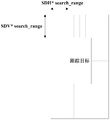
在本实施例中,对于当前帧,可以在前一帧得到的跟踪目标(例如对应该参考块)所在的位置周围设置搜索窗口。例如,可以首先设置一个参数search_range,搜索窗口的水平范围从–SDH*search_range+x到SDH*search_range+x+w,搜索窗口的垂直范围从–SDV*search_range+y到SDV*search_range+y+h。
图3是本发明实施例的搜索窗口的一示意图,如图3所示,可以在参考块的周围设置在当前帧中的搜索窗口。
值得注意的是,以上仅示意性示出了如何设置搜索窗口,但本发明不限于此,还可以采用其他的方式进行设置。通过设置搜索窗口,可以在不降低搜索的准确性的情况下减少计算量。
步骤204,根据所述参考块的尺寸、所述水平采样间隔和所述垂直采样间隔,从所述搜索窗口中抽取出一个或多个候选块;
在本实施例中,例如可以在搜索窗口内依次抽取与参考块相同大小的块作为候选块,水平抽取间隔为SDH,垂直抽取间隔为SDV。
图4是本发明实施例的抽取候选块的一示意图,如图4所示,可以在搜索窗口中抽取出一个或多个候选块。值得注意的是,以上仅示意性示出了如何抽取候选块,但本发明不限于此,还可以采用其他的方式进行设置。通过对候选块或者参考块进行采样,可以在不降低搜索的准确性的情况下减少计算量。
步骤205,为每个候选块和所述参考块生成特征向量;
在本实施例中,具体地对于某个候选块或者参考块,可以根据所述水平采样间隔和所述垂直采样间隔,对所述块中的像素进行采样;并利用采样得到的多个像素的特征值构造所述块的特征向量。
其中,特征向量可以包括如下:灰度特征向量和方向梯度直方图(HoG,Histogram of Oriented Gradient)特征向量,但本发明不限于此,例如还可以采用其他的特征向量。
在本实施例中,可以将采样得到的多个像素的灰度值构造成灰度特征向量;将采样得到的多个像素的HoG值构造成HoG特征向量;然后将所述灰度特征向量和所述HoG特征向量进行合并,得到所述候选块或者所述参考块的特征向量。
例如,对于某一候选块,可在该候选块内进行采样,水平采样间隔例如为2*SDH,垂直采样间隔例如为2*SDV。将采样得到的多个像素点的灰度值依次排列构成灰度特征向量。然后对采样得到的这些像素点计算HoG特征,将得到的HoG特征向量与灰度特征向量合并得到最终的块特征向量。
此外,还可以为灰度特征向量和HoG特征向量分别赋予权重系数;并且将赋予权重系数后的灰度特征向量和HoG特征向量进行合并。例如,在最终的特征向量中,灰度特征向量获得Wy的权重,HoG特征向量获得Wh的权重。
对于参考块,可以进行相同的处理。由此对于参考块可以获得一个特征向量,对于每个候选块也可以获得一个特征向量。
步骤206,计算参考块的特征向量与每个候选块的特征向量之间的矢量距离。
在本实施例中,关于两个特征向量之间如何计算矢量距离,可以参考相关技术。
步骤207,将与参考块的特征向量之间的矢量距离最小的候选块确定为当前尺寸的跟踪块;以及
步骤208,将最小的矢量距离作为当前尺寸的所述匹配值。
例如,与参考块的矢量距离最小的那个候选块所在的位置可以被确定为当前尺寸下的跟踪结果,与参考块的矢量距离最小的那个矢量距离可以被确定为当前尺寸下的匹配值。
值得注意的是,附图2仅示意性地对本发明实施例进行了说明,但本发明不限于此。例如可以适当地调整各个步骤之间的执行顺序,此外还可以增加其他的一些步骤或者减少其中的某些步骤。本领域的技术人员可以根据上述内容进行适当地变型,而不仅限于上述附图的记载。
由此,可以计算出例如正常尺寸下的匹配值以及候选块。然后可以通过上述步骤201至步骤208,分别计算缩小尺寸和放大尺寸下的匹配值以及候选块。
例如可以将跟踪目标缩放到一个较小的尺寸(例如正常尺寸的0.95),小尺寸目标的中心与正常尺寸目标的中心位置一致,长宽分别是正常尺寸目标的长宽乘上一个小于1的系数(例如0.95),将参考块也缩放到同样的尺寸上。
然后重复步骤201至步骤208,计算目标在小尺寸下的匹配值和跟踪结果。如果匹配值小于正常尺寸下的匹配值,用小尺寸下得到匹配值和跟踪结果替代正常尺寸下的匹配值和跟踪结果,否则,保留正常尺寸下的匹配值和跟踪结果。
再例如,将跟踪目标缩放到一个较大的尺寸(例如正常尺寸的1.05),大尺寸目标的中心与正常尺寸目标的中心位置一致,长宽分别是正常尺寸目标的长宽乘上一个大于1的系数(例如1.05),将参考块也缩放到同样的尺寸上。
然后重复步骤201至步骤208,计算目标在大尺寸下的匹配值和跟踪结果。如果匹配值小于之前保留的匹配值,用大尺寸下得到匹配值和跟踪结果替代之前的匹配值和跟踪结果,否则,保留之前的匹配值和跟踪结果。
值得注意的是,以上仅以正常尺寸、缩小尺寸和扩大尺寸这三种为例进行说明。但本发明不限于此,可以还可以是三种以上的尺寸,等等;可以根据需要确定具体的实施方式。
在本实施例中,还可以利用所述跟踪块的信息对所述参考块进行更新。
例如,将得到的跟踪结果所在的块缩放到参考块的大小,然后根据参考块的信息(例如灰度值)与跟踪结果所在块的信息(例如灰度值)对参考块进行更新。进一步地,可以将进行加权平均后的结果来更新参考块。
例如,Ref=learing_rate*Ref+(1-learing_rate)*Trk。其中,Ref表示参考块的信息,learing_rate表示权重系数,Trk表示跟踪结果所在块的信息。
由上述实施例可知,对于多个不同尺寸分别计算检测目标的参考块和所述检测目标在当前帧中一个或多个候选块之间的特征向量距离,并根据所述特征向量距离确定当前尺寸的匹配值以及候选块;根据所述多个不同尺寸的匹配值以及候选块,确定所述检测目标在当前帧中的跟踪结果。由此,即使检测目标在图像帧中明显地放大或者缩小,也不会降低目标跟踪的精度。
实施例2
本发明实施例提供一种目标跟踪装置,对视频中的检测目标进行跟踪。本实施例2对应于实施例1的目标跟踪方法,相同的内容不再赘述。
图5是本发明实施例的目标跟踪装置的一示意图,如图5所示,目标跟踪装置500包括:
尺寸确定单元501,其根据预定的缩放因子确定所述检测目标的多个不同尺寸;
候选确定单元502,其对于每一当前尺寸,计算所述检测目标的参考块和所述检测目标在当前帧中一个或多个候选块之间的特征向量距离,并根据所述特征向量距离确定所述当前尺寸的匹配值以及候选块;
结果确定单元503,其根据所述多个不同尺寸的匹配值以及候选块,确定所述检测目标在所述当前帧中的跟踪结果。
在本实施例中,所述多个不同尺寸包括:正常尺寸、缩小尺寸和扩大尺寸;但本发明不限于此。
图6是本发明实施例的目标跟踪装置的另一示意图,如图6所示,目标跟踪装置600包括:尺寸确定单元501,候选确定单元502以及结果确定单元503,如上所述。
如图6所示,目标跟踪装置600还可以包括:
参考块确定单元601,其对于所述当前尺寸确定所述检测目标的所述参考块;
间隔确定单元602,其根据所述参考块的尺寸确定水平采样间隔和垂直采样间隔。
如图6所示,目标跟踪装置600还可以包括:
参考块更新单元603,其利用跟踪块的信息对所述参考块进行更新。
图7是本发明实施例的候选确定单元502的一示意图,如图7所示,候选确定单元502可以包括:
窗口设置单元701,其根据所述参考块的位置、所述水平采样间隔和所述垂直采样间隔,设置在所述当前帧中的搜索窗口;
候选块抽取单元702,其根据所述参考块的尺寸、所述水平采样间隔和所述垂直采样间隔,从所述搜索窗口中抽取出一个或多个候选块;
向量生成单元703,其为每个候选块和所述参考块生成特征向量;以及
距离计算单元704,其计算所述参考块的特征向量与所述每个候选块的特征向量之间的矢量距离。
如图7所示,候选确定单元502还可以包括:
候选块确定单元705,其将与所述参考块的特征向量之间的矢量距离最小的候选块确定为所述当前尺寸的跟踪块;以及
匹配值确定单元706,其将最小的所述矢量距离作为所述当前尺寸的所述匹配值。
图8是本发明实施例的向量生成单元703的一示意图,如图8所示,向量生成单
元703可以包括:
像素采样单元801,其根据所述水平采样间隔和所述垂直采样间隔,对所述候选块或者所述参考块中的像素进行采样;
向量构造单元802,其利用采样得到的多个像素的特征值构造所述候选块或者所述参考块的特征向量。
图9是本发明实施例的向量构造单元802的一示意图,如图9所示,向量构造单元802可以包括:
第一向量构造单元901,其将采样得到的多个像素的灰度值构造成灰度特征向量;
第二向量构造单元902,其将采样得到的多个像素的方向梯度直方图值构造成方向梯度直方图特征向量;以及
向量合并单元903,其将所述灰度特征向量和所述方向梯度直方图特征向量进行合并,得到所述候选块或者所述参考块的特征向量。
如图9所示,向量构造单元802还可以包括:
权重赋予单元904,其为所述灰度特征向量和所述方向梯度直方图特征向量分别赋予权重系数;
并且向量合并单元903还用于:将赋予权重系数后的所述灰度特征向量和所述方向梯度直方图特征向量进行合并。
图10是本发明实施例的结果确定单元503的一示意图,如图10所示,结果确定单元503可以包括:
匹配值比较单元1001,其比较所述多个不同尺寸下的所述匹配值;以及
跟踪块确定单元1002,其将最小匹配值所对应的候选块确定为所述检测目标在所述当前帧中的跟踪块。
值得注意的是,以上仅对与本发明相关的各部件进行了说明,但本发明不限于此。目标跟踪装置还可以包括其他部件或者模块,关于这些部件或者模块的具体内容,可以参考现有技术。
由上述实施例可知,对于多个不同尺寸分别计算检测目标的参考块和所述检测目标在当前帧中一个或多个候选块之间的特征向量距离,并根据所述特征向量距离确定当前尺寸的匹配值以及候选块;根据所述多个不同尺寸的匹配值以及候选块,确定所述检测目标在当前帧中的跟踪结果。由此,即使检测目标在图像帧中明显地放大或者
缩小,也不会降低目标跟踪的精度。
实施例3
本发明实施例提供一种图像处理设备,该图像处理设备包括如实施例2所述的目标跟踪装置。
图11是本发明实施例的图像处理设备的一示意图。如图11所示,图像处理设备1100可以包括:中央处理器(CPU)100和存储器110;存储器110耦合到中央处理器100。其中该存储器110可存储各种数据;此外还存储信息处理的程序,并且在中央处理器100的控制下执行该程序。
在一个实施方式中,目标跟踪装置500或600的功能可以被集成到中央处理器100中。其中,中央处理器100可以被配置为实现如实施例1所述的目标跟踪方法。
在另一个实施方式中,目标跟踪装置500或600可以与中央处理器100分开配置,例如可以将目标跟踪装置500或600配置为与中央处理器100连接的芯片,通过中央处理器100的控制来实现目标跟踪装置500或600的功能。
在本实施例中,中央处理器100可以被配置为进行如下的控制:根据预定的缩放因子确定所述检测目标的多个不同尺寸;对于每一当前尺寸,计算所述检测目标的参考块和所述检测目标在当前帧中一个或多个候选块之间的特征向量距离,并根据所述特征向量距离确定所述当前尺寸的匹配值以及候选块;根据所述多个不同尺寸的匹配值以及候选块,确定所述检测目标在所述当前帧中的跟踪结果。
此外,如图11所示,图像处理设备1100还可以包括:输入输出(I/O)设备120和显示器130等;其中,上述部件的功能与现有技术类似,此处不再赘述。值得注意的是,图像处理设备1100也并不是必须要包括图11中所示的所有部件;此外,图像处理设备1100还可以包括图11中没有示出的部件,可以参考现有技术。
本发明实施例提供一种计算机可读程序,其中当在目标跟踪装置或图像处理设备中执行所述程序时,所述程序使得所述目标跟踪装置或图像处理设备执行如实施例1所述的目标跟踪方法。
本发明实施例提供一种存储有计算机可读程序的存储介质,其中所述计算机可读程序使得目标跟踪装置或图像处理设备执行如实施例1所述的目标跟踪方法。
本发明以上的装置和方法可以由硬件实现,也可以由硬件结合软件实现。本发明
涉及这样的计算机可读程序,当该程序被逻辑部件所执行时,能够使该逻辑部件实现上文所述的装置或构成部件,或使该逻辑部件实现上文所述的各种方法或步骤。本发明还涉及用于存储以上程序的存储介质,如硬盘、磁盘、光盘、DVD、flash存储器等。
结合本发明实施例描述的方法/装置可直接体现为硬件、由处理器执行的软件模块或二者组合。例如,图5中所示的功能框图中的一个或多个和/或功能框图的一个或多个组合(例如,尺寸确定单元、候选确定单元、结果确定单元等),既可以对应于计算机程序流程的各个软件模块,亦可以对应于各个硬件模块。这些软件模块,可以分别对应于图1所示的各个步骤。这些硬件模块例如可利用现场可编程门阵列(FPGA)将这些软件模块固化而实现。
软件模块可以位于RAM存储器、闪存、ROM存储器、EPROM存储器、EEPROM存储器、寄存器、硬盘、移动磁盘、CD-ROM或者本领域已知的任何其它形式的存储介质。可以将一种存储介质耦接至处理器,从而使处理器能够从该存储介质读取信息,且可向该存储介质写入信息;或者该存储介质可以是处理器的组成部分。处理器和存储介质可以位于ASIC中。该软件模块可以存储在移动终端的存储器中,也可以存储在可插入移动终端的存储卡中。例如,若设备(如移动终端)采用的是较大容量的MEGA-SIM卡或者大容量的闪存装置,则该软件模块可存储在该MEGA-SIM卡或者大容量的闪存装置中。
针对附图中描述的功能方框中的一个或多个和/或功能方框的一个或多个组合,可以实现为用于执行本申请所描述功能的通用处理器、数字信号处理器(DSP)、专用集成电路(ASIC)、现场可编程门阵列(FPGA)或者其它可编程逻辑器件、分立门或者晶体管逻辑器件、分立硬件组件或者其任意适当组合。针对附图描述的功能方框中的一个或多个和/或功能方框的一个或多个组合,还可以实现为计算设备的组合,例如,DSP和微处理器的组合、多个微处理器、与DSP通信结合的一个或多个微处理器或者任何其它这种配置。
以上结合具体的实施方式对本发明进行了描述,但本领域技术人员应该清楚,这些描述都是示例性的,并不是对本发明保护范围的限制。本领域技术人员可以根据本发明的精神和原理对本发明做出各种变型和修改,这些变型和修改也在本发明的范围内。
Claims (20)
- 一种目标跟踪方法,对视频中的检测目标进行跟踪,所述目标跟踪方法包括:根据预定的缩放因子确定所述检测目标的多个不同尺寸;对于每一当前尺寸,计算所述检测目标的参考块和所述检测目标在当前帧中一个或多个候选块之间的特征向量距离,并根据所述特征向量距离确定所述当前尺寸的匹配值以及候选块;根据所述多个不同尺寸的匹配值以及候选块,确定所述检测目标在所述当前帧中的跟踪结果。
- 根据权利要求1所述的目标跟踪方法,其中,所述多个不同尺寸包括:正常尺寸、缩小尺寸和扩大尺寸。
- 根据权利要求1所述的目标跟踪方法,其中,所述目标跟踪方法还包括:对于所述当前尺寸确定所述检测目标的所述参考块;根据所述参考块的尺寸确定水平采样间隔和垂直采样间隔。
- 根据权利要求3所述的目标跟踪方法,其中,计算所述检测目标的参考块和所述检测目标在当前帧中一个或多个候选块之间的特征向量距离,包括:根据所述参考块的位置、所述水平采样间隔和所述垂直采样间隔,设置在所述当前帧中的搜索窗口;根据所述参考块的尺寸、所述水平采样间隔和所述垂直采样间隔,从所述搜索窗口中抽取出一个或多个候选块;为每个候选块和所述参考块生成特征向量;以及计算所述参考块的特征向量与所述每个候选块的特征向量之间的矢量距离。
- 根据权利要求4所述的目标跟踪方法,其中,根据所述特征向量距离确定所述当前尺寸的匹配值以及候选块,包括:将与所述参考块的特征向量之间的矢量距离最小的候选块确定为所述当前尺寸的跟踪块;以及将最小的所述矢量距离作为所述当前尺寸的所述匹配值。
- 根据权利要求4所述的目标跟踪方法,其中,为每个候选块和所述参考块生成特征向量,包括:根据所述水平采样间隔和所述垂直采样间隔,对所述候选块或者所述参考块中的像素进行采样;利用采样得到的多个像素的特征值构造所述候选块或者所述参考块的特征向量。
- 根据权利要求6所述的目标跟踪方法,其中,利用采样得到的多个像素的特征值构造所述候选块或者所述参考块的特征向量,包括:将采样得到的多个像素的灰度值构造成灰度特征向量;将采样得到的多个像素的方向梯度直方图值构造成方向梯度直方图特征向量;将所述灰度特征向量和所述方向梯度直方图特征向量进行合并,得到所述候选块或者所述参考块的特征向量。
- 根据权利要求7所述的目标跟踪方法,其中,所述目标跟踪方法还包括:为所述灰度特征向量和所述方向梯度直方图特征向量分别赋予权重系数;并且将赋予权重系数后的所述灰度特征向量和所述方向梯度直方图特征向量进行合并。
- 根据权利要求1所述的目标跟踪方法,其中,根据所述多个不同尺寸的所述匹配值以及候选块确定所述检测目标在所述当前帧中的跟踪结果,包括:比较所述多个不同尺寸下的所述匹配值;以及将最小匹配值所对应的候选块确定为所述检测目标在所述当前帧中的跟踪块。
- 根据权利要求9所述的目标跟踪方法,其中,所述目标跟踪方法还包括:利用所述跟踪块的信息对所述参考块进行更新。
- 一种目标跟踪装置,对视频中的检测目标进行跟踪,所述目标跟踪装置包括:尺寸确定单元,其根据预定的缩放因子确定所述检测目标的多个不同尺寸;候选确定单元,其对于每一当前尺寸,计算所述检测目标的参考块和所述检测目标在当前帧中一个或多个候选块之间的特征向量距离,并根据所述特征向量距离确定所述当前尺寸的匹配值以及候选块;结果确定单元,其根据所述多个不同尺寸的匹配值以及候选块,确定所述检测目标在所述当前帧中的跟踪结果。
- 根据权利要求11所述的目标跟踪装置,其中,所述多个不同尺寸包括:正常尺寸、缩小尺寸和扩大尺寸。
- 根据权利要求11所述的目标跟踪装置,其中,所述目标跟踪装置还包括:参考块确定单元,其对于所述当前尺寸确定所述检测目标的所述参考块;间隔确定单元,其根据所述参考块的尺寸确定水平采样间隔和垂直采样间隔。
- 根据权利要求13所述的目标跟踪装置,其中,所述候选确定单元包括:窗口设置单元,其根据所述参考块的位置、所述水平采样间隔和所述垂直采样间隔,设置在所述当前帧中的搜索窗口;候选块抽取单元,其根据所述参考块的尺寸、所述水平采样间隔和所述垂直采样间隔,从所述搜索窗口中抽取出一个或多个候选块;向量生成单元,其为每个候选块和所述参考块生成特征向量;以及距离计算单元,其计算所述参考块的特征向量与所述每个候选块的特征向量之间的矢量距离。
- 根据权利要求14所述的目标跟踪装置,其中,所述候选确定单元还包括:候选块确定单元,其将与所述参考块的特征向量之间的矢量距离最小的候选块确定为所述当前尺寸的跟踪块;以及匹配值确定单元,其将最小的所述矢量距离作为所述当前尺寸的所述匹配值。
- 根据权利要求14所述的目标跟踪装置,其中,所述向量生成单元包括:像素采样单元,其根据所述水平采样间隔和所述垂直采样间隔,对所述候选块或者所述参考块中的像素进行采样;向量构造单元,其利用采样得到的多个像素的特征值构造所述候选块或者所述参考块的特征向量。
- 根据权利要求16所述的目标跟踪装置,其中,所述向量构造单元包括:第一向量构造单元,其将采样得到的多个像素的灰度值构造成灰度特征向量;第二向量构造单元,其将采样得到的多个像素的方向梯度直方图值构造成方向梯度直方图特征向量;以及向量合并单元,其将所述灰度特征向量和所述方向梯度直方图特征向量进行合并,得到所述候选块或者所述参考块的特征向量。
- 根据权利要求11所述的目标跟踪装置,其中,所述结果确定单元包括:匹配值比较单元,其比较所述多个不同尺寸下的所述匹配值;以及跟踪块确定单元,其将最小匹配值所对应的候选块确定为所述检测目标在所述当前帧中的跟踪块。
- 根据权利要求18所述的目标跟踪装置,其中,所述目标跟踪装置还包括:参考块更新单元,其利用所述跟踪块的信息对所述参考块进行更新。
- 一种图像处理设备,其中,所述图像处理设备包括如权利要求11所述的目标跟踪装置。
Priority Applications (2)
| Application Number | Priority Date | Filing Date | Title |
|---|---|---|---|
| CN201680087596.0A CN109478328A (zh) | 2016-09-30 | 2016-09-30 | 目标跟踪方法、装置以及图像处理设备 |
| PCT/CN2016/101094 WO2018058531A1 (zh) | 2016-09-30 | 2016-09-30 | 目标跟踪方法、装置以及图像处理设备 |
Applications Claiming Priority (1)
| Application Number | Priority Date | Filing Date | Title |
|---|---|---|---|
| PCT/CN2016/101094 WO2018058531A1 (zh) | 2016-09-30 | 2016-09-30 | 目标跟踪方法、装置以及图像处理设备 |
Publications (1)
| Publication Number | Publication Date |
|---|---|
| WO2018058531A1 true WO2018058531A1 (zh) | 2018-04-05 |
Family
ID=61762478
Family Applications (1)
| Application Number | Title | Priority Date | Filing Date |
|---|---|---|---|
| PCT/CN2016/101094 Ceased WO2018058531A1 (zh) | 2016-09-30 | 2016-09-30 | 目标跟踪方法、装置以及图像处理设备 |
Country Status (2)
| Country | Link |
|---|---|
| CN (1) | CN109478328A (zh) |
| WO (1) | WO2018058531A1 (zh) |
Cited By (1)
| Publication number | Priority date | Publication date | Assignee | Title |
|---|---|---|---|---|
| CN119946259A (zh) * | 2018-12-25 | 2025-05-06 | Oppo广东移动通信有限公司 | 解码预测方法、装置及计算机存储介质 |
Families Citing this family (1)
| Publication number | Priority date | Publication date | Assignee | Title |
|---|---|---|---|---|
| CN113269007B (zh) * | 2020-02-14 | 2025-04-25 | 富士通株式会社 | 道路监控视频的目标跟踪装置以及方法 |
Citations (10)
| Publication number | Priority date | Publication date | Assignee | Title |
|---|---|---|---|---|
| CN101739692A (zh) * | 2009-12-29 | 2010-06-16 | 天津市亚安科技电子有限公司 | 实时视频目标的快速相关跟踪方法 |
| CN101888479A (zh) * | 2009-05-14 | 2010-11-17 | 汉王科技股份有限公司 | 检测和跟踪目标图像的方法及装置 |
| CN103049749A (zh) * | 2012-12-30 | 2013-04-17 | 信帧电子技术(北京)有限公司 | 在栅格遮挡下的人体再识别方法 |
| CN103179335A (zh) * | 2011-09-01 | 2013-06-26 | 瑞萨电子株式会社 | 对象跟踪装置 |
| US8582821B1 (en) * | 2011-05-23 | 2013-11-12 | A9.Com, Inc. | Tracking objects between images |
| CN103632382A (zh) * | 2013-12-19 | 2014-03-12 | 中国矿业大学(北京) | 一种基于压缩感知的实时多尺度目标跟踪方法 |
| CN103996208A (zh) * | 2014-05-21 | 2014-08-20 | 国家电网公司 | 一种在视频图像中进行ptz单个目标自动跟踪方法 |
| CN105184779A (zh) * | 2015-08-26 | 2015-12-23 | 电子科技大学 | 一种基于快速特征金字塔的车辆多尺度跟踪方法 |
| CN105787964A (zh) * | 2016-02-29 | 2016-07-20 | 深圳电科技有限公司 | 目标跟踪方法和装置 |
| CN105913453A (zh) * | 2016-04-01 | 2016-08-31 | 海信集团有限公司 | 一种目标跟踪方法和装置 |
Family Cites Families (7)
| Publication number | Priority date | Publication date | Assignee | Title |
|---|---|---|---|---|
| KR100331050B1 (ko) * | 2000-06-01 | 2002-04-19 | 송종수 | 동영상 데이터상의 객체 추적 방법 |
| JP4578864B2 (ja) * | 2004-06-03 | 2010-11-10 | パナソニック株式会社 | 自動追尾装置及び自動追尾方法 |
| JP4047879B2 (ja) * | 2005-08-23 | 2008-02-13 | 松下電器産業株式会社 | 動きベクトル検出装置および動きベクトル検出方法 |
| JP4915655B2 (ja) * | 2006-10-27 | 2012-04-11 | パナソニック株式会社 | 自動追尾装置 |
| CN102456225B (zh) * | 2010-10-22 | 2014-07-09 | 深圳中兴力维技术有限公司 | 一种运动目标检测与跟踪方法和系统 |
| KR101758684B1 (ko) * | 2012-07-23 | 2017-07-14 | 한화테크윈 주식회사 | 객체 추적 장치 및 방법 |
| CN104424638A (zh) * | 2013-08-27 | 2015-03-18 | 深圳市安芯数字发展有限公司 | 一种基于遮挡情况下的目标跟踪方法 |
-
2016
- 2016-09-30 CN CN201680087596.0A patent/CN109478328A/zh active Pending
- 2016-09-30 WO PCT/CN2016/101094 patent/WO2018058531A1/zh not_active Ceased
Patent Citations (10)
| Publication number | Priority date | Publication date | Assignee | Title |
|---|---|---|---|---|
| CN101888479A (zh) * | 2009-05-14 | 2010-11-17 | 汉王科技股份有限公司 | 检测和跟踪目标图像的方法及装置 |
| CN101739692A (zh) * | 2009-12-29 | 2010-06-16 | 天津市亚安科技电子有限公司 | 实时视频目标的快速相关跟踪方法 |
| US8582821B1 (en) * | 2011-05-23 | 2013-11-12 | A9.Com, Inc. | Tracking objects between images |
| CN103179335A (zh) * | 2011-09-01 | 2013-06-26 | 瑞萨电子株式会社 | 对象跟踪装置 |
| CN103049749A (zh) * | 2012-12-30 | 2013-04-17 | 信帧电子技术(北京)有限公司 | 在栅格遮挡下的人体再识别方法 |
| CN103632382A (zh) * | 2013-12-19 | 2014-03-12 | 中国矿业大学(北京) | 一种基于压缩感知的实时多尺度目标跟踪方法 |
| CN103996208A (zh) * | 2014-05-21 | 2014-08-20 | 国家电网公司 | 一种在视频图像中进行ptz单个目标自动跟踪方法 |
| CN105184779A (zh) * | 2015-08-26 | 2015-12-23 | 电子科技大学 | 一种基于快速特征金字塔的车辆多尺度跟踪方法 |
| CN105787964A (zh) * | 2016-02-29 | 2016-07-20 | 深圳电科技有限公司 | 目标跟踪方法和装置 |
| CN105913453A (zh) * | 2016-04-01 | 2016-08-31 | 海信集团有限公司 | 一种目标跟踪方法和装置 |
Cited By (2)
| Publication number | Priority date | Publication date | Assignee | Title |
|---|---|---|---|---|
| CN119946259A (zh) * | 2018-12-25 | 2025-05-06 | Oppo广东移动通信有限公司 | 解码预测方法、装置及计算机存储介质 |
| CN119946259B (zh) * | 2018-12-25 | 2025-11-21 | Oppo广东移动通信有限公司 | 解码预测方法、装置及计算机存储介质 |
Also Published As
| Publication number | Publication date |
|---|---|
| CN109478328A (zh) | 2019-03-15 |
Similar Documents
| Publication | Publication Date | Title |
|---|---|---|
| US9576367B2 (en) | Object detection method and device | |
| CN113674421B (zh) | 3d目标检测方法、模型训练方法、相关装置及电子设备 | |
| CN108027877B (zh) | 用于非障碍区检测的系统和方法 | |
| CN107507225B (zh) | 运动目标检测方法、装置、介质及计算设备 | |
| CN109948637B (zh) | 对象检测装置、对象检测方法及计算机可读介质 | |
| CN108230292B (zh) | 物体检测方法和神经网络的训练方法、装置及电子设备 | |
| CN108381549B (zh) | 一种双目视觉引导机器人快速抓取方法、装置及存储介质 | |
| KR102458242B1 (ko) | 스테레오 카메라로부터 획득된 이미지 페어를 처리하는 장치 및 방법 | |
| CN111383252B (zh) | 多相机目标追踪方法、系统、装置及存储介质 | |
| CN105574894A (zh) | 一种运动物体特征点跟踪结果的筛选方法和系统 | |
| CN113112525A (zh) | 目标跟踪方法、网络模型及其训练方法、设备和介质 | |
| CN114586059B (zh) | 图像的配准方法、终端以及计算机存储介质 | |
| CN107749069B (zh) | 图像处理方法、电子设备和图像处理系统 | |
| CN114267027A (zh) | 一种图像处理方法和装置 | |
| CN114596516B (zh) | 目标跟踪方法、装置、电子设备及计算机可读存储介质 | |
| CN109344801A (zh) | 一种物体检测方法及装置 | |
| CN116977671A (zh) | 基于图像空间定位的目标跟踪方法、装置、设备及存储介质 | |
| WO2021128314A1 (zh) | 一种图像处理方法、设备、图像处理系统及存储介质 | |
| WO2018058531A1 (zh) | 目标跟踪方法、装置以及图像处理设备 | |
| CN112507951B (zh) | 指示灯识别方法、装置、设备、路侧设备和云控平台 | |
| CN113971671B (zh) | 实例分割方法、装置、电子设备及存储介质 | |
| CN112837349A (zh) | 一种目标跟踪方法、设备及计算机可读存储介质 | |
| CN119559494A (zh) | 遥感图像目标检测方法、装置、计算机设备及存储介质 | |
| CN114596580B (zh) | 一种多人体目标识别方法、系统、设备及介质 | |
| CN115830304A (zh) | 物体检测系统 |
Legal Events
| Date | Code | Title | Description |
|---|---|---|---|
| 121 | Ep: the epo has been informed by wipo that ep was designated in this application |
Ref document number: 16917281 Country of ref document: EP Kind code of ref document: A1 |
|
| NENP | Non-entry into the national phase |
Ref country code: DE |
|
| 122 | Ep: pct application non-entry in european phase |
Ref document number: 16917281 Country of ref document: EP Kind code of ref document: A1 |