WO2018056448A1 - Secondary battery state detection device and secondary battery state detection method - Google Patents
Secondary battery state detection device and secondary battery state detection method Download PDFInfo
- Publication number
- WO2018056448A1 WO2018056448A1 PCT/JP2017/034595 JP2017034595W WO2018056448A1 WO 2018056448 A1 WO2018056448 A1 WO 2018056448A1 JP 2017034595 W JP2017034595 W JP 2017034595W WO 2018056448 A1 WO2018056448 A1 WO 2018056448A1
- Authority
- WO
- WIPO (PCT)
- Prior art keywords
- secondary battery
- charging
- voltage
- value
- resistance
- Prior art date
Links
Images


Classifications
-
- H—ELECTRICITY
- H02—GENERATION; CONVERSION OR DISTRIBUTION OF ELECTRIC POWER
- H02J—CIRCUIT ARRANGEMENTS OR SYSTEMS FOR SUPPLYING OR DISTRIBUTING ELECTRIC POWER; SYSTEMS FOR STORING ELECTRIC ENERGY
- H02J7/00—Circuit arrangements for charging or depolarising batteries or for supplying loads from batteries
- H02J7/0047—Circuit arrangements for charging or depolarising batteries or for supplying loads from batteries with monitoring or indicating devices or circuits
- H02J7/0048—Detection of remaining charge capacity or state of charge [SOC]
-
- B—PERFORMING OPERATIONS; TRANSPORTING
- B60—VEHICLES IN GENERAL
- B60R—VEHICLES, VEHICLE FITTINGS, OR VEHICLE PARTS, NOT OTHERWISE PROVIDED FOR
- B60R16/00—Electric or fluid circuits specially adapted for vehicles and not otherwise provided for; Arrangement of elements of electric or fluid circuits specially adapted for vehicles and not otherwise provided for
- B60R16/02—Electric or fluid circuits specially adapted for vehicles and not otherwise provided for; Arrangement of elements of electric or fluid circuits specially adapted for vehicles and not otherwise provided for electric constitutive elements
- B60R16/04—Arrangement of batteries
-
- G—PHYSICS
- G01—MEASURING; TESTING
- G01R—MEASURING ELECTRIC VARIABLES; MEASURING MAGNETIC VARIABLES
- G01R31/00—Arrangements for testing electric properties; Arrangements for locating electric faults; Arrangements for electrical testing characterised by what is being tested not provided for elsewhere
- G01R31/36—Arrangements for testing, measuring or monitoring the electrical condition of accumulators or electric batteries, e.g. capacity or state of charge [SoC]
- G01R31/367—Software therefor, e.g. for battery testing using modelling or look-up tables
-
- G—PHYSICS
- G01—MEASURING; TESTING
- G01R—MEASURING ELECTRIC VARIABLES; MEASURING MAGNETIC VARIABLES
- G01R31/00—Arrangements for testing electric properties; Arrangements for locating electric faults; Arrangements for electrical testing characterised by what is being tested not provided for elsewhere
- G01R31/36—Arrangements for testing, measuring or monitoring the electrical condition of accumulators or electric batteries, e.g. capacity or state of charge [SoC]
- G01R31/382—Arrangements for monitoring battery or accumulator variables, e.g. SoC
- G01R31/3842—Arrangements for monitoring battery or accumulator variables, e.g. SoC combining voltage and current measurements
-
- G—PHYSICS
- G01—MEASURING; TESTING
- G01R—MEASURING ELECTRIC VARIABLES; MEASURING MAGNETIC VARIABLES
- G01R31/00—Arrangements for testing electric properties; Arrangements for locating electric faults; Arrangements for electrical testing characterised by what is being tested not provided for elsewhere
- G01R31/36—Arrangements for testing, measuring or monitoring the electrical condition of accumulators or electric batteries, e.g. capacity or state of charge [SoC]
- G01R31/385—Arrangements for measuring battery or accumulator variables
- G01R31/387—Determining ampere-hour charge capacity or SoC
- G01R31/388—Determining ampere-hour charge capacity or SoC involving voltage measurements
-
- G—PHYSICS
- G01—MEASURING; TESTING
- G01R—MEASURING ELECTRIC VARIABLES; MEASURING MAGNETIC VARIABLES
- G01R31/00—Arrangements for testing electric properties; Arrangements for locating electric faults; Arrangements for electrical testing characterised by what is being tested not provided for elsewhere
- G01R31/36—Arrangements for testing, measuring or monitoring the electrical condition of accumulators or electric batteries, e.g. capacity or state of charge [SoC]
- G01R31/389—Measuring internal impedance, internal conductance or related variables
-
- H—ELECTRICITY
- H01—ELECTRIC ELEMENTS
- H01M—PROCESSES OR MEANS, e.g. BATTERIES, FOR THE DIRECT CONVERSION OF CHEMICAL ENERGY INTO ELECTRICAL ENERGY
- H01M10/00—Secondary cells; Manufacture thereof
- H01M10/42—Methods or arrangements for servicing or maintenance of secondary cells or secondary half-cells
- H01M10/425—Structural combination with electronic components, e.g. electronic circuits integrated to the outside of the casing
-
- H—ELECTRICITY
- H01—ELECTRIC ELEMENTS
- H01M—PROCESSES OR MEANS, e.g. BATTERIES, FOR THE DIRECT CONVERSION OF CHEMICAL ENERGY INTO ELECTRICAL ENERGY
- H01M10/00—Secondary cells; Manufacture thereof
- H01M10/42—Methods or arrangements for servicing or maintenance of secondary cells or secondary half-cells
- H01M10/48—Accumulators combined with arrangements for measuring, testing or indicating the condition of cells, e.g. the level or density of the electrolyte
-
- H—ELECTRICITY
- H02—GENERATION; CONVERSION OR DISTRIBUTION OF ELECTRIC POWER
- H02J—CIRCUIT ARRANGEMENTS OR SYSTEMS FOR SUPPLYING OR DISTRIBUTING ELECTRIC POWER; SYSTEMS FOR STORING ELECTRIC ENERGY
- H02J7/00—Circuit arrangements for charging or depolarising batteries or for supplying loads from batteries
- H02J7/14—Circuit arrangements for charging or depolarising batteries or for supplying loads from batteries for charging batteries from dynamo-electric generators driven at varying speed, e.g. on vehicle
-
- H—ELECTRICITY
- H01—ELECTRIC ELEMENTS
- H01M—PROCESSES OR MEANS, e.g. BATTERIES, FOR THE DIRECT CONVERSION OF CHEMICAL ENERGY INTO ELECTRICAL ENERGY
- H01M10/00—Secondary cells; Manufacture thereof
- H01M10/42—Methods or arrangements for servicing or maintenance of secondary cells or secondary half-cells
- H01M10/425—Structural combination with electronic components, e.g. electronic circuits integrated to the outside of the casing
- H01M2010/4278—Systems for data transfer from batteries, e.g. transfer of battery parameters to a controller, data transferred between battery controller and main controller
-
- H—ELECTRICITY
- H01—ELECTRIC ELEMENTS
- H01M—PROCESSES OR MEANS, e.g. BATTERIES, FOR THE DIRECT CONVERSION OF CHEMICAL ENERGY INTO ELECTRICAL ENERGY
- H01M2220/00—Batteries for particular applications
- H01M2220/20—Batteries in motive systems, e.g. vehicle, ship, plane
-
- H—ELECTRICITY
- H02—GENERATION; CONVERSION OR DISTRIBUTION OF ELECTRIC POWER
- H02J—CIRCUIT ARRANGEMENTS OR SYSTEMS FOR SUPPLYING OR DISTRIBUTING ELECTRIC POWER; SYSTEMS FOR STORING ELECTRIC ENERGY
- H02J2310/00—The network for supplying or distributing electric power characterised by its spatial reach or by the load
- H02J2310/40—The network being an on-board power network, i.e. within a vehicle
- H02J2310/46—The network being an on-board power network, i.e. within a vehicle for ICE-powered road vehicles
-
- H—ELECTRICITY
- H02—GENERATION; CONVERSION OR DISTRIBUTION OF ELECTRIC POWER
- H02J—CIRCUIT ARRANGEMENTS OR SYSTEMS FOR SUPPLYING OR DISTRIBUTING ELECTRIC POWER; SYSTEMS FOR STORING ELECTRIC ENERGY
- H02J7/00—Circuit arrangements for charging or depolarising batteries or for supplying loads from batteries
- H02J7/0047—Circuit arrangements for charging or depolarising batteries or for supplying loads from batteries with monitoring or indicating devices or circuits
- H02J7/0048—Detection of remaining charge capacity or state of charge [SOC]
- H02J7/0049—Detection of fully charged condition
-
- Y—GENERAL TAGGING OF NEW TECHNOLOGICAL DEVELOPMENTS; GENERAL TAGGING OF CROSS-SECTIONAL TECHNOLOGIES SPANNING OVER SEVERAL SECTIONS OF THE IPC; TECHNICAL SUBJECTS COVERED BY FORMER USPC CROSS-REFERENCE ART COLLECTIONS [XRACs] AND DIGESTS
- Y02—TECHNOLOGIES OR APPLICATIONS FOR MITIGATION OR ADAPTATION AGAINST CLIMATE CHANGE
- Y02E—REDUCTION OF GREENHOUSE GAS [GHG] EMISSIONS, RELATED TO ENERGY GENERATION, TRANSMISSION OR DISTRIBUTION
- Y02E60/00—Enabling technologies; Technologies with a potential or indirect contribution to GHG emissions mitigation
- Y02E60/10—Energy storage using batteries
Definitions
- the present invention relates to a secondary battery state detection device and a secondary battery state detection method.
- Patent Documents 1 to 3 As a technique for detecting that the secondary battery is fully charged, for example, there are techniques disclosed in Patent Documents 1 to 3.
- Patent Document 1 the voltage value and the current value are plotted on the current-voltage plane, and it is determined whether or not the secondary battery has reached the charge acceptance limit according to the position of the plotted point on the current-voltage plane. Techniques to do this are disclosed.
- Patent Document 2 discloses a technique for obtaining a reaction resistance of a charging reaction of a secondary battery from the relationship between current and voltage at the time of charging, and detecting a full charge of the secondary battery from an increase in the reaction resistance. Yes.
- Patent Document 3 discloses that full charge detection and full charge detection are performed based on the difference ( ⁇ V) between the voltage during charging and the open circuit voltage OCV and the internal resistance (Rohm, Rct1,%) Obtained separately.
- ⁇ V difference between the voltage during charging and the open circuit voltage OCV and the internal resistance (Rohm, Rct1,%) Obtained separately.
- a technique for calculating the SOC is disclosed.
- the present invention has been made in view of the above situation, and a secondary battery state detection device capable of accurately detecting the full charge of the secondary battery even when the power generation voltage of the alternator changes, and
- An object of the present invention is to provide a secondary battery state detection method.
- the present invention provides a secondary battery state detection device for detecting a state of a secondary battery, wherein one or a plurality of processors and one or a plurality of the processors are connected to be communicable with each other.
- a plurality of memories wherein one or more of the processors reads a group of instructions stored in the one or more of the memories, and charging when an alternator capable of adjusting a generated voltage charges the secondary battery
- An estimation process for estimating a charge rate of the secondary battery is executed based on the charging resistance calculated by the process. According to such a configuration, even when the power generation voltage of the alternator changes, it becomes possible to accurately detect the full charge of the secondary battery.
- the estimation process is a full charge or a predetermined charge rate when the value of the charging resistance calculated by the calculation process is equal to or greater than a predetermined threshold that is a fluctuation value.
- the threshold value varies such that the value decreases as the value of the charging voltage detected by the detection process increases. According to such a configuration, even when the power generation voltage of the alternator changes, it can be accurately detected that the battery is fully charged or has a predetermined charging rate (for example, a charging rate of 90%).
- the present invention estimates that the estimation process is a predetermined charge rate when the value of the charging resistance calculated by the calculation process is equal to or greater than a predetermined threshold which is a fixed value.
- the estimated predetermined charging rate increases as the value of the charging voltage detected by the detection process increases. According to such a configuration, even when the power generation voltage of the alternator changes, it is possible to accurately detect that the predetermined charging rate determined by the charging voltage has been reached.
- the present invention estimates that the estimation process is a predetermined charge rate when the value of the charging resistance calculated by the calculation process is equal to or greater than a predetermined threshold that is a fluctuation value.
- the threshold fluctuates so that the value decreases as the value of the charging voltage detected by the detection process increases, and the predetermined charging rate increases as the value of the charging voltage detected by the detection process increases. The value is increased. According to such a configuration, even when the power generation voltage of the alternator changes, it is possible to accurately detect that the predetermined charging rate determined by the charging voltage is reached, and adjust the predetermined charging rate for each charging voltage. can do.
- the present invention is characterized in that the calculation processing calculates the charging resistance by dividing a difference value between the charging voltage and an open circuit voltage by a charging current. According to such a configuration, the charging resistance can be easily obtained.
- the equivalent circuit model of the secondary battery is learned from a relationship between voltage and current at the time of discharging the secondary battery, and the charging resistance is determined by a resistance element of the obtained equivalent circuit model. Is calculated. According to such a configuration, the charging resistance can be obtained more accurately using an equivalent circuit model.
- the present invention provides an equivalent circuit model of the secondary battery for the voltage and current when the secondary battery is discharged when the secondary battery is estimated to be fully charged or the predetermined charging rate by the estimation process.
- the charging rate is calculated based on the ratio between the resistance element of the equivalent circuit model obtained by learning from the relationship and the charging resistance calculated by dividing the difference value between the charging voltage and the open circuit voltage by the charging current.
- the said charging rate is made into the said charging rate at that time, It is characterized by the above-mentioned. According to such a configuration, it is possible to accurately obtain the charging rate when it is determined that the battery is fully charged or a predetermined charging rate.
- a secondary battery state detection method for detecting a state of a secondary battery, wherein an alternator capable of adjusting a power generation voltage detects a charging voltage when the secondary battery is charged by an output from a voltage sensor.
- a detection step a calculation step for calculating a charging resistance as an internal resistance of the secondary battery when the alternator charges the secondary battery; the charging voltage detected in the detection step; and the calculation step.
- the present invention it is possible to provide a secondary battery state detection device and a secondary battery state detection method capable of accurately detecting the full charge of the secondary battery even when the power generation voltage of the alternator changes. It becomes.
- FIG. 1 shows the structural example of the secondary battery state detection apparatus which concerns on 1st Embodiment of this invention. It is a block diagram which shows the detailed structural example of the control part of FIG. It is a figure for demonstrating operation
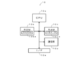
- FIG. 1 is a diagram showing a power supply system of a vehicle having a secondary battery state detection device according to the first embodiment of the present invention.
- the secondary battery state detection device 1 includes a control unit 10, a voltage sensor 11, a current sensor 12, a temperature sensor 13, and a discharge circuit 15 as main components, and indicates the charge state of the secondary battery 14.
- the control unit 10 refers to the outputs from the voltage sensor 11, the current sensor 12, and the temperature sensor 13, detects the state of the secondary battery 14, and controls the power generation voltage of the alternator 16 to control the power generation voltage.
- the charging state of the secondary battery 14 is controlled.
- the voltage sensor 11 detects the terminal voltage of the secondary battery 14 and notifies the control unit 10 of it.
- the current sensor 12 detects the current flowing through the secondary battery 14 and notifies the control unit 10 of the current.
- the temperature sensor 13 detects the electrolyte solution of the secondary battery 14 or the ambient environmental temperature and notifies the control unit 10 of it.
- the discharge circuit 15 is configured by, for example, a semiconductor switch and a resistance element connected in series, and the control unit 10 controls the semiconductor switch to be turned on / off so that the secondary battery 14 is commanded to the secondary battery state detection device 1. Discharge according to
- the secondary battery 14 is constituted by a secondary battery having an electrolytic solution, such as a lead storage battery, a nickel cadmium battery, or a nickel metal hydride battery, and is charged by an alternator 16 to drive a starter motor 18 to start an engine. At the same time, power is supplied to the load 19.
- the alternator 16 is driven by the engine 17 to generate AC power, convert it into DC power by a rectifier circuit, and charge the secondary battery 14.
- the alternator 16 is controlled by the control unit 10 and can adjust the generated voltage.
- the engine 17 is constituted by, for example, a reciprocating engine such as a gasoline engine and a diesel engine, a rotary engine, or the like, and is started by a starter motor 18 to drive driving wheels through a transmission to provide propulsive force to the vehicle.
- the starter motor 18 is constituted by, for example, a DC motor, generates a rotational force by the electric power supplied from the secondary battery 14, and starts the engine 17.
- the load 19 is constituted by, for example, an electric steering motor, a defogger, a seat heater, an ignition coil, a car audio, a car navigation, and the like, and operates with electric power from the secondary battery 14.
- FIG. 2 is a diagram showing a detailed configuration example of the control unit 10 shown in FIG.
- the control unit 10 is, for example, a one-chip microcomputer, and includes a CPU (Central Processing Unit) 10a, a ROM (Read Only Memory) 10b, a RAM (Random Access Memory) 10c, and a communication unit 10d, I. / F (Interface) 10e.
- the CPU 10a controls each unit based on the program 10ba stored in the ROM 10b.
- the ROM 10b is configured by a semiconductor memory or the like, and stores a program 10ba or the like.
- the RAM 10c is configured by a semiconductor memory or the like, and stores data generated when the program 10ba is executed, and parameters 10ca such as mathematical formulas or tables described later.
- the communication unit 10d communicates with an upper device such as an ECU (Electronic Control Unit), and notifies the detected information or control information to the upper device.
- the I / F 10e converts the signals supplied from the voltage sensor 11, the current sensor 12, and the temperature sensor 13 into digital signals and takes them in, and supplies drive current to the discharge circuit 15, the alternator 16, the starter motor 18, and the like. Supply them to control them.
- each of the CPU 10a, the ROM 10b, and the RAM 10c is provided one by one, but a plurality of these may be provided. Further, a DSP (Digital Signal Processor) may be used instead of the CPU 10a.
- DSP Digital Signal Processor
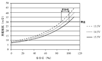
- FIG. 3 is a diagram showing the relationship between the SOC (State of charge) of the secondary battery 14 and the charging resistance when the secondary battery 14 is charged by changing the power generation voltage of the alternator 16.
- the solid curve indicates the relationship between the SOC and the charging resistance of the secondary battery 14 when charged at a voltage of 15.5 V
- the broken line curve with a short interval is when charged at a voltage of 14.5 V
- the relationship between the SOC and the charging resistance is shown
- the long dashed curve indicates the relationship between the SOC and the charging resistance when charging is performed at a voltage of 13.5V.
- the charging resistance refers to an electrical resistance inside the secondary battery 14 when the secondary battery 14 is charged by the alternator 16, and more specifically, for example, the secondary battery 14 is charged.
- the voltage V applied to the secondary battery 14, the open circuit voltage OCV, and the resistance R obtained from the current I ( (V ⁇ OCV) / I).
- the charging resistance may be obtained by a method other than that described above.
- the secondary battery 14 Full charge can be detected.
- the determination is made using the threshold value Th1
- the threshold value Th2 is used for determination. According to such a method, even when the power generation voltage of the alternator 16 changes, it is possible to accurately detect that the secondary battery 14 is fully charged.
- the thresholds Th1 to Th3 are determined for each charging voltage. However, as will be described later with reference to FIG. 5, the reference threshold Th is corrected according to the charging voltage, and Th ′ And this threshold Th ′ may be used for determination.
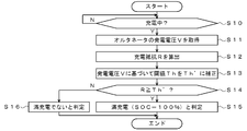
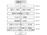
- step S10 the control unit 10 refers to the output of the current sensor 12, determines whether or not the secondary battery 14 is being charged by the alternator 16, and determines that charging is being performed (step S10: Y). Proceeds to step S11, and otherwise repeats the same processing (step S10: N). If charging is not being performed, the same processing may be repeated instead of repeating the same processing.
- step S11 the control unit 10 refers to the output of the voltage sensor 11 and acquires the generated voltage V of the alternator 16. As a result, for example, a voltage such as 15.5 V is acquired.
- step S14 the control unit 10 compares the charging resistance R calculated in step S12 with the corrected threshold value Th ′ obtained in step S13, and when R ⁇ Th ′ is satisfied (step S14: Y). Proceeds to step S15, otherwise proceeds to step S16 (step S14: N).
- step S16 the control unit 10 determines that the battery is not fully charged. As a result, the control unit 10 continues to drive the alternator 16 by the engine 17 to continue charging until the secondary battery 14 is fully charged.
- the reference threshold value Th is corrected according to the generated voltage of the alternator 16, and the fully charged state can be determined based on the corrected threshold value Th ′.
- the state of charge can be accurately determined.
- a threshold value Th that is a fixed value as shown in FIG. 6 is used. Then, when the charging resistance is equal to or higher than the threshold Th, and when the charging voltage is 13.5 V, it is determined that the charging rate is SOC1. Further, when the charging resistance is equal to or higher than the threshold Th, and when the charging voltage is 14.5 V, it is determined that the charging rate is SOC2. Further, when the charging resistance is equal to or higher than the threshold Th, and when the charging voltage is 15.5 V, it is determined that the charging rate is SOC3.
- threshold value Th when the alternator 16 supplies and supplies the maximum generated voltage, it is desirable to use Th that the charging rate becomes 100% or less. For example, when the maximum generated voltage is 15.5 V, it is desirable to set Th so that SOC3 ⁇ 100%. By setting in this way, even when the power generation voltage of the alternator 16 changes, it is possible to prevent the SOC from exceeding 100% and continuing charging.
- SOC1 to SOC3 are selected according to the charging voltage.
- a reference SOC reference SOC
- the reference SOC is corrected according to the charging voltage. May be.
- step S31 to step S33 is added when FIG. 5 is compared. Therefore, the processing of step S31 to step S33 will be mainly described below.
- step S31 the control unit 10 compares the charging resistance R calculated in step S12 with a threshold Th to determine whether or not R ⁇ Th is established, and when it is determined that R ⁇ Th is established (step S31: In Y), the process proceeds to step S32, and in other cases (step S31: N), the process ends.
- the threshold Th shown in FIG. 6 is compared with the charging resistance R, and if it is determined that R ⁇ Th, the process proceeds to step S32.
- step S32 the control unit 10 sets a reference SOC. More specifically, for example, the control unit 10 sets the SOC 3 shown in FIG. 7 as the reference SOC. Of course, other SOCs may be used as the reference SOC.
- the reference SOC may be corrected in consideration of the temperature of the secondary battery 14 detected by the temperature sensor 13. .
- the reference SOC is corrected according to the power generation voltage of the alternator 16, so that the SOC can be accurately adjusted even when the power generation voltage fluctuates. Charging control can be performed.
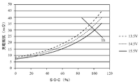
- the determination is made using a threshold value parallel to the X axis (horizontal axis).
- a threshold value Th having an inclination with respect to the X axis is set. You may make it use. That is, full charge may be determined by comparing Th (V) with the charging resistance R using Th (V) which is a function of the generated voltage instead of the fixed value Th.
- the charging can be terminated at an optimum charging rate according to the generated voltage, and therefore, for example, it is possible to prevent the charging time from greatly differing depending on the generated voltage.
- the determination may be made using not only the generated voltage but also the function Th (V, ⁇ ) including the temperature ⁇ of the secondary battery 14 detected by the temperature sensor 13 and the charging resistance R.
- the threshold Th is a straight line, but may be determined using the threshold Th of the curve.
- the case where the generated voltage changes after the determination is not mentioned.
- the charging voltage when the charging voltage is 15.5 V, the charging resistance R ⁇ Th1. If the charging voltage changes to 13.5 V after it is determined that there is, it may be determined again for confirmation whether or not the charging resistance R ⁇ Th3. According to such a method, full charge can be determined more accurately.
- the generated voltage when the generated voltage changes to 15.5 V after determining that R ⁇ Th when the generated voltage is 13.5 V, Charging may be continued until R ⁇ Th.
- the charging resistance R is obtained from the open circuit voltage OCV, the voltage V, and the current I of the secondary battery 14.
- An equivalent circuit model of the secondary battery 14 may be obtained by learning processing, and the charging resistance R may be obtained based on the obtained equivalent circuit model.
- the equivalent circuit model includes a voltage source V0, a liquid resistance Rs, a reaction resistance Rr, and a capacitor C as main components.
- the liquid resistance Rs is an internal resistance whose main elements are the liquid resistance of the electrolytic solution of the secondary battery 14 and the conductive resistance of the electrode.
- the parallel connection circuit of the reaction resistor Rr and the capacitor C is an equivalent circuit corresponding to the anode of the secondary battery 14 and the electrolytic solution in contact therewith.
- the voltage source V0 is an ideal voltage source having an internal impedance of zero.
- FIG. 10 is a diagram for explaining the learning process of the equivalent circuit model shown in FIG. When the process of FIG. 10 is started, the following steps are executed.
- step S50 the control unit 10 substitutes a value obtained by adding ⁇ T to the previous value T n ⁇ 1 for a variable T n indicating time.
- ⁇ T for example, several msec to several hundred msec can be used.
- step S51 the control unit 10 measures the current I n , the voltage V n , and the temperature ⁇ n based on the detection signals from the voltage sensor 11, the current sensor 12, and the temperature sensor 13.
- step S52 the control unit 10 applies the voltage V n measured in step S51 to the following equation (1) to calculate a voltage drop ⁇ V n .
- OCV is the open circuit voltage.
- the terminal voltage measured immediately before the secondary battery 14 is started or the open circuit voltage of the secondary battery 14 estimated from the charge / discharge state of the secondary battery 14 is defined as OCV. it can.
- step S52 the control unit 10, and a n-th observed value and the previous state vector estimate to update the Jacobian F n based on the following equation (2).
- diag () indicates a diagonal matrix.
- step S54 the control unit 10 sets ⁇ V n obtained by the calculation in step S52 as a measured observation value Y n of the extended Kalman filter as shown by the following equation (3).
- step S55 the control unit 10 obtains a previous state vector Xn + 1
- Xn and Un are represented by the following formulas (5) and (6).
- T represents a transposed matrix.
- step S56 the control unit 10 performs an extended Kalman filter operation by Kalman gain calculation and filtering calculation based on the predicted value Xn + 1
- the optimum state vector Xn is sequentially estimated, and the adjustment parameter (equivalent circuit model) is updated to the optimum one from the estimated state vector Xn .
- the reaction resistance Rr can be used as the charging resistance.
- the liquid resistance Rs may be used instead of the reaction resistance Rr, or an average value or a total value of the reaction resistance Rr and the liquid resistance Rs may be used.
- the charging resistor R is calculated by dividing the difference value between the charging voltage V and the open circuit voltage OCV by the charging current I. For example, the stratification of the secondary battery 14 is performed. The calculation may be performed in consideration of St and polarization Pl. That is, the charging resistance R may be obtained based on the following formula (9).
- the charging resistance when the charging resistance is equal to or higher than the threshold value, it is determined that the battery is fully charged or has reached a predetermined SOC. May be set as the correct value of the charging rate.
- the discharge resistance Rd resistance due to Rs and Rr connected in series
- the SOC may be obtained from these ratios, and the obtained SOC may be set as the value of the charging rate.
- the OCV, the stratified St acquired immediately before the stop, and the polarization Pl are applied to the above equation (9), and the average current value I calculated by the averaging process is applied to the equation (9) until immediately before the stop.
- the internal resistance R is constituted by Rs (liquid resistance, conductor resistance), Rr1 (negative electrode reaction resistance), and Rr2 (positive electrode reaction resistance) shown in FIG. 9B. it can.
- the control unit 10 calculates the charging rate SOC based on the following equation (10).
- equation (10) in order to consider the influence of temperature, for example, an amplitude coefficient f ( ⁇ ) with temperature ⁇ as a variable can be multiplied, or an offset value f ′ ( ⁇ ) can be added. . Based on these f ( ⁇ ) and f ′ ( ⁇ ), correction by temperature can be performed.
- Exp (R, Rs, Rr1, Rr2) is an exponential function with R, Rs, Rr1, Rr2 as variables, and the attenuation coefficient in parentheses is, for example, an internal resistance R to a conductive resistance and a liquid resistance.
- An internal resistance ratio represented by a ratio between a reaction resistance component obtained by subtracting Rs and a previously obtained sum of Rr1 and Rr2 can be obtained.
- the values of Rs, Rr1, Rr2, stratified St, and polarization Pl change under the influence of temperature, so it is desirable to correct the detected temperature ⁇ .
- Formula (10) is a first-order exponential function, it may be a higher-order exponential function or a logarithmic function.
Abstract
[Problem]
To detect a full charge in a secondary battery reliably even when the voltage generated by an alternator changes.
[Solution]
A secondary battery state detection device 1 for detecting the state of a secondary battery and having one or more processors (CPU 10a) and one or more memories (ROM 10b, RAM 10c) communicably connected with the one or more processors. The one or more processors execute: a detection process whereby a command group stored in the one or more memories is read, and the charging voltage is detected when an alternator for which the generated voltage can be adjusted charges the secondary battery; a calculation process whereby a charging resistance is calculated as the internal resistance of the secondary battery when the alternator charges the secondary battery; and an estimation process whereby the charging rate of the secondary battery is estimated on the basis of the charging voltage detected by the detection process and the charging resistance calculated by the calculation process.
Description
本発明は、二次電池状態検出装置および二次電池状態検出方法に関するものである。
The present invention relates to a secondary battery state detection device and a secondary battery state detection method.
二次電池が満充電状態になったことを検出する技術としては、例えば、特許文献1~3に開示された技術がある。
As a technique for detecting that the secondary battery is fully charged, for example, there are techniques disclosed in Patent Documents 1 to 3.
特許文献1には、電圧値および電流値を電流電圧平面上にプロットし、プロットされた点の電流電圧平面上の位置に応じて、二次電池が充電受け入れ限界に達したか否かを判定する技術が開示されている。
In Patent Document 1, the voltage value and the current value are plotted on the current-voltage plane, and it is determined whether or not the secondary battery has reached the charge acceptance limit according to the position of the plotted point on the current-voltage plane. Techniques to do this are disclosed.
また、特許文献2には、充電時の電流・電圧の関係から、二次電池の充電反応の反応抵抗を求め、この反応抵抗の上昇から二次電池の満充電を検出する技術が開示されている。
Patent Document 2 discloses a technique for obtaining a reaction resistance of a charging reaction of a secondary battery from the relationship between current and voltage at the time of charging, and detecting a full charge of the secondary battery from an increase in the reaction resistance. Yes.
さらに、特許文献3には、充電時の電圧と開回路電圧OCVとの差(ΔV)および別途求めた放電時の内部抵抗(Rohm,Rct1,・・・)から満充電検出および満充電検出時のSOCを算出する技術が開示されている。
Further, Patent Document 3 discloses that full charge detection and full charge detection are performed based on the difference (ΔV) between the voltage during charging and the open circuit voltage OCV and the internal resistance (Rohm, Rct1,...) Obtained separately. A technique for calculating the SOC is disclosed.
ところで、近年、燃費削減のために二次電池を無駄に充電しないようにオルタネータから供給する充電電圧を段階的に変化させる技術が広く用いられるようになっている。このように、オルタネータの発電電圧が変化する場合、電圧が変化しないことを前提とした、前述の従来技術を使用すると、満充電を正確に検出できない場合があるという問題点がある。
By the way, in recent years, a technique for gradually changing the charging voltage supplied from the alternator so as not to wastefully charge the secondary battery in order to reduce fuel consumption has been widely used. As described above, when the power generation voltage of the alternator changes, there is a problem in that full charge may not be accurately detected using the above-described conventional technique on the premise that the voltage does not change.
本発明は、以上のような状況に鑑みてなされたものであり、オルタネータの発電電圧が変化する場合でも、二次電池の満充電を正確に検出することが可能な二次電池状態検出装置および二次電池状態検出方法を提供することを目的としている。
The present invention has been made in view of the above situation, and a secondary battery state detection device capable of accurately detecting the full charge of the secondary battery even when the power generation voltage of the alternator changes, and An object of the present invention is to provide a secondary battery state detection method.
上記課題を解決するために、本発明は、二次電池の状態を検出する二次電池状態検出装置において、1または複数のプロセッサと、1または複数の前記プロセッサと通信可能に接続された1または複数のメモリと、を有し、1または複数の前記プロセッサは、1または複数の前記メモリに格納された命令群を読み取り、発電電圧を調整可能なオルタネータが前記二次電池を充電する際の充電電圧を検出する検出処理、前記オルタネータが前記二次電池を充電する際の前記二次電池の内部抵抗としての充電抵抗を算出する算出処理、前記検出処理によって検出された前記充電電圧と、前記算出処理によって算出された前記充電抵抗とに基づいて、前記二次電池の充電率を推定する推定処理、を実行することを特徴とする。
このような構成によれば、オルタネータの発電電圧が変化する場合でも、二次電池の満充電を正確に検出することが可能となる。 In order to solve the above-described problems, the present invention provides a secondary battery state detection device for detecting a state of a secondary battery, wherein one or a plurality of processors and one or a plurality of the processors are connected to be communicable with each other. A plurality of memories, wherein one or more of the processors reads a group of instructions stored in the one or more of the memories, and charging when an alternator capable of adjusting a generated voltage charges the secondary battery A detection process for detecting a voltage, a calculation process for calculating a charging resistance as an internal resistance of the secondary battery when the alternator charges the secondary battery, the charging voltage detected by the detection process, and the calculation An estimation process for estimating a charge rate of the secondary battery is executed based on the charging resistance calculated by the process.
According to such a configuration, even when the power generation voltage of the alternator changes, it becomes possible to accurately detect the full charge of the secondary battery.
また、本発明は、前記推定処理は、前記算出処理によって算出された前記充電抵抗の値が変動値である所定の閾値以上になった場合には、満充電または所定の充電率であると推定し、前記閾値は前記検出処理によって検出された前記充電電圧の値が大きくなるにつれて値が小さくなるように変動することを特徴とする。
このような構成によれば、オルタネータの発電電圧が変化した場合でも、満充電または所定の充電率(例えば、充電率90%)になったことを正確に検出することができる。 In the present invention, it is estimated that the estimation process is a full charge or a predetermined charge rate when the value of the charging resistance calculated by the calculation process is equal to or greater than a predetermined threshold that is a fluctuation value. The threshold value varies such that the value decreases as the value of the charging voltage detected by the detection process increases.
According to such a configuration, even when the power generation voltage of the alternator changes, it can be accurately detected that the battery is fully charged or has a predetermined charging rate (for example, a charging rate of 90%).
また、本発明は、前記推定処理は、前記算出処理によって算出された前記充電抵抗の値が固定値である所定の閾値以上になった場合には、所定の前記充電率であると推定し、推定される所定の前記充電率は前記検出処理によって検出された前記充電電圧の値が大きくなるにつれてその値が大きくなることを特徴とする。
このような構成によれば、オルタネータの発電電圧が変化した場合でも、充電電圧によって定まる所定の充電率になったことを正確に検出することができる。 Further, the present invention estimates that the estimation process is a predetermined charge rate when the value of the charging resistance calculated by the calculation process is equal to or greater than a predetermined threshold which is a fixed value. The estimated predetermined charging rate increases as the value of the charging voltage detected by the detection process increases.
According to such a configuration, even when the power generation voltage of the alternator changes, it is possible to accurately detect that the predetermined charging rate determined by the charging voltage has been reached.
また、本発明は、前記推定処理は、前記算出処理によって算出された前記充電抵抗の値が変動値である所定の閾値以上になった場合には、所定の前記充電率であると推定し、前記閾値は前記検出処理によって検出された前記充電電圧の値が大きくなるにつれて値が小さくなるように変動し、前記検出処理によって検出された前記充電電圧の値が大きくなるにつれて所定の前記充電率の値が大きくなることを特徴とする。
このような構成によれば、オルタネータの発電電圧が変化した場合でも、充電電圧によって定まる所定の充電率になったことを正確に検出することができるとともに、充電電圧毎の所定の充電率を調整することができる。 Further, the present invention estimates that the estimation process is a predetermined charge rate when the value of the charging resistance calculated by the calculation process is equal to or greater than a predetermined threshold that is a fluctuation value. The threshold fluctuates so that the value decreases as the value of the charging voltage detected by the detection process increases, and the predetermined charging rate increases as the value of the charging voltage detected by the detection process increases. The value is increased.
According to such a configuration, even when the power generation voltage of the alternator changes, it is possible to accurately detect that the predetermined charging rate determined by the charging voltage is reached, and adjust the predetermined charging rate for each charging voltage. can do.
また、本発明は、前記算出処理は、前記充電電圧と開回路電圧の差分値を充電電流で除することによって前記充電抵抗を算出することを特徴とする。
このような構成によれば、充電抵抗を簡易に求めることができる。 Further, the present invention is characterized in that the calculation processing calculates the charging resistance by dividing a difference value between the charging voltage and an open circuit voltage by a charging current.
According to such a configuration, the charging resistance can be easily obtained.
また、本発明は、前記算出処理は、前記二次電池の等価回路モデルを前記二次電池の放電時の電圧および電流の関係から学習し、得られた等価回路モデルの抵抗要素によって前記充電抵抗を算出することを特徴とする。
このような構成によれば、等価回路モデルを用いて充電抵抗をより正確に求めることができる。 Further, according to the present invention, in the calculation process, the equivalent circuit model of the secondary battery is learned from a relationship between voltage and current at the time of discharging the secondary battery, and the charging resistance is determined by a resistance element of the obtained equivalent circuit model. Is calculated.
According to such a configuration, the charging resistance can be obtained more accurately using an equivalent circuit model.
また、本発明は、前記推定処理によって前記二次電池が満充電または所定の前記充電率と推定した場合に、前記二次電池の等価回路モデルを前記二次電池の放電時の電圧および電流の関係から学習し、得られた等価回路モデルの抵抗要素と、前記充電電圧と開回路電圧の差分値を充電電流で除することによって算出した前記充電抵抗との比に基づいて前記充電率を算出し、当該充電率をそのときの前記充電率とすることを特徴とする。
このような構成によれば、満充電または所定の充電率と判定された場合の充電率を正確に求めることができる。 In addition, the present invention provides an equivalent circuit model of the secondary battery for the voltage and current when the secondary battery is discharged when the secondary battery is estimated to be fully charged or the predetermined charging rate by the estimation process. The charging rate is calculated based on the ratio between the resistance element of the equivalent circuit model obtained by learning from the relationship and the charging resistance calculated by dividing the difference value between the charging voltage and the open circuit voltage by the charging current. And the said charging rate is made into the said charging rate at that time, It is characterized by the above-mentioned.
According to such a configuration, it is possible to accurately obtain the charging rate when it is determined that the battery is fully charged or a predetermined charging rate.
また、本発明は、二次電池の状態を検出する二次電池状態検出方法において、発電電圧を調整可能なオルタネータが前記二次電池を充電する際の充電電圧を電圧センサからの出力によって検出する検出ステップと、前記オルタネータが前記二次電池を充電する際の前記二次電池の内部抵抗としての充電抵抗を算出する算出ステップと、前記検出ステップにおいて検出された前記充電電圧と、前記算出ステップにおいて算出された前記充電抵抗とに基づいて、前記二次電池の充電率を推定する推定ステップと、を有することを特徴とする。
このような方法によれば、オルタネータの発電電圧が変化する場合でも、二次電池の満充電を正確に検出することが可能になる。 According to another aspect of the present invention, there is provided a secondary battery state detection method for detecting a state of a secondary battery, wherein an alternator capable of adjusting a power generation voltage detects a charging voltage when the secondary battery is charged by an output from a voltage sensor. A detection step; a calculation step for calculating a charging resistance as an internal resistance of the secondary battery when the alternator charges the secondary battery; the charging voltage detected in the detection step; and the calculation step. An estimation step of estimating a charging rate of the secondary battery based on the calculated charging resistance.
According to such a method, even when the power generation voltage of the alternator changes, it is possible to accurately detect the full charge of the secondary battery.
本発明によれば、オルタネータの発電電圧が変化する場合でも、二次電池の満充電を正確に検出することが可能な二次電池状態検出装置および二次電池状態検出方法を提供することが可能となる。
According to the present invention, it is possible to provide a secondary battery state detection device and a secondary battery state detection method capable of accurately detecting the full charge of the secondary battery even when the power generation voltage of the alternator changes. It becomes.
次に、本発明の実施形態について説明する。
Next, an embodiment of the present invention will be described.
(A)本発明の第1実施形態の構成の説明
図1は、本発明の第1実施形態に係る二次電池状態検出装置を有する車両の電源系統を示す図である。この図において、二次電池状態検出装置1は、制御部10、電圧センサ11、電流センサ12、温度センサ13、および、放電回路15を主要な構成要素としており、二次電池14の充電状態を制御する。ここで、制御部10は、電圧センサ11、電流センサ12、および、温度センサ13からの出力を参照し、二次電池14の状態を検出するとともに、オルタネータ16の発電電圧を制御することで二次電池14の充電状態を制御する。電圧センサ11は、二次電池14の端子電圧を検出し、制御部10に通知する。電流センサ12は、二次電池14に流れる電流を検出し、制御部10に通知する。温度センサ13は、二次電池14の電解液または周囲の環境温度を検出し、制御部10に通知する。放電回路15は、例えば、直列接続された半導体スイッチと抵抗素子等によって構成され、制御部10によって半導体スイッチがオン/オフ制御されることにより二次電池14を二次電池状態検出装置1の命令に従って放電させる。 (A) Description of Configuration of First Embodiment of the Present Invention FIG. 1 is a diagram showing a power supply system of a vehicle having a secondary battery state detection device according to the first embodiment of the present invention. In this figure, the secondary batterystate detection device 1 includes a control unit 10, a voltage sensor 11, a current sensor 12, a temperature sensor 13, and a discharge circuit 15 as main components, and indicates the charge state of the secondary battery 14. Control. Here, the control unit 10 refers to the outputs from the voltage sensor 11, the current sensor 12, and the temperature sensor 13, detects the state of the secondary battery 14, and controls the power generation voltage of the alternator 16 to control the power generation voltage. The charging state of the secondary battery 14 is controlled. The voltage sensor 11 detects the terminal voltage of the secondary battery 14 and notifies the control unit 10 of it. The current sensor 12 detects the current flowing through the secondary battery 14 and notifies the control unit 10 of the current. The temperature sensor 13 detects the electrolyte solution of the secondary battery 14 or the ambient environmental temperature and notifies the control unit 10 of it. The discharge circuit 15 is configured by, for example, a semiconductor switch and a resistance element connected in series, and the control unit 10 controls the semiconductor switch to be turned on / off so that the secondary battery 14 is commanded to the secondary battery state detection device 1. Discharge according to
図1は、本発明の第1実施形態に係る二次電池状態検出装置を有する車両の電源系統を示す図である。この図において、二次電池状態検出装置1は、制御部10、電圧センサ11、電流センサ12、温度センサ13、および、放電回路15を主要な構成要素としており、二次電池14の充電状態を制御する。ここで、制御部10は、電圧センサ11、電流センサ12、および、温度センサ13からの出力を参照し、二次電池14の状態を検出するとともに、オルタネータ16の発電電圧を制御することで二次電池14の充電状態を制御する。電圧センサ11は、二次電池14の端子電圧を検出し、制御部10に通知する。電流センサ12は、二次電池14に流れる電流を検出し、制御部10に通知する。温度センサ13は、二次電池14の電解液または周囲の環境温度を検出し、制御部10に通知する。放電回路15は、例えば、直列接続された半導体スイッチと抵抗素子等によって構成され、制御部10によって半導体スイッチがオン/オフ制御されることにより二次電池14を二次電池状態検出装置1の命令に従って放電させる。 (A) Description of Configuration of First Embodiment of the Present Invention FIG. 1 is a diagram showing a power supply system of a vehicle having a secondary battery state detection device according to the first embodiment of the present invention. In this figure, the secondary battery
二次電池14は、電解液を有する二次電池、例えば、鉛蓄電池、ニッケルカドミウム電池、または、ニッケル水素電池等によって構成され、オルタネータ16によって充電され、スタータモータ18を駆動してエンジンを始動するとともに、負荷19に電力を供給する。オルタネータ16は、エンジン17によって駆動され、交流電力を発生して整流回路によって直流電力に変換し、二次電池14を充電する。オルタネータ16は、制御部10によって制御され、発電電圧を調整することが可能とされている。
The secondary battery 14 is constituted by a secondary battery having an electrolytic solution, such as a lead storage battery, a nickel cadmium battery, or a nickel metal hydride battery, and is charged by an alternator 16 to drive a starter motor 18 to start an engine. At the same time, power is supplied to the load 19. The alternator 16 is driven by the engine 17 to generate AC power, convert it into DC power by a rectifier circuit, and charge the secondary battery 14. The alternator 16 is controlled by the control unit 10 and can adjust the generated voltage.
エンジン17は、例えば、ガソリンエンジンおよびディーゼルエンジン等のレシプロエンジンまたはロータリーエンジン等によって構成され、スタータモータ18によって始動され、トランスミッションを介して駆動輪を駆動し、車両に推進力を与えるとともに、オルタネータ16を駆動して電力を発生させる。スタータモータ18は、例えば、直流電動機によって構成され、二次電池14から供給される電力によって回転力を発生し、エンジン17を始動する。負荷19は、例えば、電動ステアリングモータ、デフォッガ、シートヒータ、イグニッションコイル、カーオーディオ、および、カーナビゲーション等によって構成され、二次電池14からの電力によって動作する。
The engine 17 is constituted by, for example, a reciprocating engine such as a gasoline engine and a diesel engine, a rotary engine, or the like, and is started by a starter motor 18 to drive driving wheels through a transmission to provide propulsive force to the vehicle. To generate electric power. The starter motor 18 is constituted by, for example, a DC motor, generates a rotational force by the electric power supplied from the secondary battery 14, and starts the engine 17. The load 19 is constituted by, for example, an electric steering motor, a defogger, a seat heater, an ignition coil, a car audio, a car navigation, and the like, and operates with electric power from the secondary battery 14.
図2は、図1に示す制御部10の詳細な構成例を示す図である。この図に示すように、制御部10は、例えば、1チップのマイコンであり、CPU(Central Processing Unit)10a、ROM(Read Only Memory)10b、RAM(Random Access Memory)10c、通信部10d、I/F(Interface)10eを有している。ここで、CPU10aは、ROM10bに格納されているプログラム10baに基づいて各部を制御する。ROM10bは、半導体メモリ等によって構成され、プログラム10ba等を格納している。RAM10cは、半導体メモリ等によって構成され、プログラム10baを実行する際に生成されるデータや、後述する数式またはテーブル等のパラメータ10caを格納する。通信部10dは、上位の装置であるECU(Electronic Control Unit)等との間で通信を行い、検出した情報または制御情報を上位装置に通知する。I/F10eは、電圧センサ11、電流センサ12、および、温度センサ13から供給される信号をデジタル信号に変換して取り込むとともに、放電回路15、オルタネータ16、および、スタータモータ18等に駆動電流を供給してこれらを制御する。なお、図2の例では、CPU10a、ROM10b、および、RAM10cは、それぞれ1つずつ有するようにしたが、これらを複数有するようにしてもよい。また、CPU10aに変えて、DSP(Digital Signal Processor)を用いるようにしてもよい。
FIG. 2 is a diagram showing a detailed configuration example of the control unit 10 shown in FIG. As shown in the figure, the control unit 10 is, for example, a one-chip microcomputer, and includes a CPU (Central Processing Unit) 10a, a ROM (Read Only Memory) 10b, a RAM (Random Access Memory) 10c, and a communication unit 10d, I. / F (Interface) 10e. Here, the CPU 10a controls each unit based on the program 10ba stored in the ROM 10b. The ROM 10b is configured by a semiconductor memory or the like, and stores a program 10ba or the like. The RAM 10c is configured by a semiconductor memory or the like, and stores data generated when the program 10ba is executed, and parameters 10ca such as mathematical formulas or tables described later. The communication unit 10d communicates with an upper device such as an ECU (Electronic Control Unit), and notifies the detected information or control information to the upper device. The I / F 10e converts the signals supplied from the voltage sensor 11, the current sensor 12, and the temperature sensor 13 into digital signals and takes them in, and supplies drive current to the discharge circuit 15, the alternator 16, the starter motor 18, and the like. Supply them to control them. In the example of FIG. 2, each of the CPU 10a, the ROM 10b, and the RAM 10c is provided one by one, but a plurality of these may be provided. Further, a DSP (Digital Signal Processor) may be used instead of the CPU 10a.
(B)本発明の第1実施形態の動作の説明
つぎに、本発明の第1実施形態の動作について説明する。なお、以下では、本発明の実施形態の動作原理について説明した後、詳細な動作について説明する。 (B) Description of Operation of First Embodiment of the Invention Next, operation of the first embodiment of the present invention will be described. In the following, after describing the operation principle of the embodiment of the present invention, the detailed operation will be described.
つぎに、本発明の第1実施形態の動作について説明する。なお、以下では、本発明の実施形態の動作原理について説明した後、詳細な動作について説明する。 (B) Description of Operation of First Embodiment of the Invention Next, operation of the first embodiment of the present invention will be described. In the following, after describing the operation principle of the embodiment of the present invention, the detailed operation will be described.
まず、第1実施形態の動作原理について説明する。図3は、オルタネータ16の発電電圧を変化させて二次電池14を充電した場合における二次電池14のSOC(State of Charge:充電率)と充電抵抗との関係を示す図である。なお、この図において、実線の曲線は15.5Vの電圧で充電した場合の二次電池14のSOCと充電抵抗の関係を示し、間隔の短い破線の曲線は14.5Vの電圧で充電した場合のSOCと充電抵抗の関係を示し、間隔の長い破線の曲線は13.5Vの電圧で充電した場合のSOCと充電抵抗の関係を示している。ここで、充電抵抗とは、二次電池14がオルタネータ16によって充電されている場合の二次電池14の内部の電気的な抵抗をいい、より詳細には、例えば、二次電池14を充電する際に二次電池14に印加する電圧V、開回路電圧OCV、および、電流Iから求まる抵抗R(=(V-OCV)/I)をいう。なお、充電抵抗は、前述した以外の方法によって求めるようにしてもよい。
First, the operation principle of the first embodiment will be described. FIG. 3 is a diagram showing the relationship between the SOC (State of charge) of the secondary battery 14 and the charging resistance when the secondary battery 14 is charged by changing the power generation voltage of the alternator 16. In this figure, the solid curve indicates the relationship between the SOC and the charging resistance of the secondary battery 14 when charged at a voltage of 15.5 V, and the broken line curve with a short interval is when charged at a voltage of 14.5 V The relationship between the SOC and the charging resistance is shown, and the long dashed curve indicates the relationship between the SOC and the charging resistance when charging is performed at a voltage of 13.5V. Here, the charging resistance refers to an electrical resistance inside the secondary battery 14 when the secondary battery 14 is charged by the alternator 16, and more specifically, for example, the secondary battery 14 is charged. The voltage V applied to the secondary battery 14, the open circuit voltage OCV, and the resistance R obtained from the current I (= (V−OCV) / I). The charging resistance may be obtained by a method other than that described above.
図3において、充電電圧が15.5Vである場合には、充電抵抗が約30mΩ以上になると満充電(SOC=100%)であると判定することができる。すなわち、閾値として30mΩを用い、この閾値と充電抵抗の大小を比較することで満充電か否かを判定することができる。しかしながら、充電電圧が14.5Vまたは13.5Vである場合には、充電抵抗が30mΩの場合、SOCは100%未満となる。このため、オルタネータ16の発電電圧が固定でなく、変動する場合には、同じ閾値を用いて満充電の判定を行うと、正確な判定ができないという問題点がある。
In FIG. 3, when the charging voltage is 15.5 V, it can be determined that the battery is fully charged (SOC = 100%) when the charging resistance is about 30 mΩ or more. That is, 30 mΩ is used as the threshold value, and it can be determined whether or not the battery is fully charged by comparing the threshold value with the magnitude of the charging resistance. However, when the charging voltage is 14.5 V or 13.5 V, the SOC is less than 100% when the charging resistance is 30 mΩ. For this reason, when the power generation voltage of the alternator 16 is not fixed and fluctuates, there is a problem that accurate determination cannot be made if full charge is determined using the same threshold value.
そこで、本発明の第1実施形態では、図4に示すように、オルタネータ16の発電電圧(=充電電圧)に応じて変動する閾値を用いることで、発電電圧が変化した場合でも二次電池14の満充電を検出することができる。例えば、図4の例では、オルタネータ16の発電電圧が15.5Vである場合には閾値Th1を用いて判定し、発電電圧が14.5Vである場合には閾値Th2を用いて判定し、発電電圧が13.5Vである場合には閾値Th3を用いて判定する。このような方法によれば、オルタネータ16の発電電圧が変化した場合でも、二次電池14が満充電状態になったことを正確に検出することができる。
Therefore, in the first embodiment of the present invention, as shown in FIG. 4, by using a threshold value that varies according to the power generation voltage (= charge voltage) of the alternator 16, even when the power generation voltage changes, the secondary battery 14 Full charge can be detected. For example, in the example of FIG. 4, when the power generation voltage of the alternator 16 is 15.5V, the determination is made using the threshold value Th1, and when the power generation voltage is 14.5V, the determination is made using the threshold value Th2. If the voltage is 13.5 V, the threshold Th3 is used for determination. According to such a method, even when the power generation voltage of the alternator 16 changes, it is possible to accurately detect that the secondary battery 14 is fully charged.
なお、図4では、満充電(充電率100%)を検出するようにしたが、所定の充電率(例えば、充電率95%等)を検出するようにしてもよい。また、図4の例では、充電電圧毎に閾値Th1~Th3を定めるようにしたが、図5を参照して後述するように、基準となる閾値Thを充電電圧に応じて補正してTh’とし、この閾値Th’を用いて判定するようにしてもよい。
In FIG. 4, full charge (charging rate 100%) is detected, but a predetermined charging rate (for example, charging rate 95%) may be detected. In the example of FIG. 4, the thresholds Th1 to Th3 are determined for each charging voltage. However, as will be described later with reference to FIG. 5, the reference threshold Th is corrected according to the charging voltage, and Th ′ And this threshold Th ′ may be used for determination.
つぎに、図5を参照して、第1実施形態において実行される処理の一例について説明する。図5に示すフローチャートの処理が開始されると、以下のステップが実行される。
Next, an example of processing executed in the first embodiment will be described with reference to FIG. When the processing of the flowchart shown in FIG. 5 is started, the following steps are executed.
ステップS10では、制御部10は、電流センサ12の出力を参照し、二次電池14がオルタネータ16によって充電中か否かを判定し、充電中であると判定した場合(ステップS10:Y)にはステップS11に進み、それ以外の場合(ステップS10:N)には同様の処理を繰り返す。なお、充電中でない場合には、同様の処理を繰り返すのではなく、処理を終了するようにしてもよい。
In step S10, the control unit 10 refers to the output of the current sensor 12, determines whether or not the secondary battery 14 is being charged by the alternator 16, and determines that charging is being performed (step S10: Y). Proceeds to step S11, and otherwise repeats the same processing (step S10: N). If charging is not being performed, the same processing may be repeated instead of repeating the same processing.
ステップS11では、制御部10は、電圧センサ11の出力を参照し、オルタネータ16の発電電圧Vを取得する。この結果、例えば、15.5V等の電圧が取得される。
In step S11, the control unit 10 refers to the output of the voltage sensor 11 and acquires the generated voltage V of the alternator 16. As a result, for example, a voltage such as 15.5 V is acquired.
ステップS12では、制御部10は、充電抵抗Rを算出する。より詳細には、ステップS10で取得した電流Iと、ステップS11で取得した発電電圧Vと、例えば、車両が停車されてから所定の時間が経過した場合に二次電池14の電圧を測定することで得られる開回路電圧OCVを用いてR=(V-OCV)/Iによって求めることができる。
In step S12, the control unit 10 calculates the charging resistance R. More specifically, the current I acquired in step S10, the generated voltage V acquired in step S11, and, for example, the voltage of the secondary battery 14 is measured when a predetermined time has elapsed since the vehicle was stopped. R = (V−OCV) / I using the open circuit voltage OCV obtained by
ステップS13では、制御部10は、ステップS11で取得した発電電圧Vに基づいて、満充電か否かを判定するための閾値Thを、Th’に補正する。より詳細には、基準となる閾値Thに対して、g(V)を乗算することにより、Th’=Th×g(V)によって閾値Thを補正する。なお、g(V)は、発電電圧Vの値が小さくなるにつれて値が大きくなる関数である。図4の例では、発電電圧V=15.5Vである場合の閾値Th1を基準となる閾値Thとすると、発電電圧V=14.5Vである場合にはTh’=Th1×g(V)=Th2となり、発電電圧V=13.5Vである場合にはTh’=Th1×g(V)=Th3となるようにg(V)を設定する。
In step S13, the control unit 10 corrects the threshold Th for determining whether or not the battery is fully charged to Th ′ based on the generated voltage V acquired in step S11. More specifically, the threshold value Th is corrected by Th ′ = Th × g (V) by multiplying the reference threshold value Th by g (V). Note that g (V) is a function that increases as the value of the generated voltage V decreases. In the example of FIG. 4, when the threshold Th1 when the generated voltage V = 15.5V is used as the reference threshold Th, when the generated voltage V = 14.5V, Th ′ = Th1 × g (V) = When Th2 is satisfied and the generated voltage V = 13.5V, g (V) is set so that Th ′ = Th1 × g (V) = Th3.
なお、以上の例では、発電電圧Vのみを考慮するようにしたが、例えば、温度センサ13によって検出された二次電池14の温度も考慮して、閾値Thの補正を行うようにしてもよい。具体的には、発電電圧Vと温度θを変数とする関数g(V,θ)を用いて、Th’=Th×g(V,θ)によって補正するようにしてもよい。
In the above example, only the generated voltage V is taken into account. However, for example, the threshold Th may be corrected in consideration of the temperature of the secondary battery 14 detected by the temperature sensor 13. . Specifically, correction may be performed by Th ′ = Th × g (V, θ) using a function g (V, θ) having the generated voltage V and the temperature θ as variables.
ステップS14では、制御部10は、ステップS12で算出した充電抵抗Rと、ステップS13で得られた補正後の閾値Th’とを比較し、R≧Th’を満たす場合(ステップS14:Y)にはステップS15に進み、それ以外の場合(ステップS14:N)にはステップS16に進む。
In step S14, the control unit 10 compares the charging resistance R calculated in step S12 with the corrected threshold value Th ′ obtained in step S13, and when R ≧ Th ′ is satisfied (step S14: Y). Proceeds to step S15, otherwise proceeds to step S16 (step S14: N).
ステップS15では、制御部10は、満充電(SOC=100%)と判定する。この結果、制御部10は、エンジン17によるオルタネータ16の駆動を停止することで、エンジン17の負荷を軽減し、燃費を改善することができる。
In step S15, the control unit 10 determines that the battery is fully charged (SOC = 100%). As a result, the control unit 10 can reduce the load on the engine 17 and improve the fuel consumption by stopping the driving of the alternator 16 by the engine 17.
ステップS16では、制御部10は、満充電ではないと判定する。この結果、制御部10は、エンジン17によるオルタネータ16の駆動を継続することで、二次電池14が満充電になるまで充電を継続する。
In step S16, the control unit 10 determines that the battery is not fully charged. As a result, the control unit 10 continues to drive the alternator 16 by the engine 17 to continue charging until the secondary battery 14 is fully charged.
以上の動作によれば、オルタネータ16の発電電圧に応じて基準となる閾値Thを補正し、補正後の閾値Th’に基づいて満充電状態を判定できるので、発電電圧が変化した場合でも、満充電状態を正確に判定することができる。
According to the above operation, the reference threshold value Th is corrected according to the generated voltage of the alternator 16, and the fully charged state can be determined based on the corrected threshold value Th ′. The state of charge can be accurately determined.
(C)本発明の第2実施形態の構成の説明
つぎに、本発明の第2実施形態について説明する。なお、本発明の第2実施形態の構成は、第1実施形態と同様であり、制御部10において実行される処理が異なるので、構成の説明については省略する。 (C) Description of Configuration of Second Embodiment of Present Invention Next, a second embodiment of the present invention will be described. Note that the configuration of the second embodiment of the present invention is the same as that of the first embodiment, and the processing executed in thecontrol unit 10 is different, so the description of the configuration is omitted.
つぎに、本発明の第2実施形態について説明する。なお、本発明の第2実施形態の構成は、第1実施形態と同様であり、制御部10において実行される処理が異なるので、構成の説明については省略する。 (C) Description of Configuration of Second Embodiment of Present Invention Next, a second embodiment of the present invention will be described. Note that the configuration of the second embodiment of the present invention is the same as that of the first embodiment, and the processing executed in the
(D)本発明の第2実施形態の動作の説明
本発明の第2実施形態の動作について、図6を参照して説明する。第2実施形態では、図6に示すような固定値である閾値Thを用いる。そして、充電抵抗が閾値Th以上になった場合であって、充電電圧が13.5Vであるときは充電率がSOC1になったと判定する。また、充電抵抗が閾値Th以上になった場合であって、充電電圧が14.5Vであるときは充電率がSOC2になったと判定する。さらに、充電抵抗が閾値Th以上になった場合であって、充電電圧が15.5Vであるときは充電率がSOC3になったと判定する。なお、閾値Thとしては、オルタネータ16が最大の発電電圧を供給して充電した場合に、充電率が100%以下となるThを用いることが望ましい。例えば、最大の発電電圧が15.5Vである場合には、SOC3≦100%となるようにThを設定することが望ましい。このように設定することで、オルタネータ16の発電電圧が変化した場合でも、SOCが100%を超えて充電が継続されることを防止できる。なお、以上では、充電電圧に応じてSOC1~SOC3を選択するようにしたが、後述するように、基準となるSOC(基準SOC)を設定し、充電電圧に応じて基準SOCを補正するようにしてもよい。 (D) Description of Operation of Second Embodiment of Present Invention The operation of the second embodiment of the present invention will be described with reference to FIG. In the second embodiment, a threshold value Th that is a fixed value as shown in FIG. 6 is used. Then, when the charging resistance is equal to or higher than the threshold Th, and when the charging voltage is 13.5 V, it is determined that the charging rate is SOC1. Further, when the charging resistance is equal to or higher than the threshold Th, and when the charging voltage is 14.5 V, it is determined that the charging rate is SOC2. Further, when the charging resistance is equal to or higher than the threshold Th, and when the charging voltage is 15.5 V, it is determined that the charging rate is SOC3. In addition, as threshold value Th, when thealternator 16 supplies and supplies the maximum generated voltage, it is desirable to use Th that the charging rate becomes 100% or less. For example, when the maximum generated voltage is 15.5 V, it is desirable to set Th so that SOC3 ≦ 100%. By setting in this way, even when the power generation voltage of the alternator 16 changes, it is possible to prevent the SOC from exceeding 100% and continuing charging. In the above, SOC1 to SOC3 are selected according to the charging voltage. However, as will be described later, a reference SOC (reference SOC) is set and the reference SOC is corrected according to the charging voltage. May be.
本発明の第2実施形態の動作について、図6を参照して説明する。第2実施形態では、図6に示すような固定値である閾値Thを用いる。そして、充電抵抗が閾値Th以上になった場合であって、充電電圧が13.5Vであるときは充電率がSOC1になったと判定する。また、充電抵抗が閾値Th以上になった場合であって、充電電圧が14.5Vであるときは充電率がSOC2になったと判定する。さらに、充電抵抗が閾値Th以上になった場合であって、充電電圧が15.5Vであるときは充電率がSOC3になったと判定する。なお、閾値Thとしては、オルタネータ16が最大の発電電圧を供給して充電した場合に、充電率が100%以下となるThを用いることが望ましい。例えば、最大の発電電圧が15.5Vである場合には、SOC3≦100%となるようにThを設定することが望ましい。このように設定することで、オルタネータ16の発電電圧が変化した場合でも、SOCが100%を超えて充電が継続されることを防止できる。なお、以上では、充電電圧に応じてSOC1~SOC3を選択するようにしたが、後述するように、基準となるSOC(基準SOC)を設定し、充電電圧に応じて基準SOCを補正するようにしてもよい。 (D) Description of Operation of Second Embodiment of Present Invention The operation of the second embodiment of the present invention will be described with reference to FIG. In the second embodiment, a threshold value Th that is a fixed value as shown in FIG. 6 is used. Then, when the charging resistance is equal to or higher than the threshold Th, and when the charging voltage is 13.5 V, it is determined that the charging rate is SOC1. Further, when the charging resistance is equal to or higher than the threshold Th, and when the charging voltage is 14.5 V, it is determined that the charging rate is SOC2. Further, when the charging resistance is equal to or higher than the threshold Th, and when the charging voltage is 15.5 V, it is determined that the charging rate is SOC3. In addition, as threshold value Th, when the
つぎに、本発明の第2実施形態の詳細な動作について、図7を参照して説明する。図7に示すフローチャートの処理が開始されると、以下のステップが実行される。なお、図7において、図5と対応する部分には同一の符号を付してその説明を省略する。図7では、図5を比較すると、ステップS13~ステップS16の処理が削除され、ステップS31~ステップS33の処理が追加されているので、以下ではステップS31~ステップS33の処理を中心に説明する。
Next, detailed operation of the second exemplary embodiment of the present invention will be described with reference to FIG. When the processing of the flowchart shown in FIG. 7 is started, the following steps are executed. In FIG. 7, parts corresponding to those in FIG. In FIG. 7, the processing of step S13 to step S16 is deleted and the processing of step S31 to step S33 is added when FIG. 5 is compared. Therefore, the processing of step S31 to step S33 will be mainly described below.
ステップS31では、制御部10は、ステップS12で算出した充電抵抗Rと閾値Thを比較してR≧Thが成立するか否かを判定し、R≧Thが成立すると判定した場合(ステップS31:Y)にはステップS32に進み、それ以外の場合(ステップS31:N)には処理を終了する。例えば、図6に示す閾値Thと充電抵抗Rとを比較し、R≧Thが成立すると判定した場合にはステップS32に進む。
In step S31, the control unit 10 compares the charging resistance R calculated in step S12 with a threshold Th to determine whether or not R ≧ Th is established, and when it is determined that R ≧ Th is established (step S31: In Y), the process proceeds to step S32, and in other cases (step S31: N), the process ends. For example, the threshold Th shown in FIG. 6 is compared with the charging resistance R, and if it is determined that R ≧ Th, the process proceeds to step S32.
ステップS32では、制御部10は、基準SOCを設定する。より詳細には、制御部10は、例えば、図7に示すSOC3を基準SOCに設定する。もちろん、これ以外のSOCを基準SOCとしてもよい。
In step S32, the control unit 10 sets a reference SOC. More specifically, for example, the control unit 10 sets the SOC 3 shown in FIG. 7 as the reference SOC. Of course, other SOCs may be used as the reference SOC.
ステップS33では、制御部10は、ステップS11で取得した発電電圧Vに応じて、ステップS32で設定した基準SOCを補正する。より詳細には、例えば、基準SOCに対して、h(V)を乗算することにより、SOC’=SOC×h(V)によって基準SOCを補正する。なお、h(V)は、発電電圧Vの値が小さくなるにつれて値が小さくなる関数である。図6の例では、発電電圧V=15.5Vである場合のSOC3を基準SOCとすると、発電電圧V=14.5Vである場合にはSOC’=SOC3×h(V)=SOC2となり、発電電圧V=13.5Vである場合にはSOC’=SOC3×h(V)=SOC1となるようにh(V)を設定する。
In step S33, the control unit 10 corrects the reference SOC set in step S32 in accordance with the generated voltage V acquired in step S11. More specifically, for example, the reference SOC is corrected by SOC ′ = SOC × h (V) by multiplying the reference SOC by h (V). Note that h (V) is a function that decreases as the value of the generated voltage V decreases. In the example of FIG. 6, assuming that the SOC3 when the power generation voltage V = 15.5V is the reference SOC, when the power generation voltage V = 14.5V, SOC ′ = SOC3 × h (V) = SOC2 When the voltage V = 13.5V, h (V) is set so that SOC ′ = SOC3 × h (V) = SOC1.
なお、以上の例では、発電電圧Vのみを考慮するようにしたが、例えば、温度センサ13によって検出された二次電池14の温度も考慮して、基準SOCの補正を行うようにしてもよい。具体的には、発電電圧Vと温度θを変数とする関数h(V,θ)を用いて、SOC’=SOC×h(V,θ)によって補正するようにしてもよい。
In the above example, only the generated voltage V is considered, but for example, the reference SOC may be corrected in consideration of the temperature of the secondary battery 14 detected by the temperature sensor 13. . Specifically, the correction may be performed by SOC ′ = SOC × h (V, θ) using a function h (V, θ) having the generated voltage V and the temperature θ as variables.
以上に説明したように、本発明の第2実施形態によれば、オルタネータ16の発電電圧に応じて基準SOCを補正するようにしたので、発電電圧が変動した場合であっても、SOCを正確に求めて充電制御を行うことができる。
As described above, according to the second embodiment of the present invention, the reference SOC is corrected according to the power generation voltage of the alternator 16, so that the SOC can be accurately adjusted even when the power generation voltage fluctuates. Charging control can be performed.
(C)変形実施形態の説明
以上の実施形態は一例であって、本発明が上述したような場合のみに限定されるものでないことはいうまでもない。例えば、以上の各実施形態では、X軸(横軸)に平行な閾値を用いて判定するようにしたが、例えば、図8に示すように、X軸に対して傾きを持った閾値Thを用いるようにしてもよい。すなわち、固定値のThではなく、発電電圧の関数であるTh(V)を用いて、このTh(V)と充電抵抗Rとを比較することで、満充電を判定するようにしてもよい。このような構成によれば、発電電圧に応じて最適な充電率で充電を打ち切ることができるため、例えば、発電電圧によって充電時間が大きく異なることを防ぐことができる。なお、発電電圧だけでなく、温度センサ13で検出した二次電池14の温度θを含む関数Th(V,θ)と充電抵抗Rとを用いて判定するようにしてもよい。また、図8の例では、閾値Thは直線としたが、曲線の閾値Thを用いて判定するようにしてもよい。 (C) Description of Modified Embodiment It goes without saying that the above embodiment is merely an example, and the present invention is not limited to the case described above. For example, in each of the above embodiments, the determination is made using a threshold value parallel to the X axis (horizontal axis). For example, as shown in FIG. 8, a threshold value Th having an inclination with respect to the X axis is set. You may make it use. That is, full charge may be determined by comparing Th (V) with the charging resistance R using Th (V) which is a function of the generated voltage instead of the fixed value Th. According to such a configuration, the charging can be terminated at an optimum charging rate according to the generated voltage, and therefore, for example, it is possible to prevent the charging time from greatly differing depending on the generated voltage. The determination may be made using not only the generated voltage but also the function Th (V, θ) including the temperature θ of thesecondary battery 14 detected by the temperature sensor 13 and the charging resistance R. In the example of FIG. 8, the threshold Th is a straight line, but may be determined using the threshold Th of the curve.
以上の実施形態は一例であって、本発明が上述したような場合のみに限定されるものでないことはいうまでもない。例えば、以上の各実施形態では、X軸(横軸)に平行な閾値を用いて判定するようにしたが、例えば、図8に示すように、X軸に対して傾きを持った閾値Thを用いるようにしてもよい。すなわち、固定値のThではなく、発電電圧の関数であるTh(V)を用いて、このTh(V)と充電抵抗Rとを比較することで、満充電を判定するようにしてもよい。このような構成によれば、発電電圧に応じて最適な充電率で充電を打ち切ることができるため、例えば、発電電圧によって充電時間が大きく異なることを防ぐことができる。なお、発電電圧だけでなく、温度センサ13で検出した二次電池14の温度θを含む関数Th(V,θ)と充電抵抗Rとを用いて判定するようにしてもよい。また、図8の例では、閾値Thは直線としたが、曲線の閾値Thを用いて判定するようにしてもよい。 (C) Description of Modified Embodiment It goes without saying that the above embodiment is merely an example, and the present invention is not limited to the case described above. For example, in each of the above embodiments, the determination is made using a threshold value parallel to the X axis (horizontal axis). For example, as shown in FIG. 8, a threshold value Th having an inclination with respect to the X axis is set. You may make it use. That is, full charge may be determined by comparing Th (V) with the charging resistance R using Th (V) which is a function of the generated voltage instead of the fixed value Th. According to such a configuration, the charging can be terminated at an optimum charging rate according to the generated voltage, and therefore, for example, it is possible to prevent the charging time from greatly differing depending on the generated voltage. The determination may be made using not only the generated voltage but also the function Th (V, θ) including the temperature θ of the
また、以上の各実施形態では、判定後に発電電圧が変化する場合については言及していないが、例えば、第1実施形態において、充電電圧が15.5Vである場合に、充電抵抗R≧Th1であると判定した後に、充電電圧が13.5Vに変化した場合には、充電抵抗R≧Th3であるか否かを確認のために再度判定するようにしてもよい。そのような方法によれば、満充電をより正確に判定できる。また、第2実施形態および第3実施形態では、例えば、発電電圧が13.5Vである場合にR≧Thであると判定した後に、発電電圧が15.5Vに変化した場合には、再度、R≧Thになるまで充電を継続するようにしてもよい。
In each of the above embodiments, the case where the generated voltage changes after the determination is not mentioned. For example, in the first embodiment, when the charging voltage is 15.5 V, the charging resistance R ≧ Th1. If the charging voltage changes to 13.5 V after it is determined that there is, it may be determined again for confirmation whether or not the charging resistance R ≧ Th3. According to such a method, full charge can be determined more accurately. In the second embodiment and the third embodiment, for example, when the generated voltage changes to 15.5 V after determining that R ≧ Th when the generated voltage is 13.5 V, Charging may be continued until R ≧ Th.
また、以上の各実施形態では、充電抵抗Rは、二次電池14の開回路電圧OCV、電圧V、および、電流Iから求めるようにしたが、例えば、図9(A)または図9(B)に示すような二次電池14の等価回路モデルを学習処理によって求め、求めた等価回路モデルに基づいて充電抵抗Rを求めるようにしてもよい。例えば、図9(A)では、等価回路モデルは、電圧源V0、液抵抗Rs、反応抵抗Rr、および、コンデンサCを主要な構成要素としている。ここで、液抵抗Rsは、二次電池14の電解液の液抵抗および電極の導電抵抗を主要な要素とする内部抵抗である。反応抵抗RrとコンデンサCとの並列接続回路は、二次電池14の陽極とこれに接する電解液とに対応する等価回路である。電圧源V0は、内部インピーダンスが0の理想的な電圧源である。
In each of the above embodiments, the charging resistance R is obtained from the open circuit voltage OCV, the voltage V, and the current I of the secondary battery 14. For example, FIG. 9A or FIG. ), An equivalent circuit model of the secondary battery 14 may be obtained by learning processing, and the charging resistance R may be obtained based on the obtained equivalent circuit model. For example, in FIG. 9A, the equivalent circuit model includes a voltage source V0, a liquid resistance Rs, a reaction resistance Rr, and a capacitor C as main components. Here, the liquid resistance Rs is an internal resistance whose main elements are the liquid resistance of the electrolytic solution of the secondary battery 14 and the conductive resistance of the electrode. The parallel connection circuit of the reaction resistor Rr and the capacitor C is an equivalent circuit corresponding to the anode of the secondary battery 14 and the electrolytic solution in contact therewith. The voltage source V0 is an ideal voltage source having an internal impedance of zero.
図10は、図9(A)に示す等価回路モデルの学習処理について説明する図である。図10の処理が開始されると以下のステップが実行される。
FIG. 10 is a diagram for explaining the learning process of the equivalent circuit model shown in FIG. When the process of FIG. 10 is started, the following steps are executed.
ステップS50では、制御部10は、時間を示す変数Tnに、前回値Tn-1にΔTを加算した値を代入する。なお、ΔTとしては、例えば、数msec~数百msecを用いることができる。
In step S50, the control unit 10 substitutes a value obtained by adding ΔT to the previous value T n−1 for a variable T n indicating time. As ΔT, for example, several msec to several hundred msec can be used.
ステップS51では、制御部10は、電圧センサ11、電流センサ12、および、温度センサ13からの検出信号に基づいて、電流In、電圧Vn、温度θnを測定する。
In step S51, the control unit 10 measures the current I n , the voltage V n , and the temperature θ n based on the detection signals from the voltage sensor 11, the current sensor 12, and the temperature sensor 13.
ステップS52では、制御部10は、ステップS51で測定した電圧Vnを以下の式(1)に適用し、電圧降下ΔVnを算出する。
In step S52, the control unit 10 applies the voltage V n measured in step S51 to the following equation (1) to calculate a voltage drop ΔV n .
ΔVn=Vn-OCV ・・・(1)
ΔV n = V n −OCV (1)
ここで、OCVは、開回路電圧である。OCVを求める方法としては、例えば、二次電池14の起動直前に測定された端子電圧、または、二次電池14の充放電状態から推定した二次電池14の開回路電圧をOCVとすることができる。
Where OCV is the open circuit voltage. As a method for obtaining the OCV, for example, the terminal voltage measured immediately before the secondary battery 14 is started or the open circuit voltage of the secondary battery 14 estimated from the charge / discharge state of the secondary battery 14 is defined as OCV. it can.
ステップS52では、制御部10は、n回目の観測値と前回の状態ベクトル推定値とから、以下の式(2)に基づいてヤコビアンFnの更新を行う。なお、diag()は対角行列を示す。
In step S52, the control unit 10, and a n-th observed value and the previous state vector estimate to update the Jacobian F n based on the following equation (2). Note that diag () indicates a diagonal matrix.
Fn=diag(1-ΔT/Rrn・Cn,1,1,1,1) ・・・(2)
F n = diag (1−ΔT / Rr n · C n , 1,1,1,1) (2)
ステップS54では、制御部10は、ステップS52で計算によって得たΔVnを以下の式(3)で示すように、拡張カルマンフィルタの実測観測値Ynとする。
In step S54, the control unit 10 sets ΔV n obtained by the calculation in step S52 as a measured observation value Y n of the extended Kalman filter as shown by the following equation (3).
Yn=ΔVn ・・・(3)
Y n = ΔV n (3)
ステップS55では、制御部10は、以下の式(4)に基づいて、一期先の状態ベクトルXn+1|nを求める。
In step S55, the control unit 10 obtains a previous state vector Xn + 1 | n based on the following equation (4).
Xn+1|n=Fn・Xn+Un ・・・(4)
X n + 1 | n = F n · X n + U n ··· (4)
ここで、XnおよびUnは、以下の式(5)および式(6)で表される。なお、Tは転置行列を示す。
Here, Xn and Un are represented by the following formulas (5) and (6). T represents a transposed matrix.
Xn
T=(ΔV2,Rs,Rr,C,V0) ・・・(5)
X n T = (ΔV2, Rs, Rr, C, V0) (5)
Un
T=(Δt・In/C,0,0,0,0) ・・・(6)
U n T = (Δt · I n / C, 0, 0, 0, 0) (6)
なお、Hn
Tを以下の式(7)ように定めることで、観測方程式および予測観測値Yn+1|nを式(8)のように定めることができる。
Note that by defining H n T as shown in the following equation (7), the observation equation and the predicted observation value Y n + 1 | n can be defined as in equation (8).
Hn
T=(1,In,0,0,0) ・・・(7)
H n T = (1, I n , 0, 0, 0) (7)
Yn=Hn
T・Xn ・・・(8)
Y n = H n T · X n (8)
ステップS56では、制御部10は、状態ベクトルの一期先の予測値Xn+1|nと実測観測値Yn+1と予測観測値Yn+1|nに基づいて、カルマンゲイン計算とフィルタリング計算による拡張カルマンフィルタ演算により、最適な状態ベクトルXnを逐次的に推定し、推定された状態ベクトルXnから(等価回路モデルの)調整パラメータを最適なものに更新する。
In step S56, the control unit 10 performs an extended Kalman filter operation by Kalman gain calculation and filtering calculation based on the predicted value Xn + 1 | n , the observed observation value Yn + 1, and the predicted observation value Yn + 1 | n of the state vector. Thus, the optimum state vector Xn is sequentially estimated, and the adjustment parameter (equivalent circuit model) is updated to the optimum one from the estimated state vector Xn .
そして、以上のようにして求めた等価回路モデルにおいて、例えば、反応抵抗Rrを充電抵抗として用いることができる。なお、反応抵抗Rrの代わりに液抵抗Rsを使用したり、あるいは、反応抵抗Rrと液抵抗Rsの平均値または合計値を用いたりしてもよい。
In the equivalent circuit model obtained as described above, for example, the reaction resistance Rr can be used as the charging resistance. The liquid resistance Rs may be used instead of the reaction resistance Rr, or an average value or a total value of the reaction resistance Rr and the liquid resistance Rs may be used.
また、以上の各実施形態では、充電抵抗Rは、充電電圧Vと開回路電圧OCVの差分値を充電電流Iで除することで算出するようにしたが、例えば、二次電池14の成層化Stおよび分極Plを加味して算出するようにしてもよい。すなわち、以下の式(9)に基づいて充電抵抗Rを求めるようにしてもよい。
In each of the above embodiments, the charging resistor R is calculated by dividing the difference value between the charging voltage V and the open circuit voltage OCV by the charging current I. For example, the stratification of the secondary battery 14 is performed. The calculation may be performed in consideration of St and polarization Pl. That is, the charging resistance R may be obtained based on the following formula (9).
R=(V-OCV-St-Pl)/I ・・・(9)
R = (V-OCV-St-Pl) / I (9)
また、以上の各実施形態では、充電抵抗が閾値以上になった場合には、満充電または所定のSOCになったと判定するようにしたが、判定後に再度充電率を算出して、算出した値を正しい充電率の値として設定するようにしてもよい。具体的には、前述した式R=(V-OCV)/Iまたは式(9)によって求めた充電抵抗Rと、放電回路15によって二次電池14をパルス状に放電させ、例えば、前述の図10の処理によって放電抵抗Rd(直列接続されたRsとRrによる抵抗)とを求める。充電抵抗Rと放電抵抗Rdとの比率とSOCとの間には相関関係があるので、これらの比率からSOCを求め、求めたSOCを充電率の値として設定するようにしてもよい。
In each of the above embodiments, when the charging resistance is equal to or higher than the threshold value, it is determined that the battery is fully charged or has reached a predetermined SOC. May be set as the correct value of the charging rate. Specifically, the secondary battery 14 is discharged in a pulsed manner by the charging resistor R obtained by the above-described formula R = (V−OCV) / I or the formula (9) and the discharge circuit 15, for example, The discharge resistance Rd (resistance due to Rs and Rr connected in series) is obtained by the process 10. Since there is a correlation between the ratio of the charging resistance R and the discharging resistance Rd and the SOC, the SOC may be obtained from these ratios, and the obtained SOC may be set as the value of the charging rate.
あるいは、エンジン17の停止直前まで平均化処理により算出した平均充電電圧、初期学習あるいは前回学習したOCV-SOC相関式からSOC(ここでは充放電積算で計算したSOC)を用いて算出した開回路電圧OCV、および、停止直前に取得した成層化St、および、分極Plを前述した式(9)に適用するとともに、停止直前まで平均化処理により算出した平均電流値Iを式(9)に適用して内部抵抗Rを算出する。ここで、内部抵抗Rは、図9(B)に示すRs(液抵抗、導体抵抗)、Rr1(負極の反応抵抗)、および、Rr2(正極の反応抵抗)により構成されていると考えることができる。内部抵抗Rが求まると、制御部10は、以下の式(10)に基づいて、充電率SOCを計算する。式(10)において、温度による影響を考慮するため、例えば、温度θを変数とするアンプリチュード係数f(θ)、を乗算したり、オフセット値f’(θ)を加算したりすることができる。これらのf(θ)およびf’(θ)に基づいて温度による補正を行うことができる。また、exp(R,Rs,Rr1,Rr2)は、R,Rs,Rr1,Rr2を変数とする指数関数であり、括弧内の減衰係数は、例えば、内部抵抗Rから導電抵抗および液抵抗であるRsを減算した反応抵抗成分と、予め取得していたRr1とRr2の合算値との比によって表される内部抵抗比とすることができる。なお、Rs、Rr1、Rr2、成層化St、および、分極Plは、温度の影響を受けてその値が変化するため、検出した温度θによる補正を行うことが望ましい。さらに、式(10)は、一次の指数関数としているが、高次の指数関数、または、対数関数としてもよい。
Alternatively, the average charging voltage calculated by the averaging process until just before the engine 17 is stopped, the open circuit voltage calculated using the SOC (here, the SOC calculated by the charge / discharge integration) from the OCV-SOC correlation equation that was initially learned or previously learned The OCV, the stratified St acquired immediately before the stop, and the polarization Pl are applied to the above equation (9), and the average current value I calculated by the averaging process is applied to the equation (9) until immediately before the stop. To calculate the internal resistance R. Here, it is considered that the internal resistance R is constituted by Rs (liquid resistance, conductor resistance), Rr1 (negative electrode reaction resistance), and Rr2 (positive electrode reaction resistance) shown in FIG. 9B. it can. When the internal resistance R is obtained, the control unit 10 calculates the charging rate SOC based on the following equation (10). In formula (10), in order to consider the influence of temperature, for example, an amplitude coefficient f (θ) with temperature θ as a variable can be multiplied, or an offset value f ′ (θ) can be added. . Based on these f (θ) and f ′ (θ), correction by temperature can be performed. Exp (R, Rs, Rr1, Rr2) is an exponential function with R, Rs, Rr1, Rr2 as variables, and the attenuation coefficient in parentheses is, for example, an internal resistance R to a conductive resistance and a liquid resistance. An internal resistance ratio represented by a ratio between a reaction resistance component obtained by subtracting Rs and a previously obtained sum of Rr1 and Rr2 can be obtained. Note that the values of Rs, Rr1, Rr2, stratified St, and polarization Pl change under the influence of temperature, so it is desirable to correct the detected temperature θ. Furthermore, although Formula (10) is a first-order exponential function, it may be a higher-order exponential function or a logarithmic function.
SOC=f(θ)×exp(R,Rs,Rr1,Rr2)+f’(θ) ・・・(10)
SOC = f (θ) × exp (R, Rs, Rr1, Rr2) + f ′ (θ) (10)
1 二次電池状態検出装置
10 制御部
10a CPU
10b ROM
10c RAM
10d 通信部
10e I/F
11 電圧センサ
12 電流センサ
13 温度センサ
14 二次電池
15 放電回路
16 オルタネータ
17 エンジン
18 スタータモータ
19 負荷 DESCRIPTION OFSYMBOLS 1 Secondary battery state detection apparatus 10 Control part 10a CPU
10b ROM
10c RAM
10d Communication unit 10e I / F
DESCRIPTION OFSYMBOLS 11 Voltage sensor 12 Current sensor 13 Temperature sensor 14 Secondary battery 15 Discharge circuit 16 Alternator 17 Engine 18 Starter motor 19 Load
10 制御部
10a CPU
10b ROM
10c RAM
10d 通信部
10e I/F
11 電圧センサ
12 電流センサ
13 温度センサ
14 二次電池
15 放電回路
16 オルタネータ
17 エンジン
18 スタータモータ
19 負荷 DESCRIPTION OF
10b ROM
10c RAM
DESCRIPTION OF
Claims (8)
- 二次電池の状態を検出する二次電池状態検出装置において、
1または複数のプロセッサと、
1または複数の前記プロセッサと通信可能に接続された1または複数のメモリと、
を有し、
1または複数の前記プロセッサは、1または複数の前記メモリに格納された命令群を読み取り、
発電電圧を調整可能なオルタネータが前記二次電池を充電する際の充電電圧を検出する検出処理、
前記オルタネータが前記二次電池を充電する際の前記二次電池の内部抵抗としての充電抵抗を算出する算出処理、
前記検出処理によって検出された前記充電電圧と、前記算出処理によって算出された前記充電抵抗とに基づいて、前記二次電池の充電率を推定する推定処理、を実行する
ことを特徴とする二次電池状態検出装置。 In the secondary battery state detection device for detecting the state of the secondary battery,
One or more processors;
One or more memories communicatively connected to the one or more processors;
Have
The one or more processors read the instructions stored in the one or more memories;
A detection process for detecting a charging voltage when the alternator capable of adjusting the generated voltage charges the secondary battery;
A calculation process for calculating a charging resistance as an internal resistance of the secondary battery when the alternator charges the secondary battery;
An estimation process for estimating a charging rate of the secondary battery based on the charging voltage detected by the detection process and the charging resistance calculated by the calculation process is performed. Battery state detection device. - 前記推定処理は、前記算出処理によって算出された前記充電抵抗の値が変動値である所定の閾値以上になった場合には、満充電または所定の充電率であると推定し、前記閾値は前記検出処理によって検出された前記充電電圧の値が大きくなるにつれて値が小さくなるように変動することを特徴とする請求項1に記載の二次電池状態検出装置。 In the estimation process, when the value of the charging resistance calculated by the calculation process is equal to or greater than a predetermined threshold that is a fluctuation value, it is estimated that the battery is fully charged or a predetermined charging rate, and the threshold is The secondary battery state detection device according to claim 1, wherein the secondary battery state detection device fluctuates so that the value decreases as the value of the charging voltage detected by the detection process increases.
- 前記推定処理は、前記算出処理によって算出された前記充電抵抗の値が固定値である所定の閾値以上になった場合には、所定の前記充電率であると推定し、推定される所定の前記充電率は前記検出処理によって検出された前記充電電圧の値が大きくなるにつれてその値が大きくなることを特徴とする請求項1に記載の二次電池状態検出装置。 In the estimation process, when the value of the charging resistance calculated by the calculation process is equal to or greater than a predetermined threshold that is a fixed value, the estimation process estimates that the charging rate is a predetermined value. The secondary battery state detection device according to claim 1, wherein the charging rate increases as the value of the charging voltage detected by the detection process increases.
- 前記推定処理は、前記算出処理によって算出された前記充電抵抗の値が変動値である所定の閾値以上になった場合には、所定の前記充電率であると推定し、前記閾値は前記検出処理によって検出された前記充電電圧の値が大きくなるにつれて値が小さくなるように変動し、前記検出処理によって検出された前記充電電圧の値が大きくなるにつれて所定の前記充電率の値が大きくなることを特徴とする請求項1に記載の二次電池状態検出装置。 The estimation process estimates that the charging rate is a predetermined value when the value of the charging resistance calculated by the calculation process is equal to or greater than a predetermined threshold value that is a fluctuation value, and the threshold value is the detection process. As the value of the charging voltage detected by the sensor increases, the value fluctuates so that the value decreases, and as the value of the charging voltage detected by the detection process increases, the value of the predetermined charging rate increases. The secondary battery state detection device according to claim 1, wherein
- 前記算出処理は、前記充電電圧と開回路電圧の差分値を充電電流で除することによって前記充電抵抗を算出することを特徴とする請求項1乃至4のいずれか1項に記載の二次電池状態検出装置。 5. The secondary battery according to claim 1, wherein the calculation processing calculates the charging resistance by dividing a difference value between the charging voltage and an open circuit voltage by a charging current. 6. State detection device.
- 前記算出処理は、前記二次電池の等価回路モデルを前記二次電池の放電時の電圧および電流の関係から学習し、得られた等価回路モデルの抵抗要素によって前記充電抵抗を算出することを特徴とする請求項1乃至4のいずれか1項に記載の二次電池状態検出装置。 In the calculation process, an equivalent circuit model of the secondary battery is learned from a relationship between a voltage and a current when the secondary battery is discharged, and the charging resistance is calculated by a resistance element of the obtained equivalent circuit model. The secondary battery state detection device according to any one of claims 1 to 4.
- 前記推定処理によって前記二次電池が満充電または所定の前記充電率と推定した場合に、前記二次電池の等価回路モデルを前記二次電池の放電時の電圧および電流の関係から学習し、得られた等価回路モデルの抵抗要素と、前記充電電圧と開回路電圧の差分値を充電電流で除することによって算出した前記充電抵抗との比に基づいて前記充電率を算出し、当該充電率をそのときの前記充電率とすることを特徴とする請求項1乃至4のいずれか1項に記載の二次電池状態検出装置。 When the estimation process estimates that the secondary battery is fully charged or has a predetermined charging rate, the equivalent circuit model of the secondary battery is learned from the relationship between the voltage and current when the secondary battery is discharged, and is obtained. Calculating the charging rate based on a ratio between the resistance element of the obtained equivalent circuit model and the charging resistance calculated by dividing a difference value between the charging voltage and the open circuit voltage by a charging current, and calculating the charging rate. The secondary battery state detection device according to any one of claims 1 to 4, wherein the charging rate at that time is used.
- 二次電池の状態を検出する二次電池状態検出方法において、
発電電圧を調整可能なオルタネータが前記二次電池を充電する際の充電電圧を電圧センサからの出力によって検出する検出ステップと、
前記オルタネータが前記二次電池を充電する際の前記二次電池の内部抵抗としての充電抵抗を算出する算出ステップと、
前記検出ステップにおいて検出された前記充電電圧と、前記算出ステップにおいて算出された前記充電抵抗とに基づいて、前記二次電池の充電率を推定する推定ステップと、
を有することを特徴とする二次電池状態検出方法。 In the secondary battery state detection method for detecting the state of the secondary battery,
A detection step of detecting a charging voltage when an alternator capable of adjusting a generated voltage charges the secondary battery by an output from a voltage sensor;
A calculation step of calculating a charging resistance as an internal resistance of the secondary battery when the alternator charges the secondary battery;
An estimation step of estimating a charging rate of the secondary battery based on the charging voltage detected in the detection step and the charging resistance calculated in the calculation step;
A secondary battery state detection method comprising:
Priority Applications (4)
| Application Number | Priority Date | Filing Date | Title |
|---|---|---|---|
| JP2018540340A JP7028781B2 (en) | 2016-09-23 | 2017-09-25 | Secondary battery status detection device and secondary battery status detection method |
| EP17853215.6A EP3518376B1 (en) | 2016-09-23 | 2017-09-25 | Secondary battery state detection device and secondary battery state detection method |
| CN201780058195.7A CN109874354B (en) | 2016-09-23 | 2017-09-25 | Secondary battery state detection device and secondary battery state detection method |
| US16/361,163 US10928458B2 (en) | 2016-09-23 | 2019-03-21 | Secondary battery state detection device and secondary battery state detection method |
Applications Claiming Priority (2)
| Application Number | Priority Date | Filing Date | Title |
|---|---|---|---|
| JP2016-186329 | 2016-09-23 | ||
| JP2016186329 | 2016-09-23 |
Related Child Applications (1)
| Application Number | Title | Priority Date | Filing Date |
|---|---|---|---|
| US16/361,163 Continuation US10928458B2 (en) | 2016-09-23 | 2019-03-21 | Secondary battery state detection device and secondary battery state detection method |
Publications (1)
| Publication Number | Publication Date |
|---|---|
| WO2018056448A1 true WO2018056448A1 (en) | 2018-03-29 |
Family
ID=61690458
Family Applications (1)
| Application Number | Title | Priority Date | Filing Date |
|---|---|---|---|
| PCT/JP2017/034595 WO2018056448A1 (en) | 2016-09-23 | 2017-09-25 | Secondary battery state detection device and secondary battery state detection method |
Country Status (5)
| Country | Link |
|---|---|
| US (1) | US10928458B2 (en) |
| EP (1) | EP3518376B1 (en) |
| JP (1) | JP7028781B2 (en) |
| CN (1) | CN109874354B (en) |
| WO (1) | WO2018056448A1 (en) |
Cited By (5)
| Publication number | Priority date | Publication date | Assignee | Title |
|---|---|---|---|---|
| CN110504732A (en) * | 2019-09-12 | 2019-11-26 | 广州长嘉电子有限公司 | The method and sound equipment that the rechargeable battery of a kind of pair of sound equipment charges |
| WO2020189919A1 (en) * | 2019-03-18 | 2020-09-24 | 주식회사 엘지화학 | Device for estimating battery condition |
| WO2020189914A1 (en) * | 2019-03-18 | 2020-09-24 | 주식회사 엘지화학 | Device for estimating battery condition |
| JP2021069163A (en) * | 2019-10-18 | 2021-04-30 | 古河電気工業株式会社 | Rechargeable battery status detection device and rechargeable battery status detection method |
| CN113508488A (en) * | 2019-02-28 | 2021-10-15 | 古河电气工业株式会社 | Rechargeable battery state detection device and rechargeable battery state detection method |
Families Citing this family (3)
| Publication number | Priority date | Publication date | Assignee | Title |
|---|---|---|---|---|
| CN113740751A (en) * | 2020-05-27 | 2021-12-03 | 台达电子企业管理(上海)有限公司 | Battery internal resistance detection device and method |
| KR20220114914A (en) * | 2021-02-09 | 2022-08-17 | 주식회사 엘지에너지솔루션 | Apparatus and method for managing battery |
| CN116087795B (en) * | 2023-04-10 | 2023-08-15 | 宁德时代新能源科技股份有限公司 | Battery detection method, storage medium and electronic device |
Citations (7)
| Publication number | Priority date | Publication date | Assignee | Title |
|---|---|---|---|---|
| JPS537113B2 (en) | 1972-10-12 | 1978-03-14 | ||
| JPS53127618A (en) * | 1977-04-01 | 1978-11-08 | Toyota Motor Co Ltd | Regulator |
| JP2004015963A (en) * | 2002-06-10 | 2004-01-15 | Nissan Motor Co Ltd | Device for estimating charge state of battery for vehicle |
| JP2014074588A (en) * | 2012-10-02 | 2014-04-24 | Furukawa Electric Co Ltd:The | Secondary battery state detection device and secondary battery state detection method |
| JP5863658B2 (en) | 2010-09-24 | 2016-02-16 | 古河電気工業株式会社 | Charge acceptance limit determination device and charge acceptance limit determination method |
| JP2016099123A (en) * | 2014-11-18 | 2016-05-30 | 学校法人立命館 | Power storage residual amount estimation device, method for estimating power storage residual amount of secondary battery and computer program |
| JP2016109565A (en) | 2014-12-05 | 2016-06-20 | 古河電気工業株式会社 | Secondary battery state detection device and secondary battery state detection method |
Family Cites Families (8)
| Publication number | Priority date | Publication date | Assignee | Title |
|---|---|---|---|---|
| US6801016B2 (en) * | 2001-12-21 | 2004-10-05 | Wilson Greatbatch Technologies, Inc. | Matching cells for a battery pack |
| US8198863B1 (en) * | 2006-12-13 | 2012-06-12 | Maxim Integrated Products, Inc. | Model-based battery fuel gauges and methods |
| JP4274382B2 (en) * | 2007-03-02 | 2009-06-03 | 株式会社日本自動車部品総合研究所 | Calculation method of internal resistance of secondary battery for vehicle |
| JP4893653B2 (en) * | 2008-02-19 | 2012-03-07 | トヨタ自動車株式会社 | Vehicle, rechargeable battery state of charge estimation method and vehicle control method |
| EP2541266B1 (en) * | 2010-02-24 | 2014-07-16 | Mitsubishi Heavy Industries, Ltd. | Charging-rate computation system |
| JP5307113B2 (en) | 2010-12-20 | 2013-10-02 | 古河電気工業株式会社 | Full charge detection device and full charge detection method |
| TW201531725A (en) * | 2014-02-11 | 2015-08-16 | Hon Hai Prec Ind Co Ltd | Method and apparatus for detecting internal resistance of a battery |
| JP6450565B2 (en) * | 2014-10-31 | 2019-01-09 | カルソニックカンセイ株式会社 | Battery parameter estimation device |
-
2017
- 2017-09-25 JP JP2018540340A patent/JP7028781B2/en active Active
- 2017-09-25 EP EP17853215.6A patent/EP3518376B1/en active Active
- 2017-09-25 WO PCT/JP2017/034595 patent/WO2018056448A1/en unknown
- 2017-09-25 CN CN201780058195.7A patent/CN109874354B/en active Active
-
2019
- 2019-03-21 US US16/361,163 patent/US10928458B2/en active Active
Patent Citations (7)
| Publication number | Priority date | Publication date | Assignee | Title |
|---|---|---|---|---|
| JPS537113B2 (en) | 1972-10-12 | 1978-03-14 | ||
| JPS53127618A (en) * | 1977-04-01 | 1978-11-08 | Toyota Motor Co Ltd | Regulator |
| JP2004015963A (en) * | 2002-06-10 | 2004-01-15 | Nissan Motor Co Ltd | Device for estimating charge state of battery for vehicle |
| JP5863658B2 (en) | 2010-09-24 | 2016-02-16 | 古河電気工業株式会社 | Charge acceptance limit determination device and charge acceptance limit determination method |
| JP2014074588A (en) * | 2012-10-02 | 2014-04-24 | Furukawa Electric Co Ltd:The | Secondary battery state detection device and secondary battery state detection method |
| JP2016099123A (en) * | 2014-11-18 | 2016-05-30 | 学校法人立命館 | Power storage residual amount estimation device, method for estimating power storage residual amount of secondary battery and computer program |
| JP2016109565A (en) | 2014-12-05 | 2016-06-20 | 古河電気工業株式会社 | Secondary battery state detection device and secondary battery state detection method |
Non-Patent Citations (1)
| Title |
|---|
| See also references of EP3518376A4 |
Cited By (11)
| Publication number | Priority date | Publication date | Assignee | Title |
|---|---|---|---|---|
| CN113508488A (en) * | 2019-02-28 | 2021-10-15 | 古河电气工业株式会社 | Rechargeable battery state detection device and rechargeable battery state detection method |
| CN113508488B (en) * | 2019-02-28 | 2024-03-29 | 古河电气工业株式会社 | Rechargeable battery state detection device and rechargeable battery state detection method |
| WO2020189919A1 (en) * | 2019-03-18 | 2020-09-24 | 주식회사 엘지화학 | Device for estimating battery condition |
| WO2020189914A1 (en) * | 2019-03-18 | 2020-09-24 | 주식회사 엘지화학 | Device for estimating battery condition |
| CN113646650A (en) * | 2019-03-18 | 2021-11-12 | 株式会社Lg新能源 | Battery state estimating apparatus |
| US11500031B2 (en) | 2019-03-18 | 2022-11-15 | Lg Energy Solution, Ltd. | Battery state estimating apparatus |
| US11614495B2 (en) | 2019-03-18 | 2023-03-28 | Lg Energy Solution, Ltd. | Battery state estimating apparatus |
| CN113646650B (en) * | 2019-03-18 | 2023-08-01 | 株式会社Lg新能源 | Battery state estimation device, battery pack including the same, and electric vehicle |
| CN110504732A (en) * | 2019-09-12 | 2019-11-26 | 广州长嘉电子有限公司 | The method and sound equipment that the rechargeable battery of a kind of pair of sound equipment charges |
| JP2021069163A (en) * | 2019-10-18 | 2021-04-30 | 古河電気工業株式会社 | Rechargeable battery status detection device and rechargeable battery status detection method |
| JP7269147B2 (en) | 2019-10-18 | 2023-05-08 | 古河電気工業株式会社 | Rechargeable battery status detection device and rechargeable battery status detection method |
Also Published As
| Publication number | Publication date |
|---|---|
| EP3518376A4 (en) | 2019-07-31 |
| US10928458B2 (en) | 2021-02-23 |
| US20190219641A1 (en) | 2019-07-18 |
| EP3518376A1 (en) | 2019-07-31 |
| CN109874354A (en) | 2019-06-11 |
| JPWO2018056448A1 (en) | 2019-08-29 |
| JP7028781B2 (en) | 2022-03-02 |
| EP3518376B1 (en) | 2021-08-25 |
| CN109874354B (en) | 2023-01-13 |
Similar Documents
| Publication | Publication Date | Title |
|---|---|---|
| WO2018056448A1 (en) | Secondary battery state detection device and secondary battery state detection method | |
| US10656210B2 (en) | Secondary battery state detection device and secondary battery state detection method | |
| US11163010B2 (en) | Secondary battery deterioration estimation device and secondary battery deterioration estimation method | |
| US11143710B2 (en) | Device for estimating degradation of secondary cell, and method for estimating degradation of secondary cell | |
| JP2010500539A (en) | Battery capacity detection method based on capacity dependent parameters | |
| JP2007179968A (en) | Battery status control device | |
| JP6575308B2 (en) | Internal resistance calculation device, computer program, and internal resistance calculation method | |
| US20140347059A1 (en) | Secondary battery state detection device and secondary battery state detection method | |
| WO2012093596A1 (en) | Secondary battery state detection device and secondary battery state detection method | |
| JP6895786B2 (en) | Secondary battery status detection device and secondary battery status detection method | |
| CN112105940A (en) | Parameter estimation device, parameter estimation method, and computer program | |
| WO2019058613A1 (en) | Rechargeable battery short circuit prediction device and rechargeable battery short circuit prediction method | |
| WO2021112224A1 (en) | Control device, deterioration estimation system, control method, and computer program | |
| JP5566926B2 (en) | Secondary battery state detection device and secondary battery state detection method | |
| JP2001141796A (en) | Battery charge state judging device | |
| WO2019131740A1 (en) | Rechargeable battery temperature estimation device and rechargeable battery temperature estimation method | |
| JP4076211B2 (en) | Secondary battery internal resistance detection device and charge control system using the same | |
| EP2587622A2 (en) | Charge capacity parameter estimation system of electric storage device | |
| JP2000123886A (en) | Full charge determination device of secondary battery for vehicle | |
| JP3475894B2 (en) | Apparatus for determining full charge of vehicle secondary battery and apparatus for calculating remaining capacity | |
| JP6550036B2 (en) | Secondary battery state detection device and secondary battery state detection method | |
| JP7233270B2 (en) | Rechargeable battery temperature estimation device and rechargeable battery temperature estimation method | |
| JP7254482B2 (en) | Rechargeable battery status detection device and rechargeable battery status detection method | |
| JP2019132780A (en) | Chargeable battery state detecting device and chargeable battery state detecting method |
Legal Events
| Date | Code | Title | Description |
|---|---|---|---|
| 121 | Ep: the epo has been informed by wipo that ep was designated in this application |
Ref document number: 17853215 Country of ref document: EP Kind code of ref document: A1 |
|
| ENP | Entry into the national phase |
Ref document number: 2018540340 Country of ref document: JP Kind code of ref document: A |
|
| NENP | Non-entry into the national phase |
Ref country code: DE |
|
| ENP | Entry into the national phase |
Ref document number: 2017853215 Country of ref document: EP Effective date: 20190423 |