WO2018056403A1 - 医療器具及び投与方法 - Google Patents
医療器具及び投与方法 Download PDFInfo
- Publication number
- WO2018056403A1 WO2018056403A1 PCT/JP2017/034331 JP2017034331W WO2018056403A1 WO 2018056403 A1 WO2018056403 A1 WO 2018056403A1 JP 2017034331 W JP2017034331 W JP 2017034331W WO 2018056403 A1 WO2018056403 A1 WO 2018056403A1
- Authority
- WO
- WIPO (PCT)
- Prior art keywords
- main body
- cylindrical
- medical instrument
- cylindrical portion
- myocardium
- Prior art date
- Legal status (The legal status is an assumption and is not a legal conclusion. Google has not performed a legal analysis and makes no representation as to the accuracy of the status listed.)
- Ceased
Links
Images



Classifications
-
- A—HUMAN NECESSITIES
- A61—MEDICAL OR VETERINARY SCIENCE; HYGIENE
- A61M—DEVICES FOR INTRODUCING MEDIA INTO, OR ONTO, THE BODY; DEVICES FOR TRANSDUCING BODY MEDIA OR FOR TAKING MEDIA FROM THE BODY; DEVICES FOR PRODUCING OR ENDING SLEEP OR STUPOR
- A61M37/00—Other apparatus for introducing media into the body; Percutany, i.e. introducing medicines into the body by diffusion through the skin
-
- A—HUMAN NECESSITIES
- A61—MEDICAL OR VETERINARY SCIENCE; HYGIENE
- A61M—DEVICES FOR INTRODUCING MEDIA INTO, OR ONTO, THE BODY; DEVICES FOR TRANSDUCING BODY MEDIA OR FOR TAKING MEDIA FROM THE BODY; DEVICES FOR PRODUCING OR ENDING SLEEP OR STUPOR
- A61M5/00—Devices for bringing media into the body in a subcutaneous, intra-vascular or intramuscular way; Accessories therefor, e.g. filling or cleaning devices, arm-rests
- A61M5/14—Infusion devices, e.g. infusing by gravity; Blood infusion; Accessories therefor
- A61M5/142—Pressure infusion, e.g. using pumps
- A61M5/145—Pressure infusion, e.g. using pumps using pressurised reservoirs, e.g. pressurised by means of pistons
- A61M5/148—Pressure infusion, e.g. using pumps using pressurised reservoirs, e.g. pressurised by means of pistons flexible, e.g. independent bags
- A61M5/152—Pressure infusion, e.g. using pumps using pressurised reservoirs, e.g. pressurised by means of pistons flexible, e.g. independent bags pressurised by contraction of elastic reservoirs
-
- A—HUMAN NECESSITIES
- A61—MEDICAL OR VETERINARY SCIENCE; HYGIENE
- A61L—METHODS OR APPARATUS FOR STERILISING MATERIALS OR OBJECTS IN GENERAL; DISINFECTION, STERILISATION OR DEODORISATION OF AIR; CHEMICAL ASPECTS OF BANDAGES, DRESSINGS, ABSORBENT PADS OR SURGICAL ARTICLES; MATERIALS FOR BANDAGES, DRESSINGS, ABSORBENT PADS OR SURGICAL ARTICLES
- A61L31/00—Materials for other surgical articles, e.g. stents, stent-grafts, shunts, surgical drapes, guide wires, materials for adhesion prevention, occluding devices, surgical gloves, tissue fixation devices
- A61L31/04—Macromolecular materials
-
- A—HUMAN NECESSITIES
- A61—MEDICAL OR VETERINARY SCIENCE; HYGIENE
- A61L—METHODS OR APPARATUS FOR STERILISING MATERIALS OR OBJECTS IN GENERAL; DISINFECTION, STERILISATION OR DEODORISATION OF AIR; CHEMICAL ASPECTS OF BANDAGES, DRESSINGS, ABSORBENT PADS OR SURGICAL ARTICLES; MATERIALS FOR BANDAGES, DRESSINGS, ABSORBENT PADS OR SURGICAL ARTICLES
- A61L31/00—Materials for other surgical articles, e.g. stents, stent-grafts, shunts, surgical drapes, guide wires, materials for adhesion prevention, occluding devices, surgical gloves, tissue fixation devices
- A61L31/04—Macromolecular materials
- A61L31/06—Macromolecular materials obtained otherwise than by reactions only involving carbon-to-carbon unsaturated bonds
Definitions
- the present disclosure relates to a medical device and a method for administering a contained item using the medical device.
- Patent Document 1 discloses a sensor that detects a physiological signal indicating a predetermined heart condition, a drug delivery device that releases a chemical substance (drug) to the heart muscle, and the like, and a chemical based on the detected physiological signal.
- An implantable drug delivery device is disclosed that includes a controller for controlling the release of an agent. According to the drug delivery device disclosed in Patent Document 1, since the release of the drug is controlled based on the cardiac condition, the drug can be continuously administered to the myocardium.
- Patent Document 1 the above-described drug delivery device disclosed in Patent Document 1 is likely to be complicated in configuration in that an electronic circuit such as a sensor that detects a physiological signal and a controller that controls the release of a chemical substance is necessary. There was a problem.
- an object of the present disclosure is to provide a medical device capable of continuously administering a stored item such as a cell or a drug solution to the myocardium without requiring an electronic circuit, and a method for administering the stored item using the medical device. Is to provide.
- a medical device includes a main body section that defines an accommodation space, and a cylindrical section that protrudes from the main body section, and the main body section projects from the cylindrical section. Due to the positive pressure in the accommodation space generated by extension or compression along a direction different from the installation direction, the contents in the accommodation space are discharged through the cylindrical portion.
- the main body portion is deformed and deformed according to the discharge of the contents.
- the main body portion has a flat shape, and the cylindrical portion protrudes in the thickness direction of the main body portion.
- a medical instrument as an embodiment of the present invention includes a plurality of the cylindrical portions, and the plurality of cylindrical portions protrude from the main body portion toward one side in the thickness direction.
- the plurality of cylindrical portions include a first cylindrical portion and a second cylindrical portion having a length longer than that of the first cylindrical portion.
- a plurality of the second cylindrical portions are arranged around the first cylindrical portion.
- the cylindrical portion has a return portion on the outer surface that prevents movement in the direction opposite to the protruding direction.
- the cylindrical portion is biodegradable.
- the administration method according to the second aspect of the present invention is a medical device comprising a main body section that defines an accommodation space and a cylindrical section that protrudes from the main body section, and the cylindrical section extends from the outer wall of the heart.
- the step of puncturing and indwelling up to the myocardium, and the main body is positively pressured in the accommodation space caused by expansion or compression along a direction different from the projecting direction of the cylindrical part according to pulsation, Administering the contents in the accommodation space into the myocardium through the cylindrical portion.
- the medical device and the administration method of the present disclosure it is possible to continuously administer a container such as a cell or a drug solution to the myocardium without requiring an electronic circuit.
- FIG. 5 (a) is the state which the main-body part expanded
- FIG.5 (b) is a main-body part compressed. Indicates the state that has been performed.
- FIG. 1 is a longitudinal sectional view showing a medical device 1 according to an embodiment.
- the medical instrument 1 includes a main body portion 10 and a plurality of cylindrical portions 20.
- the medical device 1 is used for indwelling on the outer wall of the heart and administering cells, drug solutions, etc. to the myocardium as a treatment.
- the main body 10 has a flat shape and defines an accommodation space 11 therein.
- the accommodation X is accommodated in the accommodation space 11.
- Containment X is administered into the myocardium to treat heart disease and the like, and any therapeutic substance can be used.
- therapeutic substances include cells that can provide therapeutic effects such as cell replacement, angiogenesis induction, heart wall reinforcement, scaffolding materials, tissue repair or regeneration by prevention of apoptosis and necrosis, such as cells, drug solutions or polymers.
- the cells as the contained material X are accommodated in the accommodating space 11 as a cell suspension dispersed in a liquid such as physiological saline.
- the cell as the containment X includes, for example, adherent cells (adherent cells).
- Adherent cells include, for example, adherent somatic cells (eg, cardiomyocytes, fibroblasts, epithelial cells, endothelial cells, hepatocytes, pancreatic cells, kidney cells, adrenal cells, periodontal cells, gingival cells, periosteum cells, skin Cells, synovial cells, chondrocytes, etc.) and stem cells (eg, tissue stem cells such as myoblasts, cardiac stem cells, embryonic stem cells, pluripotent stem cells such as induced pluripotent cells (iPS) cells, mesenchymal stem cells, etc.) Etc.
- adherent somatic cells eg, cardiomyocytes, fibroblasts, epithelial cells, endothelial cells, hepatocytes, pancreatic cells, kidney cells, adrenal cells, periodontal cells, gingival cells, periosteum cells, skin Cells
- Somatic cells may be differentiated from stem cells, particularly iPS cells.
- Non-limiting examples of cells as the inclusion X include, for example, myoblasts (eg, skeletal myoblasts), mesenchymal stem cells (eg, bone marrow, adipose tissue, peripheral blood, skin, hair root, muscle tissue, Endometrium, placenta, umbilical cord blood, etc.), cardiomyocytes, fibroblasts, cardiac stem cells, embryonic stem cells, iPS cells, synovial cells, chondrocytes, epithelial cells (eg, oral mucosal epithelial cells, retinal pigments) Epithelial cells, nasal mucosal epithelial cells, etc.), endothelial cells (eg, vascular endothelial cells, etc.), hepatocytes (eg, liver parenchymal cells, etc.), pancreatic cells (eg, islet cells, etc.), kidney cells, adrenal cells, periodontal ligament Examples include cells
- Examples of the drug as the containment X include proteins, plasmids, genes, growth factors, chemoattractants, synthetic polypeptides, various pharmaceutical compositions, and other therapeutically beneficial substances alone. Or any combination.
- Polymers as containment X can be injectable biocompatible single-component or multi-component materials, polymer-based beads, polymer hydrogels, fibrin glue, synthetic polymer materials such as collagen, alginate, polyethylene glycol, And chitosan.
- the main body 10 has elasticity.
- Examples of the material of the main body 10 include soft materials such as rubber materials and biodegradable polymers.
- the soft material as the material of the main body 10 is not particularly limited, but silicone rubber, silicone resin, natural rubber, butyl rubber, isoprene rubber, butadiene rubber, styrene butadiene rubber, styrene ethylene butylene styrene rubber, ethylene propylene rubber, acrylonitrile butadiene rubber Fluorine rubber, urethane rubber, polysulfide rubber, chlorinated butyl rubber and the like are preferable.
- the biodegradable polymer as the material of the main body 10 is not particularly limited, but is selected from the group consisting of polylactic acid, polyglycolic acid, polycaprolactone, polyhydroxybutyric acid, cellulose, polyhydroxybutyrate valeric acid, and polyorthoester. And at least one of these, or a copolymer thereof (such as a lactic acid-caprolactone copolymer, a glycolide-caprolactone copolymer), a mixture, or a composite.
- the cylindrical part 20 is projected from the main body part 10. More specifically, each of the plurality of cylindrical portions 20 protrudes toward one side (downward in FIG. 1) in the thickness direction A of the main body portion 10 having a flat shape.
- the direction in which the cylindrical portion 20 is provided is referred to as a protruding direction B.
- the cylindrical part 20 has defined the hollow part 21 inside.
- the hollow portion 21 communicates with the accommodation space 11 of the main body portion 10 at the base end 26 of the cylindrical portion 20, and communicates with the outside through the opening 22 at the distal end 27 of the cylindrical portion 20.
- the distal end 27 of the cylindrical portion 20 is formed so sharp that it can be punctured in the protruding direction B from the outer wall of the heart to the myocardium.
- the cylindrical part 20 has the return part 23 which prevents that the cylindrical part 20 moves to the reverse direction of the protruding direction B on the outer surface.
- the cylindrical portion 20 has a shape in which the outer diameter increases along the protruding direction B through the step surface 24 and gradually decreases along the protruding direction B.
- the return portion 23 of the present embodiment is constituted by the step surface 24.
- the plurality of cylindrical portions 20 include a first cylindrical portion 20a and a second cylindrical portion 20b having a length longer than that of the first cylindrical portion 20a.
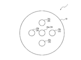
- FIG. 2 is a view of the medical device 1 as viewed from one side in the thickness direction A of the main body 10. As shown in FIG. 2, a plurality of second cylindrical portions 20b are arranged around the first cylindrical portion 20a.
- Examples of the material of the cylindrical portion 20 include biodegradable polymers.
- the biodegradable polymer as the material of the cylindrical portion 20 can be the same as the biodegradable polymer as the material of the main body portion 10.
- FIG. 3 is a flowchart showing a method of administering the stored item X using the medical device 1.
- FIG. 4 is a view showing a state in which the medical instrument 1 is placed on the outer wall of the heart 100. As shown in FIG. 4, the medical instrument 1 is placed in a state where the tubular portion 20 is punctured from the epicardium 110 as the outer wall of the heart 100 to the myocardium 120. At this time, the opening 22 of the cylindrical portion 20 is left in the myocardium 120.
- the tubular portion 20 is prevented from moving in a direction opposite to the projecting direction B by the return portion 23 from the tubular portion 20 punctured from the outer wall of the heart 100. Accordingly, the tubular portion 20 is prevented from coming off from the outer wall of the heart 100 due to pulsation or the like, and the indwelling state of the medical instrument 1 is stabilized.
- the main body 10 may be fixed to the heart 100.
- a technique for fixing the main body part 10 to the heart 100 for example, a technique in which an adhesive such as fibrin glue is interposed between the bottom surface 12 of the main body part 10 and the epicardium 110 and bonded, for example, a technique of stitching the film 110 with a suture is used.
- the process of step S11 is also referred to as an “indwelling step”.
- the contents X of the main body 10 are discharged through the tubular portion 20 according to the pulsation and administered into the myocardium 120 (step S12). More specifically, the main body 10 is stretched or compressed along a direction different from the projecting direction B of the tubular portion 20 according to the pulsation due to the rhythmic expansion and contraction of the myocardium 120. Due to the positive pressure in the storage space 11 generated thereby, the stored item X in the storage space 11 is discharged from the opening 22 through the hollow portion 21 of the cylindrical portion 20 and is administered into the myocardium 120.
- FIG. 5 is a schematic view showing a state in which the medical device 1 administers the stored item X into the myocardium 120 according to the pulsation
- FIG. 5 (a) shows a state in which the main body portion 10 is expanded
- FIG. 5 (b). Indicates a state in which the main body 10 is compressed.
- FIG. 5A for example, when the epicardium 110 of the heart 100 expands due to the expansion of the myocardium 120, the main body 10 follows the expansion of the epicardium 110 and follows the width direction C of the main body 10. Stretch along. Thereby, the volume of the accommodation space 11 is reduced by compressing the main body portion 10 along the thickness direction A, and the accommodation space 11 becomes positive pressure. Therefore, the contents X in the accommodation space 11 become the cylindrical portion 20. And is administered to the myocardium 120.
- the width direction C of the main body portion 10 is a direction substantially orthogonal to the protruding direction B of the tubular portion 20.
- the main body 10 follows the compression of the epicardium 110, and the main body 10 Is compressed along the width direction C.
- the volume of the accommodation space 11 of the main body 10 is reduced and the accommodation space 11 becomes positive pressure, so that the contents X in the accommodation space 11 are discharged through the cylindrical portion 20 and administered to the myocardium 120.
- the plurality of cylindrical portions 20 include a plurality of cylindrical portions 20 (first cylindrical portion 20a and second cylindrical portion 20b) having different lengths. Therefore, as shown in FIG. 5A and FIG. 5B, even if the thickness of the myocardium 120 varies from site to site, it is possible to simultaneously administer the contained X to a position at a certain percentage depth in the myocardium 120. .
- a plurality of second cylindrical portions 20b having a longer length than the first cylindrical portion 20a are arranged around the first cylindrical portion 20a. Therefore, as shown in FIGS. 5A and 5B, for example, when the medical device 1 is placed immediately above the infarcted region 121 of the myocardium 120, the central region where the infarct is strong and the myocardium 120 is thinned.
- the container X from the first cylindrical part 20a is administered shallower, and the container X from the second cylindrical part 20b is provided in a peripheral region where the degree of infarction is weak and the thickness of the myocardium 120 is relatively maintained. Will be administered deeper. Thereby, the container X can be effectively administered with respect to the myocardium 120 from which thickness changes with site
- the process of step S12 is also referred to as “administration step”.
- step S13 The main body 10 undergoes volume reduction deformation in accordance with the discharge of the contents X in the administration step (step S13).
- the volume of the storage space 11 of the main body 10 is reduced by the volume of the discharged stored matter X every time the stored item X is discharged.
- the process of step S13 is also referred to as “volume reduction deformation step”.
- step S14 If it is still possible for the main body 10 to discharge the contents X (YES in step S14), the process returns to step S12 (administration step). On the other hand, when it is impossible for the main body 10 to discharge the contents X (NO in step S14), the process proceeds to step S15.
- the state in which the main body 10 cannot discharge the stored item X does not necessarily mean that the stored item X does not remain in the storage space 11, and the stored item X depends on the expansion and contraction of the main unit 10. Means that the stored item X is discharged from the storage space 11 to the extent that is not discharged.
- step S14 the process of step S12 (administration step) and the process of step S13 (volume reduction deformation step) are repeated.
- step S12 administration step
- step S13 volume reduction deformation step
- the main body 10 discharges the contents X according to the pulsation, and deforms and deforms according to the discharge of the contents X. Therefore, the medical device 1 continuously stores the contents X in the myocardium 120. Can be administered.
- the main body portion 10 follows the stretch of the epicardium 110 along the width direction C of the main body portion 10 accordingly.
- step S16 To expand (step S16).
- the volume of the accommodation space 11 is reduced by compressing the main body portion 10 along the thickness direction A, and the stored matter X is discharged by the expansion and contraction of the main body portion 10 due to pulsation, so that the disease state deteriorates.
- the administration of the contents X to the myocardium 120 can be resumed (step S12).
- the administration of the contained material X is terminated. Then, it is preferable that the medical worker removes the medical instrument 1 from the living body.
- the medical instrument 1 is naturally decomposed in the body, and thus the medical instrument 1 is extracted. There is no need.
- the present disclosure is not limited to the configuration of the above-described embodiment, and can be realized by various configurations without departing from the content described in the claims.
- the plurality of tubular portions 20 may include tubular portions 20 having various lengths in addition to the first tubular portion 20a and the second tubular portion 20b.
- the some cylindrical part 20 contains the cylindrical part 20 from which length differs as above-mentioned, all may be comprised by the cylindrical part 20 of the same length.
- the medical device 1 preferably includes a plurality of cylindrical portions 20, but may include only one cylindrical portion 20.
- the opening 22 of the cylindrical portion 20 has been described as being partitioned by the distal end 27, but is not limited to such a configuration, and the medical device 1 is positioned in the myocardium while being placed on the outer wall of the heart. What is necessary is just to be divided in the side surface of the front-end
- the present disclosure relates to a medical device and a method for administering a contained item using the medical device.
Landscapes
- Health & Medical Sciences (AREA)
- Engineering & Computer Science (AREA)
- Animal Behavior & Ethology (AREA)
- Anesthesiology (AREA)
- Biomedical Technology (AREA)
- Heart & Thoracic Surgery (AREA)
- Hematology (AREA)
- Life Sciences & Earth Sciences (AREA)
- General Health & Medical Sciences (AREA)
- Public Health (AREA)
- Veterinary Medicine (AREA)
- Medical Informatics (AREA)
- Dermatology (AREA)
- Vascular Medicine (AREA)
- Materials For Medical Uses (AREA)
Abstract
医療器具は、収容空間を区画する本体部と、前記本体部から突設されている筒状部と、を備え、前記本体部が、前記筒状部の突設方向とは異なる方向に沿う伸張又は圧縮によって生じる前記収容空間内の正圧によって、前記収容空間内の収容物を前記筒状部を通じて排出する。
Description
本開示は、医療器具及びこの医療器具を用いた収容物の投与方法に関する。
従来、心筋梗塞などの心疾患に対して、薬物等を心筋に直接投与して治療することが行われている。例えば、特許文献1には、所定の心臓状況を示す生理的信号を検知するセンサと、化学作用物質(薬物)を心筋等に放出する薬物送出デバイスと、検知された生理的信号に基づいて化学作用物質の放出を制御するコントローラとを備える、埋め込み可能な薬物送出デバイスが開示されている。特許文献1に開示された薬物送出デバイスによれば、心臓状況に基づいて薬物の放出を制御するので、薬物を持続的に心筋に投与することができる。
しかしながら、特許文献1に開示された上述の薬物送出デバイスでは、生理的信号を検知するセンサや、化学物質の放出を制御するコントローラ等の電子回路が必要であるという点において構成が複雑化しやすいという問題があった。
本開示の目的は、上記問題に鑑み、電子回路を要することなく、細胞や薬液等の収容物を持続的に心筋に投与することができる医療器具及びこの医療器具を用いた収容物の投与方法を提供することである。
本発明の第1の態様としての医療器具は、収容空間を区画する本体部と、前記本体部から突設されている筒状部と、を備え、前記本体部が、前記筒状部の突設方向とは異なる方向に沿う伸張又は圧縮によって生じる前記収容空間内の正圧によって、前記収容空間内の収容物を前記筒状部を通じて排出する。
本発明の一実施形態としての医療器具は、前記本体部が、前記収容物の排出に応じて減容変形する。
本発明の一実施形態としての医療器具は、前記本体部は扁平形状を有し、前記筒状部が、前記本体部の厚み方向に向かって突設されている。
本発明の一実施形態としての医療器具は、前記筒状部を複数備え、前記複数の筒状部が、前記本体部から前記厚み方向の一方に向かって突設されている。
本発明の一実施形態としての医療器具は、前記複数の筒状部が、第1筒状部と、前記第1筒状部よりも長さが長い第2筒状部とを含む。
本発明の一実施形態としての医療器具は、前記第2筒状部が、前記第1筒状部の周囲に複数配置されている。
本発明の一実施形態としての医療器具は、前記筒状部が、前記突設方向の逆方向への移動を妨げる返し部を外面に有する。
本発明の一実施形態としての医療器具は、前記筒状部が生分解性である。
本発明の第2の態様としての投与方法は、収容空間を区画する本体部と、前記本体部から突設されている筒状部とを備える医療器具を、前記筒状部が心臓の外壁から心筋に至るまで穿刺して留置するステップと、前記本体部が、拍動に応じて前記筒状部の突設方向とは異なる方向に沿う伸張又は圧縮によって生じる前記収容空間内の正圧によって、前記収容空間内の収容物を前記筒状部を通じて前記心筋内に投与するステップと、を含む。
本開示の医療器具及び投与方法によれば、電子回路を要することなく、細胞や薬液等の収容物を持続的に心筋に投与することができる。
以下、一実施形態に係る医療器具及びこの医療器具を用いた収容物の投与方法について、図面を参照して説明する。各図において共通の部材には、同一の符号を付している。
図1は、一実施形態に係る医療器具1を示す縦断面図である。
図1に示すように、医療器具1は、本体部10と、複数の筒状部20とを備える。医療器具1は、心臓の外壁に留置して、治療として細胞や薬液等を心筋に投与するために用いられる。
本体部10は、扁平形状を有し、内部に収容空間11を区画している。収容空間11には、収容物Xが収容されている。収容物Xは、心疾患等を治療するために心筋内に投与されるものであり、任意の治療物質を用いることができる。治療物質としては、細胞の補充、血管新生誘導、心臓壁補強、足場材料、またはアポトーシス・ネクローシスの予防による組織修復あるいは再生などの治療効果が得られるものが挙げられ、例えば、細胞、薬液又はポリマー等である。収容物Xとしての細胞は、例えば、生理食塩水等の液体中に分散した細胞懸濁液として収容空間11に収容される。
収容物Xとしての細胞は、例えば、接着細胞(付着性細胞)を含む。接着細胞は、例えば、接着性の体細胞(例えば、心筋細胞、線維芽細胞、上皮細胞、内皮細胞、肝細胞、膵細胞、腎細胞、副腎細胞、歯根膜細胞、歯肉細胞、骨膜細胞、皮膚細胞、滑膜細胞、軟骨細胞など)及び幹細胞(例えば、筋芽細胞、心臓幹細胞などの組織幹細胞、胚性幹細胞、iPS(induced pluripotent stem)細胞などの多能性幹細胞、間葉系幹細胞等)などを含む。体細胞は、幹細胞、特にiPS細胞から分化させたものであってもよい。収容物Xとしての細胞の非限定例としては、例えば、筋芽細胞(例えば、骨格筋芽細胞など)、間葉系幹細胞(例えば、骨髄、脂肪組織、末梢血、皮膚、毛根、筋組織、子宮内膜、胎盤、臍帯血由来のものなど)、心筋細胞、線維芽細胞、心臓幹細胞、胚性幹細胞、iPS細胞、滑膜細胞、軟骨細胞、上皮細胞(例えば、口腔粘膜上皮細胞、網膜色素上皮細胞、鼻粘膜上皮細胞など)、内皮細胞(例えば、血管内皮細胞など)、肝細胞(例えば、肝実質細胞など)、膵細胞(例えば、膵島細胞など)、腎細胞、副腎細胞、歯根膜細胞、歯肉細胞、骨膜細胞、皮膚細胞等が挙げられる。
収容物Xとしての薬剤は、例えば、タンパク質、プラスミド、遺伝子、成長因子、化学誘因物質、合成ポリペプチド、種々の医薬組成物等が挙げられ、さらには他の治療的に有益な物質を単独で、または任意の組合せで含むこともできる。
収容物Xとしてのポリマーは、注入可能な生体適合性を有する単一成分または多成分材料、ポリマーベースのビーズ、ポリマーヒドロゲル、フィブリン接着剤、コラーゲン、アルギン酸塩、ポリエチレングリコールなどの合成高分子材料、およびキトサン等が挙げられる。
本体部10は、伸縮性を有する。本体部10の材料は、例えば、ゴム材などの軟質材料や生分解性ポリマーが挙げられる。
本体部10の材料としての軟質材料は、特に限定されないが、シリコーンゴム、シリコン樹脂、天然ゴム、ブチルゴム、イソプレンゴム、ブタジエンゴム、スチレンブタジエンゴム、スチレンエチレンブチレンスチレンゴム、エチレンプロピレンゴム、アクリロニトリルブタジエンゴム、フッ素ゴム、ウレタンゴム、多硫化ゴム、塩素化ブチルゴム等であることが好ましい。
本体部10の材料としての生分解性ポリマーは、特に限定されないが、ポリ乳酸、ポリグリコール酸、ポリカプロラクトン、ポリヒドロキシ酪酸、セルロース、ポリヒドロキシブチレイト吉草酸、およびポリオルソエステルからなる群から選択される少なくとも1つ、もしくは、これらの共重合体(乳酸-カプロラクトンの共重合体、グリコリド-カプロラクトン共重合体等)、混合物、または複合物等であることが好ましい。
筒状部20は、本体部10から突設されている。より詳細には、複数の筒状部20は、それぞれ、扁平形状を有する本体部10の厚み方向Aの一方(図1の下方)に向かって突設されている。以下、筒状部20が突設される方向を突設方向Bと記載する。また、筒状部20は、内部に中空部21を区画している。中空部21は、筒状部20の基端26で本体部10の収容空間11に連通し、筒状部20の先端27で開口22を通じて外部に連通している。
筒状部20の先端27は、心臓の外壁から心筋に至るまで、突設方向Bへの穿刺が可能な程度に鋭利に形成されている。また、筒状部20は、筒状部20が突設方向Bの逆方向へ移動することを妨げる返し部23を外面に有している。図1に示すように、筒状部20は、外径が突設方向Bに沿って段差面24を介して拡径し、さらに突設方向Bに沿って漸減する形状を有している。本実施形態の返し部23は、この段差面24により構成されている。
図1に示すように、複数の筒状部20は、第1筒状部20aと、第1筒状部20aよりも長さが長い第2筒状部20bとを含む。図2は、医療器具1を本体部10の厚み方向Aの一方側から見た図である。図2に示すように、第2筒状部20bは、第1筒状部20aの周囲に複数配置されている。
筒状部20の材料は、例えば、生分解性ポリマーが挙げられる。筒状部20の材料としての生分解性ポリマーは、本体部10の材料としての生分解性ポリマーと同様とすることができる。
以下、医療器具1を用いた収容物Xの投与方法について説明する。図3は、医療器具1を用いた収容物Xの投与方法を示すフローチャートである。
まず、医療従事者が、医療器具1を患者等の生体の心臓の外壁に留置する(ステップS11)。図4は、医療器具1を心臓100の外壁に留置した状態を示す図である。図4に示すように、医療器具1は、筒状部20が心臓100の外壁としての心外膜110から心筋120に至るまで穿刺した状態で、留置される。このとき、筒状部20の開口22は、心筋120内に留置される。
また、筒状部20は、図4に示すように、返し部23により、心臓100の外壁から穿刺された筒状部20が突設方向Bの逆方向へ移動することが妨げられる。従って、拍動等によって筒状部20が心臓100の外壁から抜けることが抑制され、医療器具1の留置状態が安定する。
医療器具1の留置状態をより安定させるために、本体部10を心臓100に固定させてもよい。本体部10を心臓100に固定させる手法としては、例えば、フィブリン糊などの接着剤を本体部10の底面12と心外膜110との間に介在させて接着する手法、本体部10と心外膜110とを縫合糸を用いて縫合する手法等が挙げられる。以下、ステップS11の工程を、「留置ステップ」とも記載する。
医療器具1は、留置ステップによって心臓100の外壁に留置されると、拍動に応じて本体部10の収容物Xを筒状部20を通じて排出し、心筋120内に投与する(ステップS12)。より詳細には、本体部10は、心筋120の律動的な膨張及び収縮による拍動に応じて、筒状部20の突設方向Bとは異なる方向に沿って伸張し、又は圧縮される。これにより生じる収容空間11内の正圧によって、収容空間11内の収容物Xが筒状部20の中空部21を通じて開口22から排出され、心筋120内に投与される。
図5は、医療器具1が拍動に応じて収容物Xを心筋120内に投与する様子を示す概略図であり、図5(a)は本体部10が伸張した状態、図5(b)は本体部10が圧縮された状態を示す。図5(a)に示すように、例えば心筋120が膨張することで心臓100の心外膜110が伸張すると、本体部10が心外膜110の伸張に追従して本体部10の幅方向Cに沿って伸張する。これにより、本体部10が厚み方向Aに沿って圧縮されることで収容空間11の体積が減少し、収容空間11が正圧となるため、収容空間11内の収容物Xが筒状部20を通じて排出され、心筋120に投与される。本体部10の幅方向Cは、筒状部20の突設方向Bとは略直交する方向である。
また、図5(b)に示すように、例えば心筋120が収縮することで心臓100の心外膜110が圧縮されると、本体部10が心外膜110の圧縮に追従して本体部10の幅方向Cに沿って圧縮される。これにより、本体部10の収容空間11の体積が減少し、収容空間11が正圧となるため、収容空間11内の収容物Xが筒状部20を通じて排出され、心筋120に投与される。
ところで、複数の筒状部20は、上述の通り、長さの異なる複数の筒状部20(第1筒状部20a及び第2筒状部20b)を含む。従って、図5(a)及び図5(b)に示すように、心筋120の厚みが部位で異なっていても、心筋120における一定割合深さの位置に同時に収容物Xを投与することができる。
また、上述の通り、第1筒状部20aの周囲に、第1筒状部20aよりも長さが長い第2筒状部20bが複数配置されている。従って、図5(a)及び図5(b)に示すように、例えば心筋120の梗塞部位121の直上に医療器具1を留置した場合、梗塞の程度が強く心筋120が薄くなっている中心部位には第1筒状部20aからの収容物Xがより浅く投与され、梗塞の程度が弱く心筋120の厚みが比較的保たれている周辺部位には第2筒状部20bからの収容物Xがより深くに投与されることになる。これにより梗塞の進行によって厚みが部位により異なる心筋120に対して収容物Xを効果的に投与することができる。以下、ステップS12の工程を、「投与ステップ」とも記載する。
本体部10は、投与ステップによる収容物Xの排出に応じて減容変形する(ステップS13)。換言すると、本体部10の収容空間11の体積は、収容物Xが排出される度に、排出された収容物Xの体積の分だけ減少する。以下、ステップS13の工程を、「減容変形ステップ」とも記載する。
本体部10が収容物Xを排出することがまだ可能な場合(ステップS14のYES)、ステップS12の工程(投与ステップ)に戻る。一方、本体部10が収容物Xを排出することが不可能な場合(ステップS14のNO)、ステップS15の工程に進む。本体部10が収容物Xを排出することが不可能な状態とは、必ずしも収容空間11に収容物Xが残存していないことを意味せず、本体部10の伸張及び収縮によっては収容物Xが排出されない程度に収容空間11から収容物Xが排出された状態を意味する。
このように、本体部10が収容物Xを排出することが可能である限り(ステップS14のYES)、ステップS12の工程(投与ステップ)とステップS13の工程(減容変形ステップ)とが繰り返される。これにより、本体部10は、拍動に応じて収容物Xを排出すると共に、収容物Xの排出に応じて減容変形するため、医療器具1は、収容物Xを持続的に心筋120内に投与することができる。
また、心筋梗塞の病態悪化によって心臓100の伸張が進行した場合は(ステップS15のYES)、それに伴い、本体部10が心外膜110の伸張に追従して本体部10の幅方向Cに沿って伸張する(ステップS16)。これにより、本体部10が厚み方向Aに沿って圧縮されることで収容空間11の体積が減少し、拍動による本体部10の伸張及び収縮によって収容物Xが排出されるため、病態の悪化に対応して、収容物Xの心筋120への投与を再開することができる(ステップS12)。
本体部10が収容物Xを排出することが不可能となり(ステップS14のNO)、病態悪化による心臓100の伸張の進行もない場合(ステップS15のNO)、収容物Xの投与を終了する。その後、医療従事者は、医療器具1を生体から摘出することが好ましい。医療器具1を構成する本体部10及び筒状部20の材料として、上述の生分解性ポリマーを用いた場合には、医療器具1は自然に体内で分解されるため、医療器具1を摘出する必要がない。
本開示は、上述した実施形態の構成に限定されるものではなく、特許請求の範囲で記載された内容を逸脱しない範囲で、様々な構成により実現することが可能である。例えば、複数の筒状部20は、第1筒状部20a及び第2筒状部20b以外にも、様々な長さを有する筒状部20を含んでもよい。また、複数の筒状部20は、上述の通り、長さの異なる筒状部20を含むことが好ましいが、全て同じ長さの筒状部20で構成されていてもよい。さらに、医療器具1は、上述の通り、複数の筒状部20を備えることが好ましいが、筒状部20を1つだけ備えてもよい。
また、筒状部20の開口22は、先端27に区画されるとして説明したが、このような構成には限定されず、医療器具1が心臓の外壁に留置された状態で心筋内に位置すればよく例えば、先端部の側面に区画されていてもよい。
本開示は、医療器具及びこの医療器具を用いた収容物の投与方法に関する。
1 医療器具
10 本体部
11 収容空間
12 底面
20 筒状部
20a 第1筒状部
20b 第2筒状部
21 中空部
22 開口
23 返し部
24 段差面
26 基端
27 先端
100 心臓
110 心外膜(外壁)
120 心筋
130 心内膜
A 本体部の厚み方向
B 筒状部の突設方向
C 本体部の幅方向
X 収容物
10 本体部
11 収容空間
12 底面
20 筒状部
20a 第1筒状部
20b 第2筒状部
21 中空部
22 開口
23 返し部
24 段差面
26 基端
27 先端
100 心臓
110 心外膜(外壁)
120 心筋
130 心内膜
A 本体部の厚み方向
B 筒状部の突設方向
C 本体部の幅方向
X 収容物
Claims (9)
- 収容空間を区画する本体部と、
前記本体部から突設されている筒状部と、を備え、
前記本体部は、前記筒状部の突設方向とは異なる方向に沿う伸張又は圧縮によって生じる前記収容空間内の正圧によって、前記収容空間内の収容物を前記筒状部を通じて排出する、医療器具。 - 前記本体部は、前記収容物の排出に応じて減容変形する、請求項1に記載の医療器具。
- 前記本体部は扁平形状を有し、
前記筒状部は、前記本体部の厚み方向に向かって突設されている、請求項1又は2に記載の医療器具。 - 前記筒状部を複数備え、
前記複数の筒状部は、前記本体部から前記厚み方向の一方に向かって突設されている、請求項3に記載の医療器具。 - 前記複数の筒状部は、第1筒状部と、前記第1筒状部よりも長さが長い第2筒状部とを含む、請求項4に記載の医療器具。
- 前記第2筒状部は、前記第1筒状部の周囲に複数配置されている、請求項5に記載の医療器具。
- 前記筒状部は、前記突設方向の逆方向への移動を妨げる返し部を外面に有する、請求項1から6のいずれか一項に記載の医療器具。
- 前記筒状部は、生分解性である、請求項1から7のいずれか一項に記載の医療器具。
- 収容空間を区画する本体部と、前記本体部から突設されている筒状部とを備える医療器具を、前記筒状部が心臓の外壁から心筋に至るまで穿刺して留置するステップと、
前記本体部が、拍動に応じて前記筒状部の突設方向とは異なる方向に沿う伸張又は圧縮によって生じる前記収容空間内の正圧によって、前記収容空間内の収容物を前記筒状部を通じて前記心筋内に投与するステップと、
を含む投与方法。
Applications Claiming Priority (2)
| Application Number | Priority Date | Filing Date | Title |
|---|---|---|---|
| JP2016-185364 | 2016-09-23 | ||
| JP2016185364 | 2016-09-23 |
Publications (1)
| Publication Number | Publication Date |
|---|---|
| WO2018056403A1 true WO2018056403A1 (ja) | 2018-03-29 |
Family
ID=61689942
Family Applications (1)
| Application Number | Title | Priority Date | Filing Date |
|---|---|---|---|
| PCT/JP2017/034331 Ceased WO2018056403A1 (ja) | 2016-09-23 | 2017-09-22 | 医療器具及び投与方法 |
Country Status (1)
| Country | Link |
|---|---|
| WO (1) | WO2018056403A1 (ja) |
Citations (3)
| Publication number | Priority date | Publication date | Assignee | Title |
|---|---|---|---|---|
| JP2005087520A (ja) * | 2003-09-18 | 2005-04-07 | Terumo Corp | 薬液注入装置 |
| JP2015226649A (ja) * | 2014-05-30 | 2015-12-17 | 株式会社ワークス | マイクロニードル構造体及びマイクロニードル構造体の製造方法 |
| JP2016505325A (ja) * | 2012-12-18 | 2016-02-25 | アボット、カーディオバスキュラー、システムズ、インコーポレーテッドAbbott Cardiovascular Systems Inc. | 圧電医療インプラント |
-
2017
- 2017-09-22 WO PCT/JP2017/034331 patent/WO2018056403A1/ja not_active Ceased
Patent Citations (3)
| Publication number | Priority date | Publication date | Assignee | Title |
|---|---|---|---|---|
| JP2005087520A (ja) * | 2003-09-18 | 2005-04-07 | Terumo Corp | 薬液注入装置 |
| JP2016505325A (ja) * | 2012-12-18 | 2016-02-25 | アボット、カーディオバスキュラー、システムズ、インコーポレーテッドAbbott Cardiovascular Systems Inc. | 圧電医療インプラント |
| JP2015226649A (ja) * | 2014-05-30 | 2015-12-17 | 株式会社ワークス | マイクロニードル構造体及びマイクロニードル構造体の製造方法 |
Similar Documents
| Publication | Publication Date | Title |
|---|---|---|
| US12390597B2 (en) | Track-indexed syringe | |
| Ma et al. | Multifaceted design and emerging applications of tissue adhesives | |
| JP6636507B2 (ja) | 液体並びに粉末止血剤及びシーラントを共送達するための方法及び装置 | |
| JP4236874B2 (ja) | 移植装置 | |
| US8137354B2 (en) | Localized cartilage defect therapy | |
| US20070093748A1 (en) | Methods and systems for treating injured cardiac tissue | |
| US8858593B2 (en) | Emergency wound treatment device and method | |
| US20110208238A1 (en) | Applicator delivery tip extension | |
| US20210322652A1 (en) | Injectable hydrogels for local delivery to the heart | |
| JP2018501011A (ja) | 接着剤塗布器具 | |
| JPWO2017090254A1 (ja) | マイクロニードル及びその製造方法 | |
| US10695116B2 (en) | Reduced extravasation of bone cement | |
| JP7037026B2 (ja) | 麻酔シリンジ本体用のキャップ及びアプリケータ | |
| JP2009515565A (ja) | 生体材料を心臓に供給する装置および方法 | |
| US20120150097A1 (en) | Medical instrument for micro-invasive applications | |
| WO2023056588A1 (en) | Systems, devices and methods of using hydraulic forces for delivering flowable, therapeutic compositions to surgical sites | |
| KR101680820B1 (ko) | 치료용 니들 부재, 이를 구비하는 주사용 기구 및 이를 이용한 치료 방법 | |
| EP2007403A2 (en) | Methods and systems for treating injured cardiac tissue | |
| CN119367025B (zh) | 股骨近端髓内钉 | |
| JP7370981B2 (ja) | 生体内留置物の製造方法および留置システム | |
| JP2021530300A (ja) | 滅菌内部を有する針アセンブリ | |
| US20250091286A1 (en) | In vivo 3d bioprinting device and method | |
| Ambiga et al. | Future Trends in Biomedical Applications | |
| JP2023034852A (ja) | キャップ部を備えた組織中の目的部位に細胞を投与するための医療機器 | |
| WO2022010703A1 (en) | Improved hemostatic material and device for achieving durable hemostasis of a bleeding biopsy tract |
Legal Events
| Date | Code | Title | Description |
|---|---|---|---|
| 121 | Ep: the epo has been informed by wipo that ep was designated in this application |
Ref document number: 17853171 Country of ref document: EP Kind code of ref document: A1 |
|
| NENP | Non-entry into the national phase |
Ref country code: DE |
|
| 122 | Ep: pct application non-entry in european phase |
Ref document number: 17853171 Country of ref document: EP Kind code of ref document: A1 |
|
| NENP | Non-entry into the national phase |
Ref country code: JP |