WO2018056155A1 - Information processing device, image generation method and head-mounted display - Google Patents
Information processing device, image generation method and head-mounted display Download PDFInfo
- Publication number
- WO2018056155A1 WO2018056155A1 PCT/JP2017/033190 JP2017033190W WO2018056155A1 WO 2018056155 A1 WO2018056155 A1 WO 2018056155A1 JP 2017033190 W JP2017033190 W JP 2017033190W WO 2018056155 A1 WO2018056155 A1 WO 2018056155A1
- Authority
- WO
- WIPO (PCT)
- Prior art keywords
- image
- images
- viewpoint
- user
- line
- Prior art date
Links
Images


Classifications
-
- H—ELECTRICITY
- H04—ELECTRIC COMMUNICATION TECHNIQUE
- H04N—PICTORIAL COMMUNICATION, e.g. TELEVISION
- H04N13/00—Stereoscopic video systems; Multi-view video systems; Details thereof
- H04N13/10—Processing, recording or transmission of stereoscopic or multi-view image signals
- H04N13/106—Processing image signals
- H04N13/122—Improving the 3D impression of stereoscopic images by modifying image signal contents, e.g. by filtering or adding monoscopic depth cues
-
- G—PHYSICS
- G02—OPTICS
- G02B—OPTICAL ELEMENTS, SYSTEMS OR APPARATUS
- G02B27/00—Optical systems or apparatus not provided for by any of the groups G02B1/00 - G02B26/00, G02B30/00
- G02B27/0093—Optical systems or apparatus not provided for by any of the groups G02B1/00 - G02B26/00, G02B30/00 with means for monitoring data relating to the user, e.g. head-tracking, eye-tracking
-
- G—PHYSICS
- G02—OPTICS
- G02B—OPTICAL ELEMENTS, SYSTEMS OR APPARATUS
- G02B27/00—Optical systems or apparatus not provided for by any of the groups G02B1/00 - G02B26/00, G02B30/00
- G02B27/01—Head-up displays
- G02B27/017—Head mounted
-
- G—PHYSICS
- G06—COMPUTING; CALCULATING OR COUNTING
- G06F—ELECTRIC DIGITAL DATA PROCESSING
- G06F3/00—Input arrangements for transferring data to be processed into a form capable of being handled by the computer; Output arrangements for transferring data from processing unit to output unit, e.g. interface arrangements
- G06F3/14—Digital output to display device ; Cooperation and interconnection of the display device with other functional units
- G06F3/147—Digital output to display device ; Cooperation and interconnection of the display device with other functional units using display panels
-
- G—PHYSICS
- G06—COMPUTING; CALCULATING OR COUNTING
- G06T—IMAGE DATA PROCESSING OR GENERATION, IN GENERAL
- G06T19/00—Manipulating 3D models or images for computer graphics
-
- G—PHYSICS
- G09—EDUCATION; CRYPTOGRAPHY; DISPLAY; ADVERTISING; SEALS
- G09G—ARRANGEMENTS OR CIRCUITS FOR CONTROL OF INDICATING DEVICES USING STATIC MEANS TO PRESENT VARIABLE INFORMATION
- G09G5/00—Control arrangements or circuits for visual indicators common to cathode-ray tube indicators and other visual indicators
- G09G5/36—Control arrangements or circuits for visual indicators common to cathode-ray tube indicators and other visual indicators characterised by the display of a graphic pattern, e.g. using an all-points-addressable [APA] memory
-
- H—ELECTRICITY
- H04—ELECTRIC COMMUNICATION TECHNIQUE
- H04N—PICTORIAL COMMUNICATION, e.g. TELEVISION
- H04N13/00—Stereoscopic video systems; Multi-view video systems; Details thereof
-
- H—ELECTRICITY
- H04—ELECTRIC COMMUNICATION TECHNIQUE
- H04N—PICTORIAL COMMUNICATION, e.g. TELEVISION
- H04N13/00—Stereoscopic video systems; Multi-view video systems; Details thereof
- H04N13/10—Processing, recording or transmission of stereoscopic or multi-view image signals
-
- H—ELECTRICITY
- H04—ELECTRIC COMMUNICATION TECHNIQUE
- H04N—PICTORIAL COMMUNICATION, e.g. TELEVISION
- H04N13/00—Stereoscopic video systems; Multi-view video systems; Details thereof
- H04N13/10—Processing, recording or transmission of stereoscopic or multi-view image signals
- H04N13/106—Processing image signals
- H04N13/111—Transformation of image signals corresponding to virtual viewpoints, e.g. spatial image interpolation
- H04N13/117—Transformation of image signals corresponding to virtual viewpoints, e.g. spatial image interpolation the virtual viewpoint locations being selected by the viewers or determined by viewer tracking
-
- H—ELECTRICITY
- H04—ELECTRIC COMMUNICATION TECHNIQUE
- H04N—PICTORIAL COMMUNICATION, e.g. TELEVISION
- H04N13/00—Stereoscopic video systems; Multi-view video systems; Details thereof
- H04N13/10—Processing, recording or transmission of stereoscopic or multi-view image signals
- H04N13/106—Processing image signals
- H04N13/156—Mixing image signals
-
- H—ELECTRICITY
- H04—ELECTRIC COMMUNICATION TECHNIQUE
- H04N—PICTORIAL COMMUNICATION, e.g. TELEVISION
- H04N13/00—Stereoscopic video systems; Multi-view video systems; Details thereof
- H04N13/20—Image signal generators
-
- H—ELECTRICITY
- H04—ELECTRIC COMMUNICATION TECHNIQUE
- H04N—PICTORIAL COMMUNICATION, e.g. TELEVISION
- H04N13/00—Stereoscopic video systems; Multi-view video systems; Details thereof
- H04N13/20—Image signal generators
- H04N13/204—Image signal generators using stereoscopic image cameras
- H04N13/243—Image signal generators using stereoscopic image cameras using three or more 2D image sensors
-
- H—ELECTRICITY
- H04—ELECTRIC COMMUNICATION TECHNIQUE
- H04N—PICTORIAL COMMUNICATION, e.g. TELEVISION
- H04N13/00—Stereoscopic video systems; Multi-view video systems; Details thereof
- H04N13/20—Image signal generators
- H04N13/282—Image signal generators for generating image signals corresponding to three or more geometrical viewpoints, e.g. multi-view systems
-
- H—ELECTRICITY
- H04—ELECTRIC COMMUNICATION TECHNIQUE
- H04N—PICTORIAL COMMUNICATION, e.g. TELEVISION
- H04N13/00—Stereoscopic video systems; Multi-view video systems; Details thereof
- H04N13/30—Image reproducers
- H04N13/332—Displays for viewing with the aid of special glasses or head-mounted displays [HMD]
- H04N13/344—Displays for viewing with the aid of special glasses or head-mounted displays [HMD] with head-mounted left-right displays
-
- H—ELECTRICITY
- H04—ELECTRIC COMMUNICATION TECHNIQUE
- H04N—PICTORIAL COMMUNICATION, e.g. TELEVISION
- H04N13/00—Stereoscopic video systems; Multi-view video systems; Details thereof
- H04N13/30—Image reproducers
- H04N13/366—Image reproducers using viewer tracking
-
- H—ELECTRICITY
- H04—ELECTRIC COMMUNICATION TECHNIQUE
- H04N—PICTORIAL COMMUNICATION, e.g. TELEVISION
- H04N13/00—Stereoscopic video systems; Multi-view video systems; Details thereof
- H04N13/30—Image reproducers
- H04N13/366—Image reproducers using viewer tracking
- H04N13/383—Image reproducers using viewer tracking for tracking with gaze detection, i.e. detecting the lines of sight of the viewer's eyes
-
- G—PHYSICS
- G02—OPTICS
- G02B—OPTICAL ELEMENTS, SYSTEMS OR APPARATUS
- G02B27/00—Optical systems or apparatus not provided for by any of the groups G02B1/00 - G02B26/00, G02B30/00
- G02B27/01—Head-up displays
- G02B27/0101—Head-up displays characterised by optical features
- G02B2027/0132—Head-up displays characterised by optical features comprising binocular systems
- G02B2027/0134—Head-up displays characterised by optical features comprising binocular systems of stereoscopic type
-
- G—PHYSICS
- G02—OPTICS
- G02B—OPTICAL ELEMENTS, SYSTEMS OR APPARATUS
- G02B27/00—Optical systems or apparatus not provided for by any of the groups G02B1/00 - G02B26/00, G02B30/00
- G02B27/01—Head-up displays
- G02B27/0101—Head-up displays characterised by optical features
- G02B2027/0138—Head-up displays characterised by optical features comprising image capture systems, e.g. camera
-
- G—PHYSICS
- G09—EDUCATION; CRYPTOGRAPHY; DISPLAY; ADVERTISING; SEALS
- G09G—ARRANGEMENTS OR CIRCUITS FOR CONTROL OF INDICATING DEVICES USING STATIC MEANS TO PRESENT VARIABLE INFORMATION
- G09G2354/00—Aspects of interface with display user
Definitions
- the present invention relates to a technique for generating a parallax image to be displayed on a head-mounted display and / or a technique for displaying a parallax image on a head-mounted display.
- the head mounted display is mounted on the user's head to provide the user with a virtual reality (VR) world.
- VR virtual reality
- a technique for taking a panoramic photograph has become widespread, and by displaying the taken panoramic photograph image on the HMD, a user can feel as if he / she is in a real place.
- the HMD is provided with a display panel for the user's left eye and right eye, and a stereo stereoscopic view is realized by displaying a left eye image and a right eye image (parallax image) from each display panel.
- the left-eye virtual camera and the right-eye virtual camera are arranged in the game space to generate the left-eye and right-eye game images and output them from the respective display panels of the HMD.
- a content image as a material is generally captured using a stereo camera for stereo stereoscopic display.
- the subject is photographed using the stereo camera by photographing each time by rotating the left camera and the right camera horizontally by a predetermined amount from the fixed point in the up and down direction and the left and right direction. Therefore, when the user wearing the HMD swings his / her neck up / down or left / right, the horizontal height of both eyes of the user is uniform, so the parallax amount is constant based on the material of the stereo image.
- a parallax image can be generated.
- the present invention has been made in view of these problems, and an object of the present invention is to provide a technique for appropriately generating a parallax image to be displayed by an HMD and / or a technique for displaying a parallax image.
- an information processing apparatus includes a detection unit that detects a posture of a head-mounted display attached to a user's head, and a posture of the head-mounted display that is detected by the detection unit. And determining the binocular tilt angle, which is the angle between the line of sight of the user and the line connecting both eyes and the horizontal plane, and generating parallax images for the left and right eyes from a plurality of viewpoint images.
- An image specifying unit for specifying two images based on the user's line-of-sight direction and binocular tilt angle determined by the state determining unit, and generating a parallax image for the left eye and right eye from the two images specified by the image specifying unit
- an image providing unit that provides a parallax image generated by the image generating unit to a head mounted display.
- An information processing apparatus includes a detection unit that detects a posture of a head mounted display mounted on a user's head, and a user's line of sight according to the posture of the head mounted display detected by the detection unit.
- a state determining unit that determines a binocular tilt angle that is an angle between a direction and a line connecting both eyes and a horizontal plane, and a plurality of viewpoint images acquired in the first line-of-sight direction and / or a plurality of acquired in the second line-of-sight direction
- An image specifying unit for specifying at least two images used for generating a left-eye parallax image and a right-eye parallax image based on a user's line-of-sight direction and binocular tilt angle determined by the state determination unit, and an image specification
- An image generation unit that generates parallax images for the left eye and right eye from at least two images specified by the unit, and the parallax image generated by the image generation unit Comprising an image providing unit
- Still another aspect of the present invention relates to a head-mounted display including a left-eye display panel and a right-eye display panel.
- the head-mounted display is for the left eye and the right eye that are generated from two viewpoint images that are specified based on the viewing direction of the user who wears them and the binocular tilt angle that is the angle between the line connecting the eyes of the user and the horizontal plane.
- a control unit for receiving the image data for display on the left-eye display panel and the right-eye display panel.
- any combination of the above components, the expression of the present invention converted between a method, an apparatus, a system, a computer program, a recording medium on which the computer program is recorded so as to be readable, a data structure, and the like are also included in the present invention. It is effective as an embodiment of
- FIG. 1 It is a figure which shows the structural example of the information processing system in an Example. It is a figure which shows the structural example of a multiview camera.
- A)-(c) is a figure which shows the viewpoint image image
- D)-(e) is a figure which shows the viewpoint image image
- (A)-(b) is a figure which shows the state which has arrange
- (A)-(b) is a figure for demonstrating a binocular inclination angle. It is a figure which shows the intersection of a user's eyes
- (A)-(b) is a figure which shows the example of the image position for left eyes, and the image position for right eyes. It is a figure for demonstrating the gaze direction and angle of view of a multiview image. It is a figure which shows the relationship of the two-dimensional coordinate surface of a multiview image. It is a figure which shows an example of a user gaze direction. It is a figure for demonstrating the example which produces
- FIG. 1 shows a configuration example of an information processing system 1 in the embodiment.
- the information processing system 1 includes an information processing device 10, a head mounted display device (HMD) 100 that the user wears on the head, an input device 6 that the user operates with fingers, and an imaging device 7 that photographs the user wearing the HMD 100. And an output device 4 for displaying an image.
- HMD head mounted display device
- the information processing apparatus 10 includes a processing device 12, an output control device 14, and an image storage device 16.
- the processing device 12 is a terminal device that receives operation information of the input device 6 operated by a user and executes various applications.
- the processing device 12 and the input device 6 may be connected by a cable or may be connected by a known wireless communication protocol.
- the output control device 14 is a processing unit that outputs the image data generated by the processing device 12 to the HMD 100.
- the output control device 14 and the HMD 100 may be connected by a cable or may be connected by a known wireless communication protocol.
- the imaging device 7 is a stereo camera, which captures a user wearing the HMD 100 at a predetermined cycle and supplies the captured image to the processing device 12.
- the HMD 100 is provided with a marker (tracking LED) for tracking the user's head, and the processing device 12 detects the movement of the HMD 100 based on the position of the marker included in the captured image.
- the HMD 100 is equipped with posture sensors (acceleration sensor and gyro sensor), and the processing device 12 obtains sensor information detected by the posture sensor from the HMD 100, so that high accuracy can be achieved together with the use of the captured image of the marker. Execute tracking process.
- Various tracking methods have been proposed for tracking processing, and any tracking method may be employed as long as the processing device 12 can detect the movement of the HMD 100.
- the information processing system 1 implements a virtual reality (VR) application that provides a parallax image to the HMD 100. Since the user wears the HMD 100, the output device 4 is not necessarily required in the information processing system 1, but the output control device 14 or the processing device 12 may output the same image as the image displayed on the HMD 100 from the output device 4. Good. As a result, another user can view the image that the user is viewing on the HMD 100 on the output device 4. The HMD 100 outputs a parallax image, but the image output from the output device 4 may not be a parallax image.
- VR virtual reality
- the HMD 100 is a display device that displays an image on a display panel located in front of the user when the user wears the head.
- the HMD 100 separately displays a left-eye image on the left-eye display panel and a right-eye image on the right-eye display panel. These images are parallax images viewed from the left and right viewpoints, and realize stereoscopic viewing. Since the user views the display panel through the optical lens, the information processing apparatus 10 supplies the HMD 100 with parallax image data in which optical distortion caused by the lens is corrected. Either the processing device 12 or the output control device 14 may perform this optical distortion correction processing.
- the processing device 12, the output device 4, the input device 6, and the imaging device 7 may construct a conventional game system.
- the processing device 12 is a game device that executes a game
- the input device 6 is a device that supplies user operation information to the processing device 12 such as a game controller, a keyboard, a mouse, and a joystick.
- the function by the output control device 14 may be incorporated into the processing device 12 as a part of the VR application function. That is, the processing unit of the information processing apparatus 10 may be configured by one processing apparatus 12 or may be configured by the processing apparatus 12 and the output control apparatus 14. In the following, functions of the processing device 12 and the output control device 14 necessary for implementing the VR application will be collectively described as functions of the information processing device 10.
- the image storage device 16 stores in advance a plurality of viewpoint images acquired in the same line-of-sight direction from a plurality of viewpoint positions.
- the information processing apparatus 10 uses the at least two viewpoint images stored in the image storage device 16 to generate a left-eye parallax image and a right-eye parallax image, and supplies the parallax images to the HMD 100.
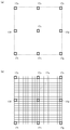
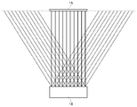
- FIG. 2 shows a configuration example of the multi-viewpoint camera 18 that captures a viewpoint image that is a material of the parallax image.
- the multi-viewpoint camera 18 has a plurality of cameras 19a to 19i arranged in a matrix on the same plane.
- the cameras 19a to 19i are arranged at regular intervals of three in the vertical and horizontal directions, but may have other arrangements.
- the cameras 19a to 19i are not distinguished, they are collectively referred to as “camera 19”.
- the camera 19 is composed of a solid-state image sensor such as a CMOS (Complementary Metal Oxide Semiconductor) or a CCD (Charge Coupled Device) sensor.
- CMOS Complementary Metal Oxide Semiconductor
- CCD Charge Coupled Device
- the optical axis (line-of-sight direction) of each camera 19 is set in a direction perpendicular to the front of the multi-view camera 18. That is, the optical axes of the plurality of cameras 19 are set in parallel with each other, and therefore, the two adjacent cameras 19 shoot a subject that is shifted by a distance (baseline length) between the cameras in the viewing direction parallel to each other.
- the multi-viewpoint camera 18 acquires a plurality of viewpoint images corresponding to the viewpoint positions of the plurality of cameras 19 by the plurality of cameras 19 capturing the subject at the same time.
- FIGS. 3A to 3E show viewpoint images 17 captured by the cameras 19.
- the left and right positions of the camera 19 are defined with reference to the direction from the camera 19 toward the subject (that is, the left and right positions shown in FIG. 2 are reversed).
- FIG. 3A shows a viewpoint image 17e photographed by a camera 19e located at the center of the multi-viewpoint camera 18.
- FIG. 3B shows a viewpoint image 17c photographed by the upper left camera 19c and a viewpoint image 17g photographed by the lower right camera 19g.
- FIG. 3C shows a viewpoint image 17a photographed by the upper right camera 19a and a viewpoint image 17i photographed by the lower left camera 19i.
- FIG. 3D shows a viewpoint image 17b photographed by the upper center camera 19b and a viewpoint image 17f photographed by the center left camera 19f.
- FIG. 3E shows a viewpoint image 17h photographed by the lower center camera 19h and a viewpoint image 17d photographed by the center right camera 19d.
- the multi-view camera 18 acquires a plurality of viewpoint images 17a to 17i at the same time.
- the distance between the cameras 19 that are adjacent vertically and horizontally is set to 20 mm, for example. Since the optical axes of the cameras 19 are parallel to each other, images taken by different cameras 19 are images taken from different viewpoint positions in the same photographing direction (gaze direction), and were photographed by the cameras 19 that are adjacent vertically and horizontally. The two images will have a 20 mm parallax.
- an interpolated image obtained by interpolating a plurality of viewpoint images 17 captured by the multi-view camera 18 is generated in advance so that the parallax image provided to the user moves smoothly in conjunction with the movement of the HMD 100 worn by the user.
- the interpolated image corresponds to a viewpoint image captured from a different viewpoint position in the same viewing direction as the viewing direction of the multi-view camera 18, and the viewpoint image 17 captured by the actual camera 19 is referred to as an “actual viewpoint image”.
- An interpolation image generated by interpolation processing from at least two real viewpoint images can be referred to as a “virtual viewpoint image”.
- the real viewpoint image interpolation process may be performed by the information processing apparatus 10, but may be performed, for example, by an image server that provides a content image and may be provided to the information processing apparatus 10.
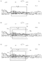
- FIG. 4A shows a state in which the real viewpoint image captured by the multi-viewpoint camera 18 is arranged on a virtual two-dimensional plane (two-dimensional coordinate plane).
- the camera position viewpoint position
- the interval baseline length
- the parallax between the viewpoint images 17 adjacent in the vertical and horizontal directions also on the two-dimensional coordinate plane shown in FIG. The quantity is expressed as 20 mm.
- FIG. 4B shows a state where an interpolation image (virtual viewpoint image) for interpolating between a plurality of real viewpoint images is arranged on a virtual two-dimensional coordinate plane.
- a plurality of virtual viewpoint images are generated between the plurality of viewpoint images 17 captured by the camera 19 so that the parallax amount between adjacent viewpoint images is 2 mm.
- FIG. 4B shows a state in which an interpolated image expressed by a thin line is generated between the viewpoint images 17 expressed by a thick line.
- the processing device 12 may generate an interpolated image by a known algorithm. Hereinafter, an example of the interpolation process will be shown.
- the processing device 12 acquires depth information (depth information) of a subject image based on a plurality of real viewpoint images.
- the depth information is acquired by performing, for example, a stereo matching process.
- Stereo matching is a technique for obtaining three-dimensional depth information using this shift, and the processing device 12 generates a plurality of interpolated images between the actual viewpoint images based on the plurality of actual viewpoint images and the depth information. And stored in the image storage device 16.
- the interpolation image in the upper right area surrounded by the viewpoint images 17a, 17b, 17e, and 17d will be described.
- Nine virtual viewpoint images acquired when the viewpoint position is moved by 2 mm in the horizontal direction are generated between the viewpoint image 17a and the viewpoint image 17b.
- nine virtual viewpoint images acquired when the viewpoint position is moved by 2 mm in the horizontal direction are generated between the viewpoint image 17d and the viewpoint image 17e.
- 11 viewpoint images are arranged from the viewpoint image 17a to the viewpoint image 17b, and 11 viewpoint images are arranged from the viewpoint image 17d to the viewpoint image 17e.
- nine virtual viewpoint images acquired when the viewpoint position is moved by 2 mm in the vertical direction are generated for each column.
- a multi-viewpoint image in which the parallax amount between the viewpoint images adjacent vertically and horizontally in the upper right area is 2 mm is configured.
- each viewpoint image is stored in association with the viewpoint position.
- the viewpoint position is set as a coordinate value on a virtual two-dimensional coordinate, and this coordinate value is used when calculating an actual distance.
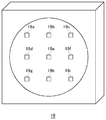
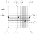
- FIG. 5 shows an example of coordinate values of viewpoint positions associated with viewpoint images.
- the viewpoint position of the viewpoint image 17e is set to the origin (0, 0) for convenience.
- the viewpoint position of the viewpoint image 17a is expressed as (10, 10)
- the viewpoint position of the viewpoint image 17h is expressed as (0, -10).
- the viewpoint position of the viewpoint image 17m is expressed as (6, -4)
- the viewpoint position of the viewpoint image 17n is expressed as (-5,5).
- one graduation (one coordinate value) on the x-axis and the y-axis corresponds to 2 mm.
- any two viewpoint positions are (x1, y1) and (x2, y2), respectively, the distance between the two viewpoint positions is It is expressed.
- the method of expressing the viewpoint position on the two-dimensional coordinate plane is an example, and the viewpoint position may be managed so that the distance between the two viewpoint positions can be calculated.
- a multi-viewpoint image in which the parallax amount between the viewpoint images adjacent in the vertical and horizontal directions is 2 mm may be generated by interpolation processing, but may be acquired by actually shooting.
- a single camera 19 is moved within the range of 40 mm in length and 40 mm in the vertical and horizontal directions in the same line-of-sight direction, and by taking a picture every time it moves, a total of 441 viewpoints in which the parallax amount between adjacent viewpoint images is 2 mm.
- An image may be acquired.
- a plurality of multi-viewpoint images may be acquired so as to be spatially continuous in the horizontal direction and stored in the storage device 16. By connecting a plurality of types of multi-viewpoint images, a panoramic image in all right and left directions is formed.
- the information processing apparatus 10 is appropriately selected based on the user's line-of-sight direction determined from the posture of the HMD 100 mounted on the user's head and the binocular tilt angle that is the angle between the line connecting the user's eyes and the horizontal plane.
- a simple parallax image is displayed on the HMD 100.
- the information processing apparatus 10 may generate a parallax image based on the viewpoint position of the user determined from the position of the HMD 100.
- FIG. 6 is a diagram for explaining a parallax image generated in the information processing apparatus 10.
- the image storage device 16 stores a multi-viewpoint image acquired by setting the shooting direction (line-of-sight direction) to a direction parallel to the horizontal plane (horizontal direction), and the user uses the HMD 100 to store the horizontal plane.
- a parallax image is viewed in a line-of-sight direction parallel to the direction. Note that this condition is only for easy understanding.
- the line-of-sight direction of the multi-viewpoint camera 18 and the line-of-sight direction of the user wearing the HMD 100 when acquiring a multi-viewpoint image are horizontal. It is not limited.
- the image storage device 16 stores a plurality of types of multi-view images that are continuous in the horizontal direction in association with the respective line-of-sight directions.
- “continuous” means that a plurality of types of multi-viewpoint images are connected to each other so that there is no subject that has not been photographed around 360 degrees.
- a plurality of types of multi-viewpoint images are generated based on a plurality of viewpoint images captured by shifting the angle of the multi-viewpoint camera 18 in the horizontal plane by a predetermined angle ⁇ around a predetermined position.
- the user can enjoy content images around him / her by moving his / her face while facing the front of the face in the horizontal direction.
- the gaze direction of the virtual camera 8 and the tilt of the left and right cameras are changed and supplied to the HMD 100.
- the left-eye image 5a and the right-eye image 5b are updated.
- the viewpoint image that is the image material may be pasted on the inner peripheral surface of the virtual cylindrical body.
- a panoramic image in the VR application is formed by virtually arranging a plurality of viewpoint images so as to be continuous (with no gap) on the inner surface of the cylindrical body. As a result, a realistic video world can be provided to the user.
- the information processing apparatus 10 detects the position coordinates and orientation of the user's head (actually the HMD 100) by performing the user's head tracking process.
- the position coordinates of the HMD 100 are position coordinates in a three-dimensional space with the reference position as the origin, and the position coordinates when the power of the HMD 100 is turned on may be set as the reference position.
- the attitude of the HMD 100 is an inclination in the three-axis direction with respect to a reference attitude in a three-dimensional space.
- the reference posture is a posture in which the binocular tilt angle that is the angle between the line connecting both eyes and the horizontal plane is zero (that is, the height of both eyes is at the same position), and the user's line-of-sight direction is the horizontal direction.
- the reference posture may be set when the power of the HMD 100 is turned on.
- a known technique may be used for the head tracking process, and the information processing apparatus 10 can detect the position coordinates and orientation of the HMD 100 only from the sensor information detected by the orientation sensor of the HMD 100, and further, the HMD 100 captured by the imaging device 7. By analyzing the image of the marker (tracking LED), the position coordinates and orientation of the HMD 100 can be detected with high accuracy.
- the information processing apparatus 10 determines the position and orientation of the virtual camera 8 in the virtual cylinder according to the detected position coordinates and orientation of the HMD 100.
- the virtual camera 8 is a stereo camera and is arranged so as to photograph the inner peripheral surface of the virtual cylinder from the inside of the virtual cylinder.
- the position coordinates of the HMD 100 specify the position of the virtual camera 8 in the virtual cylinder, and the attitude of the HMD 100 specifies the position of the virtual camera 8 in the virtual cylinder.
- the information processing apparatus 10 matches the detected attitude of the HMD 100 with the attitude of the virtual camera 8.
- the left camera in the virtual camera 8 virtually shoots the left-eye image 5a
- the right camera in the virtual camera 8 virtually shoots the right-eye image 5b.
- the left-eye image 5a and the right-eye image 5b are shifted by the distance (baseline length) between the right camera and the left camera, and this deviation amount forms a parallax.
- the base line length in the virtual camera 8 can be appropriately changed by the user in order to determine the amount of parallax between the left-eye image 5a and the right-eye image 5b.
- the distance between eyes of a human adult is about 65 mm.
- the amount of parallax between the left-eye image 5a and the right-eye image 5b is set to 65 mm in the HMD 100, it has been confirmed through experiments that ing. Therefore, in the embodiment, the default length of the base line of the virtual camera 8 is set to 20 mm, and the user can change the base line length of the virtual camera 8 to a desired value before or after the start of the VR application.
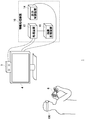
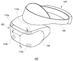
- FIG. 7 shows an example of the external shape of the HMD 100.
- the HMD 100 includes an output mechanism unit 102 and a mounting mechanism unit 104.
- the wearing mechanism unit 104 includes a wearing band 106 that goes around the head when the user wears and fixes the HMD 100 to the head.
- the wearing band 106 has a material or a structure whose length can be adjusted according to the user's head circumference.
- the output mechanism unit 102 includes a housing 108 shaped to cover the left and right eyes when the user wears the HMD 100, and includes a display panel that faces the eyes when worn.
- the display panel may be a liquid crystal panel or an organic EL panel.
- the housing 108 is further provided with a pair of left and right optical lenses that are positioned between the display panel and the user's eyes and expand the viewing angle of the user.
- the HMD 100 may further include a speaker or an earphone at a position corresponding to the user's ear.
- the tracking LED constitutes the light emitting marker 110, but it may be any other type of marker, and in any case, the information is captured by the imaging device 7 and the information processing device 10 can analyze the image of the marker position. I just need it.
- the number and arrangement of the light emitting markers 110 are not particularly limited, but need to be the number and arrangement for detecting the posture of the HMD 100.
- the light emitting markers 110 are provided at the four corners on the front surface of the housing 108. Further, the light emitting marker 110 may be provided on the side or the rear of the wearing band 106 so that the user can take an image when the user turns his back to the imaging device 7.
- the HMD 100 may be connected to the information processing apparatus 10 with a cable or may be connected with a known wireless communication protocol.
- the HMD 100 transmits the sensor information detected by the posture sensor to the information processing apparatus 10, receives parallax image data generated by the information processing apparatus 10, and displays the parallax image data on the left-eye display panel and the right-eye display panel.
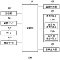
- FIG. 8 shows functional blocks of the HMD 100.
- the control unit 120 is a main processor that processes and outputs various data such as image data, audio data, sensor information, and commands.
- the storage unit 122 temporarily stores data, commands, and the like that are processed by the control unit 120.
- the posture sensor 124 detects posture information of the HMD 100.
- the posture sensor 124 includes at least a triaxial acceleration sensor and a triaxial gyro sensor.
- XYZ three-dimensional coordinates are set in the HMD 100 as shown in FIG.
- the pitch axis is set to the X axis
- the yaw axis is set to the Y axis
- the roll axis is set to the Z axis.
- the first acceleration sensor detects acceleration in the pitch axis direction
- the first gyro sensor detects angular velocity around the pitch axis.
- the second acceleration sensor detects acceleration in the yaw axis direction
- the second gyro sensor detects angular velocity around the yaw axis.
- the third acceleration sensor detects acceleration in the roll axis direction
- the third gyro sensor detects angular velocity around the roll axis.
- the communication control unit 128 transmits data output from the control unit 120 to the external information processing apparatus 10 by wired or wireless communication via a network adapter or an antenna. In addition, the communication control unit 128 receives data from the information processing apparatus 10 through wired or wireless communication via a network adapter or an antenna, and outputs the data to the control unit 120.
- control unit 120 When the control unit 120 receives image data or audio data from the information processing apparatus 10, the control unit 120 supplies the image data and audio data to the display panel 130 for display, and supplies them to the audio output unit 132 for audio output.
- the display panel 130 includes a left-eye display panel 130a and a right-eye display panel 130b, and a pair of parallax images having a predetermined amount of parallax are displayed on each display panel. Further, the control unit 120 causes the communication control unit 128 to transmit the sensor information from the attitude sensor 124 and the audio data from the microphone 126 to the information processing apparatus 10.
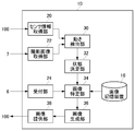
- FIG. 9 shows functional blocks of the information processing apparatus 10.
- the information processing apparatus 10 includes a sensor information acquisition unit 20, a captured image acquisition unit 22, a reception unit 24, and an image provision unit 38 as an input / output interface with the outside.
- the sensor information acquisition unit 20 acquires sensor information from the attitude sensor 124 of the HMD 100 at a predetermined cycle.
- the captured image acquisition unit 22 acquires an image obtained by capturing the HMD 100 from the imaging device 7 at a predetermined cycle. For example, the imaging device 7 captures a front space every (1/60) second, and the captured image acquisition unit 22 acquires a captured image every (1/60) second.
- the receiving unit 24 acquires information input by the user from the input device 6.
- the information processing apparatus 10 further includes a motion detection unit 30, a state determination unit 32, an image specification unit 34, and an image generation unit 36.
- the motion detection unit 30 detects the position coordinates and orientation of the HMD 100 based on the motion of the HMD 100 mounted on the user's head.
- the state determination unit 32 determines the viewpoint position of the user according to the position coordinates of the HMD 100 detected by the motion detection unit 30, and according to the posture of the HMD 100, the line of sight of the user and the line connecting the user's eyes A binocular tilt angle that is an angle with the horizontal plane is determined.
- the image specifying unit 34 specifies two images used for generating the left-eye and right-eye parallax images from the plurality of viewpoint images stored in the image storage device 16. At this time, the image specifying unit 34 specifies two images used for generating a parallax image based on at least the user's line-of-sight direction and the binocular tilt angle determined by the state determining unit 32. In the embodiment, for the convenience of explanation, it is assumed that the user's line-of-sight direction is parallel to the horizontal plane.
- the image generation unit 36 generates left-eye and right-eye parallax images from the two images specified by the image specification unit 34.
- the image providing unit 38 provides the parallax image generated by the image generating unit 36 to the HMD 100.
- each element described as a functional block for performing various processes can be configured by a circuit block, a memory, and other LSIs in terms of hardware, and loaded into the memory in terms of software. Realized by programs. Therefore, it is understood by those skilled in the art that these functional blocks can be realized in various forms by hardware only, software only, or a combination thereof, and is not limited to any one.
- the image storage device 16 stores a plurality of viewpoint images acquired from a plurality of viewpoint positions in association with coordinate values representing viewpoint positions on two-dimensional coordinates.
- a virtual two-dimensional coordinate plane is set for each multi-viewpoint image captured simultaneously by the multi-viewpoint camera 18.
- the photographing operation of the subject using the multi-view camera 18 is performed every time the angle on the horizontal plane is moved by a predetermined angle ⁇ around the predetermined position while the line-of-sight direction of the multi-view camera 18 is maintained in the horizontal direction. Is done.
- the predetermined angle ⁇ is set to 0.1 degrees
- 3600 types of multi-viewpoint images are generated by performing a shooting operation by rotating the multi-viewpoint camera 18 by 0.1 degrees and taking a total of 3600 times. .
- the multiview camera 18 When the predetermined angle ⁇ is 10 degrees, the multiview camera 18 is rotated 10 degrees at a time, and 36 kinds of multiview images are generated by performing a total of 36 times of photographing. With such a photographing operation, the image storage device 16 stores a 360-degree panoramic image. In addition, a suitable parallax image can be provided to a user, so that the rotation angle (beta) in imaging
- the sensor information acquisition unit 20 acquires the sensor information of the attitude sensor 124 and supplies it to the motion detection unit 30.
- the captured image acquisition unit 22 acquires a captured image and supplies it to the motion detection unit 30.
- the motion detection unit 30 detects the motion of the HMD 100 mounted on the user's head and identifies the position coordinates and orientation of the HMD 100. This process is performed to synchronize the visual field displayed on the display panel 130 of the HMD 100 with the movement of the user's head. This head tracking process may use a known method.
- the motion detection unit 30 detects the position coordinates and orientation of the HMD 100 from the sensor information of the orientation sensor 124.
- the motion detection unit 30 specifies the position coordinates of the HMD 100 from the sensor information of the 3-axis acceleration sensor, and specifies the attitude of the HMD 100 from the sensor information of the 3-axis gyro sensor.
- the position coordinates are derived from position coordinates in the pitch axis direction (X coordinate), position coordinates in the yaw axis direction (Y coordinate), and position coordinates in the roll axis direction (Z coordinate) when the reference position is the origin.
- the attitude of the HMD 100 is derived from an angle around the pitch axis (pitch angle), an angle around the yaw axis (yaw angle), and an angle around the roll axis (roll angle) with respect to the reference attitude.
- the motion detection unit 30 further increases the detection accuracy of the position coordinates and orientation by further using the imaging result of the tracking light emitting marker 110.
- the motion detection unit 30 detects the position coordinates and orientation of the HMD 100 at a predetermined cycle. For example, if the image supplied to the HMD 100 is 60 fps, it is preferable that the detection process of the motion detection unit 30 is also executed at a period of (1/60) seconds.
- the information processing apparatus 10 generates a parallax image based on the position information and posture of the HMD 100 will be described.
- the state determination unit 32 determines the user's viewpoint position, gaze direction, and binocular tilt angle according to the position information and posture of the HMD 100 detected by the motion detection unit 30.
- the viewpoint position of the user is defined as the position of the center point of both eyes.
- the user's line-of-sight direction is defined as a direction in which the front of the face faces from the user's viewpoint position.
- the binocular tilt angle is defined as an angle between a line connecting both eyes and a horizontal plane.
- the state determination unit 32 determines the viewpoint position of the user based on the position information of the HMD 100, and further determines the viewpoint position of the virtual camera 8 according to the determined viewpoint position of the user.
- the viewpoint position of the virtual camera 8 may be set to a fixed position in the virtual cylindrical body regardless of the viewpoint position of the user. In this case, the viewpoint position of the virtual camera 8 is set to a predetermined position on the central axis in the virtual cylinder (see FIG. 6).
- the state determination unit 32 determines the user's line-of-sight direction based on the attitude of the HMD 100.
- the state determination unit 32 may determine the determined user's line-of-sight direction as it is as the line-of-sight direction (optical axis direction) of the virtual camera 8 or may perform some correction processing to determine the line-of-sight direction of the virtual camera 8. Also good. For example, when noise is added to the sensor information and stable sensor information is not provided to the motion detection unit 30, the motion detection unit 30 performs a motion that vibrates even though the user's head is not moving. There is a possibility of detection. In such a case, the state determination unit 32 may smoothly correct the motion detected by the motion detection unit 30 to determine the user's line-of-sight direction and the virtual camera 8's line-of-sight direction.
- the user's line-of-sight direction corresponds to the line-of-sight direction (optical axis direction) of the virtual camera 8 arranged in the virtual cylinder (see FIG. 6).
- the virtual camera 8 has a baseline length with a default value of 20 mm.
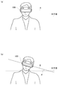
- FIG. 10A and FIG. 10B are diagrams for explaining the binocular tilt angle. 10A and 10B, it is assumed that the user's line-of-sight direction is parallel to the horizontal plane. A line connecting both eyes of the user may be defined in the housing width direction of the HMD 100.
- FIG. 10A shows the posture of the HMD 100 in which the binocular tilt angle is zero. In this case, the user does not tilt the neck in the lateral direction, and therefore the line A connecting both eyes is parallel to the horizontal plane.
- FIG. 10B shows the posture of the HMD 100 in which the binocular tilt angle is ⁇ . By tilting the neck in the lateral direction, the line connecting both eyes has an angle with respect to the horizontal plane. In this example, the user tilts his / her neck to the left as viewed from the user, and the line B connecting both eyes has an angle ⁇ with respect to the horizontal plane. In this example, the binocular tilt angle ⁇ corresponds to the roll angle.
- the image specifying unit 34 uses the left eye and the right eye from a plurality of viewpoint images stored in the image storage device 16 based on at least the user's line-of-sight direction and binocular tilt angle determined by the state determination unit 32. A method for specifying two images used for generating a parallax image will be described.
- the image storage device 16 stores a plurality of types of multi-viewpoint images in association with the line-of-sight direction at the time of acquisition.
- the multi-view camera 18 captures multi-view images at intervals of 0.1 degrees, 3600 types of multi-view images are stored in the image storage device 16.
- Each multi-viewpoint image includes a plurality of viewpoint images, and each viewpoint image is stored in the image storage device 16 in association with a viewpoint position of a two-dimensional coordinate set for each multi-viewpoint image.
- the image specifying unit 34 specifies a multi-viewpoint image acquired in a line-of-sight direction that matches the user's line-of-sight direction from a plurality of types of multi-viewpoint images acquired in different line-of-sight directions. For example, when the resolution in the user line-of-sight direction in the state determination unit 32 is 0.1 degree and the image storage device 16 holds multi-viewpoint images in the line-of-sight direction at intervals of 0.1 degree, it matches the user line-of-sight direction. A multi-viewpoint image is always held.
- the multi-viewpoint image acquired in the line-of-sight direction that matches the user's line-of-sight direction is the multi-viewpoint image illustrated in FIG. 5 will be described.
- the image specifying unit 34 coordinates the line-of-sight direction starting from the user's viewpoint position through the two-dimensional coordinate plane of the multi-viewpoint image Determine.
- the user's line-of-sight direction is orthogonal to the two-dimensional coordinate plane.
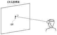
- FIG. 11 shows the intersection between the user's line-of-sight direction and the two-dimensional coordinate plane.
- the coordinate value of the intersection represents the viewpoint position of the virtual camera 8 facing the two-dimensional coordinate plane, that is, the user's viewpoint position.
- an intersection coordinate value between the two-dimensional coordinate plane and the user's line-of-sight direction is referred to as a user's "line-of-sight position EP".
- FIG. 12 shows an example in which the user's line-of-sight direction position EP in the two-dimensional coordinate plane is derived.
- the line-of-sight direction position EP is derived as a coordinate value (0, 3) on the two-dimensional coordinate plane.
- the image specifying unit 34 specifies two images used for generating the left-eye and right-eye parallax images based on the binocular tilt angle determined by the state determination unit 32.
- the coordinate value of the viewpoint image used for generating the left-eye image 5a is referred to as “left-eye image position LP”
- the coordinate value of the viewpoint image used for generating the right-eye image 5b is referred to as “right-eye image position RP”.
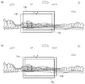
- FIG. 13A shows an example of the identified left-eye image position LP and right-eye image position RP.
- FIG. 13A shows the left-eye image position LP and the right-eye image position RP that are specified when the user does not tilt the neck horizontally as shown in FIG.
- the image specifying unit 34 specifies two images that are located at an equal distance in the direction along the binocular tilt angle from the line-of-sight direction position EP and whose distance between the viewpoint positions of the two images is a set distance. That is, on the two-dimensional coordinate plane, the left-eye image position LP, the line-of-sight position EP, and the right-eye image position RP are aligned on a straight line, and the distance from the line-of-sight direction position EP to the left-eye image position LP and the line-of-sight position EP The image specifying unit 34 determines the left-eye image position LP and the right-eye image position RP with reference to the line-of-sight direction position EP so that the distance to the right-eye image position RP is equal.
- the set distance between the image position LP for the left eye and the image position RP for the right eye corresponds to the base line length of the virtual camera 8, that is, the distance between the left camera and the right camera.
- the base line length of the virtual camera 8 is set to 20 mm by default. Therefore, the image specifying unit 34 sets the left-eye image position LP and the right-eye image so that the parallax between the left-eye image and the right-eye image is 20 mm.
- a position RP is determined.
- the binocular tilt angle which is the angle between the line connecting the user's eyes and the horizontal plane, is zero, so the left-eye image position LP is coordinates ( ⁇ 5, 3), and the right-eye image position RP is coordinates (5 , 3).
- FIG. 13B shows another example of the identified left-eye image position LP and right-eye image position RP.
- FIG. 13B shows a left-eye image position LP and a right-eye image position RP that are specified when the user tilts his / her neck in the horizontal direction as shown in FIG. 10B.
- an example is shown in which the user tilts his / her neck to the left as shown in FIG. 10 (b) from the state shown in FIG. 10 (a). Therefore, the line-of-sight direction position EP moves from the coordinates (0, 3) to the coordinates ( ⁇ 1, 2) counterclockwise.
- the image specifying unit 34 specifies two images that are located at an equal distance in the direction along the binocular tilt angle from the line-of-sight direction position EP and whose distance between the viewpoint positions of the two images is a set distance.
- the binocular tilt angle is ⁇
- the left-eye image position LP is specified as coordinates ( ⁇ 5, ⁇ 1)
- the right-eye image position RP is specified as coordinates (3, 5).
- the image position LP for the left eye and the image position RP for the right eye are derived using the following parameters.
- the parallax in the x direction between the image position LP for the left eye and the image position RP for the right eye is ipd ⁇ cos ( ⁇ ), and the parallax in the y direction is ipd ⁇ sin ( ⁇ ).
- the parallax setting distance ipd is preferably freely changeable by the user.
- the accepting unit 24 can accept designation of a set distance from the user.
- the image specifying unit 34 changes the set distance based on the designation accepted by the accepting unit 24.
- the change of the set distance corresponds to the change of the parameter value of ipd in the derivation formula.
- the image specifying unit 34 specifies the multi-viewpoint image that is the material of the parallax image based on the user's line-of-sight direction from the multiple types of multi-viewpoint images stored in the image storage device 16. Two images used for generating a parallax image are specified based on the binocular tilt angle from a plurality of viewpoint images included in the specified multi-viewpoint image. For example, in the example shown in FIG. 13A, the image specifying unit 34 uses the viewpoint image associated with the coordinates ( ⁇ 5, 3) to generate the left-eye image 5a, and the right-eye image 5b. It is determined that the viewpoint image associated with the coordinates (5, 3) is used for generation. In the example shown in FIG.
- the image specifying unit 34 uses the viewpoint image associated with the coordinates ( ⁇ 5, ⁇ 1) to generate the left-eye image 5a, and the right-eye image 5b. It is determined to use the viewpoint image associated with the coordinates (3, 5) for the generation of.
- the image generation unit 36 generates parallax images for the left eye and the right eye from the two viewpoint images specified by the image specification unit 34. At this time, the image generation unit 36 generates a parallax image in which the angles of the two images are adjusted based on the binocular tilt angle ⁇ .
- the binocular tilt angle is not zero, that is, when the user's neck is tilted laterally, the top and bottom of the left-eye display panel 130a and the right-eye display panel 130b are tilted with respect to the vertical direction. Therefore, when the top and bottom of the left-eye display panel 130a and the right-eye display panel 130b are aligned with the top and bottom of the display image, an image tilted by the binocular tilt angle ⁇ is displayed to the user's eyes.
- the image generation unit 36 rotates the two viewpoint images specified by the image specifying unit 34 by ⁇ , respectively, and the angle of view of the left-eye display panel 130a and the right-eye display panel 130b from the ⁇ -rotated viewpoint images.
- Min. Image is cut out to generate a left-eye image 5a and a right-eye image 5b. That is, the image generation unit 36 adjusts the angles of the two viewpoint images so that the top and bottom of the images displayed on the left-eye display panel 130a and the right-eye display panel 130b are aligned with the actual top and bottom.
- the viewpoint image stored in the image storage device 16 is configured to be larger than the angle of view of the image displayed on the left-eye display panel 130a and the right-eye display panel 130b. Therefore, the left-eye image 5a and the right-eye image 5b corresponding to the angle of view of the left-eye display panel 130a and the right-eye display panel 130b can be cut out from the viewpoint image that has been rotated by - ⁇ . Since the image light from the display panel 130 passes through the optical lens and reaches the user's eyes, the image generation unit 36 preferably generates a parallax image in which distortion due to the optical lens passage is corrected.
- the image providing unit 38 provides the parallax image to the HMD 100.
- the control unit 120 displays the left-eye image on the left-eye display panel 130a and the right-eye image on the right-eye display panel 130b, whereby the user displays on the left-eye display panel 130a and the right-eye display panel 130b. Can be seen.
- the information processing apparatus 10 displays an appropriate parallax image even when the horizontal height of both eyes of the user is different. It can be provided to HMD100.
- the image storage device 16 stores, as a plurality of viewpoint images, a plurality of real viewpoint images acquired by the camera 19 and a plurality of interpolation images generated by interpolation processing from at least two real viewpoint images. Yes. Therefore, the image specifying unit 34 selects two images used for generating a parallax image from a plurality of real viewpoint images and a plurality of interpolation images (virtual viewpoint images).
- the image storage device 16 stores only a plurality of actual viewpoint images acquired by the camera 19 as a plurality of viewpoint images.
- the image specifying unit 34 determines, from the plurality of real viewpoint images stored in the image storage device 16, two images used for generating parallax images for the left eye and the right eye for the user's line of sight determined by the image specifying unit 34. It may be generated in real time by interpolation processing based on the direction and the binocular tilt angle. This has the advantage that a large amount of interpolated images need not be generated in advance.
- the image storage device 16 may store a plurality of real viewpoint images and some of the interpolated images. Some of the interpolated images are images for quickly generating a virtual viewpoint image having an arbitrary coordinate value, and may be, for example, an interpolated image positioned between two real viewpoint images. Thus, when performing interpolation processing in real time, a device for increasing the interpolation processing speed may be taken.
- the above is processing when the image specifying unit 34 specifies a multi-viewpoint image captured in a line-of-sight direction that matches the user's line-of-sight direction from a plurality of types of multi-viewpoint images.
- the image specifying unit 34 matches the line-of-sight direction of the user It is possible to specify a multi-viewpoint image captured in the viewing direction.
- FIG. 14 is a diagram for explaining the line-of-sight direction and the angle of view of a multi-viewpoint image.
- FIG. 14 shows the line-of-sight direction and the angle of view of the real viewpoint image and the virtual viewpoint image (interpolated image) from the upper surface side of the multi-viewpoint camera 18.
- Each viewpoint image is an image obtained by photographing a subject at a predetermined angle of view around each line-of-sight direction.
- 10 line-of-sight directions are represented for convenience, but as described in the embodiment, 21 line-of-sight directions are actually arranged in the horizontal direction.
- the two-dimensional coordinate plane 15 is a virtual two-dimensional plane for expressing the viewpoint position in each viewpoint image, and the distance between the multi-viewpoint camera 18 and the two-dimensional coordinate plane 15 corresponds to the radius of the virtual cylindrical body.
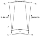
- FIG. 15 is a diagram showing the relationship of the two-dimensional coordinate plane 15 of the multi-viewpoint image acquired by rotating the multi-viewpoint camera 18 by a predetermined angle ⁇ .
- the multi-view camera 18a acquires a subject image in the first viewing direction
- the multi-view camera 18b acquires a subject image in the second viewing direction.
- the first viewing direction of the multi-view camera 18a and the second viewing direction of the multi-view camera 18b are shifted by an angle ⁇ .
- the image specifying unit 34 selects two multi-view images acquired in the line-of-sight direction that matches the user's line-of-sight direction, and forms two parallax images from the selected multi-view images.
- the viewpoint image was specified. For example, also in the multi-viewpoint image shown in FIG. 15, if the user's line-of-sight direction matches the first line-of-sight direction, the image specifying unit 34 selects the multi-viewpoint image acquired by the multi-viewpoint camera 18a, while If the line-of-sight direction matches the second line-of-sight direction, the image specifying unit 34 selects the multi-viewpoint image acquired by the multi-viewpoint camera 18b.
- the image specifying unit 34 selects a multi-viewpoint image when the user's line-of-sight vector exists between the first line-of-sight vector and the second line-of-sight vector. More precisely, when the vector of the user's line-of-sight direction is projected onto the plane defined by the vector of the first line-of-sight direction and the vector of the second line-of-sight direction, the direction of the projected vector is the first line-of-sight direction. A description will be given of how the image specifying unit 34 selects a multi-viewpoint image when it is between the second line-of-sight directions.
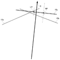
- FIG. 16 shows an example of the user's line-of-sight direction S.
- the user's line-of-sight direction S uses the rotation center of the multi-view camera 18 as the viewpoint position (starting point), but the viewpoint position is not limited to this position.
- the image specifying unit 34 has a plurality of viewpoint images acquired in the first line-of-sight direction and / or a plurality of points acquired in the second line-of-sight direction. From the viewpoint images, at least two images used for generating the left-eye and right-eye parallax images are specified based on the user's line-of-sight direction and binocular tilt angle determined by the state determination unit 32.
- the image specifying unit 34 compares the angle A1 formed by the first line-of-sight direction and the user line-of-sight direction S with the angle A2 formed by the second line-of-sight direction and the user line-of-sight direction S, and is closer to the user line-of-sight direction S. That is, a multi-viewpoint image with a smaller angle may be selected. For example, if angle A1> angle A2, the image specifying unit 34 specifies two images used for generating a parallax image using a second image group including a plurality of viewpoint images acquired in the second line-of-sight direction. Decide that.
- the image specifying unit 34 uses the first image group including a plurality of viewpoint images acquired in the first line-of-sight direction to specify two images used for generating a parallax image. Decide what to do. As described above, the image specifying unit 34 selects the first image group including the plurality of viewpoint images acquired in the first viewing direction or the plurality of viewpoint images acquired in the second viewing direction based on the user's viewing direction S. It may be determined which of the included second image groups is used to specify the two images.
- the two-dimensional coordinate plane 15 is not orthogonal to the user's line-of-sight direction S, regardless of whether the first image group or the second image group is used. Therefore, the image generation unit 36 needs to projectively transform the image group to be used according to the user's line-of-sight direction S.
- the image specifying unit 34 includes both a first image group including a plurality of viewpoint images acquired in the first viewing direction and a second image group including a plurality of viewpoint images acquired in the second viewing direction. May be used to identify at least two images used to generate a parallax image.
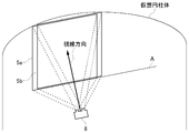
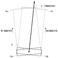
- FIG. 17 is a diagram for describing an example in which a parallax image is generated using both the first image group and the second image group.
- FIG. 17 shows the positional relationship between the two-dimensional coordinate plane 15a, the two-dimensional coordinate plane 15b, and the user's line-of-sight direction S.
- the two-dimensional coordinate plane 15s is a virtual plane orthogonal to the user's line-of-sight direction S.
- the image specifying unit 34 specifies the image position LP for the left eye and the image position RP for the right eye on the two-dimensional coordinate surface 15s.
- a line orthogonal to the two-dimensional coordinate plane 15s is drawn from the image position LP for the left eye and the image position RP for the right eye, if the orthogonal line intersects the two-dimensional coordinate plane 15a and the two-dimensional coordinate plane 15b, it corresponds to the intersection.
- the attached viewpoint image can be used to generate a parallax image.
- the orthogonal line passing through the left-eye image position LP intersects the two-dimensional coordinate plane 15a and the two-dimensional coordinate plane 15b, while the orthogonal line passing through the right-eye image position RP is the two-dimensional coordinate plane.
- Crosses 15b but does not cross the two-dimensional coordinate plane 15a. This means that the viewpoint image corresponding to the image position RP for the right eye on the two-dimensional coordinate surface 15s does not exist on the two-dimensional coordinate surface 15a.
- the relationship of the two-dimensional coordinate plane 15 is expressed one-dimensionally, but in reality, the intersection is determined two-dimensionally.
- the image generation unit 36 has a function of synthesizing the viewpoint image acquired in the first line-of-sight direction and the viewpoint image acquired in the second line-of-sight direction. This synthesis is performed after projective transformation of each viewpoint image according to the user's line-of-sight direction S. In the example illustrated in FIG. 17, the image generation unit 36 synthesizes the viewpoint image acquired in the first line-of-sight direction and the viewpoint image acquired in the second line-of-sight direction when generating the left-eye image 5 a. By generating the left-eye image 5a from the two viewpoint images, a more accurate image can be reproduced. Note that when the right-eye image 5b is generated, there is no viewpoint image in the first line-of-sight direction, so the image generation unit 36 generates the right-eye image 5b from the viewpoint image in the second line-of-sight direction.
- the present invention is not limited to this.
- the viewpoint image is acquired in the line-of-sight direction parallel to the horizontal plane, while the user's line-of-sight direction is parallel to the horizontal plane.
- the image generation unit 36 performs projective transformation of the viewpoint image so that the user's line-of-sight direction matches the line-of-sight direction of image acquisition, and a suitable parallax image can be generated.
- SYMBOLS 1 Information processing system, 10 ... Information processing apparatus, 12 ... Processing apparatus, 14 ... Output control apparatus, 16 ... Image storage apparatus, 20 ... Sensor information acquisition part, 22. ..A captured image acquisition unit, 24... Reception unit, 30... Motion detection unit, 32... State determination unit, 34. Image provider.
- the present invention can be used in the technical field of generating an image to be displayed on a head mounted display.
Abstract
A motion detection unit 30 detects an attitude of an HMD mounted on the head of a user. A state determination unit 32 determines a user's gaze direction, and a binocular inclination angle that is an angle between a line connecting both eyes and a horizontal plane, in accordance with the detected posture of the HMD. An image specification unit 34 specifies two images that are used to generate disparity images for a left eye and a right eye from a plurality of viewpoint images stored in an image storage device 16, on the basis of the user's gaze direction and the binocular inclination angle. An image generation unit 36 generates the disparity images for the left eye and the right eye from the specified two images. An image provision unit 38 provides the generated disparity images to the HMD.
Description
本発明は、ヘッドマウントディスプレイに表示する視差画像を生成する技術および/または視差画像をヘッドマウントディスプレイに表示する技術に関する。
The present invention relates to a technique for generating a parallax image to be displayed on a head-mounted display and / or a technique for displaying a parallax image on a head-mounted display.
ヘッドマウントディスプレイ(HMD)はユーザの頭部に装着されて仮想現実(VR)の世界をユーザに提供する。HMDにヘッドトラッキング機能をもたせ、ユーザの頭部の動きに連動して表示画面を更新することで、映像世界への没入感を高められる。近年、パノラマ写真を撮影する技術が普及しており、撮影されたパノラマ写真画像をHMDに表示することで、現実の場所にいるかのような感覚をユーザに与えられる。
The head mounted display (HMD) is mounted on the user's head to provide the user with a virtual reality (VR) world. By providing the HMD with a head tracking function and updating the display screen in conjunction with the movement of the user's head, it is possible to enhance the sense of immersion in the video world. In recent years, a technique for taking a panoramic photograph has become widespread, and by displaying the taken panoramic photograph image on the HMD, a user can feel as if he / she is in a real place.
HMDにはユーザの左目用および右目用の表示パネルが設けられ、各表示パネルからそれぞれ左目用と右目用の画像(視差画像)が表示されることで、ステレオ立体視が実現される。ゲームアプリケーションでは、ゲーム空間内に左目用の仮想カメラと右目用の仮想カメラとを配置することで左目用と右目用のゲーム画像を生成して、HMDのそれぞれの表示パネルから出力できる。
The HMD is provided with a display panel for the user's left eye and right eye, and a stereo stereoscopic view is realized by displaying a left eye image and a right eye image (parallax image) from each display panel. In the game application, the left-eye virtual camera and the right-eye virtual camera are arranged in the game space to generate the left-eye and right-eye game images and output them from the respective display panels of the HMD.
実写された被写体画像をHMDに表示するVRアプリケーションでは、ステレオ立体視表示のために、素材となるコンテンツ画像がステレオカメラを用いて撮影されていることが一般的である。ステレオカメラを用いた被写体の撮影作業は、左カメラと右カメラとを水平に維持した状態で、定点から上下方向および左右方向に所定量ずつ回転移動させて都度撮影することで行われる。そのためHMDを装着したユーザが首を上下または左右に振る動きに対しては、ユーザの両眼の水平方向の高さが揃っているために、ステレオ画像の素材をもとに視差量を一定とする視差画像を生成できる。
In a VR application that displays a photographed subject image on the HMD, a content image as a material is generally captured using a stereo camera for stereo stereoscopic display. The subject is photographed using the stereo camera by photographing each time by rotating the left camera and the right camera horizontally by a predetermined amount from the fixed point in the up and down direction and the left and right direction. Therefore, when the user wearing the HMD swings his / her neck up / down or left / right, the horizontal height of both eyes of the user is uniform, so the parallax amount is constant based on the material of the stereo image. A parallax image can be generated.
しかしながらユーザが正面を向いたまま首を横に傾ける(首を肩に近づける)ことで、両眼を結ぶ線と水平面との角度が斜めとなり、両眼の水平方向の高さが揃わなくなるケースでは、ステレオカメラを同じ角度で傾けて撮影した素材がなければ、視差量を一定とする視差画像を生成することが困難となる。水平面に対して全ての角度にステレオカメラを傾けて被写体を撮影することは現実的にほぼ不可能であるため、HMD使用時にユーザが首を横に傾けると、適切な視差画像を提供できないという問題が発生する。そこでHMDを装着したユーザが首を横に傾けた場合であっても、視差量を一定とする視差画像を生成する技術の開発が望まれている。
However, in the case where the user tilts the neck sideways while facing the front (the neck is brought closer to the shoulder), the angle between the line connecting both eyes and the horizontal plane becomes oblique, and the horizontal height of both eyes cannot be aligned. If there is no material photographed by tilting the stereo camera at the same angle, it is difficult to generate a parallax image with a constant parallax amount. In reality, it is almost impossible to shoot a subject by tilting the stereo camera at all angles with respect to the horizontal plane. Therefore, if the user tilts his / her neck sideways when using the HMD, an appropriate parallax image cannot be provided. Will occur. Therefore, it is desired to develop a technique for generating a parallax image with a constant parallax amount even when the user wearing the HMD tilts his / her neck sideways.
本発明はこうした課題に鑑みてなされたものであり、その目的は、HMDで表示するための視差画像を適切に生成する技術および/または視差画像を表示する技術を提供することにある。
The present invention has been made in view of these problems, and an object of the present invention is to provide a technique for appropriately generating a parallax image to be displayed by an HMD and / or a technique for displaying a parallax image.
上記課題を解決するために、本発明のある態様の情報処理装置は、ユーザの頭部に装着されたヘッドマウントディスプレイの姿勢を検出する検出部と、検出部により検出されたヘッドマウントディスプレイの姿勢に応じて、ユーザの視線方向、および両眼を結ぶ線と水平面との角度である両眼傾き角度を定める状態決定部と、複数の視点画像から左目用と右目用の視差画像の生成に用いる2つの画像を、状態決定部で定めたユーザの視線方向および両眼傾き角度にもとづいて特定する画像特定部と、画像特定部が特定した2つの画像から左目用と右目用の視差画像を生成する画像生成部と、画像生成部が生成した視差画像をヘッドマウントディスプレイに提供する画像提供部と、を備える。
In order to solve the above-described problems, an information processing apparatus according to an aspect of the present invention includes a detection unit that detects a posture of a head-mounted display attached to a user's head, and a posture of the head-mounted display that is detected by the detection unit. And determining the binocular tilt angle, which is the angle between the line of sight of the user and the line connecting both eyes and the horizontal plane, and generating parallax images for the left and right eyes from a plurality of viewpoint images. An image specifying unit for specifying two images based on the user's line-of-sight direction and binocular tilt angle determined by the state determining unit, and generating a parallax image for the left eye and right eye from the two images specified by the image specifying unit And an image providing unit that provides a parallax image generated by the image generating unit to a head mounted display.
本発明の別の態様の情報処理装置は、ユーザの頭部に装着されたヘッドマウントディスプレイの姿勢を検出する検出部と、検出部により検出されたヘッドマウントディスプレイの姿勢に応じて、ユーザの視線方向、および両眼を結ぶ線と水平面との角度である両眼傾き角度を定める状態決定部と、第1視線方向において取得された複数の視点画像および/または第2視線方向において取得された複数の視点画像から、左目用と右目用の視差画像の生成に用いる少なくとも2つの画像を、状態決定部で定めたユーザの視線方向および両眼傾き角度にもとづいて特定する画像特定部と、画像特定部が特定した少なくとも2つの画像から左目用と右目用の視差画像を生成する画像生成部と、画像生成部が生成した視差画像をヘッドマウントディスプレイに提供する画像提供部と、を備える。
An information processing apparatus according to another aspect of the present invention includes a detection unit that detects a posture of a head mounted display mounted on a user's head, and a user's line of sight according to the posture of the head mounted display detected by the detection unit. A state determining unit that determines a binocular tilt angle that is an angle between a direction and a line connecting both eyes and a horizontal plane, and a plurality of viewpoint images acquired in the first line-of-sight direction and / or a plurality of acquired in the second line-of-sight direction An image specifying unit for specifying at least two images used for generating a left-eye parallax image and a right-eye parallax image based on a user's line-of-sight direction and binocular tilt angle determined by the state determination unit, and an image specification An image generation unit that generates parallax images for the left eye and right eye from at least two images specified by the unit, and the parallax image generated by the image generation unit Comprising an image providing unit for providing a ray, the.
本発明のさらに別の態様は、左目用表示パネルと右目用表示パネルとを備えたヘッドマウントディスプレイに関する。当該ヘッドマウントディスプレイは、装着したユーザの視線方向、およびユーザの両眼を結ぶ線と水平面との角度である両眼傾き角度にもとづいて特定された2つの視点画像から生成された左目用と右目用の画像データを受け取り、左目用表示パネルと右目用表示パネルに表示させる制御部をさらに備える。
Still another aspect of the present invention relates to a head-mounted display including a left-eye display panel and a right-eye display panel. The head-mounted display is for the left eye and the right eye that are generated from two viewpoint images that are specified based on the viewing direction of the user who wears them and the binocular tilt angle that is the angle between the line connecting the eyes of the user and the horizontal plane. And a control unit for receiving the image data for display on the left-eye display panel and the right-eye display panel.
なお、以上の構成要素の任意の組合せ、本発明の表現を方法、装置、システム、コンピュータプログラム、コンピュータプログラムを読み取り可能に記録した記録媒体、データ構造などの間で変換したものもまた、本発明の態様として有効である。
Note that any combination of the above components, the expression of the present invention converted between a method, an apparatus, a system, a computer program, a recording medium on which the computer program is recorded so as to be readable, a data structure, and the like are also included in the present invention. It is effective as an embodiment of
図1は、実施例における情報処理システム1の構成例を示す。情報処理システム1は情報処理装置10と、ユーザが頭部に装着するヘッドマウントディスプレイ装置(HMD)100と、ユーザが手指で操作する入力装置6と、HMD100を装着したユーザを撮影する撮像装置7と、画像を表示する出力装置4とを備える。
FIG. 1 shows a configuration example of an information processing system 1 in the embodiment. The information processing system 1 includes an information processing device 10, a head mounted display device (HMD) 100 that the user wears on the head, an input device 6 that the user operates with fingers, and an imaging device 7 that photographs the user wearing the HMD 100. And an output device 4 for displaying an image.
実施例において情報処理装置10は、処理装置12、出力制御装置14および画像記憶装置16を備える。処理装置12は、ユーザにより操作された入力装置6の操作情報を受けて、様々なアプリケーションを実行する端末装置である。処理装置12と入力装置6とはケーブルで接続されてよく、また既知の無線通信プロトコルで接続されてもよい。出力制御装置14は、処理装置12で生成された画像データをHMD100に出力する処理ユニットである。出力制御装置14とHMD100とはケーブルで接続されてよく、また既知の無線通信プロトコルで接続されてもよい。
In the embodiment, the information processing apparatus 10 includes a processing device 12, an output control device 14, and an image storage device 16. The processing device 12 is a terminal device that receives operation information of the input device 6 operated by a user and executes various applications. The processing device 12 and the input device 6 may be connected by a cable or may be connected by a known wireless communication protocol. The output control device 14 is a processing unit that outputs the image data generated by the processing device 12 to the HMD 100. The output control device 14 and the HMD 100 may be connected by a cable or may be connected by a known wireless communication protocol.
撮像装置7はステレオカメラであって、HMD100を装着したユーザを所定の周期で撮影し、撮影画像を処理装置12に供給する。後述するがHMD100には、ユーザ頭部をトラッキングするためのマーカ(トラッキング用LED)が設けられ、処理装置12は、撮影画像に含まれるマーカの位置にもとづいてHMD100の動きを検出する。なおHMD100には姿勢センサ(加速度センサおよびジャイロセンサ)が搭載され、処理装置12は、姿勢センサで検出されたセンサ情報をHMD100から取得することで、マーカの撮影画像の利用とあわせて、高精度のトラッキング処理を実施する。なおトラッキング処理については従来より様々な手法が提案されており、処理装置12はHMD100の動きを検出できるのであれば、どのようなトラッキング手法を採用してもよい。
The imaging device 7 is a stereo camera, which captures a user wearing the HMD 100 at a predetermined cycle and supplies the captured image to the processing device 12. As will be described later, the HMD 100 is provided with a marker (tracking LED) for tracking the user's head, and the processing device 12 detects the movement of the HMD 100 based on the position of the marker included in the captured image. The HMD 100 is equipped with posture sensors (acceleration sensor and gyro sensor), and the processing device 12 obtains sensor information detected by the posture sensor from the HMD 100, so that high accuracy can be achieved together with the use of the captured image of the marker. Execute tracking process. Various tracking methods have been proposed for tracking processing, and any tracking method may be employed as long as the processing device 12 can detect the movement of the HMD 100.
実施例の情報処理システム1は、HMD100に視差画像を提供する仮想現実(VR)アプリケーションを実施する。ユーザはHMD100を装着するため、情報処理システム1において出力装置4は必ずしも必要ではないが、出力制御装置14または処理装置12は、HMD100に表示させる画像と同じ画像を出力装置4から出力させてもよい。これによりユーザがHMD100で見ている画像を、別のユーザが出力装置4で見ることができる。なおHMD100は視差画像を出力するが、出力装置4が出力する画像は視差画像でなくてもよい。
The information processing system 1 according to the embodiment implements a virtual reality (VR) application that provides a parallax image to the HMD 100. Since the user wears the HMD 100, the output device 4 is not necessarily required in the information processing system 1, but the output control device 14 or the processing device 12 may output the same image as the image displayed on the HMD 100 from the output device 4. Good. As a result, another user can view the image that the user is viewing on the HMD 100 on the output device 4. The HMD 100 outputs a parallax image, but the image output from the output device 4 may not be a parallax image.
HMD100は、ユーザが頭に装着することによりその眼前に位置する表示パネルに画像を表示する表示装置である。HMD100は、左目用表示パネルに左目用の画像を、右目用表示パネルに右目用の画像を、それぞれ別個に表示する。これらの画像は左右の視点から見た視差画像であり、立体視を実現する。なおユーザは光学レンズを通して表示パネルを見るため、情報処理装置10は、レンズによる光学歪みを補正した視差画像データをHMD100に供給する。この光学歪みの補正処理は、処理装置12、出力制御装置14のいずれが行ってもよい。
The HMD 100 is a display device that displays an image on a display panel located in front of the user when the user wears the head. The HMD 100 separately displays a left-eye image on the left-eye display panel and a right-eye image on the right-eye display panel. These images are parallax images viewed from the left and right viewpoints, and realize stereoscopic viewing. Since the user views the display panel through the optical lens, the information processing apparatus 10 supplies the HMD 100 with parallax image data in which optical distortion caused by the lens is corrected. Either the processing device 12 or the output control device 14 may perform this optical distortion correction processing.
情報処理システム1において、処理装置12、出力装置4、入力装置6および撮像装置7は、従来型のゲームシステムを構築してよい。この場合、処理装置12はゲームを実行するゲーム装置であり、入力装置6はゲームコントローラ、キーボード、マウス、ジョイスティックなど処理装置12にユーザの操作情報を供給する機器である。このゲームシステムの構成要素に、出力制御装置14、画像記憶装置16およびHMD100を追加することで、VRアプリケーションを実施する情報処理システム1が構築される。
In the information processing system 1, the processing device 12, the output device 4, the input device 6, and the imaging device 7 may construct a conventional game system. In this case, the processing device 12 is a game device that executes a game, and the input device 6 is a device that supplies user operation information to the processing device 12 such as a game controller, a keyboard, a mouse, and a joystick. By adding the output control device 14, the image storage device 16, and the HMD 100 to the components of this game system, the information processing system 1 that implements the VR application is constructed.
なお出力制御装置14による機能は、VRアプリケーションの一部の機能として処理装置12に組み込まれてもよい。つまり情報処理装置10の処理ユニットは、1台の処理装置12から構成されても、また処理装置12および出力制御装置14から構成されてもよい。以下においては、VRアプリケーションの実施に必要な処理装置12および出力制御装置14の機能を、まとめて情報処理装置10の機能として説明する。
The function by the output control device 14 may be incorporated into the processing device 12 as a part of the VR application function. That is, the processing unit of the information processing apparatus 10 may be configured by one processing apparatus 12 or may be configured by the processing apparatus 12 and the output control apparatus 14. In the following, functions of the processing device 12 and the output control device 14 necessary for implementing the VR application will be collectively described as functions of the information processing device 10.
VRアプリケーションを実施する前提として、画像記憶装置16には、複数の視点位置から同じ視線方向で取得された複数の視点画像が予め記憶されている。情報処理装置10は、画像記憶装置16に記憶された少なくとも2つの視点画像を利用して、左目用と右目用の視差画像を生成し、HMD100に供給する。
As a premise for executing the VR application, the image storage device 16 stores in advance a plurality of viewpoint images acquired in the same line-of-sight direction from a plurality of viewpoint positions. The information processing apparatus 10 uses the at least two viewpoint images stored in the image storage device 16 to generate a left-eye parallax image and a right-eye parallax image, and supplies the parallax images to the HMD 100.
図2は、視差画像の素材となる視点画像を撮影する多視点カメラ18の構成例を示す。多視点カメラ18は、同一平面内にマトリクス状に配列した複数のカメラ19a~19iを有する。図2に示す構成例では、カメラ19a~19iが縦横3つずつ等間隔に配列されているが、他の配列を有してもよい。以下、カメラ19a~19iを区別しない場合には総称して「カメラ19」と呼ぶ。カメラ19はCMOS(Complementary Metal Oxide Semiconductor)やCCD(Charge Coupled Device)センサ等の固体撮像素子で構成される。
FIG. 2 shows a configuration example of the multi-viewpoint camera 18 that captures a viewpoint image that is a material of the parallax image. The multi-viewpoint camera 18 has a plurality of cameras 19a to 19i arranged in a matrix on the same plane. In the configuration example shown in FIG. 2, the cameras 19a to 19i are arranged at regular intervals of three in the vertical and horizontal directions, but may have other arrangements. Hereinafter, when the cameras 19a to 19i are not distinguished, they are collectively referred to as “camera 19”. The camera 19 is composed of a solid-state image sensor such as a CMOS (Complementary Metal Oxide Semiconductor) or a CCD (Charge Coupled Device) sensor.
各カメラ19の光軸(視線方向)は多視点カメラ18の正面に垂直な方向に設定される。つまり複数のカメラ19の光軸は互いに平行に設定されており、したがって隣り合う2つのカメラ19は、互いに平行な視線方向でカメラ間の距離(基線長)だけずれた被写体を撮影する。複数のカメラ19が被写体を同時に撮影することで、多視点カメラ18は、複数のカメラ19の各々の視点位置に応じた複数の視点画像を取得する。
The optical axis (line-of-sight direction) of each camera 19 is set in a direction perpendicular to the front of the multi-view camera 18. That is, the optical axes of the plurality of cameras 19 are set in parallel with each other, and therefore, the two adjacent cameras 19 shoot a subject that is shifted by a distance (baseline length) between the cameras in the viewing direction parallel to each other. The multi-viewpoint camera 18 acquires a plurality of viewpoint images corresponding to the viewpoint positions of the plurality of cameras 19 by the plurality of cameras 19 capturing the subject at the same time.
以下、ある景色を多視点カメラ18で撮影したときの各視点画像の位置関係について説明する。図3(a)~図3(e)は、各カメラ19で撮影される視点画像17を示している。以下ではカメラ19の左右位置を、カメラ19から被写体に向かう方向を基準として定義する(つまり図2に示す左右位置が逆になる)。
Hereinafter, the positional relationship of each viewpoint image when a certain scene is photographed by the multi-view camera 18 will be described. FIGS. 3A to 3E show viewpoint images 17 captured by the cameras 19. Hereinafter, the left and right positions of the camera 19 are defined with reference to the direction from the camera 19 toward the subject (that is, the left and right positions shown in FIG. 2 are reversed).
図3(a)は、多視点カメラ18の中心に位置するカメラ19eにより撮影される視点画像17eを示す。
図3(b)は、左上のカメラ19cにより撮影される視点画像17cと右下のカメラ19gにより撮影される視点画像17gを示す。
図3(c)は、右上のカメラ19aにより撮影される視点画像17aと左下のカメラ19iにより撮影される視点画像17iを示す。
図3(d)は、中央上のカメラ19bにより撮影される視点画像17bと中央左のカメラ19fにより撮影される視点画像17fを示す。
図3(e)は、中央下のカメラ19hにより撮影される視点画像17hと中央右のカメラ19dにより撮影される視点画像17dを示す。 FIG. 3A shows aviewpoint image 17e photographed by a camera 19e located at the center of the multi-viewpoint camera 18.
FIG. 3B shows aviewpoint image 17c photographed by the upper left camera 19c and a viewpoint image 17g photographed by the lower right camera 19g.
FIG. 3C shows aviewpoint image 17a photographed by the upper right camera 19a and a viewpoint image 17i photographed by the lower left camera 19i.
FIG. 3D shows aviewpoint image 17b photographed by the upper center camera 19b and a viewpoint image 17f photographed by the center left camera 19f.
FIG. 3E shows aviewpoint image 17h photographed by the lower center camera 19h and a viewpoint image 17d photographed by the center right camera 19d.
図3(b)は、左上のカメラ19cにより撮影される視点画像17cと右下のカメラ19gにより撮影される視点画像17gを示す。
図3(c)は、右上のカメラ19aにより撮影される視点画像17aと左下のカメラ19iにより撮影される視点画像17iを示す。
図3(d)は、中央上のカメラ19bにより撮影される視点画像17bと中央左のカメラ19fにより撮影される視点画像17fを示す。
図3(e)は、中央下のカメラ19hにより撮影される視点画像17hと中央右のカメラ19dにより撮影される視点画像17dを示す。 FIG. 3A shows a
FIG. 3B shows a
FIG. 3C shows a
FIG. 3D shows a
FIG. 3E shows a
多視点カメラ18は、複数の視点画像17a~17iを同時に取得する。縦および横に隣り合うカメラ19間の距離は、たとえば20mmに設定されている。各カメラ19の光軸は互いに平行であるため、異なるカメラ19で撮影された画像は同じ撮影方向(視線方向)で異なる視点位置からの画像となり、縦および横に隣り合うカメラ19で撮影された2つの画像は、20mmの視差をもつことになる。
The multi-view camera 18 acquires a plurality of viewpoint images 17a to 17i at the same time. The distance between the cameras 19 that are adjacent vertically and horizontally is set to 20 mm, for example. Since the optical axes of the cameras 19 are parallel to each other, images taken by different cameras 19 are images taken from different viewpoint positions in the same photographing direction (gaze direction), and were photographed by the cameras 19 that are adjacent vertically and horizontally. The two images will have a 20 mm parallax.
実施例では、ユーザが装着したHMD100の動きに連動して、ユーザに提供する視差画像が滑らかに動くように、多視点カメラ18で撮影された複数の視点画像17を補間した補間画像を予め生成する。補間画像は、多視点カメラ18の視線方向と同じ視線方向で異なる視点位置から撮影される視点画像に対応し、実際のカメラ19で撮影された視点画像17を「実視点画像」と呼ぶと、少なくとも2つの実視点画像から補間処理により生成される補間画像を「仮想視点画像」と呼ぶことができる。実視点画像の補間処理は、情報処理装置10で実施されてよいが、たとえばコンテンツ画像を提供する画像サーバで実施されて、情報処理装置10に提供されてもよい。
In the embodiment, an interpolated image obtained by interpolating a plurality of viewpoint images 17 captured by the multi-view camera 18 is generated in advance so that the parallax image provided to the user moves smoothly in conjunction with the movement of the HMD 100 worn by the user. To do. The interpolated image corresponds to a viewpoint image captured from a different viewpoint position in the same viewing direction as the viewing direction of the multi-view camera 18, and the viewpoint image 17 captured by the actual camera 19 is referred to as an “actual viewpoint image”. An interpolation image generated by interpolation processing from at least two real viewpoint images can be referred to as a “virtual viewpoint image”. The real viewpoint image interpolation process may be performed by the information processing apparatus 10, but may be performed, for example, by an image server that provides a content image and may be provided to the information processing apparatus 10.
図4(a)は、多視点カメラ18で撮影された実視点画像を、仮想的な2次元平面(2次元座標面)上に配置した状態を示す。2次元座標では、被写体を撮影したカメラ位置(視点位置)が表現される。実施例において縦および横方向に隣り合うカメラ19の間隔(基線長)は20mmであり、したがって図4(a)に示す2次元座標面上でも、縦および横方向で隣り合う視点画像17の視差量が20mmであることが表現される。
FIG. 4A shows a state in which the real viewpoint image captured by the multi-viewpoint camera 18 is arranged on a virtual two-dimensional plane (two-dimensional coordinate plane). In the two-dimensional coordinates, the camera position (viewpoint position) where the subject is photographed is expressed. In the embodiment, the interval (baseline length) between the cameras 19 adjacent in the vertical and horizontal directions is 20 mm. Therefore, the parallax between the viewpoint images 17 adjacent in the vertical and horizontal directions also on the two-dimensional coordinate plane shown in FIG. The quantity is expressed as 20 mm.
図4(b)は、複数の実視点画像の間を補間する補間画像(仮想視点画像)を、仮想的な2次元座標面上に配置した状態を示す。ここでは隣り合う視点画像間の視差量が2mmとなるように、カメラ19で撮影された複数の視点画像17の間に、複数の仮想視点画像を生成している。図4(b)では、太線で表現する視点画像17の間に、細線で表現する補間画像が生成されている様子が示される。補間画像の生成手法は従来より様々提案されており、処理装置12は、既知のアルゴリズムによって補間画像を生成してよい。以下、補間処理の一例を示す。
FIG. 4B shows a state where an interpolation image (virtual viewpoint image) for interpolating between a plurality of real viewpoint images is arranged on a virtual two-dimensional coordinate plane. Here, a plurality of virtual viewpoint images are generated between the plurality of viewpoint images 17 captured by the camera 19 so that the parallax amount between adjacent viewpoint images is 2 mm. FIG. 4B shows a state in which an interpolated image expressed by a thin line is generated between the viewpoint images 17 expressed by a thick line. Various methods for generating an interpolated image have been proposed, and the processing device 12 may generate an interpolated image by a known algorithm. Hereinafter, an example of the interpolation process will be shown.
まず処理装置12は、複数の実視点画像にもとづいて被写体像のデプス情報(奥行き情報)を取得する。デプス情報は、たとえばステレオマッチング処理を行うことで取得される。2つの視点から撮影した二次元画像間には、被写体の遠近に応じたずれ(視差)が生じている。ステレオマッチングは、このずれを利用して三次元のデプス情報を求める手法であり、処理装置12は、複数の実視点画像とデプス情報とにもとづいて実視点画像間に複数の補間画像を生成し、画像記憶装置16に記憶する。
First, the processing device 12 acquires depth information (depth information) of a subject image based on a plurality of real viewpoint images. The depth information is acquired by performing, for example, a stereo matching process. There is a shift (parallax) according to the distance of the subject between the two-dimensional images taken from the two viewpoints. Stereo matching is a technique for obtaining three-dimensional depth information using this shift, and the processing device 12 generates a plurality of interpolated images between the actual viewpoint images based on the plurality of actual viewpoint images and the depth information. And stored in the image storage device 16.
視点画像17a、17b、17e、17dで囲まれる右上エリアの補間画像について説明する。視点画像17aと視点画像17bの間に、視点位置を横方向に2mmずつ動かしたときに取得される仮想視点画像を9つ生成する。また視点画像17dと視点画像17eの間に、視点位置を横方向に2mmずつ動かしたときに取得される仮想視点画像を9つ生成する。これにより視点画像17aから視点画像17bまで11個の視点画像が並び、また視点画像17dから視点画像17eまで11個の視点画像が並ぶ。これらの間で、視点位置を縦方向に2mmずつ動かしたときに取得される仮想視点画像を列ごとに9つ生成する。これにより右上エリアに縦および横に隣り合う視点画像の視差量が2mmとなる多視点画像が構成される。他のエリアについても同様の補間処理を実施することで、縦21×横21=441個の視点画像群が生成される。
The interpolation image in the upper right area surrounded by the viewpoint images 17a, 17b, 17e, and 17d will be described. Nine virtual viewpoint images acquired when the viewpoint position is moved by 2 mm in the horizontal direction are generated between the viewpoint image 17a and the viewpoint image 17b. In addition, nine virtual viewpoint images acquired when the viewpoint position is moved by 2 mm in the horizontal direction are generated between the viewpoint image 17d and the viewpoint image 17e. Thereby, 11 viewpoint images are arranged from the viewpoint image 17a to the viewpoint image 17b, and 11 viewpoint images are arranged from the viewpoint image 17d to the viewpoint image 17e. Between these, nine virtual viewpoint images acquired when the viewpoint position is moved by 2 mm in the vertical direction are generated for each column. As a result, a multi-viewpoint image in which the parallax amount between the viewpoint images adjacent vertically and horizontally in the upper right area is 2 mm is configured. By performing the same interpolation process for other areas, a vertical 21 × horizontal 21 = 441 viewpoint image group is generated.
画像記憶装置16において、各視点画像は視点位置に対応付けられて記憶される。視点位置は、仮想的な2次元座標上の座標値として設定され、この座標値は、現実の距離を算出する際に利用される。
In the image storage device 16, each viewpoint image is stored in association with the viewpoint position. The viewpoint position is set as a coordinate value on a virtual two-dimensional coordinate, and this coordinate value is used when calculating an actual distance.
図5は、視点画像に対応付ける視点位置の座標値の例を示す。この2次元座標面では便宜上、視点画像17eの視点位置を原点(0,0)に設定している。このとき視点画像17aの視点位置は(10,10)と表現され、視点画像17hの視点位置は(0,-10)と表現される。補間された視点画像17についても同様であり、視点画像17mの視点位置は(6,-4)、視点画像17nの視点位置は(-5,5)と表現される。この2次元座標でx軸およびy軸における1目盛分(1座標値)は、2mmに相当する。したがって任意の2つの視点位置を、それぞれ(x1,y1)、(x2,y2)とすると、2つの視点位置間の距離は、

と表現される。
なお2次元座標面上の視点位置の表現手法は一例であり、視点位置は、2つの視点位置間の距離を算出できるように管理されていればよい。 FIG. 5 shows an example of coordinate values of viewpoint positions associated with viewpoint images. In this two-dimensional coordinate plane, the viewpoint position of theviewpoint image 17e is set to the origin (0, 0) for convenience. At this time, the viewpoint position of the viewpoint image 17a is expressed as (10, 10), and the viewpoint position of the viewpoint image 17h is expressed as (0, -10). The same applies to the interpolated viewpoint image 17, and the viewpoint position of the viewpoint image 17m is expressed as (6, -4), and the viewpoint position of the viewpoint image 17n is expressed as (-5,5). In this two-dimensional coordinate, one graduation (one coordinate value) on the x-axis and the y-axis corresponds to 2 mm. Therefore, if any two viewpoint positions are (x1, y1) and (x2, y2), respectively, the distance between the two viewpoint positions is
It is expressed.
Note that the method of expressing the viewpoint position on the two-dimensional coordinate plane is an example, and the viewpoint position may be managed so that the distance between the two viewpoint positions can be calculated.
なお2次元座標面上の視点位置の表現手法は一例であり、視点位置は、2つの視点位置間の距離を算出できるように管理されていればよい。 FIG. 5 shows an example of coordinate values of viewpoint positions associated with viewpoint images. In this two-dimensional coordinate plane, the viewpoint position of the
Note that the method of expressing the viewpoint position on the two-dimensional coordinate plane is an example, and the viewpoint position may be managed so that the distance between the two viewpoint positions can be calculated.
なお縦および横に隣り合う視点画像の視差量が2mmとなる多視点画像は、補間処理により生成されてよいが、実際に撮影することで取得されてもよい。たとえば単一のカメラ19を同一視線方向で縦横に2mmずつ縦40mm、横40mmの範囲内で動かし、動かす毎に撮影することで、隣り合う視点画像の視差量が2mmとなる計441個の視点画像が取得されてもよい。また多視点画像は空間的に横方向に連続するように複数取得され、記憶装置16に記憶されてもよい。複数種類の多視点画像をつなぎ合わせることで、左右全方位のパノラマ画像が形成されるようになる。
Note that a multi-viewpoint image in which the parallax amount between the viewpoint images adjacent in the vertical and horizontal directions is 2 mm may be generated by interpolation processing, but may be acquired by actually shooting. For example, a single camera 19 is moved within the range of 40 mm in length and 40 mm in the vertical and horizontal directions in the same line-of-sight direction, and by taking a picture every time it moves, a total of 441 viewpoints in which the parallax amount between adjacent viewpoint images is 2 mm. An image may be acquired. A plurality of multi-viewpoint images may be acquired so as to be spatially continuous in the horizontal direction and stored in the storage device 16. By connecting a plurality of types of multi-viewpoint images, a panoramic image in all right and left directions is formed.
実施例の情報処理装置10は、ユーザの頭部に装着されたHMD100の姿勢から定まるユーザの視線方向およびユーザの両眼を結ぶ線と水平面との角度である両眼傾き角度にもとづいて、適切な視差画像をHMD100に表示させる。さらに情報処理装置10は、HMD100の位置から定まるユーザの視点位置にもとづいて視差画像を生成してもよい。
The information processing apparatus 10 according to the embodiment is appropriately selected based on the user's line-of-sight direction determined from the posture of the HMD 100 mounted on the user's head and the binocular tilt angle that is the angle between the line connecting the user's eyes and the horizontal plane. A simple parallax image is displayed on the HMD 100. Further, the information processing apparatus 10 may generate a parallax image based on the viewpoint position of the user determined from the position of the HMD 100.
図6は、情報処理装置10において生成される視差画像を説明するための図である。実施例のVRアプリケーションでは、画像記憶装置16が、撮影方向(視線方向)を水平面に対して平行な方向(水平方向)に設定して取得された多視点画像を記憶し、ユーザがHMD100を通じて水平面に対して平行な視線方向で視差画像を見るものとする。なお、この条件は理解を容易にするためのものにすぎず、後述するように多視点画像を取得する際の多視点カメラ18の視線方向およびHMD100を装着したユーザの視線方向は、水平方向に限定されるものではない。
FIG. 6 is a diagram for explaining a parallax image generated in the information processing apparatus 10. In the VR application of the embodiment, the image storage device 16 stores a multi-viewpoint image acquired by setting the shooting direction (line-of-sight direction) to a direction parallel to the horizontal plane (horizontal direction), and the user uses the HMD 100 to store the horizontal plane. Suppose that a parallax image is viewed in a line-of-sight direction parallel to the direction. Note that this condition is only for easy understanding. As will be described later, the line-of-sight direction of the multi-viewpoint camera 18 and the line-of-sight direction of the user wearing the HMD 100 when acquiring a multi-viewpoint image are horizontal. It is not limited.
画像記憶装置16は、横方向に連続する複数種類の多視点画像をそれぞれの視線方向に対応付けて記憶する。ここで「連続する」とは、複数種類の多視点画像をつなぎ合わせることで、360度周囲に撮影していない被写体が存在しないことを意味する。実施例で複数種類の多視点画像は、多視点カメラ18の水平面における角度を所定位置を中心に所定角度βずつずらして撮影された複数の視点画像をもとに生成されている。実施例のVRアプリケーションでは、ユーザが顔正面を水平方向に向けつつ、顔を動かすことで、自分の周囲のコンテンツ画像を楽しむことができる。
The image storage device 16 stores a plurality of types of multi-view images that are continuous in the horizontal direction in association with the respective line-of-sight directions. Here, “continuous” means that a plurality of types of multi-viewpoint images are connected to each other so that there is no subject that has not been photographed around 360 degrees. In the embodiment, a plurality of types of multi-viewpoint images are generated based on a plurality of viewpoint images captured by shifting the angle of the multi-viewpoint camera 18 in the horizontal plane by a predetermined angle β around a predetermined position. In the VR application of the embodiment, the user can enjoy content images around him / her by moving his / her face while facing the front of the face in the horizontal direction.
ユーザが顔を動かして視線方向、および両眼を結ぶ線と水平面との角度である両眼傾き角度を変更すると、仮想カメラ8の視線方向および左右のカメラの傾きが変更され、HMD100に供給される左目用画像5aおよび右目用画像5bが更新される。
When the user moves the face and changes the gaze direction and the binocular tilt angle, which is the angle between the line connecting both eyes and the horizontal plane, the gaze direction of the virtual camera 8 and the tilt of the left and right cameras are changed and supplied to the HMD 100. The left-eye image 5a and the right-eye image 5b are updated.
図6に示すように、画像素材である視点画像は、仮想円柱体の内周面に貼り付けられてよい。複数の視点画像を円柱体内面に連続するように(隙間無く)仮想的に配置することで、VRアプリケーションにおけるパノラマ画像が形成される。これによりリアルな映像世界をユーザに提供できるようになる。
As shown in FIG. 6, the viewpoint image that is the image material may be pasted on the inner peripheral surface of the virtual cylindrical body. A panoramic image in the VR application is formed by virtually arranging a plurality of viewpoint images so as to be continuous (with no gap) on the inner surface of the cylindrical body. As a result, a realistic video world can be provided to the user.
情報処理装置10は、ユーザのヘッドトラッキング処理を行うことで、ユーザ頭部(実際にはHMD100)の位置座標および姿勢を検出する。ここでHMD100の位置座標とは、基準位置を原点とした3次元空間における位置座標であり、基準位置はHMD100の電源がオンされたときの位置座標を設定されてよい。またHMD100の姿勢とは、3次元空間における基準姿勢に対する3軸方向の傾きである。なお基準姿勢は、両眼を結ぶ線と水平面との角度である両眼傾き角度がゼロであり(つまり両眼の高さが同じ位置にあり)、またユーザの視線方向が水平方向となる姿勢であり、HMD100の電源がオンされたとき基準姿勢が設定されてよい。
The information processing apparatus 10 detects the position coordinates and orientation of the user's head (actually the HMD 100) by performing the user's head tracking process. Here, the position coordinates of the HMD 100 are position coordinates in a three-dimensional space with the reference position as the origin, and the position coordinates when the power of the HMD 100 is turned on may be set as the reference position. Further, the attitude of the HMD 100 is an inclination in the three-axis direction with respect to a reference attitude in a three-dimensional space. The reference posture is a posture in which the binocular tilt angle that is the angle between the line connecting both eyes and the horizontal plane is zero (that is, the height of both eyes is at the same position), and the user's line-of-sight direction is the horizontal direction. The reference posture may be set when the power of the HMD 100 is turned on.
ヘッドトラッキング処理には既知の技術が利用されてよく、情報処理装置10は、HMD100の姿勢センサが検出したセンサ情報のみから、HMD100の位置座標および姿勢を検出でき、さらに撮像装置7で撮影したHMD100のマーカ(トラッキング用LED)を画像解析することで、高精度にHMD100の位置座標および姿勢を検出できる。
A known technique may be used for the head tracking process, and the information processing apparatus 10 can detect the position coordinates and orientation of the HMD 100 only from the sensor information detected by the orientation sensor of the HMD 100, and further, the HMD 100 captured by the imaging device 7. By analyzing the image of the marker (tracking LED), the position coordinates and orientation of the HMD 100 can be detected with high accuracy.
情報処理装置10は、検出したHMD100の位置座標および姿勢にしたがって、仮想円柱体における仮想カメラ8の位置および姿勢を定める。仮想カメラ8はステレオカメラであって、仮想円柱体の内側から仮想円柱体の内周面を撮影するように配置されている。なおHMD100の位置座標は、仮想カメラ8の仮想円柱体内の位置を指定するものであり、HMD100の姿勢は、仮想カメラ8の仮想円柱体内の姿勢を指定するものである。
The information processing apparatus 10 determines the position and orientation of the virtual camera 8 in the virtual cylinder according to the detected position coordinates and orientation of the HMD 100. The virtual camera 8 is a stereo camera and is arranged so as to photograph the inner peripheral surface of the virtual cylinder from the inside of the virtual cylinder. The position coordinates of the HMD 100 specify the position of the virtual camera 8 in the virtual cylinder, and the attitude of the HMD 100 specifies the position of the virtual camera 8 in the virtual cylinder.
HMD100の姿勢と仮想カメラ8の姿勢との関係について説明する。情報処理装置10は、検出したHMD100の姿勢と、仮想カメラ8の姿勢を一致させる。仮想カメラ8における左カメラは左目用画像5aを仮想的に撮影し、仮想カメラ8における右カメラは右目用画像5bを仮想的に撮影する。左目用画像5aと右目用画像5bとは、右カメラと左カメラの距離(基線長)だけずれており、このズレ量が視差を形成する。
The relationship between the attitude of the HMD 100 and the attitude of the virtual camera 8 will be described. The information processing apparatus 10 matches the detected attitude of the HMD 100 with the attitude of the virtual camera 8. The left camera in the virtual camera 8 virtually shoots the left-eye image 5a, and the right camera in the virtual camera 8 virtually shoots the right-eye image 5b. The left-eye image 5a and the right-eye image 5b are shifted by the distance (baseline length) between the right camera and the left camera, and this deviation amount forms a parallax.
仮想カメラ8における基線長は、左目用画像5aと右目用画像5bの視差量を定めるため、ユーザにより適宜変更可能であることが好ましい。立体感を強めるためには視差量を大きくする必要があるが、視差量が大きくなるとユーザによっては違和感を覚えたり、見るのに疲れたりすることがある。一般に人間の大人の両眼間隔は約65mmと言われているが、HMD100で左目用画像5aと右目用画像5bとの視差量を65mmに設定した場合、非常に見づらくなることが実験により確認されている。そこで実施例では仮想カメラ8の基線長を20mmにデフォルト設定しつつ、VRアプリケーションの開始前または開始後に、ユーザが仮想カメラ8の基線長を所望の値に変更できるようにする。
It is preferable that the base line length in the virtual camera 8 can be appropriately changed by the user in order to determine the amount of parallax between the left-eye image 5a and the right-eye image 5b. In order to enhance the stereoscopic effect, it is necessary to increase the amount of parallax. However, if the amount of parallax increases, some users may feel uncomfortable or tired to see. In general, it is said that the distance between eyes of a human adult is about 65 mm. However, when the amount of parallax between the left-eye image 5a and the right-eye image 5b is set to 65 mm in the HMD 100, it has been confirmed through experiments that ing. Therefore, in the embodiment, the default length of the base line of the virtual camera 8 is set to 20 mm, and the user can change the base line length of the virtual camera 8 to a desired value before or after the start of the VR application.
図7は、HMD100の外観形状の例を示す。HMD100は、出力機構部102および装着機構部104から構成される。装着機構部104は、ユーザが被ることにより頭部を一周してHMD100を頭部に固定する装着バンド106を含む。装着バンド106はユーザの頭囲に合わせて長さの調節が可能な素材または構造をもつ。
FIG. 7 shows an example of the external shape of the HMD 100. The HMD 100 includes an output mechanism unit 102 and a mounting mechanism unit 104. The wearing mechanism unit 104 includes a wearing band 106 that goes around the head when the user wears and fixes the HMD 100 to the head. The wearing band 106 has a material or a structure whose length can be adjusted according to the user's head circumference.
出力機構部102は、HMD100をユーザが装着した状態において左右の目を覆う形状の筐体108を含み、内部には装着時に目に正対する表示パネルを備える。表示パネルは液晶パネルや有機ELパネルなどであってよい。筐体108内部にはさらに、表示パネルとユーザの目との間に位置し、ユーザの視野角を拡大する左右一対の光学レンズが備えられる。HMD100はさらに、ユーザの耳に対応する位置にスピーカーやイヤホンを備えてよい。
The output mechanism unit 102 includes a housing 108 shaped to cover the left and right eyes when the user wears the HMD 100, and includes a display panel that faces the eyes when worn. The display panel may be a liquid crystal panel or an organic EL panel. The housing 108 is further provided with a pair of left and right optical lenses that are positioned between the display panel and the user's eyes and expand the viewing angle of the user. The HMD 100 may further include a speaker or an earphone at a position corresponding to the user's ear.
筐体108の外面には、発光マーカ110a、110b、110c、110dが備えられる。この例ではトラッキング用LEDが発光マーカ110を構成するが、その他の種類のマーカであってよく、いずれにしても撮像装置7により撮影されて、情報処理装置10がマーカ位置を画像解析できるものであればよい。発光マーカ110の数や配置は特に限定されないが、HMD100の姿勢を検出できるための数および配置である必要があり、図示した例では筐体108の前面の4隅に設けている。さらにユーザが撮像装置7に対して背を向けたときにも撮影できるように、発光マーカ110は装着バンド106の側部や後部に設けられてもよい。
On the outer surface of the housing 108, light emitting markers 110a, 110b, 110c, and 110d are provided. In this example, the tracking LED constitutes the light emitting marker 110, but it may be any other type of marker, and in any case, the information is captured by the imaging device 7 and the information processing device 10 can analyze the image of the marker position. I just need it. The number and arrangement of the light emitting markers 110 are not particularly limited, but need to be the number and arrangement for detecting the posture of the HMD 100. In the illustrated example, the light emitting markers 110 are provided at the four corners on the front surface of the housing 108. Further, the light emitting marker 110 may be provided on the side or the rear of the wearing band 106 so that the user can take an image when the user turns his back to the imaging device 7.
HMD100は、情報処理装置10にケーブルで接続されても、既知の無線通信プロトコルで接続されてもよい。HMD100は、姿勢センサが検出したセンサ情報を情報処理装置10に送信し、また情報処理装置10で生成された視差画像データを受信して、左目用表示パネルおよび右目用表示パネルに表示する。
The HMD 100 may be connected to the information processing apparatus 10 with a cable or may be connected with a known wireless communication protocol. The HMD 100 transmits the sensor information detected by the posture sensor to the information processing apparatus 10, receives parallax image data generated by the information processing apparatus 10, and displays the parallax image data on the left-eye display panel and the right-eye display panel.
図8は、HMD100の機能ブロックを示す。制御部120は、画像データ、音声データ、センサ情報などの各種データや、命令を処理して出力するメインプロセッサである。記憶部122は、制御部120が処理するデータや命令などを一時的に記憶する。姿勢センサ124は、HMD100の姿勢情報を検出する。姿勢センサ124は、少なくとも3軸の加速度センサおよび3軸のジャイロセンサを含む。
FIG. 8 shows functional blocks of the HMD 100. The control unit 120 is a main processor that processes and outputs various data such as image data, audio data, sensor information, and commands. The storage unit 122 temporarily stores data, commands, and the like that are processed by the control unit 120. The posture sensor 124 detects posture information of the HMD 100. The posture sensor 124 includes at least a triaxial acceleration sensor and a triaxial gyro sensor.
HMD100には、図7に示すようにXYZの3次元座標が設定される。ここではピッチ軸がX軸、ヨー軸がY軸、ロール軸がZ軸に設定される。第1加速度センサはピッチ軸方向の加速度を検出し、第1ジャイロセンサはピッチ軸回りの角速度を検出する。第2加速度センサはヨー軸方向の加速度を検出し、第2ジャイロセンサはヨー軸回りの角速度を検出する。第3加速度センサはロール軸方向の加速度を検出し、第3ジャイロセンサはロール軸回りの角速度を検出する。
XYZ three-dimensional coordinates are set in the HMD 100 as shown in FIG. Here, the pitch axis is set to the X axis, the yaw axis is set to the Y axis, and the roll axis is set to the Z axis. The first acceleration sensor detects acceleration in the pitch axis direction, and the first gyro sensor detects angular velocity around the pitch axis. The second acceleration sensor detects acceleration in the yaw axis direction, and the second gyro sensor detects angular velocity around the yaw axis. The third acceleration sensor detects acceleration in the roll axis direction, and the third gyro sensor detects angular velocity around the roll axis.
通信制御部128は、ネットワークアダプタまたはアンテナを介して、有線または無線通信により、制御部120から出力されるデータを外部の情報処理装置10に送信する。また通信制御部128は、ネットワークアダプタまたはアンテナを介して、有線または無線通信により、情報処理装置10からデータを受信し、制御部120に出力する。
The communication control unit 128 transmits data output from the control unit 120 to the external information processing apparatus 10 by wired or wireless communication via a network adapter or an antenna. In addition, the communication control unit 128 receives data from the information processing apparatus 10 through wired or wireless communication via a network adapter or an antenna, and outputs the data to the control unit 120.
制御部120は、画像データや音声データを情報処理装置10から受け取ると、表示パネル130に供給して表示させ、また音声出力部132に供給して音声出力させる。表示パネル130は、左目用表示パネル130aと右目用表示パネル130bから構成され、各表示パネルに、所定の視差量をもつ一対の視差画像が表示される。また制御部120は、姿勢センサ124からのセンサ情報や、マイク126からの音声データを、通信制御部128から情報処理装置10に送信させる。
When the control unit 120 receives image data or audio data from the information processing apparatus 10, the control unit 120 supplies the image data and audio data to the display panel 130 for display, and supplies them to the audio output unit 132 for audio output. The display panel 130 includes a left-eye display panel 130a and a right-eye display panel 130b, and a pair of parallax images having a predetermined amount of parallax are displayed on each display panel. Further, the control unit 120 causes the communication control unit 128 to transmit the sensor information from the attitude sensor 124 and the audio data from the microphone 126 to the information processing apparatus 10.
図9は、情報処理装置10の機能ブロックを示す。情報処理装置10は、外部との入出力インタフェースとして、センサ情報取得部20、撮影画像取得部22、受付部24および画像提供部38を備える。センサ情報取得部20は、HMD100の姿勢センサ124から所定の周期でセンサ情報を取得する。撮影画像取得部22は、撮像装置7から所定の周期でHMD100を撮影した画像を取得する。たとえば撮像装置7は(1/60)秒ごとに前方の空間を撮影し、撮影画像取得部22は、(1/60)秒ごとに撮影画像を取得する。受付部24は、入力装置6から、ユーザが入力した情報を取得する。
FIG. 9 shows functional blocks of the information processing apparatus 10. The information processing apparatus 10 includes a sensor information acquisition unit 20, a captured image acquisition unit 22, a reception unit 24, and an image provision unit 38 as an input / output interface with the outside. The sensor information acquisition unit 20 acquires sensor information from the attitude sensor 124 of the HMD 100 at a predetermined cycle. The captured image acquisition unit 22 acquires an image obtained by capturing the HMD 100 from the imaging device 7 at a predetermined cycle. For example, the imaging device 7 captures a front space every (1/60) second, and the captured image acquisition unit 22 acquires a captured image every (1/60) second. The receiving unit 24 acquires information input by the user from the input device 6.
情報処理装置10は、さらに動き検出部30、状態決定部32、画像特定部34および画像生成部36を備える。動き検出部30は、ユーザの頭部に装着されたHMD100の動きにもとづいて、HMD100の位置座標および姿勢を検出する。状態決定部32は、動き検出部30により検出されたHMD100の位置座標に応じて、ユーザの視点位置を定め、HMD100の姿勢に応じて、ユーザの視線方向、およびユーザの両眼を結ぶ線と水平面との角度である両眼傾き角度を定める。
The information processing apparatus 10 further includes a motion detection unit 30, a state determination unit 32, an image specification unit 34, and an image generation unit 36. The motion detection unit 30 detects the position coordinates and orientation of the HMD 100 based on the motion of the HMD 100 mounted on the user's head. The state determination unit 32 determines the viewpoint position of the user according to the position coordinates of the HMD 100 detected by the motion detection unit 30, and according to the posture of the HMD 100, the line of sight of the user and the line connecting the user's eyes A binocular tilt angle that is an angle with the horizontal plane is determined.
画像特定部34は、画像記憶装置16に記憶された複数の視点画像から、左目用と右目用の視差画像の生成に用いる2つの画像を特定する。このとき画像特定部34は、状態決定部32で定めた少なくともユーザの視線方向および両眼傾き角度にもとづいて、視差画像の生成に用いる2つの画像を特定する。実施例では説明の便宜上、ユーザの視線方向は水平面に平行とする。画像生成部36は、画像特定部34が特定した2つの画像から左目用と右目用の視差画像を生成する。画像提供部38は、画像生成部36が生成した視差画像をHMD100に提供する。
The image specifying unit 34 specifies two images used for generating the left-eye and right-eye parallax images from the plurality of viewpoint images stored in the image storage device 16. At this time, the image specifying unit 34 specifies two images used for generating a parallax image based on at least the user's line-of-sight direction and the binocular tilt angle determined by the state determining unit 32. In the embodiment, for the convenience of explanation, it is assumed that the user's line-of-sight direction is parallel to the horizontal plane. The image generation unit 36 generates left-eye and right-eye parallax images from the two images specified by the image specification unit 34. The image providing unit 38 provides the parallax image generated by the image generating unit 36 to the HMD 100.
図9において、さまざまな処理を行う機能ブロックとして記載される各要素は、ハードウェア的には、回路ブロック、メモリ、その他のLSIで構成することができ、ソフトウェア的には、メモリにロードされたプログラムなどによって実現される。したがって、これらの機能ブロックがハードウェアのみ、ソフトウェアのみ、またはそれらの組合せによっていろいろな形で実現できることは当業者には理解されるところであり、いずれかに限定されるものではない。
In FIG. 9, each element described as a functional block for performing various processes can be configured by a circuit block, a memory, and other LSIs in terms of hardware, and loaded into the memory in terms of software. Realized by programs. Therefore, it is understood by those skilled in the art that these functional blocks can be realized in various forms by hardware only, software only, or a combination thereof, and is not limited to any one.
画像記憶装置16は、複数の視点位置から取得された複数の視点画像を、2次元座標上の視点位置を表現する座標値に対応付けて記憶する。仮想的な2次元座標面は、多視点カメラ18により同時に撮影された多視点画像ごとに設定される。実施例では多視点カメラ18を用いた被写体の撮影作業が、多視点カメラ18の視線方向を水平方向に維持した状態で、水平面における角度を所定位置を中心に所定角度βずつ動かして都度撮影することで行われる。たとえば所定角度βを0.1度とした場合、撮影作業は多視点カメラ18を0.1度ずつ回転させて、計3600回の撮影を行うことで、3600種類の多視点画像が生成される。また所定角度βを10度とした場合、撮影作業は多視点カメラ18を10度ずつ回転させて、計36回の撮影を行うことで、36種類の多視点画像が生成される。このような撮影作業により、画像記憶装置16は360度のパノラマ画像を記憶している。なお撮影作業における回転角度βが小さいほど、好適な視差画像をユーザに提供できるようになる。
The image storage device 16 stores a plurality of viewpoint images acquired from a plurality of viewpoint positions in association with coordinate values representing viewpoint positions on two-dimensional coordinates. A virtual two-dimensional coordinate plane is set for each multi-viewpoint image captured simultaneously by the multi-viewpoint camera 18. In the embodiment, the photographing operation of the subject using the multi-view camera 18 is performed every time the angle on the horizontal plane is moved by a predetermined angle β around the predetermined position while the line-of-sight direction of the multi-view camera 18 is maintained in the horizontal direction. Is done. For example, when the predetermined angle β is set to 0.1 degrees, 3600 types of multi-viewpoint images are generated by performing a shooting operation by rotating the multi-viewpoint camera 18 by 0.1 degrees and taking a total of 3600 times. . When the predetermined angle β is 10 degrees, the multiview camera 18 is rotated 10 degrees at a time, and 36 kinds of multiview images are generated by performing a total of 36 times of photographing. With such a photographing operation, the image storage device 16 stores a 360-degree panoramic image. In addition, a suitable parallax image can be provided to a user, so that the rotation angle (beta) in imaging | photography operation | work is small.
センサ情報取得部20は姿勢センサ124のセンサ情報を取得し、動き検出部30に供給する。また撮影画像取得部22は撮影画像を取得し、動き検出部30に供給する。
The sensor information acquisition unit 20 acquires the sensor information of the attitude sensor 124 and supplies it to the motion detection unit 30. The captured image acquisition unit 22 acquires a captured image and supplies it to the motion detection unit 30.
動き検出部30は、ユーザの頭部に装着されたHMD100の動きを検出して、HMD100の位置座標および姿勢を特定する。この処理は、ユーザの頭部の動きに、HMD100の表示パネル130に表示する視野を連動させるために行われる。このヘッドトラッキング処理は既知の手法を利用してよい。
The motion detection unit 30 detects the motion of the HMD 100 mounted on the user's head and identifies the position coordinates and orientation of the HMD 100. This process is performed to synchronize the visual field displayed on the display panel 130 of the HMD 100 with the movement of the user's head. This head tracking process may use a known method.
動き検出部30は、姿勢センサ124のセンサ情報からHMD100の位置座標および姿勢を検出する。動き検出部30は、3軸加速度センサのセンサ情報から、HMD100の位置座標を特定し、3軸ジャイロセンサのセンサ情報から、HMD100の姿勢を特定する。位置座標は、基準位置を原点としたときのピッチ軸方向の位置座標(X座標)、ヨー軸方向の位置座標(Y座標)、ロール軸方向の位置座標(Z座標)で導出される。またHMD100の姿勢は、基準姿勢に対するピッチ軸回りの角度(ピッチ角)、ヨー軸回りの角度(ヨー角)およびロール軸回りの角度(ロール角)で導出される。
The motion detection unit 30 detects the position coordinates and orientation of the HMD 100 from the sensor information of the orientation sensor 124. The motion detection unit 30 specifies the position coordinates of the HMD 100 from the sensor information of the 3-axis acceleration sensor, and specifies the attitude of the HMD 100 from the sensor information of the 3-axis gyro sensor. The position coordinates are derived from position coordinates in the pitch axis direction (X coordinate), position coordinates in the yaw axis direction (Y coordinate), and position coordinates in the roll axis direction (Z coordinate) when the reference position is the origin. The attitude of the HMD 100 is derived from an angle around the pitch axis (pitch angle), an angle around the yaw axis (yaw angle), and an angle around the roll axis (roll angle) with respect to the reference attitude.
動き検出部30は、トラッキング用の発光マーカ110の撮影結果をさらに利用して、位置座標および姿勢の検出精度を高めることが好ましい。動き検出部30は所定の周期でHMD100の位置座標および姿勢を検出する。たとえばHMD100に供給する画像が60fpsであれば、動き検出部30の検出処理も(1/60)秒の周期で実行されることが好ましい。以下、HMD100の位置情報および姿勢にもとづいて情報処理装置10が視差画像を生成する手法について説明する。
It is preferable that the motion detection unit 30 further increases the detection accuracy of the position coordinates and orientation by further using the imaging result of the tracking light emitting marker 110. The motion detection unit 30 detects the position coordinates and orientation of the HMD 100 at a predetermined cycle. For example, if the image supplied to the HMD 100 is 60 fps, it is preferable that the detection process of the motion detection unit 30 is also executed at a period of (1/60) seconds. Hereinafter, a method in which the information processing apparatus 10 generates a parallax image based on the position information and posture of the HMD 100 will be described.
状態決定部32は、動き検出部30により検出されたHMD100の位置情報および姿勢に応じて、ユーザの視点位置、視線方向および両眼傾き角度を定める。実施例でユーザの視点位置は、両眼の中心点の位置として定義される。またユーザの視線方向は、ユーザの視点位置を起点として顔の正面が向いている方向で定義される。また両眼傾き角度は、両眼を結ぶ線と水平面との角度として定義される。
The state determination unit 32 determines the user's viewpoint position, gaze direction, and binocular tilt angle according to the position information and posture of the HMD 100 detected by the motion detection unit 30. In the embodiment, the viewpoint position of the user is defined as the position of the center point of both eyes. Further, the user's line-of-sight direction is defined as a direction in which the front of the face faces from the user's viewpoint position. The binocular tilt angle is defined as an angle between a line connecting both eyes and a horizontal plane.
状態決定部32はHMD100の位置情報にもとづいてユーザの視点位置を決定し、さらに決定したユーザの視点位置に応じて仮想カメラ8の視点位置を決定する。なおVRアプリケーションが、仮想カメラ8の視点位置を固定とする場合には、ユーザの視点位置にかかわらず仮想カメラ8の視点位置は仮想円柱体内の固定位置に設定されてよい。この場合、仮想カメラ8の視点位置は、仮想円柱体(図6参照)における中心軸線上の所定位置に設定される。
The state determination unit 32 determines the viewpoint position of the user based on the position information of the HMD 100, and further determines the viewpoint position of the virtual camera 8 according to the determined viewpoint position of the user. When the VR application fixes the viewpoint position of the virtual camera 8, the viewpoint position of the virtual camera 8 may be set to a fixed position in the virtual cylindrical body regardless of the viewpoint position of the user. In this case, the viewpoint position of the virtual camera 8 is set to a predetermined position on the central axis in the virtual cylinder (see FIG. 6).
状態決定部32はHMD100の姿勢にもとづいてユーザの視線方向を決定する。状態決定部32は、決定したユーザの視線方向を、そのまま仮想カメラ8の視線方向(光軸方向)として決定してもよく、また何らかの補正処理を行って仮想カメラ8の視線方向を決定してもよい。たとえばセンサ情報にノイズがのるなどして、安定したセンサ情報が動き検出部30に提供されない場合、動き検出部30は、ユーザ頭部が動いてないにもかかわらず、振動するような動きを検出する可能性がある。そのような場合、状態決定部32は、動き検出部30により検出された動きを平滑補正して、ユーザの視線方向および仮想カメラ8の視線方向を定めてよい。
The state determination unit 32 determines the user's line-of-sight direction based on the attitude of the HMD 100. The state determination unit 32 may determine the determined user's line-of-sight direction as it is as the line-of-sight direction (optical axis direction) of the virtual camera 8 or may perform some correction processing to determine the line-of-sight direction of the virtual camera 8. Also good. For example, when noise is added to the sensor information and stable sensor information is not provided to the motion detection unit 30, the motion detection unit 30 performs a motion that vibrates even though the user's head is not moving. There is a possibility of detection. In such a case, the state determination unit 32 may smoothly correct the motion detected by the motion detection unit 30 to determine the user's line-of-sight direction and the virtual camera 8's line-of-sight direction.
いずれにしてもユーザの視線方向は、仮想円柱体内に配置される仮想カメラ8の視線方向(光軸方向)に対応する(図6参照)。仮想カメラ8は、デフォルト値を20mmとする基線長を有して構成されている。
In any case, the user's line-of-sight direction corresponds to the line-of-sight direction (optical axis direction) of the virtual camera 8 arranged in the virtual cylinder (see FIG. 6). The virtual camera 8 has a baseline length with a default value of 20 mm.
図10(a)および図10(b)は、両眼傾き角度を説明するための図である。図10(a)および図10(b)で、ユーザの視線方向は水平面に平行であることを前提としている。ユーザの両眼を結ぶ線は、HMD100の筐体幅方向で定義されてよい。
図10(a)は、両眼傾き角度がゼロのHMD100の姿勢を示す。この場合、ユーザは首を横方向に傾けておらず、したがって両眼を結ぶ線Aは水平面と平行となる。
図10(b)は、両眼傾き角度がαとなるHMD100の姿勢を示す。ユーザは首を横方向に傾けることで、両眼を結ぶ線が水平面に対して角度をもつようになる。この例でユーザは、ユーザからみて左側に首を傾けており、両眼を結ぶ線Bは、水平面に対して角度αをもつ。この例で両眼傾き角度αはロール角に相当する。 FIG. 10A and FIG. 10B are diagrams for explaining the binocular tilt angle. 10A and 10B, it is assumed that the user's line-of-sight direction is parallel to the horizontal plane. A line connecting both eyes of the user may be defined in the housing width direction of theHMD 100.
FIG. 10A shows the posture of theHMD 100 in which the binocular tilt angle is zero. In this case, the user does not tilt the neck in the lateral direction, and therefore the line A connecting both eyes is parallel to the horizontal plane.
FIG. 10B shows the posture of theHMD 100 in which the binocular tilt angle is α. By tilting the neck in the lateral direction, the line connecting both eyes has an angle with respect to the horizontal plane. In this example, the user tilts his / her neck to the left as viewed from the user, and the line B connecting both eyes has an angle α with respect to the horizontal plane. In this example, the binocular tilt angle α corresponds to the roll angle.
図10(a)は、両眼傾き角度がゼロのHMD100の姿勢を示す。この場合、ユーザは首を横方向に傾けておらず、したがって両眼を結ぶ線Aは水平面と平行となる。
図10(b)は、両眼傾き角度がαとなるHMD100の姿勢を示す。ユーザは首を横方向に傾けることで、両眼を結ぶ線が水平面に対して角度をもつようになる。この例でユーザは、ユーザからみて左側に首を傾けており、両眼を結ぶ線Bは、水平面に対して角度αをもつ。この例で両眼傾き角度αはロール角に相当する。 FIG. 10A and FIG. 10B are diagrams for explaining the binocular tilt angle. 10A and 10B, it is assumed that the user's line-of-sight direction is parallel to the horizontal plane. A line connecting both eyes of the user may be defined in the housing width direction of the
FIG. 10A shows the posture of the
FIG. 10B shows the posture of the
以下、画像特定部34が、状態決定部32で定められた、少なくともユーザの視線方向および両眼傾き角度にもとづいて、画像記憶装置16に記憶された複数の視点画像から、左目用と右目用の視差画像の生成に用いる2つの画像を特定する手法について説明する。
Hereinafter, the image specifying unit 34 uses the left eye and the right eye from a plurality of viewpoint images stored in the image storage device 16 based on at least the user's line-of-sight direction and binocular tilt angle determined by the state determination unit 32. A method for specifying two images used for generating a parallax image will be described.
上記したように画像記憶装置16は、複数種類の多視点画像を、取得時の視線方向に対応付けて記憶している。多視点カメラ18が0.1度間隔で多視点画像を撮影した場合には、3600種類の多視点画像が画像記憶装置16に記憶されている。それぞれの多視点画像は、複数の視点画像を含み、各視点画像は、多視点画像ごとに設定される2次元座標の視点位置に対応付けられて画像記憶装置16に記憶される。
As described above, the image storage device 16 stores a plurality of types of multi-viewpoint images in association with the line-of-sight direction at the time of acquisition. When the multi-view camera 18 captures multi-view images at intervals of 0.1 degrees, 3600 types of multi-view images are stored in the image storage device 16. Each multi-viewpoint image includes a plurality of viewpoint images, and each viewpoint image is stored in the image storage device 16 in association with a viewpoint position of a two-dimensional coordinate set for each multi-viewpoint image.
画像特定部34は、異なる視線方向で取得された複数種類の多視点画像の中から、ユーザの視線方向と一致する視線方向で取得された多視点画像を特定する。たとえば状態決定部32におけるユーザ視線方向の分解能が0.1度であり、画像記憶装置16が、0.1度間隔の視線方向の多視点画像を保持している場合、ユーザ視線方向に一致する多視点画像が必ず保持されていることになる。以下、ユーザの視線方向に一致する視線方向で取得された多視点画像が、図5に示す多視点画像である場合を説明する。
The image specifying unit 34 specifies a multi-viewpoint image acquired in a line-of-sight direction that matches the user's line-of-sight direction from a plurality of types of multi-viewpoint images acquired in different line-of-sight directions. For example, when the resolution in the user line-of-sight direction in the state determination unit 32 is 0.1 degree and the image storage device 16 holds multi-viewpoint images in the line-of-sight direction at intervals of 0.1 degree, it matches the user line-of-sight direction. A multi-viewpoint image is always held. Hereinafter, a case where the multi-viewpoint image acquired in the line-of-sight direction that matches the user's line-of-sight direction is the multi-viewpoint image illustrated in FIG. 5 will be described.
まず画像特定部34は、ユーザの視線方向と一致する多視点画像の仮想的な2次元座標面において、ユーザの視点位置を起点とする視線方向が多視点画像の2次元座標面をつらぬく座標値を定める。ユーザの視線方向は2次元座標面に直交する。
図11は、ユーザの視線方向と2次元座標面との交点を示す。交点の座標値は、2次元座標面に正対する仮想カメラ8の視点位置、つまりはユーザの視点位置を表現する。以下、2次元座標面とユーザ視線方向との交点座標値を、ユーザの「視線方向位置EP」と呼ぶ。 First, in the virtual two-dimensional coordinate plane of the multi-viewpoint image that coincides with the user's line-of-sight direction, theimage specifying unit 34 coordinates the line-of-sight direction starting from the user's viewpoint position through the two-dimensional coordinate plane of the multi-viewpoint image Determine. The user's line-of-sight direction is orthogonal to the two-dimensional coordinate plane.
FIG. 11 shows the intersection between the user's line-of-sight direction and the two-dimensional coordinate plane. The coordinate value of the intersection represents the viewpoint position of the virtual camera 8 facing the two-dimensional coordinate plane, that is, the user's viewpoint position. Hereinafter, an intersection coordinate value between the two-dimensional coordinate plane and the user's line-of-sight direction is referred to as a user's "line-of-sight position EP".
図11は、ユーザの視線方向と2次元座標面との交点を示す。交点の座標値は、2次元座標面に正対する仮想カメラ8の視点位置、つまりはユーザの視点位置を表現する。以下、2次元座標面とユーザ視線方向との交点座標値を、ユーザの「視線方向位置EP」と呼ぶ。 First, in the virtual two-dimensional coordinate plane of the multi-viewpoint image that coincides with the user's line-of-sight direction, the
FIG. 11 shows the intersection between the user's line-of-sight direction and the two-dimensional coordinate plane. The coordinate value of the intersection represents the viewpoint position of the virtual camera 8 facing the two-dimensional coordinate plane, that is, the user's viewpoint position. Hereinafter, an intersection coordinate value between the two-dimensional coordinate plane and the user's line-of-sight direction is referred to as a user's "line-of-sight position EP".
図12は、2次元座標面におけるユーザの視線方向位置EPを導出した例を示す。ここで視線方向位置EPは、2次元座標面における座標値(0,3)として導出されている。
画像特定部34は視線方向位置EPを特定すると、左目用と右目用の視差画像の生成に用いる2つの画像を、状態決定部32で定めた両眼傾き角度にもとづいて特定する。以下、左目用画像5aの生成に用いる視点画像の座標値を「左目用画像位置LP」、右目用画像5bの生成に用いる視点画像の座標値を「右目用画像位置RP」と呼ぶ。 FIG. 12 shows an example in which the user's line-of-sight direction position EP in the two-dimensional coordinate plane is derived. Here, the line-of-sight direction position EP is derived as a coordinate value (0, 3) on the two-dimensional coordinate plane.
When the line-of-sight direction position EP is specified, theimage specifying unit 34 specifies two images used for generating the left-eye and right-eye parallax images based on the binocular tilt angle determined by the state determination unit 32. Hereinafter, the coordinate value of the viewpoint image used for generating the left-eye image 5a is referred to as “left-eye image position LP”, and the coordinate value of the viewpoint image used for generating the right-eye image 5b is referred to as “right-eye image position RP”.
画像特定部34は視線方向位置EPを特定すると、左目用と右目用の視差画像の生成に用いる2つの画像を、状態決定部32で定めた両眼傾き角度にもとづいて特定する。以下、左目用画像5aの生成に用いる視点画像の座標値を「左目用画像位置LP」、右目用画像5bの生成に用いる視点画像の座標値を「右目用画像位置RP」と呼ぶ。 FIG. 12 shows an example in which the user's line-of-sight direction position EP in the two-dimensional coordinate plane is derived. Here, the line-of-sight direction position EP is derived as a coordinate value (0, 3) on the two-dimensional coordinate plane.
When the line-of-sight direction position EP is specified, the
図13(a)は、特定された左目用画像位置LPと右目用画像位置RPの一例を示す。図13(a)は、図10(a)に示すようにユーザが首を横方向に傾けてないときに特定される左目用画像位置LPおよび右目用画像位置RPを示している。
FIG. 13A shows an example of the identified left-eye image position LP and right-eye image position RP. FIG. 13A shows the left-eye image position LP and the right-eye image position RP that are specified when the user does not tilt the neck horizontally as shown in FIG.
画像特定部34は、視線方向位置EPから両眼傾き角度に沿う方向に等距離に位置し、且つ2つの画像の視点位置間の距離が設定距離となる2つの画像を特定する。つまり2次元座標面上で、左目用画像位置LP、視線方向位置EP、右目用画像位置RPは一直線上に並び、視線方向位置EPから左目用画像位置LPまでの距離と、視線方向位置EPから右目用画像位置RPまでの距離とが等しくなるように、画像特定部34は視線方向位置EPを基準として、左目用画像位置LPおよび右目用画像位置RPを定める。
The image specifying unit 34 specifies two images that are located at an equal distance in the direction along the binocular tilt angle from the line-of-sight direction position EP and whose distance between the viewpoint positions of the two images is a set distance. That is, on the two-dimensional coordinate plane, the left-eye image position LP, the line-of-sight position EP, and the right-eye image position RP are aligned on a straight line, and the distance from the line-of-sight direction position EP to the left-eye image position LP and the line-of-sight position EP The image specifying unit 34 determines the left-eye image position LP and the right-eye image position RP with reference to the line-of-sight direction position EP so that the distance to the right-eye image position RP is equal.
ここで左目用画像位置LPと右目用画像位置RPとの間の設定距離は、仮想カメラ8の基線長、つまり左カメラと右カメラとの間の距離に対応する。実施例では仮想カメラ8の基線長を20mmにデフォルト設定しており、したがって画像特定部34は、左目用画像と右目用画像の視差が20mmとなるように、左目用画像位置LPおよび右目用画像位置RPを定める。この例ではユーザの両眼を結ぶ線と水平面との角度である両眼傾き角度がゼロであり、したがって左目用画像位置LPが座標(-5,3)、右目用画像位置RPが座標(5,3)と特定されている。
Here, the set distance between the image position LP for the left eye and the image position RP for the right eye corresponds to the base line length of the virtual camera 8, that is, the distance between the left camera and the right camera. In the embodiment, the base line length of the virtual camera 8 is set to 20 mm by default. Therefore, the image specifying unit 34 sets the left-eye image position LP and the right-eye image so that the parallax between the left-eye image and the right-eye image is 20 mm. A position RP is determined. In this example, the binocular tilt angle, which is the angle between the line connecting the user's eyes and the horizontal plane, is zero, so the left-eye image position LP is coordinates (−5, 3), and the right-eye image position RP is coordinates (5 , 3).
図13(b)は、特定された左目用画像位置LPと右目用画像位置RPの別の例を示す。図13(b)は、図10(b)に示すようにユーザが首を横方向に傾けているときに特定される左目用画像位置LPおよび右目用画像位置RPを示している。ここではユーザが図10(a)に示す状態から図10(b)に示すように首を左に傾けたときの例を示している。そのため視線方向位置EPは、座標(0,3)から反時計回りに座標(-1,2)に移動している。
FIG. 13B shows another example of the identified left-eye image position LP and right-eye image position RP. FIG. 13B shows a left-eye image position LP and a right-eye image position RP that are specified when the user tilts his / her neck in the horizontal direction as shown in FIG. 10B. Here, an example is shown in which the user tilts his / her neck to the left as shown in FIG. 10 (b) from the state shown in FIG. 10 (a). Therefore, the line-of-sight direction position EP moves from the coordinates (0, 3) to the coordinates (−1, 2) counterclockwise.
画像特定部34は、視線方向位置EPから両眼傾き角度に沿う方向に等距離に位置し、且つ2つの画像の視点位置間の距離が設定距離となる2つの画像を特定する。この例では両眼傾き角度がαであり、左目用画像位置LPが座標(-5,-1)、右目用画像位置RPが座標(3,5)と特定されている。
The image specifying unit 34 specifies two images that are located at an equal distance in the direction along the binocular tilt angle from the line-of-sight direction position EP and whose distance between the viewpoint positions of the two images is a set distance. In this example, the binocular tilt angle is α, the left-eye image position LP is specified as coordinates (−5, −1), and the right-eye image position RP is specified as coordinates (3, 5).
実施例において左目用画像位置LPおよび右目用画像位置RPは、以下のパラメータを用いて導出される。
<パラメータ>
視線方向位置EP:(x0,y0)
視差の設定距離:ipd
両眼傾き角度:α
2次元座標における画像間隔:s In the embodiment, the image position LP for the left eye and the image position RP for the right eye are derived using the following parameters.
<Parameter>
Gaze direction position EP: (x0, y0)
Parallax setting distance: ipd
Binocular tilt angle: α
Image interval in two-dimensional coordinates: s
左目用画像位置LPと右目用画像位置RPの間のx方向の視差は、ipd×cos(α)、y方向の視差は、ipd×sin(α)となる。したがって、
左目用画像位置LPの座標={(x0-(ipd/s)×cos(α)/2),(y0-(ipd/s)×sin(α)/2)}
右目用画像位置RPの座標={(x0+(ipd/s)×cos(α))/2,(y0+(ipd/s)×sin(α)/2)}
の式で導き出せる。 The parallax in the x direction between the image position LP for the left eye and the image position RP for the right eye is ipd × cos (α), and the parallax in the y direction is ipd × sin (α). Therefore,
Coordinates of the image position LP for the left eye = {(x0− (ipd / s) × cos (α) / 2), (y0− (ipd / s) × sin (α) / 2)}
Coordinates of the image position RP for the right eye = {(x0 + (ipd / s) × cos (α)) / 2, (y0 + (ipd / s) × sin (α) / 2)}
It can be derived from the following formula.
実施例で、ipd=20mm、s=2mmであるため、
左目用画像位置LPの座標={x0-5×cos(α),y0-5×sin(α)}
右目用画像位置RPの座標={x0+5×cos(α),y0+5×sin(α)}
と表現される。 In the example, since ipd = 20 mm and s = 2 mm,
The coordinates of the image position LP for the left eye = {x0-5 × cos (α), y0-5 × sin (α)}
Coordinates of the image position RP for the right eye = {x0 + 5 × cos (α), y0 + 5 × sin (α)}
It is expressed.
なお視差の設定距離ipdは、ユーザが自由に変更できることが好ましい。図9を参照して受付部24は、ユーザから設定距離の指定を受け付けることができる。受付部24が設定距離の指定を受け付けると、画像特定部34は、受付部24で受け付けた指定をもとに、設定距離を変更する。設定距離の変更は、導出式のipdのパラメータ値の変更に相当する。
Note that the parallax setting distance ipd is preferably freely changeable by the user. With reference to FIG. 9, the accepting unit 24 can accept designation of a set distance from the user. When the accepting unit 24 accepts the designation of the set distance, the image specifying unit 34 changes the set distance based on the designation accepted by the accepting unit 24. The change of the set distance corresponds to the change of the parameter value of ipd in the derivation formula.
画像特定部34は、以上のようにして、画像記憶装置16に記憶された複数種類の多視点画像の中から、ユーザ視線方向にもとづいて視差画像の素材となる多視点画像を特定し、さらに特定した多視点画像に含まれる複数の視点画像の中から、両眼傾き角度にもとづいて視差画像の生成に用いる2つの画像を特定する。たとえば図13(a)に示した例では、画像特定部34は、左目用画像5aの生成に座標(-5,3)に対応付けられている視点画像を用いること、また右目用画像5bの生成に座標(5,3)に対応付けられている視点画像を用いることを決定する。また図13(b)に示した例では、画像特定部34は、左目用画像5aの生成に座標(-5,-1)に対応付けられている視点画像を用いること、また右目用画像5bの生成に座標(3,5)に対応付けられている視点画像を用いることを決定する。
As described above, the image specifying unit 34 specifies the multi-viewpoint image that is the material of the parallax image based on the user's line-of-sight direction from the multiple types of multi-viewpoint images stored in the image storage device 16. Two images used for generating a parallax image are specified based on the binocular tilt angle from a plurality of viewpoint images included in the specified multi-viewpoint image. For example, in the example shown in FIG. 13A, the image specifying unit 34 uses the viewpoint image associated with the coordinates (−5, 3) to generate the left-eye image 5a, and the right-eye image 5b. It is determined that the viewpoint image associated with the coordinates (5, 3) is used for generation. In the example shown in FIG. 13B, the image specifying unit 34 uses the viewpoint image associated with the coordinates (−5, −1) to generate the left-eye image 5a, and the right-eye image 5b. It is determined to use the viewpoint image associated with the coordinates (3, 5) for the generation of.
画像生成部36は、画像特定部34が特定した2つの視点画像から左目用と右目用の視差画像を生成する。このとき画像生成部36は、両眼傾き角度αにもとづいて、2つの画像の角度を調整した視差画像を生成する。
The image generation unit 36 generates parallax images for the left eye and the right eye from the two viewpoint images specified by the image specification unit 34. At this time, the image generation unit 36 generates a parallax image in which the angles of the two images are adjusted based on the binocular tilt angle α.
両眼傾き角度がゼロでない場合、つまりユーザの首が横方向に傾いている場合、左目用表示パネル130aおよび右目用表示パネル130bの天地は、鉛直方向に対して傾きを有する。そのため左目用表示パネル130aおよび右目用表示パネル130bの天地と表示画像の天地を揃えると、ユーザの目には、両眼傾き角度αだけ傾いた画像が映ることになる。
When the binocular tilt angle is not zero, that is, when the user's neck is tilted laterally, the top and bottom of the left-eye display panel 130a and the right-eye display panel 130b are tilted with respect to the vertical direction. Therefore, when the top and bottom of the left-eye display panel 130a and the right-eye display panel 130b are aligned with the top and bottom of the display image, an image tilted by the binocular tilt angle α is displayed to the user's eyes.
そこで画像生成部36は、画像特定部34が特定した2つの視点画像を、それぞれ-αだけ回転させて、-α回転させた視点画像から左目用表示パネル130aおよび右目用表示パネル130bの画角分の画像を切り出し、左目用画像5aおよび右目用画像5bを生成する。つまり左目用表示パネル130aおよび右目用表示パネル130bに表示される画像の天地が実際の天地に揃うように、画画像生成部36が2つの視点画像の角度を調整する。
Therefore, the image generation unit 36 rotates the two viewpoint images specified by the image specifying unit 34 by −α, respectively, and the angle of view of the left-eye display panel 130a and the right-eye display panel 130b from the −α-rotated viewpoint images. Min. Image is cut out to generate a left-eye image 5a and a right-eye image 5b. That is, the image generation unit 36 adjusts the angles of the two viewpoint images so that the top and bottom of the images displayed on the left-eye display panel 130a and the right-eye display panel 130b are aligned with the actual top and bottom.
画像記憶装置16に記憶されている視点画像は、左目用表示パネル130aおよび右目用表示パネル130bに表示する画像の画角よりも大きく構成されている。そのため-α回転した視点画像から、左目用表示パネル130aおよび右目用表示パネル130bの画角に対応する左目用画像5aおよび右目用画像5bを切り出すことが可能となる。なお表示パネル130からの画像光は光学レンズを通過してユーザの目に届くため、画像生成部36は、光学レンズ通過による歪みを補正した視差画像を生成することが好ましい。
The viewpoint image stored in the image storage device 16 is configured to be larger than the angle of view of the image displayed on the left-eye display panel 130a and the right-eye display panel 130b. Therefore, the left-eye image 5a and the right-eye image 5b corresponding to the angle of view of the left-eye display panel 130a and the right-eye display panel 130b can be cut out from the viewpoint image that has been rotated by -α. Since the image light from the display panel 130 passes through the optical lens and reaches the user's eyes, the image generation unit 36 preferably generates a parallax image in which distortion due to the optical lens passage is corrected.
画像生成部36が視差画像を生成すると、画像提供部38が、視差画像をHMD100に提供する。HMD100において制御部120は、左目用画像を左目用表示パネル130aに、右目用画像を右目用表示パネル130bにそれぞれ表示させ、これによりユーザは、左目用表示パネル130aおよび右目用表示パネル130bに表示される視差画像を見ることができる。
When the image generation unit 36 generates a parallax image, the image providing unit 38 provides the parallax image to the HMD 100. In the HMD 100, the control unit 120 displays the left-eye image on the left-eye display panel 130a and the right-eye image on the right-eye display panel 130b, whereby the user displays on the left-eye display panel 130a and the right-eye display panel 130b. Can be seen.
以上のように、多視点画像に含まれる複数の視点画像から視差画像を生成することで、ユーザの両眼の水平高さが異なる場合であっても、情報処理装置10は適切な視差画像をHMD100に提供できる。実施例では、画像記憶装置16が複数の視点画像として、カメラ19で取得された複数の実視点画像と、少なくとも2つの実視点画像から補間処理によって生成された複数の補間画像とを記憶している。そのため画像特定部34は、複数の実視点画像と複数の補間画像(仮想視点画像)の中から、視差画像の生成に用いる2つの画像を選択している。
As described above, by generating a parallax image from a plurality of viewpoint images included in a multi-viewpoint image, the information processing apparatus 10 displays an appropriate parallax image even when the horizontal height of both eyes of the user is different. It can be provided to HMD100. In the embodiment, the image storage device 16 stores, as a plurality of viewpoint images, a plurality of real viewpoint images acquired by the camera 19 and a plurality of interpolation images generated by interpolation processing from at least two real viewpoint images. Yes. Therefore, the image specifying unit 34 selects two images used for generating a parallax image from a plurality of real viewpoint images and a plurality of interpolation images (virtual viewpoint images).
別の例では、画像記憶装置16が複数の視点画像として、カメラ19で取得された複数の実視点画像のみを記憶している。このとき画像特定部34は、画像記憶装置16に記憶された複数の実視点画像から、左目用と右目用の視差画像の生成に用いる2つの画像を、画像特定部34で定めたユーザの視線方向および両眼傾き角度にもとづいて補間処理によりリアルタイムで生成してもよい。これにより事前に多量の補間画像を生成しておかなくてよいという利点がある。
In another example, the image storage device 16 stores only a plurality of actual viewpoint images acquired by the camera 19 as a plurality of viewpoint images. At this time, the image specifying unit 34 determines, from the plurality of real viewpoint images stored in the image storage device 16, two images used for generating parallax images for the left eye and the right eye for the user's line of sight determined by the image specifying unit 34. It may be generated in real time by interpolation processing based on the direction and the binocular tilt angle. This has the advantage that a large amount of interpolated images need not be generated in advance.
なおリアルタイム補間処理のために、画像記憶装置16は、複数の実視点画像と、一部の補間画像とを記憶していてもよい。一部の補間画像は、任意の座標値の仮想視点画像を迅速に生成するための画像であり、たとえば2つの実視点画像の中間に位置する補間画像であってもよい。このようにリアルタイムで補間処理を実施する場合には、補間処理速度を上げるための工夫がなされてよい。
Note that for real-time interpolation processing, the image storage device 16 may store a plurality of real viewpoint images and some of the interpolated images. Some of the interpolated images are images for quickly generating a virtual viewpoint image having an arbitrary coordinate value, and may be, for example, an interpolated image positioned between two real viewpoint images. Thus, when performing interpolation processing in real time, a device for increasing the interpolation processing speed may be taken.
以上は、画像特定部34が、複数種類の多視点画像の中から、ユーザの視線方向と一致する視線方向で撮影された多視点画像を特定した場合の処理である。ユーザ視線方向の分解能が0.1度であり、画像記憶装置16が、0.1度間隔の視線方向の多視点画像を保持している場合、画像特定部34は、ユーザの視線方向と一致する視線方向で撮影された多視点画像を特定できる。
The above is processing when the image specifying unit 34 specifies a multi-viewpoint image captured in a line-of-sight direction that matches the user's line-of-sight direction from a plurality of types of multi-viewpoint images. When the resolution in the user line-of-sight direction is 0.1 degree and the image storage device 16 holds multi-viewpoint images in the line-of-sight direction at intervals of 0.1 degree, the image specifying unit 34 matches the line-of-sight direction of the user It is possible to specify a multi-viewpoint image captured in the viewing direction.
一方で、多視点画像を撮影したときの視線方向の角度間隔が大きい場合、ユーザ視線方向に一致する多視点画像が存在しないケースが想定される。以下、その場合の処理について説明する。
On the other hand, when the angle interval in the line-of-sight direction when a multi-viewpoint image is taken is large, a case where there is no multi-viewpoint image that matches the user line-of-sight direction is assumed. Hereinafter, the process in that case will be described.
図14は、多視点画像の視線方向および画角を説明するための図である。図14は、多視点カメラ18の上面側からの実視点画像および仮想視点画像(補間画像)の視線方向および画角を示している。各視点画像は、各視線方向を中心に所定の画角で被写体を撮影した画像となる。なお図14には便宜上、10本の視線方向を表現しているが、実施例で説明したように、実際には横方向に21本の視線方向が並ぶことになる。2次元座標面15は、各視点画像における視点位置を表現するための仮想の2次元平面であり、多視点カメラ18と2次元座標面15の距離は、仮想円柱体の半径に対応する。
FIG. 14 is a diagram for explaining the line-of-sight direction and the angle of view of a multi-viewpoint image. FIG. 14 shows the line-of-sight direction and the angle of view of the real viewpoint image and the virtual viewpoint image (interpolated image) from the upper surface side of the multi-viewpoint camera 18. Each viewpoint image is an image obtained by photographing a subject at a predetermined angle of view around each line-of-sight direction. In FIG. 14, 10 line-of-sight directions are represented for convenience, but as described in the embodiment, 21 line-of-sight directions are actually arranged in the horizontal direction. The two-dimensional coordinate plane 15 is a virtual two-dimensional plane for expressing the viewpoint position in each viewpoint image, and the distance between the multi-viewpoint camera 18 and the two-dimensional coordinate plane 15 corresponds to the radius of the virtual cylindrical body.
図15は、多視点カメラ18を所定角度βだけ回転して取得した多視点画像の2次元座標面15の関係を示す図である。ここで多視点カメラ18aは、第1視線方向の被写体画像を取得し、多視点カメラ18bは、第2視線方向の被写体画像を取得する。多視点カメラ18aの第1視線方向と多視点カメラ18bの第2視線方向は角度βだけずれている。
FIG. 15 is a diagram showing the relationship of the two-dimensional coordinate plane 15 of the multi-viewpoint image acquired by rotating the multi-viewpoint camera 18 by a predetermined angle β. Here, the multi-view camera 18a acquires a subject image in the first viewing direction, and the multi-view camera 18b acquires a subject image in the second viewing direction. The first viewing direction of the multi-view camera 18a and the second viewing direction of the multi-view camera 18b are shifted by an angle β.
上記の実施例では、画像特定部34が、ユーザの視線方向と一致する視線方向で取得された多視点画像を選択して、選択した多視点画像の中から視差画像を構成するための2つの視点画像を特定した。たとえば図15に示す多視点画像においても、ユーザの視線方向が第1視線方向に一致すれば、画像特定部34は、多視点カメラ18aにより取得された多視点画像を選択し、一方でユーザの視線方向が第2視線方向に一致すれば、画像特定部34は、多視点カメラ18bにより取得された多視点画像を選択する。
In the above embodiment, the image specifying unit 34 selects two multi-view images acquired in the line-of-sight direction that matches the user's line-of-sight direction, and forms two parallax images from the selected multi-view images. The viewpoint image was specified. For example, also in the multi-viewpoint image shown in FIG. 15, if the user's line-of-sight direction matches the first line-of-sight direction, the image specifying unit 34 selects the multi-viewpoint image acquired by the multi-viewpoint camera 18a, while If the line-of-sight direction matches the second line-of-sight direction, the image specifying unit 34 selects the multi-viewpoint image acquired by the multi-viewpoint camera 18b.
以下では、ユーザの視線方向のベクトルが第1視線方向のベクトルと第2視線方向のベクトルの間に存在するとき、画像特定部34が、どのように多視点画像を選択するかについて説明する。より正確に言えば、第1視線方向のベクトルと第2視線方向のベクトルで定義される平面に、ユーザの視線方向のベクトルを投影したとき、射影されたベクトルの方向が、第1視線方向と第2視線方向の間にある場合に、画像特定部34がどのように多視点画像を選択するかについて説明する。
Hereinafter, it will be described how the image specifying unit 34 selects a multi-viewpoint image when the user's line-of-sight vector exists between the first line-of-sight vector and the second line-of-sight vector. More precisely, when the vector of the user's line-of-sight direction is projected onto the plane defined by the vector of the first line-of-sight direction and the vector of the second line-of-sight direction, the direction of the projected vector is the first line-of-sight direction. A description will be given of how the image specifying unit 34 selects a multi-viewpoint image when it is between the second line-of-sight directions.
図16は、ユーザ視線方向Sの一例を示す。図16においてユーザの視線方向Sは、多視点カメラ18の回転中心を視点位置(起点)としているが、視点位置は、この位置に限定されるものではない。
FIG. 16 shows an example of the user's line-of-sight direction S. In FIG. 16, the user's line-of-sight direction S uses the rotation center of the multi-view camera 18 as the viewpoint position (starting point), but the viewpoint position is not limited to this position.
ユーザの視線方向Sが第1視線方向および第2視線方向に一致しない場合、画像特定部34は、第1視線方向において取得された複数の視点画像および/または第2視線方向において取得された複数の視点画像から、左目用と右目用の視差画像の生成に用いる少なくとも2つの画像を、状態決定部32で定めたユーザの視線方向および両眼傾き角度にもとづいて特定する。
When the user's line-of-sight direction S does not coincide with the first line-of-sight direction and the second line-of-sight direction, the image specifying unit 34 has a plurality of viewpoint images acquired in the first line-of-sight direction and / or a plurality of points acquired in the second line-of-sight direction. From the viewpoint images, at least two images used for generating the left-eye and right-eye parallax images are specified based on the user's line-of-sight direction and binocular tilt angle determined by the state determination unit 32.
一例として、画像特定部34は、第1視線方向とユーザ視線方向Sのなす角度A1と、第2視線方向とユーザ視線方向Sのなす角度A2とを比較し、よりユーザ視線方向Sに近い方、すなわち角度が小さい方の多視点画像を選択してもよい。たとえば角度A1>角度A2であれば、画像特定部34は、第2視線方向において取得された複数の視点画像を含む第2画像群を用いて、視差画像の生成に用いる2つの画像を特定することを決定する。一方で、角度A2>A1であれば、画像特定部34は、第1視線方向において取得された複数の視点画像を含む第1画像群を用いて、視差画像の生成に用いる2つの画像を特定することを決定する。このように画像特定部34は、ユーザの視線方向Sにもとづいて、第1視線方向において取得された複数の視点画像を含む第1画像群または第2視線方向において取得された複数の視点画像を含む第2画像群のいずれを用いて2つの画像を特定するかを決定してよい。
As an example, the image specifying unit 34 compares the angle A1 formed by the first line-of-sight direction and the user line-of-sight direction S with the angle A2 formed by the second line-of-sight direction and the user line-of-sight direction S, and is closer to the user line-of-sight direction S. That is, a multi-viewpoint image with a smaller angle may be selected. For example, if angle A1> angle A2, the image specifying unit 34 specifies two images used for generating a parallax image using a second image group including a plurality of viewpoint images acquired in the second line-of-sight direction. Decide that. On the other hand, if angle A2> A1, the image specifying unit 34 uses the first image group including a plurality of viewpoint images acquired in the first line-of-sight direction to specify two images used for generating a parallax image. Decide what to do. As described above, the image specifying unit 34 selects the first image group including the plurality of viewpoint images acquired in the first viewing direction or the plurality of viewpoint images acquired in the second viewing direction based on the user's viewing direction S. It may be determined which of the included second image groups is used to specify the two images.
なお第1画像群、第2画像群のいずれを用いる場合であっても、2次元座標面15はユーザの視線方向Sに直交しない。そのため画像生成部36は、使用する画像群をユーザの視線方向Sに応じて射影変換する必要がある。
Note that the two-dimensional coordinate plane 15 is not orthogonal to the user's line-of-sight direction S, regardless of whether the first image group or the second image group is used. Therefore, the image generation unit 36 needs to projectively transform the image group to be used according to the user's line-of-sight direction S.
別の例として、画像特定部34は、第1視線方向において取得された複数の視点画像を含む第1画像群および第2視線方向において取得された複数の視点画像を含む第2画像群の双方を用いて、視差画像の生成に用いる少なくとも2つの画像を特定してもよい。
As another example, the image specifying unit 34 includes both a first image group including a plurality of viewpoint images acquired in the first viewing direction and a second image group including a plurality of viewpoint images acquired in the second viewing direction. May be used to identify at least two images used to generate a parallax image.
図17は、第1画像群および第2画像群の双方を用いて視差画像を生成する例を説明するための図である。図17には、2次元座標面15a、2次元座標面15bおよびユーザの視線方向Sの位置関係が示される。2次元座標面15sは、ユーザの視線方向Sに直交する仮想平面である。
FIG. 17 is a diagram for describing an example in which a parallax image is generated using both the first image group and the second image group. FIG. 17 shows the positional relationship between the two-dimensional coordinate plane 15a, the two-dimensional coordinate plane 15b, and the user's line-of-sight direction S. The two-dimensional coordinate plane 15s is a virtual plane orthogonal to the user's line-of-sight direction S.
ここで画像特定部34により、2次元座標面15sにおける左目用画像位置LPおよび右目用画像位置RPが特定されたとする。左目用画像位置LPおよび右目用画像位置RPから2次元座標面15sに直交する線を引いたとき、その直交線が2次元座標面15aおよび2次元座標面15bにおいて交差すれば、その交差点に対応付けられた視点画像が、視差画像の生成に利用可能である。
Here, it is assumed that the image specifying unit 34 specifies the image position LP for the left eye and the image position RP for the right eye on the two-dimensional coordinate surface 15s. When a line orthogonal to the two-dimensional coordinate plane 15s is drawn from the image position LP for the left eye and the image position RP for the right eye, if the orthogonal line intersects the two-dimensional coordinate plane 15a and the two-dimensional coordinate plane 15b, it corresponds to the intersection. The attached viewpoint image can be used to generate a parallax image.
図17に示す例では、左目用画像位置LPを通る直交線が、2次元座標面15aおよび2次元座標面15bに交差する一方で、右目用画像位置RPを通る直交線は、2次元座標面15bには交差するが、2次元座標面15aには交差しない。このことは2次元座標面15sの右目用画像位置RPに対応する視点画像が、2次元座標面15aには存在しないことを意味している。なお図17では、2次元座標面15の関係を1次元的に表現しているが、実際には2次元的に交点を判別することになる。
In the example shown in FIG. 17, the orthogonal line passing through the left-eye image position LP intersects the two-dimensional coordinate plane 15a and the two-dimensional coordinate plane 15b, while the orthogonal line passing through the right-eye image position RP is the two-dimensional coordinate plane. Crosses 15b but does not cross the two-dimensional coordinate plane 15a. This means that the viewpoint image corresponding to the image position RP for the right eye on the two-dimensional coordinate surface 15s does not exist on the two-dimensional coordinate surface 15a. In FIG. 17, the relationship of the two-dimensional coordinate plane 15 is expressed one-dimensionally, but in reality, the intersection is determined two-dimensionally.
画像生成部36は、第1視線方向において取得された視点画像と第2視線方向において取得された視点画像とを合成する機能をもつ。この合成は、各視点画像をユーザの視線方向Sに応じて射影変換したうえで実施される。図17に示す例では、画像生成部36が左目用画像5aの生成に際し、第1視線方向において取得された視点画像と第2視線方向において取得された視点画像とを合成する。2つの視点画像から左目用画像5aを生成することで、より正確な画像を再現できるようになる。なお右目用画像5bの生成に際しては、第1視線方向の視点画像が存在していないため、画像生成部36は、第2視線方向の視点画像から右目用画像5bを生成する。
The image generation unit 36 has a function of synthesizing the viewpoint image acquired in the first line-of-sight direction and the viewpoint image acquired in the second line-of-sight direction. This synthesis is performed after projective transformation of each viewpoint image according to the user's line-of-sight direction S. In the example illustrated in FIG. 17, the image generation unit 36 synthesizes the viewpoint image acquired in the first line-of-sight direction and the viewpoint image acquired in the second line-of-sight direction when generating the left-eye image 5 a. By generating the left-eye image 5a from the two viewpoint images, a more accurate image can be reproduced. Note that when the right-eye image 5b is generated, there is no viewpoint image in the first line-of-sight direction, so the image generation unit 36 generates the right-eye image 5b from the viewpoint image in the second line-of-sight direction.
以上、本発明を実施例をもとに説明した。実施例は例示であり、それらの各構成要素や各処理プロセスの組合せにいろいろな変形例が可能なこと、またそうした変形例も本発明の範囲にあることは当業者に理解されるところである。
The present invention has been described based on the embodiments. It is to be understood by those skilled in the art that the embodiments are exemplifications, and that various modifications can be made to combinations of the respective components and processing processes, and such modifications are within the scope of the present invention.
実施例では、ユーザの視線方向が水平面に平行である場合について説明したが、これに限るものではない。実施例において、ユーザの視線方向が多視点画像の視線方向と一致しない場合の処理について説明したように、視点画像が水平面に平行な視線方向で取得され、一方でユーザの視線方向が水平面に平行でない場合には、画像生成部36が、視点画像を射影変換することで、ユーザの視線方向と画像取得の視線方向とを一致させられ、好適な視差画像を生成できる。
In the embodiment, the case where the user's line-of-sight direction is parallel to the horizontal plane has been described, but the present invention is not limited to this. In the embodiment, as described in the processing when the user's line-of-sight direction does not match the line-of-sight direction of the multi-viewpoint image, the viewpoint image is acquired in the line-of-sight direction parallel to the horizontal plane, while the user's line-of-sight direction is parallel to the horizontal plane. Otherwise, the image generation unit 36 performs projective transformation of the viewpoint image so that the user's line-of-sight direction matches the line-of-sight direction of image acquisition, and a suitable parallax image can be generated.
1・・・情報処理システム、10・・・情報処理装置、12・・・処理装置、14・・・出力制御装置、16・・・画像記憶装置、20・・・センサ情報取得部、22・・・撮影画像取得部、24・・・受付部、30・・・動き検出部、32・・・状態決定部、34・・・画像特定部、36・・・画像生成部、38・・・画像提供部。
DESCRIPTION OF SYMBOLS 1 ... Information processing system, 10 ... Information processing apparatus, 12 ... Processing apparatus, 14 ... Output control apparatus, 16 ... Image storage apparatus, 20 ... Sensor information acquisition part, 22. ..A captured image acquisition unit, 24... Reception unit, 30... Motion detection unit, 32... State determination unit, 34. Image provider.
本発明は、ヘッドマウントディスプレイに表示する画像を生成する技術分野に利用できる。
The present invention can be used in the technical field of generating an image to be displayed on a head mounted display.
Claims (20)
- ユーザの頭部に装着されたヘッドマウントディスプレイの姿勢を検出する検出部と、
前記検出部により検出されたヘッドマウントディスプレイの姿勢に応じて、ユーザの視線方向、および両眼を結ぶ線と水平面との角度である両眼傾き角度を定める状態決定部と、
複数の視点画像から、左目用と右目用の視差画像の生成に用いる2つの画像を、前記状態決定部で定めたユーザの視線方向および両眼傾き角度にもとづいて特定する画像特定部と、
前記画像特定部が特定した2つの画像から左目用と右目用の視差画像を生成する画像生成部と、
前記画像生成部が生成した視差画像をヘッドマウントディスプレイに提供する画像提供部と、
を備えることを特徴とする情報処理装置。 A detection unit for detecting the posture of the head mounted display mounted on the user's head;
In accordance with the posture of the head mounted display detected by the detection unit, a state determination unit that determines the viewing direction of the user and the binocular tilt angle that is an angle between a line connecting both eyes and a horizontal plane;
An image specifying unit for specifying two images used for generating a left-eye parallax image and a right-eye parallax image from a plurality of viewpoint images based on a user's line-of-sight direction and binocular tilt angle determined by the state determination unit;
An image generation unit that generates parallax images for the left eye and the right eye from the two images specified by the image specifying unit;
An image providing unit for providing a parallax image generated by the image generating unit to a head mounted display;
An information processing apparatus comprising: - 前記画像生成部は、
両眼傾き角度にもとづいて、2つの画像の角度を調整した視差画像を生成する、
ことを特徴とする請求項1に記載の情報処理装置。 The image generation unit
Generating a parallax image in which the angles of the two images are adjusted based on the binocular tilt angle;
The information processing apparatus according to claim 1. - 複数の視点画像は、画像記憶装置に記憶されている、
ことを特徴とする請求項1または2に記載の情報処理装置。 The plurality of viewpoint images are stored in the image storage device.
The information processing apparatus according to claim 1, wherein the information processing apparatus is an information processing apparatus. - 前記画像記憶装置は、各視点画像を視点位置に対応付けて記憶している、
ことを特徴とする請求項3に記載の情報処理装置。 The image storage device stores each viewpoint image in association with a viewpoint position.
The information processing apparatus according to claim 3. - 前記画像特定部は、視点位置が設定距離だけ離れた2つの画像を特定する、
ことを特徴とする請求項4に記載の情報処理装置。 The image specifying unit specifies two images whose viewpoint positions are separated by a set distance;
The information processing apparatus according to claim 4. - 前記画像記憶装置は、視点位置を2次元座標上の座標値として記憶しており、
前記画像特定部は、2次元座標上のユーザの視線方向位置を特定し、当該視線方向位置から両眼傾き角度に沿う方向に等距離に位置し、且つ2つの画像の視点位置間の距離が設定距離となる2つの画像を特定する、
ことを特徴とする請求項5に記載の情報処理装置。 The image storage device stores a viewpoint position as a coordinate value on a two-dimensional coordinate,
The image specifying unit specifies a user's line-of-sight position on two-dimensional coordinates, is equidistant from the line-of-sight position in a direction along a binocular tilt angle, and a distance between viewpoint positions of two images is Identify two images that will be the set distance,
The information processing apparatus according to claim 5. - ユーザから設定距離の指定を受け付ける受付部をさらに備え、
前記画像特定部は、前記受付部で受け付けた指定をもとに、設定距離を変更する、
ことを特徴とする請求項5または6に記載の情報処理装置。 It further includes a reception unit that accepts designation of a set distance from the user,
The image specifying unit changes a set distance based on the designation received by the receiving unit.
The information processing apparatus according to claim 5, wherein the information processing apparatus is an information processing apparatus. - 前記画像記憶装置には、カメラで取得された複数の実視点画像と、少なくとも2つの実視点画像から補間処理によって生成された複数の補間画像とが、複数の視点画像として記憶されており、
前記画像特定部は、複数の実視点画像と複数の補間画像の中から、視差画像の生成に用いる2つの画像を選択する、
ことを特徴とする請求項3から7のいずれかに記載の情報処理装置。 In the image storage device, a plurality of real viewpoint images acquired by a camera and a plurality of interpolation images generated by interpolation processing from at least two real viewpoint images are stored as a plurality of viewpoint images,
The image specifying unit selects two images used for generating a parallax image from a plurality of real viewpoint images and a plurality of interpolation images.
The information processing apparatus according to claim 3, wherein the information processing apparatus is an information processing apparatus. - 画像記憶装置には、カメラで取得された複数の実視点画像が記憶されており、
前記画像特定部は、画像記憶装置に記憶された複数の実視点画像から、左目用と右目用の視差画像の生成に用いる2つの画像を、前記状態決定部で定めたユーザの視線方向および両眼傾き角度にもとづいて補間処理により生成する、
ことを特徴とする請求項3から7のいずれかに記載の情報処理装置。 The image storage device stores a plurality of real viewpoint images acquired by the camera,
The image specifying unit is configured to select two images used for generating parallax images for the left eye and the right eye from a plurality of real viewpoint images stored in the image storage device. Generated by interpolation based on the eye tilt angle,
The information processing apparatus according to claim 3, wherein the information processing apparatus is an information processing apparatus. - ユーザの頭部に装着されたヘッドマウントディスプレイの姿勢を検出するステップと、
検出されたヘッドマウントディスプレイの姿勢に応じて、ユーザの視線方向、および両眼を結ぶ線と水平面との角度である両眼傾き角度を定めるステップと、
複数の視点画像から、左目用と右目用の視差画像の生成に用いる2つの画像を、ユーザの視線方向および両眼傾き角度にもとづいて特定するステップと、
特定した2つの画像から左目用と右目用の視差画像を生成するステップと、
生成した視差画像をヘッドマウントディスプレイに提供するステップと、
を有する画像生成方法。 Detecting a posture of a head mounted display mounted on a user's head;
In accordance with the detected posture of the head mounted display, determining a binocular tilt angle that is an angle between a line of sight of the user and a line connecting both eyes and a horizontal plane;
Identifying two images used for generating the left-eye and right-eye parallax images from a plurality of viewpoint images based on the user's line-of-sight direction and binocular tilt angle;
Generating parallax images for left eye and right eye from the two identified images;
Providing the generated parallax image to a head mounted display;
An image generation method comprising: - コンピュータに、
ユーザの頭部に装着されたヘッドマウントディスプレイの姿勢を検出する機能と、
検出されたヘッドマウントディスプレイの姿勢に応じて、ユーザの視線方向、および両眼を結ぶ線と水平面との角度である両眼傾き角度を定める機能と、
複数の視点画像から、左目用と右目用の視差画像の生成に用いる2つの画像を、ユーザの視線方向および両眼傾き角度にもとづいて特定する機能と、
特定した2つの画像から左目用と右目用の視差画像を生成する機能と、
を実現させるためのプログラム。 On the computer,
A function to detect the posture of the head mounted display mounted on the user's head;
According to the detected posture of the head mounted display, the function of determining the binocular tilt angle that is the angle between the line of sight of the user and the line connecting both eyes and the horizontal plane;
A function of identifying two images used for generating a left-eye parallax image and a right-eye parallax image from a plurality of viewpoint images based on a user's gaze direction and binocular tilt angle;
A function of generating parallax images for the left eye and right eye from the two identified images;
A program to realize - ユーザの頭部に装着されたヘッドマウントディスプレイの姿勢を検出する検出部と、
前記検出部により検出されたヘッドマウントディスプレイの姿勢に応じて、ユーザの視線方向、および両眼を結ぶ線と水平面との角度である両眼傾き角度を定める状態決定部と、
第1視線方向において取得された複数の視点画像および/または第2視線方向において取得された複数の視点画像から、左目用と右目用の視差画像の生成に用いる少なくとも2つの画像を、前記状態決定部で定めたユーザの視線方向および両眼傾き角度にもとづいて特定する画像特定部と、
前記画像特定部が特定した少なくとも2つの画像から左目用と右目用の視差画像を生成する画像生成部と、
前記画像生成部が生成した視差画像をヘッドマウントディスプレイに提供する画像提供部と、
を備えることを特徴とする情報処理装置。 A detection unit for detecting the posture of the head mounted display mounted on the user's head;
In accordance with the posture of the head mounted display detected by the detection unit, a state determination unit that determines the viewing direction of the user and the binocular tilt angle that is an angle between a line connecting both eyes and a horizontal plane;
The state determination is performed on at least two images used for generating a parallax image for left eye and right eye from a plurality of viewpoint images acquired in the first line-of-sight direction and / or a plurality of viewpoint images acquired in the second line-of-sight direction. An image specifying unit for specifying based on a user's line-of-sight direction and binocular tilt angle defined in the unit,
An image generation unit that generates parallax images for left eye and right eye from at least two images specified by the image specifying unit;
An image providing unit for providing a parallax image generated by the image generating unit to a head mounted display;
An information processing apparatus comprising: - 第1視線方向のベクトルと第2視線方向のベクトルで定義される平面に、ユーザの視線方向のベクトルを射影したとき、射影されたベクトルの方向は、第1視線方向と第2視線方向の間にある、
ことを特徴とする請求項12に記載の情報処理装置。 When a user's gaze direction vector is projected onto a plane defined by the first gaze direction vector and the second gaze direction vector, the projected vector direction is between the first gaze direction and the second gaze direction. It is in,
The information processing apparatus according to claim 12. - 前記画像特定部は、ユーザの視線方向にもとづいて、第1視線方向において取得された複数の視点画像を含む第1画像群または第2視線方向において取得された複数の視点画像を含む第2画像群のいずれを用いて2つの画像を特定するかを決定する、
ことを特徴とする請求項12または13に記載の情報処理装置。 The image specifying unit includes a first image group including a plurality of viewpoint images acquired in the first line-of-sight direction or a second image including a plurality of viewpoint images acquired in the second line-of-sight direction based on the user's line-of-sight direction. Determine which of the groups to use to identify the two images,
The information processing apparatus according to claim 12 or 13, characterized in that: - 前記画像特定部は、視差画像の生成に用いる少なくとも2つの画像を、第1視線方向において取得された複数の視点画像を含む第1画像群および第2視線方向において取得された複数の視点画像を含む第2画像群の双方を用いて特定する、
ことを特徴とする請求項12または13に記載の情報処理装置。 The image specifying unit includes at least two images used for generating a parallax image, a first image group including a plurality of viewpoint images acquired in the first line-of-sight direction, and a plurality of viewpoint images acquired in the second line-of-sight direction. Specify using both of the second group of images to include,
The information processing apparatus according to claim 12 or 13, characterized in that: - 前記画像生成部は、第1視線方向において取得された視点画像と第2視線方向において取得された視点画像とを合成する、
ことを特徴とする請求項15に記載の情報処理装置。 The image generation unit combines the viewpoint image acquired in the first line-of-sight direction and the viewpoint image acquired in the second line-of-sight direction.
The information processing apparatus according to claim 15. - ユーザの頭部に装着されたヘッドマウントディスプレイの姿勢を検出するステップと、
検出されたヘッドマウントディスプレイの姿勢に応じて、ユーザの視線方向、および両眼を結ぶ線と水平面との角度である両眼傾き角度を定めるステップと、
第1視線方向において取得された複数の視点画像および/または第2視線方向において取得された複数の視点画像から、左目用と右目用の視差画像の生成に用いる少なくとも2つの画像を、ユーザの視線方向および両眼傾き角度にもとづいて特定するステップと、
特定した少なくとも2つの画像から左目用と右目用の視差画像を生成するステップと、
を有する画像生成方法。 Detecting a posture of a head mounted display mounted on a user's head;
In accordance with the detected posture of the head mounted display, determining a binocular tilt angle that is an angle between a line of sight of the user and a line connecting both eyes and a horizontal plane;
At least two images used for generating parallax images for the left eye and the right eye from a plurality of viewpoint images acquired in the first line-of-sight direction and / or a plurality of viewpoint images acquired in the second line-of-sight direction, Identifying based on direction and binocular tilt angle;
Generating left-eye and right-eye parallax images from the identified at least two images;
An image generation method comprising: - コンピュータに、
ユーザの頭部に装着されたヘッドマウントディスプレイの姿勢を検出する機能と、
検出されたヘッドマウントディスプレイの姿勢に応じて、ユーザの視線方向、および両眼を結ぶ線と水平面との角度である両眼傾き角度を定める機能と、
第1視線方向において取得された複数の視点画像および/または第2視線方向において取得された複数の視点画像から、左目用と右目用の視差画像の生成に用いる少なくとも2つの画像を、ユーザの視線方向および両眼傾き角度にもとづいて特定する機能と、
特定した少なくとも2つの画像から左目用と右目用の視差画像を生成する機能と、
を実現させるためのプログラム。 On the computer,
A function to detect the posture of the head mounted display mounted on the user's head;
According to the detected posture of the head mounted display, the function of determining the binocular tilt angle that is the angle between the line of sight of the user and the line connecting both eyes and the horizontal plane;
At least two images used for generating parallax images for the left eye and the right eye from a plurality of viewpoint images acquired in the first line-of-sight direction and / or a plurality of viewpoint images acquired in the second line-of-sight direction, The ability to identify based on direction and binocular tilt angle,
A function of generating parallax images for left eye and right eye from at least two identified images;
A program to realize - 請求項11または18に記載のプログラムを記録したコンピュータ読み取り可能な記録媒体。 A computer-readable recording medium on which the program according to claim 11 or 18 is recorded.
- 左目用表示パネルと右目用表示パネルとを備えたヘッドマウントディスプレイであって、
当該ヘッドマウントディスプレイを装着したユーザの視線方向、およびユーザの両眼を結ぶ線と水平面との角度である両眼傾き角度にもとづいて特定された2つの視点画像から生成された左目用と右目用の画像データを受け取り、前記左目用表示パネルと前記右目用表示パネルに表示させる制御部をさらに備える、
ことを特徴とするヘッドマウントディスプレイ。 A head mounted display having a left eye display panel and a right eye display panel,
For the left eye and the right eye generated from two viewpoint images identified based on the viewing direction of the user wearing the head mounted display and the binocular tilt angle that is the angle between the line connecting the eyes of the user and the horizontal plane. A control unit that receives the image data and displays the image data on the left-eye display panel and the right-eye display panel,
A head-mounted display characterized by that.
Priority Applications (1)
| Application Number | Priority Date | Filing Date | Title |
|---|---|---|---|
| US16/329,918 US11184597B2 (en) | 2016-09-21 | 2017-09-14 | Information processing device, image generation method, and head-mounted display |
Applications Claiming Priority (2)
| Application Number | Priority Date | Filing Date | Title |
|---|---|---|---|
| JP2016184424A JP6732617B2 (en) | 2016-09-21 | 2016-09-21 | Information processing apparatus and image generation method |
| JP2016-184424 | 2016-09-21 |
Publications (1)
| Publication Number | Publication Date |
|---|---|
| WO2018056155A1 true WO2018056155A1 (en) | 2018-03-29 |
Family
ID=61691028
Family Applications (1)
| Application Number | Title | Priority Date | Filing Date |
|---|---|---|---|
| PCT/JP2017/033190 WO2018056155A1 (en) | 2016-09-21 | 2017-09-14 | Information processing device, image generation method and head-mounted display |
Country Status (3)
| Country | Link |
|---|---|
| US (1) | US11184597B2 (en) |
| JP (1) | JP6732617B2 (en) |
| WO (1) | WO2018056155A1 (en) |
Families Citing this family (11)
| Publication number | Priority date | Publication date | Assignee | Title |
|---|---|---|---|---|
| CN108111874B (en) * | 2016-11-16 | 2020-01-31 | 腾讯科技(深圳)有限公司 | file processing method, terminal and server |
| US10488920B2 (en) * | 2017-06-02 | 2019-11-26 | Htc Corporation | Immersive headset system and control method thereof |
| GB2569785B (en) * | 2017-12-20 | 2022-07-13 | Sony Interactive Entertainment Inc | Data processing |
| FR3075985B1 (en) * | 2017-12-21 | 2019-11-15 | Thales | METHOD AND SYSTEM FOR DUAL HARMONIZATION OF A HIGH-DOOR HEAD DISPLAY SYSTEM TO REALIZE AIRCRAFT DRIVING INFORMATION DISPLAY WITH THE REAL WORLD OUTSIDE |
| US10554883B2 (en) * | 2018-03-30 | 2020-02-04 | Ricoh Company, Ltd. | VR system, communication method, and non-transitory computer-readable medium |
| CN112313949B (en) * | 2018-06-25 | 2022-10-04 | 京瓷株式会社 | Three-dimensional display system, optical element, setting method, control method, and moving object |
| US10764553B2 (en) * | 2018-11-27 | 2020-09-01 | Number 9, LLC | Immersive display system with adjustable perspective |
| JP7349808B2 (en) | 2019-03-20 | 2023-09-25 | 任天堂株式会社 | Image display system, image display program, image display device, and image display method |
| US11800231B2 (en) | 2019-09-19 | 2023-10-24 | Apple Inc. | Head-mounted display |
| JP2021089382A (en) | 2019-12-05 | 2021-06-10 | キヤノン株式会社 | Electronic apparatus, method for controlling electronic apparatus, program, and storage medium |
| CN112672138A (en) * | 2020-12-14 | 2021-04-16 | 聚好看科技股份有限公司 | 3D video image display method and display equipment |
Citations (5)
| Publication number | Priority date | Publication date | Assignee | Title |
|---|---|---|---|---|
| JPH08339043A (en) * | 1995-06-12 | 1996-12-24 | Minolta Co Ltd | Video display device |
| JP2002354505A (en) * | 2001-05-29 | 2002-12-06 | Vstone Kk | Stereoscopic system |
| JP2004514951A (en) * | 2000-11-29 | 2004-05-20 | アールヴイシー エルエルシー | Spherical stereoscopic imaging system and method |
| WO2014077046A1 (en) * | 2012-11-13 | 2014-05-22 | ソニー株式会社 | Image display device and image display method, mobile body device, image display system, and computer program |
| WO2015155406A1 (en) * | 2014-04-07 | 2015-10-15 | Nokia Technologies Oy | Stereo viewing |
Family Cites Families (12)
| Publication number | Priority date | Publication date | Assignee | Title |
|---|---|---|---|---|
| US5841409A (en) | 1995-04-18 | 1998-11-24 | Minolta Co., Ltd. | Image display apparatus |
| JP3420060B2 (en) * | 1998-05-26 | 2003-06-23 | 日本電信電話株式会社 | Horizontally arranged stereoscopic image display system |
| JP3413489B2 (en) * | 2000-05-10 | 2003-06-03 | 独立行政法人産業技術総合研究所 | Transmission method of remote control image |
| WO2002073955A1 (en) * | 2001-03-13 | 2002-09-19 | Canon Kabushiki Kaisha | Image processing apparatus, image processing method, studio apparatus, storage medium, and program |
| JP2010258583A (en) * | 2009-04-22 | 2010-11-11 | Panasonic Corp | 3d image display apparatus, 3d image playback apparatus, and 3d image viewing system |
| US8953242B2 (en) * | 2011-03-31 | 2015-02-10 | Honeywell International Inc. | Varible focus stereoscopic display system and method |
| JP2012244453A (en) * | 2011-05-20 | 2012-12-10 | Panasonic Corp | Image display device, image display system, and three-dimensional spectacles |
| WO2012172719A1 (en) * | 2011-06-16 | 2012-12-20 | パナソニック株式会社 | Head-mounted display and misalignment correction method thereof |
| JP5881732B2 (en) * | 2011-11-16 | 2016-03-09 | 株式会社東芝 | Image processing apparatus, stereoscopic image display apparatus, image processing method, and image processing program |
| JP6353214B2 (en) | 2013-11-11 | 2018-07-04 | 株式会社ソニー・インタラクティブエンタテインメント | Image generating apparatus and image generating method |
| US10742950B2 (en) * | 2016-02-15 | 2020-08-11 | Nvidia Corporation | Collecting and processing stereoscopic digital image data to produce a parallax corrected tilted head view |
| US20180007328A1 (en) * | 2016-07-01 | 2018-01-04 | Intel Corporation | Viewpoint adaptive image projection system |
-
2016
- 2016-09-21 JP JP2016184424A patent/JP6732617B2/en active Active
-
2017
- 2017-09-14 WO PCT/JP2017/033190 patent/WO2018056155A1/en active Application Filing
- 2017-09-14 US US16/329,918 patent/US11184597B2/en active Active
Patent Citations (5)
| Publication number | Priority date | Publication date | Assignee | Title |
|---|---|---|---|---|
| JPH08339043A (en) * | 1995-06-12 | 1996-12-24 | Minolta Co Ltd | Video display device |
| JP2004514951A (en) * | 2000-11-29 | 2004-05-20 | アールヴイシー エルエルシー | Spherical stereoscopic imaging system and method |
| JP2002354505A (en) * | 2001-05-29 | 2002-12-06 | Vstone Kk | Stereoscopic system |
| WO2014077046A1 (en) * | 2012-11-13 | 2014-05-22 | ソニー株式会社 | Image display device and image display method, mobile body device, image display system, and computer program |
| WO2015155406A1 (en) * | 2014-04-07 | 2015-10-15 | Nokia Technologies Oy | Stereo viewing |
Also Published As
| Publication number | Publication date |
|---|---|
| US20190215505A1 (en) | 2019-07-11 |
| JP6732617B2 (en) | 2020-07-29 |
| US11184597B2 (en) | 2021-11-23 |
| JP2018050179A (en) | 2018-03-29 |
Similar Documents
| Publication | Publication Date | Title |
|---|---|---|
| WO2018056155A1 (en) | Information processing device, image generation method and head-mounted display | |
| WO2015068656A1 (en) | Image-generating device and method | |
| WO2017077918A1 (en) | Information processing apparatus, information processing system, and information processing method | |
| WO2017086263A1 (en) | Image processing device and image generation method | |
| US10681276B2 (en) | Virtual reality video processing to compensate for movement of a camera during capture | |
| JP6576536B2 (en) | Information processing device | |
| JP2013258614A (en) | Image generation device and image generation method | |
| JP2017142569A (en) | Method and program for providing head-mounted display with virtual space image | |
| JP2010072477A (en) | Image display apparatus, image display method, and program | |
| JP4580678B2 (en) | Gaze point display device | |
| JP2022183177A (en) | Head-mounted display device | |
| JP6859447B2 (en) | Information processing system and object information acquisition method | |
| JP6649010B2 (en) | Information processing device | |
| JP6588196B2 (en) | Image generating apparatus, image generating method, and calibration method | |
| JP6518645B2 (en) | INFORMATION PROCESSING APPARATUS AND IMAGE GENERATION METHOD | |
| JP2012069126A (en) | Image processing program, image processor, image processing system and image processing method | |
| JP7395296B2 (en) | Image processing device, image processing method, and program | |
| JP2020024746A (en) | Information processing device, program of information processing device, head-mounted display, and display system | |
| JP2021131490A (en) | Information processing device, information processing method, and program | |
| WO2017163649A1 (en) | Image processing device | |
| WO2012169221A1 (en) | 3d image display device and 3d image display method | |
| JP2019121074A (en) | Selfie device, method and program in vr space | |
| JP6623431B2 (en) | Information processing apparatus, information processing apparatus program, head mounted display, and display system | |
| JP6916896B2 (en) | Information processing device and image generation method | |
| CN117452637A (en) | Head mounted display and image display method |
Legal Events
| Date | Code | Title | Description |
|---|---|---|---|
| 121 | Ep: the epo has been informed by wipo that ep was designated in this application |
Ref document number: 17852932 Country of ref document: EP Kind code of ref document: A1 |
|
| NENP | Non-entry into the national phase |
Ref country code: DE |
|
| 122 | Ep: pct application non-entry in european phase |
Ref document number: 17852932 Country of ref document: EP Kind code of ref document: A1 |