WO2018056010A1 - Camera and display control method thereof - Google Patents
Camera and display control method thereof Download PDFInfo
- Publication number
- WO2018056010A1 WO2018056010A1 PCT/JP2017/031222 JP2017031222W WO2018056010A1 WO 2018056010 A1 WO2018056010 A1 WO 2018056010A1 JP 2017031222 W JP2017031222 W JP 2017031222W WO 2018056010 A1 WO2018056010 A1 WO 2018056010A1
- Authority
- WO
- WIPO (PCT)
- Prior art keywords
- display
- image
- operation dial
- dial
- camera
- Prior art date
Links
- 238000000034 method Methods 0.000 title claims abstract description 54
- 238000001514 detection method Methods 0.000 claims description 52
- 230000004397 blinking Effects 0.000 claims description 3
- 210000003811 finger Anatomy 0.000 description 118
- 230000006870 function Effects 0.000 description 60
- 238000012545 processing Methods 0.000 description 27
- 230000035945 sensitivity Effects 0.000 description 25
- 230000004048 modification Effects 0.000 description 21
- 238000012986 modification Methods 0.000 description 21
- 238000012937 correction Methods 0.000 description 16
- 230000015654 memory Effects 0.000 description 16
- 230000008569 process Effects 0.000 description 16
- 230000002349 favourable effect Effects 0.000 description 14
- 238000013459 approach Methods 0.000 description 13
- 238000010586 diagram Methods 0.000 description 9
- 230000008859 change Effects 0.000 description 8
- 230000003287 optical effect Effects 0.000 description 7
- 230000003247 decreasing effect Effects 0.000 description 5
- 239000004973 liquid crystal related substance Substances 0.000 description 5
- 230000011514 reflex Effects 0.000 description 5
- 230000004044 response Effects 0.000 description 5
- 210000003813 thumb Anatomy 0.000 description 5
- 230000007246 mechanism Effects 0.000 description 4
- 230000000875 corresponding effect Effects 0.000 description 3
- 238000005286 illumination Methods 0.000 description 3
- 230000001771 impaired effect Effects 0.000 description 3
- 238000009434 installation Methods 0.000 description 3
- 238000012790 confirmation Methods 0.000 description 2
- 230000003321 amplification Effects 0.000 description 1
- 230000000295 complement effect Effects 0.000 description 1
- 230000002596 correlated effect Effects 0.000 description 1
- 238000012217 deletion Methods 0.000 description 1
- 230000037430 deletion Effects 0.000 description 1
- 230000006698 induction Effects 0.000 description 1
- 229910052751 metal Inorganic materials 0.000 description 1
- 239000002184 metal Substances 0.000 description 1
- 229910044991 metal oxide Inorganic materials 0.000 description 1
- 150000004706 metal oxides Chemical class 0.000 description 1
- 238000003199 nucleic acid amplification method Methods 0.000 description 1
- 230000008520 organization Effects 0.000 description 1
- 230000002093 peripheral effect Effects 0.000 description 1
- 238000002360 preparation method Methods 0.000 description 1
- 238000005070 sampling Methods 0.000 description 1
- 239000004065 semiconductor Substances 0.000 description 1
- 229910052709 silver Inorganic materials 0.000 description 1
- 239000004332 silver Substances 0.000 description 1
- -1 silver halide Chemical class 0.000 description 1
- 230000003936 working memory Effects 0.000 description 1
Images


Classifications
-
- H—ELECTRICITY
- H04—ELECTRIC COMMUNICATION TECHNIQUE
- H04N—PICTORIAL COMMUNICATION, e.g. TELEVISION
- H04N23/00—Cameras or camera modules comprising electronic image sensors; Control thereof
- H04N23/60—Control of cameras or camera modules
- H04N23/62—Control of parameters via user interfaces
-
- G—PHYSICS
- G03—PHOTOGRAPHY; CINEMATOGRAPHY; ANALOGOUS TECHNIQUES USING WAVES OTHER THAN OPTICAL WAVES; ELECTROGRAPHY; HOLOGRAPHY
- G03B—APPARATUS OR ARRANGEMENTS FOR TAKING PHOTOGRAPHS OR FOR PROJECTING OR VIEWING THEM; APPARATUS OR ARRANGEMENTS EMPLOYING ANALOGOUS TECHNIQUES USING WAVES OTHER THAN OPTICAL WAVES; ACCESSORIES THEREFOR
- G03B17/00—Details of cameras or camera bodies; Accessories therefor
- G03B17/02—Bodies
-
- G—PHYSICS
- G06—COMPUTING; CALCULATING OR COUNTING
- G06F—ELECTRIC DIGITAL DATA PROCESSING
- G06F3/00—Input arrangements for transferring data to be processed into a form capable of being handled by the computer; Output arrangements for transferring data from processing unit to output unit, e.g. interface arrangements
- G06F3/01—Input arrangements or combined input and output arrangements for interaction between user and computer
- G06F3/048—Interaction techniques based on graphical user interfaces [GUI]
- G06F3/0484—Interaction techniques based on graphical user interfaces [GUI] for the control of specific functions or operations, e.g. selecting or manipulating an object, an image or a displayed text element, setting a parameter value or selecting a range
- G06F3/04847—Interaction techniques to control parameter settings, e.g. interaction with sliders or dials
-
- G—PHYSICS
- G06—COMPUTING; CALCULATING OR COUNTING
- G06F—ELECTRIC DIGITAL DATA PROCESSING
- G06F3/00—Input arrangements for transferring data to be processed into a form capable of being handled by the computer; Output arrangements for transferring data from processing unit to output unit, e.g. interface arrangements
- G06F3/01—Input arrangements or combined input and output arrangements for interaction between user and computer
- G06F3/048—Interaction techniques based on graphical user interfaces [GUI]
- G06F3/0487—Interaction techniques based on graphical user interfaces [GUI] using specific features provided by the input device, e.g. functions controlled by the rotation of a mouse with dual sensing arrangements, or of the nature of the input device, e.g. tap gestures based on pressure sensed by a digitiser
-
- H—ELECTRICITY
- H04—ELECTRIC COMMUNICATION TECHNIQUE
- H04N—PICTORIAL COMMUNICATION, e.g. TELEVISION
- H04N23/00—Cameras or camera modules comprising electronic image sensors; Control thereof
-
- H—ELECTRICITY
- H04—ELECTRIC COMMUNICATION TECHNIQUE
- H04N—PICTORIAL COMMUNICATION, e.g. TELEVISION
- H04N23/00—Cameras or camera modules comprising electronic image sensors; Control thereof
- H04N23/60—Control of cameras or camera modules
-
- G—PHYSICS
- G03—PHOTOGRAPHY; CINEMATOGRAPHY; ANALOGOUS TECHNIQUES USING WAVES OTHER THAN OPTICAL WAVES; ELECTROGRAPHY; HOLOGRAPHY
- G03B—APPARATUS OR ARRANGEMENTS FOR TAKING PHOTOGRAPHS OR FOR PROJECTING OR VIEWING THEM; APPARATUS OR ARRANGEMENTS EMPLOYING ANALOGOUS TECHNIQUES USING WAVES OTHER THAN OPTICAL WAVES; ACCESSORIES THEREFOR
- G03B17/00—Details of cameras or camera bodies; Accessories therefor
- G03B17/18—Signals indicating condition of a camera member or suitability of light
-
- H—ELECTRICITY
- H04—ELECTRIC COMMUNICATION TECHNIQUE
- H04N—PICTORIAL COMMUNICATION, e.g. TELEVISION
- H04N23/00—Cameras or camera modules comprising electronic image sensors; Control thereof
- H04N23/50—Constructional details
-
- H—ELECTRICITY
- H04—ELECTRIC COMMUNICATION TECHNIQUE
- H04N—PICTORIAL COMMUNICATION, e.g. TELEVISION
- H04N23/00—Cameras or camera modules comprising electronic image sensors; Control thereof
- H04N23/70—Circuitry for compensating brightness variation in the scene
- H04N23/72—Combination of two or more compensation controls
Definitions
- the present invention relates to a camera provided with a display unit and an operation dial on a camera body, and a display control method thereof.
- a camera is known that has a display on the top of the camera body (so-called warship), and displays settings such as shutter speed and aperture value on the display.
- Patent Document 1 describes a camera including a first display unit of a self-illumination type and a second display unit of an external light reflection type, and the first display unit is disposed on the back of the camera body.
- the second display unit is arranged on the top surface of the camera body.
- a photographed image is displayed on the first display unit, and the setting content of the camera is displayed on the second display unit, and the illumination provided in the second display unit is turned on.
- the same content as the information displayed on the second display unit is displayed on the first display unit, and the image of the operation dial provided on the top surface of the camera body is displayed on the first display unit. 1 is displayed on the display unit.
- Patent Document 2 discloses a camera in which an operation dial is provided on the top surface of the camera body, and when the operation dial is unlocked, an image of the operation dial is displayed on a display unit provided on the back of the camera body. Is described.
- an operation dial is provided on the top surface of the camera body, and when contact with the operation dial is detected, an image of the operation dial is displayed on a display unit provided on the back surface of the camera body. The camera to be described is described.
- JP 2003-110882 A Japanese Patent Laying-Open No. 2015-154323 International Publication No. 2014/002659
- each of the conventional configurations has a drawback in that an image is displayed on a display unit that is distant from the operation dial, so that the line of sight movement for the operation increases and the operability is not good.
- the connection between the operation dial and the display unit is weak, and there is a disadvantage that the operation is confused.
- the present invention has been made in view of such circumstances, and an object thereof is to provide a camera with good operability and a display control method thereof.
- a display unit a rotary operation dial provided in the vicinity of the display unit, a detection unit that detects contact or proximity of a finger to the operation dial, and a display control unit that controls display of the display unit
- the display control unit displays the setting contents of the camera on the display unit, and when contact or proximity of a finger to the operation dial is detected, causes the image image of the operation dial to appear on the display unit in the first size.
- the contact or proximity of the finger to the operation dial is continuously detected for a certain period of time or when the operation dial is operated, the image of the operation dial displayed on the display unit is displayed up to the second size.
- a camera that displays an enlarged image.
- the display on the display unit is switched.
- the setting content of the camera is displayed on the display unit.
- the setting status of the camera can be confirmed from the display on the display unit.
- an image of the operation dial appears on the display unit.
- the image of the operation dial can be displayed on the display unit.
- the display control unit displays a mark as a base point in advance on the display unit, and when contact or proximity of a finger to the operation dial is detected, the image image of the operation dial is enlarged based on the mark,
- the camera according to (1) wherein the camera appears on the display unit in a first size.
- the mark that becomes the base point when the image image of the operation dial appears is displayed in advance on the display unit.
- the image image of the operation dial appears, the image image of the operation dial is enlarged with the mark as a base point and appears on the display unit.
- the position where the image image of the operation dial is displayed can be predicted, and better operability can be provided.
- a display unit a rotary operation dial provided near the display unit, a detection unit that detects contact or proximity of a finger to the operation dial, a display control unit that controls display on the display unit, and an operation
- a lock unit that locks the dial
- the display control unit displays the setting contents of the camera on the display unit, and displays the image of the operation dial in the first size when the operation dial is unlocked.
- the image of the operation dial that appears on the display unit is enlarged to the second size. Display the camera.
- the display on the display unit is switched by the operation of locking the operation dial and the operation of releasing the lock.
- the lock of the operation dial is released, the display on the display unit is switched by the contact or proximity of the finger to the operation dial.
- the operation dial is locked, the setting contents of the camera are displayed on the display unit. Thereby, the setting status of the camera can be confirmed from the display on the display unit.
- the operation dial is unlocked, an image of the operation dial appears on the display unit. Thereby, it can be foreseen that the image of the operation dial can be displayed on the display unit.
- a finger touches or comes close to the unlocked operation dial an image of the operation dial that appears on the display unit is enlarged and displayed. Thereby, when operating an operation dial, favorable operativity can be provided.
- the display control unit displays a mark as a base point in advance on the display unit, and when the lock of the operation dial is released, the image image of the operation dial is enlarged using the mark as a base point, and the display unit displays the first image on the display unit.
- the camera according to (3) which is caused to appear at a size of.
- the mark that becomes the base point when the image image of the operation dial appears is displayed in advance on the display unit.
- the image image of the operation dial appears, the image image of the operation dial is enlarged with the mark as a base point and appears on the display unit.
- the position where the image image of the operation dial is displayed can be predicted, and better operability can be provided.
- the operation dial is built in the camera body, a part of the outer periphery is arranged to be exposed on the outer surface of the camera body, the display unit is arranged to overlap the operation dial, and the image image of the operation dial is Any of the above (1) to (4), which is composed of an image having an arcuate outer shape obtained by extending a part of the outer periphery of the operation dial exposed from the camera body. Or one camera.
- the image image of the operation dial when the image image of the operation dial is enlarged to the second size, an image having a predetermined outer shape is obtained. That is, the image has an arcuate outer shape obtained by extending a part of the outer periphery of the operation dial exposed from the camera body. This image is an image as if a hidden portion of the operation dial is displayed. Thereby, the connection between the operation dial and the image displayed on the display unit can be strengthened, and better operability can be provided.
- the display control unit gradually enlarges and displays the image of the operation dial, and a finger touches the operation dial during the enlargement.
- the camera according to any one of (1) to (5), wherein when the proximity is no longer detected, the display of the image on the operation dial is deleted or gradually reduced to the first size.
- the image of the operation dial is displayed in the second size while being gradually enlarged.
- the relevance between the image of the operation dial displayed on the display unit and the actual operation dial can be clarified.
- a display unit a rotary operation dial provided in the vicinity of the display unit, a detection unit that detects contact or proximity of a finger to the operation dial, and a display control unit that controls display of the display unit
- the display control unit displays the setting contents of the camera on the display unit, and when contact or proximity of a finger to the operation dial is detected, the image image of the operation dial is displayed with the first display amount at the edge of the display unit.
- the contact or proximity of the finger to the operation dial is continuously detected for a certain period of time or when the operation dial is operated, the first display amount appears from the edge of the display unit.
- a camera that displays an image of an operation dial with a second display amount larger than the first display amount.
- the display on the display unit is switched.
- the setting content of the camera is displayed on the display unit.
- the setting status of the camera can be confirmed from the display on the display unit.
- an image of the operation dial appears from the edge of the display unit.
- the image of the operation dial can be displayed on the display unit.
- a display unit a rotary operation dial provided near the display unit, a detection unit that detects contact or proximity of a finger to the operation dial, a display control unit that controls display of the display unit, and an operation
- a lock unit that locks the dial, and the display control unit displays the setting contents of the camera on the display unit, and when the operation dial is unlocked, the image image of the operation dial is displayed with the first display amount.
- the operation dial that appears from the edge of the display unit and appears from the edge of the display unit with the first display amount when contact or proximity of the finger to the operation dial is detected with the lock of the operation dial unlocked
- a camera that displays an image of the second display amount larger than the first display amount.
- the display on the display unit is switched by the operation of locking the operation dial and the operation of releasing the lock.
- the lock of the operation dial is released, the display on the display unit is switched by the contact or proximity of the finger to the operation dial.
- the operation dial is locked, the setting contents of the camera are displayed on the display unit. Thereby, the setting status of the camera can be confirmed from the display on the display unit.
- the operation dial is unlocked, an image of the operation dial appears from the edge of the display unit. Thereby, it can be foreseen that the image of the operation dial can be displayed on the display unit.
- a finger touches or comes close to the unlocked operation dial the image of the operation dial that appears from the edge of the display unit is displayed larger. Thereby, when operating an operation dial, favorable operativity can be provided.
- the operation dial is built in the camera body, a part of the outer periphery is arranged to be exposed on the outer surface of the camera body, the display unit is arranged to overlap the operation dial, and the image image of the operation dial is
- the image image of the operation dial when the image image of the operation dial is displayed with the second display amount, the image has a predetermined outer shape. That is, the image has an arcuate outer shape obtained by extending a part of the outer periphery of the operation dial exposed from the camera body. This image is an image as if a hidden portion of the operation dial is displayed. Thereby, the connection between the operation dial and the image displayed on the display unit can be strengthened, and better operability can be provided.
- the display control unit When displaying the image image of the operation dial at the second display amount, the display control unit displays the image image of the operation dial by gradually advancing from the edge of the display unit.
- the camera according to any one of (7) to (9), wherein when the finger contact or proximity is no longer detected, the display of the image image of the operation dial is erased or gradually retracted to the first display amount.
- the image image of the operation dial is displayed in the second display amount while gradually advancing from the edge of the display unit.
- the relevance between the image of the operation dial displayed on the display unit and the actual operation dial can be clarified.
- the display of the image image of the operation dial on the display unit is deleted. Alternatively, it gradually retracts to the first display amount.
- the setting contents of the camera include setting value information of items set by the operation dial, and when displaying an image of the operation dial, the display control unit displays the setting values of the items set by the operation dial.
- the camera according to any one of (1) to (10), wherein the setting content of the camera is displayed on the display unit excluding information.
- the information displayed on the display unit as the setting content of the camera includes information on the setting value of the item set by the operation dial.
- the information is omitted and displayed on the display unit. Since the setting values of the items set with the operation dial can be confirmed with the image image of the operation dial, the display is omitted. Thereby, overlapping display can be eliminated and the display space of the display unit can be effectively utilized.
- the display control unit changes the display layout of the camera setting content to avoid the camera setting content from being displayed overlapping the image image of the operation dial.
- the camera according to any one of (1) to (11) above.
- the display layout of the setting content of the camera is adjusted so as not to overlap the display. Therefore, it is easy to see the display on the display unit, and good operability can be provided.
- a display unit a rotary operation dial provided in the vicinity of the display unit, a detection unit that detects contact or proximity of a finger to the operation dial, and a display control unit that controls display of the display unit And a display control unit that displays the setting contents of the camera and the image of the operation dial on the display unit, and switches the display form of the image image of the operation dial according to the detection result of the detection unit.
- the setting contents of the camera and the image of the operation dial are displayed on the display unit.
- the display form of the image image of the operation dial is switched.
- the operation dial is built in the camera body, a part of the outer periphery is disposed so as to be exposed on the outer surface of the camera body, the display unit is disposed so as to overlap the operation dial, and the image of the operation dial is the camera.
- the image image of the operation dial is composed of an image having a predetermined outer shape. That is, it is composed of an image having an arcuate outer shape obtained by extending a part of the outer periphery of the operation dial exposed from the camera body.
- the display form when the contact or proximity of the finger to the operation dial is not detected is a form in which the current set value is displayed inside an image having an arcuate outer shape.
- the display form when the contact or proximity is detected is a form in which selectable set values are displayed at a constant pitch on the same circumference within an image having an arcuate outer shape. Camera.
- the current set value is displayed inside the image having the arcuate outer shape (the dial portion). Thereby, the current setting can be easily confirmed.
- selectable setting values are displayed at a constant pitch on the same circumference in an image having an arcuate outer shape. Thereby, it can be easily recognized that the setting can be changed by operating the operation dial.
- the display mode when the contact or proximity of the finger to the operation dial is not detected is a mode in which the current set value is displayed stationary in an image having an arcuate outer shape.
- the camera according to (14), wherein a display form when a finger contact or proximity to the camera is detected is a form in which a current set value is displayed blinking inside an image having an arcuate outer shape.
- the current set value when a finger is not in contact with or close to the operation dial, the current set value is displayed statically in an image having an arcuate outer shape. Thereby, the current setting can be easily confirmed.
- the current set value when the finger is in contact with or close to the operation dial, the current set value blinks and is displayed inside the image having the arcuate outer shape. Thereby, it can be easily recognized that the setting can be changed by operating the operation dial.
- a display unit a rotary operation dial provided in the vicinity of the display unit, and a display control unit that controls display of the display unit.
- the display control unit includes settings of the camera and an operation dial.
- a camera that displays the image on the display unit and switches the display form of the image on the operation dial in accordance with the operation of the operation dial.
- the setting contents of the camera and the image of the operation dial are displayed on the display unit.
- the display form of the image image of the operation dial is switched.
- the operation dial is built in the camera body, a part of the outer periphery is disposed so as to be exposed on the outer surface of the camera body, the display unit is disposed so as to overlap the operation dial, and the image of the operation dial is the camera
- the camera according to (17) comprising an image having an arcuate outer shape obtained by extending a part of the outer periphery of the operation dial exposed from the body.
- the image image of the operation dial is composed of an image having a predetermined outer shape. That is, it is composed of an image having an arcuate outer shape obtained by extending a part of the outer periphery of the operation dial exposed from the camera body.
- the display form when the operation dial is not operated is a form in which the current set value is displayed inside an image having an arcuate outer shape, and the display form when the operation dial is operated (18)
- the current set value is displayed inside an image having an arcuate outer shape.
- the current setting can be easily confirmed.
- selectable setting values are displayed at a constant pitch on the same circumference in an image having an arcuate outer shape. Thereby, it can be easily recognized that the setting can be changed by operating the operation dial.
- the display form when the operation dial is not operated is a form in which the current set value is displayed stationary in an image having an arcuate outer shape, and the operation dial is operated
- the current set value when a finger is not in contact with or close to the operation dial, the current set value is displayed statically in an image having an arcuate outer shape. Thereby, the current setting can be easily confirmed.
- the current set value when the finger is in contact with or close to the operation dial, the current set value blinks and is displayed inside the image having the arcuate outer shape. Thereby, it can be easily recognized that the setting can be changed by operating the operation dial.
- an operation target setting unit for setting an operation target of the operation dial is provided, and the display control unit displays an image according to the operation target set by the operation target setting unit on the display unit.
- the camera according to any one of (20).
- the operation target of the operation dial can be arbitrarily set. Thereby, various functions can be operated with the operation dial.
- the operation target is switched, an image corresponding to the newly set operation target is displayed on the display unit.
- the setting contents of the camera are displayed on the display unit provided in the vicinity of the operation dial, and when the contact or proximity of the finger to the operation dial is detected, the image image of the operation dial is displayed in the first size.
- the image image of the operation dial displayed on the display unit is displayed.
- a display control method for a camera which displays an image enlarged to 2 size.
- the display on the display unit is switched.
- the setting content of the camera is displayed on the display unit.
- the setting status of the camera can be confirmed from the display on the display unit.
- an image of the operation dial appears on the display unit.
- the image of the operation dial can be displayed on the display unit.
- the setting contents of the camera are displayed on the display unit provided in the vicinity of the operation dial, and when the operation dial is unlocked, the image image of the operation dial appears on the display unit in the first size, A camera that enlarges and displays the image of the operation dial displayed on the display unit to the second size when contact or proximity of a finger to the operation dial is detected in a state in which the operation dial is unlocked. Display control method.
- the display on the display unit is switched by the operation of locking the operation dial and the operation of releasing the lock.
- the lock of the operation dial is released, the display on the display unit is switched by the contact or proximity of the finger to the operation dial.
- the operation dial is locked, the setting contents of the camera are displayed on the display unit. Thereby, the setting status of the camera can be confirmed from the display on the display unit.
- the operation dial is unlocked, an image of the operation dial appears on the display unit. Thereby, it can be foreseen that the image of the operation dial can be displayed on the display unit.
- a finger touches or comes close to the unlocked operation dial an image of the operation dial that appears on the display unit is enlarged and displayed. Thereby, when operating an operation dial, favorable operativity can be provided.
- the setting contents of the camera are displayed on the display unit provided in the vicinity of the operation dial, and when the contact or proximity of the finger to the operation dial is detected, the image image of the operation dial is displayed with the first display amount.
- the edge of the display unit is displayed with the first display amount.
- the display on the display unit is switched.
- the setting content of the camera is displayed on the display unit.
- the setting status of the camera can be confirmed from the display on the display unit.
- an image of the operation dial appears from the edge of the display unit.
- the image of the operation dial can be displayed on the display unit.
- the display on the display unit is switched by the operation of locking the operation dial and the operation of releasing the lock.
- the lock of the operation dial is released, the display on the display unit is switched by the contact or proximity of the finger to the operation dial.
- the operation dial is locked, the setting contents of the camera are displayed on the display unit. Thereby, the setting status of the camera can be confirmed from the display on the display unit.
- the operation dial is unlocked, an image of the operation dial appears from the edge of the display unit. Thereby, it can be foreseen that the image of the operation dial can be displayed on the display unit.
- a finger touches or comes close to the unlocked operation dial the image of the operation dial that appears from the edge of the display unit is displayed larger. Thereby, when operating an operation dial, favorable operativity can be provided.
- the setting content of the camera and the image image of the operation dial are displayed on the display unit provided in the vicinity of the operation dial, the contact or proximity of the finger to the operation dial is detected, and the operation dial is displayed.
- a display control method for a camera which switches a display form of an image image of an operation dial depending on whether or not a finger contact or proximity is detected.
- the setting contents of the camera and the image of the operation dial are displayed on the display unit.
- the display form of the image image of the operation dial is switched.
- the setting contents of the camera and the image image of the operation dial are displayed on the display unit provided in the vicinity of the operation dial, and the operation is performed depending on whether the operation dial is operated or not operated.
- the setting contents of the camera and the image of the operation dial are displayed on the display unit.
- the display form of the image image of the operation dial is switched.
- a camera with good operability can be provided.
- FIG. 1 Front view of digital camera Rear view of digital camera Top view of digital camera Top view of a digital camera with a lens attached Top view showing how to use the digital camera when shooting
- FIG. 1 An enlarged plan view of the sub display installation section
- Block diagram showing schematic configuration of overall control system of digital camera Block diagram showing system configuration of operation system using rear command dial
- a plan view showing an example of a sub-display display when no contact with the rear command dial is detected
- Top view showing an example of display on the sub-display when contact with the rear command dial is detected continuously more than fixed time
- Flow chart showing processing procedure of display control of sub display
- a plan view showing a modification of the display of the sub display when no contact with the rear command dial is detected
- the top view which shows an example of the display of a sub display when the contact to a rear command dial is detected continuously more than fixed time
- FIG. 1 is a front view, a rear view, and a plan view showing an example of a digital camera to which the present invention is applied, respectively.
- FIG. 4 is a plan view of the digital camera with the lens attached.
- FIG. 5 is a plan view showing a usage pattern at the time of photographing with the digital camera.
- the direction along the optical axis L (the z direction in FIG. 3) is the front-rear direction, and the subject side is the front direction. Also, on the plane orthogonal to the optical axis L, the direction along the long side of the image sensor 50 (x direction in FIG. 1) is the horizontal direction or the left-right direction, and the direction along the short side of the image sensor 50 (y direction in FIG. 1). ) Is the vertical direction or vertical direction.
- the digital camera 1 of the present embodiment is an interchangeable lens digital camera and a non-reflex digital camera.
- the interchangeable lens type is a digital camera that can exchange lenses.
- the non-reflex type is a digital camera without a reflex mirror for guiding incident light from a lens to an optical viewfinder, and is also called mirrorless.
- the camera body 10 includes a lens mount 12, a main display 14, a sub display 16, an electronic viewfinder 18, a hot shoe 20, and the like.
- a dial D1 and the like are provided.
- the camera body 10 has a rectangular box shape with a small thickness in the front-rear direction.
- the camera body 10 has an end portion on one side (left side in FIG. 1) as a grip portion. The user holds the grip portion and performs a release operation.
- the grip portion is provided with a grip 22 on the front side and a thumb rest 24 on the back side.
- the lens mount 12 is an attachment portion for the lens 2. As shown in FIG. 1, the lens mount 12 is provided in front of the camera body 10. The lens 2 is detachably attached to the lens mount 12. The lens mount 12 is configured as a bayonet type.
- the main display 14 is mainly used for displaying images.
- the main display 14 is provided on the back surface of the camera body 10 as shown in FIG.
- the main display 14 is configured by, for example, a color LCD (LCD: Liquid Crystal Display / liquid crystal display).
- the main display 14 is mainly used for displaying images.
- the displayed image includes a live view image in addition to the captured image.
- Live view is a function that displays images captured by an image sensor in real time. By viewing live at the time of shooting, the angle of view, focus state, etc. can be confirmed on the main display 14.
- the main display 14 is also used as a GUI (GUI: Graphical User Interface). That is, when performing various settings, a setting screen is displayed on the main display 14, and various settings are performed on the setting screen.
- GUI Graphical User Interface
- the sub display 16 is an example of a display unit.
- the sub display 16 is mainly used for displaying the setting contents of the camera.
- the sub display 16 is configured with a display smaller than the main display 14.
- the sub-display 16 is provided on the top surface of the camera body 10 as shown in FIG. Particularly, in the digital camera 1 according to the present embodiment, the top surface of the camera body 10 is provided at the end on the grip portion side.
- the display surface of the sub display 16 constitutes a part of the top surface of the camera body 10.
- the display surface of the sub display 16 has a rectangular shape, and its short side is arranged in parallel with the optical axis L. More specifically, the short side is arranged along the front-rear direction (z direction), and the long side is arranged along the horizontal direction (x direction).
- the setting contents of the digital camera 1 are displayed on the sub display 16. Specific display contents will be described later.
- An electronic view finder (EVF) 18 is an electronic finder with a built-in LCD. As shown in FIG. 2, the electronic viewfinder 18 is provided on the upper portion (so-called warship portion) of the camera body 10, and an eyepiece portion is provided on the back.
- the hot shoe 20 is a mounting portion for an external flash. As shown in FIG. 3, the hot shoe 20 is provided on the top surface of the camera body 10.
- the camera body 10 includes, as operating members, a shutter button 30, a power lever 31, a playback button 34, an erase button 35, an AF lock button 36, an AE lock button 37, a menu button 38, a selector button 39, a display button 40, a mode dial. 41, a rear command dial D1, and the like.
- the shutter button 30 is provided on the top surface (upper surface) of the camera body 10 and is disposed on the grip portion side.
- the shutter button 30 is composed of a two-stage switch composed of a so-called half press and a full press.
- shooting preparation that is, each process such as AE, AF, and AWB is performed.
- actual shooting that is, recording of an image for recording is performed.
- AE is an abbreviation for Automatic Exposure, and is a function in which the camera automatically measures the brightness of a subject and determines an appropriate exposure.
- AF is an abbreviation for Automatic Focus, which is a function in which the camera automatically measures the distance from the subject and focuses the subject.
- AWB is an abbreviation for Automatic White Balance, and is a function in which the camera automatically determines the light condition and reproduces an appropriate color state.
- the power lever 31 is disposed coaxially with the shutter button 30.
- the power lever 31 is composed of a rotary lever. When the power lever 31 is rotated to the on position, the power of the digital camera 1 is turned on, and when the power lever 31 is rotated to the off position, the power of the digital camera 1 is turned off.
- the playback button 34 is a button for switching the mode of the digital camera 1 to the playback mode.
- the playback button 34 is provided on the back surface of the camera body 10 and is disposed above the main display 14.
- the playback button 34 is pressed while the mode of the digital camera 1 is set to the shooting mode, the mode of the digital camera 1 is switched to the playback mode.
- the playback mode is set, the last photographed image is displayed on the main display 14.
- the function of switching from the playback mode to the shooting mode is assigned to the shutter button 30.
- the shutter button 30 is pressed while the playback mode is set, the mode of the digital camera 1 is switched to the shooting mode.
- the delete button 35 is a button for instructing to delete the captured image displayed on the main display 14.
- the erase button 35 is provided on the back surface of the camera body 10 and is disposed above the main display 14. When the erase button 35 is pressed while a captured image is displayed on the main display 14, a screen for confirming deletion is displayed on the main display 14. When the execution of erasure is instructed according to the display on the main display 14, the captured image being reproduced is erased from the memory card.
- the AF lock button 36 is a button for instructing focus lock. As shown in FIG. 2, the AF lock button 36 is provided on the back surface of the camera body 10 and is disposed in the vicinity of the thumb rest 24. When the AF lock button 36 is pressed, the focus is locked.
- the AE lock button 37 is a button for instructing to lock exposure. As shown in FIG. 2, the AE lock button 37 is provided on the back surface of the camera body 10 and is disposed in the vicinity of the thumb rest 24. When the AE lock button 37 is pressed, the exposure is locked.
- the menu button 38 is a button for calling a menu screen to the main display 14.
- the menu button 38 is provided on the back surface of the camera body 10. By pressing the menu button 38, a menu screen is displayed on the main display 14. A setting screen for performing various settings can be called from this menu screen.
- the menu button 38 also functions as an OK button.
- the OK button is a button for instructing OK for selection items, confirmation items, and the like.
- the selector button 39 is composed of four buttons, upper, lower, left, and right arranged on the same circle with the menu button 38 as the center.
- a function corresponding to the setting status of the digital camera 1 is assigned to each button. For example, when the digital camera 1 is set to the playback mode, in FIG. 2, the right button is assigned with a one-frame advance function, and the left button is assigned with a one-frame backward function. Further, a zoom-in function is assigned to the upward button, and a zoom-out function is assigned to the downward button.
- a function for calling a white balance setting screen is assigned to the right button in FIG. 2, and a self-timer setting screen is assigned to the left button.
- the function to call is assigned.
- a function for calling the AF mode setting screen is assigned to the upward button, and a function for calling the continuous shooting mode setting screen is assigned to the downward button. Further, when various setting screens are called on the main display 14, it functions as a button for moving the cursor in each direction on the screen.
- the display button 40 is a button for instructing switching of the display of the main display 14.
- the display button 40 is provided on the back surface of the camera body 10.
- the display button 40 is pressed while the playback mode or the shooting mode is set, the display of the main display 14 is switched.
- shooting conditions, a histogram, and the like of the image displayed on the main display 14 are displayed over the image.
- various information such as shooting conditions and a histogram are displayed so as to be superimposed on the live view image.
- the display button 40 also functions as a BACK button.
- the BACK button is a button for instructing to return the display on the main display 14 to the previous state. For example, when the display button 40 is pressed while various setting screens are displayed on the main display 14, the display on the main display 14 can be returned to the previous state. Thereby, a selection matter, a confirmation matter, etc. can be canceled.
- the mode dial 41 is a dial for setting a shooting mode. On the top surface of the mode dial 41, symbols “P”, “S”, “A”, and “M” are displayed on the same circle at regular intervals. Symbol “P” represents a program, symbol “S” represents shutter speed priority, symbol “A” represents aperture priority, and symbol “M” represents manual.
- the program refers to a mode in which the combination of the aperture value (F value) and the shutter speed can be changed while keeping the exposure constant. This is a shooting mode in which so-called program shift is possible.
- Shutter speed priority refers to a mode in which the camera automatically determines an aperture value that provides an appropriate exposure for the shutter speed selected by the user.
- Image priority refers to a mode in which the camera automatically determines a shutter speed that provides an appropriate exposure for the aperture value selected by the user.
- “Manual” refers to a mode in which the user selects the shutter speed and aperture value.
- the mode dial 41 is configured to be click-stopable at the position of each symbol with respect to the index 41a.
- the shooting mode is set in the program.
- the shooting mode is set to shutter speed priority.
- the photographing mode is set to aperture priority.
- the shooting mode is set to manual.
- FIG. 3 shows an example when the shooting mode is set to shutter speed priority.
- the symbol “S” is matched with the index 41a.
- the rear command dial D1 is an example of an operation dial.
- the rear command dial D ⁇ b> 1 is built in the camera body 10, and a part of the outer periphery is arranged exposed on the surface of the camera body 10.
- a part of the outer periphery is arranged exposed on the back surface of the camera body 10. More specifically, it is arranged in the upper right corner on the back. This position is a position that can be operated with the thumb of the right hand holding the grip portion of the camera body 10.
- FIG. 6 is an enlarged plan view of the sub display installation section.
- the rear command dial D1 is disposed under the sub display 16 when the camera body 10 is viewed in plan.
- the sub display 16 is disposed on the rear command dial D1.
- the rear command dial D1 has a rotation axis D1o disposed on the sub display 16 so as to be orthogonal to the display surface.
- the rear command dial D1 has a rotation axis D1o in a direction intersecting the display surface of the sub-display 16.
- the rear command dial D1 has a rotation axis D1o arranged in the display surface of the sub-display 16.
- the sub display 16 is disposed on the axis of the rear command dial D1.
- the rear command dial D1 arranged in this way is provided with a portion exposed from the outer surface of the camera body 10 in the vicinity of the sub display 16.
- the vicinity means a distance relationship such that the sub display 16 and the rear command dial D1 are adjacently disposed as shown in FIG.
- the rear command dial D1 has a disk shape, and irregularities for preventing slipping are periodically provided along the circumferential direction on the outer periphery thereof.
- the rear command dial D1 is provided such that it can be rotated endlessly and can be rotated in both directions. That is, it is provided such that it can be rotated endlessly in the clockwise rotation direction r ⁇ around the rotation axis D1o, and can be rotated endlessly in the counterclockwise rotation direction r +.
- the clockwise rotation direction r ⁇ is a negative rotation direction
- the counterclockwise rotation direction r + is a positive rotation direction.
- the rear command dial D1 has a click mechanism and is configured to be click-stopable at a constant angular interval.
- a click stop is a function that stops rotation with a click feeling. Since this type of click mechanism is a known technique, a description of its specific configuration is omitted.
- the operation of the rear command dial D1 is detected by the operation detection unit D1a (see FIG. 8).
- the operation detection unit D1a detects the operation direction and the operation amount of the rear command dial D1, and outputs them to the system controller 80.
- the operation detection unit D1a is detected by detection means such as a rotary encoder.
- the object operated by the rear command dial D1 is automatically switched according to the state of the digital camera 1. For example, when the shooting mode is set and the program mode is selected, a program shift function is assigned. When the playback mode is set, a function for zooming the image being played back is assigned. When various settings are performed using the main display 14, a function for changing the setting value is assigned. This will be described in detail later.
- the rear command dial D1 is provided with a touch sensor D1b (see FIG. 8).
- the touch sensor D1b is an example of a detection unit.
- the touch sensor D1b detects a finger contact with the rear command dial D1 and outputs the information to the system controller 80.
- FIG. 7 is a block diagram showing a schematic configuration of the entire control system of the digital camera.
- the digital camera 1 includes an image sensor 50, an image sensor driving unit 52, a shutter 54, a shutter driving unit 56, an analog signal processing unit 58, an image data input unit 60, a work memory 62, a data memory 64, a digital signal processing unit 66, a recording A control unit 68, a main display driving unit 70, a sub display driving unit 72, an operation unit 74, a system controller 80, and the like are included.
- the image sensor 50 converts the optical image of the subject formed through the lens 2 into an electrical signal and outputs it.
- a known image sensor such as a CCD image sensor (CCD: Charged Coupled Device) or a CMOS image sensor (CMOS: Complementary Metal Metal Oxide Semiconductor) is used for the image sensor 50.
- the image sensor driving unit 52 drives the image sensor 50 in response to a command from the system controller 80.
- the shutter 54 is composed of a square-type focal plane shutter and is disposed immediately before the image sensor 50.
- FIG. 1 shows a state where the shutter is fully opened.
- the shutter drive unit 56 drives the shutter 54 in response to a command from the system controller 80.
- the analog signal processing unit 58 takes in the signal output from the image sensor 50 and performs necessary signal processing such as correlated double sampling processing and amplification processing.
- the analog signal processing unit 58 converts the analog image signal subjected to the required signal processing into a digital image signal and outputs the digital image signal.
- the image data input unit 60 takes in a digital image signal output from the analog signal processing unit 58 in response to a command from the system controller 80.
- the captured image data for one sheet is stored in the work memory 62.
- the work memory 62 is used as a working memory.
- the data memory 64 includes a nonvolatile memory such as an EEPROM (EEPROM: Electrically Erasable Programmable Read Only Memory), and stores data necessary for control and the like.
- EEPROM Electrically Erasable Programmable Read Only Memory
- the digital signal processing unit 66 performs necessary signal processing such as synchronization processing, white balance correction, gamma correction, and contour correction on the image data captured in the work memory 62 to obtain luminance data (Y data) and color difference. Predetermined image data composed of data (Cr, Cb data) is generated.
- the recording control unit 68 accesses the memory card 78 in accordance with a command from the system controller 80 and reads / writes data. Image data obtained by shooting is recorded in the memory card 78.
- the main display driving unit 70 drives the main display 14 in response to a command from the system controller 80.
- the sub display driving unit 72 drives the sub display 16 in response to a command from the system controller 80.
- the operation unit 74 includes a shutter button 30, a power lever 31, a playback button 34, an erase button 35, an AF lock button 36, an AE lock button 37, a menu button 38, a selector button 39, a display button 40, a mode dial 41, and a rear command dial. D1 and the like are output to the system controller 80 according to the operation of each operation member.
- the system controller 80 is a control unit that controls the operation of each unit of the digital camera 1.
- the system controller 80 is composed of a microcomputer. That is, the microcomputer functions as the system controller 80 by executing a predetermined control program.
- the system controller 80 also functions as a control unit for the lens 2.
- the system controller 80 controls the operation of the lens 2 via the lens driving unit 2 a provided in the lens 2.
- the lens 2 includes a diaphragm, a focus lens, and the like.
- the lens driving unit 2a includes a diaphragm driving unit that drives a diaphragm, a focus lens driving unit that drives a focus lens, and the like.
- the process from shooting to recording is roughly as follows.
- the signal output from the image sensor 50 when the shutter button 30 is fully pressed is first taken into the analog signal processing unit 58.
- the analog signal processing unit 58 predetermined analog signal processing is performed, and then converted into a digital signal and output.
- the signal output from the analog signal processing unit 58 is taken into the work memory 62 via the image data input unit 60. Then, it is added from the work memory 62 to the digital signal processing unit 66.
- the digital signal processing unit 66 performs predetermined signal processing on the applied signal to generate image data for recording.
- the generated image data is temporarily stored in the work memory 62, converted into a predetermined recording format, and stored in the memory card 78 via the recording control unit 68.
- FIG. 8 is a block diagram showing a system configuration of an operation system using a rear command dial.
- the operation system using the rear command dial D1 mainly includes an operation detection unit D1a that detects an operation of the rear command dial D1, a touch sensor D1b that detects contact with the rear command dial D1, and an operation target of the rear command dial D1.
- a setting change unit 112 that changes the setting of items set in the operation target setting unit 110 based on the operation of the rear command dial D1, and a sub that controls the display of the sub display 16.
- Display display control unit 114 is mainly includes an operation detection unit D1a that detects an operation of the rear command dial D1, a touch sensor D1b that detects contact with the rear command dial D1, and an operation target of the rear command dial D1.
- a setting change unit 112 that changes the setting of items set in the operation target setting unit 110 based on the operation of the rear command dial D1, and a sub that controls the display of the sub display 16.
- the operation detection unit D1a detects an operation of the rear command dial D1. That is, the operation direction and the operation amount are detected.
- the operation amount is detected in units of one click. That is, the rotation operation for one click is detected as 1. Therefore, when it is rotated counterclockwise by two clicks, the operation amount becomes +2. In addition, when it is rotated clockwise by 2 clicks, the operation amount is -2.
- the operation detection unit D1a is configured by detection means such as a rotary encoder, for example. When the operation detection unit D1a detects the operation of the rear command dial D1, the operation detection unit D1a outputs the information, that is, information on the operation direction and operation amount of the rear command dial D1, to the system controller 80.
- the touch sensor D1b is an example of a detection unit.
- the touch sensor D1b detects contact with the rear command dial D1.
- the touch sensor D1b outputs the information to the system controller 80.
- the operation target setting unit 110 sets the operation target of the rear command dial D1. As described above, the object operated by the rear command dial D1 is automatically switched according to the state of the digital camera 1. The operation target setting unit 110 performs this switching process.
- the rear command dial D1 When the digital camera 1 is in the playback mode, the rear command dial D1 is assigned a function for zooming the image being played back. In this case, when the rear command dial D1 is rotated counterclockwise, the image is enlarged, and when the rear command dial D1 is rotated clockwise, the image is reduced.
- a function for changing the setting value is assigned to the rear command dial D1.
- the set value is increased, and when the rear command dial D1 is rotated in the clockwise direction, the set value is decreased.
- a program shift function is assigned. That is, a function of changing the combination of the aperture value (F value) and the shutter speed while keeping the exposure constant is assigned.
- the shutter speed is increased (the aperture value is decreased), and when it is rotated clockwise, the shutter speed is decreased (the aperture value is increased).
- the shutter speed priority mode a function for changing the shutter speed setting is assigned.
- the shutter speed is increased, and when the rear command dial D1 is rotated clockwise, the shutter speed is decreased.
- a function for changing the aperture value setting is assigned. In this case, when the rear command dial D1 is rotated counterclockwise, the aperture value is increased, and when the rear command dial D1 is rotated clockwise, the aperture value is decreased.
- a function for changing the shutter speed or aperture value setting is assigned. Which item to change depends on the user's settings.
- the data memory 64 stores a table in which functions assigned according to the state of the digital camera 1 are defined.
- the operation target setting unit 110 refers to this table and sets the operation target of the rear command dial D1.
- the function of the operation target setting unit 110 is provided as one function of the system controller 80. That is, when the microcomputer executes a predetermined control program, the function of the operation target setting unit 110 is provided as one function of the system controller 80.
- the setting change unit 112 changes the setting of the operation target set by the operation target setting unit 110 based on the operation of the rear command dial D1. For example, when a function for changing the shutter speed setting is assigned, when the rear command dial D1 is rotated counterclockwise, the shutter speed is increased according to the rotation amount (operation amount). For example, when a function for changing the aperture value setting is assigned, when the rear command dial D1 is rotated clockwise, the aperture value is lowered according to the rotation amount (operation amount).
- the function of the setting change unit 112 is provided as one function of the system controller 80. That is, the function of the setting change unit 112 is provided as one function of the system controller 80 by the microcomputer executing a predetermined control program.
- the sub display display control unit 114 is an example of a display control unit.
- the sub display display control unit 114 controls the display of the sub display 16 via the sub display driving unit 72.
- the sub display display control unit 114 switches the display of the sub display 16 based on the detection result of the finger contact with the rear command dial D1 and the rotation operation of the rear command dial D1.
- the sub display display control unit 114 displays only the setting contents of the camera on the sub display 16.
- the sub display display control unit 114 When contact of the finger with the rear command dial D1 is detected, the sub display display control unit 114 causes the image of the rear command dial D1 to appear on the sub display 16. At this time, the sub display display control unit 114 causes the image image iD1 of the rear command dial D1 to appear at a predetermined position in the first size.
- the sub display display control unit 114 After the contact of the finger to the rear command dial D1 is detected, if the contact is continuously detected as it is, or if the rear command dial D1 is operated to rotate, the sub display display control unit 114 causes the sub display 16 to The image iD1 of the rear command dial D1 that appears in is enlarged and displayed.
- FIG. 9 is a top view which shows an example of the display of a sub display when the contact to a rear command dial is not detected.
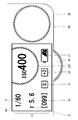
- non-contact display form As described above, when the contact of the finger to the rear command dial D1 is not detected, only the setting contents iC of the camera are displayed on the sub display 16.
- the display form of the sub display 16 when the finger contact with the rear command dial D1 is not detected is referred to as “non-contact display form”.
- information on the setting content iC of the digital camera 1 includes information on the currently set shutter speed i1, information on the currently set aperture value i2, and currently set ISO sensitivity.
- Information ISO3: International Organization for ization Standardization
- information i4 of the current number of shootable images are displayed.
- FIG. 9 shows an example in which the currently set shutter speed is 1/60 seconds, the aperture value is F5.6, the ISO sensitivity is ISO400, and the number of shootable images is 99.
- each piece of information is displayed at a determined position and at a determined size.
- the screen is divided into four equal parts and each information is displayed equally.
- FIG. 10 is a plan view showing an example of a display on the sub display when contact with the rear command dial is detected.
- a display form of the sub-display 16 when a finger contact with the rear command dial D1 is detected is referred to as a “contact display form”.
- the image image iD1 of the rear command dial D1 is constituted by an image obtained by planarly viewing a general rotary operation dial, and is constituted by an image having a circular outer shape.
- the outer peripheral portion is uneven so as to approximate the appearance of the actual rear command dial D1.
- the current setting values of items whose settings are changed by the rear command dial D1 are displayed inside (the dial portion).
- FIG. 10 shows the case where the item whose setting is changed by the rear command dial D1 is the shutter speed, and shows an example in which the current set value of the shutter speed is 1/60 seconds. In this case, as shown in FIG. 10, the image image iD1 is displayed as 1/60 inside an image having a circular outer shape.
- the image iD1 of the rear command dial D1 is displayed in a first size at a predetermined position. In the digital camera 1 of the present embodiment, it is displayed on the same axis as the rotation axis D1o of the actual rear command dial D1, and is displayed in a size smaller than the size of the actual rear command dial D1.
- the sub display display control unit 114 When causing the image image iD1 of the rear command dial D1 to appear, the sub display display control unit 114 appears while gradually increasing the diameter with the rotation axis D1o of the actual rear command dial D1 as a base point. That is, the appearance of appearing while gradually increasing is displayed as a moving image. Thereby, the user's attention can be directed to the sub display 16.
- the display layout of the camera setting contents iC is changed so as to avoid the display. That is, the display position and size are adjusted so that the information of each item is not displayed overlapping the image iD1 of the rear command dial D1. Therefore, the display of the camera setting content iC is performed in the blank area. At this time, the display position and the display size are adjusted so that the information of each item is displayed as large as possible. As a result, it is possible to avoid the camera setting contents iC and the image image iD1 of the rear command dial D1 being displayed overlapping each other.
- FIG. 11 is a plan view showing an example of a display on the sub display when contact with the rear command dial is continuously detected for a certain time or more. The same display is performed when the rear command dial D1 is rotated.
- a display form of the sub-display 16 when the contact with the rear command dial D1 is continuously detected for a predetermined time or more and when the rear command dial D1 is rotated is referred to as an “operation display form”.
- the rear command dial D1 displayed on the sub display 16 is displayed.
- the image iD1 is enlarged and displayed.
- the sub display display control unit 114 enlarges and displays the image image iD1 of the rear command dial D1 that appears on the sub display 16 to the second size. At this time, the sub display display control unit 114 enlarges the outer diameter of the image image iD1 of the rear command dial D1 to the second size while gradually increasing the outer diameter of the image iD1 of the rear command dial D1 with reference to the actual rotation axis D1o of the rear command dial D1. . That is, the state of gradually expanding is displayed as a moving image. Thereby, the user's attention can be directed to the sub display 16. This also makes it possible to clarify the relationship between the image displayed on the sub-display 16 and the actual rear command dial D1.
- the image iD1 of the rear command dial D1 enlarged to the second size has an outer diameter that substantially matches the outer diameter of the actual rear command dial D1.
- the image displayed on the sub-display 16 is an image having an arcuate outer shape obtained by extending a part of the outer periphery of the rear command dial D ⁇ b> 1 exposed from the camera body 10.
- This image is an image as if a hidden portion of the rear command dial D1 is displayed.
- the connection between the rear command dial D1 and the image iD1 displayed on the sub display 16 can be strengthened, which can contribute to intuitive operability.
- the enlargement of the image image iD1 is stopped and returned to the first size. In this case, the image is gradually reduced and returned to the first size.
- the display of the image image itself may be deleted.
- the image image iD1 of the rear command dial D1 is also rotated. In this case, the uneven portion on the outer periphery is rotated and displayed. This makes it clearer that the user is operating.
- the display layout of the camera setting content iC is changed so as to avoid the display. That is, the display position and size are adjusted so that the information of each item is not displayed overlapping the image iD1 of the rear command dial D1. Therefore, the display of the camera setting content iC is performed in the blank area. At this time, the display position and the display size are adjusted so that the information of each item is displayed as large as possible. As a result, the image iD1 of the rear command dial D1 and the setting contents iC of the camera can be prevented from overlapping each other.
- the sub display display control unit 114 switches the display of the sub display 16 based on the detection result of the finger contact with the rear command dial D1 and the rotation operation of the rear command dial D1.
- the sub display display control unit 114 controls the display of the sub display 16 based on the output from the touch sensor D1b provided in the rear command dial D1 and the output from the operation detection unit D1a. Further, the sub display display control unit 114 acquires information necessary for display, and controls the display of the sub display 16 so that the acquired information is displayed in a prescribed layout.
- the function of the sub display display control unit 114 is provided as one function of the system controller 80. That is, when the microcomputer executes a predetermined control program, the function of the sub display display control unit 114 is provided as one function of the system controller 80.
- FIG. 12 is a flowchart showing a sub-display display control processing procedure.
- the sub display display control unit 114 displays information on the sub display 16 in a non-contact display mode (step S10). That is, as shown in FIG. 9, only the camera setting contents iC are displayed on the sub-display 16.
- the sub display display control unit 114 determines whether or not a finger is touched on the rear command dial D1 based on the output of the touch sensor D1b. That is, it is determined whether or not contact with the rear command dial D1 is detected (step S11).
- the sub-display display control unit 114 determines whether the power of the digital camera 1 is turned off (step S12). If it is determined that the power of the digital camera 1 has been turned off, the process ends. On the other hand, if it is determined that the power of the digital camera 1 is not turned off, the process returns to step S11 to determine whether or not contact with the rear command dial D1 is detected (step S11). In this case, the display on the sub-display 16 is continuously displayed in the non-contact display mode.
- the sub-display display control unit 114 displays information on the sub-display 16 in the display mode at the time of contact (step S13). That is, as shown in FIG. 10, the image iD1 of the rear command dial D1 appears on the sub display 16. When the image iD1 of the rear command dial D1 appears, the image is displayed in a predetermined size (first size) while gradually increasing the diameter from the point state.
- the sub display display control unit 114 determines whether or not the finger is continuously touched to the rear command dial D1 based on the output of the touch sensor D1b. That is, it is determined whether or not detection of contact with the rear command dial D1 is continued (step S14).
- step S10 If it is determined that the contact detection is not continued, the process returns to step S10, and the display on the sub-display 16 is switched to the display in the non-contact display mode. In this case, the image iD1 of the rear command dial D1 is erased while being gradually reduced.
- the sub-display display control unit 114 next determines whether or not the rear command dial D1 has been rotated based on the output from the operation detection unit D1a. (Step S15).
- the sub-display display control unit 114 displays information on the sub-display 16 in the display format during operation (step S17). That is, as shown in FIG. 11, the image image iD1 of the rear command dial D1 that appears on the sub display 16 is enlarged. At this time, the diameter is enlarged to a predetermined size (second size) while gradually increasing the diameter.
- the sub-display display control unit 114 next determines whether or not a certain time has elapsed since the start of contact detection (step S16). That is, it is determined whether or not contact with the rear command dial D1 is continuously detected for a predetermined time or more.
- the “certain time” serving as a criterion for determination is a predetermined time, for example, 2 seconds.
- the sub display display control unit 114 counts the elapsed time from the start of contact detection.
- step S14 If it is determined that a certain time has not elapsed since the start of contact detection, the process returns to step S14, and it is determined whether or not detection of contact with the rear command dial D1 is continued. In this case, the display on the sub-display 16 is continuously displayed in the display mode at the time of contact.
- the sub-display display control unit 114 displays information on the sub-display 16 in the operation display mode (step S17). That is, as shown in FIG. 11, the image image iD1 of the rear command dial D1 that appears on the sub display 16 is enlarged. At this time, the diameter is enlarged to a predetermined size (second size) while gradually increasing the diameter. If contact with the rear command dial D1 is not detected during enlargement, the enlargement of the image iD1 is stopped. In this case, the image is gradually reduced and returned to the first size.
- the sub display display control unit 114 determines whether or not the detection of the contact with the rear command dial D1 is continued based on the output of the touch sensor D1b (step S18).
- the process returns to step S10, and the display on the sub-display 16 is switched to the display in the non-contact display mode.
- the display form may be switched, but the display form may be switched after a predetermined time has elapsed. That is, even when contact is not detected, the display mode at the time of contact may be maintained for a certain period of time, and thereafter, the display may be switched to the display mode at the time of non-contact.
- the image iD1 of the rear command dial D1 may be erased while being gradually reduced.
- the sub-display display control unit 114 determines whether the power of the digital camera 1 is turned off (step S19). If it is determined that the power of the digital camera 1 has been turned off, the process ends. On the other hand, if it is determined that the power of the digital camera 1 is not turned off, the process returns to step S18, and it is determined whether or not the detection of contact with the rear command dial D1 is continued (step S18). In this case, the display on the sub-display 16 is continuously displayed in the display format during operation.
- the display of the sub display 16 is switched based on the detection result of finger contact with the rear command dial D1 and the rotation operation of the rear command dial D1.
- the rear command dial D1 is not operated, only the setting contents iC of the camera are displayed on the sub-display 16, so that information on each item can be displayed large and good visibility can be ensured. Thereby, favorable operativity can be provided.
- the image iD1 is displayed on the sub display 16, so that setting using the rear command dial D1 can be easily performed.
- the image iD1 of the rear command dial D1 is displayed in a predetermined form on the sub display 16 when the rear command dial D1 is touched. It is easy to turn on, and even users who are using it for the first time can operate without being confused. Further, the image iD1 displayed on the sub-display 16 is composed of an image having an arcuate outer shape obtained by extending a part of the outer periphery of the rear command dial D1 exposed from the camera body 10. The connection between the display and the actual rear command dial D1 can be grasped at a glance. Thereby, favorable operativity can be provided.
- the setting contents of the camera displayed on the sub-display 16 include at least information on setting values of items set by the rear command dial D1.
- the item set by the rear command dial D1 is automatically switched according to the shooting mode
- the program shift function is assigned in the program mode, and the shutter speed priority mode is selected.
- a function for setting the shutter speed is assigned
- a function for setting the aperture value is assigned in the aperture priority mode
- a function for setting the shutter speed is assigned in the manual mode.
- the setting contents of the camera displayed on the sub display 16 include at least information on the shutter speed and the aperture value.
- the item set with the rear command dial D1 is the shutter speed.
- the shutter speed information is excluded from the information displayed as the setting contents of the camera.
- information on the aperture value, ISO sensitivity, and the number of images that can be shot is displayed as information on the camera settings.
- FIG. 13 is a plan view showing an example of a display on the sub display when contact with the rear command dial is detected continuously for a predetermined time or more. This figure shows an example in which the item set with the rear command dial D1 is the shutter speed.
- the shutter speed is set from the camera setting contents iC.
- Exclude value information That is, only the aperture value setting value information i2, the ISO sensitivity setting value information i3, and the shootable image number information i4 are displayed as the camera setting content iC.
- the camera setting content iC including information on the shutter speed setting value is displayed on the sub-display 16 (see FIG. 9).
- FIG. 14 is a plan view showing a modification of the display on the sub display when no contact with the rear command dial is detected.
- a mark mD1 serving as a base point when the image image iD1 of the rear command dial D1 appears is displayed in advance.
- the mark mD1 is configured by a figure obtained by reducing the image iD1 of the rear command dial D1.
- the mark mD1 is constituted by a substantially circular figure.
- the image image iD1 of the rear command dial D1 When making the image image iD1 of the rear command dial D1 appear, the image image iD1 is made to appear while being gradually enlarged with the mark mD1 as a base point. Thereby, the image image iD1 of the rear command dial D1 can be displayed, and the display position can be grasped in advance, thereby providing good operability. Further, since the mark mD1 is displayed in a small size, the visibility of the display of the setting content iC of the camera is not impaired.
- the image displayed as the image image iD1 of the rear command dial D1 is composed of an image having a circular outer shape, and the current setting values of the items to be changed by the rear command dial D1 are stored therein.
- the form of the image displayed as the image image iD1 of the rear command dial D1 is not limited to this.
- FIG. 15 is a plan view showing an example of a display on the sub display when contact with the rear command dial is continuously detected for a predetermined time or more.
- This figure shows another example of the image iD1 of the rear command dial D1.
- this figure shows an example in which the item set with the rear command dial D1 is the shutter speed.
- FIG. 16 is a diagram showing an example of an image when the item set with the rear command dial is the shutter speed.
- the image iD1 can be composed of an image imitating a general shutter speed dial.
- the image iD1 is composed of an image obtained by viewing a general shutter speed dial in plan view.
- a general shutter speed dial is a dial in which shutter speeds that can be selected on the dial portion on the top surface are displayed at a constant pitch on the same circumference.
- the index image iI1 is also displayed.
- the index image iI1 is displayed at the 9 o'clock position.
- the current setting is 1/60 second.
- the current setting value is highlighted and displayed with an index. That is, it is displayed in a size larger than other numerical values.
- FIG. 17 is a diagram illustrating an example of an image when the item set with the rear command dial is an aperture value.
- the image iD1 can be composed of an image imitating a general aperture value setting dial.
- the image image iD ⁇ b> 1 is composed of an image obtained by planarly viewing a general aperture value setting dial.
- a general aperture value setting dial is a dial in which aperture values that can be selected on the dial portion on the top surface are displayed at a constant pitch on the same circumference.
- FIG. 18 is a diagram illustrating an example of an image when the item set with the rear command dial is an exposure correction amount.
- the image iD1 can be composed of an image imitating a general exposure correction dial.
- the image image iD1 is composed of an image obtained by planarly viewing a general exposure correction dial.
- a general exposure correction dial is a dial in which exposure correction amounts that can be selected on the dial portion on the top surface are displayed at a constant pitch on the same circumference.
- FIG. 19 is a diagram illustrating an example of an image when the item set with the rear command dial is ISO sensitivity.
- the image iD1 can be composed of an image imitating a general ISO sensitivity dial.
- the image image iD1 is composed of an image obtained by viewing a general ISO sensitivity dial in plan view.
- a general ISO sensitivity dial is a dial in which ISO sensitivity selectable on the dial portion on the top surface is displayed at a constant pitch on the same circumference.
- the configuration of the digital camera itself is the same as that of the digital camera of the first embodiment except that the display method on the sub-display 16 is different. Therefore, only the display method (display control method) on the sub-display 16 will be described here.
- the display on the sub display 16 is controlled by the sub display display control unit 114.
- the sub display display control unit 114 switches the display of the sub display 16 based on the detection result of the finger contact with the rear command dial D1 and the rotation operation of the rear command dial D1.
- FIG. 20 is a plan view showing an example of display on the sub display when contact with the rear command dial is detected.
- a display form of the sub-display 16 when a finger contact with the rear command dial D1 is detected is referred to as a “contact display form”.
- the image image iD1 of the rear command dial D1 is composed of a circular image having the same size as the actual rear command dial D1, and set values of items set by the rear command dial D1 are displayed therein.
- FIG. 20 shows an example when the item set by the rear command dial D1 is the shutter speed, and shows an example when the current set value is 1/60 seconds.
- a portion indicated by a dashed line is a portion that appears outside the display area. That is, only a part of the image iD1 of the rear command dial D1 is displayed on the sub display 16.
- the image image iD1 of the rear command dial D1 appears from the edge of the side closest to the installation location of the rear command dial D1.
- the rear command dial D1 is provided on the back surface, so the side on the back side of the sub display 16 is the side closest to the rear command dial D1. Therefore, in the digital camera of the present embodiment, the rear command dial D1 appears from the edge of the side on the back side among the four sides constituting the edge of the sub display 16.
- the direction in which the image image iD1 of the rear command dial D1 appears is a direction orthogonal to the edge where the image image iD1 of the rear command dial D1 appears.
- the image image iD1 of the rear command dial D1 appears from the edge of the side on the back side. Therefore, the image iD1 of the rear command dial D1 gradually appears while moving (advancing) forward along the optical axis.
- the image image iD1 of the rear command dial D1 moves along a straight line passing through the actual rotation center of the rear command dial D1 and orthogonal to the side on the back side, and appears from the edge. .
- the movement of the image iD1 that gradually appears from the edge while moving in the forward direction is stopped when a certain amount is displayed.
- the movement of the image image iD1 stops when approximately 1/3 of the whole is displayed.
- the display amount at this time is defined as a first display amount. In other words, the display amount is the proportion of the entire image image iD1 that is actually displayed on the display surface of the sub-display 16.
- the image image iD1 of the rear command dial D1 gradually appears from the edge and is displayed. Thereby, the user's attention can be directed to the sub display 16.
- the display layout of the camera setting contents iC is changed so as to avoid the display. That is, the display position and size are adjusted so that the information of each item is not displayed overlapping the image iD1 of the rear command dial D1. Therefore, the display of the camera setting content iC is performed in the blank area. At this time, the display position and the display size are adjusted so that the information of each item is displayed as large as possible. As a result, it is possible to avoid the image image iD1 of the rear command dial D1 and the camera setting content iC from being displayed overlapping each other.
- information on items set by the rear command dial D1 is deleted from information on the setting contents iC of the camera. That is, the information of the shutter speed setting value is deleted from the camera setting content iC and displayed.
- FIG. 21 is a plan view showing an example of a display on the sub display when contact with the rear command dial is continuously detected for a certain time or more. The same display is performed when the rear command dial D1 is rotated.
- a display form of the sub-display 16 when the contact with the rear command dial D1 is continuously detected for a predetermined time or more and when the rear command dial D1 is rotated is referred to as an “operation display form”.
- the rear command dial D1 After the contact of the finger to the rear command dial D1 is detected, if the contact is continuously detected as it is, or if the rear command dial D1 is rotated, the rear command dial D1 that appears on the sub-display 16 is displayed.
- the image iD1 further advances forward and is displayed in a large size.
- an arc indicated by a broken line indicates a state in which the image image iD1 of the rear command dial D1 moves.
- the sub display display control unit 114 further advances the image iD1 of the rear command dial D1 that has appeared on the sub display 16 in the forward direction and stops it at a predetermined position. This position is a position displayed coaxially with the actual rear command dial D1.
- the image image iD1 of the rear command dial D1 is displayed on the sub display 16 with a second display amount larger than the first display amount by being displayed coaxially with the actual rear command dial D1.
- the image iD1 of the rear command dial D1 is composed of an image having the same size as that of the actual rear command dial D1, so that the image is displayed on the same axis as the actual rear command dial D1. Is an image having an arcuate outer shape in which a part of the outer periphery of the rear command dial D1 exposed from the camera body 10 is extended.
- the display layout of the camera setting content iC is changed so as to avoid the display. That is, the display position and size are adjusted so that the information of each item is not displayed overlapping the image iD1 of the rear command dial D1. Therefore, the display of the camera setting content iC is performed in the blank area. At this time, the display position and the display size are adjusted so that the information of each item is displayed as large as possible. As a result, it is possible to avoid the image image iD1 of the rear command dial D1 and the camera setting content iC from being displayed overlapping each other.
- the advancement of the image image iD1 is stopped and returned to the first display amount. In this case, it is gradually retracted and returned to the first display amount. Instead of returning to the first display amount, the display of the image itself may be deleted.
- the image image iD1 of the rear command dial D1 is displayed from the edge of the sub-display 16.
- good operability can be provided while ensuring good visibility with respect to the setting content iC of the camera.
- FIG. 22 is a plan view showing a modification of the display on the sub display when no contact with the rear command dial is detected.
- a part of the outer periphery of the image image iD1 of the rear command dial D1 is displayed at the position where the image image iD1 of the rear command dial D1 appears.
- the image image iD1 of the rear command dial D1 can be displayed, and the appearance position thereof can be grasped in advance, thereby providing good operability.
- the visibility of display of the setting content iC of the camera is not impaired.
- the digital camera of the present embodiment includes a lock unit that locks the rear command dial D1, and the display of the sub-display 16 is switched according to the lock status of the lock unit.
- [Constitution] 23 and 24 are a rear view and a plan view, respectively, of a third embodiment of a digital camera to which the present invention is applied.
- the digital camera 1 includes a rear command dial lock switch DL1 that locks the rear command dial D1.
- the rear command dial lock switch DL1 is an example of a lock unit.
- the rear command dial lock switch DL1 is provided in the vicinity of the rear command dial D1.
- the digital camera 1 according to the present embodiment is provided on the back surface of the camera body 10 in parallel with the rear command dial D1.
- the rear command dial lock switch DL1 is composed of a slide type switch.
- the rear command dial lock switch DL1 is provided to be slidable between a lock position and an unlock position.
- the system controller 80 is instructed to lock the rear command dial D1.
- the rear command dial lock switch DL1 is set to the unlock position, the system controller 80 is instructed to unlock the rear command dial D1.
- the system controller 80 electronically locks the rear command dial D1 when instructed to lock the rear command dial D1. That is, even if the rear command dial D1 is rotated, the operation is invalidated. In this case, the rear command dial D1 is idle.
- the electronically locked rear command dial D1 is unlocked by setting the rear command dial lock switch DL1 to the unlock position.
- the image image iD1 of the rear command dial D1 appears on the sub display 16. At this time, the image iD1 is displayed in a small first size.
- FIG. 25 is a plan view showing an example of display on the sub display when the rear command dial is locked.
- the display form of the sub-display 16 when the rear command dial D1 is locked is referred to as “display form when locked”.
- information on the setting content iC of the digital camera 1 includes information on the currently set shutter speed i1, information on the currently set aperture value i2, and currently set ISO sensitivity.
- Information i3 and information i4 on the current number of shootable images are displayed.
- FIG. 25 shows an example in which the currently set shutter speed is 1/60 seconds, the aperture value is F5.6, the ISO sensitivity is ISO400, and the number of shootable images is 99.
- each piece of information is displayed at a determined position and at a determined size.
- the screen is divided into four equal parts and each information is displayed equally.
- FIG. 26 is a plan view showing an example of a display on the sub display when the rear command dial is unlocked.
- the image iD1 of the rear command dial D1 appears on the sub display 16.
- the display form of the sub-display 16 when the rear command dial D1 is unlocked is referred to as a “display form when unlocked”.
- the display mode at the time of unlocking is the same as the display mode of the sub-display 16 when contact with the rear command dial D1 is detected in the digital camera of the first embodiment. That is, the image iD1 of the rear command dial D1 is displayed in the first size on the same axis as the rotation axis D1o of the actual rear command dial D1.
- FIG. 27 is a plan view showing an example of a display on the sub display when contact with the rear command dial is detected with the rear command dial unlocked.
- the display mode when unlocking and contacting is the same as the display mode of the sub display 16 when the rear command dial D1 is rotated in the digital camera of the first embodiment. That is, it is composed of an image having an arcuate outer shape obtained by extending a part of the outer periphery of the rear command dial D1 exposed from the camera body 10.
- FIG. 28 and FIG. 29 are flowcharts showing the processing procedure of the sub-display display control.
- the sub display display control unit 114 determines whether or not the rear command dial D1 is locked (step S30).
- the sub-display display control unit 114 displays information on the sub-display 16 in the locked display mode (step S31). That is, as shown in FIG. 25, only the setting contents iC of the camera are displayed on the sub display 16. Thereafter, the sub display display control unit 114 determines whether or not the power of the digital camera 1 is turned off (step S32). If it is determined that the power of the digital camera 1 has been turned off, the process ends. On the other hand, if it is determined that the power of the digital camera 1 is not turned off, the process returns to step S30 to determine whether or not the rear command dial D1 is locked.
- step S30 If it is determined in step S30 that the rear command dial D1 is not locked, the sub-display display control unit 114 displays information on the sub-display 16 in the unlocked display mode (step S40). That is, as shown in FIG. 26, the image iD1 of the rear command dial D1 appears on the sub-display 16. Thereafter, the sub display display control unit 114 determines the presence or absence of detection of a finger contact with the rear command dial D1 based on the output of the touch sensor D1b (step S41).
- the sub-display display control unit 114 determines whether or not the digital camera 1 is turned off (step S42). If it is determined that the power of the digital camera 1 has been turned off, the process ends. On the other hand, if it is determined that the power of the digital camera 1 is not turned off, the process returns to step S41, and it is determined whether or not a finger contact with the rear command dial D1 is detected (step S41).
- step S41 If it is determined in step S41 that the contact of the finger with the rear command dial D1 has been detected, the sub-display display control unit 114 displays information on the sub-display 16 in the unlocked and contact display mode (step S43). That is, as shown in FIG. 27, the image image iD1 of the rear command dial D1 that appears on the sub-display 16 is enlarged, and the image image iD1 of the rear command dial D1 is displayed in the second size.
- the sub display display control unit 114 determines whether or not detection of contact with the rear command dial D1 is continued (step S44).
- the sub-display display control unit 114 determines whether the power of the digital camera 1 is turned off (step S45). If it is determined that the power of the digital camera 1 has been turned off, the process ends. On the other hand, if it is determined that the power of the digital camera 1 is not turned off, the process returns to step S44, and it is determined whether or not detection of contact with the rear command dial D1 is continued (step S44).
- step S44 If it is determined in step S44 that contact with the rear command dial D1 is not continuously detected, the sub-display display control unit 114 returns to step S40 and switches the display of the sub-display 16 to the display mode when unlocked. (Step S40).
- the display of the sub display 16 is switched according to the locked state of the rear command dial D1.
- the display on the sub-display 16 is switched based on the detection result of finger contact with the rear command dial D1. If the rear command dial D1 is locked, it means that the user does not intend to use the rear command dial D1. Accordingly, in this case, by eliminating the display of the image image iD1 of the rear command dial D1 from the sub display 16, the visibility of the setting contents iC of the camera displayed on the sub display 16 can be ensured satisfactorily.
- the image image iD1 of the rear command dial D1 is displayed on the sub-display 16, so that it is possible to provide good operability when operating with the rear command dial D1. Further, the image iD1 of the rear command dial D1 is displayed small when the rear command dial D1 is not touched, so that the visibility of the setting content iC of the camera is not hindered.
- a predetermined mark is a mark serving as a base point when the image image iD1 of the rear command dial D1 appears.
- the image image iD1 of the rear command dial D1 appears with the mark as a base point.
- the image image iD1 of the rear command dial D1 may appear in the first size.
- the image iD1 of the rear command dial D1 appears in the first size when contact is detected, the contact is further detected for a certain time or when the rear command dial D1 is rotated. Then, the image iD1 of the rear command dial D1 is enlarged and displayed to the second size.
- display examples of the sub-display 16 in this case will be described with reference to FIGS.
- FIG. 30 is a plan view showing an example of a display on the sub display when a mark appears when the rear command dial is unlocked.
- the mark mD1 is constituted by a reduced figure of the image image iD1 of the rear command dial D1. Since the mark mD1 is small, the visibility of the setting content iC of the camera is not impaired.
- FIG. 31 is a plan view showing an example of a display on the sub display when a finger contact with the rear command dial is detected.
- FIG. 32 is a plan view showing an example of a sub-display display when contact is detected continuously for a certain period of time or when a rotation operation is performed.
- the image image iD1 is enlarged and the first image iD1 is enlarged. Display with a size of 2.
- the configuration of the digital camera is the same as that of the digital camera of the third embodiment except that the display method on the sub-display 16 is different. Therefore, only the display method (display control method) on the sub-display 16 will be described here.
- the display on the sub display 16 is controlled by the sub display display control unit 114.
- the sub display display control unit 114 switches the display of the sub display 16 based on the lock state of the rear command dial D1 and the detection result of the finger contact with the rear command dial D1.
- FIG. 33 is a plan view showing an example of a display on the sub display when the rear command dial is unlocked.
- FIG. 34 is a plan view showing an example of a display on the sub display when contact with the rear command dial is detected in a state where the lock of the rear command dial is released.
- the image image iD1 of the rear command dial D1 is displayed from the edge of the sub display 16.
- good operability can be provided while ensuring good visibility with respect to the setting content iC of the camera.
- FIG. 35 is a plan view showing an example of a sub-display when a part of the outer periphery of the image image of the rear command dial appears from the edge when the rear command dial is unlocked.
- FIG. 36 is a plan view showing an example of a display on the sub display when a finger contact with the rear command dial is detected.
- the image image iD1 of the rear command dial is further advanced from the edge and displayed with the first display amount.
- FIG. 37 is a plan view showing an example of a display on the sub display when contact is detected continuously for a certain time or more and when a rotation operation is performed.
- the rear command dial D1 is rotated, or when contact is continuously detected for a certain period of time, the rear command dial image iD1 is further advanced from the edge, and the second display amount is set. indicate.
- a rear command dial image is displayed on the sub display in advance.
- the display form of the rear command dial image is switched depending on whether or not a finger contact with the rear command dial is detected.
- the configuration of the digital camera itself is the same as that of the digital camera of the first embodiment except that the display method on the sub-display 16 is different. Therefore, only the display method (display control method) on the sub-display 16 will be described here.
- the display on the sub display 16 is controlled by the sub display display control unit 114.
- the sub display display control unit 114 switches the display of the sub display 16 based on the detection result of the finger contact with the rear command dial D1.
- FIG. 38 is a plan view showing an example of display on the sub display when contact with the rear command dial is not detected.
- the figure shows an example in which the item set by the rear command dial D1 is the shutter speed.
- the sub display 16 displays information on camera setting contents iC and an image iD1 of the rear command dial D1.
- information on the setting content iC of the digital camera 1 includes information on the currently set aperture value i2, information on the currently set ISO sensitivity i3, and information on the current number of shootable images i4. , And information i5 on the currently set shooting mode is displayed.
- the information on the camera setting contents iC does not include the shutter speed information because the item set by the rear command dial D1 is the shutter speed.
- information on items excluding items set by the rear command dial D1 is displayed. Therefore, for example, when the item set by the rear command dial D1 is an aperture value, information on the aperture value is removed and information on the setting content iC of the camera is displayed.
- FIG. 38 shows an example in which the currently set shooting mode is shutter speed priority, the aperture value is F5.6, the ISO sensitivity is ISO400, and the number of shootable images is 99.
- an icon prepared for each mode is displayed. As shown in FIG. 38, the icon displays one alphabetic character representing each mode in a rectangular frame. For example, the alphabet is displayed as P in the program mode, S in the shutter speed priority mode, A in the aperture priority mode, and M in the manual mode.
- the camera setting content iC is displayed in a specified layout at the margin position.
- the image image iD1 of the rear command dial D1 is configured by an image having an arcuate outer shape obtained by extending a part of the outer periphery of the rear command dial D1 exposed from the camera body 10. This image is an image that complements the hidden portion of the rear command dial D1.
- FIG. 39 is a plan view showing an example of a display on the sub display when contact with the rear command dial is detected.
- the image iD1 of the rear command dial D1 when a finger contact with the rear command dial D1 is detected is configured with an image indicating that the setting can be changed by operating the rear command dial D1. .
- the image iD1 is composed of an image obtained by planarly viewing a general shutter speed dial.
- the user can change the setting by operating the rear command dial D1 from the display of the sub-display 16. Can be grasped. Further, the user's attention can be directed to the sub-display 16 by switching the display form.
- the rear command dial D1 is operated from the display on the sub display 16. By doing so, it is possible to easily grasp that the setting can be changed.
- the display form of the image image iD1 of the rear command dial D1 displayed on the sub display 16 is switched.
- the setting can be easily performed while using the sub display 16.
- the user's attention is directed by switching the display, even a first-time user can operate without being confused.
- FIG. 40 is a plan view showing another example of display on the sub display when contact with the rear command dial is detected.
- the internal set value is displayed statically, and when the contact is detected, the internal set value is displayed blinking.
- FIG. 41 is a plan view showing another example of the display on the sub-display when contact with the rear command dial is not detected.
- the current set value is displayed in parentheses in the image iD1 of the rear command dial D1.
- the parentheses are removed when contact with the rear command dial is detected. That is, the display shown in FIG.
- the display mode of the image image iD1 of the rear command dial D1 is switched when the contact of the finger with the rear command dial D1 is detected.
- the rear command dial D1 is rotated.
- the display form of the image image iD1 of the rear command dial D1 may be switched.
- a plurality of operation dials can be provided.
- the camera body is provided with a plurality of operation dials.
- Consstitution 42, 43, and 44 are a front view, a rear view, and a plan view of a digital camera according to the sixth embodiment, respectively.
- the digital camera 1 includes a plurality of operation dials in the vicinity of the sub display 16. Specifically, a rear command dial D1 is provided on the back of the camera body 10 as a first operation dial. In addition, a front command dial D2 is provided in front of the camera body 10 as a second operation dial. Furthermore, a top command dial D3 is provided on the top of the camera body 10 as a third operation dial. Both are provided near the sub-display 16.
- the vicinity means a distance relationship such that the sub display 16 and the operation dial are arranged adjacent to each other as shown in FIGS.
- each operation dial in the vicinity of the sub-display 16 it is possible to improve the relationship between the two and provide better operability. That is, since the setting can be confirmed in the immediate vicinity of the operation dial, it is possible to reduce the movement of the line of sight and provide good operability without stress. Intuitive operation can also be realized.
- the rear command dial D1 is the same as the rear command dial D1 of the first embodiment.
- the rear command dial D ⁇ b> 1 is provided behind the sub display 16.
- the front command dial D2 is provided at the upper end of the grip 22.
- the front command dial D ⁇ b> 2 is provided in front of the sub display 16.
- the configuration of the front command dial D2 is the same as the configuration of the rear command dial D1. That is, it can be rotated in both directions and has a click mechanism. The contact is detected by a touch sensor.
- the top command dial D3 is provided at the end of the camera body 10 on the grip side.
- the top surface command dial D3 is provided on the right side with respect to the sub display 16.
- the top command dial D3 has the same configuration as the rear command dial D1 except that the top command dial D3 is provided so as to be exposed entirely. That is, it can be rotated in both directions and has a click mechanism. The contact is detected by a touch sensor.
- the configuration other than that having a plurality of operation dials is the same as that of the digital camera of the first embodiment. Therefore, the description is omitted.
- ⁇ Sub display display ⁇ The display on the sub-display 16 is switched according to detection of contact with each operation dial and operation of each operation dial. Hereinafter, switching of the display of the sub display 16 will be described.
- a function for setting the shutter speed is assigned to the rear command dial D1
- a function for setting the ISO sensitivity is assigned to the front command dial D2
- a function for setting the exposure correction amount to the top command dial D3 is assigned to the rear command dial D1
- a function for setting the ISO sensitivity is assigned to the front command dial D2
- a function for setting the exposure correction amount is assigned to the top command dial D3. The case where it is assigned will be described as an example.
- FIG. 45 is a plan view showing an example of display on the sub display when contact with all the operation dials is not detected.
- information on the setting content iC of the digital camera 1 includes information on the currently set shutter speed i1, information on the currently set aperture value i2, and currently set ISO sensitivity.
- each piece of information is displayed at a determined position and at a determined size.
- FIG. 46 is a plan view showing an example of sub-display display when contact with the rear command dial is detected. .
- the image iD1 of the rear command dial D1 is composed of an image simulating the rear command dial D1, and is composed of a circular image. Inside the image image iD1 of the rear command dial D1, setting values of items whose settings are changed by the rear command dial D1 are displayed.
- the rear command dial D1 is assigned a function for setting the shutter speed. Therefore, the currently set shutter speed is displayed inside the image iD1 of the rear command dial D1.
- FIG. 46 shows an example in which the currently set shutter speed is 1/60 seconds.
- the image image iD1 of the rear command dial D1 appears from the edge near the rear command dial D1.
- the rear command dial D1 is disposed rearward with respect to the sub display 16. Therefore, the image image iD1 of the rear command dial D1 appears from the rear edge (rear side) of the sub display 16.
- the image iD1 of the rear command dial D1 appears with a first display amount from the rear edge. This display amount is an amount for which about 1/3 of the entire display is displayed.
- the display layout of the camera setting content iC is changed so as to avoid the display. That is, the display position and size are adjusted so that the information of each item is not displayed overlapping the image iD1 of the rear command dial D1. Therefore, the display of the camera setting content iC is performed in the blank area. At this time, the display position and the display size are adjusted so that the information of each item is displayed as large as possible.
- the item displayed as the camera setting content iC is also switched. That is, the information of the item set by the rear command dial D1 is removed, and the camera setting content iC is displayed. Therefore, in the case of this example, information on the setting value of the shutter speed is removed, and the setting content iC of the camera is displayed. Thereby, the duplicate display can be eliminated.
- FIG. 47 is a plan view showing an example of a display on the sub-display when contact with the rear command dial is continuously detected for a predetermined time or more. The same display is performed when the rear command dial D1 is rotated.
- FIG. 48 is a plan view showing an example of sub-display display when contact with the front command dial is detected. .
- the image iD2 of the front command dial D2 is composed of an image simulating the front command dial D2, and is composed of a circular image. Inside the image iD2 of the front command dial D2, setting values of items whose settings are changed by the front command dial D2 are displayed.
- FIG. 48 shows an example in which the currently set ISO sensitivity is ISO400.
- the image iD2 of the front command dial D2 appears from an edge near the front command dial D2.
- the front command dial D2 is disposed in front of the sub display 16. Therefore, the image image iD2 of the front command dial D2 appears from the front edge (front side) of the sub display 16.
- the image iD2 of the front command dial D2 appears with the first display amount from the front edge. This display amount is an amount for which about 1/3 of the entire display is displayed.
- the display layout of the camera setting contents iC is changed so as to avoid the display. That is, the display position and size are adjusted so that the information of each item is not displayed overlapping the image iD2 of the front command dial D2. Therefore, the display of the camera setting content iC is performed in the blank area. At this time, the display position and the display size are adjusted so that the information of each item is displayed as large as possible.
- the item displayed as the camera setting content iC is also switched. That is, the information of the item set by the front command dial D2 is removed, and the camera setting content iC is displayed. Therefore, in the case of this example, ISO sensitivity information is removed and the camera setting content iC is displayed. Thereby, the duplicate display can be eliminated.
- FIG. 49 is a plan view showing an example of a display on the sub-display when contact with the front command dial is continuously detected for a predetermined time or more. A similar display is obtained when the front command dial D2 is rotated.
- FIG. 50 is a plan view showing an example of display on the sub-display when contact with the top command dial is detected. It is.
- the image iD3 of the top surface command dial D3 is composed of an image simulating the top surface command dial D3, and is composed of a circular image. Inside the image image iD3 of the top surface command dial D3, setting values of items whose settings are changed by the top surface command dial D3 are displayed.
- FIG. 50 shows an example in which the currently set exposure correction amount is +2.
- the image image iD3 of the top surface command dial D3 appears from the edge near the top surface command dial D3.
- the top command dial D3 is disposed on the right side with respect to the sub display 16. Accordingly, the image image iD3 of the top command dial D3 appears from the right edge (right side) of the sub-display 16.
- the image iD3 of the top command dial D3 appears with the first display amount from the right edge. This display amount is an amount for which about 1/3 of the entire display is displayed.
- the display layout of the camera setting content iC is changed so as to avoid the display. That is, the display position and size are adjusted so that the information of each item is not displayed overlapping the image image iD3 of the top command dial D3. Therefore, the display of the camera setting content iC is performed in the blank area. At this time, the display position and the display size are adjusted so that the information of each item is displayed as large as possible.
- the image iD3 of the top command dial D3 appears from the edge of the sub-display 16
- the item displayed as the camera setting content iC is also switched. That is, the information of the item set by the top command dial D3 is removed, and the camera setting content iC is displayed. Therefore, in the case of this example, the exposure correction amount information is removed and the camera setting content iC is displayed. Thereby, the duplicate display can be eliminated.
- FIG. 51 is a plan view showing an example of a display on the sub-display when contact with the top command dial is detected continuously for a predetermined time or more. A similar display is also obtained when the top command dial D3 is rotated.
- the top surface that appears from the edge of the sub display 16 is displayed.
- the image iD3 of the surface command dial D3 is further displayed from the edge.
- the display of the sub-display 16 is switched according to the contact or operation of each operation dial.
- the sub-display configuring the display unit is configured by a reflective LCD, but the display configuring the display unit is not limited to this.
- the display can be configured by a self-luminous display such as an electronic paper, a memory liquid crystal display, and an organic EL display (EL: ElectroLuminescent).
- Electrode paper is a thin display with the same level of thinness and visibility as paper, and means that the display content can be rewritten.
- the memory liquid crystal display is a liquid crystal display having a function capable of maintaining the contents displayed on the screen even when the power is turned off. Both can ensure good visibility even in bright surroundings. Even when the camera is turned off, the display on the display unit can be confirmed.
- the sub-display is composed of an LCD, good visibility can be ensured even in a bright environment by configuring it with a reflective LCD.
- a display is comprised with reflection type LCD, it is preferable to provide illumination.
- the operation dial is electronically locked, but may be mechanically locked.
- the method for instructing the lock and unlocking is not limited to the one in the above embodiment.
- locking and unlocking may be instructed by the pushing operation.
- the operation dial When the operation dial is built in the camera body and a part of the outer periphery thereof is exposed from the camera body, the operation dial may be provided with a function of pressing operation.
- the pressing operation is an operation of pushing the operation dial in a direction orthogonal to the axis.
- an operation dial is provided with a press operation function, it is good also as a structure which switches the display of a sub display according to press operation similarly to the case where it is rotated.
- a touch sensor is used as means for detecting contact with the operation dial, but means for detecting contact with the operation dial is not limited to this.
- a configuration may be adopted in which the contact of the finger to the operation dial is indirectly detected by detecting that the finger has approached a certain distance from the operation dial by a non-contact type sensor.
- FIG. 52 is a rear view of a digital camera provided with a sensor for detecting the proximity of a finger to the rear command dial.
- a sensor SD1 for detecting the proximity of a finger is provided in the vicinity of the rear command dial D1.
- the sensor SD1 is composed of a proximity sensor, for example.
- the method of the proximity sensor may be any method such as an induction type, a capacitance type, an ultrasonic type, an electromagnetic wave type, and an infrared type.
- the sensor SD1 is turned on when a finger approaches a certain distance. Therefore, by detecting that the sensor SD1 is turned on, it is possible to detect that a finger has approached the rear command dial D1.
- the present invention is applied to an interchangeable lens camera has been described as an example.
- the present invention can be similarly applied to a lens integrated camera.
- the present invention is applied to a non-reflex type camera has been described as an example.
- the present invention can be similarly applied to a reflex type camera.
Abstract
The present invention provides an easy to operate camera and a display control method thereof. Finger contact with a rear command dial D1 is detected. When finger contact with the rear command dial D1 is not detected, only the content of camera settings is displayed on a sub-display 16 provided near the rear command dial D1. When finger contact with the rear command dial D1 is detected, an image picture of the rear command dial D1 is displayed in a first size on the sub-display 16. When finger contact with the rear command dial D1 is detected continuously for a fixed time or more, or when the rear command dial D1 is operated, an image picture of the rear command dial D1 is displayed in an enlarged second size.
Description
本発明は、カメラボディに表示部および操作ダイヤルを備えたカメラ、及び、その表示制御方法に関する。
The present invention relates to a camera provided with a display unit and an operation dial on a camera body, and a display control method thereof.
カメラボディの天面(いわゆる軍艦部)に表示部を備え、その表示部にシャッタースピード、絞り値などの設定内容を表示するカメラが知られている。
A camera is known that has a display on the top of the camera body (so-called warship), and displays settings such as shutter speed and aperture value on the display.
また、カメラボディに回転式の操作ダイヤルを備え、その操作ダイヤルによって各種設定を行うカメラが知られている。
In addition, there is known a camera that has a rotary operation dial on the camera body and performs various settings using the operation dial.
特許文献1には、自己照明型の第1の表示部と外光反射型の第2の表示部とを備えたカメラが記載されており、第1の表示部をカメラボディの背面に配置し、かつ、第2の表示部をカメラボディの天面に配置することが記載されている。また、特許文献1には、第1の表示部に撮影画像を表示し、かつ、第2の表示部にカメラの設定内容を表示すること、第2の表示部に備えられた照明が点灯されると、第2の表示部に表示されている情報の内容と同一の内容が第1の表示部に表示されること、及び、カメラボディの天面に備えられた操作ダイヤルのイメージ画像が第1の表示部に表示されることが記載されている。
Patent Document 1 describes a camera including a first display unit of a self-illumination type and a second display unit of an external light reflection type, and the first display unit is disposed on the back of the camera body. In addition, it is described that the second display unit is arranged on the top surface of the camera body. Further, in Patent Document 1, a photographed image is displayed on the first display unit, and the setting content of the camera is displayed on the second display unit, and the illumination provided in the second display unit is turned on. Then, the same content as the information displayed on the second display unit is displayed on the first display unit, and the image of the operation dial provided on the top surface of the camera body is displayed on the first display unit. 1 is displayed on the display unit.
また、特許文献2には、カメラボディの天面に操作ダイヤルを備え、その操作ダイヤルのロックを解除すると、操作ダイヤルのイメージ画像が、カメラボディの背面に備えられた表示部に表示されるカメラが記載されている。
Patent Document 2 discloses a camera in which an operation dial is provided on the top surface of the camera body, and when the operation dial is unlocked, an image of the operation dial is displayed on a display unit provided on the back of the camera body. Is described.
更に、特許文献3には、カメラボディの天面に操作ダイヤルを備え、その操作ダイヤルへの接触が検出されると、操作ダイヤルのイメージ画像が、カメラボディの背面に備えられた表示部に表示されるカメラが記載されている。
Furthermore, in Patent Document 3, an operation dial is provided on the top surface of the camera body, and when contact with the operation dial is detected, an image of the operation dial is displayed on a display unit provided on the back surface of the camera body. The camera to be described is described.
しかしながら、従来の構成は、いずれも操作ダイヤルから離れた表示部にイメージ画像が表示されるため、操作のための視線移動が多くなり、操作性がよくないという欠点がある。また、操作ダイヤルと表示部との結び付きが弱く、操作に戸惑いを与えるという欠点もある。
However, each of the conventional configurations has a drawback in that an image is displayed on a display unit that is distant from the operation dial, so that the line of sight movement for the operation increases and the operability is not good. In addition, the connection between the operation dial and the display unit is weak, and there is a disadvantage that the operation is confused.
本発明は、このような事情に鑑みてなされたもので、操作性のよいカメラ、及び、その表示制御方法を提供することを目的とする。
The present invention has been made in view of such circumstances, and an object thereof is to provide a camera with good operability and a display control method thereof.
上記課題を解決するための手段は、次のとおりである。
Measures for solving the above problems are as follows.
(1)表示部と、表示部の近傍に備えられる回転式の操作ダイヤルと、操作ダイヤルへの指の接触又は近接を検出する検出部と、表示部の表示を制御する表示制御部と、を備え、表示制御部は、カメラの設定内容を表示部に表示し、操作ダイヤルへの指の接触又は近接が検出された場合は、操作ダイヤルのイメージ画像を第1のサイズで表示部に出現させ、操作ダイヤルへの指の接触又は近接が一定時間以上継続して検出された場合、あるいは、操作ダイヤルが操作された場合は、表示部に出現させた操作ダイヤルのイメージ画像を第2のサイズまで拡大させて表示する、カメラ。
(1) a display unit, a rotary operation dial provided in the vicinity of the display unit, a detection unit that detects contact or proximity of a finger to the operation dial, and a display control unit that controls display of the display unit The display control unit displays the setting contents of the camera on the display unit, and when contact or proximity of a finger to the operation dial is detected, causes the image image of the operation dial to appear on the display unit in the first size. When the contact or proximity of the finger to the operation dial is continuously detected for a certain period of time or when the operation dial is operated, the image of the operation dial displayed on the display unit is displayed up to the second size. A camera that displays an enlarged image.
本態様によれば、操作ダイヤルに指が接触又は近接すると、表示部の表示が切り替えられる。操作ダイヤルに指が接触又は近接していない場合、表示部にはカメラの設定内容が表示される。これにより、表示部の表示からカメラの設定状況を確認できる。操作ダイヤルに指が接触又は近接すると、表示部に操作ダイヤルのイメージ画像が出現する。これにより、操作ダイヤルのイメージ画像が表示部に表示され得ることを予見できる。操作ダイヤルへの指の接触又は近接が一定時間以上継続して行われると、あるいは、操作ダイヤルが操作されると、表示部に出現した操作ダイヤルのイメージ画像が拡大して表示される。これにより、操作ダイヤルを操作する際、良好な操作性を提供できる。
According to this aspect, when the finger contacts or approaches the operation dial, the display on the display unit is switched. When the finger is not in contact with or close to the operation dial, the setting content of the camera is displayed on the display unit. Thereby, the setting status of the camera can be confirmed from the display on the display unit. When a finger contacts or approaches the operation dial, an image of the operation dial appears on the display unit. Thereby, it can be foreseen that the image of the operation dial can be displayed on the display unit. When the finger touches or approaches the operation dial for a certain period of time or when the operation dial is operated, the image image of the operation dial that appears on the display unit is enlarged and displayed. Thereby, when operating an operation dial, favorable operativity can be provided.
(2)表示制御部は、あらかじめ基点となるマークを表示部に表示し、操作ダイヤルへの指の接触又は近接が検出された場合は、マークを基点に操作ダイヤルのイメージ画像を拡大させて、表示部に第1のサイズで出現させる、上記(1)のカメラ。
(2) The display control unit displays a mark as a base point in advance on the display unit, and when contact or proximity of a finger to the operation dial is detected, the image image of the operation dial is enlarged based on the mark, The camera according to (1), wherein the camera appears on the display unit in a first size.
本態様によれば、操作ダイヤルのイメージ画像を出現させる際の基点となるマークが、あらかじめ表示部に表示される。操作ダイヤルのイメージ画像を出現させる場合は、そのマークを基点に操作ダイヤルのイメージ画像を拡大させて、表示部に出現させる。これにより、操作ダイヤルのイメージ画像が表示される位置を予見でき、より良好な操作性を提供できる。
According to this aspect, the mark that becomes the base point when the image image of the operation dial appears is displayed in advance on the display unit. When the image image of the operation dial appears, the image image of the operation dial is enlarged with the mark as a base point and appears on the display unit. Thereby, the position where the image image of the operation dial is displayed can be predicted, and better operability can be provided.
(3)表示部と、表示部の近傍に備えられる回転式の操作ダイヤルと、操作ダイヤルへの指の接触又は近接を検出する検出部と、表示部の表示を制御する表示制御部と、操作ダイヤルをロックするロック部と、を備え、表示制御部は、カメラの設定内容を表示部に表示し、操作ダイヤルのロックが解除された場合は、操作ダイヤルのイメージ画像を第1のサイズで表示部に出現させ、操作ダイヤルのロックが解除された状態で操作ダイヤルへの指の接触又は近接が検出された場合は、表示部に出現させた操作ダイヤルのイメージ画像を第2のサイズまで拡大させて表示する、カメラ。
(3) a display unit, a rotary operation dial provided near the display unit, a detection unit that detects contact or proximity of a finger to the operation dial, a display control unit that controls display on the display unit, and an operation A lock unit that locks the dial, and the display control unit displays the setting contents of the camera on the display unit, and displays the image of the operation dial in the first size when the operation dial is unlocked. When the contact or proximity of the finger to the operation dial is detected with the operation dial unlocked, the image of the operation dial that appears on the display unit is enlarged to the second size. Display the camera.
本態様によれば、操作ダイヤルをロックする動作、及び、ロックを解除する動作によって、表示部の表示が切り替えられる。また、操作ダイヤルのロックを解除した場合は、操作ダイヤルへの指の接触又は近接によって、表示部の表示が切り替えられる。操作ダイヤルがロックされている場合、表示部にはカメラの設定内容が表示される。これにより、表示部の表示からカメラの設定状況を確認できる。操作ダイヤルのロックが解除されると、表示部に操作ダイヤルのイメージ画像が出現する。これにより、操作ダイヤルのイメージ画像が表示部に表示され得ることを予見できる。ロックが解除された操作ダイヤルに指が接触又は近接すると、表示部に出現した操作ダイヤルのイメージ画像が拡大して表示される。これにより、操作ダイヤルを操作する際、良好な操作性を提供できる。
According to this aspect, the display on the display unit is switched by the operation of locking the operation dial and the operation of releasing the lock. When the lock of the operation dial is released, the display on the display unit is switched by the contact or proximity of the finger to the operation dial. When the operation dial is locked, the setting contents of the camera are displayed on the display unit. Thereby, the setting status of the camera can be confirmed from the display on the display unit. When the operation dial is unlocked, an image of the operation dial appears on the display unit. Thereby, it can be foreseen that the image of the operation dial can be displayed on the display unit. When a finger touches or comes close to the unlocked operation dial, an image of the operation dial that appears on the display unit is enlarged and displayed. Thereby, when operating an operation dial, favorable operativity can be provided.
(4)表示制御部は、あらかじめ基点となるマークを表示部に表示し、操作ダイヤルのロックが解除された場合は、マークを基点に操作ダイヤルのイメージ画像を拡大させて、表示部に第1のサイズで出現させる、上記(3)のカメラ。
(4) The display control unit displays a mark as a base point in advance on the display unit, and when the lock of the operation dial is released, the image image of the operation dial is enlarged using the mark as a base point, and the display unit displays the first image on the display unit. The camera according to (3), which is caused to appear at a size of.
本態様によれば、操作ダイヤルのイメージ画像を出現させる際の基点となるマークが、あらかじめ表示部に表示される。操作ダイヤルのイメージ画像を出現させる場合は、そのマークを基点に操作ダイヤルのイメージ画像を拡大させて、表示部に出現させる。これにより、操作ダイヤルのイメージ画像が表示される位置を予見でき、より良好な操作性を提供できる。
According to this aspect, the mark that becomes the base point when the image image of the operation dial appears is displayed in advance on the display unit. When the image image of the operation dial appears, the image image of the operation dial is enlarged with the mark as a base point and appears on the display unit. Thereby, the position where the image image of the operation dial is displayed can be predicted, and better operability can be provided.
(5)操作ダイヤルは、カメラボディに内蔵され、外周の一部がカメラボディの外表面に露出して配置され、表示部は、操作ダイヤルに重ねて配置され、操作ダイヤルのイメージ画像は、第2のサイズまで拡大して表示されると、カメラボディから露出した操作ダイヤルの外周の一部を延長した円弧状の外形形状を有する画像で構成される、上記(1)から(4)のいずれか一のカメラ。
(5) The operation dial is built in the camera body, a part of the outer periphery is arranged to be exposed on the outer surface of the camera body, the display unit is arranged to overlap the operation dial, and the image image of the operation dial is Any of the above (1) to (4), which is composed of an image having an arcuate outer shape obtained by extending a part of the outer periphery of the operation dial exposed from the camera body. Or one camera.
本態様によれば、操作ダイヤルのイメージ画像を第2のサイズまで拡大すると、所定の外形形状を有する画像となる。すなわち、カメラボディから露出した操作ダイヤルの外周の一部を延長した円弧状の外形形状を有する画像となる。この画像は、操作ダイヤルの隠れた部分を表示しているかのような画像となる。これにより、操作ダイヤルと表示部に表示されるイメージ画像との結び付きを強めることができ、より良好な操作性を提供できる。
According to this aspect, when the image image of the operation dial is enlarged to the second size, an image having a predetermined outer shape is obtained. That is, the image has an arcuate outer shape obtained by extending a part of the outer periphery of the operation dial exposed from the camera body. This image is an image as if a hidden portion of the operation dial is displayed. Thereby, the connection between the operation dial and the image displayed on the display unit can be strengthened, and better operability can be provided.
(6)表示制御部は、操作ダイヤルのイメージ画像を第2のサイズまで拡大させて表示する場合、操作ダイヤルのイメージ画像を徐々に拡大させて表示し、拡大中に操作ダイヤルへの指の接触又は近接が検出されなくなった場合、操作ダイヤルのイメージ画像の表示を消去、又は、第1のサイズまで徐々に縮小させる、上記(1)から(5)のいずれか一のカメラ。
(6) When the image of the operation dial is enlarged to the second size and displayed, the display control unit gradually enlarges and displays the image of the operation dial, and a finger touches the operation dial during the enlargement. Alternatively, the camera according to any one of (1) to (5), wherein when the proximity is no longer detected, the display of the image on the operation dial is deleted or gradually reduced to the first size.
本態様によれば、操作ダイヤルのイメージ画像が徐々に拡大しながら第2のサイズで表示される。これにより、表示部に表示される操作ダイヤルのイメージ画像と実際の操作ダイヤルとの関連性をより明確にできる。拡大中に操作ダイヤルへの指の接触又は近接が検出されなくなった場合は、表示部への操作ダイヤルのイメージ画像の表示が消去される。又は、第1のサイズまで徐々に縮小される。
According to this aspect, the image of the operation dial is displayed in the second size while being gradually enlarged. Thereby, the relevance between the image of the operation dial displayed on the display unit and the actual operation dial can be clarified. When the contact or proximity of the finger to the operation dial is not detected during the enlargement, the display of the image image of the operation dial on the display unit is deleted. Or, it is gradually reduced to the first size.
(7)表示部と、表示部の近傍に備えられる回転式の操作ダイヤルと、操作ダイヤルへの指の接触又は近接を検出する検出部と、表示部の表示を制御する表示制御部と、を備え、表示制御部は、カメラの設定内容を表示部に表示し、操作ダイヤルへの指の接触又は近接が検出された場合は、操作ダイヤルのイメージ画像を第1の表示量で表示部の縁から出現させ、操作ダイヤルへの指の接触又は近接が一定時間以上継続して検出された場合、あるいは、操作ダイヤルが操作された場合は、第1の表示量で表示部の縁から出現させた操作ダイヤルのイメージ画像を第1の表示量よりも多い第2の表示量で表示する、カメラ。
(7) a display unit, a rotary operation dial provided in the vicinity of the display unit, a detection unit that detects contact or proximity of a finger to the operation dial, and a display control unit that controls display of the display unit The display control unit displays the setting contents of the camera on the display unit, and when contact or proximity of a finger to the operation dial is detected, the image image of the operation dial is displayed with the first display amount at the edge of the display unit. When the contact or proximity of the finger to the operation dial is continuously detected for a certain period of time or when the operation dial is operated, the first display amount appears from the edge of the display unit. A camera that displays an image of an operation dial with a second display amount larger than the first display amount.
本態様によれば、操作ダイヤルに指が接触又は近接すると、表示部の表示が切り替えられる。操作ダイヤルに指が接触又は近接していない場合、表示部にはカメラの設定内容が表示される。これにより、表示部の表示からカメラの設定状況を確認できる。操作ダイヤルに指が接触又は近接すると、操作ダイヤルのイメージ画像が表示部の縁から出現する。これにより、操作ダイヤルのイメージ画像が表示部に表示され得ることを予見できる。操作ダイヤルへの指の接触又は近接が一定時間以上継続して行われると、あるいは、操作ダイヤルが操作されると、表示部の縁から現れた操作ダイヤルのイメージ画像が更に大きく表示される。これにより、操作ダイヤルを操作する際、良好な操作性を提供できる。
According to this aspect, when the finger contacts or approaches the operation dial, the display on the display unit is switched. When the finger is not in contact with or close to the operation dial, the setting content of the camera is displayed on the display unit. Thereby, the setting status of the camera can be confirmed from the display on the display unit. When a finger contacts or approaches the operation dial, an image of the operation dial appears from the edge of the display unit. Thereby, it can be foreseen that the image of the operation dial can be displayed on the display unit. When contact or proximity of the finger to the operation dial is continuously performed for a certain time or more, or when the operation dial is operated, an image of the operation dial that appears from the edge of the display unit is displayed larger. Thereby, when operating an operation dial, favorable operativity can be provided.
(8)表示部と、表示部の近傍に備えられる回転式の操作ダイヤルと、操作ダイヤルへの指の接触又は近接を検出する検出部と、表示部の表示を制御する表示制御部と、操作ダイヤルをロックするロック部と、を備え、表示制御部は、カメラの設定内容を表示部に表示し、操作ダイヤルのロックが解除された場合は、操作ダイヤルのイメージ画像を第1の表示量で表示部の縁から出現させ、操作ダイヤルのロックが解除された状態で操作ダイヤルへの指の接触又は近接が検出された場合は、第1の表示量で表示部の縁から出現させた操作ダイヤルのイメージ画像を第1の表示量よりも多い第2の表示量で表示する、カメラ。
(8) a display unit, a rotary operation dial provided near the display unit, a detection unit that detects contact or proximity of a finger to the operation dial, a display control unit that controls display of the display unit, and an operation A lock unit that locks the dial, and the display control unit displays the setting contents of the camera on the display unit, and when the operation dial is unlocked, the image image of the operation dial is displayed with the first display amount. The operation dial that appears from the edge of the display unit and appears from the edge of the display unit with the first display amount when contact or proximity of the finger to the operation dial is detected with the lock of the operation dial unlocked A camera that displays an image of the second display amount larger than the first display amount.
本態様によれば、操作ダイヤルをロックする動作、及び、ロックを解除する動作によって、表示部の表示が切り替えられる。また、操作ダイヤルのロックを解除した場合は、操作ダイヤルへの指の接触又は近接によって、表示部の表示が切り替えられる。操作ダイヤルがロックされている場合、表示部にはカメラの設定内容が表示される。これにより、表示部の表示からカメラの設定状況を確認できる。操作ダイヤルのロックが解除されると、操作ダイヤルのイメージ画像が表示部の縁から出現する。これにより、操作ダイヤルのイメージ画像が表示部に表示され得ることを予見できる。ロックが解除された操作ダイヤルに指が接触又は近接すると、表示部の縁から現れた操作ダイヤルのイメージ画像が更に大きく表示される。これにより、操作ダイヤルを操作する際、良好な操作性を提供できる。
According to this aspect, the display on the display unit is switched by the operation of locking the operation dial and the operation of releasing the lock. When the lock of the operation dial is released, the display on the display unit is switched by the contact or proximity of the finger to the operation dial. When the operation dial is locked, the setting contents of the camera are displayed on the display unit. Thereby, the setting status of the camera can be confirmed from the display on the display unit. When the operation dial is unlocked, an image of the operation dial appears from the edge of the display unit. Thereby, it can be foreseen that the image of the operation dial can be displayed on the display unit. When a finger touches or comes close to the unlocked operation dial, the image of the operation dial that appears from the edge of the display unit is displayed larger. Thereby, when operating an operation dial, favorable operativity can be provided.
(9)操作ダイヤルは、カメラボディに内蔵され、外周の一部がカメラボディの外表面に露出して配置され、表示部は、操作ダイヤルに重ねて配置され、操作ダイヤルのイメージ画像は、第2の表示量で表示されると、カメラボディから露出した操作ダイヤルの外周の一部を延長した円弧状の外形形状を有する画像で構成される、上記(7)又は(8)のカメラ。
(9) The operation dial is built in the camera body, a part of the outer periphery is arranged to be exposed on the outer surface of the camera body, the display unit is arranged to overlap the operation dial, and the image image of the operation dial is The camera according to (7) or (8), which is configured by an image having an arcuate outer shape obtained by extending a part of the outer periphery of the operation dial exposed from the camera body when displayed at a display amount of 2.
本態様によれば、操作ダイヤルのイメージ画像を第2の表示量で表示すると、所定の外形形状を有する画像となる。すなわち、カメラボディから露出した操作ダイヤルの外周の一部を延長した円弧状の外形形状を有する画像となる。この画像は、操作ダイヤルの隠れた部分を表示しているかのような画像となる。これにより、操作ダイヤルと表示部に表示されるイメージ画像との結び付きを強めることができ、より良好な操作性を提供できる。
According to this aspect, when the image image of the operation dial is displayed with the second display amount, the image has a predetermined outer shape. That is, the image has an arcuate outer shape obtained by extending a part of the outer periphery of the operation dial exposed from the camera body. This image is an image as if a hidden portion of the operation dial is displayed. Thereby, the connection between the operation dial and the image displayed on the display unit can be strengthened, and better operability can be provided.
(10)表示制御部は、操作ダイヤルのイメージ画像を第2の表示量で表示する場合、操作ダイヤルのイメージ画像を表示部の縁から徐々に進出させて表示し、進出中に操作ダイヤルへの指の接触又は近接が検出されなくなった場合、操作ダイヤルのイメージ画像の表示を消去、又は、第1の表示量まで徐々に退避させる、上記(7)から(9)のいずれか一のカメラ。
(10) When displaying the image image of the operation dial at the second display amount, the display control unit displays the image image of the operation dial by gradually advancing from the edge of the display unit. The camera according to any one of (7) to (9), wherein when the finger contact or proximity is no longer detected, the display of the image image of the operation dial is erased or gradually retracted to the first display amount.
本態様によれば、操作ダイヤルのイメージ画像が表示部の縁から徐々に進出しながら第2の表示量で表示される。これにより、表示部に表示される操作ダイヤルのイメージ画像と実際の操作ダイヤルとの関連性をより明確にできる。進出中に操作ダイヤルへの指の接触又は近接が検出されなくなった場合は、表示部への操作ダイヤルのイメージ画像の表示が消去される。又は、第1の表示量まで徐々に退避する。
According to this aspect, the image image of the operation dial is displayed in the second display amount while gradually advancing from the edge of the display unit. Thereby, the relevance between the image of the operation dial displayed on the display unit and the actual operation dial can be clarified. When the contact or proximity of the finger to the operation dial is not detected during advancement, the display of the image image of the operation dial on the display unit is deleted. Alternatively, it gradually retracts to the first display amount.
(11)カメラの設定内容は、操作ダイヤルによって設定される項目の設定値の情報を含み、操作ダイヤルのイメージ画像を表示する場合、表示制御部は、操作ダイヤルによって設定される項目の設定値の情報を除いてカメラの設定内容を表示部に表示する、上記(1)から(10)のいずれか一のカメラ。
(11) The setting contents of the camera include setting value information of items set by the operation dial, and when displaying an image of the operation dial, the display control unit displays the setting values of the items set by the operation dial. The camera according to any one of (1) to (10), wherein the setting content of the camera is displayed on the display unit excluding information.
本態様によれば、カメラの設定内容として表示部に表示される情報に、操作ダイヤルによって設定される項目の設定値の情報が含まれる。ただし、操作ダイヤルのイメージ画像を表示する場合は、当該情報が省かれて表示部に表示される。操作ダイヤルで設定される項目の設定値は、操作ダイヤルのイメージ画像で確認できるので、表示を表略する。これにより、重複表示を排除でき、表示部の表示スペースを有効に活用できる。
According to this aspect, the information displayed on the display unit as the setting content of the camera includes information on the setting value of the item set by the operation dial. However, when displaying an image of the operation dial, the information is omitted and displayed on the display unit. Since the setting values of the items set with the operation dial can be confirmed with the image image of the operation dial, the display is omitted. Thereby, overlapping display can be eliminated and the display space of the display unit can be effectively utilized.
(12)操作ダイヤルのイメージ画像を表示する場合、表示制御部は、カメラの設定内容の表示レイアウトを変更して、カメラの設定内容が操作ダイヤルのイメージ画像と重なって表示されるのを回避する、上記(1)から(11)のいずれか一のカメラ。
(12) When displaying the image of the operation dial, the display control unit changes the display layout of the camera setting content to avoid the camera setting content from being displayed overlapping the image image of the operation dial. The camera according to any one of (1) to (11) above.
本態様によれば、操作ダイヤルのイメージ画像が表示部に表示されると、その表示と重ならないように、カメラの設定内容の表示レイアウトが調整される。これにより、表示部の表示を見やすくでき、良好な操作性を提供できる。
According to this aspect, when the image image of the operation dial is displayed on the display unit, the display layout of the setting content of the camera is adjusted so as not to overlap the display. Thereby, it is easy to see the display on the display unit, and good operability can be provided.
(13)表示部と、表示部の近傍に備えられる回転式の操作ダイヤルと、操作ダイヤルへの指の接触又は近接を検出する検出部と、表示部の表示を制御する表示制御部と、を備え、表示制御部は、カメラの設定内容、及び、操作ダイヤルのイメージ画像を表示部に表示し、かつ、検出部の検出結果に応じて、操作ダイヤルのイメージ画像の表示形態を切り替える、カメラ。
(13) A display unit, a rotary operation dial provided in the vicinity of the display unit, a detection unit that detects contact or proximity of a finger to the operation dial, and a display control unit that controls display of the display unit And a display control unit that displays the setting contents of the camera and the image of the operation dial on the display unit, and switches the display form of the image image of the operation dial according to the detection result of the detection unit.
本態様によれば、カメラの設定内容、及び、操作ダイヤルのイメージ画像が表示部に表示される。操作ダイヤルに指が接触又は近接すると、操作ダイヤルのイメージ画像の表示形態が切り替えられる。これにより、操作ダイヤルのイメージ画像の視認性を向上でき、良好な操作性を提供できる。
According to this aspect, the setting contents of the camera and the image of the operation dial are displayed on the display unit. When a finger contacts or approaches the operation dial, the display form of the image image of the operation dial is switched. Thereby, the visibility of the image image of an operation dial can be improved and favorable operativity can be provided.
(14)操作ダイヤルは、カメラボディに内蔵され、外周の一部がカメラボディの外表面に露出して配置され、表示部は、操作ダイヤルに重ねて配置され、操作ダイヤルのイメージ画像は、カメラボディから露出した操作ダイヤルの外周の一部を延長した円弧状の外形形状を有する画像で構成される、上記(13)のカメラ。
(14) The operation dial is built in the camera body, a part of the outer periphery is disposed so as to be exposed on the outer surface of the camera body, the display unit is disposed so as to overlap the operation dial, and the image of the operation dial is the camera The camera according to (13), which includes an image having an arcuate outer shape obtained by extending a part of the outer periphery of the operation dial exposed from the body.
本態様によれば、操作ダイヤルのイメージ画像が、所定の外形形状を有する画像で構成される。すなわち、カメラボディから露出した操作ダイヤルの外周の一部を延長した円弧状の外形形状を有する画像で構成される。これにより、操作ダイヤルと表示部に表示されるイメージ画像との結び付きを強めることができ、より良好な操作性を提供できる。
According to this aspect, the image image of the operation dial is composed of an image having a predetermined outer shape. That is, it is composed of an image having an arcuate outer shape obtained by extending a part of the outer periphery of the operation dial exposed from the camera body. Thereby, the connection between the operation dial and the image displayed on the display unit can be strengthened, and better operability can be provided.
(15)操作ダイヤルへの指の接触又は近接が検出されていない場合の表示形態が、円弧状の外形形状を有する画像の内部に現在の設定値を表示した形態であり、操作ダイヤルへの指の接触又は近接が検出されている場合の表示形態が、円弧状の外形形状を有する画像の内部に選択可能な設定値を同一円周上に一定ピッチで表示した形態である、上記(14)のカメラ。
(15) The display form when the contact or proximity of the finger to the operation dial is not detected is a form in which the current set value is displayed inside an image having an arcuate outer shape. (14), in which the display form when the contact or proximity is detected is a form in which selectable set values are displayed at a constant pitch on the same circumference within an image having an arcuate outer shape. Camera.
本態様によれば、操作ダイヤルに指が接触又は近接していない場合、円弧状の外形形状を有する画像の内部(文字盤部分)に現在の設定値が表示される。これにより、現在の設定を容易に確認できる。一方、操作ダイヤルに指が接触又は近接している場合、円弧状の外形形状を有する画像の内部に選択可能な設定値が同一円周上に一定ピッチで表示される。これにより、操作ダイヤルの操作により設定変更可能であることを容易に認識できる。
According to this aspect, when the finger is not in contact with or close to the operation dial, the current set value is displayed inside the image having the arcuate outer shape (the dial portion). Thereby, the current setting can be easily confirmed. On the other hand, when a finger is in contact with or close to the operation dial, selectable setting values are displayed at a constant pitch on the same circumference in an image having an arcuate outer shape. Thereby, it can be easily recognized that the setting can be changed by operating the operation dial.
(16)操作ダイヤルへの指の接触又は近接が検出されていない場合の表示形態が、円弧状の外形形状を有する画像の内部に現在の設定値を静止させて表示した形態であり、操作ダイヤルへの指の接触又は近接が検出されている場合の表示形態が、円弧状の外形形状を有する画像の内部に現在の設定値を点滅させて表示した形態である、上記(14)のカメラ。
(16) The display mode when the contact or proximity of the finger to the operation dial is not detected is a mode in which the current set value is displayed stationary in an image having an arcuate outer shape. (14) The camera according to (14), wherein a display form when a finger contact or proximity to the camera is detected is a form in which a current set value is displayed blinking inside an image having an arcuate outer shape.
本態様によれば、操作ダイヤルに指が接触又は近接していない場合、円弧状の外形形状を有する画像の内部に現在の設定値が静止して表示される。これにより、現在の設定を容易に確認できる。一方、操作ダイヤルに指が接触又は近接している場合、円弧状の外形形状を有する画像の内部に現在の設定値が点滅して表示される。これにより、操作ダイヤルの操作により設定変更可能であることを容易に認識できる。
According to this aspect, when a finger is not in contact with or close to the operation dial, the current set value is displayed statically in an image having an arcuate outer shape. Thereby, the current setting can be easily confirmed. On the other hand, when the finger is in contact with or close to the operation dial, the current set value blinks and is displayed inside the image having the arcuate outer shape. Thereby, it can be easily recognized that the setting can be changed by operating the operation dial.
(17)表示部と、表示部の近傍に備えられる回転式の操作ダイヤルと、表示部の表示を制御する表示制御部と、を備え、表示制御部は、カメラの設定内容、及び、操作ダイヤルのイメージ画像を表示部に表示し、かつ、操作ダイヤルの操作に応じて、操作ダイヤルのイメージ画像の表示形態を切り替える、カメラ。
(17) A display unit, a rotary operation dial provided in the vicinity of the display unit, and a display control unit that controls display of the display unit. The display control unit includes settings of the camera and an operation dial. A camera that displays the image on the display unit and switches the display form of the image on the operation dial in accordance with the operation of the operation dial.
本態様によれば、カメラの設定内容、及び、操作ダイヤルのイメージ画像が表示部に表示される。操作ダイヤルが操作されると、操作ダイヤルのイメージ画像の表示形態が切り替えられる。これにより、操作ダイヤルのイメージ画像の視認性を向上でき、良好な操作性を提供できる。
According to this aspect, the setting contents of the camera and the image of the operation dial are displayed on the display unit. When the operation dial is operated, the display form of the image image of the operation dial is switched. Thereby, the visibility of the image image of an operation dial can be improved and favorable operativity can be provided.
(18)操作ダイヤルは、カメラボディに内蔵され、外周の一部がカメラボディの外表面に露出して配置され、表示部は、操作ダイヤルに重ねて配置され、操作ダイヤルのイメージ画像は、カメラボディから露出した操作ダイヤルの外周の一部を延長した円弧状の外形形状を有する画像で構成される、上記(17)のカメラ。
(18) The operation dial is built in the camera body, a part of the outer periphery is disposed so as to be exposed on the outer surface of the camera body, the display unit is disposed so as to overlap the operation dial, and the image of the operation dial is the camera The camera according to (17), comprising an image having an arcuate outer shape obtained by extending a part of the outer periphery of the operation dial exposed from the body.
本態様によれば、操作ダイヤルのイメージ画像が、所定の外形形状を有する画像で構成される。すなわち、カメラボディから露出した操作ダイヤルの外周の一部を延長した円弧状の外形形状を有する画像で構成される。これにより、操作ダイヤルと表示部に表示されるイメージ画像との結び付きを強めることができ、より良好な操作性を提供できる。
According to this aspect, the image image of the operation dial is composed of an image having a predetermined outer shape. That is, it is composed of an image having an arcuate outer shape obtained by extending a part of the outer periphery of the operation dial exposed from the camera body. Thereby, the connection between the operation dial and the image displayed on the display unit can be strengthened, and better operability can be provided.
(19)操作ダイヤルが操作されていない場合の表示形態が、円弧状の外形形状を有する画像の内部に現在の設定値を表示した形態であり、操作ダイヤルが操作されている場合の表示形態が、円弧状の外形形状を有する画像の内部に選択可能な設定値を同一円周上に一定ピッチで表示した形態である、上記(18)のカメラ。
(19) The display form when the operation dial is not operated is a form in which the current set value is displayed inside an image having an arcuate outer shape, and the display form when the operation dial is operated (18) The camera according to (18), wherein set values that can be selected in an image having an arcuate outer shape are displayed at a constant pitch on the same circumference.
本態様によれば、操作ダイヤルに指が接触又は近接していない場合、円弧状の外形形状を有する画像の内部に現在の設定値が表示される。これにより、現在の設定を容易に確認できる。一方、操作ダイヤルに指が接触又は近接している場合、円弧状の外形形状を有する画像の内部に選択可能な設定値が同一円周上に一定ピッチで表示される。これにより、操作ダイヤルの操作により設定変更可能であることを容易に認識できる。
According to this aspect, when a finger is not in contact with or close to the operation dial, the current set value is displayed inside an image having an arcuate outer shape. Thereby, the current setting can be easily confirmed. On the other hand, when a finger is in contact with or close to the operation dial, selectable setting values are displayed at a constant pitch on the same circumference in an image having an arcuate outer shape. Thereby, it can be easily recognized that the setting can be changed by operating the operation dial.
(20)操作ダイヤルが操作されていない場合の表示形態が、円弧状の外形形状を有する画像の内部に現在の設定値を静止させて表示した形態であり、操作ダイヤルが操作されている場合の表示形態が、円弧状の外形形状を有する画像の内部に現在の設定値を点滅させて表示した形態である、上記(18)のカメラ。
(20) The display form when the operation dial is not operated is a form in which the current set value is displayed stationary in an image having an arcuate outer shape, and the operation dial is operated The camera according to (18), wherein the display form is a form in which a current set value is blinked and displayed inside an image having an arcuate outer shape.
本態様によれば、操作ダイヤルに指が接触又は近接していない場合、円弧状の外形形状を有する画像の内部に現在の設定値が静止して表示される。これにより、現在の設定を容易に確認できる。一方、操作ダイヤルに指が接触又は近接している場合、円弧状の外形形状を有する画像の内部に現在の設定値が点滅して表示される。これにより、操作ダイヤルの操作により設定変更可能であることを容易に認識できる。
According to this aspect, when a finger is not in contact with or close to the operation dial, the current set value is displayed statically in an image having an arcuate outer shape. Thereby, the current setting can be easily confirmed. On the other hand, when the finger is in contact with or close to the operation dial, the current set value blinks and is displayed inside the image having the arcuate outer shape. Thereby, it can be easily recognized that the setting can be changed by operating the operation dial.
(21)操作ダイヤルの操作対象を設定する操作対象設定部を備え、表示制御部は、操作対象設定部で設定された操作対象に応じたイメージ画像を表示部に表示する、上記(1)から(20)のいずれか一のカメラ。
(21) From the above (1), an operation target setting unit for setting an operation target of the operation dial is provided, and the display control unit displays an image according to the operation target set by the operation target setting unit on the display unit. The camera according to any one of (20).
本態様によれば、操作ダイヤルの操作対象を任意に設定できる。これにより、操作ダイヤルで種々の機能を操作できる。操作対象が切り替えられた場合は、新たに設定された操作対象に対応したイメージ画像が表示部に表示される。
れ ば According to this aspect, the operation target of the operation dial can be arbitrarily set. Thereby, various functions can be operated with the operation dial. When the operation target is switched, an image corresponding to the newly set operation target is displayed on the display unit.
(22)操作ダイヤルの近傍に備えられた表示部にカメラの設定内容を表示し、操作ダイヤルへの指の接触又は近接が検出された場合は、操作ダイヤルのイメージ画像を第1のサイズで表示部に出現させ、操作ダイヤルへの指の接触又は近接が一定時間以上継続して検出された場合、あるいは、操作ダイヤルが操作された場合は、表示部に出現させた操作ダイヤルのイメージ画像を第2のサイズまで拡大させて表示する、カメラの表示制御方法。
(22) The setting contents of the camera are displayed on the display unit provided in the vicinity of the operation dial, and when the contact or proximity of the finger to the operation dial is detected, the image image of the operation dial is displayed in the first size. When the contact or proximity of a finger to the operation dial is detected for a certain period of time or when the operation dial is operated, the image image of the operation dial displayed on the display unit is displayed. A display control method for a camera, which displays an image enlarged to 2 size.
本態様によれば、操作ダイヤルに指が接触又は近接すると、表示部の表示が切り替えられる。操作ダイヤルに指が接触又は近接していない場合、表示部にはカメラの設定内容が表示される。これにより、表示部の表示からカメラの設定状況を確認できる。操作ダイヤルに指が接触又は近接すると、表示部に操作ダイヤルのイメージ画像が出現する。これにより、操作ダイヤルのイメージ画像が表示部に表示され得ることを予見できる。操作ダイヤルへの指の接触又は近接が一定時間以上継続して行われると、あるいは、操作ダイヤルが操作されると、表示部に出現した操作ダイヤルのイメージ画像が拡大して表示される。これにより、操作ダイヤルを操作する際、良好な操作性を提供できる。
According to this aspect, when the finger contacts or approaches the operation dial, the display on the display unit is switched. When the finger is not in contact with or close to the operation dial, the setting content of the camera is displayed on the display unit. Thereby, the setting status of the camera can be confirmed from the display on the display unit. When a finger contacts or approaches the operation dial, an image of the operation dial appears on the display unit. Thereby, it can be foreseen that the image of the operation dial can be displayed on the display unit. When the finger touches or approaches the operation dial for a certain period of time or when the operation dial is operated, the image image of the operation dial that appears on the display unit is enlarged and displayed. Thereby, when operating an operation dial, favorable operativity can be provided.
(23)操作ダイヤルの近傍に備えられた表示部にカメラの設定内容を表示し、操作ダイヤルのロックが解除された場合は、操作ダイヤルのイメージ画像を第1のサイズで表示部に出現させ、操作ダイヤルのロックが解除された状態で操作ダイヤルへの指の接触又は近接が検出された場合は、表示部に出現させた操作ダイヤルのイメージ画像を第2のサイズまで拡大させて表示する、カメラの表示制御方法。
(23) The setting contents of the camera are displayed on the display unit provided in the vicinity of the operation dial, and when the operation dial is unlocked, the image image of the operation dial appears on the display unit in the first size, A camera that enlarges and displays the image of the operation dial displayed on the display unit to the second size when contact or proximity of a finger to the operation dial is detected in a state in which the operation dial is unlocked. Display control method.
本態様によれば、操作ダイヤルをロックする動作、及び、ロックを解除する動作によって、表示部の表示が切り替えられる。また、操作ダイヤルのロックを解除した場合は、操作ダイヤルへの指の接触又は近接によって、表示部の表示が切り替えられる。操作ダイヤルがロックされている場合、表示部にはカメラの設定内容が表示される。これにより、表示部の表示からカメラの設定状況を確認できる。操作ダイヤルのロックが解除されると、表示部に操作ダイヤルのイメージ画像が出現する。これにより、操作ダイヤルのイメージ画像が表示部に表示され得ることを予見できる。ロックが解除された操作ダイヤルに指が接触又は近接すると、表示部に出現した操作ダイヤルのイメージ画像が拡大して表示される。これにより、操作ダイヤルを操作する際、良好な操作性を提供できる。
According to this aspect, the display on the display unit is switched by the operation of locking the operation dial and the operation of releasing the lock. When the lock of the operation dial is released, the display on the display unit is switched by the contact or proximity of the finger to the operation dial. When the operation dial is locked, the setting contents of the camera are displayed on the display unit. Thereby, the setting status of the camera can be confirmed from the display on the display unit. When the operation dial is unlocked, an image of the operation dial appears on the display unit. Thereby, it can be foreseen that the image of the operation dial can be displayed on the display unit. When a finger touches or comes close to the unlocked operation dial, an image of the operation dial that appears on the display unit is enlarged and displayed. Thereby, when operating an operation dial, favorable operativity can be provided.
(24)操作ダイヤルの近傍に備えられた表示部にカメラの設定内容を表示し、操作ダイヤルへの指の接触又は近接が検出された場合は、操作ダイヤルのイメージ画像を第1の表示量で表示部の縁から出現させ、操作ダイヤルへの指の接触又は近接が一定時間以上継続して検出された場合、あるいは、操作ダイヤルが操作された場合は、第1の表示量で表示部の縁から出現させた操作ダイヤルのイメージ画像を第1の表示量よりも多い第2の表示量で表示する、カメラの表示制御方法。
(24) The setting contents of the camera are displayed on the display unit provided in the vicinity of the operation dial, and when the contact or proximity of the finger to the operation dial is detected, the image image of the operation dial is displayed with the first display amount. When the touch or proximity of the finger to the operation dial is detected for a certain period of time or more when it appears from the edge of the display unit, or when the operation dial is operated, the edge of the display unit is displayed with the first display amount. A display control method for a camera, which displays an image of the operation dial that has appeared in step 2 with a second display amount larger than the first display amount.
本態様によれば、操作ダイヤルに指が接触又は近接すると、表示部の表示が切り替えられる。操作ダイヤルに指が接触又は近接していない場合、表示部にはカメラの設定内容が表示される。これにより、表示部の表示からカメラの設定状況を確認できる。操作ダイヤルに指が接触又は近接すると、操作ダイヤルのイメージ画像が表示部の縁から出現する。これにより、操作ダイヤルのイメージ画像が表示部に表示され得ることを予見できる。操作ダイヤルへの指の接触又は近接が一定時間以上継続して行われると、あるいは、操作ダイヤルが操作されると、表示部の縁から現れた操作ダイヤルのイメージ画像が更に大きく表示される。これにより、操作ダイヤルを操作する際、良好な操作性を提供できる。
According to this aspect, when the finger contacts or approaches the operation dial, the display on the display unit is switched. When the finger is not in contact with or close to the operation dial, the setting content of the camera is displayed on the display unit. Thereby, the setting status of the camera can be confirmed from the display on the display unit. When a finger contacts or approaches the operation dial, an image of the operation dial appears from the edge of the display unit. Thereby, it can be foreseen that the image of the operation dial can be displayed on the display unit. When contact or proximity of the finger to the operation dial is continuously performed for a certain time or more, or when the operation dial is operated, an image of the operation dial that appears from the edge of the display unit is displayed larger. Thereby, when operating an operation dial, favorable operativity can be provided.
(25)操作ダイヤルの近傍に備えられた表示部にカメラの設定内容を表示し、操作ダイヤルのロックが解除された場合は、操作ダイヤルのイメージ画像を第1の表示量で表示部の縁から出現させ、操作ダイヤルのロックが解除された状態で操作ダイヤルへの指の接触又は近接が検出された場合は、第1の表示量で表示部の縁から出現させた操作ダイヤルのイメージ画像を第1の表示量よりも多い第2の表示量で表示する、カメラの表示制御方法。
(25) When the setting content of the camera is displayed on the display unit provided near the operation dial and the operation dial is unlocked, the image image of the operation dial is displayed from the edge of the display unit with the first display amount. When the touch or proximity of the finger to the operation dial is detected with the operation dial unlocked, the image image of the operation dial that has appeared from the edge of the display unit with the first display amount is displayed. A display control method for a camera, wherein display is performed with a second display amount larger than the display amount of 1.
本態様によれば、操作ダイヤルをロックする動作、及び、ロックを解除する動作によって、表示部の表示が切り替えられる。また、操作ダイヤルのロックを解除した場合は、操作ダイヤルへの指の接触又は近接によって、表示部の表示が切り替えられる。操作ダイヤルがロックされている場合、表示部にはカメラの設定内容が表示される。これにより、表示部の表示からカメラの設定状況を確認できる。操作ダイヤルのロックが解除されると、操作ダイヤルのイメージ画像が表示部の縁から出現する。これにより、操作ダイヤルのイメージ画像が表示部に表示され得ることを予見できる。ロックが解除された操作ダイヤルに指が接触又は近接すると、表示部の縁から現れた操作ダイヤルのイメージ画像が更に大きく表示される。これにより、操作ダイヤルを操作する際、良好な操作性を提供できる。
According to this aspect, the display on the display unit is switched by the operation of locking the operation dial and the operation of releasing the lock. When the lock of the operation dial is released, the display on the display unit is switched by the contact or proximity of the finger to the operation dial. When the operation dial is locked, the setting contents of the camera are displayed on the display unit. Thereby, the setting status of the camera can be confirmed from the display on the display unit. When the operation dial is unlocked, an image of the operation dial appears from the edge of the display unit. Thereby, it can be foreseen that the image of the operation dial can be displayed on the display unit. When a finger touches or comes close to the unlocked operation dial, the image of the operation dial that appears from the edge of the display unit is displayed larger. Thereby, when operating an operation dial, favorable operativity can be provided.
(26)操作ダイヤルの近傍に備えられた表示部にカメラの設定内容、及び、操作ダイヤルのイメージ画像を表示部に表示し、操作ダイヤルへの指の接触又は近接を検出し、操作ダイヤルへの指の接触又は近接が検出されている場合とされていない場合とで操作ダイヤルのイメージ画像の表示形態を切り替える、カメラの表示制御方法。
(26) The setting content of the camera and the image image of the operation dial are displayed on the display unit provided in the vicinity of the operation dial, the contact or proximity of the finger to the operation dial is detected, and the operation dial is displayed. A display control method for a camera, which switches a display form of an image image of an operation dial depending on whether or not a finger contact or proximity is detected.
本態様によれば、カメラの設定内容、及び、操作ダイヤルのイメージ画像が表示部に表示される。操作ダイヤルに指が接触又は近接すると、操作ダイヤルのイメージ画像の表示形態が切り替えられる。これにより、操作ダイヤルのイメージ画像の視認性を向上でき、良好な操作性を提供できる。
According to this aspect, the setting contents of the camera and the image of the operation dial are displayed on the display unit. When a finger contacts or approaches the operation dial, the display form of the image image of the operation dial is switched. Thereby, the visibility of the image image of an operation dial can be improved and favorable operativity can be provided.
(27)操作ダイヤルの近傍に備えられた表示部にカメラの設定内容、及び、操作ダイヤルのイメージ画像を表示部に表示し、操作ダイヤルが操作されている場合と操作されていない場合とで操作ダイヤルのイメージ画像の表示形態を切り替える、カメラの表示制御方法。
(27) The setting contents of the camera and the image image of the operation dial are displayed on the display unit provided in the vicinity of the operation dial, and the operation is performed depending on whether the operation dial is operated or not operated. A display control method for a camera, which switches a display form of a dial image.
本態様によれば、カメラの設定内容、及び、操作ダイヤルのイメージ画像が表示部に表示される。操作ダイヤルが操作されると、操作ダイヤルのイメージ画像の表示形態が切り替えられる。これにより、操作ダイヤルのイメージ画像の視認性を向上でき、良好な操作性を提供できる。
According to this aspect, the setting contents of the camera and the image of the operation dial are displayed on the display unit. When the operation dial is operated, the display form of the image image of the operation dial is switched. Thereby, the visibility of the image image of an operation dial can be improved and favorable operativity can be provided.
本発明によれば、操作性のよいカメラを提供できる。
According to the present invention, a camera with good operability can be provided.
以下、添付図面に従って本発明を実施するための好ましい形態について詳説する。
Hereinafter, preferred embodiments for carrying out the present invention will be described in detail with reference to the accompanying drawings.
〔第1の実施の形態〕
[外観構成]
図1、図2、図3は、それぞれ本発明が適用されたデジタルカメラの一例を示す正面図、背面図、平面図である。また、図4は、レンズを装着した状態のデジタルカメラの平面図である。また、図5は、デジタルカメラの撮影時の使用形態を示す平面図である。 [First Embodiment]
[Appearance configuration]
1, 2, and 3 are a front view, a rear view, and a plan view showing an example of a digital camera to which the present invention is applied, respectively. FIG. 4 is a plan view of the digital camera with the lens attached. FIG. 5 is a plan view showing a usage pattern at the time of photographing with the digital camera.
本明細書では、光軸Lに沿う方向(図3のz方向)を前後方向とし、被写体側を前方向とする。また、光軸Lと直交する面において、イメージセンサー50の長辺に沿う方向(図1のx方向)を横方向又は左右方向とし、イメージセンサー50の短辺に沿う方向(図1のy方向)を縦方向又は上下方向とする。
In this specification, the direction along the optical axis L (the z direction in FIG. 3) is the front-rear direction, and the subject side is the front direction. Also, on the plane orthogonal to the optical axis L, the direction along the long side of the image sensor 50 (x direction in FIG. 1) is the horizontal direction or the left-right direction, and the direction along the short side of the image sensor 50 (y direction in FIG. 1). ) Is the vertical direction or vertical direction.
本実施の形態のデジタルカメラ1は、レンズ交換式のデジタルカメラであり、かつ、ノンレフレックス型のデジタルカメラである。レンズ交換式とは、レンズを交換できるデジタルカメラのことである。ノンレフレックス型とは、レンズからの入射光を光学式ファインダーに導くためのレフレックスミラーのないデジタルカメラのことであり、ミラーレスとも称される。
The digital camera 1 of the present embodiment is an interchangeable lens digital camera and a non-reflex digital camera. The interchangeable lens type is a digital camera that can exchange lenses. The non-reflex type is a digital camera without a reflex mirror for guiding incident light from a lens to an optical viewfinder, and is also called mirrorless.
図1から図5に示すように、カメラボディ10には、レンズマウント12、メインディスプレー14、サブディスプレー16、電子ビューファインダー18、ホットシュー20等が備えられる。また、操作部材として、シャッターボタン30、電源レバー31、再生ボタン34、消去ボタン35、AFロックボタン36、AEロックボタン37、メニューボタン38、セレクターボタン39、表示ボタン40、モードダイヤル41、リアコマンドダイヤルD1等が備えられる。
As shown in FIGS. 1 to 5, the camera body 10 includes a lens mount 12, a main display 14, a sub display 16, an electronic viewfinder 18, a hot shoe 20, and the like. As operation members, a shutter button 30, a power lever 31, a play button 34, an erase button 35, an AF lock button 36, an AE lock button 37, a menu button 38, a selector button 39, a display button 40, a mode dial 41, a rear command. A dial D1 and the like are provided.
《カメラボディ》
カメラボディ10は、前後方向の厚みの薄い矩形の箱形状を有する。カメラボディ10は、一方側(図1において左側)の端部がグリップ部として構成される。ユーザーは、グリップ部を把持してレリーズ操作する。グリップ部には、正面側にグリップ22、背面側にサムレスト24が備えられる。 《Camera body》
Thecamera body 10 has a rectangular box shape with a small thickness in the front-rear direction. The camera body 10 has an end portion on one side (left side in FIG. 1) as a grip portion. The user holds the grip portion and performs a release operation. The grip portion is provided with a grip 22 on the front side and a thumb rest 24 on the back side.
カメラボディ10は、前後方向の厚みの薄い矩形の箱形状を有する。カメラボディ10は、一方側(図1において左側)の端部がグリップ部として構成される。ユーザーは、グリップ部を把持してレリーズ操作する。グリップ部には、正面側にグリップ22、背面側にサムレスト24が備えられる。 《Camera body》
The
《レンズマウント》
レンズマウント12は、レンズ2の取り付け部である。図1に示すように、レンズマウント12は、カメラボディ10の正面に備えられる。レンズ2は、レンズマウント12に着脱自在に装着される。レンズマウント12は、バヨネット式で構成される。 <Lens mount>
Thelens mount 12 is an attachment portion for the lens 2. As shown in FIG. 1, the lens mount 12 is provided in front of the camera body 10. The lens 2 is detachably attached to the lens mount 12. The lens mount 12 is configured as a bayonet type.
レンズマウント12は、レンズ2の取り付け部である。図1に示すように、レンズマウント12は、カメラボディ10の正面に備えられる。レンズ2は、レンズマウント12に着脱自在に装着される。レンズマウント12は、バヨネット式で構成される。 <Lens mount>
The
《メインディスプレー》
メインディスプレー14は、主として画像の表示に使用される。メインディスプレー14は、図2に示すように、カメラボディ10の背面に備えられる。メインディスプレー14は、たとえば、カラーLCD(LCD:Liquid Crystal Display/液晶ディスプレー)で構成される。 《Main display》
Themain display 14 is mainly used for displaying images. The main display 14 is provided on the back surface of the camera body 10 as shown in FIG. The main display 14 is configured by, for example, a color LCD (LCD: Liquid Crystal Display / liquid crystal display).
メインディスプレー14は、主として画像の表示に使用される。メインディスプレー14は、図2に示すように、カメラボディ10の背面に備えられる。メインディスプレー14は、たとえば、カラーLCD(LCD:Liquid Crystal Display/液晶ディスプレー)で構成される。 《Main display》
The
上記のように、メインディスプレー14は、主として画像の表示に使用される。表示する画像には、撮影済み画像の他、ライブビュー画像が含まれる。ライブビューとは、イメージセンサーで捉えた画像をリアルタイムに表示する機能のことである。撮影時にライブビューすることにより、画角、フォーカス状態等をメインディスプレー14で確認できる。
As described above, the main display 14 is mainly used for displaying images. The displayed image includes a live view image in addition to the captured image. Live view is a function that displays images captured by an image sensor in real time. By viewing live at the time of shooting, the angle of view, focus state, etc. can be confirmed on the main display 14.
また、メインディスプレー14は、GUI(GUI:Graphical User Interface/グラフィカルユーザーインタフェース)としても利用される。すなわち、各種設定を行う際、メインディスプレー14に設定画面が表示され、その設定画面で各種設定が行われる。
The main display 14 is also used as a GUI (GUI: Graphical User Interface). That is, when performing various settings, a setting screen is displayed on the main display 14, and various settings are performed on the setting screen.
《サブディスプレー》
サブディスプレー16は、表示部の一例である。サブディスプレー16は、主としてカメラの設定内容の表示に使用される。サブディスプレー16は、メインディスプレー14に比して小型のディスプレーで構成される。 《Sub display》
Thesub display 16 is an example of a display unit. The sub display 16 is mainly used for displaying the setting contents of the camera. The sub display 16 is configured with a display smaller than the main display 14.
サブディスプレー16は、表示部の一例である。サブディスプレー16は、主としてカメラの設定内容の表示に使用される。サブディスプレー16は、メインディスプレー14に比して小型のディスプレーで構成される。 《Sub display》
The
サブディスプレー16は、図3に示すように、カメラボディ10の天面に備えられる。特に、本実施の形態のデジタルカメラ1では、カメラボディ10の天面において、グリップ部側の端部に備えられる。サブディスプレー16は、その表示面がカメラボディ10の天面の一部を構成する。
The sub-display 16 is provided on the top surface of the camera body 10 as shown in FIG. Particularly, in the digital camera 1 according to the present embodiment, the top surface of the camera body 10 is provided at the end on the grip portion side. The display surface of the sub display 16 constitutes a part of the top surface of the camera body 10.
サブディスプレー16の表示面は、長方形状を有し、その短辺が光軸Lと平行に配置される。より具体的には、短辺が前後方向(z方向)に沿って配置され、かつ、長辺が横方向(x方向)に沿って配置される。
The display surface of the sub display 16 has a rectangular shape, and its short side is arranged in parallel with the optical axis L. More specifically, the short side is arranged along the front-rear direction (z direction), and the long side is arranged along the horizontal direction (x direction).
上記のように、サブディスプレー16には、デジタルカメラ1の設定内容が表示される。具体的な表示内容については、後述する。
As described above, the setting contents of the digital camera 1 are displayed on the sub display 16. Specific display contents will be described later.
《電子ビューファインダー》
電子ビューファインダー(EVF:Electronic View Finder)18は、LCDを内蔵した電子式のファインダーである。電子ビューファインダー18は、図2に示すように、カメラボディ10の上部(いわゆる軍艦部)に備えられ、背面に接眼部が備えられる。 《Electronic viewfinder》
An electronic view finder (EVF) 18 is an electronic finder with a built-in LCD. As shown in FIG. 2, theelectronic viewfinder 18 is provided on the upper portion (so-called warship portion) of the camera body 10, and an eyepiece portion is provided on the back.
電子ビューファインダー(EVF:Electronic View Finder)18は、LCDを内蔵した電子式のファインダーである。電子ビューファインダー18は、図2に示すように、カメラボディ10の上部(いわゆる軍艦部)に備えられ、背面に接眼部が備えられる。 《Electronic viewfinder》
An electronic view finder (EVF) 18 is an electronic finder with a built-in LCD. As shown in FIG. 2, the
《ホットシュー》
ホットシュー20は、外付けのフラッシュの取り付け部である。図3に示すように、ホットシュー20は、カメラボディ10の天面に備えられる。 《Hot Shoe》
Thehot shoe 20 is a mounting portion for an external flash. As shown in FIG. 3, the hot shoe 20 is provided on the top surface of the camera body 10.
ホットシュー20は、外付けのフラッシュの取り付け部である。図3に示すように、ホットシュー20は、カメラボディ10の天面に備えられる。 《Hot Shoe》
The
《操作部材》
カメラボディ10には、操作部材として、シャッターボタン30、電源レバー31、再生ボタン34、消去ボタン35、AFロックボタン36、AEロックボタン37、メニューボタン38、セレクターボタン39、表示ボタン40、モードダイヤル41、リアコマンドダイヤルD1等が備えられる。 《Operation member》
Thecamera body 10 includes, as operating members, a shutter button 30, a power lever 31, a playback button 34, an erase button 35, an AF lock button 36, an AE lock button 37, a menu button 38, a selector button 39, a display button 40, a mode dial. 41, a rear command dial D1, and the like.
カメラボディ10には、操作部材として、シャッターボタン30、電源レバー31、再生ボタン34、消去ボタン35、AFロックボタン36、AEロックボタン37、メニューボタン38、セレクターボタン39、表示ボタン40、モードダイヤル41、リアコマンドダイヤルD1等が備えられる。 《Operation member》
The
〈シャッターボタン〉
シャッターボタン30は、カメラボディ10の天面(上面)に備えられ、グリップ部側に配置される。シャッターボタン30は、いわゆる半押しと全押しとからなる二段式のスイッチで構成される。シャッターボタン30が半押しされると、撮影準備、すなわち、AE、AF、AWB等の各処理が行われる。そして、その後、全押しされると、本撮影、すなわち、記録用の画像の取り込みが行われる。なお、AEとは、Automatic Exposure(自動露光)の略であり、カメラが被写体の明るさを自動的に計測し、適正露出を決定する機能のことである。また、AFとは、Automatic Focus(自動焦点)の略であり、カメラが被写体との距離を自動的に計測し、焦点を合わせる機能のことである。また、AWBとは、Automatic White Balance(自動ホワイトバランス)の略であり、カメラが光の状況を自動的に判断し、適正な色状態を再現する機能のことである。 <Shutter button>
Theshutter button 30 is provided on the top surface (upper surface) of the camera body 10 and is disposed on the grip portion side. The shutter button 30 is composed of a two-stage switch composed of a so-called half press and a full press. When the shutter button 30 is half-pressed, shooting preparation, that is, each process such as AE, AF, and AWB is performed. After that, when the button is fully pressed, actual shooting, that is, recording of an image for recording is performed. Note that AE is an abbreviation for Automatic Exposure, and is a function in which the camera automatically measures the brightness of a subject and determines an appropriate exposure. AF is an abbreviation for Automatic Focus, which is a function in which the camera automatically measures the distance from the subject and focuses the subject. AWB is an abbreviation for Automatic White Balance, and is a function in which the camera automatically determines the light condition and reproduces an appropriate color state.
シャッターボタン30は、カメラボディ10の天面(上面)に備えられ、グリップ部側に配置される。シャッターボタン30は、いわゆる半押しと全押しとからなる二段式のスイッチで構成される。シャッターボタン30が半押しされると、撮影準備、すなわち、AE、AF、AWB等の各処理が行われる。そして、その後、全押しされると、本撮影、すなわち、記録用の画像の取り込みが行われる。なお、AEとは、Automatic Exposure(自動露光)の略であり、カメラが被写体の明るさを自動的に計測し、適正露出を決定する機能のことである。また、AFとは、Automatic Focus(自動焦点)の略であり、カメラが被写体との距離を自動的に計測し、焦点を合わせる機能のことである。また、AWBとは、Automatic White Balance(自動ホワイトバランス)の略であり、カメラが光の状況を自動的に判断し、適正な色状態を再現する機能のことである。 <Shutter button>
The
〈電源レバー〉
電源レバー31は、シャッターボタン30と同軸上に配置される。電源レバー31は、回転式のレバーで構成される。電源レバー31をオン位置に回転させると、デジタルカメラ1の電源がオンされ、オフ位置に回転させると、デジタルカメラ1の電源がオフされる。 <Power lever>
Thepower lever 31 is disposed coaxially with the shutter button 30. The power lever 31 is composed of a rotary lever. When the power lever 31 is rotated to the on position, the power of the digital camera 1 is turned on, and when the power lever 31 is rotated to the off position, the power of the digital camera 1 is turned off.
電源レバー31は、シャッターボタン30と同軸上に配置される。電源レバー31は、回転式のレバーで構成される。電源レバー31をオン位置に回転させると、デジタルカメラ1の電源がオンされ、オフ位置に回転させると、デジタルカメラ1の電源がオフされる。 <Power lever>
The
〈再生ボタン〉
再生ボタン34は、デジタルカメラ1のモードを再生モードの切り替えるボタンである。再生ボタン34は、カメラボディ10の背面に備えられ、メインディスプレー14の上方に配置される。デジタルカメラ1のモードが撮影モードに設定されている状態で再生ボタン34を押すと、デジタルカメラ1のモードが再生モードに切り替えられる。再生モードに設定されると、最後に撮影した画像がメインディスプレー14に表示される。 <Play button>
Theplayback button 34 is a button for switching the mode of the digital camera 1 to the playback mode. The playback button 34 is provided on the back surface of the camera body 10 and is disposed above the main display 14. When the playback button 34 is pressed while the mode of the digital camera 1 is set to the shooting mode, the mode of the digital camera 1 is switched to the playback mode. When the playback mode is set, the last photographed image is displayed on the main display 14.
再生ボタン34は、デジタルカメラ1のモードを再生モードの切り替えるボタンである。再生ボタン34は、カメラボディ10の背面に備えられ、メインディスプレー14の上方に配置される。デジタルカメラ1のモードが撮影モードに設定されている状態で再生ボタン34を押すと、デジタルカメラ1のモードが再生モードに切り替えられる。再生モードに設定されると、最後に撮影した画像がメインディスプレー14に表示される。 <Play button>
The
なお、再生モードから撮影モードに切り替える機能は、シャッターボタン30に割り当てられている。再生モードに設定されている状態でシャッターボタン30を押すと、デジタルカメラ1のモードが撮影モードに切り替えられる。
Note that the function of switching from the playback mode to the shooting mode is assigned to the shutter button 30. When the shutter button 30 is pressed while the playback mode is set, the mode of the digital camera 1 is switched to the shooting mode.
〈消去ボタン〉
消去ボタン35は、メインディスプレー14に表示されている撮影済み画像の消去を指示するボタンである。消去ボタン35は、カメラボディ10の背面に備えられ、メインディスプレー14の上方に配置される。撮影済み画像をメインディスプレー14に表示している状態で消去ボタン35を押すと、消去を確認する画面がメインディスプレー14に表示される。メインディスプレー14の表示に従って消去の実行を指示すると、再生中の撮影済み画像がメモリーカードから消去される。 <Erase button>
Thedelete button 35 is a button for instructing to delete the captured image displayed on the main display 14. The erase button 35 is provided on the back surface of the camera body 10 and is disposed above the main display 14. When the erase button 35 is pressed while a captured image is displayed on the main display 14, a screen for confirming deletion is displayed on the main display 14. When the execution of erasure is instructed according to the display on the main display 14, the captured image being reproduced is erased from the memory card.
消去ボタン35は、メインディスプレー14に表示されている撮影済み画像の消去を指示するボタンである。消去ボタン35は、カメラボディ10の背面に備えられ、メインディスプレー14の上方に配置される。撮影済み画像をメインディスプレー14に表示している状態で消去ボタン35を押すと、消去を確認する画面がメインディスプレー14に表示される。メインディスプレー14の表示に従って消去の実行を指示すると、再生中の撮影済み画像がメモリーカードから消去される。 <Erase button>
The
〈AFロックボタン〉
AFロックボタン36は、フォーカスのロックを指示するボタンである。図2に示すように、AFロックボタン36は、カメラボディ10の背面に備えられ、サムレスト24の近傍に配置される。AFロックボタン36を押すと、フォーカスがロックされる。 <AF lock button>
TheAF lock button 36 is a button for instructing focus lock. As shown in FIG. 2, the AF lock button 36 is provided on the back surface of the camera body 10 and is disposed in the vicinity of the thumb rest 24. When the AF lock button 36 is pressed, the focus is locked.
AFロックボタン36は、フォーカスのロックを指示するボタンである。図2に示すように、AFロックボタン36は、カメラボディ10の背面に備えられ、サムレスト24の近傍に配置される。AFロックボタン36を押すと、フォーカスがロックされる。 <AF lock button>
The
〈AEロックボタン〉
AEロックボタン37は、露出のロックを指示するボタンである。図2に示すように、AEロックボタン37は、カメラボディ10の背面に備えられ、サムレスト24の近傍に配置される。AEロックボタン37を押すと、露出がロックされる。 <AE lock button>
TheAE lock button 37 is a button for instructing to lock exposure. As shown in FIG. 2, the AE lock button 37 is provided on the back surface of the camera body 10 and is disposed in the vicinity of the thumb rest 24. When the AE lock button 37 is pressed, the exposure is locked.
AEロックボタン37は、露出のロックを指示するボタンである。図2に示すように、AEロックボタン37は、カメラボディ10の背面に備えられ、サムレスト24の近傍に配置される。AEロックボタン37を押すと、露出がロックされる。 <AE lock button>
The
〈メニューボタン〉
メニューボタン38は、メニュー画面をメインディスプレー14に呼び出すボタンである。メニューボタン38は、カメラボディ10の背面に備えられる。このメニューボタン38を押すことにより、メインディスプレー14にメニュー画面が表示される。各種設定を行うための設定画面は、このメニュー画面から呼び出すことができる。 <menu button>
Themenu button 38 is a button for calling a menu screen to the main display 14. The menu button 38 is provided on the back surface of the camera body 10. By pressing the menu button 38, a menu screen is displayed on the main display 14. A setting screen for performing various settings can be called from this menu screen.
メニューボタン38は、メニュー画面をメインディスプレー14に呼び出すボタンである。メニューボタン38は、カメラボディ10の背面に備えられる。このメニューボタン38を押すことにより、メインディスプレー14にメニュー画面が表示される。各種設定を行うための設定画面は、このメニュー画面から呼び出すことができる。 <menu button>
The
メニューボタン38は、OKボタンとしても機能する。OKボタンとは、選択事項、確認事項等についてOKを指示するボタンのことである。
The menu button 38 also functions as an OK button. The OK button is a button for instructing OK for selection items, confirmation items, and the like.
〈セレクターボタン〉
セレクターボタン39は、メニューボタン38を中心にして同一円上に配置された上下左右の4つのボタンで構成される。各ボタンには、デジタルカメラ1の設定状況に応じた機能が割り当てられる。たとえば、デジタルカメラ1が再生モードに設定されている場合、図2において右方向のボタンには1コマ送りの機能が割り当てられ、左方向のボタンには1コマ戻しの機能が割り当てられる。また、上方向のボタンにはズームインの機能が割り当てられ、下方向のボタンにはズームアウトの機能が割り当てられる。また、デジタルカメラ1が撮影モードに設定されている場合、図2において右方向のボタンには、ホワイトバランスの設定画面を呼び出す機能が割り当てられ、左方向のボタンには、セルフタイマーの設定画面を呼び出す機能が割り当てられる。また、上方向のボタンには、AFモードの設定画面を呼び出す機能が割り当てられ、下方向のボタンには、連写モードの設定画面を呼び出す機能が割り当てられる。更に、メインディスプレー14に各種設定画面を呼び出した場合には、画面上でカーソルを各方向に移動させるボタンとして機能する。 <Selector button>
Theselector button 39 is composed of four buttons, upper, lower, left, and right arranged on the same circle with the menu button 38 as the center. A function corresponding to the setting status of the digital camera 1 is assigned to each button. For example, when the digital camera 1 is set to the playback mode, in FIG. 2, the right button is assigned with a one-frame advance function, and the left button is assigned with a one-frame backward function. Further, a zoom-in function is assigned to the upward button, and a zoom-out function is assigned to the downward button. In addition, when the digital camera 1 is set to the shooting mode, a function for calling a white balance setting screen is assigned to the right button in FIG. 2, and a self-timer setting screen is assigned to the left button. The function to call is assigned. A function for calling the AF mode setting screen is assigned to the upward button, and a function for calling the continuous shooting mode setting screen is assigned to the downward button. Further, when various setting screens are called on the main display 14, it functions as a button for moving the cursor in each direction on the screen.
セレクターボタン39は、メニューボタン38を中心にして同一円上に配置された上下左右の4つのボタンで構成される。各ボタンには、デジタルカメラ1の設定状況に応じた機能が割り当てられる。たとえば、デジタルカメラ1が再生モードに設定されている場合、図2において右方向のボタンには1コマ送りの機能が割り当てられ、左方向のボタンには1コマ戻しの機能が割り当てられる。また、上方向のボタンにはズームインの機能が割り当てられ、下方向のボタンにはズームアウトの機能が割り当てられる。また、デジタルカメラ1が撮影モードに設定されている場合、図2において右方向のボタンには、ホワイトバランスの設定画面を呼び出す機能が割り当てられ、左方向のボタンには、セルフタイマーの設定画面を呼び出す機能が割り当てられる。また、上方向のボタンには、AFモードの設定画面を呼び出す機能が割り当てられ、下方向のボタンには、連写モードの設定画面を呼び出す機能が割り当てられる。更に、メインディスプレー14に各種設定画面を呼び出した場合には、画面上でカーソルを各方向に移動させるボタンとして機能する。 <Selector button>
The
〈表示ボタン〉
表示ボタン40は、メインディスプレー14の表示の切り替えを指示するボタンである。表示ボタン40は、カメラボディ10の背面に備えられる。再生モード又は撮影モードに設定されている状態において、表示ボタン40が押されると、メインディスプレー14の表示が切り替えられる。たとえば、再生モードに設定されている状態で表示ボタン40が押されると、メインディスプレー14に表示されている画像の撮影条件、ヒストグラム等が画像に重ねて表示される。また、たとえば、撮影モードに設定されている状態で表示ボタン40が押されると、撮影条件、ヒストグラム等の各種情報がライブビュー画像に重ねて表示される。 <Display button>
Thedisplay button 40 is a button for instructing switching of the display of the main display 14. The display button 40 is provided on the back surface of the camera body 10. When the display button 40 is pressed while the playback mode or the shooting mode is set, the display of the main display 14 is switched. For example, when the display button 40 is pressed in a state where the playback mode is set, shooting conditions, a histogram, and the like of the image displayed on the main display 14 are displayed over the image. Further, for example, when the display button 40 is pressed in a state where the shooting mode is set, various information such as shooting conditions and a histogram are displayed so as to be superimposed on the live view image.
表示ボタン40は、メインディスプレー14の表示の切り替えを指示するボタンである。表示ボタン40は、カメラボディ10の背面に備えられる。再生モード又は撮影モードに設定されている状態において、表示ボタン40が押されると、メインディスプレー14の表示が切り替えられる。たとえば、再生モードに設定されている状態で表示ボタン40が押されると、メインディスプレー14に表示されている画像の撮影条件、ヒストグラム等が画像に重ねて表示される。また、たとえば、撮影モードに設定されている状態で表示ボタン40が押されると、撮影条件、ヒストグラム等の各種情報がライブビュー画像に重ねて表示される。 <Display button>
The
表示ボタン40は、BACKボタンとしても機能する。BACKボタンとは、メインディスプレー14の表示を1つ前の状態に戻すことを指示するボタンである。たとえば、各種設定画面がメインディスプレー14に表示されている状態で表示ボタン40を押すと、メインディスプレー14の表示を1つ前の状態に戻すことができる。これにより、選択事項、確認事項等をキャンセルできる。
The display button 40 also functions as a BACK button. The BACK button is a button for instructing to return the display on the main display 14 to the previous state. For example, when the display button 40 is pressed while various setting screens are displayed on the main display 14, the display on the main display 14 can be returned to the previous state. Thereby, a selection matter, a confirmation matter, etc. can be canceled.
〈モードダイヤル〉
モードダイヤル41は、撮影モードを設定するダイヤルである。モードダイヤル41の天面には、文字盤部分に「P」、「S」、「A」、「M」の各記号が同一円周上に一定の間隔で表示される。記号「P」はプログラム、記号「S」はシャッタースピード優先、記号「A」は絞り優先、記号「M」はマニュアルを表わす。 <Mode dial>
Themode dial 41 is a dial for setting a shooting mode. On the top surface of the mode dial 41, symbols “P”, “S”, “A”, and “M” are displayed on the same circle at regular intervals. Symbol “P” represents a program, symbol “S” represents shutter speed priority, symbol “A” represents aperture priority, and symbol “M” represents manual.
モードダイヤル41は、撮影モードを設定するダイヤルである。モードダイヤル41の天面には、文字盤部分に「P」、「S」、「A」、「M」の各記号が同一円周上に一定の間隔で表示される。記号「P」はプログラム、記号「S」はシャッタースピード優先、記号「A」は絞り優先、記号「M」はマニュアルを表わす。 <Mode dial>
The
ここで、プログラムとは、露出を一定にしたまま、絞り値(F値)とシャッタースピードの組み合わせを変更できるモードをいう。いわゆるプログラムシフトが可能な撮影モードのことである。
Here, the program refers to a mode in which the combination of the aperture value (F value) and the shutter speed can be changed while keeping the exposure constant. This is a shooting mode in which so-called program shift is possible.
シャッタースピード優先とは、ユーザーが選択したシャッタースピードに対して適正露出となるような絞り値をカメラが自動的に決定するモードをいう。
Shutter speed priority refers to a mode in which the camera automatically determines an aperture value that provides an appropriate exposure for the shutter speed selected by the user.
絞り優先とは、ユーザーが選択した絞り値に対して適正露出となるようなシャッタースピードをカメラが自動的に決定するモードをいう。
”Aperture priority” refers to a mode in which the camera automatically determines a shutter speed that provides an appropriate exposure for the aperture value selected by the user.
マニュアルとは、シャッタースピード及び絞り値をユーザーが選択するモードをいう。
“Manual” refers to a mode in which the user selects the shutter speed and aperture value.
モードダイヤル41は、指標41aに対し、各記号の位置でクリックストップ可能に構成される。記号「P」を指標41aに合わせると、撮影モードがプログラムに設定される。記号「S」を指標41aに合わせると、撮影モードがシャッタースピード優先に設定される。記号「A」を指標41aに合わせると、撮影モードが絞り優先に設定される。記号「M」を指標41aに合わせると、撮影モードがマニュアルに設定される。
The mode dial 41 is configured to be click-stopable at the position of each symbol with respect to the index 41a. When the symbol “P” is matched with the index 41a, the shooting mode is set in the program. When the symbol “S” is matched with the index 41a, the shooting mode is set to shutter speed priority. When the symbol “A” is matched with the index 41a, the photographing mode is set to aperture priority. When the symbol “M” is matched with the index 41a, the shooting mode is set to manual.
図3には、撮影モードがシャッタースピード優先に設定された場合の例が示されている。この場合、指標41aに記号「S」が合わせられる。
FIG. 3 shows an example when the shooting mode is set to shutter speed priority. In this case, the symbol “S” is matched with the index 41a.
〈リアコマンドダイヤル〉
リアコマンドダイヤルD1は、操作ダイヤルの一例である。リアコマンドダイヤルD1は、カメラボディ10に内蔵され、外周の一部がカメラボディ10の表面に露出して配置される。本実施の形態のデジタルカメラ1では、外周の一部がカメラボディ10の背面に露出して配置される。より具体的には、背面の右上隅に配置される。この位置は、カメラボディ10のグリップ部を把持する右手の親指で操作可能な位置である。 <Rear command dial>
The rear command dial D1 is an example of an operation dial. The rear command dial D <b> 1 is built in thecamera body 10, and a part of the outer periphery is arranged exposed on the surface of the camera body 10. In the digital camera 1 of the present embodiment, a part of the outer periphery is arranged exposed on the back surface of the camera body 10. More specifically, it is arranged in the upper right corner on the back. This position is a position that can be operated with the thumb of the right hand holding the grip portion of the camera body 10.
リアコマンドダイヤルD1は、操作ダイヤルの一例である。リアコマンドダイヤルD1は、カメラボディ10に内蔵され、外周の一部がカメラボディ10の表面に露出して配置される。本実施の形態のデジタルカメラ1では、外周の一部がカメラボディ10の背面に露出して配置される。より具体的には、背面の右上隅に配置される。この位置は、カメラボディ10のグリップ部を把持する右手の親指で操作可能な位置である。 <Rear command dial>
The rear command dial D1 is an example of an operation dial. The rear command dial D <b> 1 is built in the
図6は、サブディスプレーの設置部を拡大した平面図である。
FIG. 6 is an enlarged plan view of the sub display installation section.
リアコマンドダイヤルD1は、カメラボディ10を平面視した際、サブディスプレー16の下に配置される。換言すると、サブディスプレー16は、リアコマンドダイヤルD1の上に重ねて配置される。また、リアコマンドダイヤルD1は、その回転軸D1oがサブディスプレー16に表示面に対して直交して配置される。換言すると、リアコマンドダイヤルD1は、サブディスプレー16の表示面と交差する方向の回転軸D1oを有する。更に、リアコマンドダイヤルD1は、その回転軸D1oが、サブディスプレー16の表示面内に配置される。換言すると、サブディスプレー16は、リアコマンドダイヤルD1の軸上に配置される。
The rear command dial D1 is disposed under the sub display 16 when the camera body 10 is viewed in plan. In other words, the sub display 16 is disposed on the rear command dial D1. Further, the rear command dial D1 has a rotation axis D1o disposed on the sub display 16 so as to be orthogonal to the display surface. In other words, the rear command dial D1 has a rotation axis D1o in a direction intersecting the display surface of the sub-display 16. Further, the rear command dial D1 has a rotation axis D1o arranged in the display surface of the sub-display 16. In other words, the sub display 16 is disposed on the axis of the rear command dial D1.
このように配置されたリアコマンドダイヤルD1は、カメラボディ10の外表面から露出した部分が、サブディスプレー16の近傍に備えられる。近傍とは、図6に示すように、サブディスプレー16とリアコマンドダイヤルD1とが隣接して配置される程度の距離関係をいう。
The rear command dial D1 arranged in this way is provided with a portion exposed from the outer surface of the camera body 10 in the vicinity of the sub display 16. The vicinity means a distance relationship such that the sub display 16 and the rear command dial D1 are adjacently disposed as shown in FIG.
リアコマンドダイヤルD1は、円盤形状を有し、その外周には滑り止めのための凹凸が周方向に沿って周期的に備えられる。
The rear command dial D1 has a disk shape, and irregularities for preventing slipping are periodically provided along the circumferential direction on the outer periphery thereof.
リアコマンドダイヤルD1は、エンドレスに回転操作可能に設けられ、かつ、双方向に回転操作可能に設けられる。すなわち、回転軸D1oを中心に時計回りの回転方向r-にエンドレスに回転操作可能に設けられ、かつ、反時計回りの回転方向r+にエンドレスに回転操作可能に設けられる。なお、時計回りの回転方向r-をマイナスの回転方向、反時計回りの回転方向r+をプラスの回転方向とする。
The rear command dial D1 is provided such that it can be rotated endlessly and can be rotated in both directions. That is, it is provided such that it can be rotated endlessly in the clockwise rotation direction r− around the rotation axis D1o, and can be rotated endlessly in the counterclockwise rotation direction r +. The clockwise rotation direction r− is a negative rotation direction, and the counterclockwise rotation direction r + is a positive rotation direction.
また、リアコマンドダイヤルD1は、クリック機構を有し、一定の角度間隔でクリックストップ可能に構成される。クリックストップとは、クリック感を伴って回転を停止させる機能のことである。この種のクリック機構は公知の技術であるので、その具体的な構成についての説明は省略する。
Also, the rear command dial D1 has a click mechanism and is configured to be click-stopable at a constant angular interval. A click stop is a function that stops rotation with a click feeling. Since this type of click mechanism is a known technique, a description of its specific configuration is omitted.
リアコマンドダイヤルD1の操作は、操作検出部D1aで検出される(図8参照)。操作検出部D1aは、リアコマンドダイヤルD1の操作方向及び操作量を検出して、システムコントローラー80に出力する。操作検出部D1aは、たとえば、ロータリーエンコーダー等の検出手段で検出される。
The operation of the rear command dial D1 is detected by the operation detection unit D1a (see FIG. 8). The operation detection unit D1a detects the operation direction and the operation amount of the rear command dial D1, and outputs them to the system controller 80. The operation detection unit D1a is detected by detection means such as a rotary encoder.
リアコマンドダイヤルD1によって操作される対象は、デジタルカメラ1の状態に応じて自動的に切り替わる。たとえば、撮影モードに設定された場合において、プログラムモードが選択された場合は、プログラムシフトする機能が割り当てられる。また、再生モードに設定された場合は、再生中の画像をズームする機能が割り当てられる。また、メインディスプレー14を用いて各種設定を行う場合は、設定値を変更する機能が割り当てられる。この点については、後に詳述する。
The object operated by the rear command dial D1 is automatically switched according to the state of the digital camera 1. For example, when the shooting mode is set and the program mode is selected, a program shift function is assigned. When the playback mode is set, a function for zooming the image being played back is assigned. When various settings are performed using the main display 14, a function for changing the setting value is assigned. This will be described in detail later.
リアコマンドダイヤルD1には、タッチセンサーD1bが備えられる(図8参照)。タッチセンサーD1bは、検出部の一例である。タッチセンサーD1bは、リアコマンドダイヤルD1への指の接触を検出し、その情報をシステムコントローラー80に出力する。
The rear command dial D1 is provided with a touch sensor D1b (see FIG. 8). The touch sensor D1b is an example of a detection unit. The touch sensor D1b detects a finger contact with the rear command dial D1 and outputs the information to the system controller 80.
[全体の制御系]
図7は、デジタルカメラの全体の制御系の概略構成を示すブロック図である。 [Overall control system]
FIG. 7 is a block diagram showing a schematic configuration of the entire control system of the digital camera.
図7は、デジタルカメラの全体の制御系の概略構成を示すブロック図である。 [Overall control system]
FIG. 7 is a block diagram showing a schematic configuration of the entire control system of the digital camera.
デジタルカメラ1は、イメージセンサー50、イメージセンサー駆動部52、シャッター54、シャッター駆動部56、アナログ信号処理部58、画像データ入力部60、ワークメモリ62、データメモリ64、デジタル信号処理部66、記録制御部68、メインディスプレー駆動部70、サブディスプレー駆動部72、操作部74、システムコントローラー80等を有する。
The digital camera 1 includes an image sensor 50, an image sensor driving unit 52, a shutter 54, a shutter driving unit 56, an analog signal processing unit 58, an image data input unit 60, a work memory 62, a data memory 64, a digital signal processing unit 66, a recording A control unit 68, a main display driving unit 70, a sub display driving unit 72, an operation unit 74, a system controller 80, and the like are included.
イメージセンサー50は、レンズ2を介して結像した被写体の光学像を電気信号に変換して出力する。イメージセンサー50には、CCDイメージセンサー(CCD:Charged Coupled Device)、CMOSイメージセンサー(CMOS:Complementary Metal Oxide Semiconductor)等の公知のイメージセンサーが使用される。
The image sensor 50 converts the optical image of the subject formed through the lens 2 into an electrical signal and outputs it. A known image sensor such as a CCD image sensor (CCD: Charged Coupled Device) or a CMOS image sensor (CMOS: Complementary Metal Metal Oxide Semiconductor) is used for the image sensor 50.
イメージセンサー駆動部52は、システムコントローラー80からの指令に応じて、イメージセンサー50を駆動する。
The image sensor driving unit 52 drives the image sensor 50 in response to a command from the system controller 80.
シャッター54は、スクエア型のフォーカルプレーンシャッターで構成され、イメージセンサー50の直前に配置される。なお、図1は、シャッターが全開された状態が示されている。
The shutter 54 is composed of a square-type focal plane shutter and is disposed immediately before the image sensor 50. FIG. 1 shows a state where the shutter is fully opened.
シャッター駆動部56は、システムコントローラー80からの指令に応じて、シャッター54を駆動する。
The shutter drive unit 56 drives the shutter 54 in response to a command from the system controller 80.
アナログ信号処理部58は、イメージセンサー50から出力された信号を取り込み、相関二重サンプリング処理、増幅処理等の所要の信号処理を施す。また、アナログ信号処理部58は、所要の信号処理を施したアナログの画像信号をデジタルの画像信号に変換して出力する。
The analog signal processing unit 58 takes in the signal output from the image sensor 50 and performs necessary signal processing such as correlated double sampling processing and amplification processing. The analog signal processing unit 58 converts the analog image signal subjected to the required signal processing into a digital image signal and outputs the digital image signal.
画像データ入力部60は、システムコントローラー80からの指令に応じて、アナログ信号処理部58から出力されるデジタルの画像信号を取り込む。取り込まれた1枚分の画像データは、ワークメモリ62に格納される。
The image data input unit 60 takes in a digital image signal output from the analog signal processing unit 58 in response to a command from the system controller 80. The captured image data for one sheet is stored in the work memory 62.
ワークメモリ62は、作業用のメモリとして利用される。データメモリ64は、EEPROM (EEPROM:Electrically Erasable Programmable Read Only Memory)等の不揮発性メモリで構成され、制御等に必要なデータが記憶される。
The work memory 62 is used as a working memory. The data memory 64 includes a nonvolatile memory such as an EEPROM (EEPROM: Electrically Erasable Programmable Read Only Memory), and stores data necessary for control and the like.
デジタル信号処理部66は、ワークメモリ62に取り込まれた画像データに対して、同時化処理、ホワイトバランス補正、ガンマ補正、輪郭補正等の所要の信号処理を施し、輝度データ(Yデータ)と色差データ(Cr,Cbデータ)とからなる所定の画像データを生成する。
The digital signal processing unit 66 performs necessary signal processing such as synchronization processing, white balance correction, gamma correction, and contour correction on the image data captured in the work memory 62 to obtain luminance data (Y data) and color difference. Predetermined image data composed of data (Cr, Cb data) is generated.
記録制御部68は、システムコントローラー80からの指令に応じて、メモリーカード78にアクセスし、データを読み書きする。撮影により得られた画像データは、メモリーカード78に記録される。
The recording control unit 68 accesses the memory card 78 in accordance with a command from the system controller 80 and reads / writes data. Image data obtained by shooting is recorded in the memory card 78.
メインディスプレー駆動部70は、システムコントローラー80からの指令に応じて、メインディスプレー14を駆動する。
The main display driving unit 70 drives the main display 14 in response to a command from the system controller 80.
サブディスプレー駆動部72は、システムコントローラー80からの指令に応じて、サブディスプレー16を駆動する。
The sub display driving unit 72 drives the sub display 16 in response to a command from the system controller 80.
操作部74は、シャッターボタン30、電源レバー31、再生ボタン34、消去ボタン35、AFロックボタン36、AEロックボタン37、メニューボタン38、セレクターボタン39、表示ボタン40、モードダイヤル41、リアコマンドダイヤルD1等を含み、各操作部材の操作に応じた信号をシステムコントローラー80に出力する。
The operation unit 74 includes a shutter button 30, a power lever 31, a playback button 34, an erase button 35, an AF lock button 36, an AE lock button 37, a menu button 38, a selector button 39, a display button 40, a mode dial 41, and a rear command dial. D1 and the like are output to the system controller 80 according to the operation of each operation member.
システムコントローラー80は、デジタルカメラ1の各部の動作を制御する制御部である。システムコントローラー80は、マイクロコンピューターで構成される。すなわち、マイクロコンピューターが、所定の制御プログラムを実行することにより、システムコントローラー80として機能する。
The system controller 80 is a control unit that controls the operation of each unit of the digital camera 1. The system controller 80 is composed of a microcomputer. That is, the microcomputer functions as the system controller 80 by executing a predetermined control program.
システムコントローラー80は、レンズ2の制御部としても機能する。システムコントローラー80は、レンズ2に備えられたレンズ駆動部2aを介して、レンズ2の動作を制御する。レンズ2は、絞り、フォーカスレンズ等を備える。レンズ駆動部2aは、絞りを駆動する絞り駆動部、フォーカスレンズを駆動するフォーカスレンズ駆動部等を備える。
The system controller 80 also functions as a control unit for the lens 2. The system controller 80 controls the operation of the lens 2 via the lens driving unit 2 a provided in the lens 2. The lens 2 includes a diaphragm, a focus lens, and the like. The lens driving unit 2a includes a diaphragm driving unit that drives a diaphragm, a focus lens driving unit that drives a focus lens, and the like.
撮影から記録までの処理は、おおよそ次のとおりである。
The process from shooting to recording is roughly as follows.
シャッターボタン30の全押しによってイメージセンサー50から出力された信号は、まず、アナログ信号処理部58に取り込まれる。そして、そのアナログ信号処理部58において、所定のアナログの信号処理が施された後、デジタルの信号に変換されて出力される。
The signal output from the image sensor 50 when the shutter button 30 is fully pressed is first taken into the analog signal processing unit 58. In the analog signal processing unit 58, predetermined analog signal processing is performed, and then converted into a digital signal and output.
アナログ信号処理部58から出力された信号は、画像データ入力部60を介してワークメモリ62に取り込まれる。そして、ワークメモリ62からデジタル信号処理部66に加えられる。
The signal output from the analog signal processing unit 58 is taken into the work memory 62 via the image data input unit 60. Then, it is added from the work memory 62 to the digital signal processing unit 66.
デジタル信号処理部66は、加えられた信号に所定の信号処理を施して、記録用の画像データを生成する。生成された画像データは、ワークメモリ62に一旦格納された後、所定の記録用のフォーマットに変換され、記録制御部68を介してメモリーカード78に格納される。
The digital signal processing unit 66 performs predetermined signal processing on the applied signal to generate image data for recording. The generated image data is temporarily stored in the work memory 62, converted into a predetermined recording format, and stored in the memory card 78 via the recording control unit 68.
[リアコマンドダイヤルを用いた操作系]
《構成》
図8は、リアコマンドダイヤルを用いた操作系のシステム構成を示すブロック図である。 [Operation system using rear command dial]
"Constitution"
FIG. 8 is a block diagram showing a system configuration of an operation system using a rear command dial.
《構成》
図8は、リアコマンドダイヤルを用いた操作系のシステム構成を示すブロック図である。 [Operation system using rear command dial]
"Constitution"
FIG. 8 is a block diagram showing a system configuration of an operation system using a rear command dial.
リアコマンドダイヤルD1を用いた操作系は、主として、リアコマンドダイヤルD1の操作を検出する操作検出部D1aと、リアコマンドダイヤルD1への接触を検出するタッチセンサーD1bと、リアコマンドダイヤルD1の操作対象を設定する操作対象設定部110と、リアコマンドダイヤルD1の操作に基づいて、操作対象設定部110で設定された項目の設定を変更する設定変更部112と、サブディスプレー16の表示を制御するサブディスプレー表示制御部114と、で構成される。
The operation system using the rear command dial D1 mainly includes an operation detection unit D1a that detects an operation of the rear command dial D1, a touch sensor D1b that detects contact with the rear command dial D1, and an operation target of the rear command dial D1. A setting change unit 112 that changes the setting of items set in the operation target setting unit 110 based on the operation of the rear command dial D1, and a sub that controls the display of the sub display 16. Display display control unit 114.
〈操作検出部〉
操作検出部D1aは、リアコマンドダイヤルD1の操作を検出する。すなわち、その操作方向及び操作量を検出する。操作量は、1クリック単位で検出する。すなわち、1クリック分の回転操作を1として検出する。したがって、反時計回りに2クリック分回転させた場合は、操作量が+2となる。また、時計回りに2クリック分回転させた場合は、操作量が-2となる。操作検出部D1aは、たとえば、ロータリーエンコーダー等の検出手段で構成される。操作検出部D1aは、リアコマンドダイヤルD1の操作を検出すると、その情報、すなわち、リアコマンドダイヤルD1の操作方向及び操作量の情報をシステムコントローラー80に出力する。 <Operation detector>
The operation detection unit D1a detects an operation of the rear command dial D1. That is, the operation direction and the operation amount are detected. The operation amount is detected in units of one click. That is, the rotation operation for one click is detected as 1. Therefore, when it is rotated counterclockwise by two clicks, the operation amount becomes +2. In addition, when it is rotated clockwise by 2 clicks, the operation amount is -2. The operation detection unit D1a is configured by detection means such as a rotary encoder, for example. When the operation detection unit D1a detects the operation of the rear command dial D1, the operation detection unit D1a outputs the information, that is, information on the operation direction and operation amount of the rear command dial D1, to thesystem controller 80.
操作検出部D1aは、リアコマンドダイヤルD1の操作を検出する。すなわち、その操作方向及び操作量を検出する。操作量は、1クリック単位で検出する。すなわち、1クリック分の回転操作を1として検出する。したがって、反時計回りに2クリック分回転させた場合は、操作量が+2となる。また、時計回りに2クリック分回転させた場合は、操作量が-2となる。操作検出部D1aは、たとえば、ロータリーエンコーダー等の検出手段で構成される。操作検出部D1aは、リアコマンドダイヤルD1の操作を検出すると、その情報、すなわち、リアコマンドダイヤルD1の操作方向及び操作量の情報をシステムコントローラー80に出力する。 <Operation detector>
The operation detection unit D1a detects an operation of the rear command dial D1. That is, the operation direction and the operation amount are detected. The operation amount is detected in units of one click. That is, the rotation operation for one click is detected as 1. Therefore, when it is rotated counterclockwise by two clicks, the operation amount becomes +2. In addition, when it is rotated clockwise by 2 clicks, the operation amount is -2. The operation detection unit D1a is configured by detection means such as a rotary encoder, for example. When the operation detection unit D1a detects the operation of the rear command dial D1, the operation detection unit D1a outputs the information, that is, information on the operation direction and operation amount of the rear command dial D1, to the
〈タッチセンサー〉
タッチセンサーD1bは、検出部の一例である。タッチセンサーD1bは、リアコマンドダイヤルD1への接触を検出する。タッチセンサーD1bは、リアコマンドダイヤルD1への接触を検出すると、その情報をシステムコントローラー80に出力する。 <Touch sensor>
The touch sensor D1b is an example of a detection unit. The touch sensor D1b detects contact with the rear command dial D1. When the touch sensor D1b detects contact with the rear command dial D1, the touch sensor D1b outputs the information to thesystem controller 80.
タッチセンサーD1bは、検出部の一例である。タッチセンサーD1bは、リアコマンドダイヤルD1への接触を検出する。タッチセンサーD1bは、リアコマンドダイヤルD1への接触を検出すると、その情報をシステムコントローラー80に出力する。 <Touch sensor>
The touch sensor D1b is an example of a detection unit. The touch sensor D1b detects contact with the rear command dial D1. When the touch sensor D1b detects contact with the rear command dial D1, the touch sensor D1b outputs the information to the
〈操作対象設定部〉
操作対象設定部110は、リアコマンドダイヤルD1の操作対象を設定する。上記のように、リアコマンドダイヤルD1によって操作される対象は、デジタルカメラ1の状態に応じて自動的に切り替わる。操作対象設定部110は、この切り替えの処理を実行する。 <Operation target setting section>
The operationtarget setting unit 110 sets the operation target of the rear command dial D1. As described above, the object operated by the rear command dial D1 is automatically switched according to the state of the digital camera 1. The operation target setting unit 110 performs this switching process.
操作対象設定部110は、リアコマンドダイヤルD1の操作対象を設定する。上記のように、リアコマンドダイヤルD1によって操作される対象は、デジタルカメラ1の状態に応じて自動的に切り替わる。操作対象設定部110は、この切り替えの処理を実行する。 <Operation target setting section>
The operation
デジタルカメラ1が、再生モードの場合、リアコマンドダイヤルD1には、再生中の画像をズームする機能が割り当てられる。この場合、リアコマンドダイヤルD1を反時計回りに回転させると、画像が拡大され、時計周りに回転させると、画像が縮小される。
When the digital camera 1 is in the playback mode, the rear command dial D1 is assigned a function for zooming the image being played back. In this case, when the rear command dial D1 is rotated counterclockwise, the image is enlarged, and when the rear command dial D1 is rotated clockwise, the image is reduced.
また、メインディスプレー14を用いて各種設定を行う場合、リアコマンドダイヤルD1には、設定値を変更する機能が割り当てられる。この場合、リアコマンドダイヤルD1を反時計回りの方向に回転させると、設定値が繰り上げられ、時計周りの方向に回転させると、設定値が繰り下げられる。
Further, when various settings are performed using the main display 14, a function for changing the setting value is assigned to the rear command dial D1. In this case, when the rear command dial D1 is rotated in the counterclockwise direction, the set value is increased, and when the rear command dial D1 is rotated in the clockwise direction, the set value is decreased.
更に、デジタルカメラ1が、撮影モードの場合、リアコマンドダイヤルD1にはモードに応じた機能が割り当てられる。
Furthermore, when the digital camera 1 is in the shooting mode, a function corresponding to the mode is assigned to the rear command dial D1.
具体的には、プログラムモードの場合は、プログラムシフトの機能が割り当てられる。すなわち、露出を一定にしたまま、絞り値(F値)とシャッタースピードの組み合わせを変更する機能が割り当てられる。この場合、リアコマンドダイヤルD1を反時計回りに回転させると、シャッタースピードが繰り上げられ(絞り値は繰り下げられる)、時計周りの方向に回転させると、シャッタースピードが繰り下げられる(絞り値は繰り上げられる)。
Specifically, in the case of the program mode, a program shift function is assigned. That is, a function of changing the combination of the aperture value (F value) and the shutter speed while keeping the exposure constant is assigned. In this case, when the rear command dial D1 is rotated counterclockwise, the shutter speed is increased (the aperture value is decreased), and when it is rotated clockwise, the shutter speed is decreased (the aperture value is increased). .
また、シャッタースピード優先モードの場合は、シャッタースピードの設定を変更する機能が割り当てられる。この場合、リアコマンドダイヤルD1を反時計回りに回転させると、シャッタースピードが繰り上げられ、時計周りの方向に回転させると、シャッタースピードが繰り下げられる。
In the shutter speed priority mode, a function for changing the shutter speed setting is assigned. In this case, when the rear command dial D1 is rotated counterclockwise, the shutter speed is increased, and when the rear command dial D1 is rotated clockwise, the shutter speed is decreased.
また、絞り優先モードの場合は、絞り値の設定を変更する機能が割り当てられる。この場合、リアコマンドダイヤルD1を反時計回りに回転させると、絞り値が繰り上げられ、時計周りの方向に回転させると、絞り値が繰り下げられる。
Also, in the aperture priority mode, a function for changing the aperture value setting is assigned. In this case, when the rear command dial D1 is rotated counterclockwise, the aperture value is increased, and when the rear command dial D1 is rotated clockwise, the aperture value is decreased.
また、マニュアルモードの場合は、シャッタースピード又は絞り値の設定を変更する機能が割り当てられる。いずれの項目の設定を変更するかは、ユーザーの設定による。
In addition, in the manual mode, a function for changing the shutter speed or aperture value setting is assigned. Which item to change depends on the user's settings.
データメモリ64は、デジタルカメラ1の状態に応じて割り当てる機能が規定されたテーブルが格納される。操作対象設定部110は、このテーブルを参照して、リアコマンドダイヤルD1の操作対象を設定する。
The data memory 64 stores a table in which functions assigned according to the state of the digital camera 1 are defined. The operation target setting unit 110 refers to this table and sets the operation target of the rear command dial D1.
なお、操作対象設定部110の機能は、システムコントローラー80の一機能として提供される。すなわち、マイクロコンピューターが、所定の制御プログラムを実行することにより、システムコントローラー80の一機能として、操作対象設定部110の機能が提供される。
The function of the operation target setting unit 110 is provided as one function of the system controller 80. That is, when the microcomputer executes a predetermined control program, the function of the operation target setting unit 110 is provided as one function of the system controller 80.
〈設定変更部〉
設定変更部112は、リアコマンドダイヤルD1の操作に基づいて、操作対象設定部110で設定された操作対象の設定を変更する。たとえば、シャッタースピードの設定を変更する機能が割り当てられた場合において、リアコマンドダイヤルD1が反時計回りに回転された場合、その回転量(操作量)に応じてシャッタースピードを繰り上げる。また、たとえば、絞り値の設定を変更する機能が割り当てられた場合において、リアコマンドダイヤルD1が時計回りに回転された場合、その回転量(操作量)に応じて絞り値を繰り下げる。 <Setting change section>
The settingchange unit 112 changes the setting of the operation target set by the operation target setting unit 110 based on the operation of the rear command dial D1. For example, when a function for changing the shutter speed setting is assigned, when the rear command dial D1 is rotated counterclockwise, the shutter speed is increased according to the rotation amount (operation amount). For example, when a function for changing the aperture value setting is assigned, when the rear command dial D1 is rotated clockwise, the aperture value is lowered according to the rotation amount (operation amount).
設定変更部112は、リアコマンドダイヤルD1の操作に基づいて、操作対象設定部110で設定された操作対象の設定を変更する。たとえば、シャッタースピードの設定を変更する機能が割り当てられた場合において、リアコマンドダイヤルD1が反時計回りに回転された場合、その回転量(操作量)に応じてシャッタースピードを繰り上げる。また、たとえば、絞り値の設定を変更する機能が割り当てられた場合において、リアコマンドダイヤルD1が時計回りに回転された場合、その回転量(操作量)に応じて絞り値を繰り下げる。 <Setting change section>
The setting
設定変更部112の機能は、システムコントローラー80の一機能として提供される。すなわち、マイクロコンピューターが、所定の制御プログラムを実行することにより、システムコントローラー80の一機能として、設定変更部112の機能が提供される。
The function of the setting change unit 112 is provided as one function of the system controller 80. That is, the function of the setting change unit 112 is provided as one function of the system controller 80 by the microcomputer executing a predetermined control program.
〈サブディスプレー表示制御部〉
サブディスプレー表示制御部114は、表示制御部の一例である。サブディスプレー表示制御部114は、サブディスプレー駆動部72を介してサブディスプレー16の表示を制御する。サブディスプレー表示制御部114は、リアコマンドダイヤルD1への指の接触の検出結果、及び、リアコマンドダイヤルD1の回転操作に基づいて、サブディスプレー16の表示を切り替える。 <Sub display control unit>
The sub displaydisplay control unit 114 is an example of a display control unit. The sub display display control unit 114 controls the display of the sub display 16 via the sub display driving unit 72. The sub display display control unit 114 switches the display of the sub display 16 based on the detection result of the finger contact with the rear command dial D1 and the rotation operation of the rear command dial D1.
サブディスプレー表示制御部114は、表示制御部の一例である。サブディスプレー表示制御部114は、サブディスプレー駆動部72を介してサブディスプレー16の表示を制御する。サブディスプレー表示制御部114は、リアコマンドダイヤルD1への指の接触の検出結果、及び、リアコマンドダイヤルD1の回転操作に基づいて、サブディスプレー16の表示を切り替える。 <Sub display control unit>
The sub display
具体的には、リアコマンドダイヤルD1への指の接触が検出されていない場合、サブディスプレー表示制御部114は、カメラの設定内容だけをサブディスプレー16に表示する。
Specifically, when the touch of the finger to the rear command dial D1 is not detected, the sub display display control unit 114 displays only the setting contents of the camera on the sub display 16.
リアコマンドダイヤルD1へ指の接触が検出されると、サブディスプレー表示制御部114は、リアコマンドダイヤルD1のイメージ画像をサブディスプレー16に出現させる。このとき、サブディスプレー表示制御部114は、リアコマンドダイヤルD1のイメージ画像iD1を所定位置に第1のサイズで出現させる。
When contact of the finger with the rear command dial D1 is detected, the sub display display control unit 114 causes the image of the rear command dial D1 to appear on the sub display 16. At this time, the sub display display control unit 114 causes the image image iD1 of the rear command dial D1 to appear at a predetermined position in the first size.
リアコマンドダイヤルD1への指の接触が検出された後、そのまま継続して接触が検出され続けると、あるいは、リアコマンドダイヤルD1が回転操作されると、サブディスプレー表示制御部114は、サブディスプレー16に出現させたリアコマンドダイヤルD1のイメージ画像iD1を拡大させて表示する。
After the contact of the finger to the rear command dial D1 is detected, if the contact is continuously detected as it is, or if the rear command dial D1 is operated to rotate, the sub display display control unit 114 causes the sub display 16 to The image iD1 of the rear command dial D1 that appears in is enlarged and displayed.
(1)非接触時の表示
図9は、リアコマンドダイヤルへの接触が検出されていない場合のサブディスプレーの表示の一例を示す平面図である。 (1) Display at the time of non-contact FIG. 9: is a top view which shows an example of the display of a sub display when the contact to a rear command dial is not detected.
図9は、リアコマンドダイヤルへの接触が検出されていない場合のサブディスプレーの表示の一例を示す平面図である。 (1) Display at the time of non-contact FIG. 9: is a top view which shows an example of the display of a sub display when the contact to a rear command dial is not detected.
上記のように、リアコマンドダイヤルD1への指の接触が検出されていない場合、サブディスプレー16には、カメラの設定内容iCだけが表示される。リアコマンドダイヤルD1への指の接触が検出されていない場合のサブディスプレー16の表示形態を「非接触時表示形態」と称する。
As described above, when the contact of the finger to the rear command dial D1 is not detected, only the setting contents iC of the camera are displayed on the sub display 16. The display form of the sub display 16 when the finger contact with the rear command dial D1 is not detected is referred to as “non-contact display form”.
本実施の形態のデジタルカメラ1では、デジタルカメラ1の設定内容iCの情報として、現在設定されているシャッタースピードの情報i1、現在設定されている絞り値の情報i2、現在設定されているISO感度(ISO:International Organization for Standardization/国際標準化機構)の情報i3、及び、現在の撮影可能枚数の情報i4が表示される。
In the digital camera 1 according to the present embodiment, information on the setting content iC of the digital camera 1 includes information on the currently set shutter speed i1, information on the currently set aperture value i2, and currently set ISO sensitivity. Information (ISO3: International Organization for ization Standardization) and information i4 of the current number of shootable images are displayed.
なお、図9には、現在設定されているシャッタースピードが1/60秒、絞り値がF5.6、ISO感度がISO400、撮影可能枚数が99枚の場合の例が示されている。
FIG. 9 shows an example in which the currently set shutter speed is 1/60 seconds, the aperture value is F5.6, the ISO sensitivity is ISO400, and the number of shootable images is 99.
これらの情報は、規定のレイアウトで表示される。すなわち、各情報は、決められた位置に決められたサイズで表示される。本例では、画面を4等分割し、各情報を均等に表示している。
These information are displayed in the specified layout. That is, each piece of information is displayed at a determined position and at a determined size. In this example, the screen is divided into four equal parts and each information is displayed equally.
(2)接触時の表示
図10は、リアコマンドダイヤルへの接触が検出された場合のサブディスプレーの表示の一例を示す平面図である。 (2) Display at the time of contact FIG. 10 is a plan view showing an example of a display on the sub display when contact with the rear command dial is detected.
図10は、リアコマンドダイヤルへの接触が検出された場合のサブディスプレーの表示の一例を示す平面図である。 (2) Display at the time of contact FIG. 10 is a plan view showing an example of a display on the sub display when contact with the rear command dial is detected.
上記のように、リアコマンドダイヤルD1への指の接触が検出されると、サブディスプレー16には、リアコマンドダイヤルD1のイメージ画像iD1が出現する。リアコマンドダイヤルD1への指の接触が検出された場合のサブディスプレー16の表示形態を「接触時表示形態」と称する。
As described above, when the contact of the finger with the rear command dial D1 is detected, the image image iD1 of the rear command dial D1 appears on the sub display 16. A display form of the sub-display 16 when a finger contact with the rear command dial D1 is detected is referred to as a “contact display form”.
リアコマンドダイヤルD1のイメージ画像iD1は、一般的な回転式の操作ダイヤルを平面視した画像で構成され、円形状の外形形状を有する画像で構成される。本実施の形態のデジタルカメラ1では、実際のリアコマンドダイヤルD1の外観に近づけるため、外周部分に凹凸を付している。また、本実施の形態のデジタルカメラ1では、内部(文字盤部分)にリアコマンドダイヤルD1によって設定変更される項目の現在の設定値を表示している。図10は、リアコマンドダイヤルD1で設定変更される項目がシャッタースピードの場合を示しており、現在のシャッタースピードの設定値が1/60秒の場合の例が示されている。この場合、図10に示すように、イメージ画像iD1は、円形状の外形形状を有する画像の内部に1/60と表示される。
The image image iD1 of the rear command dial D1 is constituted by an image obtained by planarly viewing a general rotary operation dial, and is constituted by an image having a circular outer shape. In the digital camera 1 of the present embodiment, the outer peripheral portion is uneven so as to approximate the appearance of the actual rear command dial D1. Further, in the digital camera 1 of the present embodiment, the current setting values of items whose settings are changed by the rear command dial D1 are displayed inside (the dial portion). FIG. 10 shows the case where the item whose setting is changed by the rear command dial D1 is the shutter speed, and shows an example in which the current set value of the shutter speed is 1/60 seconds. In this case, as shown in FIG. 10, the image image iD1 is displayed as 1/60 inside an image having a circular outer shape.
リアコマンドダイヤルD1のイメージ画像iD1は、所定の位置に第1のサイズで表示される。本実施の形態のデジタルカメラ1では、実際のリアコマンドダイヤルD1の回転軸D1oと同軸上に表示され、かつ、実際のリアコマンドダイヤルD1のサイズよりも小さなサイズで表示される。
The image iD1 of the rear command dial D1 is displayed in a first size at a predetermined position. In the digital camera 1 of the present embodiment, it is displayed on the same axis as the rotation axis D1o of the actual rear command dial D1, and is displayed in a size smaller than the size of the actual rear command dial D1.
リアコマンドダイヤルD1のイメージ画像iD1を出現させる際、サブディスプレー表示制御部114は、実際のリアコマンドダイヤルD1の回転軸D1oを基点として、径を徐々に大きくしながら出現させる。すなわち、徐々に大きくなりながら出現する様子を動画像で表示する。これにより、ユーザーの注意をサブディスプレー16に向けることができる。
When causing the image image iD1 of the rear command dial D1 to appear, the sub display display control unit 114 appears while gradually increasing the diameter with the rotation axis D1o of the actual rear command dial D1 as a base point. That is, the appearance of appearing while gradually increasing is displayed as a moving image. Thereby, the user's attention can be directed to the sub display 16.
リアコマンドダイヤルD1のイメージ画像iD1がサブディスプレー16に表示されると、その表示を避けるようにして、カメラの設定内容iCの表示レイアウトが変更される。すなわち、各項目の情報が、リアコマンドダイヤルD1のイメージ画像iD1と重なって表示されないように、表示位置及びサイズが調整される。したがって、カメラの設定内容iCの表示は余白領域に行われる。この際、各項目の情報が、できるだけ大きなサイズで表示されるように、表示位置及び表示サイズが調整される。これにより、カメラの設定内容iCとリアコマンドダイヤルD1のイメージ画像iD1とが重なって表示されるのを回避できる。
When the image image iD1 of the rear command dial D1 is displayed on the sub-display 16, the display layout of the camera setting contents iC is changed so as to avoid the display. That is, the display position and size are adjusted so that the information of each item is not displayed overlapping the image iD1 of the rear command dial D1. Therefore, the display of the camera setting content iC is performed in the blank area. At this time, the display position and the display size are adjusted so that the information of each item is displayed as large as possible. As a result, it is possible to avoid the camera setting contents iC and the image image iD1 of the rear command dial D1 being displayed overlapping each other.
(3)操作時の表示
図11は、リアコマンドダイヤルへの接触が一定時間以上継続して検出された場合のサブディスプレーの表示の一例を示す平面図である。リアコマンドダイヤルD1が回転操作された場合も同様の表示となる。リアコマンドダイヤルD1への接触が一定時間以上継続して検出された場合、及び、リアコマンドダイヤルD1が回転操作された場合のサブディスプレー16の表示形態を「操作時表示形態」と称する。 (3) Display at the time of operation FIG. 11 is a plan view showing an example of a display on the sub display when contact with the rear command dial is continuously detected for a certain time or more. The same display is performed when the rear command dial D1 is rotated. A display form of the sub-display 16 when the contact with the rear command dial D1 is continuously detected for a predetermined time or more and when the rear command dial D1 is rotated is referred to as an “operation display form”.
図11は、リアコマンドダイヤルへの接触が一定時間以上継続して検出された場合のサブディスプレーの表示の一例を示す平面図である。リアコマンドダイヤルD1が回転操作された場合も同様の表示となる。リアコマンドダイヤルD1への接触が一定時間以上継続して検出された場合、及び、リアコマンドダイヤルD1が回転操作された場合のサブディスプレー16の表示形態を「操作時表示形態」と称する。 (3) Display at the time of operation FIG. 11 is a plan view showing an example of a display on the sub display when contact with the rear command dial is continuously detected for a certain time or more. The same display is performed when the rear command dial D1 is rotated. A display form of the sub-display 16 when the contact with the rear command dial D1 is continuously detected for a predetermined time or more and when the rear command dial D1 is rotated is referred to as an “operation display form”.
リアコマンドダイヤルD1への指の接触が検出された後、そのまま継続して接触が検出され続けると、あるいは、リアコマンドダイヤルD1が回転操作されると、サブディスプレー16に表示されたリアコマンドダイヤルD1のイメージ画像iD1が拡大して表示される。
After the contact of the finger to the rear command dial D1 is detected, if the contact is continuously detected as it is, or if the rear command dial D1 is rotated, the rear command dial D1 displayed on the sub display 16 is displayed. The image iD1 is enlarged and displayed.
サブディスプレー表示制御部114は、サブディスプレー16に出現させたリアコマンドダイヤルD1のイメージ画像iD1を第2のサイズまで拡大させて表示する。この際、サブディスプレー表示制御部114は、実際のリアコマンドダイヤルD1の回転軸D1oを基準にして、リアコマンドダイヤルD1のイメージ画像iD1の外径を徐々に大きくしながら第2のサイズまで拡大させる。すなわち、徐々に拡大する様子を動画像で表示する。これにより、ユーザーの注意をサブディスプレー16に向けることができる。また、これにより、サブディスプレー16に表示されるイメージ画像と、実際のリアコマンドダイヤルD1との関連性をより明確にできる。
The sub display display control unit 114 enlarges and displays the image image iD1 of the rear command dial D1 that appears on the sub display 16 to the second size. At this time, the sub display display control unit 114 enlarges the outer diameter of the image image iD1 of the rear command dial D1 to the second size while gradually increasing the outer diameter of the image iD1 of the rear command dial D1 with reference to the actual rotation axis D1o of the rear command dial D1. . That is, the state of gradually expanding is displayed as a moving image. Thereby, the user's attention can be directed to the sub display 16. This also makes it possible to clarify the relationship between the image displayed on the sub-display 16 and the actual rear command dial D1.
第2のサイズまで拡大したリアコマンドダイヤルD1のイメージ画像iD1は、その外径が実際のリアコマンドダイヤルD1の外径とほぼ一致する。このため、図11に示すように、サブディスプレー16に表示される画像は、カメラボディ10から露出したリアコマンドダイヤルD1の外周の一部を延長した円弧状の外形形状を有する画像となる。そして、この画像はリアコマンドダイヤルD1の隠れた部分を表示しているかのような画像となる。これにより、リアコマンドダイヤルD1とサブディスプレー16に表示されるイメージ画像iD1との結び付きを強めることができ、直感的な操作性に寄与できる。
The image iD1 of the rear command dial D1 enlarged to the second size has an outer diameter that substantially matches the outer diameter of the actual rear command dial D1. For this reason, as shown in FIG. 11, the image displayed on the sub-display 16 is an image having an arcuate outer shape obtained by extending a part of the outer periphery of the rear command dial D <b> 1 exposed from the camera body 10. This image is an image as if a hidden portion of the rear command dial D1 is displayed. As a result, the connection between the rear command dial D1 and the image iD1 displayed on the sub display 16 can be strengthened, which can contribute to intuitive operability.
なお、拡大中にリアコマンドダイヤルD1への接触が検出されなくなった場合は、イメージ画像iD1の拡大が中止され、第1のサイズに戻される。この場合、徐々に縮小されて、第1のサイズに戻される。なお、イメージ画像自体の表示を消去してもよい。
If contact with the rear command dial D1 is not detected during enlargement, the enlargement of the image image iD1 is stopped and returned to the first size. In this case, the image is gradually reduced and returned to the first size. The display of the image image itself may be deleted.
また、リアコマンドダイヤルD1が回転操作された場合は、リアコマンドダイヤルD1のイメージ画像iD1も回転される。この場合、外周の凹凸部分が回転して表示されることとなる。これにより、操作していることをより明確にできる。
Further, when the rear command dial D1 is rotated, the image image iD1 of the rear command dial D1 is also rotated. In this case, the uneven portion on the outer periphery is rotated and displayed. This makes it clearer that the user is operating.
リアコマンドダイヤルD1のイメージ画像iD1が拡大されると、その表示を避けるようにして、カメラの設定内容iCの表示レイアウトが変更される。すなわち、各項目の情報が、リアコマンドダイヤルD1のイメージ画像iD1と重なって表示されないように、表示位置及びサイズが調整される。したがって、カメラの設定内容iCの表示は余白領域に行われる。この際、各項目の情報が、できるだけ大きなサイズで表示されるように、表示位置及び表示サイズが調整される。これによりリアコマンドダイヤルD1のイメージ画像iD1とカメラの設定内容iCとが重なって表示されるのを回避できる。
When the image iD1 of the rear command dial D1 is enlarged, the display layout of the camera setting content iC is changed so as to avoid the display. That is, the display position and size are adjusted so that the information of each item is not displayed overlapping the image iD1 of the rear command dial D1. Therefore, the display of the camera setting content iC is performed in the blank area. At this time, the display position and the display size are adjusted so that the information of each item is displayed as large as possible. As a result, the image iD1 of the rear command dial D1 and the setting contents iC of the camera can be prevented from overlapping each other.
サブディスプレー表示制御部114は、リアコマンドダイヤルD1への指の接触の検出結果、及び、リアコマンドダイヤルD1の回転操作に基づいて、サブディスプレー16の表示を切り替える。
The sub display display control unit 114 switches the display of the sub display 16 based on the detection result of the finger contact with the rear command dial D1 and the rotation operation of the rear command dial D1.
サブディスプレー表示制御部114は、リアコマンドダイヤルD1に備えられたタッチセンサーD1bからの出力、及び、操作検出部D1aからの出力に基づいて、サブディスプレー16の表示を制御する。また、サブディスプレー表示制御部114は、表示に必要な情報を取得し、取得した情報が規定のレイアウトで表示されるように、サブディスプレー16の表示を制御する。
The sub display display control unit 114 controls the display of the sub display 16 based on the output from the touch sensor D1b provided in the rear command dial D1 and the output from the operation detection unit D1a. Further, the sub display display control unit 114 acquires information necessary for display, and controls the display of the sub display 16 so that the acquired information is displayed in a prescribed layout.
サブディスプレー表示制御部114の機能は、システムコントローラー80の一機能として提供される。すなわち、マイクロコンピューターが、所定の制御プログラムを実行することにより、システムコントローラー80の一機能として、サブディスプレー表示制御部114の機能が提供される。
The function of the sub display display control unit 114 is provided as one function of the system controller 80. That is, when the microcomputer executes a predetermined control program, the function of the sub display display control unit 114 is provided as one function of the system controller 80.
《サブディスプレーの表示制御方法》
図12は、サブディスプレーの表示制御の処理手順を示すフローチャートである。 《Sub-display display control method》
FIG. 12 is a flowchart showing a sub-display display control processing procedure.
図12は、サブディスプレーの表示制御の処理手順を示すフローチャートである。 《Sub-display display control method》
FIG. 12 is a flowchart showing a sub-display display control processing procedure.
デジタルカメラ1の電源が投入されると、サブディスプレー表示制御部114は、サブディスプレー16に非接触時表示形態で情報を表示する(ステップS10)。すなわち、図9に示すように、カメラの設定内容iCだけをサブディスプレー16に表示する。
When the power of the digital camera 1 is turned on, the sub display display control unit 114 displays information on the sub display 16 in a non-contact display mode (step S10). That is, as shown in FIG. 9, only the camera setting contents iC are displayed on the sub-display 16.
この後、サブディスプレー表示制御部114は、タッチセンサーD1bの出力に基づいて、リアコマンドダイヤルD1に指が触れられたか否かを判定する。すなわち、リアコマンドダイヤルD1への接触の検出の有無を判定する(ステップS11)。
Thereafter, the sub display display control unit 114 determines whether or not a finger is touched on the rear command dial D1 based on the output of the touch sensor D1b. That is, it is determined whether or not contact with the rear command dial D1 is detected (step S11).
リアコマンドダイヤルD1への接触の検出なし、と判定すると、サブディスプレー表示制御部114は、デジタルカメラ1の電源がオフされたか否かを判定する(ステップS12)。デジタルカメラ1の電源がオフされた、と判定すると、処理を終了する。一方、デジタルカメラ1の電源がオフされていない、と判定すると、ステップS11の処理に戻り、リアコマンドダイヤルD1への接触の検出の有無を判定する(ステップS11)。この場合、サブディスプレー16の表示は、非接触時表示形態での表示が継続される。
If it is determined that no contact with the rear command dial D1 is detected, the sub-display display control unit 114 determines whether the power of the digital camera 1 is turned off (step S12). If it is determined that the power of the digital camera 1 has been turned off, the process ends. On the other hand, if it is determined that the power of the digital camera 1 is not turned off, the process returns to step S11 to determine whether or not contact with the rear command dial D1 is detected (step S11). In this case, the display on the sub-display 16 is continuously displayed in the non-contact display mode.
一方、ステップS11において、リアコマンドダイヤルD1への接触の検出あり、と判定すると、サブディスプレー表示制御部114は、接触時表示形態でサブディスプレー16に情報を表示する(ステップS13)。すなわち、図10に示すように、サブディスプレー16にリアコマンドダイヤルD1のイメージ画像iD1を出現させる。リアコマンドダイヤルD1のイメージ画像iD1を出現させる際は、点の状態から径を徐々に大きくしながら所定サイズ(第1のサイズ)に表示する。
On the other hand, if it is determined in step S11 that contact with the rear command dial D1 has been detected, the sub-display display control unit 114 displays information on the sub-display 16 in the display mode at the time of contact (step S13). That is, as shown in FIG. 10, the image iD1 of the rear command dial D1 appears on the sub display 16. When the image iD1 of the rear command dial D1 appears, the image is displayed in a predetermined size (first size) while gradually increasing the diameter from the point state.
この後、サブディスプレー表示制御部114は、タッチセンサーD1bの出力に基づいて、リアコマンドダイヤルD1に継続して指が触れられているか否かを判定する。すなわち、リアコマンドダイヤルD1への接触の検出が継続されているか否かを判定する(ステップS14)。
Thereafter, the sub display display control unit 114 determines whether or not the finger is continuously touched to the rear command dial D1 based on the output of the touch sensor D1b. That is, it is determined whether or not detection of contact with the rear command dial D1 is continued (step S14).
接触の検出が継続されていない、と判定すると、ステップS10の処理に戻り、サブディスプレー16の表示を非接触時表示形態での表示に切り替える。この場合、リアコマンドダイヤルD1のイメージ画像iD1は、徐々に縮小しながら消去する。
If it is determined that the contact detection is not continued, the process returns to step S10, and the display on the sub-display 16 is switched to the display in the non-contact display mode. In this case, the image iD1 of the rear command dial D1 is erased while being gradually reduced.
一方、接触の検出が継続されている、と判定すると、サブディスプレー表示制御部114は、次に、操作検出部D1aからの出力に基づいて、リアコマンドダイヤルD1が回転操作されたか否かを判定する(ステップS15)。
On the other hand, if it is determined that the detection of the contact is continued, the sub-display display control unit 114 next determines whether or not the rear command dial D1 has been rotated based on the output from the operation detection unit D1a. (Step S15).
回転操作された、と判定すると、サブディスプレー表示制御部114は、操作時表示形態でサブディスプレー16に情報を表示する(ステップS17)。すなわち、図11に示すように、サブディスプレー16に出現させたリアコマンドダイヤルD1のイメージ画像iD1を拡大する。この際、径を徐々に大きくしながら所定サイズ(第2のサイズ)まで拡大する。
If it is determined that the rotation operation has been performed, the sub-display display control unit 114 displays information on the sub-display 16 in the display format during operation (step S17). That is, as shown in FIG. 11, the image image iD1 of the rear command dial D1 that appears on the sub display 16 is enlarged. At this time, the diameter is enlarged to a predetermined size (second size) while gradually increasing the diameter.
一方、回転操作されていない、と判定すると、サブディスプレー表示制御部114は、次に、接触検出開始から一定時間が経過したか否かを判定する(ステップS16)。すなわち、リアコマンドダイヤルD1への接触が一定時間以上継続して検出されたか否かを判定する。なお、判定の基準となる「一定時間」は、あらかじめ規定される時間であり、たとえば、2秒である。サブディスプレー表示制御部114は、接触の検出開始からの経過時間をカウントする。
On the other hand, if it is determined that the rotation operation has not been performed, the sub-display display control unit 114 next determines whether or not a certain time has elapsed since the start of contact detection (step S16). That is, it is determined whether or not contact with the rear command dial D1 is continuously detected for a predetermined time or more. Note that the “certain time” serving as a criterion for determination is a predetermined time, for example, 2 seconds. The sub display display control unit 114 counts the elapsed time from the start of contact detection.
接触検出開始から一定時間が経過していない、と判定すると、ステップS14の処理に戻り、リアコマンドダイヤルD1への接触の検出が継続されているか否かを判定する。この場合、サブディスプレー16の表示は、接触時表示形態での表示が継続される。
If it is determined that a certain time has not elapsed since the start of contact detection, the process returns to step S14, and it is determined whether or not detection of contact with the rear command dial D1 is continued. In this case, the display on the sub-display 16 is continuously displayed in the display mode at the time of contact.
一方、接触検出開始から一定時間が経過した、と判定すると、サブディスプレー表示制御部114は、操作時表示形態でサブディスプレー16に情報を表示する(ステップS17)。すなわち、図11に示すように、サブディスプレー16に出現させたリアコマンドダイヤルD1のイメージ画像iD1を拡大する。この際、径を徐々に大きくしながら所定サイズ(第2のサイズ)まで拡大する。なお、拡大中にリアコマンドダイヤルD1への接触が検出されなくなった場合は、イメージ画像iD1の拡大が中止される。この場合、徐々に縮小されて、第1のサイズに戻される。
On the other hand, if it is determined that a certain time has elapsed since the start of contact detection, the sub-display display control unit 114 displays information on the sub-display 16 in the operation display mode (step S17). That is, as shown in FIG. 11, the image image iD1 of the rear command dial D1 that appears on the sub display 16 is enlarged. At this time, the diameter is enlarged to a predetermined size (second size) while gradually increasing the diameter. If contact with the rear command dial D1 is not detected during enlargement, the enlargement of the image iD1 is stopped. In this case, the image is gradually reduced and returned to the first size.
この後、サブディスプレー表示制御部114は、タッチセンサーD1bの出力に基づいて、リアコマンドダイヤルD1への接触の検出が継続されているか否かを判定する(ステップS18)。
Thereafter, the sub display display control unit 114 determines whether or not the detection of the contact with the rear command dial D1 is continued based on the output of the touch sensor D1b (step S18).
接触の検出が継続されていない、と判定すると、ステップS10の処理に戻り、サブディスプレー16の表示を非接触時表示形態での表示に切り替える。この場合、表示形態を切り替えてもよいが、一定時間経過後に表示形態を切り替えてもよい。すなわち、接触が検出されなくなっても一定時間は、接触時表示形態を維持し、その後、非接触時表示形態での表示に切り替えてもよい。また、非接触時表示形態に切り替える場合は、リアコマンドダイヤルD1のイメージ画像iD1を徐々に縮小しながら消去してもよい。
If it is determined that the contact detection is not continued, the process returns to step S10, and the display on the sub-display 16 is switched to the display in the non-contact display mode. In this case, the display form may be switched, but the display form may be switched after a predetermined time has elapsed. That is, even when contact is not detected, the display mode at the time of contact may be maintained for a certain period of time, and thereafter, the display may be switched to the display mode at the time of non-contact. When switching to the non-contact display mode, the image iD1 of the rear command dial D1 may be erased while being gradually reduced.
一方、接触の検出が継続されている、と判定すると、サブディスプレー表示制御部114は、デジタルカメラ1の電源がオフされたか否かを判定する(ステップS19)。デジタルカメラ1の電源がオフされた、と判定すると、処理を終了する。一方、デジタルカメラ1の電源がオフされていない、と判定すると、ステップS18の処理に戻り、リアコマンドダイヤルD1への接触の検出が継続されているか否かを判定する(ステップS18)。この場合、サブディスプレー16の表示は、操作時表示形態での表示が継続される。
On the other hand, if it is determined that the contact detection is continued, the sub-display display control unit 114 determines whether the power of the digital camera 1 is turned off (step S19). If it is determined that the power of the digital camera 1 has been turned off, the process ends. On the other hand, if it is determined that the power of the digital camera 1 is not turned off, the process returns to step S18, and it is determined whether or not the detection of contact with the rear command dial D1 is continued (step S18). In this case, the display on the sub-display 16 is continuously displayed in the display format during operation.
このように、本実施の形態のデジタルカメラ1では、リアコマンドダイヤルD1への指の接触の検出結果、及び、リアコマンドダイヤルD1の回転操作に基づいて、サブディスプレー16の表示が切り替えられる。リアコマンドダイヤルD1を操作しない場合は、カメラの設定内容iCだけがサブディスプレー16に表示されるので、各項目の情報を大きく表示でき、良好な視認性を確保できる。これにより、良好な操作性を提供できる。一方、リアコマンドダイヤルD1を操作する場合には、そのイメージ画像iD1がサブディスプレー16に表示されるので、リアコマンドダイヤルD1を用いた設定が簡単にできる。また、リアコマンドダイヤルD1を操作する場合には、リアコマンドダイヤルD1に触れた段階でサブディスプレー16に所定の形態でリアコマンドダイヤルD1のイメージ画像iD1が表示されるので、サブディスプレー16への注意を向けやすく、初めて使うユーザーであっても、戸惑うことなく操作できる。更に、サブディスプレー16に表示されるイメージ画像iD1は、カメラボディ10から露出したリアコマンドダイヤルD1の外周の一部を延長した円弧状の外形形状を有する画像で構成されるため、サブディスプレー16の表示と実際のリアコマンドダイヤルD1との結び付きを一目で把握できる。これにより、良好な操作性を提供できる。
As described above, in the digital camera 1 of the present embodiment, the display of the sub display 16 is switched based on the detection result of finger contact with the rear command dial D1 and the rotation operation of the rear command dial D1. When the rear command dial D1 is not operated, only the setting contents iC of the camera are displayed on the sub-display 16, so that information on each item can be displayed large and good visibility can be ensured. Thereby, favorable operativity can be provided. On the other hand, when the rear command dial D1 is operated, the image iD1 is displayed on the sub display 16, so that setting using the rear command dial D1 can be easily performed. When the rear command dial D1 is operated, the image iD1 of the rear command dial D1 is displayed in a predetermined form on the sub display 16 when the rear command dial D1 is touched. It is easy to turn on, and even users who are using it for the first time can operate without being confused. Further, the image iD1 displayed on the sub-display 16 is composed of an image having an arcuate outer shape obtained by extending a part of the outer periphery of the rear command dial D1 exposed from the camera body 10. The connection between the display and the actual rear command dial D1 can be grasped at a glance. Thereby, favorable operativity can be provided.
[変形例]
《カメラの設定内容の変形例》
上記実施の形態では、カメラの設定内容の情報として、シャッタースピード、絞り値、ISO感度、及び、撮影可能枚数の情報を表示しているが、カメラの設定内容の情報として表示する情報は、これに限定されるものではない。この他、たとえば、フラッシュの設定情報、フラッシュの調光補正量の情報、マクロモードの設定情報、連写モードの設定情報、ホワイトバランスの設定情報、AFモードの設定情報、画像サイズの設定情報、画質の設定情報、手ブレ補正の設定情報等をカメラの設定内容の情報として表示できる。 [Modification]
<Modification of camera settings>
In the above embodiment, information on the shutter setting, aperture value, ISO sensitivity, and number of storable images is displayed as information on the camera settings, but information displayed as information on the camera settings is It is not limited to. In addition, for example, flash setting information, flash dimming correction amount information, macro mode setting information, continuous shooting mode setting information, white balance setting information, AF mode setting information, image size setting information, Image quality setting information, camera shake correction setting information, and the like can be displayed as camera setting information.
なお、サブディスプレー16に表示するカメラの設定内容には、少なくともリアコマンドダイヤルD1によって設定される項目の設定値の情報を含めることが好ましい。
Note that it is preferable that the setting contents of the camera displayed on the sub-display 16 include at least information on setting values of items set by the rear command dial D1.
また、リアコマンドダイヤルD1で設定される項目が撮影モードに応じて自動的に切り替わる場合は、リアコマンドダイヤルD1で設定し得る項目の設定値の情報をカメラの設定内容に含めることが好ましい。たとえば、選択可能な撮影モードとして、プログラムモード、シャッタースピード優先モード、絞り優先モード、及び、マニュアルモードが用意されている場合において、プログラムモードの場合はプログラムシフトの機能が割り当てられ、シャッタースピード優先モードの場合はシャッタースピードを設定する機能が割り当てられ、絞り優先モードの場合は絞り値を設定する機能が割り当てられ、マニュアルモードの場合は、シャッタースピードを設定する機能が割り当てられるとする。この場合、サブディスプレー16に表示するカメラの設定内容には、少なくともシャッタースピード及び絞り値の情報を含める。
Also, when the item set by the rear command dial D1 is automatically switched according to the shooting mode, it is preferable to include information on the setting values of the items that can be set by the rear command dial D1 in the setting contents of the camera. For example, when a program mode, a shutter speed priority mode, an aperture priority mode, and a manual mode are prepared as selectable shooting modes, the program shift function is assigned in the program mode, and the shutter speed priority mode is selected. In this case, a function for setting the shutter speed is assigned, a function for setting the aperture value is assigned in the aperture priority mode, and a function for setting the shutter speed is assigned in the manual mode. In this case, the setting contents of the camera displayed on the sub display 16 include at least information on the shutter speed and the aperture value.
《カメラの設定内容の表示の変形例》
カメラの設定内容として表示する情報にリアコマンドダイヤルD1によって設定される項目の設定値の情報が含まれる場合において、リアコマンドダイヤルD1のイメージ画像iD1を表示する場合は、カメラの設定内容として表示する情報からリアコマンドダイヤルD1によって設定される項目の設定値の情報を除いてもよい。 《Camera setting contents display modification》
When the information displayed as the camera setting content includes information on the setting value of the item set by the rear command dial D1, when displaying the image iD1 of the rear command dial D1, it is displayed as the camera setting content. Information on setting values of items set by the rear command dial D1 may be excluded from the information.
たとえば、カメラの設定内容として、シャッタースピード、絞り値、ISO感度、及び、撮影可能枚数の情報が表示される場合において、リアコマンドダイヤルD1で設定する項目がシャッタースピードであるとする。この場合、リアコマンドダイヤルD1のイメージ画像iD1をサブディスプレー16に表示する場合は、カメラの設定内容として表示する情報からシャッタースピードの情報を除外する。すなわち、絞り値、ISO感度、及び、撮影可能枚数の情報をカメラの設定内容の情報として表示する。
For example, when information on the shutter speed, aperture value, ISO sensitivity, and number of shootable images is displayed as camera settings, the item set with the rear command dial D1 is the shutter speed. In this case, when the image image iD1 of the rear command dial D1 is displayed on the sub-display 16, the shutter speed information is excluded from the information displayed as the setting contents of the camera. In other words, information on the aperture value, ISO sensitivity, and the number of images that can be shot is displayed as information on the camera settings.
図13は、リアコマンドダイヤルへの接触が一定時間以上継続して検出された場合のサブディスプレーの表示の一例を示す平面図である。同図は、リアコマンドダイヤルD1で設定する項目がシャッタースピードの場合の例を示している。
FIG. 13 is a plan view showing an example of a display on the sub display when contact with the rear command dial is detected continuously for a predetermined time or more. This figure shows an example in which the item set with the rear command dial D1 is the shutter speed.
同図に示すように、リアコマンドダイヤルD1で設定する項目がシャッタースピードである場合において、リアコマンドダイヤルD1のイメージ画像iD1をサブディスプレー16に表示する場合、カメラの設定内容iCからシャッタースピードの設定値の情報を除外する。すなわち、絞り値の設定値の情報i2、ISO感度の設定値の情報i3、及び、撮影可能枚数の情報i4だけをカメラの設定内容iCとして表示する。
As shown in the figure, when the image set iD1 of the rear command dial D1 is displayed on the sub display 16 when the item set with the rear command dial D1 is the shutter speed, the shutter speed is set from the camera setting contents iC. Exclude value information. That is, only the aperture value setting value information i2, the ISO sensitivity setting value information i3, and the shootable image number information i4 are displayed as the camera setting content iC.
これにより、重複した表示を排除でき、サブディスプレー16の表示スペースを有効に活用できる。すなわち、カメラの設定内容iCの情報を大きく表示でき、良好な視認性を確保できる。
This makes it possible to eliminate redundant display and effectively use the display space of the sub display 16. That is, information on the camera setting content iC can be displayed large, and good visibility can be ensured.
なお、リアコマンドダイヤルD1のイメージ画像iD1を表示しない場合は、シャッタースピードの設定値の情報を含めてカメラの設定内容iCをサブディスプレー16に表示する(図9参照)。
If the image iD1 of the rear command dial D1 is not displayed, the camera setting content iC including information on the shutter speed setting value is displayed on the sub-display 16 (see FIG. 9).
《非接触時表示形態の変形例》
上記実施の形態では、リアコマンドダイヤルD1への指の接触が検出されていない場合、カメラの設定内容iCだけをサブディスプレー16に表示する構成としているが、リアコマンドダイヤルD1のイメージ画像iD1を出現させる際の基点となるマークを表示しておいてもよい。 《Modification of non-contact display mode》
In the above embodiment, when the touch of the finger to the rear command dial D1 is not detected, only the camera setting iC is displayed on thesub display 16, but the image image iD1 of the rear command dial D1 appears. You may display the mark used as the base point at the time of carrying out.
上記実施の形態では、リアコマンドダイヤルD1への指の接触が検出されていない場合、カメラの設定内容iCだけをサブディスプレー16に表示する構成としているが、リアコマンドダイヤルD1のイメージ画像iD1を出現させる際の基点となるマークを表示しておいてもよい。 《Modification of non-contact display mode》
In the above embodiment, when the touch of the finger to the rear command dial D1 is not detected, only the camera setting iC is displayed on the
図14は、リアコマンドダイヤルへの接触が検出されていない場合のサブディスプレーの表示の変形例を示す平面図である。
FIG. 14 is a plan view showing a modification of the display on the sub display when no contact with the rear command dial is detected.
同図に示すように、リアコマンドダイヤルD1のイメージ画像iD1を出現させる際の基点となるマークmD1をあらかじめ表示している。本例では、リアコマンドダイヤルD1のイメージ画像iD1を縮小した図形でマークmD1を構成している。この場合、ほぼ円の図形でマークmD1が構成される。
As shown in the figure, a mark mD1 serving as a base point when the image image iD1 of the rear command dial D1 appears is displayed in advance. In this example, the mark mD1 is configured by a figure obtained by reducing the image iD1 of the rear command dial D1. In this case, the mark mD1 is constituted by a substantially circular figure.
リアコマンドダイヤルD1のイメージ画像iD1を出現させる場合は、このマークmD1を基点として、イメージ画像iD1を徐々に拡大させながら出現させる。これにより、リアコマンドダイヤルD1のイメージ画像iD1が表示され得ること、及び、その表示位置をあらかじめ把握でき、良好な操作性を提供できる。また、マークmD1は、小さく表示されるので、カメラの設定内容iCの表示の視認性を損なうこともない。
When making the image image iD1 of the rear command dial D1 appear, the image image iD1 is made to appear while being gradually enlarged with the mark mD1 as a base point. Thereby, the image image iD1 of the rear command dial D1 can be displayed, and the display position can be grasped in advance, thereby providing good operability. Further, since the mark mD1 is displayed in a small size, the visibility of the display of the setting content iC of the camera is not impaired.
《リアコマンドダイヤルのイメージ画像の変形例》
上記実施の形態では、リアコマンドダイヤルD1のイメージ画像iD1として表示する画像を円形状の外形形状を有する画像で構成し、その内部にリアコマンドダイヤルD1によって設定変更される項目の現在の設定値を表示する構成としているが、リアコマンドダイヤルD1のイメージ画像iD1として表示する画像の形態は、これに限定されるものではない。 <Rear command dial image modification>
In the above embodiment, the image displayed as the image image iD1 of the rear command dial D1 is composed of an image having a circular outer shape, and the current setting values of the items to be changed by the rear command dial D1 are stored therein. Although it is configured to display, the form of the image displayed as the image image iD1 of the rear command dial D1 is not limited to this.
図15は、リアコマンドダイヤルへの接触が一定時間以上継続して検出された場合のサブディスプレーの表示の一例を示す平面図である。同図は、リアコマンドダイヤルD1のイメージ画像iD1の他の一例を示している。特に、同図は、リアコマンドダイヤルD1で設定する項目がシャッタースピードの場合の例を示している。
FIG. 15 is a plan view showing an example of a display on the sub display when contact with the rear command dial is continuously detected for a predetermined time or more. This figure shows another example of the image iD1 of the rear command dial D1. In particular, this figure shows an example in which the item set with the rear command dial D1 is the shutter speed.
図16は、リアコマンドダイヤルで設定する項目がシャッタースピードの場合の例をイメージ画像の一例を示す図である。
FIG. 16 is a diagram showing an example of an image when the item set with the rear command dial is the shutter speed.
リアコマンドダイヤルD1で設定する項目がシャッタースピードの場合、そのイメージ画像iD1は、一般的なシャッタースピードダイヤルを模した画像で構成できる。図16に示す例では、一般的なシャッタースピードダイヤルを平面視した画像でイメージ画像iD1を構成している。一般的なシャッタースピードダイヤルとは、天面の文字盤部分に選択可能なシャッタースピードが同一円周上に一定ピッチで表示されたダイヤルのことである。
When the item set with the rear command dial D1 is the shutter speed, the image iD1 can be composed of an image imitating a general shutter speed dial. In the example shown in FIG. 16, the image iD1 is composed of an image obtained by viewing a general shutter speed dial in plan view. A general shutter speed dial is a dial in which shutter speeds that can be selected on the dial portion on the top surface are displayed at a constant pitch on the same circumference.
このように一般的なシャッタースピードダイヤルを模した画像でイメージ画像iD1を構成する場合、指標のイメージ画像iI1も表示される。図16に示す例では、9時の位置に指標のイメージ画像iI1を表示している。この例の場合、現在の設定は1/60秒である。なお、図16に示す例では、指標で指し示し、かつ、現在の設定値を強調して表示している。すなわち、他の数値よりも大きなサイズで表示している。
In this way, when the image iD1 is composed of images imitating a general shutter speed dial, the index image iI1 is also displayed. In the example shown in FIG. 16, the index image iI1 is displayed at the 9 o'clock position. In this example, the current setting is 1/60 second. In the example shown in FIG. 16, the current setting value is highlighted and displayed with an index. That is, it is displayed in a size larger than other numerical values.
図17は、リアコマンドダイヤルで設定する項目が絞り値の場合の例をイメージ画像の一例を示す図である。
FIG. 17 is a diagram illustrating an example of an image when the item set with the rear command dial is an aperture value.
リアコマンドダイヤルD1で設定する項目が絞り値の場合、そのイメージ画像iD1は、一般的な絞り値の設定ダイヤルを模した画像で構成できる。図17に示す例では、一般的な絞り値の設定ダイヤルを平面視した画像でイメージ画像iD1を構成している。一般的な絞り値の設定ダイヤルとは、天面の文字盤部分に選択可能な絞り値が同一円周上に一定ピッチで表示されたダイヤルのことである。
When the item to be set with the rear command dial D1 is an aperture value, the image iD1 can be composed of an image imitating a general aperture value setting dial. In the example shown in FIG. 17, the image image iD <b> 1 is composed of an image obtained by planarly viewing a general aperture value setting dial. A general aperture value setting dial is a dial in which aperture values that can be selected on the dial portion on the top surface are displayed at a constant pitch on the same circumference.
図18は、リアコマンドダイヤルで設定する項目が露出補正量の場合の例をイメージ画像の一例を示す図である。
FIG. 18 is a diagram illustrating an example of an image when the item set with the rear command dial is an exposure correction amount.
リアコマンドダイヤルD1で設定する項目が露出補正量の場合、そのイメージ画像iD1は、一般的な露出補正ダイヤルを模した画像で構成できる。図18に示す例では、一般的な露出補正ダイヤルを平面視した画像でイメージ画像iD1を構成している。一般的な露出補正ダイヤルとは、天面の文字盤部分に選択可能な露出補正量が同一円周上に一定ピッチで表示されたダイヤルのことである。
When the item to be set with the rear command dial D1 is the exposure correction amount, the image iD1 can be composed of an image imitating a general exposure correction dial. In the example shown in FIG. 18, the image image iD1 is composed of an image obtained by planarly viewing a general exposure correction dial. A general exposure correction dial is a dial in which exposure correction amounts that can be selected on the dial portion on the top surface are displayed at a constant pitch on the same circumference.
図19は、リアコマンドダイヤルで設定する項目がISO感度の場合の例をイメージ画像の一例を示す図である。
FIG. 19 is a diagram illustrating an example of an image when the item set with the rear command dial is ISO sensitivity.
リアコマンドダイヤルD1で設定する項目がISO感度の場合、そのイメージ画像iD1は、一般的なISO感度ダイヤルを模した画像で構成できる。図19に示す例では、一般的なISO感度ダイヤルを平面視した画像でイメージ画像iD1を構成している。一般的なISO感度ダイヤルとは、天面の文字盤部分に選択可能なISO感度が同一円周上に一定ピッチで表示されたダイヤルのことである。
When the item set with the rear command dial D1 is ISO sensitivity, the image iD1 can be composed of an image imitating a general ISO sensitivity dial. In the example shown in FIG. 19, the image image iD1 is composed of an image obtained by viewing a general ISO sensitivity dial in plan view. A general ISO sensitivity dial is a dial in which ISO sensitivity selectable on the dial portion on the top surface is displayed at a constant pitch on the same circumference.
〔第2の実施の形態〕
本実施の形態のデジタルカメラでは、リアコマンドダイヤルD1に指が触れると、リアコマンドダイヤルD1のイメージ画像iD1が、サブディスプレー16の縁から出現する。そして、一定時間以上継続して触れ続けると、あるいは、回転操作すると、縁から出現したリアコマンドダイヤルD1のイメージ画像iD1が、更に縁から進み出て大きく表示される。 [Second Embodiment]
In the digital camera of the present embodiment, when a finger touches the rear command dial D1, the image image iD1 of the rear command dial D1 appears from the edge of thesub display 16. Then, when the touch is continued for a certain period of time or when the rotation operation is performed, the image image iD1 of the rear command dial D1 that appears from the edge further advances from the edge and is displayed large.
本実施の形態のデジタルカメラでは、リアコマンドダイヤルD1に指が触れると、リアコマンドダイヤルD1のイメージ画像iD1が、サブディスプレー16の縁から出現する。そして、一定時間以上継続して触れ続けると、あるいは、回転操作すると、縁から出現したリアコマンドダイヤルD1のイメージ画像iD1が、更に縁から進み出て大きく表示される。 [Second Embodiment]
In the digital camera of the present embodiment, when a finger touches the rear command dial D1, the image image iD1 of the rear command dial D1 appears from the edge of the
サブディスプレー16への表示の仕方が異なるだけでデジタルカメラの構成自体は、上記第1の実施の形態のデジタルカメラと同じである。したがって、ここでは、サブディスプレー16への表示の仕方(表示制御方法)についてのみ説明する。
The configuration of the digital camera itself is the same as that of the digital camera of the first embodiment except that the display method on the sub-display 16 is different. Therefore, only the display method (display control method) on the sub-display 16 will be described here.
[サブディスプレーの表示]
サブディスプレー16の表示は、サブディスプレー表示制御部114によって制御される。サブディスプレー表示制御部114は、リアコマンドダイヤルD1への指の接触の検出結果、及び、リアコマンドダイヤルD1の回転操作に基づいて、サブディスプレー16の表示を切り替える。 [Sub display display]
The display on thesub display 16 is controlled by the sub display display control unit 114. The sub display display control unit 114 switches the display of the sub display 16 based on the detection result of the finger contact with the rear command dial D1 and the rotation operation of the rear command dial D1.
サブディスプレー16の表示は、サブディスプレー表示制御部114によって制御される。サブディスプレー表示制御部114は、リアコマンドダイヤルD1への指の接触の検出結果、及び、リアコマンドダイヤルD1の回転操作に基づいて、サブディスプレー16の表示を切り替える。 [Sub display display]
The display on the
(1)非接触時の表示
リアコマンドダイヤルD1への接触が検出されていない場合のサブディスプレー16の表示は、上記第1の実施の形態のデジタルカメラの場合と同じである。すなわち、図9に示すように、カメラの設定内容iCだけがサブディスプレー16に表示される。リアコマンドダイヤルD1への指の接触が検出されていない場合のサブディスプレー16の表示形態を「非接触時表示形態」と称する。 (1) Display at the time of non-contact The display on the sub-display 16 when the contact with the rear command dial D1 is not detected is the same as the case of the digital camera of the first embodiment. That is, as shown in FIG. 9, only the camera setting contents iC are displayed on the sub-display 16. The display form of thesub display 16 when the finger contact with the rear command dial D1 is not detected is referred to as “non-contact display form”.
リアコマンドダイヤルD1への接触が検出されていない場合のサブディスプレー16の表示は、上記第1の実施の形態のデジタルカメラの場合と同じである。すなわち、図9に示すように、カメラの設定内容iCだけがサブディスプレー16に表示される。リアコマンドダイヤルD1への指の接触が検出されていない場合のサブディスプレー16の表示形態を「非接触時表示形態」と称する。 (1) Display at the time of non-contact The display on the sub-display 16 when the contact with the rear command dial D1 is not detected is the same as the case of the digital camera of the first embodiment. That is, as shown in FIG. 9, only the camera setting contents iC are displayed on the sub-display 16. The display form of the
(2)接触時の表示
図20は、リアコマンドダイヤルへの接触が検出された場合のサブディスプレーの表示の一例を示す平面図である。 (2) Display at the time of contact FIG. 20 is a plan view showing an example of display on the sub display when contact with the rear command dial is detected.
図20は、リアコマンドダイヤルへの接触が検出された場合のサブディスプレーの表示の一例を示す平面図である。 (2) Display at the time of contact FIG. 20 is a plan view showing an example of display on the sub display when contact with the rear command dial is detected.
図20に示すように、リアコマンドダイヤルD1への指の接触が検出されると、リアコマンドダイヤルD1のイメージ画像iD1の一部がサブディスプレー16の縁から出現する。リアコマンドダイヤルD1への指の接触が検出された場合のサブディスプレー16の表示形態を「接触時表示形態」と称する。
As shown in FIG. 20, when the contact of the finger with the rear command dial D1 is detected, a part of the image image iD1 of the rear command dial D1 appears from the edge of the sub-display 16. A display form of the sub-display 16 when a finger contact with the rear command dial D1 is detected is referred to as a “contact display form”.
リアコマンドダイヤルD1のイメージ画像iD1は、実際のリアコマンドダイヤルD1と同じサイズの円形状の画像で構成され、その内部にリアコマンドダイヤルD1によって設定される項目の設定値が表示される。図20は、リアコマンドダイヤルD1によって設定される項目がシャッタースピードの場合の例を示しており、現在の設定値が1/60秒の場合の例を示している。なお、図20において、一点破線で示した部分は、表示領域外に現れる部分である。すなわち、リアコマンドダイヤルD1のイメージ画像iD1は、全体の一部のみがサブディスプレー16に表示される。
The image image iD1 of the rear command dial D1 is composed of a circular image having the same size as the actual rear command dial D1, and set values of items set by the rear command dial D1 are displayed therein. FIG. 20 shows an example when the item set by the rear command dial D1 is the shutter speed, and shows an example when the current set value is 1/60 seconds. In FIG. 20, a portion indicated by a dashed line is a portion that appears outside the display area. That is, only a part of the image iD1 of the rear command dial D1 is displayed on the sub display 16.
リアコマンドダイヤルD1のイメージ画像iD1は、リアコマンドダイヤルD1の設置箇所から最も近い辺の縁から出現する。本実施の形態のデジタルカメラは、リアコマンドダイヤルD1が背面に備えられているので、サブディスプレー16の背面側の辺が、リアコマンドダイヤルD1から最も近い辺となる。したがって、本実施の形態のデジタルカメラでは、サブディスプレー16の縁を構成する4つの辺のうち背面側の辺の縁からリアコマンドダイヤルD1が出現する。
The image image iD1 of the rear command dial D1 appears from the edge of the side closest to the installation location of the rear command dial D1. In the digital camera of the present embodiment, the rear command dial D1 is provided on the back surface, so the side on the back side of the sub display 16 is the side closest to the rear command dial D1. Therefore, in the digital camera of the present embodiment, the rear command dial D1 appears from the edge of the side on the back side among the four sides constituting the edge of the sub display 16.
リアコマンドダイヤルD1のイメージ画像iD1は縁から出現する際、縁から徐々に進出しながら出現する。その様子が動画像として表示される。図20において破線で示す円弧は、リアコマンドダイヤルD1のイメージ画像iD1が現れる様子を示したものである。
When the image image iD1 of the rear command dial D1 appears from the edge, it appears while gradually advancing from the edge. The state is displayed as a moving image. An arc indicated by a broken line in FIG. 20 shows a state in which the image image iD1 of the rear command dial D1 appears.
リアコマンドダイヤルD1のイメージ画像iD1が出現する方向(進出する進行方向)は、リアコマンドダイヤルD1のイメージ画像iD1が出現する縁と直交する方向である。本実施の形態のデジタルカメラでは、背面側の辺の縁からリアコマンドダイヤルD1のイメージ画像iD1が出現する。したがって、リアコマンドダイヤルD1のイメージ画像iD1は、光軸に沿って前方向に移動(進出)しながら、徐々にその姿が現れる。この際、本実施の形態のデジタルカメラでは、実際のリアコマンドダイヤルD1の回転中心を通り、背面側の辺と直交する直線に沿ってリアコマンドダイヤルD1のイメージ画像iD1が移動し、縁から現れる。
The direction in which the image image iD1 of the rear command dial D1 appears (advancing direction) is a direction orthogonal to the edge where the image image iD1 of the rear command dial D1 appears. In the digital camera of the present embodiment, the image image iD1 of the rear command dial D1 appears from the edge of the side on the back side. Therefore, the image iD1 of the rear command dial D1 gradually appears while moving (advancing) forward along the optical axis. At this time, in the digital camera of the present embodiment, the image image iD1 of the rear command dial D1 moves along a straight line passing through the actual rotation center of the rear command dial D1 and orthogonal to the side on the back side, and appears from the edge. .
上記のように、リアコマンドダイヤルD1のイメージ画像iD1は、一部が縁から出現する。したがって、前方向に移動しながら縁から徐々に現れたイメージ画像iD1は、一定量表示されると、その移動が停止する。本実施の形態のデジタルカメラ1では、図20に示すように、おおよそ全体の1/3程度が表示されると、イメージ画像iD1の移動が停止する。このときの表示量を第1の表示量とする。表示量とは、換言すると、イメージ画像iD1の全体のうち実際にサブディスプレー16の表示面に表示される割合のことである。
As described above, part of the image iD1 of the rear command dial D1 appears from the edge. Therefore, the movement of the image iD1 that gradually appears from the edge while moving in the forward direction is stopped when a certain amount is displayed. In the digital camera 1 of the present embodiment, as shown in FIG. 20, the movement of the image image iD1 stops when approximately 1/3 of the whole is displayed. The display amount at this time is defined as a first display amount. In other words, the display amount is the proportion of the entire image image iD1 that is actually displayed on the display surface of the sub-display 16.
このように、リアコマンドダイヤルD1に触れると、リアコマンドダイヤルD1のイメージ画像iD1が縁から徐々に現れて表示される。これにより、ユーザーの注意をサブディスプレー16に向けることができる。
Thus, when the rear command dial D1 is touched, the image image iD1 of the rear command dial D1 gradually appears from the edge and is displayed. Thereby, the user's attention can be directed to the sub display 16.
なお、リアコマンドダイヤルD1のイメージ画像iD1を消去する場合は、縁から徐々に退避させて消去する。
In addition, when deleting the image iD1 of the rear command dial D1, it is gradually removed from the edge and deleted.
リアコマンドダイヤルD1のイメージ画像iD1がサブディスプレー16に表示されると、その表示を避けるようにして、カメラの設定内容iCの表示レイアウトが変更される。すなわち、各項目の情報が、リアコマンドダイヤルD1のイメージ画像iD1と重なって表示されないように、表示位置及びサイズが調整される。したがって、カメラの設定内容iCの表示は余白領域に行われる。この際、各項目の情報が、できるだけ大きなサイズで表示されるように、表示位置及び表示サイズが調整される。これにより、リアコマンドダイヤルD1のイメージ画像iD1とカメラの設定内容iCとが重なって表示されるのを回避できる。
When the image image iD1 of the rear command dial D1 is displayed on the sub-display 16, the display layout of the camera setting contents iC is changed so as to avoid the display. That is, the display position and size are adjusted so that the information of each item is not displayed overlapping the image iD1 of the rear command dial D1. Therefore, the display of the camera setting content iC is performed in the blank area. At this time, the display position and the display size are adjusted so that the information of each item is displayed as large as possible. As a result, it is possible to avoid the image image iD1 of the rear command dial D1 and the camera setting content iC from being displayed overlapping each other.
なお、本例では、重複した表示を避けるため、リアコマンドダイヤルD1で設定される項目の情報をカメラの設定内容iCの情報から削除している。すなわち、シャッタースピードの設定値の情報をカメラの設定内容iCから削除して表示している。
In this example, in order to avoid overlapping display, information on items set by the rear command dial D1 is deleted from information on the setting contents iC of the camera. That is, the information of the shutter speed setting value is deleted from the camera setting content iC and displayed.
(3)操作時の表示
図21は、リアコマンドダイヤルへの接触が一定時間以上継続して検出された場合のサブディスプレーの表示の一例を示す平面図である。リアコマンドダイヤルD1が回転操作された場合も同様の表示となる。リアコマンドダイヤルD1への接触が一定時間以上継続して検出された場合、及び、リアコマンドダイヤルD1が回転操作された場合のサブディスプレー16の表示形態を「操作時表示形態」と称する。 (3) Display at the time of operation FIG. 21 is a plan view showing an example of a display on the sub display when contact with the rear command dial is continuously detected for a certain time or more. The same display is performed when the rear command dial D1 is rotated. A display form of the sub-display 16 when the contact with the rear command dial D1 is continuously detected for a predetermined time or more and when the rear command dial D1 is rotated is referred to as an “operation display form”.
図21は、リアコマンドダイヤルへの接触が一定時間以上継続して検出された場合のサブディスプレーの表示の一例を示す平面図である。リアコマンドダイヤルD1が回転操作された場合も同様の表示となる。リアコマンドダイヤルD1への接触が一定時間以上継続して検出された場合、及び、リアコマンドダイヤルD1が回転操作された場合のサブディスプレー16の表示形態を「操作時表示形態」と称する。 (3) Display at the time of operation FIG. 21 is a plan view showing an example of a display on the sub display when contact with the rear command dial is continuously detected for a certain time or more. The same display is performed when the rear command dial D1 is rotated. A display form of the sub-display 16 when the contact with the rear command dial D1 is continuously detected for a predetermined time or more and when the rear command dial D1 is rotated is referred to as an “operation display form”.
リアコマンドダイヤルD1への指の接触が検出された後、そのまま継続して接触が検出され続けると、あるいは、リアコマンドダイヤルD1が回転操作されると、サブディスプレー16に出現したリアコマンドダイヤルD1のイメージ画像iD1が、更に前方向に進み出て大きく表示される。図21において、破線で示した円弧は、リアコマンドダイヤルD1のイメージ画像iD1が移動する様子を示したものである。
After the contact of the finger to the rear command dial D1 is detected, if the contact is continuously detected as it is, or if the rear command dial D1 is rotated, the rear command dial D1 that appears on the sub-display 16 is displayed. The image iD1 further advances forward and is displayed in a large size. In FIG. 21, an arc indicated by a broken line indicates a state in which the image image iD1 of the rear command dial D1 moves.
サブディスプレー表示制御部114は、サブディスプレー16に出現させたリアコマンドダイヤルD1のイメージ画像iD1を更に前方向に進出させて、所定位置で停止させる。この位置は、実際のリアコマンドダイヤルD1と同軸上に表示される位置である。
The sub display display control unit 114 further advances the image iD1 of the rear command dial D1 that has appeared on the sub display 16 in the forward direction and stops it at a predetermined position. This position is a position displayed coaxially with the actual rear command dial D1.
リアコマンドダイヤルD1のイメージ画像iD1は、実際のリアコマンドダイヤルD1と同軸上に表示されることにより、第1の表示量よりも多い第2の表示量でサブディスプレー16に表示される。
The image image iD1 of the rear command dial D1 is displayed on the sub display 16 with a second display amount larger than the first display amount by being displayed coaxially with the actual rear command dial D1.
上記のように、リアコマンドダイヤルD1のイメージ画像iD1は、実際のリアコマンドダイヤルD1と同じサイズの画像で構成されるので、実際のリアコマンドダイヤルD1と同軸上に表示されることにより、その画像は、カメラボディ10から露出したリアコマンドダイヤルD1の外周の一部を延長した円弧状の外形形状を有する画像となる。
As described above, the image iD1 of the rear command dial D1 is composed of an image having the same size as that of the actual rear command dial D1, so that the image is displayed on the same axis as the actual rear command dial D1. Is an image having an arcuate outer shape in which a part of the outer periphery of the rear command dial D1 exposed from the camera body 10 is extended.
リアコマンドダイヤルD1のイメージ画像iD1が、縁か更に進出して表示されると、その表示を避けるようにして、カメラの設定内容iCの表示レイアウトが変更される。すなわち、各項目の情報が、リアコマンドダイヤルD1のイメージ画像iD1と重なって表示されないように、表示位置及びサイズが調整される。したがって、カメラの設定内容iCの表示は余白領域に行われる。この際、各項目の情報が、できるだけ大きなサイズで表示されるように、表示位置及び表示サイズが調整される。これにより、リアコマンドダイヤルD1のイメージ画像iD1とカメラの設定内容iCとが重なって表示されるのを回避できる。
When the image iD1 of the rear command dial D1 is further advanced or displayed, the display layout of the camera setting content iC is changed so as to avoid the display. That is, the display position and size are adjusted so that the information of each item is not displayed overlapping the image iD1 of the rear command dial D1. Therefore, the display of the camera setting content iC is performed in the blank area. At this time, the display position and the display size are adjusted so that the information of each item is displayed as large as possible. As a result, it is possible to avoid the image image iD1 of the rear command dial D1 and the camera setting content iC from being displayed overlapping each other.
なお、進出中にリアコマンドダイヤルD1への接触が検出されなくなった場合は、イメージ画像iD1の進出が中止され、第1の表示量に戻される。この場合、徐々に退避して、第1の表示量に戻される。なお、第1の表示量に戻すのではなく、イメージ画像自体の表示を消去してもよい。
When contact with the rear command dial D1 is not detected during advancement, the advancement of the image image iD1 is stopped and returned to the first display amount. In this case, it is gradually retracted and returned to the first display amount. Instead of returning to the first display amount, the display of the image itself may be deleted.
このように、本実施の形態のデジタルカメラでは、リアコマンドダイヤルD1への接触が検出されると、リアコマンドダイヤルD1のイメージ画像iD1が、サブディスプレー16の縁から表示される。この場合、上記第1の実施の形態のデジタルカメラと同様に、カメラの設定内容iCに関して良好な視認性を確保しつつ、良好な操作性を提供できる。
Thus, in the digital camera according to the present embodiment, when contact with the rear command dial D1 is detected, the image image iD1 of the rear command dial D1 is displayed from the edge of the sub-display 16. In this case, as with the digital camera of the first embodiment, good operability can be provided while ensuring good visibility with respect to the setting content iC of the camera.
なお、リアコマンドダイヤルD1のイメージ画像iD1を表示した場合において、リアコマンドダイヤルD1が回転操作された場合は、リアコマンドダイヤルD1のイメージ画像iD1が回転される。これにより、操作していることをより明確にできる。
In the case where the image image iD1 of the rear command dial D1 is displayed, when the rear command dial D1 is rotated, the image image iD1 of the rear command dial D1 is rotated. This makes it clearer that the user is operating.
また、リアコマンドダイヤルD1のイメージ画像iD1を消去する場合は、縁から徐々に退避させて消去する。
Also, when erasing the image iD1 of the rear command dial D1, it is erased by gradually retracting from the edge.
[変形例]
上記第1の実施の形態のデジタルカメラで説明した各変形例は、本実施の形態のデジタルカメラにも適用可能である。 [Modification]
Each modification described in the digital camera of the first embodiment can also be applied to the digital camera of the present embodiment.
上記第1の実施の形態のデジタルカメラで説明した各変形例は、本実施の形態のデジタルカメラにも適用可能である。 [Modification]
Each modification described in the digital camera of the first embodiment can also be applied to the digital camera of the present embodiment.
《非接触時表示形態の変形例》
上記実施の形態では、リアコマンドダイヤルD1への指の接触が検出されていない場合、カメラの設定内容iCだけをサブディスプレー16に表示する構成としているが、リアコマンドダイヤルD1のイメージ画像iD1が出現する位置にリアコマンドダイヤルD1のイメージ画像iD1の外周の一部を表示しておいてもよい。 《Variation of non-contact display mode》
In the above embodiment, when the touch of the finger to the rear command dial D1 is not detected, only the setting content iC of the camera is displayed on thesub display 16, but the image image iD1 of the rear command dial D1 appears. Alternatively, a part of the outer periphery of the image image iD1 of the rear command dial D1 may be displayed at the position.
上記実施の形態では、リアコマンドダイヤルD1への指の接触が検出されていない場合、カメラの設定内容iCだけをサブディスプレー16に表示する構成としているが、リアコマンドダイヤルD1のイメージ画像iD1が出現する位置にリアコマンドダイヤルD1のイメージ画像iD1の外周の一部を表示しておいてもよい。 《Variation of non-contact display mode》
In the above embodiment, when the touch of the finger to the rear command dial D1 is not detected, only the setting content iC of the camera is displayed on the
図22は、リアコマンドダイヤルへの接触が検出されていない場合のサブディスプレーの表示の変形例を示す平面図である。
FIG. 22 is a plan view showing a modification of the display on the sub display when no contact with the rear command dial is detected.
同図に示すように、リアコマンドダイヤルD1のイメージ画像iD1が出現する位置にリアコマンドダイヤルD1のイメージ画像iD1の外周の一部を表示している。これにより、リアコマンドダイヤルD1のイメージ画像iD1が表示され得ること、及び、その出現位置をあらかじめ把握でき、良好な操作性を提供できる。また、イメージ画像は、外周の一部のみが表示されるので、カメラの設定内容iCの表示の視認性を損なうこともない。
As shown in the figure, a part of the outer periphery of the image image iD1 of the rear command dial D1 is displayed at the position where the image image iD1 of the rear command dial D1 appears. Thereby, the image image iD1 of the rear command dial D1 can be displayed, and the appearance position thereof can be grasped in advance, thereby providing good operability. In addition, since only a part of the outer periphery of the image is displayed, the visibility of display of the setting content iC of the camera is not impaired.
〔第3の実施の形態〕
本実施の形態のデジタルカメラは、リアコマンドダイヤルD1をロックするロック部を備え、そのロック部のロック状況に応じて、サブディスプレー16の表示が切り替えられる。 [Third Embodiment]
The digital camera of the present embodiment includes a lock unit that locks the rear command dial D1, and the display of the sub-display 16 is switched according to the lock status of the lock unit.
[構成]
図23、図24は、それぞれ本発明が適用されたデジタルカメラの第3の実施の形態の背面図、平面図である。 [Constitution]
23 and 24 are a rear view and a plan view, respectively, of a third embodiment of a digital camera to which the present invention is applied.
図23、図24は、それぞれ本発明が適用されたデジタルカメラの第3の実施の形態の背面図、平面図である。 [Constitution]
23 and 24 are a rear view and a plan view, respectively, of a third embodiment of a digital camera to which the present invention is applied.
図23及び図24に示すように、デジタルカメラ1には、リアコマンドダイヤルD1をロックするリアコマンドダイヤルロックスイッチDL1が備えられる。
23 and 24, the digital camera 1 includes a rear command dial lock switch DL1 that locks the rear command dial D1.
リアコマンドダイヤルロックスイッチDL1は、ロック部の一例である。リアコマンドダイヤルロックスイッチDL1は、リアコマンドダイヤルD1の近傍に備えられる。本実施の形態のデジタルカメラ1では、リアコマンドダイヤルD1と並列してカメラボディ10の背面に備えられる。
The rear command dial lock switch DL1 is an example of a lock unit. The rear command dial lock switch DL1 is provided in the vicinity of the rear command dial D1. The digital camera 1 according to the present embodiment is provided on the back surface of the camera body 10 in parallel with the rear command dial D1.
リアコマンドダイヤルロックスイッチDL1は、スライド式のスイッチで構成される。リアコマンドダイヤルロックスイッチDL1は、ロック位置とアンロック位置との間をスライド移動可能に設けられる。リアコマンドダイヤルロックスイッチDL1をロック位置にセットすると、システムコントローラー80にリアコマンドダイヤルD1のロックが指示される。一方、リアコマンドダイヤルロックスイッチDL1をアンロック位置にセットすると、システムコントローラー80にリアコマンドダイヤルD1のロック解除が指示される。
The rear command dial lock switch DL1 is composed of a slide type switch. The rear command dial lock switch DL1 is provided to be slidable between a lock position and an unlock position. When the rear command dial lock switch DL1 is set to the lock position, the system controller 80 is instructed to lock the rear command dial D1. On the other hand, when the rear command dial lock switch DL1 is set to the unlock position, the system controller 80 is instructed to unlock the rear command dial D1.
システムコントローラー80は、リアコマンドダイヤルD1のロックが指示されると、リアコマンドダイヤルD1を電子的にロックする。すなわち、リアコマンドダイヤルD1が回転操作されても、その操作を無効にする。この場合、リアコマンドダイヤルD1は空回りすることになる。
The system controller 80 electronically locks the rear command dial D1 when instructed to lock the rear command dial D1. That is, even if the rear command dial D1 is rotated, the operation is invalidated. In this case, the rear command dial D1 is idle.
電子的にロックされたリアコマンドダイヤルD1は、リアコマンドダイヤルロックスイッチDL1をアンロック位置にセットすることにより、ロックが解除される。
The electronically locked rear command dial D1 is unlocked by setting the rear command dial lock switch DL1 to the unlock position.
[サブディスプレーの表示]
リアコマンドダイヤルD1がロックされている場合、サブディスプレー16には、カメラの設定内容iCだけが表示される。 [Sub display display]
When the rear command dial D1 is locked, only the camera setting content iC is displayed on thesub display 16.
リアコマンドダイヤルD1がロックされている場合、サブディスプレー16には、カメラの設定内容iCだけが表示される。 [Sub display display]
When the rear command dial D1 is locked, only the camera setting content iC is displayed on the
リアコマンドダイヤルD1のロックが解除されると、サブディスプレー16にリアコマンドダイヤルD1のイメージ画像iD1が出現する。この際、イメージ画像iD1は、小さな第1のサイズで表示される。
When the lock of the rear command dial D1 is released, the image image iD1 of the rear command dial D1 appears on the sub display 16. At this time, the image iD1 is displayed in a small first size.
リアコマンドダイヤルD1のロックが解除された状態でリアコマンドダイヤルD1への指の接触が検出されると、サブディスプレー16に表示されているリアコマンドダイヤルD1のイメージ画像iD1が拡大して表示される。
When the contact of the finger with the rear command dial D1 is detected with the rear command dial D1 unlocked, the image image iD1 of the rear command dial D1 displayed on the sub display 16 is enlarged and displayed. .
以下、場合を分けて具体的に説明する。
The following is a specific explanation for each case.
(1)ロック時の表示
図25は、リアコマンドダイヤルがロックされている場合のサブディスプレーの表示の一例を示す平面図である。 (1) Display at the time of locking FIG. 25 is a plan view showing an example of display on the sub display when the rear command dial is locked.
図25は、リアコマンドダイヤルがロックされている場合のサブディスプレーの表示の一例を示す平面図である。 (1) Display at the time of locking FIG. 25 is a plan view showing an example of display on the sub display when the rear command dial is locked.
リアコマンドダイヤルD1がロックされている場合、サブディスプレー16には、カメラの設定内容iCだけが表示される。リアコマンドダイヤルD1がロックされている場合のサブディスプレー16の表示形態を「ロック時表示形態」と称する。
When the rear command dial D1 is locked, only the camera setting content iC is displayed on the sub display 16. The display form of the sub-display 16 when the rear command dial D1 is locked is referred to as “display form when locked”.
本実施の形態のデジタルカメラ1では、デジタルカメラ1の設定内容iCの情報として、現在設定されているシャッタースピードの情報i1、現在設定されている絞り値の情報i2、現在設定されているISO感度の情報i3、及び、現在の撮影可能枚数の情報i4が表示される。
In the digital camera 1 according to the present embodiment, information on the setting content iC of the digital camera 1 includes information on the currently set shutter speed i1, information on the currently set aperture value i2, and currently set ISO sensitivity. Information i3 and information i4 on the current number of shootable images are displayed.
なお、図25には、現在設定されているシャッタースピードが1/60秒、絞り値がF5.6、ISO感度がISO400、撮影可能枚数が99枚の場合の例が示されている。
FIG. 25 shows an example in which the currently set shutter speed is 1/60 seconds, the aperture value is F5.6, the ISO sensitivity is ISO400, and the number of shootable images is 99.
これらの情報は、規定のレイアウトで表示される。すなわち、各情報は、決められた位置に決められたサイズで表示される。本例では、画面を4等分割し、各情報を均等に表示している。
These information are displayed in the specified layout. That is, each piece of information is displayed at a determined position and at a determined size. In this example, the screen is divided into four equal parts and each information is displayed equally.
(2)ロック解除時の表示
図26は、リアコマンドダイヤルのロックが解除された場合のサブディスプレーの表示の一例を示す平面図である。 (2) Display at the time of unlocking FIG. 26 is a plan view showing an example of a display on the sub display when the rear command dial is unlocked.
図26は、リアコマンドダイヤルのロックが解除された場合のサブディスプレーの表示の一例を示す平面図である。 (2) Display at the time of unlocking FIG. 26 is a plan view showing an example of a display on the sub display when the rear command dial is unlocked.
リアコマンドダイヤルD1のロックが解除されると、サブディスプレー16には、リアコマンドダイヤルD1のイメージ画像iD1が出現する。リアコマンドダイヤルD1のロックが解除された場合のサブディスプレー16の表示形態を「ロック解除時表示形態」と称する。
When the lock of the rear command dial D1 is released, the image iD1 of the rear command dial D1 appears on the sub display 16. The display form of the sub-display 16 when the rear command dial D1 is unlocked is referred to as a “display form when unlocked”.
なお、ロック解除時表示形態は、上記第1の実施の形態のデジタルカメラにおいて、リアコマンドダイヤルD1への接触が検出された場合のサブディスプレー16の表示形態と同じである。すなわち、リアコマンドダイヤルD1のイメージ画像iD1が、実際のリアコマンドダイヤルD1の回転軸D1oと同軸上に第1のサイズで表示される。
It should be noted that the display mode at the time of unlocking is the same as the display mode of the sub-display 16 when contact with the rear command dial D1 is detected in the digital camera of the first embodiment. That is, the image iD1 of the rear command dial D1 is displayed in the first size on the same axis as the rotation axis D1o of the actual rear command dial D1.
(3)接触時の表示
図27は、リアコマンドダイヤルのロックが解除された状態でリアコマンドダイヤルへの接触が検出された場合のサブディスプレーの表示の一例を示す平面図である。 (3) Display at the time of contact FIG. 27 is a plan view showing an example of a display on the sub display when contact with the rear command dial is detected with the rear command dial unlocked.
図27は、リアコマンドダイヤルのロックが解除された状態でリアコマンドダイヤルへの接触が検出された場合のサブディスプレーの表示の一例を示す平面図である。 (3) Display at the time of contact FIG. 27 is a plan view showing an example of a display on the sub display when contact with the rear command dial is detected with the rear command dial unlocked.
図27に示すように、リアコマンドダイヤルD1のロックが解除された状態でリアコマンドダイヤルD1への指の接触が検出されると、サブディスプレー16に表示されているリアコマンドダイヤルD1のイメージ画像iD1が拡大して表示される。リアコマンドダイヤルD1のロックが解除された状態でリアコマンドダイヤルD1への指の接触が検出された場合のサブディスプレー16の表示形態を「ロック解除かつ接触時表示形態」と称する。
As shown in FIG. 27, when a finger contact with the rear command dial D1 is detected in a state where the rear command dial D1 is unlocked, an image iD1 of the rear command dial D1 displayed on the sub display 16 is detected. Is displayed enlarged. The display form of the sub-display 16 when the rear command dial D1 is unlocked and a finger contact with the rear command dial D1 is detected is referred to as “unlocked and touched display form”.
なお、ロック解除かつ接触時表示形態は、上記第1の実施の形態のデジタルカメラにおいて、リアコマンドダイヤルD1が回転操作された場合のサブディスプレー16の表示形態と同じである。すなわち、カメラボディ10から露出したリアコマンドダイヤルD1の外周の一部を延長した円弧状の外形形状を有する画像で構成される。
Note that the display mode when unlocking and contacting is the same as the display mode of the sub display 16 when the rear command dial D1 is rotated in the digital camera of the first embodiment. That is, it is composed of an image having an arcuate outer shape obtained by extending a part of the outer periphery of the rear command dial D1 exposed from the camera body 10.
リアコマンドダイヤルD1が回転操作された場合は、リアコマンドダイヤルD1のイメージ画像iD1が回転される。これにより、操作していることをより明確にできる。
When the rear command dial D1 is rotated, the image iD1 of the rear command dial D1 is rotated. This makes it clearer that the user is operating.
《サブディスプレーの表示制御方法》
図28及び図29は、サブディスプレーの表示制御の処理手順を示すフローチャートである。 《Sub-display display control method》
FIG. 28 and FIG. 29 are flowcharts showing the processing procedure of the sub-display display control.
図28及び図29は、サブディスプレーの表示制御の処理手順を示すフローチャートである。 《Sub-display display control method》
FIG. 28 and FIG. 29 are flowcharts showing the processing procedure of the sub-display display control.
デジタルカメラ1の電源が投入されると、サブディスプレー表示制御部114は、リアコマンドダイヤルD1がロックされているか否かを判定する(ステップS30)。
When the power of the digital camera 1 is turned on, the sub display display control unit 114 determines whether or not the rear command dial D1 is locked (step S30).
リアコマンドダイヤルD1がロックされている、と判定すると、サブディスプレー表示制御部114は、ロック時表示形態でサブディスプレー16に情報を表示する(ステップS31)。すなわち、図25に示すように、カメラの設定内容iCだけをサブディスプレー16に表示する。この後、サブディスプレー表示制御部114は、デジタルカメラ1の電源がオフされたか否かを判定する(ステップS32)。デジタルカメラ1の電源がオフされた、と判定すると、処理を終了する。一方、デジタルカメラ1の電源がオフされていない、と判定すると、ステップS30の処理に戻り、リアコマンドダイヤルD1がロックされているか否かを判定する。
If it is determined that the rear command dial D1 is locked, the sub-display display control unit 114 displays information on the sub-display 16 in the locked display mode (step S31). That is, as shown in FIG. 25, only the setting contents iC of the camera are displayed on the sub display 16. Thereafter, the sub display display control unit 114 determines whether or not the power of the digital camera 1 is turned off (step S32). If it is determined that the power of the digital camera 1 has been turned off, the process ends. On the other hand, if it is determined that the power of the digital camera 1 is not turned off, the process returns to step S30 to determine whether or not the rear command dial D1 is locked.
ステップS30において、リアコマンドダイヤルD1がロックされていない、と判定すると、サブディスプレー表示制御部114は、ロック解除時表示形態でサブディスプレー16に情報を表示する(ステップS40)。すなわち、図26に示すように、リアコマンドダイヤルD1のイメージ画像iD1をサブディスプレー16に出現させる。この後、サブディスプレー表示制御部114は、タッチセンサーD1bの出力に基づいて、リアコマンドダイヤルD1への指の接触の検出の有無を判定する(ステップS41)。
If it is determined in step S30 that the rear command dial D1 is not locked, the sub-display display control unit 114 displays information on the sub-display 16 in the unlocked display mode (step S40). That is, as shown in FIG. 26, the image iD1 of the rear command dial D1 appears on the sub-display 16. Thereafter, the sub display display control unit 114 determines the presence or absence of detection of a finger contact with the rear command dial D1 based on the output of the touch sensor D1b (step S41).
リアコマンドダイヤルD1への指の接触の検出なし、と判定すると、サブディスプレー表示制御部114は、デジタルカメラ1の電源がオフされたか否かを判定する(ステップS42)。デジタルカメラ1の電源がオフされた、と判定すると、処理を終了する。一方、デジタルカメラ1の電源がオフされていない、と判定すると、ステップS41の処理に戻り、リアコマンドダイヤルD1への指の接触の検出の有無を判定する(ステップS41)。
If it is determined that no finger contact with the rear command dial D1 is detected, the sub-display display control unit 114 determines whether or not the digital camera 1 is turned off (step S42). If it is determined that the power of the digital camera 1 has been turned off, the process ends. On the other hand, if it is determined that the power of the digital camera 1 is not turned off, the process returns to step S41, and it is determined whether or not a finger contact with the rear command dial D1 is detected (step S41).
ステップS41において、リアコマンドダイヤルD1への指の接触の検出あり、と判定すると、サブディスプレー表示制御部114は、ロック解除かつ接触時表示形態でサブディスプレー16に情報を表示する(ステップS43)。すなわち、図27に示すように、サブディスプレー16に出現させたリアコマンドダイヤルD1のイメージ画像iD1を拡大させ、第2のサイズでリアコマンドダイヤルD1のイメージ画像iD1を表示する。
If it is determined in step S41 that the contact of the finger with the rear command dial D1 has been detected, the sub-display display control unit 114 displays information on the sub-display 16 in the unlocked and contact display mode (step S43). That is, as shown in FIG. 27, the image image iD1 of the rear command dial D1 that appears on the sub-display 16 is enlarged, and the image image iD1 of the rear command dial D1 is displayed in the second size.
この後、サブディスプレー表示制御部114は、リアコマンドダイヤルD1への接触の検出が継続されているか否かを判定する(ステップS44)。
Thereafter, the sub display display control unit 114 determines whether or not detection of contact with the rear command dial D1 is continued (step S44).
継続して接触が検出されている、と判定すると、サブディスプレー表示制御部114は、デジタルカメラ1の電源がオフされたか否かを判定する(ステップS45)。デジタルカメラ1の電源がオフされた、と判定すると、処理を終了する。一方、デジタルカメラ1の電源がオフされていない、と判定すると、ステップS44の処理に戻り、リアコマンドダイヤルD1への接触の検出が継続されているか否かを判定する(ステップS44)。
If it is determined that contact is continuously detected, the sub-display display control unit 114 determines whether the power of the digital camera 1 is turned off (step S45). If it is determined that the power of the digital camera 1 has been turned off, the process ends. On the other hand, if it is determined that the power of the digital camera 1 is not turned off, the process returns to step S44, and it is determined whether or not detection of contact with the rear command dial D1 is continued (step S44).
ステップS44において、リアコマンドダイヤルD1への接触が継続して検出されていない、と判定すると、サブディスプレー表示制御部114は、ステップS40に戻り、サブディスプレー16の表示をロック解除時表示形態に切り替える(ステップS40)。
If it is determined in step S44 that contact with the rear command dial D1 is not continuously detected, the sub-display display control unit 114 returns to step S40 and switches the display of the sub-display 16 to the display mode when unlocked. (Step S40).
このように、本実施の形態のデジタルカメラ1では、リアコマンドダイヤルD1のロック状態に応じてサブディスプレー16の表示が切り替えられる。また、リアコマンドダイヤルD1のロックが解除された場合には、リアコマンドダイヤルD1への指の接触の検出結果に基づいて、サブディスプレー16の表示が切り替えられる。リアコマンドダイヤルD1がロックされている場合は、ユーザーにリアコマンドダイヤルD1を使用する意図がない、ということである。したがって、この場合は、サブディスプレー16からリアコマンドダイヤルD1のイメージ画像iD1の表示を排除することにより、サブディスプレー16に表示されるカメラの設定内容iCの視認性を良好に確保できる。一方、リアコマンドダイヤルD1のロックを解除した場合は、サブディスプレー16にリアコマンドダイヤルD1のイメージ画像iD1が表示されるので、リアコマンドダイヤルD1で操作する際、良好な操作性を提供できる。また、リアコマンドダイヤルD1のイメージ画像iD1は、リアコマンドダイヤルD1に触れていない場合は、小さく表示されるので、カメラの設定内容iCの視認性を阻害することもない。
Thus, in the digital camera 1 of the present embodiment, the display of the sub display 16 is switched according to the locked state of the rear command dial D1. When the rear command dial D1 is unlocked, the display on the sub-display 16 is switched based on the detection result of finger contact with the rear command dial D1. If the rear command dial D1 is locked, it means that the user does not intend to use the rear command dial D1. Accordingly, in this case, by eliminating the display of the image image iD1 of the rear command dial D1 from the sub display 16, the visibility of the setting contents iC of the camera displayed on the sub display 16 can be ensured satisfactorily. On the other hand, when the rear command dial D1 is unlocked, the image image iD1 of the rear command dial D1 is displayed on the sub-display 16, so that it is possible to provide good operability when operating with the rear command dial D1. Further, the image iD1 of the rear command dial D1 is displayed small when the rear command dial D1 is not touched, so that the visibility of the setting content iC of the camera is not hindered.
[変形例]
上記第1又は第2の実施の形態のデジタルカメラで説明した各変形例は、本実施の形態のデジタルカメラにも適用可能である。 [Modification]
Each modification described in the digital camera of the first or second embodiment is applicable to the digital camera of the present embodiment.
上記第1又は第2の実施の形態のデジタルカメラで説明した各変形例は、本実施の形態のデジタルカメラにも適用可能である。 [Modification]
Each modification described in the digital camera of the first or second embodiment is applicable to the digital camera of the present embodiment.
《ロック解除時のサブディスプレーの表示の変形例》
リアコマンドダイヤルD1のロックが解除されると、所定のマークが出現する構成としてもよい。このマークは、リアコマンドダイヤルD1のイメージ画像iD1を出現させる際の基点となるマークである。この場合、リアコマンドダイヤルD1への指の接触が検出されると、マークを基点としてリアコマンドダイヤルD1のイメージ画像iD1を出現させる構成とする。また、この場合、第1のサイズでリアコマンドダイヤルD1のイメージ画像iD1を出現させてもよい。接触が検出された場合に第1のサイズでリアコマンドダイヤルD1のイメージ画像iD1を出現させる場合は、更に一定時間以上継続して接触が検出されると、あるいは、リアコマンドダイヤルD1が回転操作されると、リアコマンドダイヤルD1のイメージ画像iD1が第2のサイズまで拡大して表示される構成とする。以下、この場合のサブディスプレー16の表示例を図30から図32に基づいて説明する。 <Modification of sub-display display when unlocking>
When the rear command dial D1 is unlocked, a predetermined mark may appear. This mark is a mark serving as a base point when the image image iD1 of the rear command dial D1 appears. In this case, when contact of the finger with the rear command dial D1 is detected, the image image iD1 of the rear command dial D1 appears with the mark as a base point. In this case, the image image iD1 of the rear command dial D1 may appear in the first size. When the image iD1 of the rear command dial D1 appears in the first size when contact is detected, the contact is further detected for a certain time or when the rear command dial D1 is rotated. Then, the image iD1 of the rear command dial D1 is enlarged and displayed to the second size. Hereinafter, display examples of the sub-display 16 in this case will be described with reference to FIGS.
図30は、リアコマンドダイヤルのロックが解除された場合にマークを出現させる場合のサブディスプレーの表示の一例を示す平面図である。
FIG. 30 is a plan view showing an example of a display on the sub display when a mark appears when the rear command dial is unlocked.
本例では、リアコマンドダイヤルD1のイメージ画像iD1を縮小した図形でマークmD1を構成している。マークmD1は、小さいのでカメラの設定内容iCの視認性を損なうことがない。
In this example, the mark mD1 is constituted by a reduced figure of the image image iD1 of the rear command dial D1. Since the mark mD1 is small, the visibility of the setting content iC of the camera is not impaired.
図31は、リアコマンドダイヤルへの指の接触が検出された場合のサブディスプレーの表示の一例を示す平面図である。
FIG. 31 is a plan view showing an example of a display on the sub display when a finger contact with the rear command dial is detected.
同図に示すように、接触が検出された場合は、マークmD1を基点として、イメージ画像iD1を出現させる。この際、マークmD1を基点として、徐々に外径を拡大させながら、リアコマンドダイヤルD1のイメージ画像iD1を出現させる。そして、最終的に第1のサイズで表示する。
As shown in the figure, when contact is detected, an image iD1 appears with the mark mD1 as a base point. At this time, the image iD1 of the rear command dial D1 is caused to appear while gradually increasing the outer diameter from the mark mD1 as a base point. Finally, the first size is displayed.
図32は、一定時間以上継続して接触が検出された場合、及び、回転操作された場合のサブディスプレーの表示の一例を示す平面図である。
FIG. 32 is a plan view showing an example of a sub-display display when contact is detected continuously for a certain period of time or when a rotation operation is performed.
リアコマンドダイヤルD1のイメージ画像iD1を出現させた後に、リアコマンドダイヤルD1が回転操作された場合、あるいは、継続して一定時間以上接触が検出された場合は、イメージ画像iD1を拡大させて、第2のサイズで表示する。
When the rear command dial D1 is rotated after the appearance of the image image iD1 of the rear command dial D1, or when contact is continuously detected for a certain time or longer, the image image iD1 is enlarged and the first image iD1 is enlarged. Display with a size of 2.
〔第4の実施の形態〕
本実施の形態のデジタルカメラでは、リアコマンドダイヤルD1のロックが解除されると、リアコマンドダイヤルD1のイメージ画像iD1が、サブディスプレー16の縁から出現する。そして、ロックが解除された状態で接触が検出されると、縁から出現したリアコマンドダイヤルD1のイメージ画像iD1が、更に縁から進み出て大きく表示される。 [Fourth Embodiment]
In the digital camera of the present embodiment, when the rear command dial D1 is unlocked, the image image iD1 of the rear command dial D1 appears from the edge of thesub display 16. When contact is detected in the unlocked state, the image image iD1 of the rear command dial D1 that has appeared from the edge further advances from the edge and is displayed large.
本実施の形態のデジタルカメラでは、リアコマンドダイヤルD1のロックが解除されると、リアコマンドダイヤルD1のイメージ画像iD1が、サブディスプレー16の縁から出現する。そして、ロックが解除された状態で接触が検出されると、縁から出現したリアコマンドダイヤルD1のイメージ画像iD1が、更に縁から進み出て大きく表示される。 [Fourth Embodiment]
In the digital camera of the present embodiment, when the rear command dial D1 is unlocked, the image image iD1 of the rear command dial D1 appears from the edge of the
サブディスプレー16への表示の仕方が異なるだけでデジタルカメラの構成自体は、上記第3の実施の形態のデジタルカメラと同じである。したがって、ここでは、サブディスプレー16への表示の仕方(表示制御方法)についてのみ説明する。
The configuration of the digital camera is the same as that of the digital camera of the third embodiment except that the display method on the sub-display 16 is different. Therefore, only the display method (display control method) on the sub-display 16 will be described here.
[サブディスプレーの表示]
サブディスプレー16の表示は、サブディスプレー表示制御部114によって制御される。サブディスプレー表示制御部114は、リアコマンドダイヤルD1のロック状態、及び、リアコマンドダイヤルD1への指の接触の検出結果に基づいて、サブディスプレー16の表示を切り替える。 [Sub display display]
The display on thesub display 16 is controlled by the sub display display control unit 114. The sub display display control unit 114 switches the display of the sub display 16 based on the lock state of the rear command dial D1 and the detection result of the finger contact with the rear command dial D1.
サブディスプレー16の表示は、サブディスプレー表示制御部114によって制御される。サブディスプレー表示制御部114は、リアコマンドダイヤルD1のロック状態、及び、リアコマンドダイヤルD1への指の接触の検出結果に基づいて、サブディスプレー16の表示を切り替える。 [Sub display display]
The display on the
(1)ロック時の表示
リアコマンドダイヤルD1がロックされている場合のサブディスプレー16の表示は、上記第3の実施の形態のデジタルカメラの場合と同じである。すなわち、図25に示すように、カメラの設定内容iCだけがサブディスプレー16に表示される。 (1) Display at the time of lock The display on the sub-display 16 when the rear command dial D1 is locked is the same as that of the digital camera of the third embodiment. That is, as shown in FIG. 25, only the camera setting content iC is displayed on the sub-display 16.
リアコマンドダイヤルD1がロックされている場合のサブディスプレー16の表示は、上記第3の実施の形態のデジタルカメラの場合と同じである。すなわち、図25に示すように、カメラの設定内容iCだけがサブディスプレー16に表示される。 (1) Display at the time of lock The display on the sub-display 16 when the rear command dial D1 is locked is the same as that of the digital camera of the third embodiment. That is, as shown in FIG. 25, only the camera setting content iC is displayed on the sub-display 16.
(2)ロック解除時の表示
図33は、リアコマンドダイヤルのロックが解除された場合のサブディスプレーの表示の一例を示す平面図である。 (2) Display at the time of unlocking FIG. 33 is a plan view showing an example of a display on the sub display when the rear command dial is unlocked.
図33は、リアコマンドダイヤルのロックが解除された場合のサブディスプレーの表示の一例を示す平面図である。 (2) Display at the time of unlocking FIG. 33 is a plan view showing an example of a display on the sub display when the rear command dial is unlocked.
図33に示すように、リアコマンドダイヤルD1のロックが解除されると、リアコマンドダイヤルD1のイメージ画像iD1の一部がサブディスプレー16の縁から出現する。なお、この表示形態は、上記第2の実施の形態のデジタルカメラにおいて、リアコマンドダイヤルD1への接触が検出された場合のサブディスプレー16の表示形態と同じである。
33, when the rear command dial D1 is unlocked, a part of the image image iD1 of the rear command dial D1 appears from the edge of the sub-display 16. This display form is the same as the display form of the sub-display 16 when contact with the rear command dial D1 is detected in the digital camera of the second embodiment.
(3)接触時の表示
図34は、リアコマンドダイヤルのロックが解除された状態でリアコマンドダイヤルへの接触が検出された場合のサブディスプレーの表示の一例を示す平面図である。 (3) Display at the time of contact FIG. 34 is a plan view showing an example of a display on the sub display when contact with the rear command dial is detected in a state where the lock of the rear command dial is released.
図34は、リアコマンドダイヤルのロックが解除された状態でリアコマンドダイヤルへの接触が検出された場合のサブディスプレーの表示の一例を示す平面図である。 (3) Display at the time of contact FIG. 34 is a plan view showing an example of a display on the sub display when contact with the rear command dial is detected in a state where the lock of the rear command dial is released.
図34に示すように、リアコマンドダイヤルD1のロックが解除された状態でリアコマンドダイヤルD1への指の接触が検出されると、サブディスプレー16に出現したリアコマンドダイヤルD1のイメージ画像iD1が、更に前方向に進み出て大きく表示される。なお、この表示形態は、上記第2の実施の形態のデジタルカメラにおいて、リアコマンドダイヤルD1が回転操作された場合のサブディスプレー16の表示形態と同じである。
As shown in FIG. 34, when a finger contact with the rear command dial D1 is detected with the rear command dial D1 unlocked, an image iD1 of the rear command dial D1 that appears on the sub display 16 is Furthermore, it moves forward and is displayed large. This display form is the same as the display form of the sub-display 16 when the rear command dial D1 is rotated in the digital camera of the second embodiment.
このように、本実施の形態のデジタルカメラでは、リアコマンドダイヤルD1のロックが解除されると、リアコマンドダイヤルD1のイメージ画像iD1が、サブディスプレー16の縁から表示される。この場合、上記第3の実施の形態のデジタルカメラと同様に、カメラの設定内容iCに関して良好な視認性を確保しつつ、良好な操作性を提供できる。
Thus, in the digital camera of the present embodiment, when the lock of the rear command dial D1 is released, the image image iD1 of the rear command dial D1 is displayed from the edge of the sub display 16. In this case, as with the digital camera of the third embodiment, good operability can be provided while ensuring good visibility with respect to the setting content iC of the camera.
[変形例]
上記第1~第3の実施の形態のデジタルカメラで説明した各変形例は、本実施の形態のデジタルカメラにも適用可能である。 [Modification]
Each modification described in the digital cameras of the first to third embodiments can be applied to the digital camera of the present embodiment.
上記第1~第3の実施の形態のデジタルカメラで説明した各変形例は、本実施の形態のデジタルカメラにも適用可能である。 [Modification]
Each modification described in the digital cameras of the first to third embodiments can be applied to the digital camera of the present embodiment.
《ロック解除時のサブディスプレーの表示の変形例》
リアコマンドダイヤルD1のロックが解除されると、リアコマンドダイヤルD1のイメージ画像のiD1の外周の一部が縁から出現する構成としてもよい。この場合、リアコマンドダイヤルD1への指の接触が検出されると、リアコマンドダイヤルD1のイメージ画像iD1が、更に進み出て表示される構成とする。また、この場合、第1の表示量で表示してもよい。接触が検出された場合に第1の表示量でリアコマンドダイヤルD1のイメージ画像iD1を出現させる場合は、更に一定時間以上継続して接触が検出されると、あるいは、リアコマンドダイヤルD1が回転操作されると、リアコマンドダイヤルD1のイメージ画像iD1が第2の表示量で表示される構成とする。以下、この場合のサブディスプレー16の表示例を図35から図37に基づいて説明する。 <Modification of sub-display display when unlocking>
When the rear command dial D1 is unlocked, a part of the outer periphery of the iD1 of the image image of the rear command dial D1 may appear from the edge. In this case, when contact of the finger with the rear command dial D1 is detected, the image image iD1 of the rear command dial D1 is further advanced and displayed. In this case, the first display amount may be displayed. When the image iD1 of the rear command dial D1 appears at the first display amount when the contact is detected, the contact is further detected for a certain period of time or the rear command dial D1 is rotated. Then, the image iD1 of the rear command dial D1 is displayed with the second display amount. Hereinafter, display examples of the sub-display 16 in this case will be described with reference to FIGS.
図35は、リアコマンドダイヤルのロックが解除された場合にリアコマンドダイヤルのイメージ画像の外周の一部を縁から出現させる場合のサブディスプレーの表示の一例を示す平面図である。
FIG. 35 is a plan view showing an example of a sub-display when a part of the outer periphery of the image image of the rear command dial appears from the edge when the rear command dial is unlocked.
同図に示すように、リアコマンドダイヤルD1のロックが解除された場合、リアコマンドダイヤルD1のイメージ画像のiD1の外周の一部をサブディスプレー16の縁から出現させる。
As shown in the figure, when the lock of the rear command dial D1 is released, a part of the outer periphery of iD1 of the image image of the rear command dial D1 appears from the edge of the sub display 16.
図36は、リアコマンドダイヤルへの指の接触が検出された場合のサブディスプレーの表示の一例を示す平面図である。
FIG. 36 is a plan view showing an example of a display on the sub display when a finger contact with the rear command dial is detected.
接触が検出された場合は、リアコマンドダイヤルのイメージ画像iD1を更に縁から進み出させて、第1の表示量で表示する。
When contact is detected, the image image iD1 of the rear command dial is further advanced from the edge and displayed with the first display amount.
図37は、一定時間以上継続して接触が検出された場合、及び、回転操作された場合のサブディスプレーの表示の一例を示す平面図である。
FIG. 37 is a plan view showing an example of a display on the sub display when contact is detected continuously for a certain time or more and when a rotation operation is performed.
その後、リアコマンドダイヤルD1が回転操作された場合、あるいは、継続して一定時間以上接触が検出された場合は、リアコマンドダイヤルのイメージ画像iD1を更に縁から進み出させて、第2の表示量で表示する。
Thereafter, when the rear command dial D1 is rotated, or when contact is continuously detected for a certain period of time, the rear command dial image iD1 is further advanced from the edge, and the second display amount is set. indicate.
〔第5の実施の形態〕
本実施の形態のデジタルカメラでは、あらかじめサブディスプレーにリアコマンドダイヤルのイメージ画像が表示される。リアコマンドダイヤルのイメージ画像は、リアコマンドダイヤルへの指の接触が検出されている場合とされていない場合とで表示形態が切り替えられる。 [Fifth Embodiment]
In the digital camera of the present embodiment, a rear command dial image is displayed on the sub display in advance. The display form of the rear command dial image is switched depending on whether or not a finger contact with the rear command dial is detected.
サブディスプレー16への表示の仕方が異なるだけでデジタルカメラの構成自体は、上記第1の実施の形態のデジタルカメラと同じである。したがって、ここでは、サブディスプレー16への表示の仕方(表示制御方法)についてのみ説明する。
The configuration of the digital camera itself is the same as that of the digital camera of the first embodiment except that the display method on the sub-display 16 is different. Therefore, only the display method (display control method) on the sub-display 16 will be described here.
[サブディスプレーの表示]
サブディスプレー16の表示は、サブディスプレー表示制御部114によって制御される。サブディスプレー表示制御部114は、リアコマンドダイヤルD1への指の接触の検出結果に基づいて、サブディスプレー16の表示を切り替える。 [Sub display display]
The display on thesub display 16 is controlled by the sub display display control unit 114. The sub display display control unit 114 switches the display of the sub display 16 based on the detection result of the finger contact with the rear command dial D1.
サブディスプレー16の表示は、サブディスプレー表示制御部114によって制御される。サブディスプレー表示制御部114は、リアコマンドダイヤルD1への指の接触の検出結果に基づいて、サブディスプレー16の表示を切り替える。 [Sub display display]
The display on the
(1)非接触時の表示
図38は、リアコマンドダイヤルへの接触が検出されていない場合のサブディスプレーの表示の一例を示す平面図である。なお、同図は、リアコマンドダイヤルD1によって設定される項目がシャッタースピードの場合の例を示している。 (1) Display at the time of non-contact FIG. 38 is a plan view showing an example of display on the sub display when contact with the rear command dial is not detected. The figure shows an example in which the item set by the rear command dial D1 is the shutter speed.
図38は、リアコマンドダイヤルへの接触が検出されていない場合のサブディスプレーの表示の一例を示す平面図である。なお、同図は、リアコマンドダイヤルD1によって設定される項目がシャッタースピードの場合の例を示している。 (1) Display at the time of non-contact FIG. 38 is a plan view showing an example of display on the sub display when contact with the rear command dial is not detected. The figure shows an example in which the item set by the rear command dial D1 is the shutter speed.
同図に示すように、サブディスプレー16には、カメラの設定内容iCの情報、及び、リアコマンドダイヤルD1のイメージ画像iD1が表示される。
As shown in the figure, the sub display 16 displays information on camera setting contents iC and an image iD1 of the rear command dial D1.
《カメラの設定内容》
本実施の形態のデジタルカメラでは、デジタルカメラ1の設定内容iCの情報として、現在設定されている絞り値の情報i2、現在設定されているISO感度の情報i3、現在の撮影可能枚数の情報i4、及び、現在設定されている撮影モードの情報i5が表示される。 <Camera settings>
In the digital camera of the present embodiment, information on the setting content iC of thedigital camera 1 includes information on the currently set aperture value i2, information on the currently set ISO sensitivity i3, and information on the current number of shootable images i4. , And information i5 on the currently set shooting mode is displayed.
本実施の形態のデジタルカメラでは、デジタルカメラ1の設定内容iCの情報として、現在設定されている絞り値の情報i2、現在設定されているISO感度の情報i3、現在の撮影可能枚数の情報i4、及び、現在設定されている撮影モードの情報i5が表示される。 <Camera settings>
In the digital camera of the present embodiment, information on the setting content iC of the
なお、カメラの設定内容iCの情報にシャッタースピードの情報が含まれていないのは、リアコマンドダイヤルD1によって設定される項目がシャッタースピードだからである。カメラの設定内容iCは、リアコマンドダイヤルD1によって設定される項目を除いた項目の情報が表示される。したがって、たとえば、リアコマンドダイヤルD1によって設定される項目が絞り値の場合は、絞り値の情報が除かれて、カメラの設定内容iCの情報が表示される。
It should be noted that the information on the camera setting contents iC does not include the shutter speed information because the item set by the rear command dial D1 is the shutter speed. In the camera setting contents iC, information on items excluding items set by the rear command dial D1 is displayed. Therefore, for example, when the item set by the rear command dial D1 is an aperture value, information on the aperture value is removed and information on the setting content iC of the camera is displayed.
図38には、現在設定されている撮影モードがシャッタースピード優先、絞り値がF5.6、ISO感度がISO400、撮影可能枚数が99枚の場合の例が示されている。
FIG. 38 shows an example in which the currently set shooting mode is shutter speed priority, the aperture value is F5.6, the ISO sensitivity is ISO400, and the number of shootable images is 99.
なお、撮影モードの情報i5については、モードごとに用意されたアイコンが表示される。アイコンは、図38に示すように、矩形の枠内に各モードを表わすアルファベット1文字が表示される。アルファベットは、たとえば、プログラムモードの場合はP、シャッタースピード優先モードの場合はS、絞り優先モードの場合はA、マニュアルモードの場合はMと表示される。
For the shooting mode information i5, an icon prepared for each mode is displayed. As shown in FIG. 38, the icon displays one alphabetic character representing each mode in a rectangular frame. For example, the alphabet is displayed as P in the program mode, S in the shutter speed priority mode, A in the aperture priority mode, and M in the manual mode.
カメラの設定内容iCは、余白位置に規定のレイアウトで表示される。
The camera setting content iC is displayed in a specified layout at the margin position.
《リアコマンドダイヤルのイメージ画像》
リアコマンドダイヤルD1のイメージ画像iD1は、カメラボディ10から露出したリアコマンドダイヤルD1の外周の一部を延長した円弧状の外形形状を有する画像で構成される。この画像は、リアコマンドダイヤルD1の隠れた部分を補完する画像となる。 <Rear command dial image>
The image image iD1 of the rear command dial D1 is configured by an image having an arcuate outer shape obtained by extending a part of the outer periphery of the rear command dial D1 exposed from thecamera body 10. This image is an image that complements the hidden portion of the rear command dial D1.
リアコマンドダイヤルD1のイメージ画像iD1は、カメラボディ10から露出したリアコマンドダイヤルD1の外周の一部を延長した円弧状の外形形状を有する画像で構成される。この画像は、リアコマンドダイヤルD1の隠れた部分を補完する画像となる。 <Rear command dial image>
The image image iD1 of the rear command dial D1 is configured by an image having an arcuate outer shape obtained by extending a part of the outer periphery of the rear command dial D1 exposed from the
リアコマンドダイヤルD1のイメージ画像iD1は、その内部にリアコマンドダイヤルD1によって設定される項目の設定値が表示される。本例では、リアコマンドダイヤルD1によって設定される項目がシャッタースピードなので、シャッタースピードの現在の設定値が表示される。図38は、現在のシャッタースピードの設定値が1/60秒の場合の例を示している。
In the image image iD1 of the rear command dial D1, set values of items set by the rear command dial D1 are displayed. In this example, since the item set by the rear command dial D1 is the shutter speed, the current set value of the shutter speed is displayed. FIG. 38 shows an example in which the current shutter speed setting value is 1/60 seconds.
このように、外形を構成する図形の内部に現在の設定値を表示した形態の図形でリアコマンドダイヤルD1のイメージ画像iD1を構成することにより、リアコマンドダイヤルD1によって設定される項目の現在の設定を容易に確認できる。
In this way, by configuring the image image iD1 of the rear command dial D1 with a graphic in a form in which the current set value is displayed inside the graphic forming the outer shape, the current setting of the item set by the rear command dial D1 Can be easily confirmed.
(2)接触時の表示
図39は、リアコマンドダイヤルへの接触が検出されている場合のサブディスプレーの表示の一例を示す平面図である。 (2) Display at the time of contact FIG. 39 is a plan view showing an example of a display on the sub display when contact with the rear command dial is detected.
図39は、リアコマンドダイヤルへの接触が検出されている場合のサブディスプレーの表示の一例を示す平面図である。 (2) Display at the time of contact FIG. 39 is a plan view showing an example of a display on the sub display when contact with the rear command dial is detected.
同図に示すように、リアコマンドダイヤルD1への指の接触が検出されると、リアコマンドダイヤルD1のイメージ画像iD1の表示形態が切り替えられる。
As shown in the figure, when the contact of the finger with the rear command dial D1 is detected, the display form of the image image iD1 of the rear command dial D1 is switched.
リアコマンドダイヤルD1への指の接触が検出された場合のリアコマンドダイヤルD1のイメージ画像iD1は、リアコマンドダイヤルD1を操作することにより、設定の変更が可能であることを表わす画像で構成される。
The image iD1 of the rear command dial D1 when a finger contact with the rear command dial D1 is detected is configured with an image indicating that the setting can be changed by operating the rear command dial D1. .
本例では、一般的なシャッタースピードダイヤルを模した画像で構成している。すなわち、一般的なシャッタースピードダイヤルを平面視した画像でイメージ画像iD1を構成している。
In this example, it is composed of images simulating a general shutter speed dial. That is, the image iD1 is composed of an image obtained by planarly viewing a general shutter speed dial.
このように一般的なシャッタースピードダイヤルを模した画像でイメージ画像iD1を構成することにより、ユーザーは、サブディスプレー16の表示からリアコマンドダイヤルD1を操作することにより、設定の変更が可能である一目で把握できる。また、表示形態を切り替えることにより、ユーザーの注意をサブディスプレー16に向けることができる。
Thus, by configuring the image iD1 with an image imitating a general shutter speed dial, the user can change the setting by operating the rear command dial D1 from the display of the sub-display 16. Can be grasped. Further, the user's attention can be directed to the sub-display 16 by switching the display form.
特に、本例では、リアコマンドダイヤルD1のイメージ画像iD1の外径と、実際のリアコマンドダイヤルD1の外径とが、ほぼ一致しているため、サブディスプレー16の表示からリアコマンドダイヤルD1を操作することにより、設定の変更が可能である容易に把握できる。
In particular, in this example, since the outer diameter of the image iD1 of the rear command dial D1 and the actual outer diameter of the rear command dial D1 are substantially the same, the rear command dial D1 is operated from the display on the sub display 16. By doing so, it is possible to easily grasp that the setting can be changed.
このように、本実施の形態のデジタルカメラ1によれば、リアコマンドダイヤルD1に触れると、サブディスプレー16に表示されているリアコマンドダイヤルD1のイメージ画像iD1の表示形態が切り替えられる。これにより、リアコマンドダイヤルD1を操作する際、サブディスプレー16を使用しながら、簡単に設定を行うことができる。また、表示の切り替わりによりユーザーの注意が向くので、初めて使うユーザーであっても、戸惑うことなく操作できる。
Thus, according to the digital camera 1 of the present embodiment, when the rear command dial D1 is touched, the display form of the image image iD1 of the rear command dial D1 displayed on the sub display 16 is switched. Thus, when the rear command dial D1 is operated, the setting can be easily performed while using the sub display 16. In addition, since the user's attention is directed by switching the display, even a first-time user can operate without being confused.
[変形例]
《リアコマンドダイヤルのイメージ画像の変形例》
図40は、リアコマンドダイヤルへの接触が検出されている場合のサブディスプレーの表示の他の一例を示す平面図である。 [Modification]
<Rear command dial image modification>
FIG. 40 is a plan view showing another example of display on the sub display when contact with the rear command dial is detected.
《リアコマンドダイヤルのイメージ画像の変形例》
図40は、リアコマンドダイヤルへの接触が検出されている場合のサブディスプレーの表示の他の一例を示す平面図である。 [Modification]
<Rear command dial image modification>
FIG. 40 is a plan view showing another example of display on the sub display when contact with the rear command dial is detected.
本例の場合、リアコマンドダイヤルへの接触が検出されると、リアコマンドダイヤルD1のイメージ画像iD1の内部に表示された現在の設定値が点滅する。
In the case of this example, when contact with the rear command dial is detected, the current set value displayed inside the image image iD1 of the rear command dial D1 blinks.
すなわち、本例の場合、接触が検出されていない場合は、内部の設定値が静止して表示され、接触が検出されると、内部の設定値が点滅して表示される。
That is, in the case of this example, when the contact is not detected, the internal set value is displayed statically, and when the contact is detected, the internal set value is displayed blinking.
これにより、サブディスプレー16の表示からリアコマンドダイヤルD1の設定変更が可能であることを把握できる。
Thus, it can be understood from the display on the sub-display 16 that the setting of the rear command dial D1 can be changed.
図41は、リアコマンドダイヤルへの接触が検出されていない場合のサブディスプレーの表示の他の一例を示す平面図である。
FIG. 41 is a plan view showing another example of the display on the sub-display when contact with the rear command dial is not detected.
本例の場合、リアコマンドダイヤルD1のイメージ画像iD1の内部において、現在の設定値が括弧内に表示される。
In the case of this example, the current set value is displayed in parentheses in the image iD1 of the rear command dial D1.
このように、現在の設定値を括弧内に表示することにより、設定が固定されていることを把握できる。
In this way, it is possible to grasp that the setting is fixed by displaying the current setting value in parentheses.
なお、本例の場合、リアコマンドダイヤルへの接触が検出されると、括弧が外れる。すなわち、図38に示す表示となる。
In this example, the parentheses are removed when contact with the rear command dial is detected. That is, the display shown in FIG.
《切り替え動作の変形例》
上記実施の形態では、リアコマンドダイヤルD1への指の接触が検出されると、リアコマンドダイヤルD1のイメージ画像iD1の表示形態が切り替わる構成とされているが、リアコマンドダイヤルD1が回転操作されると、リアコマンドダイヤルD1のイメージ画像iD1の表示形態が切り替わる構成にしてもよい。 <Modification of switching operation>
In the above embodiment, the display mode of the image image iD1 of the rear command dial D1 is switched when the contact of the finger with the rear command dial D1 is detected. However, the rear command dial D1 is rotated. The display form of the image image iD1 of the rear command dial D1 may be switched.
〔第6の実施の形態〕
操作ダイヤルは、複数備えることができる。以下、カメラボディに複数の操作ダイヤルを備える場合の例について説明する。 [Sixth Embodiment]
A plurality of operation dials can be provided. Hereinafter, an example in which the camera body is provided with a plurality of operation dials will be described.
操作ダイヤルは、複数備えることができる。以下、カメラボディに複数の操作ダイヤルを備える場合の例について説明する。 [Sixth Embodiment]
A plurality of operation dials can be provided. Hereinafter, an example in which the camera body is provided with a plurality of operation dials will be described.
《構成》
図42、図43、図44は、それぞれ第6の実施の形態のデジタルカメラの正面図、背面図、平面図である。 "Constitution"
42, 43, and 44 are a front view, a rear view, and a plan view of a digital camera according to the sixth embodiment, respectively.
図42、図43、図44は、それぞれ第6の実施の形態のデジタルカメラの正面図、背面図、平面図である。 "Constitution"
42, 43, and 44 are a front view, a rear view, and a plan view of a digital camera according to the sixth embodiment, respectively.
図42から図44に示すように、本実施の形態のデジタルカメラ1は、サブディスプレー16の近傍に複数の操作ダイヤルを備える。具体的には、第1の操作ダイヤルとして、カメラボディ10の背面にリアコマンドダイヤルD1が備えられる。また、第2の操作ダイヤルとして、カメラボディ10の正面にフロントコマンドダイヤルD2が備えられる。更に、第3の操作ダイヤルとして、カメラボディ10の天面に天面コマンドダイヤルD3が備えられる。いずれもサブディスプレー16の近傍に備えられる。
42 to 44, the digital camera 1 according to the present embodiment includes a plurality of operation dials in the vicinity of the sub display 16. Specifically, a rear command dial D1 is provided on the back of the camera body 10 as a first operation dial. In addition, a front command dial D2 is provided in front of the camera body 10 as a second operation dial. Furthermore, a top command dial D3 is provided on the top of the camera body 10 as a third operation dial. Both are provided near the sub-display 16.
ここで、近傍とは、図42から図44に示すように、サブディスプレー16と操作ダイヤルとが隣接して配置される程度の距離関係をいう。
Here, the vicinity means a distance relationship such that the sub display 16 and the operation dial are arranged adjacent to each other as shown in FIGS.
各操作ダイヤルをサブディスプレー16の近傍に配置することにより、両者の連関性を高めて、より良好な操作性を提供できる。すなわち、操作ダイヤルのすぐ近くで設定を確認できるので、視線移動を少なくでき、ストレスのない良好な操作性を提供できる。また、直感的な操作も実現できる。
By disposing each operation dial in the vicinity of the sub-display 16, it is possible to improve the relationship between the two and provide better operability. That is, since the setting can be confirmed in the immediate vicinity of the operation dial, it is possible to reduce the movement of the line of sight and provide good operability without stress. Intuitive operation can also be realized.
リアコマンドダイヤルD1は、上記第1の実施の形態のリアコマンドダイヤルD1と同じである。リアコマンドダイヤルD1は、サブディスプレー16に対して後方に備えられる。
The rear command dial D1 is the same as the rear command dial D1 of the first embodiment. The rear command dial D <b> 1 is provided behind the sub display 16.
フロントコマンドダイヤルD2は、グリップ22の上端部に備えられる。フロントコマンドダイヤルD2は、サブディスプレー16に対して前方に備えられる。フロントコマンドダイヤルD2の構成は、リアコマンドダイヤルD1の構成と同じである。すなわち、双方向に回転操作可能であり、かつ、クリック機構を備えている。また、その接触がタッチセンサーによって検出される。
The front command dial D2 is provided at the upper end of the grip 22. The front command dial D <b> 2 is provided in front of the sub display 16. The configuration of the front command dial D2 is the same as the configuration of the rear command dial D1. That is, it can be rotated in both directions and has a click mechanism. The contact is detected by a touch sensor.
天面コマンドダイヤルD3は、カメラボディ10の天面においてグリップ部側の端部に備えられる。天面コマンドダイヤルD3は、サブディスプレー16に対して右側に備えられる。天面コマンドダイヤルD3は、全体が露出して設けられている点以外は、リアコマンドダイヤルD1の構成と同じである。すなわち、双方向に回転操作可能であり、かつ、クリック機構を備えている。また、その接触がタッチセンサーによって検出される。
The top command dial D3 is provided at the end of the camera body 10 on the grip side. The top surface command dial D3 is provided on the right side with respect to the sub display 16. The top command dial D3 has the same configuration as the rear command dial D1 except that the top command dial D3 is provided so as to be exposed entirely. That is, it can be rotated in both directions and has a click mechanism. The contact is detected by a touch sensor.
操作ダイヤルを複数備えている点以外の構成は、上記第1の実施の形態のデジタルカメラと同じである。したがって、その説明は省略する。
The configuration other than that having a plurality of operation dials is the same as that of the digital camera of the first embodiment. Therefore, the description is omitted.
《サブディスプレーの表示》
サブディスプレー16の表示は、各操作ダイヤルへの接触の検出、及び、各操作ダイヤルの操作に応じて切り替えられる。以下、サブディスプレー16の表示の切り替わりについて説明する。 《Sub display display》
The display on the sub-display 16 is switched according to detection of contact with each operation dial and operation of each operation dial. Hereinafter, switching of the display of thesub display 16 will be described.
サブディスプレー16の表示は、各操作ダイヤルへの接触の検出、及び、各操作ダイヤルの操作に応じて切り替えられる。以下、サブディスプレー16の表示の切り替わりについて説明する。 《Sub display display》
The display on the sub-display 16 is switched according to detection of contact with each operation dial and operation of each operation dial. Hereinafter, switching of the display of the
なお、以下においては、リアコマンドダイヤルD1にシャッタースピードを設定する機能が割り当てられ、フロントコマンドダイヤルD2にISO感度を設定する機能が割り当てられ、天面コマンドダイヤルD3に露出補正量を設定する機能が割り当てられている場合を例に説明する。
In the following, a function for setting the shutter speed is assigned to the rear command dial D1, a function for setting the ISO sensitivity is assigned to the front command dial D2, and a function for setting the exposure correction amount to the top command dial D3. The case where it is assigned will be described as an example.
(1)非接触時の表示
図45は、すべての操作ダイヤルへの接触が検出されていない場合のサブディスプレーの表示の一例を示す平面図である。 (1) Display at the time of non-contact FIG. 45 is a plan view showing an example of display on the sub display when contact with all the operation dials is not detected.
図45は、すべての操作ダイヤルへの接触が検出されていない場合のサブディスプレーの表示の一例を示す平面図である。 (1) Display at the time of non-contact FIG. 45 is a plan view showing an example of display on the sub display when contact with all the operation dials is not detected.
上記のように、すべての操作ダイヤルへの指の接触が検出されていない場合、サブディスプレー16には、カメラの設定内容iCだけが表示される。
As described above, when the touch of the finger to all the operation dials is not detected, only the setting content iC of the camera is displayed on the sub display 16.
本実施の形態のデジタルカメラ1では、デジタルカメラ1の設定内容iCの情報として、現在設定されているシャッタースピードの情報i1、現在設定されている絞り値の情報i2、現在設定されているISO感度の情報i3、現在の撮影可能枚数の情報i4、現在の撮影モードの情報i5、現在の露出補正量の情報i6、及び、現在のバッテリー残量の情報i7が表示される。
In the digital camera 1 according to the present embodiment, information on the setting content iC of the digital camera 1 includes information on the currently set shutter speed i1, information on the currently set aperture value i2, and currently set ISO sensitivity. Information i3, current number of shootable images i4, current shooting mode information i5, current exposure correction amount information i6, and current battery remaining amount information i7.
これらの情報は、規定のレイアウトで表示される。すなわち、各情報は、決められた位置に決められたサイズで表示される。
These information are displayed in the specified layout. That is, each piece of information is displayed at a determined position and at a determined size.
(2)リアコマンドダイヤルへの接触が検出された場合の表示
(a)接触検出時
図46は、リアコマンドダイヤルへの接触が検出された場合のサブディスプレーの表示の一例を示す平面図である。 (2) Display when Contact to Rear Command Dial is Detected (a) When Contact is Detected FIG. 46 is a plan view showing an example of sub-display display when contact with the rear command dial is detected. .
(a)接触検出時
図46は、リアコマンドダイヤルへの接触が検出された場合のサブディスプレーの表示の一例を示す平面図である。 (2) Display when Contact to Rear Command Dial is Detected (a) When Contact is Detected FIG. 46 is a plan view showing an example of sub-display display when contact with the rear command dial is detected. .
リアコマンドダイヤルD1への指の接触が検出されると、サブディスプレー16には、リアコマンドダイヤルD1のイメージ画像iD1が出現する。
When the touch of the finger to the rear command dial D1 is detected, the image image iD1 of the rear command dial D1 appears on the sub display 16.
リアコマンドダイヤルD1のイメージ画像iD1は、リアコマンドダイヤルD1を模した画像で構成され、円形状の画像で構成される。リアコマンドダイヤルD1のイメージ画像iD1の内部には、リアコマンドダイヤルD1によって設定変更される項目の設定値が表示される。
The image iD1 of the rear command dial D1 is composed of an image simulating the rear command dial D1, and is composed of a circular image. Inside the image image iD1 of the rear command dial D1, setting values of items whose settings are changed by the rear command dial D1 are displayed.
上記のように、リアコマンドダイヤルD1には、シャッタースピードを設定する機能が割り当てられている。したがって、リアコマンドダイヤルD1のイメージ画像iD1の内部には、現在設定されているシャッタースピードが表示される。図46は、現在設定されているシャッタースピードが1/60秒の場合の例が示されている。
As described above, the rear command dial D1 is assigned a function for setting the shutter speed. Therefore, the currently set shutter speed is displayed inside the image iD1 of the rear command dial D1. FIG. 46 shows an example in which the currently set shutter speed is 1/60 seconds.
リアコマンドダイヤルD1のイメージ画像iD1は、リアコマンドダイヤルD1の近傍の縁から出現する。本実施の形態のデジタルカメラ1では、リアコマンドダイヤルD1がサブディスプレー16に対して後方に配置されている。したがって、サブディスプレー16の後方の縁(後方の辺)からリアコマンドダイヤルD1のイメージ画像iD1が出現する。リアコマンドダイヤルD1のイメージ画像iD1は、後方の縁から第1の表示量で出現する。この表示量は、おおよそ全体の1/3程度が表示される量である。
The image image iD1 of the rear command dial D1 appears from the edge near the rear command dial D1. In the digital camera 1 of the present embodiment, the rear command dial D1 is disposed rearward with respect to the sub display 16. Therefore, the image image iD1 of the rear command dial D1 appears from the rear edge (rear side) of the sub display 16. The image iD1 of the rear command dial D1 appears with a first display amount from the rear edge. This display amount is an amount for which about 1/3 of the entire display is displayed.
リアコマンドダイヤルD1のイメージ画像iD1がサブディスプレー16に出現すると、その表示を避けるようにして、カメラの設定内容iCの表示レイアウトが変更される。すなわち、各項目の情報が、リアコマンドダイヤルD1のイメージ画像iD1と重なって表示されないように、表示位置及びサイズが調整される。したがって、カメラの設定内容iCの表示は余白領域に行われる。この際、各項目の情報が、できるだけ大きなサイズで表示されるように、表示位置及び表示サイズが調整される。
When the image image iD1 of the rear command dial D1 appears on the sub-display 16, the display layout of the camera setting content iC is changed so as to avoid the display. That is, the display position and size are adjusted so that the information of each item is not displayed overlapping the image iD1 of the rear command dial D1. Therefore, the display of the camera setting content iC is performed in the blank area. At this time, the display position and the display size are adjusted so that the information of each item is displayed as large as possible.
また、リアコマンドダイヤルD1のイメージ画像iD1がサブディスプレー16の縁から出現すると、カメラの設定内容iCとして表示する項目も切り替えられる。すなわち、リアコマンドダイヤルD1によって設定される項目の情報が除かれて、カメラの設定内容iCが表示される。したがって、本例の場合、シャッタースピードの設定値の情報が除かれて、カメラの設定内容iCが表示される。これにより、重複表示を排除できる。
Also, when the image image iD1 of the rear command dial D1 appears from the edge of the sub-display 16, the item displayed as the camera setting content iC is also switched. That is, the information of the item set by the rear command dial D1 is removed, and the camera setting content iC is displayed. Therefore, in the case of this example, information on the setting value of the shutter speed is removed, and the setting content iC of the camera is displayed. Thereby, the duplicate display can be eliminated.
(b)操作時の表示
図47は、リアコマンドダイヤルへの接触が一定時間以上継続して検出された場合のサブディスプレーの表示の一例を示す平面図である。リアコマンドダイヤルD1が回転操作された場合も同様の表示となる。 (B) Display at the time of operation FIG. 47 is a plan view showing an example of a display on the sub-display when contact with the rear command dial is continuously detected for a predetermined time or more. The same display is performed when the rear command dial D1 is rotated.
図47は、リアコマンドダイヤルへの接触が一定時間以上継続して検出された場合のサブディスプレーの表示の一例を示す平面図である。リアコマンドダイヤルD1が回転操作された場合も同様の表示となる。 (B) Display at the time of operation FIG. 47 is a plan view showing an example of a display on the sub-display when contact with the rear command dial is continuously detected for a predetermined time or more. The same display is performed when the rear command dial D1 is rotated.
リアコマンドダイヤルD1への指の接触が検出された後、そのまま継続して接触が検出され続けると、あるいは、リアコマンドダイヤルD1が回転操作されると、サブディスプレー16の縁から現れたリアコマンドダイヤルD1のイメージ画像iD1が、更に縁から進み出て大きく表示される。
After the contact of the finger to the rear command dial D1 is detected, if the contact continues to be detected as it is, or if the rear command dial D1 is rotated, the rear command dial that appears from the edge of the sub display 16 The image image iD1 of D1 further advances from the edge and is displayed large.
これにより、サブディスプレー16を見ながらリアコマンドダイヤルD1を用いて簡単にシャッタースピードの設定ができる。
This makes it possible to easily set the shutter speed using the rear command dial D1 while viewing the sub display 16.
(3)フロントコマンドダイヤルへの接触が検出された場合の表示
(a)接触検出時
図48は、フロントコマンドダイヤルへの接触が検出された場合のサブディスプレーの表示の一例を示す平面図である。 (3) Display when Contact to Front Command Dial is Detected (a) When Contact is Detected FIG. 48 is a plan view showing an example of sub-display display when contact with the front command dial is detected. .
(a)接触検出時
図48は、フロントコマンドダイヤルへの接触が検出された場合のサブディスプレーの表示の一例を示す平面図である。 (3) Display when Contact to Front Command Dial is Detected (a) When Contact is Detected FIG. 48 is a plan view showing an example of sub-display display when contact with the front command dial is detected. .
フロントコマンドダイヤルD2への指の接触が検出されると、サブディスプレー16には、フロントコマンドダイヤルD2のイメージ画像iD2が出現する。
When a finger contact with the front command dial D2 is detected, an image iD2 of the front command dial D2 appears on the sub-display 16.
フロントコマンドダイヤルD2のイメージ画像iD2は、フロントコマンドダイヤルD2を模した画像で構成され、円形状の画像で構成される。フロントコマンドダイヤルD2のイメージ画像iD2の内部には、フロントコマンドダイヤルD2によって設定変更される項目の設定値が表示される。
The image iD2 of the front command dial D2 is composed of an image simulating the front command dial D2, and is composed of a circular image. Inside the image iD2 of the front command dial D2, setting values of items whose settings are changed by the front command dial D2 are displayed.
上記のように、フロントコマンドダイヤルD2には、ISO感度を設定する機能が割り当てられている。したがって、フロントコマンドダイヤルD2のイメージ画像iD2の内部には、現在設定されているISO感度が表示される。図48は、現在設定されているISO感度がISO400の場合の例が示されている。
As described above, the function for setting the ISO sensitivity is assigned to the front command dial D2. Therefore, the currently set ISO sensitivity is displayed inside the image iD2 of the front command dial D2. FIG. 48 shows an example in which the currently set ISO sensitivity is ISO400.
フロントコマンドダイヤルD2のイメージ画像iD2は、フロントコマンドダイヤルD2の近傍の縁から出現する。本実施の形態のデジタルカメラ1では、フロントコマンドダイヤルD2がサブディスプレー16に対して前方に配置されている。したがって、サブディスプレー16の前方の縁(前方の辺)からフロントコマンドダイヤルD2のイメージ画像iD2が出現する。フロントコマンドダイヤルD2のイメージ画像iD2は、前方の縁から第1の表示量で出現する。この表示量は、おおよそ全体の1/3程度が表示される量である。
The image iD2 of the front command dial D2 appears from an edge near the front command dial D2. In the digital camera 1 of the present embodiment, the front command dial D2 is disposed in front of the sub display 16. Therefore, the image image iD2 of the front command dial D2 appears from the front edge (front side) of the sub display 16. The image iD2 of the front command dial D2 appears with the first display amount from the front edge. This display amount is an amount for which about 1/3 of the entire display is displayed.
フロントコマンドダイヤルD2のイメージ画像iD2がサブディスプレー16に出現すると、その表示を避けるようにして、カメラの設定内容iCの表示レイアウトが変更される。すなわち、各項目の情報が、フロントコマンドダイヤルD2のイメージ画像iD2と重なって表示されないように、表示位置及びサイズが調整される。したがって、カメラの設定内容iCの表示は余白領域に行われる。この際、各項目の情報が、できるだけ大きなサイズで表示されるように、表示位置及び表示サイズが調整される。
When the image image iD2 of the front command dial D2 appears on the sub-display 16, the display layout of the camera setting contents iC is changed so as to avoid the display. That is, the display position and size are adjusted so that the information of each item is not displayed overlapping the image iD2 of the front command dial D2. Therefore, the display of the camera setting content iC is performed in the blank area. At this time, the display position and the display size are adjusted so that the information of each item is displayed as large as possible.
また、フロントコマンドダイヤルD2のイメージ画像iD2がサブディスプレー16の縁から出現すると、カメラの設定内容iCとして表示する項目も切り替えられる。すなわち、フロントコマンドダイヤルD2によって設定される項目の情報が除かれて、カメラの設定内容iCが表示される。したがって、本例の場合、ISO感度の情報が除かれて、カメラの設定内容iCが表示される。これにより、重複表示を排除できる。
Also, when the image iD2 of the front command dial D2 appears from the edge of the sub-display 16, the item displayed as the camera setting content iC is also switched. That is, the information of the item set by the front command dial D2 is removed, and the camera setting content iC is displayed. Therefore, in the case of this example, ISO sensitivity information is removed and the camera setting content iC is displayed. Thereby, the duplicate display can be eliminated.
(b)操作時の表示
図49は、フロントコマンドダイヤルへの接触が一定時間以上継続して検出された場合のサブディスプレーの表示の一例を示す平面図である。フロントコマンドダイヤルD2が回転操作された場合も同様の表示となる。 (B) Display at the time of operation FIG. 49 is a plan view showing an example of a display on the sub-display when contact with the front command dial is continuously detected for a predetermined time or more. A similar display is obtained when the front command dial D2 is rotated.
図49は、フロントコマンドダイヤルへの接触が一定時間以上継続して検出された場合のサブディスプレーの表示の一例を示す平面図である。フロントコマンドダイヤルD2が回転操作された場合も同様の表示となる。 (B) Display at the time of operation FIG. 49 is a plan view showing an example of a display on the sub-display when contact with the front command dial is continuously detected for a predetermined time or more. A similar display is obtained when the front command dial D2 is rotated.
フロントコマンドダイヤルD2への指の接触が検出された後、そのまま継続して接触が検出され続けると、あるいは、フロントコマンドダイヤルD2が回転操作されると、サブディスプレー16の縁から現れたフロントコマンドダイヤルD2のイメージ画像iD2が、更に縁から進み出て大きく表示される。
After the contact of the finger to the front command dial D2 is detected, if the contact is continuously detected as it is, or if the front command dial D2 is rotated, the front command dial that appears from the edge of the sub display 16 The image iD2 of D2 further advances from the edge and is displayed large.
これにより、サブディスプレー16を見ながらフロントコマンドダイヤルD2を用いて簡単にISO感度の設定ができる。
This makes it possible to easily set the ISO sensitivity using the front command dial D2 while viewing the sub display 16.
(4)天面コマンドダイヤルへの接触が検出された場合の表示
(a)接触検出時
図50は、天面コマンドダイヤルへの接触が検出された場合のサブディスプレーの表示の一例を示す平面図である。 (4) Display when contact with top command dial is detected (a) When contact is detected FIG. 50 is a plan view showing an example of display on the sub-display when contact with the top command dial is detected. It is.
(a)接触検出時
図50は、天面コマンドダイヤルへの接触が検出された場合のサブディスプレーの表示の一例を示す平面図である。 (4) Display when contact with top command dial is detected (a) When contact is detected FIG. 50 is a plan view showing an example of display on the sub-display when contact with the top command dial is detected. It is.
天面コマンドダイヤルD3への指の接触が検出されると、サブディスプレー16には、天面コマンドダイヤルD3のイメージ画像iD3が出現する。
When the touch of the finger to the top command dial D3 is detected, the image image iD3 of the top command dial D3 appears on the sub-display 16.
天面コマンドダイヤルD3のイメージ画像iD3は、天面コマンドダイヤルD3を模した画像で構成され、円形状の画像で構成される。天面コマンドダイヤルD3のイメージ画像iD3の内部には、天面コマンドダイヤルD3によって設定変更される項目の設定値が表示される。
The image iD3 of the top surface command dial D3 is composed of an image simulating the top surface command dial D3, and is composed of a circular image. Inside the image image iD3 of the top surface command dial D3, setting values of items whose settings are changed by the top surface command dial D3 are displayed.
上記のように、天面コマンドダイヤルD3には、露出補正量を設定する機能が割り当てられている。したがって、天面コマンドダイヤルD3のイメージ画像iD3の内部には、現在設定されている露出補正量が表示される。図50は、現在設定されている露出補正量が+2の場合の例が示されている。
As described above, the function for setting the exposure compensation amount is assigned to the top command dial D3. Therefore, the currently set exposure correction amount is displayed inside the image iD3 of the top command dial D3. FIG. 50 shows an example in which the currently set exposure correction amount is +2.
天面コマンドダイヤルD3のイメージ画像iD3は、天面コマンドダイヤルD3の近傍の縁から出現する。本実施の形態のデジタルカメラ1では、天面コマンドダイヤルD3がサブディスプレー16に対して右側に配置されている。したがって、サブディスプレー16の右側の縁(右側の辺)から天面コマンドダイヤルD3のイメージ画像iD3が出現する。天面コマンドダイヤルD3のイメージ画像iD3は、右側の縁から第1の表示量で出現する。この表示量は、おおよそ全体の1/3程度が表示される量である。
The image image iD3 of the top surface command dial D3 appears from the edge near the top surface command dial D3. In the digital camera 1 of the present embodiment, the top command dial D3 is disposed on the right side with respect to the sub display 16. Accordingly, the image image iD3 of the top command dial D3 appears from the right edge (right side) of the sub-display 16. The image iD3 of the top command dial D3 appears with the first display amount from the right edge. This display amount is an amount for which about 1/3 of the entire display is displayed.
天面コマンドダイヤルD3のイメージ画像iD3がサブディスプレー16に出現すると、その表示を避けるようにして、カメラの設定内容iCの表示レイアウトが変更される。すなわち、各項目の情報が、天面コマンドダイヤルD3のイメージ画像iD3と重なって表示されないように、表示位置及びサイズが調整される。したがって、カメラの設定内容iCの表示は余白領域に行われる。この際、各項目の情報が、できるだけ大きなサイズで表示されるように、表示位置及び表示サイズが調整される。
When the image iD3 of the top surface command dial D3 appears on the sub-display 16, the display layout of the camera setting content iC is changed so as to avoid the display. That is, the display position and size are adjusted so that the information of each item is not displayed overlapping the image image iD3 of the top command dial D3. Therefore, the display of the camera setting content iC is performed in the blank area. At this time, the display position and the display size are adjusted so that the information of each item is displayed as large as possible.
また、天面コマンドダイヤルD3のイメージ画像iD3がサブディスプレー16の縁から出現すると、カメラの設定内容iCとして表示する項目も切り替えられる。すなわち、天面コマンドダイヤルD3によって設定される項目の情報が除かれて、カメラの設定内容iCが表示される。したがって、本例の場合、露出補正量の情報が除かれて、カメラの設定内容iCが表示される。これにより、重複表示を排除できる。
Also, when the image iD3 of the top command dial D3 appears from the edge of the sub-display 16, the item displayed as the camera setting content iC is also switched. That is, the information of the item set by the top command dial D3 is removed, and the camera setting content iC is displayed. Therefore, in the case of this example, the exposure correction amount information is removed and the camera setting content iC is displayed. Thereby, the duplicate display can be eliminated.
(b)操作時の表示
図51は、天面コマンドダイヤルへの接触が一定時間以上継続して検出された場合のサブディスプレーの表示の一例を示す平面図である。天面コマンドダイヤルD3が回転操作された場合も同様の表示となる。 (B) Display at the time of operation FIG. 51 is a plan view showing an example of a display on the sub-display when contact with the top command dial is detected continuously for a predetermined time or more. A similar display is also obtained when the top command dial D3 is rotated.
図51は、天面コマンドダイヤルへの接触が一定時間以上継続して検出された場合のサブディスプレーの表示の一例を示す平面図である。天面コマンドダイヤルD3が回転操作された場合も同様の表示となる。 (B) Display at the time of operation FIG. 51 is a plan view showing an example of a display on the sub-display when contact with the top command dial is detected continuously for a predetermined time or more. A similar display is also obtained when the top command dial D3 is rotated.
天面コマンドダイヤルD3への指の接触が検出された後、そのまま継続して接触が検出され続けると、あるいは、天面コマンドダイヤルD3が回転操作されると、サブディスプレー16の縁から現れた天面コマンドダイヤルD3のイメージ画像iD3が、更に縁から進み出て大きく表示される。
After the contact of the finger to the top surface command dial D3 is detected, if the contact is continuously detected as it is, or if the top surface command dial D3 is rotated, the top surface that appears from the edge of the sub display 16 is displayed. The image iD3 of the surface command dial D3 is further displayed from the edge.
これにより、サブディスプレー16を見ながら天面コマンドダイヤルD3を用いて簡単に露出補正量の設定ができる。
This makes it possible to easily set the exposure compensation amount using the top command dial D3 while viewing the sub display 16.
このように、カメラボディ10に複数の操作ダイヤルを備える場合、各操作ダイヤルの接触又は操作に応じて、サブディスプレー16の表示を切り替える。
Thus, when the camera body 10 is provided with a plurality of operation dials, the display of the sub-display 16 is switched according to the contact or operation of each operation dial.
なお、上記実施の形態では、各操作ダイヤルのイメージ画像を表示する際、縁から出現させているが、既定の位置に出現させてもよい。また、上記各実施の形態で説明した変形例は、本実施の形態でも適用可能である。
In the above embodiment, when the image image of each operation dial is displayed, it appears from the edge, but it may appear at a predetermined position. In addition, the modifications described in the above embodiments can also be applied to this embodiment.
〔その他の実施の形態〕
[表示部の他の実施の形態]
上記実施の形態では、表示部を構成するサブディスプレーを反射型のLCDで構成しているが、表示部を構成するディスプレーは、これに限定されるものではない。この他、たとえば、電子ペーパー、メモリ液晶ディスプレー、有機ELディスプレー(EL:ElectroLuminescent)等の自発光式ディスプレー等でディスプレーを構成することもできる。 [Other Embodiments]
[Other Embodiments of Display Unit]
In the above-described embodiment, the sub-display configuring the display unit is configured by a reflective LCD, but the display configuring the display unit is not limited to this. In addition, for example, the display can be configured by a self-luminous display such as an electronic paper, a memory liquid crystal display, and an organic EL display (EL: ElectroLuminescent).
電子ペーパーとは、紙と同レベルの薄さ、視認性を備えた薄型ディスプレーのことであり、表示内容を書き換えられるものをいう。メモリ液晶ディスプレーとは、電源をオフしても、画面に表示させた内容を維持できる機能を備えた液晶ディスプレーのことである。いずれも周囲が明るい環境でも良好な視認性を確保できる。また、カメラの電源をオフした場合であっても表示部の表示を確認できる。
”Electronic paper is a thin display with the same level of thinness and visibility as paper, and means that the display content can be rewritten. The memory liquid crystal display is a liquid crystal display having a function capable of maintaining the contents displayed on the screen even when the power is turned off. Both can ensure good visibility even in bright surroundings. Even when the camera is turned off, the display on the display unit can be confirmed.
また、サブディスプレーをLCDで構成する場合、反射型LCDで構成することにより、明るい環境でも良好な視認性を確保できる。なお、ディスプレーを反射型LCDで構成する場合、照明を備えることが好ましい。
Also, when the sub-display is composed of an LCD, good visibility can be ensured even in a bright environment by configuring it with a reflective LCD. In addition, when a display is comprised with reflection type LCD, it is preferable to provide illumination.
[操作ダイヤルをロックする手段の他の例]
上記実施の形態では、操作ダイヤルを電子的にロックする構成としているが、メカニカルにロックする構成としてもよい。 [Other examples of means for locking the operation dial]
In the embodiment described above, the operation dial is electronically locked, but may be mechanically locked.
上記実施の形態では、操作ダイヤルを電子的にロックする構成としているが、メカニカルにロックする構成としてもよい。 [Other examples of means for locking the operation dial]
In the embodiment described above, the operation dial is electronically locked, but may be mechanically locked.
また、電子的にロックする場合において、そのロック及びロックの解除を指示する方法は、上記実施の形態のものに限定されるものではない。たとえば、押込み操作が可能な操作ダイヤルの場合、押込み操作によって、ロック及びロック解除を指示してもよい。
In addition, when electronically locking, the method for instructing the lock and unlocking is not limited to the one in the above embodiment. For example, in the case of an operation dial that can be pushed, locking and unlocking may be instructed by the pushing operation.
[操作ダイヤルの他の実施の形態]
操作ダイヤルをカメラボディに内蔵し、その外周の一部をカメラボディから露出して配置する場合、操作ダイヤルに押圧操作の機能を備えてもよい。押圧操作とは、操作ダイヤルを軸と直交する方向に押し込む操作のことである。そして、操作ダイヤルが押圧操作機能を備える場合、回転操作された場合と同様に、押圧操作に応じてサブディスプレーの表示を切り替える構成としてもよい。 [Other embodiments of operation dial]
When the operation dial is built in the camera body and a part of the outer periphery thereof is exposed from the camera body, the operation dial may be provided with a function of pressing operation. The pressing operation is an operation of pushing the operation dial in a direction orthogonal to the axis. And when an operation dial is provided with a press operation function, it is good also as a structure which switches the display of a sub display according to press operation similarly to the case where it is rotated.
[接触を検出する手段の他の例]
上記実施の形態では、操作ダイヤルの接触を検出する手段として、タッチセンサーを使用しているが、操作ダイヤルへの接触を検出する手段は、これに限定されるものではない。たとえば、操作ダイヤルに対して指が一定距離近づいたことを非接触式のセンサーで検出して、間接的に操作ダイヤルへの指の接触を検出する構成としてもよい。 [Other examples of means for detecting contact]
In the above embodiment, a touch sensor is used as means for detecting contact with the operation dial, but means for detecting contact with the operation dial is not limited to this. For example, a configuration may be adopted in which the contact of the finger to the operation dial is indirectly detected by detecting that the finger has approached a certain distance from the operation dial by a non-contact type sensor.
図52は、リアコマンドダイヤルへの指の近接を検出するセンサーを備えたデジタルカメラの背面図である。
FIG. 52 is a rear view of a digital camera provided with a sensor for detecting the proximity of a finger to the rear command dial.
同図に示すように、リアコマンドダイヤルD1の近傍に指の近接を検出するセンサーSD1が備えられる。センサーSD1は、たとえば、近接センサーで構成される。近接センサーの方式は、誘導型、静電容量型、超音波型、電磁波型、赤外線型など、いずれの方式でもよい。センサーSD1は、指が一定距離以上近づくと、オンになる。したがって、センサーSD1がオンになったことを検出することにより、リアコマンドダイヤルD1に指が近接したことを検出できる。
As shown in the figure, a sensor SD1 for detecting the proximity of a finger is provided in the vicinity of the rear command dial D1. The sensor SD1 is composed of a proximity sensor, for example. The method of the proximity sensor may be any method such as an induction type, a capacitance type, an ultrasonic type, an electromagnetic wave type, and an infrared type. The sensor SD1 is turned on when a finger approaches a certain distance. Therefore, by detecting that the sensor SD1 is turned on, it is possible to detect that a finger has approached the rear command dial D1.
[カメラの他の実施の形態]
上記実施の形態では、本発明をデジタルカメラに適用した場合を例に説明したが、本発明の適用は、これに限定されるものではない。銀塩フイルムを使用したカメラにも同様に適用できる。この他、回転式の操作ダイヤルを組み込んだ電子機器にも適用できる。 [Other Embodiments of Camera]
In the above embodiment, the case where the present invention is applied to a digital camera has been described as an example. However, the application of the present invention is not limited to this. The same applies to cameras using silver halide films. In addition, the present invention can be applied to an electronic device incorporating a rotary operation dial.
また、上記実施の形態では、レンズ交換式のカメラに本発明を適用した場合を例に説明したが、レンズ一体式のカメラにも同様に適用できる。
In the above embodiment, the case where the present invention is applied to an interchangeable lens camera has been described as an example. However, the present invention can be similarly applied to a lens integrated camera.
更に、上記実施の形態では、ノンレフレックス型のカメラに本発明を適用した場合を例に説明したが、レフレックス型のカメラにも同様に適用できる。
Furthermore, in the above-described embodiment, the case where the present invention is applied to a non-reflex type camera has been described as an example. However, the present invention can be similarly applied to a reflex type camera.
1 デジタルカメラ
2 レンズ
2a レンズ駆動部
10 カメラボディ
12 レンズマウント
14 メインディスプレー
16 サブディスプレー
18 電子ビューファインダー
20 ホットシュー
22 グリップ
24 サムレスト
30 シャッターボタン
31 電源レバー
34 再生ボタン
35 消去ボタン
36 AFロックボタン
37 AEロックボタン
38 メニューボタン
39 セレクターボタン
40 表示ボタン
41 モードダイヤル
41a 指標
50 イメージセンサー
52 イメージセンサー駆動部
54 シャッター
56 シャッター駆動部
58 アナログ信号処理部
60 画像データ入力部
62 ワークメモリ
64 データメモリ
66 デジタル信号処理部
68 記録制御部
70 メインディスプレー駆動部
72 サブディスプレー駆動部
74 操作部
78 メモリーカード
80 システムコントローラー
110 操作対象設定部
112 設定変更部
114 サブディスプレー表示制御部
D1 リアコマンドダイヤル
D1a リアコマンドダイヤルの操作検出部
D1b リアコマンドダイヤルのタッチセンサー
D1o リアコマンドダイヤルの回転軸
D2 フロントコマンドダイヤル
D3 天面コマンドダイヤル
DL1 リアコマンドダイヤルロックスイッチ
SD1 センサー
L 光軸
i1 シャッタースピードの情報
i2 絞り値の情報
i3 ISO感度の情報
i4 撮影可能枚数の情報
i5 撮影モードの情報
i6 露出補正量の情報
i7 バッテリー残量の情報
iC カメラの設定内容
iD1 リアコマンドダイヤルのイメージ画像
iD2 フロントコマンドダイヤルのイメージ画像
iD3 天面コマンドダイヤルのイメージ画像
iI1 指標のイメージ画像
mD1 マーク
S10~S19 サブディスプレーの表示制御の処理手順
S30~S45 サブディスプレーの表示制御の処理手順 DESCRIPTION OF SYMBOLS 1 Digital camera 2 Lens 2a Lens drive part 10 Camera body 12 Lens mount 14 Main display 16 Sub display 18 Electronic viewfinder 20 Hot shoe 22 Grip 24 Thumb rest 30 Shutter button 31 Power lever 34 Playback button 35 Erase button 36 AF lock button 37 AE Lock button 38 Menu button 39 Selector button 40 Display button 41 Mode dial 41a Index 50 Image sensor 52 Image sensor driving unit 54 Shutter 56 Shutter driving unit 58 Analog signal processing unit 60 Image data input unit 62 Work memory 64 Data memory 66 Digital signal processing Unit 68 recording control unit 70 main display driving unit 72 sub display driving unit 74 operation unit 78 memory card 80 System controller 110 Operation target setting unit 112 Setting change unit 114 Sub display display control unit D1 Rear command dial D1a Rear command dial operation detection unit D1b Rear command dial touch sensor D1o Rear command dial rotation axis D2 Front command dial D3 Top surface Command dial DL1 Rear command dial lock switch SD1 Sensor L Optical axis i1 Shutter speed information i2 Aperture value information i3 ISO sensitivity information i4 Shootable number information i5 Shooting mode information i6 Exposure compensation amount information i7 Battery remaining amount information i7 Information iC Camera settings iD1 Rear command dial image iD2 Front command dial image iD3 Top command dial image iI1 Index image Procedure of the processing procedure S30 ~ S45 of the sub-display display control of the display control of the di-image mD1 mark S10 ~ S19 sub display
Claims (27)
- 表示部と、
前記表示部の近傍に備えられる回転式の操作ダイヤルと、
前記操作ダイヤルへの指の接触又は近接を検出する検出部と、
前記表示部の表示を制御する表示制御部と、
を備え、
前記表示制御部は、カメラの設定内容を前記表示部に表示し、
前記操作ダイヤルへの指の接触又は近接が検出された場合は、前記操作ダイヤルのイメージ画像を第1のサイズで前記表示部に出現させ、
前記操作ダイヤルへの指の接触又は近接が一定時間以上継続して検出された場合、あるいは、前記操作ダイヤルが操作された場合は、前記表示部に出現させた前記操作ダイヤルのイメージ画像を第2のサイズまで拡大させて表示する、
カメラ。 A display unit;
A rotary operation dial provided in the vicinity of the display unit;
A detection unit for detecting contact or proximity of a finger to the operation dial;
A display control unit for controlling display of the display unit;
With
The display control unit displays camera settings on the display unit,
When contact or proximity of a finger to the operation dial is detected, an image of the operation dial appears on the display unit in a first size;
When contact or proximity of a finger to the operation dial is continuously detected for a certain time or more, or when the operation dial is operated, an image image of the operation dial displayed on the display unit is displayed as a second image. , Enlarged to the size of
camera. - 前記表示制御部は、あらかじめ基点となるマークを前記表示部に表示し、
前記操作ダイヤルへの指の接触又は近接が検出された場合は、前記マークを基点に前記操作ダイヤルのイメージ画像を拡大させて、前記表示部に前記第1のサイズで出現させる、
請求項1に記載のカメラ。 The display control unit displays a mark as a base point in advance on the display unit,
When contact or proximity of a finger to the operation dial is detected, the image image of the operation dial is enlarged with the mark as a base point, and appears on the display unit in the first size.
The camera according to claim 1. - 表示部と、
前記表示部の近傍に備えられる回転式の操作ダイヤルと、
前記操作ダイヤルへの指の接触又は近接を検出する検出部と、
前記表示部の表示を制御する表示制御部と、
前記操作ダイヤルをロックするロック部と、
を備え、
前記表示制御部は、カメラの設定内容を前記表示部に表示し、
前記操作ダイヤルのロックが解除された場合は、前記操作ダイヤルのイメージ画像を第1のサイズで前記表示部に出現させ、
前記操作ダイヤルのロックが解除された状態で前記操作ダイヤルへの指の接触又は近接が検出された場合は、前記表示部に出現させた前記操作ダイヤルのイメージ画像を第2のサイズまで拡大させて表示する、
カメラ。 A display unit;
A rotary operation dial provided in the vicinity of the display unit;
A detection unit for detecting contact or proximity of a finger to the operation dial;
A display control unit for controlling display of the display unit;
A lock portion for locking the operation dial;
With
The display control unit displays camera settings on the display unit,
When the lock of the operation dial is released, an image of the operation dial appears on the display unit in a first size,
When contact or proximity of a finger to the operation dial is detected with the operation dial unlocked, the image of the operation dial that has appeared on the display unit is enlarged to a second size. indicate,
camera. - 前記表示制御部は、あらかじめ基点となるマークを前記表示部に表示し、
前記操作ダイヤルのロックが解除された場合は、前記マークを基点に前記操作ダイヤルのイメージ画像を拡大させて、前記表示部に前記第1のサイズで出現させる、
請求項3に記載のカメラ。 The display control unit displays a mark as a base point in advance on the display unit,
When the lock of the operation dial is released, the image image of the operation dial is enlarged based on the mark, and appears on the display unit in the first size.
The camera according to claim 3. - 前記操作ダイヤルは、カメラボディに内蔵され、外周の一部が前記カメラボディの外表面に露出して配置され、
前記表示部は、前記操作ダイヤルに重ねて配置され、
前記操作ダイヤルのイメージ画像は、前記第2のサイズまで拡大して表示されると、前記カメラボディから露出した前記操作ダイヤルの外周の一部を延長した円弧状の外形形状を有する画像で構成される、
請求項1から4のいずれか1項に記載のカメラ。 The operation dial is built in the camera body, and a part of the outer periphery is arranged exposed on the outer surface of the camera body,
The display unit is arranged to overlap the operation dial,
When the image of the operation dial is enlarged and displayed up to the second size, the operation dial is composed of an image having an arcuate outer shape extending a part of the outer periphery of the operation dial exposed from the camera body. The
The camera according to any one of claims 1 to 4. - 前記表示制御部は、
前記操作ダイヤルのイメージ画像を第2のサイズまで拡大させて表示する場合、前記操作ダイヤルのイメージ画像を徐々に拡大させて表示し、
拡大中に前記操作ダイヤルへの指の接触又は近接が検出されなくなった場合、前記操作ダイヤルのイメージ画像の表示を消去、又は、第1のサイズまで徐々に縮小させる、
請求項1から5のいずれか1項に記載のカメラ。 The display control unit
When the image of the operation dial is enlarged and displayed to the second size, the image of the operation dial is gradually enlarged and displayed.
When contact or proximity of a finger to the operation dial is not detected during the enlargement, the display of the image image of the operation dial is deleted or gradually reduced to the first size.
The camera according to any one of claims 1 to 5. - 表示部と、
前記表示部の近傍に備えられる回転式の操作ダイヤルと、
前記操作ダイヤルへの指の接触又は近接を検出する検出部と、
前記表示部の表示を制御する表示制御部と、
を備え、
前記表示制御部は、カメラの設定内容を前記表示部に表示し、
前記操作ダイヤルへの指の接触又は近接が検出された場合は、前記操作ダイヤルのイメージ画像を第1の表示量で前記表示部の縁から出現させ、
前記操作ダイヤルへの指の接触又は近接が一定時間以上継続して検出された場合、あるいは、前記操作ダイヤルが操作された場合は、前記第1の表示量で前記表示部の縁から出現させた前記操作ダイヤルのイメージ画像を前記第1の表示量よりも多い第2の表示量で表示する、
カメラ。 A display unit;
A rotary operation dial provided in the vicinity of the display unit;
A detection unit for detecting contact or proximity of a finger to the operation dial;
A display control unit for controlling display of the display unit;
With
The display control unit displays camera settings on the display unit,
When contact or proximity of a finger to the operation dial is detected, an image image of the operation dial appears from the edge of the display unit at a first display amount,
When contact or proximity of a finger to the operation dial is detected continuously for a certain period of time or when the operation dial is operated, the first display amount is caused to appear from the edge of the display unit. Displaying an image of the operation dial with a second display amount larger than the first display amount;
camera. - 表示部と、
前記表示部の近傍に備えられる回転式の操作ダイヤルと、
前記操作ダイヤルへの指の接触又は近接を検出する検出部と、
前記表示部の表示を制御する表示制御部と、
前記操作ダイヤルをロックするロック部と、
を備え、
前記表示制御部は、カメラの設定内容を前記表示部に表示し、
前記操作ダイヤルのロックが解除された場合は、前記操作ダイヤルのイメージ画像を第1の表示量で前記表示部の縁から出現させ、
前記操作ダイヤルのロックが解除された状態で前記操作ダイヤルへの指の接触又は近接が検出された場合は、前記第1の表示量で前記表示部の縁から出現させた前記操作ダイヤルのイメージ画像を前記第1の表示量よりも多い第2の表示量で表示する、
カメラ。 A display unit;
A rotary operation dial provided in the vicinity of the display unit;
A detection unit for detecting contact or proximity of a finger to the operation dial;
A display control unit for controlling display of the display unit;
A lock portion for locking the operation dial;
With
The display control unit displays camera settings on the display unit,
When the operation dial is unlocked, an image of the operation dial is caused to appear from the edge of the display unit at a first display amount;
An image of the operation dial that appears from the edge of the display unit with the first display amount when contact or proximity of the finger to the operation dial is detected in the unlocked state of the operation dial. In a second display amount larger than the first display amount,
camera. - 前記操作ダイヤルは、カメラボディに内蔵され、外周の一部が前記カメラボディの外表面に露出して配置され、
前記表示部は、前記操作ダイヤルに重ねて配置され、
前記操作ダイヤルのイメージ画像は、前記第2の表示量で表示されると、前記カメラボディから露出した前記操作ダイヤルの外周の一部を延長した円弧状の外形形状を有する画像で構成される、
請求項7又は8に記載のカメラ。 The operation dial is built in the camera body, and a part of the outer periphery is arranged exposed on the outer surface of the camera body,
The display unit is arranged to overlap the operation dial,
When the image image of the operation dial is displayed at the second display amount, the operation dial is configured by an image having an arcuate outer shape extending a part of the outer periphery of the operation dial exposed from the camera body.
The camera according to claim 7 or 8. - 前記表示制御部は、
前記操作ダイヤルのイメージ画像を第2の表示量で表示する場合、前記操作ダイヤルのイメージ画像を前記表示部の縁から徐々に進出させて表示し、
進出中に前記操作ダイヤルへの指の接触又は近接が検出されなくなった場合、前記操作ダイヤルのイメージ画像の表示を消去、又は、第1の表示量まで徐々に退避させる、
請求項7から9のいずれか1項に記載のカメラ。 The display control unit
When displaying the image image of the operation dial in the second display amount, the image image of the operation dial is displayed by gradually advancing from the edge of the display unit,
When contact or proximity of the finger to the operation dial is no longer detected during advancement, the display of the image image of the operation dial is erased or gradually retracted to the first display amount.
The camera according to any one of claims 7 to 9. - 前記カメラの設定内容は、前記操作ダイヤルによって設定される項目の設定値の情報を含み、
前記操作ダイヤルのイメージ画像を表示する場合、前記表示制御部は、前記操作ダイヤルによって設定される項目の設定値の情報を除いて前記カメラの設定内容を前記表示部に表示する、
請求項1から10のいずれか1項に記載のカメラ。 The setting contents of the camera include information on setting values of items set by the operation dial,
When displaying an image of the operation dial, the display control unit displays the setting content of the camera on the display unit except for information on setting values of items set by the operation dial.
The camera according to claim 1. - 前記操作ダイヤルのイメージ画像を表示する場合、前記表示制御部は、前記カメラの設定内容の表示レイアウトを変更して、前記カメラの設定内容が前記操作ダイヤルのイメージ画像と重なって表示されるのを回避する、
請求項1から11のいずれか1項に記載のカメラ。 When displaying the image image of the operation dial, the display control unit changes the display layout of the setting content of the camera so that the setting content of the camera is displayed so as to overlap the image image of the operation dial. To avoid,
The camera according to claim 1. - 表示部と、
前記表示部の近傍に備えられる回転式の操作ダイヤルと、
前記操作ダイヤルへの指の接触又は近接を検出する検出部と、
前記表示部の表示を制御する表示制御部と、
を備え、
前記表示制御部は、カメラの設定内容、及び、前記操作ダイヤルのイメージ画像を前記表示部に表示し、かつ、前記検出部の検出結果に応じて、前記操作ダイヤルのイメージ画像の表示形態を切り替える、
カメラ。 A display unit;
A rotary operation dial provided in the vicinity of the display unit;
A detection unit for detecting contact or proximity of a finger to the operation dial;
A display control unit for controlling display of the display unit;
With
The display control unit displays the setting contents of the camera and the image image of the operation dial on the display unit, and switches the display form of the image image of the operation dial according to the detection result of the detection unit. ,
camera. - 前記操作ダイヤルは、カメラボディに内蔵され、外周の一部が前記カメラボディの外表面に露出して配置され、
前記表示部は、前記操作ダイヤルに重ねて配置され、
前記操作ダイヤルのイメージ画像は、前記カメラボディから露出した前記操作ダイヤルの外周の一部を延長した円弧状の外形形状を有する画像で構成される、
請求項13に記載のカメラ。 The operation dial is built in the camera body, and a part of the outer periphery is arranged exposed on the outer surface of the camera body,
The display unit is arranged to overlap the operation dial,
The image of the operation dial is composed of an image having an arcuate outer shape extending a part of the outer periphery of the operation dial exposed from the camera body.
The camera according to claim 13. - 前記操作ダイヤルへの指の接触又は近接が検出されていない場合の表示形態が、円弧状の外形形状を有する前記画像の内部に現在の設定値を表示した形態であり、
前記操作ダイヤルへの指の接触又は近接が検出されている場合の表示形態が、円弧状の外形形状を有する前記画像の内部に選択可能な設定値を同一円周上に一定ピッチで表示した形態である、
請求項14に記載のカメラ。 The display form when contact or proximity of the finger to the operation dial is not detected is a form in which the current set value is displayed inside the image having an arcuate outer shape,
A display form when finger contact or proximity to the operation dial is detected is a form in which set values that can be selected inside the image having an arcuate outer shape are displayed at a constant pitch on the same circumference. Is,
The camera according to claim 14. - 前記操作ダイヤルへの指の接触又は近接が検出されていない場合の表示形態が、円弧状の外形形状を有する前記画像の内部に現在の設定値を静止させて表示した形態であり、
前記操作ダイヤルへの指の接触又は近接が検出されている場合の表示形態が、円弧状の外形形状を有する前記画像の内部に現在の設定値を点滅させて表示した形態である、
請求項14に記載のカメラ。 The display form when finger contact or proximity to the operation dial is not detected is a form in which the current set value is displayed statically inside the image having an arcuate outer shape,
The display mode when the contact or proximity of the finger to the operation dial is detected is a mode in which the current set value is displayed blinking inside the image having an arcuate outer shape.
The camera according to claim 14. - 表示部と、
前記表示部の近傍に備えられる回転式の操作ダイヤルと、
前記表示部の表示を制御する表示制御部と、
を備え、
前記表示制御部は、カメラの設定内容、及び、前記操作ダイヤルのイメージ画像を前記表示部に表示し、かつ、前記操作ダイヤルの操作に応じて、前記操作ダイヤルのイメージ画像の表示形態を切り替える、
カメラ。 A display unit;
A rotary operation dial provided in the vicinity of the display unit;
A display control unit for controlling display of the display unit;
With
The display control unit displays the setting contents of the camera and the image image of the operation dial on the display unit, and switches the display form of the image image of the operation dial according to the operation of the operation dial.
camera. - 前記操作ダイヤルは、カメラボディに内蔵され、外周の一部が前記カメラボディの外表面に露出して配置され、
前記表示部は、前記操作ダイヤルに重ねて配置され、
前記操作ダイヤルのイメージ画像は、前記カメラボディから露出した前記操作ダイヤルの外周の一部を延長した円弧状の外形形状を有する画像で構成される、
請求項17に記載のカメラ。 The operation dial is built in the camera body, and a part of the outer periphery is arranged exposed on the outer surface of the camera body,
The display unit is arranged to overlap the operation dial,
The image of the operation dial is composed of an image having an arcuate outer shape extending a part of the outer periphery of the operation dial exposed from the camera body.
The camera according to claim 17. - 前記操作ダイヤルが操作されていない場合の表示形態が、円弧状の外形形状を有する前記画像の内部に現在の設定値を表示した形態であり、
前記操作ダイヤルが操作されている場合の表示形態が、円弧状の外形形状を有する前記画像の内部に選択可能な設定値を同一円周上に一定ピッチで表示した形態である、
請求項18に記載のカメラ。 The display form when the operation dial is not operated is a form in which the current set value is displayed inside the image having an arcuate outer shape,
The display form when the operation dial is operated is a form in which set values that can be selected inside the image having an arcuate outer shape are displayed at a constant pitch on the same circumference.
The camera according to claim 18. - 前記操作ダイヤルが操作されていない場合の表示形態が、円弧状の外形形状を有する前記画像の内部に現在の設定値を静止させて表示した形態であり、
前記操作ダイヤルが操作されている場合の表示形態が、円弧状の外形形状を有する前記画像の内部に現在の設定値を点滅させて表示した形態である、
請求項18に記載のカメラ。 The display form when the operation dial is not operated is a form in which the current setting value is displayed statically inside the image having an arcuate outer shape,
When the operation dial is operated, the display form is a form in which the current set value is blinked and displayed inside the image having an arcuate outer shape.
The camera according to claim 18. - 前記操作ダイヤルの操作対象を設定する操作対象設定部を備え、
前記表示制御部は、前記操作対象設定部で設定された操作対象に応じたイメージ画像を前記表示部に表示する、
請求項1から20のいずれか1項に記載のカメラ。 An operation object setting unit configured to set an operation object of the operation dial;
The display control unit displays an image according to the operation target set by the operation target setting unit on the display unit.
The camera according to any one of claims 1 to 20. - 操作ダイヤルの近傍に備えられた表示部にカメラの設定内容を表示し、
前記操作ダイヤルへの指の接触又は近接が検出された場合は、前記操作ダイヤルのイメージ画像を第1のサイズで前記表示部に出現させ、
前記操作ダイヤルへの指の接触又は近接が一定時間以上継続して検出された場合、あるいは、前記操作ダイヤルが操作された場合は、前記表示部に出現させた前記操作ダイヤルのイメージ画像を第2のサイズまで拡大させて表示する、
カメラの表示制御方法。 Display the camera settings on the display near the operation dial.
When contact or proximity of a finger to the operation dial is detected, an image of the operation dial appears on the display unit in a first size;
When contact or proximity of a finger to the operation dial is continuously detected for a certain time or more, or when the operation dial is operated, an image image of the operation dial displayed on the display unit is displayed as a second image. , Enlarged to the size of
Camera display control method. - 操作ダイヤルの近傍に備えられた表示部にカメラの設定内容を表示し、
前記操作ダイヤルのロックが解除された場合は、前記操作ダイヤルのイメージ画像を第1のサイズで前記表示部に出現させ、
前記操作ダイヤルのロックが解除された状態で前記操作ダイヤルへの指の接触又は近接が検出された場合は、前記表示部に出現させた前記操作ダイヤルのイメージ画像を第2のサイズまで拡大させて表示する、
カメラの表示制御方法。 Display the camera settings on the display near the operation dial.
When the lock of the operation dial is released, an image of the operation dial appears on the display unit in a first size,
When contact or proximity of a finger to the operation dial is detected with the operation dial unlocked, the image of the operation dial that has appeared on the display unit is enlarged to a second size. indicate,
Camera display control method. - 操作ダイヤルの近傍に備えられた表示部にカメラの設定内容を表示し、
前記操作ダイヤルへの指の接触又は近接が検出された場合は、前記操作ダイヤルのイメージ画像を第1の表示量で前記表示部の縁から出現させ、
前記操作ダイヤルへの指の接触又は近接が一定時間以上継続して検出された場合、あるいは、前記操作ダイヤルが操作された場合は、前記第1の表示量で前記表示部の縁から出現させた前記操作ダイヤルのイメージ画像を前記第1の表示量よりも多い第2の表示量で表示する、
カメラの表示制御方法。 Display the camera settings on the display near the operation dial.
When contact or proximity of a finger to the operation dial is detected, an image image of the operation dial appears from the edge of the display unit at a first display amount,
When contact or proximity of a finger to the operation dial is detected continuously for a certain period of time or when the operation dial is operated, the first display amount is caused to appear from the edge of the display unit. Displaying an image of the operation dial with a second display amount larger than the first display amount;
Camera display control method. - 操作ダイヤルの近傍に備えられた表示部にカメラの設定内容を表示し、
前記操作ダイヤルのロックが解除された場合は、前記操作ダイヤルのイメージ画像を第1の表示量で前記表示部の縁から出現させ、
前記操作ダイヤルのロックが解除された状態で前記操作ダイヤルへの指の接触又は近接が検出された場合は、前記第1の表示量で前記表示部の縁から出現させた前記操作ダイヤルのイメージ画像を前記第1の表示量よりも多い第2の表示量で表示する、
カメラの表示制御方法。 Display the camera settings on the display near the operation dial.
When the operation dial is unlocked, an image of the operation dial is caused to appear from the edge of the display unit at a first display amount;
An image of the operation dial that appears from the edge of the display unit with the first display amount when contact or proximity of the finger to the operation dial is detected in the unlocked state of the operation dial. In a second display amount larger than the first display amount,
Camera display control method. - 操作ダイヤルの近傍に備えられた表示部にカメラの設定内容、及び、前記操作ダイヤルのイメージ画像を前記表示部に表示し、
前記操作ダイヤルへの指の接触又は近接を検出し、
前記操作ダイヤルへの指の接触又は近接が検出されている場合と検出されていない場合とで前記操作ダイヤルのイメージ画像の表示形態を切り替える、
カメラの表示制御方法。 Display the setting contents of the camera on the display unit provided near the operation dial and the image image of the operation dial on the display unit,
Detecting contact or proximity of a finger to the operation dial;
The display mode of the image image of the operation dial is switched between when the contact or proximity of the finger to the operation dial is detected and when not detected.
Camera display control method. - 操作ダイヤルの近傍に備えられた表示部にカメラの設定内容、及び、前記操作ダイヤルのイメージ画像を前記表示部に表示し、
前記操作ダイヤルが操作されている場合と操作されていない場合とで前記操作ダイヤルのイメージ画像の表示形態を切り替える、
カメラの表示制御方法。 Display the setting contents of the camera on the display unit provided near the operation dial and the image image of the operation dial on the display unit,
Switching the display form of the image of the operation dial depending on whether the operation dial is operated or not.
Camera display control method.
Priority Applications (4)
| Application Number | Priority Date | Filing Date | Title |
|---|---|---|---|
| JP2018540941A JP6694070B2 (en) | 2016-09-21 | 2017-08-30 | Camera and display control method thereof |
| CN201780058167.5A CN109792480B (en) | 2016-09-21 | 2017-08-30 | Camera and display control method thereof |
| DE112017004252.6T DE112017004252T5 (en) | 2016-09-21 | 2017-08-30 | Camera and display control method of the camera |
| US16/359,646 US10791262B2 (en) | 2016-09-21 | 2019-03-20 | Camera and display control method of camera |
Applications Claiming Priority (2)
| Application Number | Priority Date | Filing Date | Title |
|---|---|---|---|
| JP2016184554 | 2016-09-21 | ||
| JP2016-184554 | 2016-09-21 |
Related Child Applications (1)
| Application Number | Title | Priority Date | Filing Date |
|---|---|---|---|
| US16/359,646 Continuation US10791262B2 (en) | 2016-09-21 | 2019-03-20 | Camera and display control method of camera |
Publications (1)
| Publication Number | Publication Date |
|---|---|
| WO2018056010A1 true WO2018056010A1 (en) | 2018-03-29 |
Family
ID=61690348
Family Applications (1)
| Application Number | Title | Priority Date | Filing Date |
|---|---|---|---|
| PCT/JP2017/031222 WO2018056010A1 (en) | 2016-09-21 | 2017-08-30 | Camera and display control method thereof |
Country Status (5)
| Country | Link |
|---|---|
| US (1) | US10791262B2 (en) |
| JP (1) | JP6694070B2 (en) |
| CN (1) | CN109792480B (en) |
| DE (1) | DE112017004252T5 (en) |
| WO (1) | WO2018056010A1 (en) |
Families Citing this family (2)
| Publication number | Priority date | Publication date | Assignee | Title |
|---|---|---|---|---|
| CN109478004B (en) * | 2016-07-29 | 2020-12-04 | 富士胶片株式会社 | Camera, camera setting method, and camera setting program |
| JP1630906S (en) * | 2018-05-08 | 2019-05-13 |
Citations (3)
| Publication number | Priority date | Publication date | Assignee | Title |
|---|---|---|---|---|
| JPH07191397A (en) * | 1993-12-27 | 1995-07-28 | Nikon Corp | Camera |
| JP2006060313A (en) * | 2004-08-17 | 2006-03-02 | Nikon Corp | Digital still camera |
| JP2010192223A (en) * | 2009-02-17 | 2010-09-02 | Canon Inc | Electronic device |
Family Cites Families (10)
| Publication number | Priority date | Publication date | Assignee | Title |
|---|---|---|---|---|
| US5745809A (en) | 1993-12-16 | 1998-04-28 | Nikon Corporation | Camera with correspondingly shaped operation members and display areas |
| JP2003110882A (en) | 2001-09-26 | 2003-04-11 | Canon Inc | Camera |
| JP4755497B2 (en) * | 2003-09-30 | 2011-08-24 | パナソニック株式会社 | Electronics |
| JP6168720B2 (en) * | 2011-11-07 | 2017-07-26 | オリンパス株式会社 | Shooting system |
| WO2014002659A1 (en) | 2012-06-29 | 2014-01-03 | 富士フイルム株式会社 | Camera and method for controlling operation thereof |
| JP6108819B2 (en) * | 2012-12-25 | 2017-04-05 | オリンパス株式会社 | Imaging device |
| US9509913B2 (en) * | 2013-06-18 | 2016-11-29 | Olympus Corporation | Image pickup apparatus, method of controlling image pickup apparatus, image pickup apparatus system, and image pickup control program stored in storage medium of image pickup apparatus |
| JP2015154323A (en) | 2014-02-17 | 2015-08-24 | リコーイメージング株式会社 | Imaging apparatus |
| CN105094534A (en) * | 2015-06-30 | 2015-11-25 | 青岛海信移动通信技术股份有限公司 | Method and device for window display switching of intelligent hand-held equipment |
| JP6472929B2 (en) * | 2016-03-15 | 2019-02-20 | 富士フイルム株式会社 | camera |
-
2017
- 2017-08-30 JP JP2018540941A patent/JP6694070B2/en active Active
- 2017-08-30 DE DE112017004252.6T patent/DE112017004252T5/en active Pending
- 2017-08-30 CN CN201780058167.5A patent/CN109792480B/en active Active
- 2017-08-30 WO PCT/JP2017/031222 patent/WO2018056010A1/en active Application Filing
-
2019
- 2019-03-20 US US16/359,646 patent/US10791262B2/en active Active
Patent Citations (3)
| Publication number | Priority date | Publication date | Assignee | Title |
|---|---|---|---|---|
| JPH07191397A (en) * | 1993-12-27 | 1995-07-28 | Nikon Corp | Camera |
| JP2006060313A (en) * | 2004-08-17 | 2006-03-02 | Nikon Corp | Digital still camera |
| JP2010192223A (en) * | 2009-02-17 | 2010-09-02 | Canon Inc | Electronic device |
Also Published As
| Publication number | Publication date |
|---|---|
| US20190220175A1 (en) | 2019-07-18 |
| CN109792480B (en) | 2021-02-09 |
| DE112017004252T5 (en) | 2019-06-13 |
| US10791262B2 (en) | 2020-09-29 |
| JPWO2018056010A1 (en) | 2019-07-04 |
| CN109792480A (en) | 2019-05-21 |
| JP6694070B2 (en) | 2020-05-13 |
Similar Documents
| Publication | Publication Date | Title |
|---|---|---|
| JP6467560B2 (en) | Camera, camera setting display method, and camera setting display program | |
| JP6472929B2 (en) | camera | |
| JP6742730B2 (en) | Electronic device and control method thereof | |
| US11375105B2 (en) | Camera, setting method of camera, and setting program of camera | |
| JP6664488B2 (en) | Camera, camera setting method, and camera setting program | |
| US10719216B2 (en) | Camera and setting method for camera | |
| JP6490872B2 (en) | Setting device, setting method, setting program, and camera | |
| US10785416B2 (en) | Camera, display control method of camera, and display control program of camera | |
| WO2018092413A1 (en) | Camera, setting method for camera, and setting program for camera | |
| WO2018056010A1 (en) | Camera and display control method thereof | |
| JP2021047360A (en) | Image capturing device | |
| JP6498847B2 (en) | Camera, camera setting method, and camera setting program |
Legal Events
| Date | Code | Title | Description |
|---|---|---|---|
| 121 | Ep: the epo has been informed by wipo that ep was designated in this application |
Ref document number: 17852789 Country of ref document: EP Kind code of ref document: A1 |
|
| ENP | Entry into the national phase |
Ref document number: 2018540941 Country of ref document: JP Kind code of ref document: A |
|
| 122 | Ep: pct application non-entry in european phase |
Ref document number: 17852789 Country of ref document: EP Kind code of ref document: A1 |