WO2018055910A1 - Moving-image decoder, moving-image decoding method, moving-image encoder, moving-image encoding method, and computer readable recording medium - Google Patents
Moving-image decoder, moving-image decoding method, moving-image encoder, moving-image encoding method, and computer readable recording medium Download PDFInfo
- Publication number
- WO2018055910A1 WO2018055910A1 PCT/JP2017/027459 JP2017027459W WO2018055910A1 WO 2018055910 A1 WO2018055910 A1 WO 2018055910A1 JP 2017027459 W JP2017027459 W JP 2017027459W WO 2018055910 A1 WO2018055910 A1 WO 2018055910A1
- Authority
- WO
- WIPO (PCT)
- Prior art keywords
- block
- intra prediction
- value
- reference line
- lines
- Prior art date
Links
Images


Classifications
-
- H—ELECTRICITY
- H04—ELECTRIC COMMUNICATION TECHNIQUE
- H04N—PICTORIAL COMMUNICATION, e.g. TELEVISION
- H04N19/00—Methods or arrangements for coding, decoding, compressing or decompressing digital video signals
- H04N19/10—Methods or arrangements for coding, decoding, compressing or decompressing digital video signals using adaptive coding
- H04N19/102—Methods or arrangements for coding, decoding, compressing or decompressing digital video signals using adaptive coding characterised by the element, parameter or selection affected or controlled by the adaptive coding
- H04N19/103—Selection of coding mode or of prediction mode
- H04N19/11—Selection of coding mode or of prediction mode among a plurality of spatial predictive coding modes
-
- H—ELECTRICITY
- H04—ELECTRIC COMMUNICATION TECHNIQUE
- H04N—PICTORIAL COMMUNICATION, e.g. TELEVISION
- H04N19/00—Methods or arrangements for coding, decoding, compressing or decompressing digital video signals
- H04N19/10—Methods or arrangements for coding, decoding, compressing or decompressing digital video signals using adaptive coding
- H04N19/102—Methods or arrangements for coding, decoding, compressing or decompressing digital video signals using adaptive coding characterised by the element, parameter or selection affected or controlled by the adaptive coding
- H04N19/103—Selection of coding mode or of prediction mode
- H04N19/105—Selection of the reference unit for prediction within a chosen coding or prediction mode, e.g. adaptive choice of position and number of pixels used for prediction
-
- H—ELECTRICITY
- H04—ELECTRIC COMMUNICATION TECHNIQUE
- H04N—PICTORIAL COMMUNICATION, e.g. TELEVISION
- H04N19/00—Methods or arrangements for coding, decoding, compressing or decompressing digital video signals
- H04N19/10—Methods or arrangements for coding, decoding, compressing or decompressing digital video signals using adaptive coding
- H04N19/134—Methods or arrangements for coding, decoding, compressing or decompressing digital video signals using adaptive coding characterised by the element, parameter or criterion affecting or controlling the adaptive coding
- H04N19/136—Incoming video signal characteristics or properties
- H04N19/137—Motion inside a coding unit, e.g. average field, frame or block difference
-
- H—ELECTRICITY
- H04—ELECTRIC COMMUNICATION TECHNIQUE
- H04N—PICTORIAL COMMUNICATION, e.g. TELEVISION
- H04N19/00—Methods or arrangements for coding, decoding, compressing or decompressing digital video signals
- H04N19/10—Methods or arrangements for coding, decoding, compressing or decompressing digital video signals using adaptive coding
- H04N19/134—Methods or arrangements for coding, decoding, compressing or decompressing digital video signals using adaptive coding characterised by the element, parameter or criterion affecting or controlling the adaptive coding
- H04N19/157—Assigned coding mode, i.e. the coding mode being predefined or preselected to be further used for selection of another element or parameter
- H04N19/159—Prediction type, e.g. intra-frame, inter-frame or bidirectional frame prediction
-
- H—ELECTRICITY
- H04—ELECTRIC COMMUNICATION TECHNIQUE
- H04N—PICTORIAL COMMUNICATION, e.g. TELEVISION
- H04N19/00—Methods or arrangements for coding, decoding, compressing or decompressing digital video signals
- H04N19/10—Methods or arrangements for coding, decoding, compressing or decompressing digital video signals using adaptive coding
- H04N19/169—Methods or arrangements for coding, decoding, compressing or decompressing digital video signals using adaptive coding characterised by the coding unit, i.e. the structural portion or semantic portion of the video signal being the object or the subject of the adaptive coding
- H04N19/17—Methods or arrangements for coding, decoding, compressing or decompressing digital video signals using adaptive coding characterised by the coding unit, i.e. the structural portion or semantic portion of the video signal being the object or the subject of the adaptive coding the unit being an image region, e.g. an object
- H04N19/174—Methods or arrangements for coding, decoding, compressing or decompressing digital video signals using adaptive coding characterised by the coding unit, i.e. the structural portion or semantic portion of the video signal being the object or the subject of the adaptive coding the unit being an image region, e.g. an object the region being a slice, e.g. a line of blocks or a group of blocks
-
- H—ELECTRICITY
- H04—ELECTRIC COMMUNICATION TECHNIQUE
- H04N—PICTORIAL COMMUNICATION, e.g. TELEVISION
- H04N19/00—Methods or arrangements for coding, decoding, compressing or decompressing digital video signals
- H04N19/10—Methods or arrangements for coding, decoding, compressing or decompressing digital video signals using adaptive coding
- H04N19/169—Methods or arrangements for coding, decoding, compressing or decompressing digital video signals using adaptive coding characterised by the coding unit, i.e. the structural portion or semantic portion of the video signal being the object or the subject of the adaptive coding
- H04N19/17—Methods or arrangements for coding, decoding, compressing or decompressing digital video signals using adaptive coding characterised by the coding unit, i.e. the structural portion or semantic portion of the video signal being the object or the subject of the adaptive coding the unit being an image region, e.g. an object
- H04N19/176—Methods or arrangements for coding, decoding, compressing or decompressing digital video signals using adaptive coding characterised by the coding unit, i.e. the structural portion or semantic portion of the video signal being the object or the subject of the adaptive coding the unit being an image region, e.g. an object the region being a block, e.g. a macroblock
-
- H—ELECTRICITY
- H04—ELECTRIC COMMUNICATION TECHNIQUE
- H04N—PICTORIAL COMMUNICATION, e.g. TELEVISION
- H04N19/00—Methods or arrangements for coding, decoding, compressing or decompressing digital video signals
- H04N19/30—Methods or arrangements for coding, decoding, compressing or decompressing digital video signals using hierarchical techniques, e.g. scalability
- H04N19/33—Methods or arrangements for coding, decoding, compressing or decompressing digital video signals using hierarchical techniques, e.g. scalability in the spatial domain
-
- H—ELECTRICITY
- H04—ELECTRIC COMMUNICATION TECHNIQUE
- H04N—PICTORIAL COMMUNICATION, e.g. TELEVISION
- H04N19/00—Methods or arrangements for coding, decoding, compressing or decompressing digital video signals
- H04N19/44—Decoders specially adapted therefor, e.g. video decoders which are asymmetric with respect to the encoder
- H04N19/45—Decoders specially adapted therefor, e.g. video decoders which are asymmetric with respect to the encoder performing compensation of the inverse transform mismatch, e.g. Inverse Discrete Cosine Transform [IDCT] mismatch
-
- H—ELECTRICITY
- H04—ELECTRIC COMMUNICATION TECHNIQUE
- H04N—PICTORIAL COMMUNICATION, e.g. TELEVISION
- H04N19/00—Methods or arrangements for coding, decoding, compressing or decompressing digital video signals
- H04N19/50—Methods or arrangements for coding, decoding, compressing or decompressing digital video signals using predictive coding
- H04N19/593—Methods or arrangements for coding, decoding, compressing or decompressing digital video signals using predictive coding involving spatial prediction techniques
-
- H—ELECTRICITY
- H04—ELECTRIC COMMUNICATION TECHNIQUE
- H04N—PICTORIAL COMMUNICATION, e.g. TELEVISION
- H04N19/00—Methods or arrangements for coding, decoding, compressing or decompressing digital video signals
- H04N19/70—Methods or arrangements for coding, decoding, compressing or decompressing digital video signals characterised by syntax aspects related to video coding, e.g. related to compression standards
Definitions
- the present invention relates to a video decoding device, a video decoding method, a video encoding device, a video encoding method, and a computer-readable recording medium.
- Non-Patent Document 1 A moving picture coding method using intra prediction or inter prediction, residual transform, and entropy coding has been proposed (see Non-Patent Document 1, for example).
- intra prediction By using intra prediction, the spatial redundancy of the image can be reduced.
- the basic mechanism of intra prediction is as follows. First, a reference line adjacent to the prediction block (upper and left) is generated, and the original sample in the prediction block is projected onto the reference line along the selected prediction direction. Thereafter, the difference (residual error) between the sample of the reference line and the original sample projected thereon is transformed and quantized.
- Non-Patent Document 2 proposes a technique for selecting one reference sample line from a plurality of reference sample lines based on cost evaluation.
- Non-Patent Document 2 cost evaluation must be performed for each of a plurality of reference sample lines, so that the processing load on the encoding side increases in proportion to the number of reference sample lines. Further, the method of selecting one from a plurality of reference sample lines has a low degree of freedom, and there is a possibility that an appropriate reference sample line cannot be found.
- the present invention has been made in view of these problems, and an object of the present invention is to provide a technique capable of suppressing an increase in processing load while improving the accuracy of intra prediction.
- a certain aspect of the present invention relates to a moving picture decoding apparatus.
- the moving image decoding apparatus includes a decoding unit that decodes a bit stream representing a moving image including a block encoded using intra prediction, and performs inverse quantization and inverse conversion on a block level value obtained as a result of decoding.
- Inverse processing means for generating a difference value of the pixel of the block
- intra prediction means for generating a prediction value of the pixel of the block by intra prediction based on the pixel value of the reconstructed block around the block
- the generated difference value and Reconstructing means for reconstructing a block based on the generated prediction value.
- the intra prediction unit generates a reference line used in the intra prediction by combining a plurality of lines of the reconstructed block around the block.
- the moving image encoding apparatus includes an intra prediction unit that generates a predicted value of a pixel of a block by intra prediction based on a pixel value of an encoded block around a block of the moving image, and a block based on the generated predicted value.
- Difference generating means for generating the difference value of the pixel, processing means for converting and quantizing the generated difference value to generate a level value, and encoding means for generating the bit stream by encoding the generated level value And comprising.
- the intra prediction unit generates a reference line used in the intra prediction by combining a plurality of lines of the encoded block around the block.
- intra-prediction in video encoding / decoding (video ⁇ ⁇ encoding / decoding) employing intra-prediction (intra-prediction, intra-prediction), a new one is generated from a plurality of blocks around a block to be encoded / decoded.
- a simple reference line is generated and used for intra prediction. Therefore, since the reference line reflecting the information of more lines can be used, the accuracy of intra prediction can be improved.
- an identifier indicating whether the encoding side uses the closest line as a reference line as a reference line or a new reference line for example, a 1-bit flag (1-bit flag) is generated, and a bitstream (bitstream) is generated.
- a 1-bit flag (1-bit flag) is generated
- bitstream bitstream
- FIG. 1 is a schematic diagram illustrating a configuration of a distribution system 100 according to the first embodiment.
- the distribution system 100 is a system used in a moving image distribution service that distributes moving images.
- the moving image distribution service may be VOD (Video On Demand), for example.
- the distribution system 100 is connected to a moving image decoding apparatus 102 such as a set top box or a personal computer installed at a user site via a network 106 such as the Internet.
- the moving picture decoding apparatus 102 is connected to a display apparatus 104 such as a television receiver or a monitor.
- the moving image decoding apparatus 102 and the display apparatus 104 may together constitute a mobile terminal such as a smartphone.
- the distribution system in the moving image distribution service is an example, and that the technical idea according to the present embodiment can be applied to any system or service including encoding or decoding of a moving image is described in this specification. It will be apparent to those skilled in the art.
- the distribution system 100 receives designation of moving image content desired to be viewed from the user via the network 106.
- the distribution system 100 encodes the data of the specified moving image content to generate a bit stream BS.
- the distribution system 100 transmits the generated bit stream BS to the video decoding device 102 of the requesting user via the network 106.
- the moving picture decoding apparatus 102 decodes the received bit stream BS to generate moving picture data, and transmits it to the display apparatus 104.
- the display device 104 processes the received moving image data and outputs designated moving image content.
- the distribution system 100 includes a moving image DB (database) 108 and a moving image encoding device 110.
- the moving image DB 108 holds moving image data.
- the moving image encoding device 110 acquires moving image data corresponding to the specified moving image content from the moving image DB 108, encodes the acquired moving image data, and generates a bit stream BS.
- FIG. 2 is a block diagram showing the function and configuration of the moving picture coding apparatus 110 of FIG.
- Each block shown in the block diagram of the present specification can be realized in terms of hardware by an element such as a CPU of a computer or a mechanical device, and in terms of software, it can be realized by a computer program or the like.
- the functional block realized by those cooperation is drawn. Therefore, those skilled in the art who have touched this specification will understand that these functional blocks can be realized in various forms by a combination of hardware and software.
- the computer program for realizing the moving image encoding device 110 may be stored in a computer-readable recording medium or distributed via a network.
- the video encoding device 110 includes a frame buffer 202, an in-loop filter 204, an inter prediction unit 206, an intra prediction unit 208, a transform / quantization unit 210, an entropy encoding unit 212, an inverse quantization / An inverse conversion unit 214, a subtraction unit 218, an addition unit 220, and a block division unit 222 are provided.
- the block dividing unit 222 divides a picture to be encoded included in moving image data (video data) from the moving image DB 108 into a plurality of blocks.
- the block sizes vary, and the plurality of blocks have a quadtree structure.
- the block division unit 222 divides a picture into blocks in accordance with HEVC (High Efficiency Video Coding, see Non-Patent Document 1).
- the block division unit 222 outputs the processing target block to the subtraction unit 218, the inter prediction unit 206, and the intra prediction unit 208.
- the inter prediction unit 206 receives a reference picture corresponding to the processing target block from the frame buffer 202.
- the inter prediction unit 206 outputs a motion compensated image of the block to be processed by inter prediction (inter-prediction, inter-screen prediction) based on the input reference picture.
- the intra prediction unit 208 receives image data of an encoded block (a block that has already been encoded) around the processing target block from the addition unit 220.
- the intra prediction unit 208 generates and outputs a prediction value of the pixel of the processing target block by intra prediction based on the pixel value of the input encoded block.
- the pixel value includes at least one of a luminance value and a color difference value.
- Either the output of the inter prediction unit 206 or the output of the intra prediction unit 208 is output to the subtraction unit 218 depending on whether the inter prediction or the intra prediction is applied to the processing target block.
- the subtraction unit 218 performs subtraction between the actual pixel value of the pixel of the processing target block and the corresponding prediction value generated by inter prediction or intra prediction, and calculates the difference value (prediction residual) of the pixel of the processing target block. Difference signal).
- the subtraction unit 218 outputs the generated difference value to the transform / quantization unit 210.
- the transform / quantization unit 210 transforms (for example, orthogonal transform) and quantizes the pixel difference value of the processing target block acquired from the subtraction unit 218 to generate a level value.
- the transform / quantization unit 210 outputs the generated level value to the entropy coding unit 212 and the inverse quantization / inverse transform unit 214.
- the entropy encoding unit 212 entropy-encodes the level value generated by the transform / quantization unit 210 and the side information acquired from the inter prediction unit 206 and the intra prediction unit 208 to generate a bitstream BS. .
- the side information is information necessary for reconstructing the pixel values used in the decoding device, a prediction mode indicating whether intra prediction or inter prediction is used, and a reference line in intra prediction. It includes a reference flag indicating whether or not it has been generated, motion information in inter prediction, quantization information, and related information such as a block size.
- prediction modes indicating intra prediction 35 types of intra prediction modes (intra prediction mode) defined by HEVC are adopted.
- the 35 types of intra prediction modes include a Planar mode, a DC mode, and 33 types of directional modes (directional (mode).
- the 33 kinds of directional modes have different prediction directions.
- the reference flag indicates that a reference line is generated when “1”, and indicates that a reference line is not generated when “0”.
- the inverse quantization / inverse transform unit 214 performs a process opposite to the process in the transform / quantization unit 210 to generate a pixel difference value of the processing target block.
- the adder 220 adds the difference value output from the inverse quantization / inverse transform unit 214 and the corresponding prediction value generated by inter prediction or intra prediction to reconstruct the pixel value of the pixel of the processing target block To do.
- the adding unit 220 outputs the reconstructed block to the intra prediction unit 208 and the in-loop filter 204.
- the in-loop filter 204 generates a local decoded image corresponding to the processing target frame and outputs it to the frame buffer 202.
- the frame buffer 202 holds a locally decoded image. This locally decoded image is used for inter prediction in the inter prediction unit 206.
- the intra prediction unit 208 will be described in more detail.
- the intra prediction unit 208 generates a reference line used in intra prediction by synthesizing a plurality of encoded blocks around the processing target block.
- a line is a column of pixels lined up along a predetermined direction, and may have a width of one pixel or may have a width of two or more pixels. The length of the line may be the number of pixels arranged along a predetermined direction.
- the reference line is a pixel referred to in intra prediction, that is, a column of reference pixels.
- the generated reference line is basically a new line that is different from any of the plurality of lines that are the source of the generation. However, depending on the pixel value of the pixel of the line and how it is combined, the generated reference line may be a plurality of lines. There is a possibility that it will be the same as either of them.
- FIG. 3 is a schematic diagram showing the processing target block 302 and a plurality of encoded blocks 304, 306, 308, 310, and 312 around the processing target block 302.
- the picture is encoded zigzag horizontally from the upper left block. Therefore, around the processing target block 302, the second encoded block 306 that is in contact with the processing target block 302, the fifth encoded block 312 that is in contact with the left of the processing target block 302, and the second encoded data
- the first encoded block 304 that touches the left of the block 306, the third encoded block 308 that touches the right of the second encoded block 306, and the fourth encoding that touches the right of the third encoded block 308 And a completed block 310.
- the line in contact with the upper boundary 302a and the left boundary 302b of the processing target block 302 is referred to as a first / nearest line 314.
- the lines defined on the opposite side of the first / nearest line 314 from the processing target block 302 are sequentially referred to as a second line 316, a third line 318, a fourth line 320,.
- the horizontal portion of the first / nearest neighbor line 314 is included in the encoded block, but the portion 314a of the vertical portion protrudes from the encoded block.
- the pixel value of the pixel of the protruding portion 314a is configured by duplicating the pixel value of the pixel immediately before protruding. The same applies to the other lines 316, 318, and 320.
- FIG. 4 is a flowchart showing a flow of a series of processes in the intra prediction unit 208 of FIG.
- the intra prediction unit 208 acquires a processing target block from the block dividing unit 222 (S402).
- the intra prediction unit 208 determines whether there is an encoded block that can be used around the acquired processing target block (S404). If it is determined that there is (Y in S404), the intra prediction unit 208 selects a plurality of, for example, K (K is a natural number of 2 or more) lines from the available encoded blocks (S406). In the example of FIG. 3, four lines from the first / nearest neighbor line 314 to the fourth line 320 may be selected.
- K is a natural number of 2 or more
- the intra prediction unit 208 generates a new reference line by synthesizing the selected K lines (S408).
- the combination of K lines may be a linear combination of K lines defined by the following Equation 1, for example. ... (Formula 1)
- a new represents a new reference line
- a (1, :) represents the first / nearest neighbor line 314,.
- a 1 ,..., a K are coefficients of linear combination.
- the intra prediction unit 208 determines a prediction direction based on the generated new reference line A new and the acquired pixel value of the pixel of the processing target block (S410).
- the intra prediction unit 208 may calculate a cost for each possible prediction direction, and may specify a prediction direction with the smallest calculated cost.
- the intra prediction unit 208 generates and outputs a predicted value of the pixel of the processing target block based on the generated new reference line A new and the determined prediction direction (S412).
- the intra prediction unit 208 sets the intra prediction mode to a predetermined value mode that employs DC values for all reference samples ( S414).
- the intra prediction unit 208 replaces all pixel values of the pixels of the reference line with DC values (DC_value), that is, 2 N ⁇ 1 .
- N is a sampling bit depth, which may be 8 or higher if 10 or more.
- the intra prediction unit 208 generates and outputs a predicted value of the pixel of the processing target block based on the reference line in the predetermined value mode (S412).
- the determination result in step S404 determines whether a new reference line is generated or whether the predetermined value mode is used. For this reason, in step S404, it can be said that it is determined whether or not a reference line used in intra prediction is generated from a plurality of lines.
- FIG. 5 is a block diagram showing the function and configuration of the moving picture decoding apparatus 102 of FIG.
- the video decoding apparatus 102 includes an entropy decoding unit 602, an inverse quantization / inverse transform unit 604, an addition unit 606, an inter prediction unit 608, an intra prediction unit 610, a frame buffer 612, and an in-loop filter 614.
- the moving picture decoding apparatus 102 obtains output moving picture data from the bit stream BS basically by a procedure reverse to the procedure performed by the moving picture encoding apparatus 110.
- the entropy decoding unit 602 receives the bit stream BS from the distribution system 100 via the network 106.
- the entropy decoding unit 602 performs entropy decoding on the received bit stream, and extracts a level value and side information. Note that the process of obtaining side information and level values from the bitstream is referred to as a parse process. Reconstructing the pixel value using the side information and the level value obtained in this way is called a decoding process.
- the inverse quantization / inverse transform unit 604 performs inverse quantization and inverse transform on the level value of the processing target block to generate a pixel difference value of the processing target block.
- the adding unit 606 acquires a prediction value generated by the inter prediction unit 608 or the intra prediction unit 610 depending on whether the processing target block is intra predicted or inter predicted.
- the adder 606 adds the difference value generated by the inverse quantization / inverse transform unit 604 and the acquired corresponding predicted value to reconstruct the pixel value of the pixel of the processing target block.
- the adding unit 606 outputs the reconfigured processing target block to the intra prediction unit 610 and the in-loop filter 614.
- the inter prediction unit 608 receives a reference picture corresponding to the processing target block from the frame buffer 612.
- the inter prediction unit 608 outputs a motion compensated image of the processing target block by inter prediction based on the input reference picture.
- the intra prediction unit 610 receives image data of a reconstructed block (a block that has already been decoded or a block that has already been reconstructed) around the processing target block from the addition unit 606.
- the intra prediction unit 610 generates and outputs a predicted value of the pixel of the processing target block by intra prediction based on the input pixel value of the reconfigured block.
- the in-loop filter 614 is a deblock filter, for example.
- the in-loop filter 614 generates a locally decoded image corresponding to the processing target frame and outputs the locally decoded image to the frame buffer 612. This locally decoded image is used for inter prediction in the inter prediction unit 608 and is simultaneously output to the display device 104 as output moving image data.
- FIG. 6 is a flowchart showing a flow of a series of processes in the intra prediction unit 610.
- the intra prediction unit 610 acquires the intra prediction mode for the processing target block from the side information extracted by the entropy decoding unit 602 (S650).
- the intra prediction unit 610 selects a plurality of lines from the reconstructed block (S654) as in Steps S406 and S408 of FIG. 4, and generates a new reference line from the selected plurality of lines (S656).
- the intra prediction unit 610 generates and outputs a predicted value of the pixel of the processing target block based on the generated new reference line and the prediction direction indicated by the intra prediction mode acquired in step S650 (S658). ).
- the intra prediction unit 610 replaces all pixel values of the pixels of the reference line with DC values (DC_value), that is, 2 N ⁇ 1 .
- the distribution system 100 can generate a reference line from a plurality of lines of encoded / reconstructed blocks in the intra prediction on the encoding side and the decoding side. Therefore, since a reference line including more block information around the processing target block is realized, the accuracy of intra prediction can be improved.
- a 1-bit reference flag indicating whether or not a reference line has been generated on the encoding side is generated and included in the bitstream, and whether or not the decoding side generates a reference line based on the reference flag.
- the index of the selected line usually 2 bits or more
- a reference flag is used to indicate whether or not a new reference line is generated, but the present invention is not limited to this.
- whether or not to generate a new reference line may be determined based on whether the intra prediction mode is the predetermined value mode or not.
- the coefficients a 1 ,..., A K of the linear combination may be determined in consideration of the complexity on both the encoding side and the decoding side. For example, it may be determined that a 1 > a 2 >...> A K so that the influence decreases as the distance from the processing target block increases. Alternatively, when occlusion occurs near the nearest line, a line far from the processing target block may be more appropriate. In this case, the coefficient may be determined so as to be inversely proportional to the distance between the line and the processing target block. For example, a 1 , a 2 , and a 3 may be determined to be 3/16, 5/16, and 8/16, respectively.
- FIG. 7 is a block diagram illustrating the function and configuration of the intra prediction unit 278 according to the second embodiment.
- the intra prediction unit 278 includes a coarse check unit 702, a candidate determination unit 704, a full check unit 706, a mode determination unit 708, a predicted value generation unit 710, and a check result holding unit 712.
- the coarse check unit 702 calculates the coarse check cost of each of the 33 types of direction modes for the processing target block according to the first cost calculation method.
- the first cost calculation method is a method that has a lower cost accuracy than the second cost calculation method described later, but has a smaller processing load.
- the first cost calculation method may be a rough mode decision (RMD) described in Non-Patent Document 3, for example.
- the rough check unit 702 registers the calculated rough check cost in the check result holding unit 712.
- the candidate determination unit 704 refers to the check result holding unit 712 and determines L (L is a natural number of 2 or more and 32 or less) candidate direction modes from 33 types of direction modes.
- Candidate determination unit 704 may determine L directional modes as candidate directional modes from the one with the lower coarse check cost.
- the full check unit 706 calculates the full check cost of each of the L candidate direction modes determined by the candidate determination unit 704 according to the second cost calculation method.
- the second cost calculation method may be rate-distortion optimization described in Non-Patent Document 4, for example.
- the full check cost is rate-distortion cost (RD cost).
- the full check unit 706 calculates the RD cost separately for each of the candidate directional modes when using a new reference line and when using the closest line as a reference line.
- the full check unit 706 registers the calculated RD cost in the check result holding unit 712.
- the mode determination unit 708 refers to the check result holding unit 712, and determines one combination from among the combinations of L candidate direction modes and whether or not reference lines are generated.
- the mode determination unit 708 may determine the combination having the minimum RD cost.
- the predicted value generation unit 710 generates a predicted value of the pixel of the processing target block from the encoded blocks around the processing target block based on the combination determined by the mode determination unit 708.
- FIG. 8 is a data structure diagram illustrating an example of the check result holding unit 712.
- the check result holding unit 712 includes information indicating whether the reference line is the closest line or a generated line, the type of intra prediction mode, the coarse check cost, information indicating whether or not the candidate is a candidate, and RD The costs are stored in association with each other.
- FIG. 9 is a flowchart showing a flow of a series of processes in the intra prediction unit 278 in FIG.
- the intra prediction unit 278 acquires a processing target block from the block dividing unit (S902).
- the coarse check unit 702 selects a prediction direction that has not yet been selected from the 33 types of prediction directions (S904).
- the coarse check unit 702 performs a coarse check using the nearest line of the encoded block around the processing target block with respect to the selected prediction direction (S906). If there is an unchecked prediction direction (N in S908), the process returns to step S904.
- the candidate determination unit 704 determines L candidate prediction directions based on the rough check cost (S910).
- the full check unit 706 selects a candidate prediction direction that has not yet been selected from among the L candidate prediction directions (S912).
- the full check unit 706 calculates the RD cost for the selected candidate prediction direction using the nearest line of the encoded block around the processing target block (S914).
- the full check unit 706 selects K lines from the encoded block (S916).
- the full check unit 706 calculates offset values ⁇ 1 ,..., ⁇ K for each of the selected lines based on the selected candidate prediction direction (S918).
- the offset values ⁇ 1 ,..., ⁇ K can take either positive or negative values.
- FIG. 10 is a schematic diagram for explaining line offset.
- Each line is offset along the direction in which the line extends.
- the offset value is an amount corresponding to the candidate prediction direction 350 selected in step S912.
- the first / nearest neighbor line 354 is not offset, so its offset value ⁇ 1 is zero.
- Horizontal portion of the second line 356 is offset by the offset value beta 2 horizontally rightward, the vertical portion is offset vertically downwards by the offset value beta 2.
- the horizontal offset value and the vertical offset value may be different even for the same line.
- the offset values of the third line 358 and the fourth line 360 are the same as those of the second line 356.
- FIG. 11A and FIG. 11B are schematic diagrams for explaining the case where the offset value is an integer and the case where it is a decimal.
- the unit of the offset values ⁇ 1 ,..., ⁇ K is an index, not a constant.
- ⁇ 3 2 ⁇ 2 .
- FIG. 11A shows a case where the offset value ⁇ 2 corresponding to the candidate prediction direction 156 is an integer, for example, 1.
- the pixel value of the new reference line A new at the horizontal index idx is equal to the pixel value of the pixel 150 at the index idx of the first / nearest neighbor line 314 (A (1, :)) and the second line 316 (A ( 2, :)) includes a weighted linear sum of the pixel value of the pixel 152 at the index idx + ⁇ 2 and the pixel value of the pixel 154 at the index idx + 2 ⁇ 2 of the third line 318 (A (3, :)).
- FIG. 11B shows the case where the offset value beta 2 corresponding to the candidate prediction direction 158 is decimal.
- a line A ′ (k, :) obtained by offsetting the kth line A (k, :) as shown in FIG. 11B is expressed as follows. Whether the upper one or the lower one is used as an expression representing A ′ (2, idx) depends on the angle of the candidate prediction direction. ⁇ is a ratio of a portion where A ′ (k, idx) and A (k, idx) overlap.
- the full check unit 706 generates a new reference line A new by synthesizing K lines each offset by the calculated offset values ⁇ 1 ,..., ⁇ K (S920).
- the composition of the offset K lines may be, for example, a linear combination of K lines defined by Equation 2 below. ... (Formula 2)
- the full check unit 706 calculates an RD cost for the candidate prediction direction selected in step S912 using the new reference line generated in step S920 (S922). If there is a candidate prediction direction that has not been fully checked yet (N in S924), the process returns to step S912.
- the mode determination unit 708 specifies a pair of the candidate prediction direction and the nearest line / generated line that minimizes the RD cost (S926).
- the predicted value generation unit 710 generates and outputs a predicted value of the pixel of the processing target block based on the identified reference line (nearest line or newly generated reference line) and the prediction direction (S928). .
- the predicted value generation unit 710 generates side information indicating the result of the determination in step S926 and outputs the side information to the entropy encoding unit (S928).
- the configuration of the video decoding device according to the present embodiment conforms to the configuration of the video decoding device 102 shown in FIG. 5 except for the intra prediction unit.
- the main difference between the process flow in the decoding-side intra prediction unit according to the present embodiment and the process flow shown in FIG. 6 is that the closest line is set when the reference flag is “0” in the present embodiment.
- Making a reference line means offsetting each line of the composition source in accordance with the prediction direction when a new reference line is generated.
- FIG. 12 is a flowchart showing a flow of a series of processes in the decoding-side intra prediction unit according to the second embodiment.
- the intra prediction unit selects a plurality of lines as in steps S916, S918, and S920 in FIG. 9 (S670). Then, an offset value of each line is calculated based on the prediction direction indicated by the intra prediction mode acquired in step S650 (S672), and a new reference line is generated from the offset lines (S674).
- the intra prediction unit generates and outputs a predicted value of the pixel of the processing target block based on the generated new reference line and the prediction direction (S676).
- the intra prediction unit sets the closest line of the reconstructed block around the processing target block as the reference line (S678). ).
- the intra prediction unit generates and outputs a prediction value of the pixel of the processing target block based on the closest line and the prediction direction (S676).
- the determination result in step S652 determines whether a new reference line is generated or the closest line is used as a reference line. For this reason, it can be said in step S652 whether or not to generate a reference line used in intra prediction from a plurality of lines.
- the same operational effects as the operational effects achieved by the first embodiment are achieved.
- the synthesis source line is offset in accordance with the prediction direction, intra prediction using a new reference line obtained by synthesis can generate a more accurate prediction value.
- the present invention is not limited to this, and a new reference line may be generated from a plurality of offset lines for the coarse check. .
- the present invention is not limited to this, and a predetermined line other than the closest line, for example, the second line or the third line is used.
- the line may be a reference line.
- FIG. 13 is a schematic diagram for explaining the determination of adaptive linear combination coefficients.
- the intra prediction unit on the coding side generates an ideal reference line 506 by adding the pixel values of the pixels of the processing target block 504 along a given prediction direction 502 and taking the average.
- the intra prediction unit linearizes the first line A (1, :), the second line A (2, :), and the third line A (3, :) of the encoded block around the processing target block.
- the coefficients x 1 , x 2 , and x 3 to be multiplied with each line are determined so that the difference between the combination and the ideal reference line 506 is reduced.
- the coefficients x 1 , x 2 , x 3 may be determined by a least square method.
- FIG. 14 is a flowchart showing a flow of a series of processes in the intra prediction unit on the encoding side according to the third embodiment.
- the intra prediction unit selects a prediction direction (S450). For example, the intra prediction unit may select the prediction direction using the coarse check described in the second embodiment.
- the intra prediction unit calculates an ideal reference line in the selected prediction direction from the actual pixel value of the processing target block (S452).
- the intra prediction unit selects a plurality of lines from the available encoded blocks (S454).
- the intra prediction unit determines a coefficient of linear combination by a least square method (S456).
- the coefficient vector X (x 1 , x 2 , x 3 ) has b as an ideal reference line and A as a plurality of selected lines A (1, :), A (2 ,: ), A (3, :), it is expressed by the following formula 3. ... (Formula 3)
- the intra prediction unit generates a prediction value of the pixel of the processing target block based on the new reference line and the prediction direction generated based on the determined coefficients (x 1 , x 2 , x 3 ), and outputs the prediction value (S458).
- the configuration of the video decoding device according to the third embodiment conforms to the configuration of the video decoding device according to the first or second embodiment.
- the same operational effects as the operational effects achieved by the first embodiment are achieved.
- a reference line generated from a plurality of lines is close to an ideal reference line, intra prediction using a new reference line obtained by synthesis can generate a more accurate prediction value.
- the amount of code increases by adding a coefficient to the side information, but since the coefficient gives a synthesized reference line close to an ideal reference line, the code amount of the prediction residual signal decreases. Therefore, if the effect of reducing the code amount of the prediction residual signal is superior, the overall code amount can be reduced.
- 100 distribution system 102 video decoding device, 104 display device, 106 network, 110 video encoding device
Landscapes
- Engineering & Computer Science (AREA)
- Multimedia (AREA)
- Signal Processing (AREA)
- Physics & Mathematics (AREA)
- Discrete Mathematics (AREA)
- General Physics & Mathematics (AREA)
- Compression Or Coding Systems Of Tv Signals (AREA)
Abstract
A moving-image decoder provided with a decoding means for decoding a bit stream that represents a moving-image including a block that is encoded using intra prediction, an inverse processing means for inverse-quantizing and inverse-transforming the level value of the block obtained as a result of the decoding and generating a differential pixel value of the block, an intra prediction means for generating the predicted pixel value of the block by intra prediction based on the pixel values of reconstructed blocks around the block, and a reconstruction means for reconstructing the block on the basis of the generated differential value and the generated predicted value. The intra prediction means synthesizes a plurality of lines of reconstructed blocks around the block and thereby generates a reference line used in the intra prediction.
Description
本発明は、動画像復号装置、動画像復号方法、動画像符号化装置、動画像符号化方法及びコンピュータ可読記録媒体に関する。
本願は、2016年9月21日に、日本に出願された特願2016-184653号に基づき優先権を主張し、その内容をここに援用する。 The present invention relates to a video decoding device, a video decoding method, a video encoding device, a video encoding method, and a computer-readable recording medium.
This application claims priority based on Japanese Patent Application No. 2016-184653 filed in Japan on September 21, 2016, the contents of which are incorporated herein by reference.
イントラ予測またはインター予測と、残差変換と、エントロピー符号化とを用いた動画像符号化方式が提案されている(例えば、非特許文献1参照)。
A moving picture coding method using intra prediction or inter prediction, residual transform, and entropy coding has been proposed (see Non-Patent Document 1, for example).
イントラ予測を用いることにより、画像の空間的な冗長性を減少させることができる。イントラ予測の基本的なメカニズムは以下の通りである。まず、予測ブロック(の上および左)に隣接する参照ラインを生成し、予測ブロック中の原サンプルを選択された予測方向に沿って参照ラインに投影する。その後、参照ラインのサンプルとそこに投影された原サンプルとの差分(残差、誤差)は変換、量子化される。
空間 By using intra prediction, the spatial redundancy of the image can be reduced. The basic mechanism of intra prediction is as follows. First, a reference line adjacent to the prediction block (upper and left) is generated, and the original sample in the prediction block is projected onto the reference line along the selected prediction direction. Thereafter, the difference (residual error) between the sample of the reference line and the original sample projected thereon is transformed and quantized.
したがって、参照ラインはイントラ予測の確度を決める重要な要素のひとつである。例えば非特許文献2では、複数の参照サンプルラインからコスト評価に基づきひとつの参照サンプルラインを選択する技術を提案している。
Therefore, the reference line is one of the important factors that determine the accuracy of intra prediction. For example, Non-Patent Document 2 proposes a technique for selecting one reference sample line from a plurality of reference sample lines based on cost evaluation.
しかしながら、非特許文献2に記載の技術では、複数の参照サンプルラインのそれぞれについてコスト評価を行わなければならないので、符号化側の処理の負荷は参照サンプルラインの数に比例して増大する。また、複数の参照サンプルラインからひとつを選択するという方式では自由度が低く、適切な参照サンプルラインが見つからない可能性がある。
However, in the technique described in Non-Patent Document 2, cost evaluation must be performed for each of a plurality of reference sample lines, so that the processing load on the encoding side increases in proportion to the number of reference sample lines. Further, the method of selecting one from a plurality of reference sample lines has a low degree of freedom, and there is a possibility that an appropriate reference sample line cannot be found.
本発明はこうした課題に鑑みてなされたものであり、その目的は、イントラ予測の確度を高めつつ、それによる処理の負荷の増大を抑えることができる技術の提供にある。
The present invention has been made in view of these problems, and an object of the present invention is to provide a technique capable of suppressing an increase in processing load while improving the accuracy of intra prediction.
本発明のある態様は、動画像復号装置に関する。この動画像復号装置は、イントラ予測を用いて符号化されたブロックを含む動画像を表すビットストリームを復号する復号手段と、復号の結果得られるブロックのレベル値を逆量子化および逆変換してブロックの画素の差分値を生成する逆処理手段と、ブロックの周りの再構成済みブロックの画素値に基づくイントラ予測によりブロックの画素の予測値を生成するイントラ予測手段と、生成された差分値および生成された予測値に基づいてブロックを再構成する再構成手段と、を備える。イントラ予測手段は、ブロックの周りの再構成済みブロックの複数のラインを合成することにより、イントラ予測で用いられる参照ラインを生成する。
A certain aspect of the present invention relates to a moving picture decoding apparatus. The moving image decoding apparatus includes a decoding unit that decodes a bit stream representing a moving image including a block encoded using intra prediction, and performs inverse quantization and inverse conversion on a block level value obtained as a result of decoding. Inverse processing means for generating a difference value of the pixel of the block, intra prediction means for generating a prediction value of the pixel of the block by intra prediction based on the pixel value of the reconstructed block around the block, and the generated difference value and Reconstructing means for reconstructing a block based on the generated prediction value. The intra prediction unit generates a reference line used in the intra prediction by combining a plurality of lines of the reconstructed block around the block.
本発明の別の態様は、動画像符号化装置である。この動画像符号化装置は、動画像のブロックの周りの符号化済みブロックの画素値に基づくイントラ予測によりブロックの画素の予測値を生成するイントラ予測手段と、生成された予測値に基づいてブロックの画素の差分値を生成する差分生成手段と、生成された差分値を変換および量子化し、レベル値を生成する処理手段と、生成されたレベル値を符号化してビットストリームを生成する符号化手段と、を備える。イントラ予測手段は、ブロックの周りの符号化済みブロックの複数のラインを合成することにより、イントラ予測で用いられる参照ラインを生成する。
Another aspect of the present invention is a video encoding device. The moving image encoding apparatus includes an intra prediction unit that generates a predicted value of a pixel of a block by intra prediction based on a pixel value of an encoded block around a block of the moving image, and a block based on the generated predicted value. Difference generating means for generating the difference value of the pixel, processing means for converting and quantizing the generated difference value to generate a level value, and encoding means for generating the bit stream by encoding the generated level value And comprising. The intra prediction unit generates a reference line used in the intra prediction by combining a plurality of lines of the encoded block around the block.
なお、以上の構成要素の任意の組み合わせや、本発明の構成要素や表現を装置、方法、システム、コンピュータプログラム、コンピュータプログラムを格納した記録媒体などの間で相互に置換したものもまた、本発明の態様として有効である。
It should be noted that any combination of the above-described constituent elements, or those obtained by replacing the constituent elements and expressions of the present invention with each other between apparatuses, methods, systems, computer programs, recording media storing computer programs, and the like are also included in the present invention. It is effective as an embodiment of
本発明によれば、イントラ予測の確度を高めつつ、それによる処理の負荷の増大を抑えることができる。
According to the present invention, while increasing the accuracy of intra prediction, it is possible to suppress an increase in processing load.
以下、各図面に示される同一または同等の構成要素、部材、処理には、同一の符号を付するものとし、適宜重複した説明は省略する。また、各図面において説明上重要ではない部材の一部は省略して表示する。
Hereinafter, the same or equivalent components, members, and processes shown in each drawing will be denoted by the same reference numerals, and repeated description will be omitted as appropriate. In addition, in the drawings, some of the members that are not important for explanation are omitted.
実施の形態では、イントラ予測(intra-prediction、画面内予測)を採用する動画像符号化/復号(video encoding/decoding)において、符号化/復号対象のブロックの周りのブロックの複数のラインから新たな参照ラインを生成し、イントラ予測に使用する。したがって、より多くのラインの情報を反映させた参照ラインを用いることができるので、イントラ予測の確度を高めることができる。
In the embodiment, in video encoding / decoding (video イ ン encoding / decoding) employing intra-prediction (intra-prediction, intra-prediction), a new one is generated from a plurality of blocks around a block to be encoded / decoded. A simple reference line is generated and used for intra prediction. Therefore, since the reference line reflecting the information of more lines can be used, the accuracy of intra prediction can be improved.
また、符号化側で従来通りの最近接ラインを参照ラインとしたか、または新たな参照ラインを生成したかを示す識別子、例えば1bitのフラグ(1-bit flag)が生成され、ビットストリーム(bitstream)に加えられる。したがって、本実施の形態を採用することによる符号量の増大は限定的である。さらに、符号化側でのコスト評価は、生成された参照ラインと最近接ラインとの間で行われるので、生成元の複数のラインのそれぞれについてコスト評価を行う場合と比べて、符号化側の処理の負荷を軽減できる。
In addition, an identifier indicating whether the encoding side uses the closest line as a reference line as a reference line or a new reference line, for example, a 1-bit flag (1-bit flag) is generated, and a bitstream (bitstream) is generated. ). Accordingly, the increase in the amount of codes by adopting the present embodiment is limited. Furthermore, since the cost evaluation on the encoding side is performed between the generated reference line and the closest line, compared to the case where the cost evaluation is performed for each of the plurality of generation source lines, the encoding side The processing load can be reduced.
(第1の実施の形態)
図1は、第1の実施の形態に係る配信システム100の構成を示す模式図である。配信システム100は、動画像を配信する動画像配信サービスにおいて使用されるシステムである。動画像配信サービスは例えばVOD(Video On Demand)であってもよい。配信システム100はインターネットなどのネットワーク106を介して、ユーザサイトに設置されているセットトップボックスやパーソナルコンピュータなどの動画像復号装置102と接続される。動画像復号装置102は、テレビ受像機やモニタなどの表示装置104と接続される。動画像復号装置102および表示装置104は合わせてスマートフォンなどの携帯端末を構成してもよい。 (First embodiment)
FIG. 1 is a schematic diagram illustrating a configuration of adistribution system 100 according to the first embodiment. The distribution system 100 is a system used in a moving image distribution service that distributes moving images. The moving image distribution service may be VOD (Video On Demand), for example. The distribution system 100 is connected to a moving image decoding apparatus 102 such as a set top box or a personal computer installed at a user site via a network 106 such as the Internet. The moving picture decoding apparatus 102 is connected to a display apparatus 104 such as a television receiver or a monitor. The moving image decoding apparatus 102 and the display apparatus 104 may together constitute a mobile terminal such as a smartphone.
図1は、第1の実施の形態に係る配信システム100の構成を示す模式図である。配信システム100は、動画像を配信する動画像配信サービスにおいて使用されるシステムである。動画像配信サービスは例えばVOD(Video On Demand)であってもよい。配信システム100はインターネットなどのネットワーク106を介して、ユーザサイトに設置されているセットトップボックスやパーソナルコンピュータなどの動画像復号装置102と接続される。動画像復号装置102は、テレビ受像機やモニタなどの表示装置104と接続される。動画像復号装置102および表示装置104は合わせてスマートフォンなどの携帯端末を構成してもよい。 (First embodiment)
FIG. 1 is a schematic diagram illustrating a configuration of a
なお、動画像配信サービスにおける配信システムは一例であり、動画像の符号化または復号を含む任意のシステムやサービスに、本実施の形態に係る技術的思想を適用できることは、本明細書に触れた当業者には明らかである。
It should be noted that the distribution system in the moving image distribution service is an example, and that the technical idea according to the present embodiment can be applied to any system or service including encoding or decoding of a moving image is described in this specification. It will be apparent to those skilled in the art.
配信システム100は、ネットワーク106を介してユーザから観たい動画コンテンツの指定を受ける。配信システム100は、指定された動画コンテンツのデータを符号化してビットストリームBSを生成する。配信システム100は、生成されたビットストリームBSをネットワーク106を介して要求元のユーザの動画像復号装置102に送信する。動画像復号装置102は受信したビットストリームBSを復号して動画像データを生成し、表示装置104に送信する。表示装置104は、受信した動画像データを処理し、指定された動画コンテンツを出力する。
The distribution system 100 receives designation of moving image content desired to be viewed from the user via the network 106. The distribution system 100 encodes the data of the specified moving image content to generate a bit stream BS. The distribution system 100 transmits the generated bit stream BS to the video decoding device 102 of the requesting user via the network 106. The moving picture decoding apparatus 102 decodes the received bit stream BS to generate moving picture data, and transmits it to the display apparatus 104. The display device 104 processes the received moving image data and outputs designated moving image content.
配信システム100は、動画像DB(データベース)108と、動画像符号化装置110と、を備える。動画像DB108は、動画像のデータを保持する。動画像符号化装置110は、指定された動画コンテンツに対応する動画像データを動画像DB108から取得し、取得された動画像データを符号化し、ビットストリームBSを生成する。
The distribution system 100 includes a moving image DB (database) 108 and a moving image encoding device 110. The moving image DB 108 holds moving image data. The moving image encoding device 110 acquires moving image data corresponding to the specified moving image content from the moving image DB 108, encodes the acquired moving image data, and generates a bit stream BS.
図2は、図1の動画像符号化装置110の機能および構成を示すブロック図である。本明細書のブロック図に示す各ブロックは、ハードウエア的には、コンピュータのCPUをはじめとする素子や機械装置で実現でき、ソフトウエア的にはコンピュータプログラム等によって実現されるが、ここでは、それらの連携によって実現される機能ブロックを描いている。したがって、これらの機能ブロックはハードウエア、ソフトウエアの組合せによっていろいろなかたちで実現できることは、本明細書に触れた当業者には理解される。動画像符号化装置110を実現するコンピュータプログラムは、コンピュータが読み取り可能な記録媒体に記憶されて、又は、ネットワーク経由で配布が可能なものであってもよい。
FIG. 2 is a block diagram showing the function and configuration of the moving picture coding apparatus 110 of FIG. Each block shown in the block diagram of the present specification can be realized in terms of hardware by an element such as a CPU of a computer or a mechanical device, and in terms of software, it can be realized by a computer program or the like. The functional block realized by those cooperation is drawn. Therefore, those skilled in the art who have touched this specification will understand that these functional blocks can be realized in various forms by a combination of hardware and software. The computer program for realizing the moving image encoding device 110 may be stored in a computer-readable recording medium or distributed via a network.
動画像符号化装置110は、フレームバッファ202と、インループフィルタ204と、インター予測部206と、イントラ予測部208と、変換・量子化部210と、エントロピー符号化部212と、逆量子化・逆変換部214と、減算部218と、加算部220と、ブロック分割部222と、を備える。
The video encoding device 110 includes a frame buffer 202, an in-loop filter 204, an inter prediction unit 206, an intra prediction unit 208, a transform / quantization unit 210, an entropy encoding unit 212, an inverse quantization / An inverse conversion unit 214, a subtraction unit 218, an addition unit 220, and a block division unit 222 are provided.
ブロック分割部222は、動画像DB108からの動画像データ(video data)に含まれる符号化対象のピクチャ(picture)を複数のブロック(block)に分割する。ブロックのサイズは様々であり、複数のブロックは四分木構造を有する。ブロック分割部222におけるピクチャのブロックへの分割はHEVC(High Efficiency Video Coding、非特許文献1参照)におけるピクチャのブロックへの分割に準じる。ブロック分割部222は処理対象ブロックを減算部218とインター予測部206とイントラ予測部208とに出力する。
The block dividing unit 222 divides a picture to be encoded included in moving image data (video data) from the moving image DB 108 into a plurality of blocks. The block sizes vary, and the plurality of blocks have a quadtree structure. The block division unit 222 divides a picture into blocks in accordance with HEVC (High Efficiency Video Coding, see Non-Patent Document 1). The block division unit 222 outputs the processing target block to the subtraction unit 218, the inter prediction unit 206, and the intra prediction unit 208.
インター予測部206には、フレームバッファ202から処理対象ブロックに対応する参照ピクチャが入力される。インター予測部206は、入力された参照ピクチャに基づき、インター予測(inter-prediction、画面間予測)により処理対象ブロックの動き補償画像を出力する。
The inter prediction unit 206 receives a reference picture corresponding to the processing target block from the frame buffer 202. The inter prediction unit 206 outputs a motion compensated image of the block to be processed by inter prediction (inter-prediction, inter-screen prediction) based on the input reference picture.
イントラ予測部208には、処理対象ブロックの周りの符号化済みブロック(既に符号化処理されたブロック)の画像データが加算部220から入力される。イントラ予測部208は、入力された符号化済みブロックの画素値に基づくイントラ予測により、処理対象ブロックの画素の予測値を生成し、出力する。ここで、画素値は輝度値および色差値のうちの少なくともひとつを含む。処理対象ブロックにインター予測を適用するか、イントラ予測を適用するかに応じて、インター予測部206の出力またはイントラ予測部208の出力のいずれか一方が減算部218に出力される。
The intra prediction unit 208 receives image data of an encoded block (a block that has already been encoded) around the processing target block from the addition unit 220. The intra prediction unit 208 generates and outputs a prediction value of the pixel of the processing target block by intra prediction based on the pixel value of the input encoded block. Here, the pixel value includes at least one of a luminance value and a color difference value. Either the output of the inter prediction unit 206 or the output of the intra prediction unit 208 is output to the subtraction unit 218 depending on whether the inter prediction or the intra prediction is applied to the processing target block.
減算部218は、処理対象ブロックの画素の実際の画素値と、インター予測またはイントラ予測で生成される対応する予測値と、の間で減算を行い、処理対象ブロックの画素の差分値(予測残差信号)を生成する。減算部218は、生成された差分値を変換・量子化部210に出力する。
The subtraction unit 218 performs subtraction between the actual pixel value of the pixel of the processing target block and the corresponding prediction value generated by inter prediction or intra prediction, and calculates the difference value (prediction residual) of the pixel of the processing target block. Difference signal). The subtraction unit 218 outputs the generated difference value to the transform / quantization unit 210.
変換・量子化部210は、減算部218から取得された処理対象ブロックの画素の差分値を変換(例えば、直交変換)および量子化し、レベル値を生成する。変換・量子化部210は、生成されたレベル値をエントロピー符号化部212および逆量子化・逆変換部214に出力する。
The transform / quantization unit 210 transforms (for example, orthogonal transform) and quantizes the pixel difference value of the processing target block acquired from the subtraction unit 218 to generate a level value. The transform / quantization unit 210 outputs the generated level value to the entropy coding unit 212 and the inverse quantization / inverse transform unit 214.
エントロピー符号化部212は、変換・量子化部210によって生成されたレベル値と、インター予測部206やイントラ予測部208から取得されるサイド情報と、をエントロピー符号化して、ビットストリームBSを生成する。
The entropy encoding unit 212 entropy-encodes the level value generated by the transform / quantization unit 210 and the side information acquired from the inter prediction unit 206 and the intra prediction unit 208 to generate a bitstream BS. .
なお、サイド情報(side information)は、復号装置において使用される画素値の再構成に必要な情報であり、イントラ予測またはインター予測の何れを使用したかを示す予測モード、イントラ予測において参照ラインを生成したか否かを示す参照フラグ、インター予測における動き情報、量子化パラメータ、ブロックサイズ等の関連情報を含む。イントラ予測を示す予測モードとして、HEVCで規定される35種類のイントラ予測モード(intra prediction mode)を採用する。35種類のイントラ予測モードは、Planarモード、DCモードおよび33種類の方向性モード(directional mode)からなる。33種類の方向性モードはそれぞれ異なる予測方向(prediction direction)を有する。参照フラグは、「1」のとき参照ラインを生成したことを示し、「0」のとき参照ラインを生成していないことを示す。
Note that the side information (side information) is information necessary for reconstructing the pixel values used in the decoding device, a prediction mode indicating whether intra prediction or inter prediction is used, and a reference line in intra prediction. It includes a reference flag indicating whether or not it has been generated, motion information in inter prediction, quantization information, and related information such as a block size. As prediction modes indicating intra prediction, 35 types of intra prediction modes (intra prediction mode) defined by HEVC are adopted. The 35 types of intra prediction modes include a Planar mode, a DC mode, and 33 types of directional modes (directional (mode). The 33 kinds of directional modes have different prediction directions. The reference flag indicates that a reference line is generated when “1”, and indicates that a reference line is not generated when “0”.
逆量子化・逆変換部214は、変換・量子化部210における処理とは逆の処理を行って処理対象ブロックの画素の差分値を生成する。
加算部220は、逆量子化・逆変換部214が出力する差分値と、インター予測またはイントラ予測で生成される対応する予測値と、を加算して処理対象ブロックの画素の画素値を再構成する。加算部220は、再構成されたブロックを、イントラ予測部208とインループフィルタ204とに出力する。 The inverse quantization /inverse transform unit 214 performs a process opposite to the process in the transform / quantization unit 210 to generate a pixel difference value of the processing target block.
Theadder 220 adds the difference value output from the inverse quantization / inverse transform unit 214 and the corresponding prediction value generated by inter prediction or intra prediction to reconstruct the pixel value of the pixel of the processing target block To do. The adding unit 220 outputs the reconstructed block to the intra prediction unit 208 and the in-loop filter 204.
加算部220は、逆量子化・逆変換部214が出力する差分値と、インター予測またはイントラ予測で生成される対応する予測値と、を加算して処理対象ブロックの画素の画素値を再構成する。加算部220は、再構成されたブロックを、イントラ予測部208とインループフィルタ204とに出力する。 The inverse quantization /
The
インループフィルタ204は、処理対象のフレームに対応する局所復号画像を生成してフレームバッファ202に出力する。フレームバッファ202は、局所復号画像を保持する。この局所復号画像は、インター予測部206におけるインター予測に使用される。
The in-loop filter 204 generates a local decoded image corresponding to the processing target frame and outputs it to the frame buffer 202. The frame buffer 202 holds a locally decoded image. This locally decoded image is used for inter prediction in the inter prediction unit 206.
イントラ予測部208についてより詳細に説明する。
イントラ予測部208は、処理対象ブロックの周りの符号化済みブロックの複数のラインを合成することにより、イントラ予測で用いられる参照ラインを生成する。ラインは、所定の方向に沿って並ぶ画素の列であり、1画素幅を有してもよいし、2画素以上の幅を有してもよい。ラインの長さは所定の方向に沿って並ぶ画素の数であってもよい。参照ラインは、イントラ予測において参照される画素すなわち参照画素の列である。生成される参照ラインは、基本的に生成の元となる複数のラインのいずれとも異なる新たなラインであるが、ラインの画素の画素値や合成の仕方によっては生成される参照ラインが複数のラインのいずれかと偶然同じになる可能性はある。 Theintra prediction unit 208 will be described in more detail.
Theintra prediction unit 208 generates a reference line used in intra prediction by synthesizing a plurality of encoded blocks around the processing target block. A line is a column of pixels lined up along a predetermined direction, and may have a width of one pixel or may have a width of two or more pixels. The length of the line may be the number of pixels arranged along a predetermined direction. The reference line is a pixel referred to in intra prediction, that is, a column of reference pixels. The generated reference line is basically a new line that is different from any of the plurality of lines that are the source of the generation. However, depending on the pixel value of the pixel of the line and how it is combined, the generated reference line may be a plurality of lines. There is a possibility that it will be the same as either of them.
イントラ予測部208は、処理対象ブロックの周りの符号化済みブロックの複数のラインを合成することにより、イントラ予測で用いられる参照ラインを生成する。ラインは、所定の方向に沿って並ぶ画素の列であり、1画素幅を有してもよいし、2画素以上の幅を有してもよい。ラインの長さは所定の方向に沿って並ぶ画素の数であってもよい。参照ラインは、イントラ予測において参照される画素すなわち参照画素の列である。生成される参照ラインは、基本的に生成の元となる複数のラインのいずれとも異なる新たなラインであるが、ラインの画素の画素値や合成の仕方によっては生成される参照ラインが複数のラインのいずれかと偶然同じになる可能性はある。 The
The
図3は、処理対象ブロック302およびその周りの複数の符号化済みブロック304、306、308、310、312を示す模式図である。ピクチャは左上のブロックから水平方向にジグザグに符号化されていく。したがって、処理対象ブロック302の周りには、処理対象ブロック302の上に接する第2符号化済みブロック306と、処理対象ブロック302の左に接する第5符号化済みブロック312と、第2符号化済みブロック306の左に接する第1符号化済みブロック304と、第2符号化済みブロック306の右に接する第3符号化済みブロック308と、第3符号化済みブロック308の右に接する第4符号化済みブロック310と、がある。
FIG. 3 is a schematic diagram showing the processing target block 302 and a plurality of encoded blocks 304, 306, 308, 310, and 312 around the processing target block 302. The picture is encoded zigzag horizontally from the upper left block. Therefore, around the processing target block 302, the second encoded block 306 that is in contact with the processing target block 302, the fifth encoded block 312 that is in contact with the left of the processing target block 302, and the second encoded data The first encoded block 304 that touches the left of the block 306, the third encoded block 308 that touches the right of the second encoded block 306, and the fourth encoding that touches the right of the third encoded block 308 And a completed block 310.
処理対象ブロック302の上の境界302aおよび左の境界302bに接するラインを第1/最近接ライン314と称す。第1/最近接ライン314の処理対象ブロック302とは反対側に規定されるラインを順に第2ライン316、第3ライン318、第4ライン320、…と称す。図3に示される例では第1/最近接ライン314の水平部分は符号化済みブロックに含まれているが、垂直部分の一部314aは符号化済みブロックからはみ出している。このはみ出している部分314aの画素の画素値は、はみ出す直前の画素の画素値を複製することにより構成される。他のライン316、318、320についても同様である。
The line in contact with the upper boundary 302a and the left boundary 302b of the processing target block 302 is referred to as a first / nearest line 314. The lines defined on the opposite side of the first / nearest line 314 from the processing target block 302 are sequentially referred to as a second line 316, a third line 318, a fourth line 320,. In the example shown in FIG. 3, the horizontal portion of the first / nearest neighbor line 314 is included in the encoded block, but the portion 314a of the vertical portion protrudes from the encoded block. The pixel value of the pixel of the protruding portion 314a is configured by duplicating the pixel value of the pixel immediately before protruding. The same applies to the other lines 316, 318, and 320.
図4は、図2のイントラ予測部208における一連の処理の流れを示すフローチャートである。イントラ予測部208は、ブロック分割部222から処理対象ブロックを取得する(S402)。イントラ予測部208は、取得された処理対象ブロックの周りに利用可能な符号化済みブロックがあるか否かを判定する(S404)。あると判定された場合(S404のY)、イントラ予測部208は利用可能な符号化済みブロックから複数、例えばK(Kは2以上の自然数)本のラインを選択する(S406)。図3の例では、第1/最近接ライン314から第4ライン320までの4本のラインが選択されてもよい。イントラ予測部208は、選択されたK本のラインを合成することにより、新たな参照ラインを生成する(S408)。K本のラインの合成は例えば以下の式1で定義されるK本のラインの線形結合であってもよい。

…(式1)
ここで、Anewは新たな参照ラインを表し、A(1,:)、…、A(K,:)は第1/最近接ライン314、…、第Kラインを表す。a1、…、aKは線形結合の係数である。 FIG. 4 is a flowchart showing a flow of a series of processes in theintra prediction unit 208 of FIG. The intra prediction unit 208 acquires a processing target block from the block dividing unit 222 (S402). The intra prediction unit 208 determines whether there is an encoded block that can be used around the acquired processing target block (S404). If it is determined that there is (Y in S404), the intra prediction unit 208 selects a plurality of, for example, K (K is a natural number of 2 or more) lines from the available encoded blocks (S406). In the example of FIG. 3, four lines from the first / nearest neighbor line 314 to the fourth line 320 may be selected. The intra prediction unit 208 generates a new reference line by synthesizing the selected K lines (S408). The combination of K lines may be a linear combination of K lines defined by the following Equation 1, for example.
... (Formula 1)
Here, A new represents a new reference line, and A (1, :),..., A (K, :) represents the first /nearest neighbor line 314,. a 1 ,..., a K are coefficients of linear combination.
…(式1)
ここで、Anewは新たな参照ラインを表し、A(1,:)、…、A(K,:)は第1/最近接ライン314、…、第Kラインを表す。a1、…、aKは線形結合の係数である。 FIG. 4 is a flowchart showing a flow of a series of processes in the
... (Formula 1)
Here, A new represents a new reference line, and A (1, :),..., A (K, :) represents the first /
なお、ステップS406におけるKの値およびどのラインを選択するかの規則、a1、…、aKの値は予め決定され、イントラ予測部208および対応する動画像復号装置102のイントラ予測部に与えられる。すなわち、基本的に、同じ処理対象ブロックに対して符号化側のイントラ予測および復号側のイントラ予測で同じ参照ラインが生成される。
Incidentally, one of the rules to select the values and which line of K in step S406, a 1, ..., the value of a K is predetermined, given to the intra prediction unit of an intra prediction unit 208 and a corresponding video decoder 102 It is done. That is, basically, the same reference line is generated in the intra prediction on the encoding side and the intra prediction on the decoding side for the same processing target block.
イントラ予測部208は、生成された新たな参照ラインAnewと取得された処理対象ブロックの画素の画素値とに基づいて予測方向を決定する(S410)。イントラ予測部208は、可能な予測方向のそれぞれについてコストを算出し、算出されたコストが最小の予測方向を特定してもよい。イントラ予測部208は、生成された新たな参照ラインAnewと決定された予測方向とに基づいて、処理対象ブロックの画素の予測値を生成し、出力する(S412)。イントラ予測部208は、参照フラグ=「1」および予測モード=「決定された予測方向に対応するイントラ予測モード」を含むサイド情報を生成し、エントロピー符号化部212に出力する(S416)。
The intra prediction unit 208 determines a prediction direction based on the generated new reference line A new and the acquired pixel value of the pixel of the processing target block (S410). The intra prediction unit 208 may calculate a cost for each possible prediction direction, and may specify a prediction direction with the smallest calculated cost. The intra prediction unit 208 generates and outputs a predicted value of the pixel of the processing target block based on the generated new reference line A new and the determined prediction direction (S412). The intra prediction unit 208 generates side information including the reference flag = “1” and the prediction mode = “intra prediction mode corresponding to the determined prediction direction”, and outputs the side information to the entropy encoding unit 212 (S416).
ステップS404において利用可能な符号化済みブロックがないと判定された場合(S404のN)、イントラ予測部208はイントラ予測モードを、全ての参照サンプルにDC値を採用する所定値モードに設定する(S414)。イントラ予測部208は、参照ラインの画素の画素値を全てDC値(DC_value)すなわち2N-1に置き換える。Nはサンプリングビット深度(sampling bit depth)であり、8であってもよいし、10以上であればより高解像度が実現されうる。イントラ予測部208は、所定値モードの参照ラインに基づいて、処理対象ブロックの画素の予測値を生成し、出力する(S412)。イントラ予測部208は、参照フラグ=「0」および予測モード=「所定値モード」を含むサイド情報を生成し、エントロピー符号化部212に出力する(S416)。ステップS404での判定結果によって新たな参照ラインが生成されるか、または所定値モードが用いられるかが決まる。このため、ステップS404では、イントラ予測で用いられる参照ラインを複数のラインから生成するか否かが決定されるといえる。
When it is determined in step S404 that there is no encoded block that can be used (N in S404), the intra prediction unit 208 sets the intra prediction mode to a predetermined value mode that employs DC values for all reference samples ( S414). The intra prediction unit 208 replaces all pixel values of the pixels of the reference line with DC values (DC_value), that is, 2 N−1 . N is a sampling bit depth, which may be 8 or higher if 10 or more. The intra prediction unit 208 generates and outputs a predicted value of the pixel of the processing target block based on the reference line in the predetermined value mode (S412). The intra prediction unit 208 generates side information including the reference flag = “0” and the prediction mode = “predetermined value mode”, and outputs the side information to the entropy encoding unit 212 (S416). The determination result in step S404 determines whether a new reference line is generated or whether the predetermined value mode is used. For this reason, in step S404, it can be said that it is determined whether or not a reference line used in intra prediction is generated from a plurality of lines.
図5は、図1の動画像復号装置102の機能および構成を示すブロック図である。動画像復号装置102は、エントロピー復号部602と、逆量子化・逆変換部604と、加算部606と、インター予測部608と、イントラ予測部610と、フレームバッファ612と、インループフィルタ614と、を備える。動画像復号装置102は、基本的には動画像符号化装置110で行われる手順と逆の手順により、ビットストリームBSから出力動画像データを得る。
FIG. 5 is a block diagram showing the function and configuration of the moving picture decoding apparatus 102 of FIG. The video decoding apparatus 102 includes an entropy decoding unit 602, an inverse quantization / inverse transform unit 604, an addition unit 606, an inter prediction unit 608, an intra prediction unit 610, a frame buffer 612, and an in-loop filter 614. . The moving picture decoding apparatus 102 obtains output moving picture data from the bit stream BS basically by a procedure reverse to the procedure performed by the moving picture encoding apparatus 110.
エントロピー復号部602は、ネットワーク106を介して配信システム100からビットストリームBSを受信する。エントロピー復号部602は、受信したビットストリームをエントロピー復号し、レベル値とサイド情報とを取り出す。なお、ビットストリームからサイド情報およびレベル値を得る処理はパース(parse)処理と称される。このようにして得られたサイド情報およびレベル値を用いて画素値を再構成することは、復号処理と称される。
The entropy decoding unit 602 receives the bit stream BS from the distribution system 100 via the network 106. The entropy decoding unit 602 performs entropy decoding on the received bit stream, and extracts a level value and side information. Note that the process of obtaining side information and level values from the bitstream is referred to as a parse process. Reconstructing the pixel value using the side information and the level value obtained in this way is called a decoding process.
逆量子化・逆変換部604は、処理対象ブロックのレベル値を逆量子化および逆変換して処理対象ブロックの画素の差分値を生成する。
加算部606は、処理対象ブロックがイントラ予測されたものであるかインター予測されたものであるかに応じて、インター予測部608またはイントラ予測部610で生成される予測値を取得する。加算部606は、逆量子化・逆変換部604によって生成された差分値と、取得された対応する予測値と、を加算して処理対象ブロックの画素の画素値を再構成する。加算部606は、再構成された処理対象ブロックをイントラ予測部610とインループフィルタ614とに出力する。 The inverse quantization /inverse transform unit 604 performs inverse quantization and inverse transform on the level value of the processing target block to generate a pixel difference value of the processing target block.
The addingunit 606 acquires a prediction value generated by the inter prediction unit 608 or the intra prediction unit 610 depending on whether the processing target block is intra predicted or inter predicted. The adder 606 adds the difference value generated by the inverse quantization / inverse transform unit 604 and the acquired corresponding predicted value to reconstruct the pixel value of the pixel of the processing target block. The adding unit 606 outputs the reconfigured processing target block to the intra prediction unit 610 and the in-loop filter 614.
加算部606は、処理対象ブロックがイントラ予測されたものであるかインター予測されたものであるかに応じて、インター予測部608またはイントラ予測部610で生成される予測値を取得する。加算部606は、逆量子化・逆変換部604によって生成された差分値と、取得された対応する予測値と、を加算して処理対象ブロックの画素の画素値を再構成する。加算部606は、再構成された処理対象ブロックをイントラ予測部610とインループフィルタ614とに出力する。 The inverse quantization /
The adding
インター予測部608には、フレームバッファ612から処理対象ブロックに対応する参照ピクチャが入力される。インター予測部608は、入力された参照ピクチャに基づき、インター予測により処理対象ブロックの動き補償画像を出力する。
The inter prediction unit 608 receives a reference picture corresponding to the processing target block from the frame buffer 612. The inter prediction unit 608 outputs a motion compensated image of the processing target block by inter prediction based on the input reference picture.
イントラ予測部610には、処理対象ブロックの周りの再構成済みブロック(既に復号処理されたブロック、または既に再構成されたブロック)の画像データが加算部606から入力される。イントラ予測部610は、入力された再構成済みブロックの画素値に基づくイントラ予測により、処理対象ブロックの画素の予測値を生成し、出力する。
The intra prediction unit 610 receives image data of a reconstructed block (a block that has already been decoded or a block that has already been reconstructed) around the processing target block from the addition unit 606. The intra prediction unit 610 generates and outputs a predicted value of the pixel of the processing target block by intra prediction based on the input pixel value of the reconfigured block.
インループフィルタ614は例えばデブロックフィルタである。インループフィルタ614は、処理対象のフレームに対応する局所復号画像を生成してフレームバッファ612に出力する。この局所復号画像は、インター予測部608におけるインター予測に使用されると同時に、出力動画像データとして表示装置104に出力される。
The in-loop filter 614 is a deblock filter, for example. The in-loop filter 614 generates a locally decoded image corresponding to the processing target frame and outputs the locally decoded image to the frame buffer 612. This locally decoded image is used for inter prediction in the inter prediction unit 608 and is simultaneously output to the display device 104 as output moving image data.
イントラ予測部610についてより詳細に説明する。
図6は、イントラ予測部610における一連の処理の流れを示すフローチャートである。イントラ予測部610は、エントロピー復号部602で取り出されたサイド情報のうち、処理対象ブロックについてのイントラ予測モードを取得する(S650)。イントラ予測部610は図4のステップS406、S408と同様に再構成済みブロックから複数のラインを選択し(S654)、選択された複数のラインから新たな参照ラインを生成する(S656)。イントラ予測部610は、生成された新たな参照ラインと、ステップS650で取得されたイントラ予測モードが示す予測方向と、に基づいて、処理対象ブロックの画素の予測値を生成し、出力する(S658)。 Theintra prediction unit 610 will be described in more detail.
FIG. 6 is a flowchart showing a flow of a series of processes in theintra prediction unit 610. The intra prediction unit 610 acquires the intra prediction mode for the processing target block from the side information extracted by the entropy decoding unit 602 (S650). The intra prediction unit 610 selects a plurality of lines from the reconstructed block (S654) as in Steps S406 and S408 of FIG. 4, and generates a new reference line from the selected plurality of lines (S656). The intra prediction unit 610 generates and outputs a predicted value of the pixel of the processing target block based on the generated new reference line and the prediction direction indicated by the intra prediction mode acquired in step S650 (S658). ).
図6は、イントラ予測部610における一連の処理の流れを示すフローチャートである。イントラ予測部610は、エントロピー復号部602で取り出されたサイド情報のうち、処理対象ブロックについてのイントラ予測モードを取得する(S650)。イントラ予測部610は図4のステップS406、S408と同様に再構成済みブロックから複数のラインを選択し(S654)、選択された複数のラインから新たな参照ラインを生成する(S656)。イントラ予測部610は、生成された新たな参照ラインと、ステップS650で取得されたイントラ予測モードが示す予測方向と、に基づいて、処理対象ブロックの画素の予測値を生成し、出力する(S658)。 The
FIG. 6 is a flowchart showing a flow of a series of processes in the
なお、ステップS654において利用可能な再構成済みブロックがない場合、イントラ予測部610は、参照ラインの画素の画素値を全てDC値(DC_value)すなわち2N-1に置き換える。
If there is no reconstructed block available in step S654, the intra prediction unit 610 replaces all pixel values of the pixels of the reference line with DC values (DC_value), that is, 2 N−1 .
本実施の形態に係る配信システム100によると、符号化側、復号側それぞれのイントラ予測において、符号化済み/再構成済みブロックの複数のラインから参照ラインを生成することができる。したがって、処理対象ブロックの周りのブロックの情報をより多く含む参照ラインが実現されるので、イントラ予測の確度を高めることができる。
The distribution system 100 according to the present embodiment can generate a reference line from a plurality of lines of encoded / reconstructed blocks in the intra prediction on the encoding side and the decoding side. Therefore, since a reference line including more block information around the processing target block is realized, the accuracy of intra prediction can be improved.
また、本実施の形態では、符号化側で参照ラインを生成したか否かを示す1bitの参照フラグを生成してビットストリームに含め、復号側は当該参照フラグに基づき参照ラインを生成するか否かを決定する。これに対して、処理対象ブロックの周りのブロックの複数のラインから参照ラインを選択する場合、選択されたラインのインデックス(通常2bit以上)をビットストリームに含める必要がある。したがって、本実施の形態の手法を採用することによる符号量の増大は、参照ラインを選択する場合よりも抑制される。
In the present embodiment, a 1-bit reference flag indicating whether or not a reference line has been generated on the encoding side is generated and included in the bitstream, and whether or not the decoding side generates a reference line based on the reference flag. To decide. On the other hand, when a reference line is selected from a plurality of lines in a block around the processing target block, it is necessary to include the index of the selected line (usually 2 bits or more) in the bitstream. Therefore, the increase in the amount of codes by adopting the method of the present embodiment is suppressed as compared with the case where the reference line is selected.
本実施の形態では、参照フラグを用いて新たな参照ラインを生成するか否かを示す場合を説明したが、これに限られない。例えば、参照フラグを用いる代わりにイントラ予測モードが所定値モードかそうでないかに基づいて新たな参照ラインを生成するか否かを決定してもよい。
In the present embodiment, a case has been described in which a reference flag is used to indicate whether or not a new reference line is generated, but the present invention is not limited to this. For example, instead of using the reference flag, whether or not to generate a new reference line may be determined based on whether the intra prediction mode is the predetermined value mode or not.
本実施の形態において線形結合の係数a1、…、aKは符号化側および復号側の両方の複雑さを考慮して決定されてもよい。例えば、処理対象ブロックから離れるほど影響が小さくなるよう、a1>a2>…>aKとなるよう決定されてもよい。あるいはまた、最近接ライン付近でオクルージョンが発生している場合、処理対象ブロックから離れたラインの方がより適切となりうる。この場合、ラインと処理対象ブロックとの距離に反比例するよう係数が決定されてもよい。例えば、a1、a2、a3がそれぞれ3/16、5/16、8/16に決定されてもよい。
In the present embodiment, the coefficients a 1 ,..., A K of the linear combination may be determined in consideration of the complexity on both the encoding side and the decoding side. For example, it may be determined that a 1 > a 2 >...> A K so that the influence decreases as the distance from the processing target block increases. Alternatively, when occlusion occurs near the nearest line, a line far from the processing target block may be more appropriate. In this case, the coefficient may be determined so as to be inversely proportional to the distance between the line and the processing target block. For example, a 1 , a 2 , and a 3 may be determined to be 3/16, 5/16, and 8/16, respectively.
(第2の実施の形態)
第1の実施の形態ではイントラ予測における新たな参照ラインの生成の際、式1に示される線形結合を用いる場合を説明した。第2の実施の形態では、新たな参照ラインを生成するための複数のラインを、予測方向を用いて決める。これにより、生成される新たな参照ラインはより多くの有効な情報を含み、より正確なイントラ予測が可能となる。 (Second Embodiment)
In the first embodiment, the case where the linear combination represented byExpression 1 is used when generating a new reference line in intra prediction has been described. In the second embodiment, a plurality of lines for generating a new reference line are determined using the prediction direction. Thereby, the new reference line to be generated includes more effective information and enables more accurate intra prediction.
第1の実施の形態ではイントラ予測における新たな参照ラインの生成の際、式1に示される線形結合を用いる場合を説明した。第2の実施の形態では、新たな参照ラインを生成するための複数のラインを、予測方向を用いて決める。これにより、生成される新たな参照ラインはより多くの有効な情報を含み、より正確なイントラ予測が可能となる。 (Second Embodiment)
In the first embodiment, the case where the linear combination represented by
本実施の形態に係る動画像符号化装置の構成は、イントラ予測部を除いて図2に示される動画像符号化装置110の構成に準じる。図7は、第2の実施の形態に係るイントラ予測部278の機能および構成を示すブロック図である。イントラ予測部278は、粗チェック部702と、候補決定部704と、フルチェック部706と、モード決定部708と、予測値生成部710と、チェック結果保持部712と、を含む。
The configuration of the video encoding device according to the present embodiment conforms to the configuration of the video encoding device 110 shown in FIG. 2 except for the intra prediction unit. FIG. 7 is a block diagram illustrating the function and configuration of the intra prediction unit 278 according to the second embodiment. The intra prediction unit 278 includes a coarse check unit 702, a candidate determination unit 704, a full check unit 706, a mode determination unit 708, a predicted value generation unit 710, and a check result holding unit 712.
粗チェック部702は、第1コスト算出方法にしたがい、処理対象ブロックに対する33種類の方向性モードのそれぞれの粗チェックコストを算出する。第1コスト算出方法は、後述の第2コスト算出方法よりもコストの精度は低いが処理の負荷は小さい方法である。第1コスト算出方法は、例えば非特許文献3に記載されるrough mode decision(RMD)であってもよい。粗チェック部702は、算出された粗チェックコストをチェック結果保持部712に登録する。
The coarse check unit 702 calculates the coarse check cost of each of the 33 types of direction modes for the processing target block according to the first cost calculation method. The first cost calculation method is a method that has a lower cost accuracy than the second cost calculation method described later, but has a smaller processing load. The first cost calculation method may be a rough mode decision (RMD) described in Non-Patent Document 3, for example. The rough check unit 702 registers the calculated rough check cost in the check result holding unit 712.
候補決定部704は、チェック結果保持部712を参照し、33種類の方向性モードのなかからL(Lは2以上32以下の自然数)個の候補方向性モードを決定する。候補決定部704は、粗チェックコストが低い方からL個の方向性モードを候補方向性モードとして決定してもよい。
The candidate determination unit 704 refers to the check result holding unit 712 and determines L (L is a natural number of 2 or more and 32 or less) candidate direction modes from 33 types of direction modes. Candidate determination unit 704 may determine L directional modes as candidate directional modes from the one with the lower coarse check cost.
フルチェック部706は、第2コスト算出方法にしたがい、候補決定部704で決定されたL個の候補方向性モードのそれぞれのフルチェックコストを算出する。第2コスト算出方法は、例えば非特許文献4に記載されるrate-distortion optimizationであってもよい。この場合、フルチェックコストはrate-distortion cost(R-Dコスト)である。フルチェック部706は、候補方向性モードのそれぞれについて、新たな参照ラインを用いる場合と最近接ラインを参照ラインとする場合とで別個にR-Dコストを算出する。フルチェック部706は、算出されたR-Dコストをチェック結果保持部712に登録する。
The full check unit 706 calculates the full check cost of each of the L candidate direction modes determined by the candidate determination unit 704 according to the second cost calculation method. The second cost calculation method may be rate-distortion optimization described in Non-Patent Document 4, for example. In this case, the full check cost is rate-distortion cost (RD cost). The full check unit 706 calculates the RD cost separately for each of the candidate directional modes when using a new reference line and when using the closest line as a reference line. The full check unit 706 registers the calculated RD cost in the check result holding unit 712.
モード決定部708は、チェック結果保持部712を参照し、L個の候補方向性モードと参照ラインの生成有無との組み合わせのなかから、ひとつの組み合わせを決定する。モード決定部708は、R-Dコストが最小の組み合わせを決定してもよい。
The mode determination unit 708 refers to the check result holding unit 712, and determines one combination from among the combinations of L candidate direction modes and whether or not reference lines are generated. The mode determination unit 708 may determine the combination having the minimum RD cost.
予測値生成部710は、モード決定部708で決定された組み合わせに基づいて、処理対象ブロックの周りの符号化済みブロックから処理対象ブロックの画素の予測値を生成する。
The predicted value generation unit 710 generates a predicted value of the pixel of the processing target block from the encoded blocks around the processing target block based on the combination determined by the mode determination unit 708.
図8は、チェック結果保持部712の一例を示すデータ構造図である。チェック結果保持部712は、参照ラインが最近接ラインか生成されたラインかを示す情報と、イントラ予測モードの種別と、粗チェックコストと、候補とされたか否かを示す情報と、R-Dコストと、を対応付けて保持する。
FIG. 8 is a data structure diagram illustrating an example of the check result holding unit 712. The check result holding unit 712 includes information indicating whether the reference line is the closest line or a generated line, the type of intra prediction mode, the coarse check cost, information indicating whether or not the candidate is a candidate, and RD The costs are stored in association with each other.
図9は、図7のイントラ予測部278における一連の処理の流れを示すフローチャートである。イントラ予測部278は、ブロック分割部から処理対象ブロックを取得する(S902)。粗チェック部702は、33種類の予測方向のなかから、まだ選択されていない予測方向を選択する(S904)。粗チェック部702は、選択された予測方向に対して、処理対象ブロックの周りの符号化済みブロックの最近接ラインを用いた粗チェックを実行する(S906)。チェックされていない予測方向がある場合(S908のN)、処理はステップS904に戻る。全ての予測方向がチェックされた場合(S908のY)、候補決定部704は粗チェックコストに基づいてL個の候補予測方向を決定する(S910)。
FIG. 9 is a flowchart showing a flow of a series of processes in the intra prediction unit 278 in FIG. The intra prediction unit 278 acquires a processing target block from the block dividing unit (S902). The coarse check unit 702 selects a prediction direction that has not yet been selected from the 33 types of prediction directions (S904). The coarse check unit 702 performs a coarse check using the nearest line of the encoded block around the processing target block with respect to the selected prediction direction (S906). If there is an unchecked prediction direction (N in S908), the process returns to step S904. When all the prediction directions are checked (Y in S908), the candidate determination unit 704 determines L candidate prediction directions based on the rough check cost (S910).
フルチェック部706は、L個の候補予測方向のなかから、まだ選択されていない候補予測方向を選択する(S912)。フルチェック部706は、選択された候補予測方向について、処理対象ブロックの周りの符号化済みブロックの最近接ラインを用いてR-Dコストを算出する(S914)。フルチェック部706は、符号化済みブロックからK本のラインを選択する(S916)。フルチェック部706は、選択されたラインのそれぞれについて、選択された候補予測方向に基づいてオフセット値β1、…、βKを算出する(S918)。オフセット値β1、…、βKは正負いずれの値をも取り得る。
The full check unit 706 selects a candidate prediction direction that has not yet been selected from among the L candidate prediction directions (S912). The full check unit 706 calculates the RD cost for the selected candidate prediction direction using the nearest line of the encoded block around the processing target block (S914). The full check unit 706 selects K lines from the encoded block (S916). The full check unit 706 calculates offset values β 1 ,..., Β K for each of the selected lines based on the selected candidate prediction direction (S918). The offset values β 1 ,..., Β K can take either positive or negative values.
図10は、ラインのオフセットを説明するための模式図である。各ラインはそのラインが延びる方向に沿ってオフセットされる。そのオフセット値はステップS912で選択された候補予測方向350に応じた量となる。図10に示される例では、第1/最近接ライン354はオフセットされず、したがって、そのオフセット値β1は0である。第2ライン356の水平部分は水平方向右向きにオフセット値β2だけオフセットされ、垂直部分は上下方向下向きにオフセット値β2だけオフセットされる。なお、候補予測方向によっては同じラインでも水平方向のオフセット値と上下方向のオフセット値とが異なりうる。第3ライン358、第4ライン360のオフセット値については第2ライン356と同様である。
FIG. 10 is a schematic diagram for explaining line offset. Each line is offset along the direction in which the line extends. The offset value is an amount corresponding to the candidate prediction direction 350 selected in step S912. In the example shown in FIG. 10, the first / nearest neighbor line 354 is not offset, so its offset value β 1 is zero. Horizontal portion of the second line 356 is offset by the offset value beta 2 horizontally rightward, the vertical portion is offset vertically downwards by the offset value beta 2. Depending on the candidate prediction direction, the horizontal offset value and the vertical offset value may be different even for the same line. The offset values of the third line 358 and the fourth line 360 are the same as those of the second line 356.
図11Aおよび図11Bは、オフセット値が整数の場合と小数の場合とを説明する模式図である。オフセット値β1、…、βKの単位はインデックスであり、定数ではない。例えばβ3=2β2である。図11Aは候補予測方向156に応じたオフセット値β2が整数、例えば1である場合を示す。水平方向のインデックスidxにおける新たな参照ラインAnewの画素値は、第1/最近接ライン314(A(1,:))のインデックスidxにおける画素150の画素値と、第2ライン316(A(2,:))のインデックスidx+β2における画素152の画素値と、第3ライン318(A(3,:))のインデックスidx+2β2における画素154の画素値と、の重み付き線形和を含む。第kラインA(k,:)を図11Aに示される通りにオフセットして得られるラインA’(k,:)は以下のように表される。
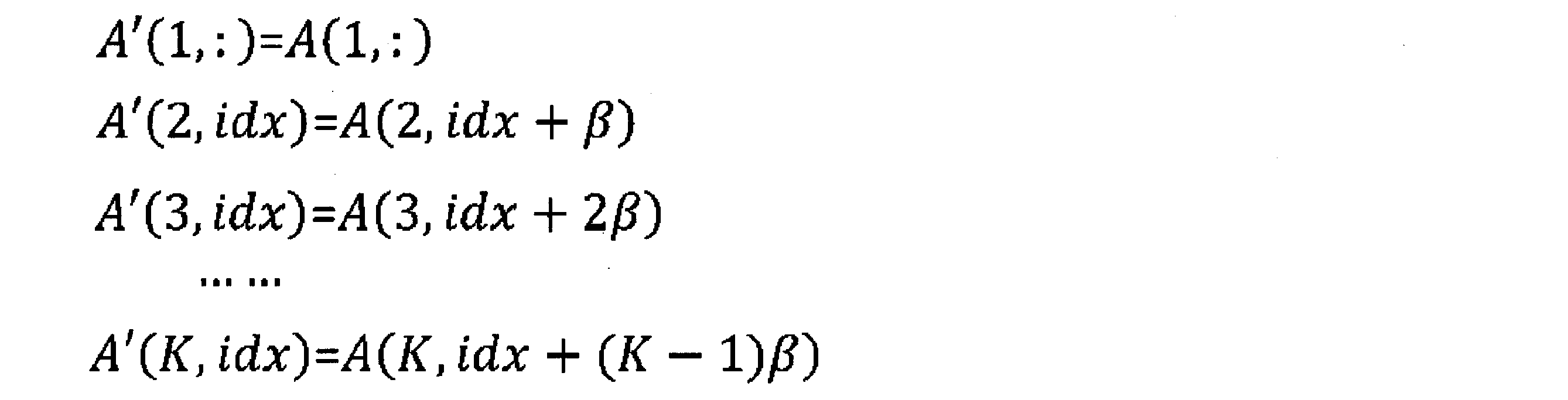
ここで、β=β2である。 FIG. 11A and FIG. 11B are schematic diagrams for explaining the case where the offset value is an integer and the case where it is a decimal. The unit of the offset values β 1 ,..., Β K is an index, not a constant. For example, β 3 = 2β 2 . FIG. 11A shows a case where the offset value β 2 corresponding to thecandidate prediction direction 156 is an integer, for example, 1. The pixel value of the new reference line A new at the horizontal index idx is equal to the pixel value of the pixel 150 at the index idx of the first / nearest neighbor line 314 (A (1, :)) and the second line 316 (A ( 2, :)) includes a weighted linear sum of the pixel value of the pixel 152 at the index idx + β 2 and the pixel value of the pixel 154 at the index idx + 2β 2 of the third line 318 (A (3, :)). A line A ′ (k, :) obtained by offsetting the k-th line A (k, :) as shown in FIG. 11A is expressed as follows.
Here is a β = β 2.
ここで、β=β2である。 FIG. 11A and FIG. 11B are schematic diagrams for explaining the case where the offset value is an integer and the case where it is a decimal. The unit of the offset values β 1 ,..., Β K is an index, not a constant. For example, β 3 = 2β 2 . FIG. 11A shows a case where the offset value β 2 corresponding to the
Here is a β = β 2.
オフセット値が小数の場合は2つの隣り合う画素の画素値の内挿が用いられる。図11Bは候補予測方向158に応じたオフセット値β2が小数である場合を示す。第kラインA(k,:)を図11Bに示される通りにオフセットして得られるラインA’(k,:)は以下の様に表される。
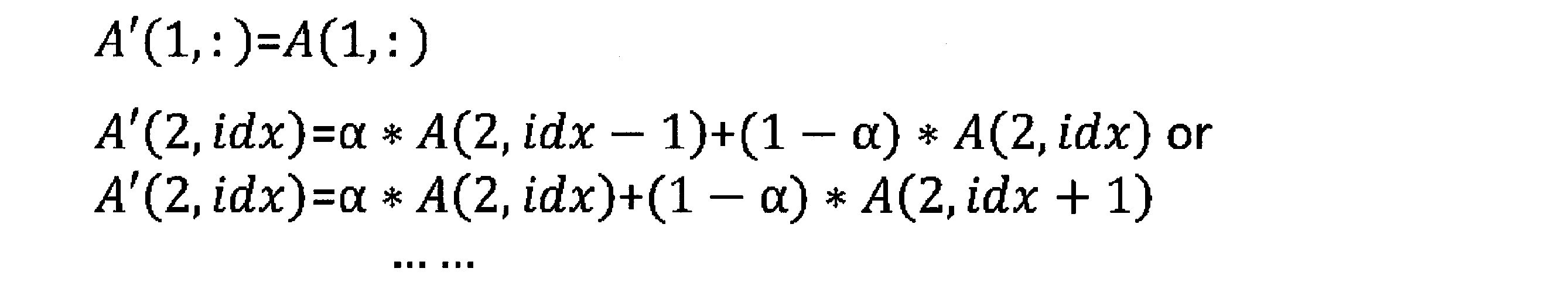
A’(2,idx)を表す式として上段のものを用いるか下段のものを用いるかは、候補予測方向の角度による。αはA’(k,idx)とA(k,idx)とが重なり合う部分の比率である。 When the offset value is decimal, interpolation of pixel values of two adjacent pixels is used. Figure 11B shows the case where the offset value beta 2 corresponding to thecandidate prediction direction 158 is decimal. A line A ′ (k, :) obtained by offsetting the kth line A (k, :) as shown in FIG. 11B is expressed as follows.
Whether the upper one or the lower one is used as an expression representing A ′ (2, idx) depends on the angle of the candidate prediction direction. α is a ratio of a portion where A ′ (k, idx) and A (k, idx) overlap.
A’(2,idx)を表す式として上段のものを用いるか下段のものを用いるかは、候補予測方向の角度による。αはA’(k,idx)とA(k,idx)とが重なり合う部分の比率である。 When the offset value is decimal, interpolation of pixel values of two adjacent pixels is used. Figure 11B shows the case where the offset value beta 2 corresponding to the
Whether the upper one or the lower one is used as an expression representing A ′ (2, idx) depends on the angle of the candidate prediction direction. α is a ratio of a portion where A ′ (k, idx) and A (k, idx) overlap.
図9に戻り、フルチェック部706は、算出されたオフセット値β1、…、βKによりそれぞれオフセットされたK本のラインを合成することにより、新たな参照ラインAnewを生成する(S920)。オフセットされたK本のラインの合成は例えば以下の式2で定義されるK本のラインの線形結合であってもよい。
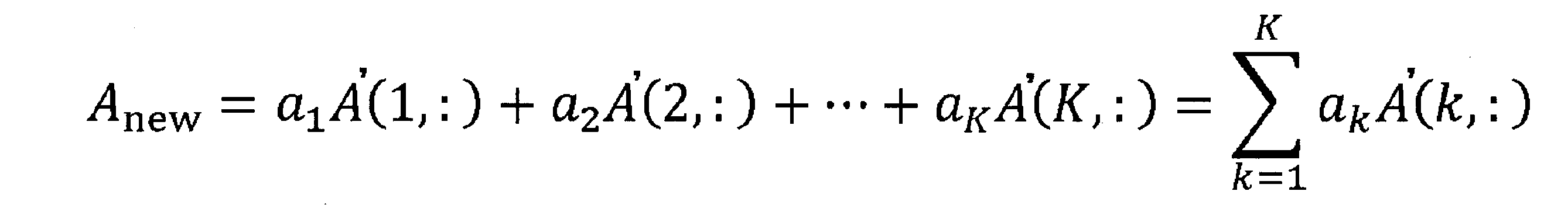
…(式2) Returning to FIG. 9, thefull check unit 706 generates a new reference line A new by synthesizing K lines each offset by the calculated offset values β 1 ,..., Β K (S920). . The composition of the offset K lines may be, for example, a linear combination of K lines defined by Equation 2 below.
... (Formula 2)
…(式2) Returning to FIG. 9, the
... (Formula 2)
フルチェック部706は、ステップS912で選択された候補予測方向について、ステップS920で生成された新たな参照ラインを用いてR-Dコストを算出する(S922)。まだフルチェックされていない候補予測方向がある場合(S924のN)、処理はステップS912に戻る。全ての候補予測方向がフルチェックされた場合(S924のY)、モード決定部708はR-Dコストが最小となる候補予測方向と最近接ライン/生成ラインの別との組を特定する(S926)。予測値生成部710は、特定された参照ライン(最近接ラインまたは新たに生成される参照ライン)と予測方向とに基づいて、処理対象ブロックの画素の予測値を生成し、出力する(S928)。予測値生成部710は、ステップS926における決定の結果を示すサイド情報を生成し、エントロピー符号化部に出力する(S928)。
The full check unit 706 calculates an RD cost for the candidate prediction direction selected in step S912 using the new reference line generated in step S920 (S922). If there is a candidate prediction direction that has not been fully checked yet (N in S924), the process returns to step S912. When all candidate prediction directions are fully checked (Y in S924), the mode determination unit 708 specifies a pair of the candidate prediction direction and the nearest line / generated line that minimizes the RD cost (S926). ). The predicted value generation unit 710 generates and outputs a predicted value of the pixel of the processing target block based on the identified reference line (nearest line or newly generated reference line) and the prediction direction (S928). . The predicted value generation unit 710 generates side information indicating the result of the determination in step S926 and outputs the side information to the entropy encoding unit (S928).
本実施の形態に係る動画像復号装置の構成は、イントラ予測部を除いて図5に示される動画像復号装置102の構成に準じる。本実施の形態に係る復号側のイントラ予測部における処理の流れと図6に示される処理の流れとの主な差異は、本実施の形態では参照フラグが「0」の場合に最近接ラインを参照ラインとすること、新たな参照ラインを生成する際に合成元の各ラインを予測方向に応じてオフセットさせること、である。
The configuration of the video decoding device according to the present embodiment conforms to the configuration of the video decoding device 102 shown in FIG. 5 except for the intra prediction unit. The main difference between the process flow in the decoding-side intra prediction unit according to the present embodiment and the process flow shown in FIG. 6 is that the closest line is set when the reference flag is “0” in the present embodiment. Making a reference line means offsetting each line of the composition source in accordance with the prediction direction when a new reference line is generated.
図12は、第2の実施の形態に係る復号側のイントラ予測部における一連の処理の流れを示すフローチャートである。ステップS650で取得された参照フラグの値が「1」である場合(S652の「1」)、イントラ予測部は図9のステップS916、S918、S920と同様に複数のラインを選択し(S670)、ステップS650で取得されたイントラ予測モードが示す予測方向に基づいて各ラインのオフセット値を算出し(S672)、オフセットされた複数のラインから新たな参照ラインを生成する(S674)。イントラ予測部は、生成された新たな参照ラインと、予測方向と、に基づいて、処理対象ブロックの画素の予測値を生成し、出力する(S676)。
FIG. 12 is a flowchart showing a flow of a series of processes in the decoding-side intra prediction unit according to the second embodiment. When the value of the reference flag acquired in step S650 is “1” (“1” in S652), the intra prediction unit selects a plurality of lines as in steps S916, S918, and S920 in FIG. 9 (S670). Then, an offset value of each line is calculated based on the prediction direction indicated by the intra prediction mode acquired in step S650 (S672), and a new reference line is generated from the offset lines (S674). The intra prediction unit generates and outputs a predicted value of the pixel of the processing target block based on the generated new reference line and the prediction direction (S676).
ステップS652において取得された参照フラグの値が「0」である場合(S652の「0」)、イントラ予測部は処理対象ブロックの周りの再構成済みブロックの最近接ラインを参照ラインとする(S678)。イントラ予測部は最近接ラインと予測方向とに基づいて、処理対象ブロックの画素の予測値を生成し、出力する(S676)。ステップS652での判定結果によって新たな参照ラインが生成されるか、または最近接ラインが参照ラインとして用いられるかが決まる。このため、ステップS652では、イントラ予測で用いられる参照ラインを複数のラインから生成するか否かが決定されるといえる。
When the value of the reference flag acquired in step S652 is “0” (“0” in S652), the intra prediction unit sets the closest line of the reconstructed block around the processing target block as the reference line (S678). ). The intra prediction unit generates and outputs a prediction value of the pixel of the processing target block based on the closest line and the prediction direction (S676). The determination result in step S652 determines whether a new reference line is generated or the closest line is used as a reference line. For this reason, it can be said in step S652 whether or not to generate a reference line used in intra prediction from a plurality of lines.
本実施の形態に係る動画像符号化装置、動画像復号装置によると、第1の実施の形態によって奏される作用効果と同様の作用効果が奏される。加えて、予測方向に合わせて合成元のラインをオフセットさせるので、合成により得られる新たな参照ラインを用いたイントラ予測はより正確な予測値を生成することができる。
According to the moving picture coding apparatus and moving picture decoding apparatus according to the present embodiment, the same operational effects as the operational effects achieved by the first embodiment are achieved. In addition, since the synthesis source line is offset in accordance with the prediction direction, intra prediction using a new reference line obtained by synthesis can generate a more accurate prediction value.
本実施の形態では、粗チェックの際に最近接ラインを用いる場合を説明したが、これに限られず、粗チェックのために、オフセットされた複数のラインから新たな参照ラインを生成してもよい。
In the present embodiment, the case where the closest line is used in the coarse check has been described. However, the present invention is not limited to this, and a new reference line may be generated from a plurality of offset lines for the coarse check. .
本実施の形態では、新たな参照ラインを生成しない場合は最近接ラインを参照ラインとする場合を説明したが、これに限られず、最近接ライン以外の所定のライン、例えば第2ラインや第3ラインを参照ラインとしてもよい。
In the present embodiment, the case where the closest reference line is used as the reference line when a new reference line is not generated has been described. However, the present invention is not limited to this, and a predetermined line other than the closest line, for example, the second line or the third line is used. The line may be a reference line.
(第3の実施の形態)
第1および第2の実施の形態では、a1、…、aKの値は予め決定され、符号化側、復号側それぞれのイントラ予測部に予め与えられる場合を説明した。第3の実施の形態では、この係数a1、…、aKを適応的に決定する。 (Third embodiment)
In the first and second embodiments, the case has been described in which the values of a 1 ,..., A K are determined in advance and given in advance to the intra prediction units on the encoding side and the decoding side, respectively. In the third embodiment, the coefficients a 1 ,..., A K are adaptively determined.
図13は、適応的な線形結合の係数の決定を説明するための模式図である。符号化側のイントラ予測部は、所与の予測方向502に沿って処理対象ブロック504の画素の画素値を足し合わせて平均をとることで、理想的な参照ライン506を生成する。次に、イントラ予測部は、処理対象ブロックの周りの符号化済みブロックの第1ラインA(1,:)、第2ラインA(2,:)、第3ラインA(3,:)の線形結合と理想的な参照ライン506との差が小さくなるように、各ラインに掛け合わせる係数x1、x2、x3を決定する。例えば、係数x1、x2、x3は最小二乗法により決定されてもよい。
FIG. 13 is a schematic diagram for explaining the determination of adaptive linear combination coefficients. The intra prediction unit on the coding side generates an ideal reference line 506 by adding the pixel values of the pixels of the processing target block 504 along a given prediction direction 502 and taking the average. Next, the intra prediction unit linearizes the first line A (1, :), the second line A (2, :), and the third line A (3, :) of the encoded block around the processing target block. The coefficients x 1 , x 2 , and x 3 to be multiplied with each line are determined so that the difference between the combination and the ideal reference line 506 is reduced. For example, the coefficients x 1 , x 2 , x 3 may be determined by a least square method.
本実施の形態に係る動画像符号化装置の構成は、イントラ予測部を除いて図2に示される動画像符号化装置110の構成に準じる。図14は、第3の実施の形態に係る符号化側のイントラ予測部における一連の処理の流れを示すフローチャートである。イントラ予測部は、予測方向を選択する(S450)。イントラ予測部は例えば第2の実施の形態で説明した粗チェックを用いて予測方向を選択してもよい。イントラ予測部は、選択された予測方向における理想的な参照ラインを、処理対象ブロックの実際の画素値から算出する(S452)。イントラ予測部は、利用可能な符号化済みブロックから複数のラインを選択する(S454)。イントラ予測部は、最小二乗法により線形結合の係数を決定する(S456)。図13の例では、係数ベクトルX=(x1、x2、x3)は、bを理想的な参照ライン、Aを選択された複数のラインA(1,:)、A(2,:)、A(3,:)からなる行列とするとき、以下の式3で表される。

…(式3) The configuration of the moving image encoding device according to the present embodiment conforms to the configuration of the movingimage encoding device 110 shown in FIG. 2 except for the intra prediction unit. FIG. 14 is a flowchart showing a flow of a series of processes in the intra prediction unit on the encoding side according to the third embodiment. The intra prediction unit selects a prediction direction (S450). For example, the intra prediction unit may select the prediction direction using the coarse check described in the second embodiment. The intra prediction unit calculates an ideal reference line in the selected prediction direction from the actual pixel value of the processing target block (S452). The intra prediction unit selects a plurality of lines from the available encoded blocks (S454). The intra prediction unit determines a coefficient of linear combination by a least square method (S456). In the example of FIG. 13, the coefficient vector X = (x 1 , x 2 , x 3 ) has b as an ideal reference line and A as a plurality of selected lines A (1, :), A (2 ,: ), A (3, :), it is expressed by the following formula 3.
... (Formula 3)
…(式3) The configuration of the moving image encoding device according to the present embodiment conforms to the configuration of the moving
... (Formula 3)
イントラ予測部は、決定された係数(x1、x2、x3)に基づいて生成された新たな参照ラインと予測方向とに基づいて、処理対象ブロックの画素の予測値を生成し、出力する(S458)。イントラ予測部は、参照フラグ=「1」および予測モード=「決定された予測方向に対応するイントラ予測モード」および決定された係数(x1、x2、x3)を含むサイド情報を生成し、エントロピー符号化部に出力する(S460)。
The intra prediction unit generates a prediction value of the pixel of the processing target block based on the new reference line and the prediction direction generated based on the determined coefficients (x 1 , x 2 , x 3 ), and outputs the prediction value (S458). The intra prediction unit generates side information including reference flag = “1” and prediction mode = “intra prediction mode corresponding to the determined prediction direction” and the determined coefficients (x 1 , x 2 , x 3 ). And output to the entropy encoding unit (S460).
第3の実施の形態に係る動画像復号装置の構成は、第1または第2の実施の形態に係る動画像復号装置の構成に準じる。
The configuration of the video decoding device according to the third embodiment conforms to the configuration of the video decoding device according to the first or second embodiment.
本実施の形態に係る動画像符号化装置、動画像復号装置によると、第1の実施の形態によって奏される作用効果と同様の作用効果が奏される。加えて、複数のラインから生成される参照ラインは理想的な参照ラインに近いので、合成により得られる新たな参照ラインを用いたイントラ予測はより正確な予測値を生成することができる。
According to the moving picture coding apparatus and moving picture decoding apparatus according to the present embodiment, the same operational effects as the operational effects achieved by the first embodiment are achieved. In addition, since a reference line generated from a plurality of lines is close to an ideal reference line, intra prediction using a new reference line obtained by synthesis can generate a more accurate prediction value.
本実施の形態では、サイド情報に係数を入れる分、符号量が増えるが、その係数は理想的な参照ラインに近い合成参照ラインを与えるので、予測残差信号の符号量は減る。したがって、予測残差信号の符号量低減効果が勝っていれば、全体の符号量を低減できる。
In the present embodiment, the amount of code increases by adding a coefficient to the side information, but since the coefficient gives a synthesized reference line close to an ideal reference line, the code amount of the prediction residual signal decreases. Therefore, if the effect of reducing the code amount of the prediction residual signal is superior, the overall code amount can be reduced.
以上、実施の形態の構成と動作について説明した。これらの実施の形態は例示であり、各構成要素や各処理の組み合わせにいろいろな変形例が可能なこと、またそうした変形例も本発明の範囲にあることは当業者に理解される。
The configuration and operation of the embodiment have been described above. It is understood by those skilled in the art that these embodiments are exemplifications, and various modifications are possible for each component and combination of processes, and such modifications are also within the scope of the present invention.
本発明によれば、イントラ予測の確度を高めつつ、それによる処理の負荷の増大を抑えることができる。
According to the present invention, while increasing the accuracy of intra prediction, it is possible to suppress an increase in processing load.
100 配信システム、 102 動画像復号装置、 104 表示装置、 106 ネットワーク、 110 動画像符号化装置
100 distribution system, 102 video decoding device, 104 display device, 106 network, 110 video encoding device
Claims (13)
- イントラ予測を用いて符号化されたブロックを含む動画像を表すビットストリームを復号する復号手段と、
前記復号の結果得られる前記ブロックのレベル値を逆量子化および逆変換して前記ブロックの画素の差分値を生成する逆処理手段と、
前記ブロックの周りの再構成済みブロックの画素値に基づくイントラ予測により前記ブロックの画素の予測値を生成するイントラ予測手段と、
生成された前記差分値および生成された前記予測値に基づいて前記ブロックを再構成する再構成手段と、を備え、
前記イントラ予測手段は、前記ブロックの周りの前記再構成済みブロックの複数のラインを合成することにより、前記イントラ予測で用いられる参照ラインを生成する動画像復号装置。 Decoding means for decoding a bitstream representing a moving image including a block encoded using intra prediction;
Inverse processing means for dequantizing and inversely transforming the level value of the block obtained as a result of the decoding to generate a pixel difference value of the block;
Intra prediction means for generating predicted values of pixels of the block by intra prediction based on pixel values of reconstructed blocks around the block;
Reconstructing means for reconstructing the block based on the generated difference value and the generated predicted value;
The intra prediction unit is a moving picture decoding apparatus that generates a reference line used in the intra prediction by combining a plurality of lines of the reconstructed block around the block. - 前記ビットストリームの前記復号の結果得られる前記ブロックについての識別子に基づいて前記参照ラインを生成するか否かを決定する決定手段をさらに備え、
前記イントラ予測手段は、前記決定手段において前記参照ラインを生成すると決定された場合、前記参照ラインを生成する請求項1に記載の動画像復号装置。 Determining means for determining whether to generate the reference line based on an identifier for the block obtained as a result of the decoding of the bitstream;
The video decoding device according to claim 1, wherein the intra prediction unit generates the reference line when the determination unit determines to generate the reference line. - 前記イントラ予測手段は、前記決定手段において前記参照ラインを生成しないと決定された場合、前記ブロックの周りの前記再構成済みブロックの所定のラインを前記参照ラインに決定する請求項2に記載の動画像復号装置。 The moving image according to claim 2, wherein the intra prediction unit determines a predetermined line of the reconstructed block around the block as the reference line when the determination unit determines not to generate the reference line. Image decoding device.
- 前記複数のラインは前記所定のラインを含む請求項3に記載の動画像復号装置。 The video decoding device according to claim 3, wherein the plurality of lines include the predetermined line.
- 前記複数のラインの合成は前記複数のラインの線形結合である請求項1から4のいずれか1項に記載の動画像復号装置。 The video decoding device according to any one of claims 1 to 4, wherein the synthesis of the plurality of lines is a linear combination of the plurality of lines.
- 前記イントラ予測手段が前記複数のラインを合成する際、前記複数のラインのそれぞれはそのラインが延びる方向に沿って前記イントラ予測における予測方向に応じた量だけオフセットされる請求項1から5のいずれか1項に記載の動画像復号装置。 6. The method according to claim 1, wherein when the intra prediction unit combines the plurality of lines, each of the plurality of lines is offset by an amount corresponding to a prediction direction in the intra prediction along a direction in which the lines extend. The moving image decoding apparatus according to claim 1.
- 前記イントラ予測手段が前記複数のラインを合成する際の規則は、前記ブロックの符号化において、予測方向と画素値とから得られる理想参照ラインと前記複数のラインを合成することにより生成される前記参照ラインとの差が小さくなるよう決定される請求項1から6のいずれか1項に記載の動画像復号装置。 The rule for combining the plurality of lines by the intra prediction unit is generated by combining the plurality of lines with an ideal reference line obtained from a prediction direction and a pixel value in the encoding of the block. The moving picture decoding apparatus according to claim 1, wherein the moving picture decoding apparatus is determined so as to reduce a difference from the reference line.
- イントラ予測を用いて符号化されたブロックを含む動画像を表すビットストリームを復号する復号ステップと、
前記復号の結果得られる前記ブロックのレベル値を逆量子化および逆変換して前記ブロックの画素の差分値を生成する逆処理ステップと、
前記ブロックの周りの再構成済みブロックの画素値に基づくイントラ予測により前記ブロックの画素の予測値を生成するイントラ予測ステップと、
生成された前記差分値および生成された前記予測値に基づいて前記ブロックを再構成する再構成ステップと、を含み、
前記イントラ予測ステップは、前記ブロックの周りの前記再構成済みブロックの複数のラインを合成することにより、前記イントラ予測で用いられる参照ラインを生成するステップを含む動画像復号方法。 A decoding step of decoding a bitstream representing a moving image including a block encoded using intra prediction;
An inverse processing step of dequantizing and inversely transforming the level value of the block obtained as a result of the decoding to generate a pixel difference value of the block;
An intra prediction step of generating a predicted value of a pixel of the block by intra prediction based on a pixel value of a reconstructed block around the block;
Reconstructing the block based on the generated difference value and the generated predicted value, and
The intra prediction step includes a step of generating a reference line used in the intra prediction by combining a plurality of lines of the reconfigured block around the block. - 動画像のブロックの周りの符号化済みブロックの画素値に基づくイントラ予測により前記ブロックの画素の予測値を生成するイントラ予測手段と、
生成された前記予測値に基づいて前記ブロックの画素の差分値を生成する差分生成手段と、
生成された前記差分値を変換および量子化し、レベル値を生成する処理手段と、
生成されたレベル値を符号化してビットストリームを生成する符号化手段と、を備え、
前記イントラ予測手段は、前記ブロックの周りの符号化済みブロックの複数のラインを合成することにより、前記イントラ予測で用いられる参照ラインを生成する動画像符号化装置。 Intra prediction means for generating a prediction value of a pixel of the block by intra prediction based on a pixel value of an encoded block around a block of the moving image;
Difference generation means for generating a difference value of pixels of the block based on the generated predicted value;
Processing means for converting and quantizing the generated difference value to generate a level value;
Encoding means for encoding the generated level value to generate a bitstream,
The said intra prediction means is a moving image encoder which produces | generates the reference line used by the said intra prediction by synthesize | combining the several line of the encoded block around the said block. - 前記イントラ予測手段において前記参照ラインを生成するか否かを決定する決定手段をさらに備え、
前記符号化手段によって生成される前記ビットストリームは前記決定手段における決定の結果を示す識別子を含む請求項9に記載の動画像符号化装置。 A decision means for deciding whether or not to generate the reference line in the intra prediction means;
The moving picture encoding apparatus according to claim 9, wherein the bit stream generated by the encoding unit includes an identifier indicating a result of determination by the determination unit. - 前記イントラ予測手段が前記複数のラインを合成する際の規則は、予測方向と画素値とから得られる理想参照ラインと前記複数のラインを合成することにより生成される前記参照ラインとの差が小さくなるよう決定される請求項9または10に記載の動画像符号化装置。 The rule when the intra prediction unit combines the plurality of lines is such that a difference between an ideal reference line obtained from a prediction direction and a pixel value and the reference line generated by combining the plurality of lines is small. The moving picture coding apparatus according to claim 9 or 10, wherein the moving picture coding apparatus is determined to be.
- 動画像のブロックの周りの符号化済みブロックの画素値に基づくイントラ予測により前記ブロックの画素の予測値を生成するイントラ予測ステップと、
生成された前記予測値と対応する画素値とに基づいて前記ブロックの画素の差分値を生成する差分生成ステップと、
生成された前記差分値を変換および量子化し、レベル値を生成する処理ステップと、
生成されたレベル値を符号化してビットストリームを生成する符号化ステップと、を含み、
前記イントラ予測ステップは、前記ブロックの周りの符号化済みブロックの複数のラインを合成することにより、前記イントラ予測で用いられる参照ラインを生成するステップを含む動画像符号化方法。 An intra prediction step of generating a prediction value of a pixel of the block by intra prediction based on a pixel value of an encoded block around the block of the moving image;
A difference generation step of generating a difference value of pixels of the block based on the generated predicted value and a corresponding pixel value;
Processing and transforming and quantizing the generated difference value to generate a level value;
Encoding a generated level value to generate a bitstream; and
The intra prediction step includes a step of generating a reference line used in the intra prediction by synthesizing a plurality of lines of encoded blocks around the block. - 請求項1から7のいずれか1項に記載の前記動画像復号装置または請求項9から11のいずれか1項に記載の前記動画像符号化装置としてコンピュータを機能させるプログラムを有することを特徴とするコンピュータ可読記録媒体。 A program for causing a computer to function as the moving picture decoding apparatus according to any one of claims 1 to 7 or the moving picture encoding apparatus according to any one of claims 9 to 11 is provided. A computer-readable recording medium.
Priority Applications (3)
| Application Number | Priority Date | Filing Date | Title |
|---|---|---|---|
| EP17852691.9A EP3518545A4 (en) | 2016-09-21 | 2017-07-28 | Moving-image decoder, moving-image decoding method, moving-image encoder, moving-image encoding method, and computer readable recording medium |
| US16/329,601 US11451771B2 (en) | 2016-09-21 | 2017-07-28 | Moving-image decoder using intra-prediction, moving-image decoding method using intra-prediction, moving-image encoder using intra-prediction, moving-image encoding method using intra-prediction, and computer readable recording medium |
| CN201780051864.8A CN109644278B (en) | 2016-09-21 | 2017-07-28 | Video decoding device, video decoding method, video encoding device, video encoding method, and computer-readable storage medium |
Applications Claiming Priority (2)
| Application Number | Priority Date | Filing Date | Title |
|---|---|---|---|
| JP2016-184653 | 2016-09-21 | ||
| JP2016184653A JP6669622B2 (en) | 2016-09-21 | 2016-09-21 | Moving image decoding device, moving image decoding method, moving image encoding device, moving image encoding method, and computer-readable recording medium |
Publications (1)
| Publication Number | Publication Date |
|---|---|
| WO2018055910A1 true WO2018055910A1 (en) | 2018-03-29 |
Family
ID=61689441
Family Applications (1)
| Application Number | Title | Priority Date | Filing Date |
|---|---|---|---|
| PCT/JP2017/027459 WO2018055910A1 (en) | 2016-09-21 | 2017-07-28 | Moving-image decoder, moving-image decoding method, moving-image encoder, moving-image encoding method, and computer readable recording medium |
Country Status (5)
| Country | Link |
|---|---|
| US (1) | US11451771B2 (en) |
| EP (1) | EP3518545A4 (en) |
| JP (1) | JP6669622B2 (en) |
| CN (1) | CN109644278B (en) |
| WO (1) | WO2018055910A1 (en) |
Families Citing this family (4)
| Publication number | Priority date | Publication date | Assignee | Title |
|---|---|---|---|---|
| US10931963B2 (en) * | 2017-12-07 | 2021-02-23 | Tencent America LLC | Method and apparatus for video coding |
| AU2019292266B2 (en) | 2018-06-25 | 2023-02-09 | Guangdong Oppo Mobile Telecommunications Corp., Ltd. | Intra-frame prediction method and device |
| JP7084808B2 (en) * | 2018-07-12 | 2022-06-15 | 日本放送協会 | Encoding device, decoding device, and program |
| CN111757105B (en) * | 2020-06-30 | 2023-07-04 | 北京百度网讯科技有限公司 | Image coding processing method, device, equipment and medium |
Citations (3)
| Publication number | Priority date | Publication date | Assignee | Title |
|---|---|---|---|---|
| JP2007300380A (en) * | 2006-04-28 | 2007-11-15 | Ntt Docomo Inc | Image predictive encoding device, image predictive encoding method, image predictive encoding program, image predictive decoding device, image predictive decoding method, and image predictive decoding program |
| JP2013141187A (en) * | 2012-01-06 | 2013-07-18 | Sony Corp | Image processing apparatus and image processing method |
| US20160073107A1 (en) * | 2013-04-15 | 2016-03-10 | Intellectual Discovery Co., Ltd | Method and apparatus for video encoding/decoding using intra prediction |
Family Cites Families (31)
| Publication number | Priority date | Publication date | Assignee | Title |
|---|---|---|---|---|
| PL175445B1 (en) * | 1993-11-08 | 1998-12-31 | Sony Corp | Method of encoding moving images, method of decoding moving images, moving image recording medium and moving image encoding apparatus |
| JP4474288B2 (en) * | 2003-01-10 | 2010-06-02 | トムソン ライセンシング | Defining an interpolation filter for error concealment in coded images |
| US20070121728A1 (en) * | 2005-05-12 | 2007-05-31 | Kylintv, Inc. | Codec for IPTV |
| KR100750128B1 (en) * | 2005-09-06 | 2007-08-21 | 삼성전자주식회사 | Method and apparatus for intra prediction of video |
| KR100727972B1 (en) * | 2005-09-06 | 2007-06-14 | 삼성전자주식회사 | Method and apparatus for intra prediction of video |
| KR100745765B1 (en) * | 2006-04-13 | 2007-08-02 | 삼성전자주식회사 | Apparatus and method for intra prediction of an image data, apparatus and method for encoding of an image data, apparatus and method for intra prediction compensation of an image data, apparatus and method for decoding of an image data |
| CN103747263B (en) * | 2006-04-28 | 2017-03-01 | 株式会社Ntt都科摩 | Image prediction encoding device and method and image prediction/decoding device and method |
| KR101103699B1 (en) * | 2007-02-23 | 2012-01-11 | 니폰덴신뎅와 가부시키가이샤 | Video coding method and decoding method, their device, their program and program-recorded medium |
| JP2008271371A (en) * | 2007-04-24 | 2008-11-06 | Sharp Corp | Moving image encoding apparatus, moving image decoding apparatus, moving image encoding method, moving image decoding method, and program |
| BRPI0817888A2 (en) * | 2007-10-15 | 2015-03-31 | Mitsubishi Electric Corp | Image coding and decoding devices and methods. |
| KR101510108B1 (en) * | 2009-08-17 | 2015-04-10 | 삼성전자주식회사 | Method and apparatus for encoding video, and method and apparatus for decoding video |
| KR101503269B1 (en) * | 2010-04-05 | 2015-03-17 | 삼성전자주식회사 | Method and apparatus for determining intra prediction mode of image coding unit, and method and apparatus for determining intra predion mode of image decoding unit |
| US20120106640A1 (en) * | 2010-10-31 | 2012-05-03 | Broadcom Corporation | Decoding side intra-prediction derivation for video coding |
| EP2666295A1 (en) * | 2011-01-21 | 2013-11-27 | Thomson Licensing | Methods and apparatus for geometric-based intra prediction |
| US20120300844A1 (en) * | 2011-05-26 | 2012-11-29 | Sharp Laboratories Of America, Inc. | Cascaded motion compensation |
| US20120300838A1 (en) * | 2011-05-26 | 2012-11-29 | Sharp Laboratories Of America, Inc. | Low resolution intra prediction |
| TWI602421B (en) * | 2011-06-13 | 2017-10-11 | Sun Patent Trust | Image decoding method and image decoding apparatus |
| US10306222B2 (en) * | 2011-06-20 | 2019-05-28 | Hfi Innovation Inc. | Method and apparatus of directional intra prediction |
| CN103650496B (en) * | 2011-07-12 | 2018-09-21 | 华为技术有限公司 | Intra prediction pixel-based for being encoded in HEVC |
| US9699452B2 (en) * | 2011-09-15 | 2017-07-04 | Vid Scale, Inc | Systems and methods for spatial prediction |
| US8948529B1 (en) * | 2012-10-30 | 2015-02-03 | Google Inc. | Multi-pass encoding |
| CA2896637C (en) * | 2013-03-26 | 2018-02-13 | Mediatek Inc. | Method of cross color intra prediction |
| US9503751B2 (en) * | 2013-10-17 | 2016-11-22 | Hfi Innovation Inc. | Method and apparatus for simplified depth coding with extended prediction modes |
| JP6446070B2 (en) * | 2014-07-07 | 2018-12-26 | 寰發股▲ふん▼有限公司HFI Innovation Inc. | Intra-block copy search and coverage method |
| EP3198867A4 (en) * | 2014-10-31 | 2018-04-04 | MediaTek Inc. | Method of improved directional intra prediction for video coding |
| EP3262837A4 (en) * | 2015-02-25 | 2018-02-28 | Telefonaktiebolaget LM Ericsson (publ) | Encoding and decoding of inter pictures in a video |
| JP6671339B2 (en) | 2015-02-27 | 2020-03-25 | Kddi株式会社 | Encoding device and decoding device |
| US10390021B2 (en) * | 2016-03-18 | 2019-08-20 | Mediatek Inc. | Method and apparatus of video coding |
| US10944963B2 (en) * | 2016-05-25 | 2021-03-09 | Arris Enterprises Llc | Coding weighted angular prediction for intra coding |
| US10230961B2 (en) * | 2016-06-03 | 2019-03-12 | Mediatek Inc. | Method and apparatus for template-based intra prediction in image and video coding |
| US11368681B2 (en) | 2016-07-18 | 2022-06-21 | Electronics And Telecommunications Research Institute | Image encoding/decoding method and device, and recording medium in which bitstream is stored |
-
2016
- 2016-09-21 JP JP2016184653A patent/JP6669622B2/en active Active
-
2017
- 2017-07-28 EP EP17852691.9A patent/EP3518545A4/en active Pending
- 2017-07-28 CN CN201780051864.8A patent/CN109644278B/en active Active
- 2017-07-28 US US16/329,601 patent/US11451771B2/en active Active
- 2017-07-28 WO PCT/JP2017/027459 patent/WO2018055910A1/en unknown
Patent Citations (3)
| Publication number | Priority date | Publication date | Assignee | Title |
|---|---|---|---|---|
| JP2007300380A (en) * | 2006-04-28 | 2007-11-15 | Ntt Docomo Inc | Image predictive encoding device, image predictive encoding method, image predictive encoding program, image predictive decoding device, image predictive decoding method, and image predictive decoding program |
| JP2013141187A (en) * | 2012-01-06 | 2013-07-18 | Sony Corp | Image processing apparatus and image processing method |
| US20160073107A1 (en) * | 2013-04-15 | 2016-03-10 | Intellectual Discovery Co., Ltd | Method and apparatus for video encoding/decoding using intra prediction |
Non-Patent Citations (2)
| Title |
|---|
| C. W. SEO: "Korea , CE6.a : Bi- Intra Prediction using Slope information", JOINT COLLABORATIVE TEAM ON VIDEO CODING (JCT-VC) OF ITU-T SG16 WP3 AND ISO/IEC JTC1/SC29/WG11 , JCTVC-E170, 16 March 2011 (2011-03-16), Seoul, pages 1 - 4, XP030048255, Retrieved from the Internet <URL:http://phenix.it-sudparis.eu/jct/ doc_end_user/documents/5_Geneva/wg11/JCTVC- E170-v4.zip> * |
| See also references of EP3518545A4 * |
Also Published As
| Publication number | Publication date |
|---|---|
| US20190230374A1 (en) | 2019-07-25 |
| EP3518545A1 (en) | 2019-07-31 |
| JP6669622B2 (en) | 2020-03-18 |
| CN109644278B (en) | 2023-06-27 |
| CN109644278A (en) | 2019-04-16 |
| JP2018050195A (en) | 2018-03-29 |
| US11451771B2 (en) | 2022-09-20 |
| EP3518545A4 (en) | 2020-05-06 |
Similar Documents
| Publication | Publication Date | Title |
|---|---|---|
| KR102046521B1 (en) | Methods of decoding using skip mode and apparatuses for using the same | |
| JP5061179B2 (en) | Illumination change compensation motion prediction encoding and decoding method and apparatus | |
| US9185428B2 (en) | Motion vector scaling for non-uniform motion vector grid | |
| AU2012272779B2 (en) | Method and apparatus for motion compensation prediction | |
| WO2018055910A1 (en) | Moving-image decoder, moving-image decoding method, moving-image encoder, moving-image encoding method, and computer readable recording medium | |
| KR102518627B1 (en) | Image encoding method, decoding method, encoder and decoder | |
| JP4626608B2 (en) | Moving picture hierarchy coding apparatus, moving picture hierarchy coding program, moving picture hierarchy decoding apparatus, and moving picture hierarchy decoding program | |
| US20240031565A1 (en) | Intra-Prediction on Non-dyadic Blocks | |
| JP6539580B2 (en) | Inter prediction apparatus, inter prediction method, moving picture coding apparatus, moving picture decoding apparatus, and computer readable recording medium | |
| JP6865870B2 (en) | Moving image decoding device, moving image decoding method, moving image coding device, moving image coding method and computer-readable recording medium | |
| JP2018107692A (en) | Moving image decoder, moving image decoding method, moving image encoder, moving image encoding method and computer readable recording medium | |
| US20130322535A1 (en) | Method for encoding and decoding images using plurality of reference images and device using method | |
| JP2018032913A (en) | Video encoder, program and method, and video decoder, program and method, and video transmission system | |
| WO2023274372A1 (en) | Method, device, and medium for video processing | |
| WO2023277960A1 (en) | Harmonized design for offset based refinement and multiple reference line selection | |
| CN117356094A (en) | Method, apparatus and medium for video processing | |
| WO2012141500A2 (en) | Image encoding method using a skip mode, and a device using the method | |
| JP2016051922A (en) | Dynamic image encoding device, dynamic image decoding device, dynamic image processing system, dynamic image encoding method, dynamic image decoding method, and program | |
| KR20130050534A (en) | Methods of encoding using hadamard transform and apparatuses using the same |
Legal Events
| Date | Code | Title | Description |
|---|---|---|---|
| 121 | Ep: the epo has been informed by wipo that ep was designated in this application |
Ref document number: 17852691 Country of ref document: EP Kind code of ref document: A1 |
|
| NENP | Non-entry into the national phase |
Ref country code: DE |
|
| ENP | Entry into the national phase |
Ref document number: 2017852691 Country of ref document: EP Effective date: 20190423 |