WO2018047730A1 - Image processing system, image processing method, and computer program - Google Patents
Image processing system, image processing method, and computer program Download PDFInfo
- Publication number
- WO2018047730A1 WO2018047730A1 PCT/JP2017/031537 JP2017031537W WO2018047730A1 WO 2018047730 A1 WO2018047730 A1 WO 2018047730A1 JP 2017031537 W JP2017031537 W JP 2017031537W WO 2018047730 A1 WO2018047730 A1 WO 2018047730A1
- Authority
- WO
- WIPO (PCT)
- Prior art keywords
- image
- individual
- area
- region
- frame
- Prior art date
Links
Images


Classifications
-
- G—PHYSICS
- G09—EDUCATION; CRYPTOGRAPHY; DISPLAY; ADVERTISING; SEALS
- G09G—ARRANGEMENTS OR CIRCUITS FOR CONTROL OF INDICATING DEVICES USING STATIC MEANS TO PRESENT VARIABLE INFORMATION
- G09G5/00—Control arrangements or circuits for visual indicators common to cathode-ray tube indicators and other visual indicators
- G09G5/36—Control arrangements or circuits for visual indicators common to cathode-ray tube indicators and other visual indicators characterised by the display of a graphic pattern, e.g. using an all-points-addressable [APA] memory
- G09G5/37—Details of the operation on graphic patterns
- G09G5/377—Details of the operation on graphic patterns for mixing or overlaying two or more graphic patterns
-
- G—PHYSICS
- G02—OPTICS
- G02B—OPTICAL ELEMENTS, SYSTEMS OR APPARATUS
- G02B27/00—Optical systems or apparatus not provided for by any of the groups G02B1/00 - G02B26/00, G02B30/00
- G02B27/01—Head-up displays
- G02B27/0101—Head-up displays characterised by optical features
-
- G—PHYSICS
- G02—OPTICS
- G02B—OPTICAL ELEMENTS, SYSTEMS OR APPARATUS
- G02B27/00—Optical systems or apparatus not provided for by any of the groups G02B1/00 - G02B26/00, G02B30/00
- G02B27/01—Head-up displays
- G02B27/017—Head mounted
- G02B27/0172—Head mounted characterised by optical features
-
- G—PHYSICS
- G06—COMPUTING; CALCULATING OR COUNTING
- G06F—ELECTRIC DIGITAL DATA PROCESSING
- G06F3/00—Input arrangements for transferring data to be processed into a form capable of being handled by the computer; Output arrangements for transferring data from processing unit to output unit, e.g. interface arrangements
- G06F3/14—Digital output to display device ; Cooperation and interconnection of the display device with other functional units
- G06F3/147—Digital output to display device ; Cooperation and interconnection of the display device with other functional units using display panels
-
- G—PHYSICS
- G06—COMPUTING; CALCULATING OR COUNTING
- G06T—IMAGE DATA PROCESSING OR GENERATION, IN GENERAL
- G06T15/00—3D [Three Dimensional] image rendering
- G06T15/005—General purpose rendering architectures
-
- G—PHYSICS
- G06—COMPUTING; CALCULATING OR COUNTING
- G06T—IMAGE DATA PROCESSING OR GENERATION, IN GENERAL
- G06T7/00—Image analysis
- G06T7/97—Determining parameters from multiple pictures
-
- G—PHYSICS
- G09—EDUCATION; CRYPTOGRAPHY; DISPLAY; ADVERTISING; SEALS
- G09G—ARRANGEMENTS OR CIRCUITS FOR CONTROL OF INDICATING DEVICES USING STATIC MEANS TO PRESENT VARIABLE INFORMATION
- G09G5/00—Control arrangements or circuits for visual indicators common to cathode-ray tube indicators and other visual indicators
- G09G5/14—Display of multiple viewports
-
- G—PHYSICS
- G09—EDUCATION; CRYPTOGRAPHY; DISPLAY; ADVERTISING; SEALS
- G09G—ARRANGEMENTS OR CIRCUITS FOR CONTROL OF INDICATING DEVICES USING STATIC MEANS TO PRESENT VARIABLE INFORMATION
- G09G5/00—Control arrangements or circuits for visual indicators common to cathode-ray tube indicators and other visual indicators
- G09G5/36—Control arrangements or circuits for visual indicators common to cathode-ray tube indicators and other visual indicators characterised by the display of a graphic pattern, e.g. using an all-points-addressable [APA] memory
-
- G—PHYSICS
- G02—OPTICS
- G02B—OPTICAL ELEMENTS, SYSTEMS OR APPARATUS
- G02B27/00—Optical systems or apparatus not provided for by any of the groups G02B1/00 - G02B26/00, G02B30/00
- G02B27/01—Head-up displays
- G02B27/0101—Head-up displays characterised by optical features
- G02B2027/0123—Head-up displays characterised by optical features comprising devices increasing the field of view
-
- G—PHYSICS
- G09—EDUCATION; CRYPTOGRAPHY; DISPLAY; ADVERTISING; SEALS
- G09G—ARRANGEMENTS OR CIRCUITS FOR CONTROL OF INDICATING DEVICES USING STATIC MEANS TO PRESENT VARIABLE INFORMATION
- G09G2340/00—Aspects of display data processing
- G09G2340/10—Mixing of images, i.e. displayed pixel being the result of an operation, e.g. adding, on the corresponding input pixels
-
- G—PHYSICS
- G09—EDUCATION; CRYPTOGRAPHY; DISPLAY; ADVERTISING; SEALS
- G09G—ARRANGEMENTS OR CIRCUITS FOR CONTROL OF INDICATING DEVICES USING STATIC MEANS TO PRESENT VARIABLE INFORMATION
- G09G2370/00—Aspects of data communication
- G09G2370/02—Networking aspects
- G09G2370/022—Centralised management of display operation, e.g. in a server instead of locally
Definitions
- This invention relates to image processing technology.
- a head-mounted display (hereinafter also referred to as “HMD”) is mounted on the user's head and provides the user with a virtual reality (VR) world.
- VR virtual reality
- an application that allows a user to play a game while viewing a screen displayed on the HMD has also appeared.
- a conventional stationary display such as a television
- the user's field of view is widened outside the screen, and the user may not be able to concentrate on the screen or may not be immersed in the game.
- the HMD when the HMD is attached, the user only sees the video displayed on the HMD, so that the sense of immersion in the video world is increased, and the entertainment characteristics of the game are further enhanced.
- the screen on which the video is displayed is divided into a plurality of areas, the images of the plurality of areas are drawn in parallel by a plurality of devices, and the images of the plurality of areas are integrated to display a high-resolution image. Possible configurations are possible.
- the present invention has been made in view of these problems, and a main object thereof is to provide a technique for suppressing a delay in displaying a high-resolution image.
- an image processing system includes a plurality of drawing units that draw a plurality of individual images to be displayed in a plurality of individual regions obtained by dividing a frame display region in parallel with each other.
- An image composition unit that generates a composite image obtained by combining a plurality of individual images drawn by a plurality of drawing units, and a display control unit that displays the composite image on a head-mounted display.
- the image composition unit When an individual image of at least one individual area is delayed at the processing timing of a certain frame, the image composition unit generates a composite image by applying the individual image of the previous frame as the individual image of the individual area.
- Another aspect of the present invention is an image processing method.
- the step of displaying on the head mounted display is executed by one computer, or the plurality of computers are executed in a distributed manner, and the step of generating a composite image includes at least one individual region at a processing timing of a certain frame.
- a synthesized image is generated by applying the individual image of the previous frame as the individual image of the individual region.
- FIG. 5 is a block diagram illustrating a functional configuration of a master node in FIG. 4.
- FIG. 5 is a block diagram illustrating a functional configuration of each of a plurality of drawing nodes in FIG. 4.
- FIG. 5 is a block diagram illustrating a functional configuration of a display control node in FIG. 4. It is a flowchart which shows operation
- the outline of the embodiment will be described before the embodiment is described in detail.
- display of high-resolution images such as 8K and 16K is required.
- Image processing related to communication or generation of high-resolution images is heavy.
- the present inventor divides a screen on which an image is displayed into a plurality of areas, and the plurality of drawing nodes (GPUs) draw the images of the plurality of areas in a distributed manner, and the display nodes integrate the images of the plurality of areas. It was considered that the processing load of high-resolution images can be reduced by displaying the images.
- an image processing method for displaying an image based on the previous frame as an alternative image for an area where the distributed drawing result is delayed among a plurality of areas obtained by dividing the screen in other words, an image of an updatable area
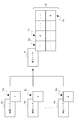
- FIG. 1 shows the principle of the image processing method in the embodiment.
- the screen 10 that is a display area of a frame image is divided into a plurality of individual areas (individual area 12a, individual area 12b, individual area 12c, and individual area 12d).
- the frame image is, for example, an image of individual frames constituting a VR video, and is a single image displayed on the display device at a certain timing.
- the screen 10 can also be said to be an area for rendering a frame image.
- (2) images of a plurality of individual areas are generated in parallel by a plurality of nodes.
- the individual image 14a to be displayed in the individual area 12a, the individual image 14b to be displayed in the individual area 12b, the individual image 14c to be displayed in the individual area 12c, and the individual image 14d to be displayed in the individual area 12d are four nodes.
- the display node generates a frame image 16 to be displayed on the display device by synthesizing the individual images distributed and generated by the plurality of nodes.
- the drawing process of the frame image 16 is executed in a distributed manner and in parallel by a plurality of nodes (GPUs), thereby realizing drawing of a high-resolution image in real time.
- GPUs nodes
- the frame image 16 is generated by using the individual image used for the position of the individual region 12c at the time of generating the previous frame image 16 as an alternative image instead of the original individual image of the individual region 12c.
- the frame image 16 is generated after the arrival of the image of the individual area 12c. That is, the acquisition of the delayed individual image is synchronized with the generation of the frame image 16.
- FIG. 2 also shows the principle of the image processing method in the embodiment.
- the drawing node 20a, the drawing node 20b,..., And the drawing node 20n draw the individual image 22a, the individual image 22b,.
- the display node 24 generates a frame image 26 by combining the individual images 22a, the individual images 22b,..., And the individual images 22n.
- the display node 24 delays the display of the frame image 26 without displaying the image of the previous frame. In other words, the frame image 26 is updated in synchronization with the arrival of the delayed individual image 22b.
- the display node 24 displays the frame image 26 by displaying the image of the previous frame in the area of the delayed individual image. Display without delay. In other words, the display of the frame image 26 is prevented from being delayed.
- This configuration is based on the inventor's knowledge that when the number of divisions of the screen is sufficiently large, the portion far from the center of the screen is hardly noticed by the user even if the display is delayed by several frames. However, the user notices when the delay of the individual image exceeds a certain frame.
- the display node 24 waits for the arrival of the delayed individual image 22a or the individual image 22n (in other words, completion of drawing) and updates the frame image 26. .
- FIG. 3 shows the principle of the image processing method in the modified example.
- the symbols in FIG. 3 correspond to those in FIG.
- the screen may not be divided equally.
- the image may be divided so that the number of pixels in the individual area away from the center of the screen is smaller than the number of pixels in the individual area near the center of the screen (in other words, the size is reduced). Further, the individual area farther from the center of the screen may be divided so that the number of pixels becomes smaller.
- the rendering of the individual images for example, the individual image 22a, the individual image 22b, and the individual image 22n
- the image of the previous frame is displayed in the delayed individual image area. Good. This makes it more difficult for the user to notice that the image drawing has been delayed.
- FIG. 4 shows the configuration of the image processing system of the embodiment.
- the image processing system 30 includes a drawing node 34 a, a drawing node 34 b, a drawing node 34 n, a display control node 36, and a display device 38 that are collectively referred to as a master node 32 and a drawing node 34.
- Each of these devices is connected via a communication network including a LAN, a WAN, the Internet, and the like.
- the display device 38 sequentially displays images of a plurality of frames constituting the video.
- the display device 38 according to the embodiment is a non-transmissive HMD, and displays a VR video (VR image) output from the display control node 36 on the display unit.
- the master node 32, the drawing node 34, and the display control node 36 cooperate with each other to generate a frame image to be displayed on the display device 38.
- FIG. 5 is a block diagram showing a functional configuration of the master node 32 of FIG.
- the master node 32 includes a control unit 40, a storage unit 42, and a communication unit 44.
- the control unit 40 executes various data processing.
- the storage unit 42 is a storage area that stores data that is referred to or updated by the control unit 40.
- the communication unit 44 communicates with an external device according to a predetermined communication protocol.
- the control unit 40 transmits / receives data to / from a plurality of drawing nodes 34 via the communication unit 44.
- the master node 32 may be a data processing device (such as a server) that constitutes a cloud system.
- each block of the control unit 40 may be implemented as a computer program, and the computer program may be installed in the storage of the master node 32.
- the function of each block in the control unit 40 may be exhibited by the CPU of the master node 32 reading the computer program into the main memory and executing it.
- the storage unit 42 may be realized by the main memory or storage of the master node 32. The same applies to the drawing node 34 and the display control node 36 in FIG.
- the storage unit 42 includes a frame data storage unit 46 and an individual area data storage unit 48.
- the frame data storage unit 46 holds data of a plurality of frames constituting a video to be displayed on the display device 38.
- the frame data stored in the frame data storage unit 46 includes data necessary for rendering the frame image. For example, the shape of the object, the viewpoint for capturing the object, the texture of the object surface (information on texture mapping), the light source, the shading Contains information.
- the individual area data storage unit 48 holds data of a plurality of individual areas constituting the screen on which the frame image is displayed.
- the individual area data held in the individual area data storage unit 48 includes data necessary for rendering an individual image that is an image of the individual area. For example, it includes data extracted from frame data, specifically including information on the shape and texture of an object present in each individual area, and further includes information on viewpoints, light sources, and shading.
- the data necessary for rendering held in the frame data storage unit 46 and the individual area data storage unit 48 may be point group data that represents the appearance of the shooting space by a set of a plurality of points.
- the point cloud data may be generated by combining output images of a plurality of cameras taken from different positions and angles in the same space.
- the data of each point in the point group includes three-dimensional coordinate data indicating the position in the imaging space and data indicating the color.
- the three-dimensional coordinate data includes, for example, a coordinate value in the horizontal direction (X-axis direction), a coordinate value in the vertical direction (Y-axis direction), and a coordinate value in the depth direction (Z-axis direction) indicating the absolute position in the imaging space. It may be a combination.
- the data indicating the color may be, for example, an RGBA color model value.
- the control unit 40 includes a screen division unit 50 and an individual area data distribution unit 52.
- the screen dividing unit 50 divides a screen, which is a frame image display area, into a plurality of individual areas.
- the screen dividing unit 50 extracts a plurality of individual region data for rendering images of a plurality of individual regions from the frame data stored in the frame data storage unit 46, and the individual region data of each individual region is converted into individual region data.
- the screen dividing unit 50 of the embodiment equally divides the screen into four individual areas. For example, as shown in FIG. 1, it may be divided into an upper left area, a lower left area, a lower right area, and an upper right area. As a modification, the screen may be divided into a plurality of regions based on other criteria. Resolution, drawing load, human eyes (such as a user wearing an HMD), and 3D drawing hardware performance (GPU processing speed, CPU processing speed, memory size, memory bandwidth) may be used as parameters for screen division.
- the screen may be divided so that the resolution near the center of the screen (the center of the line of sight) is increased, and the resolution of the area away from the center of the screen (the center of the line of sight) is decreased. Further, the screen may be divided so that the drawing loads of a plurality of areas are leveled. Further, the screen is set so that the resolution or drawing load of the individual area assigned to the drawing node 34 having high drawing performance is relatively high, and the resolution or drawing load of the individual area assigned to the drawing node 34 having low drawing performance is relatively low. May be divided.
- the individual area data distribution unit 52 holds the correspondence between the plurality of individual areas and the plurality of drawing nodes 34.
- the individual area data distribution unit 52 transmits the individual area data of each of the plurality of individual areas to the associated drawing node. For example, the correspondence relationship in which the individual area 12a (ie, the upper left area) and the drawing node 34a, the individual area 12b (ie, the lower left area) and the drawing node 34b, and the individual area 12d (ie, the upper right area) and the drawing node 34n in FIG. It may be determined.
- the individual area data distribution unit 52 transmits the individual area data of the individual area 12a to the drawing node 34a, transmits the individual area data of the individual area 12b to the drawing node 34b, and draws the individual area data of the individual area 12d. Transmit to node 34n.
- FIG. 6 is a block diagram showing a functional configuration of each of the plurality of drawing nodes 34 in FIG.
- the control unit 60, the storage unit 62, and the communication unit 64 in FIG. 6 correspond to the control unit 40, the storage unit 42, and the communication unit 44 in FIG.
- the plurality of drawing nodes 34 may correspond to the drawing nodes 20a, 20b,..., And the drawing nodes 20n in FIG. 2 and may be data processing devices (servers or the like) installed in the cloud.
- the storage unit 62 includes an individual area data storage unit 66 and an individual image storage unit 68.
- the individual area data storage unit 66 holds the individual area data distributed to the own device.
- the individual image storage unit 68 holds data of individual images generated by a drawing unit 72 described later.
- the control unit 60 includes an individual area data acquisition unit 70, a drawing unit 72, and an individual image providing unit 74.
- the individual area data acquisition unit 70 acquires the individual area data transmitted from the master node 32 and stores it in the individual area data storage unit 66.
- the drawing unit 72 reads out the individual region data from the individual region data storage unit 66 and executes a known rendering process, thereby generating individual image data that is a bitmap image to be displayed in the individual region.
- the individual image providing unit 74 transmits the individual image data generated by the drawing unit 72 to the display control node 36.
- FIG. 7 is a block diagram showing a functional configuration of the display control node 36 of FIG.
- the control unit 80, the storage unit 82, and the communication unit 84 in FIG. 7 correspond to the control unit 40, the storage unit 42, and the communication unit 44 in FIG.
- the display control node 36 may correspond to the display node 24 in FIG. 2 and may be a stationary game machine or a PC installed in the user's house. Further, the display control node 36 and the display device 38 may be integrally configured, and may be, for example, a smartphone or a portable game machine.
- the storage unit 82 includes an individual image storage unit 86 and a frame image storage unit 88.
- the individual image storage unit 86 holds individual image data provided from a plurality of drawing nodes 34.
- the frame image storage unit 88 holds frame image data generated by an image composition unit 92 described later.
- the control unit 80 includes an individual image acquisition unit 90, an image composition unit 92, and a frame image output unit 94.
- the individual image acquisition unit 90 acquires data of a plurality of individual images transmitted from the plurality of drawing nodes 34 and sequentially stores them in the individual image storage unit 86.
- the image composition unit 92 synthesizes data of a plurality of individual images held in the individual image storage unit 86, generates frame image data to be displayed on the display device 38, and stores the frame image data in the frame image storage unit 88.
- the frame image output unit 94 outputs the frame image held in the frame image storage unit 88 to the display device 38 in synchronization with the frame display timing, and causes the display device 38 to display the frame image.
- the master node 32 can identify the frame ID (information for identifying the display timing of the frame image) and the area ID (the position of the individual area in the screen) for each individual area data distributed to the plurality of drawing nodes 34. Information).
- Each of the drawing nodes 34 includes a frame ID and a region ID in the individual image data provided to the display control node 36.
- the drawing node 34 may generate a frame image by arranging and synthesizing a plurality of individual image data assigned with the same frame ID at a position identified by the region ID.
- the image composition unit 92 detects a predetermined frame processing timing (for example, display timing or drawing timing) by a known method, and generates a frame image in synchronization with the timing.
- a predetermined frame processing timing for example, display timing or drawing timing
- the image composition unit 92 uses the previous frame as the individual image of the individual area.
- the individual image is applied to generate a frame image.
- the image compositing unit 92 applies the individual image of the previous frame to the individual area where the individual image is delayed, while the other individual area without the delay of the individual image has the current frame arrived by the processing timing.
- a frame image is generated by applying an individual image.
- the individual area in which the individual image that should originally arrive from the rendering node 34 is delayed in other words, the individual area that has not received the individual image before the original reception timing is also referred to as a “delay area”.
- the image composition unit 92 uses the individual image of the immediately preceding frame as the individual image of the previous frame. In other words, the image composition unit 92 uses the individual image of the delay area acquired immediately before from the drawing node 34 as the individual image of the delay area. As a result, it is possible to display content that approximates the individual image that should originally be displayed.
- candidate image data in which the appearance of the 3D space to be rendered is drawn (captured) from all directions, the position of the user's viewpoint, the direction of the line of sight, the angle, and the like. May be stored in advance in association with each other.
- the image composition unit 92 may extract the individual images of the delay region from the candidate image data associated with the user's viewpoint position, line-of-sight direction, angle, and the like at that time.
- the image composition unit 92 may generate a delay region individual image by applying a predetermined filter to the individual image of the previous frame.
- the image composition unit 92 obtains an intermediate image between the individual image received earlier as the individual image in that area and the individual image received after the delay, An individual image of the delay area may be generated by interpolation processing.
- the image composition unit 92 applies the individual image of the previous frame as the individual image of the individual region (that is, the delay region) when the unacquired time of the individual image of the individual region is less than the predetermined time.
- the predetermined time may be determined by a time value such as 100 milliseconds, or may be determined by the number of frames such as 5 frames.
- the image composition unit 92 After waiting for the image to arrive from the drawing node 34, the individual image that has arrived in time and the individual image that has arrived with a delay are combined to generate a frame image. That is, the display of the frame image is delayed in synchronization with the delay of the individual image.
- the image composition unit 92 uses the previous frame as an individual image of the individual area.
- a frame image is generated by applying an individual image.
- the image composition unit 92 waits until the individual image of the individual area arrives from the drawing node 34, and arrives with a delay from the individual image that arrived in time.
- a frame image is generated by combining the individual images. That is, the display of the frame image is delayed in synchronization with the delay of the individual image of the region of interest.
- the region of interest in the embodiment is an individual region located near the center of the screen displaying the frame image. For example, it is an area where the individual image 22b of FIG. 2 is displayed.
- the region that does not correspond to the region of interest is an individual region that is separated from the center of the screen (the distance from the center of the screen is a predetermined value or more).
- the region of interest may be an individual region located in the vicinity of the center of the user's line of sight, and the region not corresponding to the region of interest is separated from the center of the user's line of sight (a distance from the center of the line of sight is predetermined).
- the image composition unit 92 may detect the center position of the user's line of sight based on the user's line-of-sight direction and angle detected by a sensor (not shown) of the display device 38 (for example, HMD). In this modification, when the center of the user's line of sight is the edge of the screen, the center of the screen may correspond to a region that does not correspond to the region of interest.
- FIG. 8 is a flowchart illustrating the operation of the image processing system 30 according to the embodiment.
- the master node 32 divides the display screen of the frame image into a plurality of individual areas, and distributes a plurality of individual area data for rendering the images of the plurality of individual areas to the plurality of drawing nodes 34 (S10). .
- the plurality of drawing nodes 34 draw a plurality of individual images in a plurality of individual regions in parallel (S12).
- the display control node 36 combines the plurality of individual images.
- a frame image is generated (S24).
- the master node 32 determines whether or not the delay amount is less than the predetermined time. Then, it is determined whether or not the delay region corresponds to the region of interest. If the delay amount is less than the predetermined time (Y in S16) and the delay region does not correspond to the region of interest (N in S18), the master node 32 displays an individual image (here, “alternative” to be displayed in the delay region). (Referred to as “image”) (S20). Then, a frame image is generated by synthesizing the individual image of the current frame that has reached the drawing timing and the substitute image generated in S20 (S24).
- the display control node 36 displays the individual image (“delayed image” that should be originally displayed in the delay region. ").” Is waited until it arrives from the drawing node 34 (N in S22).
- the display control node 36 When the delay image is received from the rendering node 34 (Y in S22), the display control node 36 generates a frame image obtained by combining the individual image of the current frame that has reached the rendering timing and the delayed image of the current frame. Generate (S24).
- the drawing node 34 outputs the generated frame image to the display device 38, and the display device 38 displays the frame image input from the drawing node 34 (S26).
- the image processing system 30 of the embodiment when a user views a VR video on the HMD, that is, when the number of screen divisions is sufficiently large, the delay of a portion that is not a region of interest is delayed by several frames.
- the image of the previous frame is displayed in an area where drawing is delayed based on the characteristic that it is difficult to notice. Thereby, it is possible to suppress the user from feeling uncomfortable with the delay in drawing.
- the update of the individual image is delayed by a certain frame or more, the user feels uncomfortable by waiting for the update of the individual image delayed so as to synchronize the entire frame image.
- the master node 32 of the above embodiment transmits individual area data for generating an image of an individual area in which each node is associated in advance to each of the plurality of drawing nodes 34.
- the screen on which the frame image is displayed is divided into four, the individual area data corresponding to the upper left area is transmitted to the drawing node 34a, the individual area data corresponding to the lower left area is transmitted to the drawing node 34b, and the upper right area corresponds to The individual area data to be transmitted is transmitted to the drawing node 34n.
- the load may be biased to a specific drawing node. For example, there may occur a situation in which the drawing load greatly exceeds the allowable value at one drawing node, while the drawing load greatly falls below the allowable value at another drawing node. As a result, the drawing process tends to be delayed at a drawing node where the load is concentrated. Therefore, the screen division unit 50 of the master node 32 in the modification dynamically determines the screen division mode so that the load of each drawing node is as even as possible.
- the screen dividing unit 50 may determine the size (in other words, the range) of each individual region so that the load distribution of each drawing node is equal to or less than a predetermined value.
- FIG. 9 schematically shows a method for leveling the loads of a plurality of drawing nodes.
- a drawing node 34c (not shown) exists as the fourth drawing node.
- the screen dividing unit 50 divides the screen on which the frame image is displayed into four.
- the drawing node 34a is responsible for drawing the region 100
- the drawing node 34b is responsible for drawing the region 102
- the drawing node 34c is responsible for drawing the region 104
- the drawing node 34n is responsible for drawing the region 106.
- the numbers in each area in FIG. 9A indicate the load of the drawing process.
- the screen dividing unit 50 may calculate the drawing load of each area by a known method based on the data for drawing each area (corresponding to the individual area data in the embodiment).
- the drawing load of each area may be calculated in advance and held in the frame data storage unit 46.
- the numbers in each area may indicate the ratio of the number of points included in each area.
- the load is concentrated on the drawing node 34a.
- the size of the load allowed in each drawing node (hereinafter referred to as “allowable load”) is set to “5” in advance.
- the screen dividing unit 50 divides the region with the maximum load into two along the long side axis, as shown in FIG. For example, the middle points of the long sides may be connected and divided in half.
- the screen dividing unit 50 again has the maximum load as shown in FIG. 9C. The area is divided into two.
- the adjustment unit calculates the difference between the load in each area and the allowable load.
- FIG. 9D shows the calculation result.
- the screen division unit 50 integrates areas where the difference from the allowable load is a predetermined value (here, “4”) or more with adjacent areas.
- FIG. 9F shows the result of integrating the regions. The screen dividing unit 50 ends the adjustment process when the load distribution of each region becomes a predetermined value (for example, “1.6”) or less.
- the individual area data distribution unit 52 of the master node 32 transmits the data of the drawing target block corresponding to the area 110 to the drawing node 34a, and transmits the data of the drawing target block corresponding to the area 112 to the drawing node 34b.
- the drawing target block data corresponding to the region 114 is transmitted to the drawing node 34c, and the drawing target block data corresponding to the region 116 is transmitted to the drawing node 34n.
- the dispersion of the areas 100 to 106 is “13.5”, while the dispersion of the areas 110 to 116 in FIG. 9F is reduced to “1.5”.
- the load of each drawing node can be leveled, and the load can be concentrated on a specific node, and the drawing can be prevented from being delayed at the specific node.
- a second modification will be described.
- a configuration is proposed in which real-time drawing is realized by reducing the drawing load by increasing the resolution of the peripheral area while increasing the resolution of the central area of the screen during image drawing.
- the drawing of the peripheral region may not be in time for the display timing of the frame image depending on the content to be drawn.
- the delay of the display of the frame image is suppressed by allowing the delay of drawing in the peripheral area.
- the central area of the screen may be a region of interest, and may be the central area of the line of sight.
- FIG. 10 schematically shows a screen divided into a plurality of areas.
- the screen shown in FIG. 5 is divided into a central area 120, a peripheral area 122, a peripheral area 124, a peripheral area 126, and a peripheral area 128.
- the screen dividing unit 50 of the master node 32 of this modification divides the display area of the frame so that the number of pixels in the individual area that does not correspond to the region of interest is smaller than the number of pixels in the individual area that corresponds to the area of interest. That is, the screen dividing unit 50 divides the screen so that the number of pixels in the central region 120 is larger than any of the peripheral region 122, the peripheral region 124, the peripheral region 126, and the peripheral region 128.
- the individual area data distribution unit 52 of the master node 32 transmits the individual area data of the central area 120 to the drawing node 34a, and transmits the individual area data of other peripheral areas to the drawing nodes 34b,. .
- the configuration of the drawing node 34 is the same as in the embodiment.
- the display control node 36 waits for the arrival of the image and generates a frame image.
- the display control node 36 allows a certain time delay, that is, the image drawing is performed. A frame image is generated without delay by applying the image of the previous frame to the delayed region. This suppresses display delay as the entire frame image.
- FIG. 11 shows a configuration of the HMD system 130 of the third modified example.
- the client device 132 corresponds to the display control node 36 of the embodiment, and is, for example, a game machine that executes a VR application.
- the client device 132 generates an image in the VR space (referred to as a “VR” image) and displays it on the HMD 134. It is assumed that the display area of the VR image of this modification is divided into five as in the screen of FIG. In drawing a VR image, a high real-time property is required for drawing a center area 120 (also referred to as a center line of sight) of the screen. Therefore, the client device 132 is responsible for drawing the central region 120.
- the drawing processing of the central area 120 uses the performance of the client device 132 to the upper limit. Specifically, the client device 132 transmits data for drawing the peripheral area 122, the peripheral area 124, the peripheral area 126, and the peripheral area 128 to the drawing server 136a, the drawing server 136b, the drawing server 136c, and the drawing server 136d. To do.
- a plurality of drawing servers correspond to the drawing node 34 of the embodiment, and draw the image of the peripheral area in parallel.
- the client device 132 synthesizes the image of the central region 120 drawn by the own device and the images of the plurality of peripheral regions drawn in parallel by the plurality of drawing servers to generate a frame image.
- the client device 132 outputs the generated frame image to the HMD 134 for display.
- an image drawn by each drawing server is sent to the client device 132 via the communication network, and there is a possibility that a delay may occur.
- the image to be rendered in the rendering server is the image of the peripheral area, a delay of a certain time is allowed as in the embodiment, and the frame of the peripheral area where the rendering is delayed is applied by applying the image of the previous frame.
- Generate images without delay As a result, the latest contents are displayed in the center area 120 where the user's interest is gathered in the frame image, and the display delay of the frame image due to the delay in the drawing of the peripheral area can be suppressed.
- the HMD system 130 may further include a master node 32 as in the image processing system 30 of the embodiment.
- the master node 32 distributes the data for drawing the individual images of the peripheral area to a plurality of drawing servers, and directly transmits the data for drawing the individual images of the central area 120 to the client device 132. These individual images may be generated in the client device 132. For example, this is a mode suitable for streaming distribution of video in real space or VR space.
- the technique of the embodiment can be applied to rendering using point cloud data (point cloud), for example, coordinate data and color data of a plurality of points constituting the photographing space.
- point cloud data for example, coordinate data and color data of a plurality of points constituting the photographing space.
- the screen dividing unit 50 of the master node 32 divides a screen, which is a frame image display area, into a plurality of individual areas.
- the screen dividing unit 50 extracts point cloud data (hereinafter also referred to as “individual point cloud data”) for rendering an image of each individual area from the point cloud data as frame data.
- the screen dividing unit 50 may set data of points to be displayed in each individual area as individual point group data for each individual area based on the coordinates of each point included in the point group.
- the individual area data distribution unit 52 of the master node 32 transmits the individual point cloud data of each individual area to the drawing node 34 that should generate an image of each individual area.
- Each of the plurality of drawing nodes 34 generates an individual image of an individual area in charge of the own node based on the individual point cloud data received from the master node 32.
- the display control node 36 combines the individual images generated in parallel by the plurality of drawing nodes 34 to generate a frame image, and causes the display device 38 to display the frame image.
- the point cloud is not uniformly distributed to the plurality of drawing nodes 34. For this reason, not all drawing nodes 34 can complete drawing processing at the same timing (or by a predetermined timing), and delays in drawing processing of some drawing nodes 34 lead to delays in displaying frame images. End up. Therefore, the display control node 36 allows a delay in drawing an area (hereinafter referred to as “peripheral area”) away from the area of interest (for example, the center of the screen or the center of the line of sight), as in the embodiment. The display delay of the entire frame image is suppressed as much as possible.
- the image composition unit 92 of the display control node 36 when the individual image in the peripheral area is delayed, the image composition unit 92 of the display control node 36 generates a frame image using the individual image acquired from the drawing node 34 before.
- VR video display in HMD is suitable as a target to which the technique of the present modification is applied because it is difficult for the user to feel uncomfortable even if a previous image is displayed in the peripheral area.
- Ray tracing is a technique for drawing realistic CG like a movie.
- light rays are emitted from the viewpoint (for example, the viewpoint position of the user in the VR space, which can also be said to be the position of the virtual camera) for each pixel on the screen corresponding to the image to be presented to the user, and within the drawing target space.
- the reflection or the like by an existing object is calculated, and the color of each pixel is determined by tracing back the light ray reaching from the light source to the viewpoint.
- the color of a pixel can be determined based on the fact that light passing through a certain pixel does not reach the light source.
- the color of the pixel can be determined based on the luminance of the light source, the light reflectance or light absorption rate of the object surface, and the like.
- Master node 32 divides the screen. For example, it may be divided into nine individual areas.
- Each of the plurality of drawing nodes 34 draws an image of an individual area assigned to the node by ray tracing. Ray tracing tracks light rays for each pixel of the screen and determines the color for each pixel, which is suitable for distributed drawing because it allows easy division of the screen.
- the display control node 36 combines the plurality of individual images drawn by the plurality of drawing nodes 34 to generate a frame image, and causes the display device 38 to display the frame image. Ray tracing can finely reflect the reflectance, transparency, refractive index, etc. of the object surface, but the processing amount increases as the screen resolution increases.
- drawing processing by ray tracing is executed in a distributed manner by a plurality of drawing nodes 34, so that frame images can be drawn and displayed in real time. This is particularly suitable when it is necessary to draw and display a VR video in real time in a game or the like.
- the display control node 36 allows the display delay of the entire frame image by allowing the drawing delay of the peripheral area, as in the embodiment. Suppress as much as possible.
- the image composition unit 92 of the display control node 36 generates a frame image using the individual image acquired from the drawing node 34 before.
- VR video display in HMD is suitable as a target to which the technique of the present modification is applied because it is difficult for the user to feel uncomfortable even if a previous image is displayed in the peripheral area.
- the display control node 36 may acquire or generate an individual image of the delay region by applying a technique called reprojection or time warp.
- Various sensors an acceleration sensor, a gyro sensor, a posture sensor, etc. (not shown) are mounted on the display device 38 (HMD in this example) of this modification.
- the display control node 36 of this modification further includes an attitude detection unit and an image generation unit.
- the posture detection unit detects the posture of the HMD (in other words, the user's head) based on the signal output from the HMD sensor. For example, the direction and angle of the HMD, the amount and speed of movement, the change in the line-of-sight direction, etc. are detected.
- the HMD may include the posture detection unit described above, and the HMD may transmit data indicating the posture of the HMD detected by the posture detection unit to the display control node 36.
- the image generation unit can be said to be a reprojection unit and an image conversion unit. Based on the change in the attitude of the HMD (change in time series) detected by the detection unit, the image generation unit obtains an individual image (referred to as a “reference image”) previously acquired from the drawing node 34 for the individual image in the delay region. .) Is predicted (referred to as “change amount”). The image generation unit generates an individual image of the delay region by converting the reference image (for example, affine conversion) according to the predicted change amount.
- the reference image may be the individual image immediately before displayed in the delay area, the individual image immediately before displayed in the peripheral area of the delay area, or a combination of these individual images.
- the transformation of the reference image includes moving or tilting the previous frame image.
- the image generation unit converts the individual image immediately before the individual area located one left of the delay area into the individual image of the delay area. You may get as Further, the image generation unit may generate the individual image of the delay region by changing the reference image more greatly as the change in the attitude of the HMD is larger.
- the image composition unit 92 of the display control node 36 generates a composite image using the individual image generated by the image generation unit as the individual image of the delay area. According to this modification, an image obtained by converting the previous individual image in accordance with the change in the attitude of the HMD is used as the individual image of the delay area, not the previous individual image as it is, and thus a composite image (frame image) with less discomfort. Can be presented to the user.
- a plurality of reprojection processes may be executed in displaying one frame image.
- the image composition unit 92 of the display control node 36 includes the first image including the individual image of the delay region generated by the reprojection process.
- the frame image may be generated.
- the first frame image is converted using the first frame image as a reference image based on the attitude of the HMD acquired by the detection unit at the display timing.
- a second frame image may be generated.
- the frame image output unit 94 of the display control node 36 may output the second frame image to the HMD instead of the first frame image and display it.
- both the first frame image and the second frame image may be output to the HMD at each display timing and displayed.
- the screen division unit 50 of the master node 32 may dynamically change the screen division mode according to the delay state of the individual image drawing.
- the drawing node 34 or the display control node 36 may notify the master node 32 of information (for example, information indicating the delay region and delay time) indicating that individual image drawing delay has occurred.
- the screen division unit 50 of the master node 32 may change the screen division mode so as to reduce the drawing load of the delay area when the delay time exceeds a predetermined threshold.
- the screen dividing unit 50 of the master node 32 may divide the delay area more finely than before, that is, the delay area may be divided into a plurality of individual areas.
- the individual area data distribution unit 52 of the master node 32 causes the plurality of individual area images obtained by dividing the delay area to be distributed and drawn by a plurality of different drawing nodes 34. Thereby, it becomes easy to eliminate the drawing delay in the delay area.
- the number of drawing nodes 34 for drawing individual images may also be dynamically changed. For example, when the number of screen divisions is increased, the number of drawing nodes 34 that are transmission destinations (distribution destinations) of the individual area data may be increased together.
- the delay time threshold that is a condition for changing the screen division mode may be set to a different value depending on whether or not the delay region is a region of interest. For example, the threshold value when the delay region is the region of interest may be set relatively short, and the threshold value when the delay region is the peripheral region may be set relatively long. Thereby, when a delay occurs in the individual image drawing of the region of interest, the division mode is easily changed even if the delay time is relatively short, and the drawing delay is easily eliminated at an early stage.
- each of the plurality of drawing nodes 34 may reduce the quality of the generated individual image when a delay occurs in drawing the individual image.
- the drawing node 34 or the display control node 36 may notify the master node 32 of information (for example, information indicating a delay area and a delay time) indicating that there is a delay in drawing an individual image.
- the delay time exceeds a predetermined threshold
- the individual area data distribution unit 52 of the master node 32 generates a lower-quality individual image for the drawing node 34 that is responsible for drawing the individual image of the delay area. You may transmit the data which instruct
- the drawing unit 72 of the drawing node 34 that has received the instruction may generate a lower-quality individual image by simplifying the drawing process and increase the speed of the drawing process. For example, when an individual image is generated using point cloud data as the individual area data, the drawing process for some points in the individual area may be skipped.
- the number of light rays that fly from the viewpoint to each pixel on the screen may be smaller than before.
- the upper limit of the number of reflections on the object surface may be made smaller than before, and the number of parameters for calculating the reflectance and absorption rate of light on the object surface may be made smaller than before.
- the threshold value of the delay time which is a condition for reducing the quality of the individual image, may be set to a different value depending on whether or not the delay region is a region of interest.
- the threshold value when the delay region is a region of interest may be set relatively long, and the threshold value when the delay region is a peripheral region may be set relatively short. This makes it easy to maintain high quality for individual images of the region of interest, while priority can be given to canceling delay over image quality for peripheral regions that are difficult for the user to notice.
- the screen division process, the drawing process (individual image generation process), and the composition process (frame image generation process) are executed by different devices, but the drawing process may be executed in parallel by a plurality of GPUs.
- the number of physical devices is not limited.
- one apparatus including a plurality of GPUs may execute the screen division process, the drawing process, and the synthesis process.
- This invention can be applied to an image processing system.
Abstract
A plurality of drawing nodes 34 draw a plurality of individual images in parallel to be displayed in a plurality of individual regions obtained by dividing the display region of a frame into a plurality of individual regions. A display control node 36 generates a synthesized image by synthesizing the plurality of individual images drawn by the plurality of drawing nodes 34, and displays the synthesized image on a display device 38. If there is a delay for the individual image of at least one individual region at the processing timing for a given frame, the display control node 36 generates the synthesized image by applying the individual image of the previous frame as the individual image of said individual region.
Description
この発明は、画像処理技術に関する。
This invention relates to image processing technology.
ヘッドマウントディスプレイ(以下「HMD」とも呼ぶ。)は、ユーザの頭部に装着されて仮想現実(VR)の世界をユーザに提供する。最近ではユーザがHMDに表示された画面を見ながらゲームをプレイできるアプリケーションも登場している。テレビなどの従来型の据え置き型のディスプレイでは画面外側にもユーザの視野範囲が広がるため、ユーザが画面に集中できなかったり、ゲームへの没入感を欠くことがある。その点、HMDを装着すると、HMDに表示される映像しかユーザは見ないため、映像世界への没入感が高まり、ゲームのエンタテインメント性を一層高める効果がある。
A head-mounted display (hereinafter also referred to as “HMD”) is mounted on the user's head and provides the user with a virtual reality (VR) world. Recently, an application that allows a user to play a game while viewing a screen displayed on the HMD has also appeared. In a conventional stationary display such as a television, the user's field of view is widened outside the screen, and the user may not be able to concentrate on the screen or may not be immersed in the game. On the other hand, when the HMD is attached, the user only sees the video displayed on the HMD, so that the sense of immersion in the video world is increased, and the entertainment characteristics of the game are further enhanced.
HMDが提供する映像世界へのユーザの没入感を高めるために高解像度の画像を表示することが求められるが、必要な高解像度の画像を1台の装置で描画することは難しいことがある。そこで、映像が表示される画面を複数の領域に分割し、複数領域の画像を複数台の装置により並行して描画して、複数領域の画像を統合することで、高解像度の画像の表示を可能にする構成が考えられる。
Although it is required to display a high-resolution image in order to enhance the user's immersion in the video world provided by the HMD, it may be difficult to draw the necessary high-resolution image with a single device. Therefore, the screen on which the video is displayed is divided into a plurality of areas, the images of the plurality of areas are drawn in parallel by a plurality of devices, and the images of the plurality of areas are integrated to display a high-resolution image. Possible configurations are possible.
しかし、画像処理や通信等における負荷によっては、複数台の装置による描画結果が画像を表示すべきタイミングまでに集まらず、画像表示の遅延が発生し得る。本発明は、こうした課題に鑑みてなされたものであり、主たる目的は、高解像度の画像を表示する際の遅延を抑制するための技術を提供することである。
However, depending on the load in image processing, communication, etc., drawing results from a plurality of devices may not be collected by the timing at which an image should be displayed, and image display delay may occur. The present invention has been made in view of these problems, and a main object thereof is to provide a technique for suppressing a delay in displaying a high-resolution image.
上記課題を解決するために、本発明のある態様の画像処理システムは、フレームの表示領域を分割した複数の個別領域に表示すべき複数の個別画像を互いに並行して描画する複数の描画部と、複数の描画部により描画された複数の個別画像を合成した合成画像を生成する画像合成部と、合成画像をヘッドマウントディスプレイに表示させる表示制御部と、を備える。画像合成部は、あるフレームの処理タイミングにおいて少なくとも1つの個別領域の個別画像が遅延した場合に、その個別領域の個別画像として以前のフレームの個別画像を適用して合成画像を生成する。
In order to solve the above problems, an image processing system according to an aspect of the present invention includes a plurality of drawing units that draw a plurality of individual images to be displayed in a plurality of individual regions obtained by dividing a frame display region in parallel with each other. An image composition unit that generates a composite image obtained by combining a plurality of individual images drawn by a plurality of drawing units, and a display control unit that displays the composite image on a head-mounted display. When an individual image of at least one individual area is delayed at the processing timing of a certain frame, the image composition unit generates a composite image by applying the individual image of the previous frame as the individual image of the individual area.
本発明の別の態様は、画像処理方法である。この方法は、フレームの表示領域を分割した複数の個別領域に表示すべき複数の個別画像を並行して描画するステップと、複数の個別画像を合成した合成画像を生成するステップと、合成画像をヘッドマウントディスプレイに表示させるステップと、を1台のコンピュータが実行し、または、複数台のコンピュータが分散して実行し、合成画像を生成するステップは、あるフレームの処理タイミングにおいて少なくとも1つの個別領域の個別画像が遅延した場合に、その個別領域の個別画像として以前のフレームの個別画像を適用して合成画像を生成する。
Another aspect of the present invention is an image processing method. In this method, a step of drawing a plurality of individual images to be displayed in a plurality of individual regions obtained by dividing a frame display region, a step of generating a composite image by combining the plurality of individual images, The step of displaying on the head mounted display is executed by one computer, or the plurality of computers are executed in a distributed manner, and the step of generating a composite image includes at least one individual region at a processing timing of a certain frame. When the individual image is delayed, a synthesized image is generated by applying the individual image of the previous frame as the individual image of the individual region.
なお、以上の構成要素の任意の組合せ、本発明の表現をシステム、プログラム、プログラムを格納した記録媒体などの間で変換したものもまた、本発明の態様として有効である。
It should be noted that an arbitrary combination of the above-described components, and a conversion of the expression of the present invention between a system, a program, a recording medium storing the program, and the like are also effective as an aspect of the present invention.
本発明によれば、高解像度の画像を表示する際の遅延を抑制することができる。
According to the present invention, it is possible to suppress a delay when displaying a high-resolution image.
実施例を詳細に説明する前に実施例の概要を説明する。HMDで表示する仮想現実(VR)空間に対する深い没入感をユーザに与えるためには、8K、16Kといった高解像度の画像の表示が必要になると言われている。高解像度の画像の通信または生成に係る画像処理は負荷が大きい。本発明者は、画像が表示される画面を複数の領域に分割して、複数の領域の画像を複数の描画ノード(GPU)が分散して描画し、複数の領域の画像を表示ノードが統合して表示させることにより、高解像度の画像の処理負荷を軽減することができると考えた。
The outline of the embodiment will be described before the embodiment is described in detail. In order to give the user a deep immersion in the virtual reality (VR) space displayed by the HMD, it is said that display of high-resolution images such as 8K and 16K is required. Image processing related to communication or generation of high-resolution images is heavy. The present inventor divides a screen on which an image is displayed into a plurality of areas, and the plurality of drawing nodes (GPUs) draw the images of the plurality of areas in a distributed manner, and the display nodes integrate the images of the plurality of areas. It was considered that the processing load of high-resolution images can be reduced by displaying the images.
しかし、通信処理および/または描画処理の負荷により、必ずしも全ての分散描画結果が画像を表示すべきタイミングまでに表示ノードに集まるとは限らない。少なくとも一部の分散描画結果が遅延する場合、遅延した分散描画結果が届くのを待ち、届いたタイミングで画像を更新することも考えられる。しかし、このような構成では、表示ノードにおける画像の更新タイミングが遅れ、ユーザに遅延を感じさせてしまうことがある。
However, due to the load of communication processing and / or drawing processing, not all distributed drawing results are necessarily collected at the display node by the timing at which an image should be displayed. If at least a part of the distributed drawing results are delayed, it is possible to wait for the delayed distributed drawing results to arrive and update the image at the time of arrival. However, in such a configuration, the update timing of the image at the display node is delayed, and the user may feel a delay.
そこで実施例では、画面を分割した複数の領域のうち分散描画結果が遅延した領域については以前のフレームに基づく画像を代替画像として表示させる画像処理方法であり、言い換えれば、更新可能な領域の画像のみを更新する画像処理方法を提案する。
Therefore, in the embodiment, an image processing method for displaying an image based on the previous frame as an alternative image for an area where the distributed drawing result is delayed among a plurality of areas obtained by dividing the screen, in other words, an image of an updatable area We propose an image processing method that only updates
図1は、実施例における画像処理方法の原理を示す。実施例の画像処理方法では、まず、(1)フレーム画像の表示領域である画面10を複数の個別領域(個別領域12a、個別領域12b、個別領域12c、個別領域12d)に分割する。フレーム画像は、例えばVR映像を構成する個々のフレームの画像であり、あるタイミングで表示デバイスに表示される1枚の画像である。画面10は、フレーム画像をレンダリングする領域とも言える。
FIG. 1 shows the principle of the image processing method in the embodiment. In the image processing method of the embodiment, first, (1) the screen 10 that is a display area of a frame image is divided into a plurality of individual areas (individual area 12a, individual area 12b, individual area 12c, and individual area 12d). The frame image is, for example, an image of individual frames constituting a VR video, and is a single image displayed on the display device at a certain timing. The screen 10 can also be said to be an area for rendering a frame image.
次に、(2)複数の個別領域の画像(以下「個別画像」と呼ぶ。)を複数のノードで並行して生成する。例えば、個別領域12aに表示すべき個別画像14a、個別領域12bに表示すべき個別画像14b、個別領域12cに表示すべき個別画像14c、個別領域12dに表示すべき個別画像14dを4つのノードで並行して描画する。次に、(3)表示ノードは、複数のノードで分散して生成された個別画像を合成することにより、表示デバイスに表示させるべきフレーム画像16を生成する。
Next, (2) images of a plurality of individual areas (hereinafter referred to as “individual images”) are generated in parallel by a plurality of nodes. For example, the individual image 14a to be displayed in the individual area 12a, the individual image 14b to be displayed in the individual area 12b, the individual image 14c to be displayed in the individual area 12c, and the individual image 14d to be displayed in the individual area 12d are four nodes. Draw in parallel. Next, (3) the display node generates a frame image 16 to be displayed on the display device by synthesizing the individual images distributed and generated by the plurality of nodes.
現状、PC等のデバイス1台では、HMDに表示させるVR画像として必要と言われている8Kまたは16Kの画像を描画することは困難である。実施例では、フレーム画像16の描画処理を、複数のノード(GPU)で分散・並行して実行することにより、高解像度の画像をリアルタイムに描画することを実現する。
Currently, it is difficult for one device such as a PC to draw an 8K or 16K image that is said to be necessary as a VR image to be displayed on the HMD. In the embodiment, the drawing process of the frame image 16 is executed in a distributed manner and in parallel by a plurality of nodes (GPUs), thereby realizing drawing of a high-resolution image in real time.
ここで、個別領域12cの描画処理が画像の合成タイミングまでに未完了であれば、個別領域12cに前のフレームの画像を表示させる。言い換えれば、前のフレームの画像を継続して表示させる。実施例では、前回のフレーム画像16の生成時に個別領域12cの位置に使用した個別画像を、個別領域12cの本来の個別画像に代わる代替画像として使用してフレーム画像16を生成する。ただし、個別領域12cの描画結果の受取が一定時間以上遅延した場合、個別領域12cの画像の到着を待ってフレーム画像16を生成する。すなわち、遅延した個別画像の取得と、フレーム画像16の生成とを同期させる。この構成は、遅延が比較的小さい場合、フレーム画像16の一部分の更新が遅れても人間の目では気付きにくいため、フレーム画像16の大部分の更新が遅れない方がユーザ体験としては問題が少ないという発明者の知見に基づく。
Here, if the drawing process of the individual area 12c is not completed before the image synthesis timing, the image of the previous frame is displayed in the individual area 12c. In other words, the image of the previous frame is continuously displayed. In the embodiment, the frame image 16 is generated by using the individual image used for the position of the individual region 12c at the time of generating the previous frame image 16 as an alternative image instead of the original individual image of the individual region 12c. However, when the reception of the drawing result of the individual area 12c is delayed for a predetermined time or more, the frame image 16 is generated after the arrival of the image of the individual area 12c. That is, the acquisition of the delayed individual image is synchronized with the generation of the frame image 16. In this configuration, when the delay is relatively small, even if the update of a part of the frame image 16 is delayed, it is difficult for the human eye to notice. Therefore, it is less problematic for the user experience that the update of the most part of the frame image 16 is not delayed. Based on the knowledge of the inventors.
図2も、実施例における画像処理方法の原理を示す。描画ノード20a、描画ノード20b、・・・、描画ノード20nは、個別画像22a、個別画像22b、・・・、個別画像22nを並行して描画する。表示ノード24は、個別画像22a、個別画像22b、・・・、個別画像22nを合成してフレーム画像26を生成する。画面の中心に近い個別画像22bの描画が遅延した場合、表示ノード24は、前のフレームの画像を表示させることなく、フレーム画像26の表示を遅延させる。言い換えれば、遅延した個別画像22bの到着に同期してフレーム画像26を更新する。
FIG. 2 also shows the principle of the image processing method in the embodiment. The drawing node 20a, the drawing node 20b,..., And the drawing node 20n draw the individual image 22a, the individual image 22b,. The display node 24 generates a frame image 26 by combining the individual images 22a, the individual images 22b,..., And the individual images 22n. When the drawing of the individual image 22b close to the center of the screen is delayed, the display node 24 delays the display of the frame image 26 without displaying the image of the previous frame. In other words, the frame image 26 is updated in synchronization with the arrival of the delayed individual image 22b.
その一方、画面の中心から離れた個別画像22aまたは個別画像22nの描画が遅延した場合、表示ノード24は、遅延した個別画像の領域に前のフレームの画像を表示させることで、フレーム画像26を遅延なく表示させる。言い換えれば、フレーム画像26の表示が遅延することを防止する。この構成は、画面の分割数が十分に多い場合、画面の中心から離れている部分は、表示が数フレーム遅れてもユーザには気付かれにくいと言う発明者の知見に基づく。ただし、個別画像の遅延が一定フレーム以上になるとユーザが気付いてしまう。そのため表示ノード24は、個別画像22aまたは個別画像22nの描画が所定時間以上遅れた場合、遅延した個別画像22aまたは個別画像22nの到着(言い換えれば描画の完了)を待ってフレーム画像26を更新する。
On the other hand, when the rendering of the individual image 22a or the individual image 22n far from the center of the screen is delayed, the display node 24 displays the frame image 26 by displaying the image of the previous frame in the area of the delayed individual image. Display without delay. In other words, the display of the frame image 26 is prevented from being delayed. This configuration is based on the inventor's knowledge that when the number of divisions of the screen is sufficiently large, the portion far from the center of the screen is hardly noticed by the user even if the display is delayed by several frames. However, the user notices when the delay of the individual image exceeds a certain frame. Therefore, when the drawing of the individual image 22a or the individual image 22n is delayed for a predetermined time or more, the display node 24 waits for the arrival of the delayed individual image 22a or the individual image 22n (in other words, completion of drawing) and updates the frame image 26. .
図3は、変形例における画像処理方法の原理を示す。図3の符号は図2に対応する。図3に示すように画面は等分に分割されなくてもよい。例えば、画面の中心から離れた個別領域の画素数が、画面の中心近傍の個別領域の画素数より少なくなるように(言い換えればサイズが小さくなるように)分割してもよい。また、画面の中心から離れた個別領域ほどその画素数が少なくなるように分割してもよい。そして、画面の中心から離れた個別画像(例えば個別画像22a、個別画像22b、個別画像22n)の描画が遅延した場合に限り、遅延した個別画像の領域に前のフレームの画像を表示させてもよい。これにより、画像の描画が遅延したことをユーザに一層気付かせにくくなる。
FIG. 3 shows the principle of the image processing method in the modified example. The symbols in FIG. 3 correspond to those in FIG. As shown in FIG. 3, the screen may not be divided equally. For example, the image may be divided so that the number of pixels in the individual area away from the center of the screen is smaller than the number of pixels in the individual area near the center of the screen (in other words, the size is reduced). Further, the individual area farther from the center of the screen may be divided so that the number of pixels becomes smaller. Then, only when the rendering of the individual images (for example, the individual image 22a, the individual image 22b, and the individual image 22n) far from the center of the screen is delayed, the image of the previous frame is displayed in the delayed individual image area. Good. This makes it more difficult for the user to notice that the image drawing has been delayed.
以下、実施例の構成を詳細に説明する。図4は、実施例の画像処理システムの構成を示す。画像処理システム30は、マスタノード32、描画ノード34で総称される描画ノード34a、描画ノード34b、描画ノード34n、表示制御ノード36、表示デバイス38を備える。これらの各装置は、LAN・WAN・インターネット等を含む通信網を介して接続される。
Hereinafter, the configuration of the embodiment will be described in detail. FIG. 4 shows the configuration of the image processing system of the embodiment. The image processing system 30 includes a drawing node 34 a, a drawing node 34 b, a drawing node 34 n, a display control node 36, and a display device 38 that are collectively referred to as a master node 32 and a drawing node 34. Each of these devices is connected via a communication network including a LAN, a WAN, the Internet, and the like.
表示デバイス38は、映像を構成する複数のフレームの画像を順次表示する。実施例の表示デバイス38は非透過型のHMDであり、表示制御ノード36から出力されたVR映像(VR画像)を表示部に表示させる。マスタノード32、描画ノード34、表示制御ノード36は、互いに連携して、表示デバイス38に表示させるべきフレーム画像を生成する。
The display device 38 sequentially displays images of a plurality of frames constituting the video. The display device 38 according to the embodiment is a non-transmissive HMD, and displays a VR video (VR image) output from the display control node 36 on the display unit. The master node 32, the drawing node 34, and the display control node 36 cooperate with each other to generate a frame image to be displayed on the display device 38.
図5は、図4のマスタノード32の機能構成を示すブロック図である。マスタノード32は、制御部40、記憶部42、通信部44を備える。制御部40は、各種データ処理を実行する。記憶部42は、制御部40により参照または更新されるデータを記憶する記憶領域である。通信部44は、所定の通信プロトコルにしたがって外部装置と通信する。制御部40は、通信部44を介して複数の描画ノード34とデータを送受する。マスタノード32は、クラウドシステムを構成するデータ処理装置(サーバ等)であってもよい。
FIG. 5 is a block diagram showing a functional configuration of the master node 32 of FIG. The master node 32 includes a control unit 40, a storage unit 42, and a communication unit 44. The control unit 40 executes various data processing. The storage unit 42 is a storage area that stores data that is referred to or updated by the control unit 40. The communication unit 44 communicates with an external device according to a predetermined communication protocol. The control unit 40 transmits / receives data to / from a plurality of drawing nodes 34 via the communication unit 44. The master node 32 may be a data processing device (such as a server) that constitutes a cloud system.
本明細書のブロック図において示される各ブロックは、ハードウェア的には、コンピュータのCPU・メモリをはじめとする素子や機械装置で実現でき、ソフトウェア的にはコンピュータプログラム等によって実現されるが、ここでは、それらの連携によって実現される機能ブロックを描いている。したがって、これらの機能ブロックはハードウェア、ソフトウェアの組合せによっていろいろなかたちで実現できることは、当業者には理解されるところである。
Each block shown in the block diagram of the present specification can be realized in terms of hardware by an element such as a CPU / memory of a computer or a mechanical device, and in terms of software, it can be realized by a computer program or the like. Then, the functional block realized by those cooperation is drawn. Therefore, those skilled in the art will understand that these functional blocks can be realized in various forms by a combination of hardware and software.
例えば、制御部40の各ブロックの機能がコンピュータプログラムとして実装され、そのコンピュータプログラムがマスタノード32のストレージにインストールされてもよい。マスタノード32のCPUが、そのコンピュータプログラムをメインメモリへ読み出して実行することにより制御部40内の各ブロックの機能が発揮されてもよい。また、記憶部42は、マスタノード32のメインメモリやストレージにより実現されてもよい。図3の描画ノード34、表示制御ノード36についても同様である。
For example, the function of each block of the control unit 40 may be implemented as a computer program, and the computer program may be installed in the storage of the master node 32. The function of each block in the control unit 40 may be exhibited by the CPU of the master node 32 reading the computer program into the main memory and executing it. The storage unit 42 may be realized by the main memory or storage of the master node 32. The same applies to the drawing node 34 and the display control node 36 in FIG.
記憶部42は、フレームデータ記憶部46と個別領域データ記憶部48を含む。フレームデータ記憶部46は、表示デバイス38に表示させるべき映像を構成する複数のフレームのデータを保持する。フレームデータ記憶部46に保持されるフレームデータは、フレーム画像のレンダリングに必要なデータを含み、例えば、物体の形状、物体を捉える視点、物体表面の質感(テクスチャマッピングに関する情報)、光源、シェーディングの情報を含む。
The storage unit 42 includes a frame data storage unit 46 and an individual area data storage unit 48. The frame data storage unit 46 holds data of a plurality of frames constituting a video to be displayed on the display device 38. The frame data stored in the frame data storage unit 46 includes data necessary for rendering the frame image. For example, the shape of the object, the viewpoint for capturing the object, the texture of the object surface (information on texture mapping), the light source, the shading Contains information.
個別領域データ記憶部48は、フレーム画像が表示される画面を構成する複数の個別領域のデータを保持する。個別領域データ記憶部48に保持される個別領域データは、個別領域の画像である個別画像のレンダリングに必要なデータを含む。例えば、フレームデータから抽出されたデータを含み、具体的には、各個別領域に存在する物体の形状、質感の情報を含み、さらに視点、光源、シェーディングの情報を含む。
The individual area data storage unit 48 holds data of a plurality of individual areas constituting the screen on which the frame image is displayed. The individual area data held in the individual area data storage unit 48 includes data necessary for rendering an individual image that is an image of the individual area. For example, it includes data extracted from frame data, specifically including information on the shape and texture of an object present in each individual area, and further includes information on viewpoints, light sources, and shading.
なお、フレームデータ記憶部46および個別領域データ記憶部48に保持されるレンダリングに必要なデータは、撮影空間の外観を複数の点の集合によって表した点群のデータであってもよい。点群のデータは、同一空間を異なる位置・角度から撮影した複数のカメラの出力画像を合成することにより生成されてもよい。また、点群の各点のデータは、撮影空間内での位置を示す3次元の座標データと、色彩を示すデータを含む。3次元の座標データは、例えば、撮影空間内における絶対位置を示す横方向(X軸方向)の座標値、縦方向(Y軸方向)の座標値、奥行き方向(Z軸方向)の座標値の組み合わせであってもよい。また、色彩を示すデータは、例えばRGBAカラーモデルの値であってもよい。
The data necessary for rendering held in the frame data storage unit 46 and the individual area data storage unit 48 may be point group data that represents the appearance of the shooting space by a set of a plurality of points. The point cloud data may be generated by combining output images of a plurality of cameras taken from different positions and angles in the same space. In addition, the data of each point in the point group includes three-dimensional coordinate data indicating the position in the imaging space and data indicating the color. The three-dimensional coordinate data includes, for example, a coordinate value in the horizontal direction (X-axis direction), a coordinate value in the vertical direction (Y-axis direction), and a coordinate value in the depth direction (Z-axis direction) indicating the absolute position in the imaging space. It may be a combination. Further, the data indicating the color may be, for example, an RGBA color model value.
制御部40は、画面分割部50と個別領域データ配信部52を含む。画面分割部50は、フレーム画像の表示領域である画面を複数の個別領域に分割する。画面分割部50は、フレームデータ記憶部46に格納されたフレームデータから、複数の個別領域の画像を描画するための複数の個別領域データを抽出し、各個別領域の個別領域データを個別領域データ記憶部48へ格納する。
The control unit 40 includes a screen division unit 50 and an individual area data distribution unit 52. The screen dividing unit 50 divides a screen, which is a frame image display area, into a plurality of individual areas. The screen dividing unit 50 extracts a plurality of individual region data for rendering images of a plurality of individual regions from the frame data stored in the frame data storage unit 46, and the individual region data of each individual region is converted into individual region data. Store in the storage unit 48.
実施例の画面分割部50は、画面を4つの個別領域に等分する。例えば、図1で示したように、左上領域、左下領域、右下領域、右上領域に分割してもよい。変形例として、他の基準に基づいて、画面を複数の領域に分割してもよい。画面分割のパラメータとして、解像度、描画負荷、人間(HMDを装着したユーザ等)の視線、3D描画ハードウェア性能(GPU処理速度、CPU処理速度、メモリサイズ、メモリ帯域)を用いてもよい。
The screen dividing unit 50 of the embodiment equally divides the screen into four individual areas. For example, as shown in FIG. 1, it may be divided into an upper left area, a lower left area, a lower right area, and an upper right area. As a modification, the screen may be divided into a plurality of regions based on other criteria. Resolution, drawing load, human eyes (such as a user wearing an HMD), and 3D drawing hardware performance (GPU processing speed, CPU processing speed, memory size, memory bandwidth) may be used as parameters for screen division.
具体的には、画面の中心(視線の中心)近傍の解像度を高くし、画面の中心(視線の中心)から離れた領域の解像度を低くするように画面を分割してもよい。また、複数の領域の描画負荷を平準化するように画面を分割してもよい。また、描画性能が高い描画ノード34に割り当てる個別領域の解像度または描画負荷を相対的に高くし、描画性能が低い描画ノード34に割り当てる個別領域の解像度または描画負荷を相対的に低くするように画面を分割してもよい。
Specifically, the screen may be divided so that the resolution near the center of the screen (the center of the line of sight) is increased, and the resolution of the area away from the center of the screen (the center of the line of sight) is decreased. Further, the screen may be divided so that the drawing loads of a plurality of areas are leveled. Further, the screen is set so that the resolution or drawing load of the individual area assigned to the drawing node 34 having high drawing performance is relatively high, and the resolution or drawing load of the individual area assigned to the drawing node 34 having low drawing performance is relatively low. May be divided.
個別領域データ配信部52は、複数の個別領域と複数の描画ノード34との対応関係を保持する。個別領域データ配信部52は、複数の個別領域それぞれの個別領域データを、対応付けられた描画ノードへ送信する。例えば、図1の個別領域12a(すなわち左上領域)と描画ノード34a、個別領域12b(すなわち左下領域)と描画ノード34b、個別領域12d(すなわち右上領域)と描画ノード34nを対応付けた対応関係が定められてもよい。この場合、個別領域データ配信部52は、個別領域12aの個別領域データを描画ノード34aへ送信し、個別領域12bの個別領域データを描画ノード34bへ送信し、個別領域12dの個別領域データを描画ノード34nへ送信する。
The individual area data distribution unit 52 holds the correspondence between the plurality of individual areas and the plurality of drawing nodes 34. The individual area data distribution unit 52 transmits the individual area data of each of the plurality of individual areas to the associated drawing node. For example, the correspondence relationship in which the individual area 12a (ie, the upper left area) and the drawing node 34a, the individual area 12b (ie, the lower left area) and the drawing node 34b, and the individual area 12d (ie, the upper right area) and the drawing node 34n in FIG. It may be determined. In this case, the individual area data distribution unit 52 transmits the individual area data of the individual area 12a to the drawing node 34a, transmits the individual area data of the individual area 12b to the drawing node 34b, and draws the individual area data of the individual area 12d. Transmit to node 34n.
図6は、図4の複数の描画ノード34それぞれの機能構成を示すブロック図である。図6の制御部60、記憶部62、通信部64は、図5の制御部40、記憶部42、通信部44に対応する。複数の描画ノード34は、図2の描画ノード20a、描画ノード20b、・・・、描画ノード20nに対応し、クラウドに設置されたデータ処理装置(サーバ等)であってもよい。
FIG. 6 is a block diagram showing a functional configuration of each of the plurality of drawing nodes 34 in FIG. The control unit 60, the storage unit 62, and the communication unit 64 in FIG. 6 correspond to the control unit 40, the storage unit 42, and the communication unit 44 in FIG. The plurality of drawing nodes 34 may correspond to the drawing nodes 20a, 20b,..., And the drawing nodes 20n in FIG. 2 and may be data processing devices (servers or the like) installed in the cloud.
記憶部62は、個別領域データ記憶部66と個別画像記憶部68を含む。個別領域データ記憶部66は、自装置へ配信された個別領域データを保持する。個別画像記憶部68は、後述の描画部72により生成された個別画像のデータを保持する。
The storage unit 62 includes an individual area data storage unit 66 and an individual image storage unit 68. The individual area data storage unit 66 holds the individual area data distributed to the own device. The individual image storage unit 68 holds data of individual images generated by a drawing unit 72 described later.
制御部60は、個別領域データ取得部70、描画部72、個別画像提供部74を含む。個別領域データ取得部70は、マスタノード32から送信された個別領域データを取得し、個別領域データ記憶部66へ格納する。描画部72は、個別領域データ記憶部66から個別領域データを読み出して公知のレンダリング処理を実行することにより、個別領域に表示すべきビットマップ画像である個別画像のデータを生成し、個別画像記憶部68へ格納する。個別画像提供部74は、描画部72により生成された個別画像のデータを表示制御ノード36へ送信する。
The control unit 60 includes an individual area data acquisition unit 70, a drawing unit 72, and an individual image providing unit 74. The individual area data acquisition unit 70 acquires the individual area data transmitted from the master node 32 and stores it in the individual area data storage unit 66. The drawing unit 72 reads out the individual region data from the individual region data storage unit 66 and executes a known rendering process, thereby generating individual image data that is a bitmap image to be displayed in the individual region. Stored in the unit 68. The individual image providing unit 74 transmits the individual image data generated by the drawing unit 72 to the display control node 36.
図7は、図4の表示制御ノード36の機能構成を示すブロック図である。図7の制御部80、記憶部82、通信部84は、図5の制御部40、記憶部42、通信部44に対応する。表示制御ノード36は、図2の表示ノード24に対応し、ユーザの宅内に設置された据置型のゲーム機やPCであってもよい。また、表示制御ノード36および表示デバイス38は、一体的に構成されてもよく、例えば、スマートフォンや携帯型のゲーム機であってもよい。
FIG. 7 is a block diagram showing a functional configuration of the display control node 36 of FIG. The control unit 80, the storage unit 82, and the communication unit 84 in FIG. 7 correspond to the control unit 40, the storage unit 42, and the communication unit 44 in FIG. The display control node 36 may correspond to the display node 24 in FIG. 2 and may be a stationary game machine or a PC installed in the user's house. Further, the display control node 36 and the display device 38 may be integrally configured, and may be, for example, a smartphone or a portable game machine.
記憶部82は、個別画像記憶部86とフレーム画像記憶部88を含む。個別画像記憶部86は、複数の描画ノード34から提供された個別画像のデータを保持する。フレーム画像記憶部88は、後述の画像合成部92により生成されたフレーム画像のデータを保持する。
The storage unit 82 includes an individual image storage unit 86 and a frame image storage unit 88. The individual image storage unit 86 holds individual image data provided from a plurality of drawing nodes 34. The frame image storage unit 88 holds frame image data generated by an image composition unit 92 described later.
制御部80は、個別画像取得部90、画像合成部92、フレーム画像出力部94を含む。個別画像取得部90は、複数の描画ノード34から送信された複数の個別画像のデータを取得し、個別画像記憶部86へ逐次格納する。画像合成部92は、個別画像記憶部86に保持された複数の個別画像のデータを合成して、表示デバイス38に表示させるべきフレーム画像のデータを生成し、フレーム画像記憶部88へ格納する。フレーム画像出力部94は、フレーム画像記憶部88に保持されたフレーム画像を、フレームの表示タイミングに同期して表示デバイス38へ出力し、表示デバイス38に表示させる。
The control unit 80 includes an individual image acquisition unit 90, an image composition unit 92, and a frame image output unit 94. The individual image acquisition unit 90 acquires data of a plurality of individual images transmitted from the plurality of drawing nodes 34 and sequentially stores them in the individual image storage unit 86. The image composition unit 92 synthesizes data of a plurality of individual images held in the individual image storage unit 86, generates frame image data to be displayed on the display device 38, and stores the frame image data in the frame image storage unit 88. The frame image output unit 94 outputs the frame image held in the frame image storage unit 88 to the display device 38 in synchronization with the frame display timing, and causes the display device 38 to display the frame image.
マスタノード32は、複数の描画ノード34に配信する個々の個別領域データに、フレームID(フレーム画像の表示タイミングを識別可能な情報)と、領域ID(画面内の個別領域の位置を識別可能な情報)を含めてもよい。複数の描画ノード34のそれぞれは、表示制御ノード36へ提供する個別画像データに、フレームIDと領域IDを含める。描画ノード34は、同じフレームIDが付与された複数の個別画像データを、領域IDにより識別される位置に配置して合成することによりフレーム画像を生成してもよい。
The master node 32 can identify the frame ID (information for identifying the display timing of the frame image) and the area ID (the position of the individual area in the screen) for each individual area data distributed to the plurality of drawing nodes 34. Information). Each of the drawing nodes 34 includes a frame ID and a region ID in the individual image data provided to the display control node 36. The drawing node 34 may generate a frame image by arranging and synthesizing a plurality of individual image data assigned with the same frame ID at a position identified by the region ID.
画像合成部92は、予め定められたフレームの処理タイミング(例えば表示タイミングまたは描画タイミング)を公知の手法で検出し、そのタイミングに同期してフレーム画像を生成する。画像合成部92は、あるフレームの処理タイミングにおいて、当該フレームの少なくとも1つの個別領域の個別画像が遅延した場合、例えば描画ノード34から未受信の場合に、その個別領域の個別画像として以前のフレームの個別画像を適用してフレーム画像を生成する。画像合成部92は、個別画像が遅延した個別領域には、以前のフレームの個別画像を適用する一方、個別画像の遅延がない他の個別領域には、処理タイミングまでに届いた今回のフレームの個別画像を適用してフレーム画像を生成する。
The image composition unit 92 detects a predetermined frame processing timing (for example, display timing or drawing timing) by a known method, and generates a frame image in synchronization with the timing. When the individual image of at least one individual area of the frame is delayed at the processing timing of a certain frame, for example, when the image is not received from the drawing node 34, the image composition unit 92 uses the previous frame as the individual image of the individual area. The individual image is applied to generate a frame image. The image compositing unit 92 applies the individual image of the previous frame to the individual area where the individual image is delayed, while the other individual area without the delay of the individual image has the current frame arrived by the processing timing. A frame image is generated by applying an individual image.
描画ノード34から本来届くべき個別画像が遅延した個別領域、言い換えれば、本来の受信すべきタイミングまでに個別画像を未受信の個別領域を「遅延領域」とも呼ぶ。実施例の画像合成部92は、以前のフレームの個別画像として、直前のフレームの個別画像を使用する。言い換えれば、画像合成部92は、遅延領域の個別画像として、描画ノード34から直前に取得済の当該遅延領域の個別画像を使用する。これにより、本来表示すべき個別画像に近似する内容を表示できる。
The individual area in which the individual image that should originally arrive from the rendering node 34 is delayed, in other words, the individual area that has not received the individual image before the original reception timing is also referred to as a “delay area”. The image composition unit 92 according to the embodiment uses the individual image of the immediately preceding frame as the individual image of the previous frame. In other words, the image composition unit 92 uses the individual image of the delay area acquired immediately before from the drawing node 34 as the individual image of the delay area. As a result, it is possible to display content that approximates the individual image that should originally be displayed.
変形例として、表示制御ノード36の記憶部82には、描画対象となる3D空間の外観をあらゆる方向から描画(撮像)した候補画像のデータが、ユーザの視点の位置、視線の方向、角度等に対応付けて予め格納されてもよい。画像合成部92は、遅延領域の個別画像を、そのときのユーザの視点の位置、視線の方向、角度等に対応付けられた候補画像のデータから抽出してもよい。別の変形例として、画像合成部92は、以前のフレームの個別画像に所定のフィルタを適用することにより遅延領域の個別画像を生成してもよい。さらに別の変形例として、画像合成部92は、ある領域の個別画像が遅延した場合に、その領域の個別画像として先に受信した個別画像と、遅延後に受信した個別画像の中間の画像を、遅延領域の個別画像として、補間処理により生成してもよい。
As a modification, in the storage unit 82 of the display control node 36, candidate image data in which the appearance of the 3D space to be rendered is drawn (captured) from all directions, the position of the user's viewpoint, the direction of the line of sight, the angle, and the like. May be stored in advance in association with each other. The image composition unit 92 may extract the individual images of the delay region from the candidate image data associated with the user's viewpoint position, line-of-sight direction, angle, and the like at that time. As another modification, the image composition unit 92 may generate a delay region individual image by applying a predetermined filter to the individual image of the previous frame. As yet another modification, when an individual image in a certain area is delayed, the image composition unit 92 obtains an intermediate image between the individual image received earlier as the individual image in that area and the individual image received after the delay, An individual image of the delay area may be generated by interpolation processing.
また、画像合成部92は、ある個別領域の個別画像を未取得の時間が所定時間未満である場合に、その個別領域(すなわち遅延領域)の個別画像として、以前のフレームの個別画像を適用して合成画像を生成する。この所定時間は、100ミリ秒等の時間値で定められてもよく、5フレーム等のフレーム数で定められてもよい。画像合成部92は、上記個別領域の個別画像を未取得の時間が所定時間以上である場合、言い換えれば、上記個別領域の個別画像の遅延が所定時間以上になった場合、上記個別領域の個別画像が描画ノード34から届くまで待ち、時間内に届いた個別画像と遅延して届いた個別画像とを合成してフレーム画像を生成する。すなわち、個別画像の遅延に同期させてフレーム画像の表示を遅延させる。
Further, the image composition unit 92 applies the individual image of the previous frame as the individual image of the individual region (that is, the delay region) when the unacquired time of the individual image of the individual region is less than the predetermined time. To generate a composite image. The predetermined time may be determined by a time value such as 100 milliseconds, or may be determined by the number of frames such as 5 frames. When the time when the individual image of the individual area has not been acquired is a predetermined time or more, in other words, when the delay of the individual image of the individual area becomes a predetermined time or more, the image composition unit 92 After waiting for the image to arrive from the drawing node 34, the individual image that has arrived in time and the individual image that has arrived with a delay are combined to generate a frame image. That is, the display of the frame image is delayed in synchronization with the delay of the individual image.
さらにまた、画像合成部92は、個別画像を未取得の個別領域が、ユーザの関心が高いと想定される所定の関心領域に該当しない場合に、その個別領域の個別画像として、以前のフレームの個別画像を適用してフレーム画像を生成する。画像合成部92は、個別画像を未取得の個別領域が関心領域に該当する場合、上記個別領域の個別画像が描画ノード34から届くまで待ち、時間内に届いた個別画像と遅延して届いた個別画像とを合成してフレーム画像を生成する。すなわち、関心領域の個別画像の遅延に同期させてフレーム画像の表示を遅延させる。
Furthermore, when an individual area from which an individual image has not been acquired does not correspond to a predetermined area of interest that is assumed to be highly interested by the user, the image composition unit 92 uses the previous frame as an individual image of the individual area. A frame image is generated by applying an individual image. When an individual area from which an individual image has not been acquired corresponds to a region of interest, the image composition unit 92 waits until the individual image of the individual area arrives from the drawing node 34, and arrives with a delay from the individual image that arrived in time. A frame image is generated by combining the individual images. That is, the display of the frame image is delayed in synchronization with the delay of the individual image of the region of interest.
実施例の関心領域は、フレーム画像を表示する画面の中心近傍に位置する個別領域である。例えば、図2の個別画像22bが表示される領域である。その一方、関心領域に該当しない領域は、画面の中心から離れた(画面の中心からの距離が所定値以上の)個別領域である。例えば、図2の個別画像22aまたは個別画像22nが表示される領域である。変形例として、関心領域は、ユーザの視線の中心近傍に位置する個別領域であってもよく、関心領域に該当しない領域は、ユーザの視線の中心から離れた(視線の中心からの距離が所定値以上の)個別領域であってもよい。画像合成部92は、表示デバイス38(例えばHMD)のセンサ(不図示)で検出されたユーザの視線方向、角度に基づいて、ユーザの視線の中心位置を検出してもよい。この変形例において、ユーザの視線の中心が画面の端である場合、画面の中心が関心領域に該当しない領域に該当するかもしれない。
The region of interest in the embodiment is an individual region located near the center of the screen displaying the frame image. For example, it is an area where the individual image 22b of FIG. 2 is displayed. On the other hand, the region that does not correspond to the region of interest is an individual region that is separated from the center of the screen (the distance from the center of the screen is a predetermined value or more). For example, it is an area where the individual image 22a or the individual image 22n of FIG. 2 is displayed. As a modification, the region of interest may be an individual region located in the vicinity of the center of the user's line of sight, and the region not corresponding to the region of interest is separated from the center of the user's line of sight (a distance from the center of the line of sight is predetermined). It may be an individual area (greater than or equal to the value). The image composition unit 92 may detect the center position of the user's line of sight based on the user's line-of-sight direction and angle detected by a sensor (not shown) of the display device 38 (for example, HMD). In this modification, when the center of the user's line of sight is the edge of the screen, the center of the screen may correspond to a region that does not correspond to the region of interest.
以上の構成による画像処理システム30の動作を説明する。図8は、実施例の画像処理システム30の動作を示すフローチャートである。マスタノード32は、フレーム画像の表示画面を複数の個別領域に分割し、複数の個別領域の画像をレンダリングするための複数の個別領域データを複数の描画ノード34へ分散して送信する(S10)。複数の描画ノード34は、複数の個別領域の複数の個別画像を並行して描画する(S12)。フレーム画像の描画タイミング(もしくは表示タイミング)までに複数の個別画像のいずれもが描画ノード34から取得された場合(S14のN)、表示制御ノード36は、それら複数の個別画像を合成することによりフレーム画像を生成する(S24)。
The operation of the image processing system 30 configured as above will be described. FIG. 8 is a flowchart illustrating the operation of the image processing system 30 according to the embodiment. The master node 32 divides the display screen of the frame image into a plurality of individual areas, and distributes a plurality of individual area data for rendering the images of the plurality of individual areas to the plurality of drawing nodes 34 (S10). . The plurality of drawing nodes 34 draw a plurality of individual images in a plurality of individual regions in parallel (S12). When all of the plurality of individual images are acquired from the drawing node 34 by the drawing timing (or display timing) of the frame image (N in S14), the display control node 36 combines the plurality of individual images. A frame image is generated (S24).
フレーム画像の描画タイミング(もしくは表示タイミング)までに複数の個別画像の少なくとも1つを未取得である場合(S14のY)、マスタノード32は、遅延量が所定時間未満か否か判定し、また、遅延領域が関心領域に該当するか否かを判定する。遅延量が所定時間未満であり(S16のY)、かつ、遅延領域が関心領域に該当しなければ(S18のN)、マスタノード32は、遅延領域に表示させるべき個別画像(ここでは「代替画像」と呼ぶ。)を生成する(S20)。そして、描画タイミングまでに届いた今回のフレームの個別画像と、S20で生成した代替画像とを合成したフレーム画像を生成する(S24)。
When at least one of the plurality of individual images has not been acquired by the drawing timing (or display timing) of the frame image (Y in S14), the master node 32 determines whether or not the delay amount is less than the predetermined time. Then, it is determined whether or not the delay region corresponds to the region of interest. If the delay amount is less than the predetermined time (Y in S16) and the delay region does not correspond to the region of interest (N in S18), the master node 32 displays an individual image (here, “alternative” to be displayed in the delay region). (Referred to as “image”) (S20). Then, a frame image is generated by synthesizing the individual image of the current frame that has reached the drawing timing and the substitute image generated in S20 (S24).
遅延量が所定時間以上の場合(S16のN)、または、遅延領域が関心領域に該当する場合(S18のY)、表示制御ノード36は、遅延領域に本来表示させるべき個別画像(「遅延画像」と呼ぶ。)が描画ノード34から届くまで待機する(S22のN)。遅延画像が描画ノード34から受信されると(S22のY)、表示制御ノード36は、描画タイミングまでに届いた今回のフレームの個別画像と、今回のフレームの遅延画像とを合成したフレーム画像を生成する(S24)。描画ノード34は、生成したフレーム画像を表示デバイス38へ出力し、表示デバイス38は、描画ノード34から入力されたフレーム画像を表示する(S26)。
When the delay amount is equal to or longer than the predetermined time (N in S16), or when the delay region corresponds to the region of interest (Y in S18), the display control node 36 displays the individual image (“delayed image” that should be originally displayed in the delay region. ")." Is waited until it arrives from the drawing node 34 (N in S22). When the delay image is received from the rendering node 34 (Y in S22), the display control node 36 generates a frame image obtained by combining the individual image of the current frame that has reached the rendering timing and the delayed image of the current frame. Generate (S24). The drawing node 34 outputs the generated frame image to the display device 38, and the display device 38 displays the frame image input from the drawing node 34 (S26).
実施例の画像処理システム30によると、HMDにてユーザがVR映像を見る場合の特性、すなわち、画面の分割数が十分に多いときに、関心領域でない部分の遅延は、数フレーム遅れてもユーザには気付かれにくいという特性に基づいて、描画が遅延した領域に以前のフレームの画像を表示させる。これにより、描画の遅延に伴う違和感をユーザに抱かせてしまうことを抑制できる。また、個別画像の更新が一定フレーム以上遅れた場合は、フレーム画像全体の同期を取るように遅延した個別画像の更新を待つことで、ユーザに抱かせる違和感を最小限に抑えることができる。
According to the image processing system 30 of the embodiment, when a user views a VR video on the HMD, that is, when the number of screen divisions is sufficiently large, the delay of a portion that is not a region of interest is delayed by several frames. The image of the previous frame is displayed in an area where drawing is delayed based on the characteristic that it is difficult to notice. Thereby, it is possible to suppress the user from feeling uncomfortable with the delay in drawing. In addition, when the update of the individual image is delayed by a certain frame or more, the user feels uncomfortable by waiting for the update of the individual image delayed so as to synchronize the entire frame image.
以上、本発明を実施例をもとに説明した。この実施例は例示であり、各構成要素や各処理プロセスの組合せにいろいろな変形例が可能なこと、またそうした変形例も本発明の範囲にあることは当業者に理解されるところである。以下変形例を説明する。
The present invention has been described based on the embodiments. This embodiment is an exemplification, and it will be understood by those skilled in the art that various modifications can be made to combinations of each component and each processing process, and such modifications are also within the scope of the present invention. A modification will be described below.
第1変形例を説明する。上記実施例のマスタノード32は、複数の描画ノード34のそれぞれに対して、各ノードが予め対応付けられた個別領域の画像を生成するための個別領域データを送信した。例えば、フレーム画像が表示される画面を4分割し、左上領域に該当する個別領域データを描画ノード34aへ送信し、左下領域に該当する個別領域データを描画ノード34bへ送信し、右上領域に該当する個別領域データを描画ノード34nへ送信した。
A first modification will be described. The master node 32 of the above embodiment transmits individual area data for generating an image of an individual area in which each node is associated in advance to each of the plurality of drawing nodes 34. For example, the screen on which the frame image is displayed is divided into four, the individual area data corresponding to the upper left area is transmitted to the drawing node 34a, the individual area data corresponding to the lower left area is transmitted to the drawing node 34b, and the upper right area corresponds to The individual area data to be transmitted is transmitted to the drawing node 34n.
ここで、画面を一律に等分して個別領域データの送信先を決定すると、特定の描画ノードに負荷が偏ることがある。例えば、ある描画ノードでは描画負荷が許容値を大幅に超える一方、別の描画ノードでは描画負荷が許容値を大幅に下回ると言う状況が生じうる。結果、負荷が集中した描画ノードでは描画処理が遅延しやすくなる。そこで、変形例におけるマスタノード32の画面分割部50は、各描画ノードの負荷ができるだけ均等になるように、画面の分割態様を動的に決定する。画面分割部50は、各描画ノードの負荷の分散が所定値以下になるように、各個別領域のサイズ(言い換えれば範囲)を決定してもよい。
Here, if the transmission destination of the individual area data is determined by equally dividing the screen, the load may be biased to a specific drawing node. For example, there may occur a situation in which the drawing load greatly exceeds the allowable value at one drawing node, while the drawing load greatly falls below the allowable value at another drawing node. As a result, the drawing process tends to be delayed at a drawing node where the load is concentrated. Therefore, the screen division unit 50 of the master node 32 in the modification dynamically determines the screen division mode so that the load of each drawing node is as even as possible. The screen dividing unit 50 may determine the size (in other words, the range) of each individual region so that the load distribution of each drawing node is equal to or less than a predetermined value.
図9は、複数の描画ノードの負荷を平準化する方法を模式的に示す。ここでは、図4の描画ノード34a、描画ノード34b、描画ノード34nに加えて、第4の描画ノードとして描画ノード34c(不図示)が存在する。図9(a)に示すように、画面分割部50は、フレーム画像を表示させる画面を4分割する。デフォルトでは、描画ノード34aが領域100の描画を担当し、描画ノード34bが領域102の描画を担当し、描画ノード34cが領域104の描画を担当し、描画ノード34nが領域106の描画を担当する。
FIG. 9 schematically shows a method for leveling the loads of a plurality of drawing nodes. Here, in addition to the drawing node 34a, the drawing node 34b, and the drawing node 34n of FIG. 4, a drawing node 34c (not shown) exists as the fourth drawing node. As shown in FIG. 9A, the screen dividing unit 50 divides the screen on which the frame image is displayed into four. By default, the drawing node 34a is responsible for drawing the region 100, the drawing node 34b is responsible for drawing the region 102, the drawing node 34c is responsible for drawing the region 104, and the drawing node 34n is responsible for drawing the region 106. .
図9(a)の各領域の数字は、描画処理の負荷の大きさを示している。画面分割部50は、各領域を描画するためのデータ(実施例の個別領域データに相当)に基づいて各領域の描画負荷を公知の方法で算出してもよく、画面を4分割した場合の各領域の描画負荷が予め算出されてフレームデータ記憶部46に保持されてもよい。また、フレームデータが点群データである場合、各領域の数字は、各領域に含まれる点の個数の比率を示すものでもよい。図9(a)の例では、素朴に画面を4等分すると、描画ノード34aに負荷が集中することになる。
The numbers in each area in FIG. 9A indicate the load of the drawing process. The screen dividing unit 50 may calculate the drawing load of each area by a known method based on the data for drawing each area (corresponding to the individual area data in the embodiment). The drawing load of each area may be calculated in advance and held in the frame data storage unit 46. In addition, when the frame data is point cloud data, the numbers in each area may indicate the ratio of the number of points included in each area. In the example of FIG. 9A, when the screen is simply divided into four equal parts, the load is concentrated on the drawing node 34a.
ここでは、各描画ノードにおいて許容される負荷の大きさ(以下「許容負荷」と呼ぶ。)が、予め「5」に定められたこととする。いずれかの領域の負荷が「5」を超える場合、画面分割部50は、図9の(b)で示すように、負荷が最大の領域を、その長辺軸に沿って2分割する。例えば、長辺の中点を結んで半分に分割してもよい。図9の(b)に示す1回目の分割では1つの領域の負荷が依然として「5」を超えるため、画面分割部50は、図9の(c)で示すように、再度、負荷が最大の領域を2分割する。
Here, it is assumed that the size of the load allowed in each drawing node (hereinafter referred to as “allowable load”) is set to “5” in advance. When the load in any region exceeds “5”, the screen dividing unit 50 divides the region with the maximum load into two along the long side axis, as shown in FIG. For example, the middle points of the long sides may be connected and divided in half. In the first division shown in FIG. 9B, the load in one area still exceeds “5”. Therefore, the screen dividing unit 50 again has the maximum load as shown in FIG. 9C. The area is divided into two.
各領域の負荷が許容負荷以下になった場合、調整部は、各領域の負荷と許容負荷との差を計算する。図9の(d)は、この計算結果を示している。図9の(e)で示すように、画面分割部50は、許容負荷との差が所定値(ここでは「4」)以上の領域を、隣接する領域と統合する。図9の(f)は領域を統合した結果を示している。画面分割部50は、各領域の負荷の分散が所定値(例えば「1.6」)以下になった場合に調整処理を終了する。マスタノード32の個別領域データ配信部52は、例えば、領域110に該当する描画対象ブロックのデータを描画ノード34aへ送信し、領域112に該当する描画対象ブロックのデータを描画ノード34bへ送信する。また、領域114に該当する描画対象ブロックのデータを描画ノード34cへ送信し、領域116に該当する描画対象ブロックのデータを描画ノード34nへ送信する。
* When the load in each area falls below the allowable load, the adjustment unit calculates the difference between the load in each area and the allowable load. FIG. 9D shows the calculation result. As shown in (e) of FIG. 9, the screen division unit 50 integrates areas where the difference from the allowable load is a predetermined value (here, “4”) or more with adjacent areas. FIG. 9F shows the result of integrating the regions. The screen dividing unit 50 ends the adjustment process when the load distribution of each region becomes a predetermined value (for example, “1.6”) or less. For example, the individual area data distribution unit 52 of the master node 32 transmits the data of the drawing target block corresponding to the area 110 to the drawing node 34a, and transmits the data of the drawing target block corresponding to the area 112 to the drawing node 34b. In addition, the drawing target block data corresponding to the region 114 is transmitted to the drawing node 34c, and the drawing target block data corresponding to the region 116 is transmitted to the drawing node 34n.
図9の(a)における領域100~領域106の分散は「13.5」である一方、図9の(f)における領域110~領域116の分散は「1.5」に低下している。このように本変形例の態様によると、各描画ノードの負荷を平準化でき、特定のノードに負荷が集中すること、またその特定のノードで描画が遅延することを抑制できる。
In FIG. 9A, the dispersion of the areas 100 to 106 is “13.5”, while the dispersion of the areas 110 to 116 in FIG. 9F is reduced to “1.5”. As described above, according to the aspect of the present modification, the load of each drawing node can be leveled, and the load can be concentrated on a specific node, and the drawing can be prevented from being delayed at the specific node.
第2変形例を説明する。第2変形例では、画像描画の際に画面の中心領域の解像度を上げつつ、周辺領域の解像度を下げることで描画負荷を低減し、リアルタイムでの描画を実現する構成を提案する。ただし、このような構成であっても、描画する内容次第では周辺領域の描画が、フレーム画像の表示タイミングに間に合わないこともある。そこで、周辺領域については描画の遅延を許容することで、フレーム画像の表示の遅延を抑制する。なお、画面の中心領域は、関心領域ともいえ、視線の中心領域であってもよい。
A second modification will be described. In the second modified example, a configuration is proposed in which real-time drawing is realized by reducing the drawing load by increasing the resolution of the peripheral area while increasing the resolution of the central area of the screen during image drawing. However, even with such a configuration, the drawing of the peripheral region may not be in time for the display timing of the frame image depending on the content to be drawn. In view of this, the delay of the display of the frame image is suppressed by allowing the delay of drawing in the peripheral area. Note that the central area of the screen may be a region of interest, and may be the central area of the line of sight.
図10は、複数の領域に分割された画面を模式的に示す。同図の画面は、中心領域120、周辺領域122、周辺領域124、周辺領域126、周辺領域128に5分割されている。本変形例のマスタノード32の画面分割部50は、関心領域に該当しない個別領域の画素数が、関心領域に該当する個別領域の画素数より少なくなるように、フレームの表示領域を分割する。すなわち、画面分割部50は、中心領域120の画素数が、周辺領域122、周辺領域124、周辺領域126、周辺領域128のいずれよりも多くなるように画面を分割する。マスタノード32の個別領域データ配信部52は、中心領域120の個別領域データを描画ノード34aへ送信し、他の周辺領域の個別領域データを描画ノード34b、・・・、描画ノード34nへ送信する。描画ノード34の構成は実施例と同様である。
FIG. 10 schematically shows a screen divided into a plurality of areas. The screen shown in FIG. 5 is divided into a central area 120, a peripheral area 122, a peripheral area 124, a peripheral area 126, and a peripheral area 128. The screen dividing unit 50 of the master node 32 of this modification divides the display area of the frame so that the number of pixels in the individual area that does not correspond to the region of interest is smaller than the number of pixels in the individual area that corresponds to the area of interest. That is, the screen dividing unit 50 divides the screen so that the number of pixels in the central region 120 is larger than any of the peripheral region 122, the peripheral region 124, the peripheral region 126, and the peripheral region 128. The individual area data distribution unit 52 of the master node 32 transmits the individual area data of the central area 120 to the drawing node 34a, and transmits the individual area data of other peripheral areas to the drawing nodes 34b,. . The configuration of the drawing node 34 is the same as in the embodiment.
表示制御ノード36は、中心領域120の画像を所定のタイミングまでに未取得である場合、当該画像の到着を待ってフレーム画像を生成する。その一方、表示制御ノード36は、周辺領域122、周辺領域124、周辺領域126、周辺領域128の画像を所定のタイミングまでに未取得である場合、一定時間の遅延を許し、すなわち、画像描画が遅延した領域に以前のフレームの画像を適用してフレーム画像を遅延なく生成する。これにより、フレーム画像全体としての表示の遅延を抑制する。
If the image of the central region 120 has not been acquired by a predetermined timing, the display control node 36 waits for the arrival of the image and generates a frame image. On the other hand, if the images of the peripheral region 122, the peripheral region 124, the peripheral region 126, and the peripheral region 128 have not been acquired by a predetermined timing, the display control node 36 allows a certain time delay, that is, the image drawing is performed. A frame image is generated without delay by applying the image of the previous frame to the delayed region. This suppresses display delay as the entire frame image.
第3変形例を説明する。図11は、第3変形例のHMDシステム130の構成を示す。クライアント装置132は、実施例の表示制御ノード36に対応し、例えばVRアプリケーションを実行するゲーム機である。クライアント装置132は、VR空間の画像(「VR」画像と呼ぶ。)を生成し、HMD134に表示させる。本変形例のVR画像の表示領域は、図10の画面と同様に5分割されていることとする。VR画像の描画において、画面の中心領域120(視線の中心領域とも言える)の描画には高いリアルタイム性が求められる。そのため、中心領域120の描画はクライアント装置132が担当する。
A third modification will be described. FIG. 11 shows a configuration of the HMD system 130 of the third modified example. The client device 132 corresponds to the display control node 36 of the embodiment, and is, for example, a game machine that executes a VR application. The client device 132 generates an image in the VR space (referred to as a “VR” image) and displays it on the HMD 134. It is assumed that the display area of the VR image of this modification is divided into five as in the screen of FIG. In drawing a VR image, a high real-time property is required for drawing a center area 120 (also referred to as a center line of sight) of the screen. Therefore, the client device 132 is responsible for drawing the central region 120.
本変形例では、中心領域120の描画処理においてクライアント装置132の性能を上限まで利用するため、周辺領域の描画処理はクラウド上のサーバが担当する。具体的には、クライアント装置132は、周辺領域122、周辺領域124、周辺領域126、周辺領域128を描画するためのデータを、描画サーバ136a、描画サーバ136b、描画サーバ136c、描画サーバ136dへ送信する。複数の描画サーバは、実施例の描画ノード34に対応し、周辺領域の画像を並行して描画する。
In the present modification, the drawing processing of the central area 120 uses the performance of the client device 132 to the upper limit. Specifically, the client device 132 transmits data for drawing the peripheral area 122, the peripheral area 124, the peripheral area 126, and the peripheral area 128 to the drawing server 136a, the drawing server 136b, the drawing server 136c, and the drawing server 136d. To do. A plurality of drawing servers correspond to the drawing node 34 of the embodiment, and draw the image of the peripheral area in parallel.
クライアント装置132は、自装置で描画した中心領域120の画像と、複数の描画サーバで並行して描画された複数の周辺領域の画像とを合成し、フレーム画像を生成する。クライアント装置132は、生成したフレーム画像をHMD134へ出力し、表示させる。ただし、各描画サーバで描画された画像は通信網を介してクライアント装置132へ送られるため遅延が生じる可能性がある。しかし、描画サーバで描画対象となるのは周辺領域の画像であるため、実施例と同様に一定時間の遅延を許し、描画が遅延した周辺領域には以前のフレームの画像を適用することでフレーム画像を遅延なく生成する。これにより、フレーム画像のうちユーザの関心が集まる中心領域120には最新の内容を表示させ、かつ、周辺領域の描画の遅延に起因するフレーム画像の表示遅延を抑制できる。
The client device 132 synthesizes the image of the central region 120 drawn by the own device and the images of the plurality of peripheral regions drawn in parallel by the plurality of drawing servers to generate a frame image. The client device 132 outputs the generated frame image to the HMD 134 for display. However, an image drawn by each drawing server is sent to the client device 132 via the communication network, and there is a possibility that a delay may occur. However, since the image to be rendered in the rendering server is the image of the peripheral area, a delay of a certain time is allowed as in the embodiment, and the frame of the peripheral area where the rendering is delayed is applied by applying the image of the previous frame. Generate images without delay. As a result, the latest contents are displayed in the center area 120 where the user's interest is gathered in the frame image, and the display delay of the frame image due to the delay in the drawing of the peripheral area can be suppressed.
なお、HMDシステム130は、実施例の画像処理システム30と同様にマスタノード32をさらに含んでもよい。マスタノード32は、周辺領域の個別画像を描画するためのデータを複数の描画サーバへ配信する一方、中心領域120の個別画像を描画するためのデータをクライアント装置132へ直接送信し、中心領域120の個別画像をクライアント装置132に生成されてもよい。例えば、現実空間またはVR空間の映像をストリーミング配信する場合に好適な態様である。
The HMD system 130 may further include a master node 32 as in the image processing system 30 of the embodiment. The master node 32 distributes the data for drawing the individual images of the peripheral area to a plurality of drawing servers, and directly transmits the data for drawing the individual images of the central area 120 to the client device 132. These individual images may be generated in the client device 132. For example, this is a mode suitable for streaming distribution of video in real space or VR space.
第4変形例を説明する。一部既述したように、点群(ポイントクラウド)のデータ、例えば撮影空間を構成する複数の点の座標データおよび色彩データを用いたレンダリングに対しても実施例の技術は適用可能である。本変形例でも、マスタノード32の画面分割部50は、フレーム画像の表示領域である画面を複数の個別領域に分割する。画面分割部50は、フレームデータとしての点群データから各個別領域の画像を描画するための点群データ(以下「個別点群データ」とも呼ぶ。)を抽出する。例えば、画面分割部50は、点群に含まれる各点の座標に基づいて、各個別領域で表示されるべき点のデータを各個別領域の個別点群データとして設定してもよい。
A fourth modification will be described. As described above, the technique of the embodiment can be applied to rendering using point cloud data (point cloud), for example, coordinate data and color data of a plurality of points constituting the photographing space. Also in this modification, the screen dividing unit 50 of the master node 32 divides a screen, which is a frame image display area, into a plurality of individual areas. The screen dividing unit 50 extracts point cloud data (hereinafter also referred to as “individual point cloud data”) for rendering an image of each individual area from the point cloud data as frame data. For example, the screen dividing unit 50 may set data of points to be displayed in each individual area as individual point group data for each individual area based on the coordinates of each point included in the point group.
マスタノード32の個別領域データ配信部52は、各個別領域の個別点群データを、各個別領域の画像を生成すべき描画ノード34へ送信する。複数の描画ノード34のそれぞれは、マスタノード32から受信した個別点群データに基づいて、自ノードで担当する個別領域の個別画像を生成する。表示制御ノード36は、複数の描画ノード34で並行して生成された個別画像を合成してフレーム画像を生成し、フレーム画像を表示デバイス38に表示させる。
The individual area data distribution unit 52 of the master node 32 transmits the individual point cloud data of each individual area to the drawing node 34 that should generate an image of each individual area. Each of the plurality of drawing nodes 34 generates an individual image of an individual area in charge of the own node based on the individual point cloud data received from the master node 32. The display control node 36 combines the individual images generated in parallel by the plurality of drawing nodes 34 to generate a frame image, and causes the display device 38 to display the frame image.
ここで複数の描画ノード34には点群が均一に分散されるわけではない。そのため、全ての描画ノード34が同じタイミングで(もしくは所定のタイミングまでに)描画処理を完了できるとは限らず、一部の描画ノード34の描画処理の遅れが、フレーム画像の表示の遅れにつながってしまう。そこで、表示制御ノード36は、実施例と同様に、関心領域(例えば画面の中心または視線の中心)から離れた領域(以下「周辺領域」と呼ぶ。)の描画の遅れを許容することにより、フレーム画像全体の表示遅延を可及的に抑制する。具体的には、表示制御ノード36の画像合成部92は、周辺領域の個別画像が遅延した場合、以前に描画ノード34から取得済の個別画像を使用してフレーム画像を生成する。特にHMDにおけるVR映像の表示では、周辺領域に以前の画像を表示してもユーザに違和感を抱かせにくいため、本変形例の技術を適用する対象として好適である。
Here, the point cloud is not uniformly distributed to the plurality of drawing nodes 34. For this reason, not all drawing nodes 34 can complete drawing processing at the same timing (or by a predetermined timing), and delays in drawing processing of some drawing nodes 34 lead to delays in displaying frame images. End up. Therefore, the display control node 36 allows a delay in drawing an area (hereinafter referred to as “peripheral area”) away from the area of interest (for example, the center of the screen or the center of the line of sight), as in the embodiment. The display delay of the entire frame image is suppressed as much as possible. Specifically, when the individual image in the peripheral area is delayed, the image composition unit 92 of the display control node 36 generates a frame image using the individual image acquired from the drawing node 34 before. Particularly, VR video display in HMD is suitable as a target to which the technique of the present modification is applied because it is difficult for the user to feel uncomfortable even if a previous image is displayed in the peripheral area.
第5変形例を説明する。映画のような写実的なCGを描画する手法としてレイトレーシングがある。レイトレーシングでは、視点(例えばVR空間におけるユーザの視点位置であり、仮想カメラの位置とも言える)から、ユーザに提示する画像に対応する画面上の画素ごとに光線を飛ばし、描画対象の空間内に存在する物体による反射等を計算し、光源から視点に届く光線を逆に辿ることにより画素ごとの色彩を決定する。例えば、或る画素を通る光線が光源に届かないことに基づいて、当該画素の色彩を決定することができる。また、或る画素を通る光線が物体に反射して光源に届く場合、光源の輝度、物体表面の光反射率や光吸収率等に基づいて、当該画素の色彩を決定することができる。
A fifth modification will be described. Ray tracing is a technique for drawing realistic CG like a movie. In ray tracing, light rays are emitted from the viewpoint (for example, the viewpoint position of the user in the VR space, which can also be said to be the position of the virtual camera) for each pixel on the screen corresponding to the image to be presented to the user, and within the drawing target space. The reflection or the like by an existing object is calculated, and the color of each pixel is determined by tracing back the light ray reaching from the light source to the viewpoint. For example, the color of a pixel can be determined based on the fact that light passing through a certain pixel does not reach the light source. Further, when a light ray passing through a certain pixel is reflected by the object and reaches the light source, the color of the pixel can be determined based on the luminance of the light source, the light reflectance or light absorption rate of the object surface, and the like.
マスタノード32は画面を分割する。例えば、9つの個別領域に分割してもよい。複数の描画ノード34のそれぞれは、自ノードで担当する個別領域の画像をレイトレーシングにより描画する。レイトレーシングでは画面の画素ごとに光線を追跡し、画素ごとの色彩を決定するため、画面の分割が容易な点で分散描画に好適である。表示制御ノード36は、複数の描画ノード34で描画された複数の個別画像を合成してフレーム画像を生成し、フレーム画像を表示デバイス38に表示させる。レイトレーシングでは物体表面の反射率・透明度・屈折率等を細かく反映させることができるが、画面の解像度が高くなるほど処理量が増大する。本変形例では、レイトレーシングによる描画処理を複数の描画ノード34で分散して実行することにより、リアルタイムでのフレーム画像の描画と表示が可能になる。ゲーム等においてVR映像をリアルタイムに描画・表示する必要がある場合に特に好適である。
Master node 32 divides the screen. For example, it may be divided into nine individual areas. Each of the plurality of drawing nodes 34 draws an image of an individual area assigned to the node by ray tracing. Ray tracing tracks light rays for each pixel of the screen and determines the color for each pixel, which is suitable for distributed drawing because it allows easy division of the screen. The display control node 36 combines the plurality of individual images drawn by the plurality of drawing nodes 34 to generate a frame image, and causes the display device 38 to display the frame image. Ray tracing can finely reflect the reflectance, transparency, refractive index, etc. of the object surface, but the processing amount increases as the screen resolution increases. In the present modification, drawing processing by ray tracing is executed in a distributed manner by a plurality of drawing nodes 34, so that frame images can be drawn and displayed in real time. This is particularly suitable when it is necessary to draw and display a VR video in real time in a game or the like.
しかし、全ての描画ノード34が同じタイミングで(もしくは所定のタイミングまでに)描画処理を完了できるとは限らず、一部の描画ノード34の描画処理の遅れが、フレーム画像の表示遅延につながってしまう。そこで、複数の描画ノード34がレイトレーシングにより分散描画を行う場合も、表示制御ノード36は、実施例と同様に、周辺領域の描画の遅れを許容することにより、フレーム画像全体の表示遅延を可及的に抑制する。具体的には、表示制御ノード36の画像合成部92は、周辺領域の個別画像が遅延した場合、以前に描画ノード34から取得済の個別画像を使用してフレーム画像を生成する。特にHMDにおけるVR映像の表示では、周辺領域に以前の画像を表示してもユーザに違和感を抱かせにくいため、本変形例の技術を適用する対象として好適である。
However, not all the drawing nodes 34 can complete the drawing process at the same timing (or by a predetermined timing), and the delay of the drawing process of some of the drawing nodes 34 leads to the display delay of the frame image. End up. Therefore, even when a plurality of drawing nodes 34 perform distributed drawing by ray tracing, the display control node 36 allows the display delay of the entire frame image by allowing the drawing delay of the peripheral area, as in the embodiment. Suppress as much as possible. Specifically, when the individual image in the peripheral area is delayed, the image composition unit 92 of the display control node 36 generates a frame image using the individual image acquired from the drawing node 34 before. Particularly, VR video display in HMD is suitable as a target to which the technique of the present modification is applied because it is difficult for the user to feel uncomfortable even if a previous image is displayed in the peripheral area.
第6変形例を説明する。表示制御ノード36は、リプロジェクションまたはタイムワープと呼ばれる技術を適用して遅延領域の個別画像を取得または生成してもよい。本変形例の表示デバイス38(ここではHMD)には、不図示の各種センサー(加速度センサー、ジャイロセンサー、姿勢センサー等)が搭載される。本変形例の表示制御ノード36は、姿勢検出部と画像生成部をさらに備える。姿勢検出部は、HMDのセンサーから出力された信号に基づいて、HMD(言い換えればユーザの頭部)の姿勢を検出する。例えば、HMDの向きと角度、動きの移動量と速度、視線方向の変化等を検出する。なお、HMDが上記の姿勢検出部を備え、HMDは姿勢検出部が検出したHMDの姿勢を示すデータを表示制御ノード36へ送信してもよい。
A sixth modification will be described. The display control node 36 may acquire or generate an individual image of the delay region by applying a technique called reprojection or time warp. Various sensors (an acceleration sensor, a gyro sensor, a posture sensor, etc.) (not shown) are mounted on the display device 38 (HMD in this example) of this modification. The display control node 36 of this modification further includes an attitude detection unit and an image generation unit. The posture detection unit detects the posture of the HMD (in other words, the user's head) based on the signal output from the HMD sensor. For example, the direction and angle of the HMD, the amount and speed of movement, the change in the line-of-sight direction, etc. are detected. Note that the HMD may include the posture detection unit described above, and the HMD may transmit data indicating the posture of the HMD detected by the posture detection unit to the display control node 36.
画像生成部は、リプロジェクション部と言え、画像変換部とも言える。画像生成部は、検出部が検出したHMDの姿勢の変化(時系列での変化)に基づいて、遅延領域の個別画像について、以前に描画ノード34から取得した個別画像(「基準画像」と呼ぶ。)からのずれの大きさ(「変化量」と呼ぶ。)を予測する。画像生成部は、予測した変化量に応じて、基準画像を変換(例えばアフィン変換)することにより、遅延領域の個別画像を生成する。基準画像は、遅延領域で表示された直前の個別画像でもよく、遅延領域の周辺領域で表示された直前の個別画像でもよく、これらの個別画像の組み合わせであってもよい。基準画像の変換は、以前のフレームの画像を移動させ、または傾けることを含む。例えば、ユーザの頭部が左方向へ1個別領域分移動したことを検出した場合、画像生成部は、遅延領域の1つ左に位置する個別領域の直前の個別画像を、遅延領域の個別画像として取得してもよい。また、画像生成部は、HMDの姿勢変化が大きいほど、基準画像を大きく変化させて遅延領域の個別画像を生成してもよい。
The image generation unit can be said to be a reprojection unit and an image conversion unit. Based on the change in the attitude of the HMD (change in time series) detected by the detection unit, the image generation unit obtains an individual image (referred to as a “reference image”) previously acquired from the drawing node 34 for the individual image in the delay region. .) Is predicted (referred to as “change amount”). The image generation unit generates an individual image of the delay region by converting the reference image (for example, affine conversion) according to the predicted change amount. The reference image may be the individual image immediately before displayed in the delay area, the individual image immediately before displayed in the peripheral area of the delay area, or a combination of these individual images. The transformation of the reference image includes moving or tilting the previous frame image. For example, when it is detected that the user's head has moved one individual area in the left direction, the image generation unit converts the individual image immediately before the individual area located one left of the delay area into the individual image of the delay area. You may get as Further, the image generation unit may generate the individual image of the delay region by changing the reference image more greatly as the change in the attitude of the HMD is larger.
表示制御ノード36の画像合成部92は、遅延領域の個別画像として、画像生成部により生成された個別画像を用いて合成画像を生成する。この変形例によると、遅延領域の個別画像として、以前の個別画像そのままではなく、HMDの姿勢変化に応じて以前の個別画像を変換した画像を用いるため、一層違和感が少ない合成画像(フレーム画像)をユーザへ提示できる。
The image composition unit 92 of the display control node 36 generates a composite image using the individual image generated by the image generation unit as the individual image of the delay area. According to this modification, an image obtained by converting the previous individual image in accordance with the change in the attitude of the HMD is used as the individual image of the delay area, not the previous individual image as it is, and thus a composite image (frame image) with less discomfort. Can be presented to the user.
なお、1個のフレーム画像の表示において複数回のリプロジェクション処理を実行してもよい。例えば、フレーム画像の描画タイミングで或る個別領域の個別画像が遅延した場合に、表示制御ノード36の画像合成部92は、上記のリプロジェクション処理により生成された遅延領域の個別画像を含む第1のフレーム画像を生成してもよい。ここで、フレーム画像の生成から表示までにタイムラグがある場合、表示タイミングにおいて検出部により取得されたHMDの姿勢に基づいて、第1のフレーム画像を基準画像として、第1のフレーム画像を変換した第2のフレーム画像を生成してもよい。表示制御ノード36のフレーム画像出力部94は、第1のフレーム画像に代えて第2のフレーム画像をHMDへ出力し、表示させてもよい。なお、リプロジェクションによりフレームレートを増加させる場合は、第1のフレーム画像と第2のフレーム画像の両方をそれぞれの表示タイミングでHMDへ出力し、表示させてもよい。
Note that a plurality of reprojection processes may be executed in displaying one frame image. For example, when an individual image of a certain individual region is delayed at the drawing timing of the frame image, the image composition unit 92 of the display control node 36 includes the first image including the individual image of the delay region generated by the reprojection process. The frame image may be generated. Here, when there is a time lag between the generation and display of the frame image, the first frame image is converted using the first frame image as a reference image based on the attitude of the HMD acquired by the detection unit at the display timing. A second frame image may be generated. The frame image output unit 94 of the display control node 36 may output the second frame image to the HMD instead of the first frame image and display it. When the frame rate is increased by reprojection, both the first frame image and the second frame image may be output to the HMD at each display timing and displayed.
第7変形例および第8変形例では、個別画像の描画遅延を解消するための構成を説明する。第7変形例として、マスタノード32の画面分割部50は、個別画像描画の遅延状況に応じて、画面の分割態様を動的に変更してもよい。例えば、描画ノード34または表示制御ノード36は、個別画像描画の遅延が発生した場合にそのことを示す情報(例えば遅延領域および遅延時間を示す情報)をマスタノード32へ通知してもよい。マスタノード32の画面分割部50は、遅延時間が所定の閾値を超える場合に、遅延領域の描画負荷を下げるように画面の分割態様を変更してもよい。具体的には、マスタノード32の画面分割部50は、遅延領域をそれまでより細かく分割し、すなわち遅延領域を複数の個別領域に分割してもよい。マスタノード32の個別領域データ配信部52は、遅延領域を分割した複数の個別領域の画像を、互いに異なる複数の描画ノード34で分散描画させる。これにより遅延領域の描画遅延を解消しやすくなる。
In the seventh modification and the eighth modification, a configuration for eliminating the rendering delay of individual images will be described. As a seventh modification, the screen division unit 50 of the master node 32 may dynamically change the screen division mode according to the delay state of the individual image drawing. For example, the drawing node 34 or the display control node 36 may notify the master node 32 of information (for example, information indicating the delay region and delay time) indicating that individual image drawing delay has occurred. The screen division unit 50 of the master node 32 may change the screen division mode so as to reduce the drawing load of the delay area when the delay time exceeds a predetermined threshold. Specifically, the screen dividing unit 50 of the master node 32 may divide the delay area more finely than before, that is, the delay area may be divided into a plurality of individual areas. The individual area data distribution unit 52 of the master node 32 causes the plurality of individual area images obtained by dividing the delay area to be distributed and drawn by a plurality of different drawing nodes 34. Thereby, it becomes easy to eliminate the drawing delay in the delay area.
なお、個別画像を描画する描画ノード34の個数も動的に変更してもよい。例えば、画面の分割数を増加させた場合、個別領域データの送信先(振り分け先)である描画ノード34の個数をあわせて増加させてもよい。また、画面の分割態様を変更する条件となる遅延時間の閾値は、遅延領域が関心領域か否かで異なる値に設定されてもよい。例えば、遅延領域が関心領域である場合の閾値は相対的に短く、遅延領域が周辺領域である場合の閾値は相対的に長く設定されてもよい。これにより、関心領域の個別画像描画に遅延が生じた場合、遅延時間が比較的短くても分割態様が変更されやすく、描画遅延を早期に解消しやすくなる。
Note that the number of drawing nodes 34 for drawing individual images may also be dynamically changed. For example, when the number of screen divisions is increased, the number of drawing nodes 34 that are transmission destinations (distribution destinations) of the individual area data may be increased together. In addition, the delay time threshold that is a condition for changing the screen division mode may be set to a different value depending on whether or not the delay region is a region of interest. For example, the threshold value when the delay region is the region of interest may be set relatively short, and the threshold value when the delay region is the peripheral region may be set relatively long. Thereby, when a delay occurs in the individual image drawing of the region of interest, the division mode is easily changed even if the delay time is relatively short, and the drawing delay is easily eliminated at an early stage.
第8変形例として、複数の描画ノード34のそれぞれは、個別画像の描画に遅延が発生した場合、生成する個別画像の品質を低下させてもよい。例えば、描画ノード34または表示制御ノード36は、個別画像の描画に遅延が発生した場合にそのことを示す情報(例えば遅延領域および遅延時間を示す情報)をマスタノード32へ通知してもよい。マスタノード32の個別領域データ配信部52は、遅延時間が所定の閾値を超える場合に、遅延領域の個別画像の描画を担当する描画ノード34に対して、それまでより低品質の個別画像を生成するように指示するデータを送信してもよい。
As an eighth modification, each of the plurality of drawing nodes 34 may reduce the quality of the generated individual image when a delay occurs in drawing the individual image. For example, the drawing node 34 or the display control node 36 may notify the master node 32 of information (for example, information indicating a delay area and a delay time) indicating that there is a delay in drawing an individual image. When the delay time exceeds a predetermined threshold, the individual area data distribution unit 52 of the master node 32 generates a lower-quality individual image for the drawing node 34 that is responsible for drawing the individual image of the delay area. You may transmit the data which instruct | indicates to do.
上記指示を受け付けた描画ノード34の描画部72は、描画処理を簡素化することにより、それまでより低品質の個別画像を生成し、描画処理の速度を高めてもよい。例えば、個別領域データとして点群データを用いて個別画像を生成する場合に、個別領域内の一部の点に関する描画処理をスキップしてもよい。また、レイトレーシングにより個別画像を生成する場合に、視点から画面上の各画素へ飛ばす光線の数をそれまでより少なくしてもよい。また、光線の追跡において物体表面での反射回数の上限値をそれまでより小さくしてもよく、物体表面における光線の反射率や吸収率を計算するパラメータの数をそれまでより少なくしてもよい。
The drawing unit 72 of the drawing node 34 that has received the instruction may generate a lower-quality individual image by simplifying the drawing process and increase the speed of the drawing process. For example, when an individual image is generated using point cloud data as the individual area data, the drawing process for some points in the individual area may be skipped. In addition, when generating an individual image by ray tracing, the number of light rays that fly from the viewpoint to each pixel on the screen may be smaller than before. In addition, the upper limit of the number of reflections on the object surface may be made smaller than before, and the number of parameters for calculating the reflectance and absorption rate of light on the object surface may be made smaller than before. .
なお、個別画像の品質を低下させる条件となる遅延時間の閾値は、遅延領域が関心領域か否かで異なる値に設定されてもよい。例えば、遅延領域が関心領域である場合の閾値は相対的に長く、遅延領域が周辺領域である場合の閾値は相対的に短く設定されてもよい。これにより、関心領域の個別画像は高品質を維持しやすくなる一方、ユーザが気付きにくい周辺領域については画像の品質よりも遅延解消を優先することができる。
It should be noted that the threshold value of the delay time, which is a condition for reducing the quality of the individual image, may be set to a different value depending on whether or not the delay region is a region of interest. For example, the threshold value when the delay region is a region of interest may be set relatively long, and the threshold value when the delay region is a peripheral region may be set relatively short. This makes it easy to maintain high quality for individual images of the region of interest, while priority can be given to canceling delay over image quality for peripheral regions that are difficult for the user to notice.
上記実施例では、画面分割処理、描画処理(個別画像生成処理)、合成処理(フレーム画像生成処理)をそれぞれ異なる装置で実行したが、描画処理を複数のGPUで並行して実行する構成であれば、物理的な装置の台数に制限はない。例えば、画面分割処理、描画処理、合成処理を、複数のGPUを備える1台の装置が実行してもよい。
In the above embodiment, the screen division process, the drawing process (individual image generation process), and the composition process (frame image generation process) are executed by different devices, but the drawing process may be executed in parallel by a plurality of GPUs. For example, the number of physical devices is not limited. For example, one apparatus including a plurality of GPUs may execute the screen division process, the drawing process, and the synthesis process.
上述した実施例および変形例の任意の組み合わせもまた本発明の実施の形態として有用である。組み合わせによって生じる新たな実施の形態は、組み合わされる実施例および変形例それぞれの効果をあわせもつ。
請求項に記載の各構成要件が果たすべき機能は、上述した実施例および変形例において示された各構成要素の単体もしくはそれらの連携によって実現されることも当業者には理解されるところである。 Any combination of the above-described embodiments and modifications is also useful as an embodiment of the present invention. The new embodiment resulting from the combination has the effects of the combined example and modification.
It should also be understood by those skilled in the art that the functions to be fulfilled by the constituent elements described in the claims are realized by the individual constituent elements shown in the above-described embodiments and modifications, or by their cooperation.
30 画像処理システム、 32 マスタノード、 34 描画ノード、 36 表示制御ノード、 38 表示デバイス、 50 画面分割部、 72 描画部、 92 画像合成部、 94 フレーム画像出力部。
30 image processing system, 32 master node, 34 drawing node, 36 display control node, 38 display device, 50 screen division unit, 72 drawing unit, 92 image composition unit, 94 frame image output unit.
この発明は、画像処理システムに適用することができる。
This invention can be applied to an image processing system.
Claims (8)
- フレームの表示領域を分割した複数の個別領域に表示すべき複数の個別画像を互いに並行して描画する複数の描画部と、
前記複数の描画部により描画された複数の個別画像を合成した合成画像を生成する画像合成部と、
前記合成画像をヘッドマウントディスプレイに表示させる表示制御部と、
を備え、
前記画像合成部は、あるフレームの処理タイミングにおいて少なくとも1つの個別領域の個別画像が遅延した場合に、その個別領域の個別画像として以前のフレームの個別画像を適用して前記合成画像を生成することを特徴とする画像処理システム。 A plurality of drawing units for drawing a plurality of individual images to be displayed in a plurality of individual areas obtained by dividing the display area of the frame in parallel with each other;
An image synthesis unit that generates a synthesized image by synthesizing a plurality of individual images drawn by the plurality of drawing units;
A display control unit for displaying the composite image on a head-mounted display;
With
When the individual image of at least one individual area is delayed at the processing timing of a certain frame, the image synthesizing unit generates the synthesized image by applying the individual image of the previous frame as the individual image of the individual area. An image processing system. - 前記画像合成部は、個別画像が遅延した個別領域には以前のフレームの個別画像を適用し、他の個別領域には今回のフレームの個別画像を適用して前記合成画像を生成することを特徴とする請求項1に記載の画像処理システム。 The image composition unit generates the composite image by applying the individual image of the previous frame to the individual region where the individual image is delayed and applying the individual image of the current frame to the other individual region. The image processing system according to claim 1.
- 前記画像合成部は、ある個別領域の個別画像を未取得の時間が所定時間未満である場合に、その個別領域の個別画像として以前のフレームの個別画像を適用して前記合成画像を生成することを特徴とする請求項1または2に記載の画像処理システム。 The image synthesizing unit generates the synthesized image by applying the individual image of the previous frame as the individual image of the individual region when the time when the individual image of the individual region is not acquired is less than a predetermined time. The image processing system according to claim 1 or 2.
- 前記画像合成部は、個別画像を未取得の個別領域が、ユーザの関心が高いと想定される所定の関心領域に該当しない場合に、その個別領域の個別画像として以前のフレームの個別画像を適用して前記合成画像を生成することを特徴とする請求項1から3のいずれかに記載の画像処理システム。 The image composition unit applies the individual image of the previous frame as the individual image of the individual region when the individual region for which the individual image has not been acquired does not correspond to a predetermined region of interest that is assumed to be highly interested by the user. The image processing system according to claim 1, wherein the composite image is generated.
- 前記関心領域に該当しない個別領域の画素数が、前記関心領域に該当する個別領域の画素数より少なくなるように前記フレームの表示領域を分割する分割部をさらに備えることを特徴とする請求項4に記載の画像処理システム。 5. The apparatus according to claim 4, further comprising a dividing unit that divides the display area of the frame so that the number of pixels of the individual area that does not correspond to the region of interest is smaller than the number of pixels of the individual area that corresponds to the area of interest. The image processing system described in 1.
- 前記ヘッドマウントディスプレイの姿勢を検出する検出部と、
前記検出部により検出された前記ヘッドマウントディスプレイの姿勢に応じて、前記以前のフレームの個別画像を変換することにより、遅延した個別領域の個別画像を生成する画像生成部と、
をさらに備え、
前記画像合成部は、前記画像生成部により生成された個別画像を用いて前記合成画像を生成することを特徴とする請求項1から5のいずれかに記載の画像処理システム。 A detection unit for detecting a posture of the head mounted display;
An image generation unit that generates an individual image of the delayed individual region by converting the individual image of the previous frame according to the attitude of the head mounted display detected by the detection unit;
Further comprising
The image processing system according to claim 1, wherein the image composition unit generates the composite image using the individual image generated by the image generation unit. - フレームの表示領域を分割した複数の個別領域に表示すべき複数の個別画像を並行して描画するステップと、
前記複数の個別画像を合成した合成画像を生成するステップと、
前記合成画像をヘッドマウントディスプレイに表示させるステップと、
を1台のコンピュータが実行し、または、複数台のコンピュータが分散して実行し、
前記合成画像を生成するステップは、あるフレームの処理タイミングにおいて少なくとも1つの個別領域の個別画像が遅延した場合に、その個別領域の個別画像として以前のフレームの個別画像を適用して前記合成画像を生成することを特徴とする画像処理方法。 Drawing in parallel a plurality of individual images to be displayed in a plurality of individual areas obtained by dividing the display area of the frame;
Generating a composite image by combining the plurality of individual images;
Displaying the composite image on a head mounted display;
Is executed by one computer or distributed by multiple computers,
In the step of generating the composite image, when an individual image of at least one individual region is delayed at a processing timing of a certain frame, the composite image is applied by applying the individual image of the previous frame as the individual image of the individual region. An image processing method comprising generating the image processing method. - フレームの表示領域を分割した複数の個別領域に表示すべき複数の個別画像を並行して描画する機能と、
前記複数の個別画像を合成した合成画像を生成する機能と、
前記合成画像をヘッドマウントディスプレイに表示させる機能と、
をコンピュータに実現させ、
前記合成画像を生成する機能は、あるフレームの処理タイミングにおいて少なくとも1つの個別領域の個別画像が遅延した場合に、その個別領域の個別画像として以前のフレームの個別画像を適用して前記合成画像を生成することを特徴とするコンピュータプログラム。 A function for drawing in parallel a plurality of individual images to be displayed in a plurality of individual areas obtained by dividing the display area of the frame;
A function of generating a composite image obtained by combining the plurality of individual images;
A function of displaying the composite image on a head-mounted display;
Is realized on a computer,
The function of generating the composite image is to apply the individual image of the previous frame as the individual image of the individual area when the individual image of at least one individual area is delayed at the processing timing of a certain frame. A computer program generated.
Priority Applications (1)
| Application Number | Priority Date | Filing Date | Title |
|---|---|---|---|
| US16/328,798 US10755675B2 (en) | 2016-09-08 | 2017-09-01 | Image processing system, image processing method, and computer program |
Applications Claiming Priority (2)
| Application Number | Priority Date | Filing Date | Title |
|---|---|---|---|
| JP2016175811A JP6620079B2 (en) | 2016-09-08 | 2016-09-08 | Image processing system, image processing method, and computer program |
| JP2016-175811 | 2016-09-08 |
Publications (1)
| Publication Number | Publication Date |
|---|---|
| WO2018047730A1 true WO2018047730A1 (en) | 2018-03-15 |
Family
ID=61561392
Family Applications (1)
| Application Number | Title | Priority Date | Filing Date |
|---|---|---|---|
| PCT/JP2017/031537 WO2018047730A1 (en) | 2016-09-08 | 2017-09-01 | Image processing system, image processing method, and computer program |
Country Status (3)
| Country | Link |
|---|---|
| US (1) | US10755675B2 (en) |
| JP (1) | JP6620079B2 (en) |
| WO (1) | WO2018047730A1 (en) |
Cited By (3)
| Publication number | Priority date | Publication date | Assignee | Title |
|---|---|---|---|---|
| JP2021517682A (en) * | 2018-04-04 | 2021-07-26 | エスアールアイ インターナショナルSRI International | Methods for improved image formation based on semantic processing and dynamic scene modeling |
| JPWO2020178962A1 (en) * | 2019-03-04 | 2021-12-02 | オリンパス株式会社 | Endoscope system, image processing equipment, total processing time detection method and processing equipment |
| JPWO2020170454A1 (en) * | 2019-02-22 | 2021-12-16 | 株式会社ソニー・インタラクティブエンタテインメント | Image generator, head-mounted display, and image generation method |
Families Citing this family (7)
| Publication number | Priority date | Publication date | Assignee | Title |
|---|---|---|---|---|
| JP6949475B2 (en) * | 2016-11-28 | 2021-10-13 | キヤノン株式会社 | Image processing equipment, image processing methods and programs |
| US10979663B2 (en) * | 2017-03-30 | 2021-04-13 | Yerba Buena Vr, Inc. | Methods and apparatuses for image processing to optimize image resolution and for optimizing video streaming bandwidth for VR videos |
| US11232532B2 (en) * | 2018-05-30 | 2022-01-25 | Sony Interactive Entertainment LLC | Multi-server cloud virtual reality (VR) streaming |
| JPWO2020179618A1 (en) * | 2019-03-04 | 2020-09-10 | ||
| US11756259B2 (en) * | 2019-04-17 | 2023-09-12 | Rakuten Group, Inc. | Display controlling device, display controlling method, program, and non-transitory computer-readable information recording medium |
| JPWO2022137324A1 (en) * | 2020-12-22 | 2022-06-30 | ||
| WO2023013072A1 (en) * | 2021-08-06 | 2023-02-09 | 日本電信電話株式会社 | Device, method, and program for combining video signals |
Citations (3)
| Publication number | Priority date | Publication date | Assignee | Title |
|---|---|---|---|---|
| JP2003153128A (en) * | 2001-11-14 | 2003-05-23 | Olympus Optical Co Ltd | Multidisplay device |
| JP2013246368A (en) * | 2012-05-28 | 2013-12-09 | Sharp Corp | Video signal processing device, video display device and electronic apparatus |
| WO2014197226A1 (en) * | 2013-06-07 | 2014-12-11 | Sony Computer Entertainment Inc. | Image rendering responsive to user actions in head mounted display |
Family Cites Families (8)
| Publication number | Priority date | Publication date | Assignee | Title |
|---|---|---|---|---|
| TW200623897A (en) * | 2004-12-02 | 2006-07-01 | Seiko Epson Corp | Image display method, image display device, and projector |
| US8711940B2 (en) * | 2010-11-29 | 2014-04-29 | Mediatek Inc. | Method and apparatus of motion vector prediction with extended motion vector predictor |
| CN105187838A (en) * | 2011-05-31 | 2015-12-23 | Jvc建伍株式会社 | Image decoding device, moving image decoding method, reception device and reception method |
| JP5767755B2 (en) * | 2012-11-05 | 2015-08-19 | 富士フイルム株式会社 | Image processing apparatus, imaging apparatus, image processing method, and program |
| US9826244B2 (en) * | 2013-01-08 | 2017-11-21 | Qualcomm Incorporated | Device and method for scalable coding of video information based on high efficiency video coding |
| WO2014155812A1 (en) * | 2013-03-27 | 2014-10-02 | 富士フイルム株式会社 | Image processing device, image capturing apparatus, image processing method, and image processing program |
| US20180081525A1 (en) * | 2015-06-23 | 2018-03-22 | Shenzhen Royole Technologies Co. Ltd. | Split-screen display method and electronic device |
| JP6218787B2 (en) * | 2015-09-29 | 2017-10-25 | 株式会社ソニー・インタラクティブエンタテインメント | Imaging apparatus, information processing apparatus, display apparatus, information processing system, image data transmission method, and image display method |
-
2016
- 2016-09-08 JP JP2016175811A patent/JP6620079B2/en active Active
-
2017
- 2017-09-01 US US16/328,798 patent/US10755675B2/en active Active
- 2017-09-01 WO PCT/JP2017/031537 patent/WO2018047730A1/en active Application Filing
Patent Citations (3)
| Publication number | Priority date | Publication date | Assignee | Title |
|---|---|---|---|---|
| JP2003153128A (en) * | 2001-11-14 | 2003-05-23 | Olympus Optical Co Ltd | Multidisplay device |
| JP2013246368A (en) * | 2012-05-28 | 2013-12-09 | Sharp Corp | Video signal processing device, video display device and electronic apparatus |
| WO2014197226A1 (en) * | 2013-06-07 | 2014-12-11 | Sony Computer Entertainment Inc. | Image rendering responsive to user actions in head mounted display |
Non-Patent Citations (1)
| Title |
|---|
| HASHIMOTO, NAOKI ET AL.: "PC Cluster o Mochiita Heiretsu Rendering Shuho no Kento", ZENKOKU TAIKAI KOEN RONBUNSHU, vol. 62, no. 4, 13 March 2001 (2001-03-13), pages 4-173 - 4-174 * |
Cited By (6)
| Publication number | Priority date | Publication date | Assignee | Title |
|---|---|---|---|---|
| JP2021517682A (en) * | 2018-04-04 | 2021-07-26 | エスアールアイ インターナショナルSRI International | Methods for improved image formation based on semantic processing and dynamic scene modeling |
| JP7377806B2 (en) | 2018-04-04 | 2023-11-10 | エスアールアイ インターナショナル | A method for improved image formation based on semantic processing and dynamic scene modeling |
| JPWO2020170454A1 (en) * | 2019-02-22 | 2021-12-16 | 株式会社ソニー・インタラクティブエンタテインメント | Image generator, head-mounted display, and image generation method |
| US11960086B2 (en) | 2019-02-22 | 2024-04-16 | Sony Interactive Entertainment Inc. | Image generation device, head-mounted display, and image generation method |
| JPWO2020178962A1 (en) * | 2019-03-04 | 2021-12-02 | オリンパス株式会社 | Endoscope system, image processing equipment, total processing time detection method and processing equipment |
| JP7230174B2 (en) | 2019-03-04 | 2023-02-28 | オリンパス株式会社 | Endoscope system, image processing device, and control method for image processing device |
Also Published As
| Publication number | Publication date |
|---|---|
| JP2018041331A (en) | 2018-03-15 |
| US20190213975A1 (en) | 2019-07-11 |
| US10755675B2 (en) | 2020-08-25 |
| JP6620079B2 (en) | 2019-12-11 |
Similar Documents
| Publication | Publication Date | Title |
|---|---|---|
| JP6620079B2 (en) | Image processing system, image processing method, and computer program | |
| JP7386825B2 (en) | Continuous time warping and binocular time warping and methods for virtual reality and augmented reality display systems | |
| JP7443602B2 (en) | Mixed reality system with virtual content warping and how to use it to generate virtual content | |
| US20160238852A1 (en) | Head mounted display performing post render processing | |
| CN108292489A (en) | Information processing unit and image generating method | |
| US11120632B2 (en) | Image generating apparatus, image generating system, image generating method, and program | |
| WO2018037976A1 (en) | Data processing device, data processing method, and computer program | |
| WO2022244131A1 (en) | Image data generation device, display device, image display system, image data generation method, image display method, and data structure of image data | |
| JP2024059761A (en) | Continuous and binocular time warping and methods for virtual reality and augmented reality display systems - Patents.com | |
| NZ751028B2 (en) | Continuous time warp and binocular time warp for virtual and augmented reality display systems and methods | |
| NZ791691A (en) | Continuous time warp and binocular time warp for virtual and augmented reality display systems and methods |
Legal Events
| Date | Code | Title | Description |
|---|---|---|---|
| 121 | Ep: the epo has been informed by wipo that ep was designated in this application |
Ref document number: 17848670 Country of ref document: EP Kind code of ref document: A1 |
|
| NENP | Non-entry into the national phase |
Ref country code: DE |
|
| 122 | Ep: pct application non-entry in european phase |
Ref document number: 17848670 Country of ref document: EP Kind code of ref document: A1 |