WO2018043737A1 - 飛翔移動体 - Google Patents
飛翔移動体 Download PDFInfo
- Publication number
- WO2018043737A1 WO2018043737A1 PCT/JP2017/031772 JP2017031772W WO2018043737A1 WO 2018043737 A1 WO2018043737 A1 WO 2018043737A1 JP 2017031772 W JP2017031772 W JP 2017031772W WO 2018043737 A1 WO2018043737 A1 WO 2018043737A1
- Authority
- WO
- WIPO (PCT)
- Prior art keywords
- flying
- wheel
- mobile body
- thrust
- landing
- Prior art date
- Legal status (The legal status is an assumption and is not a legal conclusion. Google has not performed a legal analysis and makes no representation as to the accuracy of the status listed.)
- Ceased
Links
Images




Classifications
-
- B—PERFORMING OPERATIONS; TRANSPORTING
- B60—VEHICLES IN GENERAL
- B60K—ARRANGEMENT OR MOUNTING OF PROPULSION UNITS OR OF TRANSMISSIONS IN VEHICLES; ARRANGEMENT OR MOUNTING OF PLURAL DIVERSE PRIME-MOVERS IN VEHICLES; AUXILIARY DRIVES FOR VEHICLES; INSTRUMENTATION OR DASHBOARDS FOR VEHICLES; ARRANGEMENTS IN CONNECTION WITH COOLING, AIR INTAKE, GAS EXHAUST OR FUEL SUPPLY OF PROPULSION UNITS IN VEHICLES
- B60K8/00—Arrangement or mounting of propulsion units not provided for in one of main groups B60K1/00 - B60K7/00
-
- B—PERFORMING OPERATIONS; TRANSPORTING
- B64—AIRCRAFT; AVIATION; COSMONAUTICS
- B64C—AEROPLANES; HELICOPTERS
- B64C37/00—Convertible aircraft
-
- B—PERFORMING OPERATIONS; TRANSPORTING
- B64—AIRCRAFT; AVIATION; COSMONAUTICS
- B64G—COSMONAUTICS; VEHICLES OR EQUIPMENT THEREFOR
- B64G1/00—Cosmonautic vehicles
- B64G1/16—Extraterrestrial cars
Definitions
- the present invention relates to a flying mobile body, a flying mobile body launch system, and a flying mobile body attitude control method.
- Non-Patent Document 1 a rover has been used as a lunar / planetary probe (see, for example, Non-Patent Document 1 below).
- the rover may be difficult to travel.
- the rover sometimes has difficulty running on terrain such as sand and mud.
- the inventors of the present invention have proposed a small and lightweight flying mobile body that can jump over a difficult terrain and fly to a target point (see Patent Document 1 below).
- the present inventors have realized a flying mobile body that can fly and move to a destination.
- a flying object that can fly and land at a target arrival point with higher accuracy.
- an object of the present invention is to provide a flying mobile body that can fly and land at a target arrival point with higher accuracy and its launch system.
- One aspect of the present invention is a flying moving body including an outer shell structure, a wheel, a propulsion device, and a control unit, and the direction of the rotation axis of the wheel is generated by the propulsion device.
- the control unit is arranged so as to be in the same direction as the power thrust, and the control unit causes the wheel to generate angular momentum and then causes the propulsion device to cause the flying vehicle to continue generating angular momentum. It is intended to provide a flying vehicle that generates thrust for taking off and flying.
- the outer shell structure may have a shape that allows the flying vehicle to rotate on the landing surface by controlling the angular momentum generated by the wheel.
- the control of the angular momentum generated by the wheel can be a stop of the wheel.
- the direction of the rotational movement of the flying mobile body may be perpendicular to the rotational axis of the wheel.
- the outer shell structure is configured as an octagonal column at least a part of which is in contact with the landing surface when the flying moving body rotates on the landing surface, and the axis direction of the octagonal column is a rotation axis of the wheel.
- the direction may be the same.
- the control unit causes the wheel to continue generating angular momentum until a predetermined timing after landing of the flying mobile body or after landing, and generates the wheel at a predetermined timing after landing of the flying mobile body or after landing.
- the flying moving body can be rotated on the landing surface.
- the flying vehicle further includes a reverse thrust device that generates a thrust against the thrust of the propulsion device, and the direction of the thrust to be generated by the reverse thrust device is the same as the direction of the rotation axis of the wheel It can be.
- the control unit may generate a thrust in the reverse thrust device so that the flying mobile body lands at a target arrival point.
- the control unit may stop the wheel at a predetermined timing when the flying mobile body is landing or after landing.
- One aspect of the present invention includes a launch pad provided with a launch rail and the flying moving body, and the flying moving body includes a connecting member coupled to the rail so as to be slidable along the launch rail.
- the present invention also provides a flying mobile launching system.
- One aspect of the present invention is a method for controlling the attitude of a flying moving body, wherein the flying moving body includes an outer shell structure, a wheel, and a propulsion device, and the wheel has a direction of a rotation axis thereof.
- the propulsion device is arranged so as to be in the same direction as the thrust to be generated, and the step of causing the wheel to generate angular momentum, and then causing the wheel to continue generating angular momentum, Generating a thrust for takeoff and flight of the flying vehicle.
- One aspect of the present invention is a flying mobile body attitude and movement control method, wherein the flying mobile body includes an outer shell structure, a wheel, and a propulsion device, and the wheel has a direction of a rotation axis thereof.
- the flying mobile body includes an outer shell structure, a wheel, and a propulsion device, and the wheel has a direction of a rotation axis thereof.
- the propulsion device causing the wheel to generate angular momentum, and then causing the wheel to continue generating angular momentum while allowing the propulsion device to Generating a thrust for takeoff and flight of the flying mobile body, causing the wheel to continue generating angular momentum until a predetermined timing at the time of landing of the flying mobile body or after landing, and the flying movement
- the step of rotating the flying moving body on the landing surface is performed.
- a method comprising the flop.
- the flying vehicle further includes a reverse thrust device that generates a thrust against the thrust of the propulsion device, and the direction of the thrust to be generated by the reverse thrust device is the same as the direction of the rotation axis of the wheel,
- the method may further include a step of generating a thrust in the reverse thrust device so that the flying mobile body lands at a target arrival point.
- ADVANTAGE OF THE INVENTION it becomes possible to provide the flight mobile body which can fly and land to a target arrival point with more precision than before, and its launch system.
- FIG. 1 is an overall configuration diagram of a flying mobile object launch system according to a first embodiment of the present invention. It is a perspective view of the flight moving body concerning a 1st embodiment of the present invention. It is a flowchart of the example of the attitude
- FIG. 1 is an overall configuration diagram of a flying mobile body launching system according to the first embodiment of the present invention
- FIG. 2 is a perspective view of the flying mobile body according to the first embodiment of the present invention.
- a flying mobile body launching system 1 includes a flying mobile body 3 and a launch pad 2.
- the launch pad 2 includes a launch rail 21 and is configured such that the longitudinal direction of the launch rail 21, that is, the launch elevation angle and the launch azimuth angle can be adjusted. Then, the flying mobile body 3 is slidably attached to the launch rail 21, and the flying mobile body 3 can be fired.
- the flying mobile body 3 includes a casing 31, a wheel 33, a main engine 35, a control unit 37, and an inertia measurement unit (IMU) 38.
- IMU inertia measurement unit
- the casing 31 which is the outer shell structure of the flying mobile body 3 has an octagonal prism shape with the four corners of the quadrangular prism chamfered. Thereby, as will be described later, the flying mobile body 3 can rotate on the landing surface due to a decrease in the angular momentum generated by the wheel 33.
- the housing 31 houses a wheel 33 and a control unit 37.
- the wheel 33 rotates around its rotation axis and generates angular momentum.
- the wheel 33 is disposed inside the housing 31, and is arranged so that the direction of the rotation axis thereof is the same as the axis of the octagonal housing 31 and the direction of thrust that the main engine 35 should generate. ing. Thereby, the attitude
- the rotation axis of the wheel 33, the octagonal column casing 31, and the main engine 35 have the same direction of the rotation axis of the wheel 33 as the axis of the octagonal column casing 31 and the direction of the thrust that the main engine 35 should generate. If it arrange
- the main engine 35 is a rocket engine (thruster) that is a propulsion device, and is connected to the casing 31.
- the main engine 35 has a cylindrical shape, and generates thrust downward in the axial direction by injection.
- the propulsion device is not limited to a cylindrical rocket engine, and may be any appropriate propulsion device.
- the control unit 37 controls the angular momentum generated by controlling the rotation speed of the wheel 33.
- the angular momentum generated by the wheels may be controlled by providing a plurality of wheels on the flying vehicle 3 and changing the number of wheels to be driven. Further, the control unit 37 controls the thrust generated by the main engine 35.
- the control unit 37 acquires detection information and the like of the triaxial angular velocity and acceleration from the IMU 38, performs various calculations based on this information, and based on the acquired information and calculation results, each unit of the flying mobile body 3 Control.
- the connecting member 39 is a plate-like member extending in the longitudinal direction, and is attached to the side surface of the housing 31.
- the connecting member 39 is arranged at the center of the side surface of the housing 31 such that the longitudinal direction thereof is the same as the direction of the rotation axis of the wheel 33.
- the convex part 39a is formed in the connecting member 39.
- the firing rail 21 is a long rail having a groove 21 a whose cross section is complementary to the convex portion 39 a of the connecting member 39.
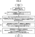
- FIG. 3 is a flowchart of an example of the attitude of the flying mobile body and the movement control method according to the first embodiment of the present invention.
- the connecting member 39 of the flying mobile body 3 is inserted into the launch rail 21 of the launch pad 2 so that both are engaged, and the flying mobile body 3 is installed on the launch pad 2 (S1).
- control unit 37 generates angular momentum by driving and rotating the wheel 33 (S2).
- control unit 37 causes the main engine 35 to be injected while continuing to generate the angular momentum by continuing the rotation of the wheel 33, and the main engine 35 generates thrust for takeoff and flight of the flying mobile body 3. (S3).
- the flying vehicle 3 slides along the launch rail 21, takes off, and flies. At this time, since it slides along the rail and takes off, the flight movement direction is controlled to a certain extent in the longitudinal direction of the launch rail 21.
- the direction of the rotation axis of the wheel 33 is further arranged to be the same as the longitudinal direction of the launch rail and the direction of the thrust that the main engine 35 should generate, and the flying vehicle 3 Since angular momentum continues to be generated before takeoff of the vehicle, even if a deviation occurs between the direction of thrust that the main engine 35 should generate (the direction of the rotation axis of the wheel 33) and the direction of thrust that is actually generated, the flight The mobile body 3 can take off and continue to fly with a stable posture.
- J 3 moment of inertia about the propulsion axis of the fuselage of the flying movable body 3
- J 1 inertia around the J 3 axes perpendicular the axis of the fuselage of the flying mobile 3
- J 2 Moment of inertia around the axis perpendicular to the J 3 and J 1 axes of the flying vehicle 3
- J h Moment of inertia around the rotation axis of the wheel
- ⁇ 1 J 1 of the flying vehicle 3
- ⁇ 2 Rotational angular velocity around the same axis as J 2 of the flying vehicle 3
- ⁇ 3 Rotational angular velocity around the same axis as J 3 of the flying vehicle 3
- ⁇ h Flying vehicle 3 when the J h and the rotation angular velocity around the same axis, Is established.
- the wheel 33 continued to rotate during the flight of the flying vehicle 3 and after landing, but when the wheel 33 that was rotating up to that point was stopped, the angular momentum opposite to the angular momentum generated by the wheel 33 was reversed.
- a momentum is generated in the flying vehicle 3.
- the flying moving body 3 can rotate.
- FIG. 4 is a diagram illustrating the movement of the flying mobile body 3 after landing.
- ⁇ angle rotated around the ground contact point P
- L distance between the ground contact point P and the center of gravity CG of the flying vehicle 3
- m total mass of the flying vehicle 3
- g gravitational acceleration
- J flying vehicle 3
- the flying vehicle 3 is stopped when the wheel 33 is stopped. viii if it is possible to obtain a sufficient rotational velocity alpha h to rotate 22,5 ° or more around the axis of the prism can be rotated moving the projectile moving body 3 overcomes the force of gravity.
- the flying vehicle can be reduced by reducing the rotation speed of the wheel 33 without reducing the rotation speed of the wheel 33 until the rotation of the wheel 33 is stopped.
- the flying vehicle 3 can be rotated. Conversely, by providing a plurality of wheels on the flying vehicle, and driving the wheel that was not driven, the angular momentum generated by the wheel is increased, so that the flying vehicle 3 is moved around the axis of the octagonal column. If the rotation angular acceleration ⁇ h that is sufficient to rotate 22.5 ° or more can be obtained, the flying vehicle 3 can be rotated in the reverse direction. After the flying moving body 3 is temporarily stopped, the flying moving body 3 may be rotated in the reverse direction by increasing the angular momentum generated by the wheel.
- the flying mobile body can rotate after the landing of the flying mobile body, it is possible to move the distance less than the minimum flying distance, and there is a deviation between the landing point and the target arrival point. You can correct the position and work around the landing point.
- the posture of the flying mobile body from take-off to landing can be stabilized with high accuracy, the posture of the flying mobile body at the time of landing can be predicted. Therefore, it is possible to apply the structure for impact mitigation at the time of landing to a part rather than the entire flying mobile body. This also makes it possible to reduce the weight of the flying vehicle.
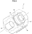
- FIG. 5 is a perspective view of a flying vehicle according to the second embodiment of the present invention.
- the configuration of the flying mobile body 3 ′ other than the casing 31 ′, which is the outer shell structure of the flying mobile body 3 ′, is the same as that of FIG. 2, and in FIG. The description of the same parts as those in the first embodiment is omitted.
- the flying vehicle 3 ′ has a shape of the casing 31 ′, and an octagonal prism in which a part of the casing 31 ′ is chamfered at four corners.
- the main engine 35 is configured to be covered with a casing 31 ′.
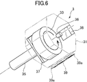
- FIG. 6 is a perspective view of a flying vehicle according to the third embodiment of the present invention.
- the configuration of the flying vehicle 3 '' is the same as that of FIG. 2 except that the reverse injection engine 36 is further provided.
- FIG. 6 portions corresponding to those of FIG. Description of the same parts as those in the first embodiment is omitted.
- the flying vehicle 3 ′′ includes a reverse injection engine 36.
- the reverse injection engine 36 is a rocket engine (thruster) that is a reverse propulsion device that generates thrust against the thrust of the main engine 35 that is a propulsion device, and is connected to the casing 31.
- the reverse injection engine 36 has a cylindrical shape and generates thrust upward in the axial direction by injection.
- the reverse injection engine 36 is disposed such that the direction of thrust that the reverse injection engine 36 should generate is the same as the direction of the rotation axis of the wheel 33.
- the reverse injection engine 36 may be composed of a plurality of rocket engines, and in this case, the direction of the combined thrust that should be generated by the plurality of rocket engines is arranged to be the same as the direction of the rotation axis of the wheel 33. It only has to be.
- the rotation axis of the wheel 33, the octagonal column casing 31, the main engine 35, and the reverse injection engine 36 indicate that the direction of the rotation axis of the wheel 33 is the axis of the octagonal column casing 31 and the thrust that the main engine 35 should generate.
- the reverse propulsion device is not limited to a cylindrical rocket engine, and may be any suitable reverse propulsion device.
- FIG. 7 is a conceptual diagram of a flying mobile object posture and movement control method according to the third embodiment of the present invention.
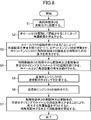
- FIG. 8 is a flowchart of an example of the attitude and movement control method of the flying moving body according to the third embodiment of the present invention.
- the steps other than the control step related to the reverse injection are the same as those in FIG. 3, and the same reference numerals are given to the portions corresponding to FIG. 3 in FIG. Is omitted.
- the control unit 37 reverses based on the detection information such as the triaxial angular velocity and acceleration from the IMU and the delta buoy of the reverse injection engine 36.
- the reverse injection timing of the injection engine 36 is calculated (S5). This point will be described in detail below.
- the flying vehicle 3 '' Even if the flying vehicle 3 '' vibrates, the flying vehicle 3 '' performs free-falling behavior in the translational direction (x direction in FIG. 8) after the injection of the main engine is completed.
- the attitude of the flying moving body 3 '' remains stable in the direction of the rotation axis of the wheel 33, and the flying moving body 3 '' continues to fly. Therefore, the direction of thrust to be generated by the reverse injection engine 36 during the flight of the flying vehicle 3 ′′ is arranged to be the same as the direction of the rotation axis of the wheel 33. The direction remains stable.
- the translational movement of the flying vehicle 3 '' can be simply considered as a free fall movement.
- g gravitational acceleration
- t 0 current time
- t l time to land at the target arrival point of the flying vehicle 3 ′′ with reference to the current time
- t b flying vehicle 3 ′′ has reached the target
- ⁇ x distance in the x direction from the current position of the flying vehicle 3 ′′ to the target arrival point
- ⁇ z the flying vehicle 3
- v x (t) the velocity in the x direction at time t of the flying vehicle 3 ′′
- v z (t) the flying vehicle 3 ′′
- v 0x velocity in the
- ⁇ x, ⁇ z, v x ( t), v z (t), v 0x, v 0z is obtained from the detection information of IMU38, ⁇ v x, ⁇ v z, since it is possible to use for example a nominal value.
- the control unit 37 performs the injection of the reverse injection engine 36 after the time t b from the time when the time t b is calculated (S6).
- the reverse injection engine 36 may be injected when the calculated t b becomes zero.
- t b t th , where t th is the delay time.
- the control unit 37 may issue an injection instruction for the reverse injection engine 36.
- the attitude of the flying mobile body 3 '' is constant during the flight of the flying mobile body 3 ''.
- the attitude prediction using a known Kalman filter based on detection information from the IMU and the like is assumed. If the attitude of the flying mobile body 3 ′′ is predicted by a method or the like, more accurate reverse injection timing can be calculated.
- the flying mobile body can be landed on the target arrival point more accurately.
- the shape of the casing may be any appropriate shape as long as the flying mobile body can rotate on the landing surface by controlling the angular momentum generated by the wheel.
- the shape of the housing may be an n prism (n is an integer of 3 or more) whose axis is the same as the rotation axis of the wheel.
- n is an integer of 3 or more
- the larger the value of n the smaller the angular momentum that the wheel needs to generate in order to rotate the flying moving body on the landing surface, but the flying moving body is stopped because the posture is not stable. It becomes difficult.
- the shape of the casing is a cylinder, but it is difficult to stop at a desired position unless a structure that increases the frictional force is added to the surface of the casing. Is difficult.
- the angular momentum that the wheel needs to generate in order to rotate the flying vehicle on the landing surface increases, and in relation to the angular momentum generation and braking performance of the wheel, There is a case where the flying mobile body cannot be rotated on the landing surface.
- the shape of the housing is the same as that of the second embodiment as long as at least a portion that contacts the landing surface when the flying mobile body rotates on the landing surface is configured as an n-prism.
- a part of the housing may be configured as a shape other than the n-prism.
- the outer shell structure of the flying mobile body is a housing that accommodates the device.
- the outer shell structure of the flying mobile body is not limited to this, and for example, accommodates the device. It is good also as an impact buffering member provided in the outer side of the housing.
Landscapes
- Engineering & Computer Science (AREA)
- Aviation & Aerospace Engineering (AREA)
- Remote Sensing (AREA)
- Chemical & Material Sciences (AREA)
- Combustion & Propulsion (AREA)
- Transportation (AREA)
- Mechanical Engineering (AREA)
- Control Of Position, Course, Altitude, Or Attitude Of Moving Bodies (AREA)
Abstract
飛翔移動体であって、外殻構造と、ホイールと、推進装置と、制御ユニットとを備え、前記ホイールは、その回転軸線の方向が、前記推進装置が発生すべき推力の方向と同一となるように配置され、前記制御ユニットは、前記ホイールに角運動量を発生させた後に、前記ホイールに角運動量の発生を続けさせつつ、前記推進装置に、前記飛翔移動体の離陸及び飛翔のための推力を発生させる飛翔移動体。
Description
この発明は、飛翔移動体、飛翔移動体発射システム、飛翔移動体の姿勢制御方法に関する。
従来、月・惑星探査機としてローバーが用いられてきた(例えば、下記非特許文献1参照)。しかしながら、クレータの縁、山、岩等の粗い地形における探査では、ローバーは走行困難となる場合があった。また、粗い地形だけでなく砂や泥などの地形においても、ローバーは走行困難となる場合があった。
さらに、地球上の災害現場においても、ローバーを災害救助車として用いることが考えられるが、災害現場においては車両が走行困難となる場合がある。
そのため、走行困難な地形を飛び越えて目標地点へ到達することが可能な飛翔移動体が求められている。
さらに、地球上の災害現場においても、ローバーを災害救助車として用いることが考えられるが、災害現場においては車両が走行困難となる場合がある。
そのため、走行困難な地形を飛び越えて目標地点へ到達することが可能な飛翔移動体が求められている。
本発明者らは、走行困難な地形を飛び越えて目標地点まで飛翔することが可能である、小型・軽量な飛翔移動体を提案した(下記特許文献1参照)。
K. Yoshida and B. Wilcox, Chap.45: Space Robots and Systems, inB. Siciliano and O. Khatib (Eds.), Springer Handbook of Robotics, Springer, 2008.
上述のように、本発明者らによって、目的地まで飛翔して移動可能な飛翔移動体が実現された。しかしながら、更に精度よく目標到達地点に飛翔・着陸可能となる飛翔体が求められている。
また、飛翔移動体においては、最小飛翔距離以下の移動が困難であるため、着陸点と目標到達地点とにずれが生じた場合の位置修正や、着陸点の周囲へ移動して作業を行うことが困難であった。
そこで、本発明は、更に精度よく目標到達地点へ飛翔・着陸可能な飛翔移動体及びその発射システムを提供することを目的の1つとする。
また、本発明は、着陸後に最小飛翔距離以下の移動が容易に可能となる飛翔移動体を提供することを目的の1つとする。
本発明の1つの態様は、飛翔移動体であって、外殻構造と、ホイールと、推進装置と、制御ユニットとを備え、前記ホイールは、その回転軸線の方向が、前記推進装置が発生すべき推力の方向と同一となるように配置され、前記制御ユニットは、前記ホイールに角運動量を発生させた後に、前記ホイールに角運動量の発生を続けさせつつ、前記推進装置に、前記飛翔移動体の離陸及び飛翔のための推力を発生させる飛翔移動体を提供するものである。
前記外殻構造は、前記ホイールの発生する角運動量の制御によって、着陸面上において前記飛翔移動体を回転移動可能とする形状を有するものとすることができる。
前記ホイールの発生する角運動量の制御は、前記ホイールの停止であるものとすることができる。
前記飛翔移動体の前記回転移動の方向は、前記ホイールの回転軸線に対して垂直であるものとすることができる。
前記外殻構造は、前記着陸面上において前記飛翔移動体が回転移動する際に前記着陸面と接する少なくとも一部が八角柱として構成され、該八角柱の軸の方向が、前記ホイールの回転軸線の方向と同一であるものとすることができる。
前記制御ユニットは、前記飛翔移動体の着陸時又は着陸後の所定のタイミングまで前記ホイールに角運動量の発生を続けさせ、前記飛翔移動体の着陸時又は着陸後の所定のタイミングに前記ホイールの発生する角運動量を制御することによって、前記着陸面上において前記飛翔移動体を回転移動させるものとすることができる。
前記飛翔移動体は、前記推進装置の推力に抗する推力を発生させる逆推力装置を更に含み、前記逆推力装置が発生すべき推力の方向は、前記ホイールの回転軸線の方向と同一であるものとすることができる。
前記制御ユニットは、前記飛翔移動体が目標到達地点に着陸するように、前記逆推力装置に推力を発生させるものとすることができる。
前記制御ユニットは、前記飛翔移動体の着陸時又は着陸後の所定のタイミングに、前記ホイールを停止させるものとすることができる。
本発明の1つの態様は、発射レールを備えた発射台と、前記飛翔移動体とを備え、前記飛翔移動体は、前記発射レールに沿って摺動可能に、該レールに連結する連結部材を更に備える飛翔移動体発射システムを提供するものである。
本発明の1つの態様は、飛翔移動体の姿勢制御方法であって、前記飛翔移動体は、外殻構造と、ホイールと、推進装置とを備え、前記ホイールは、その回転軸線の方向が、前記推進装置が発生すべき推力の方向と同一となるように配置され、前記ホイールに角運動量を発生させるステップと、その後、前記ホイールに角運動量の発生を続けさせつつ、前記推進装置に、前記飛翔移動体の離陸及び飛翔のための推力を発生させるステップとを含む方法を提供するものである。
本発明の1つの態様は、飛翔移動体の姿勢及び移動制御方法であって、前記飛翔移動体は、外殻構造と、ホイールと、推進装置とを備え、前記ホイールは、その回転軸線の方向が、前記推進装置が発生すべき推力の方向と同一となるように配置され、前記ホイールに角運動量を発生させるステップと、その後、前記ホイールに角運動量の発生を続けさせつつ、前記推進装置に、前記飛翔移動体の離陸及び飛翔のための推力を発生させるステップと、前記飛翔移動体の着陸時又は着陸後の所定のタイミングまで前記ホイールに角運動量の発生を続けさせるステップと、前記飛翔移動体の着陸時又は着陸後の所定のタイミングに前記ホイールの発生する角運動量を制御することによって、着陸面上において前記飛翔移動体を回転移動させるステップとを含む方法を提供するものである。
前記飛翔移動体は、前記推進装置の推力に抗する推力を発生させる逆推力装置を更に含み、前記逆推力装置が発生すべき推力の方向は、前記ホイールの回転軸線の方向と同一であり、前記飛翔移動体が目標到達地点に着陸するように、前記逆推力装置に推力を発生させるステップを更に含むものとすることができる。
本発明によれば、従来よりも更に精度よく目標到達地点へ飛翔・着陸可能な飛翔移動体及びその発射システムを提供することが可能となる。
また、本発明によれば、着陸後に最小飛翔距離以下の移動が容易に可能となる飛翔移動体を提供することも可能となる。
また、本発明によれば、着陸後に最小飛翔距離以下の移動が容易に可能となる飛翔移動体を提供することも可能となる。
以下、本発明の実施形態について図面を参照して説明する。
(第1の実施形態)
図1は、本発明の第1の実施形態に係る飛翔移動体発射システムの全体構成図、図2は、本発明の第1の実施形態に係る飛翔移動体の斜視図である。
図1は、本発明の第1の実施形態に係る飛翔移動体発射システムの全体構成図、図2は、本発明の第1の実施形態に係る飛翔移動体の斜視図である。
図1に示されるように本実施形態に係る飛翔移動体発射システム1は、飛翔移動体3と発射台2を備える。
発射台2は、発射レール21を備え、発射レール21の長手方向、すなわち発射仰角と発射方位角が調節可能に構成されている。そして、発射レール21に飛翔移動体3が摺動可能に取り付けられ、飛翔移動体3を発射させることができる。
飛翔移動体3は、筐体31、ホイール33、メインエンジン35、制御ユニット37、慣性計測ユニット(IMU)38を備える。
飛翔移動体3の外殻構造である筐体31は、四角柱の四隅を面取りした八角柱の形状を有している。これによって、後述のように、ホイール33の発生する角運動量の減少によって、着陸面上において飛翔移動体3が回転移動することができる。また、筐体31は、ホイール33及び制御ユニット37を収容する。
ホイール33は、その回転軸線に周りに回転し、角運動量を発生する。ホイール33は、筐体31の内部に配置されているが、その回転軸線の方向が、八角柱の筐体31の軸及びメインエンジン35が発生すべき推力の方向と同一となるように配置されている。これにより、飛翔移動体3の姿勢が安定し、目標到達地点への飛行安定性に優れる。ホイール33の回転軸線、八角柱の筐体31及びメインエンジン35は、ホイール33の回転軸線の方向が、八角柱の筐体31の軸及びメインエンジン35が発生すべき推力の方向と同一となるように配置されていれば、同軸に配置されていなくても良い。
メインエンジン35は、推進装置であるロケットエンジン(スラスタ)であり、筐体31に接続されている。メインエンジン35は、円柱の形状を有しており、噴射によってその軸方向下方に推力を発生する。推進装置は、円柱形のロケットエンジンに限定されるものではなく、適切な任意の推進装置とすることができる。
制御ユニット37は、ホイール33の回転速度を制御することにより、発生する角運動量を制御する。ホイールの発生する角運動量の制御は、飛翔移動体3に複数のホイールを設けて、駆動するホイールの数を変更することによって行ってもよい。また、制御ユニット37は、メインエンジン35の発生する推力を制御する。制御ユニット37は、IMU38からの3軸の角速度や加速度等の検出情報等を取得し、この情報に基づいて各種計算を行ったり、取得した情報や計算結果に基づいて、飛翔移動体3の各部の制御等を行う。
連結部材39は、長手方向に延びる板状部材であり、筐体31の側面に取り付けられている。そして、連結部材39は、筐体31の側面の中央部に、その長手方向が、ホイール33の回転軸線の方向と同一となるように配置されている。
連結部材39には凸状部39aが形成されている。一方、発射レール21は、その断面が、連結部材39の凸状部39aと相補的な形状の溝部21aが形成されている長尺状のレールである。連結部材39の凸状部を発射レール21の溝部21aに、両者が係合するように挿入することによって、飛翔移動体3を発射台2に設置することができ、また飛翔移動体3は、発射レール21に沿って摺動することができる。
以上の装置構成を前提に、本発明の第1の実施形態に係る飛翔移動体及び飛翔移動体発射システムの動作原理、並びに飛翔移動体及び飛翔移動体発射システムを用いた飛翔移動体の姿勢及び移動制御方法の例を図1~4を参照して、以下に説明する。図3は、本発明の第1の実施形態に係る飛翔移動体の姿勢及び移動制御方法の例のフローチャートである。
まず、飛翔移動体3の連結部材39を発射台2の発射レール21に、両者が係合するように挿入し、飛翔移動体3を発射台2に設置する(S1)。
続いて、制御ユニット37が、ホイール33を駆動して回転させることによって角運動量を発生させる(S2)。
その後、制御ユニット37は、ホイール33の回転を続けさせることによって角運動量の発生を続けさせつつ、メインエンジン35を噴射させ、メインエンジン35に飛翔移動体3の離陸及び飛翔のための推力を発生させる(S3)。飛翔移動体3は、発射レール21に沿って滑走し、離陸し、飛翔する。このとき、レールに沿って滑走して離陸するので、飛翔移動方向が、発射レール21の長手方向に一定程度制御される。本実施形態においては、更に、ホイール33の回転軸線の方向が、発射レールの長手方向とメインエンジン35が発生すべき推力の方向と同一となるように配置されており、また、飛翔移動体3の離陸の前から角運動量の発生が続いているので、メインエンジン35が発生すべき推力の方向(ホイール33の回転軸線の方向)と実際に発生する推力の方向にずれが生じても、飛翔移動体3は、姿勢が安定して、離陸し、飛翔を続けることができる。
ここで、飛翔移動体3の飛翔中において、J3:飛翔移動体3の機体の推進方向軸周りの慣性モーメント、J1:飛翔移動体3の機体のJ3軸と垂直な軸周りの慣性モーメント、J2:飛翔移動体3の機体のJ3・J1軸と垂直な軸周りの慣性モーメント、Jh:ホイールの回転軸周りの慣性モーメント、ω1:飛翔移動体3のJ1と同一軸周りの回転角速度、ω2:飛翔移動体3のJ2と同一軸周りの回転角速度、ω3:飛翔移動体3のJ3と同一軸周りの回転角速度、ωh:飛翔移動体3のJhと同一軸周りの回転角速度としたとき、
 が成立する。
所定時間が経過すると、飛翔移動体3は着陸するが、制御ユニット37は、飛翔移動体3の飛翔中から着陸時又は着陸後の所定のタイミングまでホイール33の回転を続けさせ、ホイール33に角運動量の発生を続けさせる(S4)。制御ユニット37が、飛翔移動体3の着陸時又は着陸後の所定のタイミングでホイールの回転を停止させることにより、発生する角運動量をゼロとすると、飛翔移動体3は天体の表面等の着陸面上で、ホイール33の回転軸線に対して垂直な方向に回転移動を開始する(S7)。この点について、以下、詳細に説明する。
ホイール33は、飛翔移動体3の飛翔中及び着陸後を通じて回転し続けていたところ、それまで回転していたホイール33を停止させると、ホイール33が発生していた角運動量とは逆向きの角運動量が飛翔移動体3に発生する。この飛翔移動体3に発生した角運動量によるトルクの大きさが、重力によるトルクより大きいと、飛翔移動体3は回転移動することができる。
図4は、飛翔移動体3の着陸後の運動を示す図である。θ:接地点Pを中心に回転した角度、L:接地点Pと飛翔移動体3の重心CGとの距離、m:飛翔移動体3の全質量、g:重力加速度、J:飛翔移動体3の主慣性モーメント、τ:ホイールにより発生するトルクとしたとき、接地点Pを支点とした回転運動の方程式は、
 となる。
となる。
また、Jh:ホイールの回転軸周りの慣性モーメント、αh:ホイール回転角加速度とすると、
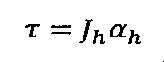 が成立する。
したがって、筐体31の形状が、その軸の方向がホイール33の回転軸線の方向と同一である、四角柱を面取りした八角柱であるので、ホイール33を停止させたときに、飛翔移動体3を八角柱の軸周りに22、5°以上回転させるのに十分な回転角速度αhを得ることができれば、重力に打ち勝って飛翔移動体3を回転移動させることができる。ここで、ホイールの角運動量発生・ブレーキ性能に余裕があれば、ホイール33の回転を停止させるまでホイール33の回転速度を減少させなくとも、ホイール33の回転速度を減少させることによって、飛翔移動体3を八角柱の軸周りに22.5°以上回転させるのに十分な回転角加速度αhを得ることができれば、飛翔移動体3を回転移動させることができる。また、逆に、飛翔移動体にホイールを複数設け、そのうちの駆動していなかったホイールを駆動させる等によって、ホイールの発生する角運動量を増加させることによって、飛翔移動体3を八角柱の軸周りに22.5°以上回転させるのに十分な回転角加速度αhを得ることができれば、飛翔移動体3を逆方向に回転移動させることができる。飛翔移動体3が一旦停止した後に、ホイールの発生する角運動量を増加させることによって、飛翔移動体3を逆方向に回転移動させてもよい。
本実施形態によれば、飛翔移動体の着陸後に、飛翔移動体が回転移動することができるので、最小飛翔距離以下の距離の移動が可能となり、着陸点と目標到達地点にずれが生じた場合の位置修正や、着陸点の周囲で作業を行うことができる。
また、本実施形態によれば、飛翔移動体の離陸から着陸までの姿勢を精度よく安定させることができるので、着陸時の飛翔移動体の姿勢の予測が可能となる。よって、着陸時の衝撃緩和のための構成を、飛翔移動体全体でなく一部に絞って施すことが可能となる。また、これにより、飛翔移動体の軽量化を図ることができる。
(第2の実施形態)
図5は、本発明の第2の実施形態に係る飛翔移動体の斜視図である。本実施形態において、飛翔移動体3'の外殻構造である筐体31'以外の飛翔移動体3'の構成は図2と同様であり、図5において図2と対応する部分には同一符号を付し、第1の実施形態と同様の部分の説明は省略する。
図5は、本発明の第2の実施形態に係る飛翔移動体の斜視図である。本実施形態において、飛翔移動体3'の外殻構造である筐体31'以外の飛翔移動体3'の構成は図2と同様であり、図5において図2と対応する部分には同一符号を付し、第1の実施形態と同様の部分の説明は省略する。
図5に示されるように、本発明の第2の実施形態に係る飛翔移動体3'は、筐体31'の形状を、筐体31'の一部が四角柱の四隅を面取りした八角柱として構成される、斜方立方八面体様とし、メインエンジン35が筐体31'により覆われるように構成したものである。
このような構成により、筐体31'が、着陸時にメインエンジン35が受ける衝撃を緩和することができる。
(第3の実施形態)
図6は、本発明の第3の実施形態に係る飛翔移動体の斜視図である。本実施形態において、逆噴射エンジン36が更に備えられている以外の飛翔移動体3''の構成は図2と同様であり、図6において図2と対応する部分には同一符号を付し、第1の実施形態と同様の部分の説明は省略する。
図6は、本発明の第3の実施形態に係る飛翔移動体の斜視図である。本実施形態において、逆噴射エンジン36が更に備えられている以外の飛翔移動体3''の構成は図2と同様であり、図6において図2と対応する部分には同一符号を付し、第1の実施形態と同様の部分の説明は省略する。
図6に示されるように、本発明の第3の実施形態に係る飛翔移動体3''は、逆噴射エンジン36を備える。逆噴射エンジン36は、推進装置であるメインエンジン35の推力に抗する推力を発生させる逆推進装置であるロケットエンジン(スラスタ)であり、筐体31に接続されている。逆噴射エンジン36は、円柱の形状を有しており、噴射によってその軸方向上方に推力を発生する。逆噴射エンジン36は、逆噴射エンジン36が発生すべき推力の方向が、ホイール33の回転軸線の方向と同一となるように配置されている。逆噴射エンジン36は、複数のロケットエンジンから構成されてもよく、その場合、複数のロケットエンジンが発生すべきの合成推力の方向が、ホイール33の回転軸線の方向と同一となるように配置されていればよい。ホイール33の回転軸線、八角柱の筐体31、メインエンジン35、逆噴射エンジン36は、ホイール33の回転軸線の方向が、八角柱の筐体31の軸、メインエンジン35が発生すべき推力の方向及び逆噴射エンジン36が発生すべき推力の方向と同一となるように配置されていれば、同軸に配置されていなくても良い。逆推進装置は、円柱形のロケットエンジンに限定されるものではなく、適切な任意の逆推進装置とすることができる。
以上の装置構成を前提に、本発明の第3の実施形態に係る飛翔移動体及び飛翔移動体発射システムの動作原理、並びに飛翔移動体及び飛翔移動体発射システムを用いた飛翔移動体の姿勢及び移動制御方法の例を図1~4、6~8を参照して、以下に説明する。図7は、本発明の第3の実施形態に係る飛翔移動体の姿勢及び移動制御方法の概念図である。また、図8は、本発明の第3の実施形態に係る飛翔移動体の姿勢及び移動制御方法の例のフローチャートである。本実施形態において、逆噴射に係る制御ステップ以外のステップは図3と同様であり、図8において図3と対応する部分には同一符号を付し、第1の実施形態と同様の部分の説明は省略する。
飛翔移動体3''の離陸後において、メインエンジン35の噴射の終了後、制御ユニット37は、IMUからの3軸の角速度や加速度等の検出情報や逆噴射エンジン36のデルタブイに基づいて、逆噴射エンジン36の逆噴射のタイミングを計算する(S5)。この点について、以下、詳細に説明する。
飛翔移動体3''が振動していても、並進方向(図8のx方向)については、メインエンジンの噴射終了後は、飛翔移動体3''は自由落下のふるまいを行う。
上で述べたように、ホイール33の回転を続けさせることによって、飛翔移動体3''の姿勢はホイール33の回転軸線の方向のまま安定して、飛翔移動体3''は飛翔を続ける。よって、飛翔移動体3''の飛翔中において、逆噴射エンジン36が発生すべき推力の方向は、ホイール33の回転軸線の方向と同一となるように配置されているから、ホイール33の回転軸線の方向のまま安定している。
したがって、メインエンジンの噴射終了後に逆噴射エンジン36の噴射を行った場合は、飛翔移動体3''の並進方向の運動は、単純に自由落下運動と考えればよいから、
 が成立する。ここで、g:重力加速度、t0:現在時刻、tl:現在時刻を基準とした飛翔移動体3''の目標到達地点に着陸する時刻、tb:飛翔移動体3''が目標到達地点に着陸するための現在時刻を基準とした逆噴射エンジン36を噴射すべき時刻、Δx:飛翔移動体3''の現在位置から目標到達地点までのx方向の距離、Δz:飛翔移動体3''の現在位置から目標到達地点までのz方向の距離、vx(t):飛翔移動体3''の時刻tにおけるx方向の速度、vz(t):飛翔移動体3''の時刻tにおけるz方向の速度、v0x:飛翔移動体3''の現在時刻t0におけるx方向の速度、v0z:飛翔移動体3''の現在時刻t0におけるz方向の速度、Δvx:逆噴射エンジン36のデルタブイのx方向の成分、Δvz:逆噴射エンジン36のデルタブイのz方向の成分である。
よって、Δx、Δz、vx(t)、vz(t)、v0x、v0zは、IMU38の検出情報から得られ、Δvx、Δvzは、例えば公称値を用いることができるので、上式を解くことにより、飛翔移動体3''が目標到達地点に着陸するための現在時刻を基準とした逆噴射すべき時刻tbを計算することができる。そして、計算された時刻tbに逆噴射を行えば、飛翔移動体3''は、並進方向について、目標到達地点と同じ座標の地点に着陸する。
続いて、制御ユニット37は、時刻tbを計算した時刻から時間tb後に逆噴射エンジン36の噴射を行う(S6)。ここで、制御ユニット37が、時刻tbを常時リアルタイムで計算する構成を採用すると、計算されたtbがゼロとなった時点で逆噴射エンジン36を噴射すればよい。この場合、制御ユニット37の逆噴射エンジン36の噴射指示から実際に逆噴射エンジン36が噴射を開始するまでに遅延が発生する場合は、遅延時間をtthとすると、tb=tthとなった時点で、制御ユニット37は、逆噴射エンジン36の噴射指示を出せばよい。
上記実施形態においては、飛翔移動体3''の飛翔中において、飛翔移動体3''の姿勢は一定であると仮定したが、IMUからの検出情報等に基づく公知のカルマンフィルタを用いた姿勢予測方法等によって飛翔移動体3''の姿勢予測を行えば、より正確な逆噴射タイミングの算出を行うことができる。
本実施形態によれば、飛翔移動体をより正確に目標到達地点に着陸させることができる。
上記の各実施形態において、筐体の形状は、ホイールの発生する角運動量の制御によって、着陸面上において飛翔移動体が回転移動することを可能とする形状であれば、適切な任意の形状を用いることができる。例えば、筐体の形状は、その軸がホイールの回転軸線と同一であるn角柱(nは3以上の整数)としてもよい。この場合、nの値が大きいほど、着陸面上において飛翔移動体を回転移動させるために、ホイールが発生する必要がある角運動量は小さくなるが、姿勢が安定しないために飛翔移動体を停止させるのが難しくなる。特に、nを無限大にした場合は筐体の形状は円柱となるが、筐体の表面に摩擦力を増大させる構造を付加しないと、所望の位置で停止させることが困難であり、また登坂が困難である。逆に、nの値が小さいと、着陸面上において飛翔移動体を回転移動させるために、ホイールが発生する必要がある角運動量は大きくなり、ホイールの角運動量発生・ブレーキ性能との関係で、着陸面上において飛翔移動体を回転移動させることができない場合が生じる。また、例えば、筐体の形状は、筐体が着陸面上において飛翔移動体が回転移動する際に着陸面と接する少なくとも一部がn角柱として構成されていれば、第2の実施形態のように、筐体の一部がn角柱以外の形状として構成されてもよい。
上記の各実施形態において、飛翔移動体の外殻構造を、機器を収容する筐体としたが、飛翔移動体の外殻構造は、これに限定されるものでなく、例えば、機器を収容する筐体の外側に設けられた衝撃緩衝部材としてもよい。
以上、本発明について、例示のためにいくつかの実施形態に関して説明してきたが、本発明はこれに限定されるものでなく、本発明の範囲から逸脱することなく、形態及び詳細について、様々な変形及び修正を行うことができることは、当業者に明らかであろう。
1 飛翔移動体発射システム
2 発射台
21 発射レール
21a 溝部
3、3'、3' 飛翔移動体
31、31' 筐体
33 ホイール
35 メインエンジン
36 逆噴射エンジン
37 制御ユニット
38 IMU
39 連結部材
39a 凸状部
2 発射台
21 発射レール
21a 溝部
3、3'、3' 飛翔移動体
31、31' 筐体
33 ホイール
35 メインエンジン
36 逆噴射エンジン
37 制御ユニット
38 IMU
39 連結部材
39a 凸状部
Claims (13)
- 飛翔移動体であって、
外殻構造と、
ホイールと、推進装置と、制御ユニットと、
を備え、
前記ホイールは、その回転軸線の方向が、前記推進装置が発生すべき推力の方向と同一となるように配置され、
前記制御ユニットは、前記ホイールに角運動量を発生させた後に、前記ホイールに角運動量の発生を続けさせつつ、前記推進装置に、前記飛翔移動体の離陸及び飛翔のための推力を発生させる、
飛翔移動体。 - 前記外殻構造は、前記ホイールの発生する角運動量の制御によって、着陸面上において前記飛翔移動体を回転移動可能とする形状を有する請求項1に記載の飛翔移動体。
- 前記ホイールの発生する角運動量の制御は、前記ホイールの停止である請求項2に記載の飛翔移動体。
- 前記飛翔移動体の前記回転移動の方向は、前記ホイールの回転軸線に対して垂直である請求項2又は3に記載の飛翔移動体。
- 前記外殻構造は、前記着陸面上において前記飛翔移動体が回転移動する際に前記着陸面と接する少なくとも一部が八角柱として構成され、該八角柱の軸の方向が、前記ホイールの回転軸線の方向と同一である請求項2~4のいずれか1項に記載の飛翔移動体。
- 前記制御ユニットは、前記飛翔移動体の着陸時又は着陸後の所定のタイミングまで前記ホイールに角運動量の発生を続けさせ、前記飛翔移動体の着陸時又は着陸後の所定のタイミングに前記ホイールの発生する角運動量を制御することによって、前記着陸面上において前記飛翔移動体を回転移動させる請求項1~5のいずれか1項に記載の飛翔移動体。
- 前記制御ユニットは、前記飛翔移動体の着陸時又は着陸後の所定のタイミングに、前記ホイールを停止させる請求項6に記載の飛翔移動体。
- 前記推進装置の推力に抗する推力を発生させる逆推力装置を更に含み、
前記逆推力装置が発生すべき推力の方向は、前記ホイールの回転軸線の方向と同一である請求項1~7のいずれか1項に記載の飛翔移動体。 - 前記制御ユニットは、前記飛翔移動体が目標到達地点に着陸するように、前記逆推力装置に推力を発生させる請求項8に記載の飛翔移動体。
- 発射レールを備えた発射台と、
請求項1~9のいずれか1項の飛翔移動体と、
を備え、
前記飛翔移動体は、前記発射レールに沿って摺動可能に、該レールに連結する連結部材を更に備える、
飛翔移動体発射システム。 - 飛翔移動体の姿勢制御方法であって、
前記飛翔移動体は、外殻構造と、ホイールと、推進装置とを備え、
前記ホイールは、その回転軸線の方向が、前記推進装置が発生すべき推力の方向と同一となるように配置され、
前記ホイールに角運動量を発生させるステップと、
その後、前記ホイールに角運動量の発生を続けさせつつ、前記推進装置に、前記飛翔移動体の離陸及び飛翔のための推力を発生させるステップと、
を含む方法。 - 飛翔移動体の姿勢及び移動制御方法であって、
前記飛翔移動体は、外殻構造と、ホイールと、推進装置とを備え、
前記ホイールは、その回転軸線の方向が、前記推進装置が発生すべき推力の方向と同一となるように配置され、
前記ホイールに角運動量を発生させるステップと、
その後、前記ホイールに角運動量の発生を続けさせつつ、前記推進装置に、前記飛翔移動体の離陸及び飛翔のための推力を発生させるステップと、
前記飛翔移動体の着陸時又は着陸後の所定のタイミングまで前記ホイールに角運動量の発生を続けさせるステップと、
前記飛翔移動体の着陸時又は着陸後の所定のタイミングに前記ホイールの発生する角運動量を制御することによって、着陸面上において前記飛翔移動体を回転移動させるステップと、
を含む方法。 - 前記飛翔移動体は、前記推進装置の推力に抗する推力を発生させる逆推力装置を更に含み、
前記逆推力装置が発生すべき推力の方向は、前記ホイールの回転軸線の方向と同一であり、
前記飛翔移動体が目標到達地点に着陸するように、前記逆推力装置に推力を発生させるステップを更に含む請求項11又は12に記載の方法。
Applications Claiming Priority (4)
| Application Number | Priority Date | Filing Date | Title |
|---|---|---|---|
| JP2016-172882 | 2016-09-05 | ||
| JP2016172882 | 2016-09-05 | ||
| JP2017-104820 | 2017-05-26 | ||
| JP2017104820A JP2018039495A (ja) | 2016-09-05 | 2017-05-26 | 飛翔移動体 |
Publications (1)
| Publication Number | Publication Date |
|---|---|
| WO2018043737A1 true WO2018043737A1 (ja) | 2018-03-08 |
Family
ID=61301169
Family Applications (1)
| Application Number | Title | Priority Date | Filing Date |
|---|---|---|---|
| PCT/JP2017/031772 Ceased WO2018043737A1 (ja) | 2016-09-05 | 2017-09-04 | 飛翔移動体 |
Country Status (1)
| Country | Link |
|---|---|
| WO (1) | WO2018043737A1 (ja) |
Citations (3)
| Publication number | Priority date | Publication date | Assignee | Title |
|---|---|---|---|---|
| JPS6088700A (ja) * | 1983-10-20 | 1985-05-18 | 三菱電機株式会社 | 人工衛星のガスジエツト装置 |
| JPH06156399A (ja) * | 1992-07-20 | 1994-06-03 | General Electric Co <Ge> | 姿勢制御システム、及び人工衛星の方向を制御する方法 |
| JP2003170900A (ja) * | 2001-12-07 | 2003-06-17 | Ishikawajima Harima Heavy Ind Co Ltd | ロケットの組立と打ち上げ方法及びその設備 |
-
2017
- 2017-09-04 WO PCT/JP2017/031772 patent/WO2018043737A1/ja not_active Ceased
Patent Citations (3)
| Publication number | Priority date | Publication date | Assignee | Title |
|---|---|---|---|---|
| JPS6088700A (ja) * | 1983-10-20 | 1985-05-18 | 三菱電機株式会社 | 人工衛星のガスジエツト装置 |
| JPH06156399A (ja) * | 1992-07-20 | 1994-06-03 | General Electric Co <Ge> | 姿勢制御システム、及び人工衛星の方向を制御する方法 |
| JP2003170900A (ja) * | 2001-12-07 | 2003-06-17 | Ishikawajima Harima Heavy Ind Co Ltd | ロケットの組立と打ち上げ方法及びその設備 |
Similar Documents
| Publication | Publication Date | Title |
|---|---|---|
| RU2737644C2 (ru) | Энергоэффективное маневрирование спутника | |
| JP2016088121A (ja) | 観測装置 | |
| US9919792B2 (en) | Vehicle attitude control using jet paddles and/or movable mass | |
| WO2011131733A2 (fr) | Engin gyropendulaire à propulsion compensatoire et collimation de gradient fluidique, multi-milieux, multimodal, à décollage et atterrissage vertical | |
| CN103662091A (zh) | 一种基于相对导航的高精度安全着陆制导方法 | |
| CN106931967A (zh) | 一种助推‑滑翔式临近空间飞行器的捷联惯性导航方法 | |
| CN105674988B (zh) | 一种mems等效单轴旋转惯导的传递对准方法 | |
| JP2012137082A (ja) | 遠心力による推進力発生装置 | |
| Rew et al. | Control system design of the Korean lunar lander demonstrator | |
| CN103884333B (zh) | 一种深空探测自主导航初始基准捕获方法 | |
| WO2018043737A1 (ja) | 飛翔移動体 | |
| JP2018039495A (ja) | 飛翔移動体 | |
| Braun et al. | Advances in inertial guidance technology for aerospace systems | |
| CN105674987B (zh) | 一种mems等效单轴旋转惯导的构造方法 | |
| RU2015101477A (ru) | Способ управления движением космического аппарата на активном участке его выведения на орбиту искусственного спутника планеты | |
| RU2581787C2 (ru) | Способ стабилизации слабодемпфированного неустойчивого объекта управления и устройство для его осуществления | |
| RU2559430C2 (ru) | Способ управления сходом космического аппарата с орбиты искусственного спутника земли | |
| Tanishima et al. | Concept and mechanism of the tendon actuated versatile debris gripper | |
| Miller | Optimal trajectory planning for the apollo moon landing: Descent, ascent, and aborts | |
| JP2019099110A (ja) | 飛翔移動体 | |
| US20200216166A1 (en) | Terminal Approach Angle Guidance for Unpowered Vehicles | |
| WO2022014694A1 (ja) | ロケット制御システム、及びロケットの着陸動作の制御方法 | |
| Kong et al. | Development and verification of algorithms for spacecraft formation flight using the SPHERES testbed: application to TPF | |
| CN116296218B (zh) | 一种双自由度支撑机构天地相关性模拟方法 | |
| RU2658070C2 (ru) | Комбинированная гравитационная система ориентации малого космического аппарата |
Legal Events
| Date | Code | Title | Description |
|---|---|---|---|
| 121 | Ep: the epo has been informed by wipo that ep was designated in this application |
Ref document number: 17846740 Country of ref document: EP Kind code of ref document: A1 |
|
| NENP | Non-entry into the national phase |
Ref country code: DE |
|
| 122 | Ep: pct application non-entry in european phase |
Ref document number: 17846740 Country of ref document: EP Kind code of ref document: A1 |