WO2018043665A1 - 脚部構造体及びこれを用いた飛翔体 - Google Patents
脚部構造体及びこれを用いた飛翔体 Download PDFInfo
- Publication number
- WO2018043665A1 WO2018043665A1 PCT/JP2017/031429 JP2017031429W WO2018043665A1 WO 2018043665 A1 WO2018043665 A1 WO 2018043665A1 JP 2017031429 W JP2017031429 W JP 2017031429W WO 2018043665 A1 WO2018043665 A1 WO 2018043665A1
- Authority
- WO
- WIPO (PCT)
- Prior art keywords
- main body
- flying object
- plane
- grounding
- axis
- Prior art date
- Legal status (The legal status is an assumption and is not a legal conclusion. Google has not performed a legal analysis and makes no representation as to the accuracy of the status listed.)
- Ceased
Links
Images





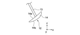

Classifications
-
- B—PERFORMING OPERATIONS; TRANSPORTING
- B64—AIRCRAFT; AVIATION; COSMONAUTICS
- B64C—AEROPLANES; HELICOPTERS
- B64C25/00—Alighting gear
- B64C25/32—Alighting gear characterised by elements which contact the ground or similar surface
-
- B—PERFORMING OPERATIONS; TRANSPORTING
- B64—AIRCRAFT; AVIATION; COSMONAUTICS
- B64G—COSMONAUTICS; VEHICLES OR EQUIPMENT THEREFOR
- B64G1/00—Cosmonautic vehicles
- B64G1/22—Parts of, or equipment specially adapted for fitting in or to, cosmonautic vehicles
-
- B—PERFORMING OPERATIONS; TRANSPORTING
- B64—AIRCRAFT; AVIATION; COSMONAUTICS
- B64U—UNMANNED AERIAL VEHICLES [UAV]; EQUIPMENT THEREFOR
- B64U60/00—Undercarriages
- B64U60/20—Undercarriages specially adapted for uneven terrain
-
- B—PERFORMING OPERATIONS; TRANSPORTING
- B64—AIRCRAFT; AVIATION; COSMONAUTICS
- B64U—UNMANNED AERIAL VEHICLES [UAV]; EQUIPMENT THEREFOR
- B64U60/00—Undercarriages
- B64U60/50—Undercarriages with landing legs
Definitions
- the present invention relates to a leg structure and a flying body using the leg structure.
- the flying object When the flying object lands, if there is a granular medium in the landing area, the grounded part of the flying object will be caught by the granular medium, and it will easily fall over.
- celestial bodies such as the moon and planets have many regions covered with granular media such as sand and regolith. Therefore, a space probe, which is a flying object for exploring celestial bodies, is likely to fall down when landing on the celestial body.
- the direction in which the impact can be absorbed is limited to a specific direction. Therefore, the impact may not be appropriately absorbed depending on the landing angle of the flying object.
- the honeycomb structure is plastically deformed, it is necessary to replace the honeycomb structure every time the flying object lands.
- the space probe will bounce due to the elasticity of the air bag when landing. In order to prevent this, it is necessary to release the gas in the airbag at the moment of landing of the space probe.
- an object of the present invention is to provide a technique for satisfactorily landing a flying object on the ground covered with a granular medium.
- the present invention provides: A leg structure that can support the main body of the flying body, A plurality of grounding portions provided around an axis orthogonal to the plane along a plane facing the main body; A plurality of connecting portions connecting the plurality of grounding portions and the main body portion; Each of the multiple grounding parts A first inclined surface facing the main body and inclined to the axial side with respect to the plane; There is provided a leg structure having a second inclined surface facing a side opposite to the main body side and inclined to the side opposite to the axis with respect to the plane.
- this leg part structure can suppress that a flying body falls forward in the advancing direction at the time of landing on a granular medium.
- the plurality of grounding portions may be provided symmetrically with respect to the axis. With this configuration, an effect of suppressing a fall upon landing can be obtained in a flying body in various landing directions.
- the axis may pass through the center of gravity of the flying object. In this configuration, the flying object can be more effectively suppressed from falling when landing.
- Each of the plurality of ground portions may be formed in a flat plate shape. With this configuration, it is possible to easily obtain the effect of suppressing the fall when landing on the flying object.
- the present invention also provides: A leg that can support a drone having a main body portion and a plurality of leg portions that extend from the main body portion and whose distal end portion is disposed around an axis orthogonal to the plane along a plane facing the main body portion.
- a substructure A plurality of grounding portions that can be attached to the tip portions of the plurality of leg portions, respectively,
- Each of the multiple grounding parts A first inclined surface facing the main body and inclined to the axial side with respect to the plane;
- a leg structure having a second inclined surface facing a side opposite to the main body side and inclined to the side opposite to the axis with respect to the plane.
- the present invention also provides: A main body, and a leg structure that can support the main body,
- the leg structure is A plurality of grounding portions provided around an axis orthogonal to the plane along a plane facing the main body;
- a plurality of connecting portions for connecting the plurality of grounding portions and the main body portion;
- Each of the multiple grounding parts A first inclined surface facing the main body and inclined to the axial side with respect to the plane;
- a flying object is provided that has a second inclined surface that faces away from the main body side and is inclined to the opposite side of the axis with respect to the plane.
- the flying object may be configured as a space probe capable of landing on a celestial body covered with a granular medium.
- the flying object may be configured as a drone that can land on the ground covered with a granular medium.
- FIG. 1 is a perspective view of a flying object 10 according to the present embodiment.
- the flying object 10 is configured as a space probe that flies in outer space and can land on a celestial body such as the moon or a planet.
- the flying body 10 includes a main body portion 11 and a plurality of leg structure bodies 12.
- the plurality of leg structures 12 are disposed on the lower side in the z-axis direction of the main body 11.
- the main body 11 is formed in a cylindrical shape having a central axis C parallel to the z axis. That is, the main body 11 has an upper and lower surface parallel to the xy plane and a side surface that is a circumferential surface extending in the z-axis direction.
- the main-body part 11 may be other than column shape, and can be made into arbitrary solid shapes. In any case, it is preferable that the central axis C passes through the center of gravity of the flying object 10.
- the main body 11 accommodates various devices. Examples of the device accommodated in the main body 11 include a device for operating the flying object 10, a device for communicating with the outside, and a device necessary for exploring celestial bodies.
- the flying object 10 may be an unmanned explorer that does not accommodate a person in the main body 11 or a manned explorer that can accommodate a person in the main body 11.
- the flying object 10 includes a plurality of leg structures 12 having a common configuration.
- Each leg structure 12 includes a connection portion 13 and a grounding portion 14.
- the connecting portion 13 is formed in an elongated rod shape having a circular cross section.
- the grounding portion 14 is configured as a foot pad formed in a disc shape.
- the leg part structure 12 supports the main body part 11 and enables the flying body 10 to stand on its own.
- the plurality of connecting portions 13 are attached to the lower surface in the z-axis direction of the main body 11 at the upper end in the z-axis direction. More specifically, the z-axis direction upper ends of the plurality of connecting portions 13 are arranged at equal intervals along the outer periphery of the lower surface of the main body portion 11. Each connecting portion 13 extends obliquely downward so as to be separated from the central axis C.
- the plurality of grounding portions 14 are disposed around the central axis C along a plane P (see FIG. 2) parallel to the xy plane disposed below the main body portion 11 in the z-axis direction.
- the leg part structure 12 holds the main body part 11 with the grounding part 14 in contact with the ground.
- the grounding portion 14 is arranged so as to be symmetric with respect to the central axis C so that the flying object 10 can be stably supported.
- connection unit 13 connects the ground unit 14 to the main body unit 11.
- the structure of the connection part 13 should just be able to connect the grounding part 14 to the main-body part 11, and can be changed variously.
- the grounding portion 14 is disposed in a state inclined with respect to the xy plane. More specifically, the z-axis direction upper surface 14a of the grounding portion 14 is configured as a first inclined surface inclined toward the central axis C side. Further, the lower surface 14b in the z-axis direction of the grounding portion 14 is configured as a second inclined surface that is inclined to the side opposite to the central axis C.
- the leg structure 12 has a symmetrical configuration with respect to the central axis C.
- the flying body 10 it is only necessary to provide a plurality of leg structure bodies 12, and the number of leg structure bodies 12 may not be four. Regardless of the number of leg structures 12, the leg structures 12 are preferably arranged so as to be symmetrical with respect to the central axis C.
- the flying object 10 can land on the ground covered with a granular medium from the ground contact part 14 of the leg structure 12.
- the grounding part 14 can implement
- details of the grounding unit 14 will be described.
- FIG. 2 is a schematic diagram showing the flying object 10 two-dimensionally.
- FIG. 2 shows a main body 11 and two leg structures 12 that face each other in the x-axis direction. Further, FIG. 2 shows a plane P parallel to the xy plane disposed below the main body 11 in the z-axis direction. As described above, the plurality of grounding portions 14 are provided along the plane P.
- the angle ⁇ of the grounding portion 14 with respect to the plane P is larger than 0 ° and smaller than 90 °.
- the grounding portion 14 has a configuration in which the upper surface 14a is inclined toward the central axis C and the lower surface 14b is inclined toward the opposite side to the central axis C as described above. A method for designing the angle ⁇ of the grounding portion 14 will be described later.
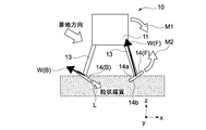
- 3 and 4 are views showing a state at the moment when the flying object 10 lands on the ground extending parallel to the xy plane covered with the granular medium. 3 and 4, the reaction force W applied to each grounding portion 14 from the granular medium is shown as a vector. The vectors of reaction force W shown in FIGS. 3 and 4 are approximate and are not accurate.
- the landing direction of the flying object 10 on the granular medium is different. That is, in FIG. 3, the landing direction of the flying object 10 is below the z-axis direction (vertical direction), and landed on the granular medium without traveling in the x-axis direction. On the other hand, in FIG. 4, the landing direction of the flying object 10 is diagonally downward to the right, and the flying object 10 lands on the granular medium while proceeding in the x-axis direction.
- the flying object 10 in the state shown in FIG. 3, it is difficult for the flying object 10 to generate a moment to fall. Further, the grounding portion 14 is buried in the granular medium in order to sink into the granular medium in the arrow L direction from the inner end of the x-axis direction facing downward in the z-axis direction. For this reason, in the state shown in FIG. 3, the flying object 10 is hard to fall down.
- the grounding portion 14 in the front in the x-axis direction is indicated as “grounding portion 14 (F)”, and the grounding portion 14 in the rear in the x-axis direction is indicated as “grounding portion 14 (B)”.
- a reaction force W applied from the granular medium to the ground contact portion 14 (F) in the front in the x-axis direction is indicated as “reaction force W (F)”
- reaction force W (B) is indicated as “reaction force W (B)”.
- an oblique reaction force W (F) is applied to the ground contact portion 14 (F) forward in the x-axis direction from the granular medium in an upward direction in the z-axis and slightly in the x-axis direction.
- an oblique reaction force W (B) is applied to the ground contact portion 14 (B) at the rear in the x-axis direction from the granular medium toward the upper side in the z-axis direction and the rear in the x-axis direction. That is, the reaction forces W (F) and W (B) applied to the grounding portions 14 (F) and 14 (B) both have a component behind the x-axis direction.
- the ground contact portion 14 (B) at the rear in the x-axis direction sinks into the granular medium in the arrow L direction from the inner end of the x-axis direction facing downward in the z-axis direction. Pressed from above in the z-axis direction. Thereby, the ground part 14 (B) is prevented from moving upward by the granular medium. That is, even when the moment M1 is greater than the moment M2, the flying object 10 is prevented from tipping forward in the x-axis direction.
- the flying object 10 a part or all of the moment M1 that tries to fall forward in the x-axis direction is canceled out by the moment M2 due to the action of the ground contact portion 14 forward in the x-axis direction. Furthermore, in the flying object 10, the flying object 10 is prevented from tipping forward in the x-axis direction by the action of entering the granular medium of the ground contact portion 14 (B) in the rear in the x-axis direction.
- the flying object 10 is unlikely to fall over when landing on the granular medium while traveling in the x-axis direction. Further, as described above with reference to FIG. 1, the grounding portion 14 is provided symmetrically with respect to the central axis C. For this reason, the flying object 10 can similarly suppress the overturn even when landing on the granular medium while traveling in an arbitrary direction along the xy plane.
- FIG. 5 is a diagram showing a state in which the flying object 10 has slid forward in the x-axis direction after landing on the granular medium.
- the directions of the reaction forces W (F) and W (B) applied to the grounding portions 14 (F) and 14 (B) are all rearward in the x-axis direction. For this reason, the flying object 10 generates a moment M1 that tends to fall forward in the x-axis direction, as in the state shown in FIG.
- the grounding portion 14 (B) at the rear in the x-axis direction is granular in the arrow L direction from the inner end portion in the x-axis direction facing downward in the z-axis direction. Since the vehicle enters the medium, the flying object 10 is prevented from falling forward in the x-axis direction. For this reason, the flying object 10 is hard to fall even if it is skidding after landing.
- the ground contact portion 14 (B) behind the x-axis direction that has entered the granular medium serves as a brake that prevents the skid 10 from slipping after landing.
- the flying object 10 the amount of skid in the x-axis direction after landing on the granular medium is suppressed. Therefore, the flying object 10 after landing can ensure a stable posture quickly.
- the flying object 10 it is possible to suppress a fall when landing on the granular medium by the action of the ground contact portion 14. Moreover, even if the flying object 10 is landed obliquely, the skid after landing can be suppressed. Thus, the flying object 10 can land on the ground covered with the granular medium satisfactorily.
- the above-described effect can be obtained with respect to an arbitrary granular medium.
- the flying object 10 is particularly suitable for a planetary probe that searches for a planet covered with a granular medium having unknown characteristics, for example.
- the flying object 10 is also suitable for a space probe that searches for a microgravity celestial body because the above-described effect can be obtained even when gravity is low.
- the flying object 10 lands in a horizontal posture on the surface of the granular medium.
- the attitude of the flying object 10 is slightly inclined with respect to the surface of the granular medium, the same effect as described above can be obtained.
- the flying object 10 can land satisfactorily even if the surface of the granular medium is an inclined surface having a slight gradient, it is particularly advantageous for landing in an emergency.
- the granular medium on which the flying object 10 lands may include elements that are not particles as long as the above-described action is obtained.
- elements include objects such as metal plates and bedrock, particle clusters formed by gathering a large number of particles, and liquid components such as water.
- Resistive Force Theory is used as a model when the flying object 10 lands on the ground covered with a granular medium.
- the force acting on the rigid body in the granular medium is obtained by integrating the force (that is, pressure) acting on the minute area of the rigid body surface with the area on the rigid body traveling direction side.
- FIGS. 6 shows the flying object 10
- FIG. 7 shows an enlarged micro region 14d of the grounding portion 14.
- the configuration shown in FIGS. 6 and 7 is a static model expressing the moment when the flying object 10 lands on the granular medium. In this model, it is assumed that the entire grounding portion 14 is buried in the granular medium.
- ⁇ s is an angle of the minute region 14d with respect to the horizontal plane.
- ⁇ s is an angle formed by the traveling direction of the minute region 14d indicated by the vector ⁇ with the horizontal plane.
- d s is the amount of subsidence from the surface of the granular medium in the minute region 14d.
- ⁇ is a scaling factor and is determined by the bulk density and friction characteristics of the granular medium.
- r is the length of the grounding portion 14 in the y direction (paper surface direction).
- q is the width of the grounding portion 14.
- d 0 is the amount of settlement from the surface of the granular medium at the center of the ground contact portion 14.
- the torque ⁇ acting on the flying object 10 from the granular medium is defined by the equation (3) with the counterclockwise direction being positive.
- r b and h b are distances in the x and z directions from the center of gravity G of the flying object 10 to the center of the grounding portion 14, respectively.
- f xF and f zF are forces in the x and z directions acting on the ground contact portion 14 in the forward direction (right side in FIG. 6).
- f xR and f zR are forces in the x and z directions acting on the ground contact portion 14 at the rear in the traveling direction (left side in FIG. 6).
- This torque ⁇ depends on the mounting angle ⁇ of the ground contact portion 14. Therefore, by obtaining the angle ⁇ that maximizes the torque ⁇ , it is possible to design the grounding portion 14 having high fall resistance.
- Expression (7) is obtained by partially differentiating Expression (6) by the angle ⁇ and applying the product-sum formula and the synthesis formula.
- J m, n , K m, n , ⁇ m, n , ⁇ m, n are as follows.
- the equation (7) is expressed as the following equation, and the angle ⁇ at which the torque that suppresses overturning is maximized can be obtained by solving the equation (20).
- the angle ⁇ at which ⁇ / ⁇ stops is an angle ⁇ that maximizes the torque that suppresses overturning when the aircraft horizontal speed is in the + x direction, considering the phase of the trigonometric function. That is, the angle ⁇ that minimizes the absolute value of the torque that contributes to overturning is as shown in Expression (21).
- (psi) is represented by Formula (22). Yet, K -1,1, K 1,1 is including ⁇ , it can be erased in about a minute.
- ⁇ and ⁇ do not include the angle ⁇ in the landing direction, as shown in equations (11) and (22). What this means.
- the angle ⁇ suitable for suppressing the overturn is determined only by the RFT parameters A m, n , B m, n , C m, n , D m, n and the aspect ratio R A.
- FIG. 8 is a graph showing a desirable angle ⁇ at each aspect ratio R A obtained from the equation (21). That is, in the design method using the static model as described above, the angle ⁇ corresponding to the aspect ratio RA of the flying object 10 can be selected in order to suppress the falling when the flying object 10 lands. .
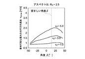
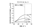
- the maximum value V xmax of the x-direction (horizontal direction) speed V x that does not fall when the flying object 10 lands is obtained as a condition that the flying object 10 set at various angles ⁇ does not fall. It was.
- the z-direction (vertical direction) speed V z when the flying object 10 lands was set to three types of ⁇ 5.0 m / s, ⁇ 3.0 m / s, and ⁇ 1.0 m / s.
- the scaling factor ⁇ of the granular medium is 1.0.
- the flying object 10 is more likely to fall down as the x-direction velocity V x is larger. Therefore, by selecting the angle ⁇ at which the maximum value V xmax of the x-direction velocity V x is increased, the falling of the flying object 10 can be effectively suppressed. That is, in FIGS. 9A to 9D, the angle ⁇ that is the maximum value of V xmax is optimal for suppressing the falling of the flying object 10.
- FIGS. 9A to 9D a desirable angle ⁇ corresponding to each RA based on FIG. 8 obtained using the static model is shown by a broken line. Therefore, in FIGS. 9A to 9D, the closer the position of the broken line is to the position of the maximum value of V xmax , the higher the reliability of the design method using the static model.
- FIGS. 9A to 9D Based on this, referring to FIGS. 9A to 9D, as RA is larger, the position of the broken line tends to be closer to the position where the maximum value of V xmax is obtained. Specifically, in FIGS. 9B to 9D where RA is 2 or more, the position of the broken line is close to the peak position of V xmax . Therefore, it can be seen that when R A is 2 or more, an appropriate angle ⁇ can be obtained even by the design method using the static model.
- the shape of the grounding portion 14 can be variously changed within a range where the above-described effect can be obtained.
- the planar shape of the grounding portion 14 may be other than a circle, and may be, for example, a polygon or an ellipse.
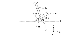
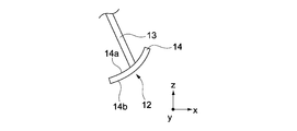
- the grounding portion 14 may have a shape shown in FIGS. 10A to 10C below, for example.
- the upper surface 14a and the lower surface 14b of the grounding part 14 may be a curved surface.
- one of the upper surface 14a and the lower surface 14b may be a flat surface and the other may be a curved surface.
- the flying object 10 is not limited to a space probe.
- the flying object 10 other than the space probe for example, it is necessary to land in a sand dune or desert covered with sand, an area where volcanic ash is accumulated by an eruption of a volcano, an area where earth and sand are accumulated due to a disaster such as an earthquake.
- There are airplanes such as a drone or helicopter.
- the flying object 10 may be a drone having a plurality of propellers 21 and a loading unit 22 on which a load F can be loaded as shown in FIG.
- the loading portion 22 is provided in the main body portion 11, if the center of gravity increases due to the weight of the load F, the flying body 10 easily falls.
- the flying object 10 can land on an inclined surface having a slight gradient as described above. Therefore, the flying object 10 can land on the inclined surface without searching for a flat surface. For this reason, in the flying object 10 as shown in FIG. 11, it is possible to provide supplies, measure data, charge, etc. not only on a flat surface but also on an inclined surface.
- the flying object 10 shown in FIG. 11 is not limited to the above structure.
- the flying object 10 may be configured such that the grounding part 14 can be attached to and detached from the connection part 13. Thereby, in the flying object 10, it is possible to attach the grounding portion 14 when landing on the granular medium, and to remove the grounding portion 14 when landing on other than the granular medium.
- the detachable grounding portion 14 may be configured to be attachable to the bottom and side surfaces of the tip portions of a plurality of legs provided for landing on a ready-made drone.
- the grounding unit 14 can realize the function of the leg structure 12 together with the leg of the drone. For this reason, the grounding part 14 can suppress the fall at the time of landing of a drone.
- the flying object 10 may be an object that flies by being released into space in the sky or on the ground, as well as an airplane that performs self-flight.
- Examples of such a flying object 10 include a measuring device installed by being dropped from an airplane such as a helicopter in a disaster area or a volcanic area where it is difficult for a person to enter.
- the flying object 10 may have a configuration other than the above as necessary.
- the flying body 10 may include a buffer mechanism such as a honeycomb structure or an airbag.
- a buffer mechanism may be provided in the lower part of the main body part 11, and the leg structure 12 may be attached to the lower surface of the buffer mechanism. Further, the buffer mechanism may be provided in the leg structure 12.
Landscapes
- Engineering & Computer Science (AREA)
- Aviation & Aerospace Engineering (AREA)
- Remote Sensing (AREA)
- Mechanical Engineering (AREA)
- Aerodynamic Tests, Hydrodynamic Tests, Wind Tunnels, And Water Tanks (AREA)
- Aiming, Guidance, Guns With A Light Source, Armor, Camouflage, And Targets (AREA)
Abstract
【課題】飛翔体を粒状媒質で覆われた地面に良好に着地させるための技術を提供する。 【解決手段】本発明は、飛翔体の本体部を支持可能な脚部構造体であって、本体部に対向する平面に沿って、平面に直交する軸の周囲に設けられる複数の接地部と、複数の接地部と本体部とを接続する複数の接続部と、を具備し、複数の接地部はそれぞれ、本体部側を向き、平面に対して軸側に傾く第1傾斜面と、本体部側とは反対側を向き、平面に対して軸とは反対側に傾く第2傾斜面と、を有する、脚部構造体を提供する。この構成を備える脚部構造体は、飛翔体が粒状媒質への着地の際に進行方向前方に転倒することを抑制できる。
Description
本発明は、脚部構造体及びこれを用いた飛翔体に関する。
飛翔体が着地する場合に、着地する領域に粒状媒質(granular media)があると、飛翔体の接地部分が粒状媒質に足を取られてしまい、転倒しやすくなる。例えば、月や惑星などの天体には砂やレゴリスなどの粒状媒質で覆われた領域が多く存在する。したがって、天体を探査するための飛翔体である宇宙探査機は、天体に着地する際に転倒しやすい。
宇宙探査機などの飛翔体の着地の際の転倒を防止するためには、飛翔体に加わる衝撃を抑制することが有効である。衝撃を抑制可能な公知の技術としては、ハニカム構造体を利用する技術(例えば、特許文献1、非特許文献1参照)やエアバッグを利用する技術(例えば、特許文献2参照)が知られている。
ハニカム構造体を利用する技術では、ハニカム構造体を塑性変形させることにより、衝撃を吸収する。エアバッグを利用する技術では、エアバッグに収容される気体の圧力上昇に伴う発熱ならびに材料減衰により、衝撃を吸収する。したがって、飛翔体の接地部分である脚部にハニカム構造体を用いることや、エアバッグを用いることにより、飛翔体に加わる衝撃を抑制することができる。
Rogers, W. F., Apollo Experience Report Lunar Module Landing Gear Subsystem, NASA TN D-6850, NASA, (1972), pp.6-21.
ハニカム構造体を利用する技術では、衝撃を吸収可能な方向が特定の方向に限定されるため、飛翔体の着地の角度によっては、適切に衝撃が吸収されない場合がある。また、この技術では、ハニカム構造体が塑性変形するため、飛翔体の着地の度にハニカム構造体を交換する必要がある。
エアバッグを利用する技術では、宇宙探査機が着地の際にエアバッグの弾力によって跳ねてしまう。これを防止するためには、宇宙探査機の着地の瞬間にエアバッグ内の気体を放出させる必要がある。
以上の問題を解決するために、本発明の目的は、飛翔体を粒状媒質で覆われた地面に良好に着地させるための技術を提供することにある。
上記目的を達成するため、本発明は、
飛翔体の本体部を支持可能な脚部構造体であって、
本体部に対向する平面に沿って、平面に直交する軸の周囲に設けられる複数の接地部と、
複数の接地部と本体部とを接続する複数の接続部と、を具備し、
複数の接地部はそれぞれ、
本体部側を向き、平面に対して軸側に傾く第1傾斜面と、
本体部側とは反対側を向き、平面に対して軸とは反対側に傾く第2傾斜面と、を有する
脚部構造体を提供する。
飛翔体の本体部を支持可能な脚部構造体であって、
本体部に対向する平面に沿って、平面に直交する軸の周囲に設けられる複数の接地部と、
複数の接地部と本体部とを接続する複数の接続部と、を具備し、
複数の接地部はそれぞれ、
本体部側を向き、平面に対して軸側に傾く第1傾斜面と、
本体部側とは反対側を向き、平面に対して軸とは反対側に傾く第2傾斜面と、を有する
脚部構造体を提供する。
この構成を備える飛翔体では、飛翔体が粒状媒質に斜め方向に着地する場合に、進行方向前方の接地部が粒状媒質から反力を受けて上昇しようとする。これにより、飛翔体には、進行方向前方に転倒しようとするモーメントとは反対のモーメントが生じる。また、進行方向後方の接地部は、粒状媒質に沈み込むため、粒状媒質によって上方から保持される。このように、この脚部構造体は、飛翔体が粒状媒質への着地の際に進行方向前方に転倒することを抑制できる。
複数の接地部は、軸について相互に対称に設けられていてもよい。
この構成では、様々な着地方向の飛翔体において、着地の際の転倒を抑制する効果が得られる。
この構成では、様々な着地方向の飛翔体において、着地の際の転倒を抑制する効果が得られる。
軸は、飛翔体の重心を通っていてもよい。
この構成では、飛翔体が着地の際に転倒することを更に効果的に抑制できる。
この構成では、飛翔体が着地の際に転倒することを更に効果的に抑制できる。
複数の接地部は、それぞれ平板状に形成されていてもよい。
この構成では、飛翔体における着地の際の転倒を抑制する効果を容易に得ることができる。
この構成では、飛翔体における着地の際の転倒を抑制する効果を容易に得ることができる。
また、本発明は、
本体部と、前記本体部から延び、その先端部が、本体部に対向する平面に沿って、平面に直交する軸の周囲に配置された複数の脚部と、を有するドローンを支持可能な脚部構造体であって、
複数の脚部の先端部にそれぞれ取り付け可能な複数の接地部を具備し、
複数の接地部はそれぞれ、
本体部側を向き、平面に対して軸側に傾く第1傾斜面と、
本体部側とは反対側を向き、平面に対して軸とは反対側に傾く第2傾斜面と、を有する
脚部構造体を提供する。
本体部と、前記本体部から延び、その先端部が、本体部に対向する平面に沿って、平面に直交する軸の周囲に配置された複数の脚部と、を有するドローンを支持可能な脚部構造体であって、
複数の脚部の先端部にそれぞれ取り付け可能な複数の接地部を具備し、
複数の接地部はそれぞれ、
本体部側を向き、平面に対して軸側に傾く第1傾斜面と、
本体部側とは反対側を向き、平面に対して軸とは反対側に傾く第2傾斜面と、を有する
脚部構造体を提供する。
また、本発明は、
本体部と、本体部を支持可能な脚部構造体と、を具備し、
脚部構造体は、
本体部に対向する平面に沿って、平面に直交する軸の周囲に設けられる複数の接地部と、
複数の接地部と本体部とを接続する複数の接続部と、を有し、
複数の接地部はそれぞれ、
本体部側を向き、平面に対して軸側に傾く第1傾斜面と、
本体部側とは反対側を向き、平面に対して軸とは反対側に傾く第2傾斜面と、を有する
飛翔体を提供する。
飛翔体は、粒状媒質で覆われた天体に着地可能な宇宙探査機として構成されていてもよい。
飛翔体は、粒状媒質で覆われた地面に着地可能なドローンとして構成されていてもよい。
本体部と、本体部を支持可能な脚部構造体と、を具備し、
脚部構造体は、
本体部に対向する平面に沿って、平面に直交する軸の周囲に設けられる複数の接地部と、
複数の接地部と本体部とを接続する複数の接続部と、を有し、
複数の接地部はそれぞれ、
本体部側を向き、平面に対して軸側に傾く第1傾斜面と、
本体部側とは反対側を向き、平面に対して軸とは反対側に傾く第2傾斜面と、を有する
飛翔体を提供する。
飛翔体は、粒状媒質で覆われた天体に着地可能な宇宙探査機として構成されていてもよい。
飛翔体は、粒状媒質で覆われた地面に着地可能なドローンとして構成されていてもよい。
以下、図面を参照しながら、本発明の実施形態を説明する。なお、本発明は、以下の実施形態によって限定的に解釈されるものではない。図面には、適宜相互に直交するx軸、y軸、及びz軸が示されている。x軸、y軸、及びz軸は全図において共通である。
1.飛翔体10
図1~5を参照しながら、本発明の一実施形態に係る飛翔体10について説明する。
図1~5を参照しながら、本発明の一実施形態に係る飛翔体10について説明する。
1.1 概略構成
図1は、本実施形態に係る飛翔体10の斜視図である。飛翔体10は、宇宙空間を飛翔し、月や惑星などの天体に着地可能な宇宙探査機として構成される。飛翔体10は、本体部11と、複数の脚部構造体12と、を具備する。複数の脚部構造体12は、本体部11のz軸方向下側に配置されている
図1は、本実施形態に係る飛翔体10の斜視図である。飛翔体10は、宇宙空間を飛翔し、月や惑星などの天体に着地可能な宇宙探査機として構成される。飛翔体10は、本体部11と、複数の脚部構造体12と、を具備する。複数の脚部構造体12は、本体部11のz軸方向下側に配置されている
本体部11は、z軸に平行な中心軸Cを有する円柱状に形成されている。つまり、本体部11は、xy平面に平行な上下面と、z軸方向に延びる円周面である側面と、を有する。なお、本体部11は、円柱状以外であってもよく、任意の立体形状とすることができる。いずれの場合にも、中心軸Cは、飛翔体10の重心を通っていることが好ましい。
本体部11は、様々な機器などを収容している。本体部11に収容される機器としては、例えば、飛翔体10を動作させるための機器や、外部との通信を行うための機器や、天体の探査に必要な機器などが挙げられる。飛翔体10は、本体部11に人を収容しない無人探査機であっても、本体部11に人を収容可能な有人探査機であってもよい。
飛翔体10は、共通の構成を有する複数の脚部構造体12を備えている。各脚部構造体12は、接続部13と、接地部14と、を有する。接続部13は、円形の断面を有する細長い棒状に形成されている。接地部14は、円盤状に形成されたフットパッドとして構成される。脚部構造体12は、本体部11を支え、飛翔体10を自立可能とする。
複数の接続部13は、そのz軸方向上端部において本体部11のz軸方向下面に取り付けられている。より詳細に、複数の接続部13のz軸方向上端部は、本体部11の下面の外周に沿って等間隔に配置されている。また、各接続部13は、中心軸Cから離間するように斜め下方に延びている。
複数の接地部14は、本体部11のz軸方向下方に配置されたxy平面に平行な平面P(図2参照)に沿って、中心軸Cの周囲に配置されている。脚部構造体12は、地面に接地部14を接触させた状態で本体部11を保持する。接地部14は、飛翔体10を安定して支持可能なように、中心軸Cについて対称となるように配置されている。
接地部14は、そのz軸方向上面14aの中心部において接続部13のz軸方向下端部に接続されている。つまり、接続部13は、接地部14を本体部11に接続している。なお、接続部13の構成は、接地部14を本体部11に接続可能であればよく、様々に変更可能である。
接地部14は、xy平面に対して傾けられた状態で配置されている。より詳細に、接地部14のz軸方向上面14aは、中心軸C側に向けて傾いた第1傾斜面として構成される。また、接地部14のz軸方向下面14bは、中心軸Cとは反対側に傾いた第2傾斜面として構成される。
これらにより、脚部構造体12は、中心軸Cについて相互に対称な構成となっている。なお、飛翔体10では、複数の脚部構造体12が設けられていればよく、脚部構造体12の数は4つでなくてもよい。脚部構造体12の数がいずれであっても、脚部構造体12は、中心軸Cについて相互に対称となるように配置されることが好ましい。
飛翔体10は、脚部構造体12の接地部14から粒状媒質(granular media)で覆われた地面に着地可能である。接地部14は、複雑な構成を追加することなく、飛翔体10が粒状媒質で覆われた地面に着地する際における飛翔体10の転倒を抑制可能な構成を実現可能である。以下、接地部14の詳細について説明する。
1.2 接地部14の詳細
図2は、飛翔体10を二次元的に示す模式図である。図2には、本体部11と、x軸方向に相互に対向する2つの脚部構造体12と、が示されている。また、図2には、本体部11のz軸方向下方に配置されたxy平面に平行な平面Pが示されている。上記のとおり、複数の接地部14は、平面Pに沿って設けられている。
図2は、飛翔体10を二次元的に示す模式図である。図2には、本体部11と、x軸方向に相互に対向する2つの脚部構造体12と、が示されている。また、図2には、本体部11のz軸方向下方に配置されたxy平面に平行な平面Pが示されている。上記のとおり、複数の接地部14は、平面Pに沿って設けられている。
接地部14の平面Pに対する角度βは、0°より大きく、90°より小さい。これにより、接地部14は、上記のように、上面14aが中心軸C側に向けて傾き、下面14bが中心軸Cとは反対側に向けて傾いた構成となる。接地部14の角度βの設計方法については後述する。
図3,4は、飛翔体10が粒状媒質で覆われたxy平面に平行に延びる地面に着地する瞬間の状態を示す図である。図3,4には、粒状媒質から各接地部14に加わる反力Wがベクトルとして示されている。なお、図3,4に示される反力Wのベクトルは、おおまかなものであり、正確なものではない。
図3,4では、飛翔体10の粒状媒質への着地方向が異なる。つまり、図3では、飛翔体10の着地方向がz軸方向(垂直方向)下方であり、x軸方向への進行を伴わずに粒状媒質に着地する。一方、図4では、飛翔体10の着地方向が右斜め下方であり、飛翔体10がx軸方向に進行しながら粒状媒質に着地する。
図3に示す状態では、いずれの接地部14にも、粒状媒質からz軸方向上方へのx軸方向やや内向きの反力Wが加わる。したがって、粒状媒質から2つの接地部14に加わる反力Wのx軸方向の成分が相互に打ち消し合うため、飛翔体10全体としては粒状媒質からx軸方向の反力を受けない。
したがって、図3に示す状態では、飛翔体10に、転倒しようとするモーメントが発生しにくい。また、接地部14は、z軸方向下方を向いたx軸方向内側端部から矢印L方向へ粒状媒質中に潜り込むため、粒状媒質中に埋没する。このため、図3に示す状態において、飛翔体10は転倒しにくい。
図4では、x軸方向(進行方向)前方の接地部14が「接地部14(F)」と示され、x軸方向後方の接地部14が「接地部14(B)」と示されている。また、x軸方向前方の接地部14(F)に粒状媒質から加わる反力Wが「反力W(F)」と示され、x軸方向後方の接地部14(B)に粒状媒質から加わる反力Wが「反力W(B)」と示されている。
図4に示す状態では、x軸方向前方の接地部14(F)には、粒状媒質からz軸方向上方及びx軸方向やや後方を向いた斜め向きの反力W(F)が加わる。また、x軸方向後方の接地部14(B)には、粒状媒質からz軸方向上方及びx軸方向後方を向いた斜め向きの反力W(B)が加わる。つまり、接地部14(F),14(B)に加わる反力W(F),W(B)は、いずれもx軸方向後方の成分を持っている。
このため、図4に示す状態では、飛翔体10にx軸方向前方に転倒しようとするモーメントM1が発生する。しかし、x軸方向前方の接地部14(F)が粒状媒質からの反力W(F)によって上昇しようとするため、飛翔体10にモーメントM1とは反対のモーメントM2が発生する。このため、モーメントM1の一部又は全部がモーメントM2によって打ち消される。
また、図4に示す状態では、x軸方向後方の接地部14(B)が、z軸方向下方を向いたx軸方向内側端部から矢印L方向へ粒状媒質中に潜り込むため、粒状媒質によってz軸方向上方から押さえられる。これにより、接地部14(B)は、粒状媒質によって上方への移動が妨げられる。つまり、モーメントM1がモーメントM2よりも大きい場合であっても、飛翔体10のx軸方向前方への転倒が抑制される。
このように、飛翔体10では、x軸方向前方に転倒しようとするモーメントM1の一部又は全部がx軸方向前方の接地部14の作用によるモーメントM2によって打ち消される。更に、飛翔体10では、x軸方向後方の接地部14(B)の粒状媒質中に潜り込む作用によって、飛翔体10のx軸方向前方への転倒が抑制される。
このため、飛翔体10は、x軸方向に進行しながら粒状媒質に着地する場合に転倒しにくい。また、上記で図1を参照しながら説明したように、接地部14は、中心軸Cについて対称に設けられている。このため、飛翔体10は、xy平面に沿った任意の方向に進行しながら粒状媒質に着地する場合にも同様に、転倒を抑制することができる。
図5は、飛翔体10が粒状媒質に着地した後にx軸方向前方に横滑りしている状態を示す図である。図5に示す状態では、接地部14(F),14(B)に加わる反力W(F),W(B)の方向がいずれもx軸方向後方である。このため、飛翔体10には、上記の図4に示す状態と同様に、x軸方向前方に転倒しようとするモーメントM1が発生する。
しかしながら、図5に示す状態でも、図4に示す状態と同様に、x軸方向前方の接地部14(F)が上昇しようとするため、飛翔体10にモーメントM1とは反対のモーメントM2が発生する。したがって、飛翔体10では、x軸方向前方に転倒しようとするモーメントM1の一部又は全部がモーメントM2によって打ち消される。
また、図5に示す状態でも、図4に示す状態と同様に、x軸方向後方の接地部14(B)が、z軸方向下方を向いたx軸方向内側端部から矢印L方向へ粒状媒質中に潜り込むため、飛翔体10のx軸方向前方への転倒が抑制される。このため、飛翔体10は、着地した後に横滑りしている状態でも、転倒しにくい。
更に、図5に示す状態では、粒状媒質中に潜り込んだx軸方向後方の接地部14(B)が、着地後の飛翔体10の横滑りを妨げるブレーキの役割を果たす。これにより、飛翔体10では、粒状媒質への着地後におけるx軸方向への横滑り量が抑制される。したがって、着地後の飛翔体10は、迅速に安定した姿勢を確保可能となる。
以上述べたように、飛翔体10では、接地部14の作用によって、粒状媒質に着地する際の転倒を抑制することができる。また、飛翔体10では、斜めに着地する場合であっても、着地後の横滑りを抑制することができる。このように、飛翔体10は、粒状媒質に覆われた地面に良好に着地することができる。
また、本実施形態に係る飛翔体10では、任意の粒状媒質に対して上記の効果が得られる。このため、飛翔体10は、例えば、未知の特性を有する粒状媒質で覆われた惑星の探査を行う惑星探査機に特に適している。また、飛翔体10は、重力が小さい場合にも上記の効果が得られるため、微小重力天体の探査を行う宇宙探査機にも適している。
なお、以上では、飛翔体10が粒状媒質の表面に水平な姿勢で着地する場合について説明した。しかし、飛翔体10の姿勢が粒状媒質の表面に対して多少傾いていても、上記と同様の効果が得られる。また、飛翔体10は、粒状媒質の表面が多少の勾配のある傾斜面であっても良好に着地可能であるため、特に緊急時の着地に有利である。
また、飛翔体10が着地する粒状媒質には、上記のような作用が得られる範囲において、粒子でない要素が含まれていても構わない。このような要素としては、例えば、金属板や岩盤などの物体や、多数の粒子が寄せ集まって形成された粒子塊や、水などの液体成分などが挙げられる。
2.接地部14の角度βの設計方法
以下では、接地部14の角度βの設計方法の一例について説明する。しかし、接地部14の角度βの設計方法は、下記のものに限定されない。また、接地部14の角度βは、下記の設計方法により得られる数値に限定されず、0°<β<90°の範囲内において適宜決定可能である。
以下では、接地部14の角度βの設計方法の一例について説明する。しかし、接地部14の角度βの設計方法は、下記のものに限定されない。また、接地部14の角度βは、下記の設計方法により得られる数値に限定されず、0°<β<90°の範囲内において適宜決定可能である。
2.1 静的モデルを用いた設計方法
本実施形態では、飛翔体10が粒状媒質で覆われた地面に着地する際のモデルとして、Resistive Force Theory(RFT)を用いる。RFTでは、粒状媒質中の剛体に作用する力は、剛体表面の微小面積に作用する力(すなわち圧力)を剛体の進行方向側の面積で積分することで求まる。
本実施形態では、飛翔体10が粒状媒質で覆われた地面に着地する際のモデルとして、Resistive Force Theory(RFT)を用いる。RFTでは、粒状媒質中の剛体に作用する力は、剛体表面の微小面積に作用する力(すなわち圧力)を剛体の進行方向側の面積で積分することで求まる。
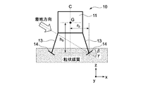
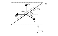
ここで、図6,7に示すような構成を想定する。図6は飛翔体10を示し、図7は接地部14の微小領域14dを拡大して示している。図6,7に示す構成は、飛翔体10が粒状媒質に着地する瞬間が表現された静的モデルである。このモデルでは、接地部14の全体が粒状媒質中に埋まっているものと仮定している。
RFT理論において接地部14の微小領域14dの面積dASに作用する圧力は、圧力関数αx,z(β,γ)で与えられ、αx,zを式(1)に示すように接地部14の面積で積分することで,力fx,zが求まる。

ここで、βsは、微小領域14dの水平面に対する角度である。γsは、ベクトルνで示される微小領域14dの進行方向が水平面となす角度である。dsは、微小領域14dの粒状媒質の表面からの沈下量である。ζは、スケーリングファクタで、粒状媒質の嵩密度や摩擦特性により決定される。
接地部14は平板状であるため、接地部14の水平面に対する角度β、及び接地部14の進行方向が水平面となす角度γは、接地部14全面で一様になる。したがって、式(1)を簡略化することにより、式(2)が得られる。

ここで、rは、接地部14のy方向(紙面方向)の長さである。qは、接地部14の幅である。d0は、接地部14の中心の粒状媒質の表面からの沈下量である。一方、飛翔体10に粒状媒質から作用するトルクτは、反時計回りを正として、式(3)で定義される。

ここで、rb,hbはそれぞれ、飛翔体10の重心Gから接地部14の中心までのx,z方向の距離である。fxF,fzFは、進行方向前方(図6では右側)の接地部14に作用するx,z方向の力である。fxR,fzRは、進行方向後方(図6では左側)の接地部14に作用するx,z方向の力である。
このトルクτは、接地部14の取り付け角度βに依存する。このため、トルクτを最大化する角度βを求めることで、耐転倒性の高い接地部14が設計できる。
rbとhbとの関係をアスペクト比RA(=hb/rb)として表すと、トルクτは式(4)で表される。

ここで、進行方向前方の接地部14の角度βF及び進行方向後方の接地部14の角度βRは、角度βが中心対称であるものとし、つまりβF=-βR=βとする。式(4)の力fに式(2)を代入すると、式(5)が得られる。

RFTでは関数αx,zが三角関数の足し合わせで表現されているため、式(5)のαx,zに代入すると、式(6)のように表現できる。
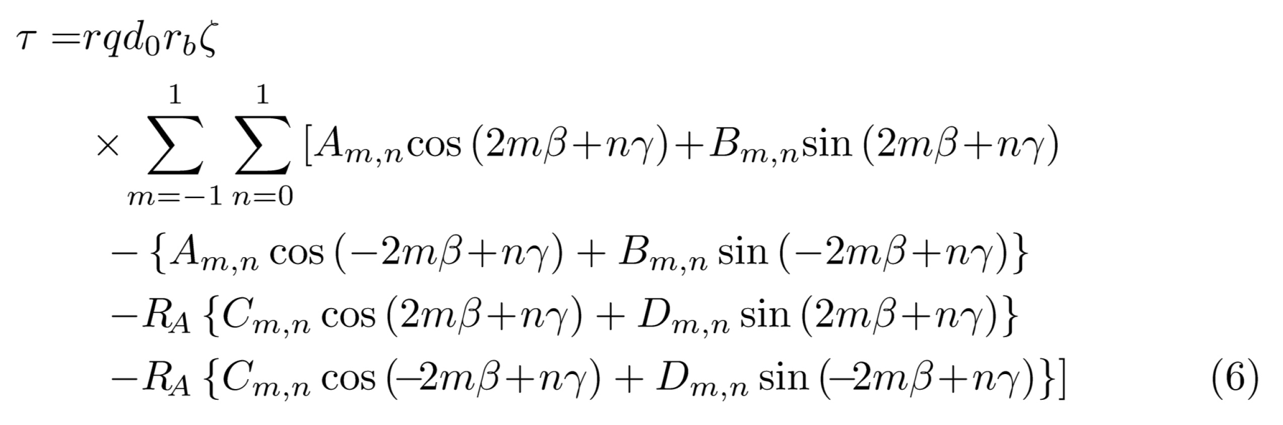
転倒を抑制するトルクを最大化する角度βを求めるためには、式(6)で示される関数の極大値がわかればよい。そこで、式(6)で示される関数の停留点を求めるため、式(6)を角度βで偏微分し、積和公式、合成公式を適用すると、式(7)が得られる。

ここで、Jm,n,Km,n,ηm,n、ξm,nは、以下のとおりである。

ただし、m∈(-1,0,1)、n∈(0,1)である。U(・)は単位ステップ関数である。もし、m=0ならば、式(7)の右辺=0となる。ゆえに、m∈(-1,1)かつn∈(0,1)の場合だけを考えれば良く、式は簡略化される。計算に用いるRFTパラメータは、表1に示す通りである。
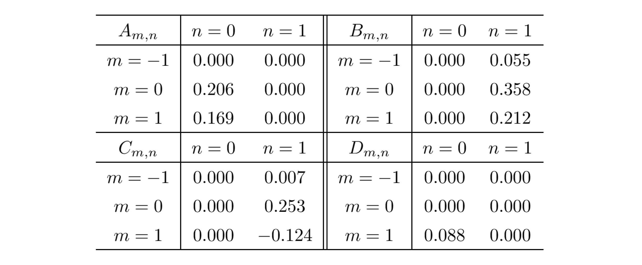
Am,n,Bm,n,Cm,n,Dm,nを式(8),(9)へ代入すると、値が0のパラメータもあるため、更に簡略化され、下記のようになる。
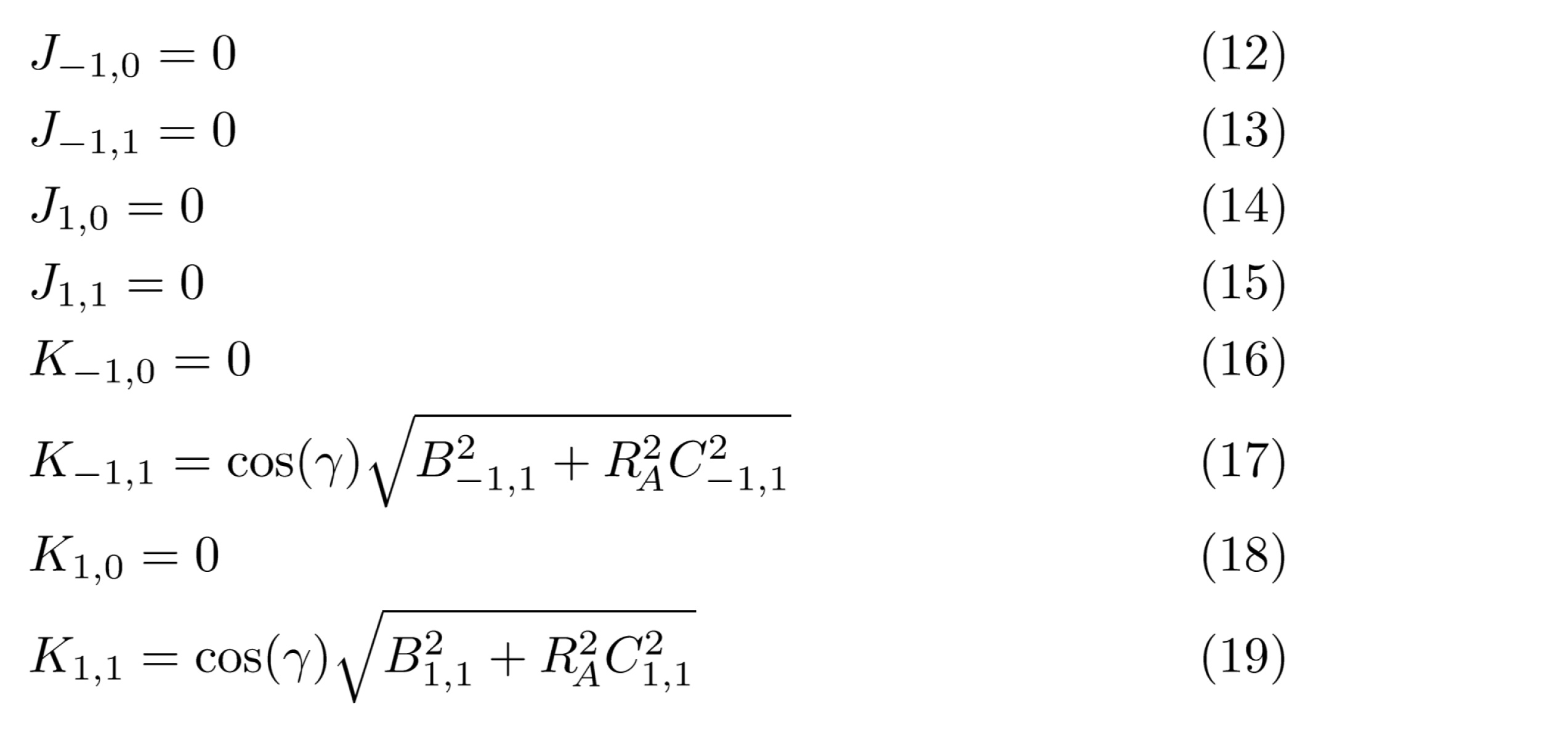
この結果より、式(7)は次式のように表され、転倒を抑制するトルクが最大になる角度βは式(20)を解くことで求まる。

式(20)を解くと、∂τ/∂βが停留する角度βは、三角関数の位相も考慮すると、機体水平速度が+x方向の場合に、転倒を抑制するトルクを最大化する角度β、すなわち、転倒に寄与するトルクの絶対値を最小化する角度βは、式(21)で示すようになる。

ただし、ψは、式(22)で表される。

なおかつ、K-1,1,K1,1はγを含むが、約分して消去できる。
ここで着目すべきは、ξ及びψには、式(11),(22)に示す通り、着地方向の角度γが含まれていない点である。これが意味するのは。転倒を抑制するのに適した角度βは、RFTパラメータAm,n,Bm,n,Cm,n,Dm,nとアスペクト比RAのみで決定されるということである。
したがって、この静的モデルを用いた設計方法では、様々な着地条件下でも共通の指針で接地部14における角度βを決定することが可能である。当然ながら、両側の接地部14の取り付け角度βは中心軸Cについて対称であるため、飛翔体10が-x方向の水平方向速度で着地する場合にも同様に転倒を抑制する効果が得られる。
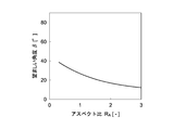
図8は、式(21)から求められる、各アスペクト比RAにおける望ましい角度βを示すグラフである。つまり、以上のような静的モデルを用いた設計方法では、飛翔体10の着地する際の転倒を抑制するために、飛翔体10におけるアスペクト比RAに応じた角度βを選択することができる。
2.1 動的モデルを用いた検証
接地部14の最適な角度βをより正確に得るためには、上記のような静的モデルではなく、動的モデルを用いることが好ましい。しかし、動的モデルを用いると、計算が非常に煩雑になる。したがって、静的モデルを用いることにより、接地部14の角度βを簡便に設計可能となる。
接地部14の最適な角度βをより正確に得るためには、上記のような静的モデルではなく、動的モデルを用いることが好ましい。しかし、動的モデルを用いると、計算が非常に煩雑になる。したがって、静的モデルを用いることにより、接地部14の角度βを簡便に設計可能となる。
そこで、以下では、上記の静的モデルを用いた設計方法による図8に示す結果の信頼性について、動的モデルを用いたシミュレーションによって検証した結果について説明する。
具体的に、様々な角度βに設定した飛翔体10が着地する際に転倒しない条件として、飛翔体10が着地する際に転倒しないx方向(水平方向)速度Vxの最大値Vxmaxを求めた。飛翔体10が着地する際のz方向(垂直方向)速度Vzは、-5.0m/s、-3.0m/s、-1.0m/sの3通りとした。また、粒状媒質のスケーリングファクタζは、1.0とした。
図9Aは、RA=1.5とした場合の結果を示すグラフである。図9Bは、RA=2とした場合の結果を示すグラフである。図9Cは、RA=2.5とした場合の結果を示すグラフである。図9Dは、RA=3とした場合の結果を示すグラフである。図9A~9Dでは、横軸を角度βとし、縦軸をVxmaxとしている。
なお、図9A~9Dにおいて、角度βがゼロのときは接地部14が平面Pに平行であり、角度βがマイナスのときは接地部14が図6に示す状態とは反対側に傾いているものとしている。
飛翔体10は、x方向速度Vxが大きいほど、転倒しやすくなる。したがって、x方向速度Vxの最大値Vxmaxが大きくなる角度βを選択することにより、飛翔体10の転倒を効果的に抑制することができる。つまり、図9A~9Dでは、Vxmaxの最大値となる角度βが、飛翔体10の転倒を抑制するために最適である。
また、図9A~9Dには、静的モデルを用いて得られた図8に基づく、それぞれのRAに応じた望ましい角度βが破線で示されている。したがって、図9A~9Dにおいて、この破線の位置がVxmaxの最大値の位置に近いほど、静的モデルを用いた設計方法の信頼性が高いということになる。
これを踏まえて、図9A~9Dを参照すると、RAが大きいほど、破線の位置が、Vxmaxの最大値となる位置に近くなる傾向が見られる。具体的に、RAが2以上である図9B~9Dでは、破線の位置がVxmaxのピークの位置に近くなっている。したがって、RAが2以上の場合に、静的モデルを用いた設計方法でも適切な角度βが得られることがわかる。
更に、RAが3である図9Dでは、破線の位置がVxmaxのピークの位置がほぼ一致している。したがって、RAが3の場合には、静的モデルを用いた設計方法でも、動的モデルを用いた設計方法と遜色のない最適な角度βが得られることがわかる。このように、角度βを得るために静的モデルによる設計方法を利用可能な条件があることがわかった。
3.その他の実施形態
以上、本発明の実施形態について説明したが、本発明は上述の実施形態にのみ限定されるものではなく、例えば以下のように、種々変更を加え得ることは勿論である。
以上、本発明の実施形態について説明したが、本発明は上述の実施形態にのみ限定されるものではなく、例えば以下のように、種々変更を加え得ることは勿論である。
3.1 接地部14の形状
接地部14の形状は、上記の効果が得られる範囲において様々に変更可能である。例えば、接地部14の平面形状は、円形以外であってもよく、例えば、多角形や楕円形などであってもよい。また、接地部14は、例えば、以下の図10A~10Cに示す形状であってもよい。
接地部14の形状は、上記の効果が得られる範囲において様々に変更可能である。例えば、接地部14の平面形状は、円形以外であってもよく、例えば、多角形や楕円形などであってもよい。また、接地部14は、例えば、以下の図10A~10Cに示す形状であってもよい。
つまり、図10Aに示すように、接地部14では、上面14aの角度β1と、下面14bの角度β2と、が相互に異なっていてもよい。また、図10Bに示すように、接地部14の上面14a及び下面14bが曲面であってもよい。更に、図10Cに示すように、上面14a及び下面14bの一方が平面で他方が曲面であってもよい。
3.2 飛翔体10の他の実施形態
飛翔体10は、宇宙探査機に限定されない。宇宙探査機以外の飛翔体10としては、例えば、砂に覆われた砂丘や砂漠、火山の噴火によって火山灰が堆積した地域や、地震などの災害などで土砂が堆積した地域などに着地する必要があるドローンやヘリコプターなどの飛行機が挙げられる。
飛翔体10は、宇宙探査機に限定されない。宇宙探査機以外の飛翔体10としては、例えば、砂に覆われた砂丘や砂漠、火山の噴火によって火山灰が堆積した地域や、地震などの災害などで土砂が堆積した地域などに着地する必要があるドローンやヘリコプターなどの飛行機が挙げられる。
一例として、飛翔体10は、図11に示すような、複数のプロペラ21や、荷物Fを積載可能な積載部22を有するドローンであってもよい。このような飛翔体10では、積載部22が本体部11に設けられるため、荷物Fの重量によって重心が高くなると転倒しやすくなる。
図11に示すような飛翔体10では、着地の際に転倒すると、プロペラ21と地面との接触などにより全損したり、破損したプロペラ21の破片が飛散したりすることにより大きな被害が発生する場合がある。しかしながら、このような飛翔体10においても、接地部14の作用によって転倒が抑制されるため、上記の被害を未然に防ぐことができる。
また、飛翔体10は、上記のとおり、多少の勾配のある傾斜面にも良好に着地可能である。したがって、この飛翔体10では、平坦面を探し出すことなく、傾斜面に着地可能である。このため、図11に示すような飛翔体10では、平坦面のみならず傾斜面においても、物資の提供や、データの計測や、充電などを行うことが可能である。
なお、図11に示す飛翔体10は、上記の構造に限定されない。例えば、飛翔体10は、接地部14が接続部13に着脱可能に構成されていてもよい。これにより、飛翔体10では、粒状媒質上に着地する場合に接地部14を装着し、粒状媒質以外に着地する場合に接地部14を取り外すことが可能となる。
また、着脱可能な接地部14は、既製のドローンに着地用に備えられた複数の脚部の先端部の底面や側面にそれぞれ装着可能に構成されていてもよい。接地部14は、ドローンの脚部とともに脚部構造体12の機能を実現することができる。このため、接地部14は、ドローンの着地時の転倒を抑制することができる。
更に、飛翔体10は、自力飛行を行う飛行機のみでなく、上空や地上において空間に放たれることにより飛翔する物体であってもよい。このような飛翔体10としては、人が立ち入ることの困難な災害地や火山地域などに、ヘリコプターなどの飛行機から投下されることにより設置される計測機器などが挙げられる。
3.3 追加の構成
飛翔体10は、必要に応じて、上記以外の構成を備えていてもよい。例えば、飛翔体10は、ハニカム構造体やエアバッグなどの緩衝機構を備えていてもよい。一例として、緩衝機構が本体部11の下部に設けられ、脚部構造体12が緩衝機構の下面に取り付けられていてもよい。更に、緩衝機構は、脚部構造体12に設けられていてもよい。
飛翔体10は、必要に応じて、上記以外の構成を備えていてもよい。例えば、飛翔体10は、ハニカム構造体やエアバッグなどの緩衝機構を備えていてもよい。一例として、緩衝機構が本体部11の下部に設けられ、脚部構造体12が緩衝機構の下面に取り付けられていてもよい。更に、緩衝機構は、脚部構造体12に設けられていてもよい。
10…飛翔体
11…本体部
12…脚部構造体
13…接続部
14…接地部
14a…上面
14b…下面
C…中心軸
P…平面
M1,M2…モーメント
W…反力
β…角度
11…本体部
12…脚部構造体
13…接続部
14…接地部
14a…上面
14b…下面
C…中心軸
P…平面
M1,M2…モーメント
W…反力
β…角度
Claims (8)
- 飛翔体の本体部を支持可能な脚部構造体であって、
前記本体部に対向する平面に沿って、前記平面に直交する軸の周囲に設けられる複数の接地部と、
前記複数の接地部と前記本体部とを接続する複数の接続部と、を具備し、
前記複数の接地部はそれぞれ、
前記本体部側を向き、前記平面に対して前記軸側に傾く第1傾斜面と、
前記本体部側とは反対側を向き、前記平面に対して前記軸とは反対側に傾く第2傾斜面と、を有する
脚部構造体。 - 請求項1に記載の脚部構造体であって、
前記複数の接地部は、前記軸について相互に対称に設けられる
脚部構造体。 - 請求項1又は2に記載の脚部構造体であって、
前記軸は、前記飛翔体の重心を通る
脚部構造体。 - 請求項1から3のいずれか1項に記載の脚部構造体であって、
前記複数の接地部は、それぞれ平板状に形成されている
脚部構造体。 - 本体部と、前記本体部から延び、その先端部が、前記本体部に対向する平面に沿って、前記平面に直交する軸の周囲に配置された複数の脚部と、を有するドローンを支持可能な脚部構造体であって、
前記複数の脚部の前記先端部にそれぞれ取り付け可能な複数の接地部を具備し、
前記複数の接地部はそれぞれ、
前記本体部側を向き、前記平面に対して前記軸側に傾く第1傾斜面と、
前記本体部側とは反対側を向き、前記平面に対して前記軸とは反対側に傾く第2傾斜面と、を有する
脚部構造体。 - 本体部と、前記本体部を支持可能な脚部構造体と、を具備し、
前記脚部構造体は、
前記本体部に対向する平面に沿って、前記平面に直交する軸の周囲に設けられる複数の接地部と、
前記複数の接地部と前記本体部とを接続する複数の接続部と、を有し、
前記複数の接地部はそれぞれ、
前記本体部側を向き、前記平面に対して前記軸側に傾く第1傾斜面と、
前記本体部側とは反対側を向き、前記平面に対して前記軸とは反対側に傾く第2傾斜面と、を有する
飛翔体。 - 請求項6に記載の飛翔体であって、
粒状媒質で覆われた天体に着地可能な宇宙探査機として構成される
飛翔体。 - 請求項6に記載の飛翔体であって、
粒状媒質で覆われた地面に着地可能なドローンとして構成される
飛翔体。
Priority Applications (1)
| Application Number | Priority Date | Filing Date | Title |
|---|---|---|---|
| JP2018537409A JP6590353B2 (ja) | 2016-09-02 | 2017-08-31 | 脚部構造体及びこれを用いた飛翔体 |
Applications Claiming Priority (2)
| Application Number | Priority Date | Filing Date | Title |
|---|---|---|---|
| JP2016171722 | 2016-09-02 | ||
| JP2016-171722 | 2016-09-02 |
Publications (1)
| Publication Number | Publication Date |
|---|---|
| WO2018043665A1 true WO2018043665A1 (ja) | 2018-03-08 |
Family
ID=61301084
Family Applications (1)
| Application Number | Title | Priority Date | Filing Date |
|---|---|---|---|
| PCT/JP2017/031429 Ceased WO2018043665A1 (ja) | 2016-09-02 | 2017-08-31 | 脚部構造体及びこれを用いた飛翔体 |
Country Status (2)
| Country | Link |
|---|---|
| JP (1) | JP6590353B2 (ja) |
| WO (1) | WO2018043665A1 (ja) |
Cited By (1)
| Publication number | Priority date | Publication date | Assignee | Title |
|---|---|---|---|---|
| US20220212796A1 (en) * | 2019-05-08 | 2022-07-07 | Bayer Aktiengesellschaft | Unmanned aerial vehicle |
Citations (3)
| Publication number | Priority date | Publication date | Assignee | Title |
|---|---|---|---|---|
| JP2001322640A (ja) * | 2000-05-16 | 2001-11-20 | Sanko Co Ltd | 合成樹脂製パレット |
| JP2011136686A (ja) * | 2010-01-04 | 2011-07-14 | Astrium Gmbh | 宇宙飛行体用着陸装置 |
| JP2016107843A (ja) * | 2014-12-08 | 2016-06-20 | Jfeスチール株式会社 | マルチコプタを用いた3次元形状計測方法および装置 |
Family Cites Families (1)
| Publication number | Priority date | Publication date | Assignee | Title |
|---|---|---|---|---|
| JP2001322600A (ja) * | 2000-05-16 | 2001-11-20 | Sumitomo Heavy Ind Ltd | 惑星探査機 |
-
2017
- 2017-08-31 JP JP2018537409A patent/JP6590353B2/ja active Active
- 2017-08-31 WO PCT/JP2017/031429 patent/WO2018043665A1/ja not_active Ceased
Patent Citations (3)
| Publication number | Priority date | Publication date | Assignee | Title |
|---|---|---|---|---|
| JP2001322640A (ja) * | 2000-05-16 | 2001-11-20 | Sanko Co Ltd | 合成樹脂製パレット |
| JP2011136686A (ja) * | 2010-01-04 | 2011-07-14 | Astrium Gmbh | 宇宙飛行体用着陸装置 |
| JP2016107843A (ja) * | 2014-12-08 | 2016-06-20 | Jfeスチール株式会社 | マルチコプタを用いた3次元形状計測方法および装置 |
Cited By (3)
| Publication number | Priority date | Publication date | Assignee | Title |
|---|---|---|---|---|
| US20220212796A1 (en) * | 2019-05-08 | 2022-07-07 | Bayer Aktiengesellschaft | Unmanned aerial vehicle |
| JP2022531702A (ja) * | 2019-05-08 | 2022-07-08 | バイエル・アクチエンゲゼルシヤフト | 無人航空機 |
| JP7649255B2 (ja) | 2019-05-08 | 2025-03-19 | バイエル・アクチエンゲゼルシヤフト | 無人航空機 |
Also Published As
| Publication number | Publication date |
|---|---|
| JP6590353B2 (ja) | 2019-10-16 |
| JPWO2018043665A1 (ja) | 2019-03-22 |
Similar Documents
| Publication | Publication Date | Title |
|---|---|---|
| US11242162B2 (en) | Methods and apparatus for in-situ measurements of atmospheric density | |
| Morris et al. | Approach for modeling rocket plume impingement and dust dispersal on the moon | |
| Inaba et al. | Dusty vortices in protoplanetary disks | |
| Cassell et al. | ADEPT, A Mechanically Deployable Re-Entry Vehicle System, Enabling Interplanetary CubeSat and Small Satellite Missions | |
| Morris et al. | Lunar dust transport resulting from single-and four-engine plume impingement | |
| Hockman et al. | Experimental methods for mobility and surface operations of microgravity robots | |
| JP6590353B2 (ja) | 脚部構造体及びこれを用いた飛翔体 | |
| Wang et al. | Simulating space capsule water landing with explicit finite element method | |
| Morris | Simulation of rocket plume impingement and dust dispersal on the lunar surface | |
| Maeda et al. | Design of landing-gear footpad based on resistive force generated by celestial soil | |
| Quillen et al. | A light-weight vibrational motor powered recoil robot that hops rapidly across granular media | |
| Cole et al. | The challenges of designing a lightweight spacecraft structure for landing on the lunar surface | |
| Fasanella | Multiterrain earth landing systems applicable for manned space capsules | |
| Asundi et al. | Genesis of a multi-function drag measurement system to facilitate atmosphere modeling and space debris mitigation | |
| Lu et al. | Pitching angle on space capsule water landing using smooth particle hydrodynamic method | |
| Genta et al. | Preliminary analysis of the deformed shape of an inflated light sail | |
| Karagiozis et al. | Computational fluid-structure interaction methods for simulation of inflatable aerodynamic decelerators | |
| US20260116581A1 (en) | Utilization of swarms for sample return and multipoint observation using inflatables | |
| Adams | Phoenix Mars scout landing risk assessment | |
| Lasky-Headrick et al. | Mercurial Array of Probing Seismographs | |
| Kramer et al. | Fluid-structure interaction simulation of an inflatable aerodynamic tension-cone decelerator | |
| Lorenz et al. | Parachute deployment on Venus: Recovery of “Lost” Pioneer Venus large probe entry accelerometer data | |
| Linggi | Analysis of a Wedge Core Hypersonic Waverider for Use in Sub-Orbital Aerodynamic Re-Entry Experiment | |
| Kruijff | Concept selection and design of the inherently safe re-entry capsule for YES2 | |
| Wright et al. | Current investments in the NASA entry systems modeling project |
Legal Events
| Date | Code | Title | Description |
|---|---|---|---|
| 121 | Ep: the epo has been informed by wipo that ep was designated in this application |
Ref document number: 17846669 Country of ref document: EP Kind code of ref document: A1 |
|
| ENP | Entry into the national phase |
Ref document number: 2018537409 Country of ref document: JP Kind code of ref document: A |
|
| NENP | Non-entry into the national phase |
Ref country code: DE |
|
| 122 | Ep: pct application non-entry in european phase |
Ref document number: 17846669 Country of ref document: EP Kind code of ref document: A1 |