WO2018042779A1 - Optical connector assembly - Google Patents
Optical connector assembly Download PDFInfo
- Publication number
- WO2018042779A1 WO2018042779A1 PCT/JP2017/019389 JP2017019389W WO2018042779A1 WO 2018042779 A1 WO2018042779 A1 WO 2018042779A1 JP 2017019389 W JP2017019389 W JP 2017019389W WO 2018042779 A1 WO2018042779 A1 WO 2018042779A1
- Authority
- WO
- WIPO (PCT)
- Prior art keywords
- plug
- receptacle
- optical
- ferrule
- housing
- Prior art date
Links
Images


Classifications
-
- G—PHYSICS
- G02—OPTICS
- G02B—OPTICAL ELEMENTS, SYSTEMS OR APPARATUS
- G02B6/00—Light guides; Structural details of arrangements comprising light guides and other optical elements, e.g. couplings
- G02B6/24—Coupling light guides
- G02B6/36—Mechanical coupling means
-
- G—PHYSICS
- G02—OPTICS
- G02B—OPTICAL ELEMENTS, SYSTEMS OR APPARATUS
- G02B6/00—Light guides; Structural details of arrangements comprising light guides and other optical elements, e.g. couplings
- G02B6/24—Coupling light guides
- G02B6/42—Coupling light guides with opto-electronic elements
Definitions
- the present invention relates to an optical connector assembly, and more particularly, to an optical connector assembly for connecting an optical module installed inside a housing and an optical cable arranged outside the housing.
- the optical module is mounted on the circuit board, for example, together with the circuit board into the housing.
- the optical module is attached to the end of the optical cable to facilitate the installation work.
- the plug is removed from a receptacle attached to the wall of the housing.
- the optical module must be installed inside the housing together with the circuit board in a state where the optical module cannot be aligned with the plug, and is generated between the optical connector built in the plug and the adapter of the optical module. It is necessary to absorb misalignment.
- the optical connector 4 attached to the tip of the optical fiber 3 included in the optical cable 2 is in a three-dimensional direction with respect to the outer member 5.
- Floating structure that can be moved is adopted.
- An optical module installed in the housing 6 by moving the optical connector 4 relative to the outer member 5 when the plug 1 with a built-in connector is fitted into a receptacle 7 attached to the wall of the housing 6. 8 is absorbed, and the optical fiber 3 of the optical cable 2 is connected to the optical module 8.
- An object of the present invention is to provide an optical connector assembly that can optically connect an optical connector built in a plug and an optical module.
- An optical connector assembly is an optical connector assembly for connecting an optical module installed inside a housing and an optical cable arranged outside the housing, and is attached to a wall portion of the housing. And a plug that has an optical connector connected to the end of the optical cable and that fits into the receptacle along the fitting direction.
- the receptacle projects into the housing and is inserted into the adapter of the optical module.
- a positioning guide portion for positioning the receptacle with respect to the optical module is provided, and the optical connector and the optical module are optically connected by fitting the plug into the receptacle.
- the positioning guide part is a protrusion that is formed integrally with the receptacle and extends toward the inside of the housing.
- the optical module has a shape suitable for the adapter, and can be configured to be inserted into the adapter of the optical module together with the positioning guide portion.
- an attachment part that can move in a direction orthogonal to the fitting direction is fitted into the receptacle at a place where the receptacle is attached to the wall portion.
- the receptacle has a relay connector for optically connecting between the optical connector and the optical module when the plug is fitted to the receptacle, and the optical module adapter is connected to the optical module side end of the relay connector.
- the relay guide has a first ferrule disposed at the end on the optical module side, a second ferrule disposed at the end on the plug side, and first ends at the first end.
- An optical fiber held by the ferrule and the second ferrule may be included, and the first ferrule may be optically connected to the optical module, and the second ferrule may be optically connected to the optical connector.
- the first ferrule is preferably held in the relay connector so as to be movable in the fitting direction, and the relay connector further includes a first spring that presses the first ferrule toward the inside of the housing along the fitting direction.
- the optical connector further includes a plug-side ferrule that is held in the optical connector so as to be movable in the fitting direction, and a plug-side spring that presses the plug-side ferrule toward the receptacle along the fitting direction. Can be configured to be held in the relay connector in a fixed position and optically connected to the plug-side ferrule.
- the optical connector has a plug-side ferrule held in the optical connector in a fixed position
- the second ferrule is held in the relay connector so as to be movable in the fitting direction
- the relay connector is
- the second ferrule may further include a second spring that presses the second ferrule toward the outside of the housing along the fitting direction, and the second ferrule may be configured to be optically connected to the plug-side ferrule.
- the first spring and the second spring may be composed of one common spring common to the first ferrule and the second ferrule. It is preferable to have a plug lock mechanism for restricting the fitting state between the plug and the receptacle.
- the positioning guide part has a shape corresponding to at least a part of the adapter in accordance with a predetermined standard.
- the receptacle attached to the wall portion of the housing has the positioning guide portion that positions the receptacle with respect to the optical module by protruding into the housing and being inserted into the adapter of the optical module. Therefore, even if the optical module is installed inside the housing without fitting the plug into the receptacle, it is possible to optically connect the optical connector of the plug and the optical module while suppressing variation in transmission loss. Become.
- FIG. 3 is a cross-sectional view taken along line AA in FIG.
- FIG. 5 is a cross-sectional view taken along the line BB in FIG. It is a perspective view which shows a mode that the receptacle of the optical connector assembly which concerns on Embodiment 1 is applied to the wall part of a housing
- FIG. 3 is a plan view showing a state in which the receptacle of the optical connector assembly according to Embodiment 1 is applied to the wall portion of the housing. It is a perspective view which shows the adapter of an optical module.
- FIG. 1 It is a front view which shows the adapter of an optical module. It is a top view which shows the state which inserted the positioning guide part of the receptacle of the optical connector assembly which concerns on Embodiment 1 in the adapter of an optical module. It is CC sectional view taken on the line of FIG. It is a perspective view which shows a mode that the receptacle of the optical connector assembly which concerns on Embodiment 1 is attached to the wall part of a housing
- FIG. 3 is a partially enlarged plan view showing a main part of the optical connector assembly according to Embodiment 1 in a state in which the plug is fitted to the receptacle. It is the DD sectional view taken on the line of FIG. It is a perspective view which shows the optical connector assembly which concerns on Embodiment 1 of the state which fitted the plug to the receptacle. It is a perspective view which shows the optical connector assembly which concerns on Embodiment 2 before fitting a plug to a receptacle.
- the receptacle used for the optical connector assembly which concerns on Embodiment 2 is shown, (A) is the perspective view seen from diagonally forward, (B) is the perspective view seen from diagonally back, (C) is a front view, (D ) Is a rear view, (E) is a side view, and (F) is a plan view. It is the EE sectional view taken on the line of FIG.
- the plug used for the optical connector assembly which concerns on Embodiment 2 is shown, (A) is the perspective view seen from diagonally forward, (B) is the perspective view seen from diagonally back, (C) is a side view, (D ) Is a plan view, and (E) is a front view.
- FIG. 21 is a sectional view taken along line FF in FIG. It is a perspective view which shows a mode that the receptacle of the optical connector assembly which concerns on Embodiment 2 is attached to the wall part of a housing
- FIG. 6 is a side view showing a receptacle of an optical connector assembly according to a second embodiment and an optical module installed inside a housing. It is a perspective view which shows the optical connector assembly which concerns on Embodiment 2 of the state which fitted the plug to the receptacle. It is side surface sectional drawing which shows the optical connector assembly which concerns on Embodiment 2 of the state which fitted the plug to the receptacle. It is a perspective view which shows the optical connector assembly which concerns on Embodiment 3 before fitting a plug to a receptacle.
- FIG. 10 is a side cross-sectional view showing a receptacle used in the optical connector assembly according to Embodiment 3.
- FIG. 10 is a side cross-sectional view showing a receptacle used in the optical connector assembly according to Embodiment 3.
- FIG. 6 is a side cross-sectional view showing a plug used in the optical connector assembly according to Embodiment 3. It is side surface sectional drawing which shows the optical connector assembly which concerns on Embodiment 3 of the state which fitted the plug to the receptacle. It is a perspective view which shows the optical connector assembly which concerns on Embodiment 4 before fitting a plug to a receptacle.
- FIG. 10 is a side cross-sectional view showing a receptacle used in the optical connector assembly according to Embodiment 4. It is side surface sectional drawing which shows the optical connector assembly which concerns on Embodiment 4 of the state which fitted the plug to the receptacle. It is side surface sectional drawing which shows the conventional optical connector assembly.
- FIG. 1 shows a configuration of an optical connector assembly according to Embodiment 1 of the present invention.
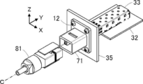
- the optical connector assembly includes a receptacle 11 and a plug 21. By moving the plug 21 in the fitting direction along the fitting axis C, the receptacle 11 and the plug 21 are fitted.
- FIG. 1 shows a state before fitting, in which the receptacle 11 and the plug 21 are spaced apart from each other.
- the receptacle 11 is attached to a wall portion of a casing 31 of a communication device or the like using two fixing screws 12, and an optical module 33 mounted on a circuit board 32 is provided inside the casing 31. Is installed.
- the plug 21 has an optical connector 22 connected to the tip of an optical cable 41 disposed outside the housing 31.
- the direction from the plug 21 toward the receptacle 11 along the fitting axis C is the + Y direction
- the plane on which the circuit board 32 on which the optical module 33 is mounted extends is the XY plane
- the receptacle 11 is attached.
- a plane in which the wall portion of the casing 31 extends is called an XZ plane.
- the receptacle 11 includes a flat plate-shaped fixing portion 13 extending along the XZ plane, and a tube protruding in the ⁇ Y direction from the ⁇ Y direction side surface of the fixing portion 13. And two protrusions 15 protruding in the + Y direction parallel to each other from the + Y direction side surface of the fixed portion 13.
- the fixing portion 13 is for fixing the receptacle 11 to the wall portion of the casing 31, and a thin plate portion 13A having a thickness smaller than that of the periphery is formed at the + X direction end portion and the ⁇ X direction end portion, respectively.
- a through hole (not shown) that penetrates in the Y direction is formed in the thin plate portion 13A, and a rivet (attachment part) 13B is loosely fitted into the through hole so as to be movable in the XZ plane.
- the receptacle 11 is attached so as to be movable in a direction orthogonal to the fitting direction by screwing the fixing screw 12 through the attachment hole 13C formed in the rivet 13B into the wall portion of the housing 31.
- the cylindrical portion 14 is inserted with the plug 21 at the time of fitting, has a cross-sectional shape corresponding to the outer peripheral portion of the plug 21, and as shown in FIGS. 2C and 2D, the cylindrical portion 14
- An opening 13 ⁇ / b> D through which the optical connector 22 of the plug 21 penetrates is formed in the fixing portion 13 positioned inside 14.
- the two protruding portions 15 protrude from the two edge portions of the opening 13 ⁇ / b> D in the + Y direction, and the receptacle 11 with respect to the optical module 33 installed inside the housing 31.
- a positioning guide portion for positioning is configured. Further, as shown in FIGS.
- a waterproofing member 17 having a rectangular frame shape surrounding the opening 13D is attached.
- the structure of the plug 21 is shown in FIGS.
- the plug 21 has a plug housing 23 slidably connected to the optical connector 22 in the ⁇ Y direction along the fitting direction.
- the optical connector 22 includes a plug-side ferrule 24 that holds the tip of the optical fiber included in the optical cable 41, and a sleeve 25 that holds the plug-side ferrule 24 so as to be movable in the Y direction.
- two concave portions 25 ⁇ / b> A into which the two protruding portions 15 constituting the positioning guide portion of the receptacle 11 are fitted are formed on the outer peripheral portion of the sleeve 25 when viewed from the fitting direction. Yes.
- the plug 21 includes a lock mechanism having a structure described in Japanese Patent Application Laid-Open No. 2015-185293 filed by the present applicant. That is, as shown in FIGS. 4A to 4D, a cantilever-shaped latch piece that protrudes in the + Z direction toward the ⁇ Y direction on the surface of the sleeve 25 of the optical connector 22 on the + Z direction side. 26 is formed, and the arm portion 27 protrudes in the + Y direction from the end portion of the plug housing 23 in the + Y direction, and a pressing portion 28 is formed at the tip of the arm portion 27. It is located so as to overlap the + Z direction side of the end.
- the plug housing 23 is pushed in the + Y direction with respect to the optical connector 22 by a spring (not shown), and the plug housing 23 is moved to the ⁇ Y direction side with respect to the optical connector 22 against the elastic force of the spring.
- the pressing portion 28 pushes the latch piece 26 in the ⁇ Z direction, whereby the ⁇ Y direction end of the latch piece 26 is elastically displaced in the ⁇ Z direction.
- a waterproof member 29 surrounding the plug housing 23 is attached to the outer periphery of the plug housing 23.
- the optical module 33 is installed inside the housing 31 in a state of being mounted on the circuit board 32.
- the optical module 33 has an adapter 34 at the end, and the adapter 34 is disposed at a position close to the wall portion of the housing 31.
- An opening 31A for passing the two protruding portions 15 of the receptacle 11 and the optical connector 22 of the plug 21 and an opening 31A in the X direction are provided on the wall of the housing 31 close to the adapter 34 of the optical module 33.
- Two screw holes 31 ⁇ / b> B are formed on both sides.
- the opening 31 ⁇ / b> A is sized to enter the inside of the frame-shaped waterproof member 17 of the receptacle 11 when the receptacle 11 is attached to the wall of the housing 31, and the two protruding shapes of the receptacle 11. It is assumed that the size of the portion 15 and the tip of the optical connector 22 of the plug 21 is larger than the combined size.
- the adapter 34 of the optical module 33 is, for example, an adapter standardized to IEC 61754-20, and has a shape opened toward the ⁇ Y direction and the + Z direction, as shown in FIGS. 8 and 9, and + Z A direction-facing opening 34A and a pair of overhanging parts 34B arranged adjacent to the ⁇ Y direction side of the opening 34A and facing each other in the X direction.
- the opening 31 ⁇ / b> A formed in the wall portion of the housing 31 is formed to be larger than the combined size of the two protruding portions 15 of the receptacle 11 and the tip of the optical connector 22 of the plug 21.
- the receptacle 11 can be positioned while the receptacle 11 is moved in the XZ plane in a state where the two protruding portions 15 are passed through the opening 31A.
- the fixing screws 12 are respectively passed through the attachment holes 13 ⁇ / b> C of the two rivets 13 ⁇ / b> B of the receptacle 11 and screwed into the screw holes 31 ⁇ / b> B formed in the wall portion of the housing 31.
- the rivet 13B is attached to the thin plate portion 13A of the receptacle 11 so as to be movable in the XZ plane. Therefore, by appropriately moving the rivet 13B, screws on the attachment hole 13C and the wall portion of the housing 31 are provided.
- the holes 31B can be aligned with each other.
- the attachment of the receptacle 11 positioned in the XZ plane with respect to the optical module 33 to the wall portion of the casing 31 is completed.
- the frame-shaped waterproofing member 17 attached on the surface on the + Y direction side of the fixing portion 13 of the receptacle 11 is sandwiched between the fixing portion 13 and the wall portion of the housing 31 and elastically deformed.
- the casing 31 is in close contact with the outer wall surface.
- the distal end portion of the plug 21 is inserted into the cylindrical portion 14 of the receptacle 11, and the plug 21 is moved along the fitting axis C. Move in + Y direction. As a result, the distal end portion of the optical connector 22 of the plug 21 passes through the opening portion 13D of the receptacle 11 and the opening portion 31A of the wall portion of the housing 31 to the optical module 33 installed inside the housing 31. And move forward.
- the latch piece 26 of the plug 21 moves forward while being elastically deformed in the ⁇ Z direction by the protruding portion 34B of the adapter 34 of the optical module 33, and as shown in FIG.
- the ⁇ Y direction end of the latch piece 26 is positioned within the opening 34A of the adapter 34 of the optical module 33, the elastic deformation of the latch piece 26 is released and the ⁇ Y direction end of the latch piece 26 is the optical module 33.
- the adapter 34 is caught on the overhanging portion 34B.
- the optical reference plane in the optical module 33 may be the end face of the optical module side ferrule or the end face of the lens.
- the sleeve 25 of the optical connector 22 is inserted into the adapter 34 of the optical module 33, and the two protrusions of the receptacle 11 are formed in the two recesses 25 ⁇ / b> A formed in the sleeve 25.
- the portion 15 is fitted, and the sleeve 25 and the two protruding portions 15 are combined with each other to form a shape suitable for the adapter 34 of the optical module 33.
- the latch piece 26 of the plug 21 and the protruding portion 34B of the adapter 34 of the optical module 33 form an optical connector lock mechanism for restraining the state where the tip end portion of the optical connector 22 is inserted into the adapter 34 of the optical module 33.
- the latch piece 26 of the plug 21 is hooked on the projecting portion 34B of the adapter 34 of the optical module 33, the external force toward the -Y direction moves away from the receptacle 11 via the optical cable 41 or directly to the plug 21. Even if the operation occurs, the optical connector 22 of the plug 21 is prevented from being pulled out from the optical module 33.
- the plug 21 is fitted into the receptacle 11 attached to the wall portion of the housing 31, and the optical connector 22 of the plug 21 is installed inside the housing 31. Optically connected to the module 33.
- the waterproof member 29 attached to the outer peripheral portion of the plug housing 23 of the plug 21 is inserted into the cylindrical portion 14 of the receptacle 11, and the inner periphery of the cylindrical portion 14 is inserted. It is pushed by the surface and elastically deforms, and is brought into close contact with the inner peripheral surface of the cylindrical portion 14.
- the frame-shaped waterproof member 17 surrounding the opening 13 ⁇ / b> D of the receptacle 11 is in close contact with the outer wall surface of the housing 31. For this reason, when the plug 21 and the receptacle 11 are fitted, a waterproof structure is formed to prevent water from entering the inside of the casing 31 from the outside of the casing 31 through the opening 31A.
- the plug 21 when the plug 21 is fitted to the receptacle 11 even if the optical module 33 is installed inside the housing 31 without fitting the plug 21 to the receptacle 11.
- the optical module 33 since there is no misalignment between the optical connector 22 and the optical module 33, the amount of bending of the optical fiber disposed inside the plug 21 is constant, and the optical connector 22 of the plug 21 is suppressed while suppressing variations in transmission loss.
- the optical module 33 can be optically connected. Further, it is not necessary to adopt a floating structure in which the optical connector 22 can be moved in the plug 21, and the plug 21 can be downsized.
- FIG. 17 shows the configuration of the optical connector assembly according to the second embodiment.
- This optical connector assembly includes a receptacle 51 and a plug 61. By moving the plug 61 in the fitting direction along the fitting axis C, the receptacle 51 and the plug 61 are fitted.
- FIG. 17 shows a state before fitting, in which the receptacle 51 and the plug 61 are arranged at a distance from each other.
- the receptacle 51 is attached to the wall portion of the housing 35 using four fixing screws 12, and the optical module 33 mounted on the circuit board 32 is installed inside the housing 35. Yes.
- the plug 61 is connected to the tip of the optical cable 41 disposed outside the housing 35.
- the receptacle 51 includes a flat plate-like fixing portion 52 extending along the XZ plane, and a cylinder projecting in the ⁇ Y direction from the ⁇ Y direction side surface of the fixing portion 52. And a relay connector 54 that extends from the inside of the cylindrical portion 53 through the fixed portion 52 to the + Y direction side of the fixed portion 52.
- the tubular portion 53 is inserted with the plug 61 when fitted, and has a cross-sectional shape corresponding to the outer peripheral portion of the plug 61. As shown in FIGS. 18C and 18D, the tubular portion 53 An opening 52 ⁇ / b> D through which the relay connector 54 penetrates is formed in the fixed portion 52 located inside 53. On the + Z direction side surface and the ⁇ Z direction side surface of the cylindrical portion 53, concave lock receiving portions 53A are respectively formed.
- the relay connector 54 is for optically connecting the plug 61 and the optical module 33. As shown in FIG. 19, the relay connector 54 has a relay connector housing 55 extending along the Y direction that is the fitting direction. is doing. The relay connector 54 is further disposed at the + Y direction end of the relay connector housing 55 and is held in the relay connector housing 55 so as to be movable in the Y direction. A first spring 57 that presses the first ferrule 56 in the + Y direction, a second ferrule 58 that is fixed to the end of the relay connector housing 55 in the ⁇ Y direction, and a relay spring that is disposed in the relay connector housing 55 with both ends being first. An optical fiber 59 held by the first ferrule 56 and the second ferrule 58 is provided.
- the + Y direction end portion of the relay connector housing 55 exposed to the + Y direction side of the fixed portion 52 has an XZ cross-sectional shape that fits the adapter 34 of the optical module 33, and positions the receptacle 51 with respect to the optical module 33.
- the positioning guide portion to be configured is configured. Also, as shown in FIGS. 18B and 18D to 18F, the surface of the fixed portion 52 on the + Y direction side surface protrudes in the + Y direction from the surface of the fixed portion 52 on the + Y direction side. An annular waterproof member 60 surrounding the opening 52D is attached.
- the configuration of the plug 61 is shown in FIGS.
- the plug 61 has a plug housing 62 extending in the Y direction that is a fitting direction, and an optical connector 63 connected to the tip of the optical cable 41 is held inside the plug housing 62.
- a lever member 62B is formed on each of the + Z direction side surface and the ⁇ Z direction side surface of the plug housing 62 via leg portions 62A extending in the Z direction.
- Each of these lever members 62B has a flat plate shape extending in the Y direction, and a leg portion 62A is connected to an intermediate portion in the Y direction of the lever member 62B, and a plug housing 62 is provided at the + Y direction end of the lever member 62B.
- a protrusion-like lock portion 62C protruding toward the corresponding + Z direction side surface and ⁇ Z direction side surface is formed.
- the optical connector 63 presses the plug-side ferrule 65 toward the + Y direction against the plug housing 62 and the plug-side ferrule 65 held in the plug housing 62 so as to be movable in the Y direction.
- a plug-side spring 66 is provided.
- a concave relay connector housing portion 62D into which the ⁇ Y direction end portion of the relay connector 54 of the receptacle 51 is inserted when the plug 61 is fitted to the receptacle 51 is formed at the + Y direction end portion of the plug housing 62. ing.
- the receptacle 51 is attached to the wall portion of the housing 35 before the optical module 33 is installed inside the housing 35. It is done.
- the wall portion of the housing 35 is formed with an opening portion 35A for passing the relay connector 54 protruding to the + Y direction side of the fixing portion 52 of the receptacle 51, and four screw holes 35B arranged around the opening portion 35A.
- a relay connector 54 protruding from the outside of the housing 35 to the + Y direction side of the fixing portion 52 of the receptacle 51 is passed through the opening 35A of the wall portion of the housing 35, and the fixing screws 12 are respectively inserted into the four mounting holes 52A of the receptacle 51.
- the receptacle 51 is attached to the wall portion of the housing 35 by being screwed into the screw hole 35 ⁇ / b> B formed in the wall portion of the housing 35.
- the annular waterproof member 60 attached on the surface in the + Y direction side of the fixing portion 52 of the receptacle 51 is sandwiched between the fixing portion 52 and the wall portion of the housing 35 and elastically deformed, thereby It is in close contact with the outer wall surface of the body 35.
- the relay connector 54 of the receptacle 51 protruding into the housing 35 through the opening 35 ⁇ / b> A of the housing 35 is mounted on the circuit board 32 from the inside of the housing 35.
- the optical module 33 is moved closer to the adapter 34 of the optical module 33 and the end of the relay connector 54 in the + Y direction is inserted.
- the + Y direction end portion of the relay connector housing 55 of the relay connector 54 has an XZ cross-sectional shape that fits the adapter 34 of the optical module 33, so that the receptacle 51 and the optical module 33 are positioned in the XZ plane. Made.
- the installation of the optical module 33 is completed, and the first ferrule 56 of the relay connector 54 is connected to the optical reference surface (the end surface of the optical module side ferrule or the optical module side ferrule). The lens end face). Further, the first ferrule 56 contacts the optical reference surface in the optical module 33 with a predetermined contact pressure by the elastic force of the first spring 57 of the relay connector 54, and the relay connector 54 and the optical module 33 are optically connected. Is done.
- the elastic force of the plug-side spring 66 of the optical connector 63 causes the plug-side ferrule 65 to contact the second ferrule 58 of the relay connector 54 with a predetermined contact pressure, so that the optical connector 63 of the plug 61 and the relay connector 54 of the receptacle 51 are connected. Optically connected.
- the optical connector 63 of the plug 61 is installed inside the housing 35 via the relay connector 54 of the receptacle 51.
- the optical module 33 is optically connected.
- the lock portion 62C formed at the + Y direction end portion of the lever member 62B of the plug 61 and the lock receiving portion 53A of the cylindrical portion 53 of the receptacle 51 constrain the state where the plug 61 is fitted to the receptacle 51.
- a plug lock mechanism is formed.
- the plug 61 is not connected to the receptacle.
- the optical connector 63 of the plug 61 and the optical module 33 are maintained in an optically connected state via the relay connector 54 of the receptacle 51.
- the waterproof member 64 attached to the outer peripheral portion of the plug housing 62 of the plug 61 is inserted into the cylindrical portion 53 of the receptacle 51, and It is pressed by the inner peripheral surface and elastically deformed, and is brought into close contact with the inner peripheral surface of the cylindrical portion 53.
- the annular waterproof member 60 surrounding the opening 51 ⁇ / b> D of the receptacle 51 is in close contact with the outer wall surface of the housing 35. For this reason, in the fitting state of the plug 61 and the receptacle 51, a waterproof structure is formed to prevent water from entering the inside of the housing 35 from the outside of the housing 35 through the opening 52D.
- the end portions of the lever members 62B of the plug 61 are moved in the Z direction toward the surface of the plug housing 62, so that the lock portion 62C is moved to the receptacle.
- the plug 61 may be moved in the ⁇ Y direction with respect to the receptacle 51. Thereby, the fitting state of the plug 61 and the receptacle 51 is released, and the optical connector 63 of the plug 61 is optically disconnected from the optical module 33.
- the plug 61 is not fitted into the receptacle 51. Even when the optical module 33 is installed inside the housing 35, when the plug 61 is fitted into the receptacle 51, the amount of bending of the optical fiber arranged inside the plug 61 is constant, and variation in transmission loss is suppressed.
- the optical connector 63 of the plug 61 and the optical module 33 can be optically connected via the relay connector 54. In addition, it is not necessary to employ a floating structure in which the optical connector 63 is movable in the plug 61, and the plug 61 can be downsized.
- the + Y direction end portion of the relay connector 54 of the receptacle 51 attached to the wall portion of the housing 35 is inserted into the adapter 34 of the optical module 33, and the optical connector 63 of the plug 61 is connected to the relay connector 54. Since the plug 61 is connected to the end in the ⁇ Y direction, it is sufficient to have a plug lock mechanism having a simple structure for restraining the state in which the plug 61 is fitted to the receptacle 51, as in the first embodiment. It is not necessary to employ an optical connector locking mechanism for restraining the state in which the optical connector 22 of the plug 21 is inserted into the adapter 34 of the optical module 33. Therefore, the configuration of the optical connector assembly is simplified.
- FIG. 28 shows the configuration of the optical connector assembly according to the third embodiment.
- the optical connector assembly includes a receptacle 71 and a plug 81. By moving the plug 81 in the fitting direction along the fitting axis C, the receptacle 71 and the plug 81 are fitted.
- FIG. 28 shows a state before fitting, in which the receptacle 71 and the plug 81 are spaced apart from each other.
- the receptacle 71 has a relay connector 74 instead of the relay connector 54 in the receptacle 51 of the second embodiment, and the relay connector 74 penetrates the fixing portion 52 from the inside of the cylindrical portion 53 to fix the fixing portion 52. To the + Y direction side.
- the relay connector 74 is for optically connecting the plug 81 and the optical module 33. As shown in FIG. 29, the relay connector 74 has a relay connector housing 75 extending along the Y direction which is a fitting direction. is doing.
- the relay connector 74 is further disposed at the + Y direction end of the relay connector housing 75 and is held in the relay connector housing 75 so as to be movable in the Y direction.
- a first spring 57 that presses the first ferrule 56 in the + Y direction
- a second ferrule 58 that is disposed in the ⁇ Y direction end of the relay connector housing 75 and is held in the relay connector housing 75 so as to be movable in the Y direction.
- a second spring 76 that is held in the relay connector housing 75 and presses the second ferrule 58 in the ⁇ Y direction, and is disposed in the relay connector housing 75 and both ends thereof are the first ferrule 56 and the second ferrule 58, respectively.
- the optical fiber 59 is held by the optical fiber.
- both the first ferrule 56 disposed at the + Y direction end portion of the relay connector housing 75 and the second ferrule 58 disposed at the ⁇ Y direction end portion of the relay connector housing 75 are provided. It is held movably in the Y direction. As shown in FIG. 28, the receptacle 71 is attached to the wall portion of the housing 35 using four fixing screws 12.
- the plug 81 has a plug housing 82 extending in the Y direction which is the fitting direction, and an optical connector 83 connected to the tip of the optical cable 41 is held inside the plug housing 82.
- the optical connector 83 has a plug-side ferrule 65 fixed in the vicinity of the + Y direction end of the plug housing 82. Except that the plug-side ferrule 65 is fixed in the plug housing 82, the plug 81 has the same configuration as the plug 61 in the second embodiment shown in FIG. However, since the position of the plug-side ferrule 65 is fixed, the plug-side spring 66 included in the plug 61 in the second embodiment is not used for the plug 81 in the third embodiment.
- the plug-side ferrule 65 of the optical connector 83 of the plug 81 abuts against the second ferrule 58 of the relay connector 74 of the receptacle 71, as shown in FIG. Further, due to the elastic force of the second spring 76 of the receptacle 71, the second ferrule 58 of the relay connector 74 contacts the plug-side ferrule 65 with a predetermined contact pressure, and the optical connector 83 of the plug 81 and the relay connector 74 of the receptacle 71 are optical. Connected.
- the optical connector 83 of the plug 81 is connected to the housing via the relay connector 74 of the receptacle 71.
- the optical module 33 is optically connected to the optical module 33 installed in the interior 35.
- the receptacle 71 since the receptacle 71 has the relay connector 74 that is optically connected to the optical module 33, the casing 35 is not fitted into the receptacle 71. Even when the optical module 33 is installed inside the optical fiber 33, when the plug 81 is fitted into the receptacle 71, the amount of bending of the optical fiber arranged inside the plug 81 is constant, while suppressing variations in transmission loss.
- the optical connector 83 of the plug 81 and the optical module 33 can be optically connected via the relay connector 74. Further, it is not necessary to adopt a floating structure in which the optical connector 83 can be moved in the plug 81, and the plug 81 can be downsized. Further, since the position of the plug-side ferrule 65 in the plug 81 is fixed, the plug-side spring 66 used for the plug 61 in the second embodiment is not necessary, and the plug 81 can be further downsized. .
- the optical connector 83 since the optical connector 83 is connected to the end of the relay connector 74 in the ⁇ Y direction, the optical connector 83 only needs to have a plug lock mechanism having a simple structure for restraining the state in which the plug 81 is fitted to the receptacle 71.
- FIG. 32 shows the configuration of the optical connector assembly according to the fourth embodiment.
- the optical connector assembly includes a receptacle 91 and a plug 81. By moving the plug 81 in the fitting direction along the fitting axis C, the receptacle 91 and the plug 81 are fitted.
- FIG. 32 shows a state before fitting, in which the receptacle 91 and the plug 81 are spaced apart from each other.
- the receptacle 91 has a relay connector 94 in place of the relay connector 54 in the receptacle 51 of the second embodiment.
- the relay connector 94 penetrates the fixing portion 52 from the inside of the tubular portion 53 and is fixed to the fixing portion 52. To the + Y direction side.
- the relay connector 94 is for optically connecting the plug 81 and the optical module 33.
- the relay connector 94 has a relay connector housing 95 extending along the Y direction which is a fitting direction. is doing.
- the relay connector 94 is further arranged at the + Y direction end of the relay connector housing 95 and held in the relay connector housing 95 so as to be movable in the Y direction, and the ⁇ Y direction end of the relay connector housing 95. And the second ferrule 58 that is held in the relay connector housing 95 so as to be movable in the Y direction, and the first ferrule 56 and the second ferrule 58 that are held in the relay connector housing 95 and pressed away from each other.
- a common spring 96 and an optical fiber 59 disposed in the relay connector housing 95 and held at both ends by the first ferrule 56 and the second ferrule 58 are provided.
- the first ferrule 56 disposed at the + Y direction end of the relay connector housing 95 and the second ferrule 58 disposed at the ⁇ Y direction end of the relay connector housing 95 are respectively provided. It is held so as to be movable in the Y direction and is pressed away from each other by a common spring 96. As shown in FIG. 32, the receptacle 91 is attached to the wall portion of the housing 35 using four fixing screws 12. On the other hand, the plug 81 is the same as that used in the third embodiment.
- the plug-side ferrule 65 of the optical connector 83 of the plug 81 abuts on the second ferrule 58 of the relay connector 94 of the receptacle 91, as shown in FIG. Further, the first ferrule 56 comes into contact with the optical reference surface (the end surface of the ferrule on the optical module side or the end surface of the lens) in the optical module 33 with a predetermined contact pressure by the elastic force of the common spring 96 of the relay connector 94.
- the optical connector 83 of the plug 81 is optically connected to the optical module 33 installed inside the housing 35 via the relay connector 94 of the receptacle 91.
- the receptacle 91 since the receptacle 91 has the relay connector 94 that is optically connected to the optical module 33, the casing 35 is not fitted into the receptacle 91. Even when the optical module 33 is installed inside the optical fiber 33, when the plug 81 is fitted into the receptacle 91, the amount of bending of the optical fiber arranged inside the plug 81 is constant, while suppressing variations in transmission loss.
- the optical connector 83 of the plug 81 and the optical module 33 can be optically connected via the relay connector 94.
- the optical connector 83 can be moved in the plug 81, and the position of the plug-side ferrule 65 in the plug 81 is fixed, so that the plug 81 is the same as in the third embodiment. Can be miniaturized. Further, since the first ferrule 56 and the second ferrule 58 of the relay connector 94 are pressed away from each other by one common spring 96 without using two springs, the number of parts is reduced and the optical connector assembly is manufactured. Cost reduction and simplification of the manufacturing process can be achieved.
- the + Y direction end portion of the relay connector 94 of the receptacle 91 attached to the wall portion of the housing 35 is inserted into the adapter 34 of the optical module 33, and the light of the plug 81 is inserted. Since the connector 83 is connected to the end of the relay connector 94 in the ⁇ Y direction, it is sufficient if the plug 81 has a simple structure of a plug lock mechanism for restraining the plug 81 from being fitted into the receptacle 91. As in the first embodiment, it is not necessary to employ an optical connector locking mechanism for restraining the state in which the optical connector 22 of the plug 21 is inserted into the adapter 34 of the optical module 33. Therefore, the configuration of the optical connector assembly is simplified.
Abstract
This optical connector assembly is provided with: a receptacle mounted to a wall of a housing; and a plug which has an optical connector connected to an end of an optical cable and which fits in the receptacle in a fitting direction. The receptacle has a positioning guide section protruding into the housing and inserted into the adaptor of an optical module to position the receptacle relative to the optical module. The optical connector and the optical module are optically connected by fitting the plug into the receptacle.
Description
この発明は、光コネクタ組立体に係り、特に、筐体の内部に設置された光モジュールと筐体の外部に配置された光ケーブルを接続するための光コネクタ組立体に関する。
The present invention relates to an optical connector assembly, and more particularly, to an optical connector assembly for connecting an optical module installed inside a housing and an optical cable arranged outside the housing.
通信機器等の筐体の内部に設置された光モジュールに、筐体の外部に配置されている光ケーブルを接続する際には、筐体の壁部に取り付けられたレセプタクルと、光ケーブルの先端に取り付けられ且つ光コネクタが内蔵されたプラグを利用することができる。プラグをレセプタクルに嵌合することで、プラグに内蔵された光コネクタが光モジュールのアダプタに挿入され、光ケーブルと光モジュールとの接続が行われる。
When connecting an optical cable placed outside the housing to an optical module installed inside the housing of a communication device, attach the receptacle attached to the wall of the housing and the tip of the optical cable. And a plug with a built-in optical connector can be used. By fitting the plug into the receptacle, the optical connector built in the plug is inserted into the adapter of the optical module, and the optical cable and the optical module are connected.
ここで、光モジュールは、例えば回路基板上に搭載された状態で、回路基板と共に筐体の内部に組み込まれることとなるが、このとき、組み込み作業をしやすくするために、光ケーブルの先端に取り付けられているプラグは、筐体の壁部に取り付けられたレセプタクルから外されていることが多い。
このため、プラグに対する光モジュールの位置合わせができない状態で、回路基板と共に光モジュールを筐体の内部に設置しなければならず、プラグに内蔵された光コネクタと光モジュールのアダプタとの間に生じる位置ズレを吸収する必要がある。 Here, the optical module is mounted on the circuit board, for example, together with the circuit board into the housing. At this time, the optical module is attached to the end of the optical cable to facilitate the installation work. In many cases, the plug is removed from a receptacle attached to the wall of the housing.
For this reason, the optical module must be installed inside the housing together with the circuit board in a state where the optical module cannot be aligned with the plug, and is generated between the optical connector built in the plug and the adapter of the optical module. It is necessary to absorb misalignment.
そこで、特許文献1に開示されたコネクタ内蔵プラグ1においては、図35に示されるように、光ケーブル2が有する光ファイバ3の先端に取り付けられた光コネクタ4が外郭部材5に対して三次元方向に移動可能となるフローティング構造が採用されている。
コネクタ内蔵プラグ1を筐体6の壁部に取り付けられたレセプタクル7に嵌合したときに、光コネクタ4が外郭部材5に対して移動することで、筐体6の内部に設置された光モジュール8のアダプタ9に対する光コネクタ4の位置ズレが吸収され、光ケーブル2の光ファイバ3が光モジュール8に接続される。 Therefore, in the connector built-in plug 1 disclosed in Patent Document 1, as shown in FIG. 35, the optical connector 4 attached to the tip of theoptical fiber 3 included in the optical cable 2 is in a three-dimensional direction with respect to the outer member 5. Floating structure that can be moved is adopted.
An optical module installed in the housing 6 by moving the optical connector 4 relative to theouter member 5 when the plug 1 with a built-in connector is fitted into a receptacle 7 attached to the wall of the housing 6. 8 is absorbed, and the optical fiber 3 of the optical cable 2 is connected to the optical module 8.
コネクタ内蔵プラグ1を筐体6の壁部に取り付けられたレセプタクル7に嵌合したときに、光コネクタ4が外郭部材5に対して移動することで、筐体6の内部に設置された光モジュール8のアダプタ9に対する光コネクタ4の位置ズレが吸収され、光ケーブル2の光ファイバ3が光モジュール8に接続される。 Therefore, in the connector built-in plug 1 disclosed in Patent Document 1, as shown in FIG. 35, the optical connector 4 attached to the tip of the
An optical module installed in the housing 6 by moving the optical connector 4 relative to the
しかしながら、このようなフローティング構造を有する特許文献1のコネクタ内蔵プラグ1では、コネクタ内蔵プラグ1をレセプタクル7に嵌合したときに、光コネクタ4の嵌合方向の位置ズレを吸収するために、光コネクタ4がコネクタ内蔵プラグ1の内部で嵌合方向に移動すると、その移動量に応じてコネクタ内蔵プラグ1の内部で光コネクタ4に接続されている光ファイバ3が撓んでしまう。その結果、伝送損失がバラツキやすくなるという問題がある。
However, in the plug with a built-in connector 1 of Patent Document 1 having such a floating structure, when the plug with a built-in connector 1 is fitted to the receptacle 7, the optical connector 4 is absorbed in the fitting direction in order to absorb the positional deviation. When the connector 4 moves in the fitting direction inside the connector built-in plug 1, the optical fiber 3 connected to the optical connector 4 is bent inside the connector built-in plug 1 according to the amount of movement. As a result, there is a problem that transmission loss tends to vary.
この発明は、このような従来の問題点を解消するためになされたもので、プラグをレセプタクルに嵌合しない状態で筐体の内部に光モジュールを設置しても、伝送損失のバラツキを抑制しつつ、プラグに内蔵された光コネクタと光モジュールを光学的に接続することができる光コネクタ組立体を提供することを目的とする。
The present invention has been made to solve such a conventional problem, and even if the optical module is installed inside the housing without the plug being fitted to the receptacle, the variation in transmission loss is suppressed. An object of the present invention is to provide an optical connector assembly that can optically connect an optical connector built in a plug and an optical module.
この発明に係る光コネクタ組立体は、筐体の内部に設置される光モジュールと筐体の外部に配置される光ケーブルを接続するための光コネクタ組立体であって、筐体の壁部に取り付けられるレセプタクルと、光ケーブルの端部に接続された光コネクタを有し且つ嵌合方向に沿ってレセプタクルに嵌合するプラグとを備え、レセプタクルは、筐体の内部に突出して光モジュールのアダプタに挿入されることにより光モジュールに対するレセプタクルの位置決めを行う位置決めガイド部を有し、プラグをレセプタクルに嵌合することで、光コネクタと光モジュールが光学的に接続されるものである。
An optical connector assembly according to the present invention is an optical connector assembly for connecting an optical module installed inside a housing and an optical cable arranged outside the housing, and is attached to a wall portion of the housing. And a plug that has an optical connector connected to the end of the optical cable and that fits into the receptacle along the fitting direction. The receptacle projects into the housing and is inserted into the adapter of the optical module. Thus, a positioning guide portion for positioning the receptacle with respect to the optical module is provided, and the optical connector and the optical module are optically connected by fitting the plug into the receptacle.
位置決めガイド部は、レセプタクルに一体に形成され且つ筐体の内部に向かって延びる突状部からなり、プラグをレセプタクルに嵌合したときに、光コネクタの先端部が、位置決めガイド部と組み合わされて光モジュールのアダプタに適合する形状となり、位置決めガイド部と共に光モジュールのアダプタに挿入されるように構成することができる。
この場合、レセプタクルには、筐体の壁部に取り付けられる箇所に、嵌合方向に直交する方向に移動可能な取り付け用部品が嵌め込まれていることが好ましい。
また、光コネクタの先端部が光モジュールのアダプタに挿入された状態を拘束するための光コネクタロック機構を有することが好ましい。 The positioning guide part is a protrusion that is formed integrally with the receptacle and extends toward the inside of the housing. When the plug is fitted to the receptacle, the tip of the optical connector is combined with the positioning guide part. The optical module has a shape suitable for the adapter, and can be configured to be inserted into the adapter of the optical module together with the positioning guide portion.
In this case, it is preferable that an attachment part that can move in a direction orthogonal to the fitting direction is fitted into the receptacle at a place where the receptacle is attached to the wall portion.
Moreover, it is preferable to have an optical connector locking mechanism for restraining the state where the tip of the optical connector is inserted into the adapter of the optical module.
レセプタクルは、プラグをレセプタクルに嵌合したときに、光コネクタと光モジュールとの間を光学的に接続するための中継コネクタを有し、中継コネクタの光モジュール側の端部に、光モジュールのアダプタに適合する形状の位置決めガイド部が形成され、中継コネクタは、光モジュール側の端部に配置される第1フェルールと、プラグ側の端部に配置される第2フェルールと、両端がそれぞれ第1フェルールおよび第2フェルールに保持される光ファイバとを有し、第1フェルールは光モジュールに光学的に接続され、第2フェルールは光コネクタに光学的に接続されるように構成することもできる。
The receptacle has a relay connector for optically connecting between the optical connector and the optical module when the plug is fitted to the receptacle, and the optical module adapter is connected to the optical module side end of the relay connector. The relay guide has a first ferrule disposed at the end on the optical module side, a second ferrule disposed at the end on the plug side, and first ends at the first end. An optical fiber held by the ferrule and the second ferrule may be included, and the first ferrule may be optically connected to the optical module, and the second ferrule may be optically connected to the optical connector.
第1フェルールは、嵌合方向に移動可能に中継コネクタ内に保持され、中継コネクタは、第1フェルールを嵌合方向に沿って筐体の内部に向けて押しつける第1バネをさらに有することが好ましい。
さらに、光コネクタは、嵌合方向に移動可能に光コネクタ内に保持されるプラグ側フェルールと、プラグ側フェルールを嵌合方向に沿ってレセプタクルに向けて押しつけるプラグ側バネを有し、第2フェルールは、位置が固定された状態で中継コネクタ内に保持され且つプラグ側フェルールに光学的に接続されるように構成することができる。
あるいは、光コネクタは、位置が固定された状態で光コネクタ内に保持されるプラグ側フェルールを有し、第2フェルールは、嵌合方向に移動可能に中継コネクタ内に保持され、中継コネクタは、第2フェルールを嵌合方向に沿って筐体の外部に向けて押しつける第2バネをさらに有し、第2フェルールは、プラグ側フェルールに光学的に接続されるように構成することもできる。この場合、第1バネと第2バネは、第1フェルールと第2フェルールに対して共通の1つの共通バネからなっていてもよい。
プラグとレセプタクルとの嵌合状態を拘束するためのプラグロック機構を有することが好ましい。 The first ferrule is preferably held in the relay connector so as to be movable in the fitting direction, and the relay connector further includes a first spring that presses the first ferrule toward the inside of the housing along the fitting direction. .
The optical connector further includes a plug-side ferrule that is held in the optical connector so as to be movable in the fitting direction, and a plug-side spring that presses the plug-side ferrule toward the receptacle along the fitting direction. Can be configured to be held in the relay connector in a fixed position and optically connected to the plug-side ferrule.
Alternatively, the optical connector has a plug-side ferrule held in the optical connector in a fixed position, the second ferrule is held in the relay connector so as to be movable in the fitting direction, and the relay connector is The second ferrule may further include a second spring that presses the second ferrule toward the outside of the housing along the fitting direction, and the second ferrule may be configured to be optically connected to the plug-side ferrule. In this case, the first spring and the second spring may be composed of one common spring common to the first ferrule and the second ferrule.
It is preferable to have a plug lock mechanism for restricting the fitting state between the plug and the receptacle.
また、プラグをレセプタクルに嵌合した状態で筐体の外部から筐体の内部へ水が浸入することを防止する防水構造を有することが好ましい。
さらに、位置決めガイド部は、予め定められた規格に則ったアダプタの少なくとも一部に対応する形状を有することが好ましい。 In addition, it is preferable to have a waterproof structure that prevents water from entering the inside of the housing from the outside of the housing with the plug fitted to the receptacle.
Furthermore, it is preferable that the positioning guide part has a shape corresponding to at least a part of the adapter in accordance with a predetermined standard.
この発明によれば、筐体の壁部に取り付けられるレセプタクルは、筐体の内部に突出して光モジュールのアダプタに挿入されることにより光モジュールに対するレセプタクルの位置決めを行う位置決めガイド部を有しているので、プラグをレセプタクルに嵌合しない状態で筐体の内部に光モジュールを設置しても、伝送損失のバラツキを抑制しつつ、プラグの光コネクタと光モジュールを光学的に接続することが可能となる。
According to this invention, the receptacle attached to the wall portion of the housing has the positioning guide portion that positions the receptacle with respect to the optical module by protruding into the housing and being inserted into the adapter of the optical module. Therefore, even if the optical module is installed inside the housing without fitting the plug into the receptacle, it is possible to optically connect the optical connector of the plug and the optical module while suppressing variation in transmission loss. Become.
以下、この発明の実施の形態を添付図面に基づいて説明する。
実施の形態1
図1に、この発明の実施の形態1に係る光コネクタ組立体の構成を示す。光コネクタ組立体は、レセプタクル11とプラグ21を備えており、プラグ21を嵌合軸Cに沿って嵌合方向に移動させることで、レセプタクル11およびプラグ21の嵌合が行われる。図1には、レセプタクル11およびプラグ21が互いに間隔を隔てて配置された嵌合前の状態が示されている。 Embodiments of the present invention will be described below with reference to the accompanying drawings.
Embodiment 1
FIG. 1 shows a configuration of an optical connector assembly according to Embodiment 1 of the present invention. The optical connector assembly includes areceptacle 11 and a plug 21. By moving the plug 21 in the fitting direction along the fitting axis C, the receptacle 11 and the plug 21 are fitted. FIG. 1 shows a state before fitting, in which the receptacle 11 and the plug 21 are spaced apart from each other.
実施の形態1
図1に、この発明の実施の形態1に係る光コネクタ組立体の構成を示す。光コネクタ組立体は、レセプタクル11とプラグ21を備えており、プラグ21を嵌合軸Cに沿って嵌合方向に移動させることで、レセプタクル11およびプラグ21の嵌合が行われる。図1には、レセプタクル11およびプラグ21が互いに間隔を隔てて配置された嵌合前の状態が示されている。 Embodiments of the present invention will be described below with reference to the accompanying drawings.
Embodiment 1
FIG. 1 shows a configuration of an optical connector assembly according to Embodiment 1 of the present invention. The optical connector assembly includes a
レセプタクル11は、2本の固定用ネジ12を用いて通信機器等の筐体31の壁部に取り付けられており、筐体31の内部には、回路基板32の上に搭載された光モジュール33が設置されている。
一方、プラグ21は、筐体31の外部に配置されている光ケーブル41の先端に接続された光コネクタ22を有している。
ここで、便宜上、図1において、嵌合軸Cに沿ってプラグ21からレセプタクル11に向かう方向を+Y方向、光モジュール33が搭載された回路基板32が延びる平面をXY面、レセプタクル11が取り付けられた筐体31の壁部が延びる平面をXZ面と呼ぶことにする。 Thereceptacle 11 is attached to a wall portion of a casing 31 of a communication device or the like using two fixing screws 12, and an optical module 33 mounted on a circuit board 32 is provided inside the casing 31. Is installed.
On the other hand, theplug 21 has an optical connector 22 connected to the tip of an optical cable 41 disposed outside the housing 31.
Here, for the sake of convenience, in FIG. 1, the direction from theplug 21 toward the receptacle 11 along the fitting axis C is the + Y direction, the plane on which the circuit board 32 on which the optical module 33 is mounted extends is the XY plane, and the receptacle 11 is attached. A plane in which the wall portion of the casing 31 extends is called an XZ plane.
一方、プラグ21は、筐体31の外部に配置されている光ケーブル41の先端に接続された光コネクタ22を有している。
ここで、便宜上、図1において、嵌合軸Cに沿ってプラグ21からレセプタクル11に向かう方向を+Y方向、光モジュール33が搭載された回路基板32が延びる平面をXY面、レセプタクル11が取り付けられた筐体31の壁部が延びる平面をXZ面と呼ぶことにする。 The
On the other hand, the
Here, for the sake of convenience, in FIG. 1, the direction from the
レセプタクル11の構成を図2(A)~(F)に示す。レセプタクル11は、図2(A)および(B)に示されるように、XZ面に沿って延びる平板形状の固定部13と、固定部13の-Y方向側表面から-Y方向に突出する筒状部14と、固定部13の+Y方向側表面から互いに平行に+Y方向に突出する2本の突状部15を有している。
The structure of the receptacle 11 is shown in FIGS. As shown in FIGS. 2A and 2B, the receptacle 11 includes a flat plate-shaped fixing portion 13 extending along the XZ plane, and a tube protruding in the −Y direction from the −Y direction side surface of the fixing portion 13. And two protrusions 15 protruding in the + Y direction parallel to each other from the + Y direction side surface of the fixed portion 13.
固定部13は、レセプタクル11を筐体31の壁部に固定するためのもので、+X方向端部と-X方向端部に、それぞれ、周辺よりも厚さが薄い薄板部13Aが形成されている。薄板部13Aには、Y方向に貫通する図示しない貫通孔が形成されると共に、この貫通孔にXZ面内で移動可能にリベット(取り付け用部品)13Bが緩く嵌め込まれている。このため、リベット13Bに形成された取り付け孔13Cに固定用ネジ12を通して筐体31の壁部にネジ込むことにより、レセプタクル11は、嵌合方向に直交する方向に移動可能に取り付けられることとなる。
The fixing portion 13 is for fixing the receptacle 11 to the wall portion of the casing 31, and a thin plate portion 13A having a thickness smaller than that of the periphery is formed at the + X direction end portion and the −X direction end portion, respectively. Yes. A through hole (not shown) that penetrates in the Y direction is formed in the thin plate portion 13A, and a rivet (attachment part) 13B is loosely fitted into the through hole so as to be movable in the XZ plane. For this reason, the receptacle 11 is attached so as to be movable in a direction orthogonal to the fitting direction by screwing the fixing screw 12 through the attachment hole 13C formed in the rivet 13B into the wall portion of the housing 31. .
筒状部14は、嵌合時にプラグ21が挿入されるもので、プラグ21の外周部に対応する断面形状を有し、図2(C)および(D)に示されるように、筒状部14の内部に位置する固定部13に、プラグ21の光コネクタ22が貫通する開口部13Dが形成されている。
2本の突状部15は、図3に示されるように、開口部13Dの2箇所の縁部から+Y方向に突出しており、筐体31の内部に設置された光モジュール33に対するレセプタクル11の位置決めを行う位置決めガイド部を構成している。
また、図2(B)、(D)~(F)に示されるように、固定部13の+Y方向側表面上には、固定部13の+Y方向側表面よりも+Y方向に突出するように、開口部13Dの回りを囲む矩形の枠形状の防水部材17が取り付けられている。 Thecylindrical portion 14 is inserted with the plug 21 at the time of fitting, has a cross-sectional shape corresponding to the outer peripheral portion of the plug 21, and as shown in FIGS. 2C and 2D, the cylindrical portion 14 An opening 13 </ b> D through which the optical connector 22 of the plug 21 penetrates is formed in the fixing portion 13 positioned inside 14.
As shown in FIG. 3, the two protrudingportions 15 protrude from the two edge portions of the opening 13 </ b> D in the + Y direction, and the receptacle 11 with respect to the optical module 33 installed inside the housing 31. A positioning guide portion for positioning is configured.
Further, as shown in FIGS. 2B, 2D to 2F, the surface of the fixedportion 13 on the + Y direction side surface protrudes in the + Y direction from the surface of the fixed portion 13 on the + Y direction side. A waterproofing member 17 having a rectangular frame shape surrounding the opening 13D is attached.
2本の突状部15は、図3に示されるように、開口部13Dの2箇所の縁部から+Y方向に突出しており、筐体31の内部に設置された光モジュール33に対するレセプタクル11の位置決めを行う位置決めガイド部を構成している。
また、図2(B)、(D)~(F)に示されるように、固定部13の+Y方向側表面上には、固定部13の+Y方向側表面よりも+Y方向に突出するように、開口部13Dの回りを囲む矩形の枠形状の防水部材17が取り付けられている。 The
As shown in FIG. 3, the two protruding
Further, as shown in FIGS. 2B, 2D to 2F, the surface of the fixed
プラグ21の構成を図4(A)~(D)に示す。プラグ21は、光コネクタ22に対して嵌合方向に沿った-Y方向にスライド可能に連結されたプラグハウジング23を有している。
光コネクタ22は、光ケーブル41が有する光ファイバの先端が保持されるプラグ側フェルール24と、プラグ側フェルール24をY方向に移動可能に保持するスリーブ25を有している。
図5に示されるように、スリーブ25の外周部には、嵌合方向から見て、レセプタクル11の位置決めガイド部を構成する2本の突状部15が嵌り込む2つの凹部25Aが形成されている。 The structure of theplug 21 is shown in FIGS. The plug 21 has a plug housing 23 slidably connected to the optical connector 22 in the −Y direction along the fitting direction.
Theoptical connector 22 includes a plug-side ferrule 24 that holds the tip of the optical fiber included in the optical cable 41, and a sleeve 25 that holds the plug-side ferrule 24 so as to be movable in the Y direction.
As shown in FIG. 5, twoconcave portions 25 </ b> A into which the two protruding portions 15 constituting the positioning guide portion of the receptacle 11 are fitted are formed on the outer peripheral portion of the sleeve 25 when viewed from the fitting direction. Yes.
光コネクタ22は、光ケーブル41が有する光ファイバの先端が保持されるプラグ側フェルール24と、プラグ側フェルール24をY方向に移動可能に保持するスリーブ25を有している。
図5に示されるように、スリーブ25の外周部には、嵌合方向から見て、レセプタクル11の位置決めガイド部を構成する2本の突状部15が嵌り込む2つの凹部25Aが形成されている。 The structure of the
The
As shown in FIG. 5, two
さらに、プラグ21は、本出願人の出願による特開2015-185293号公報に記載された構造のロック機構を具備している。
すなわち、図4(A)~(D)に示されるように、光コネクタ22のスリーブ25の+Z方向側の面上に、-Y方向に向うほど+Z方向に突出する片持ち梁形状のラッチ片26が形成されると共に、プラグハウジング23の+Y方向端部から腕部27が+Y方向に突出して腕部27の先端に押し付け部28が形成され、この押し付け部28がラッチ片26の-Y方向端部の+Z方向側に重なるように位置している。 Further, theplug 21 includes a lock mechanism having a structure described in Japanese Patent Application Laid-Open No. 2015-185293 filed by the present applicant.
That is, as shown in FIGS. 4A to 4D, a cantilever-shaped latch piece that protrudes in the + Z direction toward the −Y direction on the surface of thesleeve 25 of the optical connector 22 on the + Z direction side. 26 is formed, and the arm portion 27 protrudes in the + Y direction from the end portion of the plug housing 23 in the + Y direction, and a pressing portion 28 is formed at the tip of the arm portion 27. It is located so as to overlap the + Z direction side of the end.
すなわち、図4(A)~(D)に示されるように、光コネクタ22のスリーブ25の+Z方向側の面上に、-Y方向に向うほど+Z方向に突出する片持ち梁形状のラッチ片26が形成されると共に、プラグハウジング23の+Y方向端部から腕部27が+Y方向に突出して腕部27の先端に押し付け部28が形成され、この押し付け部28がラッチ片26の-Y方向端部の+Z方向側に重なるように位置している。 Further, the
That is, as shown in FIGS. 4A to 4D, a cantilever-shaped latch piece that protrudes in the + Z direction toward the −Y direction on the surface of the
なお、プラグハウジング23は、図示しないバネにより光コネクタ22に対して+Y方向に押された状態にあり、バネの弾性力に抗してプラグハウジング23を光コネクタ22に対して-Y方向側にスライドさせると、押し付け部28がラッチ片26を-Z方向に向けて押し、これによりラッチ片26の-Y方向端部が-Z方向に弾性変位するように構成されている。
また、プラグハウジング23の外周部には、プラグハウジング23の回りを囲む防水部材29が取り付けられている。 Theplug housing 23 is pushed in the + Y direction with respect to the optical connector 22 by a spring (not shown), and the plug housing 23 is moved to the −Y direction side with respect to the optical connector 22 against the elastic force of the spring. When slid, the pressing portion 28 pushes the latch piece 26 in the −Z direction, whereby the −Y direction end of the latch piece 26 is elastically displaced in the −Z direction.
Awaterproof member 29 surrounding the plug housing 23 is attached to the outer periphery of the plug housing 23.
また、プラグハウジング23の外周部には、プラグハウジング23の回りを囲む防水部材29が取り付けられている。 The
A
次に、実施の形態1に係る光コネクタ組立体のレセプタクル11を筐体31の壁部に取り付ける方法について説明する。
図6および図7に示されるように、光モジュール33が回路基板32の上に搭載された状態で筐体31の内部に設置されている。光モジュール33は、端部にアダプタ34を有し、このアダプタ34が筐体31の壁部に近接する位置に配置されている。光モジュール33のアダプタ34が近接する筐体31の壁部には、レセプタクル11の2本の突状部15およびプラグ21の光コネクタ22を通すための開口部31Aと、X方向における開口部31Aの両側に配置された2つのネジ孔31Bが形成されている。なお、開口部31Aは、レセプタクル11を筐体31の壁部に取り付けたときに、レセプタクル11の枠形状の防水部材17の内側に入る大きさであり、また、レセプタクル11の2本の突状部15とプラグ21の光コネクタ22の先端部を併せたサイズよりも大きく形成されているものとする。 Next, a method for attaching thereceptacle 11 of the optical connector assembly according to Embodiment 1 to the wall portion of the housing 31 will be described.
As shown in FIGS. 6 and 7, theoptical module 33 is installed inside the housing 31 in a state of being mounted on the circuit board 32. The optical module 33 has an adapter 34 at the end, and the adapter 34 is disposed at a position close to the wall portion of the housing 31. An opening 31A for passing the two protruding portions 15 of the receptacle 11 and the optical connector 22 of the plug 21 and an opening 31A in the X direction are provided on the wall of the housing 31 close to the adapter 34 of the optical module 33. Two screw holes 31 </ b> B are formed on both sides. The opening 31 </ b> A is sized to enter the inside of the frame-shaped waterproof member 17 of the receptacle 11 when the receptacle 11 is attached to the wall of the housing 31, and the two protruding shapes of the receptacle 11. It is assumed that the size of the portion 15 and the tip of the optical connector 22 of the plug 21 is larger than the combined size.
図6および図7に示されるように、光モジュール33が回路基板32の上に搭載された状態で筐体31の内部に設置されている。光モジュール33は、端部にアダプタ34を有し、このアダプタ34が筐体31の壁部に近接する位置に配置されている。光モジュール33のアダプタ34が近接する筐体31の壁部には、レセプタクル11の2本の突状部15およびプラグ21の光コネクタ22を通すための開口部31Aと、X方向における開口部31Aの両側に配置された2つのネジ孔31Bが形成されている。なお、開口部31Aは、レセプタクル11を筐体31の壁部に取り付けたときに、レセプタクル11の枠形状の防水部材17の内側に入る大きさであり、また、レセプタクル11の2本の突状部15とプラグ21の光コネクタ22の先端部を併せたサイズよりも大きく形成されているものとする。 Next, a method for attaching the
As shown in FIGS. 6 and 7, the
光モジュール33のアダプタ34は、例えばIEC61754-20に規格化されたアダプタであり、図8および図9に示されるように、-Y方向および+Z方向に向かって開放された形状を有し、+Z方向を向いた開口部34Aと、開口部34Aの-Y方向側に隣接して配置され且つ互いにX方向に対向する一対の張り出し部34Bを有している。
The adapter 34 of the optical module 33 is, for example, an adapter standardized to IEC 61754-20, and has a shape opened toward the −Y direction and the + Z direction, as shown in FIGS. 8 and 9, and + Z A direction-facing opening 34A and a pair of overhanging parts 34B arranged adjacent to the −Y direction side of the opening 34A and facing each other in the X direction.
レセプタクル11を筐体31の壁部に取り付ける際には、まず、図6および図7に示されるように、筐体31の外部からレセプタクル11の2本の突状部15を筐体31の壁部の開口部31Aに通し、図10に示されるように、2本の突状部15を光モジュール33のアダプタ34に挿入する。これにより、図11に示されるように、レセプタクル11の2本の突状部15が光モジュール33のアダプタ34に嵌り込み、レセプタクル11が、光モジュール33に対してXZ面内で位置決めされることとなる。
このとき、筐体31の壁部に形成された開口部31Aは、レセプタクル11の2本の突状部15とプラグ21の光コネクタ22の先端部を併せたサイズよりも大きく形成されているので、2本の突状部15を開口部31Aに通した状態で、レセプタクル11をXZ面内で移動させながらレセプタクル11の位置決めを行うことができる。 When attaching thereceptacle 11 to the wall portion of the casing 31, first, as shown in FIGS. 6 and 7, the two protruding portions 15 of the receptacle 11 are moved from the outside of the casing 31 to the wall of the casing 31. The two protrusions 15 are inserted into the adapter 34 of the optical module 33 as shown in FIG. As a result, as shown in FIG. 11, the two protrusions 15 of the receptacle 11 are fitted into the adapter 34 of the optical module 33, and the receptacle 11 is positioned in the XZ plane with respect to the optical module 33. It becomes.
At this time, theopening 31 </ b> A formed in the wall portion of the housing 31 is formed to be larger than the combined size of the two protruding portions 15 of the receptacle 11 and the tip of the optical connector 22 of the plug 21. The receptacle 11 can be positioned while the receptacle 11 is moved in the XZ plane in a state where the two protruding portions 15 are passed through the opening 31A.
このとき、筐体31の壁部に形成された開口部31Aは、レセプタクル11の2本の突状部15とプラグ21の光コネクタ22の先端部を併せたサイズよりも大きく形成されているので、2本の突状部15を開口部31Aに通した状態で、レセプタクル11をXZ面内で移動させながらレセプタクル11の位置決めを行うことができる。 When attaching the
At this time, the
さらに、図12に示されるように、レセプタクル11の2つのリベット13Bの取り付け孔13Cにそれぞれ固定用ネジ12が通され、筐体31の壁部に形成されているネジ孔31Bにネジ込まれる。このとき、リベット13Bは、レセプタクル11の薄板部13Aに対してXZ面内で移動可能に取り付けられているので、リベット13Bを適宜移動させることにより、取り付け孔13Cと筐体31の壁部のネジ孔31Bを互いに位置合わせすることができる。
2本の固定用ネジ12をそれぞれ対応するネジ孔31Bにネジ込むことで、光モジュール33に対してXZ面内で位置決めされたレセプタクル11の筐体31の壁部への取り付けが完了する。なお、このとき、レセプタクル11の固定部13の+Y方向側表面上に取り付けられている枠形状の防水部材17が、固定部13と筐体31の壁部の間に挟まれて弾性変形し、筐体31の外壁面に密着される。 Further, as shown in FIG. 12, the fixing screws 12 are respectively passed through the attachment holes 13 </ b> C of the tworivets 13 </ b> B of the receptacle 11 and screwed into the screw holes 31 </ b> B formed in the wall portion of the housing 31. At this time, the rivet 13B is attached to the thin plate portion 13A of the receptacle 11 so as to be movable in the XZ plane. Therefore, by appropriately moving the rivet 13B, screws on the attachment hole 13C and the wall portion of the housing 31 are provided. The holes 31B can be aligned with each other.
By screwing the two fixingscrews 12 into the corresponding screw holes 31B, the attachment of the receptacle 11 positioned in the XZ plane with respect to the optical module 33 to the wall portion of the casing 31 is completed. At this time, the frame-shaped waterproofing member 17 attached on the surface on the + Y direction side of the fixing portion 13 of the receptacle 11 is sandwiched between the fixing portion 13 and the wall portion of the housing 31 and elastically deformed. The casing 31 is in close contact with the outer wall surface.
2本の固定用ネジ12をそれぞれ対応するネジ孔31Bにネジ込むことで、光モジュール33に対してXZ面内で位置決めされたレセプタクル11の筐体31の壁部への取り付けが完了する。なお、このとき、レセプタクル11の固定部13の+Y方向側表面上に取り付けられている枠形状の防水部材17が、固定部13と筐体31の壁部の間に挟まれて弾性変形し、筐体31の外壁面に密着される。 Further, as shown in FIG. 12, the fixing screws 12 are respectively passed through the attachment holes 13 </ b> C of the two
By screwing the two fixing
プラグ21をレセプタクル11に嵌合する際には、図13に示されるように、まず、プラグ21の先端部をレセプタクル11の筒状部14に挿入し、プラグ21を嵌合軸Cに沿って+Y方向に移動させる。これにより、プラグ21の光コネクタ22の先端部が、レセプタクル11の開口部13Dおよび筐体31の壁部の開口部31Aを貫通して、筐体31の内部に設置されている光モジュール33へと前進する。
このとき、レセプタクル11の2本の突状部15が筐体31の壁部の開口部31Aを貫通して光モジュール33のアダプタ34に挿入されているため、プラグ21の光コネクタ22の先端部は、レセプタクル11の2本の突状部15により案内されて光モジュール33のアダプタ34に挿入され始める。 When theplug 21 is fitted into the receptacle 11, as shown in FIG. 13, first, the distal end portion of the plug 21 is inserted into the cylindrical portion 14 of the receptacle 11, and the plug 21 is moved along the fitting axis C. Move in + Y direction. As a result, the distal end portion of the optical connector 22 of the plug 21 passes through the opening portion 13D of the receptacle 11 and the opening portion 31A of the wall portion of the housing 31 to the optical module 33 installed inside the housing 31. And move forward.
At this time, since the two protrudingportions 15 of the receptacle 11 pass through the opening 31A of the wall portion of the housing 31 and are inserted into the adapter 34 of the optical module 33, the distal end portion of the optical connector 22 of the plug 21 Is guided by the two protrusions 15 of the receptacle 11 and begins to be inserted into the adapter 34 of the optical module 33.
このとき、レセプタクル11の2本の突状部15が筐体31の壁部の開口部31Aを貫通して光モジュール33のアダプタ34に挿入されているため、プラグ21の光コネクタ22の先端部は、レセプタクル11の2本の突状部15により案内されて光モジュール33のアダプタ34に挿入され始める。 When the
At this time, since the two protruding
プラグ21をさらに+Y方向に移動させると、プラグ21のラッチ片26が光モジュール33のアダプタ34の張り出し部34Bにより-Z方向に弾性変形しながら前進し、図14に示されるように、プラグ21のラッチ片26の-Y方向端部が光モジュール33のアダプタ34の開口部34A内に位置したところで、ラッチ片26の弾性変形が解除されてラッチ片26の-Y方向端部が光モジュール33のアダプタ34の張り出し部34Bに引っ掛かる。これにより、図示しないが、プラグ21の光コネクタ22のプラグ側フェルール24が光モジュール33内の光学的基準面に突き当たり、光コネクタ22と光モジュール33とが光学的に接続される。光モジュール33内の光学的基準面は、光モジュール側フェルールの端面の場合もあれば、レンズの端面の場合もある。
このとき、図15に示されるように、光コネクタ22のスリーブ25が光モジュール33のアダプタ34内に挿入されると共にスリーブ25に形成されている2つの凹部25Aにレセプタクル11の2本の突状部15が嵌り込み、スリーブ25と2本の突状部15とが互いに組み合わされて光モジュール33のアダプタ34に適合する形状となる。 When theplug 21 is further moved in the + Y direction, the latch piece 26 of the plug 21 moves forward while being elastically deformed in the −Z direction by the protruding portion 34B of the adapter 34 of the optical module 33, and as shown in FIG. When the −Y direction end of the latch piece 26 is positioned within the opening 34A of the adapter 34 of the optical module 33, the elastic deformation of the latch piece 26 is released and the −Y direction end of the latch piece 26 is the optical module 33. The adapter 34 is caught on the overhanging portion 34B. Thereby, although not shown, the plug-side ferrule 24 of the optical connector 22 of the plug 21 hits the optical reference surface in the optical module 33, and the optical connector 22 and the optical module 33 are optically connected. The optical reference plane in the optical module 33 may be the end face of the optical module side ferrule or the end face of the lens.
At this time, as shown in FIG. 15, thesleeve 25 of the optical connector 22 is inserted into the adapter 34 of the optical module 33, and the two protrusions of the receptacle 11 are formed in the two recesses 25 </ b> A formed in the sleeve 25. The portion 15 is fitted, and the sleeve 25 and the two protruding portions 15 are combined with each other to form a shape suitable for the adapter 34 of the optical module 33.
このとき、図15に示されるように、光コネクタ22のスリーブ25が光モジュール33のアダプタ34内に挿入されると共にスリーブ25に形成されている2つの凹部25Aにレセプタクル11の2本の突状部15が嵌り込み、スリーブ25と2本の突状部15とが互いに組み合わされて光モジュール33のアダプタ34に適合する形状となる。 When the
At this time, as shown in FIG. 15, the
なお、プラグ21のラッチ片26と光モジュール33のアダプタ34の張り出し部34Bは、光コネクタ22の先端部が光モジュール33のアダプタ34に挿入された状態を拘束するための光コネクタロック機構を形成しており、プラグ21のラッチ片26が光モジュール33のアダプタ34の張り出し部34Bに引っ掛かることで、光ケーブル41を介して、あるいは、直接的にプラグ21にレセプタクル11から離れる-Y方向に向かう外力が作用しても、プラグ21の光コネクタ22が光モジュール33から引き抜かれることが防止される。
Note that the latch piece 26 of the plug 21 and the protruding portion 34B of the adapter 34 of the optical module 33 form an optical connector lock mechanism for restraining the state where the tip end portion of the optical connector 22 is inserted into the adapter 34 of the optical module 33. When the latch piece 26 of the plug 21 is hooked on the projecting portion 34B of the adapter 34 of the optical module 33, the external force toward the -Y direction moves away from the receptacle 11 via the optical cable 41 or directly to the plug 21. Even if the operation occurs, the optical connector 22 of the plug 21 is prevented from being pulled out from the optical module 33.
このようにして図16に示されるように、プラグ21が筐体31の壁部に取り付けられたレセプタクル11に嵌合され、プラグ21の光コネクタ22が筐体31の内部に設置されている光モジュール33に光学的に接続される。
プラグ21がレセプタクル11に嵌合されると、プラグ21のプラグハウジング23の外周部に取り付けられている防水部材29が、レセプタクル11の筒状部14内に挿入され、筒状部14の内周面により押されて弾性変形し、筒状部14の内周面に密着される。また、上述したように、レセプタクル11の開口部13Dの回りを囲む枠形状の防水部材17が、筐体31の外壁面に密着されている。このため、プラグ21とレセプタクル11の嵌合状態においては、筐体31の外部から開口部31Aを通って筐体31の内部に水が浸入することを防止する防水構造が形成されている。 Thus, as shown in FIG. 16, theplug 21 is fitted into the receptacle 11 attached to the wall portion of the housing 31, and the optical connector 22 of the plug 21 is installed inside the housing 31. Optically connected to the module 33.
When theplug 21 is fitted into the receptacle 11, the waterproof member 29 attached to the outer peripheral portion of the plug housing 23 of the plug 21 is inserted into the cylindrical portion 14 of the receptacle 11, and the inner periphery of the cylindrical portion 14 is inserted. It is pushed by the surface and elastically deforms, and is brought into close contact with the inner peripheral surface of the cylindrical portion 14. As described above, the frame-shaped waterproof member 17 surrounding the opening 13 </ b> D of the receptacle 11 is in close contact with the outer wall surface of the housing 31. For this reason, when the plug 21 and the receptacle 11 are fitted, a waterproof structure is formed to prevent water from entering the inside of the casing 31 from the outside of the casing 31 through the opening 31A.
プラグ21がレセプタクル11に嵌合されると、プラグ21のプラグハウジング23の外周部に取り付けられている防水部材29が、レセプタクル11の筒状部14内に挿入され、筒状部14の内周面により押されて弾性変形し、筒状部14の内周面に密着される。また、上述したように、レセプタクル11の開口部13Dの回りを囲む枠形状の防水部材17が、筐体31の外壁面に密着されている。このため、プラグ21とレセプタクル11の嵌合状態においては、筐体31の外部から開口部31Aを通って筐体31の内部に水が浸入することを防止する防水構造が形成されている。 Thus, as shown in FIG. 16, the
When the
なお、プラグ21をレセプタクル11から引き抜く際には、レセプタクル11の筒状部14から-Y方向側に露出しているプラグ21のプラグハウジング23を-Y方向に向けてスライドさせる。これにより、押し付け部28を介してラッチ片26が-Z方向に押され、ラッチ片26の-Y方向端部が-Z方向に弾性変位して光モジュール33のアダプタ34の張り出し部34Bに対する引っ掛かりが解除される。従って、プラグハウジング23をさらに-Y方向にスライドさせることにより、光コネクタ22の先端部が光モジュール33のアダプタ34から引き抜かれ、プラグ21とレセプタクル11の嵌合状態を解除することができる。
Note that when the plug 21 is pulled out from the receptacle 11, the plug housing 23 of the plug 21 exposed to the −Y direction side from the cylindrical portion 14 of the receptacle 11 is slid in the −Y direction. As a result, the latch piece 26 is pushed in the −Z direction via the pressing portion 28, and the −Y direction end portion of the latch piece 26 is elastically displaced in the −Z direction, and the optical module 33 is hooked to the protruding portion 34 </ b> B of the adapter 34. Is released. Therefore, when the plug housing 23 is further slid in the −Y direction, the tip end portion of the optical connector 22 is pulled out from the adapter 34 of the optical module 33, and the fitting state of the plug 21 and the receptacle 11 can be released.
以上説明したように、実施の形態1によれば、プラグ21をレセプタクル11に嵌合しない状態で筐体31の内部に光モジュール33が設置されても、プラグ21をレセプタクル11に嵌合したときに、光コネクタ22と光モジュール33の間の位置ズレがないので、プラグ21の内部に配置された光ファイバの撓み量は一定となり、伝送損失のバラツキを抑制しつつ、プラグ21の光コネクタ22と光モジュール33を光学的に接続することが可能となる。
また、プラグ21に光コネクタ22が移動可能となるフローティング構造を採用する必要がなく、プラグ21の小型化を図ることができる。 As described above, according to the first embodiment, when theplug 21 is fitted to the receptacle 11 even if the optical module 33 is installed inside the housing 31 without fitting the plug 21 to the receptacle 11. In addition, since there is no misalignment between the optical connector 22 and the optical module 33, the amount of bending of the optical fiber disposed inside the plug 21 is constant, and the optical connector 22 of the plug 21 is suppressed while suppressing variations in transmission loss. And the optical module 33 can be optically connected.
Further, it is not necessary to adopt a floating structure in which theoptical connector 22 can be moved in the plug 21, and the plug 21 can be downsized.
また、プラグ21に光コネクタ22が移動可能となるフローティング構造を採用する必要がなく、プラグ21の小型化を図ることができる。 As described above, according to the first embodiment, when the
Further, it is not necessary to adopt a floating structure in which the
実施の形態2
図17に、実施の形態2に係る光コネクタ組立体の構成を示す。この光コネクタ組立体は、レセプタクル51とプラグ61を備えており、プラグ61を嵌合軸Cに沿って嵌合方向に移動させることで、レセプタクル51およびプラグ61の嵌合が行われる。図17には、レセプタクル51およびプラグ61が互いに間隔を隔てて配置された嵌合前の状態が示されている。 Embodiment 2
FIG. 17 shows the configuration of the optical connector assembly according to the second embodiment. This optical connector assembly includes areceptacle 51 and a plug 61. By moving the plug 61 in the fitting direction along the fitting axis C, the receptacle 51 and the plug 61 are fitted. FIG. 17 shows a state before fitting, in which the receptacle 51 and the plug 61 are arranged at a distance from each other.
図17に、実施の形態2に係る光コネクタ組立体の構成を示す。この光コネクタ組立体は、レセプタクル51とプラグ61を備えており、プラグ61を嵌合軸Cに沿って嵌合方向に移動させることで、レセプタクル51およびプラグ61の嵌合が行われる。図17には、レセプタクル51およびプラグ61が互いに間隔を隔てて配置された嵌合前の状態が示されている。 Embodiment 2
FIG. 17 shows the configuration of the optical connector assembly according to the second embodiment. This optical connector assembly includes a
レセプタクル51は、4本の固定用ネジ12を用いて筐体35の壁部に取り付けられており、筐体35の内部には、回路基板32の上に搭載された光モジュール33が設置されている。
一方、プラグ61は、筐体35の外部に配置されている光ケーブル41の先端に接続されている。 Thereceptacle 51 is attached to the wall portion of the housing 35 using four fixing screws 12, and the optical module 33 mounted on the circuit board 32 is installed inside the housing 35. Yes.
On the other hand, theplug 61 is connected to the tip of the optical cable 41 disposed outside the housing 35.
一方、プラグ61は、筐体35の外部に配置されている光ケーブル41の先端に接続されている。 The
On the other hand, the
レセプタクル51の構成を図18(A)~(F)に示す。レセプタクル51は、図18(A)および(B)に示されるように、XZ面に沿って延びる平板形状の固定部52と、固定部52の-Y方向側表面から-Y方向に突出する筒状部53を有すると共に、筒状部53の内部から固定部52を貫通して固定部52の+Y方向側にまで延びる中継コネクタ54を有している。
The structure of the receptacle 51 is shown in FIGS. As shown in FIGS. 18A and 18B, the receptacle 51 includes a flat plate-like fixing portion 52 extending along the XZ plane, and a cylinder projecting in the −Y direction from the −Y direction side surface of the fixing portion 52. And a relay connector 54 that extends from the inside of the cylindrical portion 53 through the fixed portion 52 to the + Y direction side of the fixed portion 52.
固定部52には、筒状部53を囲むように、4つの取り付け孔52Aが貫通して形成されている。
筒状部53は、嵌合時にプラグ61が挿入されるもので、プラグ61の外周部に対応する断面形状を有し、図18(C)および(D)に示されるように、筒状部53の内部に位置する固定部52に、中継コネクタ54が貫通する開口部52Dが形成されている。
筒状部53の+Z方向側表面および-Z方向側表面には、それぞれ、凹状のロック受け部53Aが形成されている。 Four fixingholes 52 </ b> A are formed through the fixed portion 52 so as to surround the cylindrical portion 53.
Thetubular portion 53 is inserted with the plug 61 when fitted, and has a cross-sectional shape corresponding to the outer peripheral portion of the plug 61. As shown in FIGS. 18C and 18D, the tubular portion 53 An opening 52 </ b> D through which the relay connector 54 penetrates is formed in the fixed portion 52 located inside 53.
On the + Z direction side surface and the −Z direction side surface of thecylindrical portion 53, concave lock receiving portions 53A are respectively formed.
筒状部53は、嵌合時にプラグ61が挿入されるもので、プラグ61の外周部に対応する断面形状を有し、図18(C)および(D)に示されるように、筒状部53の内部に位置する固定部52に、中継コネクタ54が貫通する開口部52Dが形成されている。
筒状部53の+Z方向側表面および-Z方向側表面には、それぞれ、凹状のロック受け部53Aが形成されている。 Four fixing
The
On the + Z direction side surface and the −Z direction side surface of the
中継コネクタ54は、プラグ61と光モジュール33との間を光学的に接続するためのもので、図19に示されるように、嵌合方向であるY方向に沿って延びる中継コネクタハウジング55を有している。
中継コネクタ54は、さらに、中継コネクタハウジング55の+Y方向端部に配置され且つY方向に移動可能に中継コネクタハウジング55内に保持される第1フェルール56と、中継コネクタハウジング55内に保持され且つ第1フェルール56を+Y方向に向けて押しつける第1バネ57と、中継コネクタハウジング55の-Y方向端部に固定された第2フェルール58と、中継コネクタハウジング55内に配置され且つ両端がそれぞれ第1フェルール56および第2フェルール58に保持される光ファイバ59を有している。 Therelay connector 54 is for optically connecting the plug 61 and the optical module 33. As shown in FIG. 19, the relay connector 54 has a relay connector housing 55 extending along the Y direction that is the fitting direction. is doing.
Therelay connector 54 is further disposed at the + Y direction end of the relay connector housing 55 and is held in the relay connector housing 55 so as to be movable in the Y direction. A first spring 57 that presses the first ferrule 56 in the + Y direction, a second ferrule 58 that is fixed to the end of the relay connector housing 55 in the −Y direction, and a relay spring that is disposed in the relay connector housing 55 with both ends being first. An optical fiber 59 held by the first ferrule 56 and the second ferrule 58 is provided.
中継コネクタ54は、さらに、中継コネクタハウジング55の+Y方向端部に配置され且つY方向に移動可能に中継コネクタハウジング55内に保持される第1フェルール56と、中継コネクタハウジング55内に保持され且つ第1フェルール56を+Y方向に向けて押しつける第1バネ57と、中継コネクタハウジング55の-Y方向端部に固定された第2フェルール58と、中継コネクタハウジング55内に配置され且つ両端がそれぞれ第1フェルール56および第2フェルール58に保持される光ファイバ59を有している。 The
The
固定部52の+Y方向側に露出している中継コネクタハウジング55の+Y方向端部は、光モジュール33のアダプタ34に適合するXZ断面形状を有しており、光モジュール33に対するレセプタクル51の位置決めを行う位置決めガイド部を構成している。
また、図18(B)、(D)~(F)に示されるように、固定部52の+Y方向側表面上には、固定部52の+Y方向側表面よりも+Y方向に突出するように、開口部52Dの回りを囲む環状の防水部材60が取り付けられている。 The + Y direction end portion of therelay connector housing 55 exposed to the + Y direction side of the fixed portion 52 has an XZ cross-sectional shape that fits the adapter 34 of the optical module 33, and positions the receptacle 51 with respect to the optical module 33. The positioning guide portion to be configured is configured.
Also, as shown in FIGS. 18B and 18D to 18F, the surface of the fixedportion 52 on the + Y direction side surface protrudes in the + Y direction from the surface of the fixed portion 52 on the + Y direction side. An annular waterproof member 60 surrounding the opening 52D is attached.
また、図18(B)、(D)~(F)に示されるように、固定部52の+Y方向側表面上には、固定部52の+Y方向側表面よりも+Y方向に突出するように、開口部52Dの回りを囲む環状の防水部材60が取り付けられている。 The + Y direction end portion of the
Also, as shown in FIGS. 18B and 18D to 18F, the surface of the fixed
プラグ61の構成を図20(A)~(E)に示す。プラグ61は、嵌合方向であるY方向に延びるプラグハウジング62を有し、プラグハウジング62の内部に、光ケーブル41の先端に接続された光コネクタ63が保持されている。
The configuration of the plug 61 is shown in FIGS. The plug 61 has a plug housing 62 extending in the Y direction that is a fitting direction, and an optical connector 63 connected to the tip of the optical cable 41 is held inside the plug housing 62.
プラグハウジング62の+Z方向側表面および-Z方向側表面には、それぞれ、Z方向に延びる脚部62Aを介してレバー部材62Bが形成されている。これらのレバー部材62Bは、それぞれ、Y方向に延びる平板形状を有し、レバー部材62BのY方向の中間部に脚部62Aが連結され、レバー部材62Bの+Y方向端部には、プラグハウジング62の対応する+Z方向側表面および-Z方向側表面に向かって突出する突起状のロック部62Cが形成されている。レバー部材62Bの-Y方向端部をZ方向に移動させると、脚部62Aが弾性変形して、ロック部62CがZ方向に変位するように構成されている。
また、プラグハウジング62の外周部には、プラグハウジング62の回りを囲む防水部材64が取り付けられている。 Alever member 62B is formed on each of the + Z direction side surface and the −Z direction side surface of the plug housing 62 via leg portions 62A extending in the Z direction. Each of these lever members 62B has a flat plate shape extending in the Y direction, and a leg portion 62A is connected to an intermediate portion in the Y direction of the lever member 62B, and a plug housing 62 is provided at the + Y direction end of the lever member 62B. A protrusion-like lock portion 62C protruding toward the corresponding + Z direction side surface and −Z direction side surface is formed. When the end portion of the lever member 62B in the −Y direction is moved in the Z direction, the leg portion 62A is elastically deformed, and the lock portion 62C is displaced in the Z direction.
Awaterproof member 64 surrounding the plug housing 62 is attached to the outer periphery of the plug housing 62.
また、プラグハウジング62の外周部には、プラグハウジング62の回りを囲む防水部材64が取り付けられている。 A
A
図21に示されるように、光コネクタ63は、Y方向に移動可能にプラグハウジング62内に保持されるプラグ側フェルール65と、プラグハウジング62に対してプラグ側フェルール65を+Y方向に向けて押しつけるプラグ側バネ66を有している。
また、プラグハウジング62の+Y方向端部には、プラグ61をレセプタクル51に嵌合したときにレセプタクル51の中継コネクタ54の-Y方向端部が挿入される凹状の中継コネクタ収容部62Dが形成されている。 As shown in FIG. 21, theoptical connector 63 presses the plug-side ferrule 65 toward the + Y direction against the plug housing 62 and the plug-side ferrule 65 held in the plug housing 62 so as to be movable in the Y direction. A plug-side spring 66 is provided.
In addition, a concave relayconnector housing portion 62D into which the −Y direction end portion of the relay connector 54 of the receptacle 51 is inserted when the plug 61 is fitted to the receptacle 51 is formed at the + Y direction end portion of the plug housing 62. ing.
また、プラグハウジング62の+Y方向端部には、プラグ61をレセプタクル51に嵌合したときにレセプタクル51の中継コネクタ54の-Y方向端部が挿入される凹状の中継コネクタ収容部62Dが形成されている。 As shown in FIG. 21, the
In addition, a concave relay
この実施の形態2に係る光コネクタ組立体においては、まず、図22に示されるように、光モジュール33を筐体35の内部に設置する前に、筐体35の壁部にレセプタクル51が取り付けられる。筐体35の壁部には、レセプタクル51の固定部52の+Y方向側に突出する中継コネクタ54を通すための開口部35Aと、開口部35Aの周辺に配置された4つのネジ孔35Bが形成されている。筐体35の外部からレセプタクル51の固定部52の+Y方向側に突出する中継コネクタ54を筐体35の壁部の開口部35Aに通し、レセプタクル51の4つの取り付け孔52Aにそれぞれ固定用ネジ12を通し、筐体35の壁部に形成されているネジ孔35Bにネジ込むことで、レセプタクル51が筐体35の壁部に取り付けられる。なお、このとき、レセプタクル51の固定部52の+Y方向側表面上に取り付けられている環状の防水部材60が、固定部52と筐体35の壁部の間に挟まれて弾性変形し、筐体35の外壁面に密着される。
In the optical connector assembly according to the second embodiment, first, as shown in FIG. 22, the receptacle 51 is attached to the wall portion of the housing 35 before the optical module 33 is installed inside the housing 35. It is done. The wall portion of the housing 35 is formed with an opening portion 35A for passing the relay connector 54 protruding to the + Y direction side of the fixing portion 52 of the receptacle 51, and four screw holes 35B arranged around the opening portion 35A. Has been. A relay connector 54 protruding from the outside of the housing 35 to the + Y direction side of the fixing portion 52 of the receptacle 51 is passed through the opening 35A of the wall portion of the housing 35, and the fixing screws 12 are respectively inserted into the four mounting holes 52A of the receptacle 51. Then, the receptacle 51 is attached to the wall portion of the housing 35 by being screwed into the screw hole 35 </ b> B formed in the wall portion of the housing 35. At this time, the annular waterproof member 60 attached on the surface in the + Y direction side of the fixing portion 52 of the receptacle 51 is sandwiched between the fixing portion 52 and the wall portion of the housing 35 and elastically deformed, thereby It is in close contact with the outer wall surface of the body 35.
次に、図23に示されるように、筐体35の開口部35Aを通して筐体35の内部に突出しているレセプタクル51の中継コネクタ54に、筐体35の内側から、回路基板32の上に搭載された光モジュール33を接近させ、光モジュール33のアダプタ34に中継コネクタ54の+Y方向端部を挿入させる。このとき、中継コネクタ54の中継コネクタハウジング55の+Y方向端部は、光モジュール33のアダプタ34に適合するXZ断面形状を有しているため、レセプタクル51と光モジュール33のXZ面内における位置決めがなされる。
Next, as shown in FIG. 23, the relay connector 54 of the receptacle 51 protruding into the housing 35 through the opening 35 </ b> A of the housing 35 is mounted on the circuit board 32 from the inside of the housing 35. Then, the optical module 33 is moved closer to the adapter 34 of the optical module 33 and the end of the relay connector 54 in the + Y direction is inserted. At this time, the + Y direction end portion of the relay connector housing 55 of the relay connector 54 has an XZ cross-sectional shape that fits the adapter 34 of the optical module 33, so that the receptacle 51 and the optical module 33 are positioned in the XZ plane. Made.
さらに、中継コネクタ54の+Y方向端部が光モジュール33のアダプタ34に十分に挿入されるように光モジュール33のY方向の位置を調整した状態で、図24および図25に示されるように、回路基板32を筐体35の内部に固定することにより、光モジュール33の設置が完了し、中継コネクタ54の第1フェルール56が光モジュール33内の光学的基準面(光モジュール側フェルールの端面またはレンズの端面)に突き当たる。さらに、中継コネクタ54の第1バネ57の弾性力により第1フェルール56は光モジュール33内の光学的基準面に所定の接触圧で接触し、中継コネクタ54と光モジュール33とが光学的に接続される。
Further, as shown in FIGS. 24 and 25, with the position of the optical module 33 adjusted in the Y direction so that the + Y direction end of the relay connector 54 is sufficiently inserted into the adapter 34 of the optical module 33, By fixing the circuit board 32 in the housing 35, the installation of the optical module 33 is completed, and the first ferrule 56 of the relay connector 54 is connected to the optical reference surface (the end surface of the optical module side ferrule or the optical module side ferrule). The lens end face). Further, the first ferrule 56 contacts the optical reference surface in the optical module 33 with a predetermined contact pressure by the elastic force of the first spring 57 of the relay connector 54, and the relay connector 54 and the optical module 33 are optically connected. Is done.
プラグ61をレセプタクル51に嵌合する際には、図26に示されるように、プラグ61の先端部をレセプタクル51の筒状部53に挿入し、プラグ61を嵌合軸Cに沿って+Y方向に移動させる。これにより、図27に示されるように、レセプタクル51の中継コネクタ54の-Y方向端部がプラグ61の中継コネクタ収容部62Dに挿入され、プラグ61の光コネクタ63のプラグ側フェルール65がレセプタクル51の中継コネクタ54の第2フェルール58に突き当たる。さらに、光コネクタ63のプラグ側バネ66の弾性力によりプラグ側フェルール65は中継コネクタ54の第2フェルール58に所定の接触圧で接触し、プラグ61の光コネクタ63とレセプタクル51の中継コネクタ54が光学的に接続される。
When the plug 61 is fitted into the receptacle 51, as shown in FIG. 26, the distal end portion of the plug 61 is inserted into the cylindrical portion 53 of the receptacle 51, and the plug 61 is moved along the fitting axis C in the + Y direction. Move to. As a result, as shown in FIG. 27, the end portion of the relay connector 54 of the receptacle 51 in the −Y direction is inserted into the relay connector housing portion 62D of the plug 61, and the plug-side ferrule 65 of the optical connector 63 of the plug 61 is inserted into the receptacle 51. The second ferrule 58 of the relay connector 54. Further, the elastic force of the plug-side spring 66 of the optical connector 63 causes the plug-side ferrule 65 to contact the second ferrule 58 of the relay connector 54 with a predetermined contact pressure, so that the optical connector 63 of the plug 61 and the relay connector 54 of the receptacle 51 are connected. Optically connected.
このとき、レセプタクル51の中継コネクタ54と光モジュール33が互いに光学的に接続されているので、プラグ61の光コネクタ63は、レセプタクル51の中継コネクタ54を介して筐体35の内部に設置されている光モジュール33に光学的に接続されることとなる。
なお、プラグ61のレバー部材62Bの+Y方向端部に形成されているロック部62Cとレセプタクル51の筒状部53のロック受け部53Aは、プラグ61がレセプタクル51に嵌合された状態を拘束するためのプラグロック機構を形成している。すなわち、ロック部62Cがロック受け部53Aに嵌め込まれることで、光ケーブル41を介して、あるいは、直接的にプラグ61にレセプタクル51から離れる-Y方向に向かう外力が作用しても、プラグ61がレセプタクル51から引き抜かれることが防止され、レセプタクル51の中継コネクタ54を介したプラグ61の光コネクタ63と光モジュール33との光学的な接続状態が維持される。 At this time, since therelay connector 54 of the receptacle 51 and the optical module 33 are optically connected to each other, the optical connector 63 of the plug 61 is installed inside the housing 35 via the relay connector 54 of the receptacle 51. The optical module 33 is optically connected.
Thelock portion 62C formed at the + Y direction end portion of the lever member 62B of the plug 61 and the lock receiving portion 53A of the cylindrical portion 53 of the receptacle 51 constrain the state where the plug 61 is fitted to the receptacle 51. A plug lock mechanism is formed. That is, when the lock portion 62C is fitted into the lock receiving portion 53A, even if an external force in the −Y direction is applied to the plug 61 via the optical cable 41 or directly away from the receptacle 51, the plug 61 is not connected to the receptacle. The optical connector 63 of the plug 61 and the optical module 33 are maintained in an optically connected state via the relay connector 54 of the receptacle 51.
なお、プラグ61のレバー部材62Bの+Y方向端部に形成されているロック部62Cとレセプタクル51の筒状部53のロック受け部53Aは、プラグ61がレセプタクル51に嵌合された状態を拘束するためのプラグロック機構を形成している。すなわち、ロック部62Cがロック受け部53Aに嵌め込まれることで、光ケーブル41を介して、あるいは、直接的にプラグ61にレセプタクル51から離れる-Y方向に向かう外力が作用しても、プラグ61がレセプタクル51から引き抜かれることが防止され、レセプタクル51の中継コネクタ54を介したプラグ61の光コネクタ63と光モジュール33との光学的な接続状態が維持される。 At this time, since the
The
また、プラグ61がレセプタクル51に嵌合されると、プラグ61のプラグハウジング62の外周部に取り付けられている防水部材64が、レセプタクル51の筒状部53内に挿入され、筒状部53の内周面により押されて弾性変形し、筒状部53の内周面に密着される。また、上述したように、レセプタクル51の開口部52Dの回りを囲む環状の防水部材60が、筐体35の外壁面に密着されている。このため、プラグ61とレセプタクル51の嵌合状態においては、筐体35の外部から開口部52Dを通って筐体35の内部に水が浸入することを防止する防水構造が形成されている。
Further, when the plug 61 is fitted into the receptacle 51, the waterproof member 64 attached to the outer peripheral portion of the plug housing 62 of the plug 61 is inserted into the cylindrical portion 53 of the receptacle 51, and It is pressed by the inner peripheral surface and elastically deformed, and is brought into close contact with the inner peripheral surface of the cylindrical portion 53. Further, as described above, the annular waterproof member 60 surrounding the opening 51 </ b> D of the receptacle 51 is in close contact with the outer wall surface of the housing 35. For this reason, in the fitting state of the plug 61 and the receptacle 51, a waterproof structure is formed to prevent water from entering the inside of the housing 35 from the outside of the housing 35 through the opening 52D.
なお、プラグ61をレセプタクル51から引き抜く際には、プラグ61の双方のレバー部材62Bの-Y方向端部をそれぞれプラグハウジング62の表面に向けてZ方向に移動させることで、ロック部62Cをレセプタクル51の対応するロック受け部53Aから外し、この状態でプラグ61をレセプタクル51に対して-Y方向に移動させればよい。これにより、プラグ61とレセプタクル51の嵌合状態が解除され、プラグ61の光コネクタ63が光モジュール33から光学的に切り離される。
When the plug 61 is pulled out of the receptacle 51, the end portions of the lever members 62B of the plug 61 are moved in the Z direction toward the surface of the plug housing 62, so that the lock portion 62C is moved to the receptacle. In this state, the plug 61 may be moved in the −Y direction with respect to the receptacle 51. Thereby, the fitting state of the plug 61 and the receptacle 51 is released, and the optical connector 63 of the plug 61 is optically disconnected from the optical module 33.
以上説明したように、実施の形態2によれば、レセプタクル51が、光モジュール33に光学的に接続される中継コネクタ54を有しているので、プラグ61をレセプタクル51に嵌合しない状態で、筐体35の内部に光モジュール33が設置されても、プラグ61をレセプタクル51に嵌合したときに、プラグ61の内部に配置された光ファイバの撓み量は一定となり、伝送損失のバラツキを抑制しつつ、中継コネクタ54を介してプラグ61の光コネクタ63と光モジュール33を光学的に接続することが可能となる。
また、プラグ61に光コネクタ63が移動可能となるフローティング構造を採用する必要がなく、プラグ61の小型化を図ることができる。 As described above, according to the second embodiment, since thereceptacle 51 has the relay connector 54 that is optically connected to the optical module 33, the plug 61 is not fitted into the receptacle 51. Even when the optical module 33 is installed inside the housing 35, when the plug 61 is fitted into the receptacle 51, the amount of bending of the optical fiber arranged inside the plug 61 is constant, and variation in transmission loss is suppressed. However, the optical connector 63 of the plug 61 and the optical module 33 can be optically connected via the relay connector 54.
In addition, it is not necessary to employ a floating structure in which theoptical connector 63 is movable in the plug 61, and the plug 61 can be downsized.
また、プラグ61に光コネクタ63が移動可能となるフローティング構造を採用する必要がなく、プラグ61の小型化を図ることができる。 As described above, according to the second embodiment, since the
In addition, it is not necessary to employ a floating structure in which the
さらに、実施の形態2においては、筐体35の壁部に取り付けられるレセプタクル51の中継コネクタ54の+Y方向端部が光モジュール33のアダプタ34に挿入され、プラグ61の光コネクタ63は中継コネクタ54の-Y方向端部に接続されるため、プラグ61がレセプタクル51に嵌合された状態を拘束するための簡単な構造のプラグロック機構を有していればよく、実施の形態1のように、プラグ21の光コネクタ22が光モジュール33のアダプタ34に挿入された状態を拘束するための光コネクタロック機構を採用する必要がない。従って、光コネクタ組立体の構成が簡単化される。
Furthermore, in the second embodiment, the + Y direction end portion of the relay connector 54 of the receptacle 51 attached to the wall portion of the housing 35 is inserted into the adapter 34 of the optical module 33, and the optical connector 63 of the plug 61 is connected to the relay connector 54. Since the plug 61 is connected to the end in the −Y direction, it is sufficient to have a plug lock mechanism having a simple structure for restraining the state in which the plug 61 is fitted to the receptacle 51, as in the first embodiment. It is not necessary to employ an optical connector locking mechanism for restraining the state in which the optical connector 22 of the plug 21 is inserted into the adapter 34 of the optical module 33. Therefore, the configuration of the optical connector assembly is simplified.
実施の形態3
図28に、実施の形態3に係る光コネクタ組立体の構成を示す。この光コネクタ組立体は、レセプタクル71とプラグ81を備えており、プラグ81を嵌合軸Cに沿って嵌合方向に移動させることで、レセプタクル71およびプラグ81の嵌合が行われる。図28には、レセプタクル71およびプラグ81が互いに間隔を隔てて配置された嵌合前の状態が示されている。Embodiment 3
FIG. 28 shows the configuration of the optical connector assembly according to the third embodiment. The optical connector assembly includes areceptacle 71 and a plug 81. By moving the plug 81 in the fitting direction along the fitting axis C, the receptacle 71 and the plug 81 are fitted. FIG. 28 shows a state before fitting, in which the receptacle 71 and the plug 81 are spaced apart from each other.
図28に、実施の形態3に係る光コネクタ組立体の構成を示す。この光コネクタ組立体は、レセプタクル71とプラグ81を備えており、プラグ81を嵌合軸Cに沿って嵌合方向に移動させることで、レセプタクル71およびプラグ81の嵌合が行われる。図28には、レセプタクル71およびプラグ81が互いに間隔を隔てて配置された嵌合前の状態が示されている。
FIG. 28 shows the configuration of the optical connector assembly according to the third embodiment. The optical connector assembly includes a
レセプタクル71は、実施の形態2におけるレセプタクル51において、中継コネクタ54の代わりに中継コネクタ74を有するものであり、中継コネクタ74が、筒状部53の内部から固定部52を貫通して固定部52の+Y方向側にまで延びている。
中継コネクタ74は、プラグ81と光モジュール33との間を光学的に接続するためのもので、図29に示されるように、嵌合方向であるY方向に沿って延びる中継コネクタハウジング75を有している。 Thereceptacle 71 has a relay connector 74 instead of the relay connector 54 in the receptacle 51 of the second embodiment, and the relay connector 74 penetrates the fixing portion 52 from the inside of the cylindrical portion 53 to fix the fixing portion 52. To the + Y direction side.
Therelay connector 74 is for optically connecting the plug 81 and the optical module 33. As shown in FIG. 29, the relay connector 74 has a relay connector housing 75 extending along the Y direction which is a fitting direction. is doing.
中継コネクタ74は、プラグ81と光モジュール33との間を光学的に接続するためのもので、図29に示されるように、嵌合方向であるY方向に沿って延びる中継コネクタハウジング75を有している。 The
The
中継コネクタ74は、さらに、中継コネクタハウジング75の+Y方向端部に配置され且つY方向に移動可能に中継コネクタハウジング75内に保持される第1フェルール56と、中継コネクタハウジング75内に保持され且つ第1フェルール56を+Y方向に向けて押しつける第1バネ57と、中継コネクタハウジング75の-Y方向端部に配置され且つY方向に移動可能に中継コネクタハウジング75内に保持される第2フェルール58と、中継コネクタハウジング75内に保持され且つ第2フェルール58を-Y方向に向けて押しつける第2バネ76と、中継コネクタハウジング75内に配置され且つ両端がそれぞれ第1フェルール56および第2フェルール58に保持される光ファイバ59を有している。
The relay connector 74 is further disposed at the + Y direction end of the relay connector housing 75 and is held in the relay connector housing 75 so as to be movable in the Y direction. A first spring 57 that presses the first ferrule 56 in the + Y direction, and a second ferrule 58 that is disposed in the −Y direction end of the relay connector housing 75 and is held in the relay connector housing 75 so as to be movable in the Y direction. A second spring 76 that is held in the relay connector housing 75 and presses the second ferrule 58 in the −Y direction, and is disposed in the relay connector housing 75 and both ends thereof are the first ferrule 56 and the second ferrule 58, respectively. The optical fiber 59 is held by the optical fiber.
すなわち、レセプタクル71の中継コネクタ74においては、中継コネクタハウジング75の+Y方向端部に配置された第1フェルール56および中継コネクタハウジング75の-Y方向端部に配置された第2フェルール58の双方がY方向に移動可能に保持されている。
レセプタクル71は、図28に示されるように、4本の固定用ネジ12を用いて筐体35の壁部に取り付けられている。 That is, in therelay connector 74 of the receptacle 71, both the first ferrule 56 disposed at the + Y direction end portion of the relay connector housing 75 and the second ferrule 58 disposed at the −Y direction end portion of the relay connector housing 75 are provided. It is held movably in the Y direction.
As shown in FIG. 28, thereceptacle 71 is attached to the wall portion of the housing 35 using four fixing screws 12.
レセプタクル71は、図28に示されるように、4本の固定用ネジ12を用いて筐体35の壁部に取り付けられている。 That is, in the
As shown in FIG. 28, the
一方、プラグ81は、図30に示されるように、嵌合方向であるY方向に延びるプラグハウジング82を有し、プラグハウジング82の内部に、光ケーブル41の先端に接続された光コネクタ83が保持されている。光コネクタ83は、プラグハウジング82の+Y方向端部の近傍に固定されたプラグ側フェルール65を有している。
プラグ側フェルール65がプラグハウジング82内に固定されている点以外は、プラグ81は、図21に示した実施の形態2におけるプラグ61と同様の構成を有している。ただし、プラグ側フェルール65の位置が固定されているため、実施の形態2におけるプラグ61が有するプラグ側バネ66は、この実施の形態3におけるプラグ81に用いられていない。 On the other hand, as shown in FIG. 30, theplug 81 has a plug housing 82 extending in the Y direction which is the fitting direction, and an optical connector 83 connected to the tip of the optical cable 41 is held inside the plug housing 82. Has been. The optical connector 83 has a plug-side ferrule 65 fixed in the vicinity of the + Y direction end of the plug housing 82.
Except that the plug-side ferrule 65 is fixed in the plug housing 82, the plug 81 has the same configuration as the plug 61 in the second embodiment shown in FIG. However, since the position of the plug-side ferrule 65 is fixed, the plug-side spring 66 included in the plug 61 in the second embodiment is not used for the plug 81 in the third embodiment.
プラグ側フェルール65がプラグハウジング82内に固定されている点以外は、プラグ81は、図21に示した実施の形態2におけるプラグ61と同様の構成を有している。ただし、プラグ側フェルール65の位置が固定されているため、実施の形態2におけるプラグ61が有するプラグ側バネ66は、この実施の形態3におけるプラグ81に用いられていない。 On the other hand, as shown in FIG. 30, the
Except that the plug-
プラグ81がレセプタクル71に嵌合すると、図31に示されるように、プラグ81の光コネクタ83のプラグ側フェルール65がレセプタクル71の中継コネクタ74の第2フェルール58に突き当たる。さらに、レセプタクル71の第2バネ76の弾性力により中継コネクタ74の第2フェルール58はプラグ側フェルール65に所定の接触圧で接触し、プラグ81の光コネクタ83とレセプタクル71の中継コネクタ74が光学的に接続される。
また、実施の形態2と同様に、レセプタクル71の中継コネクタ74と光モジュール33が互いに光学的に接続されているので、プラグ81の光コネクタ83は、レセプタクル71の中継コネクタ74を介して筐体35の内部に設置されている光モジュール33に光学的に接続されることとなる。 When theplug 81 is fitted into the receptacle 71, the plug-side ferrule 65 of the optical connector 83 of the plug 81 abuts against the second ferrule 58 of the relay connector 74 of the receptacle 71, as shown in FIG. Further, due to the elastic force of the second spring 76 of the receptacle 71, the second ferrule 58 of the relay connector 74 contacts the plug-side ferrule 65 with a predetermined contact pressure, and the optical connector 83 of the plug 81 and the relay connector 74 of the receptacle 71 are optical. Connected.
Similarly to the second embodiment, since therelay connector 74 of the receptacle 71 and the optical module 33 are optically connected to each other, the optical connector 83 of the plug 81 is connected to the housing via the relay connector 74 of the receptacle 71. Thus, the optical module 33 is optically connected to the optical module 33 installed in the interior 35.
また、実施の形態2と同様に、レセプタクル71の中継コネクタ74と光モジュール33が互いに光学的に接続されているので、プラグ81の光コネクタ83は、レセプタクル71の中継コネクタ74を介して筐体35の内部に設置されている光モジュール33に光学的に接続されることとなる。 When the
Similarly to the second embodiment, since the
このように、実施の形態3においても、レセプタクル71が、光モジュール33に光学的に接続される中継コネクタ74を有しているので、プラグ81をレセプタクル71に嵌合しない状態で、筐体35の内部に光モジュール33が設置されても、プラグ81をレセプタクル71に嵌合したときに、プラグ81の内部に配置された光ファイバの撓み量は一定となり、伝送損失のバラツキを抑制しつつ、中継コネクタ74を介してプラグ81の光コネクタ83と光モジュール33を光学的に接続することが可能となる。
また、プラグ81に光コネクタ83が移動可能となるフローティング構造を採用する必要がなく、プラグ81の小型化を図ることができる。さらに、プラグ81におけるプラグ側フェルール65の位置が固定されているので、実施の形態2におけるプラグ61に用いられているプラグ側バネ66が不要となり、プラグ81をさらに小型化することが可能となる。 As described above, also in the third embodiment, since thereceptacle 71 has the relay connector 74 that is optically connected to the optical module 33, the casing 35 is not fitted into the receptacle 71. Even when the optical module 33 is installed inside the optical fiber 33, when the plug 81 is fitted into the receptacle 71, the amount of bending of the optical fiber arranged inside the plug 81 is constant, while suppressing variations in transmission loss. The optical connector 83 of the plug 81 and the optical module 33 can be optically connected via the relay connector 74.
Further, it is not necessary to adopt a floating structure in which theoptical connector 83 can be moved in the plug 81, and the plug 81 can be downsized. Further, since the position of the plug-side ferrule 65 in the plug 81 is fixed, the plug-side spring 66 used for the plug 61 in the second embodiment is not necessary, and the plug 81 can be further downsized. .
また、プラグ81に光コネクタ83が移動可能となるフローティング構造を採用する必要がなく、プラグ81の小型化を図ることができる。さらに、プラグ81におけるプラグ側フェルール65の位置が固定されているので、実施の形態2におけるプラグ61に用いられているプラグ側バネ66が不要となり、プラグ81をさらに小型化することが可能となる。 As described above, also in the third embodiment, since the
Further, it is not necessary to adopt a floating structure in which the
さらに、実施の形態3においても、実施の形態2と同様に、筐体35の壁部に取り付けられるレセプタクル71の中継コネクタ74の+Y方向端部が光モジュール33のアダプタ34に挿入され、プラグ81の光コネクタ83は中継コネクタ74の-Y方向端部に接続されるため、プラグ81がレセプタクル71に嵌合された状態を拘束するための簡単な構造のプラグロック機構を有していればよく、実施の形態1のように、プラグ21の光コネクタ22が光モジュール33のアダプタ34に挿入された状態を拘束するための光コネクタロック機構を採用する必要がない。従って、光コネクタ組立体の構成が簡単化される。
Further, in the third embodiment, similarly to the second embodiment, the + Y direction end portion of the relay connector 74 of the receptacle 71 attached to the wall portion of the housing 35 is inserted into the adapter 34 of the optical module 33, and the plug 81 Since the optical connector 83 is connected to the end of the relay connector 74 in the −Y direction, the optical connector 83 only needs to have a plug lock mechanism having a simple structure for restraining the state in which the plug 81 is fitted to the receptacle 71. As in the first embodiment, it is not necessary to employ an optical connector locking mechanism for restraining the state in which the optical connector 22 of the plug 21 is inserted into the adapter 34 of the optical module 33. Therefore, the configuration of the optical connector assembly is simplified.
実施の形態4
図32に、実施の形態4に係る光コネクタ組立体の構成を示す。この光コネクタ組立体は、レセプタクル91とプラグ81を備えており、プラグ81を嵌合軸Cに沿って嵌合方向に移動させることで、レセプタクル91およびプラグ81の嵌合が行われる。図32には、レセプタクル91およびプラグ81が互いに間隔を隔てて配置された嵌合前の状態が示されている。 Embodiment 4
FIG. 32 shows the configuration of the optical connector assembly according to the fourth embodiment. The optical connector assembly includes areceptacle 91 and a plug 81. By moving the plug 81 in the fitting direction along the fitting axis C, the receptacle 91 and the plug 81 are fitted. FIG. 32 shows a state before fitting, in which the receptacle 91 and the plug 81 are spaced apart from each other.
図32に、実施の形態4に係る光コネクタ組立体の構成を示す。この光コネクタ組立体は、レセプタクル91とプラグ81を備えており、プラグ81を嵌合軸Cに沿って嵌合方向に移動させることで、レセプタクル91およびプラグ81の嵌合が行われる。図32には、レセプタクル91およびプラグ81が互いに間隔を隔てて配置された嵌合前の状態が示されている。 Embodiment 4
FIG. 32 shows the configuration of the optical connector assembly according to the fourth embodiment. The optical connector assembly includes a
レセプタクル91は、実施の形態2におけるレセプタクル51において、中継コネクタ54の代わりに中継コネクタ94を有するものであり、中継コネクタ94が、筒状部53の内部から固定部52を貫通して固定部52の+Y方向側にまで延びている。
中継コネクタ94は、プラグ81と光モジュール33との間を光学的に接続するためのもので、図33に示されるように、嵌合方向であるY方向に沿って延びる中継コネクタハウジング95を有している。 Thereceptacle 91 has a relay connector 94 in place of the relay connector 54 in the receptacle 51 of the second embodiment. The relay connector 94 penetrates the fixing portion 52 from the inside of the tubular portion 53 and is fixed to the fixing portion 52. To the + Y direction side.
Therelay connector 94 is for optically connecting the plug 81 and the optical module 33. As shown in FIG. 33, the relay connector 94 has a relay connector housing 95 extending along the Y direction which is a fitting direction. is doing.
中継コネクタ94は、プラグ81と光モジュール33との間を光学的に接続するためのもので、図33に示されるように、嵌合方向であるY方向に沿って延びる中継コネクタハウジング95を有している。 The
The
中継コネクタ94は、さらに、中継コネクタハウジング95の+Y方向端部に配置され且つY方向に移動可能に中継コネクタハウジング95内に保持される第1フェルール56と、中継コネクタハウジング95の-Y方向端部に配置され且つY方向に移動可能に中継コネクタハウジング95内に保持される第2フェルール58と、中継コネクタハウジング95内に保持され且つ第1フェルール56および第2フェルール58を互いに離れる方向に押しつける共通バネ96と、中継コネクタハウジング95内に配置され且つ両端がそれぞれ第1フェルール56および第2フェルール58に保持される光ファイバ59を有している。
The relay connector 94 is further arranged at the + Y direction end of the relay connector housing 95 and held in the relay connector housing 95 so as to be movable in the Y direction, and the −Y direction end of the relay connector housing 95. And the second ferrule 58 that is held in the relay connector housing 95 so as to be movable in the Y direction, and the first ferrule 56 and the second ferrule 58 that are held in the relay connector housing 95 and pressed away from each other. A common spring 96 and an optical fiber 59 disposed in the relay connector housing 95 and held at both ends by the first ferrule 56 and the second ferrule 58 are provided.
すなわち、レセプタクル91の中継コネクタ94においては、中継コネクタハウジング95の+Y方向端部に配置された第1フェルール56および中継コネクタハウジング95の-Y方向端部に配置された第2フェルール58が、それぞれY方向に移動可能に保持され、共通バネ96により互いに離れる方向に押しつけられている。
レセプタクル91は、図32に示されるように、4本の固定用ネジ12を用いて筐体35の壁部に取り付けられている。
一方、プラグ81は、実施の形態3において用いられたものと同一である。 That is, in therelay connector 94 of the receptacle 91, the first ferrule 56 disposed at the + Y direction end of the relay connector housing 95 and the second ferrule 58 disposed at the −Y direction end of the relay connector housing 95 are respectively provided. It is held so as to be movable in the Y direction and is pressed away from each other by a common spring 96.
As shown in FIG. 32, thereceptacle 91 is attached to the wall portion of the housing 35 using four fixing screws 12.
On the other hand, theplug 81 is the same as that used in the third embodiment.
レセプタクル91は、図32に示されるように、4本の固定用ネジ12を用いて筐体35の壁部に取り付けられている。
一方、プラグ81は、実施の形態3において用いられたものと同一である。 That is, in the
As shown in FIG. 32, the
On the other hand, the
プラグ81がレセプタクル91に嵌合すると、図34に示されるように、プラグ81の光コネクタ83のプラグ側フェルール65がレセプタクル91の中継コネクタ94の第2フェルール58に突き当たる。さらに、中継コネクタ94の共通バネ96の弾性力により第1フェルール56は光モジュール33内の光学的基準面(光モジュール側フェルールの端面またはレンズの端面)に所定の接触圧で接触し、中継コネクタ94と光モジュール33とが光学的に接続されると共に、第2フェルール58はプラグ側フェルール65に所定の接触圧で接触し、プラグ81の光コネクタ83とレセプタクル91の中継コネクタ94が光学的に接続される。
従って、プラグ81の光コネクタ83は、レセプタクル91の中継コネクタ94を介して筐体35の内部に設置されている光モジュール33に光学的に接続されることとなる。 When theplug 81 is fitted into the receptacle 91, the plug-side ferrule 65 of the optical connector 83 of the plug 81 abuts on the second ferrule 58 of the relay connector 94 of the receptacle 91, as shown in FIG. Further, the first ferrule 56 comes into contact with the optical reference surface (the end surface of the ferrule on the optical module side or the end surface of the lens) in the optical module 33 with a predetermined contact pressure by the elastic force of the common spring 96 of the relay connector 94. 94 and the optical module 33 are optically connected, the second ferrule 58 contacts the plug-side ferrule 65 with a predetermined contact pressure, and the optical connector 83 of the plug 81 and the relay connector 94 of the receptacle 91 are optically connected. Connected.
Therefore, theoptical connector 83 of the plug 81 is optically connected to the optical module 33 installed inside the housing 35 via the relay connector 94 of the receptacle 91.
従って、プラグ81の光コネクタ83は、レセプタクル91の中継コネクタ94を介して筐体35の内部に設置されている光モジュール33に光学的に接続されることとなる。 When the
Therefore, the
このように、実施の形態4においても、レセプタクル91が、光モジュール33に光学的に接続される中継コネクタ94を有しているので、プラグ81をレセプタクル91に嵌合しない状態で、筐体35の内部に光モジュール33が設置されても、プラグ81をレセプタクル91に嵌合したときに、プラグ81の内部に配置された光ファイバの撓み量は一定となり、伝送損失のバラツキを抑制しつつ、中継コネクタ94を介してプラグ81の光コネクタ83と光モジュール33を光学的に接続することが可能となる。
As described above, also in the fourth embodiment, since the receptacle 91 has the relay connector 94 that is optically connected to the optical module 33, the casing 35 is not fitted into the receptacle 91. Even when the optical module 33 is installed inside the optical fiber 33, when the plug 81 is fitted into the receptacle 91, the amount of bending of the optical fiber arranged inside the plug 81 is constant, while suppressing variations in transmission loss. The optical connector 83 of the plug 81 and the optical module 33 can be optically connected via the relay connector 94.
さらに、プラグ81に光コネクタ83が移動可能となるフローティング構造を採用する必要がなく、また、プラグ81におけるプラグ側フェルール65の位置が固定されているので、実施の形態3と同様に、プラグ81の小型化を図ることができる。また、中継コネクタ94の第1フェルール56と第2フェルール58を、2つのバネを用いることなく、1つの共通バネ96により互いに離れる方向に押しつけるので、部品点数が削減され、光コネクタ組立体の製造コストの低減および製造工程の簡素化を図ることができる。
Further, it is not necessary to adopt a floating structure in which the optical connector 83 can be moved in the plug 81, and the position of the plug-side ferrule 65 in the plug 81 is fixed, so that the plug 81 is the same as in the third embodiment. Can be miniaturized. Further, since the first ferrule 56 and the second ferrule 58 of the relay connector 94 are pressed away from each other by one common spring 96 without using two springs, the number of parts is reduced and the optical connector assembly is manufactured. Cost reduction and simplification of the manufacturing process can be achieved.
実施の形態4においても、実施の形態2と同様に、筐体35の壁部に取り付けられるレセプタクル91の中継コネクタ94の+Y方向端部が光モジュール33のアダプタ34に挿入され、プラグ81の光コネクタ83は中継コネクタ94の-Y方向端部に接続されるため、プラグ81がレセプタクル91に嵌合された状態を拘束するための簡単な構造のプラグロック機構を有していればよく、実施の形態1のように、プラグ21の光コネクタ22が光モジュール33のアダプタ34に挿入された状態を拘束するための光コネクタロック機構を採用する必要がない。従って、光コネクタ組立体の構成が簡単化される。
In the fourth embodiment, similarly to the second embodiment, the + Y direction end portion of the relay connector 94 of the receptacle 91 attached to the wall portion of the housing 35 is inserted into the adapter 34 of the optical module 33, and the light of the plug 81 is inserted. Since the connector 83 is connected to the end of the relay connector 94 in the −Y direction, it is sufficient if the plug 81 has a simple structure of a plug lock mechanism for restraining the plug 81 from being fitted into the receptacle 91. As in the first embodiment, it is not necessary to employ an optical connector locking mechanism for restraining the state in which the optical connector 22 of the plug 21 is inserted into the adapter 34 of the optical module 33. Therefore, the configuration of the optical connector assembly is simplified.
1 コネクタ内蔵プラグ、2 光ケーブル、3 光ファイバ、4 光コネクタ、5 外郭部材、6 筐体、7 レセプタクル、8 光モジュール、9 アダプタ、11,51,71,91 レセプタクル、12 固定用ネジ、13,52 固定部、13A 薄板部、13B リベット、13C,52A 取り付け孔、13D,52D 開口部、14,53 筒状部、15 突状部、17 防水部材、21,61,81 プラグ、22,63,83 光コネクタ、23,62,82 プラグハウジング、24 プラグ側フェルール、25 スリーブ、25A 凹部、26 ラッチ片、27 腕部、28 押し付け部、29,60,64 防水部材、31,35 筐体、31A,35A 開口部、31B,35B ネジ孔、32 回路基板、33 光モジュール、34 アダプタ、34A 開口部、34B 張り出し部、41 光ケーブル、53A ロック受け部、54,74,94 中継コネクタ、55,75,95 中継コネクタハウジング、56 第1フェルール、57 第1バネ、58 第2フェルール、59 光ファイバ、62A 脚部、62B レバー部材、62C ロック部、62D 中継コネクタ収容部、65 プラグ側フェルール、66 プラグ側バネ、76 第2バネ、96 共通バネ、C 嵌合軸。
1 Plug with built-in connector, 2 optical cable, 3 optical fiber, 4 optical connector, 5 outer member, 6 housing, 7 receptacle, 8 optical module, 9 adapter, 11, 51, 71, 91 receptacle, 12 fixing screw, 13, 52 fixing part, 13A thin plate part, 13B rivet, 13C, 52A mounting hole, 13D, 52D opening, 14, 53 cylindrical part, 15 projecting part, 17 waterproofing member, 21, 61, 81 plug, 22, 63, 83 optical connector, 23, 62, 82 plug housing, 24 plug side ferrule, 25 sleeve, 25A recess, 26 latch piece, 27 arm part, 28 pressing part, 29, 60, 64 waterproof member, 31, 35 housing, 31A , 35A opening, 31B, 35B screw hole, 32 circuit board, 3 Optical module, 34 adapter, 34A opening, 34B overhang, 41 optical cable, 53A lock receiving part, 54, 74, 94 relay connector, 55, 75, 95 relay connector housing, 56 first ferrule, 57 first spring, 58 2nd ferrule, 59 optical fiber, 62A leg part, 62B lever member, 62C lock part, 62D relay connector housing part, 65 plug side ferrule, 66 plug side spring, 76 second spring, 96 common spring, C fitting shaft.
Claims (12)
- 筐体の内部に設置される光モジュールと筐体の外部に配置される光ケーブルを接続するための光コネクタ組立体であって、
前記筐体の壁部に取り付けられるレセプタクルと、
前記光ケーブルの端部に接続された光コネクタを有し且つ嵌合方向に沿って前記レセプタクルに嵌合するプラグと
を備え、
前記レセプタクルは、前記筐体の内部に突出して前記光モジュールのアダプタに挿入されることにより前記光モジュールに対する前記レセプタクルの位置決めを行う位置決めガイド部を有し、
前記プラグを前記レセプタクルに嵌合することで、前記光コネクタと前記光モジュールが光学的に接続されることを特徴とする光コネクタ組立体。 An optical connector assembly for connecting an optical module installed inside a housing and an optical cable arranged outside the housing,
A receptacle attached to the wall of the housing;
A plug having an optical connector connected to an end of the optical cable and fitted into the receptacle along a fitting direction;
The receptacle has a positioning guide portion that positions the receptacle relative to the optical module by protruding into the housing and being inserted into the adapter of the optical module;
An optical connector assembly, wherein the optical connector and the optical module are optically connected by fitting the plug into the receptacle. - 前記位置決めガイド部は、前記レセプタクルに一体に形成され且つ前記筐体の内部に向かって延びる突状部からなり、
前記プラグを前記レセプタクルに嵌合したときに、前記光コネクタの先端部が、前記位置決めガイド部と組み合わされて前記光モジュールの前記アダプタに適合する形状となり、前記位置決めガイド部と共に前記光モジュールの前記アダプタに挿入される請求項1に記載の光コネクタ組立体。 The positioning guide portion is formed of a protruding portion that is integrally formed with the receptacle and extends toward the inside of the housing.
When the plug is fitted to the receptacle, the tip end portion of the optical connector is combined with the positioning guide portion to fit into the adapter of the optical module, and together with the positioning guide portion, the optical module The optical connector assembly according to claim 1, wherein the optical connector assembly is inserted into an adapter. - 前記レセプタクルには、前記筐体の壁部に取り付けられる箇所に、前記嵌合方向に直交する方向に移動可能な取り付け用部品が嵌め込まれている請求項2に記載の光コネクタ組立体。 3. The optical connector assembly according to claim 2, wherein a mounting part that is movable in a direction perpendicular to the fitting direction is fitted into the receptacle at a place where the receptacle is attached to a wall portion of the housing.
- 前記光コネクタの先端部が前記光モジュールの前記アダプタに挿入された状態を拘束するための光コネクタロック機構を有する請求項2または3に記載の光コネクタ組立体。 4. The optical connector assembly according to claim 2, further comprising an optical connector locking mechanism for restraining a state in which a tip portion of the optical connector is inserted into the adapter of the optical module.
- 前記レセプタクルは、前記プラグを前記レセプタクルに嵌合したときに、前記光コネクタと前記光モジュールとの間を光学的に接続するための中継コネクタを有し、
前記中継コネクタの前記光モジュール側の端部に、前記光モジュールの前記アダプタに適合する形状の前記位置決めガイド部が形成され、
前記中継コネクタは、前記光モジュール側の端部に配置される第1フェルールと、前記プラグ側の端部に配置される第2フェルールと、両端がそれぞれ前記第1フェルールおよび前記第2フェルールに保持される光ファイバとを有し、
前記第1フェルールは前記光モジュールに光学的に接続され、前記第2フェルールは前記光コネクタに光学的に接続される請求項1に記載の光コネクタ組立体。 The receptacle has a relay connector for optically connecting the optical connector and the optical module when the plug is fitted to the receptacle.
The positioning guide portion having a shape that fits the adapter of the optical module is formed at an end of the relay connector on the optical module side,
The relay connector has a first ferrule disposed at an end on the optical module side, a second ferrule disposed on an end on the plug side, and both ends held by the first ferrule and the second ferrule, respectively. An optical fiber,
The optical connector assembly according to claim 1, wherein the first ferrule is optically connected to the optical module, and the second ferrule is optically connected to the optical connector. - 前記第1フェルールは、前記嵌合方向に移動可能に前記中継コネクタ内に保持され、
前記中継コネクタは、前記第1フェルールを前記嵌合方向に沿って前記筐体の内部に向けて押しつける第1バネをさらに有する請求項5に記載の光コネクタ組立体。 The first ferrule is held in the relay connector so as to be movable in the fitting direction,
The optical connector assembly according to claim 5, wherein the relay connector further includes a first spring that presses the first ferrule toward the inside of the housing along the fitting direction. - 前記光コネクタは、前記嵌合方向に移動可能に前記光コネクタ内に保持されるプラグ側フェルールと、前記プラグ側フェルールを前記嵌合方向に沿って前記レセプタクルに向けて押しつけるプラグ側バネを有し、
前記第2フェルールは、位置が固定された状態で前記中継コネクタ内に保持され且つ前記プラグ側フェルールに光学的に接続される請求項6に記載の光コネクタ組立体。 The optical connector includes a plug-side ferrule that is held in the optical connector so as to be movable in the fitting direction, and a plug-side spring that presses the plug-side ferrule toward the receptacle along the fitting direction. ,
The optical connector assembly according to claim 6, wherein the second ferrule is held in the relay connector in a fixed position and optically connected to the plug-side ferrule. - 前記光コネクタは、位置が固定された状態で前記光コネクタ内に保持されるプラグ側フェルールを有し、
前記第2フェルールは、前記嵌合方向に移動可能に前記中継コネクタ内に保持され、
前記中継コネクタは、前記第2フェルールを前記嵌合方向に沿って前記筐体の外部に向けて押しつける第2バネをさらに有し、
前記第2フェルールは、前記プラグ側フェルールに光学的に接続される請求項6に記載の光コネクタ組立体。 The optical connector has a plug-side ferrule held in the optical connector in a fixed position;
The second ferrule is held in the relay connector so as to be movable in the fitting direction,
The relay connector further includes a second spring that presses the second ferrule toward the outside of the housing along the fitting direction,
The optical connector assembly according to claim 6, wherein the second ferrule is optically connected to the plug-side ferrule. - 前記第1バネと前記第2バネは、前記第1フェルールと前記第2フェルールに対して共通の1つの共通バネからなる請求項8に記載の光コネクタ組立体。 9. The optical connector assembly according to claim 8, wherein the first spring and the second spring comprise one common spring that is common to the first ferrule and the second ferrule.
- 前記プラグと前記レセプタクルとの嵌合状態を拘束するためのプラグロック機構を有する請求項5~9のいずれか一項に記載の光コネクタ組立体。 The optical connector assembly according to any one of claims 5 to 9, further comprising a plug lock mechanism for restricting a fitting state between the plug and the receptacle.
- 前記プラグを前記レセプタクルに嵌合した状態で前記筐体の外部から前記筐体の内部へ水が浸入することを防止する防水構造を有する請求項1~10のいずれか一項に記載の光コネクタ組立体。 The optical connector according to any one of claims 1 to 10, further comprising a waterproof structure that prevents water from entering the inside of the housing from the outside of the housing in a state where the plug is fitted to the receptacle. Assembly.
- 前記位置決めガイド部は、予め定められた規格に則ったアダプタの少なくとも一部に対応する形状を有する請求項1~11のいずれか一項に記載の光コネクタ組立体。 The optical connector assembly according to any one of claims 1 to 11, wherein the positioning guide portion has a shape corresponding to at least a part of an adapter conforming to a predetermined standard.
Applications Claiming Priority (2)
| Application Number | Priority Date | Filing Date | Title |
|---|---|---|---|
| JP2016166670A JP6293832B2 (en) | 2016-08-29 | 2016-08-29 | Optical connector assembly |
| JP2016-166670 | 2016-08-29 |
Publications (1)
| Publication Number | Publication Date |
|---|---|
| WO2018042779A1 true WO2018042779A1 (en) | 2018-03-08 |
Family
ID=61301280
Family Applications (1)
| Application Number | Title | Priority Date | Filing Date |
|---|---|---|---|
| PCT/JP2017/019389 WO2018042779A1 (en) | 2016-08-29 | 2017-05-24 | Optical connector assembly |
Country Status (3)
| Country | Link |
|---|---|
| JP (1) | JP6293832B2 (en) |
| TW (1) | TWI648566B (en) |
| WO (1) | WO2018042779A1 (en) |
Cited By (1)
| Publication number | Priority date | Publication date | Assignee | Title |
|---|---|---|---|---|
| CN113419311A (en) * | 2021-06-21 | 2021-09-21 | 中航光电科技股份有限公司 | Plug connector, plug fixing part and connector assembly |
Citations (9)
| Publication number | Priority date | Publication date | Assignee | Title |
|---|---|---|---|---|
| JPH10239570A (en) * | 1997-02-26 | 1998-09-11 | Fujikura Ltd | Optical module |
| JP2000147328A (en) * | 1998-11-06 | 2000-05-26 | Furukawa Electric Co Ltd:The | Optical module and packaging method for the optical module |
| JP2001242356A (en) * | 2000-02-28 | 2001-09-07 | Alps Electric Co Ltd | Optical fiber connector and optical communication module using it |
| JP2003149506A (en) * | 2001-11-14 | 2003-05-21 | Fujikura Ltd | Optical connection component with ferrule and optical connector receptacle |
| JP2008191397A (en) * | 2007-02-05 | 2008-08-21 | Fuji Xerox Co Ltd | Optical module, optical transmitter, and method of manufacturing optical module |
| US20150078717A1 (en) * | 2013-09-18 | 2015-03-19 | Yu-Ching Lin | Optical fiber connector with handling member |
| JP5801462B1 (en) * | 2014-10-10 | 2015-10-28 | 日本航空電子工業株式会社 | Plug with built-in connector |
| WO2016067668A1 (en) * | 2014-10-29 | 2016-05-06 | 日本航空電子工業株式会社 | Plug with built-in optical connector |
| WO2016103821A1 (en) * | 2014-12-24 | 2016-06-30 | 日本航空電子工業株式会社 | Plug with built-in connector |
Family Cites Families (3)
| Publication number | Priority date | Publication date | Assignee | Title |
|---|---|---|---|---|
| NL1025381C2 (en) * | 2004-02-02 | 2005-08-03 | Framatome Connectors Int | Optical connector system. |
| JP4523874B2 (en) * | 2005-06-01 | 2010-08-11 | ホシデン株式会社 | Optical connector |
| JP4825656B2 (en) * | 2006-12-15 | 2011-11-30 | 米沢電線株式会社 | Optical fiber connection unit, optical transmission line, optical equipment |
-
2016
- 2016-08-29 JP JP2016166670A patent/JP6293832B2/en active Active
-
2017
- 2017-05-24 WO PCT/JP2017/019389 patent/WO2018042779A1/en active Application Filing
- 2017-06-08 TW TW106119119A patent/TWI648566B/en active
Patent Citations (9)
| Publication number | Priority date | Publication date | Assignee | Title |
|---|---|---|---|---|
| JPH10239570A (en) * | 1997-02-26 | 1998-09-11 | Fujikura Ltd | Optical module |
| JP2000147328A (en) * | 1998-11-06 | 2000-05-26 | Furukawa Electric Co Ltd:The | Optical module and packaging method for the optical module |
| JP2001242356A (en) * | 2000-02-28 | 2001-09-07 | Alps Electric Co Ltd | Optical fiber connector and optical communication module using it |
| JP2003149506A (en) * | 2001-11-14 | 2003-05-21 | Fujikura Ltd | Optical connection component with ferrule and optical connector receptacle |
| JP2008191397A (en) * | 2007-02-05 | 2008-08-21 | Fuji Xerox Co Ltd | Optical module, optical transmitter, and method of manufacturing optical module |
| US20150078717A1 (en) * | 2013-09-18 | 2015-03-19 | Yu-Ching Lin | Optical fiber connector with handling member |
| JP5801462B1 (en) * | 2014-10-10 | 2015-10-28 | 日本航空電子工業株式会社 | Plug with built-in connector |
| WO2016067668A1 (en) * | 2014-10-29 | 2016-05-06 | 日本航空電子工業株式会社 | Plug with built-in optical connector |
| WO2016103821A1 (en) * | 2014-12-24 | 2016-06-30 | 日本航空電子工業株式会社 | Plug with built-in connector |
Cited By (2)
| Publication number | Priority date | Publication date | Assignee | Title |
|---|---|---|---|---|
| CN113419311A (en) * | 2021-06-21 | 2021-09-21 | 中航光电科技股份有限公司 | Plug connector, plug fixing part and connector assembly |
| CN113419311B (en) * | 2021-06-21 | 2022-12-09 | 中航光电科技股份有限公司 | Plug connector, plug fixing part and connector assembly |
Also Published As
| Publication number | Publication date |
|---|---|
| TWI648566B (en) | 2019-01-21 |
| JP2018036301A (en) | 2018-03-08 |
| JP6293832B2 (en) | 2018-03-14 |
| TW201807441A (en) | 2018-03-01 |
Similar Documents
| Publication | Publication Date | Title |
|---|---|---|
| US9400357B2 (en) | Optical connector | |
| JP5518979B2 (en) | Optical connector receptacle, receptacle housing, optical connector adapter, adapter housing | |
| JP4800136B2 (en) | Optical receptacle housing, optical connector receptacle and optical device | |
| US7648289B2 (en) | Module having a handle to be operated to attach the module to a cage | |
| JP4812555B2 (en) | Optical connector | |
| CN109390800B (en) | Connector device and plug connector | |
| US8764312B2 (en) | Optical connector plug having improved latching mechanism | |
| JP6805746B2 (en) | Optical transceiver | |
| JP2012037652A (en) | Optical connector, removing jig, and removing structure of optical connector | |
| JP6270144B2 (en) | Alignment function connector | |
| WO2016056271A1 (en) | Plug having built-in connector | |
| US10338324B2 (en) | Optical connector | |
| JP6429394B2 (en) | Optical connector | |
| KR101503130B1 (en) | Electronic component | |
| JP6293832B2 (en) | Optical connector assembly | |
| JP6776097B2 (en) | connector | |
| US11422315B2 (en) | Optical connector system | |
| JP5269746B2 (en) | Optical connector | |
| JP7457204B2 (en) | Optical connector manufacturing tools | |
| JP4155584B2 (en) | Optical connector | |
| TWI476468B (en) | Optoelectronic connector | |
| JP4822368B2 (en) | Light outlet | |
| JP4813308B2 (en) | Optical adapter fixing mechanism and optical adapter mounting device | |
| JP2019056818A (en) | Optical connector device | |
| JP2005156602A (en) | Optical plug socket |
Legal Events
| Date | Code | Title | Description |
|---|---|---|---|
| 121 | Ep: the epo has been informed by wipo that ep was designated in this application |
Ref document number: 17845790 Country of ref document: EP Kind code of ref document: A1 |
|
| NENP | Non-entry into the national phase |
Ref country code: DE |
|
| 122 | Ep: pct application non-entry in european phase |
Ref document number: 17845790 Country of ref document: EP Kind code of ref document: A1 |