WO2018041519A1 - Refrigeration appliance with integrated ice making device - Google Patents
Refrigeration appliance with integrated ice making device Download PDFInfo
- Publication number
- WO2018041519A1 WO2018041519A1 PCT/EP2017/069703 EP2017069703W WO2018041519A1 WO 2018041519 A1 WO2018041519 A1 WO 2018041519A1 EP 2017069703 W EP2017069703 W EP 2017069703W WO 2018041519 A1 WO2018041519 A1 WO 2018041519A1
- Authority
- WO
- WIPO (PCT)
- Prior art keywords
- ice
- tray
- insulating frame
- ice tray
- refrigeration appliance
- Prior art date
- Legal status (The legal status is an assumption and is not a legal conclusion. Google has not performed a legal analysis and makes no representation as to the accuracy of the status listed.)
- Ceased
Links
Images



Classifications
-
- F—MECHANICAL ENGINEERING; LIGHTING; HEATING; WEAPONS; BLASTING
- F25—REFRIGERATION OR COOLING; COMBINED HEATING AND REFRIGERATION SYSTEMS; HEAT PUMP SYSTEMS; MANUFACTURE OR STORAGE OF ICE; LIQUEFACTION SOLIDIFICATION OF GASES
- F25C—PRODUCING, WORKING OR HANDLING ICE
- F25C1/00—Producing ice
- F25C1/12—Producing ice by freezing water on cooled surfaces, e.g. to form slabs
-
- F—MECHANICAL ENGINEERING; LIGHTING; HEATING; WEAPONS; BLASTING
- F25—REFRIGERATION OR COOLING; COMBINED HEATING AND REFRIGERATION SYSTEMS; HEAT PUMP SYSTEMS; MANUFACTURE OR STORAGE OF ICE; LIQUEFACTION SOLIDIFICATION OF GASES
- F25C—PRODUCING, WORKING OR HANDLING ICE
- F25C1/00—Producing ice
- F25C1/22—Construction of moulds; Filling devices for moulds
Definitions
- the present invention relates to a tray for an ice maker in the fresh food compartment of or a separate unit from a refrigerator that produces clear pieces of ice.
- a coolant recycle refrigerant system components such as compressor, condenser, expansion valve, evaporator and interconnecting lines are involved.
- an appropriate refrigerant at low pressure is compressed by the compressor, increasing the temperature and pressure thereof.
- the high temperature and high pressure refrigerant is then received by the condenser through which it condenses from vapor to liquid phase.
- the refrigerant supplied to the evaporator cools the regions surrounding the evaporator by absorbing latent heat.
- a water circulation system provides water in the form of a water curtain flowing over an ice-forming grid in the direct vicinity of the evaporator tubes.
- US7062936B2 discloses a refrigerator and clear ice maker.
- the invention operates by continuously cascading a flow of water over a vertically oriented metal surface connected to an evaporator. As the water flows over the cool metal surface, it freezes layer by layer, forming clear ice.
- hot pre-condensed refrigerant is transferred to the evaporator from the outlet of the compressor by opening a bypass valve. In this manner, the metal surface is heated and clear ice formed is detached from the metal surface and stored until needed.
- Another example may be referred to as US8756951B2.
- the present invention addresses the situation where ice maker in a refrigerator compartment produces individual pieces of clear ice by providing water flow over a vertically positioned cooled metal surface.
- the invention produces individual pieces of clear ice directly, instead of a block of ice that needs to be broken down before use by the user or by the impact on the surface of a wide storage compartment.
- the present invention provides an ice tray for an ice maker in the fresh food compartment of or a separate unit from a refrigerator that produces individual pieces of clear ice, as provided by the characterizing features defined in Claim 1.
- Primary object of the present invention is to provide an ice tray for an ice maker that produces individual pieces of clear ice by providing water flow over a vertically positioned cooled metal ice tray, the individual holes of which are separated from each other by an additional insulating frame.
- the invention proposes a refrigeration appliance with an ice making device having a vertically positioned ice tray in which an insulating frame covering areas of said ice tray prevents joining of ice pieces around neighboring ice holes.
- This is especially advantageous in that two neighboring ice cubes being formed cannot join to each other due to a number of reasons: mainly on the one hand, the insulating intermediate line covered by the insulating frame segments provides thermal insulation thereinbetween, and on the other hand, the insulating frame physically prevents interconnection as it extends over the surface plane of the ice piece holes’ open side surface planes.
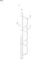
- Fig. 1 demonstrates a general front view of an ice tray with an insulating frame according to the present invention.
- Fig. 2 demonstrates a side view of the ice tray according to the present invention.
- Fig. 3 demonstrates a general rear view of the ice tray according to the present invention.
- Fig. 4 demonstrates a general perspective view of the ice tray according to the present invention.
- Fig. 5 demonstrates a general perspective view of the insulating frame according to the present invention.
- the present invention relates to a refrigeration appliance preferably with a plurality of compartments such as fresh food and freezer compartments, said appliance further having an ice making device comprising a vertically disposed ice tray (1) to accommodate ice cubes, as will be delineated hereinafter.
- Ice tray (1) to be used in the ice making device for the production of clear pieces of ice.
- Ice tray (1) comprises ice piece holes (2) in neighboring vertical columns (6), an insulating frame (3), ice tray grooves (4) and surface retaining means (5).
- Ice making device has conventional heat exchange circuit components (compressor, condenser, expansion valve, evaporator and interconnecting lines) (not shown) to circulate a refrigerant fluid.
- compressor condenser
- expansion valve expansion valve
- evaporator and interconnecting lines interconnecting lines
- refrigerant cools the regions that surround the evaporator by flowing therethrough
- a water curtain flowing over the surface of the ice tray (1) in direct thermal communication with said evaporator causes ice formation within ice cube holes (2) of the ice tray (1).
- Evaporator tubes can for instance be disposed so as to extend within inner frame portions of the ice tray (1).
- Ice tray (1) is aligned to be vertical and ice piece holes (2) form a rectangular matrix frame with the lower edge thereof extending in parallel to the horizontal direction. Ice tray (1) can be attached to an appropriate wall portion of the refrigerator by surface retaining means (5) so as to be cooled by evaporator coils passed between said ice tray (1) and said wall portion.
- Clear ice is formed by providing a flow of water cascading over ice piece holes (2), as water comes into contact with the cooled surface of ice piece holes (2), layers of ice are formed and dissolved air, minerals and dust particles are removed by flowing water. Therefore, ice pieces/cubes are formed by fractional freezing.
- an insulating frame (3) made of heat insulating material such as rubber is placed in ice tray grooves (4) on ice tray (1). In this manner, contact between neighboring ice cubes is prevented and individual ice cubes are produced. It is to be noted that the insulating frame (3) extend slightly over the surface plane formed by the imaginary open side end surfaces of the ice cube holes (2) so that two neighboring ice cube is prevented from joining to each other.
- Ice cubes can be conventionally removed from ice tray (1) by heating the surface of ice tray (1) by circulating hot pre-condensed refrigerant through the evaporator coils. This causes the ice closest to the surface of ice piece holes (2) to melt and the individual ice cubes to be detached from their respective ice piece holes (2). Formed ice is stored in an ice reservoir of the freezer compartment.
- the present invention makes use of placing an additional insulating frame (3) around the individual holes of the metal ice tray (1).
- noise from the breaking down of large ice slabs and the need for a wide storage compartment are eliminated and more space in the refrigerator becomes available for other use.
- unwanted dust particles and minerals are removed from the forming ice by continuously flowing water, resulting in clear ice.
- the ice produced has a clear and pleasing appearance depending on the amount of air present.
- a refrigeration appliance having at least one compartment and an ice making device disposed in said compartment, said ice making device comprising a vertically disposed ice tray (1) to accommodate ice pieces formed in a plurality of ice piece holes (2) of said ice tray (1).
- said ice tray (1) comprises an insulating frame (3) covering areas of said ice tray (1) in the manner that outer open ends of said ice piece holes (2) are surrounded by said insulating frame (3) so as to prevent connection of ice pieces in neighboring ice piece holes (2) during ice formation within at least two of the neighboring ice piece holes (2) of said ice tray (1).
- said insulating frame (3) is made of heat insulating material.
- said insulating frame (3) is made of rubber.
- said ice tray (1) has surface retaining means (5) to be attached to a refrigerator wall surface.
- said insulating frame (3) is placed into ice tray grooves (4) extending between neighboring ice piece holes (2) and around the perimeter of said ice tray (1).
- said insulating frame (3) extends over the surface plane formed by the outer open side ends of the ice cube holes (2) in operational position.
- an ice tray (1) for an ice maker in the refrigerator is proposed such that individual pieces of clear ice are produced by flowing water over ice cube holes (2).
- ice is formed by fractional freezing and dissolved air, minerals and dust particles are removed by flowing water, resulting in clear ice.
- Formation of individual ice cubes is ensured by utilizing an insulating frame (3) made of heat insulating material such as rubber placed in insulating frame grooves (4) on ice tray (1) to prevent contact between ice cubes.
Landscapes
- Engineering & Computer Science (AREA)
- Physics & Mathematics (AREA)
- Mechanical Engineering (AREA)
- Thermal Sciences (AREA)
- General Engineering & Computer Science (AREA)
- Devices That Are Associated With Refrigeration Equipment (AREA)
Abstract
A refrigeration appliance having at least one compartment and an ice making device disposed in said compartment, said ice making device comprising a vertically disposed ice tray (1) to accommodate ice pieces formed in a plurality of ice piece holes (2) of said ice tray (1) characterized in that: said ice tray (1) comprises an insulating frame (3) covering areas of said ice tray (1) in the manner that outer open ends of said ice piece holes (2) are surrounded by said insulating frame (3) so as to prevent connection of ice pieces in neighboring ice piece holes (2) during ice formation within at least two of the neighboring ice piece holes (2) of said ice tray (1).
Description
The present invention relates to a tray for an ice maker in the fresh food compartment of or a separate unit from a refrigerator that produces clear pieces of ice.
It is well-known that during the ice formation process, air that was dissolved in freezing water is transferred to water that has not yet frozen. As ice crystals are formed, there is dissolved air build-up in liquid water and as a result, air accumulates just below the freezing surface of ice. When concentration of dissolved air reaches a certain threshold, bubble formation can be observed below the freezing surface. During rapid freezing, a large number of very small bubbles can form, which cause the ice to have a cloudy appearance. It is possible to prevent formation of bubbles and obtain clear ice by slowing down the freezing process, however this requires a long time (6-10 hours). In order to obtain clear ice in shorter amounts of time (20-30 minutes), a constant flow of water on the freezing surface must be present. As freezing water is not stationary but flowing, dissolved air is carried away by the water flow and does not accumulate on the freezing surface. In this way, formation of bubbles is prevented. Commercially available ice makers operate with this principle. Though products with different geometries are available, their underlying ice making principles remain the same.
It is also well-known that, in the ice formation process by a coolant recycle refrigerant system, components such as compressor, condenser, expansion valve, evaporator and interconnecting lines are involved. Typically, an appropriate refrigerant at low pressure is compressed by the compressor, increasing the temperature and pressure thereof. The high temperature and high pressure refrigerant is then received by the condenser through which it condenses from vapor to liquid phase. Typically, the refrigerant supplied to the evaporator cools the regions surrounding the evaporator by absorbing latent heat. As mentioned above, a water circulation system provides water in the form of a water curtain flowing over an ice-forming grid in the direct vicinity of the evaporator tubes.
Among others, a prior art publication in the technical field of the invention may be referred to as US7062936B2, which discloses a refrigerator and clear ice maker. The invention operates by continuously cascading a flow of water over a vertically oriented metal surface connected to an evaporator. As the water flows over the cool metal surface, it freezes layer by layer, forming clear ice. When ice formation cycle is complete, hot pre-condensed refrigerant is transferred to the evaporator from the outlet of the compressor by opening a bypass valve. In this manner, the metal surface is heated and clear ice formed is detached from the metal surface and stored until needed. Another example may be referred to as US8756951B2.
The present invention, on the other hand, addresses the situation where ice maker in a refrigerator compartment produces individual pieces of clear ice by providing water flow over a vertically positioned cooled metal surface. The invention produces individual pieces of clear ice directly, instead of a block of ice that needs to be broken down before use by the user or by the impact on the surface of a wide storage compartment.
The present invention provides an ice tray for an ice maker in the fresh food compartment of or a separate unit from a refrigerator that produces individual pieces of clear ice, as provided by the characterizing features defined in Claim 1.
Primary object of the present invention is to provide an ice tray for an ice maker that produces individual pieces of clear ice by providing water flow over a vertically positioned cooled metal ice tray, the individual holes of which are separated from each other by an additional insulating frame.
The invention proposes a refrigeration appliance with an ice making device having a vertically positioned ice tray in which an insulating frame covering areas of said ice tray prevents joining of ice pieces around neighboring ice holes. This is especially advantageous in that two neighboring ice cubes being formed cannot join to each other due to a number of reasons: mainly on the one hand, the insulating intermediate line covered by the insulating frame segments provides thermal insulation thereinbetween, and on the other hand, the insulating frame physically prevents interconnection as it extends over the surface plane of the ice piece holes’ open side surface planes.
Accompanying drawings are given solely for the purpose of exemplifying an ice tray for an ice maker, whose advantages over prior art were outlined above and will be explained in brief hereinafter.
The drawings are not meant to delimit the scope of protection as identified in the Claims, nor should they be referred to alone in an effort to interpret the scope identified in said Claims without recourse to the technical disclosure in the description of the present invention.
Fig. 1 demonstrates a general front view of an ice tray with an insulating frame according to the present invention.
Fig. 2 demonstrates a side view of the ice tray according to the present invention.
Fig. 3 demonstrates a general rear view of the ice tray according to the present invention.
Fig. 4 demonstrates a general perspective view of the ice tray according to the present invention.
Fig. 5 demonstrates a general perspective view of the insulating frame according to the present invention.
The following numerals are assigned to different part number used in the detailed description:
1) Ice tray
2) Ice piece holes
3) Insulating frame
4) Ice tray grooves
5) Surface retaining means
6) Column
Reference will now be made in detail to the embodiments of the present invention, examples of which are illustrated in the accompanying drawings. The present invention relates to a refrigeration appliance preferably with a plurality of compartments such as fresh food and freezer compartments, said appliance further having an ice making device comprising a vertically disposed ice tray (1) to accommodate ice cubes, as will be delineated hereinafter.
The present invention proposes an ice tray (1) to be used in the ice making device for the production of clear pieces of ice. Ice tray (1) comprises ice piece holes (2) in neighboring vertical columns (6), an insulating frame (3), ice tray grooves (4) and surface retaining means (5).
Ice making device has conventional heat exchange circuit components (compressor, condenser, expansion valve, evaporator and interconnecting lines) (not shown) to circulate a refrigerant fluid. Typically, while the refrigerant cools the regions that surround the evaporator by flowing therethrough, a water curtain flowing over the surface of the ice tray (1) in direct thermal communication with said evaporator causes ice formation within ice cube holes (2) of the ice tray (1). Evaporator tubes can for instance be disposed so as to extend within inner frame portions of the ice tray (1).
Ice tray (1) is aligned to be vertical and ice piece holes (2) form a rectangular matrix frame with the lower edge thereof extending in parallel to the horizontal direction. Ice tray (1) can be attached to an appropriate wall portion of the refrigerator by surface retaining means (5) so as to be cooled by evaporator coils passed between said ice tray (1) and said wall portion.
Clear ice is formed by providing a flow of water cascading over ice piece holes (2), as water comes into contact with the cooled surface of ice piece holes (2), layers of ice are formed and dissolved air, minerals and dust particles are removed by flowing water. Therefore, ice pieces/cubes are formed by fractional freezing.
To prevent the formation of a single combined block of ice instead of individual ice pieces, an insulating frame (3) made of heat insulating material such as rubber is placed in ice tray grooves (4) on ice tray (1). In this manner, contact between neighboring ice cubes is prevented and individual ice cubes are produced. It is to be noted that the insulating frame (3) extend slightly over the surface plane formed by the imaginary open side end surfaces of the ice cube holes (2) so that two neighboring ice cube is prevented from joining to each other.
Ice cubes can be conventionally removed from ice tray (1) by heating the surface of ice tray (1) by circulating hot pre-condensed refrigerant through the evaporator coils. This causes the ice closest to the surface of ice piece holes (2) to melt and the individual ice cubes to be detached from their respective ice piece holes (2). Formed ice is stored in an ice reservoir of the freezer compartment.
To this end, the present invention makes use of placing an additional insulating frame (3) around the individual holes of the metal ice tray (1). In this manner, noise from the breaking down of large ice slabs and the need for a wide storage compartment are eliminated and more space in the refrigerator becomes available for other use. In addition, unwanted dust particles and minerals are removed from the forming ice by continuously flowing water, resulting in clear ice. The ice produced has a clear and pleasing appearance depending on the amount of air present.
In one embodiment of the present invention, a refrigeration appliance having at least one compartment and an ice making device disposed in said compartment, said ice making device comprising a vertically disposed ice tray (1) to accommodate ice pieces formed in a plurality of ice piece holes (2) of said ice tray (1).
In a further embodiment of the present invention, said ice tray (1) comprises an insulating frame (3) covering areas of said ice tray (1) in the manner that outer open ends of said ice piece holes (2) are surrounded by said insulating frame (3) so as to prevent connection of ice pieces in neighboring ice piece holes (2) during ice formation within at least two of the neighboring ice piece holes (2) of said ice tray (1).
In a further embodiment of the present invention, said insulating frame (3) is made of heat insulating material.
In a further embodiment of the present invention, said insulating frame (3) is made of rubber.
In a further embodiment of the present invention, said ice tray (1) has surface retaining means (5) to be attached to a refrigerator wall surface.
In a further embodiment of the present invention, said insulating frame (3) is placed into ice tray grooves (4) extending between neighboring ice piece holes (2) and around the perimeter of said ice tray (1).
In a further embodiment of the present invention, said insulating frame (3) extends over the surface plane formed by the outer open side ends of the ice cube holes (2) in operational position.
Therefore, an ice tray (1) for an ice maker in the refrigerator is proposed such that individual pieces of clear ice are produced by flowing water over ice cube holes (2). As water comes into contact with the cooled surface of ice cube holes (2), ice is formed by fractional freezing and dissolved air, minerals and dust particles are removed by flowing water, resulting in clear ice. Formation of individual ice cubes is ensured by utilizing an insulating frame (3) made of heat insulating material such as rubber placed in insulating frame grooves (4) on ice tray (1) to prevent contact between ice cubes.
Claims (6)
- A refrigeration appliance having at least one compartment and an ice making device disposed in said compartment, said ice making device comprising a vertically disposed ice tray (1) to accommodate ice pieces formed in a plurality of ice piece holes (2) of said ice tray (1) characterized in that;said ice tray (1) comprises an insulating frame (3) covering areas of said ice tray (1) in the manner that outer open ends of said ice piece holes (2) are surrounded by said insulating frame (3) so as to prevent connection of ice pieces in neighboring ice piece holes (2) during ice formation within at least two of the neighboring ice piece holes (2) of said ice tray (1).
- A refrigeration appliance as in Claim 1, characterized in that said insulating frame (3) is made of heat insulating material.
- A refrigeration appliance as in Claim 2, characterized in that said insulating frame (3) is made of rubber.
- A refrigeration appliance as in Claim 1 or 2, characterized in that said ice tray (1) has surface retaining means (5) to be attached to a refrigerator wall surface.
- A refrigeration appliance as in Claim 1 or 2, characterized in that said insulating frame (3) is placed into ice tray grooves (4) extending between neighboring ice piece holes (2) and around the perimeter of said ice tray (1).
- A refrigeration appliance as in Claim 1, 2 or 5, characterized in that said insulating frame (3) extends over the surface plane formed by the outer open side ends of the ice cube holes (2) in operational position.
Applications Claiming Priority (2)
| Application Number | Priority Date | Filing Date | Title |
|---|---|---|---|
| TRA2016/12357 | 2016-09-01 | ||
| TR2016/12357A TR201612357A2 (en) | 2016-09-01 | 2016-09-01 | Refrigeration appliance with integrated ice making device ice tray |
Publications (1)
| Publication Number | Publication Date |
|---|---|
| WO2018041519A1 true WO2018041519A1 (en) | 2018-03-08 |
Family
ID=59626589
Family Applications (1)
| Application Number | Title | Priority Date | Filing Date |
|---|---|---|---|
| PCT/EP2017/069703 Ceased WO2018041519A1 (en) | 2016-09-01 | 2017-08-03 | Refrigeration appliance with integrated ice making device |
Country Status (2)
| Country | Link |
|---|---|
| TR (1) | TR201612357A2 (en) |
| WO (1) | WO2018041519A1 (en) |
Cited By (2)
| Publication number | Priority date | Publication date | Assignee | Title |
|---|---|---|---|---|
| US11009281B1 (en) | 2020-07-15 | 2021-05-18 | Haier Us Appliance Solutions, Inc. | Ice making assemblies and removable nozzles therefor |
| US11920845B2 (en) | 2020-10-15 | 2024-03-05 | Haier Us Appliance Solutions, Inc. | Flow rate control method for an ice making assembly |
Citations (7)
| Publication number | Priority date | Publication date | Assignee | Title |
|---|---|---|---|---|
| US3952539A (en) * | 1974-11-18 | 1976-04-27 | General Motors Corporation | Water tray for clear ice maker |
| JPH0229576A (en) * | 1989-06-05 | 1990-01-31 | Fuji Electric Co Ltd | Flowing water type ice making machine |
| JP2005180823A (en) * | 2003-12-19 | 2005-07-07 | Hoshizaki Electric Co Ltd | Automatic ice making machine |
| US7062936B2 (en) | 2003-11-21 | 2006-06-20 | U-Line Corporation | Clear ice making refrigerator |
| EP2310771A1 (en) * | 2008-07-07 | 2011-04-20 | Arçelik Anonim Sirketi | A cooling device |
| US20140165617A1 (en) * | 2012-12-13 | 2014-06-19 | Whirlpool Corporation | Clear ice maker with warm air flow |
| US8756951B2 (en) | 2011-06-22 | 2014-06-24 | Whirlpool Corporation | Vertical ice maker producing clear ice pieces |
-
2016
- 2016-09-01 TR TR2016/12357A patent/TR201612357A2/en unknown
-
2017
- 2017-08-03 WO PCT/EP2017/069703 patent/WO2018041519A1/en not_active Ceased
Patent Citations (7)
| Publication number | Priority date | Publication date | Assignee | Title |
|---|---|---|---|---|
| US3952539A (en) * | 1974-11-18 | 1976-04-27 | General Motors Corporation | Water tray for clear ice maker |
| JPH0229576A (en) * | 1989-06-05 | 1990-01-31 | Fuji Electric Co Ltd | Flowing water type ice making machine |
| US7062936B2 (en) | 2003-11-21 | 2006-06-20 | U-Line Corporation | Clear ice making refrigerator |
| JP2005180823A (en) * | 2003-12-19 | 2005-07-07 | Hoshizaki Electric Co Ltd | Automatic ice making machine |
| EP2310771A1 (en) * | 2008-07-07 | 2011-04-20 | Arçelik Anonim Sirketi | A cooling device |
| US8756951B2 (en) | 2011-06-22 | 2014-06-24 | Whirlpool Corporation | Vertical ice maker producing clear ice pieces |
| US20140165617A1 (en) * | 2012-12-13 | 2014-06-19 | Whirlpool Corporation | Clear ice maker with warm air flow |
Cited By (2)
| Publication number | Priority date | Publication date | Assignee | Title |
|---|---|---|---|---|
| US11009281B1 (en) | 2020-07-15 | 2021-05-18 | Haier Us Appliance Solutions, Inc. | Ice making assemblies and removable nozzles therefor |
| US11920845B2 (en) | 2020-10-15 | 2024-03-05 | Haier Us Appliance Solutions, Inc. | Flow rate control method for an ice making assembly |
Also Published As
| Publication number | Publication date |
|---|---|
| TR201612357A2 (en) | 2018-03-21 |
Similar Documents
| Publication | Publication Date | Title |
|---|---|---|
| CN102221276A (en) | Ice making device for refrigerator and refrigerator with same | |
| US8863537B2 (en) | Single evaporator refrigeration system for multi-compartment refrigerator appliance with isolated air flows | |
| RU2477427C2 (en) | Refrigerator and evaporator for such refrigerator | |
| US20180080699A1 (en) | Modular cooling and low energy ice | |
| US20150135758A1 (en) | Refrigerator appliance and an ice making assembly for a refrigerator appliance | |
| JP6678542B2 (en) | refrigerator | |
| WO2018041519A1 (en) | Refrigeration appliance with integrated ice making device | |
| US9316427B2 (en) | Direct contact icemaker with chambered air cooling system | |
| US3481154A (en) | Means to retain food and drink items at their prepared temperatures | |
| JP2005156105A (en) | refrigerator | |
| CN103597302B (en) | refrigerator | |
| JP2014077615A (en) | Refrigerator | |
| CN107062748B (en) | refrigerator | |
| TWI722397B (en) | refrigerator | |
| CN114076466B (en) | Air-cooled refrigerator with evaporator arranged at bottom of refrigerator body | |
| EP3757484B1 (en) | Refrigerator appliance | |
| WO2015165512A1 (en) | Refrigeration appliance having an anti-condensation arrangement | |
| JP2007078264A (en) | Refrigerator-freezer | |
| JP7012139B2 (en) | refrigerator | |
| JP6261432B2 (en) | refrigerator | |
| US11268748B2 (en) | Indirect air cooling for an ice maker within a refrigerator door | |
| CN102954652A (en) | Refrigerating tool | |
| JP6909966B2 (en) | refrigerator | |
| JP3942455B2 (en) | Refrigerator | |
| JP4904856B2 (en) | Heat pump water heater |
Legal Events
| Date | Code | Title | Description |
|---|---|---|---|
| 121 | Ep: the epo has been informed by wipo that ep was designated in this application |
Ref document number: 17752062 Country of ref document: EP Kind code of ref document: A1 |
|
| NENP | Non-entry into the national phase |
Ref country code: DE |
|
| 122 | Ep: pct application non-entry in european phase |
Ref document number: 17752062 Country of ref document: EP Kind code of ref document: A1 |