WO2018032961A1 - 一种管理信息的方法,装置及系统 - Google Patents
一种管理信息的方法,装置及系统 Download PDFInfo
- Publication number
- WO2018032961A1 WO2018032961A1 PCT/CN2017/095278 CN2017095278W WO2018032961A1 WO 2018032961 A1 WO2018032961 A1 WO 2018032961A1 CN 2017095278 W CN2017095278 W CN 2017095278W WO 2018032961 A1 WO2018032961 A1 WO 2018032961A1
- Authority
- WO
- WIPO (PCT)
- Prior art keywords
- next hop
- information
- message
- network device
- field
- Prior art date
Links
Images


Classifications
-
- H—ELECTRICITY
- H04—ELECTRIC COMMUNICATION TECHNIQUE
- H04L—TRANSMISSION OF DIGITAL INFORMATION, e.g. TELEGRAPHIC COMMUNICATION
- H04L45/00—Routing or path finding of packets in data switching networks
- H04L45/20—Hop count for routing purposes, e.g. TTL
-
- H—ELECTRICITY
- H04—ELECTRIC COMMUNICATION TECHNIQUE
- H04L—TRANSMISSION OF DIGITAL INFORMATION, e.g. TELEGRAPHIC COMMUNICATION
- H04L45/00—Routing or path finding of packets in data switching networks
- H04L45/02—Topology update or discovery
- H04L45/021—Ensuring consistency of routing table updates, e.g. by using epoch numbers
-
- H—ELECTRICITY
- H04—ELECTRIC COMMUNICATION TECHNIQUE
- H04L—TRANSMISSION OF DIGITAL INFORMATION, e.g. TELEGRAPHIC COMMUNICATION
- H04L12/00—Data switching networks
- H04L12/28—Data switching networks characterised by path configuration, e.g. LAN [Local Area Networks] or WAN [Wide Area Networks]
- H04L12/46—Interconnection of networks
- H04L12/4633—Interconnection of networks using encapsulation techniques, e.g. tunneling
-
- H—ELECTRICITY
- H04—ELECTRIC COMMUNICATION TECHNIQUE
- H04L—TRANSMISSION OF DIGITAL INFORMATION, e.g. TELEGRAPHIC COMMUNICATION
- H04L12/00—Data switching networks
- H04L12/66—Arrangements for connecting between networks having differing types of switching systems, e.g. gateways
-
- H—ELECTRICITY
- H04—ELECTRIC COMMUNICATION TECHNIQUE
- H04L—TRANSMISSION OF DIGITAL INFORMATION, e.g. TELEGRAPHIC COMMUNICATION
- H04L45/00—Routing or path finding of packets in data switching networks
- H04L45/54—Organization of routing tables
-
- H—ELECTRICITY
- H04—ELECTRIC COMMUNICATION TECHNIQUE
- H04L—TRANSMISSION OF DIGITAL INFORMATION, e.g. TELEGRAPHIC COMMUNICATION
- H04L45/00—Routing or path finding of packets in data switching networks
- H04L45/62—Wavelength based
-
- H—ELECTRICITY
- H04—ELECTRIC COMMUNICATION TECHNIQUE
- H04L—TRANSMISSION OF DIGITAL INFORMATION, e.g. TELEGRAPHIC COMMUNICATION
- H04L45/00—Routing or path finding of packets in data switching networks
- H04L45/74—Address processing for routing
- H04L45/745—Address table lookup; Address filtering
-
- H—ELECTRICITY
- H04—ELECTRIC COMMUNICATION TECHNIQUE
- H04L—TRANSMISSION OF DIGITAL INFORMATION, e.g. TELEGRAPHIC COMMUNICATION
- H04L47/00—Traffic control in data switching networks
- H04L47/10—Flow control; Congestion control
- H04L47/24—Traffic characterised by specific attributes, e.g. priority or QoS
- H04L47/2425—Traffic characterised by specific attributes, e.g. priority or QoS for supporting services specification, e.g. SLA
- H04L47/2433—Allocation of priorities to traffic types
Definitions
- the present application relates to the field of communications technologies, and in particular, to a method, device, and system for managing information.
- the SDN system includes a controller and a network device, wherein the controller can be used for performing flow control of the network, and the network device is configured to perform forwarding processing on the received data packet.
- the SDN technology is used to separate the control plane of the network device from the forwarding plane (also called the data plane), realize flexible control of network traffic, and accelerate the innovation of network services.
- the controller mainly uses the Border Gateway Protocol (BGP) to advertise or revoke routes to the forwarding device. When the controller advertises the route to the forwarding device, the next hop information and the route prefix are sent in bundles.
- Border Gateway Protocol Border Gateway Protocol
- next hop information and route prefix are saved in the routing table.
- the controller needs to send a revocation route message to the forwarding device to delete the route prefix, and the information of the next hop is automatically deleted.
- the next hop is associated with multiple route prefixes, multiple rerouting messages need to be sent to delete the multiple route prefixes. Therefore, in the prior art, when the controller needs to manage the information of the next hop, it needs to bundle the route prefix associated with it.
- the multiple route prefixes are associated with the same next hop, the multiple route prefixes need to be bundled separately. As a result, when the information of the next hop is managed, more system resources are occupied, which affects the efficiency of service processing.
- the present invention provides a method for managing information, which enables the controller to separately manage the next hop of the network device without bundling the route prefix, which effectively saves system resources and improves service processing efficiency.
- the present application provides a method of managing information, the method comprising: the controller generating a first message.
- the first message carries an address of a first next hop of the network device.
- the first message includes first identifier information, where the first identifier information is used to indicate that the network device deletes an address corresponding to the address of the first next hop in a next hop table saved by the network device.
- the entry of the first next hop The controller sends the first message to the network device, so that the network device deletes the entry of the first next hop according to the indication of the first identifier information.
- the network device deletes the first hop in the separately saved next hop table.
- the entry of the first next hop corresponding to the address of the next hop does not need to bind the route prefix and delete the first next hop by using a large number of revoked routing messages, thereby saving network resources.
- the next hop corresponding to the multiple routing entries is deleted, and multiple subsequent hops can be deleted. Routing entry. Therefore, only one message needs to be sent between the controller and the network device to quickly and batchly delete routing entries. The number of interactive messages between the controller and the forwarding device is reduced, system resources are saved, and service processing efficiency is improved.
- the first message is a first BGP update message (UPDATE Message) or a first path calculation unit interaction protocol (English: Path Computation Element Communication Protocol , PCEP) Message.
- UPDATE Message UPDATE Message
- PCEP Path Computation Element Communication Protocol
- the method further includes: first, the controller generates a second message, where the second message carries the The entry information of the second next hop of the network device.
- the entry information of the second next hop includes a mapping relationship between an address of the second next hop of the network device and attribute information of the second next hop.
- the second message includes second identifier information, where the second identifier information is used to indicate that the network device saves the entry information of the second next hop in a next hop table of the network device.
- the controller sends the second message to the network device, so that the network device saves the entry information of the second next hop in the network device according to the second identifier information. In the next hop table.
- the second next hop and the first next hop may be the same next hop, or may be different next hops.
- the attribute information type of the second next hop includes but is not limited to the types of the following parameters: the type of the next hop, such as the Internet Protocol (IP) network, and the Virtual Extensible Local Area Network (VXLAN). ), etc.; Band Width and load balancing ratio (Weight).
- the controller separately sends the next hop information to the network device, and does not need to bind the route prefix.
- the network device saves the next hop address and the next hop attribute information in the separately maintained next hop table, so that the controller separately manages the next hop information of the network device, and the separate management includes separately creating or updating the next hop. Jump information.
- the controller when the controller separately sends the next hop information to the network device, the controller carries the attribute information of the next hop associated with the next hop customized by the controller, and describes the next hop by using the attribute information of the next hop. Different differentiated features, for example, some applications need to describe the available bandwidth of the next hop, the load balancing ratio of the next hop, and so on.
- the network device can obtain the attribute information of the next hop in the next hop table, and send the attribute information of the next hop to a forwarding information table (English: Forwarding Information Base, FIB) for guiding the report. Text forwarding.
- FIB Forwarding Information Base
- the second message is a second BGP UPDATE message or a second PCEP Message.
- the present application provides a method for managing information, where the method includes: the controller generates a first message, where the first message carries entry information of a first next hop of the network device.
- the entry information of the first next hop includes a mapping relationship between an address of the first next hop of the network device and attribute information of the first next hop.
- the first message includes first identifier information, where the first identifier information is used to indicate that the network device saves the entry information of the first next hop in a next hop table of the network device.
- the controller sends the network device Sending the first message, so that the network device saves the entry information of the first next hop in the next hop table of the network device according to the first identifier information.
- the method further includes: first, the controller determines a control routing protocol (CRP) routing entry information, where the CRP routing entry information includes a mapping relationship between the routing prefix and the address of the third next hop.
- the controller generates a third message, where the third message carries the CRP routing entry information, and is used to advertise a CRP route.
- the third message includes third identifier information, where the third identifier information is used to indicate that the network device saves the CRP routing entry information in a CRP routing table of the network device.
- the controller sends the third message to the network device, so that the network device saves the CRP routing entry information in the CRP routing table according to the third identifier information, and according to the The CRP routing table guides packet forwarding.
- a separate CRP routing table is created on the network device, and is used to save the CRP routing entry information sent by the controller.
- the route advertised by the routing protocol between the CRP route and the network device is saved in a different routing table, so that the routing policy related to the CRP route does not affect the route advertised in the routing protocol between the network devices.
- the CRP routing entry information further includes a routing priority, where the routing priority is used to identify a priority of the CRP routing when used to guide packet forwarding.
- the client By carrying the route priority in the CRP routing entry, you can flexibly set the CRP route priority. For example, you can set the CRP route as the preferred route to control the traffic using the routes advertised by the controller. For the subsequent complex policy control for routing, it can be completed by upgrading the controller. It is not necessary to implement complex policies like all existing routing policies, such as BGP routing policies. Therefore, the flow control is simpler and more flexible.
- the client considers that the internally deployed IGP route should be trusted, and the external route is not trusted.
- the priority of the CRP route may also be set lower than the intermediate system.
- the priority of the intermediate system to intermediate system (ISIS) route and the Open Shortest Path First (OSPF) route It can be seen that by setting the priority of the CRP route, the different needs of the customer can be met.
- the CRP routing entry information further includes attribute information of the third next hop, and the attribute information of the third next hop includes one or more of the following next hops. Attribute information type: bandwidth, load balancing ratio, and type of next hop.
- the CRP routing entry information carries the attribute information of the next hop, so that the network device can obtain the attribute information of the next hop in the CRP routing table, and send the attribute information of the next hop to the FIB. Guide the message forwarding.
- the information of the next hop is sent to the FIB table, and the packet forwarding is guided based on the attribute information of the next hop. Make traffic control more flexible.
- the third message is a third border gateway protocol update message BGPUPDATE message or a third path calculation unit communication protocol message PCEP Message.
- the third BGP UPDATE message includes a multi-protocol reachable network layer reachability information MP_REACH_NLRI attribute field.
- the MP_REACH_NLRI attribute field includes a sub-address family identifier SAFI field, a network layer reachability information NLRI field, and a next hop information field.
- the SAFI field indicates that the MP_REACH_NLRI attribute field is encapsulated based on an encapsulation format supported by the BGP synchronization address family, and carries the third identification information.
- the NLRI field carries the route prefix, and the next hop information field carries the address of the third next hop.
- the third BGP UPDATE message further includes a route synchronization attribute Route Synchronization Attribute field, where the Route Synchronization Attribute field carries the route priority.
- the third BGP UPDATE message further includes a next hop attribute Next Hop Attribute field, where the Next Hop Attribute field carries attribute information of the third next hop.
- the Next Hop Attribute field includes at least one sub-TLV field, and the attribute information type of each of the next hops corresponds to one of the at least one sub-TLV field, and each sub-TLV
- the field includes a T field, an L field, and a V field, where the T field indicates any one of the attribute information types of the next hop, and the V field indicates that the attribute information type is determined based on the corresponding next hop. Content.
- the third PCEP Message includes a message type Message-Type field, a route object Route object field, and a next hop object Next Hop object field.
- the Message-Type field carries the third identification information.
- the Route object field carries the route prefix.
- the Next Hop object field carries an address of the third next hop.
- the third PCEP message further includes a route attribute object, a Route Attribute object field, where the Route Attribute object field carries the route priority.
- the third PCEP message further includes a Next Hop Attribute object field, where the Next Hop Attribute object field carries attribute information of the third next hop.
- the Next Hop Attribute object field includes at least one sub-TLV field, and an attribute information type of each next hop corresponds to one sub-TLV field in the at least one sub-TLV field, and each sub-TLV
- the fields all include a T field, an L field, and a V field, the T field indicating any one of types of attribute information of the next hop, the V field indicating a type of attribute information based on the corresponding next hop The content determined.
- the method further includes:
- the controller receives a fourth message sent by the network device.
- the fourth message carries the routing status report information, where the routing status report information includes a mapping relationship between the routing prefix and the status information of the CRP route.
- the controller updates the statistics of the route prefix according to the received routing status report information, as a basis for recalculating the CRP route.
- the status information of the CRP route includes, but is not limited to, the status of the route, such as whether the route is legal, whether Is preferred, whether it is sent to the FIB medium; the survival time of the route; the state of the next hop, such as whether the next hop is legal, whether it is used, etc.; the ratio of the next hop bandwidth occupation; the next hop packet loss rate; the next hop Packet delay; next hop survival time.
- the controller can obtain the routing status information of the network device in a real-time manner by using the routing status information reported by the network device in a timely manner. As a basis for adjusting the route, the controller improves the reliability and real-time performance of the traffic control.
- the method further includes: the controller receives a fifth message sent by the network device, the fifth message carries next hop status report information, and the next hop status report information includes an address of a fourth next hop The mapping relationship with the state information of the fourth next hop. Then, the controller updates the statistical information of the fourth next hop according to the received next hop status report information, as a basis for recalculating the next hop of the network device.
- the next hop status report information includes, but is not limited to, the status of the next hop, such as whether the next hop is legal, whether it is used, etc.; the next hop bandwidth occupation ratio; the next hop packet loss rate; the next hop packet delay Time; next hop survival time.
- the controller can obtain the status of the forwarding device in real time by using the next hop state information reported by the forwarding device in real time. As a calculation, the basis of the next hop is adjusted, and the reliability and real-time performance of the traffic control are improved.
- the embodiment of the present application provides a method for managing information, where the method includes: receiving, by a network device, a first message sent by a controller, where the first message carries an address of a first next hop of the network device The first message includes the first identification information.
- the network device deletes, according to the indication of the first identifier information, an entry of the first next hop corresponding to the address of the first next hop in the next hop table saved by the network device.
- the network device deletes the first hop table in the separately saved
- the entry of the first next hop corresponding to the address of the next hop does not need to be bundled with the route prefix, and the next hop that is unavailable is deleted by means of revocation of the route, thereby saving network resources.
- the next hop corresponding to the multiple hops can be deleted. may. Therefore, only one message needs to be sent between the controller and the network device to quickly and batchly delete routing entries. Therefore, the number of interactive messages between the controller and the forwarding device is greatly reduced, system resources are saved, and service processing efficiency is improved.
- the network device according to the indication of the first identifier information, deleting the entry of the first next hop, specifically includes:
- the network device searches for the next hop table, hits the entry of the first next hop, and deletes the entry of the first next hop by using the address of the first next hop as a key, according to the indication of the first identifier information.
- the entry of the first next hop is a key that is associated with the next hop table.
- the method further includes:
- the network device deletes a routing entry associated with the address of the first next hop.
- the method further includes:
- the network device receives the second message sent by the controller, and the second message carries the entry information of the second next hop of the network device.
- the entry information of the second next hop includes a mapping relationship between an address of the second next hop of the network device and attribute information of the second next hop.
- the second message includes second identification information.
- the network device saves the entry information of the second next hop in the next hop table according to the indication of the second identifier information.
- the network device receiving controller separately sends the next hop information and saves it in the separately managed next hop table, so that the controller separately manages the next hop information of the network device, and does not have to be bound.
- Route prefix Separate management includes creating or updating next hop information separately.
- the foregoing solution makes the controller more flexible for the next hop management of the network device; and effectively saves the information exchange between the controller and the network device, because the system resources occupied by the routing prefix are carried, and the information that the network device needs to parse is reduced. It also improves the business processing efficiency of network devices.
- the network device acquires attribute information of the second next hop, and the second next hop
- the attribute information is sent to the forwarding information table to guide packet forwarding.
- the network device may search for the next hop table by using the address of the second next hop as a key, and obtain attribute information of the second next hop.
- the controller When the controller separately sends the next hop information to the network device, it carries the attribute information of the next hop customized by the controller, and describes the different differentiated features from the other next hops by using the attribute information of the next hop, for example, a certain These applications need to describe the available bandwidth of the next hop, the load balancing ratio of the next hop, and so on.
- the network device may be configured to obtain the attribute information of the next hop in the next hop table, and send the attribute information of the next hop to the FIB table for guiding packet forwarding.
- the packet forwarding is guided, which makes the traffic control more flexible.
- the embodiment of the present application provides a method for managing information.
- the network device receives the first message sent by the controller, where the first message carries the information of the first next hop of the network device.
- the entry information of the first next hop includes a mapping relationship between an address of the first next hop of the network device and attribute information of the first next hop, where the first message includes first identifier information.
- the network device saves the entry information of the first next hop in the next hop table of the network device according to the indication of the first identifier information.
- the method further includes: The network device receives a third message sent by the controller, where the third message carries control routing protocol CRP routing entry information determined by the controller.
- the CRP routing entry information includes a mapping relationship between the routing prefix and the address of the third next hop, and the third message includes the third identifier information.
- the network device is based on The instruction of the third identifier information is used to save the CRP routing entry information in the local CRP routing table, and guide the packet forwarding according to the CRP routing table.
- the CRP routing entry information further includes a routing priority.
- the route priority is used to identify the priority of the CRP route when it is used to guide packet forwarding.
- the route priority By carrying the route priority in the CRP routing entry, you can flexibly set the CRP route priority. For example, you can set the CRP route as the preferred route to control the traffic using the routes advertised by the controller. For the subsequent complex policy control for routing, it can be completed by upgrading the controller. It is not necessary to implement complex policies like all existing routing policies, such as BGP routing policies. Therefore, the flow control is simpler and more flexible.
- the client considers that the internally deployed IGP route should be trusted, and the external route is not trusted should not be preferred.
- the CRP route priority can also be set lower than the ISIS route. And the priority of OSPF routes. It can be seen that by setting the priority of the CRP route, the different needs of the customer can be met.
- the CRP routing entry information includes attribute information of the first next hop, and the attribute information of the first next hop includes one or more of the following The type of attribute information for one hop: bandwidth, load balancing ratio, and type of next hop.
- the CRP routing entry information carries the attribute information of the next hop, so that the network device can obtain the attribute information of the next hop in the CRP routing table, and send the attribute information of the next hop to the FIB. Guide the message forwarding.
- the packet forwarding is guided based on the attribute information of the next hop, so that the traffic control is more flexible.
- the method further includes:
- the controller receives a fourth message sent by the network device.
- the fourth message carries the routing status report information, where the routing status report information includes a mapping relationship between the routing prefix and the status information of the CRP route.
- the controller updates the statistics of the route prefix according to the received routing status report information, as a basis for recalculating the CRP route.
- the status information of the CRP route includes, but is not limited to, the status of the route, such as whether the route is legal, whether it is preferred, whether it is sent to the FIB, the survival time of the route, and the status of the next hop, such as whether the next hop is legal. Whether it is used, etc.; next hop bandwidth occupation ratio; next hop packet loss rate; next hop packet delay; next hop survival time.
- the controller can obtain the routing status information of the network device in a real-time manner by using the routing status information reported by the network device in a timely manner. As a basis for adjusting the route, the controller improves the reliability and real-time performance of the traffic control.
- the fourth message is a fourth BGP UPDATE Message or a fourth PCEP Message.
- the fourth BGP UPDATE message includes an MP_REACH_NLRI attribute field and a route status report attribute Route Status Report Attribute field;
- the MP_REACH_NLRI attribute field includes an NLRI field, where the NLRI field is used to carry the route prefix;
- the Report Attribute field is used to carry status information of the CRP route.
- the Route Status Report Attribute field includes at least one sub-TLV field, and a status information type of each of the CRP routes corresponds to one of the at least one sub-TLV field, each sub- The TLV field includes a T field, an L field, and a V field, where the T field indicates any one of the status information types of the CRP route, and the V field indicates that the status information type is determined based on the corresponding CRP route. content.
- the fourth PCEP message includes a message type Message-Type field, a route object Route object field, and a route status report attribute object Route Status Report Attribute object field; the Message-Type field indicates that the fourth PCEP Message is used to The controller sends the routing status report information, where the Route object field carries the route prefix, and the Route Status Report Attribute object field carries status information of the CRP route.
- the Route Status Report Attribute object field includes at least one sub-TLV field, and a status information type of each of the CRP routes corresponds to one of the at least one sub-TLV field, and each Each of the sub-TLV fields includes a T field, an L field, and a V field, where the T field indicates any one of the status information types of the CRP route, and the V field indicates that the status information type is determined based on the corresponding CRP route. Content.
- the method further includes: the controller receives a fifth message sent by the network device, the fifth message carries next hop status report information, and the next hop status report information includes an address of a fourth next hop The mapping relationship with the state information of the fourth next hop. Then, the controller updates the statistical information of the fourth next hop according to the received next hop status report information, as a basis for recalculating the next hop of the network device.
- the next hop status report information includes, but is not limited to, the status of the next hop, such as whether the next hop is legal, whether it is used, etc.; the next hop bandwidth occupation ratio; the next hop packet loss rate; the next hop packet delay Time; next hop survival time.
- the controller can obtain the status of the forwarding device in real time by using the next hop state information reported by the forwarding device in real time. As a calculation, the basis of the next hop is adjusted, and the reliability and real-time performance of the traffic control are improved.
- the fifth message is a fifth BGP UPDATE Message or a fifth PCEP Message.
- the fifth BGP UPDATE message includes a multi-protocol reachable network layer reachability information MP_REACH_NLRI attribute field and a next hop status report attribute Next Hop Status Report Attribute field;
- the MP_REACH_NLRI attribute field includes a network layer reachability information NLRI field,
- the NLRI field is used to carry the address of the fourth next hop, and the Next Hop Status Report Attribute field is used to carry status information of the fourth next hop.
- the Next Hop Status Report The Attribute field includes at least one sub-TLV field, and the status information type of each next hop corresponds to one of the at least one sub-TLV field, and each sub-TLV field includes a T field, an L field, and a V field.
- the T field indicates any one of the status information types of the next hop, and the V field indicates content determined based on the status information type of the corresponding next hop.
- the fifth PCEP message includes a message type Message-Type field, a next hop object Next Hop object field, and a next hop status report attribute object Next Hop Status Report Attribute object field; the Message-Type field indicates the fifth PCEP Message And sending, by the controller, the next hop status report information, where the Next Hop object field carries an address of the fourth next hop, where the Next Hop Status Report Attribute object field carries the fourth next hop Status information of the jump.
- the Next Hop Status Report Attribute object field includes at least one sub-TLV field, and a status information type of each next hop corresponds to one of the at least one sub-TLV field, and each Each of the sub-TLV fields includes a T field, an L field, and a V field, where the T field indicates any one of the status information types of the next hop, and the V field indicates a status information type based on the corresponding next hop. The content determined.
- the embodiment of the present application provides a controller for performing the first aspect, any possible implementation manner of the first aspect, the second aspect, or the method in any possible implementation manner of the second aspect.
- the controller comprises means for performing the method of the first aspect, any possible implementation of the first aspect, the second aspect or any possible implementation of the second aspect.
- the embodiment of the present application provides a network device, where the third aspect, any possible implementation manner of the third aspect, the fourth aspect, or the method in any possible implementation manner of the fourth aspect is performed.
- the controller comprises means for performing the third aspect, any possible implementation of the third aspect, the fourth aspect or a method of any of the possible implementations of the fourth aspect.
- the embodiment of the present application provides a communication system, including the controller provided by the fifth aspect and the network device provided by the sixth aspect.
- an embodiment of the present application provides a controller, where the controller includes: an input interface, an output interface, a processor, and a memory. Wherein, the input interface, the output interface, the processor and the memory can be connected by a bus system.
- the memory is for storing a program, instruction or code for executing a program, instruction or code in the memory, completing the first aspect, any possible implementation of the first aspect, the second aspect or the second aspect The method in any possible implementation.
- the embodiment of the present application provides a network device, where the network device includes: an input interface, an output interface, a processor, and a memory.
- the input interface, the output interface, the processor and the memory can be connected by a bus system.
- the memory is for storing a program, an instruction or a code
- the processor is for executing a program, an instruction or a code in the memory, completing the third aspect, any possible implementation manner of the third aspect, the fourth aspect or the fourth aspect The method in any possible implementation.
- the embodiment of the present application provides a communication system, including the controller provided by the eighth aspect and the network device provided by the ninth aspect.
- the embodiment of the present application provides a computer readable storage medium, configured to store a computer program, where the computer program is used to execute the first aspect, any possible implementation manner of the first aspect, the second aspect, and the Any possible implementation of the second aspect, the third aspect, any possible implementation of the third aspect, the fourth party Or an instruction of any possible implementation of the fourth aspect.
- FIG. 1 is a schematic diagram of an application scenario according to an embodiment of the present application
- FIG. 2 is a schematic flow chart of a method for managing information according to an embodiment of the present application
- FIG. 3 is a schematic diagram of an MP_UNREACH_NLRI field encapsulated by an encapsulation format supported by a BGP synchronization address family according to an embodiment of the present application;
- FIG. 4 is a schematic diagram of a TLV field in an unreachable NLRI field according to an embodiment of the present application
- FIG. 5 is a schematic diagram of a package format of a common message header of a PCEP message according to an embodiment of the present application
- FIG. 6 is a schematic diagram of a package format of a Next Hop object of a next hop object in a PCEP Message according to an embodiment of the present application
- FIG. 7 is a schematic diagram of an MP_REACH_NLRI field encapsulated by an encapsulation format supported by a BGP synchronization address family according to an embodiment of the present application;
- FIG. 8 is a schematic diagram of a TLV field in an NLRI field according to an embodiment of the present application.
- FIG. 9 is a schematic diagram of a package format of a routing object Route object in a PCEP Message according to an embodiment of the present application.
- FIG. 10 is a schematic diagram of a package format of a sub-object Sub-object in a route object Route object according to an embodiment of the present application
- FIG. 11 is a schematic diagram of a package format of a sub-object Sub-object in a route object Route object according to another embodiment of the present application.
- FIG. 12 is a schematic diagram of a controller according to an embodiment of the present application.
- FIG. 13 is a schematic diagram of a network device according to an embodiment of the present application.
- FIG. 14 is a schematic structural diagram of hardware of a controller according to an embodiment of the present application.
- FIG. 15 is a schematic structural diagram of hardware of a network device according to an embodiment of the present application.
- FIG. 1 shows an SDN 100 to which an embodiment of the present application is applied.
- the SDN 100 includes a controller 110 and a plurality of network devices 120.
- the controller 110 may also be referred to as a control device, a control system, and a control node.
- the controller 120 may be an intelligent network controller (SNC), but the embodiment of the present application is not limited thereto.
- SNC intelligent network controller
- the network device 120 can be used to forward the message.
- the network device may be a traditional router, a switch, or the like in a traditional path computation unit (PCE) network, or a routing network device such as a router or a switch in the SDN that controls the forwarding and separation.
- PCE path computation unit
- the application embodiment does not limit this.
- FIG. 2 shows five routers: R1 to R5, it should be understood that FIG. 2 exemplarily shows only one controller and five routers, which may include any other number of controllers and network devices, this application The embodiment does not limit this.
- the method 200 for information synchronization provided by the embodiment of the present application is described in detail below with reference to FIG.
- the method 200 can be applied to the SDN 100 shown in FIG. 1, but the embodiment of the present application is not limited thereto.
- the method includes:
- the controller generates a first message.
- the first message carries the address of the first next hop of the network device, where the first message includes the first identifier information, where the first identifier information is used to indicate the next hop table saved by the network device The entry of the first next hop corresponding to the address of the first next hop is deleted.
- the controller can be used to control traffic of the network.
- the controller can be the controller 110 shown in FIG.
- the network device may be specifically any one of R1 to R5 shown in FIG. 1.
- the controller may be specifically an SNC, but the embodiment of the present application does not limit this.
- the network device saves the information of the next hop to a table maintained by the network device separately, and the table is referred to as a “next hop table”.
- each next hop entry in the next hop table includes a mapping relationship between the address of the next hop and the attribute information of the next hop.
- the routing table includes a mapping relationship between the route prefix and the address of the next hop.
- the routing table may have multiple routing prefixes corresponding to the same next hop A. That is, there are multiple routing entries in the routing table. The routing prefixes of the multiple routing entries are different, but they all correspond to the same.
- the address of a next hop A In the network device, an entry is also included in the next hop table, which is used to include the address of the next hop A and the attribute information of the next hop A. The network device associates the entry of the next hop A with all routing entries of the routing table that use the address of the next hop A.
- all routing tables include a plurality of routing tables used by the network device to store routes advertised by different protocols.
- the network device independently maintains multiple next hop tables, where each next hop table corresponds to a routing table that stores routes advertised by each protocol, for example, next hop table 1 and ISIS.
- the routing table corresponds
- the next hop table 2 corresponds to the CRP routing table. That is, the plurality of next hop tables are respectively associated with the plurality of routing tables, in other words, there is a one-to-one mapping relationship between the plurality of next hop tables and the plurality of routing tables.
- all the routing entries of the address of the next hop can be found by using the address of the next hop as an index. It can be understood by those skilled in the art that other fields are used as indexes to find the next hop address. Corresponding routing entries are merely exemplary and should not be construed as limiting the application.
- the format of the next hop table can be as shown in Table 1: Table 1
- next hop table includes multiple next hop entries, including multiple fields:
- Next-Hop field indicates the next hop address
- Type field indicates the type of next hop access, such as IP network, VXLAN, etc.
- Band Width field indicates the available bandwidth of the next hop
- Weight field indicates the next hop load balancing ratio. Calculated as a percentage, 100 means that this next hop does not participate in load balancing.
- the "Status" field described above may be composed of 32 bit bits, each bit representing a next hop state.
- the encapsulation format of the "Status” field is shown in Table 2:
- V-valid where 1 indicates a legal next hop and 0 indicates an invalid next hop.
- V-valid where 0 is the legal next hop and 1 is the illegal next hop.
- the foregoing state information may also be represented by other values, which is not specifically limited in the embodiment of the present application.
- Status field may also be encapsulated in other package formats, which are merely exemplary and should not be construed as limiting the application.
- next hop entry information is merely an example and is not intended to limit the application.
- next hop entry information may include one or more of the various information, and does not have to include all the information.
- next hop entry information may also include only the information represented by other fields not listed herein, which is not specifically limited in this embodiment of the present application.
- the first message is a first BGP UPDATE Message.
- the first BGP UPDATE message includes a Multi-Protocol Unreach Network Layer Reachability Information (MP_UNREACH_NLRI) attribute field.
- MP_UNREACH_NLRI attribute field includes a Subsequent Address Family Identifier (SAFI) field and an unreachable network layer reachability information NLRI field.
- SAFI Subsequent Address Family Identifier
- the SAFI field indicates that the MP_UNREACH_NLRI attribute field is encapsulated based on an encapsulation format supported by the BGP synchronization address family, and carries the first identification information.
- the unreachable NLRI field carries an address of the first next hop.
- the first identifier information may be directly represented by a value of SAFI in the SAFI field of the BGP synchronization address family.
- the encapsulation format of the MP_UNREACH_NLRI added to the BGP synchronization address family is as shown in FIG. 3.
- the MP_UNREACH_NLRI can be understood as the multi-protocol extended attribute information of the network layer unreachable NLRI, which includes the address family information field and the unreachable NLRI domain.
- the address family information field includes an address family identifier field (English: Address Family Identifier, AFI) (2 bytes) and a SAFI field (1 byte).
- AFI Address Family Identifier
- the AFI field carries the address family identifier of the network layer protocol and is used to identify the network layer protocol. For example, AFI takes 1 for IPv4 and AFI for 2 for IPv6.
- the SAFI field identifies the type of the sub-address family. For example, SAFI takes 1 for unicast, SAFI takes 2 for multicast, and SAFI takes 128 for virtual private network (VPN).
- VPN virtual private network
- the AFI value is 1, and the SAFI value is 1, indicating that the NLRI field carries an IPv4 unicast route; the AFI value is 1, and the SAFI value is 128 indicates the BGP-VPNv4 route carried in the NLRI field; the AFI value is 1.
- the SAFI value of 4 indicates the BGP label route carried in the NLRI field.
- the BGP synchronization address family can be understood as an extended sub-address family in the IPv4 or IPv6 address family in the existing BGP protocol, that is, the AFI value can be 1 or 2.
- the value of SAFI can be determined according to standards set by the Internet Engineering Task Force (IETF).
- the unreachable NLRI field includes the unreachable NLRI field.
- the unreachable NLRI field may be identified by a binary ⁇ Length-Next Hop>.
- Length indicates the length of the next hop address field in bytes.
- Next Hop contains the next hop address, followed by padding bits to ensure that the end of the field conforms to the byte boundary, and the value of the padding bit is meaningless.
- the unreachable NLRI field may include a type length value TLV field (variable length).
- TLV field variable length
- a schematic diagram of the TLV field can be referred to FIG.
- the type T field indicates that the type of the TLV field is a BGP synchronization type
- the length L field indicates the length of the V field
- the value V field carries the content determined according to the BGP synchronization type.
- the L field value is 16 bits, that is, 2 bytes, indicating a specific length value of the V field.
- the V field is a 4-byte IPv4 address.
- the V field is a 16-byte IPv6 address
- the V field is a 2-byte next hop address. .
- Type 1 type listed herein as the BGP next hop synchronization type is merely an exemplary description and should not be construed as limiting the application.
- the embodiment of the present application does not exclude the possibility of indicating other types by Type1 or indicating the BGP next hop synchronization type by other means.
- the number of types of NLRI Types in the embodiments of the present application is also not particularly limited.
- the first message is a first PCEP Message.
- the first PCEP Message includes a message type Message-Type field and a next hop object Next Hop object field.
- the message-type field indicates that the first PCEP message is used to send the address of the first next hop to the network device, and is used to carry the first identifier information.
- the Next Hop object field carries an address of the first next hop.
- the first PCEP message may also be referred to as a PCE instantiated next hop message (PCE-initiated Next Hop Message).
- a PCEP Message consists of a common message header and a variable-length message body consisting of a series of objects.
- the first PCEP Message includes a common message header and the next hop object.
- FIG. 5 is a schematic diagram of a package format of a common message header of a first PCEP Message according to an embodiment of the present application.
- Version (Ver) field (3 bits): Identifies the PCEP version number, and the current version number is 1.
- Flags field (5 bits): tag, there is no tag currently defined, the allocated 5 bits is reserved, the sender must be set to 0, and the receiver must ignore.
- Message-Type field (8 bits): Message type. To be defined.
- the first PCEP message (for example, the PCE-initiated Next Hop Message) may be understood as a message type based on the Message-Type extension in the existing PCEP protocol.
- the value of -Type can be determined according to the standards set by the IETF.
- Message-Length field (16 bits): The total length of the PCEP message (including the length of the common header) in bytes.
- the encapsulation format of the Next Hop object of the next hop object is as shown in FIG. 6:
- the value of the object-class class (Object-Class) is to be defined and managed by the Internet Assigned Numbers Authrity (IANA).
- object type Object-Type, OT
- the object body Object body
- IPv4 unicast address when the value is 2, the Object body carries a 16-byte long IPv6 unicast address.
- the Object-Class and Object-Type together uniquely determine the Next Hop object.
- the Res field is filled with 0 when sent, and ignored when received.
- the Processing Rule Flag (P) field and the Ignore Tag (I) field are not used in this Route object and are set to 0.
- the value of the Object Length is the length of the Next Hop object, including the object header.
- the first identifier information is carried according to the extended Message-Type, and is used to indicate that the network device deletes the first next hop in the locally saved next hop table. The entry of the first next hop corresponding to the address.
- the first identification information is directly represented by the value of the Message-Type in the Message-Type field.
- the first PCEP Message further includes a status request parameter (English: Request Parameters, RP) object object field.
- the Message-Type field carries the first identifier information, and specifically includes that the Message-Type field and the RP object field jointly carry the first identifier information. That is, the first identification information is represented by the value of the Message-Type in the Message-Type field and the value of the R flag in the RP object field.
- the explanation of each field in the RP object can be referred to the relevant definition of RFC5440.
- the Message-Type field is used to identify that the first PCEP Message is a message for sending an address of the first next hop.
- the network device When the R flag in the RP object is set to 1, the network device deletes the entry of the first next hop corresponding to the address of the first next hop in the locally saved next hop table. That is, the Message-Type field and the RP object field jointly carry the first identification information.
- a field for carrying the first identifier information together with the Message-Type field is not limited to the RP object field, and may also be adopted by other existing or newly added fields. This application does not specifically limit this.
- the R flag listed here is set to 1, and the network device deletes the entry of the first next hop corresponding to the address of the first next hop in the locally saved next hop table, and the same does not The application constitutes any qualification.
- the network device deletes the entry of the first next hop when the R flag is set to 0 or other values.
- the embodiment of the present application does not exclude the possibility that the network device deletes the entry of the first next hop when the R flag is set to 0 or other values.
- the controller sends the first message to a network device.
- the network device receives the first message.
- the network device deletes the entry of the first next hop in the next hop table according to the indication of the first identifier information.
- the network device After receiving the first message, the network device searches for the entry in the next hop table by using the address of the first next hop carried in the first message as a key, if If the entry of the first next hop is hit, the entry of the first next hop is deleted in the next hop table. If the corresponding entry is not hit, the process ends.
- the method further includes:
- the network device deletes a routing entry associated with the address of the first next hop.
- each routing table may include a routing entry associated with the address of the third next hop.
- the third next hop address is used as an index to find all routing entries of the address using the third next hop, and delete the All routing entries associated with the address of the third next hop.
- the next hop corresponding to the multiple route prefixes is deleted, and multiple routing tables using the next hop can be deleted. item.
- 1000 routing prefixes correspond to the same next hop address, and the controller needs to delete the route associated with the 1000 routing prefixes, 1000 revocation routing messages need to be sent.
- the above 1000 routing prefixes are encapsulated in multiple revocation routing messages. After receiving the multiple revocation routing messages, the network device parses and deletes the routes one by one, thereby achieving the purpose of deleting the unavailable next hop.
- the method 200 may further include S206-S210:
- the controller determines entry information of the second next hop of the network device.
- the entry information of the second next hop includes a mapping relationship between an address of the second next hop and attribute information of the second next hop.
- the second next hop and the first next hop may be the same next hop, and the second next hop and the first next hop may also be different next hops. jump.
- the attribute information type of the second next hop includes but is not limited to the types of the following parameters: the type of the next hop access, such as IP, VXLAN, etc.; the available bandwidth (Band Width) and the load balancing ratio (Weight).
- the controller generates a second message, configured to send entry information of the second next hop.
- the controller generates a second message, where the second message carries the entry information of the second next hop interest.
- the second message includes second identifier information, where the second identifier information is used to indicate that the network device saves the entry information of the second next hop in a next hop table of the network device.
- the route information of the second next hop does not need to include a route prefix, so that the controller can separately send the information of the next hop to the network device.
- the second identifier information is used to indicate that the network device saves the entry information of the second next hop in the next hop table, and specifically includes:
- the second identifier information is used to indicate that the network device creates or updates entry information of the second next hop in the next hop table.
- the second message is a second BGP UPDATE message
- the second BGP UPDATE message includes multi-protocol reachable network layer reachability information (English: Multi-Protocol Reach Network Layer Reachability Information) , MP_UNREACH_NLRI) attribute field and next hop attribute Next Hop Attribute field.
- the MP_REACH_NLRI attribute field includes a sub-address family identifier SAFI field, a network layer reachability information NLRI field, and a next hop information field.
- the SAFI field indicates that the MP_REACH_NLRI attribute field is encapsulated based on an encapsulation format supported by the BGP synchronization address family, and carries the second identification information.
- the NLRI field carries an address of the second next hop.
- the Next Hop Attribute field carries attribute information of the second next hop.
- the Next Hop Attribute field includes at least one sub-TLV field, and an attribute information type of each next hop corresponds to one of the at least one sub-TLV field.
- Each sub-TLV field includes a T field, an L field, and a V field, where the T field indicates any one of types of attribute information of the second next hop, the V field indication is based on the corresponding The content determined by the type of attribute information of the next next hop.
- the second identifier information is directly represented by the value of SAFI in the SAFI field of the BGP synchronization address family.
- the BGP synchronization address family may be added to the existing BGP address family, and the second next hop entry information is encapsulated according to the encapsulation format supported by the newly added BGP synchronization address family.
- the encapsulation format of the MP_REACH_NLRI added to the BGP synchronization address family is as shown in FIG. 7 .
- FIG. 7 is a schematic diagram of an MP_REACH_NLRI attribute field encapsulated by an encapsulation format indicated by a BGP synchronization address family according to an embodiment of the present application.
- MP_REACH_NLRI can be understood as NLRI multi-protocol extended attribute information, which includes three parts: address family information domain, next hop information domain, and network layer reachability information (NLRI) domain.
- the BGP synchronization address family can be understood as an extended sub-address family in the IPv4 or IPv6 address family in the existing BGP protocol, that is, the AFI value can be 1 or 2.
- the value of SAFI can be determined according to standards set by the Internet Engineering Task Force (IETF).
- the next hop information field includes a next hop address length field (1 byte) and a next hop address field (variable length).
- the next hop address length field is used to identify the length of the next hop address field, and the length of the next hop address field is determined by the length identified by the next hop address length field.
- a 1-byte reserved field is left between the next hop information field and the NLRI field.
- the NLRI field includes the NLRI field.
- the NLRI field can be represented by a binary ⁇ Length-Prefix>.
- Length indicates the length of the route prefix in bytes.
- Prefix contains the route prefix, followed by the fill The bit is used to ensure that the end of the field conforms to the byte boundary, and the value of the padding bit is meaningless.
- the NLRI field includes a TLV field (variable length).
- FIG. 8 is a schematic diagram of a TLV field in an NLRI field according to an embodiment of the present application.
- the type T field indicates that the type of the TLV field is a BGP synchronization type
- the length L field indicates the length of the V field
- the value V field carries the content determined according to the BGP synchronization type.
- the BGP next hop synchronization type may be identified.
- the L field value is 16 bits, that is, 2 bytes; the V field is a route prefix of the length indicated by the L field value.
- the BGP synchronization type includes the BGP next hop synchronization type.
- Type 1 type listed herein as the BGP next hop synchronization type is merely an exemplary description and should not be construed as limiting the application.
- the embodiment of the present application does not exclude the possibility of indicating other types by Type1 or indicating the BGP next hop synchronization type by other means.
- the number of types of NLRI Types in the embodiments of the present application is also not particularly limited.
- the second message is a second PCEP Message.
- the second PCEP Message includes a message type Message-Type field, a next hop object Next Hop object field, and a next hop attribute object Next Hop Attribute object field.
- the Message-Type field is used to carry the second identifier information.
- the Next Hop object field carries an address of the second next hop.
- the Next Hop Attribute object field carries attribute information of the second next hop.
- the Next Hop Attribute object field includes at least one sub-TLV field, and an attribute information type of each next hop corresponds to one of the at least one sub-TLV field, each sub-
- the TLV field includes a T field, an L field, and a V field, where the T field indicates any one of types of attribute information of the next hop, and the V field indicates attribute information based on the corresponding next hop. The content determined by the type.
- the second identifier information is directly represented by a value of a Message-Type in the Message-Type field.
- the Message-Type in the second PCEP message may be understood as a message type based on the Message-Type extension in the existing PCEP protocol, and the value of the Message-Type may be determined according to a standard established by the IETF. By newly defining a value of Message-Type, it is used to indicate that the second PCEP Message is a message for updating or creating a next hop.
- the second PCEP message may also be referred to as a PCE instantiated next hop message PCE-initiated Nexthop Message.
- the second PCEP message further includes a request parameter (English: Request Parameters, RP) object object field.
- the Message-Type field is used to carry the second identifier information, and specifically includes that the Message-Type field and the RP object field jointly carry the second identifier information, that is, the second identifier information is used by the Message-Type field.
- the value of the Message-Type is represented together with the value of the R flag in the RP object field.
- the encapsulation format of the RP object and the interpretation of each field can refer to the related definition of RFC5440.
- the Message-Type field is used to identify that the second PCEP Message is a message for separately transmitting next hop information, and the next hop information includes at least a next hop address.
- the network device saves the entry information of the second next hop in the local next hop table. That is, the Message-Type field and the RP object field jointly carry the second identifier information.
- a field for carrying the second identifier information together with the Message-Type field is not limited to the foregoing RP object field, and may also be adopted by other existing or newly added fields. This application does not specifically limit this.
- the R flag is set to 0 here, and the network device saves the entry information of the second next hop in the local next hop table, and the same should not be limited.
- the embodiment of the present application does not exclude the possibility that the network device saves the entry information of the second next hop when the R flag is set to 1 or other values.
- the specific content or value of the TLV may be set according to the specific conditions of each message, and may adopt the same setting manner or different setting manners.
- the application does not limit this.
- the available bandwidth type can be identified; the L field is 2 bytes; and the V field is a value of a specific available bandwidth, such as 20000 kbit/sec.
- the load balancing ratio type can be identified; the L field is 2 bytes; the V field is a specific load balancing ratio, such as 50%, and identifies the next hop to participate in 50% load sharing.
- the types of attribute information of the next hop listed above are merely exemplary and should not be construed as limiting the application.
- the field for carrying the attribute information of the next hop is not limited to the above-mentioned Next Hop Attribute field or the Next Hop Attribute object field, and may be carried by other existing or newly added fields, which is not specifically limited in this application.
- the Type 1 type listed here is an available bandwidth type
- the Type 2 type is a load balancing ratio type
- the present application should not be limited in any way.
- the embodiment of the present application does not exclude the possibility of indicating other types through Type 1 and Type 2, or otherwise indicating the available bandwidth type and load balancing type.
- the number of types of attribute information of the next hop in the embodiment of the present application is also not particularly limited.
- the controller sends the second message to the network device.
- the controller sends the second message to the network device, so that the network device saves the entry information of the second next hop in the network device according to the second identifier information. In the next hop table.
- the controller itself saves the next hop table, and after determining the entry information of the second next hop, the controller saves the second next hop in the next hop table saved by itself Entry information.
- the network device receives the second message.
- the network device saves the entry information of the second next hop in the local next hop table.
- the network device saves the entry information of the second next hop in the next hop table, specifically:
- the network device After receiving the second message, the network device searches for the entry in the next hop table saved by using the address of the second next hop carried in the second message as a key, if the hit corresponds The entry of the second next hop is updated by using the entry information of the second next hop. If the corresponding entry is not hit, a new next hop entry is created, and the information of the second next hop is saved to the newly created next hop entry.
- the network device may process the default value according to the existing rule, for example, the bandwidth of the next hop is not limited.
- the load balancing ratio of the next hop is not set, and the type of next hop access is not specified.
- the controller can separately send the next hop information to the network device, so that the controller separately manages the next hop information of the network device. Separate management involves creating or updating next hop information separately without having to bind a route prefix.
- the foregoing solution makes the controller more flexible for the next hop management of the network device; and effectively saves the information exchange between the controller and the network device, because the system resources occupied by the routing prefix are carried, and the information that the network device needs to parse is reduced. It also improves the business processing efficiency of network devices. rate.
- the controller separately sends the next hop information to the network device
- the attribute information of the next hop customized by the controller is carried, so that the network device can obtain the attribute information of the next hop in the next hop table.
- the attribute information of the next hop is sent to the FIB table to guide packet forwarding.
- the method 200 may further include S211-S215:
- the controller determines a control routing protocol (CRP) routing entry information, where the CRP routing entry information includes a mapping relationship between the routing prefix and the address of the third next hop.
- CRP control routing protocol
- the third next hop and the first next hop may be the same next hop; or the third next hop and the second next hop may be the same next hop
- the first next hop, the second next hop, and the third next hop may both be the same next hop; or the first next hop, the second lower One hop and the third next hop are three different next hops.
- CRP refers to a protocol that runs between a controller and a network device and supports the controller to issue a route to the network device. Based on the CRP protocol, the network device saves the route generated and issued by the controller to a routing table maintained by the network device separately.
- the routing table is called a “CRP routing table”.
- the CRP protocol may be an extended protocol formed by extending an existing routing protocol, so as to carry a route sent by the controller to the network device, for example, a BGP extended protocol formed by extending an existing routing protocol BGP, or an existing PCEP protocol. Expansion of the extended PCEP protocol.
- the CRP protocol can also be an extension of the routing protocol used between newly created legacy network devices.
- the CRP protocol may also be a newly created protocol dedicated to the interaction between the controller and the legacy network device and carrying the routing information sent by the controller.
- the specific protocol of the route carrying the controller is not limited in this application.
- the traditional network device in the embodiment of the present application can be understood as a non-pure or hybrid SDN network device, such as the function of the traditional network device control and forwarding, and the SDN control forwarding and separation scenario.
- the CRP routing table can be understood as a routing table for storing routes issued by the controller to distinguish it from other forms of routing tables, such as a routing table for storing routes advertised between network devices.
- the network device saves the CRP routing table of the route advertised by the controller and saves the common BGP route (for example, the network).
- BGP routing table for routes advertised between devices.
- the CRP routing table includes multiple routing entries, which are called CRP routing entries.
- the routing information included in each CRP routing entry is called CRP routing entry information.
- the route that the controller advertises to the network device is called "CRP route.”
- the CRP routing table can be as shown in Table 3:
- the CRP routing table includes multiple CRP routing entries.
- Network field indicates the route prefix, which is usually expressed by destination address/mask (destination/Mask). If a natural mask is used, the mask can be omitted.
- Next-Hop field indicates the next hop address
- Status field indicates the routing status
- Preference field indicates a route priority; the route priority is used to indicate that the CRP route is used to guide the priority of packet forwarding. The smaller the value of the route priority, the higher the route priority.
- Topology field indicates the topology identifier of the network device. When the corresponding topology identifier is specified, the corresponding topology is used according to the specified identifier information. If no specific identifier is specified, the default global topology is used.
- Band Width field indicates the available bandwidth of the next hop.
- the information of each CRP routing entry includes at least the mapping relationship between the route prefix and the next hop address, and the information contained in other fields is optional information. Default configuration.
- the network device After receiving the packet, the network device forwards the packet to the next hop network device according to the CRP routing table.
- the "Status" field described above may be composed of 32 bits, each bit representing a routing state.
- the encapsulation format of the "Status” field is shown in Table 4:
- V—Valid 1 indicates a legal route, and 0 indicates an illegal route.
- 0xD0000000 The three bits of V, B, and D are 1, and the A bit is 0, indicating that the route is legal, optimal, and sent to the FIB, but the route is not activated.
- V—Valid where 0 is a legal route and 1 is an illegal route.
- 0 indicates that the route is sent to the forwarding information base (FIB)
- 1 indicates that the route is not sent to the FIB.
- the foregoing state information may also be represented by other values, which is not specifically limited in the embodiment of the present application.
- Status field may also be encapsulated in other package formats, which are merely exemplary and should not be construed as limiting the application.
- the controller calculates the CRP route by collecting network element resource information and network topology information of each network device, and determines the CRP routing entry information.
- the network element resource information includes, but is not limited to, label information, interface resource information, virtual local area network (VLAN) information, and a tunnel ID.
- the network topology information is information describing nodes and links in the network and connection relationships between the nodes.
- the controller can be based on various existing topology collection protocols, such as the Interior Gateway Protocol (IGP), the intermediate system to intermediate system (ISIS) protocol, and the open shortest path first. Open Shortest Path First (OSPF) protocol to obtain topology information of the entire network.
- the network topology information includes, but is not limited to, path information between respective network devices in the SDN.
- the network topology information further includes weight information of a path between the network devices, and the like.
- the controller generates a third message, which is used to issue a CRP route.
- the controller generates a third message, where the third message carries the CRP routing entry information, and is used to advertise the CRP route.
- the third message includes third identifier information, where the third identifier information is used to indicate that the network device saves the CRP routing entry information in a CRP routing table of the network device.
- the network device may be a traditional router, a switch, or the like in a traditional path computation unit (PCE) network, or a routing and forwarding device such as a router or a switch in an SDN based on control forwarding.
- PCE path computation unit
- the device may be specifically any one of R1 to R5 shown in FIG. 1. This embodiment of the present application does not limit this.
- the third message may be a third BGP update message BGP UPDATE Message.
- the third BGP UPDATE Message includes an MP_REACH_NLRI attribute field.
- the MP_REACH_NLRI attribute field includes a sub-address family identifier (English: Subsequent Address Family) Identifier, SAFI) field, network layer reachability information NLRI field and next hop information field.
- SAFI sub-address family identifier (English: Subsequent Address Family) Identifier
- the SAFI field indicates that the MP_REACH_NLRI attribute field is encapsulated based on an encapsulation format supported by the BGP synchronization address family, and carries the third identification information.
- the NLRI field carries the route prefix.
- the next hop information field carries an address of the third next hop.
- the third identifier information is directly represented by the value of SAFI in the SAFI field of the BGP synchronous address family.
- the BGP synchronization address family may be added to the existing BGP address family, and the CRP routing entry information is encapsulated according to the encapsulation format supported by the newly added BGP synchronization address family.
- the encapsulation format of the MP_REACH_NLRI added to the BGP synchronization address family is as shown in FIG. 7 .
- the fields in the MP_REACH_NLRI refer to the description of MP_REACH_NLRI in conjunction with FIG. 7 above, and for brevity, no further details are provided herein.
- the NLRI field carries the route prefix, and the NLRI field includes a TLV field, and the T field of the TLV field indicates that the type of the TLV field is BGP route synchronization.
- Type the value V field of the TLV field carries the route prefix.
- the TLV field included in the NLRI field for example, when the T field value is 2, the BGP Route Synchronization type can be identified.
- the L field value is 16 bits, that is, 2 bytes; the V field is a route prefix of the length indicated by the L field value.
- the BGP synchronization type includes the BGP route synchronization type.
- Type 2 type listed herein is a BGP route synchronization type, which is merely exemplary, and should not be construed as limiting the application.
- the embodiment of the present application does not exclude the possibility of indicating other types by Type 2 or indicating the BGP route synchronization type by other means.
- the number of types of NLRI Types in the embodiments of the present application is also not particularly limited.
- the third message is a third PCEP message Message.
- the third PCEP Message includes a message type Message-Type field, a route object Route object field, and a next hop object Next Hop object field.
- the Message-Type field indicates that the third PCEP message is used to advertise the CRP route to the network device, and is used to carry the third identifier information.
- the Route object field carries the route prefix.
- the Next Hop object field carries an address of the third next hop.
- the third identifier information may be directly represented by the value of the Message-Type in the Message-Type field.
- a message type may be added to the existing Message-Type to indicate the third PCEP Message.
- the third PCEP message may also be referred to as a PCE-initiated route message.
- the third PCEP Message includes a common message header, the routing object, and the next hop object.
- the encapsulation format of the Route object is as shown in FIG. 9:
- the value of the object-class class (Object-Class) is to be defined and managed by IANA; the object type (Object-Type, OT) value is 1; the Object-Class and the Object-Type together determine the Route object uniquely. Guarantee The Res field is filled with 0 when sent, and ignored when received.
- the Processing Rule Flag (P) field and the Ignore Tag (I) field are not used in this Route object and are set to 0.
- the value of the Object Length is the length of the Route object, including the object header.
- the Route object includes one or more sub-objects Sub-object, the sub-object is variable length, and the length of the sub-object field is determined by the length identified by the object length field.
- the Sub-object in the Route object is an IPv4 prefix sub-object, and carries an IPv4 address prefix.
- the encapsulation format shown in FIG. 10 can be used for encapsulation, as shown in FIG. 10:
- IPv4 prefix sub-object The fields of the IPv4 prefix sub-object are explained as follows:
- Attribute (L) field of the child object In the Route object, the L bit is not used yet and is set to 0.
- Sub-object type (Type) field The value is 0x01, indicating the IPv4 address.
- the value of the Type is only an exemplary description and is not specifically limited.
- Sub-Object Length The length of the sub-object.
- IPv4 address field IPv4 address. This address is treated as a prefix based on the following prefix length (Prefix Length). Bits that exceed the prefix are ignored on reception and are set to 0 on transmission.
- Prefix length field The length of the IPv4 prefix.
- Padding field set to 0 when transmitting, and ignored when receiving.
- IPv4 prefix object The content of an IPv4 prefix object is a 4-byte IPv4 address, a 1-byte prefix length and a 1-byte padding field.
- the abstract node represented by this sub-object is a series of nodes with the same IP address prefix.
- the prefix length of 32 indicates that it is a single IPv4 node.
- the Sub-object in the Route object is an IPv6 prefix sub-object, and carries an IPv6 address prefix.
- the package format shown in FIG. 11 can be used for packaging, as shown in FIG.
- IPv6 prefix sub-object The fields of the IPv6 prefix sub-object are explained as follows:
- Attribute (L) field of the child object In the Route object, the L bit is not used yet and is set to 0.
- Sub-object type (Type) field The value is 0x02, indicating the IPv6 address.
- Sub-Object Length The length of the sub-object.
- IPv6 address field IPv6 address. This address is treated as a prefix based on the following prefix length (Prefix Length). Bits that exceed the prefix are ignored on reception and are set to 0 on transmission.
- Prefix Length prefix length
- Prefix length field The length of the IPv6 prefix.
- Padding field set to 0 when transmitting, and ignored when receiving.
- IPv6 prefix sub-object The content of an IPv6 prefix sub-object is a 16-byte IPv6 address, a 1-byte prefix length and a 1-byte padding field.
- the abstract nodes represented by such sub-objects are a series of nodes belonging to the same IP prefix. Among them, the prefix length of 128 indicates a single IPv6 node.
- the encapsulation format of the Route object listed herein is only an exemplary description.
- the embodiment of the present application does not specifically limit the encapsulation format of the Route object and the value of the related field in the Route object. set.
- the embodiment of the present application does not exclude the possibility of encapsulating the Route object by using other encapsulation formats.
- the controller sends the third message to the network device.
- the controller sends the third message to the network device, so that the network device saves the CRP routing entry information in the CRP routing table of the network device according to the third identifier information.
- the packet forwarding is guided according to the CRP routing table.
- the controller itself saves the CRP routing table, and after the controller determines the CRP routing entry information, the CRP routing entry information is saved in the CRP routing table saved by the controller.
- the network device receives the third message.
- the network device saves the CRP routing entry information in a CRP routing table of the network device.
- the network device after receiving the third message, the network device, according to the third identifier information carried in the third message, identifies that the CRP routing entry information carried in the third message needs to be saved to the After the CRP routing table of the network device is configured, the CRP routing entry information is saved in the CRP routing table of the network device, and the packet forwarding can be guided according to the CRP routing table.
- the network device after receiving the third message, searches for the entry in the CRP routing table by using the route prefix carried in the third message as a key, if the hit is corresponding The entry updates the corresponding information in the found entry by using the CRP routing entry information. If no corresponding entry is created, a CRP routing entry is created, and the CRP routing entry information is saved to the newly created CRP routing entry.
- the CRP protocol is run between the controller and the forwarding device, and a separate CRP routing table is created on the forwarding device, which is used to save the CRP routing entry information sent by the controller.
- the preferred route in the CRP routing table is added to the Routing Management (RM) Routing Information Base (RIB), so that the RM module can pass different routes in CRP routing, ISIS routing, BGP routing, and OSPF routing. Routing between routes generated by the routing protocol.
- the route advertised by the routing protocol between the CRP route and the forwarding device is saved in a different routing table, so that the routing policy related to the CRP route does not affect the routing protocol between the forwarding devices.
- the related application of the routing policy embodied by the route.
- the CRP routing entry information further includes: route synchronization attribute information, where the route synchronization attribute information is used by the controller to carry route attribute information that is set by the controller when sending the route prefix.
- the route synchronization attribute information includes, but is not limited to, the route priority, the topology, and attribute information of a next hop.
- the attribute information of the next hop includes at least one attribute information type of the next hop.
- the attribute information types of the next hop include, but are not limited to, types of next hop access, such as: IP network, VXLAN, etc.; Band Width and load balancing ratio.
- the BGP UPDATE message carries the CRP routing entry information
- the third BGP UPDATE message further includes a route synchronization Route Synchronization attribute Attribute field.
- the Route Synchronization Attribute field carries the route synchronization attribute information.
- the Route Synchronization Attribute field includes at least one sub-TLV field, and each route synchronization attribute information type corresponds to one of the at least one sub-TLV field.
- Each sub-TLV field includes a T field, an L field, and a V field, the T The field indicates any one of the route synchronization attribute information types, and the V field indicates content determined based on the corresponding route synchronization attribute information type.
- the type of the route synchronization attribute information includes the route priority.
- the third PCEP message further includes a PCEP route attribute object, a Route Attribute object field, and the PCEP Route Attribute object.
- the field carries the route synchronization attribute information.
- the PCEP Route Attribute object field includes at least one sub-TLV field, and each route synchronization attribute information type corresponds to one of the at least one sub-TLV field, and each sub-TLV field includes a T field, An L field and a V field, the T field indicating any one of the route synchronization attribute information types, the V field indicating content determined based on a type of the corresponding route synchronization attribute information.
- the type of the route synchronization attribute information includes the route priority.
- the specific content or value of the TLV may be set according to the specific conditions of each message, and the same setting manner may be adopted, or different setting manners may be adopted. This is not limited.
- the route priority type may be identified; the L field is 2 bytes; and the V field is a value of a specific route priority, such as 3.
- the topology type can be identified; the L field is 2 bytes; and the V field is a specific topology identifier, such as 1.
- the next hop available bandwidth type can be identified; the L field is 2 bytes; the V field is a value of a specific available bandwidth, such as 20000 kbit/sec.
- the next hop load balancing ratio type can be identified; the L field is 2 bytes; the V field is a specific load balancing ratio, such as 50%, and identifies the next hop to participate in 50% load sharing.
- route synchronization attribute information enumerated above are merely exemplary and should not be construed as limiting the application.
- the field for carrying the route synchronization attribute information is not limited to the above-mentioned Route Synchronization Attribute field or Route Attribute object field, and may be carried by other existing or newly added fields, which is not specifically limited in this application.
- the Type 1 type is the route priority type
- the Type 2 type is the topology type
- Type 3 is the next hop available bandwidth type
- Type 4 is the next hop load balancing ratio type
- the embodiment of the present application does not exclude the possibility of indicating other types through Type 1 to Type 4, or otherwise indicating the route priority type, the topology type, the next hop available bandwidth type, and the next hop load balancing ratio type. Moreover, the number of types of route synchronization attribute information in the embodiment of the present application is also not particularly limited.
- next hop attribute field may also be separately used to carry the attribute information of the next hop.
- the BGP UPDATE message carries the CRP routing entry information
- the third BGP UPDATE message further includes a next hop synchronization attribute Next Hop Attribute field
- the Next Hop The Attribute field carries attribute information of the third next hop.
- the Next Hop Synchronization Attribute field includes at least one sub-TLV field
- the attribute information type of each next hop corresponds to one of the at least one sub-TLV field.
- Each sub-TLV field includes a T field, an L field, and a V field.
- the T field indicates any one of types of attribute information of the next hop.
- the V field indicates content determined based on the attribute information type of the corresponding next hop.
- the third PCEP message further includes a PCEP Next Hop Attribute object.
- the PCEP Next Hop Attribute object field carries attribute information of the third next hop.
- the PCEP Next Hop Attribute object field includes at least one sub-TLV field, and an attribute information type of each next hop corresponds to one of the at least one sub-TLV field.
- Each sub-TLV field includes a T field, an L field, and a V field.
- the T field indicates any one of the attribute information types of the next hop.
- the V field indicates content determined based on the attribute information type of the corresponding next hop.
- the specific content or value of the TLV may be set according to the specific conditions of each message, and the same setting manner may be adopted. Different setting manners may also be adopted, which is not limited in this application.
- the T field is 1, the available bandwidth type may be identified; the L field is 2 bytes; and the V field is a value of a specific available bandwidth, such as 20000 kbit/sec.
- the load balancing ratio type can be identified; the L field is 2 bytes; the V field is a specific load balancing ratio, such as 50%, and identifies the next hop to participate in 50% load sharing.
- the types of attribute information of the next hop listed above are merely exemplary and should not be construed as limiting the application.
- the field for carrying the attribute information of the next hop is not limited to the above-mentioned Next Hop Attribute field or the Next Hop Attribute object field, and may be carried by other existing or newly added fields, which is not specifically limited in this application.
- the Type 1 type listed here is an available bandwidth type
- the Type 2 type is a load balancing ratio type
- the present application should not be limited in any way.
- the embodiment of the present application does not exclude the possibility of indicating other types through Type 1 and Type 2, or otherwise indicating the available bandwidth type and load balancing type.
- the number of types of the Next Hop Synchronization Attribute is not particularly limited in the embodiment of the present application.
- the CRP routing priority can be flexibly set by carrying the routing priority in the CRP entry information.
- the CRP routing is set as the preferred routing, so that the traffic advertised by the controller is used to control the traffic. the goal of. For the subsequent complex policy control for routing, it can be completed by upgrading the controller. It is not necessary to implement complex policies like all existing routing policies, such as BGP routing policies. Therefore, the flow control is simpler and more flexible.
- the client considers that the internally deployed IGP route should be trusted, and the external route is not trusted should not be preferred.
- the CRP route priority can also be set lower than the ISIS route. And the priority of OSPF routes. It can be seen that by setting the priority of the CRP route, the different needs of the customer can be met.
- the information about the next hop is carried in the CRP routing entry information, so that the network device can obtain the attribute information of the next hop in the CRP routing table, and the next hop is obtained.
- the attribute information is sent to the FIB to guide the packet forwarding.
- the route is The synchronization attribute information is saved in the CRP routing table. Specifically, when the network device receives the third message, and uses the route prefix carried in the third message as a key value to perform a CRP routing table search, and hits the corresponding entry, the route synchronization attribute information is used to update the hit. The corresponding information in the entry. If you do not hit the corresponding entry, then create A new entry is created, and the route synchronization attribute information is saved in the new entry.
- the network device receives the third message, save the attribute information of the third next hop to the local next hop table according to the indication of the third identifier information. Specifically, the network device saves the attribute information of the third next hop to the CRP routing table, and uses the address of the third next hop carried in the third message as a key value. Searching in the next hop table maintained by itself, if the corresponding entry is hit, updating the corresponding information in the found entry by using the attribute information of the third next hop, and if there is no hit entry, creating a The new entry is used to save the address of the third next hop and the attribute information of the third next hop.
- the network device may process the default value according to the existing rule, for example, setting the inter-protocol routing priority to 1, not Limit the bandwidth of the next hop, do not set the load balancing ratio of the next hop, and do not specify the type of the next hop.
- the method 200 may further include S216-S218:
- the network device generates a fourth message.
- the fourth message carries the routing status report information, where the routing status report information includes a mapping relationship between the routing prefix and the status information of the CRP route.
- the status information of the CRP route includes, but is not limited to, the status of the route, such as whether the route is legal, whether it is preferred, whether it is sent to the FIB, the survival time of the route, and the status of the next hop, such as whether the next hop is legal. Whether it is used, etc.; next hop bandwidth occupation ratio; next hop packet loss rate; next hop packet delay; next hop survival time.
- the status information related to the next hop may also be carried in the next hop status report information described in the following step 219. See the description below for details.
- the fourth message is a fourth BGP UPDATE message
- the fourth BGP UPDATE message includes an MP_REACH_NLRI attribute field and a route status report attribute Route Status Report Attribute field.
- the NLRI field is included in the MP_REACH_NLRI attribute field.
- the NLRI field is used to carry the route prefix.
- the Route Status Report Attribute field is used to carry status information of the CRP route.
- the Route Status Report Attribute field includes at least one sub-TLV field.
- the type of status information of each of the CRP routes corresponds to the at least one sub-TLV field.
- Each sub-TLV field includes a T field, an L field, and a V field.
- the T field indicates any one of the status information types of the CRP route.
- the V field indicates content determined based on the type of status information of the corresponding CRP route.
- the fourth message is a fourth PCEP message
- the fourth PCEP message includes a message type Message-Type field, a route object Route object field, and a route status report attribute object Route Status Report Attribute object Field.
- the Message-Type field indicates that the fourth PCEP Message is used to send the routing status report information to the controller.
- the Route object field carries the route prefix.
- the Route Status Report Attribute object field carries status information of the CRP route.
- the Route Status Report Attribute object field includes at least one sub-TLV field.
- the type of status information of each of the CRP routes corresponds to the at least one sub-TLV field.
- Each sub-TLV field includes a T field, an L field, and a V field.
- the T word The segment represents any one of the types of status information of the CRP route.
- the V field indicates content determined based on the type of status information of the corresponding CRP route.
- the current state of the route of the CRP route may be identified; the L field is 2 bytes; and the V field indicates the specific content of the current state of the route of the CRP route. For example, whether the current route is legal, whether it is preferred, whether it is activated, and so on.
- Type 1 type listed herein is the route current state of the CRP route.
- the Status type is only an exemplary description, and should not be construed as limiting the application.
- the embodiment of the present application does not exclude the possibility of indicating other types by Type1, or otherwise indicating the current status of the route of the CRP route.
- the number of types of the TLV Type is not particularly limited in the embodiment of the present application.
- the network device locally stores a routing status report information table for saving the routing status report information.
- the routing status report information table is as shown in Table 5:
- the routing status report information table includes multiple fields, and the fields are explained as follows:
- Network field indicates the route prefix
- Next-Hop field indicates the next hop address
- Status field indicates the routing status
- Age field indicates the lifetime of the current route.
- Band Width field indicates the available bandwidth of the next hop.
- the various status information listed in Table 5 is merely exemplary and is not intended to limit the application.
- the routing status report information may include one or more of the various status information, and does not necessarily include all status information.
- the routing status report information may also include only the status information represented by other fields not listed herein, which is not specifically limited in this embodiment of the present application.
- the network device sends a fourth message to the controller.
- the network device periodically reports the status information of the CRP route. For example, in the case of a stable operation of the system, the network device reports the status information of the traffic statistics and the bandwidth usage information to the controller.
- the network device reports status information of the route in real time. For example, in When an important event occurs in the system, for example, when the entry corresponding to the routing information is changed from the preferred to the non-preferred, or the routing entry is unsuccessful, the network device reports the status information of the route to the controller.
- the controller receives the fourth message.
- the controller updates the statistics of the route prefix according to the received routing status report information, as a basis for recalculating the CRP route.
- the controller can obtain the routing state information reported by the forwarding device in a timely manner and in real time, and can know the state of the forwarding device in real time, and serve as a basis for adjusting the routing, thereby improving the reliability and real-time performance of the traffic control.
- the method 200 may further include S219-S221.
- the network device generates a fifth message.
- the fifth message carries the next hop status report information, where the next hop status report information includes a mapping relationship between the address of the fourth next hop of the network device and the status information of the fourth next hop.
- the next hop status report information includes, but is not limited to, the status of the next hop, such as whether the next hop is legal, whether it is used, etc.; the next hop bandwidth occupation ratio; the next hop packet loss rate; the next hop packet delay Time; next hop survival time.
- the fourth next hop and the third next hop may be the same next hop; or the fourth next hop and the first next hop may be the same next hop. Hopping; or the fourth next hop and the second next hop may be the same next hop; or, the fourth next hop, the third next hop, the second next hop The hop and the first next hop may both be the same next hop; or the fourth next hop, the third next hop, the second next hop, and the first next hop Both can be different next hops.
- the fifth message is a fifth BGP UPDATE Message.
- the fifth BGP UPDATE message includes a multi-protocol reachable network layer reachability information MP_REACH_NLRI attribute field and a next hop status report attribute Next Hop Status Report Attribute field.
- the MP_REACH_NLRI attribute field includes a network layer reachability information NLRI field, and the NLRI field is used to carry the address of the fourth next hop.
- the Next Hop Status Report Attribute field is used to carry status information of the fourth next hop.
- the Next Hop Status Report Attribute field includes at least one sub-TLV field, and the status information type of each next hop corresponds to one of the at least one sub-TLV field.
- Each sub-TLV field includes a T field, an L field, and a V field.
- the T field indicates any one of the status information types of the next hop.
- the V field indicates content determined based on the type of status information of the corresponding next hop.
- the fifth message is a fifth PCEP Message.
- the fifth PCEP Message includes a message type Message-Type field, a next hop object Next Hop object field, and a next hop status report attribute object Next Hop Status Report Attribute object field.
- the Message-Type field indicates that the fifth PCEP Message is used to send the next hop status report information to the controller.
- the Next Hop object field carries an address of the fourth next hop.
- the Next Hop Status Report Attribute object field carries status information of the fourth next hop.
- the Next Hop Status Report Attribute object field includes at least one sub-TLV field, and the status information type of each next hop corresponds to one of the at least one sub-TLV field.
- Each sub-TLV field includes a T field, an L field, and a V field.
- the T field indicates a status information type of the next hop Any of them.
- the V field indicates content determined based on the type of status information of the corresponding next hop.
- next hop current status Status type may be identified; the L field is 2 bytes; and the V field indicates the specific content of the next hop status Status, such as whether the current route is Legal, whether it is preferred, whether it is activated, etc.
- Type 1 type listed herein is the next hop current status.
- the Status type is merely exemplary and should not be construed as limiting the application.
- the embodiment of the present application does not exclude the possibility of indicating other types by Type1, or otherwise indicating the current status of the next hop.
- the number of types of the TLV Type is not particularly limited in the embodiment of the present application.
- the network device locally stores a next hop status report information table for saving the next hop status report information.
- the next hop status report information table is as shown in Table 6:
- next hop status report information table includes multiple fields, and the fields are explained as follows:
- Next-Hop field indicates the address of the next hop
- Type field indicates the type of the next hop
- Status field indicates the status of the next hop
- Band Width field indicates the available bandwidth of the next hop
- Weight field indicates the load balancing ratio of the next hop
- Loss field indicates the number of packets lost.
- Delay field indicates the delay in milliseconds.
- next hop status report information may include one or more of the various status information, and does not necessarily include all status information. . Alternatively, the next hop status report information may also include other status information that is not represented by other fields listed herein, which is not specifically limited in this embodiment of the present application.
- the network device sends the fifth message to the controller.
- the network device periodically reports the next hop state information. For example, in the case of stable operation of the system, the network device reports the status information of the next hop such as the traffic statistics and the bandwidth usage information to the controller.
- the network device reports the status information of the next hop in real time. For example, when an important event occurs in the system, for example, the entry corresponding to the next hop information changes from reachable to unreachable, or the next When the bandwidth usage of the egress link corresponding to the hop exceeds a threshold (for example, 90%), the network device reports the status information of the next hop to the controller.
- a threshold for example, 90%
- the controller receives the fifth message.
- the controller updates the statistics of the next hop information of the network device according to the received next hop status report information, as a basis for recalculating the next hop information.
- the controller can obtain the next hop state information reported by the forwarding device in a timely manner, and can know the state of the forwarding device in real time, and calculate the basis of the next hop to improve the reliability and real-time performance of the traffic control. .
- S201-S205, S206-S210, S211-S215, S216-S218, and S219-S221 is not specifically limited.
- S206-S210 may be performed before S201-S205 or after S201-S205.
- S206-S210 may be performed before S211-S215 or after S211-S215.
- S201-S205, S206-S210, S211-S215, S216-S218, and S219-S221 can be performed separately.
- FIG. 12 is a schematic diagram of a controller 400 in accordance with an embodiment of the present application.
- the controller 400 can be the controller 110 shown in FIG. 1 for performing the method shown in FIG. 2.
- the controller 400 includes a processing module 401 and a transmitting module 402.
- the processing module 401 is configured to generate a first message, where the first message carries an address of a first next hop of the network device, where the first message includes first identifier information.
- the first identifier information is used to indicate that the network device deletes the first next hop of the first next hop corresponding to the address of the first next hop in the next hop saved by the network device .
- the sending module 402 is configured to send the first message to the network device, so that the network device deletes the entry of the first next hop according to the indication of the first identifier information.
- the first message is a first BGP UPDATE Message.
- the description of the corresponding part in the foregoing method embodiment is omitted.
- the first message is a first PCEP Message.
- first PCEP Message For the description of the corresponding part in the foregoing method embodiment, refer to the description of the corresponding part in the foregoing method embodiment, and the description is not repeated here.
- the network device deletes the first hop table in the separately saved
- the first hop entry corresponding to the address of the next hop does not need to be bundled with the route prefix and deletes an unavailable next hop through a large number of revoked routing messages, thereby saving network resources.
- the next hop corresponding to the multiple routing entries can be deleted, and multiple routing entries using the next hop can be deleted. Therefore, only one message needs to be sent between the controller and the network device to quickly and batchly delete routing entries. Therefore, the number of interactive messages between the controller and the forwarding device is greatly reduced, system resources are saved, and service processing efficiency is improved.
- the processing module 401 is further configured to generate a second message, where the second message carries the entry information of the second next hop of the network device, and the entry information of the second next hop And including a mapping relationship between an address of the second next hop of the network device and attribute information of the second next hop.
- the second message includes second identifier information, where the second identifier information is used to indicate that the network device saves the entry information of the second next hop in a next hop table of the network device.
- the sending module 402 is further configured to send the second message to the network device, so that the network device saves the entry information of the second next hop according to the second identifier information. In the next hop table of the network device.
- the second message is a second BGP UPDATE Message.
- the description of the corresponding part in the foregoing method embodiment is omitted.
- the second message is a second PCEP Message.
- the description of the corresponding part in the foregoing method embodiment refer to the description of the corresponding part in the foregoing method embodiment, and the description is not repeated here.
- the controller can separately send the next hop information to the network device, so that the controller separately manages the next hop information of the network device.
- Separate management involves creating or updating next hop information separately without having to bind a route prefix.
- the foregoing solution makes the controller more flexible for the next hop management of the network device; and effectively saves the information exchange between the controller and the network device, because the system resources occupied by the routing prefix are carried, and the information that the network device needs to parse is reduced. It also improves the business processing efficiency of network devices.
- the controller separately sends the next hop information to the network device
- the attribute information of the next hop customized by the controller is carried, so that the network device can obtain the attribute information of the next hop in the next hop table.
- the attribute information of the next hop is sent to the FIB table to guide packet forwarding.
- the processing module 401 is further configured to determine control routing protocol CRP routing entry information, where the CRP routing entry information includes a mapping relationship between the routing prefix and the address of the third next hop.
- the processing module 401 is further configured to generate a third message, where the third message carries the CRP routing entry information, and is used to advertise a CRP route.
- the third message includes third identifier information, where the third identifier information is used to indicate that the network device saves the CRP routing entry information in a CRP routing table of the network device.
- the sending module 402 is further configured to send the third message to the network device, so that the network device saves the CRP routing entry information in the CRP routing table according to the third identifier information. And forwarding the packet according to the CRP routing table.
- the address of the third next hop may be the same address as the first next hop, or may be the same address as the second next hop.
- the first next hop and the second next hop are different addresses.
- the third message is a third border gateway protocol BGP update message UPDATE Message.
- the description of the corresponding part in the foregoing method embodiment, and the description of the corresponding part in the foregoing method embodiment is omitted.
- the third message is a third PCEP Message.
- the description of the corresponding part in the foregoing method embodiment reference is made to the description of the corresponding part in the foregoing method embodiment, and the description is not repeated here.
- a CRP routing table is created on the network device to save the CRP routing entry information sent by the controller by running the CRP protocol between the controller and the network device.
- the preferred route in the CRP routing table is added to the RM RIB so that the RM module can route between routes generated by different routing protocols, such as CRP routing, ISIS routing, BGP routing, OSPF routing, etc., and because of this control
- the route advertised by the routing protocol between the CRP route and the forwarding device is stored in a different routing table, so that the routing policy related to the CRP route does not affect the routing policy embodied by the routing protocol in the forwarding device.
- the CRP routing entry information further includes: route synchronization attribute information, where the route synchronization attribute information is used by the controller to carry route attribute information that is set by the controller when sending the route prefix.
- the route synchronization attribute includes, but is not limited to, the route priority, the topology, and attribute information of a next hop.
- the attribute information of the first next hop includes the type of attribute information of one or more of the following next hops: a bandwidth, a load balancing ratio, and a type of a next hop.
- the BGP UPDATE message carries the CRP routing entry information
- the third BGP UPDATE message further includes a route synchronization Route Synchronization attribute Attribute field, which is used to carry the route. Synchronization properties.
- the specific carrying mode that is, the message format and the field format, etc., reference may be made to the description of the corresponding part in the foregoing method embodiment, and details are not described herein again.
- the third PCEP message further includes a PCEP routing attribute object, a Route Attribute object field, for carrying the route. Synchronization properties.
- the specific carrying mode that is, the message format and the field format, etc., reference may be made to the description of the corresponding part in the foregoing method embodiment, and details are not described herein again.
- the network device may process the default value according to the existing rule, for example, setting the inter-protocol routing priority to 1, not Limit the bandwidth of the next hop, do not set the load balancing ratio of the next hop, and do not specify the type of the next hop.
- the route priority By carrying the route priority in the routing attribute information, you can flexibly set the CRP route priority. For example, you can set the CRP route as the preferred route to control the traffic using the routes advertised by the controller. For the subsequent complex policy control for routing, it can be completed by upgrading the controller. It is not necessary to implement complex policies like all existing routing policies, such as BGP routing policies. Therefore, the flow control is simpler and more flexible.
- the client considers that the internally deployed IGP route should be trusted, and the external route is not trusted should not be preferred.
- the CRP route priority can also be set lower than the ISIS route. And the priority of OSPF routes. It can be seen that by setting the priority of the CRP route, the different needs of the customer can be met.
- next hop attribute field may also be separately used to carry the attribute information of the next hop.
- the BGP UPDATE message carries the CRP routing entry information
- the third BGP UPDATE message further includes a next hop attribute Next HopAttribute field, which is used to carry the next One-hop attribute information.
- the specific carrying mode that is, the message format and the field format, etc., reference may be made to the description of the corresponding part in the foregoing method embodiment, and details are not described herein again.
- the PCEP message carries the CRP routing entry information
- the third PCEP message further includes a PCEP next hop attribute object Next Hop Attribute object field, which is specifically carried.
- the description of the corresponding part is omitted.
- the information about the next hop is carried in the CRP routing entry information, so that the network device can obtain the attribute information of the next hop in the CRP routing table, and send the attribute information of the next hop.
- the FIB guide the packet forwarding.
- the controller 400 further includes a receiving module 403.
- the receiving module 403 is configured to receive a fourth message sent by the network device, where the fourth message carries routing status report information, where the routing status report information includes mapping of the route prefix and status information of the CRP route. relationship.
- the processing module 401 is further configured to update the statistics of the route prefix according to the received routing status report information, as a basis for recalculating the CRP route.
- the status information of the CRP route includes, but is not limited to, the status of the route, such as whether the route is legal, whether it is preferred, whether it is sent to the FIB, the survival time of the route, and the status of the next hop, such as whether the next hop is legal. Whether it is used, etc.; next hop bandwidth occupation ratio; next hop packet loss rate; next hop packet delay; next hop survival time.
- the controller can obtain the routing status information reported by the network device periodically and in real time, and can know the status of the routing of the network device in real time, which serves as a basis for adjusting the routing, and improves the reliability and real-time performance of the traffic control.
- the receiving module 403 is further configured to receive a fifth message sent by the network device, where the fifth message carries next hop status report information, where the next hop status report information includes the network device A mapping relationship between the address of the fourth next hop and the state information of the fourth next hop.
- the address of the fourth next hop may be the same address as the first next hop, or may be the same address as the second next hop, or may be the third
- the same address of the next hop may also be an address that is different from any of the first next hop to the third next hop.
- the processing module 401 is further configured to update the statistics of the fourth next hop according to the received next hop status report information, as a basis for recalculating the next hop of the network device.
- the next hop status report information includes, but is not limited to, the status of the next hop, such as whether the next hop is legal, whether it is used, etc.; the next hop bandwidth occupation ratio; the next hop packet loss rate; the next hop packet delay Time; next hop survival time.
- the controller can obtain the next hop state information reported by the forwarding device on a regular basis and in real time, and can know the status of the forwarding device in real time, and calculate the basis of the next hop to improve the reliability and real-time performance of the traffic control.
- the controller 400 may correspond to a controller in the method 200 for managing information according to an embodiment of the present application, and each module in the controller 400 and the other operations and/or functions described above are respectively The corresponding process of the method 200 in FIG. 2 is implemented. For brevity, no further details are provided herein.
- FIG. 13 is a schematic diagram of a network device 500 in accordance with an embodiment of the present application.
- the network device 500 can be the network device 120 shown in the figure and can be used to perform the method shown in FIG. 2.
- the network device 500 includes a receiving module 501 and a processing module 502.
- the receiving module 501 is configured to receive a first message sent by the controller, where the first message carries an address of the first next hop of the network device, where the first message includes first identifier information.
- the processing module 502 is configured to delete, according to the indication of the first identifier information, an entry of a first next hop corresponding to an address of the first next hop in a next hop table saved by the network device .
- the processing module 502 searches for the next hop table and hits the first hop table by using the address of the first next hop as a key according to the indication of the first identifier information. Item, deleting the entry of the first next hop.
- the processing module is further configured to notify a routing entry that uses an address of the first next hop, before deleting the entry of the first next hop, The address of the first next hop is unavailable, and the routing entry associated with the address of the first next hop is deleted.
- next hop corresponding to the multiple hops is deleted, so that multiple routing entries using the next hop are automatically deleted. Therefore, only one message needs to be sent between the controller and the network device to quickly and batchly delete routing entries. Therefore, the number of interactive messages between the controller and the forwarding device is greatly reduced, system resources are saved, and service processing efficiency is improved.
- the receiving module 501 is further configured to receive a second message sent by the controller, where the second message carries entry information of a second next hop of the network device;
- the hop information includes a mapping relationship between an address of the second next hop of the network device and attribute information of the second next hop, where the second message includes second identification information.
- the processing module 502 is further configured to save, according to the indication of the second identifier information, the entry information of the second next hop in a next hop table of the network device.
- the network device separately creates or updates the next hop information by receiving the next hop information separately sent by the controller, without binding the route prefix.
- the foregoing solution makes the controller more flexible for the next hop management of the network device; and effectively saves the information exchange between the controller and the network device, because the system resources occupied by the routing prefix are carried, and the information that the network device needs to parse is reduced. It also improves the business processing efficiency of network devices.
- the processing module 502 is further configured to: use the address of the second next hop as a key, search for the next hop table, obtain attribute information of the second next hop, and The attribute information of the second next hop is sent to the forwarding information table to guide the packet forwarding.
- the receiving module 501 is configured to receive a third message sent by the controller, where the third message carries the control routing protocol CRP routing entry information determined by the controller, and is used to advertise a CRP route;
- the routing entry information includes a mapping relationship between the routing prefix and the address of the third next hop, and the third message includes the third identifier information.
- the processing module 502 is configured to save the CRP routing entry information in the local CRP routing table according to the indication of the third identifier information, and guide the packet forwarding according to the CRP routing table.
- a separate CRP routing table is created on the network device by running the CRP protocol between the controller and the network device. Used to save CRP routing entry information sent by the controller. The route advertised by the routing protocol between the CRP route and the network device is saved in a different routing table, so that the routing policy related to the CRP route does not affect the route represented by the routing protocol between the network devices. Related applications of routing policies.
- the CRP routing entry information further includes: route synchronization attribute information, where the route synchronization attribute information is used by the controller to carry route attribute information that is set by the controller when sending the route prefix.
- the route synchronization attribute includes, but is not limited to, the route priority, the topology, and attribute information of a next hop.
- the attribute information of the third next hop includes the type of attribute information of one or more of the following next hops: a bandwidth, a load balancing ratio, and a type of a next hop.
- the route priority By carrying the route priority in the CRP routing entry, you can flexibly set the CRP route priority. For example, you can set the CRP route as the preferred route to control the traffic using the routes advertised by the controller. For the subsequent complex policy control for routing, it can be completed by upgrading the controller. It is not necessary to implement complex policies like all existing routing policies, such as BGP routing policies. Therefore, the flow control is simpler and more flexible.
- the client considers that the internally deployed IGP route should be trusted, and the external route is not trusted should not be preferred.
- the CRP route priority can also be set lower than the ISIS route. And the priority of OSPF routes. It can be seen that by setting the priority of the CRP route, the different needs of the customer can be met.
- the processing module 502 is further configured to save the address of the third next hop and the attribute information of the third next hop in a third next hop of the next hop table of the network device.
- the entry of the third next hop includes a mapping relationship between an address of the third next hop and attribute information of the third next hop.
- the network device can implement separate management of the next hop, for example, by deleting the next hop table separately.
- the information of the next hop entry in the middle row can delete all the routing entries associated with the next hop, thereby achieving the purpose of deleting the routing entries in batches, and effectively reducing the interaction between the controller and the network device.
- the quantity saves system resources and improves business processing efficiency.
- processing module 502 is further configured to obtain the attribute information of the third next hop, and send the attribute information of the third next hop to the forwarding information table, which is used to guide packet forwarding. .
- the processing module 502 is further configured to generate a fourth message, where the fourth message carries routing status report information, where the routing status report information includes a mapping relationship between the routing prefix and status information of the CRP route. .
- the network device 500 further includes a sending module 503, where the sending module 503 is configured to send the fourth message to the controller, so that the controller updates the according to the received routing status report information.
- the statistics of the route prefix are used as the basis for recalculating the CRP route.
- the status information of the CRP route includes, but is not limited to, the status of the route, such as whether the route is legal, whether it is preferred, whether it is sent to the FIB, the survival time of the route, and the status of the next hop, such as whether the next hop is legal. Whether it is used, etc.; next hop bandwidth occupation ratio; next hop packet loss rate; next hop packet delay; next hop survival time.
- the controller can obtain the routing status information reported by the network device periodically and in real time, and can know the status of the routing of the network device in real time, which serves as a basis for adjusting the routing, and improves the reliability and real-time performance of the traffic control.
- the fourth message is a fourth BGP UPDATE Message. Used to carry the routing status report information.
- the message format or the field format (such as which fields or extension fields are used), refer to the description of the corresponding parts in the foregoing method embodiments, and details are not described herein again.
- the fourth message is a fourth PCEP Message. Used to carry the routing status report information.
- the processing module 502 is further configured to generate a fifth message, where the fifth message carries next hop status report information, where the next hop status report information includes an address of the fourth next hop and a fourth The mapping relationship of state information of one hop.
- the sending module 503 is further configured to send the fifth message to the controller, so that the controller updates the statistics information of the next hop according to the received next hop status report information, as a recalculation The basis of the next hop of the network device.
- the next hop status report information includes, but is not limited to, the status of the next hop, such as whether the next hop is legal, whether it is used, etc.; the next hop bandwidth occupation ratio; the next hop packet loss rate; the next hop packet delay Time; next hop survival time.
- the controller can obtain the next hop state information reported by the forwarding device on a regular basis and in real time, and can know the status of the forwarding device in real time, and calculate the basis of the next hop to improve the reliability and real-time performance of the traffic control.
- the fifth message is a fifth BGP UPDATE message for carrying the next hop status report information.
- the fifth message is a fifth PCEP message, and is used to carry the next hop status report information.
- the message format or the field format refer to the description of the corresponding parts in the foregoing method embodiments, and details are not described herein again.
- the network device 500 may correspond to a network device in the method 200 for managing information according to an embodiment of the present application, and each module in the network device and the other operations and/or functions described above are respectively implemented The corresponding process of the method 200 in FIG. 2 is not repeated here for brevity.
- the controller 400 and the network device 500 provided in the foregoing embodiments of the present application are only illustrated by the division of the foregoing functional modules. In actual applications, the function distribution may be completed by different functional modules as needed, that is, the device is The internal structure is divided into different functional modules to perform all or part of the functions described above.
- FIG. 14 is another schematic diagram of a controller 600 in accordance with an embodiment of the present application.
- the controller 600 can be the controller 110 of FIG. 1 and can be used to perform the method 200 of FIG.
- the controller 600 includes an input interface 601, an output interface 602, a processor 603, and a memory 604.
- the input interface 601, output interface 602, processor 603, and memory 604 can be coupled by a bus system 605.
- the memory 604 is used to store programs, instructions or code.
- the processor 604 is configured to execute a program, an instruction or a code in the memory 604 to control the input interface 601 to receive a signal, control the output interface 602 to send a signal, and complete the operations of S201, S202, S206-S208, and S211-213. .
- FIG. 15 is another schematic diagram of a network device 700 according to an embodiment of the present application.
- the network device 700 can be the network device 120 of FIG. 1 and can be used to perform the method 200 of FIG. As shown in Figure 15, the network is set up.
- the standby 700 includes an input interface 701, an output interface 702, a processor 703, and a memory 704.
- the input interface 701, the output interface 702, the processor 703, and the memory 704 can be connected by a bus system 705.
- the memory 704 is configured to store programs, instructions or code.
- the processor 704 is configured to execute a program, an instruction, or a code in the memory 704 to control the input interface 701 to receive a signal, control the output interface 702 to send a signal, and complete S203-S205, S209, S210, S214-S217, and S219. And the operation in S320.
- the processor 603 and the processor 703 may be a central processing unit (Central Processing Unit (CPU), and may be other general-purpose processors, digital signal processors (DSPs). , an application specific integrated circuit (ASIC), an off-the-shelf programmable gate array (FPGA) or other programmable logic device, discrete gate or transistor logic device, discrete hardware component, and the like.
- the general purpose processor may be a microprocessor or the processor or any conventional processor or the like.
- the memory 604 and memory 704 can include read only memory and random access memory and provide instructions and data to the processor 603 and the processor 703, respectively.
- Memory 604 or a portion of memory 704 may also include non-volatile random access memory.
- the memory 604 or the memory 704 can also store information of the device type.
- the bus system 605 and the bus system 705 may include, in addition to the data bus, a power bus, a control bus, a status signal bus, and the like. However, for the sake of clarity, the various buses are labeled as bus systems in the figure.
- the steps of the method 200 may be performed by an integrated logic circuit of hardware in the processor 603 and the processor 703 or an instruction in the form of software.
- the steps of the positioning method disclosed in the embodiments of the present application may be directly implemented by the hardware processor, or may be performed by a combination of hardware and software modules in the processor.
- the software module can be located in a conventional storage medium such as random access memory, flash memory, read only memory, programmable read only memory or electrically erasable programmable memory, registers, and the like.
- the storage medium is located in memory 604 and memory 704, respectively, processor 603 reads the information in memory 604, processor 703 reads the information in memory 704, and completes the steps of method 200 described above in conjunction with its hardware. To avoid repetition, it will not be described in detail here.
- the controllers provided in FIG. 12 and FIG. 14 and the network devices provided in FIG. 13 and FIG. 15 are applied to the SDN 100 shown in FIG. 1 to implement a method for managing information.
- the processing module 401 in FIG. 12 can be implemented by the processor 603 of FIG. 14, the sending module 402 can be implemented by the output interface 602 of FIG. 14, and the receiving module 403 can be implemented by the input interface 601 of FIG. .
- the processing module 502 in FIG. 13 is implemented by the processor 703 of FIG. 15, the transmitting module 503 can be implemented by the output interface 702 of FIG. 15, and the receiving module 501 can be implemented by the input interface 701 of FIG.
- the present application also provides a communication system including a controller and a network device, and the controller may be the controller provided by the embodiment corresponding to FIG. 12 and FIG.
- the network device may be the network device provided by the embodiment corresponding to FIG. 13 and FIG. 15.
- the communication system is for performing the method 200 of the embodiment corresponding to Figures 2-11.
- the size of the sequence number of each process does not mean the order of execution sequence, and the order of execution of each process should be determined by its function and internal logic, and should not be taken by the embodiment of the present application.
- the implementation process constitutes any qualification.
- Blocks and method steps can be implemented in electronic hardware, or a combination of computer software and electronic hardware. Whether these functions are performed in hardware or software depends on the specific application and design constraints of the solution. A person skilled in the art can use different methods to implement the described functions for each particular application, but such implementation should not be considered to be beyond the scope of the present application.
- the functions described herein can be implemented in hardware, software, or any combination thereof.
- the functions, if implemented in the form of software functional modules and sold or used as separate products, may be stored in a computer readable storage medium.
- the technical solution of the present invention which is essential or contributes to the prior art, or a part of the technical solution, may be embodied in the form of a software product, which is stored in a storage medium, including
- the instructions are used to cause a computer device (which may be a personal computer, server, or network device, etc.) to perform all or part of the steps of the methods described in various embodiments of the present application.
- the foregoing storage medium includes: a U disk, a mobile hard disk, a read-only memory (ROM), a random access memory (RAM), a magnetic disk, or an optical disk, and the like. .
Landscapes
- Engineering & Computer Science (AREA)
- Computer Networks & Wireless Communication (AREA)
- Signal Processing (AREA)
- Data Exchanges In Wide-Area Networks (AREA)
Abstract
一种管理信息的方法,控制器生成携带网络设备的第一下一跳的地址的第一消息,所述第一消息中包括第一标识信息,所述第一标识信息用于指示所述网络设备在所述网络设备保存的下一跳表中删除与所述第一下一跳的地址对应的第一下一跳的表项。网络设备接收该第一消息,根据所述第一标识信息的指示删除所述第一下一跳的表项。通过控制器向网络设备单独发送下一跳信息,无需携带路由前缀信息,能够撤销不可用的下一跳,有效的节省控制器与网络设备之间交互撤销路由消息所占用的系统资源,提高了业务处理效率。
Description
本申请要求于2016年08月19日提交中国专利局、申请号为201610697553.6、申请名称为“一种管理信息的方法,装置及系统”的中国专利申请的优先权,其全部内容通过引用结合在本申请中。
本申请涉及通信技术领域,尤其涉及一种管理信息的方法、装置及系统。
近年来,软件定义网络(英文:Software Define Network,SDN)的价值已经得到电信网络运营商的认可,是未来网络的演进方向。SDN系统包括控制器和网络设备,其中,控制器可以用于进行网络的流量控制,网络设备用于对接收到的数据包进行转发处理。采用SDN技术,将网络设备的控制面与转发面(也称之为数据面)分离开来,实现网络流量的灵活控制,加快了网络业务的创新。目前,在SDN场景下,控制器主要使用边界网关协议(英文:Border Gateway Protocol,BGP)向转发设备发布或者撤销路由。控制器向转发设备发布路由时,下一跳的信息和路由前缀是捆绑发送的,在路由表中保存该下一跳的信息和路由前缀。当需要删除该下一跳的信息时,需要控制器向转发设备发送一条撤销路由消息,删除所述路由前缀,所述下一跳的信息随之自动删除。当所述下一跳关联多个路由前缀时,则需要发送多条撤销路由消息,分别删除所述多个路由前缀。由此可见,现有技术中,控制器需要对下一跳的信息进行管理时,均需要捆绑与之关联的路由前缀。当多条路由前缀关联同一个下一跳时,则需要分别捆绑该多个路由前缀。由此导致在对下一跳的信息进行管理时,占用较多的系统资源,影响业务处理效率。
发明内容
本申请提供了一种管理信息的方法,能够实现控制器对网络设备的下一跳进行单独管理,而不必捆绑路由前缀,有效的节省了系统资源,提高了业务处理效率。
第一方面,本申请提供了一种管理信息的方法,该方法包括:控制器生成第一消息。所述第一消息携带网络设备的第一下一跳的地址。所述第一消息中包括第一标识信息,所述第一标识信息用于指示所述网络设备在所述网络设备保存的下一跳表中删除与所述第一下一跳的地址对应的第一下一跳的表项。所述控制器向所述网络设备发送所述第一消息,以便所述网络设备根据所述第一标识信息的指示删除所述第一下一跳的表项。
可见,通过接收控制器发送的删除第一下一跳的地址的第一消息,根据第一消息中携带的第一标识信息,网络设备在单独保存的下一跳表中删除与所述第一下一跳的地址对应的第一下一跳的表项,不必再捆绑路由前缀以及通过大量撤销路由消息来删除该第一下一跳,节省了网络资源。并且,当存在多条路由表项同时对应同一个下一跳时,通过删除该多条路由表项所对应的下一跳,进而可以删除使用该下一跳的多条
路由表项。因此,控制器和网络设备设备之间只需要发送一条消息,即可实现快速,批量删除路由表项的目的。减少了控制器和转发设备之间交互消息的数量,节省了系统资源,提高了业务处理效率。
结合第一方面,在第一方面的第一种可能的实现方式中,所述第一消息为第一BGP更新消息(UPDATE Message)或第一路径计算单元交互协议(英文:Path Computation Element Communication Protocol,PCEP)消息(Message)。
结合第一方面以及上述可能的实现方式,在第一方面的第二种可能的实现方式中,所述方法还包括:首先,所述控制器生成第二消息,所述第二消息携带所述网络设备的第二下一跳的表项信息。所述第二下一跳的表项信息包括所述网络设备的第二下一跳的地址与第二下一跳的属性信息的映射关系。所述第二消息中包括第二标识信息,所述第二标识信息用于指示所述网络设备将所述第二下一跳的表项信息保存在所述网络设备的下一跳表中。然后,所述控制器向所述网络设备发送所述第二消息,以便于所述网络设备根据所述第二标识信息将所述第二下一跳的表项信息保存在所述网络设备的下一跳表中。
其中,该第二下一跳与所述的第一下一跳可以是相同的下一跳,也可以是不同的下一跳。第二下一跳的属性信息类型包括但不限于以下参数的类型:下一跳的类型,例如互联网协议(英文:Internet Protocol,IP)网络,虚拟扩展局域网(英文:Virtual Extensible Local Area Network,VXLAN)等;可用带宽(Band Width)以及负载均衡比例(Weight)等。
上述技术方案中,控制器向网络设备单独发送下一跳信息,无需绑定路由前缀。使得网络设备在单独维护的下一跳表中保存下一跳地址与下一跳的属性信息,实现了控制器对网络设备的下一跳信息进行单独管理,单独管理包括单独创建或者更新下一跳信息。上述方案使得控制器对于网络设备的下一跳管理更加灵活。并且有效的节省控制器与网络设备之间,对于下一跳管理所进行的信息交互中,由于携带所述路由前缀所占用的系统资源。网络设备需要解析的信息减少,也提高了网络设备的业务处理效率。
进一步的,控制器向网络设备独立发送下一跳信息时,携带控制器定制的与该下一跳关联的下一跳的属性信息,通过下一跳的属性信息来描述与其它下一跳之间不同的差异化特征,例如,某些应用需要描述下一跳的可用带宽,下一跳的负载均衡比例等。使得网络设备可以在下一跳表中,获取所述下一跳的属性信息,并将所述下一跳的属性信息发送到转发信息表(英文:Forwarding Information Base,FIB)中,用于指导报文转发。
结合第一方面的第二种可能的实现方式,在第一方面的第三种可能的实现方式中,所述第二消息为第二BGP UPDATE Message或第二PCEP Message。
第二方面,本申请提供了一种管理信息的方法,该方法包括:控制器生成第一消息,所述第一消息携带网络设备的第一下一跳的表项信息。所述第一下一跳的表项信息包括所述网络设备的第一下一跳的地址与第一下一跳的属性信息的映射关系。所述第一消息中包括第一标识信息,所述第一标识信息用于指示所述网络设备将所述第一下一跳的表项信息保存在所述网络设备的下一跳表中。所述控制器向所述网络设备发
送所述第一消息,以便于所述网络设备根据所述第一标识信息将所述第一下一跳的表项信息保存在所述网络设备的下一跳表中。
结合第一方面以及第一方面上述可能的实现方式,在第一方面的第四种可能的实现方式中,或者结合第二方面,在第二方面的第一种可能的实现方式中,所述方法还包括:首先,控制器确定控制路由协议(英文:Control Routing Protocol,CRP)路由表项信息,所述CRP路由表项信息包括有路由前缀和第三下一跳的地址的映射关系。所述控制器生成第三消息,所述第三消息携带所述CRP路由表项信息,用于发布CRP路由。所述第三消息中包括第三标识信息,所述第三标识信息用于指示网络设备将所述CRP路由表项信息保存在所述网络设备的CRP路由表中。然后,所述控制器向所述网络设备发送所述第三消息,以便于所述网络设备根据所述第三标识信息将所述CRP路由表项信息保存在所述CRP路由表中,并根据所述CRP路由表指导报文转发。
由此,通过在控制器和网络设备之间运行CRP协议,网络设备上创建单独的CRP路由表,用于保存控制器发送的CRP路由表项信息。由于该控制器发布的CRP路由与网络设备之间的路由协议发布的路由保存在不同的路由表中,从而使得CRP路由相关的路由策略不会影响到网络设备间的路由协议中发布的路由所体现的路由策略的相关应用。
结合第一方面第四种可能的实现方式,在第一方面第五种可能的实现方式中,或结合第二方面第一种可能的实现方式,在第二方面第二种可能的实现方式中,所述CRP路由表项信息进一步包括路由优先级,所述路由优先级用于标识所述CRP路由在被用于指导报文转发时的优先级。
通过在CRP路由表项信息中携带路由优先级,可以实现对CRP路由优先级的灵活设置,例如,将CRP路由设置为优选路由,从而实现使用控制器发布的路由对流量进行控制的目的。对于后续针对路由的各种复杂的策略控制,通过升级控制器即可完成,无需像现有路由策略,比如BGP路由策略,需要所有设备都实现复杂的策略。因而,使得流量调控更为简单,灵活。另外,在某些应用场景下,客户认为内部部署的IGP路由受信任应该被优选,而外部路由不受信任不应被优选,则也可以将所述CRP路由的优先级设置为低于中间系统到中间系统(英文:intermediate system to intermediate system,ISIS)路由以及开放式最短路径优先(Open Shortest Path First,OSPF)路由的优先级。由此可见,通过对CRP路由的优先级进行设定,可以满足客户的不同需求。
结合第一方面第四种或第五种可能的实现方式,在第一方面第六种可能的实现方式中,或者,结合第二方面第一种或第二种可能的实现方式,在第二方面第三种可能的实现方式中,所述CRP路由表项信息进一步包括所述第三下一跳的属性信息,所述第三下一跳的属性信息包括以下一种或多种下一跳的属性信息类型:带宽、负载均衡比例和下一跳的类型。
通过CRP路由表项信息中携带下一跳的属性信息,使得网络设备可以在所述CRP路由表中,获取所述下一跳的属性信息,并将所述下一跳的属性信息发送到FIB中,指导报文转发。
通过将下一跳的属性信息发送到FIB表中,基于下一跳的属性信息指导报文转发,
使得流量调控更加灵活。
结合第一方面第四种至第六种任一种可能的实现方式,在第一方面第七种可能的实现方式中,或者,结合第二方面第一种至第三种任一种可能的实现方式,在第二方面第四种可能的实现方式中,所述第三消息为第三边界网关协议更新消息BGPUPDATE Message或第三路径计算单元通信协议消息PCEP Message。其中,所述第三BGP UPDATE Message中包括多协议可达网络层可达信息MP_REACH_NLRI属性字段。所述MP_REACH_NLRI属性字段中包括子地址族标识SAFI字段、网络层可达信息NLRI字段和下一跳信息字段。所述SAFI字段指示该MP_REACH_NLRI属性字段是基于BGP同步地址族所支持的封装格式封装的,并承载所述第三标识信息。所述NLRI字段承载所述路由前缀,所述下一跳信息字段承载所述第三下一跳的地址。
可选的,该第三BGP UPDATE Message还包括路由同步属性Route Synchronization Attribute字段,所述Route Synchronization Attribute字段承载所述路由优先级。
可选的,该第三BGP UPDATE Message还包括下一跳属性Next Hop Attribute字段,该Next Hop Attribute字段承载所述第三下一跳的属性信息。在一个具体地实现方式中,该Next Hop Attribute字段包括至少一个子TLV字段,每种所述下一跳的属性信息类型与所述至少一个子TLV字段中的一个子TLV字段对应,每个子TLV字段都包括T字段、L字段和V字段,所述T字段表示所述下一跳的属性信息类型中的任意一种,所述V字段指示基于所对应的下一跳的属性信息类型所确定的内容。
所述第三PCEP Message包括消息类型Message-Type字段、路由对象Route object字段以及下一跳对象Next Hop object字段。所述Message-Type字段承载所述第三标识信息。所述Route object字段承载所述路由前缀。所述Next Hop object字段承载所述第三下一跳的地址。
可选的,该第三PCEP Message还包括路由属性对象Route Attribute object字段,所述Route Attribute object字段承载所述路由优先级。
可选的,该第三PCEP Message还包括下一跳属性对象Next Hop Attribute object字段,所述Next Hop Attribute object字段承载所第三下一跳的属性信息。在一个具体地实现方式中,所述Next Hop Attribute object字段包括至少一个子TLV字段,每种下一跳的属性信息类型与所述至少一个子TLV字段中的一个子TLV字段对应,每个子TLV字段都包括T字段、L字段和V字段,所述T字段表示所述下一跳的属性信息的类型中的任意一种,所述V字段指示基于所对应的下一跳的属性信息的类型所确定的内容。
结合第一方面第四种至第七种任一种可能的实现方式,在第一方面第八种可能的实现方式中,或者,结合第二方面第一种至第四种任一种可能的实现方式,在第二方面第五种可能的实现方式中,所述方法还包括:
首先,所述控制器接收所述网络设备发送的第四消息。其中,所述第四消息携带路由状态报告信息,所述路由状态报告信息包括所述路由前缀与所述CRP路由的状态信息的映射关系。然后,所述控制器根据接收到的所述路由状态报告信息,更新所述路由前缀的统计信息,作为重新计算所述CRP路由的依据。
所述CRP路由的状态信息包括但不限于:路由的状态,例如路由是否合法,是否
被优选,是否被发送到FIB中等;路由的存活时间;下一跳的状态,例如下一跳是否合法,是否被使用等;下一跳带宽占用比例;下一跳丢包率;下一跳发包延时;下一跳存活时间。
因此,控制器通过定期、实时获取网络设备上报的路由状态信息,能够实时了解网络设备路由的状态,作为调整路由的依据,提高了流量调控的可靠性以及实时性。
结合第一方面以及以上可能的实现方式,在第一方面第九种可能的实现方式中,或者,结合第二方面以及以上可能的实现方式,在第二方面第六种可能的实现方式中,所述方法还包括:所述控制器接收所述网络设备发送的第五消息,所述第五消息携带下一跳状态报告信息,所述下一跳状态报告信息包括第四下一跳的地址和第四下一跳的状态信息的映射关系。然后,所述控制器根据接收到的所述下一跳状态报告信息,更新所述第四下一跳的统计信息,作为重新计算所述网络设备的下一跳的依据。
所述下一跳状态报告信息包括但不限于:下一跳的状态,例如下一跳是否合法,是否被使用等;下一跳带宽占用比例;下一跳丢包率;下一跳发包延时;下一跳存活时间。
因此,控制器通过定期、实时获取转发设备上报的下一跳状态信息,能够实时了解转发设备的状态,作为计算,调整下一跳的依据,提高了流量调控的可靠性以及实时性。
第三方面,本申请实施例提供了一种管理信息的方法,该方法包括:网络设备接收控制器发送的第一消息,所述第一消息携带所述网络设备的第一下一跳的地址,所述第一消息中包括第一标识信息。所述网络设备根据所述第一标识信息的指示,在所述网络设备保存的下一跳表中删除与所述第一下一跳的地址对应的第一下一跳的表项。
可见,通过接收控制器发送的删除第一下一跳的表项的第一消息,根据第一消息中携带的第一标识信息,网络设备在单独保存的下一跳表中删除与所述第一下一跳的地址对应的第一下一跳的表项,不必再捆绑路由前缀,通过撤销路由的方式来删除某个不可用的下一跳,节省了网络资源。并且,当存在多条路由表项同时对应同一个下一跳时,通过删除该多条路由表项所对应的下一跳,可以使得使用该下一跳的多条路由表项随之删除成为可能。因此,控制器和网络设备设备之间只需要发送一条消息,即可实现快速,批量删除路由表项的目的。因而大大减少了控制器和转发设备之间交互消息的数量,节省了系统资源,提高了业务处理效率。
结合第三方面,在第三方面的第一种可能的实现方式中,所述网络设备根据所述第一标识信息的指示,删除所述第一下一跳的表项,具体包括:
所述网络设备根据所述第一标识信息的指示,以所述第一下一跳的地址为关键字,查找所述下一跳表,命中所述第一下一跳的表项,删除所述第一下一跳的表项。
结合第三方面以及上述可能的实现方式,在第三方面第二种可能的实现方式中,所述方法还包括:
所述网络设备删除与所述第一下一跳的地址关联的路由表项。
由此,当存在多条路由表项同时对应同一个下一跳时,通过删除该多条路由表项所对应的下一跳,可以使得使用该下一跳的多条路由表项随之删除成为可能。因此,控制器和网络设备设备之间只需要发送一条消息,即可实现快速,批量删除路由表项
的目的。因而大大减少了控制器和转发设备之间交互消息的数量,节省了系统资源,提高了业务处理效率。
结合第三方面以及上述可能的实现方式,在第三方面第三种可能的实现方式中,所述方法还包括:
所述网络设备接收所述控制器发送的第二消息,所述第二消息携带所述网络设备的第二下一跳的表项信息。所述第二下一跳的表项信息包括所述网络设备的第二下一跳的地址与第二下一跳的属性信息的映射关系。所述第二消息中包括第二标识信息。所述网络设备根据所述第二标识信息的指示,将所述第二下一跳的表项信息保存在所述下一跳表中。
通过上述技术方案,网络设备接收控制器单独发送下一跳信息,将其保存在单独管理的下一跳表中,实现了控制器对网络设备的下一跳信息进行单独管理,并且不必绑定路由前缀。单独管理包括单独创建或者更新下一跳信息。上述方案使得控制器对于网络设备的下一跳管理更加灵活;并且有效的节省控制器与网络设备的信息交互中,由于携带所述路由前缀所占用的系统资源;网络设备需要解析的信息减少,也提高了网络设备的业务处理效率。
结合第三方面第三种可能的实现方式,在第三方面第四种可能的实现方式中,所述网络设备获取所述第二下一跳的属性信息,并将所述第二下一跳的属性信息发送到转发信息表中,用于指导报文转发。具体地,所述网络设备可以以所述第二下一跳的地址为关键字,查找所述下一跳表,获取所述第二下一跳的属性信息。
控制器向网络设备独立发送下一跳信息时,携带控制器定制的下一跳的属性信息,通过下一跳的属性信息来描述与其它下一跳之间不同的差异化特征,例如,某些应用需要描述下一跳的可用带宽,下一跳的负载均衡比例等。使得网络设备可以在下一跳表中,获取所述所述下一跳的属性信息,并将所述下一跳的属性信息发送到FIB表中,用于指导报文转发。
通过将下一跳的属性信息发送到FIB表中,指导报文转发,使得对流量调控更加灵活。
第四方面,本申请实施例提供了一种管理信息的方法,首先,网络设备接收控制器发送的第一消息,所述第一消息携带所述网络设备的第一下一跳的表项信息。所述第一下一跳的表项信息包括所述网络设备的第一下一跳的地址与该第一下一跳的属性信息的映射关系,所述第一消息中包括第一标识信息。然后,所述网络设备根据所述第一标识信息的指示,将所述第一下一跳的表项信息保存在所述网络设备的下一跳表中。
第四方面所提供的技术方案的技术效果参见对于第三方面第三种可能的实现方式的效果的说明,此处不再赘述。
结合第三方面以及上述实现方式,在第三方面的第五种可能的实现方式中,或者,结合第四方面,在第四方面的第一种可能的实现方式中,所述方法还包括:所述网络设备接收所述控制器发送的第三消息,所述第三消息携带所述控制器确定的控制路由协议CRP路由表项信息。其中,所述CRP路由表项信息包括有路由前缀和第三下一跳的地址的映射关系,所述第三消息中包括第三标识信息。然后,所述网络设备根据所
述第三标识信息的指示,将所述CRP路由表项信息保存在本地CRP路由表中,并根据所述CRP路由表指导报文转发。
结合第三方面的第五种可能的实现方式,在第三方面的第六种可能的实现方式中,或则,结合第四方面的第一种可能的实现方式,在第四方面的第二种可能的实现方式中,所述CRP路由表项信息进一步包括路由优先级。其中,所述路由优先级用于标识所述CRP路由在被用于指导报文转发时的优先级。
通过在CRP路由表项信息中携带路由优先级,可以实现对CRP路由优先级的灵活设置,例如,将CRP路由设置为优选路由,从而实现使用控制器发布的路由对流量进行控制的目的。对于后续针对路由的各种复杂的策略控制,通过升级控制器即可完成,无需像现有路由策略,比如BGP路由策略,需要所有设备都实现复杂的策略。因而,使得流量调控更为简单,灵活。另外,在某些应用场景下,客户认为内部部署的IGP路由受信任应该被优选,而外部路由不受信任不应被优选,则也可以将所述CRP路由的优先级设置为低于ISIS路由以及OSPF路由的优先级。由此可见,通过对CRP路由的优先级进行设定,可以满足客户的不同需求。
结合第三方面的第五种或第六种可能的实现方式,在第三方面的第七种可能的实现方式中,或则,结合第四方面的第一种或第二种可能的实现方式,在第四方面的第三种可能的实现方式中,所述CRP路由表项信息包括第一下一跳的属性信息,所述第一下一跳的属性信息包括以下一种或多种下一跳的属性信息的类型:带宽、负载均衡比例和下一跳的类型。
通过CRP路由表项信息中携带下一跳的属性信息,使得网络设备可以在所述CRP路由表中,获取所述下一跳的属性信息,并将所述下一跳的属性信息发送到FIB中,指导报文转发。
通过将下一跳的属性信息发送到FIB表中,基于下一跳的属性信息指导报文转发,使得流量调控更加灵活。
结合第三方面第五种至第七种任一种可能的实现方式,在第三方面第八种可能的实现方式中,或者,结合第四方面第一种至第三种任一种可能的实现方式,在第四方面第四种可能的实现方式中,所述方法还包括:
首先,所述控制器接收所述网络设备发送的第四消息。其中,所述第四消息携带路由状态报告信息,所述路由状态报告信息包括所述路由前缀与所述CRP路由的状态信息的映射关系。然后,所述控制器根据接收到的所述路由状态报告信息,更新所述路由前缀的统计信息,作为重新计算所述CRP路由的依据。
所述CRP路由的状态信息包括但不限于:路由的状态,例如路由是否合法,是否被优选,是否被发送到FIB中等;路由的存活时间;下一跳的状态,例如下一跳是否合法,是否被使用等;下一跳带宽占用比例;下一跳丢包率;下一跳发包延时;下一跳存活时间。
因此,控制器通过定期、实时获取网络设备上报的路由状态信息,能够实时了解网络设备路由的状态,作为调整路由的依据,提高了流量调控的可靠性以及实时性。
结合第三方面第八种可能的实现方式,在第三方面第九种可能的实现方式中,或者,结合第二方面第四种可能的实现方式,在第二方面第五种可能的实现方式中,所
述第四消息为第四BGP UPDATE Message或第四PCEP Message。
其中,所述第四BGP UPDATE Message包括MP_REACH_NLRI属性字段和路由状态报告属性Route Status Report Attribute字段;所述MP_REACH_NLRI属性字段中包括NLRI字段,所述NLRI字段用于承载所述路由前缀;所述Route Status Report Attribute字段用于承载所述CRP路由的状态信息。在一个具体地实现方式中,所述Route Status Report Attribute字段包括至少一个子TLV字段,每种所述CRP路由的状态信息类型与所述至少一个子TLV字段中的一个子TLV字段对应,每个子TLV字段都包括T字段、L字段和V字段,所述T字段表示所述CRP路由的状态信息类型中的任意一种,所述V字段指示基于所对应的CRP路由的状态信息类型所确定的内容。
所述第四PCEP Message包括消息类型Message-Type字段、路由对象Route object字段以及路由状态报告属性对象Route Status Report Attribute object字段;所述Message-Type字段指示所述第四PCEP Message用于向所述控制器发送所述路由状态报告信息,所述Route object字段承载所述路由前缀;所述Route Status Report Attribute object字段承载所述CRP路由的状态信息。在一个具体的实现方式中,所述Route Status Report Attribute object字段包括至少一个子TLV字段,每种所述CRP路由的状态信息类型与所述至少一个子TLV字段中的一个子TLV字段对应,每个子TLV字段都包括T字段、L字段和V字段,所述T字段表示所述CRP路由的状态信息类型中的任意一种,所述V字段指示基于所对应的CRP路由的状态信息类型所确定的内容。
结合第三方面以及以上可能的实现方式,在第三方面第十种可能的实现方式中,或者,结合第二方面以及以上可能的实现方式,在第二方面第六种可能的实现方式中,所述方法还包括:所述控制器接收所述网络设备发送的第五消息,所述第五消息携带下一跳状态报告信息,所述下一跳状态报告信息包括第四下一跳的地址和第四下一跳的状态信息的映射关系。然后,所述控制器根据接收到的所述下一跳状态报告信息,更新所述第四下一跳的统计信息,作为重新计算所述网络设备的下一跳的依据。
所述下一跳状态报告信息包括但不限于:下一跳的状态,例如下一跳是否合法,是否被使用等;下一跳带宽占用比例;下一跳丢包率;下一跳发包延时;下一跳存活时间。
因此,控制器通过定期、实时获取转发设备上报的下一跳状态信息,能够实时了解转发设备的状态,作为计算,调整下一跳的依据,提高了流量调控的可靠性以及实时性。
结合第三方面第十种可能的实现方式,在第三方面第十一种可能的实现方式中,或者,结合第二方面第五种可能的实现方式,在第二方面第六种可能的实现方式中,所述第五消息为第五BGP UPDATE Message或第五PCEP Message。
其中,该第五BGP UPDATE Message包括多协议可达网络层可达信息MP_REACH_NLRI属性字段和下一跳状态报告属性Next Hop Status Report Attribute字段;所述MP_REACH_NLRI属性字段中包括网络层可达信息NLRI字段,所述NLRI字段用于承载所述第四下一跳的地址,所述Next Hop Status Report Attribute字段用于承载所述第四下一跳的状态信息。在一个具体的实现方式中,所述Next Hop Status Report
Attribute字段包括至少一个子TLV字段,每种下一跳的状态信息类型与所述至少一个子TLV字段中的一个子TLV字段对应,每个子TLV字段都包括T字段、L字段和V字段,所述T字段表示所述下一跳的状态信息类型中的任意一种,所述V字段指示基于所对应的下一跳的状态信息类型所确定的内容。
该第五PCEP Message包括消息类型Message-Type字段、下一跳对象Next Hop object字段以及下一跳状态报告属性对象Next Hop Status Report Attribute object字段;所述Message-Type字段指示所述第五PCEP Message用于向所述控制器发送所述下一跳状态报告信息,所述Next Hop object字段承载所述第四下一跳的地址,所述Next Hop Status Report Attribute object字段承载所述第四下一跳的状态信息。在一个具体的实现方式中,所述Next Hop Status Report Attribute object字段包括至少一个子TLV字段,每种下一跳的状态信息类型与所述至少一个子TLV字段中的一个子TLV字段对应,每个子TLV字段都包括T字段、L字段和V字段,所述T字段表示所述下一跳的状态信息类型中的任意一种,所述V字段指示基于所对应的下一跳的状态信息类型所确定的内容。
第五方面,本申请实施例提供了一种控制器,用于执行第一方面、第一方面的任意可能的实现方式、第二方面或者第二方面任意可能的实现方式中的方法。具体地,该控制器包括用于执行第一方面、第一方面的任意可能的实现方式、第二方面或者第二方面任意可能的实现方式中的方法的模块。
第六方面,本申请实施例提供了一种网络设备,用于执行第三方面、第三方面的任意可能的实现方式、第四方面或者第四方面任意可能的实现方式中的方法。具体地,该控制器包括用于执行第三方面、第三方面的任意可能的实现方式、第四方面或者第四方面任意可能的实现方式中的方法的模块。
第七方面,本申请实施例提供了一种通信系统,包括第五方面提供的控制器和第六方面提供的网络设备。
第八方面,本申请实施例提供了一种控制器,所述控制器包括:输入接口、输出接口、处理器和存储器。其中,输入接口、输出接口、处理器以及所述存储器之间可以通过总线系统相连。该存储器用于存储程序、指令或代码,所述处理器用于执行所述存储器中的程序、指令或代码,完成第一方面、第一方面的任意可能的实现方式、第二方面或者第二方面任意可能的实现方式中的方法。
第九方面,本申请实施例提供了一种网络设备,所述网络设备包括:输入接口、输出接口、处理器和存储器。其中,输入接口、输出接口、处理器以及所述存储器之间可以通过总线系统相连。该存储器用于存储程序、指令或代码,所述处理器用于执行所述存储器中的程序、指令或代码,完成第三方面、第三方面的任意可能的实现方式、第四方面或者第四方面任意可能的实现方式中的方法。
第十方面,本申请实施例提供了一种通信系统,包括第八方面提供的控制器和第九方面提供的网络设备。
第十一方面,本申请实施例提供了一种计算机可读存储介质,用于存储计算机程序,该计算机程序用于执行第一方面、第一方面的任意可能的实现方式、第二方面、第二方面任意可能的实现方式、第三方面、第三方面的任意可能的实现方式、第四方
面或者第四方面任意可能的实现方式的指令。
图1为根据本申请一实施例的应用场景示意图;
图2为根据本申请实施例的用于管理信息的方法的流程示意图;
图3为根据本申请一实施例的基于BGP同步地址族所支持的封装格式封装的MP_UNREACH_NLRI字段的示意图;
图4为根据本申请一实施例的不可达NLRI字段中TLV字段的示意图;
图5为根据本申请一实施例的PCEP Message的公共的消息头的封装格式示意图;
图6为根据本申请一实施例的PCEP Message中的下一跳对象Next Hop object的封装格式示意图;
图7为为根据本申请一实施例的基于BGP同步地址族所支持的封装格式封装的MP_REACH_NLRI字段的示意图;
图8为为根据本申请一实施例的NLRI字段中TLV字段的示意图;
图9为根据本申请一实施例的PCEP Message中的路由对象Route object的封装格式示意图;
图10为根据本申请一实施例的路由对象Route object中的子对象Sub-object的封装格式示意图;
图11为根据本申请另一实施例的路由对象Route object中的子对象Sub-object的封装格式示意图;
图12为根据本申请一实施例的控制器的示意图;
图13为根据本申请一实施例的网络设备的示意图;
图14为根据本申请一实施例的控制器的硬件结构示意图;
图15为根据本申请一实施例的网络设备的硬件结构示意图。
本申请实施例描述的应用场景是为了更加清楚的说明本申请实施例的技术方案,并不构成对于本申请实施例提供的技术方案的限定,本领域普通技术人员可知,随着网络架构的演变和新业务场景的出现,本申请实施例提供的技术方案对于类似的技术问题,同样适用。
除非有相反的说明,本申请实施例提及“第一”、“第二”、“第三”、“第四”以及“第五”等序数词用于对多个对象进行区分,不用于限定多个对象的顺序。
下面结合图1对本申请实施例的应用场景进行说明。
图1示出了本申请实施例应用的SDN100。该SDN100包括控制器110和多个网络设备120。在本申请中,控制器110还可称之为控制设备,控制系统,控制节点。可选地,该控制器120具体可以为智能网络控制器(英文:Smart Network Controller,SNC),但本申请实施例不限于此。
网络设备120可以用于对报文进行转发处理。网络设备具体可以为传统路径计算单元(英文:Path Computation Element,PCE)网络中的传统路由器、交换机等路由网络设备,也可以是基于控制转发分离的SDN中的路由器或交换机等路由网络设备,本申请实施例对此不做限定。
图2示出了五个路由器:R1至R5,应理解,图2仅示例性地示出了一个控制器和五个路由器,该网络100可以包括任意其它数量的控制器和网络设备,本申请实施例对此不做限定。
下面结合图2对本本申请实施例提供的信息同步的方法200进行详细说明。该方法200可以应用于图1所示的SDN100,但本申请实施例不限于此。如图2所示,所述方法包括:
S201、控制器生成第一消息。
所述第一消息携带网络设备的第一下一跳的地址,所述第一消息中包括第一标识信息,所述第一标识信息用于指示所述网络设备在自身保存的下一跳表中删除与所述第一下一跳的地址对应的第一下一跳的表项。
在一个具体的实施方式中,所述控制器可以用于对网络的流量进行控制。例如,所述控制器可以是图1所示的控制器110。所述网络设备可以具体为图1所示的R1至R5中任意一个。作为一个可选的例子,该控制器可以具体为SNC,但本申请实施例对此不作限定。
需要说明的是,网路设备把下一跳的信息保存到该网络设备单独维护的表中,该表称之为“下一跳表”。
在一个具体的实施方式中,该网络设备中仅维护一个下一跳表,将该一个下一跳表与该网络设备所维护的所有路由表相关联。具体来说,下一跳表中的每个下一跳表项都包括有下一跳的地址与下一跳的属性信息的映射关系。而路由表中则包括有路由前缀与下一跳的地址的映射关系。而路由表中可能存在多个不同的路由前缀对应同一个下一跳A的地址的情形,即路由表中存在多条路由表项,该多条路由表项的路由前缀不同,但是都对应同一个下一跳A的地址。而在网络设备中,下一跳表中也存在一条表项,用于包括该下一跳A的地址以及该下一跳A的属性信息。网络设备会将下一跳A的表项与路由表中所有使用下一跳A的地址的路由表项相关联。
上述“所有的路由表”包括该网络设备用于保存通过不同协议发布的路由的多个路由表。
在另一个具体的实施方式中,该网络设备独立维护多个下一跳表,每个下一跳表与保存每个协议发布的路由的路由表相对应,例如:下一跳表1与ISIS路由表相对应,下一跳表2与CRP路由表相对应。即该多个下一跳表与所述多个路由表分别关联,换言之,该多个下一跳表与该多个路由表之间存在一一映射的关系。
作为示例,可以以下一跳的地址为索引,查找到使用该下一跳的地址的所有路由表项,本领域技术人员可以理解,不排除采用其它字段作为索引,来查找与下一跳地址相对应的路由表项,此处仅是示例性说明,不应理解为对本申请的限定。
示例,所述下一跳表的格式可以如表1所示: 表1
表1
如表1所示,下一跳表中包括多条下一跳表项,包括多个字段:
Next-Hop字段:表示下一跳地址;
Type字段:表示下一跳接入的类型,比如:IP网络、VXLAN等;
Status字段:表示下一跳状态;
Band Width字段:表示下一跳可用带宽;
Weight字段:表示下一跳负载均衡比例。以百分比计算,100表示此下一跳不参与负载均衡。
在一个具体的实施方式中,上述的“Status”字段,可以由32位比特组成,每个比特代表在一种下一跳状态。示例,“Status”字段的封装格式如表2所示:
| 0 | 1 | 2 | 3 | 4 | 5 | 6 | |||||||||
表2
V-valid,1表示合法下一跳,0表示不合法下一跳;
U-used,1表示被使用的下一跳,0表示未被使用的下一跳。
Status编码示例说明:
0xC0000000:V、U比特都为1,表示该下一跳是合法的、且正被使用。
本示例以如上两个比特位为例,结合本申请说明如何使用下一跳表中的Status字段。本领域技术人员可以理解,上述两个个比特位中,0和1还可以表示相反的含义,比如:
V-valid,0表示合法下一跳,1表示不合法下一跳;
U-used,0表示被使用的下一跳,1表示未被使用的下一跳。
也可以用其它数值来表示上述状态信息,本申请实施例对此不作具体限定。
本领域技术人员可以理解,Status字段还可以采用其它的封装格式进行封装,此处仅是示例性说明,不应理解为对本申请的限定。
需理解,表1中列出的下一跳表项信息仅是例举,并不对本申请构成限定。另外,虽然表1中列出了多种信息,但是本领域技术人员可以理解,下一跳表项信息可以包括所述多种信息中的一种或多种,而不必包括全部信息。或者,下一跳表项信息也可以仅包括未在此处列出的其它字段所表示的信息,本申请实施例对此不作具体限定。
在一个具体的实施方式中,第一消息为第一BGP UPDATE Message。所述第一BGP UPDATE Message中包括多协议不可达网络层可达性信息(英文:Multi-Protocol Unreach Network Layer Reachability Information,MP_UNREACH_NLRI)属性字段。所述MP_UNREACH_NLRI属性字段中包括子地址族标识(英文:Subsequent Address Family Identifier,SAFI)字段、不可达网络层可达性信息NLRI字段。所述SAFI字段指示该MP_UNREACH_NLRI属性字段是基于所述BGP同步地址族所支持的封装格式封装的,并承载所述第一标识信息。所述不可达NLRI字段承载所述第一下一跳的地址。
可选的,该所述第一标识信息可以由该BGP同步地址族SAFI字段中SAFI的值所直接表示。
该BGP同步地址族新增的所述MP_UNREACH_NLRI的封装格式如图3所示。
其中,MP_UNREACH_NLRI可以理解为网络层不可达NLRI的多协议扩展属性信息,它包括地址族信息域和不可达NLRI域两部分。
其中,地址族信息域包括地址族标识字段(英文:Address Family Identifier,AFI)(2字节)、SAFI字段(1字节)。AFI字段携带网络层协议的地址族标识,用于标识网络层协议。例如,AFI取1,表示IPv4;AFI取2,表示IPv6。SAFI字段标识子地址族的类型,例如,SAFI取1,表示单播;SAFI取2,表示组播;SAFI取128,表示虚拟专用网络(英文:Virtual Private Network,VPN)。更具体地,AFI值为1,SAFI值为1,表示NLRI字段中承载的是IPv4单播路由;AFI值为1,SAFI值为128表示NLRI字段中承载的BGP-VPNv4路由;AFI值为1,SAFI值为4表示NLRI字段中承载的BGP标签路由。
在本申请实施例中,BGP同步地址族可以理解为现有的BGP协议中IPv4或IPv6地址族中扩展的子地址族,即,AFI值可以为1或2。SAFI的值可以根据国际互联网工程任务组(英文:Internet Engineering Task Force,IETF)制定的标准确定。
不可达NLRI域包括不可达NLRI字段。
在一个具体的实施方式中,不可达NLRI字段可以由一个二元组<Length-Next Hop>标识。Length:表示下一跳地址字段的长度,以字节为单位。Next Hop:包含了下一跳地址,后面则是填充比特,用于保证字段结尾符合字节边界,填充比特的值无意义。
在另一个具体的实施方式中,不可达NLRI字段可以包括类型长度值TLV字段(可变长度)。TLV字段的示意图可参照图4。其中,类型T字段表示该TLV字段的类型为BGP同步类型,长度L字段表示V字段的长度,值V字段承载根据所述BGP同步类型所确定的内容。在本申请实施例中,具体地,T字段值为1时,可以标识BGP下一跳同步类型。可选的,L字段值为16比特,即,2字节,指示V字段具体的长度值。例如:当L字段为4时,V字段为一个4字节的IPv4地址,当L字段为16时,V字段为一个16字节唱的IPv6地址;V字段为2字节的下一跳地址。
应理解,这里所列举的Type1类型为BGP下一跳同步类型仅为示例性说明,不应对本申请构成任何限定。本申请实施例不排除通过Type1来指示其他类型,或者用其他方式来指示BGP下一跳同步类型的可能。并且,本申请实施例对于NLRI Type的类型的数量也并未特别限定。
在另一个具体的实施方式中,所述第一消息是第一PCEP Message。所述第一PCEP Message包括消息类型Message-Type字段和下一跳对象Next Hop object字段。所述Message-Type字段指示所述第一PCEP Message用于向所述网络设备发送所述第一下一跳的地址,并用于承载所述第一标识信息。所述Next Hop object字段承载所述第一下一跳的地址。在本申请实施例中,该第一PCEP Message也可以称之为PCE实例化下一跳消息PCE-initiated Next Hop Message。通常,一个PCEP Message由一个公共的消息头和一个长度可变的消息体构成,消息体由一系列对象组成。具体的,所述第一PCEP Message包括一个公共的消息头以及所述下一跳对象。
所述第一PCEP Message的公共的消息头的封装格式,如图5所示。图5是根据本申请一实施例的第一PCEP Message的公共的消息头的封装格式示意图。
对其中各字段的解释如下:
版本(Ver)字段(3比特):标识PCEP版本号,当前版本号为1。
标记(Flags)字段(5比特):标记,目前没有定义标记,分配的5bits为预留位,发送端必须置为0,接收端必须忽略。
消息类型(Message-Type)字段(8比特):消息类型。待定义。
在本申请实施例中,所述第一PCEP Message(例如上述的PCE实例化下一跳消息PCE-initiated Next Hop Message)可以理解为基于现有的PCEP协议中Message-Type扩展的消息类型,Message-Type的值可以根据IETF制定的标准确定。
消息长度(Message-Length)字段(16比特):PCEP消息的总的长度(包括公共头部的长度),单位为字节(bytes)。
作为示例,所述下一跳对象Next Hop object的封装格式,如图6所示:
对于Next Hop object的各字段的解释如下:
对象总类(Object-Class)的值待定义,由因特网地址分配组织(英文:Internet Assigned Numbers Authrity,IANA)管理。对象类型(Object-Type,OT)值为1时,对象体(Object body)承载的是一个4字节长的IPv4单播地址;值为2时,Object body承载的是一个16字节长的IPv6单播地址。Object-Class和Object-Type两个一起唯一确定所述Next Hop object。
保留(Res)字段发送时填充为0,收到时忽略;
处理规则标记(P)字段和忽略标记(I)字段在本Route object中未使用,设置为0。
对象长度(Object Length)的值为Next Hop object的长度,包括对象头。
应理解,这里所列举的各子段的取值和/或长度仅为示例性说明,不应对本申请构成任何限定。本申请实施例不排除Object-Type字段取值为其它值的可能。
在一个具体的实施方式中,根据所述扩展的Message-Type承载所述第一标识信息,用于指示所述网络设备在本地保存的下一跳表中删除与所述第一下一跳的地址对应的第一下一跳的表项。所述第一标识信息由该Message-Type字段中Message-Type的值所直接表示。
在另一个具体的实施方式中,所述第一PCEP Message还包括状态请求参数(英文:Request Parameters,RP)对象object字段。所述Message-Type字段承载所述第一标识信息,具体包括所述Message-Type字段和所述RP object字段共同承载所述第一标识信息。即第一标识信息由该Message-Type字段中Message-Type的值与所述RP object字段中R标记的值来共同表示。所述RP object中各字段的解释可以参照RFC5440的相关定义。具体地,所述Message-Type字段用于标识所述第一PCEP Message是用于发送所述第一下一跳的地址的消息。当RP object中的R标记置为1时,网络设备所述网络设备在本地保存的下一跳表中删除与所述第一下一跳的地址对应的第一下一跳的表项。即Message-Type字段和所述RP object字段共同承载所述第一标识信息。
本领域技术人员可以理解,用于和所述Message-Type字段共同承载所述第一标识信息的字段并不限于上述RP object字段,还可以通过其他现有的或新增的字段来承
载,本申请对此并未特别限定。并且,这里列举的R标记置为1,所述网络设备在本地保存的下一跳表中删除与所述第一下一跳的地址对应的第一下一跳的表项,同样不应对本申请构成任何限定。也可以是R标记置为0或者其他值时,所述网络设备删除所述第一下一跳的表项。本申请实施例不排除通过R标记置为0或者其他值时,所述网络设备删除所述第一下一跳的表项的可能。
S202、控制器向网络设备发送所述第一消息。
S203、网络设备接收所述第一消息。
S204、网络设备根据所述第一标识信息的指示,在所述下一跳表中删除所述第一下一跳的表项。
具体地,网络设备接收到所述第一消息后,以所述第一消息中携带的所述第一下一跳的地址为关键字,在所述下一跳表中进行表项查找,如果命中所述第一下一跳的表项,则在所述下一跳表中删除所述第一下一跳的表项。如果没有命中相应的表项,则处理结束。
可选的,所述方法还包括:
S205、所述网络设备删除与所述第一下一跳的地址关联的路由表项。
具体的,在网络设备中保存有多个路由表,每个路由表中都可能包括有与所述第三下一跳的地址相关联的路由表项。当网络设备确定所述第三下一跳的地址不可用时,会以该第三下一跳地址为索引,查找到使用该第三下一跳的地址的所有路由表项,并删除与所述第三下一跳的地址关联的所有路由表项。
通过本实施例提供的技术方案,当有多条路由前缀同时对应同一个下一跳,通过删除该多条路由前缀所对应的下一跳,进而可以删除使用该下一跳的多条路由表项。在现有技术中,假设1000条路由前缀对应同一个下一跳地址,控制器需要删除与该1000条路由前缀相关联的路由,则需要发送1000条撤销路由消息。把如上1000个路由前缀封装在多条撤销路由消息中,网络设备接收到该多条撤销路由消息后,逐条解析并删除路由,以此达到删除该不可用的下一跳的目的。而通过本申请实施例提供的方法,控制器和转发设备之间只需要发送一条消息,即可实现快速,批量删除路由表项的目的。因而大大减少了控制器和转发设备之间交互消息的数量,节省了系统资源,提高了业务处理效率。
可选的,所述方法200还可以包括S206-S210:
S206、所述控制器确定所述网络设备的第二下一跳的表项信息。
所述第二下一跳的表项信息包括所述第二下一跳的地址与所述第二下一跳的属性信息的映射关系。
需要说明的是,所述第二下一跳与所述第一下一跳可以是相同的下一跳,所述第二下一跳与所述第一下一跳也可以是不同的下一跳。
第二下一跳的属性信息类型包括但不限于以下参数的类型:下一跳接入的类型,例如IP,VXLAN等;可用带宽(Band Width)以及负载均衡比例(Weight)等。
S207、所述控制器生成第二消息,用于发送所述第二下一跳的表项信息。
具体地,所述控制器生成第二消息,所述第二消息携带所述第二下一跳的表项信
息。所述第二消息中包括第二标识信息,所述第二标识信息用于指示所述网络设备将所述第二下一跳的表项信息保存在所述网络设备的下一跳表中。所述第二下一跳的表项信息中不必包括路由前缀,使得控制器可以单独向网络设备发送下一跳的信息。
所述第二标识信息用于指示所述网络设备将所述第二下一跳的表项信息保存在所述下一跳表中,具体包括:
所述第二标识信息用于指示所述网络设备在所述下一跳表中创建或者更新所述第二下一跳的表项信息。
在一个具体的实施方式中,所述第二消息为第二BGP UPDATE Message,所述第二BGP UPDATE Message中包括多协议可达网络层可达性信息(英文:Multi-Protocol Reach Network Layer Reachability Information,MP_UNREACH_NLRI)属性字段和下一跳的属性Next Hop Attribute字段。所述MP_REACH_NLRI属性字段中包括子地址族标识SAFI字段、网络层可达性信息NLRI字段和下一跳信息字段。所述SAFI字段指示该MP_REACH_NLRI属性字段是基于BGP同步地址族所支持的封装格式封装的,并承载所述第二标识信息。所述NLRI字段承载所述第二下一跳的地址。所述Next Hop Attribute字段承载所述第二下一跳的属性信息。在一个可选的实施方式中,所述Next Hop Attribute字段包括至少一个子TLV字段,每种下一跳的属性信息类型与所述至少一个子TLV字段中的一个子TLV字段对应。每个子TLV字段都包括T字段、L字段和V字段,所述T字段表示所述第二下一跳的属性信息的类型中的任意一种,所述V字段指示基于所对应的所述第二下一跳的属性信息的类型所确定的内容。
其中,该第二标识信息由该BGP同步地址族SAFI字段中SAFI的值所直接表示。
在本申请实施例中,可以在现有的BGP地址族中新增BGP同步地址族,并基于新增的BGP同步地址族所支持的封装格式,封装上述第二下一跳的表项信息。具体的,该BGP同步地址族新增的MP_REACH_NLRI的封装格式如图7所示。
图7是根据本申请一实施例的基于BGP同步地址族所指示的封装格式封装的MP_REACH_NLRI属性字段的示意图。
MP_REACH_NLRI可以理解为NLRI的多协议扩展属性信息,它包括地址族信息域、下一跳信息域、网络层可达性信息(NLRI)域三部分。
关于地址族信息域的说明参见上文中结合图3对地址族信息域所作的说明,此处不再赘述。
在本申请实施例中,BGP同步地址族可以理解为现有的BGP协议中IPv4或IPv6地址族中扩展的子地址族,即,AFI值可以为1或2。SAFI的值可以根据国际互联网工程任务组(英文:Internet Engineering Task Force,IETF)制定的标准确定。
下一跳信息域包括下一跳地址长度字段(1字节)和下一跳地址字段(可变长度)。下一跳地址长度字段用于标识下一跳地址字段的长度,下一跳地址字段的长度由下一跳地址长度字段所标识的长度决定。
下一跳信息域与NLRI域之间留有1字节保留字段。
NLRI域包括NLRI字段。
在一个具体的实施方式中,NLRI字段可以由一个二元组<Length-Prefix>表示。Length:表示路由前缀的长度,以字节为单位。Prefix:包含了路由前缀,后面则是填
充比特,用于保证字段结尾符合字节边界,填充比特的值无意义。
在另一个具体的实施方式中,NLRI字段包括TLV字段(可变长度)。图8是根据本申请实施例的NLRI字段中TLV字段的示意图。其中,类型T字段表示该TLV字段的类型为BGP同步类型,长度L字段表示V字段的长度,值V字段承载根据所述BGP同步类型所确定的内容。在本申请实施例中,具体地,T字段值为1时,可以标识BGP下一跳同步类型。可选的,L字段值为16比特,即,2字节;V字段为L字段值所指示的长度的路由前缀。所述BGP同步类型包括所述BGP下一跳同步类型。
应理解,这里所列举的Type1类型为BGP下一跳同步类型仅为示例性说明,不应对本申请构成任何限定。本申请实施例不排除通过Type1来指示其他类型,或者用其他方式来指示BGP下一跳同步类型的可能。并且,本申请实施例对于NLRI Type的类型的数量也并未特别限定。
在另一个具体的实施方式中,所述第二消息为第二PCEP Message。所述第二PCEP Message包括消息类型Message-Type字段、下一跳对象Next Hop object字段以及下一跳的属性对象Next Hop Attribute object字段。所述Message-Type字段用于承载所述第二标识信息。所述Next Hop object字段承载所述第二下一跳的地址。所述Next Hop Attribute object字段承载所述第二下一跳的的属性信息。在一个可选的实施方式中,所述Next Hop Attribute object字段包括至少一个子TLV字段,每种下一跳的属性信息类型与所述至少一个子TLV字段中的一个子TLV字段对应,每个子TLV字段都包括T字段、L字段和V字段,所述T字段表示所述下一跳的属性信息的类型中的任意一种,所述V字段指示基于所对应的下一跳的属性信息的类型所确定的内容。
可选的,所述第二标识信息由该Message-Type字段中Message-Type的值所直接表示。
在本申请实施例中,所述第二PCEP Message中的Message-Type可以理解为基于现有的PCEP协议中Message-Type扩展的消息类型,Message-Type的值可以根据IETF制定的标准确定。通过新定义一个Message-Type的值,用来指示第二PCEP Message是用于更新或者创建下一跳的消息。第二PCEP Message也可以称之为PCE实例化下一跳消息PCE-initiated Nexthop Message。
可选的,所述第二PCEP Message还包括状态请求参数(英文:Request Parameters,RP)对象object字段。所述Message-Type字段用于承载所述第二标识信息,具体包括所述Message-Type字段和所述RP object字段共同承载所述第二标识信息,即第二标识信息由该Message-Type字段中Message-Type的值与所述RP object字段中R标记的值来共同表示。
具体地,所述RP object的封装格式以及各字段的解释可以参照RFC5440的相关定义。所述Message-Type字段用于标识所述第二PCEP Message是用于单独发送下一跳信息的消息,所述下一跳信息至少包括下一跳地址。当RP object中的R标记置为0时,所述网络设备将所述第二下一跳的表项信息保存在本地的所述下一跳表中。即Message-Type字段和所述RP object字段共同承载所述第二标识信息。
本领域技术人员可以理解,用于和所述Message-Type字段共同承载所述第二标识信息的字段并不限于上述RP object字段,还可以通过其他现有的或新增的字段来承
载,本申请对此并未特别限定。并且,这里例举R标记置为0,所述网络设备将所述第二下一跳的表项信息保存在本地的所述下一跳表中,同样不应对本申请构成任何限定。本申请实施例不排除通过R标记置为1或者其他值时,所述网络设备保存所述第二下一跳的表项信息的可能。
上述两种携带所述下一跳的属性信息的实施方式中,TLV的具体内容或取值可以根据各消息的具体情况设定,可以采用相同的设置方式,也可以采用不同的设置方式,本申请对此不做限定。在一个具体的实施例中,比如,T字段为1时,可以标识可用带宽类型;L字段为2字节;V字段为具体的可用带宽的数值,比如20000kbit/sec。再比如,T字段为2时,可以标识负载均衡比例类型;L字段为2字节;V字段为具体的负载均衡比例,比如50%,标识下一跳参与50%的负载分担。
应理解,上述列举的下一跳的属性信息的类型仅为示例性说明,不应对本申请构成任何限定。用于承载下一跳的属性信息的字段并不限于上述Next Hop Attribute字段或Next Hop Attribute object字段,还可以通过其他现有的或新增的字段来承载,本申请对此并未特别限定。并且,这里所列举的Type1类型为可用带宽类型,Type2类型为负载均衡比例类型,同样不应对本申请构成任何限定。本申请实施例不排除通过Type1和Type2来指示其他类型,或者用其他方式来指示可用带宽类型和负载均衡类型的可能。并且,本申请实施例对于下一跳的属性信息的类型的数量也并未特别限定。
S208、控制器向网络设备发送所述第二消息。
具体地,所述控制器向所述网络设备发送所述第二消息,以便于所述网络设备根据所述第二标识信息将所述第二下一跳的表项信息保存在所述网络设备的下一跳表中。
可选的,所述控制器自身保存有下一跳表,控制器确定所述第二下一跳的表项信息后,在自身保存的下一跳表中保存所述第二下一跳的表项信息。
S209、网络设备接收所述第二消息。
S210、网络设备将所述第二下一跳的表项信息保存在本地下一跳表中。
在一个具体的实施方式中,网络设备将所述第二下一跳的表项信息保存在所述下一跳表中,具体包括:
网络设备接收到所述第二消息后,以所述第二消息中携带的所述第二下一跳的地址为关键字,在自身保存的下一跳表中进行表项查找,如果命中相应的表项,则使用所述第二下一跳的表项信息更新所找到的表项。如果没有命中相应的表项,则创建一条新的下一跳表项,将所述第二下一跳的表项信息保存到新创建的下一跳表项中。
需要说明的是,当所述第二消息中未携带所述第二下一跳的属性信息时,则网络设备可以按照现有的规则以缺省值处理,例如:不限制下一跳的带宽,不设置下一跳的负载均衡比例,不指定下一跳接入的类型。
通过本实施例提供的技术方案,控制器可以向网络设备单独发送下一跳信息,实现了控制器对网络设备的下一跳信息进行单独管理。单独管理包括单独创建或者更新下一跳信息,而不必绑定路由前缀。上述方案使得控制器对于网络设备的下一跳管理更加灵活;并且有效的节省控制器与网络设备的信息交互中,由于携带所述路由前缀所占用的系统资源;网络设备需要解析的信息减少,也提高了网络设备的业务处理效
率。
进一步的,控制器向网络设备独立发送下一跳信息时,携带控制器定制的下一跳的属性信息,使得网络设备可以在下一跳表中,获取所述所述下一跳的属性信息,并将所述下一跳的属性信息发送到FIB表中,用于指导报文转发。
可选的,所述方法200,还可以包括S211-S215:
S211、控制器确定控制路由协议(英文:Control Routing Protocol,CRP)路由表项信息,所述CRP路由表项信息包括有路由前缀和第三下一跳的地址的映射关系。
需要说明的是,所述第三下一跳与所述第一下一跳可以是相同的下一跳;或者所述第三下一跳与所述第二下一跳可以是相同的下一跳;或者,所述第一下一跳、所述第二下一跳与所述第三下一跳均可以是相同的下一跳;或者所述第一下一跳、所述第二下一跳与所述第三下一跳为三个不同的下一跳。
本申请所述的“CRP”是指:运行在控制器和网络设备之间,支持所述控制器向所述网络设备发布路由的协议。基于该CRP协议,网络设备把控制器生成并发布的路由保存到该网络设备单独维护的路由表中,该路由表称之为“CRP路由表”。该CRP协议可以是对已有路由协议的扩展所形成的扩展协议从而可以携带控制器向网络设备发送的路由,例如对已有路由协议BGP扩展后形成的BGP扩展协议,或者对已有PCEP协议扩展形成的扩展PCEP协议。该CRP协议也可以是对新创建的传统网络设备间使用的路由协议的扩展。该CRP协议还可以是新创建的专门用于控制器和传统网络设备之间交互并携带控制器发送的路由信息的协议。本申请对携带控制器下布的路由的具体协议不做限定。另外,本申请实施例中所说的传统网络设备可以理解为非纯粹或混合SDN网络设备,如既具有传统网络设备控制和转发的功能又具备SDN控制转发分离场景下根据控制器发布的路由进行转发的功能的网络设备。此外,该CRP路由表可以理解为用于保存控制器所发布的路由的路由表,以区别于其他形式的路由表,例如用于保存网络设备之间发布的路由的路由表。在通过扩展协议的方式携带所述CRP路由表项信息的情况下,例如由扩展BGP协议携带的情况下,网络设备将保存有控制器发布的路由的CRP路由表与保存普通BGP路由(例如网络设备之间发布的路由)的BGP路由表。该CRP路由表中包括多条路由表项,称之为“CRP路由表项”。每条CRP路由表项所包括的路由信息,称之为CRP路由表项信息。控制器向网络设备发布的所述路由,称之为“CRP路由”。
示例,所述CRP路由表可以如表3所示:
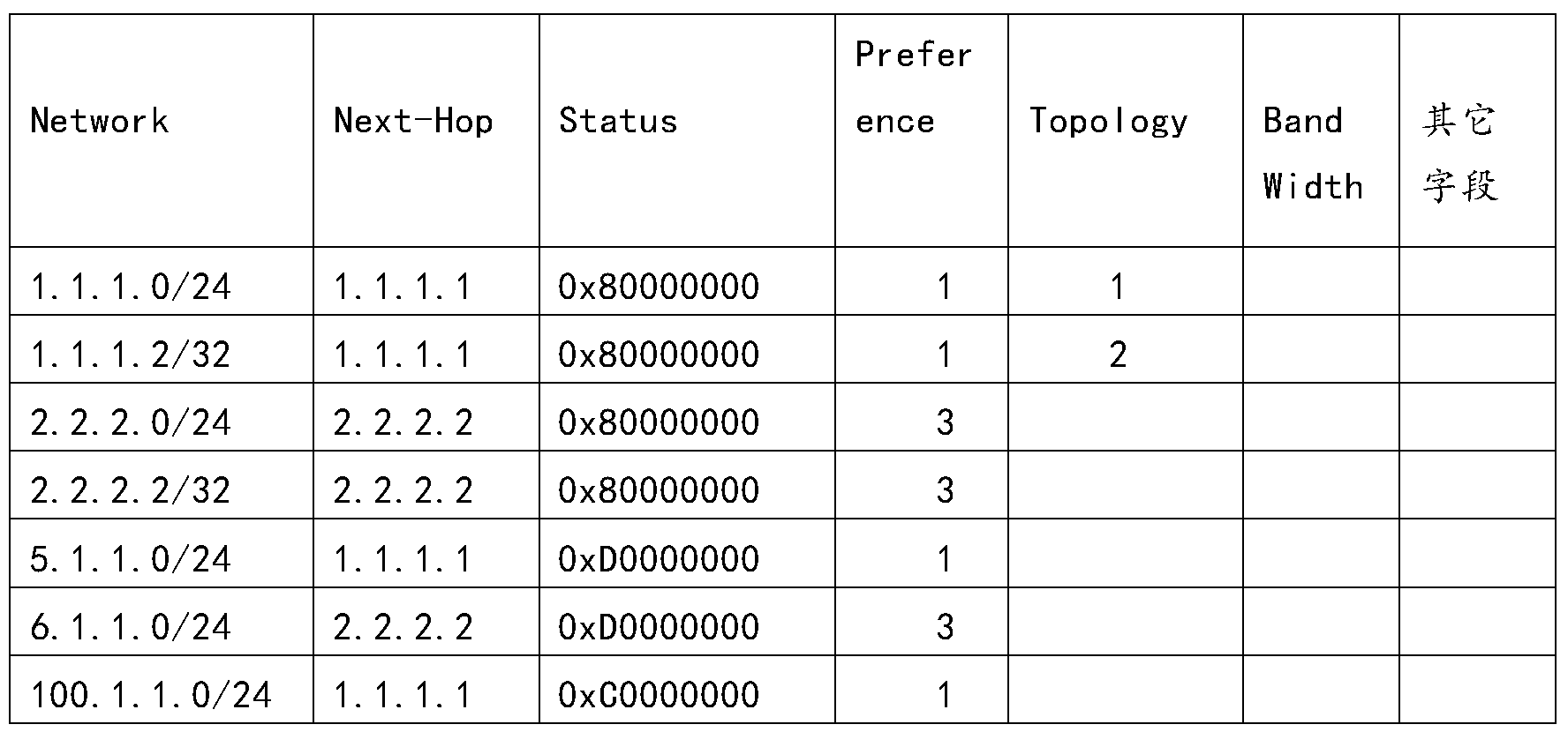
表3
如表3所示,所述CRP路由表包括多条CRP路由表项。对CRP路由表1中的各字段解释如下:
Network字段:表示路由前缀,通常使用目的地址/掩码(destination/Mask)表示,如果使用自然掩码,掩码可省略;
Next-Hop字段:表示下一跳地址;
Status字段:表示路由状态;
Preference字段:表示路由优先级;所述路由优先级用于指示所述CRP路由用于指导报文转发时的优先级。路由优先级的数值越小,表示路由优先级越高。Topology字段:表示网络设备的拓扑标识。指定相应的拓扑标识时,即按照指定的标识信息,使用相应的拓扑;未指定具体标识,即使用缺省的全局拓扑。
Band Width字段:表示下一跳的可用带宽。
其中,在控制器向网络设备发布CRP路由时,每条CRP路由表项信息至少要包括有路由前缀与下一跳地址的映射关系,其它的字段所包含的信息为可选携带的信息,可以缺省配置。当网络设备接收到报文以后,可以根据该CRP路由表的指导,将报文转发至下一跳网络设备。
在一个具体的实施方式中,上述的“Status”字段,可以由32位比特组成,每个比特代表一种路由状态。示例,“Status”字段的封装格式如表4所示:
| 0 | 1 | 2 | 3 | 4 | 5 | 6 | |||||||||
表4
V—Valid,1表示合法路由,0表示非法路由;
B—Best,1表示最优路由,0表示非最优路由;
A—Active,1表示激活路由,0表示非激活路由;
D—Download to FIB,1表示路由发送到FIB中,0表示路由没有发送到FIB。
对于“Status”的编码,示例说明如下:
0x80000000:只有V比特为1,表示路由是合法路由,非最优路由、非激活路由以及没有被发送到FIB。
0xD0000000:V、B、D三个比特位为1,A比特位为0,表示该路由是合法的、最优的、并且被发送到了FIB,但是该路由未被激活。
本申请仅以如上四个比特位为例,说明如何使用CRP路由表中Status字段,本领域技术人员可以理解,上述四个比特位中,0和1还可以表示相反的含义,比如:
V—Valid,0表示合法路由,1表示非法路由;
B—Best,0表示最优路由,1表示非最优路由;
A—Active,0表示激活路由,1表示非激活路由;
D—Download to FIB,0表示路由发送到转发表(forwarding information base,FIB)中,1表示路由没有发送到FIB。
也可以用其它数值来表示上述状态信息,本申请实施例对此不作具体限定。
本领域技术人员可以理解,Status字段还可以采用其它的封装格式进行封装,此处仅是示例性说明,不应理解为对本申请的限定。
需理解,表3中列出的多种信息仅是例举,并不对本申请构成限定。另外,虽然表3中列出了多种信息,但是本领域技术人员可以理解,所述CRP路由表项信息不必包括全部信息。或者,CRP路由表项信息也可以包括未在此处列出的其它字段所表示的信息,本申请实施例对此不作具体限定。
所述控制器通过收集各个网络设备的网元资源信息以及网络拓扑信息,来计算所述CRP路由,确定所述CRP路由表项信息。所述网元资源信息包括但不限于标签信息、接口资源信息、虚拟局域网(英文:Virtual Local Area Network,VLAN)信息以及隧道ID。所述网络拓扑信息是描述网络中节点和链路以及节点之间的连接关系的信息。控制器可以基于现有的各种拓扑收集协议,比如内部网关协议(英文:Interior Gateway Protocol,IGP),中间系统到中间系统(英文:intermediate system to intermediate system,ISIS)协议,开放式最短路径优先(Open Shortest Path First,OSPF)协议,来获得全网的拓扑信息。所述网络拓扑信息包括但不限于SDN中各个网络设备之间的路径信息。可选的,所述网络拓扑信息还包括各个网络设备之间的路径的权重信息等。
S212、控制器生成第三消息,用于发布CRP路由。
具体的,所述控制器生成第三消息,所述第三消息携带所述CRP路由表项信息,用于发布所述CRP路由。所述第三消息中包括第三标识信息,所述第三标识信息用于指示网络设备将所述CRP路由表项信息保存在该网络设备的CRP路由表中。
网络设备具体可以为传统路径计算单元(英文:Path Computation Element,PCE)网络中的传统路由器、交换机等路由转发设备,也可以是基于控制转发分离的SDN中的路由器或交换机等路由转发设备.网络设备可以具体为图1所示的R1至R5中任意一个。本申请实施例对此不做限定。
在一个具体的实施方式中,所述第三消息可以为第三BGP更新消息BGP UPDATE Message。所述第三BGP UPDATE Message中包括MP_REACH_NLRI属性字段。所述MP_REACH_NLRI属性字段中包括子地址族标识(英文:Subsequent Address Family
Identifier,SAFI)字段、网络层可达性信息NLRI字段和下一跳信息字段。所述SAFI字段指示该MP_REACH_NLRI属性字段是基于BGP同步地址族所支持的封装格式封装的,并承载所述第三标识信息。所述NLRI字段承载所述路由前缀。所述下一跳信息字段承载所述第三下一跳的地址。
其中该第三标识信息由该BGP同步地址族SAFI字段中SAFI的值所直接表示。
在本申请实施例中,可以在现有的BGP地址族中新增BGP同步地址族,并基于新增的BGP同步地址族所支持的封装格式,封装上述CRP路由表项信息。具体的,该BGP同步地址族新增的MP_REACH_NLRI的封装格式如图7所示。关于MP_REACH_NLRI中各字段的说明,参见上文中结合图7对MP_REACH_NLRI的说明,为了简洁,此处不再赘述。
其中,在一个可选的实施方式中,所述NLRI字段承载所述路由前缀具体包括:所述NLRI字段包括TLV字段,所述TLV字段的类型T字段表示所述TLV字段的类型为BGP路由同步类型,所述TLV字段的值V字段承载所述路由前缀。在NLRI字段包括的TLV字段中,例如,T字段值为2时,可以标识BGP路由同步(Route Entry Synchronization)类型。可选的,L字段值为16比特,即,2字节;V字段为L字段值所指示的长度的路由前缀。所述BGP同步类型包括所述BGP路由同步类型。
应理解,这里所列举的Type2类型为BGP路由同步类型仅为示例性说明,不应对本申请构成任何限定。本申请实施例不排除通过Type2来指示其他类型,或者用其他方式来指示BGP路由同步类型的可能。并且,本申请实施例对于NLRI Type的类型的数量也并未特别限定。
在另一个具体的实施方式中,所述第三消息为第三PCEP消息Message。所述第三PCEP Message包括消息类型Message-Type字段、路由对象Route object字段以及下一跳对象Next Hop object字段。所述Message-Type字段指示所述第三PCEP Message用于向所述网络设备发布所述CRP路由,并用于承载所述第三标识信息。所述Route object字段承载所述路由前缀。所述Next Hop object字段承载所述第三下一跳的地址。
其中,该第三标识信息可以由该Message-Type字段中Message-Type的值所直接表示。
在本申请实施例中,可以在现有的Message-Type中新增消息类型,用于指示所述第三PCEP Message。其中,在本申请实施例中,所述第三PCEP Message也可以称之为PCE实例化路由消息PCE-initiated Route Message。所述第三PCEP Message包括一个公共的消息头、所述路由对象以及所述下一跳对象。
所述第三PCEP Message中的所述公共的消息头以及所述下一跳对象的说明,分别参见上文中结合图5对所述公共消息头的说明以及结合图6对所述下一跳对象的相关说明,此处不再赘述。
作为示例,所述Route object的封装格式,如图9所示:
对于Route object的各字段的解释如下:
对象总类(Object-Class)的值待定义,由IANA管理;对象类型(Object-Type,OT)值为1;Object-Class和Object-Type两个一起唯一确定所述Route object。保
留(Res)字段发送时填充为0,收到时忽略;
处理规则标记(P)字段和忽略标记(I)字段在本Route object中未使用,设置为0。
对象长度(Object Length)的值为Route object的长度,包括对象头。
所述Route object包括一个或多个子对象Sub-object,子对象为可变长度,子对象字段的长度由对象长度字段所标识的长度决定。
在一个具体的实施方式中,Route object中Sub-object为IPv4前缀子对象,携带IPv4地址前缀,作为示例,可以使用图10所示的封装格式进行封装,如图10所示:
IPv4 prefix子对象的各字段解释如下:
子对象的属性(L)字段:在所述Route object中,L位暂未使用,设置为0。
子对象类型(Type)字段:取值为0x01,表示IPv4地址。对于Type的取值,仅为示例性说明,不作具体限定。
子对象长度(Length)字段:子对象的长度。
IPv4地址字段:IPv4地址。这个地址被看作是基于下列的前缀长度(Prefix Length)的前缀。超出前缀的位在接收时被忽略,并且在传输时被设置为0。
前缀长度(Prefix length)字段:IPv4前缀的长度。
填充(Padding)字段:传输时设置为0,接收时忽略。
一个IPv4前缀对象的内容是一个4字节的IPv4地址,一个1字节的前缀长度和一个1字节的填充域。这个子对象所表示的抽象节点是一系列有相同IP地址前缀的节点。其中,前缀长度为32表示是一个单个IPv4节点。
在另一个具体的实施方式中,所述Route object中Sub-object为IPv6前缀子对象,携带IPv6地址前缀。作为示例,可以使用图11所示的封装格式进行封装,如图10所示:
IPv6 prefix子对象的各字段解释如下:
子对象的属性(L)字段:在所述Route object中,L位暂未使用,设置为0。
子对象类型(Type)字段:取值为0x02,表示IPv6地址。
子对象长度(Length)字段:子对象的长度。
IPv6地址字段:IPv6地址。这个地址被看作是基于下列的前缀长度(Prefix Length)的前缀。超出前缀的位在接收时被忽略,并且在传输时被设置为0。
前缀长度(Prefix length)字段:IPv6前缀的长度。
填充(Padding)字段:传输时设置为0,接收时忽略。
一个IPv6前缀子对象的内容是一个16字节的IPv6地址,一个1字节的前缀长度和一个1字节的填充域。这种子对象所表示的抽象节点是一系列属于相同IP前缀的节点。其中,值为128的前缀长度表示了一个单个的IPv6节点。
应理解,这里所列举的各子段的取值和/或长度仅为示例性说明,不应对本申请构成任何限定。本申请实施例不排除Object-Type字段取值为其它值的可能。
应理解,这里所列举的Route object的封装格式,仅为示例性说明,本申请实施例对于Route object的封装格式以及Route object中相关字段的取值,不作具体限
定。本申请实施例不排除采用其它的封装格式对Route object进行封装的可能。
S213、控制器向网络设备发送所述第三消息。
具体的,所述控制器向所述网络设备发送所述第三消息,以便于所述网络设备根据所述第三标识信息将所述CRP路由表项信息保存在所述网络设备的CRP路由表中,根据所述CRP路由表指导报文转发。
可选的,所述控制器自身保存有CRP路由表,控制器确定所述CRP路由表项信息后,在所述控制器保存的CRP路由表中保存所述CRP路由表项信息。
S214、网络设备接收所述第三消息。
S215、网络设备将所述CRP路由表项信息保存在所述网络设备的CRP路由表中。
具体的,网络设备接收到所述第三消息后,根据所述第三消息中携带的第三标识信息,识别出需要将所述第三消息中携带的所述CRP路由表项信息保存到所述网络设备的CRP路由表后,将所述CRP路由表项信息保存在所述网络设备的CRP路由表中,进而可以根据所述CRP路由表指导报文转发。
在一个具体的实施方式中,网络设备接收到所述第三消息后,以所述第三消息中携带的路由前缀为关键字,在所述CRP路由表中进行表项查找,如果命中相应的表项,则使用所述CRP路由表项信息更新所找到的表项中的相应信息。如果没有命中相应的表项,则创建一条CRP路由表项,将所述CRP路由表项信息保存到新创建的CRP路由表项中。
通过上述技术方案,在控制器和转发设备之间运行CRP协议,转发设备上创建单独的CRP路由表,用于保存控制器发送的CRP路由表项信息。CRP路由表中优选的路由被添加到路由管理(Routing Management,RM)路由信息表(Routing Informatin Base,RIB)中,使得RM模块可以在CRP路由、ISIS路由,BGP路由,OSPF路由等通过不同的路由协议所生成的路由之间进行路由选择。并且由于该控制器发布的CRP路由与转发设备之间的路由协议发布的路由保存在不同的路由表中,从而使得与所述CRP路由相关的路由策略不会影响到转发设备间的路由协议中路由所体现的路由策略的相关应用。
可选的,所述CRP路由表项信息还包括:路由同步属性信息,所述路由同步属性信息用于所述控制器发送路由前缀时携带通过所述控制器制定的路由属性信息。
所述路由同步属性信息包括但不限于:所述路由优先级、所述拓扑以及下一跳的属性信息。
所述下一跳的属性信息包括至少一种下一跳的属性信息类型。所述下一跳的属性信息类型包括但不限于:下一跳接入的类型,比如:IP网络、VXLAN等;可用带宽(Band Width)以及负载均衡比例(Weight)等。
在一个具体的实施方式中,在上述以BGP UPDATE Message承载所述CRP路由表项信息的实施例中,所述第三BGP UPDATE Message还包括路由同步Route Synchronization属性Attribute字段。所述Route Synchronization Attribute字段承载所述路由同步属性信息。可选的,所述Route Synchronization Attribute字段包括至少一个子TLV字段,每种路由同步属性信息类型与所述至少一个子TLV字段中的一个子TLV字段对应。每个子TLV字段都包括T字段、L字段和V字段,所述T
字段表示所述路由同步属性信息类型中的任意一种,所述V字段指示基于所对应的路由同步属性信息类型所确定的内容。所述路由同步属性信息的类型包括所述路由优先级。
在另一个具体的实施方式中,在上述以PCEP Message承载所述CRP路由表项信息的实施例中,所述第三PCEP Message还包括PCEP路由属性对象Route Attribute object字段,所述PCEP Route Attribute object字段承载所述路由同步属性信息。可选的,所述PCEP Route Attribute object字段包括至少一个子TLV字段,每种路由同步属性信息类型与所述至少一个子TLV字段中的一个子TLV字段对应,每个子TLV字段都包括T字段、L字段和V字段,所述T字段表示所述路由同步属性信息类型中的任意一种,所述V字段指示基于所对应的路由同步属性信息的类型所确定的内容。所述路由同步属性信息的类型包括所述路由优先级。
上述两种携带所述路由同步属性信息的实施方式中,TLV的具体内容或取值可以根据各消息的具体情况设定,可以采用相同的设置方式,也可以采用不同的设置方式,本申请对此不做限定。
在一个具体的实施例中,比如,T字段为1时,可以标识路由优先级类型;L字段为2字节;V字段为具体路由优先级的数值,比如3。再比如,T字段为2时,可以标识拓扑类型;L字段为2字节;V字段为具体的拓扑标识,比如1。T字段为3时,可以标识下一跳可用带宽类型;L字段为2字节;V字段为具体的可用带宽的数值,比如20000kbit/sec。再比如,T字段为4时,可以标识下一跳负载均衡比例类型;L字段为2字节;V字段为具体的负载均衡比例,比如50%,标识下一跳参与50%的负载分担。
应理解,上述列举的路由同步属性信息的类型仅为示例性说明,不应对本申请构成任何限定。用于承载路由同步属性信息的字段并不限于上述Route Synchronization Attribute字段或Route Attribute object字段,还可以通过其他现有的或新增的字段来承载,本申请对此并未特别限定。并且,这里所列举的Type1类型为路由优先级类型,Type2类型为拓扑类型,Type3为下一跳可用带宽类型,Type4为下一跳负载均衡比例类型,同样不应对本申请构成任何限定。本申请实施例不排除通过Type1至Type4来指示其他类型,或者用其他方式来指示路由优先级类型、拓扑类型、下一跳可用带宽类型以及下一跳负载均衡比例类型的可能。并且,本申请实施例对于路由同步属性信息的类型的数量也并未特别限定。
可选的,在本申请中,还可以单独采用下一跳属性字段来携带所述下一跳的属性信息。
在一个具体的实施方式中,在上述以BGP UPDATE Message承载所述CRP路由表项信息的实施例中,所述第三BGP UPDATE Message还包括下一跳同步属性Next Hop Attribute字段,所述Next Hop Attribute字段承载所述第三下一跳的属性信息。可选的,所述Next Hop Synchronization Attribute字段包括至少一个子TLV字段,每种下一跳的属性信息类型与所述至少一个子TLV字段中的一个子TLV字段对应。每个子TLV字段都包括T字段、L字段和V字段。所述T字段表示所述下一跳的属性信息的类型中的任意一种。所述V字段指示基于所对应的下一跳的属性信息类型所确定的内容。
在另一个具体的实施方式中,在上述以PCEP Message承载所述CRP路由表项信息的实施例中,所述第三PCEP Message还包括PCEP下一跳属性对象Next Hop Attribute object字段。所述PCEP Next Hop Attribute object字段承载所述第三下一跳的属性信息。可选的,所述PCEP Next Hop Attribute object字段包括至少一个子TLV字段,每种下一跳的属性信息类型与所述至少一个子TLV字段中的一个子TLV字段对应。每个子TLV字段都包括T字段、L字段和V字段。所述T字段表示所述下一跳的属性信息类型中的任意一种。所述V字段指示基于所对应的下一跳的属性信息类型所确定的内容。
上述两种单独采用下一跳属性字段来携带所述下一跳的属性信息的实施方式中,所述TLV的具体内容或取值可以根据各消息的具体情况设定,可以采用相同的设置方式,也可以采用不同的设置方式,本申请对此不做限定。在本申请实施例中,比如,T字段为1时,可以标识可用带宽类型;L字段为2字节;V字段为具体的可用带宽的数值,比如20000kbit/sec。再比如,T字段为2时,可以标识负载均衡比例类型;L字段为2字节;V字段为具体的负载均衡比例,比如50%,标识下一跳参与50%的负载分担。
应理解,上述列举的下一跳的属性信息的类型仅为示例性说明,不应对本申请构成任何限定。用于承载下一跳的属性信息的字段并不限于上述Next Hop Attribute字段或Next Hop Attribute object字段,还可以通过其他现有的或新增的字段来承载,本申请对此并未特别限定。并且,这里所列举的Type1类型为可用带宽类型,Type2类型为负载均衡比例类型,同样不应对本申请构成任何限定。本申请实施例不排除通过Type1和Type2来指示其他类型,或者用其他方式来指示可用带宽类型和负载均衡类型的可能。并且,本申请实施例对于Next Hop Synchronization Attribute的类型的数量也并未特别限定。
在本申请中,通过在CRP表项信息中携带路由优先级,可以实现对CRP路由优先级的灵活设置,例如,将CRP路由设置为优选路由,从而实现使用控制器发布的路由对流量进行控制的目的。对于后续针对路由的各种复杂的策略控制,通过升级控制器即可完成,无需像现有路由策略,比如BGP路由策略,需要所有设备都实现复杂的策略。因而,使得流量调控更为简单,灵活。另外,在某些应用场景下,客户认为内部部署的IGP路由受信任应该被优选,而外部路由不受信任不应被优选,则也可以将所述CRP路由的优先级设置为低于ISIS路由以及OSPF路由的优先级。由此可见,通过对CRP路由的优先级进行设定,可以满足客户的不同需求。
进一步的,通过CRP路由表项信息中携带所述下一跳的属性信息,使得网络设备可以在所述CRP路由表中,获取所述下一跳的属性信息,并将所述下一跳的属性信息发送到FIB中,指导报文转发。
需要说明的是,当所述CRP路由表项信息包括所述路由同步属性信息时,在所述网络设备接收到所述第三消息后,根据所述第三标识信息的指示,将所述路由同步属性信息保存到所述CRP路由表中。具体地,当网络设备接收所述第三消息,以第三消息中携带的路由前缀为关键值,进行CRP路由表查找,命中相应的表项,则使用所述路由同步属性信息更新所命中的表项中的相应信息。如果没有命中相应的表项,则创
建一条新的表项,将所述路由同步属性信息保存到所述新的表项中。
进一步的,在所述网络设备接收到所述第三消息后,根据所述第三标识信息的指示,将所述第三下一跳的属性信息保存到本地的下一跳表中。具体地,所述网络设备除了将所述第三下一跳的属性信息保存到所述CRP路由表以外,还以所述第三消息中携带的第三下一跳的地址为关键值,在自身保持的下一跳表中进行查找,如果命中相应的表项,则使用所述第三下一跳的属性信息更新所找到的表项中的相应信息,如果没有命中表项,则创建一条新的表项,用于保存所述第三下一跳的地址和所述第三下一跳的属性信息。
需要说明的是,当所述第三消息中未携带所述路由同步属性信息时,则网络设备可以按照现有的规则以缺省值处理,例如:设置协议间选路优先级为1,不限制下一跳的带宽,不设置下一跳的负载均衡比例,不指定下一跳的类型。
可选的,所述方法200还可以包括S216-S218:
S216、网络设备生成第四消息。
所述第四消息携带路由状态报告信息,所述路由状态报告信息包括所述路由前缀和所述CRP路由的状态信息的映射关系。
所述CRP路由的状态信息包括但不限于:路由的状态,例如路由是否合法,是否被优选,是否被发送到FIB中等;路由的存活时间;下一跳的状态,例如下一跳是否合法,是否被使用等;下一跳带宽占用比例;下一跳丢包率;下一跳发包延时;下一跳存活时间。其中与下一跳相关的状态信息(例如下一跳的状态,例如下一跳是否合法,是否被使用等,下一跳带宽占用比例,下一跳丢包率,下一跳发包延时,以及下一跳存活时间)也可以放在以下步骤219中描述的下一跳状态报告信息中携带。具体可以参见下面说明。
在一个具体的实施方式中,所述第四消息为第四BGP UPDATE Message,所述第四BGP UPDATE Message包括MP_REACH_NLRI属性字段和路由状态报告属性Route Status Report Attribute字段。所述MP_REACH_NLRI属性字段中包括NLRI字段。所述NLRI字段用于承载所述路由前缀。所述Route Status Report Attribute字段用于承载所述CRP路由的状态信息。可选的,所述Route Status Report Attribute字段包括至少一个子TLV字段。每个所述CRP路由的状态信息的类型与所述至少一个子TLV字段对应。每个子TLV字段都包括T字段、L字段和V字段。所述T字段表示所述CRP路由的状态信息类型中的任意一种。所述V字段指示基于所对应的CRP路由的状态信息类型所确定的内容。
在另一个具体的实施方式中,所述第四消息为第四PCEP Message,所述第四PCEP Message包括消息类型Message-Type字段、路由对象Route object字段以及路由状态报告属性对象Route Status Report Attribute object字段。所述Message-Type字段指示所述第四PCEP Message用于向所述控制器发送所述路由状态报告信息。所述Route object字段承载所述路由前缀。所述Route Status Report Attribute object字段承载所述CRP路由的状态信息。可选的,所述Route Status Report Attribute object字段包括至少一个子TLV字段。每个所述CRP路由的状态信息的类型与所述至少一个子TLV字段对应。每个子TLV字段都包括T字段、L字段和V字段。所述T字
段表示所述CRP路由的状态信息类型中的任意一种。所述V字段指示基于所对应的CRP路由的状态信息类型所确定的内容。
在本申请实施例中,比如,T字段为1是,可以标识所述CRP路由的路由当前状态Status类型;L字段为2字节;所述V字段指示CRP路由的路由当前状态Status的具体内容,比如当前路由是否合法,是否优选,是否激活等。
应理解,这里所列举的Type1类型为所述CRP路由的路由当前状态Status类型仅为示例性说明,不应对本申请构成任何限定。本申请实施例不排除通过Type1来指示其他类型,或者用其他方式来指示所述CRP路由的路由当前状态Status类型的可能。并且,本申请实施例对于TLV Type的类型的数量也并未特别限定。
在一个具体的实施方式中,所述网络设备在本地保存有路由状态报告信息表,用于保存所述路由状态报告信息。作为示例,所述路由状态报告信息表如表5所示:

表5
如表5所示,路由状态报告信息表中包括多个字段,对于各字段解释如下:
Network字段:表示所述路由前缀;
Next-Hop字段:表示下一跳地址;
Status字段:表示路由状态;
Age字段:表示当前路由的存活时间;
Band Width字段:表示下一跳的可用带宽。
对于Status字段的封装格式以及相关说明参见表4以及对表4进行的相关说明,此处不再赘述。
需理解,表5中列出的多种状态信息仅是例举,并不对本申请构成限定。另外,虽然表5中列出了多种状态信息,但是本领域技术人员可以理解,路由状态报告信息可以包括所述多种状态信息中的一种或多种,而不必包括全部状态信息。或者,路由状态报告信息也可以仅包括未在此处列出的其它字段所表示状态信息,本申请实施例对此不作具体限定。
S217、网络设备向控制器发送第四消息。
在一个具体的实施方式中,网络设备周期性上报所述CRP路由的状态信息。例如,在系统稳定运行的情况下,通过配置或者协商,180秒上报一次,网络设备将流量统计信息以及带宽使用信息等路由的状态信息上报给控制器。
在另一个具体的实施方式中,网络设备实时上报所述路由的状态信息。例如,在
系统发生重要事件时,比如路由信息所对应的表项由优选变为不再优选,或者路由表项迭代隧道不成功等情况发生时,网络设备将所述路由的状态信息上报给控制器。
S218、控制器接收所述第四消息。
控制器根据接收到的路由状态报告信息,更新所述路由前缀的统计信息,作为重新计算所述CRP路由的依据。
通过以上技术方案,控制器可以定期、实时获取转发设备上报的路由状态信息,能够实时了解转发设备的状态,作为调整路由的依据,提高了流量调控的可靠性以及实时性。
可选的,所述方法200还可以包括S219-S221。
S219、网络设备生成第五消息。
所述第五消息携带下一跳状态报告信息,所述下一跳状态报告信息包括所述网络设备的第四下一跳的地址和该第四下一跳的状态信息的映射关系。
所述下一跳状态报告信息包括但不限于:下一跳的状态,例如下一跳是否合法,是否被使用等;下一跳带宽占用比例;下一跳丢包率;下一跳发包延时;下一跳存活时间。
需要说明的是,所述第四下一跳与所述第三下一跳可以是相同的下一跳;或者所述第四下一跳与所述第一下一跳可以是相同的下一跳;或者所述第四下一跳与所述第二下一跳可以是相同的下一跳;或者,所述第四下一跳、所述第三下一跳、所述第二下一跳与所述第一下一跳均可以是相同的下一跳;或者所述第四下一跳、所述第三下一跳、所述第二下一跳与所述第一下一跳均可以是不同的下一跳。
在一个具体的实施方式中,所述第五消息为第五BGP UPDATE Message。所述第五BGP UPDATE Message包括多协议可达网络层可达信息MP_REACH_NLRI属性字段和下一跳状态报告属性Next Hop Status Report Attribute字段。所述MP_REACH_NLRI属性字段中包括网络层可达信息NLRI字段,所述NLRI字段用于承载所述第四下一跳的地址。所述Next Hop Status Report Attribute字段用于承载所述第四下一跳的状态信息。可选的,所述Next Hop Status Report Attribute字段包括至少一个子TLV字段,每种下一跳的状态信息类型与所述至少一个子TLV字段中的一个子TLV字段对应。每个子TLV字段都包括T字段、L字段和V字段。所述T字段表示所述下一跳的状态信息类型中的任意一种。所述V字段指示基于所对应的下一跳的状态信息类型所确定的内容。
在另一个具体的实施方式中,所述第五消息为第五PCEP Message。所述第五PCEP Message包括消息类型Message-Type字段、下一跳对象Next Hop object字段以及下一跳状态报告属性对象Next Hop Status Report Attribute object字段。所述Message-Type字段指示所述第五PCEP Message用于向所述控制器发送所述下一跳状态报告信息。所述Next Hop object字段承载所述第四下一跳的地址。所述Next Hop Status Report Attribute object字段承载所述第四下一跳的状态信息。可选的,所述Next Hop Status Report Attribute object字段包括至少一个子TLV字段,每种下一跳的状态信息类型与所述至少一个子TLV字段中的一个子TLV字段对应。每个子TLV字段都包括T字段、L字段和V字段。所述T字段表示所述下一跳的状态信息类型
中的任意一种。所述V字段指示基于所对应的下一跳的状态信息类型所确定的内容。
在本申请实施例中,比如,T字段为1是,可以标识下一跳当前状态Status类型;L字段为2字节;所述V字段指示下一跳状态Status的具体内容,比如当前路由是否合法,是否优选,是否激活等。
应理解,这里所列举的Type1类型为所述下一跳当前状态Status类型仅为示例性说明,不应对本申请构成任何限定。本申请实施例不排除通过Type1来指示其他类型,或者用其他方式来指示所述下一跳当前状态Status类型的可能。并且,本申请实施例对于TLV Type的类型的数量也并未特别限定。
在另一个具体的实施方式中,所述网络设备在本地保存有下一跳状态报告信息表,用于保存下一跳状态报告信息。作为示例,所述下一跳状态报告信息表如表6所示:

表6
如表6所示,下一跳状态报告信息表包括多个字段,对各字段解释如下:
Next-Hop字段:表示下一跳的地址;
Type字段:表示下一跳的类型;
Status字段:表示下一跳的状态;
Band Width字段:表示下一跳的可用带宽;
Weight字段:表示下一跳的负载均衡比例;
Loss字段:表示丢包的报文数;
Delay字段:表示时延,单位是微秒。
对于Status字段的封装格式以及相关说明参见表2以及对表2进行的相关说明,此处不再赘述。
需理解,表6中列出的多种状态信息仅是例举,并不对本申请构成限定。另外,虽然表6中列出了多种状态信息,但是本领域技术人员可以理解,下一跳状态报告信息可以包括所述多种状态信息中的一种或多种,而不必包括全部状态信息。或者,下一跳状态报告信息也可以仅包括未在此处列出的其它字段所表示的其它状态信息,本申请实施例对此不作具体限定。
S220、网络设备向控制器发送所述第五消息。
在一个具体的实施方式中,网络设备周期性上报所述下一跳状态信息。例如,在系统稳定运行的情况下,通过配置或者协商,180秒上报一次,网络设备将流量统计信息以及带宽使用信息等下一跳的状态信息上报给控制器。
在另一个具体的实施方式中,网络设备实时上报所述下一跳的状态信息。例如,在系统发生重要事件时,比如下一跳信息所对应的表项由可达变为不可达,或者该下
一跳所对应的出口链路的带宽使用率超过了阈值(例如90%)等情况发生时,网络设备将所述下一跳的状态信息上报给控制器。
S221、控制器接收所述第五消息。
控制器根据接收到的下一跳状态报告信息,更新所述网络设备的下一跳信息的统计信息,作为重新计算所述下一跳信息的依据。
通过以上技术方案,控制器可以定期、实时获取转发设备上报的下一跳状态信息,能够实时了解转发设备的状态,作为计算,调整下一跳的依据,提高了流量调控的可靠性以及实时性。
需要说明的是,本申请对S201-S205、S206-S210、S211-S215、S216-S218以及S219-S221的执行顺序不作具体限定。例如,S206-S210可以在S201-S205之前执行,也可以在S201-S205之后执行。S206-S210可以在S211-S215之前执行,也可以在S211-S215之后执行。并且,S201-S205、S206-S210、S211-S215、S216-S218以及S219-S221均可以单独执行。
以上,结合图1至图11详细说明了根据本申请实施例提供的管理信息的方法。以下,结合图12-图15详细说明根据本申请实施例提供的管理信息同步的装置和系统。
图12是根据本申请一实施例的控制器400的示意图。该控制器400可以,是图1中所示的控制器110,用于执行图2所示的方法。如图12所示,该控制器400包括:处理模块401和发送模块402。
该处理模块401,用于生成第一消息,所述第一消息携带网络设备的第一下一跳的地址,所述第一消息中包括第一标识信息。所述第一标识信息用于指示所述网络设备在所述网络设备保存的下一跳中删除与所述第一下一跳的地址对应的第一下一跳的表项第一下一跳。
该发送模块402,用于向所述网络设备发送所述第一消息,以便所述网络设备根据所述第一标识信息的指示删除所述第一下一跳的表项。
在一个具体的实施方式中,所述第一消息为第一BGP UPDATE Message。第一BGP UPDATE Message具体采用何种消息格式或字段格式(如采用哪些字段或扩展字段),可以参考上述方法实施例中对应部分的描述,此处不再赘述。
在另一个具体的实施方式中,所述第一消息为第一PCEP Message。第一PCEP Message具体采用何种消息格式或字段格式(如采用哪些字段或扩展字段),可以参考上述方法实施例中对应部分的描述,此处不再赘述。
。
可见,通过接收控制器发送的携带有第一下一跳的地址的第一消息,根据第一消息中携带的第一标识信息,网络设备在单独保存的下一跳表中删除与所述第一下一跳的地址对应的第一下跳表项,不必再捆绑路由前缀以及通过大量撤销路由消息来删除某个不可用的下一跳,节省了网络资源。并且,当存在多条路由表项同时对应同一个下一跳时,通过删除该多条路由表项所对应的下一跳,进而能够删除使用该下一跳的多条路由表项。因此,控制器和网络设备设备之间只需要发送一条消息,即可实现快速,批量删除路由表项的目的。因而大大减少了控制器和转发设备之间交互消息的数量,节省了系统资源,提高了业务处理效率。
可选的,所述处理模块401,还用于生成第二消息,所述第二消息携带所述网络设备的第二下一跳的表项信息,所述第二下一跳的表项信息包括所述网络设备的第二下一跳的地址与第二下一跳的属性信息的映射关系。所述第二消息中包括第二标识信息,所述第二标识信息用于指示所述网络设备将所述第二下一跳的表项信息保存在所述网络设备的下一跳表中。
所述发送模块402,还用于向所述网络设备发送所述第二消息,以便于所述网络设备根据所述第二标识信息将所述第二下一跳的表项信息保存在所述网络设备的下一跳表中。
在一个具体的实施中,所述第二消息为第二BGP UPDATE Message。第二BGP UPDATE Message具体采用何种消息格式或字段格式(如采用哪些字段或扩展字段),可以参考上述方法实施例中对应部分的描述,此处不再赘述。
在另一个具体的实施方式中,所述第二消息为第二PCEP Message。第二PCEP Message具体采用何种消息格式或字段格式(如采用哪些字段或扩展字段),可以参考上述方法实施例中对应部分的描述,此处不再赘述。
因此,控制器可以向网络设备单独发送下一跳信息,实现了控制器对网络设备的下一跳信息进行单独管理。单独管理包括单独创建或者更新下一跳信息,而不必绑定路由前缀。上述方案使得控制器对于网络设备的下一跳管理更加灵活;并且有效的节省控制器与网络设备的信息交互中,由于携带所述路由前缀所占用的系统资源;网络设备需要解析的信息减少,也提高了网络设备的业务处理效率。
进一步的,控制器向网络设备独立发送下一跳信息时,携带控制器定制的下一跳的属性信息,使得网络设备可以在下一跳表中,获取所述所述下一跳的属性信息,并将所述下一跳的属性信息发送到FIB表中,用于指导报文转发。
可选的,所述处理模块401,还用于确定控制路由协议CRP路由表项信息,所述CRP路由表项信息包括有路由前缀和第三下一跳的地址的映射关系。所述处理模块401,还用于生成第三消息,所述第三消息携带所述CRP路由表项信息,用于发布CRP路由。所述第三消息中包括第三标识信息,所述第三标识信息用于指示网络设备将所述CRP路由表项信息保存在所述网络设备的CRP路由表中。
所述发送模块402,还用于向所述网络设备发送所述第三消息,以便于所述网络设备根据所述第三标识信息将所述CRP路由表项信息保存在所述CRP路由表中,并根据所述CRP路由表指导报文转发。
需要说明的是,该第三下一跳的地址可以是与所述第一下一跳相同的地址,也可以是与所述第二下一跳相同的地址,当然,也可以是与所述第一下一跳以及所述第二下一跳都不相同的地址。
在一个具体的实施方式中,所述第三消息为第三边界网关协议BGP更新消息UPDATE Message。第三BGP UPDATE Message具体采用何种消息格式或字段格式(如采用哪些字段或扩展字段),可以参考上述方法实施例中对应部分的描述,此处不再赘述。
在另一个具体的实施方式中,所述第三消息为第三PCEP Message。第三PCEP Message具体采用何种消息格式或字段格式(如采用哪些字段或扩展字段),可以参考上述方法实施例中对应部分的描述,此处不再赘述。
因此,根据本申请实施例的控制器,通过在控制器和网络设备之间运行CRP协议,网络设备上创建单独的CRP路由表,用于保存控制器发送的CRP路由表项信息。CRP路由表中优选的路由被添加到RM RIB中,使得RM模块可以在CRP路由、ISIS路由,BGP路由,OSPF路由等通过不同的路由协议所生成的路由之间进行路由选择,并且由于该控制器发布的CRP路由与转发设备之间的路由协议发布的路由保存在不同的路由表中,从而使得CRP路由相关的路由策略不会影响到转发设备间的路由协议中路由所体现的路由策略的相关应用。
可选的,所述CRP路由表项信息还包括:路由同步属性信息,所述路由同步属性信息用于所述控制器发送路由前缀时携带通过所述控制器制定的路由属性信息。
所述路由同步属性包括但不限于:所述路由优先级、所述拓扑以及下一跳的属性信息。
所述第一下一跳的属性信息包括以下一种或多种下一跳的属性信息的类型:带宽、负载均衡比例和下一跳的类型。
在一个具体的实施方式中,在上述以BGP UPDATE Message承载所述CRP路由表项信息的实施例中,所述第三BGP UPDATE Message还包括路由同步Route Synchronization属性Attribute字段,用于承载所述路由同步属性。具体的携带方式,即采用什么消息格式和字段格式等,可以参考上述方法实施例中对应部分的描述,此处不再赘述。
在另一个具体的实施方式中,在上述以PCEP Message承载所述CRP路由表项信息的实施例中,所述第三PCEP Message还包括PCEP路由属性对象Route Attribute object字段,用于承载所述路由同步属性。具体的携带方式,即采用什么消息格式和字段格式等,可以参考上述方法实施例中对应部分的描述,此处不再赘述。
需要说明的是,当所述第三消息中未携带所述路由同步属性信息时,则网络设备可以按照现有的规则以缺省值处理,例如:设置协议间选路优先级为1,不限制下一跳的带宽,不设置下一跳的负载均衡比例,不指定下一跳的类型。
通过在路由属性信息中携带路由优先级,可以实现对CRP路由优先级的灵活设置,例如,将CRP路由设置为优选路由,从而实现使用控制器发布的路由对流量进行控制的目的。对于后续针对路由的各种复杂的策略控制,通过升级控制器即可完成,无需像现有路由策略,比如BGP路由策略,需要所有设备都实现复杂的策略。因而,使得流量调控更为简单,灵活。另外,在某些应用场景下,客户认为内部部署的IGP路由受信任应该被优选,而外部路由不受信任不应被优选,则也可以将所述CRP路由的优先级设置为低于ISIS路由以及OSPF路由的优先级。由此可见,通过对CRP路由的优先级进行设定,可以满足客户的不同需求。
可选的,在本申请中,还可以单独采用下一跳属性字段来携带所述下一跳的属性信息。
在一个具体的实施方式中,在上述以BGP UPDATE Message承载所述CRP路由表项信息的实施例中,所述第三BGP UPDATE Message还包括下一跳属性Next HopAttribute字段,用于承载所述下一跳的属性信息。具体的携带方式,即采用什么消息格式和字段格式等,可以参考上述方法实施例中对应部分的描述,此处不再赘述。
在另一个具体的实施方式中,在上述以PCEP Message承载所述CRP路由表项信息的实施例中,所述第三PCEP Message还包括PCEP下一跳属性对象Next Hop Attribute object字段,具体的携带方式,即采用什么消息格式和字段格式等,可以参考上述方法实施例中对应部分的描述,此处不再赘述。
通过CRP路由表项信息中携带所述下一跳的属性信息,使得网络设备可以在所述CRP路由表中,获取所述下一跳的属性信息,并将所述下一跳的属性信息发送到FIB中,指导报文转发。
在一个具体的实施方式中,所述控制器400还包括接收模块403。所述接收模块403用于接收所述网络设备发送的第四消息;所述第四消息携带路由状态报告信息,所述路由状态报告信息包括所述路由前缀与所述CRP路由的状态信息的映射关系。
所述处理模块401还用于根据接收到的所述路由状态报告信息,更新所述路由前缀的统计信息,作为重新计算所述CRP路由的依据。
所述CRP路由的状态信息包括但不限于:路由的状态,例如路由是否合法,是否被优选,是否被发送到FIB中等;路由的存活时间;下一跳的状态,例如下一跳是否合法,是否被使用等;下一跳带宽占用比例;下一跳丢包率;下一跳发包延时;下一跳存活时间。
因此,控制器可以定期、实时获取网络设备上报的路由状态信息,能够实时了解网络设备路由的状态,作为调整路由的依据,提高了流量调控的可靠性以及实时性。
可选的,所述接收模块403还用于接收所述网络设备发送的第五消息;所述第五消息携带下一跳状态报告信息,所述下一跳状态报告信息包括所述网络设备的第四下一跳的地址和所述第四下一跳的状态信息的映射关系。
需要说明的是,该第四下一跳的地址可以是与所述第一下一跳相同的地址,也可以是与所述第二下一跳相同的地址,也可以是与所述第三下一跳相同的地址,当然,也可以是与所述第一下一跳至所述第三下一跳中任意一个都不相同的地址。
所述处理模块401还用于根据接收到的所述下一跳状态报告信息,更新所述第四下一跳的统计信息,作为重新计算所述网络设备的下一跳的依据。
所述下一跳状态报告信息包括但不限于:下一跳的状态,例如下一跳是否合法,是否被使用等;下一跳带宽占用比例;下一跳丢包率;下一跳发包延时;下一跳存活时间。
因此,控制器可以定期、实时获取转发设备上报的下一跳状态信息,能够实时了解转发设备的状态,作为计算,调整下一跳的依据,提高了流量调控的可靠性以及实时性。
根据本申请实施例的控制器400可对应于根据本申请实施例中用于管理信息的方法200中的控制器,并且,该控制器400中的各模块和上述其它操作和/或功能分别为了实现图2中的方法200的相应流程,为了简洁,在此不再赘述。
图13是根据本申请实施例的网络设备500的示意图。该网络设备500可以是图所示的网络设备120,可以用于执行图2所示的方法。如图13所示,该网络设备500包括:接收模块501和处理模块502。
所述接收模块501用于接收控制器发送的第一消息,所述第一消息携带所述网络设备的第一下一跳的地址,所述第一消息中包括第一标识信息。
所述处理模块502用于根据所述第一标识信息的指示,在所述网络设备保存的下一跳表中删除与所述第一下一跳的地址对应的第一下一跳的表项。
具体地,所述处理模块502根据所述第一标识信息的指示,以所述第一下一跳的地址为关键字,查找所述下一跳表,命中所述第一下一跳的表项,将所述第一下一跳的表项删除。
在命中所述第一下一跳的表项之后,删除所述第一下一跳的表项之前,所述处理模块还用于通知使用所述第一下一跳的地址的路由表项,该第一下一跳的地址不可用,并删除与所述第一下一跳的地址关联的所述路由表项。
因此,当存在多条路由表项同时对应同一个下一跳时,通过删除该多条路由表项所对应的下一跳,使得使用该下一跳的多条路由表项随之自动删除。因此,控制器和网络设备设备之间只需要发送一条消息,即可实现快速,批量删除路由表项的目的。因而大大减少了控制器和转发设备之间交互消息的数量,节省了系统资源,提高了业务处理效率。
可选的,所述接收模块501还用于接收所述控制器发送的第二消息;所述第二消息携带所述网络设备的第二下一跳的表项信息;所述第二下一跳的表项信息包括所述网络设备的第二下一跳的地址与第二下一跳的属性信息的映射关系,所述第二消息中包括第二标识信息。
所述处理模块502还用于根据所述第二标识信息的指示,将所述第二下一跳的表项信息保存在所述网络设备的下一跳表中。
因此,网络设备通过接收控制器单独发送的下一跳信息,实现了单独创建或者更新下一跳信息,而不必绑定路由前缀。上述方案使得控制器对于网络设备的下一跳管理更加灵活;并且有效的节省控制器与网络设备的信息交互中,由于携带所述路由前缀所占用的系统资源;网络设备需要解析的信息减少,也提高了网络设备的业务处理效率。
可选的,所述处理模块502还用于以所述第二下一跳的地址为关键字,查找所述下一跳表,获取所述第二下一跳的属性信息,并将所述第二下一跳的属性信息发送到转发信息表中,指导报文转发。
可选的,所述接收模块501用于接收控制器发送的第三消息;所述第三消息携带所述控制器确定的控制路由协议CRP路由表项信息,用于发布CRP路由;所述CRP路由表项信息包括路由前缀和第三下一跳的地址的映射关系,所述第三消息中包括第三标识信息。
所述处理模块502用于根据所述第三标识信息的指示,将所述CRP路由表项信息保存在本地CRP路由表中,并根据所述CRP路由表指导报文转发。
通过在控制器和网络设备之间运行CRP协议,网络设备上创建单独的CRP路由表,
用于保存控制器发送的CRP路由表项信息。由于该控制器发布的CRP路由与网络设备之间的路由协议发布的路由保存在不同的路由表中,从而使得CRP路由相关的路由策略不会影响到网络设备间的路由协议中路由所体现的路由策略的相关应用。
可选的,所述CRP路由表项信息还包括:路由同步属性信息,所述路由同步属性信息用于所述控制器发送路由前缀时携带通过所述控制器制定的路由属性信息。
所述路由同步属性包括但不限于:所述路由优先级、所述拓扑以及下一跳的属性信息。
所述第三下一跳的属性信息包括以下一种或多种下一跳的属性信息的类型:带宽、负载均衡比例和下一跳的类型。
通过在CRP路由表项信息中携带路由优先级,可以实现对CRP路由优先级的灵活设置,例如,将CRP路由设置为优选路由,从而实现使用控制器发布的路由对流量进行控制的目的。对于后续针对路由的各种复杂的策略控制,通过升级控制器即可完成,无需像现有路由策略,比如BGP路由策略,需要所有设备都实现复杂的策略。因而,使得流量调控更为简单,灵活。另外,在某些应用场景下,客户认为内部部署的IGP路由受信任应该被优选,而外部路由不受信任不应被优选,则也可以将所述CRP路由的优先级设置为低于ISIS路由以及OSPF路由的优先级。由此可见,通过对CRP路由的优先级进行设定,可以满足客户的不同需求。
可选的,所述处理模块502还用于将所述第三下一跳的地址和所述第三下一跳的属性信息保存在所述网络设备的下一跳表的第三下一跳的表项中,所述第三下一跳的表项包括所述第三下一跳的地址与所述第三下一跳的属性信息的映射关系。
通过将下一跳地址和与之映射的下一跳的属性信息保存在网络设备的下一跳表中,使得网络设备可以实现对下一跳的单独管理,例如,通过单独删除下一跳表中的某个下一跳的表项信息,进而可以删除与该下一跳关联的所有路由表项,进而达到批量删除路由表项的目的,能够有效减少控制器和网络设备之间交互消息的数量,节省了系统资源,提高了业务处理效率。
进一步可选的,所述处理模块502还用于获取所述第三下一跳的属性信息,并将所述第三下一跳的属性信息发送到转发信息表中,用于指导报文转发。
可选的,所述处理模块502还用于生成第四消息,所述第四消息携带路由状态报告信息,所述路由状态报告信息包括所述路由前缀与所述CRP路由的状态信息的映射关系。
所述网络设备500还包括发送模块503,所述发送模块503用于向所述控制器发送所述第四消息,以使所述控制器根据接收到的所述路由状态报告信息,更新所述路由前缀的统计信息,作为重新计算所述CRP路由的依据。
所述CRP路由的状态信息包括但不限于:路由的状态,例如路由是否合法,是否被优选,是否被发送到FIB中等;路由的存活时间;下一跳的状态,例如下一跳是否合法,是否被使用等;下一跳带宽占用比例;下一跳丢包率;下一跳发包延时;下一跳存活时间。
因此,控制器可以定期、实时获取网络设备上报的路由状态信息,能够实时了解网络设备路由的状态,作为调整路由的依据,提高了流量调控的可靠性以及实时性。
在一种具体的实施方式中,所述第四消息为第四BGP UPDATE Message。用于携带所述路由状态报告信息。具体采用何种消息格式或字段格式(如采用哪些字段或扩展字段),可以参考上述方法实施例中对应部分的描述,此处不再赘述。
在另一个具体的实施方式中,所述第四消息为第四PCEP Message。用于携带所述路由状态报告信息。具体采用何种消息格式或字段格式(如采用哪些字段或扩展字段),可以参考上述方法实施例中对应部分的描述,此处不再赘述。可选的,所述处理模块502还用于生成第五消息;所述第五消息携带下一跳状态报告信息,所述下一跳状态报告信息包括第四下一跳的地址和第四下一跳的状态信息的映射关系。
所述发送模块503还用于向所述控制器发送所述第五消息,以使所述控制器根据接收到的所述下一跳状态报告信息,更新下一跳的统计信息,作为重新计算所述网络设备的下一跳的依据。
所述下一跳状态报告信息包括但不限于:下一跳的状态,例如下一跳是否合法,是否被使用等;下一跳带宽占用比例;下一跳丢包率;下一跳发包延时;下一跳存活时间。
因此,控制器可以定期、实时获取转发设备上报的下一跳状态信息,能够实时了解转发设备的状态,作为计算,调整下一跳的依据,提高了流量调控的可靠性以及实时性。
在一个具体的实施方式中,所述第五消息为第五BGP UPDATE Message用于携带所述下一跳状态报告信息。具体采用何种消息格式或字段格式(如采用哪些字段或扩展字段),可以参考上述方法实施例中对应部分的描述,此处不再赘述。在另一个具体的实施方式中,所述第五消息为第五PCEP Message,用于携带所述下一跳状态报告信息。具体采用何种消息格式或字段格式(如采用哪些字段或扩展字段),可以参考上述方法实施例中对应部分的描述,此处不再赘述。根据本申请实施例的网络设备500可对应于根据本申请实施例中用于管理信息的方法200中的网络设备,并且,该网络设备中的各模块和上述其他操作和/或功能分别为了实现图2中的方法200的相应流程,为了简洁,此处不再赘述。
本申请上述实施例中提供的控制器400和网络设备500,仅以上述各功能模块的划分进行举例说明,实际应用中,可以根据需要而将上述功能分配由不同的功能模块完成,即将设备的内部结构划分成不同的功能模块,以完成以上描述的全部或部分功能。
图14是根据本申请一实施例的控制器600的另一示意图。该控制器600可以是图1中的控制器110,能够用于执行图2中的方法200。如图14所示,该控制器600包括:输入接口601、输出接口602、处理器603和存储器604。该输入接口601、输出接口602、处理器603和存储器604可以通过总线系统605相连。
所述存储器604用于存储包括程序、指令或代码。所述处理器604,用于执行所述存储器604中的程序、指令或代码,以控制输入接口601接收信号、控制输出接口602发送信号以及完成S201、S202、S206-S208以及S211-213的操作。
图15是根据本申请一实施例的网络设备700的另一示意图。该网络设备700可以是图1中的网络设备120,能够用于执行图2中的方法200。如图15所示,该网络设
备700包括:输入接口701、输出接口702、处理器703和存储器704。该输入接口701、输出接口702、处理器703和存储器704可以通过总线系统705相连。
所述存储器704用于存储包括程序、指令或代码。所述处理器704,用于执行所述存储器704中的程序、指令或代码,以控制输入接口701接收信号、控制输出接口702发送信号以及完成S203-S205、S209、S210、S214-S217、S219以及S320中的操作。
应理解,在本申请实施例中,该处理器603和处理器703可以是中央处理单元(Central Processing Unit,简称为“CPU”),还可以是其他通用处理器、数字信号处理器(DSP)、专用集成电路(ASIC)、现成可编程门阵列(FPGA)或者其他可编程逻辑器件、分立门或者晶体管逻辑器件、分立硬件组件等。通用处理器可以是微处理器或者该处理器也可以是任何常规的处理器等。
该存储器604和存储器704可以包括只读存储器和随机存取存储器,并分别向处理器603和处理器703提供指令和数据。存储器604或存储器704的一部分还可以包括非易失性随机存取存储器。例如,存储器604或存储器704还可以存储设备类型的信息。
该总线系统605和总线系统705除包括数据总线之外,还可以包括电源总线、控制总线和状态信号总线等。但是为了清楚说明起见,在图中将各种总线都标为总线系统。
在实现过程中,方法200的各步骤可以通过处理器603和处理器703中的硬件的集成逻辑电路或者软件形式的指令完成。结合本申请实施例所公开的定位方法的步骤可以直接体现为硬件处理器执行完成,或者用处理器中的硬件及软件模块组合执行完成。软件模块可以位于随机存储器,闪存、只读存储器,可编程只读存储器或者电可擦写可编程存储器、寄存器等本领域成熟的存储介质中。该存储介质分别位于存储器604和存储器704中,处理器603读取存储器604中的信息,处理器703读取存储器704中的信息,结合其硬件完成上述方法200的步骤。为避免重复,这里不再详细描述。
需要说明的是,图12和图14所提供的控制器,图13和图15所提供的网络设备,应用于图1所示的SDN100中,实现管理信息的方法。一个具体的实施方式中,图12中的处理模块401可以用图14的处理器603实现,发送模块402可以由图14的输出接口602实现,接收模块403可以用由图14的输入接口601实现。同理,图13中的处理模块502用图15的处理器703实现,发送模块503可以由图15的输出接口702实现,接收模块501可以用由图15的输入接口701实现。
本申请还提供了一种通信系统,包括控制器和网络设备,所述控制器可以是图12、图14对应的实施例所提供的控制器。所述网络设备可以是图13、图15对应的实施例所提供的网络设备。所述通信系统用于执行图2-图11对应的实施例的方法200。
应理解,在本申请的各种实施例中,各过程的序号的大小并不意味着执行顺序的先后,各过程的执行顺序应以其功能和内在逻辑确定,而不应对本申请实施例的实施过程构成任何限定。
本领域普通技术人员可以意识到,结合本文中所公开的实施例描述的各示例的模
块及方法步骤,能够以电子硬件、或者计算机软件和电子硬件的结合来实现。这些功能究竟以硬件还是软件方式来执行,取决于技术方案的特定应用和设计约束条件。专业技术人员可以对每个特定的应用来使用不同方法来实现所描述的功能,但是这种实现不应认为超出本申请的范围。
所属领域的技术人员可以清楚地了解到,为描述的方便和简洁,上述描述的系统、装置和模块的具体工作过程,可以参考前述方法实施例中的对应过程,在此不再赘述。
本领域技术人员应该可以意识到,在上述一个或多个示例中,本申请所描述的功能可以用硬件、软件或它们的任意组合来实现。所述功能如果以软件功能模块的形式实现并作为独立的产品销售或使用时,可以存储在一个计算机可读取存储介质中。基于这样的理解,本发明的技术方案本质上或者说对现有技术做出贡献的部分或者该技术方案的部分可以以软件产品的形式体现出来,该计算机软件产品存储在一个存储介质中,包括若干指令用以使得一台计算机设备(可以是个人计算机,服务器,或者网络设备等)执行本申请各个实施例所述方法的全部或部分步骤。而前述的存储介质包括:U盘、移动硬盘、只读存储器(ROM,Read-Only Memory)、随机存取存储器(RAM,Random Access Memory)、磁碟或者光盘等各种可以存储程序代码的介质。
本说明书的各个部分均采用递进的方式进行描述,各个实施例之间相同相似的部分互相参见即可,每个实施例重点介绍的都是与其他实施例不同之处。尤其,对于装置和系统实施例而言,由于其基本相似于方法实施例,所以描述的比较简单,相关之处参见方法实施例部分的说明即可。
最后,需要说明的是:以上所述仅为本申请技术方案的较佳实施例而已,并非用于限定本申请的保护范围。显然,本领域技术人员可以对本申请进行各种改动和变型而不脱离本申请的范围。倘若本申请的这些修改和变型属于本申请权利要求及其等同技术的范围之内,则所作的任何修改、等同替换、改进等,均应包含在本申请的保护范围之内。
Claims (45)
- 一种管理信息的方法,其特征在于:控制器生成第一消息,所述第一消息携带网络设备的第一下一跳的地址,所述第一消息中包括第一标识信息,所述第一标识信息用于指示所述网络设备在所述网络设备保存的下一跳表中删除与所述第一下一跳的地址对应的所述第一下一跳的表项;所述控制器向所述网络设备发送所述第一消息,以便所述网络设备根据所述第一标识信息的指示删除所述第一下一跳的表项。
- 根据权利要求1所述的方法,其特征在于:所述第一消息为第一边界网关协议更新消息BGP UPDATE Message,所述第一BGP UPDATE Message中包括多协议不可达网络层可达性信息MP_UNREACH_NLRI属性字段;所述MP_UNREACH_NLRI属性字段包括子地址族标识SAFI字段和不可达网络层可达性信息NLRI字段;所述SAFI字段指示该MP_UNREACH_NLRI属性字段是基于BGP同步地址族所支持的封装格式封装的,并承载所述第一标识信息;所述不可达NLRI字段承载所述第一下一跳的地址;或所述第一消息为第一路经计算单元交互协议消息PCEP Message,所述第一PCEP Message包括消息类型Message-Type字段以及下一跳对象Next Hop object字段;所述Message-Type字段承载所述第一标识信息;所述Next Hop object字段承载所述第一下一跳的地址。
- 根据权利要求1或2所述的方法,其特征在于,所述方法还包括:所述控制器生成第二消息,所述第二消息携带所述网络设备的第二下一跳的表项信息,所述第二下一跳的表项信息包括所述第二下一跳的地址与所述第二下一跳的属性信息的映射关系,所述第二消息包括第二标识信息,所述第二标识信息用于指示所述网络设备将所述第二下一跳的表项信息保存在所述下一跳表中;所述控制器向所述网络设备发送所述第二消息,以便于所述网络设备根据所述第二标识信息将所述第二下一跳的表项信息保存在所述下一跳表中。
- 根据权利要求3所述的方法,其特征在于:所述第二消息为第二BGP UPDATE Message,所述第二BGP UPDATE Message中包括多协议可达网络层可达性信息MP_REACH_NLRI属性字段和下一跳属性Next Hop Attribute字段;所述MP_REACH_NLRI属性字段包括子地址族标识SAFI字段、网络层可达性信息NLRI字段和下一跳信息字段;所述SAFI字段指示该MP_REACH_NLRI属性字段是基于BGP同步地址族所支持的封装格式封装的,并承载所述第二标识信息;所述NLRI字段承载所述第二下一跳的地址或所述下一跳信息字段承载所述第二下一跳的地址;所述Next Hop Attribute字段承载所述第二下一跳的属性信息;或所述第二消息为第二PCEP Message,所述第二PCEP Message包括消息类型Message-Type字段、下一跳对象Next Hop object字段以及下一跳属性对象Next Hop Attribute object字段;所述Message-Type字段承载所述第二标识信息;所述Next Hop object字段承载所述第二下一跳的地址;所述Next Hop Attribute object字段承载所述第二下一跳的属性信息。
- 一种管理信息的方法,其特征在于:控制器生成第一消息,所述第一消息携带网络设备的第一下一跳的表项信息,所述第一下一跳的表项信息包括所述第一下一跳的地址与所述第一下一跳的属性信息的映射关系,所述第一消息中包括第一标识信息,所述第一标识信息用于指示所述网络设备将所述第一下一跳的表项信息保存在所述网络设备的下一跳表中;所述控制器向所述网络设备发送所述第一消息,以便于所述网络设备根据所述第一标识信息将所述第一下一跳的表项信息保存在所述下一跳表中。
- 根据权利要求5所述的方法,其特征在于:所述第一消息为第一边界网关协议更新消息BGP UPDATE Message,所述第一BGP UPDATE Message包括多协议可达网络层可达性信息MP_REACH_NLRI属性字段和下一跳的属性Next Hop Attribute字段;所述MP_REACH_NLRI属性字段包括子地址族标识SAFI字段、网络层可达性信息NLRI字段和下一跳信息字段;所述SAFI字段指示该MP_REACH_NLRI属性字段是基于BGP同步地址族所支持的封装格式封装的,并承载所述第一标识信息;所述NLRI字段承载所述第一下一跳的地址或所述下一跳信息字段承载所述第一下一跳的地址;所述Next Hop Attribute字段承载所述第一下一跳的属性信息;或所述第一消息为第一路径计算单元交互协议消息PCEP Message,所述第一PCEP Message包括消息类型Message-Type字段、下一跳对象Next Hop object字段以及下一跳属性对象Next Hop Attribute object字段;所述Message-Type字段用于承载所述第一标识信息,所述Next Hop object字段承载所述第一下一跳的地址;所述Next Hop Attribute object字段承载所述第一下一跳的属性信息。
- 根据权利要求1-6中任一项所述的方法,其特征在于,所述方法还包括:所述控制器确定控制路由协议CRP路由表项信息,所述CRP路由表项信息包括路由前缀和所述网络设备的第三下一跳的地址的映射关系;所述控制器生成第三消息,所述第三消息携带所述CRP路由表项信息,用于发布CRP路由,所述第三消息中包括第三标识信息,所述第三标识信息用于指示网络设备将所述CRP路由表项信息保存在所述网络设备的CRP路由表中;所述控制器向所述网络设备发送所述第三消息,以便于所述网络设备根据所述第三标识信息将所述CRP路由表项信息保存在所述CRP路由表中,并根据所述CRP路由表指导报文转发。
- 根据权利要求7所述的方法,其特征在于:所述CRP路由表项信息进一步包括路由优先级,所述路由优先级用于标识所述CRP路由在被用于指导报文转发时的优先级。
- 根据权利要求7或8所述的方法,其特征在于:所述CRP路由表项信息进一步包括所述第三下一跳的属性信息,所述第三下一跳的属性信息包括以下一种或多种下一跳的属性信息类型:带宽、负载均衡比例和下一跳的类型。
- 根据权利要求7-9任一项所述的方法,其特征在于,所述方法还包括:所述控制器接收所述网络设备发送的第四消息,所述第四消息携带路由状态报告信息,所述路由状态报告信息包括所述路由前缀与所述CRP路由的状态信息的映射关系;所述控制器根据接收到的所述路由状态报告信息,更新所述路由前缀的统计信息,作为重新计算所述CRP路由的依据。
- 根据权利要求1-10任一项所述的方法,其特征在于,所述方法还包括:所述控制器接收所述网络设备发送的第五消息,所述第五消息携带下一跳状态报告信息,所述下一跳状态报告信息包括所述网络设备的第四下一跳的地址和所述第四下一跳的状态信息的映射关系,所述控制器根据接收到的所述下一跳状态报告信息,更新所述第四下一跳的统计信息,作为重新计算所述网络设备的下一跳的依据。
- 一种信息同步的方法,其特征在于:网络设备接收控制器发送的第一消息,所述第一消息携带所述网络设备的第一下一跳的地址,所述第一消息中包括第一标识信息;所述网络设备根据所述第一标识信息的指示,在所述网络设备保存的下一跳表中删除与所述第一下一跳的地址对应的所述第一下一跳的表项。
- 根据权利要求12所述的方法,其特征在于,所述方法还包括:所述网络设备删除与所述第一下一跳的地址关联的路由表项。
- 根据12或13所述的方法,其特征在于,所述方法还包括:所述网络设备接收所述控制器发送的第二消息,所述第二消息携带所述网络设备的第二下一跳的表项信息,所述第二下一跳的表项信息包括所述网络设备的第二下一跳的地址与第二下一跳的属性信息的映射关系,所述第二消息中包括第二标识信息;所述网络设备根据所述第二标识信息的指示,将所述第二下一跳的表项信息保存在所述下一跳表中。
- 根据权利要求14所述的方法,所述方法还包括:所述网络设备获取所述第二下一跳的属性信息,并将所述第二下一跳的属性信息发送到转发信息表中,用于指导报文转发。
- 一种管理信息的方法,其特征在于,包括:网络设备接收控制器发送的第一消息,所述第一消息携带所述网络设备的第一下一跳的表项信息,所述第一下一跳的表项信息包括所述网络设备的第一下一跳的地址与第一下一跳的属性信息的映射关系,所述第一消息中包括第一标识信息;所述网络设备根据所述第一标识信息的指示,将所述第一下一跳的表项信息保存在所述网络设备的下一跳表中。
- 根据权利要求16所述的方法,其特征在于,所述方法还包括:所述网络设备获取所述第一下一跳的属性信息,并将所述第一下一跳的属性信息发送到转发信息表中,用于指导报文转发。
- 根据权利要求12-17任一项所述的方法,其特征在于,所述方法还包括:所述网络设备接收所述控制器发送的第三消息,所述第三消息携带所述控制器确定的控制路由协议CRP路由表项信息,所述CRP路由表项信息包括路由前缀和所述网络设备的第三下一跳的地址的映射关系,所述第三消息中包括第三标识信息;所述网络设备根据所述第三标识信息的指示,将所述CRP路由表项信息保存在本地CRP路由表中,并根据所述CRP路由表指导报文转发。
- 根据权利要求18所述的方法,其特征在于:所述CRP路由表项信息进一步包 括路由优先级,所述路由优先级用于标识所述CRP路由在被用于指导报文转发时的优先级。
- 根据权利要求18或19所述的方法,其特征在于:所述CRP路由表项信息进一步包括所述第三下一跳的属性信息,所述第三下一跳的属性信息包括以下一种或多种下一跳的属性信息类型:带宽、负载均衡比例和下一跳的类型,所述方法还包括:所述网络设备将所述第三下一跳的地址和所述第三下一跳的属性信息保存在所述下一跳表的第三下一跳的表项中,并将所述第三下一跳的属性信息发送到转发信息表中,用于指导报文转发,所述第三下一跳的表项包括所述第三下一跳的地址与所述第三下一跳的属性信息的映射关系。
- 根据权利要求18-20任一项所述的方法,其特征在于,所述方法还包括:所述网络设备生成第四消息,所述第四消息携带路由状态报告信息,所述路由状态报告信息包括所述路由前缀与所述CRP路由的状态信息的映射关系;所述网络设备向所述控制器发送所述第四消息,以使所述控制器根据接收到的所述路由状态报告信息,更新所述路由前缀的统计信息,作为重新计算所述CRP路由的依据。
- 根据权利要求12-21任一项所述的方法,其特征在于,所述方法还包括:所述网络设备生成第五消息,所述第五消息携带下一跳状态报告信息,所述下一跳状态报告信息包括第四下一跳的地址和第四下一跳的状态信息的映射关系;所述网络设备向所述控制器发送所述第五消息,以使所述控制器根据接收到的所述下一跳状态报告信息,更新下一跳的统计信息,作为重新计算所述网络设备的下一跳的依据。
- 一种控制器,其特征在于,包括:处理模块,用于生成第一消息,所述第一消息携带网络设备的第一下一跳的地址,所述第一消息中包括第一标识信息,所述第一标识信息用于指示所述网络设备在所述网络设备保存的下一跳表中删除与所述第一下一跳的地址对应的所述第一下一跳的表项;发送模块,用于向所述网络设备发送所述第一消息,以便所述网络设备根据所述第一标识信息的指示删除所述第一下一跳的表项。
- 根据权利要求23所述的控制器,其特征在在于:所述第一消息为第一BGP UPDATE Message,所述第一BGP UPDATE Message中包括多协议不可达网络层可达性信息MP_UNREACH_NLRI属性字段;所述MP_UNREACH_NLRI属性字段中包括子地址族标识SAFI字段、不可达网络层不可达性信息NLRI字段;所述SAFI字段指示该MP_UNREACH_NLRI属性字段是基于BGP同步地址族所支持的封装格式封装的,并承载所述第一标识信息;所述不可达NLRI字段承载所述第一下一跳的地址;或所述第一消息为第一PCEP Message,所述第一PCEP Message包括消息类型Message-Type字段以及下一跳对象Next Hop object字段;所述Message-Type字段指示所述第一PCEP Message用于向所述网络设备发送所述第一下一跳的地址,所述Next Hop object字段承载所述第一下一跳的地址,所述Message-Type字段用于承载 所述第一标识信息。
- 根据权利要23或24所述的控制器,其特征在于:所述处理模块,还用于生成第二消息,所述第二消息携带所述网络设备的第二下一跳的表项信息,所述第二下一跳的表项信息包括所述网络设备的第二下一跳的地址与第二下一跳的属性信息的映射关系,所述第二消息中包括第二标识信息,所述第二标识信息用于指示所述网络设备将所述第二下一跳的表项信息保存在所述网络设备的下一跳表中;所述发送模块,还用于向所述网络设备发送所述第二消息,以便于所述网络设备根据所述第二标识信息将所述第二下一跳的表项信息保存在所述下一跳表中。
- 根据权利要求25所述的控制器,其特征在于:所述第二消息为第二BGP UPDATE Message,所述第二BGP UPDATE Message中包括多协议可达网络层可达性信息MP_REACH_NLRI属性字段和下一跳的属性Next Hop Attribute字段;所述MP_REACH_NLRI属性字段中包括子地址族标识SAFI字段、网络层可达性信息NLRI字段和下一跳信息字段;所述SAFI字段指示该MP_REACH_NLRI属性字段是基于BGP同步地址族所支持的封装格式封装的,并承载所述第二标识信息;所述NLRI字段承载所述第二下一跳的地址;所述Next Hop Attribute字段承载所述第一下一跳的属性信息;或所述第二消息为第二PCEP Message,所述第二PCEP Message包括消息类型Message-Type字段、下一跳对象Next Hop object字段以及下一跳的属性对象Next Hop Attribute object字段;所述Message-Type字段用于承载所述第二标识信息,所述Next Hop object字段承载所述第二下一跳的地址,所述Next Hop Attribute object字段承载所述第一下一跳的属性信息。
- 一种控制器,其特征在于,包括:处理模块,用于生成第一消息,所述第一消息携带所述网络设备的第一下一跳的表项信息,所述第一下一跳的表项信息包括所述网络设备的第一下一跳的地址与第一下一跳的属性信息的映射关系,所述第一消息中包括第一标识信息,所述第一标识信息用于指示所述网络设备将所述第一下一跳的表项信息保存在所述网络设备的下一跳表中;发送模块,用于向所述网络设备发送所述第一消息,以便于所述网络设备根据所述第一标识信息将所述第一下一跳的表项信息保存在所述网络设备的下一跳表中。
- 根据权利要求27所述的控制器,其特征在于,所述第一消息为第一BGP UPDATE Message,所述第一BGP UPDATE Message中包括多协议可达网络层可达性信息MP_REACH_NLRI属性字段和下一跳的属性Next Hop Attribute字段;所述MP_REACH_NLRI属性字段中包括子地址族标识SAFI字段、网络层可达性信息NLRI字段和下一跳信息字段,所述SAFI字段指示该MP_REACH_NLRI属性字段是基于BGP同步地址族所支持的封装格式封装的,并承载所述第一标识信息,所述NLRI字段承载所述第一下一跳的地址或所述下一跳信息字段承载所述第一下一跳的地址;所述Next Hop Attribute字段承载所述第一下一跳的属性信息;或所述第一消息为第一PCEP Message,所述第一PCEP Message包括消息类型 Message-Type字段、下一跳对象Next Hop object字段以及下一跳的属性对象Next Hop Attribute object字段;所述Message-Type字段用于承载所述第一标识信息,所述Next Hop object字段承载所述第一下一跳的地址,所述Next Hop Attribute object字段承载所述第一下一跳的属性信息。
- 根据权利要求23-28任一项所述的控制器,其特征在于:所述处理模块,还用于确定控制路由协议CRP路由表项信息,所述CRP路由表项信息包括有路由前缀和第三下一跳的地址的映射关系,并用于生成第三消息,所述第三消息携带所述CRP路由表项信息,用于发布CRP路由,所述第三消息中包括第三标识信息,所述第三标识信息用于指示网络设备将所述CRP路由表项信息保存在所述网络设备的CRP路由表中;所述发送模块,还用于向所述网络设备发送所述第三消息,以便于所述网络设备根据所述第三标识信息将所述CRP路由表项信息保存在所述CRP路由表中,并根据所述CRP路由表指导报文转发。
- 根据权利要求29所述的控制器,其特征在于:所述CRP路由表项信息包括路由优先级,所述路由优先级用于标识所述CRP路由在被用于指导报文转发时的优先级。
- 根据权利要求29或30所述的控制器,其特征在于:所述CRP路由表项信息包括所述第三下一跳的属性信息,所述第三下一跳的属性信息包括以下一种或多种下一跳的属性信息类型:带宽、负载均衡比例和下一跳的类型。
- 根据权利要求29-31任一项所述的控制器,其特征在于,还包括接收模块,所述接收模块,用于接收所述网络设备发送的第四消息,所述第四消息携带路由状态报告信息,所述路由状态报告信息包括所述路由前缀与所述CRP路由的状态信息的映射关系;所述处理模块,用于根据接收到的所述路由状态报告信息,更新所述路由前缀的统计信息,作为重新计算所述CRP路由的依据。
- 根据权利要求29-31任一项所述的控制器,其特征在于,还包括接收模块,所述接收模块,用于接收所述网络设备发送的第五消息,所述第五消息携带下一跳状态报告信息,所述下一跳状态报告信息包括所述网络设备的第四下一跳的地址和所述第四下一跳的状态信息的映射关系;所述处理模块,还用于根据接收到的所述下一跳状态报告信息,更新所述第四下一跳的统计信息,作为重新计算所述网络设备的下一跳的依据。
- 一种网络设备,其特征在于,包括:接收模块,用于接收控制器发送的第一消息,所述第一消息携带所述网络设备的第一下一跳的地址,所述第一消息中包括第一标识信息;处理模块,用于根据所述第一标识信息的指示,在所述网络设备保存的下一跳表中删除与所述第一下一跳的地址对应的所述第一下一跳的表项。
- 根据权利要求34所述的网络设备,其特征在于:所述处理模块,还用于删除与所述第一下一跳的地址关联的路由表项。
- 根据权利要求34或35所述的网络设备,其特征在于:所述接收模块,还用于接收所述控制器发送的第二消息,所述第二消息携带所述 网络设备的第二下一跳的表项信息,所述第二下一跳的表项信息包括所述第二下一跳的地址与所述第二下一跳的属性信息的映射关系,所述第二消息中包括第二标识信息;所述处理模块,还用于根据所述第二标识信息的指示,将所述第二下一跳的表项信息保存在所述下一跳表中。
- 根据权利要求36所述的网络设备,其特征在于:所述处理模块,还用于获取所述第二下一跳的属性信息,并将所述第二下一跳的属性信息发送到转发信息表中,用于指导报文转发。
- 一种网络设备,其特征在于,包括:接收模块,用于接收控制器发送的第一消息,所述第一消息携带所述网络设备的第一下一跳的表项信息,所述第一下一跳的表项信息包括所述网络设备的第一下一跳的地址与第一下一跳的属性信息的映射关系,所述第一消息中包括第一标识信息;处理模块,用于根据所述第一标识信息的指示,将所述第一下一跳的表项信息保存在所述网络设备的下一跳表中。
- 根据权利要求38所述的网络设备,其特征在于:所述处理模块,还用获取所述第一下一跳的属性信息,并将所述第一下一跳的属性信息发送到转发信息表中,用于指导报文转发。
- 根据权利要求34-39任一项所述的网络设备,其特征在于:所述接收模块,还用于接收所述控制器发送的第三消息,所述第三消息携带所述控制器确定的控制路由协议CRP路由表项信息,所述CRP路由表项信息包括有路由前缀和所述网络设备的第三下一跳的地址的映射关系,所述第三消息中包括第三标识信息;所述处理模块,还用于根据所述第三标识信息的指示,将所述CRP路由表项信息保存在本地CRP路由表中,并根据所述CRP路由表指导报文转发。
- 根据权利要求40所述的网络设备,其特征在于:所述CRP路由表项信息进一步包括路由优先级,所述路由优先级用于标识所述CRP路由在被用于指导报文转发时的优先级。
- 根据权利要求40或41所述的网络设备,其特征在于:所述CRP路由表项信息进一步包括所述第三下一跳的属性信息,所述第三下一跳的属性信息包括以下一种或多种下一跳的属性信息的类型:带宽、负载均衡比例和下一跳的类型,所述处理模块,还用于将所述第三下一跳的地址和所述第三下一跳的属性信息保存在所述下一跳表的所述第三下一跳的表项中,并将所述第三下一跳的属性信息发送到转发信息表中,用于指导报文转发;其中,所述第三下一跳的表项包括所述第三下一跳的地址与所述第三下一跳的属性信息的映射关系。
- 根据权利要求40-42任一项所述的网络设备,其特征在于:所述网络设备还包括发送模块,所述处理模块,还用于生成第四消息,所述第四消息携带路由状态报告信息,所述路由状态报告信息包括所述路由前缀与所述CRP路由的状态信息的映射关系;所述发送模块,用于向所述控制器发送所述第四消息,以使所述控制器根据接收到的所述路由状态报告信息,更新所述路由前缀的统计信息,作为重新计算所述CRP路由的依据。
- 根据权利要求38-42任一项所述的网络设备,其特征在于:还包括发送模块,所述处理模块,还用于生成第五消息,所述第五消息携带下一跳状态报告信息,所述下一跳状态报告信息包括所述网络设备的第四下一跳的地址和所述第四下一跳的状态信息的映射关系;所述发送模块,用于向所述控制器发送所述第五消息,以使所述控制器根据接收到的所述下一跳状态报告信息,更新所述第四下一跳的统计信息,作为重新计算所述网络设备的下一跳的依据。
- 一种通信系统,包括控制器和网络设备,其特征在于:所述控制器为权利要求23-33任一项所述的控制,所述网络设备为权利要求34-44任一项所述的网络设备。
Priority Applications (3)
| Application Number | Priority Date | Filing Date | Title |
|---|---|---|---|
| EP17840936.3A EP3496345B1 (en) | 2016-08-19 | 2017-07-31 | Information management method, apparatus and system |
| EP21156972.8A EP3886382A1 (en) | 2016-08-19 | 2017-07-31 | Information management method, apparatus, and system |
| US16/279,398 US11855877B2 (en) | 2016-08-19 | 2019-02-19 | Information management method, apparatus, and system |
Applications Claiming Priority (2)
| Application Number | Priority Date | Filing Date | Title |
|---|---|---|---|
| CN201610697553.6 | 2016-08-19 | ||
| CN201610697553.6A CN106059924B (zh) | 2016-08-19 | 2016-08-19 | 一种管理信息的方法,装置及系统 |
Related Child Applications (1)
| Application Number | Title | Priority Date | Filing Date |
|---|---|---|---|
| US16/279,398 Continuation US11855877B2 (en) | 2016-08-19 | 2019-02-19 | Information management method, apparatus, and system |
Publications (1)
| Publication Number | Publication Date |
|---|---|
| WO2018032961A1 true WO2018032961A1 (zh) | 2018-02-22 |
Family
ID=57194912
Family Applications (1)
| Application Number | Title | Priority Date | Filing Date |
|---|---|---|---|
| PCT/CN2017/095278 WO2018032961A1 (zh) | 2016-08-19 | 2017-07-31 | 一种管理信息的方法,装置及系统 |
Country Status (4)
| Country | Link |
|---|---|
| US (1) | US11855877B2 (zh) |
| EP (2) | EP3886382A1 (zh) |
| CN (1) | CN106059924B (zh) |
| WO (1) | WO2018032961A1 (zh) |
Families Citing this family (14)
| Publication number | Priority date | Publication date | Assignee | Title |
|---|---|---|---|---|
| CN106059924B (zh) | 2016-08-19 | 2020-04-03 | 华为技术有限公司 | 一种管理信息的方法,装置及系统 |
| CN111698162A (zh) * | 2016-08-19 | 2020-09-22 | 华为技术有限公司 | 一种信息同步的方法,装置及系统 |
| CN109218258B (zh) * | 2017-06-30 | 2021-01-05 | 华为技术有限公司 | 数据包传输方法及网关设备 |
| CN110324241B (zh) * | 2018-03-30 | 2022-05-31 | 北京华为数字技术有限公司 | 一种流量转发路径的调整方法、报文转发方法和装置 |
| CN111147371B (zh) * | 2018-11-02 | 2022-03-11 | 华为技术有限公司 | 处理路由事件记录表项的方法、网络设备和控制设备 |
| CN111726296B (zh) * | 2019-03-20 | 2021-10-22 | 北京华为数字技术有限公司 | 邻居关系管理方法、装置、设备及存储介质 |
| CN112152920B (zh) * | 2019-06-28 | 2021-12-28 | 华为技术有限公司 | 一种实现表项备份的方法和装置 |
| US11165681B2 (en) * | 2019-09-27 | 2021-11-02 | Juniper Networks, Inc. | Inter-autonomous system trace route message |
| US11258711B2 (en) * | 2020-06-04 | 2022-02-22 | Vmware, Inc. | Split-brain prevention in a high availability system during workload migration |
| CN112039778A (zh) * | 2020-07-14 | 2020-12-04 | 北京天融信网络安全技术有限公司 | 一种应用路由转发方法、装置、电子设备及存储介质 |
| CN114697251A (zh) * | 2020-12-28 | 2022-07-01 | 华为技术有限公司 | 一种路由处理方法、相关装置以及网络系统 |
| CN113794644B (zh) * | 2021-10-12 | 2023-05-26 | 新华三信息安全技术有限公司 | 一种路由表项删除方法及装置 |
| CN114615216B (zh) * | 2022-03-11 | 2023-07-21 | 深圳市风云实业有限公司 | 一种基于交换芯片的路由表动态调整方法 |
| CN117194080B (zh) * | 2023-11-08 | 2024-02-06 | 恒生电子股份有限公司 | 消息处理方法及装置 |
Citations (6)
| Publication number | Priority date | Publication date | Assignee | Title |
|---|---|---|---|---|
| CN1949740A (zh) * | 2005-10-11 | 2007-04-18 | 华为技术有限公司 | 针对bgp负载分担中路由下一跳变化的处理方法 |
| CN102201964A (zh) * | 2010-03-22 | 2011-09-28 | 杭州华三通信技术有限公司 | 一种实现快速路径切换的方法和装置 |
| US20120099420A1 (en) * | 2008-05-30 | 2012-04-26 | Cisco Technology, Inc. | Efficient convergence of grouped vpn prefixes |
| CN103516612A (zh) * | 2012-06-20 | 2014-01-15 | 北京华为数字技术有限公司 | 分布式路由器中生成路由表项的方法及分布式路由器 |
| US20150350060A1 (en) * | 2014-05-27 | 2015-12-03 | Telefonaktiebolaget L M Ericsson (Publ) | Simplified Approach to Verify LFAS in Deployment |
| CN106059924A (zh) * | 2016-08-19 | 2016-10-26 | 华为技术有限公司 | 一种管理信息的方法,装置及系统 |
Family Cites Families (15)
| Publication number | Priority date | Publication date | Assignee | Title |
|---|---|---|---|---|
| US7307990B2 (en) * | 1999-01-19 | 2007-12-11 | Cisco Technology, Inc. | Shared communications network employing virtual-private-network identifiers |
| US7035256B1 (en) * | 2001-10-31 | 2006-04-25 | Redback Networks Inc. | Method and apparatus for a routing information base |
| JP2005340937A (ja) * | 2004-05-24 | 2005-12-08 | Fujitsu Ltd | Mplsネットワーク及びその構築方法 |
| US20060174035A1 (en) * | 2005-01-28 | 2006-08-03 | At&T Corp. | System, device, & method for applying COS policies |
| US7532631B2 (en) * | 2005-04-13 | 2009-05-12 | Cisco Technology, Inc. | Method and apparatus for accelerating border gateway protocol convergence |
| US8929364B2 (en) * | 2007-11-06 | 2015-01-06 | Avaya Inc. | Supporting BGP based IP-VPN in a routed network |
| US8873563B2 (en) * | 2009-09-21 | 2014-10-28 | Brocade Communications Systems, Inc. | Techniques for next-hop optimization |
| CN103457894B (zh) * | 2012-06-01 | 2016-08-03 | 北京数字电视国家工程实验室有限公司 | 一种正交频分复用系统中的交织方法 |
| WO2014052485A1 (en) * | 2012-09-26 | 2014-04-03 | Huawei Technologies Co. Ltd. | Overlay virtual gateway for overlay networks |
| CN102882797B (zh) * | 2012-10-16 | 2018-03-23 | 新华三技术有限公司 | 批量删除VPNv4或VPNv6路由的方法及PE |
| CN103078804B (zh) * | 2012-12-28 | 2015-07-22 | 福建星网锐捷网络有限公司 | 等价多路径表处理方法、装置及网络设备 |
| US9912577B2 (en) * | 2014-04-17 | 2018-03-06 | Cisco Technology, Inc. | Segment routing—egress peer engineering (SP-EPE) |
| US20160006614A1 (en) * | 2014-07-03 | 2016-01-07 | Futurewei Technologies, Inc. | Source Routing Using Path Computation Elements |
| CN104243317B (zh) * | 2014-09-26 | 2018-04-20 | 新华三技术有限公司 | 一种实现ip路由转发的方法和装置 |
| US10237176B2 (en) * | 2016-06-30 | 2019-03-19 | Juniper Networks, Inc. | Auto discovery and auto scaling of services in software-defined network environment |
-
2016
- 2016-08-19 CN CN201610697553.6A patent/CN106059924B/zh active Active
-
2017
- 2017-07-31 EP EP21156972.8A patent/EP3886382A1/en active Pending
- 2017-07-31 EP EP17840936.3A patent/EP3496345B1/en active Active
- 2017-07-31 WO PCT/CN2017/095278 patent/WO2018032961A1/zh unknown
-
2019
- 2019-02-19 US US16/279,398 patent/US11855877B2/en active Active
Patent Citations (6)
| Publication number | Priority date | Publication date | Assignee | Title |
|---|---|---|---|---|
| CN1949740A (zh) * | 2005-10-11 | 2007-04-18 | 华为技术有限公司 | 针对bgp负载分担中路由下一跳变化的处理方法 |
| US20120099420A1 (en) * | 2008-05-30 | 2012-04-26 | Cisco Technology, Inc. | Efficient convergence of grouped vpn prefixes |
| CN102201964A (zh) * | 2010-03-22 | 2011-09-28 | 杭州华三通信技术有限公司 | 一种实现快速路径切换的方法和装置 |
| CN103516612A (zh) * | 2012-06-20 | 2014-01-15 | 北京华为数字技术有限公司 | 分布式路由器中生成路由表项的方法及分布式路由器 |
| US20150350060A1 (en) * | 2014-05-27 | 2015-12-03 | Telefonaktiebolaget L M Ericsson (Publ) | Simplified Approach to Verify LFAS in Deployment |
| CN106059924A (zh) * | 2016-08-19 | 2016-10-26 | 华为技术有限公司 | 一种管理信息的方法,装置及系统 |
Non-Patent Citations (1)
| Title |
|---|
| See also references of EP3496345A4 * |
Also Published As
| Publication number | Publication date |
|---|---|
| EP3496345B1 (en) | 2021-03-03 |
| US20190182145A1 (en) | 2019-06-13 |
| US11855877B2 (en) | 2023-12-26 |
| EP3886382A1 (en) | 2021-09-29 |
| CN106059924B (zh) | 2020-04-03 |
| CN106059924A (zh) | 2016-10-26 |
| EP3496345A4 (en) | 2019-07-31 |
| EP3496345A1 (en) | 2019-06-12 |
Similar Documents
| Publication | Publication Date | Title |
|---|---|---|
| WO2018032961A1 (zh) | 一种管理信息的方法,装置及系统 | |
| WO2018032962A1 (zh) | 一种信息同步的方法,装置及系统 | |
| US11082342B2 (en) | System and method to facilitate content forwarding using Bit Index Explicit Replication (BIER) in an Information-Centric Networking (ICN) environment | |
| US10757008B2 (en) | Flow specification protocol-based communications method, device, and system | |
| EP3896923A1 (en) | Bier packet sending method and apparatus | |
| CN107968750B (zh) | 报文传输方法、装置及节点 | |
| CN113347091B (zh) | 灵活算法感知边界网关协议前缀分段路由标识符 | |
| US10791051B2 (en) | System and method to bypass the forwarding information base (FIB) for interest packet forwarding in an information-centric networking (ICN) environment | |
| WO2017198131A1 (zh) | 用于重定向数据流的方法和系统、网络设备和控制设备 | |
| WO2018184487A1 (zh) | Bier报文的转发方法及装置 | |
| WO2017190559A1 (zh) | 路由查找方法、装置、分配节点、查找节点及入口节点 | |
| WO2022184169A1 (zh) | 报文转发方法、系统、存储介质及电子装置 | |
| US20230291682A1 (en) | Method and device for processing data packet, storage medium, and electronic device | |
| CN111837368A (zh) | 使用内部网关协议通告和编程优选路径路由 | |
| US20220200820A1 (en) | Packet Sending Method and Apparatus | |
| CN113904981B (zh) | 一种路由信息处理方法、装置、电子设备和存储介质 | |
| WO2023274083A1 (zh) | 路由发布和转发报文的方法、装置、设备和存储介质 | |
| WO2024007762A1 (zh) | 一种路由发布方法、通信方法及装置 | |
| US20230318966A1 (en) | Packet Transmission Method, Correspondence Obtaining Method, Apparatus, and System |
Legal Events
| Date | Code | Title | Description |
|---|---|---|---|
| 121 | Ep: the epo has been informed by wipo that ep was designated in this application |
Ref document number: 17840936 Country of ref document: EP Kind code of ref document: A1 |
|
| NENP | Non-entry into the national phase |
Ref country code: DE |
|
| ENP | Entry into the national phase |
Ref document number: 2017840936 Country of ref document: EP Effective date: 20190304 |