WO2018032802A1 - 一种粉尘传感器 - Google Patents
一种粉尘传感器 Download PDFInfo
- Publication number
- WO2018032802A1 WO2018032802A1 PCT/CN2017/082953 CN2017082953W WO2018032802A1 WO 2018032802 A1 WO2018032802 A1 WO 2018032802A1 CN 2017082953 W CN2017082953 W CN 2017082953W WO 2018032802 A1 WO2018032802 A1 WO 2018032802A1
- Authority
- WO
- WIPO (PCT)
- Prior art keywords
- light
- lens
- dust sensor
- emitting tube
- air
- Prior art date
- Legal status (The legal status is an assumption and is not a legal conclusion. Google has not performed a legal analysis and makes no representation as to the accuracy of the status listed.)
- Ceased
Links
Images



Classifications
-
- G—PHYSICS
- G01—MEASURING; TESTING
- G01N—INVESTIGATING OR ANALYSING MATERIALS BY DETERMINING THEIR CHEMICAL OR PHYSICAL PROPERTIES
- G01N15/00—Investigating characteristics of particles; Investigating permeability, pore-volume or surface-area of porous materials
- G01N15/06—Investigating concentration of particle suspensions
Definitions
- the present invention relates to the field of dust detection, and in particular to a dust sensor.
- the dust sensor is a method of counting or mass concentration of suspended particles in the air using the MIE scattering theory.
- a dust sensor has a duct, a light emitting tube, a lens, and a photosensitive element.
- the air flow flows in the air passage, and when the air flow flows over the photosensitive element, the laser light is irradiated to generate scattered light, the photosensitive element receives the scattered light, and the dust in the air flow is obtained by analyzing the scattered light.
- the photosensitive element of the dust sensor is located below the detection point, and the position of the detection point is usually set above the gas freely flowing over the detection point.
- the determination of the detection point that is, the photosensitive element and the concentrated light
- the detection distance between the lenses is often set to the highest resolution of the dust sensor.
- An object of the present invention is to provide a dust sensor which takes into consideration the influence of the detection distance between the photosensitive element and the lens for collecting light on the resolution of the dust sensor, and improves the resolution of the dust sensor by setting the detection distance. rate.
- the present invention provides a dust sensor, the dust sensor comprising: a air passage, the air flow of the dust content to be tested flows in the air passage; and the light emitting component comprises: a light emitting tube for emitting light to illuminate a flow of air flowing in the air duct, and a lens assembly, located on the optical path of the light, for collecting light emitted by the light-emitting tube; a photosensitive element located in the air passage for receiving the light-irradiated dust The resulting scattered light; and a processing element that determines a dust content based on the scattered light, wherein a detection distance of the photosensitive element and a lens that converges the light in the lens assembly is such that a resolution of the dust sensor is highest.
- the lens assembly includes a lens.
- the detection distance is 12 mm; and in the light-emitting tube In the case where the power is in the range of 3.2 mW to 3.8 mW and the diameter of the lens is 6 mm, the detection distance is 15 mm.
- the lens assembly includes: a first lens for concentrating light emitted by the light emitting tube; and a second lens between the light emitting tube and the first lens for Light emitted by the light emitting tube is made parallel to an optical axis of the first lens.
- the detection distance and the focal length of the first lens are 8 mm; and in the case where the power of the light-emitting tube is in the range of 3.2 mW to 3.8 mW, the detection distance and the focal length of the first lens are 12 mm. .
- the dust sensor further includes: a main cavity, the air channel, the light emitting component, the photosensitive element, and the processing component are located in the main cavity, wherein the main cavity An air inlet is disposed on the front wall of the body, and an air outlet is disposed on the rear wall of the main cavity.
- the dust sensor further includes: an air suction device at the air outlet for introducing the air flow from the air inlet and flowing out of the air outlet through the air passage.
- a light trap is provided in the main cavity for absorbing light emitted by the light emitting tube, the lens assembly being located between the light trap and the light emitting tube.
- the dust sensor further includes a thermistor for detecting the temperature of the environment in which the dust to be tested is located.
- the light emitting component further includes: a front aperture and a rear aperture along a path direction of light emitted by the light emission tube, the rear aperture being located in the lens assembly Downstream of the first lens, the front aperture is located downstream of the front aperture and the lens of the lens assembly that converges the light.
- the detection distance of the photosensitive element and the lens that converges the light in the lens assembly is set such that the resolution of the dust sensor is the highest.
- the resolution of the dust sensor is improved by setting the detection distance.
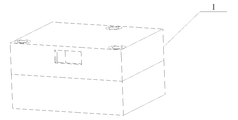
- FIG. 1 is an overall view of a dust sensor provided in accordance with an embodiment of the present invention.
- FIG. 2 is a top plan view of a main cavity of a dust sensor according to an embodiment of the present invention
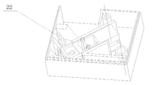
- FIG. 3 is a diagram of a venting hole on a duct of a dust sensor according to an embodiment of the present invention.
- FIG. 4 is a schematic structural view of a dust sensor according to an embodiment of the present invention.
- FIG. 5 is an assembly diagram of a laser emitting assembly and a circuit board according to an embodiment of the present invention.
- FIG. 6 is a schematic view showing the flow of air through a photosensitive element according to an embodiment of the present invention.
- FIG. 7 is a diagram of a main cavity upper cover provided in accordance with an embodiment of the present invention.
- FIG. 8 is a schematic view of a metal casing of a dust sensor according to an embodiment of the present invention.
- 9a to 9c are structural views of a laser emitting assembly according to an embodiment of the present invention.
- FIG. 10 is a schematic diagram of a laser emitting assembly including a lens in a lens assembly according to an embodiment of the present invention
- FIG. 11 is a cross-sectional view of a lens assembly including a lens emitting assembly in accordance with an embodiment of the present invention.
- FIG. 12 is a schematic diagram of a laser emitting assembly including a lens assembly of a lens assembly according to an embodiment of the present invention
- FIG. 13 is a cross-sectional view of a firing assembly of a lens assembly including two lenses, in accordance with an embodiment of the present invention.
- the present invention provides a dust sensor 1 which may include: a duct 10 through which air flow of a dust content to be measured flows; and a light emitting assembly (laser emitting unit 35 as shown) a light emitting tube (such as the laser emitting tube 30 as shown) for emitting light to illuminate a flow of air circulating in the air duct 10, and a lens assembly located on the optical path of the light for Converging light emitted by the light emitting tube; photosensitive element 11 located in the air duct 10, for receiving scattered light generated after the light is irradiated with dust; and processing means for determining a dust content based on the scattered light, wherein the photosensitive element 11 and a lens of the lens assembly that converge the light
- the detection distance is such that the resolution of the dust sensor 1 is the highest.
- the light emitting tube may be, for example, but not limited to, a laser emitting tube and an infrared emitting tube.
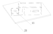
- the processing element can be designed in the form of a circuit board 21 as shown in FIG. 3.
- the laser emitting component 35 and the photosensitive element 11 are connected to the circuit board 21.
- FIG. 5 shows an assembly diagram of the laser emitting component and the circuit board in one embodiment. Show.
- the dust sensor 1 may further include: a main cavity 2, the air channel 10, the light emitting component 35, the photosensitive element 11, and the processing component (as shown in FIG.
- the display circuit board 21) is located in the main cavity 2, wherein the front wall 13 of the main cavity 2 is provided with an air inlet port 15, and the rear wall 5 of the main cavity body 2 is provided with an air outlet.
- the air flow in the environment to be tested enters the air duct 10 through the air inlet 15 and then flows out from the air outlet to achieve dust detection.
- the air duct 10 is connected between the air inlet 15 and the air outlet.
- a light trap 12 may be disposed in the main cavity 2 for absorbing light emitted by the light emitting tube, the lens assembly being located between the light trap 12 and the light emitting tube.
- the photosensitive member 11 is placed in the air duct 10, and the laser light emitted from the laser emitting unit 35 can be parallel to the photosensitive member 11.
- the emitted laser light may pass directly above the photosensitive element 11 and be incident into the optical trap 12 in the main cavity 2, and the optical trap 12 absorbs the incident laser light to reduce the noise of the reflected light.
- the light trap 12 can be made of a light absorbing material or matt treated with a non-light absorbing material.
- the dust sensor may further include a thermistor 16 for detecting the temperature of the environment in which the dust to be tested is located, since the temperature may affect the detected result.
- the thermistor can be mounted under the circuit board 21, located in the air passage of the main cavity 2, for outputting the dust sensor according to the ambient temperature. Corrected.
- the dust sensor may further comprise: an air suction device located at the air outlet for introducing the air flow from the air inlet and flowing out of the air outlet through the air passage.
- the air suction device may be a fan 3.
- the fan 3 is mounted on the rear wall 5 of the main chamber 2 through a fan mounting groove 4, wherein the position of the fan 3 may be an air outlet position.
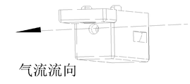
- the fan 3 can form a negative pressure by means of suctioning so that the air flow is introduced from the air inlet 15 and flows out of the air outlet through the air duct 10. As shown in FIG. 2, the air flow flows according to the air flow indicated by the arrow. flow. Wherein the photosensitive element 11 is passed through, and the laser emitting unit 35 is mounted in the main cavity 2 through the laser emitting unit mounting groove 6 so that the laser light emitted from the laser emitting tube 30 can be concentrated above the photosensitive element 11 so that the photosensitive element 11 receives the Scattered light scattered by dust.
- the air passage 10 may be L-shaped, and the intermediate angle of the L-shaped air passage 10 may be an obtuse angle, so that light is not irradiated from the fan 3 onto the photosensitive member 11, affecting the detection accuracy.
- the tail of the air duct 10 opens the vent hole 27 to make the air The flow flows out of the vent hole 27, and the vent hole 27 can be as shown in FIG.
- the main cavity 2 may include an upper cover 18 and a main body 25, wherein the air inlet 15 may be located on the upper cover 18 or on the main body 25.
- the air flow enters the main cavity 2 from the air inlet hole 15, and then passes through the air intake hole 17 on the circuit board 21 and the air passage 10, and Fig. 6 shows the flow of the air flow through the photosensitive member 11.
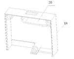
- the upper cover 18 may include a baffle 20 through which the air flow is blocked by the baffle 20 and enters the main cavity 2 through the air intake hole 17 in the circuit board 21.
- the baffle 20 blocks large particles of dust and debris and avoids detection of specific particles (e.g., PM2.5) in the air stream.
- the main cavity 2 can be wrapped by the metal casing 26, and the metal casing 26 is connected to the GND of the circuit board 21 through the connection groove 8 with a conductive material to shield the interference and improve the stability of the sensor.
- the connecting material may be a metal spring, and the connecting groove 8 is provided with a metal spring, one end of the spring is connected to the circuit board 21, and the other end is connected to the metal casing 20.
- the laser emitting assembly 35 is described below with reference to FIGS. 9a through 9c.
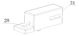
- the laser emitting tube 30 is mounted on the laser emitting tube mounting groove 31; the laser emitting unit 35 has a heat dissipating hole near the wall of the laser emitting tube 30 to prevent the temperature from affecting the power of the laser emitting tube 30.
- the laser emitting unit 35 is provided with a detecting hole 28, and the photosensitive element 11 can be mounted corresponding to the detecting hole 28 and located on the circuit board 21.
- the lens assembly may comprise a lens or two lenses, in the case of comprising two lenses, a first lens for concentrating light emitted by the light-emitting tube; and a second lens at the light emission Between the tube and the first lens, the light emitted by the light emitting tube is parallel to the optical axis of the first lens.
- the light emitting assembly 35 may further include a front aperture 27 and a rear aperture 29 to prevent light reflection.
- the rear aperture 29 is located downstream of the first lens of the lens assembly 35, and the front aperture is located at the front aperture and Downstream of the lens that converges the light in the lens assembly.
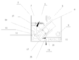
- the detection point 40 in the figure is the point at which the laser light converges after passing through the lens 36.
- the photosensitive element 11 is located below the detection point 40, the detection distance L of the photosensitive element 11 and the lens 36, and the distance from the detection point 40 to the lens 36.
- the detection point 40 at which the lens 36 converges light will also change.
- the front aperture 27 and the rear aperture 29 are located downstream of the lens 36 along the path of the laser.
- the inventors have found that in the case of one lens, the detection point 40 is different, and the resolution of the dust sensor 1 is also different. Therefore, it is obtained by the following experiment: in the case where the power of the light-emitting tube is in the range of 2.2 mW to 2.8 mW and the diameter of the lens is 6 mm, the dust sensor has the highest resolution when the detection distance L is 12 mm; And the power in the light emitting tube is in the range of 3.2 mw to 3.8 mw and the diameter of the lens is In the case of 6 mm, the dust sensor has the highest resolution when the detection distance L is 15 mm.
- those skilled in the art can determine the appropriate detection distance L according to the power of different light-emitting tubes and the diameter of the lens.
- the detection distance L is changed by changing the distance between the laser emitting tube 30 and the lens 36, and the detection result of the dust sensor under different detection distances is recorded, and the detection result is compared with the detection value of the standard instrument to obtain an error value, and then the detection distance L is different.
- the error values are compared, and the detection distance L corresponding to the minimum error value is the value that causes the dust sensor 1 to reach the highest resolution.
- Tables 1 to 4 show the errors of the dust sensor at different detection distances L in the case where the power of the laser emission tube is in the range of 2.2 mW to 2.8 mW and the diameter of the lens is 6 mm.
- Tables 5 to 8 show the errors of the dust sensor at different detection distances L in the case where the power of the laser emission tube is in the range of 3.2 mW to 3.8 mW and the diameter of the lens is 6 mm.
- the power of the laser emission tube 30 is in the range of 3.2 mW to 3.8 mW and
- the resolution of the dust sensor is the highest when the detection distance L is 15 mm.
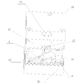
- the lens 38 collimates the light emitted by the laser emitting tube 30 parallel to the lens 37, which converges the parallel light to the detection point 40 (i.e., the focus of the lens 37), the photosensitive element 11 and The detection distance L of the lens 37 and the distance from the detection point 40 to the lens 37 (i.e., the focal length of the lens 37).
- the converging detection points 40 will also be different.
- the lens assembly includes two lenses, the lens 38, the rear aperture 29, the lens 37, and the front aperture 27 are sequentially disposed along the path direction of the laser light.
- the inventors have found that in the case of two lenses, the detection points 40 are different and the resolution of the dust sensor 1 is also different. Therefore, it is obtained by the following experiment: in the case where the power of the light-emitting tube is in the range of 2.2 mW to 2.8 mW, the dust sensor has the highest resolution when the detection distance L is 8 mm; and in the light-emitting tube In the case where the power is in the range of 3.2 mW to 3.8 mW, the dust sensor has the highest resolution when the detection distance L is 12 mm.
- those skilled in the art can determine the appropriate detection distance L according to the power of different light-emitting tubes.
- the detection distance L is changed by changing the lens 36 (ie, changing the focal length of the lens 36), and the detection result of the dust sensor under different detection distances is recorded, and the detection result is compared with the detection value of the standard instrument to obtain an error value, and then the different detection distance L is obtained.
- the error value is compared, and the detection distance L corresponding to the minimum error value is such that the dust sensor 1 reaches the highest resolution value, and the lens whose focal length is the detection distance L is such that the resolution of the dust sensor can be maximized under the power condition. Lens.
- Tables 9 to 12 show the errors of the dust sensor when the power of the laser emission tube is in the range of 2.2 mW to 2.8 mW with different detection distances L (lenses 37 having different focal lengths).
- the power of the laser emission tube 30 is in the range of 2.2 mW to 2.8 mW.
- the detection distance L is 8 mm (that is, a lens having a focal length of 8 mm is used as the lens 37)
- the resolution of the dust sensor is the highest.
- Tables 13 to 16 show the errors of the dust sensor when the power of the laser emission tube is in the range of 3.2 mW to 3.8 mW with different detection distances L (lenses 37 having different focal lengths).
- the detection distance L is 12 mm (i.e., when a lens having a focal length of 12 mm is used as the lens 37)
- the dust sensor has the highest resolution.
- the present invention is not limited to the power of the above-described laser emitting tube, and thus is not limited to the above-described detection distance L.
Landscapes
- Chemical & Material Sciences (AREA)
- Dispersion Chemistry (AREA)
- Physics & Mathematics (AREA)
- Health & Medical Sciences (AREA)
- Life Sciences & Earth Sciences (AREA)
- Analytical Chemistry (AREA)
- Biochemistry (AREA)
- General Health & Medical Sciences (AREA)
- General Physics & Mathematics (AREA)
- Immunology (AREA)
- Pathology (AREA)
- Investigating Or Analysing Materials By Optical Means (AREA)
Abstract
一种粉尘传感器(1),其包括风道(10)、光发射组件(35)、感光元件(11)以及处理元件(21)。光发射组件(35)包括光发射管(30)及透镜组件(36,37,38),光发射管(30)用于发射光以照射风道(10)中流通的空气流,透镜组件(36,37,38)位于光的光路上用于汇聚光发射管(30)发射的光。感光元件(11)位于风道(10)中,用于接收光照射粉尘后产生的散射光。处理元件(21)基于散射光确定粉尘含量,调整感光元件(11)与透镜组件(36,37,38)中汇聚光的透镜的检测距离使得粉尘传感器(1)的分辨率最高。
Description
本发明涉及粉尘检测领域,具体地,涉及一种粉尘传感器。
粉尘传感器是利用MIE散射理论对空气中悬浮颗粒进行计数或者质量浓度测量的方式。通常,粉尘传感器具有一个风道,一个光发射管、透镜及一个感光元件。空气流在风道中流动,空气流流过感光元件上方时受到激光照射产生散射光,感光元件接受到散射光,通过对散射光的分析得到空气流中粉尘的情况。
在现有技术中,粉尘传感器的感光元件位于检测点的下方,而检测点的位置通常设置于气体自由流过检测点上方,然而现有技术中,检测点的确定,即感光元件与汇聚光的透镜之间的检测距离的设定往往无法达到粉尘传感器的最高分辨率。
发明内容
本发明的目的是提供一种粉尘传感器,该粉尘传感器考虑了感光元件与汇聚光的透镜之间的检测距离对粉尘传感器的分辨率的影响,通过设置所述检测距离来提高了粉尘传感器的分辨率。
为了实现上述目的,本发明提供一种粉尘传感器,所述粉尘传感器包括:风道,待测粉尘含量的空气流在风道中流通;光发射组件,包括:光发射管,用于发射光以照射所述风道中流通的空气流,及透镜组件,位于所述光的光路上,用于汇聚所述光发射管发射的光;感光元件,位于所述风道中,用于接收所述光照射粉尘后产生的散射光;以及处理元件,基于所述散射光确定粉尘含量,其中,所述感光元件与所述透镜组件中汇聚所述光的透镜的检测距离使得所述粉尘传感器的分辨率最高。
在一些实施例中,所述透镜组件包括一个透镜。
在一些实施例中,在所述光发射管的功率位于2.2mw至2.8mw的范围内且所述透镜的直径为6mm的情况下,所述检测距离为12mm;以及在所述光发射管的功率位于3.2mw至3.8mw的范围内且所述透镜的直径为6mm的情况下,所述检测距离为15mm。
在一些实施例中,所述透镜组件包括:第一透镜,用于汇聚所述述光发射管发射的光;第二透镜,位于所述光发射管和所述第一透镜之间,用于使得所述光发射管发射的光与所述第一透镜的光轴平行。
在一些实施例中,在所述光发射管的功率位于2.2mw至2.8mw的范围内的情况下,所
述检测距离及所述第一透镜的焦距为8mm;以及在所述光发射管的功率位于3.2mw至3.8mw的范围内的情况下,所述检测距离及所述第一透镜的焦距为12mm。
在一些实施例中,所述粉尘传感器还包括:主腔体,所述风道、所述光发射组件、所述感光元件及所述处理元件位于所述主腔体中,其中所述主腔体的前壁上设置有入气口,所述主腔体的后壁上设置有出气口。
在一些实施例中,所述粉尘传感器还包括:抽气装置,位于所述出气口处,用于将所述空气流从所述入气口引入、经过所述风道从出气口流出。
在一些实施例中,所述主腔体中设置有光陷阱,用于吸收所述光发射管发射的光,所述透镜组件位于所述光陷阱和所述光发射管之间。
在一些实施例中,所述粉尘传感器还包括热敏电阻,用于检测待测粉尘所在环境的温度。
在一些实施例中,所述光发射组件还包括:前置光阑和后置光阑,沿着所述光发射管发射的光的路径方向,所述后置光阑位于所述透镜组件中第一个透镜的下游,所述前置光阑位于所述前置光阑和所述透镜组件中汇聚所述光的透镜的下游。
通过上述技术方案,设置所述感光元件与所述透镜组件中汇聚所述光的透镜的检测距离以使得所述粉尘传感器的分辨率最高。如此通过考虑感光元件与汇聚光的透镜之间的检测距离对粉尘传感器的分辨率的影响,通过设置所述检测距离来提高了粉尘传感器的分辨率。
本发明的其它特征和优点将在随后的具体实施方式部分予以详细说明。
附图是用来提供对本发明的进一步理解,并且构成说明书的一部分,与下面的具体实施方式一起用于解释本发明,但并不构成对本发明的限制。在附图中:
图1是根据本发明一种实施方式提供的粉尘传感器的整体图示;
图2是根据本发明一种实施方式提供的粉尘传感器的主腔体的俯视图;
图3是根据本发明一种实施方式提供的粉尘传感器的风道上透气孔的图示;
图4是根据本发明一种实施方式提供的粉尘传感器的结构示意图;
图5是根据本发明一种实施方式提供的激光发射组件与电路板的装配图示;
图6是根据本发明一种实施方式提供的经过感光元件的气流流向的示意图;
图7是根据本发明一种实施方式提供的主腔体上盖的图示;
图8是根据本发明一种实施方式提供的粉尘传感器的金属外壳的示意图;
图9a至9c是根据本发明一种实施方式提供的激光发射组件的结构视图;
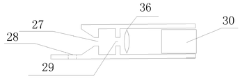
图10是根据本发明一种实施方式提供的透镜组件包括一个透镜的激光发射组件的原理图;
图11是根据本发明一种实施方式提供的透镜组件包括一个透镜的发射组件的剖面视图;
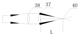
图12是是根据本发明一种实施方式提供的透镜组件包括两个透镜的激光发射组件的原理图;以及
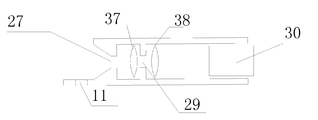
图13是根据本发明一种实施方式提供的透镜组件包括两个透镜的发射组件的剖面视图。
附图标记说明
1 粉尘传感器 2 主腔体
3 风扇 4 风扇安装位置
5 后壁 6 激光发射组件安装槽
8 连接槽 10 风道
11 感光元件 12 光陷阱
13 前壁 15 入气口
16 热敏电阻 17 进气孔
18 上盖 20 挡板
21 电路板 22 透气孔
26 金属外壳 27 前置光阑
28 检测孔 29 后置光阑
30 激光发射管 31 激光发射管安装槽
35 激光发射组件 36,37,38 透镜
40 检测点
以下结合附图对本发明的具体实施方式进行详细说明。应当理解的是,此处所描述的具体实施方式仅用于说明和解释本发明,并不用于限制本发明。
参考图1至图5,本发明提供一种的粉尘传感器1可以包括:风道10,待测粉尘含量的空气流在风道10中流通;光发射组件(如图所示的激光发射组件35),包括:光发射管(如图所示的激光发射管30),用于发射光以照射所述风道10中流通的空气流,及透镜组件,位于所述光的光路上,用于汇聚所述光发射管发射的光;感光元件11,位于所述风道
10中,用于接收所述光照射粉尘后产生的散射光;以及处理元件,基于所述散射光确定粉尘含量,其中,所述感光元件11与所述透镜组件中汇聚所述光的透镜的检测距离使得所述粉尘传感器1的分辨率最高。如此通过考虑感光元件与汇聚光的透镜之间的检测距离对粉尘传感器的分辨率的影响,通过设置所述检测距离来提高了粉尘传感器的分辨率。
其中,光发射管例如可以为但不限于激光发射管、红外发射管,下文中将以激光发射管30为例来描述本发明。处理元件可以设计为如图3所示的电路板21的形式,激光发射组件35、感光元件11与电路板21连接,图5给出了一种实施方式中激光发射组件与电路板的装配图示。
如图2至图4所示,所述粉尘传感器1还可以包括:主腔体2,所述风道10、所述光发射组件35、所述感光元件11及所述处理元件(如图所示电路板21)位于所述主腔体2中,其中所述主腔体2的前壁13上设置有入气口15,所述主腔体2的后壁5上设置有出气口。以便待测环境的空气流通过入气口15进入风道10然后从出气口流出,以实现对粉尘检测。其中风道10连接在入气口15和出气口之间。
如图所示,所述主腔体2中可以设置有光陷阱12,用于吸收所述光发射管发射的光,所述透镜组件位于所述光陷阱12和所述光发射管之间。感光元件11置于风道10中,激光发射组件35发出的激光可以与感光元件11平行。所发射的激光可以经过感光元件11的正上方,照射入主腔体2中的光陷阱12中,光陷阱12吸收射入的激光,以减少反射光的噪声。所述光陷阱12可以使用吸光材料制作,或对非吸光材料进行亚光处理。
由于温度会影响所检测的结果,因而为了提高粉尘传感器的准确性,所述粉尘传感器还可以包括热敏电阻16,用于检测待测粉尘所在环境的温度。为了热敏电阻所检测的温度更加准确地反映环境温度,所述热敏电阻可以安装于电路板21下面,位于主腔体2的风道之中,用于根据环境温度对粉尘传感器输出结果进行修正。
为了引导空气流的流通,所述粉尘传感器还可以包括:抽气装置,位于所述出气口处,用于将所述空气流从所述入气口引入、经过所述风道从出气口流出。如图2所示,所述抽气装置可以为风扇3。风扇3通过风扇安装槽4安装在主腔体2的后壁5上,其中风扇3的位置可以为出气口位置。
风扇3可以利用抽气的方式形成负压使得空气流从所述入气口15引入、经过所述风道10从出气口流出,如图2所示,所述空气流按照箭头所示的气流流向流动。其中流经感光元件11,激光发射组件35通过激光发射组件安装槽6安装在主腔体2中,以使得激光发射管30发射的激光能够汇聚在感光元件11的上方,以便感光元件11接受经粉尘散射的散射光。风道10可以为L形,所述用L形风道10的中间夹角可以为钝角,如此光线不会从风扇3照射到感光元件11上,影响检测精度。所述风道10的尾部开透气孔27,以使空气
流从透气孔27流出,透气孔27可以如图3所示。
如图4所示,主腔体2可以包括上盖18和主体25,其中入气口15可以位于上盖18上或主体25上。空气流从入气孔15进入主腔体2,然后可以通过电路板21上的进气孔17进而风道10,图6示出了通过感光元件11的空气流的气流流向。
如图7所示,上盖18可以包括挡板20,空气流被挡板20阻挡后,通过电路板21上的进气孔17进入主腔体2中。挡板20可以对大颗粒粉尘和杂物进行阻挡,避免对空气流中特定颗粒(例如PM2.5)的检测。
另外,如图8所示,主腔体2可以被金属外壳26包裹,金属外壳26通过连接槽8使用导电材料与电路板21的GND相连,以便屏蔽干扰,提高传感器的稳定性。在一种实施方式中,连接材料可以为金属弹簧,连接槽8中装配金属弹簧,弹簧一端连接电路板21,另一端连接金属外壳20。
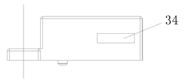
以下参考图9a至图9c来描述激光发射组件35。如图所示激光发射管30安装在激光发射管安装槽31上;激光发射组件35靠近激光发射管30的壁上具有散热孔,以避免温度对激光发射管30功率产生影响。激光发射组件35上设置有检测孔28,感光元件11可以安装对应在检测孔28的下方,位于电路板21上。
其中,所述透镜组件可以包括一个透镜或两个透镜,在包括两个透镜的情况下,第一透镜,用于汇聚所述述光发射管发射的光;第二透镜,位于所述光发射管和所述第一透镜之间,用于使得所述光发射管发射的光与所述第一透镜的光轴平行。
所述光发射组件35还可以包括:前置光阑27和后置光阑29,以防止光反射。沿着所述光发射管发射的光的路径方向,所述后置光阑29位于所述透镜组件35中第一个透镜的下游,所述前置光阑位于所述前置光阑和所述透镜组件中汇聚所述光的透镜的下游。
以下将参考图10和图11通过具体实施方式介绍透镜组件包括一个透镜的情况下检测距离的确定。
图中检测点40为激光通过透镜36后汇聚的点,感光元件11位于检测点40下方,感光元件11与透镜36的检测距离L及检测点40至透镜36的距离。对于以特定功率的激光发射管30,针对同一透镜,如果激光发射管30处于不同位置,透镜36汇聚光的检测点40也会改变。在透镜组件包括一个透镜的情况下,沿着激光的路径方向,前置光阑27和后置光阑29位于透镜36的下游。
在实践过程中,发明人发现,在一个透镜的情况下,检测点40不同,粉尘传感器1的分辨率也不同。因此,通过以下实验获得:在所述光发射管的功率位于2.2mw至2.8mw的范围内且所述透镜的直径为6mm的情况下,所述检测距离L为12mm时粉尘传感器分辨率最高;以及在所述光发射管的功率位于3.2mw至3.8mw的范围内且所述透镜的直径为
6mm的情况下,所述检测距离L为15mm时粉尘传感器分辨率最高。当然,本领域技术人员可以根据不同的光发射管的功率及透镜的直径来确定合适的检测距离L。
通过改变激光发射管30与透镜36的距离来改变检测距离L,记录不同检测距离下粉尘传感器的检测结果,将检测结果与标准仪器的检测值相比较获得误差值,然后将不同检测距离L的误差值进行比较,误差值最小对应的检测距离L即为使得粉尘传感器1达到最高分辨率的值。
表1至表4给出了激光发射管的功率位于2.2mw至2.8mw的范围内且所述透镜的直径为6mm的情况下不同检测距离L时粉尘传感器的误差。
表1

表2

表3


表4

通过表1至表4可以得出,在激光发射管30的功率位于2.2mw至2.8mw的范围内且透镜36的直径为6mm的情况下,所述检测距离L为12mm时,粉尘传感器的分辨率最高。在上述实验中可以采用650波段激光发射管,当然并不限于该波段。
表5至表8给出了激光发射管的功率位于3.2mw至3.8mw的范围内且所述透镜的直径为6mm的情况下不同检测距离L时粉尘传感器的误差。
表5

表6

表7

表8

通过表1至表4可以得出,在激光发射管30的功率位于3.2mw至3.8mw的范围内且
透镜36的直径为6mm的情况下,所述检测距离L为15mm时,粉尘传感器的分辨率最高。
以下将参考图12和图13通过具体实施方式介绍透镜组件包括两个透镜的情况下检测距离的确定。
如图12和图13所示,透镜38准直激光发射管30发射的光,使其平行于透镜37,透镜37将平行光汇聚至检测点40(即透镜37的焦点),感光元件11与透镜37的检测距离L及检测点40至透镜37的距离(即透镜37的焦距)。对于以特定功率的激光发射管30,不同的汇聚透镜(具有不同焦距),汇聚的检测点40也会不同。在透镜组件包括两个透镜的情况下,沿着激光的路径方向,依次是透镜38、后置光阑29、透镜37、前置光阑27。
在实践过程中,发明人发现,在两个透镜的情况下,检测点40不同,粉尘传感器1的分辨率也不同。因此,通过以下实验获得:在所述光发射管的功率位于2.2mw至2.8mw的范围内的情况下,所述检测距离L为8mm时粉尘传感器分辨率最高;以及在所述光发射管的功率位于3.2mw至3.8mw的范围内的情况下,所述检测距离L为12mm时粉尘传感器分辨率最高。当然,本领域技术人员可以根据不同的光发射管的功率来确定合适的检测距离L。
通过改变透镜36(即改变透镜36的焦距)来改变检测距离L,记录不同检测距离下粉尘传感器的检测结果,将检测结果与标准仪器的检测值相比较获得误差值,然后将不同检测距离L的误差值进行比较,误差值最小对应的检测距离L即为使得粉尘传感器1达到最高分辨率的值,而焦距为该检测距离L的透镜则为该功率条件下能够使得粉尘传感器分辨率达到最高的透镜。
表9至表12给出了激光发射管的功率位于2.2mw至2.8mw的范围内的情况下不同检测距离L(具有不同焦距的透镜37)时粉尘传感器的误差。
表9

表10

表11

表12

通过表9至表12可以得出,在激光发射管30的功率位于2.2mw至2.8mw的范围内的
情况下,所述检测距离L为8mm(即采用焦距为8mm的透镜作为透镜37)时,粉尘传感器的分辨率最高。
表13至表16给出了激光发射管的功率位于3.2mw至3.8mw的范围内的情况下不同检测距离L(具有不同焦距的透镜37)时粉尘传感器的误差。
表13

表14

表15


表16

通过表13至表16可以得出,在激光发射管30的功率位于3.2mw至3.8mw的范围内的情况下,所述检测距离L为12mm(即采用焦距为12mm的透镜作为透镜37)时,粉尘传感器的分辨率最高。
应该注意的是本发明并不限于上述激光发射管的功率,因而也不限于上述检测距离L。
以上结合附图详细描述了本发明的优选实施方式,但是,本发明并不限于上述实施方式中的具体细节,在本发明的技术构思范围内,可以对本发明的技术方案进行多种简单变型,这些简单变型均属于本发明的保护范围。
另外需要说明的是,在上述具体实施方式中所描述的各个具体技术特征,在不矛盾的情况下,可以通过任何合适的方式进行组合,为了避免不必要的重复,本发明对各种可能的组合方式不再另行说明。
此外,本发明的各种不同的实施方式之间也可以进行任意组合,只要其不违背本发明的思想,其同样应当视为本发明所公开的内容。
Claims (10)
- 一种粉尘传感器,其特征在于,所述粉尘传感器包括:风道,待测粉尘含量的空气流在风道中流通;光发射组件,包括:光发射管,用于发射光以照射所述风道中流通的空气流,及透镜组件,位于所述光的光路上,用于汇聚所述光发射管发射的光;感光元件,位于所述风道中,用于接收所述光照射粉尘后产生的散射光;以及处理元件,基于所述散射光确定粉尘含量,其中,所述感光元件与所述透镜组件中汇聚所述光的透镜的检测距离使得所述粉尘传感器的分辨率最高。
- 根据权利要求1所述的粉尘传感器,其特征在于,所述透镜组件包括一个透镜。
- 根据权利要求2所述的粉尘传感器,其特征在于,在所述光发射管的功率位于2.2mw至2.8mw的范围内且所述透镜的直径为6mm的情况下,所述检测距离为12mm;以及在所述光发射管的功率位于3.2mw至3.8mw的范围内且所述透镜的直径为6mm的情况下,所述检测距离为15mm。
- 根据权利要求1所述的粉尘传感器,其特征在于,所述透镜组件包括:第一透镜,用于汇聚所述述光发射管发射的光;第二透镜,位于所述光发射管和所述第一透镜之间,用于使得所述光发射管发射的光与所述第一透镜的光轴平行。
- 根据权利要求4所述的粉尘传感器,其特征在于,在所述光发射管的功率位于2.2mw至2.8mw的范围内的情况下,所述检测距离及所述第一透镜的焦距为8mm;以及在所述光发射管的功率位于3.2mw至3.8mw的范围内的情况下,所述检测距离及所述第一透镜的焦距为12mm。
- 根据权利要求1所述的粉尘传感器,其特征在于,所述粉尘传感器还包括:主腔体,所述风道、所述光发射组件、所述感光元件及所述处理元件位于所述主腔体中,其中所述主腔体的前壁上设置有入气口,所述主腔体的后壁上设置有出气口。
- 根据权利要求6所述的粉尘传感器,其特征在于,所述粉尘传感器还包括:抽气装置,位于所述出气口处,用于将所述空气流从所述入气口引入、经过所述风道从出气口流出。
- 根据权利要求1所述的粉尘传感器,其特征在于,所述主腔体中设置有光陷阱,用 于吸收所述光发射管发射的光,所述透镜组件位于所述光陷阱和所述光发射管之间。
- 根据权利要求1所述的粉尘传感器,其特征在于,所述粉尘传感器还包括热敏电阻,用于检测待测粉尘所在环境的温度。
- 根据权利要求1-9中任一项所述的粉尘传感器,其特征在于,所述光发射组件还包括:前置光阑和后置光阑,沿着所述光发射管发射的光的路径方向,所述后置光阑位于所述透镜组件中第一个透镜的下游,所述前置光阑位于所述前置光阑和所述透镜组件中汇聚所述光的透镜的下游。
Applications Claiming Priority (4)
| Application Number | Priority Date | Filing Date | Title |
|---|---|---|---|
| CN201620888257.XU CN205982006U (zh) | 2016-08-16 | 2016-08-16 | 一种粉尘传感器 |
| CN201620888257.X | 2016-08-16 | ||
| CN201610674439.1A CN106053311B (zh) | 2016-08-16 | 2016-08-16 | 一种粉尘传感器 |
| CN201610674439.1 | 2016-08-16 |
Publications (1)
| Publication Number | Publication Date |
|---|---|
| WO2018032802A1 true WO2018032802A1 (zh) | 2018-02-22 |
Family
ID=61196263
Family Applications (1)
| Application Number | Title | Priority Date | Filing Date |
|---|---|---|---|
| PCT/CN2017/082953 Ceased WO2018032802A1 (zh) | 2016-08-16 | 2017-05-03 | 一种粉尘传感器 |
Country Status (1)
| Country | Link |
|---|---|
| WO (1) | WO2018032802A1 (zh) |
Cited By (5)
| Publication number | Priority date | Publication date | Assignee | Title |
|---|---|---|---|---|
| CN108318081A (zh) * | 2018-03-30 | 2018-07-24 | 惠州华阳通用电子有限公司 | 一种检测汽车内外空气质量的装置 |
| CN110715883A (zh) * | 2018-07-12 | 2020-01-21 | 常州承信投资合伙企业(有限合伙) | 空气质量检测装置及其应用 |
| CN111307680A (zh) * | 2020-03-10 | 2020-06-19 | 深圳市宇驰环境技术有限公司 | 穿戴设备 |
| CN112903551A (zh) * | 2021-02-05 | 2021-06-04 | 顺德职业技术学院 | 一种激光粉尘传感器及其自动补偿方法 |
| US12313518B2 (en) | 2019-09-06 | 2025-05-27 | Safera Oy | Device for measuring the quality of air |
Citations (7)
| Publication number | Priority date | Publication date | Assignee | Title |
|---|---|---|---|---|
| JP2010281660A (ja) * | 2009-06-04 | 2010-12-16 | Nitta Ind Corp | 微粒子計測装置、および微粒子モニタリング装置 |
| CN103822858A (zh) * | 2014-02-28 | 2014-05-28 | 苏州亿利安机电科技有限公司 | 一种具有粉尘传感器的粉尘浓度在线监测装置 |
| CN103837451A (zh) * | 2014-02-28 | 2014-06-04 | 苏州亿利安机电科技有限公司 | 一种用于在线监测粉尘浓度的粉尘传感器 |
| CN204142613U (zh) * | 2014-10-15 | 2015-02-04 | 深圳市信诚佳业电子有限公司 | 一种高精度小型化粉尘传感器 |
| WO2015151502A1 (ja) * | 2014-04-03 | 2015-10-08 | パナソニックIpマネジメント株式会社 | 粒子検出センサ、ダストセンサ、煙感知器、空気清浄機、換気扇及びエアコン |
| CN106053311A (zh) * | 2016-08-16 | 2016-10-26 | 广东美的制冷设备有限公司 | 一种粉尘传感器 |
| CN205982006U (zh) * | 2016-08-16 | 2017-02-22 | 广东美的制冷设备有限公司 | 一种粉尘传感器 |
-
2017
- 2017-05-03 WO PCT/CN2017/082953 patent/WO2018032802A1/zh not_active Ceased
Patent Citations (7)
| Publication number | Priority date | Publication date | Assignee | Title |
|---|---|---|---|---|
| JP2010281660A (ja) * | 2009-06-04 | 2010-12-16 | Nitta Ind Corp | 微粒子計測装置、および微粒子モニタリング装置 |
| CN103822858A (zh) * | 2014-02-28 | 2014-05-28 | 苏州亿利安机电科技有限公司 | 一种具有粉尘传感器的粉尘浓度在线监测装置 |
| CN103837451A (zh) * | 2014-02-28 | 2014-06-04 | 苏州亿利安机电科技有限公司 | 一种用于在线监测粉尘浓度的粉尘传感器 |
| WO2015151502A1 (ja) * | 2014-04-03 | 2015-10-08 | パナソニックIpマネジメント株式会社 | 粒子検出センサ、ダストセンサ、煙感知器、空気清浄機、換気扇及びエアコン |
| CN204142613U (zh) * | 2014-10-15 | 2015-02-04 | 深圳市信诚佳业电子有限公司 | 一种高精度小型化粉尘传感器 |
| CN106053311A (zh) * | 2016-08-16 | 2016-10-26 | 广东美的制冷设备有限公司 | 一种粉尘传感器 |
| CN205982006U (zh) * | 2016-08-16 | 2017-02-22 | 广东美的制冷设备有限公司 | 一种粉尘传感器 |
Cited By (7)
| Publication number | Priority date | Publication date | Assignee | Title |
|---|---|---|---|---|
| CN108318081A (zh) * | 2018-03-30 | 2018-07-24 | 惠州华阳通用电子有限公司 | 一种检测汽车内外空气质量的装置 |
| CN108318081B (zh) * | 2018-03-30 | 2024-04-09 | 惠州华阳通用电子有限公司 | 一种检测汽车内外空气质量的装置 |
| CN110715883A (zh) * | 2018-07-12 | 2020-01-21 | 常州承信投资合伙企业(有限合伙) | 空气质量检测装置及其应用 |
| US12313518B2 (en) | 2019-09-06 | 2025-05-27 | Safera Oy | Device for measuring the quality of air |
| CN111307680A (zh) * | 2020-03-10 | 2020-06-19 | 深圳市宇驰环境技术有限公司 | 穿戴设备 |
| CN111307680B (zh) * | 2020-03-10 | 2022-10-21 | 深圳市宇驰环境技术有限公司 | 穿戴设备 |
| CN112903551A (zh) * | 2021-02-05 | 2021-06-04 | 顺德职业技术学院 | 一种激光粉尘传感器及其自动补偿方法 |
Similar Documents
| Publication | Publication Date | Title |
|---|---|---|
| CN205374238U (zh) | 粉尘浓度传感器及具有该粉尘浓度传感器的空气净化器 | |
| WO2018032802A1 (zh) | 一种粉尘传感器 | |
| CN109791104B (zh) | 颗粒物传感器装置 | |
| TWI437513B (zh) | 煙偵測器及其採樣空氣供應方法 | |
| WO2018045768A1 (zh) | 家用电器、粉尘传感器及其标定方法、标定装置 | |
| CN110987745A (zh) | 颗粒物检测装置及检测方法 | |
| EP3220124B1 (en) | Particle sensor, and electronic device provided with same | |
| CN106053311A (zh) | 一种粉尘传感器 | |
| WO2017090134A1 (ja) | 粒子センサ | |
| CN101162194A (zh) | 测量尘埃粒子的光学传感器 | |
| KR20200009707A (ko) | 미세먼지 측정 장치 및 방법 | |
| CN205982006U (zh) | 一种粉尘传感器 | |
| CN106066296A (zh) | 一种pm2.5检测装置 | |
| CN110780035A (zh) | 具有校准功能的车用空气质量检测装置及车辆 | |
| CN106483052A (zh) | 一种基于光散射法的pm2.5检测仪 | |
| JPWO2019167485A1 (ja) | 粒子検出センサ | |
| CN112730180A (zh) | 一种具有双探测器的高灵敏度尘埃粒子计数传感器 | |
| CN205449752U (zh) | 灰尘浓度传感器 | |
| US9921144B2 (en) | Particulate matter detector | |
| CN201130141Y (zh) | 尘埃粒子计数器光学传感器 | |
| CN108680476A (zh) | 一种颗粒物浓度检测装置 | |
| CN111141646A (zh) | 一种基于β射线法和光散射原理的颗粒物实时测量装置 | |
| CN208383653U (zh) | 室外风扇式激光粉尘检测结构 | |
| CN200941092Y (zh) | 空气悬浮颗粒物颗粒数及质量浓度检测仪 | |
| CN110220828A (zh) | 一种颗粒物监测仪 |
Legal Events
| Date | Code | Title | Description |
|---|---|---|---|
| 121 | Ep: the epo has been informed by wipo that ep was designated in this application |
Ref document number: 17840778 Country of ref document: EP Kind code of ref document: A1 |
|
| NENP | Non-entry into the national phase |
Ref country code: DE |
|
| 122 | Ep: pct application non-entry in european phase |
Ref document number: 17840778 Country of ref document: EP Kind code of ref document: A1 |