WO2018025359A1 - タッチ入力装置 - Google Patents
タッチ入力装置 Download PDFInfo
- Publication number
- WO2018025359A1 WO2018025359A1 PCT/JP2016/072868 JP2016072868W WO2018025359A1 WO 2018025359 A1 WO2018025359 A1 WO 2018025359A1 JP 2016072868 W JP2016072868 W JP 2016072868W WO 2018025359 A1 WO2018025359 A1 WO 2018025359A1
- Authority
- WO
- WIPO (PCT)
- Prior art keywords
- touch input
- touch
- unit
- dimensional
- input device
- Prior art date
- Legal status (The legal status is an assumption and is not a legal conclusion. Google has not performed a legal analysis and makes no representation as to the accuracy of the status listed.)
- Ceased
Links
Images



Classifications
-
- G—PHYSICS
- G06—COMPUTING OR CALCULATING; COUNTING
- G06F—ELECTRIC DIGITAL DATA PROCESSING
- G06F3/00—Input arrangements for transferring data to be processed into a form capable of being handled by the computer; Output arrangements for transferring data from processing unit to output unit, e.g. interface arrangements
- G06F3/01—Input arrangements or combined input and output arrangements for interaction between user and computer
- G06F3/02—Input arrangements using manually operated switches, e.g. using keyboards or dials
Definitions
- the present invention relates to a touch input device, and particularly to a touch input device having a three-dimensional touch surface.
- a touch input unit for detecting an input position is attached to the display surface of a display device in a personal computer, a portable terminal, an electronic notebook, an OA device, a game machine, a PDA, a bank terminal (cash dispenser), a ticket machine, and the like.
- Touch input devices are known.
- the touch input unit included in such a touch input device includes a touch electrode unit for detecting a touch position formed on one surface of a planar substrate made of glass or the like. Has been configured.
- the conventional touch input device is operated by the user by touching a predetermined area corresponding to the button partial image in the video that the display device transmits to the touch input unit. It is necessary to visually confirm a button partial image to be touched and to perform a touch operation while viewing the displayed button partial image. In other words, when operating the touch input device, the user must always visually check the video displayed on the display device, and can perform a touch operation with the eyes away from the displayed video. There was a problem that it was difficult.
- the present invention has been made to solve such a problem, and it is not necessary for the user to continue to visually observe the place where the touch input is to be made on the touch surface, and an intuitive touch operation can be performed.
- An object is to provide an input device.
- the above object of the present invention is a touch input device capable of detecting a touch input signal, comprising a touch input unit and display means for projecting or transmitting an image on the touch input unit, wherein the touch input unit includes: A three-dimensional substrate having a main surface portion on which an image displayed by the display means is projected or transmitted, and a three-dimensional portion formed as at least one of a convex shape and a concave shape with respect to the surface of the main surface portion; It is achieved by a touch input device comprising a touch electrode portion formed in a region corresponding to a three-dimensional portion.
- the display unit projects or transmits an information image indicating a touch input position with respect to the touch input unit to a user in an area corresponding to the three-dimensional unit.
- the contour shape of the three-dimensional portion in plan view matches the contour shape of the information image projected or transmitted by the display means on the region corresponding to the three-dimensional portion.
- the main surface portion of the three-dimensional substrate is formed in a planar shape or a curved surface shape.
- a detection unit that detects a touch input signal from an electrical change of the touch input unit; and a control unit that changes an image projected or transmitted to the touch input unit based on the touch input signal detected by the detection unit. It is preferable to further provide.
- the three-dimensional substrate is provided with a light diffusion layer
- the display means is a projection display device that projects an image on the touch input unit.
- a touch input device that can perform an intuitive touch operation without requiring the user to continue to visually observe a place on the touch surface where touch input is to be performed.
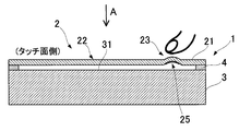
- FIG. 10 is a schematic cross-sectional view illustrating a modification of the touch input device illustrated in FIG. 1.
- FIG. 7 is a schematic cross-sectional view illustrating another modification of the touch input device illustrated in FIG. 1.
- FIG. 7 is a schematic cross-sectional view illustrating another modification of the touch input device illustrated in FIG. 1.
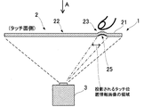
- FIG. 1 is a schematic cross-sectional view of a touch input device 1 according to the present invention
- FIG. 2 is a plan view seen from the direction of arrow A.
- a touch input device 1 according to the present invention is a touch input device 1 capable of detecting a touch input signal, and includes a capacitive touch input unit 2 and a display unit 3.
- the touch input unit 2 is a member that is disposed on the front side of the display unit 3 and that allows the user to perform a touch operation.
- the touch input unit 2 includes a three-dimensional substrate 21 and a touch electrode unit 25.
- the three-dimensional substrate 21 has a main surface portion 22 on which an image displayed by the display unit 3 is projected or transmitted, and a three-dimensional portion 23 formed as at least one of a convex shape and a concave shape with respect to the surface of the main surface portion 22.
- the front surface of the three-dimensional substrate 21 (the surface opposite to the side on which the display unit 3 is arranged) constitutes a touch surface that is touched by the user.
- the three-dimensional substrate 21 is configured by forming the dome-shaped three-dimensional portion 23 so as to be convex toward the touch surface and to have a circular outline shape in plan view.
- the three-dimensional substrate 21 may be configured by laminating a hard coat layer for preventing scratches, an antifouling coating layer, an antireflection layer, or the like on the surface of the three-dimensional substrate 21 on the touch surface side.
- the contour shape in plan view of the three-dimensional part 23 included in the three-dimensional substrate 21 is configured to be circular, but is not limited to such a form, for example, in plan view.
- the solid portion 23 may be configured in various forms such as a rectangular shape, an elliptical shape, a trapezoidal shape, and a star shape.
- the touch electrode unit 25 is provided in each of the regions corresponding to the step portions 231, and the touch input device 1 is operated by a touch operation on each step portion 231. May be configured to perform different operations (for example, an operation of displaying different images in response to a touch operation on each stepped portion 231).
- the material forming the three-dimensional substrate 21 is preferably a dielectric material and is made of a highly transparent resin material.
- a resin material such as polymethyl methacrylate (PMMA) or polycarbonate (PC) which is a thermoplastic resin can be preferably used.
- the three-dimensional substrate 21 may be formed using various resin materials capable of forming the three-dimensional portion 23, without being limited to such a resin material.
- the touch electrode portion 25 is formed on the three-dimensional substrate.
- the touch electrode unit 25 is a unit that generates a touch signal when a person touches the touch surface, and is formed on an area corresponding to the three-dimensional unit 23 on one side of the three-dimensional substrate 21. Yes.
- the touch electrode portion 25 is formed on the concave surface of the three-dimensional portion 23 on the surface side of the three-dimensional substrate 21 facing the display means 3 side.
- the touch electrode portion 25 can be formed, for example, as a mesh pattern having a certain aperture ratio (for example, 60% or more) of a fine metal wire having a line width of 1 to 50 ⁇ m.
- the touch electrode unit 25 As a material for forming the fine metal wire, for example, a metal material such as copper or nickel can be used. You may further provide a rust prevention coating layer, an adhesion layer, a blackening layer, etc. with respect to a metal fine wire.
- the specific form of the touch electrode unit 25 is not limited to the mesh shape, but touch input such as an ITO film formed by sputtering or a transparent conductive film formed by applying conductive fine particles such as carbon nanotubes. Any form that can detect a signal can be adopted.
- the touch electrode unit 25 is configured to be formed on one surface side of the three-dimensional substrate 21 (the surface side of the three-dimensional substrate 21 facing the display unit 3 side).
- the touch electrode unit 25 may be disposed on the other surface side (touch surface side) of the three-dimensional substrate 21.
- a protective sheet (protective layer) for protecting the touch electrode unit 25 is disposed on the touch electrode unit 25.
- the touch input unit 2 configured as described above can be formed by, for example, the following method. First, reducing polypyrrole fine particles and a binder are placed at a predetermined position (position where the touch electrode portion 25 is formed) on one surface of a flat substrate formed of a resin material such as polymethyl methacrylate (PMMA) or polycarbonate (PC). The coating material is applied in a form corresponding to the mesh pattern of the touch electrode portion 25 to form a coating layer. Thereafter, a predetermined position (peripheral position where the coating film layer is formed) of the flat substrate is three-dimensionally deformed by a vacuum forming technique or the like, and the three-dimensional portion 23 that is convex from one side to the other side is formed. Form.
- a predetermined position peripheral position where the coating film layer is formed
- the catalytic metal is adsorbed by ion reduction on the coating layer on the three-dimensional substrate 21 on which the three-dimensional part 23 is formed, and then a metal layer made of copper or nickel is deposited by electroless plating.
- the deposited metal layer has a mesh pattern shape, which becomes the touch electrode portion 25.
- the formation method of the touch input part 2 is not specifically limited to such a method,
- a wiring portion (not shown) that is electrically connected to the touch electrode portion 25 is formed on the surface side where the touch electrode portion 25 is formed.
- the wiring portion may be formed by the same method as the method of forming the touch electrode portion 25 by plating as described above, or after the touch electrode portion 25 is formed by plating as described above, the conductive ink is applied in a predetermined manner. You may form by apply
- a detection unit (not shown) is electrically connected to the wiring unit.
- the detection unit detects whether or not there is a touch input from an electrical change of the touch input unit 2 (touch electrode unit 25), that is, from a signal (touch input signal) related to the touch position on the three-dimensional substrate 21 detected by the touch electrode unit 25. It is a means to detect.
- the display means 3 is a device that projects or transmits an image on the touch input unit 2, and various types of display devices can be employed.
- a projection display device projector device
- the image to be displayed is projected onto the touch input unit 2 to be the main of the three-dimensional substrate 21.
- the image is projected on the surface portion 22 so that the user can visually recognize the image.
- the three-dimensional substrate 21 is preferably configured to include a light diffusion layer.
- the light diffusion layer is a layer for isotropically diffusing the image light incident from the projection display device to be emitted from the touch surface side and delivering it to the user.
- the light diffusion layer is made of a known material and a forming method. be able to.
- the light diffusing layer is composed of a base material made of a transparent resin and a diffusing component dispersed in the base material, and the refractive index difference between the base material and the diffusing component or the reflecting property of the diffusing component itself.
- the diffusing component it is preferable to use highly transparent resin beads such as acrylic beads, melamine beads, acrylic-styrene beads, polycarbonate beads, polyethylene beads, polystyrene beads, and the like.
- the display means 3 is connected to a control unit (not shown) that changes an image projected or transmitted to the touch input unit 2 based on the touch input signal detected by the detection unit.
- the control unit is shown in a region indicated by a one-dot chain line in FIG. 2 when the user repeats a touch operation on the three-dimensional unit 23 of the three-dimensional substrate 21 on which the touch electrode unit 25 is formed.
- the video content to be displayed is sequentially switched and displayed. Since the control unit only needs to be configured so that the touch input signal detected by the detection unit can be received, the detection unit and the control unit may be directly connected by wiring, or the detection unit The detection unit and the control unit may be configured to wirelessly transmit the touch input signal detected by the control unit to the control unit.
- the display unit 3 is configured to project or transmit an information image (touch position information image) indicating the touch input position with respect to the touch input unit to the user in an area corresponding to the three-dimensional unit 23.
- an information image touch position information image
- the touch position information image may be configured such that the color projected on the area corresponding to the three-dimensional unit 23 is different from the color projected on the area other than the area, or the character image or the character information image.
- the contour shape of the three-dimensional portion 23 on the three-dimensional substrate 21 in plan view matches the contour shape of the information image (touch position information image) that the display unit 3 projects onto the area corresponding to the three-dimensional portion 23. It may be configured.
- match means that the contour shape is not required to be completely matched when viewed from all angles, and the contour shape is such that the operator can sufficiently recognize the touch position (possible range). Means match.
- the display unit 3 projects the main surface portion 22 of the touch input unit 2 or the like.
- a video part (touch position information image) to be projected onto an area corresponding to the three-dimensional part 23 is configured as a symbol information image indicating that the part is touch-input, and the contour of the symbol information image is displayed.
- the shape is configured to be a circular shape that substantially matches the contour shape of the solid portion 23 in plan view.
- the detection method of the touch operation is the same as that of the conventional capacitive touch input device, and the detection method is appropriately selected depending on the purpose such as the self-capacitance detection method and the mutual capacitance detection method. it can.
- the touch electrode part 25 arranged on the three-dimensional part 23 is grounded via the capacitance of the human body at the contact position, and the current value flowing through the touch electrode part 25
- the detection unit detects the touch input signal from the change in the number, and based on the touch input signal detected by the detection unit, the control unit performs arithmetic processing to change the image projected or transmitted through the touch input unit 2.
- the display unit 3 displays different images before and after the touch operation, and provides the different images to the user via the touch input unit 2.
- the display means 3 is projected or permeate
- touch input is performed by forming a three-dimensional portion 23 formed as at least one of a convex shape and a concave shape on the surface of the main surface portion 22 on which an image displayed by the display unit 3 is projected or transmitted. Since the device 1 is configured, the user of the touch input device 1 confirms the content of the video displayed by the display unit, and grasps which location is the position where the touch input is to be performed before the touch input. Only by looking at the main surface portion 22 of the device 1, it is possible to intuitively think that the three-dimensional portion 23 is a position where touch input is to be performed.
- the user of the touch input device 1 can continuously perform the touch operation without the user continuously observing the place on the touch surface where the touch input is to be performed. More specifically, the user who operates the touch input device 1 according to the present invention determines a portion (three-dimensional portion 23) where touch input is to be performed together with an image displayed by viewing the main surface portion 22 of the touch input device 1. Although it will be recognized, at this time, the approximate position of the place (solid portion 23) to be touch-input is stored in the user. When the touch operation is actually performed, if the finger is moved to the approximate position of the stored touch input portion (three-dimensional portion 23), the finger changes the undulation of the three-dimensional portion 23 on the main surface portion 22.
- the user can recognize that the position is a place where touch input is to be performed, and a touch operation on the place can be performed.
- a touch operation on the place can be performed.
- tactile sensation can be used, there is no need to keep looking at the place where touch input is to be performed when touch input, and the user can grasp the place where touch input is to be performed intuitively and reliably. It is possible to operate the touch input device 1 while concentrating the consciousness on the video that is switched and displayed by the operation.
- the display unit 3 is configured to project or transmit an information image indicating the touch input position with respect to the touch input unit to the user in an area corresponding to the three-dimensional unit 23.
- the recognition of the information image indicating the touch input position displayed on the three-dimensional unit 23 by the display unit 3, the visual recognition of the shape of the three-dimensional unit 23, and the three-dimensional unit 23 using a finger Recognition by the tactile sense of the shape (undulations) of the user acts on the user.
- the contour shape of the three-dimensional unit 23 in plan view matches the contour shape of the information image (touch position information image) that the display unit 3 projects or transmits in the region corresponding to the three-dimensional unit 23. It is configured as follows. As described above, when the contour shape of the three-dimensional unit 23 in plan view and the contour shape of the touch position information image are configured to match, the consistency of the combination of the visual and tactile stimuli regarding the portion to be touch-inputted is described. It is possible to improve the interaction between visual and tactile sensations, and it is possible to make the user act more strongly. As a result, when performing touch input, it is possible to more effectively prevent a touch location from being mistaken or a touch operation deviating from the center position of the touch input location, which is extremely reliable. The user can perform the touch operation.
- the embodiment of the touch input device 1 according to the present invention has been described above, but the specific configuration is not limited to the above embodiment.
- a single three-dimensional portion that forms a discontinuous surface with respect to the surface of the main surface portion 22 on which the image displayed by the display means is projected or transmitted.
- the three-dimensional substrate 21 is configured so as to have 23, but is not limited to such a form.
- the three-dimensional substrate 21 is formed so as to have a plurality of three-dimensional portions 23, and one surface side of the three-dimensional substrate 21 is formed.
- the touch electrode unit 25 may be arranged in each region corresponding to each three-dimensional unit 23.
- the contour shape in plan view of the three-dimensional part 23 and the display unit 3 are projected or projected onto a region corresponding to the three-dimensional part 23.
- the outline shape of the information image to be transmitted may be configured to match each other, or the outline shape in the plan view of the three-dimensional unit 23 and the touch position information image with respect to some sets. You may comprise so that the outline shape may agree
- a touch electrode unit 25 is configured as a set of a plurality of touch electrode bodies 251, and an image corresponding to the touch position is obtained by touching the three-dimensional unit 23 on which each touch electrode body 251 is formed. You may comprise so that it may be displayed.
- Various shapes can be employed as the shape of each touch electrode body 251.
- each touch electrode body 251 is formed in a fan shape, and the plurality of fan-shaped touch electrode bodies 251 are arranged concentrically to constitute the touch electrode portion 25.
- An insulating region is formed between the touch electrode bodies 251 so that a touch input signal input to one touch electrode body 251 is not supplied to another adjacent touch electrode body 251. Yes.
- the touch electrode unit 25 is configured as a so-called slider bar type or scroll wheel type.
- the slider bar type touch electrode unit 25 is configured, for example, as shown in FIG. 5, a plurality of touch electrode bodies 251 may be arranged along one direction.
- the scroll wheel type touch electrode unit 25 is configured, the configuration of the touch electrode unit 25 shown in FIG. 4 described above can be employed.
- the detection unit is configured to recognize that a proper slide input is made when touch input signals from the touch electrode bodies 251 are sequentially input along one direction within a predetermined time. .
- the three-dimensional portion 23 of the three-dimensional substrate 21 is configured to be convex toward the touch surface side, but is not particularly limited to such a configuration.
- the three-dimensional portion 23 may be formed so as to be convex toward the display unit side and the touch surface side to be a concave portion.
- the touch electrode portion 25 is preferably formed on the surface of the three-dimensional substrate 21 facing the display unit 3 and on the convex surface protruding to the display unit 3 side.
- the three-dimensional unit is not intended to perform the touch operation. It is possible to effectively prevent the malfunction that the touch input device 1 is driven by touching the touch panel 23.
- both the three-dimensional portion 23 that is convex when viewed from the touch surface side as shown in FIG. 1 and the three-dimensional portion 23 that is concave when viewed from the touch surface side as shown in FIG. 6 are provided.
- the three-dimensional substrate 21 may be configured.
- substrate 21 has is comprised as planar as shown in FIG.
- the surface shape of the main surface portion 22 may be configured as a curved surface as shown in FIG. 7 so that the boundary portion can be grasped.
- the case where a projection display device (projector device) that projects an image on the touch input unit 2 and provides the image to the user is adopted as the display unit 3.
- various types of display devices can be employed.
- a liquid crystal display in which the touch input unit 2 is installed is adopted as the display unit 3, and the displayed video is transmitted through the touch input unit 2 so that the user can visually recognize the video. You may comprise so that it can do.
- the adhesive layer 4 is arranged in a frame shape around the display surface 31 side of the display unit 3 (liquid crystal display device), and the display unit 3 and the touch input device 1 are interposed via the adhesive layer 4. And are integrated.
- the pressure-sensitive adhesive layer 4 a general transparent adhesive or pressure-sensitive adhesive such as epoxy or acrylic can be used, and it may include a core made of a norbornene-based resin transparent film. Note that the region where the adhesive layer 4 is pasted in the touch input unit 2 is not a region through which the image displayed by the display unit 3 is transmitted, and thus does not constitute the main surface portion 22.
- a transparent photo-curing resin material may be applied to the surface of the display means 3 and the touch input unit 2 may be placed, and then the photo-curing resin material may be cured and fixed by irradiating ultraviolet rays or the like.
- an organic EL display is used as the display device 3 so that the image displayed on the organic EL display can be transmitted to the touch input unit 2 so that the user can visually recognize the image.
- the organic EL display (display device 3) is arranged along the surface of the three-dimensional part 23 included in the three-dimensional substrate 21, as shown in FIG.
- the touch input device 1 can be made more compact and design variations can be diversified.
- the touch input device 1 has a configuration in which the touch electrode unit 25 is disposed at a position corresponding to the three-dimensional unit 23 and is driven only by a touch operation on the three-dimensional unit 23.
- a matrix-shaped touch electrode portion is formed in the region indicated by the alternate long and short dash line in FIG. 2 on one surface side of the three-dimensional substrate 21, and a touch position recognition function is given to the region. It may be configured so that a part other than the three-dimensional part 23 can be touch-operated.
- the touch electrode part 23 may be formed directly on the surface of the three-dimensional board
- a resin film or a resin layer may be interposed between the surface of the three-dimensional substrate 21 and the touch electrode unit 23, and the touch electrode unit 23 may be formed on the resin film or the like.
- control content of the video display displayed by the display means 3 is not particularly limited, and various display control details can be adopted.
- the video display is turned off, and the video is displayed when the user approaches the predetermined distance.
- a landscape image, an advertisement image, or the like is displayed on the entire main surface portion 22 (including the three-dimensional portion 23) of the touch input portion.
- an information image indicating the touch input position for the touch input unit to the user is displayed on the three-dimensional unit 23 and other than the three-dimensional unit 23.
- the video display may be turned off if there is no touch input for a certain period of time, and the video may be displayed by touching the touch input unit.
- the contour shape of the touch input unit 2 in plan view is configured to be rectangular as shown in FIG. 2, but is not particularly limited to such a configuration.
- the contour shape in plan view of the touch input unit 2 is configured to be a non-rectangular shape imitating the contour shape of various products distributed in the market such as clothes such as T-shirts, and the display unit 3
- An image that matches the contour shape of the touch input unit 2 may be projected or transmitted through the touch input unit 2.
- the touch input device 1 having such a configuration is installed in a store such as a clothing such as a T-shirt, the user of the touch input device 1 can touch the touch input device 1 by touching the three-dimensional unit 23.
- the contour shape of the touch input unit 2 simulates the contour shape of clothes that are commodities, the user himself / herself through the operation of the touch input device 1 without having to pick up and confirm the actual commodities. It becomes possible to make the user himself / herself effectively sense the taste and impression of the product.
- the touch input device 1 according to the present invention can be suitably used, for example, as a console panel for operation of a car navigation system of an automobile or an audio system.
- the driver When used as a console panel, the driver can perform an intuitive operation by relying on the change in the undulation of the three-dimensional part 23 without observing the information displayed on the console panel. As a result, it becomes possible to drive a car more intensively.
- the said console panel can be formed as a form along the surface shape of the housing
Landscapes
- Engineering & Computer Science (AREA)
- General Engineering & Computer Science (AREA)
- Theoretical Computer Science (AREA)
- Human Computer Interaction (AREA)
- Physics & Mathematics (AREA)
- General Physics & Mathematics (AREA)
- Position Input By Displaying (AREA)
Abstract
タッチ面におけるタッチ入力すべき個所を使用者が目視し続ける必要が無く、直感的なタッチ操作を行うことができるタッチ入力装置を提供する。 タッチ入力信号を検出可能なタッチ入力装置であって、タッチ入力部と、前記タッチ入力部に映像を投影又は透過させる表示手段とを備えており、前記タッチ入力部は、前記表示手段が表示する映像が投影又は透過される主面部、及び、前記主面部の表面に対して凸状及び凹状の少なくともいずれか一方として形成される立体部を有する立体状基板と、前記立体部に対応する領域に形成されるタッチ電極部とを備えることを特徴とするタッチ入力装置。
Description
本発明は、タッチ入力装置に関し、特に立体形状のタッチ面を有するタッチ入力装置に関する。
従来から、パソコン、携帯端末、電子手帳、OA機器、ゲーム機、PDA、銀行端末(キャッシュディスペンサー)、券売機等における表示装置のディスプレイ表面に、入力位置を検出するためのタッチ入力部を取り付けたタッチ入力装置が知られている。このようなタッチ入力装置が有するタッチ入力部は、例えば、特許文献1に開示されているように、ガラス等により構成される平面状の基板の一方面にタッチ位置検出用のタッチ電極部が形成されて構成されている。
従来のタッチ入力装置は、表示装置がタッチ入力部に透過させる映像中のボタン部分画像に対応する所定領域をタッチすることにより、使用者が操作するものであるが、このとき、使用者は、タッチすべきボタン部分画像を目視により確認した上、更に、表示されるボタン部分画像を目視しながらタッチ操作を行う必要がある。つまり、使用者は、タッチ入力装置を操作する際、常に、表示装置により表示される映像を目視によって確認し続けなくてはならず、表示される映像から目を離したタッチ操作を行うことは困難であるという問題があった。なお、ボタン部分画像の位置を目視により確認した後、その記憶を頼りに、表示画像から目を離した状態でボタン部分画像(タッチすべき個所)のおおよその位置をタッチして、タッチ入力装置の操作を行うことは可能であるが、このような場合、誤った位置をタッチしてしまい、所望の動作とは異なる動作をタッチ入力装置に作動させてしまう可能性が極めて高く、確実なタッチ操作を行うことはできない。
本発明は、このような問題を解決するためになされたものであって、タッチ面におけるタッチ入力すべき個所を使用者が目視し続ける必要が無く、直感的なタッチ操作を行うことができるタッチ入力装置を提供することを目的とする。
本発明の上記目的は、タッチ入力信号を検出可能なタッチ入力装置であって、タッチ入力部と、前記タッチ入力部に映像を投影又は透過させる表示手段とを備えており、前記タッチ入力部は、前記表示手段が表示する映像が投影又は透過される主面部、及び、前記主面部の表面に対して凸状及び凹状の少なくともいずれか一方として形成される立体部を有する立体状基板と、前記立体部に対応する領域に形成されるタッチ電極部とを備えることを特徴とするタッチ入力装置により達成される。
このタッチ入力装置において、前記表示手段は、前記立体部に対応する領域に、タッチ入力部に対するタッチ入力位置を使用者に示す情報画像を投影又は透過させることが好ましい。
また、前記立体部の平面視における輪郭形状と、前記表示手段が前記立体部に対応する領域に投影又は透過させる情報画像の輪郭形状とが合致していることが好ましい。
また、前記立体状基板の主面部は、平面状または曲面状に形成されていることが好ましい。
また、前記タッチ入力部の電気的変化からタッチ入力信号を検出する検出部と、前記検出部が検出したタッチ入力信号に基づいて前記タッチ入力部に投影又は透過させる映像を変更する制御部とを更に備えることが好ましい。
また、前記立体状基板は、光拡散層を備えており、前記表示手段は、前記タッチ入力部に映像を投影する投影型表示装置であることが好ましい。
本発明によれば、タッチ面におけるタッチ入力すべき個所を使用者が目視し続ける必要が無く、直感的なタッチ操作を行うことができるタッチ入力装置を提供することができる。
以下、本発明の実施形態にかかるタッチ入力装置について添付図面を参照して説明する。尚、各図面は、構成の理解を容易にするため、実寸比ではなく部分的に拡大又は縮小されている。また、タッチ入力装置の作動内容については、タッチ面に対するタッチ操作によって表示される映像を切り替えて使用者に提供するものや、タッチ面に対するタッチ操作によって音楽を使用者に提供するもの、タッチ操作によって切符等を発券するもの等、様々な内容が考えられるが、本実施形態においては、説明の容易化を図るために、タッチ入力操作を繰り返すことにより、異なる映像を順次切り替えて使用者に表示する場合を例にとり、以下説明する。図1は、本発明に係るタッチ入力装置1の概略構成断面図であり、図2は、その矢視A方向から見た平面図である。本発明に係るタッチ入力装置1は、タッチ入力信号を検出可能なタッチ入力装置1であって、静電容量式のタッチ入力部2と、表示手段3とを備えている。
タッチ入力部2は、表示手段3の前側に配置され、使用者がタッチ操作を行う部材である。このタッチ入力部2は、図1に示すように、立体状基板21と、タッチ電極部25とを備えている。立体状基板21は、表示手段3が表示する映像が投影又は透過される主面部22、及び、主面部22の表面に対して、凸状及び凹状の少なくともいずれか一方として形成される立体部23を有する基板であり、当該立体状基板21の前方面(表示手段3が配置される側とは反対側の面)は、使用者がタッチするタッチ面を構成する。本実施形態においては、タッチ面側に凸となるように、かつ、平面視における輪郭形状が円形となるようにしてドーム状の立体部23を形成して立体状基板21を構成している。なお、立体状基板21のタッチ面側表面に、傷つき防止用のハードコート層、防汚コート層や反射防止層等を積層して当該立体状基板21を構成してもよい。
ここで、本実施形態においては、立体状基板21が有する立体部23の平面視における輪郭形状は円形となるように構成されているが、このような形態に限定されず、例えば、平面視において、矩形状、楕円形状、台形状、星形状等、様々な形態として立体部23を構成してもよい。また、立体部23の断面視において、図3に示すように、複数の段差部231を備えるように立体部23を構成してもよい。このように複数の段差部231を有するように立体部23を構成する場合、各段差部231に対応する領域にそれぞれタッチ電極部25を設け、各段差部231に対するタッチ操作によって、タッチ入力装置1が異なる動作(例えば、各段差部231へのタッチ操作に対応して異なる画像を表示するという動作)を行うことができるように構成してもよい。
立体状基板21を形成する材料は、誘電性を有する材料であって、透明性が高い樹脂材料からなることが好ましい。例えば、熱可塑性樹脂であるポリメチルメタクリレート(PMMA)やポリカーボネート(PC)といった樹脂材料を好ましく使用することができる。なお、このような樹脂材料に限定されるものではなく、その他、立体部23を形成することが可能な種々の樹脂材料を用いて立体状基板21を形成してもよい。
また、立体状基板には、タッチ電極部25が形成される。タッチ電極部25は、タッチ面に対して人がタッチした際のタッチ信号を発生させる手段であって、立体状基板21の一方面側であって、立体部23に対応する領域に形成されている。本実施形態においては、図1に示すように、表示手段3側に対向する立体状基板21の面側であって、立体部23の凹状面にタッチ電極部25が形成されている。タッチ電極部25は、例えば、線幅1~50μmの金属細線を一定の開口率(例えば、60%以上)をもったメッシュ状パターンとして形成することができる。金属細線を形成する材料としては、例えば、銅やニッケル等の金属材料を用いることができる。金属細線に対し、防錆コート層、密着層、黒化層などを更に設けてもよい。なお、タッチ電極部25の具体的形態は、上記メッシュ状に限定されるものではなく、スパッタリングで形成したITO膜やカーボンナノチューブ等の導電性微粒子を塗布して形成した透明導電膜など、タッチ入力信号を検出できる形態のものであれば採用することができる。また、本実施形態においては、タッチ電極部25を、立体状基板21の一方面側(表示手段3側に対向する立体状基板21の面側)に形成するように構成しているが、このような構成に特に限定されず、例えば、立体状基板21の他方面側(タッチ面側)にタッチ電極部25を配置してもよい。このような構成の場合、タッチ電極部25を保護するための保護シート(保護層)をタッチ電極部25の上に配置することが好ましい。
上記構成のタッチ入力部2は、例えば以下に示す方法により形成することができる。まず、ポリメチルメタクリレート(PMMA)やポリカーボネート(PC)といった樹脂材料から形成される平板状基板の一方面の所定位置(上記タッチ電極部25が形成される位置)に、還元性ポリピロール微粒子とバインダーを含む塗料を、タッチ電極部25のメッシュ状パターンに対応する形態にて塗布して塗膜層を形成する。その後、真空成型技術等により平板状基板の所定位置(塗膜層が形成された周辺位置)を立体的に変形させて、一方面側から他方面側に向けて凸形状となる立体部23を形成する。次いで、立体部23が形成された立体状基板21における塗膜層上に触媒金属をイオン還元により吸着させ、その後、無電解めっきにより銅やニッケルからなる金属層を析出させる。析出された金属層は、メッシュ状のパターン形状を有しており、これがタッチ電極部25となる。なお、タッチ入力部2の形成方法は、このような方法に特に限定されず、立体部23を有する立体状基板21を形成し、立体部23に対応する所定の領域にタッチ電極部25を形成する方法であれば、どのような形成方法を採用してもよい。
また、立体状基板21において、タッチ電極部25が形成される面側には、当該タッチ電極部25に電気的に接続される配線部(図示せず)が形成されている。この配線部は、上述しためっきによりタッチ電極部25を形成する方法と同一の方法により形成してもよく、或いは、上述のようにタッチ電極部25をめっきにより形成した後、導電性インクを所定の位置に塗布することにより形成してもよい。また、配線部には、検出部(図示せず)が電気的に接続されている。この検出部は、タッチ入力部2(タッチ電極部25)の電気的変化から、つまり、当該タッチ電極部25が検出する立体状基板21に対するタッチ位置に関する信号(タッチ入力信号)からタッチ入力の有無を検出する手段である。
表示手段3は、タッチ入力部2に映像を投影又は透過させる装置であり、様々な種類の表示装置を採用することができる。本実施形態においては、表示手段3として、タッチ入力部2に映像を投影する投影型表示装置(プロジェクタ装置)を採用し、表示する映像をタッチ入力部2に投影させて立体状基板21の主面部22に映し出し、使用者が映像を視認することができるように構成している。表示手段3として投影型表示装置を採用する場合、立体状基板21は、光拡散層を備えるように構成することが好ましい。光拡散層は、投影型表示装置から入射した映像光を、等方拡散してタッチ面側から出射させて使用者に届ける層であり、光拡散層は公知の材料及び形成法によるものを用いることができる。例えば、光拡散層は、透明樹脂からなる母材と、この母材中に分散された拡散成分とから構成され、母材と拡散成分間の屈折率差、或いは、拡散成分自体が有する反射性、によって、光を等方的に拡散する。拡散成分としては、透明度が高い樹脂ビーズ、例えば、アクリルビーズ、メラミンビーズ、アクリル-スチレンビーズ、ポリカーボネートビーズ、ポリエチレンビーズ、ポリスチレンビーズ等を用いるのが好ましい。
また、表示手段3には、検出部が検出したタッチ入力信号に基づいてタッチ入力部2に投影又は透過させる映像を変更する制御部(図示せず)が接続している。本実施形態においては、制御部は、タッチ電極部25が形成される立体状基板21の立体部23に対して使用者がタッチ操作を繰り返すことにより、図2において一点鎖線で示す領域内に示される映像コンテンツが順次切り替わって映し出されるように構成されている。なお、検出部が検出したタッチ入力信号を制御部が受け取ることができるように構成されていれば良いため、検出部と制御部とを配線により直接的に接続してもよく、或いは、検出部が検出したタッチ入力信号を制御部に無線送信できるように、検出部及び制御部を構成してもよい。
ここで、本発明においては、表示手段3は、立体部23に対応する領域に、タッチ入力部に対するタッチ入力位置を使用者に示す情報画像(タッチ位置情報画像)を投影又は透過させるように構成されている。タッチ位置情報画像としては、様々な形態の画像を採用することができる。例えば、立体部23に対応する領域に投影等される色彩を当該領域以外に投影等される色彩と異なるようにして、或いは、キャラクター画像や文字情報画像としてタッチ位置情報画像を構成してもよい。また、立体状基板21における立体部23の平面視における輪郭形状と、表示手段3が立体部23に対応する領域に投影等させる情報画像(タッチ位置情報画像)の輪郭形状とが合致するように構成してもよい。なお、本願において「合致」とは、全ての角度から見た場合に輪郭形状が完全に一致することまでは求めておらず、操作者がタッチ位置(可能範囲)を十分認識できる程度に輪郭形状が一致することを意味する。本実施形態においては、図2に示すように、立体部23の平面視における輪郭形状が円形となるように構成されているので、表示手段3がタッチ入力部2の主面部22に投影等させる映像において、例えば、立体部23に対応する領域に投影等させる映像部分(タッチ位置情報画像)をタッチ入力される部分であることを示すような図柄情報画像として構成し、当該図柄情報画像の輪郭形状が、立体部23の平面視における輪郭形状と略合致する円形となるように構成されている。
以上の構成を備えるタッチ入力装置1において、タッチ操作の検出方法は、従来の静電容量式のタッチ入力装置と同様であり、自己容量検出方式や相互容量検出方式など目的によって検出方式も適宜選択できる。タッチ入力部2における立体部23を指などで触れると、立体部23に配設されるタッチ電極部25は接触位置において人体の静電容量を介して接地され、タッチ電極部25を流れる電流値の変化からタッチ入力信号を検出部が検出し、当該検出部により検出されたタッチ入力信号に基づいて、制御部は、タッチ入力部2に投影又は透過させる映像を変更する演算処理を行う。制御部による処理によって、表示手段3は、タッチ操作の前後で異なる映像を表示し、タッチ入力部2を介して、当該異なる映像を使用者に提供する。なお、タッチ操作の前後で異なる映像を表示するように構成しているが、表示手段3が立体部23に対応する領域に投影又は透過させる情報画像(タッチ入力される部分であることを示す画像)の輪郭形状は、変更しないように構成することが好ましい。
本実施形態においては、表示手段3が表示する映像が投影又は透過される主面部22の表面に対して、凸状及び凹状の少なくともいずれか一方として形成される立体部23を形成してタッチ入力装置1を構成しているため、タッチ入力装置1の使用者は、表示手段が表示する映像の内容を確認し、どの場所がタッチ入力すべき位置であるのかを把握する前段階において、タッチ入力装置1の主面部22を見ただけで、立体部23が、タッチ入力すべき位置であることを直感的に観念することが可能となる。
また、タッチ入力装置1の使用者は、タッチ面におけるタッチ入力すべき個所を使用者が目視し続けることなく、タッチ操作を継続して行うことが可能となる。具体的に説明すると、本発明に係るタッチ入力装置1を操作する使用者は、タッチ入力装置1の主面部22を目視して表示される映像と共にタッチ入力をすべき個所(立体部23)を認識することになるが、この時に、タッチ入力すべき個所(立体部23)のおおよその位置が使用者に記憶される。そして、実際にタッチ操作を行う際には、記憶したタッチ入力すべき個所(立体部23)のおおよその位置に指を移動させていくと、指が主面部22における立体部23の起伏の変化を感知し、当該位置がタッチ入力すべき個所であると使用者は認識でき、その個所に対するタッチ操作が可能となる。従来のタッチ入力装置1においては、タッチ入力すべき個所の認識のためには、視覚のみに頼らざるを得なかったのに対し、本発明に係るタッチ入力装置1においては、タッチ操作に指による触覚を活用することができるため、タッチ入力する際に、タッチ入力すべき個所を目視し続ける必要が無く、当該タッチ入力すべき個所を直感的に、かつ、確実に使用者は把握でき、タッチ操作により切り替わって表示される映像に意識を集中させてタッチ入力装置1を作動させることが可能となる。
また、本実施形態においては、表示手段3は、立体部23に対応する領域に、タッチ入力部に対するタッチ入力位置を使用者に示す情報画像を投影又は透過させるように構成している。このような構成を採用する場合、表示手段3が立体部23に対して表示するタッチ入力位置を示す情報画像の視覚による認識と、立体部23の形状の視覚による認識と、指による立体部23の形状(起伏)の触覚による認識とが、使用者に作用することになる。つまり、タッチ入力すべき個所に関して、視触覚刺激の組み合わせが一致するように構成しているため、視触覚間の相互作用が強く使用者に作用することとなり、使用者がタッチ入力する際に、タッチする箇所を誤ったり、タッチ入力個所の中心位置からずれたタッチ操作を行ってしまうことを効果的に防止することが可能となり、より確実性の高いタッチ操作を使用者が行うことができるようになる。
更に、本実施形態においては、立体部23の平面視における輪郭形状と、表示手段3が立体部23に対応する領域に投影又は透過させる情報画像(タッチ位置情報画像)の輪郭形状とが合致するように構成している。このように、立体部23の平面視における輪郭形状と、タッチ位置情報画像の輪郭形状とを合致するように構成した場合、上述の、タッチ入力すべき個所に関する視触覚刺激の組み合わせの一致性を向上させることができ、視触覚間の相互作用をより一層強く使用者に作用させることが可能となる。この結果、タッチ入力する際に、タッチする箇所を誤ったり、タッチ入力個所の中心位置からずれたタッチ操作を行ってしまうことをより一層効果的に防止することが可能となり、極めて確実性の高いタッチ操作を使用者が行うことができるようになる。
以上、本発明に係るタッチ入力装置1の一実施形態について説明したが、具体的構成は、上記実施形態に限定されない。例えば、上記実施形態においては、図1や図2に示すように、表示手段が表示する映像が投影又は透過される主面部22の表面に対して不連続な表面を構成する単一の立体部23を有するように立体状基板21を構成しているが、このような形態に限定されず、複数の立体部23を有するように立体状基板21を形成し、立体状基板21の一方面側であって、各立体部23に対応するそれぞれの領域にタッチ電極部25を配設するように構成してもよい。なお、このように立体部23及びタッチ電極部25の組み合わせを複数形成する場合、各組において、立体部23の平面視における輪郭形状と、表示手段3が立体部23に対応する領域に投影又は透過させる情報画像(タッチ位置情報画像)の輪郭形状とが、それぞれ合致するように構成してもよく、或いは、一部の組に関して、立体部23の平面視における輪郭形状と、タッチ位置情報画像の輪郭形状とが合致するように構成してもよい。
また、上記実施形態においては、立体部23に対するタッチ操作を繰り返すことにより、表示手段3が表示する映像を切り替えるように構成しているが、このような構成に特に限定されず、例えば、図4の平面図に示すように、複数のタッチ電極体251の集合としてタッチ電極部25を構成し、各タッチ電極体251が形成される立体部23をタッチすることにより、タッチ位置に対応する映像が表示されるように構成してもよい。各タッチ電極体251の形状としては、様々な形状を採用することができる。図4においては、各タッチ電極体251を扇形状に形成し、当該複数の扇形状のタッチ電極体251を同心円状に配置することによりタッチ電極部25を構成している。なお、各タッチ電極体251間には、絶縁領域が形成されており、一のタッチ電極体251に入力されたタッチ入力信号が、隣接する他のタッチ電極体251に供給されないように構成されている。
また、例えば、タッチ操作としていわゆるスライド入力があった場合に、表示手段3が表示する映像を切り替えるように構成してもよい。スライド入力を検出可能とするには、タッチ電極部25をいわゆるスライダーバータイプやスクロールホイールタイプとして構成する。スライダーバータイプのタッチ電極部25を構成する場合、例えば、図5に示すように、複数のタッチ電極体251を一の方向に沿って配置するように構成すればよい。また、スクロールホイールタイプのタッチ電極部25を構成する場合、上述の図4に示すタッチ電極部25の構成を採用することができる。なお、検出部は、各タッチ電極体251からのタッチ入力信号が、所定時間内において一の方向に沿って順に入力された際に、適式なスライド入力がなされたと認識するように構成される。
また、上記実施形態においては、立体状基板21における立体部23は、タッチ面側に凸となるように構成しているが、このような構成に特に限定されない。例えば、図6の概略断面図に示すように、表示手段側に向けて凸となるように構成し、タッチ面側が凹部となるように立体部23を形成してもよい。このような構成を採用する場合、タッチ電極部25は、表示手段3側に対向する立体状基板21の面側であって、表示手段3側に突出する凸面上に形成することが好ましい。このような構成を採用する場合、タッチ入力装置1を操作するためには、使用者は凹部の底付近まで指を挿入する必要があり、タッチ操作を行う意思がないにも関わらず、立体部23に触れることによりタッチ入力装置1が駆動するという誤作動を効果的に防止することが可能となる。なお、図1に示すようなタッチ面側から見て凸となるような立体部23、及び、図6に示すようなタッチ面側から見て凹となるような立体部23の両方を備えるようにして立体状基板21を構成してもよい。
また、上記実施形態においては、立体状基板21が有する主面部22の表面形状を、図1に示すように平面状として構成しているが、主面部22の表面形状は、立体部23との境界部分が把握できるように、滑らかに連続する表面として構成されていればよく、例えば、図7に示すように、曲面状の面として、主面部22の表面形状を構成してもよい。
また、上記実施形態においては、表示手段3として、タッチ入力部2に映像を投影させて使用者に映像を提供する投影型表示装置(プロジェクタ装置)を採用する場合について説明したが、表示手段3としては、様々な種類の表示装置を採用することができる。例えば、表示手段3として、図8に示すように、タッチ入力部2が設置される液晶ディスプレイを採用し、表示される映像をタッチ入力部2に透過させて使用者が映像を視認することができるように構成してもよい。図8に示す構成においては、表示手段3(液晶ディスプレイ装置)の表示面31側の周縁に粘着層4を枠状に配置し、当該粘着層4を介して、表示手段3とタッチ入力装置1とを一体化するように構成されている。粘着層4としては、エポキシ系やアクリル系など、一般的な透明な接着剤や粘着剤を用いることができ、ノルボルネン系樹脂の透明性フィルムからなる芯材を含むものであってもよい。なお、タッチ入力部2において粘着層4が貼り付けられる領域は、表示手段3が表示する映像が透過される領域ではないため、主面部22を構成しない。また、表示手段3の表面に透明な光硬化樹脂材料を塗布し、タッチ入力部2を載置した後、紫外線等を照射して光硬化樹脂材料を硬化させて固着させてもよい。
また、プロジェクタ装置や液晶ディスプレイ装置の他、有機ELディスプレイを表示装置3として使用し、有機ELディスプレイに表示される映像をタッチ入力部2に透過させて使用者が映像を視認することができるように構成してもよい。有機ELディスプレイは湾曲させることが可能であるため、例えば、図7に示すように、立体状基板21が有する主面部22の表面形状を曲面状の面として構成する場合に、この曲面状の立体状基板21の後方面(表示手段3が配置される側の面)に密着させて、かつ、曲面状の後方面に沿うようにして表示装置3(有機ELディスプレイ)を配置することが可能となり、タッチ入力装置1のコンパクト化やデザインバリエーションの多様化を図ることが容易になる。なお、有機ELディスプレイの種類や、立体部23の大きさにもよるが、図9に示すように、有機ELディスプレイ(表示装置3)を立体状基板21が有する立体部23の表面に沿うようにして配置することも可能となり、タッチ入力装置1のより一層のコンパクト化やデザインバリエーション多様化を図ることができる。
また、上記実施形態に係るタッチ入力装置1は、立体部23に対応する位置にタッチ電極部25が配置され、立体部23に対するタッチ操作のみによって駆動する構成であるが、このような構成に特に限定されず、例えば、立体状基板21の一方面側であって、図2において一点鎖線で示す領域内に、例えばマトリクス状のタッチ電極部を形成し、当該領域にタッチ位置認識機能を付与するように構成し、立体部23以外の部分がタッチ操作可能となるように構成してもよい。
また、上記実施形態においては、立体状基板21の一方面側(表示手段3に対向する面側)において、立体状基板21の表面上に直接、タッチ電極部23を形成するように構成しているが、例えば、立体状基板21の表面と、タッチ電極部23との間に、樹脂フィルムや樹脂層を介在させ、当該樹脂フィルム等の上にタッチ電極部23を形成するようにしてもよい。
また、上記実施形態においては、表示手段3が表示する映像表示の制御内容は、特に限定されず、種々の表示制御内容を採用することができる。例えば、使用者が、タッチ入力装置1から所定の距離内に使用者がいない時は、映像表示をOFFとし、使用者が所定の距離内に近づいた際に、映像を表示するように構成してもよく、或いは、タッチ入力装置1から所定の距離内に使用者がいない場合に、タッチ入力部の主面部22全域(立体部23を含む)に風景映像や広告映像等を表示するように構成し、使用者が所定の距離内に近づいた際に、タッチ入力部に対するタッチ入力位置を使用者に示す情報画像(タッチ位置情報画像)を立体部23に表示すると共に、立体部23以外の領域にタッチ入り情報画像とは異なる映像を表示するように構成してもよい。また、一定時間タッチ入力が無ければ映像表示をOFFとし、タッチ入力部をタッチすることで映像を表示するように構成してもよい。
また、上記実施形態においては、タッチ入力部2の平面視における輪郭形状は、図2に示すように矩形状となるように構成しているが、このような構成に特に限定されない。例えば、タッチ入力部2の平面視における輪郭形状をTシャツ等の衣服等、市場に流通している様々な商品の輪郭形状を模した非矩形状となるように構成し、表示手段3が、タッチ入力部2の輪郭形状と合致するような映像を当該タッチ入力部2に投影又は透過させるように構成してもよい。このような構成のタッチ入力装置1を、例えば、Tシャツ等の衣服等の販売店に設置する場合、タッチ入力装置1の使用者に対して、立体部23のタッチ操作によりタッチ入力装置1に映し出される映像の模様や色を変化させて、様々な衣服の模様等のパターンを提示するといった活用が可能となる。このような活用は、単に様々な模様や色を有する衣服を陳列する場合よりも大きなディスプレイ効果を得ることが可能となる。また、タッチ入力部2の輪郭形状が商品である衣服の輪郭形状を模していることから、実際の商品を手に取って確認しなくても、タッチ入力装置1の操作を通して使用者自らの商品に対する好みや印象を使用者自身に効果的に感得させることが可能となる。また、本発明に係るタッチ入力装置1は、例えば、自動車のカーナビゲーションシステムやオーディオシステムの操作用コンソールパネルとしても好適に利用することができる。コンソールパネルとして用いる場合、ドライバーは、コンソールパネルに表示される情報を目視することなく、立体部23の起伏の変化を頼りに直感的な操作を行うことが可能となり、従来のコンソールパネルと比較して、より一層集中して自動車の運転を行うことが可能となる。また、コンソールパネルが嵌め込まれる筐体の表面形状に沿った形態として当該コンソールパネルを形成することができるため、当該筐体デザインとの一体性を確保することができる。
1 タッチ入力装置
2 タッチ入力部
21 立体状基板
22 主面部
23 立体部
25 タッチ電極部
251 タッチ電極体
3 表示手段
2 タッチ入力部
21 立体状基板
22 主面部
23 立体部
25 タッチ電極部
251 タッチ電極体
3 表示手段
Claims (6)
- タッチ入力信号を検出可能なタッチ入力装置であって、
タッチ入力部と、前記タッチ入力部に映像を投影又は透過させる表示手段とを備えており、
前記タッチ入力部は、前記表示手段が表示する映像が投影又は透過される主面部、及び、前記主面部の表面に対して凸状及び凹状の少なくともいずれか一方として形成される立体部を有する立体状基板と、前記立体部に対応する領域に形成されるタッチ電極部とを備えることを特徴とするタッチ入力装置。 - 前記表示手段は、前記立体部に対応する領域に、タッチ入力部に対するタッチ入力位置を使用者に示す情報画像を投影又は透過させることを特徴とする請求項1に記載のタッチ入力装置。
- 前記立体部の平面視における輪郭形状と、前記表示手段が前記立体部に対応する領域に投影又は透過させる情報画像の輪郭形状とが合致していることを特徴とする請求項2に記載のタッチ入力装置。
- 前記立体状基板の主面部は、平面状または曲面状に形成されていることを特徴とする請求項1から3のいずれかに記載のタッチ入力装置。
- 前記タッチ入力部の電気的変化からタッチ入力信号を検出する検出部と、前記検出部が検出したタッチ入力信号に基づいて前記タッチ入力部に投影又は透過させる映像を変更する制御部とを更に備えることを特徴とする請求項1から4のいずれかに記載のタッチ入力装置。
- 前記立体状基板は、光拡散層を備えており、前記表示手段は、前記タッチ入力部に映像を投影する投影型表示装置であることを特徴とする請求項1から5のいずれかに記載のタッチ入力装置。
Priority Applications (1)
| Application Number | Priority Date | Filing Date | Title |
|---|---|---|---|
| PCT/JP2016/072868 WO2018025359A1 (ja) | 2016-08-03 | 2016-08-03 | タッチ入力装置 |
Applications Claiming Priority (1)
| Application Number | Priority Date | Filing Date | Title |
|---|---|---|---|
| PCT/JP2016/072868 WO2018025359A1 (ja) | 2016-08-03 | 2016-08-03 | タッチ入力装置 |
Publications (1)
| Publication Number | Publication Date |
|---|---|
| WO2018025359A1 true WO2018025359A1 (ja) | 2018-02-08 |
Family
ID=61072791
Family Applications (1)
| Application Number | Title | Priority Date | Filing Date |
|---|---|---|---|
| PCT/JP2016/072868 Ceased WO2018025359A1 (ja) | 2016-08-03 | 2016-08-03 | タッチ入力装置 |
Country Status (1)
| Country | Link |
|---|---|
| WO (1) | WO2018025359A1 (ja) |
Citations (4)
| Publication number | Priority date | Publication date | Assignee | Title |
|---|---|---|---|---|
| JP2012175642A (ja) * | 2011-02-24 | 2012-09-10 | Kyocera Corp | 携帯電子機器、入力制御方法および入力制御プログラム |
| JP2012242871A (ja) * | 2011-05-16 | 2012-12-10 | Nissha Printing Co Ltd | 曲面タッチパネル、その製造方法及び曲面タッチパネル付表示装置 |
| JP2014063064A (ja) * | 2012-09-21 | 2014-04-10 | Dainippon Printing Co Ltd | 車載用表示装置、及び車載用透過型曲面スクリーン |
| JP2016151896A (ja) * | 2015-02-17 | 2016-08-22 | グンゼ株式会社 | タッチ入力装置 |
-
2016
- 2016-08-03 WO PCT/JP2016/072868 patent/WO2018025359A1/ja not_active Ceased
Patent Citations (4)
| Publication number | Priority date | Publication date | Assignee | Title |
|---|---|---|---|---|
| JP2012175642A (ja) * | 2011-02-24 | 2012-09-10 | Kyocera Corp | 携帯電子機器、入力制御方法および入力制御プログラム |
| JP2012242871A (ja) * | 2011-05-16 | 2012-12-10 | Nissha Printing Co Ltd | 曲面タッチパネル、その製造方法及び曲面タッチパネル付表示装置 |
| JP2014063064A (ja) * | 2012-09-21 | 2014-04-10 | Dainippon Printing Co Ltd | 車載用表示装置、及び車載用透過型曲面スクリーン |
| JP2016151896A (ja) * | 2015-02-17 | 2016-08-22 | グンゼ株式会社 | タッチ入力装置 |
Similar Documents
| Publication | Publication Date | Title |
|---|---|---|
| EP3040828B1 (en) | Touch panel and display device including the same | |
| JP7182848B2 (ja) | タッチ入力装置、これを含む車両、およびその製造方法 | |
| TWI725723B (zh) | 具有整合式介面系統之裝置 | |
| TWI399681B (zh) | 發光觸控板模組 | |
| JP2022068313A (ja) | 情報処理装置用の駆動装置及びマルチタッチ機能を利用した情報処理システム | |
| CN105960346B (zh) | 用于信号化地表示成功进行手势输入的设备和方法 | |
| KR102174679B1 (ko) | 터치패널 | |
| US10824262B2 (en) | Touch control device, vehicle having the same, and method for manufacturing the touch control device | |
| US20080150903A1 (en) | Electronic apparatus with dual-sided touch device | |
| CN101523274A (zh) | 电子装置以及在电子装置上安排触控板的方法 | |
| CN105103094B (zh) | 与光导整合的触摸传感器 | |
| JP2015509225A (ja) | タッチセンサ式のデータキャリア及び方法 | |
| CN111984158A (zh) | 触觉提示装置 | |
| TW201211855A (en) | Protection panel and electronic device | |
| JP6206637B2 (ja) | タッチパネル基板、及び表示装置 | |
| JP2016151896A (ja) | タッチ入力装置 | |
| CN106547389A (zh) | 具有压力感测的显示装置与电子装置 | |
| JP2015055938A (ja) | タッチ検出機能付き表示装置、電子機器およびカバー材 | |
| US20140002339A1 (en) | Surface With Touch Sensors for Detecting Proximity | |
| US20130265275A1 (en) | Electronic device and touch device having three-dimensional virtual control | |
| KR102447206B1 (ko) | 터치 패널 및 이를 포함하는 표시 장치 | |
| WO2018025359A1 (ja) | タッチ入力装置 | |
| CN112631456A (zh) | 一种增加盲操作触点的多功能触控面板 | |
| WO2018000645A1 (zh) | 一种电容式触摸屏 | |
| CN201022189Y (zh) | 具有感应触碰装置的平面显示器 |
Legal Events
| Date | Code | Title | Description |
|---|---|---|---|
| 121 | Ep: the epo has been informed by wipo that ep was designated in this application |
Ref document number: 16911618 Country of ref document: EP Kind code of ref document: A1 |
|
| NENP | Non-entry into the national phase |
Ref country code: DE |
|
| 122 | Ep: pct application non-entry in european phase |
Ref document number: 16911618 Country of ref document: EP Kind code of ref document: A1 |
|
| NENP | Non-entry into the national phase |
Ref country code: JP |