WO2018016366A1 - Method and apparatus for manufacturing glass panel for glass panel unit - Google Patents
Method and apparatus for manufacturing glass panel for glass panel unit Download PDFInfo
- Publication number
- WO2018016366A1 WO2018016366A1 PCT/JP2017/025120 JP2017025120W WO2018016366A1 WO 2018016366 A1 WO2018016366 A1 WO 2018016366A1 JP 2017025120 W JP2017025120 W JP 2017025120W WO 2018016366 A1 WO2018016366 A1 WO 2018016366A1
- Authority
- WO
- WIPO (PCT)
- Prior art keywords
- glass
- glass panel
- spacer
- pair
- sheet
- Prior art date
Links
Images


Classifications
-
- C—CHEMISTRY; METALLURGY
- C03—GLASS; MINERAL OR SLAG WOOL
- C03B—MANUFACTURE, SHAPING, OR SUPPLEMENTARY PROCESSES
- C03B23/00—Re-forming shaped glass
- C03B23/20—Uniting glass pieces by fusing without substantial reshaping
- C03B23/203—Uniting glass sheets
-
- C—CHEMISTRY; METALLURGY
- C03—GLASS; MINERAL OR SLAG WOOL
- C03B—MANUFACTURE, SHAPING, OR SUPPLEMENTARY PROCESSES
- C03B18/00—Shaping glass in contact with the surface of a liquid
- C03B18/02—Forming sheets
-
- C—CHEMISTRY; METALLURGY
- C03—GLASS; MINERAL OR SLAG WOOL
- C03B—MANUFACTURE, SHAPING, OR SUPPLEMENTARY PROCESSES
- C03B23/00—Re-forming shaped glass
- C03B23/20—Uniting glass pieces by fusing without substantial reshaping
- C03B23/24—Making hollow glass sheets or bricks
- C03B23/245—Hollow glass sheets
-
- C—CHEMISTRY; METALLURGY
- C03—GLASS; MINERAL OR SLAG WOOL
- C03B—MANUFACTURE, SHAPING, OR SUPPLEMENTARY PROCESSES
- C03B25/00—Annealing glass products
- C03B25/02—Annealing glass products in a discontinuous way
- C03B25/025—Glass sheets
-
- C—CHEMISTRY; METALLURGY
- C03—GLASS; MINERAL OR SLAG WOOL
- C03C—CHEMICAL COMPOSITION OF GLASSES, GLAZES OR VITREOUS ENAMELS; SURFACE TREATMENT OF GLASS; SURFACE TREATMENT OF FIBRES OR FILAMENTS MADE FROM GLASS, MINERALS OR SLAGS; JOINING GLASS TO GLASS OR OTHER MATERIALS
- C03C27/00—Joining pieces of glass to pieces of other inorganic material; Joining glass to glass other than by fusing
- C03C27/02—Joining pieces of glass to pieces of other inorganic material; Joining glass to glass other than by fusing by fusing glass directly to metal
-
- C—CHEMISTRY; METALLURGY
- C03—GLASS; MINERAL OR SLAG WOOL
- C03C—CHEMICAL COMPOSITION OF GLASSES, GLAZES OR VITREOUS ENAMELS; SURFACE TREATMENT OF GLASS; SURFACE TREATMENT OF FIBRES OR FILAMENTS MADE FROM GLASS, MINERALS OR SLAGS; JOINING GLASS TO GLASS OR OTHER MATERIALS
- C03C27/00—Joining pieces of glass to pieces of other inorganic material; Joining glass to glass other than by fusing
- C03C27/06—Joining glass to glass by processes other than fusing
- C03C27/10—Joining glass to glass by processes other than fusing with the aid of adhesive specially adapted for that purpose
-
- E—FIXED CONSTRUCTIONS
- E06—DOORS, WINDOWS, SHUTTERS, OR ROLLER BLINDS IN GENERAL; LADDERS
- E06B—FIXED OR MOVABLE CLOSURES FOR OPENINGS IN BUILDINGS, VEHICLES, FENCES OR LIKE ENCLOSURES IN GENERAL, e.g. DOORS, WINDOWS, BLINDS, GATES
- E06B3/00—Window sashes, door leaves, or like elements for closing wall or like openings; Layout of fixed or moving closures, e.g. windows in wall or like openings; Features of rigidly-mounted outer frames relating to the mounting of wing frames
- E06B3/66—Units comprising two or more parallel glass or like panes permanently secured together
- E06B3/663—Elements for spacing panes
- E06B3/66304—Discrete spacing elements, e.g. for evacuated glazing units
-
- E—FIXED CONSTRUCTIONS
- E06—DOORS, WINDOWS, SHUTTERS, OR ROLLER BLINDS IN GENERAL; LADDERS
- E06B—FIXED OR MOVABLE CLOSURES FOR OPENINGS IN BUILDINGS, VEHICLES, FENCES OR LIKE ENCLOSURES IN GENERAL, e.g. DOORS, WINDOWS, BLINDS, GATES
- E06B3/00—Window sashes, door leaves, or like elements for closing wall or like openings; Layout of fixed or moving closures, e.g. windows in wall or like openings; Features of rigidly-mounted outer frames relating to the mounting of wing frames
- E06B3/66—Units comprising two or more parallel glass or like panes permanently secured together
- E06B3/673—Assembling the units
- E06B3/67326—Assembling spacer elements with the panes
-
- E—FIXED CONSTRUCTIONS
- E06—DOORS, WINDOWS, SHUTTERS, OR ROLLER BLINDS IN GENERAL; LADDERS
- E06B—FIXED OR MOVABLE CLOSURES FOR OPENINGS IN BUILDINGS, VEHICLES, FENCES OR LIKE ENCLOSURES IN GENERAL, e.g. DOORS, WINDOWS, BLINDS, GATES
- E06B3/00—Window sashes, door leaves, or like elements for closing wall or like openings; Layout of fixed or moving closures, e.g. windows in wall or like openings; Features of rigidly-mounted outer frames relating to the mounting of wing frames
- E06B3/66—Units comprising two or more parallel glass or like panes permanently secured together
- E06B3/673—Assembling the units
- E06B3/67339—Working the edges of already assembled units
- E06B3/6736—Heat treatment
-
- E—FIXED CONSTRUCTIONS
- E06—DOORS, WINDOWS, SHUTTERS, OR ROLLER BLINDS IN GENERAL; LADDERS
- E06B—FIXED OR MOVABLE CLOSURES FOR OPENINGS IN BUILDINGS, VEHICLES, FENCES OR LIKE ENCLOSURES IN GENERAL, e.g. DOORS, WINDOWS, BLINDS, GATES
- E06B3/00—Window sashes, door leaves, or like elements for closing wall or like openings; Layout of fixed or moving closures, e.g. windows in wall or like openings; Features of rigidly-mounted outer frames relating to the mounting of wing frames
- E06B3/66—Units comprising two or more parallel glass or like panes permanently secured together
- E06B3/677—Evacuating or filling the gap between the panes ; Equilibration of inside and outside pressure; Preventing condensation in the gap between the panes; Cleaning the gap between the panes
- E06B3/6775—Evacuating or filling the gap during assembly
Definitions
- the present invention relates to a method and apparatus for producing a glass panel for a glass panel unit.
- this conventional glass panel unit In the manufacture of this conventional glass panel unit, a pair of glass panels cut into a predetermined size is prepared, a frame body and a spacer are arranged on one glass panel, and the other glass panel is overlapped. Then, the internal space is evacuated and heated to soften the frame body, thereby joining the pair of glass panels in an airtight manner to obtain a finished glass panel unit.
- the arrangement of the spacers on the glass panel is a troublesome work of arranging the spacers after aligning the arrangement positions of the spacers for each cut glass panel.
- An object of the present invention is to obtain a glass panel manufacturing method and a manufacturing apparatus for a glass panel unit that do not require the operation of arranging the spacer after aligning the arrangement position of the spacer for each cut glass panel.
- the present invention is a method for producing a glass panel for a glass panel unit.
- the glass panel unit includes a pair of the glass panels facing each other with a predetermined interval, a frame, an internal space, and a spacer.
- the said frame is arrange
- the internal space is surrounded by a pair of the glass panel and the frame.
- the spacer is disposed in the internal space and contacts the pair of glass panels.
- the manufacturing method includes a melting step, a spreading step, a slow cooling step, a cutting step, and a spacer arranging step.
- the melting step is a step of producing a molten glass by melting a glass raw material.
- the extending step is a step of generating a glass sheet by extending the molten glass on a molten metal.
- the slow cooling step is a step of slowly cooling the glass sheet by drawing it out.
- the cutting step is a step of cutting the slowly cooled glass sheet.
- positioning process is a process provided by the said cutting process and arrange
- the present invention is also a glass panel manufacturing apparatus for a glass panel unit.
- the glass panel unit includes a pair of the glass panels facing each other with a predetermined interval, a frame, an internal space, and a spacer.
- the said frame is arrange
- the internal space is surrounded by a pair of the glass panel and the frame.
- the spacer is disposed in the internal space and contacts the pair of glass panels.
- the said manufacturing apparatus is equipped with a melting tank, a float bath, a slow cooling apparatus, and a cutting device in order from the upstream of the flow of the said glass.
- the manufacturing apparatus includes a spacer arrangement device provided on the upstream side of the cutting device.
- the said melting tank is an apparatus which melt
- the float bath is an apparatus that generates a glass sheet by extending the molten glass on a molten metal.
- the slow cooling device is a device that draws out the glass sheet from the float bath and slowly cools it.
- the cutting device is a device that cuts the slowly cooled glass sheet.
- positioning apparatus is an apparatus which arrange
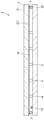
- FIG. 1 is a cross-sectional view of a glass panel unit in the glass panel manufacturing method according to the first embodiment of the present invention.
- FIG. 2 is a partially broken plan view of the above glass panel unit.
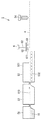
- FIG. 3 is a configuration diagram of a manufacturing apparatus used in the glass panel manufacturing method described above.
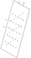
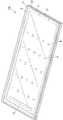
- FIG. 4 is a perspective view of a second glass panel manufactured by the same glass panel manufacturing method.
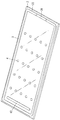
- FIG. 5 is a perspective view of the second glass panel after completion of the second step of the arrangement step of the unit manufacturing step.
- FIG. 6 is a perspective view of the first glass panel and the second glass panel for explaining the fifth step.
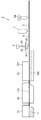
- FIG. 7 is a temperature time chart illustrating the first melting process, the exhaust process, and the second melting process in the sealing process of the unit manufacturing process.
- FIG. 1 is a cross-sectional view of a glass panel unit in the glass panel manufacturing method according to the first embodiment of the present invention.
- FIG. 2 is a partially broken plan view of the above glass panel unit.
- FIG. 8 is a perspective view of the temporary assembly after the assembly process is completed.
- FIG. 9 is a configuration diagram of a manufacturing apparatus used in the glass panel manufacturing method according to the second embodiment of the present invention.
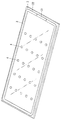
- FIG. 10 is a perspective view of a glass panel (second glass panel) manufactured by the glass panel manufacturing method described above.
- FIG. 11 is a configuration diagram of a manufacturing apparatus used in the glass panel manufacturing method according to the third embodiment of the present invention.
- FIG. 12 is a configuration diagram of a manufacturing apparatus used in the glass panel manufacturing method according to the fourth embodiment of the present invention.
- the following first to fourth embodiments relate to a method and an apparatus for manufacturing a glass panel for a glass panel unit.
- the glass panel unit 1 (finished product) includes a pair of glass panels 2, a frame body 3, an internal space 10, and a spacer 4 that are opposed to each other with a predetermined interval. Prepare.
- the pair of glass panels 2 includes a first glass panel 21 and a second glass panel 22 that face each other with a predetermined interval.
- the frame 3 is disposed between the pair of glass panels 2, that is, the first glass panel 21 and the second glass panel 22, and airtightly joins the first glass panel 21 and the second glass panel 22. Thereby, the internal space 10 enclosed by the 1st glass panel 21, the 2nd glass panel 22, and the frame 3 is formed.
- the spacer 4 is arrange
- FIG. . 1st embodiment has the characteristics in the manufacturing method and manufacturing apparatus 5 (refer FIG. 3) in a glass panel manufacturing process. First, the manufacturing method and the manufacturing apparatus 5 of the glass panel 2 in a glass panel manufacturing process are demonstrated based on FIG.
- the manufacturing method (manufacturing process) of the glass panel 2 includes a melting process, a spreading process, a slow cooling process, a cutting process, and a spacer arranging process.
- the glass panel 2 manufacturing apparatus 5 includes a melting tank 51, a float bath 52, a slow cooling device 53, a cutting device 54, and a spacer arranging device 6.
- the melting step is a step of melting the glass raw material 11 to generate molten glass.
- the melting step is performed in a melting tank 51 for melting the glass raw material 11.
- the melting tank 51 constitutes a melting device together with a heating means for melting the glass raw material 11 and other equipment.
- the raw material 11 for glass sand, soda ash (sodium carbonate), dolomite, limestone, sodium sulfate (sodium sulfate) and the like are used. Further, as the glass raw material 11, a colorant, a refining agent, and a material for adjusting physical or chemical properties of the glass may be added as appropriate.
- the glass raw material 11 is heated to about 1500 to 1600 ° C. by a heating means to be melted into molten glass and stored in the melting tank 51.
- the extending process is a process of generating the glass sheet 110 by extending the molten glass melted in the melting process on the molten metal.
- the extending process is performed in a float bath 52 that extends the molten glass on the molten metal.
- the float bath 52 constitutes a float bath device together with heating means for melting metal and other devices.
- the float bath 52 stores molten tin (not shown), and the molten glass spreads in a plate shape on the upper surface and gradually solidifies. Thereby, the glass sheet 110 with a uniform thickness and an extremely flat surface can be manufactured.
- the slow cooling step is a step in which the glass sheet 110 is pulled out and slowly cooled.
- the slow cooling process is performed in a slow cooling device 53 that draws the glass sheet 110 from the float bath 52 and cools it slowly.
- the slow cooling device 53 includes a furnace 531 and a temperature adjusting device that adjusts the atmospheric temperature in the furnace 531. A well-known thing can be utilized suitably for a temperature control apparatus.
- the slow cooling device 53 includes other necessary equipment such as a roll 532 and its driving means, and conveys the glass sheet 110 placed on the roll 532.
- the length of the furnace 531 (length in the conveyance direction of the glass sheet 110) is several tens of meters, and the width (length in the direction orthogonal to the conveyance direction of the glass sheet 110) is about 10 m, but is not particularly limited.
- the glass sheet 110 has a temperature of about 600 to 750 ° C. at the upstream end and about 200 to 400 ° C. at the downstream end, and during that time, the temperature decreases linearly or nonlinearly from the upstream side to the downstream side. I will do it.
- the cutting step is a step of cutting the gradually cooled glass sheet 110.
- a cutting process is performed in the cutting device 54 which cut
- the cutting device 54 includes other equipment such as a cutting blade and a driving means. As such a cutting device 54, a well-known thing can be utilized suitably.
- the melting tank 51, the float bath 52, the slow cooling device 53, and the cutting device 54 are provided in order from the upstream side.
- upstream and downstream mean upstream and downstream in the flow of glass. That is, the molten glass melted in the melting step is then flowed to the float bath 52, then sent to the slow cooling device 53, and then sent to the cutting device 54. The cooling process and the cutting process are performed in this order.
- the glass panel 2 manufacturing apparatus 5 further includes a melting device having a melting tank 51, a float bath device having a float bath 52, a slow cooling device 53, and a control device for controlling the cutting device 54.
- the control device includes, for example, a so-called microcomputer that operates according to a program. As such a control device, known devices can be used as appropriate.
- the above-described glass panel 2 manufacturing method (manufacturing method not having a spacer arranging step described later) and manufacturing apparatus (manufacturing device not having a spacer arranging device 6 described later) are known so-called float glass manufacturing methods and manufacturing apparatuses. Generally provided in common. In the first embodiment, known general variations of such a float glass manufacturing method and manufacturing apparatus can be used as appropriate.
- the first embodiment is characterized by further comprising a spacer arrangement step.
- positioning process is a process of arrange
- the spacer arranging step is performed in the spacer arranging device 6 that arranges the spacer 4 on the glass sheet 110.
- the spacer arrangement device 6 is provided on the downstream side of the slow cooling device 53 and on the upstream side of the cutting device 54.
- the spacer arrangement device 6 includes a punching die 61 and a punch 62 in the first embodiment.
- the punching die 61 is located above the glass sheet 110 and has a through hole 611.
- a sheet 63 is placed on the upper surface of the punching die 61 so as to cover the through hole 611.
- the material of the sheet 63 is the same as that of the spacer 4, the thickness is the same as the thickness of the spacer 4, and the area is wider than the area of the spacer 4.
- the punch 62 is located above the punching die 61.
- the punch 62 has a columnar shape protruding downward, and punches the sheet 63 covered with the punching die 61 downward through the through hole 611.
- the spacer arrangement device 6 is appropriately provided with necessary equipment such as a driving means for driving the punch 62, and is controlled by the control device described above.
- a known device including such a punching die 61 and a punch 62 can be used as appropriate.
- a so-called chip mounter can be used.
- the spacer arrangement device 6 is not limited to a device provided with the punching die 61 and the punch 62 and a chip mounter.
- a so-called pick and place device may be provided that picks up the stocked spacer 4 with a suction head and lowers it to a desired position on the glass sheet.
- the glass raw material 11 is melted in the melting step to generate a molten glass, and then the molten glass is melted in the extending step.
- the glass sheet 110 is produced by extending the glass sheet 110, and then the glass sheet 110 is gradually cooled in the slow cooling step.
- the spacer 4 is arrange
- the 2nd glass panel 22 by which the spacer 4 was provided in the surface is obtained.
- the spacers 4 are not arranged on the first glass panel 21. That is, the 1st glass panel 21 is manufactured by the conventional glass panel manufacturing process which does not have a spacer arrangement
- the first glass panel 21 has a coating 211 such as a so-called Low-E film on the surface facing the second glass panel 22, The coating 211 may not be provided.
- the unit manufacturing process includes an arrangement process, an assembly process, a sealing process, and a removal process.
- Arrangement step is a step of forming the first glass panel 21, the second glass panel 22, the frame 3, the internal space 10, the exhaust port, and the gas adsorber 12.
- the arranging step has a first step to a fourth step.
- the first step is a step of preparing the first glass panel 21 and the second glass panel 22 (glass panel preparation step).
- the glass panel 2 provided with the spacer 4 on the above-described surface shown in FIG. 4 is used, and as the first glass panel 21, the glass panel 2 without the spacer 4 provided on the surface is used. .
- the 2nd process is a process (sealing material formation process) which forms a seal (frame 3), as shown in FIG.
- the material of the frame 3 thermal adhesive
- the material of the frame 3 thermal adhesive
- a low step portion 31 having a thickness smaller than the thickness of other portions is formed in a part of the frame 3.
- the low step portion 31 forms an exhaust port for a temporary assembly product.
- the exhaust port may not be formed by the low step portion 31.
- an exhaust hole may be provided in one of the first glass panel 21 or the second glass panel 22.
- an exhaust pipe having an inner diameter larger than that of the exhaust holes is formed in the exhaust port by a well-known method using glass welding or a molten metal as a welding member. Connecting.
- a vacuum space may be formed by performing exhaust through the exhaust pipe and performing a so-called chip-off for sealing the space by sealing the tip of the exhaust pipe after the exhaust process.
- the third step is a step of forming the gas adsorber 12 (gas adsorber forming step).
- the gas adsorber 12 is formed by applying a solution in which getter powder is dispersed to a predetermined position of the second glass panel 22 and drying the solution.
- the method of forming the gas adsorber 12 is not limited to this, and the gas adsorber 12 containing the getter powder may be formed in advance in a tablet-shaped pellet and placed at a predetermined position on the second glass panel 22. good. In that case, the recessed part which shaved the surface of the 2nd glass panel 22 according to the tablet shape may be formed, and the gas adsorption body 12 may be inserted in this recessed part.
- the second glass panel 22 in which the frame 3, the gas adsorber 12, and the plurality of spacers 4 are formed as shown in FIG. 5 is obtained.
- the fourth step is a step of arranging the first glass panel 21 and the second glass panel 22 (superposition step). As shown in FIG. 6, in the fourth step, the first glass panel 21 and the second glass panel 22 are arranged so that the first glass panel 21 and the second glass panel 22 are parallel and opposed to each other, Superimposed.
- the assembly process is a process (first melting process) in which the first glass panel 21 and the second glass panel 22 are hermetically joined by the frame 3.
- the first glass panel 21 and the second glass are melted once at a predetermined temperature (first melting temperature) Tm1 equal to or higher than the softening point of the thermal adhesive.
- the panel 22 is airtightly joined.
- the first glass panel 21 and the second glass panel 22 are disposed in the chamber portion and heated at the first melting temperature Tm1 for a predetermined time (first melting time) tm1.
- the temporary assembly 100 shown in FIG. 8 is obtained by the assembly process (first melting process) described above.
- the second melting step heats the thermal adhesive once at a predetermined temperature (second melting temperature) Tm2 above the softening point for a predetermined time (second melting time) tm2, thereby melting the first glass panel 21 and The second glass panel 22 is pressed to atmospheric pressure, the thermal adhesive is crushed, and the low step portion 31 is closed. Thereby, the seal
- the first melting temperature Tm1 is lower than the second melting temperature Tm2.
- the internal space 10 is evacuated while maintaining the vacuum space.
- the temporary assembly 100 is subjected to a predetermined process to obtain the glass panel unit 1 (finished product) shown in FIGS.
- the spacer arrangement step in the glass panel manufacturing process by providing the spacer arrangement step in the glass panel manufacturing process, the arrangement of the spacer 4 on the glass panel 2 is performed before cutting the continuously manufactured glass sheet 110. Is called.
- the spacer 4 can be arranged as part of the production of the glass sheet 110 that is continuously produced, and the spacer 4 is arranged for each cut glass panel 2 as in the case of arranging the spacer 4 after cutting. The troublesome work of arranging the spacers 4 after aligning the arrangement positions of 4 becomes unnecessary.
- the spacer 4 or the frame 3 what mixed the organic binder with the low melting glass may be apply
- FIG. The temperature of this reheating step may be reheated to a boiling point or decomposition point of the organic binder or higher (about 100 to 200 ° C.) if the purpose is to remove the organic binder. If the glass panel and the spacer 4 or the frame 3 are fused, they may be reheated at a temperature equal to or higher than the melting point of the low-melting glass (for example, 400 ° C. or higher).
- the pretreatment of the spacer 4 or the frame 3 can be performed before cutting, so that the glass panel unit can be efficiently manufactured.
- the material of the spacer 4 is not limited to glass, but may be, for example, metal or resin.
- the cutting step in the first embodiment, it is provided until the cutting step, and includes a frame body arranging step for arranging the frame body 3 on the glass sheet 110.
- the frame arrangement process is performed in a frame arrangement apparatus 7 that arranges the frame 3 on the glass sheet 110. That is, in 2nd embodiment, the manufacturing apparatus 5 of the glass panel 2 for the glass panel unit 1 is further provided with the frame arrangement
- FIG. The frame arrangement device 7 is provided on the downstream side of the spacer arrangement device 6 and on the upstream side of the cutting device 54, but may be provided on the upstream side of the spacer arrangement device 6 and on the downstream side of the slow cooling device 53. .
- the frame arrangement device 7 includes a dispenser similar to that used in the second step (sealing material forming step) of the arrangement steps of the unit manufacturing process in the first embodiment, and the frame body as in the sealing material forming step. 3 material (thermal adhesive) is applied on the second glass panel 22.
- the 2nd process (sealing material formation process) of the arrangement processes of a unit manufacturing process is omitted. That is, only the 1st process (glass panel preparation process), the 3rd process (gas adsorption body formation process), and the 4th process (superposition process) are performed as an arrangement process.
- the glass raw material 11 is melted in the melting step to generate molten glass, and then the molten glass is melted in the extending step.
- the glass sheet 110 is produced by spreading on the metal, and then the glass sheet 110 is gradually cooled in a slow cooling step.
- the spacer 4 is arrange
- the frame 3 is arrange
- the glass sheet 110 is cut
- the 2nd glass panel 22 by which the spacer 4 and the frame 3 were provided in the surface is obtained.
- the spacer 4 and the frame 3 are not arranged. That is, the 1st glass panel 21 is manufactured by the conventional glass panel manufacturing process which does not have a spacer arrangement
- the arrangement of the frame body 3 on the glass panel 2 is a continuous cutting of the glass sheet 110 that is manufactured. Done before. For this reason, arrangement
- the spacer arrangement step is provided after the slow cooling step and before the cutting step.
- it has a spacer arrangement
- positioning process is a process of arrange
- the spacer arrangement apparatus 6 for performing a spacer arrangement process is provided in the slow cooling apparatus 53, as shown in FIG.
- the spacer placement device 6 is a device that places the spacer 4 by dripping hot-melt glass serving as the material of the spacer 4.
- the hot-melt glass used as the material of the spacer 4 is dropped onto the glass sheet 110 from the spacer arrangement device 6 and cooled to form the spacer 4 at a predetermined position.
- the glass raw material 11 is melted in the melting step to generate molten glass, and then the molten glass is melted in the extending step.
- the glass sheet 110 is produced by spreading on the metal, and then the spacer 4 is arranged on the glass sheet 110 by the spacer arrangement process while the glass sheet 110 is gradually cooled in the slow cooling process. Thereafter, the glass sheet 110 is cut by a cutting process. Thereby, as shown in FIG. 4, the 2nd glass panel 22 by which the spacer 4 was provided in the surface is obtained.
- the subsequent unit manufacturing process is the same as in the first embodiment.
- the spacer 4 can be easily formed while saving energy by using the residual heat of the slow cooling step by having the spacer arranging step in the slow cooling step.
- the difference between the melting point of the hot-melt glass used as the material of the spacer 4 and the temperature of the glass sheet 110 at the position where the hot-melt glass is dropped from the spacer arrangement device 6 is preferably 100 ° C. or less.
- the hot-melt glass is preferably dropped onto the glass sheet 110 from the spacer arrangement device 6 in the region where the temperature in the furnace 531 is 700 ° C. to 600 ° C.
- the dropping position is a position where the temperature of the glass sheet 110 is lower than the melting point of the hot-melt glass, the glass sheet 110 may be cracked due to the temperature difference, and if it is higher than that, the spacer 4 is crushed. There is a possibility that.
- the spacer arrangement step is provided after the slow cooling step and before the cutting step.
- it has a spacer arrangement
- This spacer placement step is a step of placing the spacer 4 by dropping hot-melt glass, and this is the same as in the third embodiment, and the spacer placement device 6 and its placement position are also the same as in the third embodiment. It is the same.
- the glass raw material 11 is melted in the melting step to generate molten glass, and then the molten glass is melted in the extending step.
- the glass sheet 110 is produced by spreading on the metal, and then the spacer 4 is arranged on the glass sheet 110 by the spacer arrangement process while the glass sheet 110 is gradually cooled in the slow cooling process.
- the frame 3 is arrange
- the 2nd glass panel 22 (refer FIG. 10) by which the spacer 4 and the frame 3 were provided in the surface is obtained.
- the subsequent unit manufacturing process is the same as in the third embodiment.
- the spacer 4 can be easily formed by using the remaining heat of the slow cooling step and saving energy by using the spacer placement step in the slow cooling step.
- the temperature of the glass sheet 110 at the position where the hot-melt glass serving as the material of the spacer 4 is dropped changes the position where the hot-melt glass serving as the material of the spacer 4 is dropped (position in the transport direction of the glass sheet 110). Is adjustable.
- the method for manufacturing the glass panel 2 for the glass panel unit 1 includes a melting step, a spreading step, A slow cooling process, a cutting process, and a spacer arrangement process are provided.
- the glass panel unit 1 includes a pair of glass panels 2, a frame body 3, an internal space 10, and a spacer 4 that face each other with a predetermined interval.
- the frame 3 is arrange
- the internal space 10 is surrounded by a pair of glass panels 2 and a frame body 3.
- the spacer 4 is disposed in the internal space 10 and contacts the pair of glass panels 2.
- the melting step is a step of generating molten glass by melting the glass raw material 11.
- the extending step is a step of generating the glass sheet 110 by extending the molten glass on the molten metal.
- the slow cooling step is a step in which the glass sheet 110 is pulled out and slowly cooled.
- the cutting step is a step of cutting the slowly cooled glass sheet 110.
- positioning process is a process of arrange
- positioning process Done before cutting.
- the spacer 4 can be arranged as part of the production of the glass sheet 110 that is continuously produced, and the spacer 4 is arranged for each cut glass panel 2 as in the case of arranging the spacer 4 after cutting. The troublesome work of arranging the spacers 4 after aligning the arrangement positions of 4 becomes unnecessary.
- the manufacturing method of the glass panel 2 for the glass panel unit 1 of the 2nd aspect which concerns on this invention is an additional thing, By the combination with the manufacturing method of the glass panel 2 for the glass panel unit 1 of a 1st aspect Realized.
- the manufacturing method of the glass panel 2 for the glass panel unit 1 of the 2nd aspect is provided by the cutting process, and is provided with the frame body arrangement
- positioning to the glass panel 2 of the frame 3 is continuously manufactured by further providing the frame arrangement
- the manufacturing method of the glass panel 2 for the glass panel unit 1 of the 3rd aspect which concerns on this invention is additional, and manufacture of the glass panel 2 for the glass panel unit 1 of a 1st aspect or a 2nd aspect. Realized by a combination of methods.
- the manufacturing method of the glass panel 2 for the glass panel unit 1 of the 3rd aspect has a spacer arrangement
- the spacer arrangement step is included in the slow cooling step, thereby making it possible to save energy by utilizing the residual heat in the slow cooling step. 4 can be formed easily.
- the manufacturing apparatus 5 of the glass panel 2 for the glass panel unit 1 includes a melting tank 51, a float bath 52, a slow cooling device 53, and a cutting device 54. Prepare in order from the upstream side of the flow.
- the manufacturing apparatus 5 includes a spacer arrangement device 6 provided on the upstream side of the cutting device 54.
- the glass panel unit 1 includes a pair of glass panels 2, a frame body 3, an internal space 10, and a spacer 4 that face each other with a predetermined interval.
- the frame 3 is arrange
- the internal space 10 is surrounded by a pair of glass panels 2 and a frame body 3.
- the spacer 4 is disposed in the internal space 10 and contacts the pair of glass panels 2.
- the melting tank 51 is an apparatus that generates molten glass by melting the glass raw material 11.
- the float bath 52 is an apparatus that generates a glass sheet 110 by spreading molten glass on a molten metal.
- the slow cooling device 53 is a device that pulls out the glass sheet 110 and slowly cools it.
- the cutting device 54 is a device that cuts the slowly cooled glass sheet 110.
- the spacer placement device 6 is a device for placing the spacer 4 on the glass sheet 110.
- the spacer 4 can be arranged as part of the production of the glass sheet 110 that is continuously produced, and the spacer 4 is arranged for each cut glass panel 2 as in the case of arranging the spacer 4 after cutting. The troublesome work of arranging the spacers 4 after aligning the arrangement positions of 4 becomes unnecessary.
- the manufacturing apparatus 5 of the glass panel 2 for the glass panel unit 1 of the 2nd aspect which concerns on this invention is an additional thing, and the manufacturing apparatus 5 of the glass panel 2 for the glass panel unit 1 of a 1st aspect Realized by combination.
- the manufacturing apparatus 5 of the glass panel 2 for the glass panel unit 1 according to the second aspect includes a frame body arranging device 7 that arranges the frame body 3 on the glass sheet 110.
- the manufacturing apparatus 5 of the glass panel 2 for the glass panel unit 1 of the second aspect by further providing the frame body arranging device 7, the arrangement of the frame body 3 on the glass panel 2 is continuously produced. This is performed before the glass sheet 110 to be cut. For this reason, arrangement
- the manufacturing apparatus 5 of the glass panel 2 for the glass panel unit 1 of the 3rd aspect which concerns on this invention is an additional thing, and is the glass panel 2 for the glass panel unit 1 of the 1st aspect or the 2nd aspect. This is realized by a combination with the manufacturing apparatus 5.
- the spacer arrangement device 6 is provided in the slow cooling device 53. It is an apparatus which arrange
- the manufacturing apparatus 5 of the glass panel 2 for the glass panel unit 1 of the third aspect by providing the spacer arrangement step in the slow cooling device 53, the remaining heat of the slow cooling step is used to save energy.
- the spacer 4 can be easily formed.
Abstract
The present invention addresses the problem of providing a method and apparatus for manufacturing a glass panel for a glass panel unit which do not require the operation of adjusting the placement positions of spacers for each cut glass panel and then placing the spacers. The method for manufacturing a glass panel for a glass panel unit includes a melting step, a spreading step, an annealing step, a cutting step, and a spacer placing step. The spacer placing step is provided before the cutting step, is performed by a spacer placing device (6), and is a step of placing spacers (4) on a glass sheet (110).
Description
本発明は、ガラスパネルユニット用のガラスパネルの製造方法および製造装置に関する。
The present invention relates to a method and apparatus for producing a glass panel for a glass panel unit.
従来、一対のガラスパネルと、一対のガラスパネル間に配置されて一対のガラスパネルを気密に接合する枠体と、一対のガラスパネルと枠体とで囲まれる内部空間内に配置されるスペーサと、を備えるガラスパネルユニットが知られている(例えば特許文献1参照)。
Conventionally, a pair of glass panels, a frame body disposed between the pair of glass panels and hermetically joining the pair of glass panels, and a spacer disposed in an internal space surrounded by the pair of glass panels and the frame body, Are known (see, for example, Patent Document 1).
この従来のガラスパネルユニットの製造は、所定の大きさに切断された一対のガラスパネルを準備し、枠体およびスペーサを一方のガラスパネルに配置して、他方のガラスパネルと重ね合わせる。そして、内部空間を排気し、加熱して枠体を一旦軟化させることにより一対のガラスパネルを気密に接合し、ガラスパネルユニットの完成品を得るものであった。
In the manufacture of this conventional glass panel unit, a pair of glass panels cut into a predetermined size is prepared, a frame body and a spacer are arranged on one glass panel, and the other glass panel is overlapped. Then, the internal space is evacuated and heated to soften the frame body, thereby joining the pair of glass panels in an airtight manner to obtain a finished glass panel unit.
上記従来のガラスパネルユニットにあっては、スペーサのガラスパネルへの配置は、切断されたガラスパネル毎にスペーサの配置位置を合せてからスペーサを配置する、という面倒な作業となっていた。
In the conventional glass panel unit described above, the arrangement of the spacers on the glass panel is a troublesome work of arranging the spacers after aligning the arrangement positions of the spacers for each cut glass panel.
本発明は、切断されたガラスパネル毎にスペーサの配置位置を合せてからスペーサを配置する作業が不要となるガラスパネルユニット用のガラスパネルの製造方法および製造装置を得ることを目的とする。
An object of the present invention is to obtain a glass panel manufacturing method and a manufacturing apparatus for a glass panel unit that do not require the operation of arranging the spacer after aligning the arrangement position of the spacer for each cut glass panel.
本発明は、ガラスパネルユニット用のガラスパネルの製造方法である。前記ガラスパネルユニットは、所定の間隔をあけて対向する一対の前記ガラスパネルと、枠体と、内部空間と、スペーサと、を備える。前記枠体は、一対の前記ガラスパネル間に配置されて一対の前記ガラスパネルを気密に接合する。前記内部空間は、一対の前記ガラスパネルと前記枠体とで囲まれる。前記スペーサは、前記内部空間内に配置されて一対の前記ガラスパネルに接触する。前記製造方法は、溶融工程と、延展工程と、徐冷工程と、切断工程と、スペーサ配置工程と、を備える。前記溶融工程は、ガラスの原料を溶融させて溶融ガラスを生成する工程である。前記延展工程は、前記溶融ガラスを溶融した金属上に延展させてガラスシートを生成する工程である。前記徐冷工程は、前記ガラスシートを引き出して徐冷させる工程である。前記切断工程は、徐冷された前記ガラスシートを切断する工程である。前記スペーサ配置工程は、前記切断工程までに設けられ、前記ガラスシート上に前記スペーサを配置する工程である。
The present invention is a method for producing a glass panel for a glass panel unit. The glass panel unit includes a pair of the glass panels facing each other with a predetermined interval, a frame, an internal space, and a spacer. The said frame is arrange | positioned between a pair of said glass panels, and joins a pair of said glass panel airtightly. The internal space is surrounded by a pair of the glass panel and the frame. The spacer is disposed in the internal space and contacts the pair of glass panels. The manufacturing method includes a melting step, a spreading step, a slow cooling step, a cutting step, and a spacer arranging step. The melting step is a step of producing a molten glass by melting a glass raw material. The extending step is a step of generating a glass sheet by extending the molten glass on a molten metal. The slow cooling step is a step of slowly cooling the glass sheet by drawing it out. The cutting step is a step of cutting the slowly cooled glass sheet. The said spacer arrangement | positioning process is a process provided by the said cutting process and arrange | positioning the said spacer on the said glass sheet.
また本発明は、ガラスパネルユニット用のガラスパネルの製造装置である。前記ガラスパネルユニットは、所定の間隔をあけて対向する一対の前記ガラスパネルと、枠体と、内部空間と、スペーサと、を備える。前記枠体は、一対の前記ガラスパネル間に配置されて一対の前記ガラスパネルを気密に接合する。前記内部空間は、一対の前記ガラスパネルと前記枠体とで囲まれる。前記スペーサは、前記内部空間内に配置されて一対の前記ガラスパネルに接触する。前記製造装置は、溶融槽と、フロートバスと、徐冷装置と、切断装置と、を前記ガラスの流れの上流側より順に備える。前記製造装置は、前記切断装置の前記上流側に設けられるスペーサ配置装置を備える。前記溶融槽は、ガラスの原料を溶融させて溶融ガラスを生成する装置である。前記フロートバスは、前記溶融ガラスを溶融した金属上に延展させてガラスシートを生成する装置である。前記徐冷装置は、前記フロートバスより前記ガラスシートを引き出して徐冷させる装置である。前記切断装置は、徐冷された前記ガラスシートを切断する装置である。前記スペーサ配置装置は、前記ガラスシート上に前記スペーサを配置する装置である。
The present invention is also a glass panel manufacturing apparatus for a glass panel unit. The glass panel unit includes a pair of the glass panels facing each other with a predetermined interval, a frame, an internal space, and a spacer. The said frame is arrange | positioned between a pair of said glass panels, and joins a pair of said glass panel airtightly. The internal space is surrounded by a pair of the glass panel and the frame. The spacer is disposed in the internal space and contacts the pair of glass panels. The said manufacturing apparatus is equipped with a melting tank, a float bath, a slow cooling apparatus, and a cutting device in order from the upstream of the flow of the said glass. The manufacturing apparatus includes a spacer arrangement device provided on the upstream side of the cutting device. The said melting tank is an apparatus which melt | dissolves the raw material of glass and produces | generates molten glass. The float bath is an apparatus that generates a glass sheet by extending the molten glass on a molten metal. The slow cooling device is a device that draws out the glass sheet from the float bath and slowly cools it. The cutting device is a device that cuts the slowly cooled glass sheet. The said spacer arrangement | positioning apparatus is an apparatus which arrange | positions the said spacer on the said glass sheet.
以下の第一実施形態~第四実施形態は、ガラスパネルユニット用のガラスパネルの製造方法および製造装置に関する。
The following first to fourth embodiments relate to a method and an apparatus for manufacturing a glass panel for a glass panel unit.
まず、第一実施形態のガラスパネルユニット用のガラスパネルの製造方法および製造装置について、図1~図8に基いて説明する。図1、図2に示すように、ガラスパネルユニット1(完成品)は、所定の間隔をあけて対向する一対のガラスパネル2と、枠体3と、内部空間10と、スペーサ4と、を備える。
First, a method and apparatus for manufacturing a glass panel for a glass panel unit according to the first embodiment will be described with reference to FIGS. As shown in FIGS. 1 and 2, the glass panel unit 1 (finished product) includes a pair of glass panels 2, a frame body 3, an internal space 10, and a spacer 4 that are opposed to each other with a predetermined interval. Prepare.
一対のガラスパネル2は、所定の間隔をあけて対向する第1ガラスパネル21と、第2ガラスパネル22と、を備える。
The pair of glass panels 2 includes a first glass panel 21 and a second glass panel 22 that face each other with a predetermined interval.
枠体3は、一対のガラスパネル2すなわち第1ガラスパネル21と第2ガラスパネル22との間に配置されて、第1ガラスパネル21と第2ガラスパネル22とを気密に接合する。これにより、第1ガラスパネル21と第2ガラスパネル22と枠体3とで囲まれる内部空間10が形成される。
The frame 3 is disposed between the pair of glass panels 2, that is, the first glass panel 21 and the second glass panel 22, and airtightly joins the first glass panel 21 and the second glass panel 22. Thereby, the internal space 10 enclosed by the 1st glass panel 21, the 2nd glass panel 22, and the frame 3 is formed.
スペーサ4は、内部空間10内に配置されて、第1ガラスパネル21と第2ガラスパネル22とに接触し、第1ガラスパネル21と第2ガラスパネル22との間隔を所定の間隔に保つ。
The spacer 4 is arrange | positioned in the interior space 10, contacts the 1st glass panel 21 and the 2nd glass panel 22, and maintains the space | interval of the 1st glass panel 21 and the 2nd glass panel 22 at a predetermined space | interval.
このようなガラスパネルユニット1は、ガラスパネル2を製造するガラスパネル製造工程と、製造されたガラスパネル2を用いてガラスパネルユニット1(完成品)を組み上げるユニット製造工程と、を経て製造される。第一実施形態は、ガラスパネル製造工程における製造方法および製造装置5(図3参照)に特徴を有するものである。まず、ガラスパネル製造工程におけるガラスパネル2の製造方法および製造装置5について図3に基いて説明する。
Such a glass panel unit 1 is manufactured through the glass panel manufacturing process which manufactures the glass panel 2, and the unit manufacturing process which assembles the glass panel unit 1 (finished product) using the manufactured glass panel 2. FIG. . 1st embodiment has the characteristics in the manufacturing method and manufacturing apparatus 5 (refer FIG. 3) in a glass panel manufacturing process. First, the manufacturing method and the manufacturing apparatus 5 of the glass panel 2 in a glass panel manufacturing process are demonstrated based on FIG.
ガラスパネル2の製造方法(製造工程)は、溶融工程と、延展工程と、徐冷工程と、切断工程と、スペーサ配置工程と、を備える。また、ガラスパネル2の製造装置5は、溶融槽51と、フロートバス52と、徐冷装置53と、切断装置54と、スペーサ配置装置6と、を備える。
The manufacturing method (manufacturing process) of the glass panel 2 includes a melting process, a spreading process, a slow cooling process, a cutting process, and a spacer arranging process. The glass panel 2 manufacturing apparatus 5 includes a melting tank 51, a float bath 52, a slow cooling device 53, a cutting device 54, and a spacer arranging device 6.
溶融工程は、ガラスの原料11を溶融させて溶融ガラスを生成する工程である。溶融工程は、ガラスの原料11を溶融させる溶融槽51において行われる。溶融槽51は、ガラスの原料11を溶融させるための加熱手段およびその他の機器と合わせて溶融装置を構成している。
The melting step is a step of melting the glass raw material 11 to generate molten glass. The melting step is performed in a melting tank 51 for melting the glass raw material 11. The melting tank 51 constitutes a melting device together with a heating means for melting the glass raw material 11 and other equipment.
ガラスの原料11としては、砂、ソーダ灰(炭酸ナトリウム)、ドロマイト、石灰岩、芒硝(硫酸ナトリウム)等が使用される。また、ガラスの原料11として、この他にも着色剤、精製剤、ガラスの物理的または化学的特性を調整する材料を適宜添加してもよい。ガラスの原料11は、加熱手段により約1500~1600℃に加熱されて溶融して溶融ガラスとなり、溶融槽51に貯留される。
As the raw material 11 for glass, sand, soda ash (sodium carbonate), dolomite, limestone, sodium sulfate (sodium sulfate) and the like are used. Further, as the glass raw material 11, a colorant, a refining agent, and a material for adjusting physical or chemical properties of the glass may be added as appropriate. The glass raw material 11 is heated to about 1500 to 1600 ° C. by a heating means to be melted into molten glass and stored in the melting tank 51.
延展工程は、溶融工程において溶融した溶融ガラスを溶融した金属上に延展させてガラスシート110を生成する工程である。延展工程は、溶融ガラスを溶融した金属上に延展させるフロートバス52において行われる。フロートバス52は、金属を溶融させるための加熱手段およびその他の機器と合わせてフロートバス装置を構成している。
The extending process is a process of generating the glass sheet 110 by extending the molten glass melted in the melting process on the molten metal. The extending process is performed in a float bath 52 that extends the molten glass on the molten metal. The float bath 52 constitutes a float bath device together with heating means for melting metal and other devices.
第一実施形態では、フロートバス52は、溶融した錫(不図示)が貯留されており、その上面に溶融ガラスが板状に広がって徐々に固まっていく。これにより、厚さが均一で表面が極めて平坦なガラスシート110が製造可能である。
In the first embodiment, the float bath 52 stores molten tin (not shown), and the molten glass spreads in a plate shape on the upper surface and gradually solidifies. Thereby, the glass sheet 110 with a uniform thickness and an extremely flat surface can be manufactured.
徐冷工程は、ガラスシート110を引き出して徐冷させる工程である。徐冷工程は、フロートバス52よりガラスシート110を引き出して徐冷させる徐冷装置53において行われる。徐冷装置53は、炉531と、炉531内の雰囲気温度を調節する温度調節装置を備えている。温度調節装置は、公知のものが適宜利用可能である。
The slow cooling step is a step in which the glass sheet 110 is pulled out and slowly cooled. The slow cooling process is performed in a slow cooling device 53 that draws the glass sheet 110 from the float bath 52 and cools it slowly. The slow cooling device 53 includes a furnace 531 and a temperature adjusting device that adjusts the atmospheric temperature in the furnace 531. A well-known thing can be utilized suitably for a temperature control apparatus.
徐冷装置53は、ロール532およびその駆動手段等の他の必要な機器を備え、ロール532上に載置したガラスシート110を搬送する。炉531の長さ(ガラスシート110の搬送方向における長さ)は数十m、幅(ガラスシート110の搬送方向に直交する方向における長さ)は約10mであるが、特に限定されない。炉531内では、ガラスシート110は、上流端では約600~750℃、下流端では約200~400℃となっており、その間は、上流側から下流側に向けて線形または非線形に温度が下降していく。
The slow cooling device 53 includes other necessary equipment such as a roll 532 and its driving means, and conveys the glass sheet 110 placed on the roll 532. The length of the furnace 531 (length in the conveyance direction of the glass sheet 110) is several tens of meters, and the width (length in the direction orthogonal to the conveyance direction of the glass sheet 110) is about 10 m, but is not particularly limited. In the furnace 531, the glass sheet 110 has a temperature of about 600 to 750 ° C. at the upstream end and about 200 to 400 ° C. at the downstream end, and during that time, the temperature decreases linearly or nonlinearly from the upstream side to the downstream side. I will do it.
切断工程は、徐冷されたガラスシート110を切断する工程である。切断工程は、徐冷されたガラスシート110を切断する切断装置54において行われる。切断装置54は、たとえば切断刃および駆動手段等の他の機器を備えたものである。このような切断装置54は、公知のものが適宜利用可能である。
The cutting step is a step of cutting the gradually cooled glass sheet 110. A cutting process is performed in the cutting device 54 which cut | disconnects the slowly cooled glass sheet 110. FIG. The cutting device 54 includes other equipment such as a cutting blade and a driving means. As such a cutting device 54, a well-known thing can be utilized suitably.
ここで、溶融槽51、フロートバス52、徐冷装置53および切断装置54は、上流側より順に設けられる。ここで、上流および下流とは、ガラスの流れにおける上流および下流をいうものとする。すなわち、溶融工程において溶融した溶融ガラスは、その後、フロートバス52へと流れ、その後、徐冷装置53へと送られ、その後、切断装置54へと送られるもので、溶融工程、延展工程、徐冷工程、切断工程の順に実行される。
Here, the melting tank 51, the float bath 52, the slow cooling device 53, and the cutting device 54 are provided in order from the upstream side. Here, upstream and downstream mean upstream and downstream in the flow of glass. That is, the molten glass melted in the melting step is then flowed to the float bath 52, then sent to the slow cooling device 53, and then sent to the cutting device 54. The cooling process and the cutting process are performed in this order.
ガラスパネル2の製造装置5は、第一実施形態においてはさらに、溶融槽51を有する溶融装置、フロートバス52を有するフロートバス装置、徐冷装置53および切断装置54を制御する制御装置を備える。制御装置は、たとえば、プログラムに従って動作するいわゆるマイクロコンピュータを備える。このような制御装置は、公知のものが適宜利用可能である。
In the first embodiment, the glass panel 2 manufacturing apparatus 5 further includes a melting device having a melting tank 51, a float bath device having a float bath 52, a slow cooling device 53, and a control device for controlling the cutting device 54. The control device includes, for example, a so-called microcomputer that operates according to a program. As such a control device, known devices can be used as appropriate.
以上のガラスパネル2の製造方法(後述するスペーサ配置工程を有しない製造方法)および製造装置(後述するスペーサ配置装置6を有しない製造装置)は、公知のいわゆるフロートガラスの製造方法および製造装置が一般に共通して備えるものである。第一実施形態においては、このようなフロートガラスの製造方法および製造装置の公知の一般的なバリエーションが適宜利用可能である。
The above-described glass panel 2 manufacturing method (manufacturing method not having a spacer arranging step described later) and manufacturing apparatus (manufacturing device not having a spacer arranging device 6 described later) are known so-called float glass manufacturing methods and manufacturing apparatuses. Generally provided in common. In the first embodiment, known general variations of such a float glass manufacturing method and manufacturing apparatus can be used as appropriate.
第一実施形態においては、さらにスペーサ配置工程を備えることに特徴を有する。スペーサ配置工程は、切断工程までに設けられ、ガラスシート110上にスペーサ4を配置する工程である。スペーサ配置工程は、ガラスシート110上にスペーサ4を配置するスペーサ配置装置6において行われる。
The first embodiment is characterized by further comprising a spacer arrangement step. A spacer arrangement | positioning process is a process of arrange | positioning the spacer 4 on the glass sheet 110 provided by the cutting process. The spacer arranging step is performed in the spacer arranging device 6 that arranges the spacer 4 on the glass sheet 110.
スペーサ配置装置6は、徐冷装置53の下流側でかつ、切断装置54の上流側に設けられる。
The spacer arrangement device 6 is provided on the downstream side of the slow cooling device 53 and on the upstream side of the cutting device 54.
スペーサ配置装置6は、第一実施形態においては、抜き型61およびパンチ62を備える。
The spacer arrangement device 6 includes a punching die 61 and a punch 62 in the first embodiment.
抜き型61は、ガラスシート110の上方に位置し、貫通孔611を有する。抜き型61の上面に、貫通孔611を覆うようにシート63が被せられる。シート63の材質は、スペーサ4と同じであり、厚みもスペーサ4の厚みと同じで、面積がスペーサ4の面積よりも広い。
The punching die 61 is located above the glass sheet 110 and has a through hole 611. A sheet 63 is placed on the upper surface of the punching die 61 so as to cover the through hole 611. The material of the sheet 63 is the same as that of the spacer 4, the thickness is the same as the thickness of the spacer 4, and the area is wider than the area of the spacer 4.
パンチ62は、抜き型61の上方に位置する。パンチ62は、下方にむけて突出する柱状のもので、抜き型61に被せられたシート63を、貫通孔611を通じて下方に打ち抜く。
The punch 62 is located above the punching die 61. The punch 62 has a columnar shape protruding downward, and punches the sheet 63 covered with the punching die 61 downward through the through hole 611.
また、スペーサ配置装置6は、パンチ62を駆動する駆動手段等の必要な機器を適宜備え、上述した制御装置により制御される。スペーサ配置装置6は、このような抜き型61およびパンチ62を備える公知の装置が適宜利用可能である。また、スペーサ配置装置6としては、いわゆるチップマウンタが利用可能である。なお、スペーサ配置装置6は、抜き型61およびパンチ62を備えた装置、チップマウンタに限定されない。例えば、ストックされたスペーサ4を吸着ヘッドでつまみ上げ、ガラスシート上の所望の位置に下ろす、いわゆるピック&プレースを行う装置が設けられてもよい。
Further, the spacer arrangement device 6 is appropriately provided with necessary equipment such as a driving means for driving the punch 62, and is controlled by the control device described above. As the spacer arrangement device 6, a known device including such a punching die 61 and a punch 62 can be used as appropriate. As the spacer arrangement device 6, a so-called chip mounter can be used. The spacer arrangement device 6 is not limited to a device provided with the punching die 61 and the punch 62 and a chip mounter. For example, a so-called pick and place device may be provided that picks up the stocked spacer 4 with a suction head and lowers it to a desired position on the glass sheet.
上述した製造装置5を用いたガラスパネル2の製造方法にあっては、まず、溶融工程においてガラスの原料11を溶融させて溶融ガラスを生成し、その後、延展工程において溶融ガラスを溶融した金属上に延展させてガラスシート110を生成し、その後、徐冷工程においてガラスシート110を徐冷させる。
In the manufacturing method of the glass panel 2 using the manufacturing apparatus 5 described above, first, the glass raw material 11 is melted in the melting step to generate a molten glass, and then the molten glass is melted in the extending step. The glass sheet 110 is produced by extending the glass sheet 110, and then the glass sheet 110 is gradually cooled in the slow cooling step.
その後、スペーサ配置工程においてガラスシート110上にスペーサ4を配置し、その後、切断工程によりガラスシート110を切断する。これにより、図4に示すように、表面にスペーサ4が設けられた第2ガラスパネル22が得られる。なお、第1ガラスパネル21には、スペーサ4が配置されていない。すなわち、第1ガラスパネル21は、スペーサ配置工程を有しない従来のガラスパネル製造工程により製造される。また、第一実施形態においては、図1に示すように、第1ガラスパネル21は第2ガラスパネル22と対向する側の面にいわゆるLow-E膜等のコーティング211を有しているが、コーティング211を有しなくてもよい。
Then, the spacer 4 is arrange | positioned on the glass sheet 110 in a spacer arrangement | positioning process, and the glass sheet 110 is cut | disconnected by a cutting process after that. Thereby, as shown in FIG. 4, the 2nd glass panel 22 by which the spacer 4 was provided in the surface is obtained. Note that the spacers 4 are not arranged on the first glass panel 21. That is, the 1st glass panel 21 is manufactured by the conventional glass panel manufacturing process which does not have a spacer arrangement | positioning process. In the first embodiment, as shown in FIG. 1, the first glass panel 21 has a coating 211 such as a so-called Low-E film on the surface facing the second glass panel 22, The coating 211 may not be provided.
次に、表面にスペーサ4が設けられたガラスパネル2を用いてガラスパネルユニット1を組み上げるユニット製造工程について図4~図8に基いて説明する。
Next, a unit manufacturing process for assembling the glass panel unit 1 using the glass panel 2 provided with the spacer 4 on the surface will be described with reference to FIGS.
ユニット製造工程は、配置工程と、組立工程と、密閉工程と、除去工程と、を有する。
The unit manufacturing process includes an arrangement process, an assembly process, a sealing process, and a removal process.
配置工程は、第1ガラスパネル21、第2ガラスパネル22、枠体3、内部空間10、排気口、およびガス吸着体12を形成する工程である。配置工程は、第1工程~第4工程を有する。
Arrangement step is a step of forming the first glass panel 21, the second glass panel 22, the frame 3, the internal space 10, the exhaust port, and the gas adsorber 12. The arranging step has a first step to a fourth step.
第1工程は、第1ガラスパネル21および第2ガラスパネル22を準備する工程(ガラスパネル準備工程)である。第2ガラスパネル22として、図4に示す上述した表面にスペーサ4が設けられたガラスパネル2が用いられ、第1ガラスパネル21として、表面にスペーサ4が設けられていないガラスパネル2が用いられる。
The first step is a step of preparing the first glass panel 21 and the second glass panel 22 (glass panel preparation step). As the second glass panel 22, the glass panel 2 provided with the spacer 4 on the above-described surface shown in FIG. 4 is used, and as the first glass panel 21, the glass panel 2 without the spacer 4 provided on the surface is used. .
第2工程は、図5に示すように、シール(枠体3)を形成する工程(シール材形成工程)である。第2工程では、ディスペンサなどを利用して、枠体3の材料(熱接着剤)を第2ガラスパネル22上に塗布する。
The 2nd process is a process (sealing material formation process) which forms a seal (frame 3), as shown in FIG. In the second step, the material of the frame 3 (thermal adhesive) is applied onto the second glass panel 22 using a dispenser or the like.
このとき、図5に示すように、枠体3の一部分に、他の部分の厚みよりも小さい厚みを有する低段部31が形成される。この低段部31により、仮組立て品の排気口が形成される。
At this time, as shown in FIG. 5, a low step portion 31 having a thickness smaller than the thickness of other portions is formed in a part of the frame 3. The low step portion 31 forms an exhaust port for a temporary assembly product.
なお、排気口は、低段部31により形成されていなくてもよく、例えば、第1ガラスパネル21または第2ガラスパネル22の一方に排気孔を設けてもよい。第1ガラスパネル21または第2ガラスパネル22に排気孔を設けた場合は、内径が排気孔よりも大きい排気管をガラス溶着や溶着部材である溶融金属などを用いる周知の方法によって、排気口に接続する。この排気管を介して排気を行い、排気工程後に排気管の先端部分を封着して空間を密閉するいわゆるチップオフを行い、真空空間を形成してもよい。
In addition, the exhaust port may not be formed by the low step portion 31. For example, an exhaust hole may be provided in one of the first glass panel 21 or the second glass panel 22. When exhaust holes are provided in the first glass panel 21 or the second glass panel 22, an exhaust pipe having an inner diameter larger than that of the exhaust holes is formed in the exhaust port by a well-known method using glass welding or a molten metal as a welding member. Connecting. A vacuum space may be formed by performing exhaust through the exhaust pipe and performing a so-called chip-off for sealing the space by sealing the tip of the exhaust pipe after the exhaust process.
第3工程は、ガス吸着体12を形成する工程(ガス吸着体形成工程)である。第3工程では、ゲッタの粉体が分散された溶液を第2ガラスパネル22の所定位置に塗布し、乾燥させることで、ガス吸着体12を形成する。
The third step is a step of forming the gas adsorber 12 (gas adsorber forming step). In the third step, the gas adsorber 12 is formed by applying a solution in which getter powder is dispersed to a predetermined position of the second glass panel 22 and drying the solution.
なお、ガス吸着体12の形成方法はこれに限られず、ゲッタの粉体を含むガス吸着体12を予めタブレット形状のペレットに形成しておき、第2ガラスパネル22の所定位置に配置しても良い。そのときには、第2ガラスパネル22の表面をタブレット形状に合わせて削った凹部を形成しておき、この凹部にガス吸着体12を挿入しても良い。
The method of forming the gas adsorber 12 is not limited to this, and the gas adsorber 12 containing the getter powder may be formed in advance in a tablet-shaped pellet and placed at a predetermined position on the second glass panel 22. good. In that case, the recessed part which shaved the surface of the 2nd glass panel 22 according to the tablet shape may be formed, and the gas adsorption body 12 may be inserted in this recessed part.
第1工程から第3工程が終了することで、図5に示すような、枠体3、ガス吸着体12、複数のスペーサ4が形成された第2ガラスパネル22が得られる。
When the third step is completed from the first step, the second glass panel 22 in which the frame 3, the gas adsorber 12, and the plurality of spacers 4 are formed as shown in FIG. 5 is obtained.
第4工程は、第1ガラスパネル21と第2ガラスパネル22とを配置する工程(重ね合わせ工程)である。図6に示すように、第4工程では、第1ガラスパネル21と第2ガラスパネル22とは、第1ガラスパネル21と第2ガラスパネル22とが互いに平行かつ対向するように配置して、重ね合わせられる。
The fourth step is a step of arranging the first glass panel 21 and the second glass panel 22 (superposition step). As shown in FIG. 6, in the fourth step, the first glass panel 21 and the second glass panel 22 are arranged so that the first glass panel 21 and the second glass panel 22 are parallel and opposed to each other, Superimposed.
組立工程は、第1ガラスパネル21と第2ガラスパネル22とを枠体3により気密に接合する工程(第1溶融工程)である。
The assembly process is a process (first melting process) in which the first glass panel 21 and the second glass panel 22 are hermetically joined by the frame 3.
第1溶融工程では、図7に示すように、熱接着剤の軟化点以上の所定温度(第1溶融温度)Tm1で熱接着剤を一旦溶融させることで、第1ガラスパネル21と第2ガラスパネル22とを気密に接合する。第1ガラスパネル21および第2ガラスパネル22は、チャンバー部内に配置され、第1溶融温度Tm1で所定時間(第1溶融時間)tm1だけ加熱される。
In the first melting step, as shown in FIG. 7, the first glass panel 21 and the second glass are melted once at a predetermined temperature (first melting temperature) Tm1 equal to or higher than the softening point of the thermal adhesive. The panel 22 is airtightly joined. The first glass panel 21 and the second glass panel 22 are disposed in the chamber portion and heated at the first melting temperature Tm1 for a predetermined time (first melting time) tm1.
上述した組立工程(第1溶融工程)によって、図8に示す仮組立て品100が得られる。
The temporary assembly 100 shown in FIG. 8 is obtained by the assembly process (first melting process) described above.
この後、密閉工程(排気工程と、溶融工程(第2溶融工程))が行われる。排気工程は、図7に示すように、所定温度(排気温度)Teで排気のみを行う所定時間(排気時間)te、排気口を介して内部空間10を排気して、内部空間10を真空空間とする。
Thereafter, a sealing process (exhaust process and melting process (second melting process)) is performed. In the exhaust process, as shown in FIG. 7, a predetermined time (exhaust time) te in which only exhaust is performed at a predetermined temperature (exhaust temperature) Te, the internal space 10 is exhausted through the exhaust port, and the internal space 10 is evacuated to a vacuum space. And
第2溶融工程は、軟化点以上の所定温度(第2溶融温度)Tm2で所定時間(第2溶融時間)tm2だけ加熱して、熱接着剤を一旦溶融させることで、第1ガラスパネル21と第2ガラスパネル22とが大気圧に押されて熱接着剤が押しつぶされ、低段部31が閉塞される。これにより、内部空間10を密閉空間に保つシール(枠体3)を形成することができる。なお、第1溶融温度Tm1は、第2溶融温度Tm2より低くしている。第2溶融工程は、所定温度(排気温度)Teから所定温度(第2溶融温度)Tm2に温度が上昇するまでの時間、および、所定温度(第2溶融温度)Tm2から常温近くまで温度が下降するまでの時間も含む。この第2溶融工程が行われる間、内部空間10は、真空空間を維持したまま、排気が行われている。
The second melting step heats the thermal adhesive once at a predetermined temperature (second melting temperature) Tm2 above the softening point for a predetermined time (second melting time) tm2, thereby melting the first glass panel 21 and The second glass panel 22 is pressed to atmospheric pressure, the thermal adhesive is crushed, and the low step portion 31 is closed. Thereby, the seal | sticker (frame 3) which maintains the internal space 10 in airtight space can be formed. The first melting temperature Tm1 is lower than the second melting temperature Tm2. In the second melting step, the time until the temperature rises from the predetermined temperature (exhaust temperature) Te to the predetermined temperature (second melting temperature) Tm2, and the temperature decreases from the predetermined temperature (second melting temperature) Tm2 to near room temperature. Includes time to complete. During the second melting step, the internal space 10 is evacuated while maintaining the vacuum space.
この後、不要部を除去する除去工程を経て、仮組立て品100に所定の処理を行って図1、図2に示すガラスパネルユニット1(完成品)を得る。
Thereafter, through a removal step of removing unnecessary portions, the temporary assembly 100 is subjected to a predetermined process to obtain the glass panel unit 1 (finished product) shown in FIGS.
上述したように、第一実施形態では、ガラスパネル製造工程においてスペーサ配置工程を備えたことにより、スペーサ4のガラスパネル2への配置が、連続的に製造されるガラスシート110の切断前に行われる。このため、スペーサ4の配置を、連続的に製造されるガラスシート110の製造の一環として行うことができて、切断後にスペーサ4を配置する場合のように、切断されたガラスパネル2毎にスペーサ4の配置位置を合せてからスペーサ4を配置する、という面倒な作業が不要となる。
As described above, in the first embodiment, by providing the spacer arrangement step in the glass panel manufacturing process, the arrangement of the spacer 4 on the glass panel 2 is performed before cutting the continuously manufactured glass sheet 110. Is called. For this reason, the spacer 4 can be arranged as part of the production of the glass sheet 110 that is continuously produced, and the spacer 4 is arranged for each cut glass panel 2 as in the case of arranging the spacer 4 after cutting. The troublesome work of arranging the spacers 4 after aligning the arrangement positions of 4 becomes unnecessary.
なお、スペーサ4もしくは枠体3の形成方法としては、低融点ガラスに有機バインダを混合したものをディスペンサにより塗布してもよい。塗布した後、ガラスシート110の切断前までに、有機バインダを除去するために再加熱を行う再加熱工程を設けてもよい。この再加熱工程の温度としては、有機バインダの除去が目的であれば有機バインダの沸点もしくは分解点以上(100~200℃程度)に再加熱すればよく、さらに低融点ガラスを溶融させて第1ガラスパネルとスペーサ4、もしくは枠体3とを融着させるのであれば、低融点ガラスの融点以上(例えば400℃以上)で再加熱すればよい。再加熱工程を設けることで、切断前までにスペーサ4もしくは枠体3の下処理を行うことができるので、効率よくガラスパネルユニットを製造することができる。
In addition, as a formation method of the spacer 4 or the frame 3, what mixed the organic binder with the low melting glass may be apply | coated with a dispenser. You may provide the reheating process which reheats in order to remove an organic binder after the application | coating and before the cutting | disconnection of the glass sheet 110. FIG. The temperature of this reheating step may be reheated to a boiling point or decomposition point of the organic binder or higher (about 100 to 200 ° C.) if the purpose is to remove the organic binder. If the glass panel and the spacer 4 or the frame 3 are fused, they may be reheated at a temperature equal to or higher than the melting point of the low-melting glass (for example, 400 ° C. or higher). By providing the reheating step, the pretreatment of the spacer 4 or the frame 3 can be performed before cutting, so that the glass panel unit can be efficiently manufactured.
また、スペーサ4の材料としては、ガラスに限定されず、例えば金属や樹脂等でも良い。
Further, the material of the spacer 4 is not limited to glass, but may be, for example, metal or resin.
次に、第二実施形態のガラスパネルユニット1用のガラスパネル2の製造方法および製造装置5について、図9~図10に基いて説明する。なお、第二実施形態のガラスパネルユニット1用のガラスパネル2の製造方法および製造装置5は、大部分において第一実施形態と同じであるため、同じ構成については同符号を用いて説明を省略し、主に異なる構成について説明する。
Next, a manufacturing method and a manufacturing apparatus 5 for the glass panel 2 for the glass panel unit 1 according to the second embodiment will be described with reference to FIGS. In addition, since the manufacturing method and the manufacturing apparatus 5 of the glass panel 2 for the glass panel unit 1 of 2nd embodiment are mostly the same as 1st embodiment, description is abbreviate | omitted using the same code | symbol about the same structure. Then, mainly different configurations will be described.
第二実施形態では、第一実施形態において、切断工程までに設けられ、ガラスシート110上に枠体3を配置する枠体配置工程を備えるものである。枠体配置工程は、図9に示すように、ガラスシート110上に枠体3を配置する枠体配置装置7において行われる。すなわち、第二実施形態では、ガラスパネルユニット1用のガラスパネル2の製造装置5は、枠体配置装置7をさらに備えるものである。枠体配置装置7は、スペーサ配置装置6の下流側でかつ切断装置54の上流側に設けられているが、スペーサ配置装置6の上流側で徐冷装置53の下流側に設けられてもよい。
In the second embodiment, in the first embodiment, it is provided until the cutting step, and includes a frame body arranging step for arranging the frame body 3 on the glass sheet 110. As shown in FIG. 9, the frame arrangement process is performed in a frame arrangement apparatus 7 that arranges the frame 3 on the glass sheet 110. That is, in 2nd embodiment, the manufacturing apparatus 5 of the glass panel 2 for the glass panel unit 1 is further provided with the frame arrangement | positioning apparatus 7. FIG. The frame arrangement device 7 is provided on the downstream side of the spacer arrangement device 6 and on the upstream side of the cutting device 54, but may be provided on the upstream side of the spacer arrangement device 6 and on the downstream side of the slow cooling device 53. .
枠体配置装置7は、第一実施形態におけるユニット製造工程の配置工程のうちの第2工程(シール材形成工程)で用いられるのと同様のディスペンサを備え、シール材形成工程と同様に枠体3の材料(熱接着剤)を第2ガラスパネル22上に塗布する。
The frame arrangement device 7 includes a dispenser similar to that used in the second step (sealing material forming step) of the arrangement steps of the unit manufacturing process in the first embodiment, and the frame body as in the sealing material forming step. 3 material (thermal adhesive) is applied on the second glass panel 22.
そして、第二実施形態においては、ユニット製造工程の配置工程のうちの第2工程(シール材形成工程)が省かれる。すなわち、配置工程は、第1工程(ガラスパネル準備工程)、第3工程(ガス吸着体形成工程)、第4工程(重ね合わせ工程)のみが行われる。
And in 2nd embodiment, the 2nd process (sealing material formation process) of the arrangement processes of a unit manufacturing process is omitted. That is, only the 1st process (glass panel preparation process), the 3rd process (gas adsorption body formation process), and the 4th process (superposition process) are performed as an arrangement process.
第二実施形態の製造装置5を用いたガラスパネル2の製造方法にあっては、まず、溶融工程においてガラスの原料11を溶融させて溶融ガラスを生成し、その後、延展工程において溶融ガラスを溶融した金属上に延展させてガラスシート110を生成し、その後、徐冷工程においてガラスシート110を徐冷させる。
In the manufacturing method of the glass panel 2 using the manufacturing apparatus 5 of the second embodiment, first, the glass raw material 11 is melted in the melting step to generate molten glass, and then the molten glass is melted in the extending step. The glass sheet 110 is produced by spreading on the metal, and then the glass sheet 110 is gradually cooled in a slow cooling step.
その後、スペーサ配置工程においてガラスシート110上にスペーサ4を配置し、その後、枠体配置工程においてガラスシート110上に枠体3を配置し、その後、切断工程によりガラスシート110を切断する。これにより、図10に示すように、表面にスペーサ4および枠体3が設けられた第2ガラスパネル22が得られる。なお、第1ガラスパネル21は、スペーサ4および枠体3が配置されていない。すなわち、第1ガラスパネル21は、スペーサ配置工程および枠体配置工程を有しない従来のガラスパネル製造工程により製造される。
Then, the spacer 4 is arrange | positioned on the glass sheet 110 in a spacer arrangement | positioning process, Then, the frame 3 is arrange | positioned on the glass sheet 110 in a frame arrangement | positioning process, and the glass sheet 110 is cut | disconnected by a cutting process after that. Thereby, as shown in FIG. 10, the 2nd glass panel 22 by which the spacer 4 and the frame 3 were provided in the surface is obtained. In the first glass panel 21, the spacer 4 and the frame 3 are not arranged. That is, the 1st glass panel 21 is manufactured by the conventional glass panel manufacturing process which does not have a spacer arrangement | positioning process and a frame body arrangement | positioning process.
上述したように、第二実施形態では、ガラスパネル製造工程において枠体配置工程をさらに備えたことにより、枠体3のガラスパネル2への配置が、連続的に製造されるガラスシート110の切断前に行われる。このため、枠体3の配置を、連続的に製造されるガラスシート110の製造の一環として行うことができて、切断後に枠体3を配置する場合のように、切断されたガラスパネル2毎に枠体3の配置位置を合せてから枠体3を配置する、という面倒な作業が不要となる。
As described above, in the second embodiment, by further providing a frame body arranging step in the glass panel manufacturing process, the arrangement of the frame body 3 on the glass panel 2 is a continuous cutting of the glass sheet 110 that is manufactured. Done before. For this reason, arrangement | positioning of the frame 3 can be performed as a part of manufacture of the glass sheet 110 manufactured continuously, and every cut | disconnected glass panel 2 like the case where the frame 3 is arrange | positioned after cutting | disconnection. The troublesome work of arranging the frame 3 after aligning the arrangement position of the frame 3 is not required.
次に、第三実施形態のガラスパネルユニット1用のガラスパネル2の製造方法および製造装置5について、図11に基いて説明する。なお、第三実施形態のガラスパネルユニット1用のガラスパネル2の製造方法および製造装置5は、大部分において第一実施形態と同じであるため、同じ構成については同符号を用いて説明を省略し、主に異なる構成について説明する。
Next, the manufacturing method and the manufacturing apparatus 5 of the glass panel 2 for the glass panel unit 1 of 3rd embodiment are demonstrated based on FIG. In addition, since the manufacturing method and the manufacturing apparatus 5 of the glass panel 2 for the glass panel unit 1 of 3rd embodiment are mostly the same as 1st embodiment, description is abbreviate | omitted using the same code | symbol about the same structure. Then, mainly different configurations will be described.
第一実施形態においては、スペーサ配置工程は、徐冷工程の後でかつ切断工程の前に設けられていた。これに対して第三実施形態では、徐冷工程においてスペーサ配置工程を有するものである。このスペーサ配置工程は、熱溶融ガラスを滴下することによりスペーサ4を配置する工程である。
In the first embodiment, the spacer arrangement step is provided after the slow cooling step and before the cutting step. On the other hand, in 3rd embodiment, it has a spacer arrangement | positioning process in a slow cooling process. This spacer arrangement | positioning process is a process of arrange | positioning the spacer 4 by dripping a hot-melt glass.
スペーサ配置工程を行うためのスペーサ配置装置6は、図11に示すように、徐冷装置53に設けられる。スペーサ配置装置6は、スペーサ4の材料となる熱溶融ガラスを滴下することによりスペーサ4を配置する装置である。
The spacer arrangement apparatus 6 for performing a spacer arrangement process is provided in the slow cooling apparatus 53, as shown in FIG. The spacer placement device 6 is a device that places the spacer 4 by dripping hot-melt glass serving as the material of the spacer 4.
スペーサ4の材料となる熱溶融ガラスは、スペーサ配置装置6よりガラスシート110上に滴下され、冷却することによりスペーサ4が所定位置に形成される。
The hot-melt glass used as the material of the spacer 4 is dropped onto the glass sheet 110 from the spacer arrangement device 6 and cooled to form the spacer 4 at a predetermined position. *
第三実施形態の製造装置5を用いたガラスパネル2の製造方法にあっては、まず、溶融工程においてガラスの原料11を溶融させて溶融ガラスを生成し、その後、延展工程において溶融ガラスを溶融した金属上に延展させてガラスシート110を生成し、その後、徐冷工程においてガラスシート110を徐冷させながら、スペーサ配置工程によりガラスシート110上にスペーサ4を配置する。その後、切断工程によりガラスシート110を切断する。これにより、図4に示すように、表面にスペーサ4が設けられた第2ガラスパネル22が得られる。
In the manufacturing method of the glass panel 2 using the manufacturing apparatus 5 of the third embodiment, first, the glass raw material 11 is melted in the melting step to generate molten glass, and then the molten glass is melted in the extending step. The glass sheet 110 is produced by spreading on the metal, and then the spacer 4 is arranged on the glass sheet 110 by the spacer arrangement process while the glass sheet 110 is gradually cooled in the slow cooling process. Thereafter, the glass sheet 110 is cut by a cutting process. Thereby, as shown in FIG. 4, the 2nd glass panel 22 by which the spacer 4 was provided in the surface is obtained.
その後のユニット製造工程については第一実施形態と同様である。
The subsequent unit manufacturing process is the same as in the first embodiment.
上述したように、第三実施形態では、徐冷工程においてスペーサ配置工程を有することにより、徐冷工程の余熱を利用して、省エネルギー化を図りながら、スペーサ4を容易に形成できる。
As described above, in the third embodiment, the spacer 4 can be easily formed while saving energy by using the residual heat of the slow cooling step by having the spacer arranging step in the slow cooling step.
なお、徐冷装置53内におけるスペーサ配置装置6の位置としては、スペーサ4の材料となる熱溶融ガラスの融点と徐冷装置53内の温度とを考慮する必要がある。好ましくは、スペーサ4の材料となる熱溶融ガラスの融点とスペーサ配置装置6から熱溶融ガラスが滴下される位置のガラスシート110の温度との差が100℃以下であることが好ましい。例えば、熱溶融ガラスの融点が600℃であれば、炉531内の温度が700℃~600℃の領域でスペーサ配置装置6から熱溶融ガラスがガラスシート110上に滴下されることが好ましい。滴下する位置が熱溶融ガラスの融点よりもガラスシート110の温度が低い位置であると温度差によりガラスシート110にひびが入ってしまう恐れがあり、それよりも高い位置であるとスペーサ4がつぶれてしまう可能性がある。
In addition, as the position of the spacer arrangement device 6 in the slow cooling device 53, it is necessary to consider the melting point of the hot-melt glass used as the material of the spacer 4 and the temperature in the slow cooling device 53. Preferably, the difference between the melting point of the hot-melt glass used as the material of the spacer 4 and the temperature of the glass sheet 110 at the position where the hot-melt glass is dropped from the spacer arrangement device 6 is preferably 100 ° C. or less. For example, if the melting point of the hot-melt glass is 600 ° C., the hot-melt glass is preferably dropped onto the glass sheet 110 from the spacer arrangement device 6 in the region where the temperature in the furnace 531 is 700 ° C. to 600 ° C. If the dropping position is a position where the temperature of the glass sheet 110 is lower than the melting point of the hot-melt glass, the glass sheet 110 may be cracked due to the temperature difference, and if it is higher than that, the spacer 4 is crushed. There is a possibility that.
次に、第四実施形態のガラスパネルユニット1用のガラスパネル2の製造方法および製造装置5について、図12に基いて説明する。なお、第四実施形態のガラスパネルユニット1用のガラスパネル2の製造方法および製造装置5は、大部分において第二実施形態と同じであるため、同じ構成については同符号を用いて説明を省略し、主に異なる構成について説明する。
Next, the manufacturing method and the manufacturing apparatus 5 of the glass panel 2 for the glass panel unit 1 of 4th embodiment are demonstrated based on FIG. In addition, since the manufacturing method and the manufacturing apparatus 5 of the glass panel 2 for the glass panel unit 1 of 4th embodiment are mostly the same as 2nd embodiment, description is abbreviate | omitted using the same code | symbol about the same structure. Then, mainly different configurations will be described.
第二実施形態においては、スペーサ配置工程は、徐冷工程の後でかつ切断工程の前に設けられていた。これに対して第四実施形態では、徐冷工程においてスペーサ配置工程を有するものである。このスペーサ配置工程は、熱溶融ガラスを滴下することによりスペーサ4を配置する工程で、この点については第三実施形態と同様であり、スペーサ配置装置6およびその配置位置についても第三実施形態と同様である。
In the second embodiment, the spacer arrangement step is provided after the slow cooling step and before the cutting step. On the other hand, in 4th embodiment, it has a spacer arrangement | positioning process in a slow cooling process. This spacer placement step is a step of placing the spacer 4 by dropping hot-melt glass, and this is the same as in the third embodiment, and the spacer placement device 6 and its placement position are also the same as in the third embodiment. It is the same.
第四実施形態の製造装置5を用いたガラスパネル2の製造方法にあっては、まず、溶融工程においてガラスの原料11を溶融させて溶融ガラスを生成し、その後、延展工程において溶融ガラスを溶融した金属上に延展させてガラスシート110を生成し、その後、徐冷工程においてガラスシート110を徐冷させながら、スペーサ配置工程によりガラスシート110上にスペーサ4を配置する。その後、枠体配置工程においてガラスシート110上に枠体3を配置し、その後、切断工程によりガラスシート110を切断する。これにより、表面にスペーサ4および枠体3が設けられた第2ガラスパネル22(図10参照)が得られる。
In the manufacturing method of the glass panel 2 using the manufacturing apparatus 5 of the fourth embodiment, first, the glass raw material 11 is melted in the melting step to generate molten glass, and then the molten glass is melted in the extending step. The glass sheet 110 is produced by spreading on the metal, and then the spacer 4 is arranged on the glass sheet 110 by the spacer arrangement process while the glass sheet 110 is gradually cooled in the slow cooling process. Then, the frame 3 is arrange | positioned on the glass sheet 110 in a frame arrangement | positioning process, and the glass sheet 110 is cut | disconnected by a cutting process after that. Thereby, the 2nd glass panel 22 (refer FIG. 10) by which the spacer 4 and the frame 3 were provided in the surface is obtained.
その後のユニット製造工程については第三実施形態と同様である。
The subsequent unit manufacturing process is the same as in the third embodiment.
上述したように、第四実施形態では、徐冷工程においてスペーサ配置工程を有することにより、徐冷工程の余熱を利用して、省エネルギー化を図りながら、スペーサ4を容易に形成できる。
As described above, in the fourth embodiment, the spacer 4 can be easily formed by using the remaining heat of the slow cooling step and saving energy by using the spacer placement step in the slow cooling step.
また、スペーサ4の材料となる熱溶融ガラスを滴下する位置のガラスシート110の温度は、スペーサ4の材料となる熱溶融ガラスを滴下する位置(ガラスシート110の搬送方向における位置)を変化させることにより、調節可能である。
Further, the temperature of the glass sheet 110 at the position where the hot-melt glass serving as the material of the spacer 4 is dropped changes the position where the hot-melt glass serving as the material of the spacer 4 is dropped (position in the transport direction of the glass sheet 110). Is adjustable.
以上、述べた第一実施形態~第四実施形態から明らかなように、本発明に係る第1の態様のガラスパネルユニット1用のガラスパネル2の製造方法は、溶融工程と、延展工程と、徐冷工程と、切断工程と、スペーサ配置工程と、を備える。ガラスパネルユニット1は、所定の間隔をあけて対向する一対のガラスパネル2と、枠体3と、内部空間10と、スペーサ4と、を備える。枠体3は、一対のガラスパネル2間に配置されて一対のガラスパネル2を気密に接合する。内部空間10は、一対のガラスパネル2と枠体3とで囲まれる。スペーサ4は、内部空間10内に配置されて一対のガラスパネル2に接触する。溶融工程は、ガラスの原料11を溶融させて溶融ガラスを生成する工程である。延展工程は、溶融ガラスを溶融した金属上に延展させてガラスシート110を生成する工程である。徐冷工程は、ガラスシート110を引き出して徐冷させる工程である。切断工程は、徐冷されたガラスシート110を切断する工程である。スペーサ配置工程は、切断工程までに設けられ、ガラスシート110上にスペーサ4を配置する工程である。
As is apparent from the first to fourth embodiments described above, the method for manufacturing the glass panel 2 for the glass panel unit 1 according to the first aspect of the present invention includes a melting step, a spreading step, A slow cooling process, a cutting process, and a spacer arrangement process are provided. The glass panel unit 1 includes a pair of glass panels 2, a frame body 3, an internal space 10, and a spacer 4 that face each other with a predetermined interval. The frame 3 is arrange | positioned between a pair of glass panels 2, and joins a pair of glass panels 2 airtightly. The internal space 10 is surrounded by a pair of glass panels 2 and a frame body 3. The spacer 4 is disposed in the internal space 10 and contacts the pair of glass panels 2. The melting step is a step of generating molten glass by melting the glass raw material 11. The extending step is a step of generating the glass sheet 110 by extending the molten glass on the molten metal. The slow cooling step is a step in which the glass sheet 110 is pulled out and slowly cooled. The cutting step is a step of cutting the slowly cooled glass sheet 110. A spacer arrangement | positioning process is a process of arrange | positioning the spacer 4 on the glass sheet 110 provided by the cutting process.
第1の態様のガラスパネルユニット1用のガラスパネル2の製造方法によれば、スペーサ配置工程を備えたことにより、スペーサ4のガラスパネル2への配置が、連続的に製造されるガラスシート110の切断前に行われる。このため、スペーサ4の配置を、連続的に製造されるガラスシート110の製造の一環として行うことができて、切断後にスペーサ4を配置する場合のように、切断されたガラスパネル2毎にスペーサ4の配置位置を合せてからスペーサ4を配置する、という面倒な作業が不要となる。
According to the manufacturing method of the glass panel 2 for the glass panel unit 1 of the 1st aspect, the glass sheet 110 by which arrangement | positioning to the glass panel 2 of the spacer 4 is continuously manufactured by providing the spacer arrangement | positioning process. Done before cutting. For this reason, the spacer 4 can be arranged as part of the production of the glass sheet 110 that is continuously produced, and the spacer 4 is arranged for each cut glass panel 2 as in the case of arranging the spacer 4 after cutting. The troublesome work of arranging the spacers 4 after aligning the arrangement positions of 4 becomes unnecessary.
本発明に係る第2の態様のガラスパネルユニット1用のガラスパネル2の製造方法は付加的なものであり、第1の態様のガラスパネルユニット1用のガラスパネル2の製造方法との組み合わせにより実現される。第2の態様のガラスパネルユニット1用のガラスパネル2の製造方法は、切断工程までに設けられ、ガラスシート110上に枠体3を配置する枠体配置工程を備える。
The manufacturing method of the glass panel 2 for the glass panel unit 1 of the 2nd aspect which concerns on this invention is an additional thing, By the combination with the manufacturing method of the glass panel 2 for the glass panel unit 1 of a 1st aspect Realized. The manufacturing method of the glass panel 2 for the glass panel unit 1 of the 2nd aspect is provided by the cutting process, and is provided with the frame body arrangement | positioning process which arrange | positions the frame 3 on the glass sheet 110. FIG.
第2の態様のガラスパネルユニット1用のガラスパネル2の製造方法によれば、枠体配置工程をさらに備えたことにより、枠体3のガラスパネル2への配置が、連続的に製造されるガラスシート110の切断前に行われる。このため、枠体3の配置を、連続的に製造されるガラスシート110の製造の一環として行うことができて、切断後に枠体3を配置する場合のように、切断されたガラスパネル2毎に枠体3の配置位置を合せてから枠体3を配置する、という面倒な作業が不要となる。
According to the manufacturing method of the glass panel 2 for the glass panel unit 1 of the 2nd aspect, arrangement | positioning to the glass panel 2 of the frame 3 is continuously manufactured by further providing the frame arrangement | positioning process. This is performed before the glass sheet 110 is cut. For this reason, arrangement | positioning of the frame 3 can be performed as a part of manufacture of the glass sheet 110 manufactured continuously, and every cut | disconnected glass panel 2 like the case where the frame 3 is arrange | positioned after cutting | disconnection. The troublesome work of arranging the frame 3 after aligning the arrangement position of the frame 3 is not required.
本発明に係る第3の態様のガラスパネルユニット1用のガラスパネル2の製造方法は付加的なものであり、第1の態様または第2の態様のガラスパネルユニット1用のガラスパネル2の製造方法との組み合わせにより実現される。第3の態様のガラスパネルユニット1用のガラスパネル2の製造方法は、徐冷工程においてスペーサ配置工程を有するものであり、スペーサ配置工程は、スペーサ4の材料となる熱溶融ガラスを滴下することによりスペーサ4を配置する工程である。
The manufacturing method of the glass panel 2 for the glass panel unit 1 of the 3rd aspect which concerns on this invention is additional, and manufacture of the glass panel 2 for the glass panel unit 1 of a 1st aspect or a 2nd aspect. Realized by a combination of methods. The manufacturing method of the glass panel 2 for the glass panel unit 1 of the 3rd aspect has a spacer arrangement | positioning process in a slow cooling process, and a spacer arrangement | positioning process dripped the hot-melt glass used as the material of the spacer 4. This is a step of arranging the spacers 4 by the above.
第3の態様のガラスパネルユニット1用のガラスパネル2の製造方法によれば、徐冷工程においてスペーサ配置工程を有することにより、徐冷工程の余熱を利用して、省エネルギー化を図りながら、スペーサ4を容易に形成できる。
According to the manufacturing method of the glass panel 2 for the glass panel unit 1 of the third aspect, the spacer arrangement step is included in the slow cooling step, thereby making it possible to save energy by utilizing the residual heat in the slow cooling step. 4 can be formed easily.
また、本発明に係る第1の態様のガラスパネルユニット1用のガラスパネル2の製造装置5は、溶融槽51と、フロートバス52と、徐冷装置53と、切断装置54と、をガラスの流れの上流側より順に備える。製造装置5は、切断装置54の上流側に設けられるスペーサ配置装置6を備える。ガラスパネルユニット1は、所定の間隔をあけて対向する一対のガラスパネル2と、枠体3と、内部空間10と、スペーサ4と、を備える。枠体3は、一対のガラスパネル2間に配置されて一対のガラスパネル2を気密に接合する。内部空間10は、一対のガラスパネル2と枠体3とで囲まれる。スペーサ4は、内部空間10内に配置されて一対のガラスパネル2に接触する。溶融槽51は、ガラスの原料11を溶融させて溶融ガラスを生成する装置である。フロートバス52は、溶融ガラスを溶融した金属上に延展させてガラスシート110を生成する装置である。徐冷装置53は、ガラスシート110を引き出して徐冷させる装置である。切断装置54は、徐冷されたガラスシート110を切断する装置である。スペーサ配置装置6は、ガラスシート110上にスペーサ4を配置する装置である。
Moreover, the manufacturing apparatus 5 of the glass panel 2 for the glass panel unit 1 according to the first aspect of the present invention includes a melting tank 51, a float bath 52, a slow cooling device 53, and a cutting device 54. Prepare in order from the upstream side of the flow. The manufacturing apparatus 5 includes a spacer arrangement device 6 provided on the upstream side of the cutting device 54. The glass panel unit 1 includes a pair of glass panels 2, a frame body 3, an internal space 10, and a spacer 4 that face each other with a predetermined interval. The frame 3 is arrange | positioned between a pair of glass panels 2, and joins a pair of glass panels 2 airtightly. The internal space 10 is surrounded by a pair of glass panels 2 and a frame body 3. The spacer 4 is disposed in the internal space 10 and contacts the pair of glass panels 2. The melting tank 51 is an apparatus that generates molten glass by melting the glass raw material 11. The float bath 52 is an apparatus that generates a glass sheet 110 by spreading molten glass on a molten metal. The slow cooling device 53 is a device that pulls out the glass sheet 110 and slowly cools it. The cutting device 54 is a device that cuts the slowly cooled glass sheet 110. The spacer placement device 6 is a device for placing the spacer 4 on the glass sheet 110.
第1の態様のガラスパネルユニット1用のガラスパネル2の製造装置5によれば、スペーサ配置装置6を備えたことにより、スペーサ4のガラスパネル2への配置が、連続的に製造されるガラスシート110の切断前に行われる。このため、スペーサ4の配置を、連続的に製造されるガラスシート110の製造の一環として行うことができて、切断後にスペーサ4を配置する場合のように、切断されたガラスパネル2毎にスペーサ4の配置位置を合せてからスペーサ4を配置する、という面倒な作業が不要となる。
According to the manufacturing apparatus 5 of the glass panel 2 for the glass panel unit 1 of the first aspect, the glass that is continuously manufactured by arranging the spacer 4 on the glass panel 2 by providing the spacer arranging apparatus 6. This is performed before the sheet 110 is cut. For this reason, the spacer 4 can be arranged as part of the production of the glass sheet 110 that is continuously produced, and the spacer 4 is arranged for each cut glass panel 2 as in the case of arranging the spacer 4 after cutting. The troublesome work of arranging the spacers 4 after aligning the arrangement positions of 4 becomes unnecessary.
本発明に係る第2の態様のガラスパネルユニット1用のガラスパネル2の製造装置5は付加的なものであり、第1の態様のガラスパネルユニット1用のガラスパネル2の製造装置5との組み合わせにより実現される。第2の態様のガラスパネルユニット1用のガラスパネル2の製造装置5は、ガラスシート110上に枠体3を配置する枠体配置装置7を備える。
The manufacturing apparatus 5 of the glass panel 2 for the glass panel unit 1 of the 2nd aspect which concerns on this invention is an additional thing, and the manufacturing apparatus 5 of the glass panel 2 for the glass panel unit 1 of a 1st aspect Realized by combination. The manufacturing apparatus 5 of the glass panel 2 for the glass panel unit 1 according to the second aspect includes a frame body arranging device 7 that arranges the frame body 3 on the glass sheet 110.
第2の態様のガラスパネルユニット1用のガラスパネル2の製造装置5によれば、枠体配置装置7をさらに備えたことにより、枠体3のガラスパネル2への配置が、連続的に製造されるガラスシート110の切断前に行われる。このため、枠体3の配置を、連続的に製造されるガラスシート110の製造の一環として行うことができて、切断後に枠体3を配置する場合のように、切断されたガラスパネル2毎に枠体3の配置位置を合せてから枠体3を配置する、という面倒な作業が不要となる。
According to the manufacturing apparatus 5 of the glass panel 2 for the glass panel unit 1 of the second aspect, by further providing the frame body arranging device 7, the arrangement of the frame body 3 on the glass panel 2 is continuously produced. This is performed before the glass sheet 110 to be cut. For this reason, arrangement | positioning of the frame 3 can be performed as a part of manufacture of the glass sheet 110 manufactured continuously, and every cut | disconnected glass panel 2 like the case where the frame 3 is arrange | positioned after cutting | disconnection. The troublesome work of arranging the frame 3 after aligning the arrangement position of the frame 3 is not required.
本発明に係る第3の態様のガラスパネルユニット1用のガラスパネル2の製造装置5は付加的なものであり、第1の態様または第2の態様のガラスパネルユニット1用のガラスパネル2の製造装置5との組み合わせにより実現される。第3の態様のガラスパネルユニット1用のガラスパネル2の製造装置5は、徐冷装置53にスペーサ配置装置6が設けられるものであり、スペーサ配置装置6は、スペーサ4の材料となる熱溶融ガラスを滴下することによりスペーサ4を配置する装置である。
The manufacturing apparatus 5 of the glass panel 2 for the glass panel unit 1 of the 3rd aspect which concerns on this invention is an additional thing, and is the glass panel 2 for the glass panel unit 1 of the 1st aspect or the 2nd aspect. This is realized by a combination with the manufacturing apparatus 5. In the glass panel 2 manufacturing apparatus 5 for the glass panel unit 1 according to the third aspect, the spacer arrangement device 6 is provided in the slow cooling device 53. It is an apparatus which arrange | positions the spacer 4 by dripping glass.
第3の態様のガラスパネルユニット1用のガラスパネル2の製造装置5によれば、徐冷装置53にスペーサ配置工程が設けられることにより、徐冷工程の余熱を利用して、省エネルギー化を図りながら、スペーサ4を容易に形成できる。
According to the manufacturing apparatus 5 of the glass panel 2 for the glass panel unit 1 of the third aspect, by providing the spacer arrangement step in the slow cooling device 53, the remaining heat of the slow cooling step is used to save energy. However, the spacer 4 can be easily formed.
1 ガラスパネルユニット
10 内部空間
11 原料
2 ガラスパネル
3 枠体
4 スペーサ
5 製造装置
51 溶融槽
52 フロートバス
53 徐冷装置
54 切断装置
6 スペーサ配置装置
7 枠体配置装置 DESCRIPTION OFSYMBOLS 1 Glass panel unit 10 Internal space 11 Raw material 2 Glass panel 3 Frame 4 Spacer 5 Manufacturing apparatus 51 Melting tank 52 Float bath 53 Slow cooling apparatus 54 Cutting apparatus 6 Spacer arrangement apparatus 7 Frame arrangement apparatus
10 内部空間
11 原料
2 ガラスパネル
3 枠体
4 スペーサ
5 製造装置
51 溶融槽
52 フロートバス
53 徐冷装置
54 切断装置
6 スペーサ配置装置
7 枠体配置装置 DESCRIPTION OF
Claims (6)
- 所定の間隔をあけて対向する一対のガラスパネルと、一対の前記ガラスパネル間に配置されて一対の前記ガラスパネルを気密に接合する枠体と、一対の前記ガラスパネルと前記枠体とで囲まれる内部空間と、前記内部空間内に配置されて一対の前記ガラスパネルに接触するスペーサと、を備えるガラスパネルユニット用の前記ガラスパネルの製造方法であって、
ガラスの原料を溶融させて溶融ガラスを生成する溶融工程と、
前記溶融ガラスを溶融した金属上に延展させてガラスシートを生成する延展工程と、
前記ガラスシートを引き出して徐冷させる徐冷工程と、
徐冷された前記ガラスシートを切断する切断工程と、を備え、
前記切断工程までに設けられ、前記ガラスシート上に前記スペーサを配置するスペーサ配置工程を備えることを特徴とするガラスパネルユニット用のガラスパネルの製造方法。 Surrounded by a pair of glass panels facing each other with a predetermined interval, a frame body disposed between the pair of glass panels and hermetically joining the pair of glass panels, and the pair of glass panels and the frame body A glass panel unit for a glass panel unit comprising: an inner space that is disposed; and a spacer that is disposed in the inner space and contacts the pair of glass panels,
Melting process for melting glass raw material to produce molten glass;
An extending step of generating a glass sheet by extending the molten glass on the molten metal;
A slow cooling step of drawing out and slowly cooling the glass sheet;
A cutting step of cutting the slowly cooled glass sheet,
A method for producing a glass panel for a glass panel unit, comprising a spacer arranging step of arranging the spacer on the glass sheet, provided by the cutting step. - 前記切断工程までに設けられ、前記ガラスシート上に前記枠体を配置する枠体配置工程を備えることを特徴とする請求項1記載のガラスパネルユニット用のガラスパネルの製造方法。 The method for producing a glass panel for a glass panel unit according to claim 1, further comprising a frame body arranging step of arranging the frame body on the glass sheet, which is provided by the cutting step.
- 前記徐冷工程において前記スペーサ配置工程を有するものであり、
前記スペーサ配置工程は、前記スペーサの材料となる熱溶融ガラスを滴下することにより前記スペーサを配置する工程であることを特徴とする請求項1または2記載のガラスパネルユニット用のガラスパネルの製造方法。 In the slow cooling step, the spacer placement step is included.
The said spacer arrangement | positioning process is a process of arrange | positioning the said spacer by dripping the hot-melt glass used as the material of the said spacer, The manufacturing method of the glass panel for glass panel units of Claim 1 or 2 characterized by the above-mentioned. . - 所定の間隔をあけて対向する一対のガラスパネルと、一対の前記ガラスパネル間に配置されて一対の前記ガラスパネルを気密に接合する枠体と、一対の前記ガラスパネルと前記枠体とで囲まれる内部空間と、前記内部空間内に配置されて一対の前記ガラスパネルに接触するスペーサと、を備えるガラスパネルユニット用の前記ガラスパネルの製造装置であって、
ガラスの原料を溶融させて溶融ガラスを生成する溶融槽と、
前記溶融ガラスを溶融した金属上に延展させてガラスシートを生成するフロートバスと、
前記フロートバスより前記ガラスシートを引き出して徐冷させる徐冷装置と、
徐冷された前記ガラスシートを切断する切断装置と、を前記ガラスの流れの上流側より順に備え、
前記切断装置の前記上流側に設けられ、前記ガラスシート上に前記スペーサを配置するスペーサ配置装置を備えることを特徴とするガラスパネルユニット用のガラスパネルの製造装置。 Surrounded by a pair of glass panels facing each other with a predetermined interval, a frame body disposed between the pair of glass panels and hermetically joining the pair of glass panels, and the pair of glass panels and the frame body A glass panel manufacturing apparatus for a glass panel unit, comprising: an inner space that is arranged; and a spacer that is disposed in the inner space and contacts the pair of glass panels,
A melting tank for melting glass raw material to produce molten glass;
A float bath for spreading the molten glass on the molten metal to produce a glass sheet;
A slow cooling device that draws out the glass sheet from the float bath and slowly cools the glass sheet;
A cutting device for cutting the slowly cooled glass sheet, and in order from the upstream side of the flow of the glass,
An apparatus for producing a glass panel for a glass panel unit, comprising a spacer arranging device that is provided on the upstream side of the cutting device and arranges the spacer on the glass sheet. - 前記ガラスシート上に前記枠体を配置する枠体配置装置を備えることを特徴とする請求項4記載のガラスパネルユニット用のガラスパネルの製造装置。 The apparatus for producing a glass panel for a glass panel unit according to claim 4, further comprising a frame body arranging device for arranging the frame body on the glass sheet.
- 前記徐冷装置に前記スペーサ配置装置が設けられるものであり、
前記スペーサ配置装置は、前記スペーサの材料となる熱溶融ガラスを滴下することにより前記スペーサを配置する装置であることを特徴とする請求項4または5記載のガラスパネルユニット用のガラスパネルの製造装置。 The slow cooling device is provided with the spacer arrangement device,
The said spacer arrangement | positioning apparatus is an apparatus which arrange | positions the said spacer by dripping the hot-melt glass used as the material of the said spacer, The manufacturing apparatus of the glass panel for glass panel units of Claim 4 or 5 characterized by the above-mentioned. .
Priority Applications (3)
| Application Number | Priority Date | Filing Date | Title |
|---|---|---|---|
| JP2018528490A JP6624579B2 (en) | 2016-07-21 | 2017-07-10 | Method and apparatus for manufacturing glass panel for glass panel unit |
| EP17830886.2A EP3489202B1 (en) | 2016-07-21 | 2017-07-10 | Manufacturing method and manufacturing apparatus of glass panel for glass panel unit |
| US16/316,862 US11236004B2 (en) | 2016-07-21 | 2017-07-10 | Manufacturing method and manufacturing apparatus of glass panel for glass panel unit |
Applications Claiming Priority (2)
| Application Number | Priority Date | Filing Date | Title |
|---|---|---|---|
| JP2016-143803 | 2016-07-21 | ||
| JP2016143803 | 2016-07-21 |
Publications (1)
| Publication Number | Publication Date |
|---|---|
| WO2018016366A1 true WO2018016366A1 (en) | 2018-01-25 |
Family
ID=60993066
Family Applications (1)
| Application Number | Title | Priority Date | Filing Date |
|---|---|---|---|
| PCT/JP2017/025120 WO2018016366A1 (en) | 2016-07-21 | 2017-07-10 | Method and apparatus for manufacturing glass panel for glass panel unit |
Country Status (5)
| Country | Link |
|---|---|
| US (1) | US11236004B2 (en) |
| EP (1) | EP3489202B1 (en) |
| JP (1) | JP6624579B2 (en) |
| TW (1) | TWI630184B (en) |
| WO (1) | WO2018016366A1 (en) |
Cited By (1)
| Publication number | Priority date | Publication date | Assignee | Title |
|---|---|---|---|---|
| WO2020003793A1 (en) * | 2018-06-28 | 2020-01-02 | パナソニックIpマネジメント株式会社 | Pillar supply method, method for manufacturing glass panel unit, and pillar supply device |
Families Citing this family (2)
| Publication number | Priority date | Publication date | Assignee | Title |
|---|---|---|---|---|
| WO2016138005A1 (en) | 2015-02-27 | 2016-09-01 | Schlumberger Technology Corporation | Vertical drilling and fracturing methodology |
| FR3118986A1 (en) * | 2021-01-21 | 2022-07-22 | Saint-Gobain Glass France | PROCESS FOR MANUFACTURING INSULATING GLAZING |
Citations (5)
| Publication number | Priority date | Publication date | Assignee | Title |
|---|---|---|---|---|
| JP2001354949A (en) * | 2000-06-12 | 2001-12-25 | Yokohama Rubber Co Ltd:The | Sealing agent composition and double glazing using the same |
| JP2003089537A (en) * | 2001-09-14 | 2003-03-28 | Nippon Sheet Glass Co Ltd | Molten metal filling device |
| WO2005000764A1 (en) * | 2003-06-26 | 2005-01-06 | The Yokohama Rubber Co., Ltd. | Manufacturing method for double-glazing, and spacer forming device used for the manufacturing method |
| WO2013008896A1 (en) * | 2011-07-12 | 2013-01-17 | 旭硝子株式会社 | Method for manufacturing layered-film-bearing glass substrate |
| JP2016069232A (en) | 2014-09-30 | 2016-05-09 | パナソニックIpマネジメント株式会社 | Glass panel unit, assembly of glass panel unit, and production method of glass panel unit |
Family Cites Families (12)
| Publication number | Priority date | Publication date | Assignee | Title |
|---|---|---|---|---|
| SE453413B (en) * | 1980-09-10 | 1988-02-01 | Torsten Assarsson | HEAT-INSULATING WINDOW GLASS, INCLUDING A NUMBER OF GLASS DISCS WITH BRIDGES BETWEEN THE DISCS |
| US4683154A (en) * | 1985-08-19 | 1987-07-28 | The United States Of America As Represented By The United States Department Of Energy | Laser sealed vacuum insulation window |
| FR2710681B3 (en) * | 1993-09-27 | 1996-04-19 | Saint Gobain Vitrage Int | Insulating glass. |
| FR2741335B1 (en) * | 1995-11-22 | 1998-01-16 | Corning Inc | METHOD AND DEVICE FOR FORMING A SHEET IN A VITREOUS MATERIAL, BY PRESSING THE SHEET IN THE PASTY STATE BETWEEN CONTRAROTATIVE ROLLS |
| JPH10188793A (en) * | 1996-10-21 | 1998-07-21 | Hitachi Ltd | Gas discharge display panel, manufacture of the gas discharge display panel, and display device using the gas discharge display panel |
| US7112253B2 (en) * | 2003-10-22 | 2006-09-26 | Mario Rabinowitz | Manufacturing transparent mirrored mini-balls for solar energy concentration and analogous applications |
| US8707736B2 (en) * | 2007-08-06 | 2014-04-29 | Solaria Corporation | Method and apparatus for manufacturing solar concentrators using glass process |
| US7989040B2 (en) * | 2007-09-14 | 2011-08-02 | Electronics Packaging Solutions, Inc. | Insulating glass unit having multi-height internal standoffs and visible decoration |
| US8679599B2 (en) * | 2011-03-29 | 2014-03-25 | Corning Incorporated | Light-weight strengthened, low-emittance vacuum insulated glass (VIG) windows |
| US9593527B2 (en) * | 2014-02-04 | 2017-03-14 | Guardian Industries Corp. | Vacuum insulating glass (VIG) unit with lead-free dual-frit edge seals and/or methods of making the same |
| ES2739285T3 (en) * | 2014-07-30 | 2020-01-30 | Agc Inc | Multilayer vacuum glass |
| US10060179B2 (en) | 2014-11-27 | 2018-08-28 | Panasonic Intellectual Property Management Co., Ltd. | Glass panel unit |
-
2017
- 2017-07-10 US US16/316,862 patent/US11236004B2/en active Active
- 2017-07-10 WO PCT/JP2017/025120 patent/WO2018016366A1/en unknown
- 2017-07-10 EP EP17830886.2A patent/EP3489202B1/en active Active
- 2017-07-10 JP JP2018528490A patent/JP6624579B2/en active Active
- 2017-07-18 TW TW106123886A patent/TWI630184B/en active
Patent Citations (5)
| Publication number | Priority date | Publication date | Assignee | Title |
|---|---|---|---|---|
| JP2001354949A (en) * | 2000-06-12 | 2001-12-25 | Yokohama Rubber Co Ltd:The | Sealing agent composition and double glazing using the same |
| JP2003089537A (en) * | 2001-09-14 | 2003-03-28 | Nippon Sheet Glass Co Ltd | Molten metal filling device |
| WO2005000764A1 (en) * | 2003-06-26 | 2005-01-06 | The Yokohama Rubber Co., Ltd. | Manufacturing method for double-glazing, and spacer forming device used for the manufacturing method |
| WO2013008896A1 (en) * | 2011-07-12 | 2013-01-17 | 旭硝子株式会社 | Method for manufacturing layered-film-bearing glass substrate |
| JP2016069232A (en) | 2014-09-30 | 2016-05-09 | パナソニックIpマネジメント株式会社 | Glass panel unit, assembly of glass panel unit, and production method of glass panel unit |
Cited By (3)
| Publication number | Priority date | Publication date | Assignee | Title |
|---|---|---|---|---|
| WO2020003793A1 (en) * | 2018-06-28 | 2020-01-02 | パナソニックIpマネジメント株式会社 | Pillar supply method, method for manufacturing glass panel unit, and pillar supply device |
| JPWO2020003793A1 (en) * | 2018-06-28 | 2021-08-02 | パナソニックIpマネジメント株式会社 | Pillar supply method, glass panel unit manufacturing method, and pillar supply device |
| US11911850B2 (en) | 2018-06-28 | 2024-02-27 | Panasonic Intellectual Property Management Co., Ltd. | Pillar delivery method, method for manufacturing glass panel unit, and pillar delivery apparatus |
Also Published As
| Publication number | Publication date |
|---|---|
| TWI630184B (en) | 2018-07-21 |
| EP3489202B1 (en) | 2020-09-02 |
| EP3489202A1 (en) | 2019-05-29 |
| JPWO2018016366A1 (en) | 2019-05-16 |
| US20190241457A1 (en) | 2019-08-08 |
| JP6624579B2 (en) | 2019-12-25 |
| TW201803829A (en) | 2018-02-01 |
| EP3489202A4 (en) | 2019-08-14 |
| US11236004B2 (en) | 2022-02-01 |
Similar Documents
| Publication | Publication Date | Title |
|---|---|---|
| WO2018016366A1 (en) | Method and apparatus for manufacturing glass panel for glass panel unit | |
| CN103373805B (en) | Tempering, half tempered vacuum glass and manufacture method thereof | |
| AU2016369740B2 (en) | Manufacturing method and production line of one type of tempered vacuum glass | |
| EP3202726B1 (en) | Glass panel unit, temporary assembly of glass panel unit, completed glass panel unit assembly, and method for manufacturing glass panel unit | |
| EP3202725B1 (en) | Method for manufacturing glass panel unit | |
| JPWO2016017709A1 (en) | Vacuum multi-layer glass manufacturing method and vacuum multi-layer glass | |
| EP3170800A1 (en) | Vacuum multilayer glass and method for manufacturing vacuum multilayer glass | |
| CN102951790A (en) | Flat tempered vacuum glass with glass welding and manufacturing method of glass | |
| TW201711981A (en) | Glass panel unit manufacturing method and glass window manufacturing method | |
| CN105293877B (en) | The manufacture method and equipment of a kind of compound glass | |
| CN105502968A (en) | Metal sealing method for vacuum glass | |
| CN204509103U (en) | Autologous fused-sealing type vacuum glass | |
| CN104817259A (en) | Self-heat-sealing type vacuum glass | |
| WO2018062124A1 (en) | Method for producing glass panel unit and method for producing glass window | |
| WO2002075766A1 (en) | A seal glass which is adhesive in vacuum, its manufacturing method, and a flat panel display device manufactured by using it | |
| CN102951797A (en) | Tempered and semi-tempered low-altitude glass and manufacturing method thereof | |
| CN111305715B (en) | Metal brazing sandwich hollow heat-insulating glass plate with protective frame rolling support | |
| EP3307977A1 (en) | Pump out tube preform | |
| CN111302659B (en) | Glass plate frame supporting complementary buckling metal brazing stainless steel frame vacuum glass plate | |
| JP2016088775A (en) | Method for producing glass panel unit | |
| CN111302656B (en) | Glass and stainless steel frame and stretching support frame metal brazing sandwich vacuum glass | |
| TWM524845U (en) | Heating device improvement of three-dimensional molded glass continuous forming apparatus | |
| CN111302660A (en) | Glass plate frame support complementary buckling metal brazing stainless steel frame hollow glass plate | |
| CN203159437U (en) | Planar vacuum glass manufactured through metal solder welding and groove edge sealing | |
| CN104743784A (en) | Glass-welded convex double-vacuum-layer glass provided with edges sealed by sealing strips and provided with mounting hole(s) |
Legal Events
| Date | Code | Title | Description |
|---|---|---|---|
| 121 | Ep: the epo has been informed by wipo that ep was designated in this application |
Ref document number: 17830886 Country of ref document: EP Kind code of ref document: A1 |
|
| ENP | Entry into the national phase |
Ref document number: 2018528490 Country of ref document: JP Kind code of ref document: A |
|
| NENP | Non-entry into the national phase |
Ref country code: DE |
|
| ENP | Entry into the national phase |
Ref document number: 2017830886 Country of ref document: EP Effective date: 20190221 |