WO2018016121A1 - 通信装置、制御方法及びプログラム - Google Patents
通信装置、制御方法及びプログラム Download PDFInfo
- Publication number
- WO2018016121A1 WO2018016121A1 PCT/JP2017/009935 JP2017009935W WO2018016121A1 WO 2018016121 A1 WO2018016121 A1 WO 2018016121A1 JP 2017009935 W JP2017009935 W JP 2017009935W WO 2018016121 A1 WO2018016121 A1 WO 2018016121A1
- Authority
- WO
- WIPO (PCT)
- Prior art keywords
- ofdm signal
- timing
- signal
- symbol
- ofdm
- Prior art date
- Legal status (The legal status is an assumption and is not a legal conclusion. Google has not performed a legal analysis and makes no representation as to the accuracy of the status listed.)
- Ceased
Links
Images



Classifications
-
- H—ELECTRICITY
- H04—ELECTRIC COMMUNICATION TECHNIQUE
- H04L—TRANSMISSION OF DIGITAL INFORMATION, e.g. TELEGRAPHIC COMMUNICATION
- H04L27/00—Modulated-carrier systems
- H04L27/26—Systems using multi-frequency codes
Definitions
- the present invention relates to a communication device, a control method, and a program, and specifically relates to an interference control technique in a wireless communication system.
- Non-Patent Document 1 a communication system using an orthogonal frequency division multiplexing (OFDM) signal that does not use a cyclic prefix.
- a next-generation communication method signal may be transmitted on a different frequency channel in the same frequency band as a current-generation communication method signal using an OFDM signal using a cyclic prefix. is assumed. Further, it can be assumed that an OFDM signal using a cyclic prefix and an OFDM signal not using a cyclic prefix coexist in the same frequency band as a signal of the next generation communication method.
- the receiving device simultaneously executes demodulation processing of a plurality of OFDM signals included in the same frequency band received in the same time interval.
- the receiving apparatus may receive the first OFDM signal using the cyclic prefix and the second OFDM signal not using the cyclic prefix at the same time.
- the receiving apparatus demodulates the first OFDM signal.
- the receiving apparatus executes a receiving process in which the cyclic prefix is removed from the first OFDM signal and discrete Fourier transform is performed.
- the receiving apparatus receives the second OFDM signal at the same time as the first OFDM signal, and simultaneously with the reception processing of the first OFDM signal, the first OFDM signal is also received from the second OFDM signal. The reception process is executed.
- the second OFDM signal after the cyclic prefix removal loses orthogonality, and as a result, the first OFDM signal is lost. It can interfere with the OFDM signal.
- the present invention generates an OFDM signal that does not use a cyclic prefix that does not interfere with the OFDM signal that uses a cyclic prefix.
- a communication apparatus provides a second OFDM signal that does not use a cyclic prefix while another apparatus transmits a first orthogonal frequency division multiplexing (OFDM) signal that uses a cyclic prefix.
- OFDM orthogonal frequency division multiplexing
- the accompanying drawings are included in the specification, constitute a part thereof, show an embodiment of the present invention, and are used to explain the principle of the present invention together with the description.
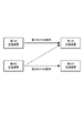
- FIG. 1 is a diagram illustrating a configuration example of a wireless communication system according to the present embodiment.
- the wireless communication system of FIG. 1 includes, for example, two transmission devices and two reception devices. This is only an example, and there may be three or more transmission devices and only one reception device.
- a first transmitter transmits a first orthogonal frequency division multiplexing (OFDM) signal using a cyclic prefix (CP), and a second transmitter transmits a second OFDM signal that does not use a CP. Shall be sent.
- the first receiving apparatus is a receiving apparatus that is the destination of the first OFDM signal, and receives the first OFDM signal and the second OFDM signal at the same time.
- OFDM orthogonal frequency division multiplexing
- CP cyclic prefix
- the first receiving apparatus is a receiving apparatus that is the destination of the first OFDM signal, and receives the first OFDM signal and the second OFDM signal at the same time.
- the second receiving apparatus is a receiving apparatus that is the destination of the second OFDM signal. Although omitted in FIG. 1, the second receiving apparatus can receive the first OFDM signal together with the second OFDM signal.
- one of the transmitting device and the receiving device may be a base station device and the other may be a mobile unit or a fixed terminal device, but both may be terminal devices, and the present invention is not limited to these examples.
- the OFDM signal here refers to all signals using carriers orthogonal to each other, and is a concept including DFT-S-OFDM (DFT spread OFDM) and the like.
- the wireless communication system of FIG. 1 is a time synchronization system, but is not limited thereto.
- the second transmission apparatus can control the second OFDM signal according to the information regarding the timing of the window for removing the CP of the first OFDM signal in the first reception apparatus
- Asynchronous systems can be used.
- the window for removing the CP refers to a time interval in which the receiving apparatus extracts a component in the time domain to be subjected to Fourier transform.
- the first OFDM signal and the second OFDM signal can be transmitted simultaneously by frequency division multiplexing in one of frequency bands such as an 800 MHz band, a 2 GHz band, and a 3 to 4 GHz band, for example.
- the receiving device collectively receives signals in the same frequency band.
- the first receiving apparatus since the first receiving apparatus is an apparatus that receives the first OFDM signal, the first receiving apparatus removes the CP by removing the CP in each of one or more symbols included in the first OFDM signal. A discrete Fourier transform (DFT) is performed on the later symbols.
- DFT discrete Fourier transform
- the first receiving apparatus may simultaneously receive the second OFDM signal in the same frequency band.
- CP removal which is processing in the time domain, is also executed for the second OFDM signal. It becomes. That is, the second OFDM signal is subjected to DFT after the signal component in the section corresponding to the CP of the first OFDM signal is removed.
- the orthogonality originally secured is lost, and the frequency component of the second OFDM signal leaks into the adjacent frequency band. It may interfere with the first OFDM signal that has been separated on the axis.
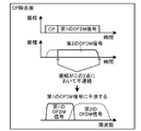
- FIGS. 2A and 2B This is due to the discontinuity of the component of the second OFDM signal at the start timing and end timing of the window.
- FIGS. 2A and 2B This state is schematically shown in FIGS. 2A and 2B.
- the first OFDM signal and the second OFDM signal are transmitted in the radio section without frequency components overlapping each other by frequency division multiplexing.
- the second OFDM signal does not interfere with the first OFDM signal in the radio section.
- the amplitude at the start timing and end timing of the symbols of the second OFDM signal is continuous.
- FIG. 2B when the first OFDM signal receiving apparatus removes the CP, the time interval component corresponding to the CP of the second OFDM signal is simultaneously removed.
- the amplitude of the second OFDM signal becomes discontinuous, the frequency component of the second OFDM signal spreads, and interferes with the first OFDM signal.
- the second transmission apparatus in order to prevent such interference, the second transmission apparatus generates the second OFDM signal so as to suppress the above-described discontinuity.
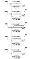
- the second OFDM signal is obtained by band-limiting the OFDM signal with a predetermined filter, and has the same time length as the first OFDM signal. Then, it is assumed that the first OFDM signal and the second OFDM signal are transmitted in synchronization. At this time, if the end timing of the window used for CP removal in the reception processing of the first OFDM signal is the boundary between two symbols of the main wave of the first OFDM signal, The amplitude of the main wave of the second OFDM signal is (almost) zero. Therefore, in this case, as indicated by 301 in FIG.
- the second transmission device sets the amplitude of the second OFDM signal at the start timing of the window in the reception process at the first reception device to a sufficiently small predetermined value. Make the following (almost zero). Thereby, even if some signal components are removed by CP removal of the first OFDM signal, continuity of the signal is ensured in the second OFDM signal, and as a result, the frequency of the second OFDM signal is increased. The amount of components leaking into adjacent frequency bands is reduced.
- the reception amplitude of the second OFDM signal in the first receiving device may not be (nearly) zero at the above-described window end timing.
- the second transmission apparatus is configured so that the reception amplitude of the second OFDM signal in the first reception apparatus is not more than a predetermined value that is sufficiently small at the window end timing. Signal generation may be performed.
- the second transmission apparatus can generate the second OFDM signal so that the reception amplitude at the first reception apparatus is equal to or less than a predetermined value only at the start timing or end timing of the window described above.
- the second transmitting apparatus is the first receiving apparatus in the interval after the period of the symbol preceding the symbol before the start timing of the window related to the symbol.
- the second OFDM signal may be generated so that the reception amplitude is a predetermined value or less.
- the second transmitting apparatus is the first receiving apparatus in the section before the symbol period after the symbol after the end timing of the window for the certain symbol.
- the second OFDM signal may be generated so that the reception amplitude is a predetermined value or less.
- FIG. 4 shows a hardware configuration example of the second transmission device described above.
- the second transmission device is referred to as a transmission device when there is no particular limitation.
- the transmission device has a hardware configuration as shown in FIG. 4, and includes, for example, a CPU 401, a ROM 402, a RAM 403, an external storage device 404, and a communication device 405.
- the CPU 401 executes a program that realizes each function of the second transmission device described above, which is recorded in any of the ROM 402, the RAM 403, and the external storage device 404.
- the CPU 401 is an example of a processor, and may be replaced by another processor such as an ASIC (application-specific integrated circuit), or may be replaced by a reconfigurable processor such as an FPGA (field programmable gate array). Also good.
- ASIC application-specific integrated circuit
- FPGA field programmable gate array
- a transmission apparatus controls the communication apparatus 405 by CPU401, for example, and communicates with another apparatus.
- the communication device 405 can transmit at least an OFDM signal that does not use a CP, and can also receive a signal.
- the communication device 405 transmits an OFDM signal using a CP or a signal of another wireless communication method. And may be configured to receive.
- the communication device 405 may be capable of transmitting signals in a plurality of frequency bands as well as in one frequency band. For example, both a cellular communication method and a wireless LAN communication method may be used. .
- the communication device 405 may be configured to perform wired communication.
- the transmission apparatus is schematically illustrated as having one communication apparatus 405, but is not limited thereto.
- the transmission device may include a first communication device for cellular communication and a second communication device for wireless LAN communication. Further, the transmission device may have separate communication devices for wired communication and wireless communication.
- the transmission apparatus may include dedicated hardware for executing each function, or may execute other parts with a computer that executes a part of the hardware and operates the program. Further, all functions of the transmission device may be executed by a computer and a program.
- FIG. 5 is a diagram illustrating a functional configuration example of the transmission apparatus according to the present embodiment.
- the transmission apparatus includes a transmission unit 501, a reception unit 502, a timing acquisition unit 503, and a signal generation unit 504.
- the transmission device may have functions (not shown) such as various functions of information processing equipment including the transmission device, for example, and has at least a function of either a base station device or a terminal device in cellular communication. Shall.
- the transmission unit 501 transmits the above-described second OFDM signal generated by the signal generation unit 504 described later.
- the transmission unit 501 includes, for example, an antenna and a circuit used for outputting a radio signal via the antenna.
- the receiving unit 502 receives a radio signal transmitted from another device.
- the receiving unit 502 includes, for example, an antenna and a circuit for processing a radio signal received via the antenna and extracting data. Note that the transmission unit 501 and the reception unit 502 can share one or more antennas and circuits.
- the timing acquisition unit 503 acquires information on at least one of the start timing and the end timing of the window used when removing the CP in the first OFDM signal receiving apparatus.
- the downlink signal can be transmitted synchronously between the base stations, so that the end timing of the CP portion when the terminal itself transmits the first OFDM signal is It can be specified as the start timing.
- the transmission apparatus can specify the symbol boundary as the window end timing.
- the timing of this window can be specified regardless of whether or not the transmission apparatus actually transmits the first OFDM signal.
- the transmission apparatus can estimate the timing of the above-described window related to the first OFDM signal based on, for example, a timing advance signal received from the base station apparatus.
- the transmitting apparatus may assume that the second OFDM signal transmitted by itself is received by the base station apparatus in synchronization with the first OFDM signal transmitted by another apparatus by the timing advance signal. it can. For this reason, the transmitting apparatus assumes that one or more symbols of the second OFDM signal transmitted by itself are received at the same timing as the symbols of the first OFDM signal, and ends the CP of the first OFDM signal.
- the timing may be estimated as the window start timing.
- the transmission apparatus may estimate the symbol boundary of the first OFDM signal as the window end timing.
- the transmitting device acquires information specifying the window timing directly or indirectly from the receiving device that is the partner device of its own communication. Also good. Further, for example, the second transmission device may acquire information related to window timing from the first transmission device.
- the signal generation unit 504 generates a second OFDM signal based on the information about the window timing in the first OFDM signal receiving apparatus acquired by the timing acquisition unit 503. Specifically, as described above, the signal generation unit 504 has a predetermined reception amplitude of the second OFDM signal in the first OFDM signal receiving apparatus at at least one of the start timing and the end timing of the window. A second OFDM signal is generated so as to be less than or equal to the value. Note that the signal generation unit 504 may set the above-described reception amplitude to be equal to or less than a predetermined value in a section before the start timing of the window and after the end timing of the previous symbol section.
- the signal generation unit 504 may make the above-described reception amplitude equal to or less than a predetermined value in a section after the start timing of the window and after the start timing of the subsequent symbol section. Further, the signal generation unit 504 includes the first and second reception amplitudes so as to be equal to or less than a predetermined value in a predetermined length section determined based on a delay profile, for example, including at least one of a window start timing and an end timing. Two OFDM signals may be generated.
- the signal generation unit 504 generates a temporary modulation symbol.
- the signal generation unit 504 obtains a temporary modulation symbol by mapping a bit string to be transmitted to a point on the IQ plane by a modulation scheme such as QPSK, 16QAM, or 64QAM.
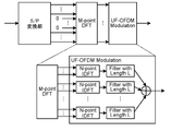
- the temporary modulation symbol corresponds to a time-domain signal, and is input to a serial / parallel converter (S / P converter) and parallelized, and then input to an M-point DFT (discrete Fourier transformer).
- S / P converter serial / parallel converter
- M-point DFT discrete Fourier transformer
- the signal generation unit 504 generates the reception amplitude when the first OFDM signal receiving apparatus receives the second OFDM signal at a certain timing so that the reception amplitude is a predetermined value or less. . For this reason, the signal generation unit 504 inserts “0” as a transmission symbol corresponding to the certain timing. Therefore, the signal generation unit 504 generates Mh temporary modulation symbols when, for example, h “0” s are inserted.
- the temporary modulation symbols that are parallelized with “0” inserted in part are converted into frequency domain signals composed of M samples by M-point DFT.
- the signal converted into the frequency domain signal is input to the UF-OFDM modulator.
- the input frequency domain signal is distributed and input to a plurality of N-point IDFTs (Inverse Discrete Fourier Transformers).
- IDFT a frequency domain signal is converted into a time domain signal and output.
- a plurality of IDFTs correspond to mutually different subbands. For example, when there are B IDFTs, M samples are input to each IDFT, for example, M / B and distributed to B subbands. To be sent.
- each IDFT is band-limited by a filter of length L and then added and transmitted.
- the filter can generate an OFDM signal that does not use the CP and has the same time length as the OFDM signal that uses the CP. Since M ⁇ N, not only the output of the M point DFT described above but also a sample related to “0” or another signal is input to at least a part of the N point IDFT.
- the signal output by the M-point DFT is over-sampled N / M times by passing through the N-point IDFT.
- the i-th sample input to the M-point DFT is the i ⁇ N / M-th sample in the output of the IDFT. From this, for example, by setting the k ⁇ M / N-th sample among the inputs in the M-point DFT to 0, the amplitude of the k-th sample of the output of the N-point IDFT can be reduced to a predetermined value or less.
- the sample output by the IDFT is a time-domain signal transmitted as a radio signal after being band-limited by a filter.
- the signal generation unit 504 considers the influence of the filter so that the amplitude is sufficiently small at the timing based on the information acquired by the timing acquisition unit 503 described above.
- the position where “0” is inserted is adjusted. For example, when the amplitude of the p-th sample of the final signal is reduced and the filter is delayed by L samples, the (p ⁇ L) ⁇ M / N-th sample among the inputs in the M-point DFT is 0.
- the signal generation unit 504 has the reception amplitude of the second OFDM signal at or below the predetermined value at the start timing / end timing of the window used when removing the CP.
- a second OFDM signal can be generated.
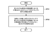
- the transmission apparatus acquires information regarding the timing of the window used for CP removal of the first OFDM signal in the reception apparatus for the first OFDM signal (S701). ).
- the transmission device can acquire information related to the timing of the window actually used by the reception device of the first OFDM signal by receiving a notification from the reception device.
- the transmission apparatus may estimate the window timing in the reception apparatus based on, for example, a timing advance signal.
- the transmitting apparatus can know the timing of the CP of the first OFDM signal when the symbol of the first OFDM signal and the symbol of the second OFDM signal are synchronized, The window timing may be estimated from the timing.
- the transmission apparatus is configured so that the reception amplitude of the first OFDM signal at the reception apparatus at the start timing and the end timing of the window specified based on the acquired information is equal to or less than a predetermined value.
- a second OFDM signal is generated (S702). For example, as shown in 301 to 304 in FIG. 3, the transmission apparatus can perform the first operation in an arbitrary form so as to reduce the discontinuity generated in the amplitude of the second OFDM signal at the start timing and the end timing of the window. Two OFDM signals may be generated.
- the transmission apparatus prevents the second OFDM signal from interfering with the first OFDM signal in the reception / demodulation process of the first OFDM signal, or the amount of interference. Can be made sufficiently small. Therefore, it is possible to suppress degradation in quality and frequency utilization efficiency when the first OFDM signal having CP and the second OFDM signal not having CP are simultaneously transmitted by frequency division multiplexing.
Landscapes
- Engineering & Computer Science (AREA)
- Computer Networks & Wireless Communication (AREA)
- Signal Processing (AREA)
- Mobile Radio Communication Systems (AREA)
Abstract
他の装置によってサイクリックプリフィックスを用いる第1のOFDM信号が送信されている間に、サイクリックプリフィックスを用いない第2のOFDM信号を送信することができる通信装置は、第1のOFDM信号の受信装置において、その第1のOFDM信号からサイクリックプリフィックスを除去する際に用いるウィンドウのタイミングに関する情報を取得し、ウィンドウが開始される第1のタイミングにおいて第2のOFDM信号の受信装置における振幅が所定値以下となるように、第2のOFDM信号の1つ以上の送信シンボルを生成し、生成された1つ以上の送信シンボルを含む第2のOFDM信号を送信する。
Description
本発明は、通信装置、制御方法及びプログラムに関するものであり、具体的には、無線通信システムにおける干渉制御技術に関する。
現在、次世代の移動体無線通信方式として、サイクリックプリフィックスを用いない直交周波数分割多重(OFDM)信号を利用する通信方式が提案されている(非特許文献1)。一方、導入の開始時点においては、次世代の通信方式の信号が、サイクリックプリフィックスを用いるOFDM信号を利用する現世代の通信方式の信号と、同一周波数帯域の異なる周波数チャネルで送信されることが想定される。また、次世代の通信方式の信号として、サイクリックプリフィックスを用いるOFDM信号とサイクリックプリフィックスを用いないOFDM信号とが同一周波数帯で共存することも想定されうる。
Thorsten.W等、「ユニバーサルフィルタード(UF-)OFDMに基づく5Gエアインタフェースデザイン(5G Air Interface Design based on Universal Filtered (UF-)OFDM)」、International Conference on Digital Signal Processing、2014年8月
受信装置は、同じ時間区間において受信された同一周波数帯に含まれる複数のOFDM信号の復調処理を同時に実行する。このとき、受信装置においては、サイクリックプリフィックスを用いる第1のOFDM信号とサイクリックプリフィックスを用いない第2のOFDM信号とが、同時に受信される場合がありうる。ここで、受信装置は、第1のOFDM信号の復調をするものとする。この場合、受信装置は、第1のOFDM信号からサイクリックプリフィックスを除去して離散フーリエ変換を施す受信処理を実行する。一方、受信装置は、第1のOFDM信号と同時に第2のOFDM信号をも受信しており、第1のOFDM信号の受信処理と同時に、第2のOFDM信号に対しても第1のOFDM信号に対する受信処理を実行することとなる。このとき、第2のOFDM信号から、第1のOFDM信号のサイクリックプリフィックスの時間区間の成分を除去すると、サイクリックプリフィックス除去後の第2のOFDM信号が直交性を失い、結果として第1のOFDM信号に干渉してしまいうる。
本発明は、サイクリックプリフィックスを用いるOFDM信号に干渉を与えないような、サイクリックプリフィックスを用いないOFDM信号を生成する。
本発明の一態様に係る通信装置は、他の装置によってサイクリックプリフィックスを用いる第1の直交周波数分割多重(OFDM)信号が送信されている間に、サイクリックプリフィックスを用いない第2のOFDM信号を送信することができる通信装置であって、前記第1のOFDM信号の受信装置において、当該第1のOFDM信号から前記サイクリックプリフィックスを除去する際に用いるウィンドウのタイミングに関する情報を取得する取得手段と、前記ウィンドウが開始される第1のタイミングにおいて前記第2のOFDM信号の前記受信装置における振幅が所定値以下となるように、前記第2のOFDM信号の1つ以上の送信シンボルを生成する生成手段と、前記生成手段によって生成された前記1つ以上の送信シンボルを含む前記第2のOFDM信号を送信する送信手段と、を有する。
本発明によれば、サイクリックプリフィックスを用いるOFDM信号に干渉を与えないような、サイクリックプリフィックスを用いないOFDM信号を生成することができる。
本発明のその他の特徴及び利点は、添付図面を参照とした以下の説明により明らかになるであろう。なお、添付図面においては、同じ若しくは同様の構成には、同じ参照番号を付す。
添付図面は明細書に含まれ、その一部を構成し、本発明の実施の形態を示し、その記述と共に本発明の原理を説明するために用いられる。
無線通信システムの構成例を示す図。
サイクリックプリフィックスを用いるOFDM信号とサイクリックプリフィックスを用いないOFDM信号とが受信される際の課題を説明する図。
サイクリックプリフィックスを用いるOFDM信号とサイクリックプリフィックスを用いないOFDM信号とが受信される際の課題を説明する図。
送信装置におけるサイクリックプリフィックスを用いないOFDM信号の生成方法の概念を示す図。
送信装置のハードウェア構成例を示す図。
送信装置の機能構成例を示すブロック図。
信号生成部の構成例を示すブロック図。
送信装置が実行する処理の流れの例を示す図。
以下、本発明の実施の形態について、図面を参照しながら説明する。
(無線通信システムの構成)
図1は、本実施形態に係る無線通信システムの構成例を示す図である。図1の無線通信システムは、一例として、2つの送信装置と、2つの受信装置を含んでいる。なお、これは一例であり、送信装置及び受信装置は3つ以上又は1つのみ存在してもよい。図1において、第1の送信装置は、サイクリックプリフィックス(CP)を用いる第1の直交周波数分割多重(OFDM)信号を送信し、第2の送信装置は、CPを用いない第2のOFDM信号を送信するものとする。また、第1の受信装置は、第1のOFDM信号の宛先の受信装置であり、第1のOFDM信号と第2のOFDM信号とを同時に受信するものとする。第2の受信装置は、第2のOFDM信号の宛先の受信装置である。なお、図1では省略しているが、第2の受信装置は、第2のOFDM信号とともに第1のOFDM信号を受信しうる。送信装置及び受信装置は、例えば、一方が基地局装置であり、他方が移動体又は固定の端末装置でありうるが、両方が端末装置であってもよく、これらの例に限られない。
図1は、本実施形態に係る無線通信システムの構成例を示す図である。図1の無線通信システムは、一例として、2つの送信装置と、2つの受信装置を含んでいる。なお、これは一例であり、送信装置及び受信装置は3つ以上又は1つのみ存在してもよい。図1において、第1の送信装置は、サイクリックプリフィックス(CP)を用いる第1の直交周波数分割多重(OFDM)信号を送信し、第2の送信装置は、CPを用いない第2のOFDM信号を送信するものとする。また、第1の受信装置は、第1のOFDM信号の宛先の受信装置であり、第1のOFDM信号と第2のOFDM信号とを同時に受信するものとする。第2の受信装置は、第2のOFDM信号の宛先の受信装置である。なお、図1では省略しているが、第2の受信装置は、第2のOFDM信号とともに第1のOFDM信号を受信しうる。送信装置及び受信装置は、例えば、一方が基地局装置であり、他方が移動体又は固定の端末装置でありうるが、両方が端末装置であってもよく、これらの例に限られない。
なお、ここでのOFDM信号とは、互いに直交するキャリアを用いた信号全般を指し、DFT-S-OFDM(DFTスプレッドOFDM)等をも含む概念である。
また、以下の説明では、図1の無線通信システムが時間同期システムであるものとするが、これに限られない。例えば、第2の送信装置が、第1の受信装置において第1のOFDM信号のCPを除去するためのウィンドウのタイミングに関する情報に応じて、第2のOFDM信号を制御することができる前提において、非同期システムが用いられうる。ここで、CPを除去するためのウィンドウとは、受信装置がフーリエ変換の対象とする時間領域の成分を抽出する時間区間のことを指す。
第1のOFDM信号と第2のOFDM信号は、例えば、800MHz帯、2GHz帯、3~4GHz帯等の周波数帯のうちの1つにおいて、周波数分割多重によって同時に送信されうる。受信装置は、同一周波数帯の信号を一括して受信処理する。例えば、第1の受信装置は、自身が第1のOFDM信号を受信する装置であるため、第1のOFDM信号に含まれる1つ以上のシンボルのそれぞれにおいて、CPを除去して、CPの除去後のシンボルに対して離散フーリエ変換(DFT)を実行する。
このとき、第1の受信装置は、同一の周波数帯で、第2のOFDM信号を同時に受信する場合がある。この場合、第2のOFDM信号は、時間領域において第1のOFDM信号と重畳して受信されるため、時間領域における処理であるCP除去は、第2のOFDM信号に対しても実行されることとなる。すなわち、第2のOFDM信号は、第1のOFDM信号のCPに対応する区間の信号成分が除去されて、DFTを施されることとなる。ここで、第2のOFDM信号に対してそのような信号成分の除去を行うと、本来担保されていた直交性が崩れ、第2のOFDM信号の周波数成分が隣接する周波数帯域に漏れ込み、周波数軸上で分離されていた第1のOFDM信号に干渉してしまいうる。これは、上述のウィンドウの開始タイミングと終了タイミングとにおける第2のOFDM信号の成分が不連続となることに起因する。この状態を、概略的に図2A及び図2Bに示す。図2Aに示すように、第1のOFDM信号および第2のOFDM信号は、無線区間において、周波数分割多重によって、周波数成分が互いに重なることなく送信される。このため、第2のOFDM信号は、無線区間において第1のOFDM信号に干渉することはない。これは、第2のOFDM信号のシンボルの開始タイミングと終了タイミングにおける振幅が連続しているからである。これに対して、図2Bに示すように、第1のOFDM信号の受信装置が、CPを除去すると、同時に第2のOFDM信号のそのCPに対応する時間区間の成分が除去される。この結果、第2のOFDM信号の振幅が不連続となり、第2のOFDM信号の周波数成分が拡散し、第1のOFDM信号に対して干渉を与えることとなってしまう。
本実施形態では、このような干渉を防ぐために、第2の送信装置が、上述の不連続性を抑えるようにして第2のOFDM信号を生成するようにする。ここで、第2のOFDM信号は、OFDM信号を所定のフィルタによって帯域制限して得られたものとし、第1のOFDM信号と同じ時間長を有するものとする。そして、第1のOFDM信号と第2のOFDM信号とが同期して送信されるものとする。このとき、第1のOFDM信号の受信処理でCP除去の際に用いられるウィンドウの終了タイミングが、第1のOFDM信号の主波の2つのシンボルの間の境界であるものとすると、そのタイミングにおいて第2のOFDM信号の主波の振幅は(ほぼ)ゼロとなる。したがって、この場合、図3の301に示すように、第2の送信装置は、第1の受信装置での受信処理におけるウィンドウの開始タイミングにおける第2のOFDM信号の振幅を、十分に小さい所定値以下(ほぼゼロ)となるようにする。これにより、第2のOFDM信号は、第1のOFDM信号のCP除去によって、一部の信号成分が除去されたとしても、信号の連続性が担保され、結果として、第2のOFDM信号の周波数成分が隣接する周波数帯域に漏れ込む量が低減される。
また、例えば非同期システムにおいては、上述のウィンドウの終了タイミングにおいて、第2のOFDM信号の第1の受信装置における受信振幅が(ほぼ)ゼロでない場合がありうる。このため、第2の送信装置は、図3の302に示すように、ウィンドウの終了タイミングにおいて、第2のOFDM信号の第1の受信装置における受信振幅が十分に小さい所定値以下となるように、信号生成を行ってもよい。
なお、第2の送信装置は、上述のウィンドウの開始タイミング又は終了タイミングのみにおいて第1の受信装置での受信振幅が所定値以下となるように第2のOFDM信号を生成しうるが、これに限られない。例えば、第2の送信装置は、図3の303に示すように、あるシンボルに関するウィンドウの開始タイミングより前で、そのシンボルの前のシンボルの期間の後の区間で、第1の受信装置での受信振幅が所定値以下となるように第2のOFDM信号を生成してもよい。また、第2の送信装置は、図3の304に示すように、あるシンボルに関するウィンドウの終了タイミングより後で、そのシンボルの後のシンボルの期間の前の区間で、第1の受信装置での受信振幅が所定値以下となるように第2のOFDM信号を生成してもよい。
以上のようにすることで、第1のOFDM信号に関するCPを除去したことに伴って、第2のOFDM信号の一部が除去されたとしても、直交性の崩れを抑え、第2のOFDM信号からの第1のOFDM信号への干渉を抑制することができる。以下では、このような第2の送信装置の構成と処理の流れについて詳細に説明する。
(ハードウェア構成)
図4に、上述の第2の送信装置のハードウェア構成例を示す。なお、以下では、第2の送信装置のことを、特に限定する必要がない場合には送信装置と呼ぶ。送信装置は、一例において、図4に示すようなハードウェア構成を有し、例えば、CPU401、ROM402、RAM403、外部記憶装置404、及び通信装置405を有する。送信装置では、例えばROM402、RAM403及び外部記憶装置404のいずれかに記録された、上述のような第2の送信装置の各機能を実現するプログラムがCPU401により実行される。ここで、CPU401はプロセッサの例であり、ASIC(特定用途向け集積回路)等の他のプロセッサによって置き換えられてもよいし、FPGA(フィールドプログラマブルゲートアレイ)等の再構成可能なプロセッサによって置き換えられてもよい。
図4に、上述の第2の送信装置のハードウェア構成例を示す。なお、以下では、第2の送信装置のことを、特に限定する必要がない場合には送信装置と呼ぶ。送信装置は、一例において、図4に示すようなハードウェア構成を有し、例えば、CPU401、ROM402、RAM403、外部記憶装置404、及び通信装置405を有する。送信装置では、例えばROM402、RAM403及び外部記憶装置404のいずれかに記録された、上述のような第2の送信装置の各機能を実現するプログラムがCPU401により実行される。ここで、CPU401はプロセッサの例であり、ASIC(特定用途向け集積回路)等の他のプロセッサによって置き換えられてもよいし、FPGA(フィールドプログラマブルゲートアレイ)等の再構成可能なプロセッサによって置き換えられてもよい。
そして、送信装置は、例えばCPU401により通信装置405を制御して、他の装置と通信を行う。なお、通信装置405は、少なくともCPを用いないOFDM信号を送信することができるほか、信号の受信を行うこともでき、場合によってはCPを用いるOFDM信号や、他の無線通信方式の信号を送信および受信できるように構成されてもよい。また、通信装置405は、1つの周波数帯のみならず、複数の周波数帯において信号を送信できてもよく、例えばセルラの通信方式と無線LANの通信方式との両者を利用可能であってもよい。さらに、通信装置405は、有線通信を行うことができるように構成されてもよい。なお、図4の構成において、送信装置は、1つの通信装置405を有するような概略図を示しているが、これに限られない。例えば、送信装置は、セルラ通信用の第1の通信装置と無線LAN通信用の第2の通信装置とを有しうる。また、送信装置は、有線通信用と無線通信用とで、別個の通信装置を有しうる。
なお、送信装置は、各機能を実行する専用のハードウェアを備えてもよいし、一部をハードウェアで実行し、プログラムを動作させるコンピュータでその他の部分を実行してもよい。また、送信装置の全機能がコンピュータとプログラムにより実行されてもよい。
(機能構成)
図5は、本実施形態に係る送信装置の機能構成例を示す図である。送信装置は、一例において、送信部501、受信部502、タイミング取得部503、および信号生成部504を有する。なお、送信装置は、例えば送信装置を含む情報処理機器が有する様々な機能等の不図示の機能を有してもよく、少なくとも、セルラ通信における基地局装置または端末装置のいずれかの機能を有するものとする。
図5は、本実施形態に係る送信装置の機能構成例を示す図である。送信装置は、一例において、送信部501、受信部502、タイミング取得部503、および信号生成部504を有する。なお、送信装置は、例えば送信装置を含む情報処理機器が有する様々な機能等の不図示の機能を有してもよく、少なくとも、セルラ通信における基地局装置または端末装置のいずれかの機能を有するものとする。
送信部501は後述の信号生成部504が生成した上述の第2のOFDM信号を送信する。送信部501は、例えば、アンテナとそのアンテナを介して無線信号を出力するために用いられる回路とを含んで構成される。受信部502は、他の装置が送信した無線信号を受信する。受信部502は、例えば、アンテナと、そのアンテナを介して受信した無線信号を処理してデータを取り出すための回路とを含んで構成される。なお、送信部501と受信部502は、1つ以上のアンテナと回路とを共有しうる。
タイミング取得部503は、上述の第1のOFDM信号の受信装置において、CPを除去する際に用いるウィンドウの開始タイミングと終了タイミングとの少なくともいずれかに関する情報を取得する。
例えば、送信装置が基地局装置である場合、下り信号を基地局間で同期して送信することができるため、自身が第1のOFDM信号を送信した場合の、CP部分の終了タイミングを、ウィンドウの開始タイミングとして特定することができる。また、同様にして、送信装置は、シンボルの境界を、ウィンドウの終了タイミングとして特定することができる。送信装置は、自身が基地局装置である場合、このウィンドウのタイミングの特定を、送信装置が実際に第1のOFDM信号を送信すると否とによらず行うことができる。
一方、送信装置は、自身が端末装置である場合、例えば基地局装置から受信したタイミングアドバンス信号等に基づいて、第1のOFDM信号に関する上述のウィンドウのタイミングを推定することができる。この場合、送信装置は、タイミングアドバンス信号によって、自身が送信する第2のOFDM信号が、他の装置が送信する第1のOFDM信号と基地局装置において同期して受信されると想定することができる。このため、送信装置は、自身が送信する第2のOFDM信号の1つ以上のシンボルが、第1のOFDM信号のシンボルと同じタイミングで受信されるものとして、第1のOFDM信号のCPの終了タイミングをウィンドウの開始タイミングとして推定しうる。同様に、送信装置は、第1のOFDM信号のシンボルの境界をウィンドウの終了タイミングとして推定しうる。
なお、送信装置は、自身が基地局装置であっても端末装置であっても、ウィンドウのタイミングを直接または間接的に指定する情報を、自身の通信の相手装置である受信装置から取得してもよい。また、例えば、第2の送信装置は、第1の送信装置からウィンドウのタイミングに関する情報を取得してもよい。
信号生成部504は、タイミング取得部503において取得した、第1のOFDM信号の受信装置におけるウィンドウのタイミングに関する情報に基づいて、第2のOFDM信号を生成する。具体的には、信号生成部504は、上述のように、ウィンドウの開始タイミングと終了タイミングとの少なくともいずれかでの、第1のOFDM信号の受信装置における第2のOFDM信号の受信振幅が所定値以下となるように、第2のOFDM信号を生成する。なお、信号生成部504は、ウィンドウの開始タイミングより前で、前のシンボル区間の終了タイミングより後の区間においても、上述の受信振幅が所定値以下となるようにしてもよい。また、信号生成部504は、ウィンドウの開始タイミングより後で、後のシンボル区間の開始タイミングより後の区間においても、上述の受信振幅が所定値以下となるようにしてもよい。さらに、信号生成部504は、ウィンドウの開始タイミングと終了タイミングとの少なくともいずれかを含む、例えば遅延プロファイルに基づいて定められる所定長の区間において、上述の受信振幅が所定値以下となるように第2のOFDM信号を生成してもよい。
Universal Filtered(UF)-OFDMが用いられた場合の、信号生成部504の構成について図6を用いて説明する。まず、信号生成部504は、一時変調シンボルを生成する。信号生成部504は、例えば、送信対象のビット列を、QPSK、16QAM、64QAM等の変調方式によってIQ平面上の点へマッピングすることによって、一時変調シンボルを得る。なお、一時変調シンボルは、時間領域の信号に相当し、シリアル/パラレル変換器(S/P変換器)へ入力されて並列化された後に、MポイントDFT(離散フーリエ変換器)へと入力される。このとき、上述のように、信号生成部504は、一定のタイミングにおいて、第1のOFDM信号の受信装置が第2のOFDM信号を受信した場合の受信振幅が所定値以下となるように生成する。このため、信号生成部504は、その一定のタイミングに対応する送信シンボルとして「0」を挿入する。このため、信号生成部504は、例えばh個の「0」を挿入する場合には、M-h個の一時変調シンボルを生成する。
その後、一部において「0」が挿入されて並列化された一時変調シンボルは、MポイントDFTによって、M個のサンプルからなる周波数領域の信号に変換される。そして、周波数領域の信号に変換された信号は、UF-OFDM変調器へと入力される。ここで、UF-OFDM変調器では、入力された周波数領域の信号を、複数のNポイントIDFT(逆離散フーリエ変換器)に分散して入力する。IDFTでは、周波数領域の信号を時間領域の信号に変換して出力する。ここで、複数のIDFTは互いに異なるサブバンドに対応し、例えば、IDFTがB個存在する場合は、M個のサンプルは例えばM/B個ずつ各IDFTに入力され、B個のサブバンドに分散されて送信される。各IDFTの出力は、長さLのフィルタによって帯域制限された後に加算されて送信される。ここで、フィルタによって、CPを用いるOFDM信号と同じ時間長の、CPを用いないOFDM信号を生成することができる。なお、M<Nであるため、NポイントIDFTには、上述のMポイントDFTの出力のみならず、その少なくとも一部において「0」または他の信号に関するサンプルが入力される。
このとき、MポイントDFTによって出力された信号は、NポイントIDFTを経ることによって、N/M倍にオーバーサンプリングした状態となる。このため、例えば、MポイントDFTに入力されるi番目のサンプルは、IDFTの出力におけるi×N/M番目のサンプルとなる。このことから、例えば、MポイントDFTにおける入力のうち、k×M/N番目のサンプルを0とすることによって、NポイントIDFTの出力のk番目のサンプルの振幅を所定値以下とすることができる。IDFTが出力するサンプルは、フィルタによって帯域制限された後に無線信号として送信される時間領域の信号である。このため、信号生成部504は、フィルタ後の信号について、上述のタイミング取得部503が取得した情報に基づくタイミングで振幅が十分に小さくなるように、フィルタの影響も考慮して、MポイントDFTへの入力において「0」を挿入する位置を調整する。例えば、最終的な信号のpサンプル目の振幅を小さくする場合であって、フィルタによってLサンプルだけ遅延する場合、MポイントDFTにおける入力のうち、(p-L)×M/N番目のサンプルを0とする。
このように、信号生成部504は、第1のOFDM信号の受信装置における、CPを除去する際に用いるウィンドウの開始タイミング/終了タイミングでの第2のOFDM信号の受信振幅が所定値以下となるように、第2のOFDM信号を生成することができる。
(処理の流れ)
次に、送信装置が実行する処理の流れについて、図7を用いて説明する。送信装置は、まず、第2のOFDM信号を生成するのに先立って、第1のOFDM信号の受信装置における、第1のOFDM信号のCP除去に用いられるウィンドウのタイミングに関する情報を取得する(S701)。送信装置は、例えば、第1のOFDM信号の受信装置が実際に用いるウィンドウのタイミングに関する情報を、その受信装置からの通知を受けることによって取得しうる。また、送信装置は、例えば、タイミングアドバンス信号等に基づいて、受信装置におけるウィンドウのタイミングを推定してもよい。さらに、送信装置は、第1のOFDM信号のシンボルと第2のOFDM信号のシンボルとの間で同期がとれている場合には、第1のOFDM信号のCPのタイミングを知ることができるため、そのタイミングからウィンドウのタイミングを推定してもよい。
次に、送信装置が実行する処理の流れについて、図7を用いて説明する。送信装置は、まず、第2のOFDM信号を生成するのに先立って、第1のOFDM信号の受信装置における、第1のOFDM信号のCP除去に用いられるウィンドウのタイミングに関する情報を取得する(S701)。送信装置は、例えば、第1のOFDM信号の受信装置が実際に用いるウィンドウのタイミングに関する情報を、その受信装置からの通知を受けることによって取得しうる。また、送信装置は、例えば、タイミングアドバンス信号等に基づいて、受信装置におけるウィンドウのタイミングを推定してもよい。さらに、送信装置は、第1のOFDM信号のシンボルと第2のOFDM信号のシンボルとの間で同期がとれている場合には、第1のOFDM信号のCPのタイミングを知ることができるため、そのタイミングからウィンドウのタイミングを推定してもよい。
その後、送信装置は、取得した情報に基づいて特定されたウィンドウの開始タイミングと終了タイミングとの少なくともいずれかでの、第1のOFDM信号の受信装置における受信振幅が所定値以下となるように、第2のOFDM信号を生成する(S702)。送信装置は、例えば、図3の301~304のように、ウィンドウの開始タイミングと終了タイミングとにおいて、第2のOFDM信号の振幅に生じる不連続性を低減するような、任意の形式で、第2のOFDM信号を生成しうる。
このようにして、本実施形態に係る送信装置は、第1のOFDM信号の受信/復調処理において、第2のOFDM信号が第1のOFDM信号へ干渉を与えないようにすること、または干渉量を十分に小さくすることができる。したがって、CPを有する第1のOFDM信号とCPを有しない第2のOFDM信号とが、周波数分割多重によって同時に送信されるときの品質劣化や周波数利用効率の劣化を抑えることができる。
本発明は上記実施の形態に制限されるものではなく、本発明の精神及び範囲から離脱することなく、様々な変更及び変形が可能である。従って、本発明の範囲を公にするために、以下の請求項を添付する。
本願は、2016年7月22日提出の日本国特許出願特願2016-144726を基礎として優先権を主張するものであり、その記載内容の全てを、ここに援用する。
Claims (9)
- 他の装置によってサイクリックプリフィックスを用いる第1の直交周波数分割多重(OFDM)信号が送信されている間に、サイクリックプリフィックスを用いない第2のOFDM信号を送信することができる通信装置であって、
前記第1のOFDM信号の受信装置において、当該第1のOFDM信号から前記サイクリックプリフィックスを除去する際に用いるウィンドウのタイミングに関する情報を取得する取得手段と、
前記ウィンドウが開始される第1のタイミングにおいて前記第2のOFDM信号の前記受信装置における振幅が所定値以下となるように、前記第2のOFDM信号の1つ以上の送信シンボルを生成する生成手段と、
前記生成手段によって生成された前記1つ以上の送信シンボルを含む前記第2のOFDM信号を送信する送信手段と、
を有することを特徴とする通信装置。 - 前記生成手段は、前記第2のOFDM信号の1つのシンボルを、前記第1のタイミングの前で、かつ、当該シンボルの前のシンボルの期間の後においても、前記第2のOFDM信号の前記受信装置における振幅が所定値以下となるように、生成する、
ことを特徴とする請求項1に記載の通信装置。 - 前記生成手段は、前記第2のOFDM信号の1つのシンボルを、前記第1のタイミングの前で、かつ、当該シンボルの前のシンボルの期間の後においては、前記第2のOFDM信号の前記受信装置における振幅を制限することなく、生成する、
ことを特徴とする請求項1に記載の通信装置。 - 前記生成手段は、さらに前記ウィンドウが終了する第2のタイミングにおいて前記第2のOFDM信号の前記受信装置における振幅が所定値以下となるように、前記第2のOFDM信号の1つ以上の送信シンボルを生成する、
ことを特徴とする請求項1から3のいずれか1項に記載の通信装置。 - 前記生成手段は、前記第2のOFDM信号の1つのシンボルを、前記第2のタイミングの後で、かつ、当該シンボルの後のシンボルの期間の前においても、前記第2のOFDM信号の前記受信装置における振幅が所定値以下となるように、生成する、
ことを特徴とする請求項4に記載の通信装置。 - 前記生成手段は、前記第2のOFDM信号の1つのシンボルを、前記第2のタイミングの後で、かつ、当該シンボルの後のシンボルの期間の前においては、前記第2のOFDM信号の前記受信装置における振幅を制限することなく、生成する、
ことを特徴とする請求項4に記載の通信装置。 - 前記第1のOFDM信号と前記第2のOFDM信号とは、周波数分割多重により同時に送信される信号である、
ことを特徴とする請求項1から6のいずれか1項に記載の通信装置。 - 他の装置によってサイクリックプリフィックスを用いる第1の直交周波数分割多重(OFDM)信号が送信されている間に、サイクリックプリフィックスを用いない第2のOFDM信号を送信することができる通信装置の制御方法であって、
前記第1のOFDM信号の受信装置において、当該第1のOFDM信号から前記サイクリックプリフィックスを除去する際に用いるウィンドウのタイミングに関する情報を取得する取得工程と、
前記ウィンドウが開始される第1のタイミングにおいて前記第2のOFDM信号の前記受信装置における振幅が所定値以下となるように、前記第2のOFDM信号の1つ以上の送信シンボルを生成する生成工程と、
前記生成工程において生成された前記1つ以上の送信シンボルを含む前記第2のOFDM信号を送信する送信工程と、
を有することを特徴とする制御方法。 - 他の装置によってサイクリックプリフィックスを用いる第1の直交周波数分割多重(OFDM)信号が送信されている間に、サイクリックプリフィックスを用いない第2のOFDM信号を送信することができる通信装置に備えられたコンピュータに、
前記第1のOFDM信号の受信装置において、当該第1のOFDM信号から前記サイクリックプリフィックスを除去する際に用いるウィンドウのタイミングに関する情報を取得する取得工程と、
前記ウィンドウが開始される第1のタイミングにおいて前記第2のOFDM信号の前記受信装置における振幅が所定値以下となるように、前記第2のOFDM信号の1つ以上の送信シンボルを生成する生成工程と、
前記生成工程において生成された前記1つ以上の送信シンボルを含む前記第2のOFDM信号を送信する送信工程と、
を実行させるためのプログラム。
Applications Claiming Priority (2)
| Application Number | Priority Date | Filing Date | Title |
|---|---|---|---|
| JP2016144726A JP2018014687A (ja) | 2016-07-22 | 2016-07-22 | 通信装置、制御方法及びプログラム |
| JP2016-144726 | 2016-07-22 |
Publications (1)
| Publication Number | Publication Date |
|---|---|
| WO2018016121A1 true WO2018016121A1 (ja) | 2018-01-25 |
Family
ID=60992216
Family Applications (1)
| Application Number | Title | Priority Date | Filing Date |
|---|---|---|---|
| PCT/JP2017/009935 Ceased WO2018016121A1 (ja) | 2016-07-22 | 2017-03-13 | 通信装置、制御方法及びプログラム |
Country Status (2)
| Country | Link |
|---|---|
| JP (1) | JP2018014687A (ja) |
| WO (1) | WO2018016121A1 (ja) |
Citations (1)
| Publication number | Priority date | Publication date | Assignee | Title |
|---|---|---|---|---|
| EP3139557A1 (en) * | 2015-09-03 | 2017-03-08 | Alcatel Lucent | Method and apparatus for reducing interference between ofdm and universal filtered multi-carrier (ufmc) signals |
-
2016
- 2016-07-22 JP JP2016144726A patent/JP2018014687A/ja active Pending
-
2017
- 2017-03-13 WO PCT/JP2017/009935 patent/WO2018016121A1/ja not_active Ceased
Patent Citations (1)
| Publication number | Priority date | Publication date | Assignee | Title |
|---|---|---|---|---|
| EP3139557A1 (en) * | 2015-09-03 | 2017-03-08 | Alcatel Lucent | Method and apparatus for reducing interference between ofdm and universal filtered multi-carrier (ufmc) signals |
Non-Patent Citations (1)
| Title |
|---|
| NOKIA ET AL.: "Initial uplink performance results for New Radio waveforms below 6 GHz", 3GPP TSG-RAN WG1#85 RL-165013, 23 May 2016 (2016-05-23), Retrieved from the Internet <URL:http://www.3gpp.org/ftp/tsg_ran/WGl_RL1/TSGR1_1122/Docs/R1-165013.zip> * |
Also Published As
| Publication number | Publication date |
|---|---|
| JP2018014687A (ja) | 2018-01-25 |
Similar Documents
| Publication | Publication Date | Title |
|---|---|---|
| US10826745B2 (en) | System and method for guard band utilization for synchronous and asynchronous communications | |
| CN114270977B (zh) | 下行链路控制信息的发送和接收 | |
| US11888664B2 (en) | Symbol-synchronous continuous fast-convolution-based processing | |
| CN108134624B (zh) | 一种参考信号发送、接收方法、发送端及接收端 | |
| CN103475613A (zh) | 一种信号发送和接收方法及相关设备 | |
| CN106961405A (zh) | 多载波系统的数据调制、解调方法、数据传输方法及节点 | |
| CN106961406A (zh) | 多载波系统的数据调制、解调方法、帧生成方法及节点 | |
| RU2647491C1 (ru) | Способ и аппаратура для асинхронного ofdma/sc-fdma | |
| US11128513B2 (en) | Data transmission method, network equipment, and terminal equipment | |
| KR20230166946A (ko) | 무선 통신 시스템에서의 동기 신호 생성 방법 및 장치 | |
| WO2018058678A1 (zh) | 一种信号处理方法及设备 | |
| EP2410662A1 (en) | Radio base station apparatus, mobile terminal apparatus and wireless access method | |
| Nadal et al. | Flexible hardware platform for demonstrating new 5G waveform candidates | |
| WO2018016121A1 (ja) | 通信装置、制御方法及びプログラム | |
| CN104052704B (zh) | 数据发送和接收方法及设备 | |
| CN108234374A (zh) | 上行多载波发射装置、系统及方法 | |
| JP6835092B2 (ja) | 基地局及び通信制御方法 | |
| CN105519226A (zh) | 在设备到设备(d2d)通信中预留切换时间的方法和设备 | |
| CN112237038B (zh) | 信号预处理 | |
| JP2018098562A (ja) | 通信装置、制御方法及びプログラム | |
| WO2018020727A1 (ja) | 通信装置、制御方法及びプログラム | |
| CN107438037A (zh) | 一种数据传输方法和相关装置 | |
| JP2018042036A (ja) | 送信装置、送信方法、コンピュータプログラムおよび通信システム |
Legal Events
| Date | Code | Title | Description |
|---|---|---|---|
| 121 | Ep: the epo has been informed by wipo that ep was designated in this application |
Ref document number: 17830643 Country of ref document: EP Kind code of ref document: A1 |
|
| NENP | Non-entry into the national phase |
Ref country code: DE |
|
| 122 | Ep: pct application non-entry in european phase |
Ref document number: 17830643 Country of ref document: EP Kind code of ref document: A1 |