WO2018003986A1 - 対面インタラクション装置、これを用いた装着デバイス、及び対面促進方法 - Google Patents
対面インタラクション装置、これを用いた装着デバイス、及び対面促進方法 Download PDFInfo
- Publication number
- WO2018003986A1 WO2018003986A1 PCT/JP2017/024213 JP2017024213W WO2018003986A1 WO 2018003986 A1 WO2018003986 A1 WO 2018003986A1 JP 2017024213 W JP2017024213 W JP 2017024213W WO 2018003986 A1 WO2018003986 A1 WO 2018003986A1
- Authority
- WO
- WIPO (PCT)
- Prior art keywords
- face
- infrared
- wavelength
- infrared signal
- identification information
- Prior art date
- Legal status (The legal status is an assumption and is not a legal conclusion. Google has not performed a legal analysis and makes no representation as to the accuracy of the status listed.)
- Ceased
Links
Images






Classifications
-
- G—PHYSICS
- G06—COMPUTING OR CALCULATING; COUNTING
- G06F—ELECTRIC DIGITAL DATA PROCESSING
- G06F3/00—Input arrangements for transferring data to be processed into a form capable of being handled by the computer; Output arrangements for transferring data from processing unit to output unit, e.g. interface arrangements
- G06F3/01—Input arrangements or combined input and output arrangements for interaction between user and computer
-
- G—PHYSICS
- G09—EDUCATION; CRYPTOGRAPHY; DISPLAY; ADVERTISING; SEALS
- G09B—EDUCATIONAL OR DEMONSTRATION APPLIANCES; APPLIANCES FOR TEACHING, OR COMMUNICATING WITH, THE BLIND, DEAF OR MUTE; MODELS; PLANETARIA; GLOBES; MAPS; DIAGRAMS
- G09B21/00—Teaching, or communicating with, the blind, deaf or mute
-
- H—ELECTRICITY
- H04—ELECTRIC COMMUNICATION TECHNIQUE
- H04B—TRANSMISSION
- H04B10/00—Transmission systems employing electromagnetic waves other than radio-waves, e.g. infrared, visible or ultraviolet light, or employing corpuscular radiation, e.g. quantum communication
- H04B10/11—Arrangements specific to free-space transmission, i.e. transmission through air or vacuum
- H04B10/114—Indoor or close-range type systems
Definitions
- the present invention relates to a face-to-face interaction apparatus, a mounting device using the same, and a face-to-face promotion method.
- Face-to-face interaction is a basic act of human social behavior. Face-to-face interaction includes not only verbal communication using words, but also communication using actions, facial expressions, and gestures. By meeting and interacting with others, you can share your experiences with others and think about the position of others.
- Patent Document 1 Techniques for discriminating the orientation of a face from image data (for example, see Patent Document 1) and methods for discriminating a gaze based on information on the front of the face included in the image data (for example, see Patent Document 2) have been proposed. Yes.
- a robot apparatus that performs predetermined operations such as exchanging information and greetings when robot apparatuses equipped with communication means such as infrared communication face each other (for example, see Patent Document 3).
- communication means such as infrared communication face each other
- Patent Document 4 There has been proposed a module that draws a geometric figure that forms a closed space using three or more modules having infrared communication means and laser emitters (see, for example, Patent Document 4).
- the method of performing face recognition using an image obtained from a camera requires time for image processing and reduces the frequency of data acquisition. At the time of communication, momentary facial movements and attention disappointment occur, so that the gaze information cannot be acquired sufficiently if the image data acquisition frequency decreases. Further, since the face direction and the line of sight do not always match, it is difficult to immediately determine whether or not they are facing each other.
- an object of the present invention is to provide a device that realizes simple gaze detection and face-to-face interaction.
- the face-to-face interaction device comprises: A first infrared transmitter that transmits an infrared signal of a first wavelength at a first beam divergence angle; A first infrared receiver for receiving an infrared signal of the first wavelength from another device; A notification means for informing the detection of the meeting; It is determined whether or not the received infrared signal includes the identification information of the other device and the identification information of the own device, and the identification information of the other device and the identification information of the own device are included.
- FIG. 1 is a diagram for explaining the basic concept of an embodiment of the present invention.
- a gaze on the face from a face-to-face or a partner is detected by infrared rays without using a camera.
- a configuration for promoting and continuing gaze on a face-to-face or other person based on the detection result of face-to-face or gaze More specifically, infrared communication means (denoted as “IR” in FIG. 1) having a predetermined directivity is attached to a part of the body, such as the center of the forehead or the center of the front of the head.
- IR infrared communication means
- the infrared signal received from the other party contains the identification information of the own device along with the identification information of the partner device, it is determined that gaze on the face from the partner has been detected, and gaze detection is performed externally. Notice. Details of gaze detection will be described later.
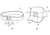
- FIG. 2 shows an example of a wearing tool to which the face-to-face interaction device 10 of the embodiment is applied.
- FIG. 2A is a schematic view of the hairband type mounting device 5
- FIG. 2B is a schematic view of the cap type mounting device 6.
- the face-to-face interaction device 10 is attached at a position corresponding to the center of the forehead or the front of the head.
- the face-to-face interaction device 10 includes an infrared light emitter 111, an infrared light receiver 121, and a visible light LED (Light Emitting Diode) 131 as part of its constituent elements.
- the infrared light emitter 111 is, for example, an infrared LED that irradiates infrared light having a predetermined wavelength with a predetermined beam divergence angle.
- the output direction of the infrared light emitter 111 changes according to the direction of the face of the wearer wearing the wearing device 5 or 6.
- the infrared light receiver 121 is a light receiving element (photodiode) having sensitivity to light having the same wavelength as that of the infrared light emitter 111, for example.
- the infrared light receiver 121 is disposed so as not to receive light from the infrared light emitter 111 installed in the same face-to-face interaction device 10 and receives only infrared light from other face-to-face interaction devices.
- the light receiving range of the infrared light receiver 121 changes according to the orientation of the wearer's face. When the infrared receiver 121 is within the directivity range of another face-to-face interaction device worn by a third party, the infrared light receiver 121 receives infrared light from the other face-to-face interaction device.
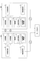
- FIG. 3 is a functional configuration diagram of the face-to-face interaction device 10 according to the first embodiment
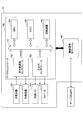
- FIG. 4 is a hardware configuration diagram of the face-to-face interaction device 10.
- FIG. 3 shows a pair of face-to-face interaction devices 10A and 10B. Since the face-to-face interaction devices 10A and 10B have the same configuration, description will be given focusing on one of them.
- the infrared transmission unit 11 transmits an infrared signal including identification information of its own device with a predetermined directivity.
- the identification information is, for example, an address code unique to the face-to-face interaction device 10A.
- the infrared receiving unit 12 receives an infrared signal from the other face-to-face interaction device 10B, extracts information included in the received infrared signal, and supplies the information to the control unit 15.
- the gaze determination unit 16 of the control unit 15 determines whether the information supplied from the infrared receiving unit 12 includes the identification information of the own device together with the identification information of the facing interaction device 10B that is the transmission source of the infrared signal. To do.
- the control unit 15 sends an output instruction to the gaze notification unit 13.
- the gaze notification unit 13 outputs visible light, a melody, a voice message, and the like in accordance with an output instruction from the control unit 15.
- the control unit 15 also detects the identification information of the facing interaction device 10B when the infrared receiving unit 12 receives the infrared signal from the other facing interaction device 10B, and the identification information of the own device and the identification information of the facing interaction device 10B.
- a transmission signal including The control unit 15 supplies a transmission instruction for the generated transmission signal to the infrared transmission unit 11.
- the face-to-face information management part 17 of the control part 15 is based on the transmission / reception by the infrared transmission part 11 and the infrared reception part 12, such as a gaze person (face-to-face partner), the number of gaze persons, a gaze time, a gaze start timing, and a gaze frequency. Record and manage information.
- the wireless communication unit 14 transmits the information acquired by the face-to-face interaction device 10A to the server or the PC at regular time intervals or at an arbitrary timing.
- the face-to-face interaction device 10B transmits the acquired information to the server or the PC.
- the server or the PC is not essential for the present invention, and the analysis or the like may be performed by exchanging the face-to-face information acquired between the plurality of face-to-face interaction devices 10.
- FIG. 4 is a hardware configuration diagram of the face-to-face interaction device 10.
- the face-to-face interaction device 10 includes an infrared light emitter 111, an infrared light receiver 121, a visible LED 131, a speaker 132, a wireless communication module 140, and a microcontroller 150.
- the infrared emitter 111 and the infrared receiver 121 are the same as the infrared emitter 111 and the infrared receiver 121 described with reference to FIG.
- the microcontroller 150 includes an infrared communication interface 152, an input / output interface 153, a CPU (Central Processing Unit) 154, a memory 155, and a storage device 156, and these electronic components are connected via a bus 151. Are interconnected.
- a CPU Central Processing Unit
- the infrared communication interface 152 generates an infrared signal having a predetermined communication speed (for example, 50 Hz) and a modulation method, and converts the received infrared signal into a predetermined signal level.
- Information included in the signal received by the infrared receiver 121 is input to the microcontroller 150 via the infrared communication interface 152 and processed.
- Information generated or processed by the microcontroller 150 is connected to the input of the infrared emitter 111 via the infrared communication interface 152.
- the function of the infrared transmitter 11 in FIG. 3 is realized by the infrared communication interface 152 and the infrared light emitter 111.
- the function of the infrared receiver 12 shown in FIG. 3 is realized by the infrared communication interface 152 and the infrared receiver 121.
- the memory 155 includes ROM (Read Only Memory) and RAM (Random Access Memory) not shown.
- the storage device 156 is an SSD (Solid State Drive), for example, and stores an application program that realizes the basic operation of the face-to-face interaction device 10.
- the CPU 154 reads out and executes programs and data stored in the storage device 156 and the memory 155 as necessary, and controls the overall operation of the face-to-face interaction device 10.
- the microcontroller 150 including the CPU 154, the memory 155, and the storage device 156 implements the function of the control unit 15 in FIG.
- the visible LED 131 and the speaker 132 are an example of the gaze notification unit 13 in FIG. 2 and are connected to the microcontroller 150 via the input / output interface 153.
- the CPU 154 controls the lighting state of the visible LED 131 and the output state of the speaker 132. When it is determined that the information included in the transmitted / received infrared signal satisfies a predetermined condition, the CPU 154 turns on the visible LED 131 or outputs sound, melody, or the like from the speaker 132.
- the wireless communication module 140 is interconnected with the microcontroller 150 and transmits / receives information to / from an external server or PC.
- the face-to-face interaction device 10 and an external server or PC are connected by Per-to-Peer (P2P) or Machine-to-Machine (M2M). It may be connected via.
- P2P Per-to-Peer
- M2M Machine-to-Machine
- the server or the PC is not essential for the present invention.
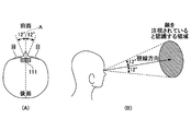
- FIG. 5 to 7 are diagrams for explaining the relationship between gaze or face-to-face recognition and the beam divergence angle of the infrared light emitter 111.
- FIG. 5A the half-value angle of the directivity or beam spread of the infrared light emitter 111 is set to a range in which the speaker who is talking recognizes his / her face.
- the half-value angle of beam spread is the angle at which the illuminance on the optical axis A is normalized and the maximum illuminance is 100% (or 1), and the illuminance is 50% when tilted in the direction of spreading from the optical axis.
- beam divergence angle refers to the half-value angle of beam divergence.
- an area in the range of 12 ° ⁇ 2 ° and ⁇ 12 ° ⁇ 2 ° from the center of the person's line of sight recognizes that the talking speaker is watching his face. It is the range to do. If the infrared light receiver 121 of the face-to-face interaction device 10A can receive the infrared light from the infrared light emitter 111 of the other face-to-face interaction device 10B within a range where the beam divergence angle is within 12 ° ⁇ 2 °, It can be considered that the face is being watched or faced.
- the infrared emitter 111 is, for example, a beam divergence angle or directivity of 9 ° or more and 20 ° or less.
- FIG. 7 is a diagram for explaining the basis of the upper limit value of the beam divergence angle ⁇ .
- the circular mark 61 and the human face photograph 62 are arranged on the wall, and the head of the subject is fixed at a position 1.2 meters away from the circular mark 61.
- the distance of 1.2 meters is a distance that a person generally meets and talks.
- FIG. 7B shows the results of examining 20 subjects in which range of photographs 62 can be recognized as being in a natural state without changing the orientation of the face.
- the sex and age of the subjects vary (12 men, 8 women, age 22-58).
- the beam divergence angle ⁇ of the infrared light emitter 111 is set to 20 ° or less with a width.
- the beam divergence angle ⁇ may be set to 15 ° or less, 12 ° or less, and the like.
- the faces are facing each other, but it is not without the case that the line of sight is outside the ⁇ 15 ° region. Such an unnatural state rarely occurs in the left-right direction and the upward direction, but may occur when looking down with his eyes turned down.
- the range in which infrared communication is established is determined as the range in which gaze or face-to-face is established, excluding the actual gaze direction.
- FIG. 8 is a sequence diagram between the face-to-face interaction devices 10A and 10B of the first embodiment.
- the infrared transmission unit 11 transmits an infrared signal including identification information (ID # 1) of the own device at a predetermined beam divergence angle (S11).
- ID # 2 identification information
- S11 predetermined beam divergence angle
- S12 predetermined beam divergence angle
- Infrared signals are transmitted at intervals of, for example, several milliseconds to several tens of milliseconds.
- the infrared signal transmitted from the face-to-face interaction device 10A is the face-to-face interaction device 10B. (S13).
- the control unit 15 of the face-to-face interaction device 10B extracts the identification information of ID # 1 from the received infrared signal, and generates an infrared signal including the extracted identification information ID # 1 and the identification information ID # 2 of the own device ( S14), transmitted from the infrared transmitter 11 (S15). With the reception of the infrared signal in S13, the face-to-face interaction apparatus 10B determines whether or not the identification information ID # 2 of the self-apparatus is included in the received signal in S14. Then, the identification ID # 2 of the own device is not included.
- the infrared signal transmitted from the face-to-face interaction device 10B is the face-to-face interaction device 10A. (S15).
- the face-to-face interaction device 10A determines whether or not the identification information ID # 1 of the device itself is included in the received infrared signal. In this case, since the identification information ID # 1 is included (S16), it is determined that the meeting is established, and the visible LED 131 is turned on (S17). At the same time, the transmission source identification information ID # 2 included in the infrared signal is recorded in the memory 155 together with the reception start date and time. By turning on the visible LED 131 of the face-to-face interaction device 10A, the wearer of the face-to-face interaction device 10B can recognize that he was able to face the opponent.
- the lighting of the visible LED 131 is a kind of reward for the wearer of the face-to-face interaction device 10B and can be a motivation to continue face-to-face. For people with developmental disabilities, face-to-face with other people is difficult, but by turning on the other party's visible LED 131, you can get a sense of accomplishment that you have faced the other person, and continue to try and face-to-face It is an opportunity to encourage motivation to try.
- the face-to-face interaction device 10A transmits an infrared signal including the identification information ID # 1 of the own device and the identification information ID # 2 of the detected partner device (face-to-face interaction device 10B) (S18).
- the visible LED 131 When the face-to-face interaction device 10B detects its own identification information ID # 2 in the received infrared signal (S19), the visible LED 131 is turned on (S20).
- the visible LED 131 can be a motivation for continuing the face-to-face for the wearer of the face-to-face interaction device 10A.
- FIG. 9 is an example of an operation flow of the control unit 15 of the face-to-face interaction device 10.
- the control unit 15 determines whether an infrared signal is received (S31). If an infrared signal has been received (YES in S31), it is determined whether the received infrared signal contains identification information of the device itself (S32). When the identification information of the own device is included (YES in S32), a transmission signal including the identification information of the partner device and the own device is transmitted (S34), and the gaze notification unit 13 including the visible LED 131, the speaker 132, and the like. Is turned on (S33).
- the transmission information is generated by adding the identification information of the own device to the identification information of the counterpart device included in the received infrared signal.
- the infrared signal is transmitted (S34), and the process returns to S31.
- the face-to-face interaction device 20 mounted on the mounting tool 1 includes, in addition to the infrared light emitter 111, the infrared light receiver 121, and the visible LED 131, a second infrared light emitter 221 and second infrared light receivers 222a and 222b. Visible LEDs 231a and 231b.
- the pair of visible LEDs 231a and 231b are electrically connected to the main body 120 of the face-to-face interaction device 20 and are disposed on both sides of the main body. Instead of the visible LEDs 231a and 231b, a pair of speakers 232a and 232b may be arranged.
- the gaze determining unit 16 is visible when the information from the first infrared receiving unit 12 is not acquired but the identification information of the own device is included in the information from the second infrared receiving unit 22.
- a second output instruction is sent to the optical output unit 23 or the audio output unit 25.
- the second output instruction is an output instruction to the visible LEDs 231a and 231b (or speakers 232a and 232b) arranged on both sides of the main body 120 in FIG.
- the control unit 45 instructs the audio output unit 25 to output from which speaker.
- the audio output unit 25 may output a melody or the like from any of the speakers 232a and 232b, or may output a message such as “turn to the right” with an animation voice.
- the voice message is a face-to-face motive for the other party and also a face-to-face motive for the wearer. By facing the directions guided by the voice messages, it becomes easier to face each other.
- step S45 If the first wavelength signal is not received in step S42 (NO in S42), it is determined whether or not the second wavelength signal is received (S45). When the signal of the second wavelength is received (YES in S45), the light receiving direction is detected (S46), and visible light or voice / melody is output from the LED 231 or the speaker 232 according to the light receiving direction (S47). If the second wavelength signal is not received (NO in S45), the process returns to S41 and is repeated.
- FIG. 14 is a diagram illustrating another application example.
- the face-to-face interaction device 10 or 20 of the embodiment can be applied not only to face-to-face interaction between a human and a human but also to face-to-face interaction between a human and a robot or a doll as shown in FIG.
- the face-to-face interaction device 10 or 20 of the embodiment it is possible to contribute to the growth of children and the development of sociality. For example, when the child can face the robot (or doll), the visible LED embedded in the center of the forehead of the robot or doll may be lit. Or it is good also as a structure which outputs a voice message, when it can face.
- the structure which transmits / receives infrared rays of two types of wavelengths in 2nd Embodiment replaces with the structure which transmits / receives infrared rays of two types of wavelengths in 2nd Embodiment, and it has comprised so that the situation of being "seen” by others can be recognized using infrared rays of one type of wavelengths. Also good.
- two light receiving elements having sensitivity to infrared rays of the same wavelength but having different light receiving angles may be used.
- one of the two light receiving elements has the same light receiving angle as the beam divergence angle to be transmitted
- the other light receiving element has a beam divergence to be transmitted.
- the light receiving angle is wider than the angle.
Landscapes
- Engineering & Computer Science (AREA)
- Physics & Mathematics (AREA)
- Theoretical Computer Science (AREA)
- General Physics & Mathematics (AREA)
- General Engineering & Computer Science (AREA)
- Educational Technology (AREA)
- Educational Administration (AREA)
- Business, Economics & Management (AREA)
- Health & Medical Sciences (AREA)
- Audiology, Speech & Language Pathology (AREA)
- Electromagnetism (AREA)
- Computer Networks & Wireless Communication (AREA)
- Signal Processing (AREA)
- General Health & Medical Sciences (AREA)
- Human Computer Interaction (AREA)
- Optical Communication System (AREA)
- Electrically Operated Instructional Devices (AREA)
- User Interface Of Digital Computer (AREA)
Abstract
注視の検出と対面インタラクションの促進を実現する装置を提供する。対面インタラクション装置は、第1のビーム広がり角で第1波長の赤外線信号を送信する第1赤外線送信部と、他の装置から前記第1波長の赤外線信号を受信する第1赤外線受信部と、対面の検出を知らせる通知手段と、受信された赤外線信号に、前記他の装置の識別情報と自装置の識別情報とが含まれているか否かを判断し、前記他の装置の識別情報と自装置の識別情報が含まれている場合に、前記通知手段をオンにする制御部とを有する。
Description
本発明は、対面インタラクション装置とこれを用いた装着デバイス、及び対面促進方法に関する。
対面インタラクションは人間の社会行動の基本的な行為である。対面インタラクションは、言葉によるバーバルコミュニケーションだけでなく、動作、表情、ジェスチュアなどによるコミュニケーションも含む。他者と対面し交流することで、自分の体験を他者と共有したり、他人の立場を考えることができる。
一般に、自閉症などの発達障害を有する者は、正面から相手と対面することが困難であると言われている。発達障害児の指導やグループセラピーで、相手とのインタラクションを促進することで、コミュニケーション能力や社会性の改善が試みられている。
画像データから顔の向きを判別する技術(たとえば、特許文献1参照)や、画像データに含まれる顔正面の情報に基づいて注視者を判別する手法(たとえば、特許文献2参照)が提案されている。
また、赤外線通信等の通信手段を備えたロボット装置同士が向き合った際に、互いに情報を交換したりあいさつ等の所定の動作を行うロボット装置が知られている(たとえば、特許文献3参照。さらに、赤外線通信手段とレーザ発光器を有するモジュールを3個以上用いて閉空間を形成する幾何学図形を描写するモジュールが提案されている(たとえば、特許文献4参照)。
他方、対面していると認識し得る注視の角度を実験的に求めた研究がなされている(非特許文献1参照)。
"Measuring K-degree Facial Interaction between Robot and Children with Autism Spectrum Disorders", Yadon Pan, Masakazu Hirokawa and Kenji Suzuki, Proceedings of the 24th IEEE International Symposium on Robot and Human Interactive Communication (RO-MAN), pp. 48-53, 2015
カメラから得られた画像を利用して顔認識を行う手法は、画像処理の時間が必要でありデータの取得頻度が低下する。コミュニケーション時には、瞬間的な顔の動きや注意の逸れが生じるため、画像データ取得頻度が低下すると、注視情報を十分に取得することができない。また、顔の向きと視線は必ずしも一致しないことから、対面しているか否かを即座に判断することは難しい。
さらに、対面しているか否かを判断するだけではなく、相手と顔を見合わせる動作や、対面での相互インタラクションを促進できる装置が望まれる。
そこで、本発明は、簡便な注視の検出と対面インタラクションの促進を実現する装置を提供することを課題とする。
上記目的を達成するために、本発明の第1の態様において、対面インタラクション装置は、
第1のビーム広がり角で第1波長の赤外線信号を送信する第1赤外線送信部と、
他の装置から前記第1波長の赤外線信号を受信する第1赤外線受信部と、
対面の検出を知らせる通知手段と、
受信された赤外線信号に、前記他の装置の識別情報と自装置の識別情報とが含まれているか否かを判断し、前記他の装置の識別情報と自装置の識別情報が含まれている場合に、前記通知手段をオンにする制御部と、
を有する。
第1のビーム広がり角で第1波長の赤外線信号を送信する第1赤外線送信部と、
他の装置から前記第1波長の赤外線信号を受信する第1赤外線受信部と、
対面の検出を知らせる通知手段と、
受信された赤外線信号に、前記他の装置の識別情報と自装置の識別情報とが含まれているか否かを判断し、前記他の装置の識別情報と自装置の識別情報が含まれている場合に、前記通知手段をオンにする制御部と、
を有する。
上記構成により、簡便に注視を検出して対面インタラクションを促進することが可能になる。
以下、本発明の実施形態について、添付図面を参照して説明する。
<概要>
図1は、本発明の実施形態の基本概念を説明する図である。実施形態では、カメラを使用せずに、赤外線により対面または相手からの顔への注視を検出する。対面または注視の検出結果に基づいて、対面あるいは他者への注視を促進、継続させる構成を提供する。より具体的には、所定の指向性を有する赤外線通信手段(図1において「IR」と表記)を身体の一部、たとえば額の中央や、頭部前面の中央などに装着する。相手から受信する赤外線信号中に、相手側装置の識別情報とともに自装置の識別情報が含まれている場合に、相手からの顔への注視が検出されたと判断し、注視の検出を外部的に通知する。注視の検出の詳細については後述する。
<概要>
図1は、本発明の実施形態の基本概念を説明する図である。実施形態では、カメラを使用せずに、赤外線により対面または相手からの顔への注視を検出する。対面または注視の検出結果に基づいて、対面あるいは他者への注視を促進、継続させる構成を提供する。より具体的には、所定の指向性を有する赤外線通信手段(図1において「IR」と表記)を身体の一部、たとえば額の中央や、頭部前面の中央などに装着する。相手から受信する赤外線信号中に、相手側装置の識別情報とともに自装置の識別情報が含まれている場合に、相手からの顔への注視が検出されたと判断し、注視の検出を外部的に通知する。注視の検出の詳細については後述する。
図2は、実施形態の対面インタラクション装置10を適用した装着具の例を示す。図2(A)はヘアバンド型の装着デバイス5、図2(B)はキャップ型の装着デバイス6の概略図である。装着デバイス5及び6では、額または頭部前面の中央に相当する位置に、対面インタラクション装置10が取り付けられている。
対面インタラクション装置10は、その構成要素の一部に、赤外線発光器111と、赤外線受光器121と、可視光LED(Light Emitting Diode;発光ダイオード)131を有する。赤外線発光器111は、たとえば、所定の波長の赤外光を所定のビーム広がり角で照射する赤外線LEDである。赤外線発光器111の出力の向きは、装着デバイス5または6を装着する装着者の顔の向きにしたがって変化する。
赤外線受光器121は、たとえば赤外線発光器111と同じ波長の光に感度を有する受光素子(フォトダイオード)である。赤外線受光器121は、同じ対面インタラクション装置10に設置されている赤外線発光器111からの光を受光しないように配置され、他の対面インタラクション装置からの赤外光だけを受光する。装着者の顔の向きに応じて、赤外線受光器121の受光範囲が変化する。第三者が装着する他の対面インタラクション装置の指向性の範囲内に赤外線受光器121があるときに、赤外線受光器121は、当該他の対面インタラクション装置から赤外光を受信する。
可視光LED131は、たとえばグリーンLEDであり、対面インタラクション装置10で装着者の顔への注視が検出されたときに点灯する。注視が検出されたときとは、他の対面インタラクション装置の指向性の範囲内に、着目している対面インタラクション装置の赤外線受光器121が存在し、2つの対面インタラクション装置間で赤外線通信が成立するときをいう。赤外線通信の範囲は、たとえば2.5メートルとする。
可視光LED131は、顔への注視の検出を外部的に通知する一手段なので、可視光LED131に替えて、あるいは可視光LED131とともに、所定のメロディや音声を出力するスピーカを用いてもよい。可視光LED131やスピーカから出力される光や音声は、注視の検出を相手方に通知するだけではなく、注視者の注意を惹きつけ、注視あるいは対面状態を継続させる役割を果たす。
<第1実施形態>
図3は、第1実施形態の対面インタラクション装置10の機能構成図、図4は対面インタラクション装置10のハードウェア構成図である。図3では、一対の対面インタラクション装置10Aと10Bを示している。対面インタラクション装置10Aと10Bは同じ構成であるため、いずれか一方に着目して説明する。
<第1実施形態>
図3は、第1実施形態の対面インタラクション装置10の機能構成図、図4は対面インタラクション装置10のハードウェア構成図である。図3では、一対の対面インタラクション装置10Aと10Bを示している。対面インタラクション装置10Aと10Bは同じ構成であるため、いずれか一方に着目して説明する。
図3において、対面インタラクション装置10Aは、赤外線(IR:infrared)送信部11と、赤外線(IR)受信部12と、注視通知部13と、無線通信部14と、制御部15を有する。制御部15は、注視判断部16と、対面情報管理部17を有する。
赤外線送信部11は、自装置の識別情報を含む赤外線信号を所定の指向性で送信する。識別情報は、たとえば対面インタラクション装置10Aに固有のアドレスコードである。赤外線受信部12は、他の対面インタラクション装置10Bからの赤外線信号を受信し、受信した赤外線信号に含まれる情報を取り出して制御部15へ供給する。
制御部15の注視判断部16は、赤外線受信部12から供給される情報に、赤外線信号の送信元の対面インタラクション装置10Bの識別情報とともに、自装置の識別情報が含まれているか否かを判断する。自装置の識別情報が含まれている場合は、制御部15は注視通知部13に出力指示を送る。注視通知部13は、制御部15からの出力指示に従って可視光、メロディ、音声メッセージなどを出力する。
制御部15はまた、赤外線受信部12が他の対面インタラクション装置10Bから赤外線信号を受信したときに、対面インタラクション装置10Bの識別情報を検出し、自装置の識別情報と対面インタラクション装置10Bの識別情報とを含む送信信号を生成する。制御部15は、生成した送信信号の送信指示を赤外線送信部11に供給する。
制御部15の対面情報管理部17は、赤外線送信部11と赤外線受信部12による送受信に基づいて、注視者(対面相手)、注視者の数、注視時間、注視の開始タイミング、注視頻度などの情報を記録し、管理する。
無線通信部14は、一定時間ごとに、または任意のタイミングで、対面インタラクション装置10Aが取得した情報を、サーバまたはPCに送信する。対面インタラクション装置10Bも、同様に取得した情報をサーバまたはPCに送信する。各インタラクション装置10からの情報をサーバまたはPCに集約することで、3人以上の装着者間での対面または注視の状態を分析し、たとえば発達障害の治療やセラピーに反映することができる。もっとも、サーバまたはPCは本発明にとって必須ではなく、複数の対面インタラクション装置10間で取得した対面情報を交換して、分析等を行ってもよい。
図4は、対面インタラクション装置10のハードウェア構成図である。対面インタラクション装置10は、赤外線発光器111、赤外線受光器121、可視LED131、スピーカ132、無線通信モジュール140、及びマイクロコントローラ150を含む。赤外線発光器111と赤外線受光器121は、図2を参照して説明した赤外線発光器111および赤外線受光器121と同様のものである。
マイクロコントローラ150は、赤外線通信インタフェース152と、入出力インタフェース153と、CPU(Central Processing Unit;中央演算装置)154と、メモリ155と、記憶装置156を有し、これらの電子部品がバス151を介して相互接続されている。
赤外線通信インタフェース152は、所定の通信速度(たとえば50Hz)と変調方式の赤外信号を生成し、また、受信した赤外線信号を所定の信号レベルに変換する。赤外線受光器121で受信された信号に含まれる情報は、赤外線通信インタフェース152を介してマイクロコントローラ150に入力され、処理される。マイクロコントローラ150で生成または処理された情報は、赤外線通信インタフェース152を介して、赤外線発光器111の入力に接続される。
赤外線通信インタフェース152と赤外線発光器111で、図3の赤外線送信部11の機能が実現される。赤外線通信インタフェース152と赤外線受光器121で、図3の赤外線受信部12の機能が実現される。
メモリ155は、図示しないROM(Read Only Memory)やRAM(Random Access Memory)を含む。記憶装置156は、たとえばSSD(Solid State Drive;固体ドライブ)であり、対面インタラクション装置10の基本動作を実現するアプリケーションプログラムを格納する。CPU154は、必要に応じて記憶装置156やメモリ155に記憶されたプログラムやデータを読み出して実行し、対面インタラクション装置10の動作全体を制御する。CPU154、メモリ155、及び記憶装置156を含むマイクロコントローラ150は、図3の制御部15の機能を実現する。
可視LED131とスピーカ132は、図2の注視通知部13の一例であり、入出力インタフェース153を介してマイクロコントローラ150に接続される。CPU154は可視LED131の点灯状態やスピーカ132の出力状態を制御する。送受信される赤外線信号に含まれる情報が所定の条件を満たすと判断された時に、CPU154は可視LED131を点灯させ、あるいはスピーカ132から音声、メロディ等を出力させる。
無線通信モジュール140は、マイクロコントローラ150と相互接続され、外部のサーバまたはPCとの間で情報の送受信を行う。図4の構成では、対面インタラクション装置10と外部のサーバまたはPCは、Per-to-Peer(P2P)またはMachine-to-Machine(M2M)で接続されているが、図示しない小型無線基地局装置を介して接続されていてもよい。なお、上述したように、サーバまたはPCは本発明にとって必須ではない。近距離無線通信機能を有する無線通信モジュール140により複数の対面インタラクション装置10間で情報を交換し、マイクロコントローラ150で処理、解析することで、複数の装着者間での注視の状態を分析してもよい。
図5~図7は、注視または対面の認識と、赤外線発光器111のビーム広がり角の関係を説明する図である。図5(A)に示すように、赤外線発光器111の指向性またはビーム広がりの半値角を、会話中の話者が自らの顔が注視されていると認識する範囲に設定する。ビーム広がりの半値角とは、光軸A上の照度を正規化して照度の最大を100%(または1)として、光軸から広がる方向に傾いたときに照度が50%となるときの角度をいう。本明細書および特許請求の範囲で、「ビーム広がり角」というときは、ビーム広がりの半値角を指すものとする。
図5(B)に示すように、人の視線方向の中心から12°±2°及び-12°±2°の範囲にある領域は、会話中の話者が顔を注視されていると認識する範囲である。対面インタラクション装置10Aの赤外線受光器121が、他の対面インタラクション装置10Bの赤外線発光器111からの赤外光を、ビーム広がり角が12°±2°以内の範囲で受光できた場合は、相手から顔を注視されている、あるいは対面しているとみなすことができる。
ビーム広がり角θに下限はなく、指向性が高いほど注視判断の正確性が高くなる。実施形態では、赤外線LEDの製造上の技術的限界とコストの観点、及び注視検出の余裕を持たせる観点から、赤外線発光器111は一例として9°以上、20°以下のビーム広がり角または指向性を有する。
図6は、他者と対面するときの状態を示す。図6(A)は理想的な対面状態であり、顔と顔が真正面に向き合って、視線が相手の顔の中心に向けられている。もっとも、このような場合は稀である。通常は、図6(B)に示すように、顔の向きや視線が多少ずれても相手の顔はなおも視界の主要領域に入っており、対面していると認識することができる。赤外線発光器111のビーム広がり角θは、人が対面していると認識できる最大の傾き角度θに相当する。
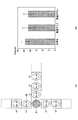
図7は、ビーム広がり角θの上限値の根拠を説明する図である。図7(A)のように円形マーク61と人の顔の写真62を壁に並べ、円形マーク61から1.2メートル離れた位置に被験者の頭部を固定する。1.2メートルというのは、一般に人が対面して会話等を行う距離である。
図7(B)は、顔の向きを変えずに、どの範囲の写真62と自然な状態で対面していると認識できるかを被験者20人に対して調べた結果を示す。被験者の性別、年齢は様々である(男性12名、女性8名、年齢22~58歳)。
垂直方向の角度に比べて水平方向の角度がやや広いが、垂直方向と水平方向に12°±2°以内の範囲であれば、対面していると認識されることがわかる。この結果から、実施形態では、赤外線発光器111のビーム広がり角θを、幅をもたせて20°以下に設定する。もっとも、対面インタラクション装置の装着者の年齢によっては、たとえばビーム広がり角θを15°以下、12°以下等に設定してもよい。
さらに、確認実験として、対面インタラクション装置10Aを装着した被験者Aと、対面インタラクション装置10Bを装着した被験者Bの間で、赤外線送受信による可視LEDの点灯と、互いの対面状態の認識とが一致しているかどうかを調べた。公正さを担保するため、2名の被験者の間に、判定者を介在させた。20名の被験者に対して、「相手のLEDが光ったとき、相手と対面していると感じるか否か」という質問を提示し、回答を収集したところ、84%の整合率が得られている。
なお、顔は対向しているが視線が±15°の領域外に向いている場合が無いわけではない。このような不自然な状態は、左右方向と上方向ではほとんど生じないが、目を伏せて下を見ている場合が起こり得る。実施形態では、対面インタラクション装置10にて注視または対面を定量的に判断する目的で、実際の視線の向きを除外して、赤外線通信が成立する範囲を注視または対面が成立する範囲として判断する。
図8は、第1実施形態の対面インタラクション装置10Aと10Bの間のシーケンス図である。対面インタラクション装置10Aの電源がオンにされると、赤外線送信部11は自装置の識別情報(ID#1)を含む赤外線信号を所定のビーム広がり角で送信する(S11)。同様に、対面インタラクション装置10Bの電源がオンにされると、対面インタラクション装置10Bの赤外線送信部は、自装置の識別情報(ID#2)を含む赤外線信号を所定のビーム広がり角で送信する(S12)。赤外線信号は、たとえば数ミリ秒から数十ミリ秒の間隔で送信される。
対面インタラクション装置10Bの赤外線受光器121が、対面インタラクション装置10Aの赤外線発光器111のビーム広がり角θの範囲内に位置するときに、対面インタラクション装置10Aから送信された赤外線信号は、対面インタラクション装置10Bで受信される(S13)。
対面インタラクション装置10Bの制御部15は、受信した赤外線信号からID#1の識別情報を抽出し、抽出した識別情報ID#1と自装置の識別情報ID#2を含む赤外線信号を生成して(S14)、赤外線送信部11から送信する(S15)。S13での赤外線信号の受信にともなって、対面インタラクション装置10Bは、S14で受信信号中に自装置の識別情報ID#2が含まれているか否かを判断するが、対面が成立する直前の状態では、自装置の識別ID#2は含まれていない。
対面インタラクション装置10Aの赤外線受光器121が、対面インタラクション装置10Bの赤外線発光器111のビーム広がり角θの範囲内に位置するときに、対面インタラクション装置10Bから送信された赤外線信号は、対面インタラクション装置10Aで受信される(S15)。
対面インタラクション装置10Aは、受信した赤外線信号中に自装置の識別情報ID#1が含まれているか否かを判断する。この場合、識別情報ID#1が含まれているので(S16)、対面が成立していると判断して、可視LED131を点灯する(S17)。これとともに、赤外線信号に含まれる送信元の識別情報ID#2を、受信開始日時とともにメモリ155に記録する。対面インタラクション装置10Aの可視LED131が点灯することで、対面インタラクション装置10Bの装着者は、自分が相手と対面できたことを認識することができる。
可視LED131の点灯は、対面インタラクション装置10Bの装着者にとって、一種の褒賞であるとともに、対面を継続させる動機付けとなり得る。発達障害者にとって、他者との対面は困難をともなうが、相手方の可視LED131が点灯することで、相手と対面できたという達成感を得ることができ、対面しようとする試みや、対面を継続しようとする意欲を促す契機となる。
対面インタラクション装置10Aは、自装置の識別情報ID#1と、検出した相手装置(対面インタラクション装置10B)の識別情報ID#2を含む赤外線信号を送信する(S18)。
対面インタラクション装置10Bは、受信した赤外線信号中に自装置の識別情報ID#2を検出すると(S19)、可視LED131を点灯する(S20)。この可視LED131は、対面インタラクション装置10Aの装着者にとっての対面継続の動機づけとなり得る。
受信した赤外線信号中に自装置の識別情報を検出できてきる間は、対面状態が継続しているとみなすことができる。
対面インタラクション装置10Aにおいて、受信した赤外線信号中に自装置の識別情報ID#1が含まれなくなった場合、あるいは対面インタラクション装置10Bからの赤外線信号を受信しなくなった場合は(S21)、対面インタラクション装置10Aは可視LED131を消灯する(S23)。この場合、対面インタラクション装置10Bの装着者は、もはや対面インタラクション装置10Aの装着者に向き合っていないとみなされるからである。
同様に、対面インタラクション装置10Bにおいて、受信した赤外線信号中に自装置の識別情報ID#2が含まれなくなった場合、あるいは対面インタラクション装置10Aからの赤外線信号を受信しなくなった場合は(S22)、対面インタラクション装置10Bは可視LED131を消灯する(S24)。
可視LED131の点灯は、注視者(対面者)に対する褒賞として機能するが、注視(対面)検出を外部的に通知する手段としては、可視光の出力に限定されない。受信赤外線信号中に自装置の識別情報が含まれる場合に、短いメロディ音やアニメーションのキャラクターの音声によるメッセージを出力してもよい。
図9は、対面インタラクション装置10の制御部15の動作フローの一例である。制御部15は、赤外線信号が受信されているか否かを判断する(S31)。赤外線信号が受信されている場合は(S31でYES)、受信した赤外線信号中に自装置の識別情報が含まれているか否かを判断する(S32)。自装置の識別情報が含まれている場合は(S32でYES)、相手装置と自装置の識別情報を含む送信信号を送信するとともに(S34)、可視LED131、スピーカ132等を含む注視通知部13の出力をオンにする(S33)。受信した赤外線信号中に自装置の識別情報が含まれていない場合は(S32でNO)、受信赤外線信号に含まれる相手装置の識別情報に自装置の識別情報を追加して送信信号を生成し、赤外線信号を送信して(S34)、S31に戻る。
制御部15は、受信した赤外線信号に自装置の識別情報が含まれている場合、送信元の識別情報(注視者)、認識した注視者の数、注視時間(対面継続時間)、注視タイミング、注視頻度等の情報を対面情報管理部17に記録し、管理する。これらの情報の少なくともひとつに基づいて、注視通知部13の注視通知パターンを変更してもよい(S35)。たとえば、複数の可視LEDを配置して、一定時間以上注視が継続した場合に、LEDの点灯パターン、輝度、発光色等を変更してもよい。あるいは、複数の対面インタラクション装置からの注視が検出された場合は、人数に応じて可視LEDの色を変えてもよい。このような通知パターンの変化も、注視者にとって対面継続の動機づけとなり得る。スピーカ131を用いる場合は、出力するメロディ、音声メッセージなどを変化させてもよい。
図10は、対面情報管理部17で管理される対面情報の一例を示す。たとえば、発達障害児のグループセラピーで、セラピストの指導で児童が共同作業や遊びに従事する際に、対面相手が入れ替わったり、複数の児童から注視される場合がある。対面情報は、注視者ごとに、注視が検出された日時、注視継続時間、平均注視頻度等の情報を記録する。図示はしないが、注視者ごとに、平均注視時間とその推移情報、平均注視頻度の推移情報などを記録してもよい。また、相手装置からの識別情報のみを検出したタイミング、受信期間なども合わせて記録、管理してもよい。
児童Aが装着する対面インタラクション装置10の対面情報管理部17は、たとえば、児童B、C、D、…との間の対面情報を管理する。児童Bからの赤外線信号中に自装置の識別情報を検出した場合は、児童Bと関連付けて注視の検出情報が記録される。各児童について、1セッション当たりの平均注視回数を記録してもよい。たとえば、週ごと、月ごとに平均注視回数を記録することで、症状の改善状況を知ることができる。また、どの児童との間で対面が成立しやすいか、どの児童からの注視時間が長いか、などを分析することで、今後のセラピーの方向性に役立てることができる。
このように、第1実施形態の対面インタラクション装置10は、簡便な注視の検出と、対面インタラクションの促進を実現することができる。
<第2実施形態>
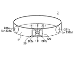
図11は、第2実施形態の対面インタラクション装置20を用いた装着デバイス7の外観図である。第2実施形態では、注視または対面を促進する効果をより高める構成を提供する。
<第2実施形態>
図11は、第2実施形態の対面インタラクション装置20を用いた装着デバイス7の外観図である。第2実施形態では、注視または対面を促進する効果をより高める構成を提供する。
装着具1に装着された対面インタラクション装置20は、赤外線発光器111、赤外線受光器121、可視LED131に加えて、第2の赤外線発光器221と、第2の赤外線受光器222a、222bと、一対の可視LED231a及び231bを有する。一対の可視LED231a、231bは、対面インタラクション装置20の本体120と電気的に接続され、本体の両側に配置されている。可視LED231a、231bに替えて、一対のスピーカ232a、232bを配置してもよい。
第2の赤外線発光器221は、赤外線発光器111と異なる波長λ2の赤外光を、赤外線発光器111よりも広いビーム広がり角θ2で出力する。第2の赤外線受光器222a及び222bは、波長λ2の赤外光に感度を有する。図11の例では、第2の赤外線受光器222aと222bは、第1の赤外線受光器121の両側のみに配置されているが、上下左右の4か所に配置してもよい。第2の赤外線受光器222a、222bは、当該対面インタラクション装置20の第2の赤外線発光器221からの赤外光を受信しない位置に配置され、他の対面インタラクション装置からの波長λ2の赤外光だけを受光する。
第2の赤外線発光器221のビーム広がり角θ2は、第1の赤外線発光器111のビーム広がり角θ1よりも広い。そのため、第1の赤外線受光器121が他の対面インタラクション装置から波長λ1の赤外光を受光しない場合でも、第2の赤外線受光器222aと222bの一方または両方が波長λ2の赤外光を受光する場合がある。すなわち、対面インタラクション装置の装着者同士が真正面で対向していないが、対面する可能性のある角度で斜めに向き合っている状況である。
対面インタラクション装置20は、このような状況を検出した場合は、受光の方向に応じた位置の可視LED231aまたは231bを点灯し、相手の顔が注視位置に向くように促す。
図12は、第2実施形態の対面インタラクション装置20の機能構成図である。対面インタラクション装置20Aと20Bは同じ構成であるため、いずれか一方に着目して説明する。また、第1実施形態の対面インタラクション装置10と同じ構成要素には同じ符号を付けて、重複する説明を省略する。
対面インタラクション装置20Aは、第1の赤外線(IR)送信部11、第2の赤外線(IR)送信部21、第1の赤外線(IR)受信部12、第2の赤外線(IR)受信部22、可視光出力部23、音声出力部25、無線通信部14、及び制御部45を有する。制御部45は、注視判断部16と、対面情報管理部17と、受光方向判断部18を有する。可視光出力部23と音声出力部25は、図3の注視通知部13として機能するとともに、対面方向を案内するガイド部としても機能する。
第1の赤外線送信部11は、自装置の識別情報を含む第1波長λ1の赤外線信号を、第1のビーム広がり角θ1で送信する。第1の赤外線受信部12は、他の対面インタラクション装置10Bから第1波長λ1の赤外線信号を受信する。
第2の赤外線送信部21は、自装置の識別情報を含む第2波長λ2の赤外線信号を、第2のビーム広がり角θ2で送信する。第2の赤外線受信部22は、他の対面インタラクション装置10Bから第2波長λ2の赤外線信号を受信する。
第1波長λ1は、一例として810~870nmの範囲で選択される。第2波長λ2は一例として1150~1650nmの範囲で選択される。第1のビーム広がり角θ1は、上述のように20°以下であり、好ましくは15°以下、より好ましくは9°以上、12°以下の範囲である。第2のビーム広がり角θ2は、θ1より広く、たとえば、23~36°の範囲で設定される。
制御部45の注視判断部16は、第1の赤外線受信部12から供給される情報に、赤外線信号の送信元の対面インタラクション装置10Bの識別情報とともに、自装置の識別情報が含まれている場合に、可視光出力部23に第1出力指示を送る。第1出力指示は、図11で本体120の中央部に配置されている可視LED131の出力指示である。
注視判断部16は、第1の赤外線受信部12からの情報が取得されていないが、第2の赤外線受信部22からの情報中に、自装置の識別情報が含まれている場合に、可視光出力部23または音声出力部25に第2出力指示を送る。第2出力指示は、図11で本体120の両側に配置されている可視LED231a、231b(またはスピーカ232a、232b)に対する出力指示である。
受光方向判断部18は、第2の赤外線受信部22での受光方向を判断する。受光方向は公知の到来方向(AOA:Angle of Arrival)推定アルゴリズムを用いて推定することができる。到来方向推定アルゴリズムと組み合わせて、赤外線受光器222a、222bのいずれで支配的に受光されているかの判断を用いてもよい。
制御部45は、受光方向に応じて、可視光出力部23または音声出力部25に、可視LED231a、231bのどちらを光らせるかを指示する。たとえば、図11で相手から見て左側に位置する第2の赤外線受光器222aの方向、すなわち、装着者から見て右側に位置する第2の赤外線受光器222aの方向から第2波長λ2の赤外線信号を受信したときは、相手の顔が第1の赤外線受光器121の方向を向くように、相手から見て右側(装着者から見て左側)の可視LED131bを点灯させる。
相手から見て右側に位置する第2の赤外線受光器222bの方向、すなわち、装着者から見て左側に位置する第2の赤外線受光器222bの方向から第2波長λ2の赤外線信号を受信したときは、相手の顔が第1の赤外線受光器121の方向を向くように、相手から見て左側(装着者から見て右側)の可視LED131aを点灯させる。
スピーカ232a、232bを用いる場合も同様である。制御部45は音声出力部25に対していずれのスピーカから出力するかを指示する。音声出力部25は、スピーカ232a、232bのいずれかからメロディ等を出力してもよいし、アニメーションの音声で「もうちょっと右側を向いてね」等のメッセージを出力してもよい。この場合、音声メッセージは相手方にとって、対面の動機づけになるとともに、装着者にとっても対面の動機づけになる。相互に音声メッセージに案内された方向を向くことで、相手と対面しやすくなる。
第1の赤外線受信部12からの情報に自装置の識別情報が含まれ、かつ第2の赤外線受信部22からの情報にも自装置の識別情報が含まれている場合は、すでに注視または対面が成立しているとみなして、中央の可視LED131のみをオンにする。可視LED131の点灯に替えて、あるいは可視LED131の点灯とともに、スピーカ232a、232bから「対面できたね!」等の音声メッセージを出力してもよい。
このような構成により、対面や相手の顔への注視が促進され、児童や発達障害者の社会性の向上を図ることができる。
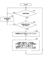
図13は、制御部45の処理フローを示す。赤外線信号が受信されたか否かを判断し(S41)、受信されていれば(S41でYES)、第1波長の信号か否かを判断する(S42)。第1波長の信号が受信されていれば(S42でYES)、自装置の識別情報が含まれているか否かを判断する(S43)。自装置の識別情報が含まれていれば、相手との間で対面が成立していると判断して、本体120の中央部に位置する可視LED131を点灯する(S45)。
ステップS42で第1波長の信号が受信されていない場合は(S42でNO)、第2波長の信号が受信されているか否かを判断する(S45)。第2波長の信号が受信されている場合は(S45でYES)、受光方向を検出し(S46)、受光方向に応じたLED231またはスピーカ232から可視光または音声・メロディを出力する(S47)。第2波長の信号も受信されていない場合は(S45でNO)、S41に戻って処理を繰り返す。
このような構成、手法により、対面の促進を向上することができる。
<その他の適用例>
図14は、その他の適用例を示す図である。実施形態の対面インタラクション装置10または20は、人間と人間の対面インタラクションだけではなく、図14(A)に示すように、人間とロボットや人形との間の対面インタラクションにも適用することができる。実施形態の対面インタラクション装置10また20を用いることで、子供の発育や社会性の育成に資することができる。たとえば、児童がロボット(または人形)と対面できたときに、ロボットや人形の額の中央部に埋め込まれている可視LEDが点灯する構成としてもよい。あるいは、対面できたときに音声メッセージを出力する構成としてもよい。
<その他の適用例>
図14は、その他の適用例を示す図である。実施形態の対面インタラクション装置10または20は、人間と人間の対面インタラクションだけではなく、図14(A)に示すように、人間とロボットや人形との間の対面インタラクションにも適用することができる。実施形態の対面インタラクション装置10また20を用いることで、子供の発育や社会性の育成に資することができる。たとえば、児童がロボット(または人形)と対面できたときに、ロボットや人形の額の中央部に埋め込まれている可視LEDが点灯する構成としてもよい。あるいは、対面できたときに音声メッセージを出力する構成としてもよい。
図14(B)は、対面インタラクション装置30をグラブ型の装着具3に適用した例として、装着デバイス8を示す。装着デバイス8は、互いの手に装着した対面インタラクション装置30間で赤外線通信が成立した場合に、レーザ光源33から可視レーザ光を照射する構成としてもよい。装着者Aの掌と、装着者Bの掌が向き合って可視レーザ光が出力される場合は、体は真正面で向かい合っていなくても、通常は、顔と顔は対向している、あるいはアイコンタクトがなされていると考えられる。
図14(B)では、装着デバイス8を同じ側の手に装着しているが、一対の装着デバイス8として構成して、一人は右手に、もう一人は左手に装着し、互いに真正面に位置して赤外線通信が確立したときに、可視レーザ光を出力する構成としてもよい。グラブ型の装着デバイス8を児童や発達障害者に適用することで、遊びの中から相手とのコミュニケーション能力や社会性を育てることができる。図14(B)の装着デバイス8を用いる場合は、防御グラスと組み合わせて装着するのが望ましい。防御グラスは可視レーザ光から眼を防御するとともに、児童にとって防御グラスの装着自体が遊びの要素となり得る。
以上、特定の実施形態に基づいて本発明を説明したが、上述した例に限定されない。たとえば、セッションルームに全体が映るビデオカメラを設置し、対面インタラクション装置10(または20)で取得されたセッション記録としての対面情報とビデオ映像を組み合わせてもよい。この場合、どのタイミングで対面が成立したか、どのような態様で対面が成されているか等を詳細に分析して、指導に反映することができる。
また、第2実施形態で2種類の波長の赤外線を送受信する構成に替えて、1種類の波長の赤外線を用いて、他者から「見られている」という状況を認識できるように構成してもよい。たとえば、対面インタラクション装置で、同一波長の赤外線に対して感度を有するが、異なる受光角を有する2つの受光素子を用いてもよい。2つの受光素子のうちの一つ(第1の受光素子)は、たとえば送信するビーム広がり角と同じ受光角度を有し、もうひとつの受光素子(第2の受光素子)は、送信するビーム広がり角よりも広い受光角度を有する。この場合、第1の赤外線受信部は、送信するビーム広がり角と同じ受光角度で赤外線信号を受信し、第2の赤外線受信部は、送信するビーム広がり角よりも広い受光角度で赤外線信号を受信する。
注視判断部16は、第1の赤外線受信部で赤外線信号は受信されていないが、第2の赤外線受信部で赤外線信号が受信されている場合に、前記出力手段をオンにして、対面の方向を案内する。
この構成により、対面成立だけでなく、本人は相手の顔の方を向いていないが、相手は本人の顔の方を見ている、という状況を識別し、出力手段を用いて、対面の方向を案内することが可能になる。
自閉症などの発達障害児の治療、指導、グループセラピーに利用することができる。また、年少者の発育、成長の補助に利用することができる。実施形態の対面インタラクション装置を用いることで、相互コミュニケーションの促進や、対人関係能力の向上に資することができる。
本件出願は、2016年6月30日に日本国特許庁に出願された特許出願第2016-131068号に基づき、その全内容を含むものである。
1,2,3 装着具
5,6,7、8 装着デバイス
10、20、30 対面インタラクション装置
11 赤外線送信部(第1の赤外線送信部)
12 赤外線受信部(第1の赤外線受信部)
13 注視通知部
14 無線通信部
15、45 制御部
16 注視判断部
17 対面情報管理部
18 受光方向判断部
21 赤外線送信部(第2赤外線送信部)
22 赤外線送信部(第2赤外線受信部)
23 可視光出力部(通知部およびガイド部)
25 音声出力部(通知部およびガイド部)
111,221 赤外線発光器
121、222a、222b 赤外線受光器
131,231a、231b 可視LED
132,232a、232b スピーカ
150 マイクロコントローラ
154 CPU
5,6,7、8 装着デバイス
10、20、30 対面インタラクション装置
11 赤外線送信部(第1の赤外線送信部)
12 赤外線受信部(第1の赤外線受信部)
13 注視通知部
14 無線通信部
15、45 制御部
16 注視判断部
17 対面情報管理部
18 受光方向判断部
21 赤外線送信部(第2赤外線送信部)
22 赤外線送信部(第2赤外線受信部)
23 可視光出力部(通知部およびガイド部)
25 音声出力部(通知部およびガイド部)
111,221 赤外線発光器
121、222a、222b 赤外線受光器
131,231a、231b 可視LED
132,232a、232b スピーカ
150 マイクロコントローラ
154 CPU
Claims (12)
- 第1のビーム広がり角で第1波長の赤外線信号を送信する第1赤外線送信部と、
他の装置から前記第1波長の赤外線信号を受信する第1赤外線受信部と、
対面の検出を知らせる通知手段と、
受信された赤外線信号に、前記他の装置の識別情報と自装置の識別情報とが含まれているか否かを判断し、前記他の装置の識別情報と自装置の識別情報が含まれている場合に、前記通知手段をオンにする制御部と、
を有する対面インタラクション装置。 - 前記第1のビーム広がり角よりも広い第2のビーム広がり角で、前記第1波長と異なる第2波長の赤外線信号を送信する第2赤外線送信部と、
前記第2波長の赤外線信号を受信する第2赤外線受信部と、
対面方向を案内するガイド部と、
をさらに有し、
前記制御部は、前記第1波長の赤外線信号が受信されていないが、前記第2波長の赤外線信号が受信されている場合に、前記ガイド部の出力をオンにすることを特徴とする請求項1に記載の対面インタラクション装置。 - 前記第1赤外線受信部は、前記第1波長に感度を有する赤外線受光器を有し、
前記第2赤外線受信部は、前記第1赤外線受信部の両側に配置され前記第2波長に感度を有する一対の赤外線受光器を有する、
ことを特徴とする請求項2に記載の対面インタラクション装置。 - 前記第2波長の赤外線信号が受信された場合に受光方向を検出する検出部、
をさらに有し、
前記制御部は、前記受光方向に応じて前記ガイド部の出力を制御することを特徴とする請求項2または3に記載の対面インタラクション装置。 - 他の装置から前記第1波長の赤外線信号を前記第1のビーム広がり角よりも広い受光角度で受信する第2赤外線受信部と、
対面方向を案内するガイド部と、
をさらに有し、
前記第1赤外線受信部は、前記第1波長の赤外線信号を前記第1のビーム広がり角と同じ受光角度で受信し、
前記制御部は、前記第1赤外線受信部で赤外線信号が受信されていないが、前記第2赤外線受信部で赤外線信号が受信されている場合に、前記ガイド部の出力をオンにすることを特徴とする請求項1に記載の対面インタラクション装置。 - 前記制御部は、前記第1赤外線受信部で受信された赤外線信号に、前記他の装置の識別情報と自装置の識別情報とが含まれている場合に対面状態を検出したと判断し、前記対面状態に関する情報を記録、管理することを特徴とする請求項1~5のいずれか1項に記載の対面インタラクション装置。
- 前記通知手段は、可視光、音声、または可視レーザ光を出力することを特徴とする請求項1~6のいずれか1項に記載の対面インタラクション装置。
- 請求項1~7のいずれか1項に記載の対面インタラクション装置と、
前記対面インタラクション装置を支持する装着具と、
を有する装着デバイス。 - 前記装着具は、ヘアバンド型、ギャップ側、またはグラブ型の装着具であることを特徴とする請求項8に記載の装着デバイス。
- 第1のビーム広がり角で第1波長の赤外線信号を送信し、
他の装置から前記第1波長の赤外線信号を受信し、
コンピュータにて、受信された赤外線信号に、前記他の装置の識別情報と自装置の識別情報とが含まれているか否かを判断し、
前記他の装置の識別情報と自装置の識別情報が含まれている場合に、出力手段をオンにして対面の成立を通知する、
ことを特徴とする対面促進方法。 - 前記第1のビーム広がり角よりも広い第2のビーム広がり角で、前記第1波長と異なる第2波長の赤外線信号を送信し、
前記他の装置から前記第2波長の赤外線信号を受信し、
コンピュータにて前記第1波長または前記第2波長が受信されているか否かを判断し、
前記第1波長の赤外線信号が受信されていないが、前記第2波長の赤外線信号が受信されている場合に、前記出力手段をオンにして、対面の方向を案内する、
ことを特徴とする請求項10に記載の対面促進方法。 - 他の装置から、前記第1のビーム広がり角と同じ受光角度で前記第1波長の赤外線信号を受信する第1赤外線受信部と、前記他の装置から、前記第1のビーム広がり角よりも広い受光角度で前記第1波長の赤外線信号を受信する第2赤外線受信部とを設け、
コンピュータにて、前記第1赤外線受信部または前記第2赤外線受信部で前記赤外線信号が受信されているか否かを判断し、
前記第1赤外線受信部で前記赤外線信号が受信されていないが、前記第2赤外線受信部で前記赤外線信号が受信されている場合に、前記出力手段をオンにして、対面の方向を案内する、
ことを特徴とする請求項10に記載の対面促進方法。
Priority Applications (1)
| Application Number | Priority Date | Filing Date | Title |
|---|---|---|---|
| JP2018525304A JPWO2018003986A1 (ja) | 2016-06-30 | 2017-06-30 | 対面インタラクション装置、これを用いた装着デバイス、及び対面促進方法 |
Applications Claiming Priority (2)
| Application Number | Priority Date | Filing Date | Title |
|---|---|---|---|
| JP2016-131068 | 2016-06-30 | ||
| JP2016131068 | 2016-06-30 |
Publications (1)
| Publication Number | Publication Date |
|---|---|
| WO2018003986A1 true WO2018003986A1 (ja) | 2018-01-04 |
Family
ID=60786008
Family Applications (1)
| Application Number | Title | Priority Date | Filing Date |
|---|---|---|---|
| PCT/JP2017/024213 Ceased WO2018003986A1 (ja) | 2016-06-30 | 2017-06-30 | 対面インタラクション装置、これを用いた装着デバイス、及び対面促進方法 |
Country Status (2)
| Country | Link |
|---|---|
| JP (1) | JPWO2018003986A1 (ja) |
| WO (1) | WO2018003986A1 (ja) |
Cited By (1)
| Publication number | Priority date | Publication date | Assignee | Title |
|---|---|---|---|---|
| CN115154827A (zh) * | 2022-08-05 | 2022-10-11 | 成都信息工程大学 | 用于自闭症儿童眼神交流的智能穿戴装置、方法及系统 |
Citations (3)
| Publication number | Priority date | Publication date | Assignee | Title |
|---|---|---|---|---|
| JP2011206542A (ja) * | 2010-03-30 | 2011-10-20 | National Univ Corp Shizuoka Univ | 自閉症診断支援用装置 |
| JP2013020338A (ja) * | 2011-07-08 | 2013-01-31 | Hitachi Ltd | 対面検出方式 |
| JP2015177953A (ja) * | 2013-07-31 | 2015-10-08 | 株式会社Jvcケンウッド | 診断支援装置および診断支援方法 |
-
2017
- 2017-06-30 JP JP2018525304A patent/JPWO2018003986A1/ja active Pending
- 2017-06-30 WO PCT/JP2017/024213 patent/WO2018003986A1/ja not_active Ceased
Patent Citations (3)
| Publication number | Priority date | Publication date | Assignee | Title |
|---|---|---|---|---|
| JP2011206542A (ja) * | 2010-03-30 | 2011-10-20 | National Univ Corp Shizuoka Univ | 自閉症診断支援用装置 |
| JP2013020338A (ja) * | 2011-07-08 | 2013-01-31 | Hitachi Ltd | 対面検出方式 |
| JP2015177953A (ja) * | 2013-07-31 | 2015-10-08 | 株式会社Jvcケンウッド | 診断支援装置および診断支援方法 |
Non-Patent Citations (2)
| Title |
|---|
| HAGIWARA, SAKI: "Development end Evaluation of a "Gaze Phobic Komyusho" Support System using See-through HMD based on Social Welfare Approach", COMPUTER SOFTWARE, vol. 33, no. 1, 26 January 2016 (2016-01-26), pages 52 - 62 * |
| OLGUIN,DO: "Sensible Organizations:Technology and MEthodology for Automatically Measuring Organizational Behavior", IEEE TRANSACTIONS ON SYSTEMS, MAN, AND CYBERNETICS, vol. 39, no. 1, February 2009 (2009-02-01), pages 43 - 55, XP011345009, DOI: doi:10.1109/TSMCB.2008.2006638 * |
Cited By (1)
| Publication number | Priority date | Publication date | Assignee | Title |
|---|---|---|---|---|
| CN115154827A (zh) * | 2022-08-05 | 2022-10-11 | 成都信息工程大学 | 用于自闭症儿童眼神交流的智能穿戴装置、方法及系统 |
Also Published As
| Publication number | Publication date |
|---|---|
| JPWO2018003986A1 (ja) | 2019-04-18 |
Similar Documents
| Publication | Publication Date | Title |
|---|---|---|
| US12566489B2 (en) | Monitoring a user of a head-wearable electronic device | |
| US12232850B2 (en) | Doorway system that utilizes wearable-based health state verifications | |
| US20220279267A1 (en) | Optical Measurement System Integrated into a Hearing Device | |
| US20190307983A1 (en) | Standalone handheld wellness device | |
| US11247021B2 (en) | Craniaofacial emotional response influencer for audio and visual media | |
| US20210165490A1 (en) | Wearable computing apparatus and method | |
| US10568573B2 (en) | Mitigation of head-mounted-display impact via biometric sensors and language processing | |
| US20100308999A1 (en) | Security and monitoring apparatus | |
| US20220054092A1 (en) | Eyewear with health assessment, risk monitoring and recovery assistance | |
| CN110136499A (zh) | 机器人辅助互动系统及其方法 | |
| KR20170046108A (ko) | 보안 모바일 통신들과 함께 안구 신호들을 이용하는 시스템들 및 방법들 | |
| WO2008127316A1 (en) | Security and monitoring apparatus | |
| WO2014156388A1 (ja) | 情報処理装置、通知状態制御方法及びプログラム | |
| CN116133594A (zh) | 基于声音的注意力状态评价 | |
| TW202437069A (zh) | 使用眼睛追蹤/眼睛度量來偵測vr眼睛疲勞程度,然後使用自適應顯現來降低眼睛疲勞程度 | |
| US20240211200A1 (en) | Live peer-to-peer voice communication systems and methods using machine intelligence | |
| CN104809371B (zh) | 判断头戴式智能设备的鉴权信息有效性的装置和方法 | |
| CN109144263A (zh) | 社交辅助方法、装置、存储介质及穿戴式设备 | |
| WO2018003986A1 (ja) | 対面インタラクション装置、これを用いた装着デバイス、及び対面促進方法 | |
| EP3075315B1 (en) | System and computer-implemented method for monitoring the visual behavior of a person | |
| US20250213110A1 (en) | Selective activation during coherence-based eye tracking | |
| WO2016103736A1 (ja) | 情報装置および情報システム | |
| CN104715182A (zh) | 一种具有指静脉识别装置的移动终端及指静脉识别方法 | |
| CN117677345A (zh) | 基于生物反馈的增强型冥想体验 | |
| US20220276509A1 (en) | Optical Measurement System Integrated into a Wearable Glasses Assembly |
Legal Events
| Date | Code | Title | Description |
|---|---|---|---|
| ENP | Entry into the national phase |
Ref document number: 2018525304 Country of ref document: JP Kind code of ref document: A |
|
| 121 | Ep: the epo has been informed by wipo that ep was designated in this application |
Ref document number: 17820340 Country of ref document: EP Kind code of ref document: A1 |
|
| NENP | Non-entry into the national phase |
Ref country code: DE |
|
| 122 | Ep: pct application non-entry in european phase |
Ref document number: 17820340 Country of ref document: EP Kind code of ref document: A1 |