WO2018003856A1 - 液滴アレイ形成用のマイクロウェルプレート及び液滴アレイの製造方法 - Google Patents
液滴アレイ形成用のマイクロウェルプレート及び液滴アレイの製造方法 Download PDFInfo
- Publication number
- WO2018003856A1 WO2018003856A1 PCT/JP2017/023752 JP2017023752W WO2018003856A1 WO 2018003856 A1 WO2018003856 A1 WO 2018003856A1 JP 2017023752 W JP2017023752 W JP 2017023752W WO 2018003856 A1 WO2018003856 A1 WO 2018003856A1
- Authority
- WO
- WIPO (PCT)
- Prior art keywords
- wells
- oil
- microwell plate
- well
- flow paths
- Prior art date
- Legal status (The legal status is an assumption and is not a legal conclusion. Google has not performed a legal analysis and makes no representation as to the accuracy of the status listed.)
- Ceased
Links
Images








Classifications
-
- B—PERFORMING OPERATIONS; TRANSPORTING
- B01—PHYSICAL OR CHEMICAL PROCESSES OR APPARATUS IN GENERAL
- B01J—CHEMICAL OR PHYSICAL PROCESSES, e.g. CATALYSIS OR COLLOID CHEMISTRY; THEIR RELEVANT APPARATUS
- B01J19/00—Chemical, physical or physico-chemical processes in general; Their relevant apparatus
-
- B—PERFORMING OPERATIONS; TRANSPORTING
- B81—MICROSTRUCTURAL TECHNOLOGY
- B81B—MICROSTRUCTURAL DEVICES OR SYSTEMS, e.g. MICROMECHANICAL DEVICES
- B81B1/00—Devices without movable or flexible elements, e.g. microcapillary devices
-
- B—PERFORMING OPERATIONS; TRANSPORTING
- B81—MICROSTRUCTURAL TECHNOLOGY
- B81C—PROCESSES OR APPARATUS SPECIALLY ADAPTED FOR THE MANUFACTURE OR TREATMENT OF MICROSTRUCTURAL DEVICES OR SYSTEMS
- B81C3/00—Assembling of devices or systems from individually processed components
-
- G—PHYSICS
- G01—MEASURING; TESTING
- G01N—INVESTIGATING OR ANALYSING MATERIALS BY DETERMINING THEIR CHEMICAL OR PHYSICAL PROPERTIES
- G01N35/00—Automatic analysis not limited to methods or materials provided for in any single one of groups G01N1/00 - G01N33/00; Handling materials therefor
- G01N35/02—Automatic analysis not limited to methods or materials provided for in any single one of groups G01N1/00 - G01N33/00; Handling materials therefor using a plurality of sample containers moved by a conveyor system past one or more treatment or analysis stations
-
- G—PHYSICS
- G01—MEASURING; TESTING
- G01N—INVESTIGATING OR ANALYSING MATERIALS BY DETERMINING THEIR CHEMICAL OR PHYSICAL PROPERTIES
- G01N37/00—Details not covered by any other group of this subclass
Definitions
- the present invention relates to a microwell plate for forming a droplet array and a method for manufacturing the droplet array.
- microdroplets The two-dimensional array of microdroplets is expected to contribute to higher throughput and lower costs for biochemical assays and medical diagnostics.
- microdroplets can be applied to various applications such as protein crystallization in drug discovery field, evaluation of cell sensitivity to new drugs, digital PCR used for diagnosis of cancer and infectious diseases, and microorganism / cell culture. (Non-Patent Documents 1 to 3 below).
- Non-Patent Document 1 describes a technique for generating and arraying droplets in a microfluidic device.
- Non-Patent Document 2 describes a technique for generating a droplet array using a substrate on which a hydrophilic surface is patterned.
- Non-Patent Document 3 describes a slip chip.
- the slip chip is a technique for generating droplets by sliding grooves provided on two substrates facing each other.
- Non-Patent Document 3 Generally, in order to generate a two-dimensional droplet array, pipetting is required (for example, see Non-Patent Document 3). In particular, obtaining a droplet array having a concentration gradient cannot be achieved by any of the above methods, and requires a human pipette operation or a device using a pump.
- An object of the present invention is to provide a microwell plate for forming a droplet array and a method for manufacturing the droplet array, which can manufacture a two-dimensional droplet array having a concentration gradient without performing precise pumping and pipetting operations.
- the present invention basically uses a predetermined microwell plate in which microwells (wells) are connected using flow paths, so that if oil is added in a state where water components are present, the oil is added to the wells. It is based on the knowledge that droplets can be generated easily by propagating through the channel and closing the channel.
- the sample is added in the presence of the water component, and the oil component is added before the concentration of the sample becomes constant. This is based on the knowledge that a two-dimensional droplet array having a concentration gradient can be manufactured.
- the present invention firstly provides a microwell plate for forming a droplet array.
- the plate includes a substrate 11, a plurality of wells 13a, 13b, 13c, 13d, and a plurality of flow paths 17a, 17b, 17c.
- the plurality of wells 13a, 13b, 13c, and 13d are wells formed in a two-dimensional array on the substrate.
- the microwell plate 15 for forming a droplet array has a plurality of wells, and is a plate for forming droplets in each of the plurality of wells.
- the plurality of channels 17a, 17b, and 17c connect adjacent ones of the plurality of wells 13a, 13b, 13c, and 13d. This channel is a channel in which a liquid present in a certain well can move to an adjacent well when there is no obstacle in the channel.
- the microwell plate for forming a droplet array of the present invention has oil passages 19a, 19b, 19c, 19d, and 19e.
- the oil passage is a portion where oil components existing in the plurality of wells and the plurality of flow paths move. Oil components are added to the plate (well, channel or oil channel) in a state where water components exist in the plurality of wells and the plurality of channels, so that the oil component passes through the oil channel, and the plurality of wells and Propagates through multiple channels.
- the plurality of flow paths 17a, 17b, and 17c are adjacent to each other by containing the oil components 23a and 23b in the plurality of flow paths 17a, 17b, and 17c in a state where the water component exists in the plurality of wells. To move to wells. In this way, the droplets 21a, 21b, 21c, 21d and the droplet array are formed.
- This plate may have grooves 23a, 23b, 23c, 23d.
- This groove is a groove that exists through a plurality of wells and a plurality of flow paths. This groove functions as an oil passage or part of an oil passage.
- the oil passage of this plate may be a lipophilic portion provided on the lower wall surface or the bottom surface of the plurality of wells and the plurality of passages.
- This method uses the plate described above.
- a water component is added to the plurality of wells 13a, 13b, 13c, 13d and the flow paths 17a, 17b, 17c.
- the oil component is added to any of the plurality of wells 13a, 13b, 13c, 13d and the flow paths 17a, 17b, 17c.
- the oil component propagates through the continuous oil passages 19a, 19b, 19c, 19d, and 19e existing in the plurality of wells 13a, 13b, 13c, and 13d and the plurality of flow paths 17a, 17b, and 17c.
- the oil components 23a and 23b are accommodated in the plurality of flow paths 17a, 17b, and 17c in a state where the water component exists in the plurality of wells 13a, 13b, 13c, and 13d.
- the water component is prevented from moving to the adjacent well, and droplets 21a, 21b, 21c, and 21d containing the water component are formed.
- the target liquid is added to the plurality of wells 13a, 13b, 13c, after the step of adding the water component and before the step of adding the oil component. 13d and the process of adding to any of the some flow path 17a, 17b, 17c is further included.
- the step of adding the oil component is preferably performed as follows. That is, the oil component is added before the concentration of the target liquid becomes uniform in the plurality of wells 13a, 13b, 13c, and 13d. Then, in a state where the target liquid has a concentration gradient in the plurality of wells 13a, 13b, 13c, and 13d, the movement to the adjacent wells is hindered. In this way, a two-dimensional droplet array having a concentration gradient can be easily obtained.
- the present invention can provide a microwell plate for forming a droplet array and a method for manufacturing the droplet array, which can manufacture droplets simply and at low cost by simply adding an oil component while containing a water component.
- the present invention adds a target liquid while containing a water component, and only adds an oil component before the concentration of the target liquid becomes uniform, without performing a precise pump and pipetting operation.
- a microwell plate for forming a droplet array and a method for manufacturing the droplet array can be provided.
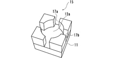
- FIG. 1 is a conceptual diagram of a microwell plate for forming a droplet array.
- FIG. 2 is a diagram illustrating an example of a peripheral portion of one well.
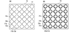
- FIG. 3 is an example of a top view of the microwell plate.
- FIG. 3A shows a microwell plate before droplets are formed, and
- FIG. 3B shows a microwell plate on which droplets are formed.
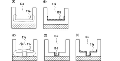
- FIG. 4 is a diagram for explaining the oil passage.
- FIG. 5 is a top view and a cross-sectional view of a well portion having a groove. 5A shows a top view and FIG. 5B shows a cross-sectional view.
- FIG. 6 is a conceptual diagram for explaining a method of manufacturing a droplet array.
- FIG. 1 is a conceptual diagram of a microwell plate for forming a droplet array.
- FIG. 2 is a diagram illustrating an example of a peripheral portion of one well.
- FIG. 3 is an example of a top view of the microwell plate
- FIG. 7 is a conceptual diagram showing how wells, flow paths, and droplets are formed after an oil component is added.
- FIG. 8 is a conceptual diagram showing a manufacturing process of a two-dimensional droplet array having a concentration gradient.
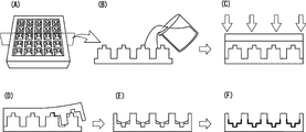
- FIG. 9 is a conceptual diagram showing an example of a method for manufacturing a microwell plate.
- FIG. 10 is a photograph replacing a drawing of the manufactured microwell plate.
- FIG. 10A shows an overall view of the manufactured microwell plate.
- FIG. 10B shows a partially enlarged view of the manufactured microwell plate.
- FIG. 11 is a photograph replacing a drawing showing the state of the microwell plate after addition of nomaldecane.
- FIG. 11 shows the state of two adjacent wells when nomaldecane is added.
- FIG. 11B shows the state of two adjacent wells 15 seconds after the addition of nomaldecane.
- FIG. 11C shows the state of two adjacent wells 30 seconds after the addition of nomaldecane.
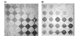
- FIG. 12 is a photograph replacing a drawing showing a microwell plate in which droplets are formed.
- FIG. 13 is a photograph replacing a drawing showing that a droplet having a concentration gradient was formed.
- FIG. 13A shows a state when nomaldecane is added, and
- FIG. 13B shows a state when a predetermined time has elapsed and droplets are formed.
- FIG. 14 is a photograph replacing a drawing showing the obtained droplet.
- FIG. 15 is a diagram showing the evaluation results of the obtained droplets.
- FIG. 16 is a graph instead of a drawing showing the ratio of droplets formed.
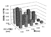
- FIG. 17 is a graph instead of a drawing showing the width and height of the groove of the first apparatus in the embodiment and the rate at which droplets are formed.
- FIG. 18 is a graph instead of a drawing showing the width and height of the groove of the second device in the embodiment and the rate at which droplets are formed.
- FIG. 19 is a drawing related to Example 9.
- FIG. 19A is a conceptual diagram showing an array in the embodiment.
- FIG. 19B is a diagram for explaining the well size.
- FIG. 19C is a conceptual diagram for explaining the state of the well.
- FIG. 19D is a table instead of a drawing showing the result of droplet generation by n-decane based on Ag and Ap.
- FIG. 19A is a conceptual diagram showing an array in the embodiment.
- FIG. 19B is a diagram for explaining the well size.
- FIG. 19C is a conceptual diagram for explaining the state of the well.
- FIG. 19D is a table instead of a drawing showing the result of droplet generation by
- FIG. 19E is a table instead of a drawing showing the result of droplet generation by n-hexane based on Ag and Ap.
- FIG. 19F is a table instead of a drawing showing the result of droplet generation by n-hexadecane based on Ag and Ap.
- FIG. 19G is a photograph replacing a drawing showing the state of the generated droplet.
- FIG. 19 (H) is a photograph replacing a drawing showing a connected droplet.
- FIG. 19I is a photograph replacing a drawing showing that n-hexane is linked in a short period of time.
- FIG. 19 (J) is a photograph replacing a drawing which shows that n-hexadecane has a lower droplet formation rate than other solvents.
- FIG. 19G is a photograph replacing a drawing showing the state of the generated droplet.
- FIG. 19 (H) is a photograph replacing a drawing showing a connected droplet.
- FIG. 19I is a photograph replacing a drawing
- FIG. 21 is a drawing related to Example 10.
- FIG. 21 is a drawing related to Example 11.
- FIG. FIG. 21A is a conceptual diagram showing a state in which fluorescent molecules Rhodamine B, Fluorescein, and n-decane are dropped onto a microwell plate having three reservoirs.
- FIG. 21B is a photograph replacing a drawing showing a microwell plate having three reservoirs.
- FIG. 21 (C) is a photograph replacing a drawing which shows a state in which a concentration gradient is generated by allowing to stand for 2 hours after dropping Rhodamine B and fluorescein.
- FIG. 21D is a photograph replacing a drawing which shows a state in which n-decane was dropped and droplets were generated after the state of FIG.
- FIG. 21E is a photograph replacing a drawing showing the concentration gradient of rhodamine B.
- FIG. 21F is a graph replaced with a drawing showing the concentration gradient of rhodamine B.
- FIG. 21 (G) is a photograph replacing a drawing showing a concentration gradient of fluorescein.
- FIG. 21 (H) is a graph replaced with a drawing showing the concentration gradient of fluorescein.
- FIG. 22 is a fluorescence micrograph in place of a drawing showing that sf9 cells are encapsulated in
- FIG. 1 is a conceptual diagram of a microwell plate for forming a droplet array.
- FIG. 2 is a diagram illustrating an example of a peripheral portion of one well.
- FIG. 3 is an example of a top view of the microwell plate.
- FIG. 3A shows a microwell plate before droplets are formed
- FIG. 3B shows a microwell plate on which droplets are formed.
- the microwell plate has a plurality of wells on a substrate.
- a microwell plate can accommodate various reagents and samples in a well, and is a kind of detection instrument used for reagent evaluation, biological evaluation, and pathological evaluation, for example.
- the microwell plate is already known as described in, for example, Japanese Patent No. 5848233, Japanese Patent No. 5642551, Japanese Patent No. 5592606, Japanese Patent No. 4996595, and Japanese Patent No. 4496962.
- An example of the size of the portion where the well exists in the microwell plate may be 3 mm to 50 cm on a side, 3 mm to 20 cm, or 5 mm to 10 cm.
- the size of this part may be square, rectangular, polygonal, circular or elliptical.
- the plate includes a substrate 11, a plurality of wells 13a, 13b, 13c, and 13d, and a plurality of flow paths 17a, 17b, and 17c.
- the material of the substrate is not particularly limited as long as it can form a well.
- a known material may be adopted as appropriate for the plate.
- plate materials are metals, resins and ceramics.
- metals are copper and aluminum.
- the resin are methacryl, acrylic, polyethylene, polypropylene, polystyrene, polyethylene terephthalate, vinyl chloride, polyamide, polycarbonate, hot melt, phenol, bakelite, melamine, polytetrafluoroethylene, epoxy, and mixed resins thereof.
- polypropylene, polystyrene, polycarbonate, polytetrafluoroethylene or polyethylene is preferable.
- a specific example of the material of the substrate is OSTEMER (registered trademark) crystal clear.
- the material of the substrate may be adjusted in consideration of the shape of the well and the channel, lipophilicity and hydrophilicity.
- the substrate may be molded integrally with the well and the flow path, or the substrate may be molded separately from the well and the flow path.
- a part of the surface of the substrate may be the bottom of a well, a channel, or a groove.
- the surface of the substrate preferably has water repellency. If the surface of the substrate has water repellency, an oil passage can be formed effectively and droplets can be formed efficiently.
- a substrate using a fluorine-based resin is a polytetrafluoroethylenic substrate.
- a water repellent layer may be provided on the surface of the substrate, and wells and flow paths may be formed on the substrate.
- the plurality of wells 13a, 13b, 13c, and 13d are wells formed in a two-dimensional array on the substrate.
- the number of wells may be appropriate depending on the measurement target.
- the number of specific wells is preferably 4 or more (2 ⁇ 2 or more) and 10,000 or less, may be 25 or more and 1000 or less, may be 36 or more and 1000 or less, and may be 100 or more and 400
- the number may be not more than 225, may be 225 or more and 400 or less, or may be 400 or more and 900 or less.
- Each well may have the same shape or a different shape.
- the well shape is different, for example, the well size may be different (for example, smaller) for each column. By doing so, the concentration gradient of the sample can be easily provided. Further, the well size may be different (for example, smaller) as the distance from a certain point increases.
- the shape seen from the top of the well is usually circular. On the other hand, it may be oval or polygonal.
- the area viewed from the upper surface of the well is 0.01 mm 2 or more and 10 mm 2 or less, 0.01 mm 2 or more and 4 mm 2 or less, 0.05 mm 2 or more and 2 mm 2 or less, 0.1 mm 2 or more and 1.5 mm 2 or less. Good.
- Examples of the depth of the well are 0.1 mm or more and 1 cm or less, 0.1 mm or more and 5 mm or less, 0.3 mm or more and 2 mm or less, 5 mm or more and 1 mm or less may be sufficient.
- the cross-sectional shape of the well may be a rectangle (or a rectangle having a groove portion), or may be a shape in which the width becomes narrower (or becomes wider) as it becomes deeper.
- the plurality of flow paths 17a, 17b, and 17c connect adjacent ones of the plurality of wells 13a, 13b, 13c, and 13d. Since there is no adjacent well at the end portion of the substrate 11, there is no need for a flow path, and there is provided a flow path that assumes that the arrayed well exists at the end portion of the substrate or at the end of the end portion. May be. In that case, the flow path existing at the end of the substrate may be one or plural.
- the flow path connects adjacent wells.
- This channel is a channel in which a liquid present in a certain well can move to an adjacent well when there is no obstacle in the channel.
- An example of the width of the flow path is that the oil component stays as the oil component passes through the flow path. Therefore, the shape of the flow path may be selected in consideration of physical force such as surface tension in the flow path.
- the shape of the channel is usually rectangular. However, the shape of the upper surface of the flow path may be reduced as it moves away from a certain point. Further, even if the shape of the flow path is rectangular, it may be designed so that the width of the flow path becomes smaller (or larger) as the distance from a certain well increases.
- the cross-sectional shape of the flow path is also usually rectangular (or a shape having a groove). On the other hand, the shape of the flow path may be a shape in which the width becomes narrower (or becomes wider) as it becomes deeper.
- the length of the channel is not less than 1000 times and not more than 1/2 of the width of the well (the maximum length of the well when it is assumed that the channel does not exist), and is not less than 1/500 and not more than 3 minutes. 1/200, 1/200 to 1/5, 1/100 to 1/8, or 1/50 to 1/10.
- the length of the flow path is 0.01 mm or more and 5 mm or less, 0.01 mm or more and 2 mm or less, or 0.01 mm or more and 0.5 mm or less. 05 mm or more and 0.5 mm or less may be sufficient, and 0.05 mm or more and 0.3 mm or less may be sufficient.
- the width of the channel is not less than 1/100 and not more than 1/2 of the well width (the maximum length of the well when it is assumed that the channel does not exist). It may be 1 or less, 1/20 or more and 1/5 or less, 1/15 or more and 1/8 or less, or 1/11 or more and 1/9 or less.
- An example of the width of the channel is one tenth of the width of the well.
- Specific examples of the width of the flow path are 0.01 mm to 10 mm, 0.01 mm to 0.5 mm, 0.03 mm to 0.2 mm, 0.05 mm to 0.00 mm. It may be 1 mm or less.
- the depth of the flow path may be the same as or different from the depth of the well.
- the upper surface of the channel may be the same height as the upper surface of the well.
- the flow path preferably includes an oil path.
- the bottom surface of the channel and the bottom surface of the well may be at the same position, or the bottom surface of the channel may be at a position lower than the bottom surface of the well.
- This plate may have grooves 23a, 23b, 23c, 23d.
- This groove is a groove that exists through a plurality of wells and a plurality of flow paths. This groove functions as an oil passage or part of an oil passage.
- the cross-sectional shape of the groove may be rectangular, semicircular, or inverted triangle.
- the oil passages 19a, 19b, 19c, 19d, and 19e are portions where oil components existing in the plurality of wells and the plurality of flow paths move.
- the oil passages exist in the wells and the flow passages, and may be portions where the physical properties are not different from the portions other than the oil passages, or may be portions where some physical properties are different.
- the oil path is preferably present in the lower part of the well and the flow path, and the oil component moves through the oil path.
- the microwell plate of the present invention has the above-described well and channel, and when the oil component is added in a state where the water component is present in the well and the channel, the oil component moves through the well and the channel. However, it has a shape and physical properties that can be propagated.
- the part where the oil component moves at this time is an oil passage. That is, the microwell plate of the present invention is a microwell plate for a new application. When an oil component is added in a state where a water component is present in the well and the channel, the oil component moves through the well and the channel. The microwell plate is used for propagating and forming droplets thereby.
- FIG. 4 is a diagram for explaining the oil passage.
- the oil passage 19a may be a well or a lower portion of the flow path.
- the oil passage 19a shown in FIG. 4 (A) has the same physical properties as the portions other than the oil passage.
- the oil passage may be a portion having physical properties different from those of other portions of the well or the flow passage.
- An example of the oil passage in this case is one in which different surface processing is applied to portions other than the oil passage and the oil passage.
- a portion other than the oil passage may be etched to make the surface roughness rough.
- only the oil passage portion may be mirror-finished.
- An oil passage may be formed by coating the oil passage portion. Any coating may be used as long as it can change the physical properties of the part other than the oil passage and can function as an oil passage.
- An example of the coating is a water repellent (hydrophobic agent).
- water repellents examples include waxes (eg, paraffin wax and natural wax), resins (eg, polypropylene resin, polyethylene resin, polyamide resin, and polyamine resin), fluororesins (eg, resins containing fluorine, poly Tetrafluoroethylene (PTFE), polyvinylidene fluoride (PVDF), polyhexafluoropropylene, tetrafluoroethylene-hexafluoropropylene copolymer (FEP) polytetrafluoroethylene, and polychlorotrifluoroethylene), and silicone resin (polymethyl) Hydrogen siloxane, and polydimethylsiloxane). These may be used alone or in combination.
- waxes eg, paraffin wax and natural wax
- resins eg, polypropylene resin, polyethylene resin, polyamide resin, and polyamine resin
- fluororesins eg, resins containing fluorine, poly Tetrafluoroethylene (PTFE), polyvinylid
- a specific example of the coating is CYTOP (types A to C) manufactured by Asahi Glass.
- the oil passage may be formed by depositing a metal on the oil passage portion.
- the oil passage formed in this way may form a layer called a water repellent layer or a hydrophobic layer. Then, when the oil component is added, the affinity to the oil component is higher than that of the water component, so that the oil component tends to stay in the flow path, and the oil component exists on the bottom of the well, and the liquid is contained in the well. Drops are easily formed.
- the oil passage 19c may be a groove present on the bottom surface of the well (and the bottom surface of the flow path). Since this groove functions as an oil passage, it is preferable that the groove is provided through the well bottom surface and the channel bottom surface.
- the groove is a portion provided below the bottom surface of the well and having a shape recessed from the bottom surface. In the example shown in FIG. 4C, only the groove portion may function as the oil passage, or the groove portion and the well bottom surface (and the flow path bottom surface) may function as the oil passage. Moreover, the whole groove part does not need to function as an oil path.
- the substrate surface may be a groove bottom surface, or the substrate surface may be exposed through the groove. When the substrate surface has water repellency, a good oil passage can be formed without coating the well, and droplets can be preferably produced. This eliminates the need for coating or the like, increasing productivity.
- the oil passage 19d is a groove present on the bottom surface of the well (and the flow path), and may have a surface with physical properties different from those of the well and the flow path surface.
- the surfaces having different physical properties are as described in the example of FIG. Even in this case, it is not necessary for the oil to move only through the groove portion, and it is sufficient that the oil contacts at least a part of the groove portion and moves.
- the oil passage 19d is provided not only in the groove existing on the bottom surface of the well (and flow path) but also in the well (and flow path), and has a physical property different from that of other portions. There may be. Also in this case, it is not necessary for oil to move while adhering to the entire oil passage, and it is sufficient that the oil contacts at least part of the oil passage and moves.
- FIG. 5 is a top view and a cross-sectional view of a well portion having a groove.
- 5A shows a top view and
- FIG. 5B shows a cross-sectional view.
- the depth D D of the groove examples of the depth of the well (at height) D W 25 over one of may be a 1 or less 1 or 2 minutes of the 20 minutes, 10 1 to 1/3, 1/6 to 1/4, or 1/5 may be used.
- Width W D of the groove may be the same as the width W W of the channel as shown in FIG. 5 (A), may be smaller than the width of the channel.
- the width of the groove may be not less than 1/3 and not more than 2/3 of the width of the flow path, and may be 1/2.
- oil components are added to the plate (well, channel or oil channel) in a state where water components exist in a plurality of wells and a plurality of channels, so that the oil component passes through the oil channel. And propagate through a plurality of wells and a plurality of flow paths.
- the plurality of flow paths 17a, 17b, and 17c are adjacent to each other by containing the oil components 23a and 23b in the plurality of flow paths 17a, 17b, and 17c in a state where the water component exists in the plurality of wells. To move to wells. In this way, droplets 21a, 21b, 21c, 21d and a droplet array are formed.
- This method is a method of obtaining a droplet array using the plate described above. This method is briefly described as follows. Add oil component with water component in well and flow path. As a result, the oil component propagates through the well and the oil passage of the flow path, while staying in the flow path. As the oil component stays in the flow path in this way, the water component in the well is isolated and droplets are formed.
- S means a step.
- FIG. 6 is a conceptual diagram for explaining a method of manufacturing a droplet array.
- FIG. 6A is a conceptual diagram showing the state of the plate before adding the water component. In this example, a plate having a groove below the well is used.
- the lower view of FIG. 6A is a schematic drawing of a top view and a cross-sectional view of a certain plate.
- Water component is added to the plurality of wells 13a, 13b, 13c, 13d and the flow paths 17a, 17b, 17c.
- the water component may be an aqueous solution or an alcohol solution containing a target sample, or may be a target sample dispersed or a target sample dissolved.
- the plate is configured such that a plurality of wells can flow liquid through the flow path. Therefore, for example, if a water component is added to a certain well, the water component is transmitted to a plurality of wells through the flow path.
- FIG. 6B is a conceptual diagram showing a state in which water components are distributed to the well and the flow path.
- the water component may be added in an amount contained in the entire well, or an amount obtained by dividing the amount that can be accommodated in the well and the flow path by dividing the amount of components added later (for example, oil component). It may be added.
- the amount of water component added to the whole well is added, the water component in the well rises and forms droplets after the oil component is added. For this reason, the water component may be added in an amount accommodated in the entire well.
- the oil component is added to any of the plurality of wells 13a, 13b, 13c, 13d and the flow paths 17a, 17b, 17c.
- the oil component may be added from any one well.
- an oil component may be added from any one flow path.
- an oil component addition part for adding an oil component to the plate may be provided, and the oil component may be added from the oil component addition part.
- the oil component preferably has a higher affinity for the well and the flow path than the water component.
- examples of the oil component are liquid alkanes having 4 to 20 carbon atoms, silicon oil, vegetable oil, essential oil, and ester (liquid).
- An example of the liquid alkane is a liquid alkane having 5 to 16 carbon atoms.
- examples of vegetable oils are corn oil, palm oil and palm shell oil.
- esters are myristyl myristate, myristyl palmitate, myristyl stearate, myristyl isostearate, myristyl oleate, myristyl behenate, myristyl erucate, cetyl myristate, cetyl palmitate, cetyl stearate, cetyl isostearate, olein Cetyl acid, cetyl behenate, cetyl elcaate, stearyl myristate, stearyl palmitate, stearyl stearate, stearyl isostearate, stearyl oleate, stearyl behenate, stearyl erucate, isostearyl myristate, isostearyl palmitate, stearin Isostearyl acid, Isostearyl isostearate, Isostearyl oleate, Isostearyl behenate, Isostearyl be
- FIG. 6 (C) is a schematic drawing of how oil components propagate.
- the oil component exists in the lower part of the well and propagates to the adjacent well through a groove connected to the flow path. Part of the oil component may propagate through the upper surface of the well. That is, since the oil component has a higher affinity (permeability) with the surface of the substrate than the water component, the oil component propagates through the substrate surface (including the well surface and the channel surface).
- the oil component is accommodated in the plurality of flow paths 17a, 17b, and 17c in a state where the water component exists in the plurality of wells 13a, 13b, 13c, and 13d.
- the water component is prevented from moving to the adjacent well, and droplets 21a, 21b, 21c, and 21d containing the water component are formed.
- FIG. 7 is a conceptual diagram showing how wells, flow paths, and droplets are formed after an oil component is added.
- the oil component passes through the flow path, a part of the oil component remains in the flow path.
- the water component can flow in the adjacent wells as shown in FIG.
- FIG. 7B when a sufficient amount of oil component remains in the flow path, as shown in FIG. 7B, the water component is divided in adjacent wells, and droplets are formed in each well.
- FIG. 7C is a conceptual diagram showing how droplets are formed.
- the manufacturing method of the above droplet array is as follows: Adding a water component to the plurality of wells 13a, 13b, 13c, 13d and the flow paths 17a, 17b, 17c; A step of adding an oil component to any of the plurality of wells 13a, 13b, 13c, 13d and the flow paths 17a, 17b, 17c after the water component is added; Including The oil component propagates through the continuous oil passages 19a, 19b, 19c, 19d, 19e existing in the plurality of wells 13a, 13b, 13c, 13d and the plurality of flow paths 17a, 17b, 17c, With the water component A present in the plurality of wells 13a, 13b, 13c, 13d, the oil components 23a, 23b are accommodated in the plurality of flow paths 17a, 17b, 17c, Preventing water components from moving to adjacent wells; Forming droplets 21a, 21b, 21c, 21d containing water components; It is a manufacturing method of a droplet array
- the target liquid is added to the plurality of wells 13a, 13b, 13c, after the step of adding the water component and before the step of adding the oil component. 13d and the process of adding to any of the some flow path 17a, 17b, 17c is further included.
- the step of adding the oil component is preferably performed as follows. That is, the oil component is added before the concentration of the target liquid becomes uniform in the plurality of wells 13a, 13b, 13c, and 13d. Then, in a state where the target liquid has a concentration gradient in the plurality of wells 13a, 13b, 13c, and 13d, the movement to the adjacent wells is hindered. In this way, a two-dimensional droplet array having a concentration gradient can be easily obtained.
- FIG. 8 is a conceptual diagram showing a manufacturing process of a two-dimensional droplet array having a concentration gradient.
- the first target liquid and the second target liquid are separately added to wells existing at opposite corners.
- the target liquid is not limited to one type but may be a plurality of types. In this case, each well has various concentrations and concentration ratios for a plurality of types of target liquids.
- the target liquid is a liquid containing the target sample. Examples of target samples include, but are not limited to, various reagents, markers, cells, microorganisms, genes, genetic materials, peptides, proteins, and dyes.
- a water component is added to the plurality of wells 13a, 13b, 13c, 13d and the flow paths 17a, 17b, 17c.
- the target liquid is added to any of the plurality of wells 13a, 13b, 13c, 13d and the plurality of flow paths 17a, 17b, 17c.
- the first target liquid and the second target liquid are separately added to the wells present at the opposite corners. Then, the first target liquid and the second target liquid propagate through the flow path and propagate to the adjacent wells.
- the target liquid After the target liquid is added and before the concentration of the target liquid becomes uniform in the plurality of wells 13a, 13b, 13c, 13d, the plurality of wells 13a, 13b, 13c, 13d and the flow paths 17a, 17b, Add oil component to any of 17c.
- the oil component propagates through the continuous oil passages 19a, 19b, 19c, 19d, and 19e existing in the plurality of wells 13a, 13b, 13c, and 13d and the plurality of flow paths 17a, 17b, and 17c.
- the oil components 23a and 23b are accommodated in the plurality of flow paths 17a, 17b, and 17c in a state where the water component exists in the plurality of wells 13a, 13b, 13c, and 13d.
- the water component is prevented from moving to the adjacent well, and droplets 21a, 21b, 21c, and 21d containing the water component are formed.
- FIG. 8B is a conceptual diagram showing that a plurality of droplets having a concentration gradient are formed for two types of target liquids.
- the target liquid cannot move to the adjacent wells in a state where the target liquid has a concentration gradient in the plurality of wells 13a, 13b, 13c, and 13d.
- a two-dimensional droplet array having a concentration gradient for the target liquid can be easily obtained.
- the microwell plate may be manufactured using a known method.
- a water repellent layer for example, a water repellent or a hydrophobic agent may be added to the well and the solvent evaporated.
- An example of a method for changing the surface roughness of a part of the substrate, the well and the flow path is to perform the sand blasting process with a part masked.
- a method for manufacturing a part having physically or scientifically different physical properties is already known.
- FIG. 9 is a conceptual diagram showing an example of a manufacturing method of a microwell plate.
- a template serving as a basis for the microwell plate was prepared (FIG. 9A).
- the mold was made of acrylic resin.
- the mold may be a metal.
- a groove is formed in the lower part of the well.
- a resin as a raw material for the substrate was injected into the mold (FIG. 9B).
- OSTECC was used.
- a side glass serving as a substrate was mounted on the resin, and then ultraviolet rays were irradiated to cure the OSTECC resin (FIG. 9C). Then, the resin on the mold was cured.
- the substrate was peeled off from the mold (FIG. 9D).
- the substrate was made of OSTECC resin, so it was flexible (flexible) and could be peeled off from the mold.
- the CYTOP solution was added so as to be in the fourth to sixth minutes of the well (FIG. 9E). With the CYTOP liquid added, the substrate was heated to 100 ° C. to solidify the CYTOP liquid (FIG. 9F). In this way, a water repellent layer (hydrophobic layer) was formed.
- the microwell plate produced in Example 1 was as follows.
- FIG. 10 is a photograph replacing the drawing of the manufactured microwell plate.
- FIG. 10A shows an overall view of the manufactured microwell plate.
- FIG. 10B shows a partially enlarged view of the manufactured microwell plate. As shown in FIG. 10A, a microwell plate was manufactured.
- a microwell plate was manufactured in the same manner as in Example 1 except that there was no groove.
- a microwell plate was manufactured in the same manner as in Example 1 except that the coating layer by CYTOP was not provided.
- a microwell plate was manufactured in the same manner as in Example 1 except that the coating layer by CYTOP was provided up to the upper surface of the well.
- FIG. 11 is a photograph replacing a drawing showing the state of the microwell plate after addition of nomaldecane.
- FIG. 11A shows the state of two adjacent wells when nomaldecane is added.
- FIG. 11B shows the state of two adjacent wells 15 seconds after the addition of nomaldecane.
- FIG. 11C shows the state of two adjacent wells 30 seconds after the addition of nomaldecane. As shown in FIG. 11C, it can be seen that droplets were formed in the wells.
- FIG. 12 is a photograph replacing a drawing showing a microwell plate in which droplets are formed.
- FIG. 13 is a photograph replacing a drawing showing that a droplet having a concentration gradient was formed.
- FIG. 13A shows a state when nomaldecane is added
- FIG. 13B shows a state when a predetermined time has elapsed and droplets are formed. As shown in FIG. 13B, it can be seen that by using this method, droplets were formed in a two-dimensional array with a concentration gradient.
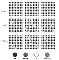
- a microwell plate having 9 ⁇ 9 (a total of 81) wells manufactured in Example 1 was prepared. After infiltrating the microwell plate with ethanol, the microwell plate was replaced with 0.5% indigo carmine aqueous solution (blue No. 2). Subsequently, approximately 10 ⁇ l of any of alkanes of normal hexane (Hexane: C 6 H 14 ), normal decane (Dekane: C 10 H 22 ), and normal hexadecane (Hexadecan: C 16 H 34 ) was dropped. For each alkane, the same kind of plate was used, and the state of droplet formation was investigated three times. The evaluation was as follows. Droplet: The well is filled with an independent aqueous solution (droplet). Connected droplet: An aqueous solution (droplet) is connected to an adjacent well or the outside. Empty: The well is filled with alkane. Damaged well (Broken well): The well is damaged.
- FIG. 14 is a photograph replacing a drawing showing the obtained droplet.
- FIG. 15 is a diagram showing the evaluation results of the obtained droplets. As shown in FIG. 15, the number of droplets was counted, and the ratio with the number of effective wells was taken. The result is shown in FIG. FIG. 16 is a graph instead of a drawing showing the ratio of droplets formed. As shown in FIG. 16, the ratio of droplets formed is 0.60 ⁇ 0.05 (Hexane), 0.76 ⁇ 0.13 (Decane), and 0.77 ⁇ 0.03 (respectively). Hexadecane).
- FIG. 17 shows the groove width and height of the first apparatus and the ratio of droplets formed.
- FIG. 18 shows the width and height of the groove of the second apparatus and the rate at which droplets are formed.
- a groove height (step) of 0 indicates an example in which a groove is not formed and a channel having a width indicated by a parameter value exists.
- 17 and 18 are graphs of the contents of Table 2.
- the x-axis indicates the groove (channel) width
- the y-axis indicates the groove height (step)
- the z-axis indicates the droplets. Indicates the rate of formation.
- the groove width is 0.02 mm or more and 0.08 mm or less, and the ratio of droplet formation is high.
- the droplets since the droplets are sufficiently formed even when the groove width is 0.02 mm, the droplets may be effectively formed even when the groove width is 0.02 or less. It can be said.
- the heights (steps) of the grooves were 0.2 mm and 0.4 mm. When the width of the film was 0.08 mm or less, droplets were stably formed.
- the groove heights were 0.2 mm and 0.4 mm, and both showed good droplet formation rates. Therefore, the height of the groove is not limited to 0.2 mm or 0.4 mm, and it is considered that droplets can be formed even when the height of the groove is 0.2 mm or less or 0.4 mm or more. It is done.
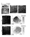
- FIG. 19 (D) shows the result of droplet generation by n-decane based on Ag and Ap.
- Ag 15
- droplets could be generated at a rate of 90% or more.
- FIGS. 19 (G) and 19 (H) show the generated droplet and the connected droplet, respectively.
- droplets could be generated using n-hexane and n-hexadecane. When N-hexane was used, it was found that the droplet formation rate was higher than when other solvents were used. This is probably because n-hexane has a lower viscosity than other solvents and can penetrate a wide range.
- n-hexane is a volatile solvent, it was found that it would be linked in a few seconds as shown in FIG. 19 (I). When n-hexadecane was used, a low droplet generation rate was observed compared to other solvents as shown in FIG. 19 (F).
- the droplets generated in the respective microwell plates are shown in FIGS. Indicates volume.
- FIGS. 21 (A) and 21 (B) Demonstration of Array with Concentration Gradient by Fluorescence Intensity Measurement
- a microwell plate having three reservoirs was fabricated.
- Fluorescent molecules Rhodamine B that emits red fluorescence, fluorescein that emits green fluorescence, and n-decane are dropped into these reservoirs.
- the mixture was allowed to stand for 2 hours to generate a concentration gradient (FIG. 21 (C)), and then n-decane was dropped to generate droplets (FIG. 21 (D)).
- Sf9 Cell encapsulation experiment A cell encapsulation experiment called Sf9 was conducted. First, sf9 cells stained with a substance that emits green fluorescence by an intracellular esterase reaction called calcein-AM were prepared. Subsequently, the microwell plate was filled with the medium containing the sf9 cells, and then droplets were generated by dropping n-decane. Observation with a fluorescence microscope confirmed that sf9 cells were encapsulated in the droplets as shown in FIG.
- the present invention can be used in the field of physics and chemistry equipment industry.
- the present invention can be used in the development of new drugs, biological experiments, and chemical experiments.
Landscapes
- Chemical & Material Sciences (AREA)
- Immunology (AREA)
- Microelectronics & Electronic Packaging (AREA)
- Health & Medical Sciences (AREA)
- Analytical Chemistry (AREA)
- Biochemistry (AREA)
- General Health & Medical Sciences (AREA)
- General Physics & Mathematics (AREA)
- Physics & Mathematics (AREA)
- Life Sciences & Earth Sciences (AREA)
- Pathology (AREA)
- Engineering & Computer Science (AREA)
- Computer Hardware Design (AREA)
- Organic Chemistry (AREA)
- Chemical Kinetics & Catalysis (AREA)
- Automatic Analysis And Handling Materials Therefor (AREA)
- Micromachines (AREA)
- Physical Or Chemical Processes And Apparatus (AREA)
- Apparatus Associated With Microorganisms And Enzymes (AREA)
Abstract
【課題】 液滴を簡易かつ低コストで製造でき,精密なポンプ及びピペット作業を行うことなく,濃度勾配を有する2次元液滴アレイを製造できる液滴アレイ形成用のマイクロウェルプレート及び液滴アレイの製造方法を提供する。 【解決手段】 マイクロウェル(井戸)を,流路を用いて連結した所定のマイクロウェルプレートを用い,水成分が存在する状態で試料を添加し,試料の濃度が一定になる前に,油成分を添加することにより,試料やサンプルが濃度勾配を生じた状態で,油が流路をふさぎ,これによって濃度勾配を有する2次元液滴アレイを製造できる。
Description
本発明は,液滴アレイ形成用のマイクロウェルプレート及び液滴アレイの製造方法に関する。
2次元にアレイ化された微小液滴は,生化学的アッセイ及び医療診断のハイスループット化や低コスト化に貢献することが期待されている。例えば,創薬分野におけるタンパク質の結晶化,新薬に対する細胞の感受性の評価,がんや感染症の診断に利用されるデジタルPCR,及び微生物・細胞培養など,微小液滴は,様々な用途に応用される可能性がある(下記非特許文献1~3)。
2次元液滴アレイ技術をさらに発展させるためには,精密な作業を要するポンプ・ピペット操作に依拠せずに,試薬やサンプルの濃度勾配をもつ液滴アレイを生成することが望まれる。
非特許文献1には,マイクロ流体デバイス内で液滴を生成し,アレイ化する技術が記載されている。
非特許文献2には,親水性表面がパターン化された基板を用いて,液滴アレイを生成する技術が記載されている。
非特許文献3には,スリップチップが記載されている。スリップチップは,対面する2つの基板上に設けられた溝をスライドさせて液滴を生成する技術である。
一般的に,2次元液滴アレイを生成するためには,ピペット操作が必要である(例えば,非特許文献3を参照)。特に,濃度勾配を有する液滴アレイを得ることは,上記のいずれの方法でも達成できず,ヒトによるピペット操作やポンプを用いた装置が必要である。
R. R. Pompano, et. al., Annu. Rev. Anal. Chem., 4, 59-81, 2011.
E. Ueda et. al., Adv. Mater., 25, 1234-1247, 2013.
H. Yan, et. al., Chinese J. Anal. Chem., 43, 10, 1520-1525, 2015
本発明は,液滴を簡易かつ低コストで製造できる液滴アレイ形成用のマイクロウェルプレート及び液滴アレイの製造方法を提供することを目的とする。
本発明は,精密なポンプ及びピペット作業を行うことなく,濃度勾配を有する2次元液滴アレイを製造できる,液滴アレイ形成用のマイクロウェルプレート及び液滴アレイの製造方法を提供することを目的とする。
本発明は,基本的には,マイクロウェル(井戸)を,流路を用いて連結した所定のマイクロウェルプレートを用いることで,水成分が存在する状態で,油を添加すれば,油がウェルと流路を伝搬し,流路をふさぐことで,容易に液滴を生成できるという知見に基づく。
本発明は,また,水成分が存在する状態で試料を添加し,試料の濃度が一定になる前に,油成分を添加することにより,試料が濃度勾配を生じた状態で,油が流路をふさぎ,これによって濃度勾配を有する2次元液滴アレイを製造できるという知見に基づく。
本発明は,第1に,液滴アレイ形成用のマイクロウェルプレートを提供する。このプレートは,基板11,複数のウェル13a,13b,13c,13d,及び複数の流路17a,17b,17cを含む。
複数のウェル13a,13b,13c,13dは,基板上に2次元アレイ状に形成された井戸状のものである。
液滴アレイ形成用のマイクロウェルプレート15は,複数のウェルを有し,複数のウェルのそれぞれに液滴を形成するためのプレートである。
複数の流路17a,17b,17cは,複数のウェル13a,13b,13c,13dのうち隣接するものを連結するものである。この流路は,流路に障害物がない場合,あるウェルに存在する液体が,隣接するウェルに移動することができるものである。
複数のウェル13a,13b,13c,13dは,基板上に2次元アレイ状に形成された井戸状のものである。
液滴アレイ形成用のマイクロウェルプレート15は,複数のウェルを有し,複数のウェルのそれぞれに液滴を形成するためのプレートである。
複数の流路17a,17b,17cは,複数のウェル13a,13b,13c,13dのうち隣接するものを連結するものである。この流路は,流路に障害物がない場合,あるウェルに存在する液体が,隣接するウェルに移動することができるものである。
本発明の液滴アレイ形成用のマイクロウェルプレートは,油路19a,19b,19c,19d,19eを有する。油路は,複数のウェル及び複数の流路に存在する油成分が移動する部分である。複数のウェル及び複数の流路に水成分が存在する状態で,油成分がプレート(ウェル,流路又は油路)に添加されることで,油成分が油路を経由し,複数のウェル及び複数の流路を伝搬する。一方,複数の流路17a,17b,17cは,水成分が複数のウェルに存在した状態で,複数の流路17a,17b,17cに油成分23a,23bを収容することで,水成分が隣接するウェルに移動することを防止する。このようにして,液滴21a,21b,21c,21d及び液滴アレイが形成される。
このプレートは,溝23a,23b,23c,23dを有していてもよい。この溝は,複数のウェル及び複数の流路を通じて存在する溝である。この溝は,油路又は油路の一部として機能する。
このプレートの油路は,複数のウェル及び複数の流路の下部壁面又は底面に設けられた親油性部分であってもよい。
次に,本発明の液滴アレイの製造方法について説明する。この方法は,先に説明したプレートを用いる。
複数のウェル13a,13b,13c,13d及び流路17a,17b,17cに水成分を添加する。
水成分が添加された後に,複数のウェル13a,13b,13c,13d及び流路17a,17b,17cのいずれかに油成分を添加する。
油成分が複数のウェル13a,13b,13c,13d及び複数の流路17a,17b,17cに存在する連続した油路19a,19b,19c,19d,19eを通して伝搬する。
すると,水成分が複数のウェル13a,13b,13c,13dに存在する状態で,複数の流路17a,17b,17cに油成分23a,23bが収容される。これにより,水成分が隣接するウェルに移動することが妨げられ,水成分を含む液滴21a,21b,21c,21dが形成される。
複数のウェル13a,13b,13c,13d及び流路17a,17b,17cに水成分を添加する。
水成分が添加された後に,複数のウェル13a,13b,13c,13d及び流路17a,17b,17cのいずれかに油成分を添加する。
油成分が複数のウェル13a,13b,13c,13d及び複数の流路17a,17b,17cに存在する連続した油路19a,19b,19c,19d,19eを通して伝搬する。
すると,水成分が複数のウェル13a,13b,13c,13dに存在する状態で,複数の流路17a,17b,17cに油成分23a,23bが収容される。これにより,水成分が隣接するウェルに移動することが妨げられ,水成分を含む液滴21a,21b,21c,21dが形成される。
上記とは別の本発明の液滴アレイの製造方法は,水成分を添加する工程の後であって,油成分を添加する工程の前に,対象液を複数のウェル13a,13b,13c,13d及び複数の流路17a,17b,17cのいずれかに添加する工程をさらに含む。
この場合,油成分を添加する工程は,以下のように行われることが好ましい。つまり,油成分が,対象液の濃度が複数のウェル13a,13b,13c,13dにおいて均一となる前に添加される。すると,対象液が複数のウェル13a,13b,13c,13dにおいて濃度勾配を有する状態で,隣接するウェルへの移動が妨げられることとなる。このようにすれば,濃度勾配を有する2次元液滴アレイを容易に得ることができることとなる。
本発明は,水成分を収容させた状態で油成分を添加するだけで,液滴を簡易かつ低コストで製造できる液滴アレイ形成用のマイクロウェルプレート及び液滴アレイの製造方法を提供できる。
本発明は,水成分を収容させた状態で対象液を添加し,対象液の濃度が均一になる前に,油成分を添加するだけで,精密なポンプ及びピペット作業を行うことなく,濃度勾配を有する2次元液滴アレイを製造できる,液滴アレイ形成用のマイクロウェルプレート及び液滴アレイの製造方法を提供できる。
以下,図面を用いて本発明を実施するための形態について説明する。本発明は,以下に説明する形態に限定されるものではなく,以下の形態から当業者が自明な範囲で適宜修正したものも含む。
図1は,液滴アレイ形成用のマイクロウェルプレートの概念図である。図2は,1つのウェルの周辺部分の例を示す図である。図3は,マイクロウェルプレートの上面図の例である。図3(A)は,液滴が形成される前のマイクロウェルプレートを示し,図3(B)は,液滴が形成されたマイクロウェルプレートを示す。図1に示されるように,マイクロウェルプレートは,基板上に複数のウェルを有するものである。マイクロウェルプレートは,ウェルに各種試薬や試料を収容でき,例えば,試薬評価,生物学的評価,及び病理学的評価に用いられる検出器具の一種である。マイクロウェルプレートは,例えば,特許第5848233号,特許第5642551号,特許第5592606号,特許第4965095号及び特許第4496962号に記載される通り,既に知られたものである。
マイクロウェルプレートのうちウェルが存在する部位の大きさの例は,一辺が3mm以上50cm以下であり,3mm以上20cm以下でもよいし,5mm以上10cm以下でもよい。この部位の大きさは正方形状であってもよいし,長方形状であっても,多角形状であっても,円形又は楕円形状であってもよい。
このプレートは,基板11,複数のウェル13a,13b,13c,13d,及び複数の流路17a,17b,17cを含む。基板の材質はウェルを形成できるものであれば,特に限定されない。プレートの材質は,公知のものを適宜採用すればよい。プレートの材料の例は,金属,樹脂及びセラミックスである。金属の例は,銅,及びアルミニウムである。樹脂の例は,メタクリル,アクリル,ポリエチレン,ポリプロピレン,ポリスチレン,ポリエチレンテフタレート,塩化ビニル,ポリアミド,ポリカーボネート,ホットメルト,フェノール,ベークライト,メラミン,ポリテトラフルオロエチレン,エポキシ及びこれらの混合樹脂である。これらの中では,ポリプロピレン,ポリスチレン,ポリカーボネート,ポリテトラフルオロエチレン又はポリエチレンが好ましい。具体的な基板の材料の例は,OSTEMER(登録商標)クリスタルクリアーである。基板の素材は,ウェルや流路の形状や,親油性及び親水性を考慮して調整すればよい。
基板はウェルや流路と一体に成形してもよいし,基板をウェルや流路と別に成形してもよい。基板の表面の一部が,ウェル,流路,又は溝の底部となっていてもよい。この場合,基板の表面は,撥水性を有するものが好ましい。基板の表面が撥水性を有すれば,効果的に油路を形成でき,しかも液滴を効率的に形成できる。そのような基板は,例えばフッ素系の樹脂を用いた基板の例は,ポリテトラフルオロエチレン性の基板である。また,基板の表面に撥水層を設け,その基板上にウェルや流路を形成してもよい。
複数のウェル13a,13b,13c,13dは,基板上に2次元アレイ状に形成された井戸状のものである。ウェルの数は,測定対象に応じて適切なものとすればよい。具体的なウェルの数は,4個以上(2×2個以上)1万個以下であることが好ましく,25個以上1000個以下でもよく,36個以上1000個以下でもよく,100個以上400個以下でもよく,225個以上400個以下でもよいし,400個以上900個以下でもよい。
各ウェルは,同じ形状でもよいし,異なる形状でもよい。ウェルの形状が異なる場合,例えば,列ごとにウェルの大きさが異なる(例えば小さくなる)ようにしてもよいこのようにすることで,試料の濃度勾配を容易につけることができる。また,ウェルの大きさは,ある一点から遠ざかるにつれてウェルの大きさが異なる(例えば小さくなる)ようにしてもよい。
各ウェルの形状は,対象となる試料や水成分の物性に応じて適切なものを選択すればよい。ウェルの上面から見た形状は,通常円形である。一方,楕円形や多角形であっても構わない。ウェルの上面からみた面積は,0.01mm2以上10mm2以下であり,0.01mm2以上4mm2以下でも,0.05mm2以上2mm2以下でも,0.1mm2以上1.5mm2以下でもよい。ウェルの深さ(ウェルの上面から底面までの高さ)の例は,0.1mm以上1cm以下であり,0.1mm以上5mm以下でもよいし,0.3mm以上2mm以下でもよいし,0.5mm以上1mm以下でもよい。ウェルの断面形状は,矩形(又は溝部分を有する矩形)であってもよいし,深くなるほど幅が狭くなる(又は広くなる)形状であってもよい。
複数の流路17a,17b,17cは,複数のウェル13a,13b,13c,13dのうち隣接するものを連結するものである。基板11の端部分には,隣接するウェルが存在しないので,流路が存在しなくてもよいし,アレイ状のウェルが基板の端部分又は端部分の先に存在すると仮定した流路が設けられてもよい。その場合,基板の端部に存在する流路は,1つでもよいし,複数であってもよい。
流路は,隣接するウェルを連結するものである。この流路は,流路に障害物がない場合,あるウェルに存在する液体が,隣接するウェルに移動することができるものである。流路の幅の例は,流路は,油成分が通るとともに油成分が滞在することとなる。そのため,流路における表面張力といった物理的な力を考慮して,流路の形状を選択すればよい。
流路の形状は,通常は矩形である。しかし,流路の上面形状は,ある点から遠ざかるについて小さくなってもよい。また,流路の形状が矩形であっても,あるウェルから遠ざかるにつれて,流路の幅が小さくなるように(又は大きくなるように)設計されていてもよい。流路の断面形状も通常は矩形(又は溝を有する形状)である。一方,流路の形状は,深くなるほど幅が狭くなる(又は広くなる)形状であってもよい。
流路の長さは,ウェルの幅(流路が存在しなかったと仮定した場合のウェルの最大長さ部分)の1000分の1以上2分の1以下であり,500分の1以上3分の1以下でもよいし,200分の1以上5分の1以下でもよいし,100分の1以上8分の1以下でもよいし,50分の1以上10分の1以下でもよい。具体的な,流路の長さは,0.01mm以上5mm以下であり,0.01mm以上2mm以下であってもよいし,0.01mm以上0.5mm以下であってもよいし,0.05mm以上0.5mm以下でもよいし,0.05mm以上0.3mm以下でもよい。
流路の幅は,ウェルの幅(流路が存在しなかったと仮定した場合のウェルの最大長さ部分)の100分の1以上2分の1以下であり,50分の1以上3分の1以下でもよいし,20分の1以上5分の1以下でもよいし,15分の1以上8分の1以下でもよいし,11分の1以上9分の1以下でもよい。流路の幅の例は,ウェルの幅の10分の1である。具体的な流路の幅の例は,0.01mm以上10mm以下であり,0.01mm以上0.5mm以下でもよいし,0.03mm以上0.2mm以下でもよいし,0.05mm以上0.1mm以下でもよい。
流路の深さは,ウェルの深さと同じでもよいし,異なってもよい。流路の深さがウェルの深さと同じ場合,流路の上面がウェルの上面と同じ高さになるようにしてもよい。一方,流路の深さがウェルの深さと異なる場合,流路の深さがウェルの深さより浅くても(高さが低くても),深さが深くても(高さが高くても)よい。いずれにせよ,流路は,油路を含むことが好ましい。流路の底面とウェルの底面が同じ位置にあってもよいし,流路の底面がウェルの底面より低い位置にあってもよい。流路の底面とウェルの底面が同じ位置の場合は,油成分がスムーズに流路を経由することとなる。一方,流路の底面がウェルの底面より低い位置にある場合,油成分が流路に留まりやすくなる。
このプレートは,溝23a,23b,23c,23dを有していてもよい。この溝は,複数のウェル及び複数の流路を通じて存在する溝である。この溝は,油路又は油路の一部として機能する。溝の断面形状は,矩形であってもよいし,半円状であってもよいし,逆三角形状であってもよい。
油路19a,19b,19c,19d,19eは,複数のウェル及び複数の流路に存在する油成分が移動する部分である。油路は,ウェル及び流路に存在しており,油路以外の部分と物性が何ら変わらない部分であってもよいし,何らかの物性が異なる部分であってもよい。油路は,ウェル及び流路の下部に存在し,油成分が油路を経由して移動するものが好ましい。本発明のマイクロウェルプレートは,上記したウェル及び流路を有しており,ウェル及び流路に水成分が存在する状態で,油成分を添加した場合に,ウェル及び流路を油成分が移動し,伝搬できるような形状及び物性を有している。この際の油成分が移動する部分が油路である。すなわち,本発明のマイクロウェルプレートは,新たな用途のマイクロウェルプレートであり,ウェル及び流路に水成分が存在する状態で,油成分を添加した場合に,ウェル及び流路を油成分が移動し,伝搬し,これにより液滴が形成されるという用途のマイクロウェルプレートである。
図4は,油路を説明するための図である。図4(A)に示されるように,油路19aは,ウェル又は流路の下部部分であってもよい。図4(A)に示される油路19aは,油路以外の部分と同じ物性を有している。
図4(B)に示されるように,油路は,ウェル又は流路のうち,他の部分と異なる物性を有する部位であってもよい。この場合の油路の例は,油路と油路以外の部分に異なる表面加工が施されているものである。例えば,油路以外の部分がエッチングされ,表面粗さが粗くなっていてもよい。また,油路部分のみに鏡面加工を施してもよい。油路部分にコーティングが施されることにより,油路が形成されてもよい。コーティングは,油路部分以外の部分と物性を変えることができ,油路として機能するようなものであれば,どのようなものを用いてもよい。コーティングの例は,撥水剤(疎水剤)である。撥水剤の例は,ワックス(例えば,パラフィン系ワックス及び天然ワックス),樹脂(例えば,ポリプロピレン樹脂,ポリエチレン樹脂,ポリアミド系樹脂,及びポリアミン系樹脂),フッ素樹脂(例えば,フッ素を含む樹脂,ポリテトラフルオロエチレン(PTFE),ポリフッ化ビニリデン(PVDF),ポリヘキサフルオロプロピレン,テトラフルオロエチレン-ヘキサフルオロプロピレン共重合体(FEP)ポリテトラフルオロエチレン,及びポリクロロトリフルオロエチレン),及びシリコーン樹脂(ポリメチル水素シロキサン,及びポリジメチルシロキサン)である。これらは単独で用いられてもよいし,複数が混合されて用いられてもよい。具体的なコーティングの例は,旭硝子社製のCYTOP(タイプA~C)である。油路部分に金属を蒸着させることで,油路を形成しても構わない。このようにして形成された油路は,撥水層又は疎水層ともよべる層を形成してもよい。すると,油成分が添加された際に,水成分に比べて油成分と親和性が高いので,流路に油成分が滞留しやすくなるとともに,ウェル底面に油成分が存在し,ウェル内で液滴が形成されやすくなる。
図4(C)に示されるように,油路19cは,ウェル底面(及び流路底面)に存在する溝であってもよい。この溝は,油路として機能するため,ウェル底面及び流路底面を通じて設けられるものが好ましい。溝は,ウェル底面の下方向に設けられ,底面より凹んだ形状を有する部分である。図4(C)に示される例では,溝部分のみが油路として機能してもよいし,溝部分とウェル底面(及び流路底面)が油路として機能してもよい。また,溝部分の全体が油路として機能しなくても構わない。この場合,基板表面が,溝底面であるか,基板表面が溝を介して露出していてもよい。基板表面が撥水性を有する場合,ウェルをコーティング等しなくても,良好な油路を形成でき,液滴を好ましく製造できる。すると,コーティング等を行う必要がなくなるため,生産性が高まる。
図4(D)に示されるように,油路19dは,ウェル(及び流路)底面に存在する溝であって,ウェル及び流路表面と異なる物性の表面を有するものであってもよい。この場合,異なる物性の表面は,図4(C)の例で説明したとおりである。この場合でも,油が,溝部分のみを経由して移動する必要はなく,油が,溝部分の少なくとも一部に接触し,移動すればよい。
図4(E)に示されるように,油路19dは,ウェル(及び流路)底面に存在する溝のみならずウェル(及び流路)に設けられ,他の部分と異なる物性を有する部位であってもよい。この場合も,油が油路全体に付着しつつ移動する必要はなく,油が油路の少なくとも一部に接触し,移動すればよい。
図5は,溝を有するウェル部分の上面図と断面図である。図5(A)は,上面図を示し,図5(B)は断面図を示す。
溝が存在する場合,溝の深さDDの例は,ウェルの深さ(高さ)DWの25分の1以上であり,20分の1以上2分の1以下でもよいし,10分の1以上3分の1以下でもよいし,6分の1以上4分の1以下でもよいし,5分の1でもよい。溝の幅WDは,図5(A)に示されるように流路の幅WWと同じでもよいし,流路の幅より小さくても構わない。溝の幅が流路の幅より小さい場合,溝の幅を流路の幅の3分の1以上3分の2以下とすればよく,2分の1でもよい。
このマイクロウェルプレートは,複数のウェル及び複数の流路に水成分が存在する状態で,油成分がプレート(ウェル,流路又は油路)に添加されることで,油成分が油路を経由し,複数のウェル及び複数の流路を伝搬する。一方,複数の流路17a,17b,17cは,水成分が複数のウェルに存在した状態で,複数の流路17a,17b,17cに油成分23a,23bを収容することで,水成分が隣接するウェルに移動することを防止する。このようにして,液滴21a,21b,21c,21dや液滴アレイが形成される。
次に,本発明の液滴アレイの製造方法について説明する。この方法は,先に説明したプレートを用いて,液滴アレイを得る方法である。この方法を簡単に説明すると,以下のとおりである。水成分をウェル及び流路に収容させた状態で,油成分を添加する。すると,油成分がウェル及び流路の油路を経由し伝搬する一方で,流路に滞在する。このように油成分が流路に滞在することで,ウェル内の水成分が孤立し,液滴が形成されるというものである。以下の説明でSはステップを意味する。
図6は,液滴アレイの製造方法を説明するための概念図である。図6(A)は,水成分を添加する前のプレートの様子を示す概念図である。この例は,ウェル下部に溝を有するプレートを用いている。図6(A)下図は,あるプレートの上面図と断面図を模式的に描画したものである。
複数のウェル13a,13b,13c,13d及び流路17a,17b,17cに水成分を添加する。水成分は,対象となる試料が含まれる水溶液やアルコール溶液であってもよいし,対象試料が分散しているものや対象試料が溶解しているものであってもよい。このプレートは,複数のウェルが流路を通じて液体を流すことができるようにされている。このため,例えば,あるウェルに水成分を添加すれば,流路を通じて,複数のウェルに水成分が伝わることとなる。図6(B)は,水成分がウェル及び流路にいきわたった様子を示す概念図である。水成分は,ウェル全体に収容される量を添加してもよいし,ウェル及び流路が収容できる量から後に添加される成分(例えば,油成分)の量を除した分を除した量を添加してもよい。水成分が,ウェル全体に収容される量を添加された場合,油成分を添加した後に,ウェル内の水成分が盛り上がり液滴を形成する。このため,水成分が,ウェル全体に収容される量を添加されても構わない。
水成分が添加された後に,複数のウェル13a,13b,13c,13d及び流路17a,17b,17cのいずれかに油成分を添加する。油成分は,いずれか一つのウェルから添加されてもよい。また,油成分は,いずれか一つの流路から添加されてもよい。さらに,プレートに油成分を添加するための油成分添加部を設け,油成分添加部から油成分を添加してもよい。
油成分は,水成分と完全に混合しないものであれば,公知の油成分や有機溶媒を適宜用いることができる。油成分は,水成分に比べて,ウェル及び流路に親和性の高いものが好ましい。水成分が水を主成分として含む場合,油成分の例は,炭素数4以上20以下の液体アルカン,シリコーオンオイル,植物油,精油,及びエステル(液状)である。液体アルカンの例は,炭素数が5以上16以下の液体アルカンである。植物油の例は,コーン油,パーム油及びパーム殻油である。エステルの例は,ミリスチン酸ミリスチル,パルミチン酸ミリスチル,ステアリン酸ミリスチル,イソステアリン酸ミリスチル,オレイン酸ミリスチル,ベヘン酸ミリスチル,エルカ酸ミリスチル,ミリスチン酸セチル,パルミチン酸セチル,ステアリン酸セチル,イソステアリン酸セチル,オレイン酸セチル,ベヘン酸セチル,エルカ酸セチル,ミリスチン酸ステアリル,パルミチン酸ステアリル,ステアリン酸ステアリル,イソステアリン酸ステアリル,オレイン酸ステアリル,ベヘン酸ステアリル,エルカ酸ステアリル,ミリスチン酸イソステアリル,パルミチン酸イソステアリル,ステアリン酸イソステアリル,イソステアリン酸イソステアリル,オレイン酸イソステアリル,ベヘン酸イソステアリル,オレイン酸イソステアリル,ミリスチン酸オレイル,パルミチン酸オレイル,ステアリン酸オレイル,イソステアリン酸オレイル,オレイン酸オレイル,ベヘン酸オレイル,エルカ酸オレイル,ミリスチン酸ベヘニル,パルミチン酸ベヘニル,ステアリン酸ベヘニル,イソステアリン酸ベヘニル,オレイン酸ベヘニル,ベヘン酸ベヘニル,エルカ酸ベヘニル,ミリスチン酸エルシル,パルミチン酸エルシル,ステアリン酸エルシル,イソステアリン酸エルシル,オレイン酸エルシル,ベヘン酸エルシル,及びエルカ酸エルシルである。これらは1種で用いてもよいし,2種以上を混合して用いてもよい。
油成分が複数のウェル13a,13b,13c,13d及び複数の流路17a,17b,17cに存在する連続した油路19a,19b,19c,19d,19eを通して伝搬する。図6(C)は,油成分が伝搬する様子を模式的に描画したものである。油成分は,ウェル下部に存在し,流路とつながる溝を通して,隣接するウェルに伝搬する。なお,油成分の一部は,ウェルの上面を通して,伝搬してもよい。つまり,油成分は,基板の表面との親和性(浸透性)が水成分に比べて高いので,基板表面(ウェル表面や流路表面を含む)を通じて,伝搬することとなる。すると,水成分が複数のウェル13a,13b,13c,13dに存在する状態で,複数の流路17a,17b,17cに油成分が収容される。これにより,水成分が隣接するウェルに移動することが妨げられ,水成分を含む液滴21a,21b,21c,21dが形成される。
図7は,油成分が添加された後のウェルと流路及び液滴が形成される様子を示す概念図である。油成分が流路を通過すると,油成分の一部が流路に留まる。油成分が流路に留まる量が少ないと図7に示されるように,隣接するウェルにおいて水成分は流動できる。一方,十分な量の油成分が流路に留まる場合,図7(B)に示されるように,隣接するウェルにおいて水成分が分断され,各ウェルに液滴が形成される。図7(C)は,液滴が形成された様子を示す概念図である。
上記の液滴アレイの製造方法は,
複数のウェル13a,13b,13c,13d及び流路17a,17b,17cに水成分を添加する工程と,
水成分が添加された後に,複数のウェル13a,13b,13c,13d及び流路17a,17b,17cのいずれかに油成分を添加する工程と,
を含み,
油成分が複数のウェル13a,13b,13c,13d及び複数の流路17a,17b,17cに存在する連続した油路19a,19b,19c,19d,19eを通して伝搬し,
水成分Aが複数のウェル13a,13b,13c,13dに存在する状態で,複数の流路17a,17b,17cに油成分23a,23bが収容され,
水成分が隣接するウェルに移動することが妨げられ,
水成分を含む液滴21a,21b,21c,21dを形成する,
液滴アレイの製造方法である。
複数のウェル13a,13b,13c,13d及び流路17a,17b,17cに水成分を添加する工程と,
水成分が添加された後に,複数のウェル13a,13b,13c,13d及び流路17a,17b,17cのいずれかに油成分を添加する工程と,
を含み,
油成分が複数のウェル13a,13b,13c,13d及び複数の流路17a,17b,17cに存在する連続した油路19a,19b,19c,19d,19eを通して伝搬し,
水成分Aが複数のウェル13a,13b,13c,13dに存在する状態で,複数の流路17a,17b,17cに油成分23a,23bが収容され,
水成分が隣接するウェルに移動することが妨げられ,
水成分を含む液滴21a,21b,21c,21dを形成する,
液滴アレイの製造方法である。
上記とは別の本発明の液滴アレイの製造方法は,水成分を添加する工程の後であって,油成分を添加する工程の前に,対象液を複数のウェル13a,13b,13c,13d及び複数の流路17a,17b,17cのいずれかに添加する工程をさらに含む。
この場合,油成分を添加する工程は,以下のように行われることが好ましい。つまり,油成分が,対象液の濃度が複数のウェル13a,13b,13c,13dにおいて均一となる前に添加される。すると,対象液が複数のウェル13a,13b,13c,13dにおいて濃度勾配を有する状態で,隣接するウェルへの移動が妨げられることとなる。このようにすれば,濃度勾配を有する2次元液滴アレイを容易に得ることができることとなる。
図8は,濃度勾配を有する2次元液滴アレイの製造工程を示す概念図である。この例では,対向する角に存在するウェルに,第1の対象液と第2の対象液が別々に添加されるものである。このように,対象液は1種類ではなく,複数種類であってもよい。この場合,各ウェルは,複数種類の対象液について,様々な濃度及び濃度割合を有した状態となる。対象液は,対象試料を含む液体である。対象試料の例は,各種試薬,マーカー,細胞,微生物,遺伝子,遺伝物質,ペプチド,タンパク質,及び色素であるが,これらに限定されない。
複数のウェル13a,13b,13c,13d及び流路17a,17b,17cに水成分を添加する。
次に,水成分が添加された後に,対象液を複数のウェル13a,13b,13c,13d及び複数の流路17a,17b,17cのいずれかに添加する。図8(A)に示される例では,対向する角に存在するウェルに,第1の対象液と第2の対象液が別々に添加される。すると,第1の対象液と第2の対象液が流路を伝って,隣接するウェルへと伝搬する。
対象液が添加された後であって,対象液の濃度が複数のウェル13a,13b,13c,13dにおいて均一となる前に,複数のウェル13a,13b,13c,13d及び流路17a,17b,17cのいずれかに油成分を添加する。
油成分が複数のウェル13a,13b,13c,13d及び複数の流路17a,17b,17cに存在する連続した油路19a,19b,19c,19d,19eを通して伝搬する。
すると,水成分が複数のウェル13a,13b,13c,13dに存在する状態で,複数の流路17a,17b,17cに油成分23a,23bが収容される。これにより,水成分が隣接するウェルに移動することが妨げられ,水成分を含む液滴21a,21b,21c,21dが形成される。
次に,水成分が添加された後に,対象液を複数のウェル13a,13b,13c,13d及び複数の流路17a,17b,17cのいずれかに添加する。図8(A)に示される例では,対向する角に存在するウェルに,第1の対象液と第2の対象液が別々に添加される。すると,第1の対象液と第2の対象液が流路を伝って,隣接するウェルへと伝搬する。
対象液が添加された後であって,対象液の濃度が複数のウェル13a,13b,13c,13dにおいて均一となる前に,複数のウェル13a,13b,13c,13d及び流路17a,17b,17cのいずれかに油成分を添加する。
油成分が複数のウェル13a,13b,13c,13d及び複数の流路17a,17b,17cに存在する連続した油路19a,19b,19c,19d,19eを通して伝搬する。
すると,水成分が複数のウェル13a,13b,13c,13dに存在する状態で,複数の流路17a,17b,17cに油成分23a,23bが収容される。これにより,水成分が隣接するウェルに移動することが妨げられ,水成分を含む液滴21a,21b,21c,21dが形成される。
図8(B)は,2種類の対象液について濃度勾配を有した液滴が複数形成されたことを示す概念図である。このように,対象液が複数のウェル13a,13b,13c,13dにおいて濃度勾配を有する状態で,対象液が隣接するウェルへ移動できなくなる。このようにすれば,対象液について濃度勾配を有する2次元液滴アレイを容易に得ることができることとなる。
次にマイクロウェルプレートの製造方法について説明する。上記のとおりマイクロウェルプレート自体はすでに知られているので,すでに知られた方法を用いて,マイクロウェルプレートを製造すればよい。また,撥水層(疎水層)を形成するためには,例えば,撥水剤や疎水剤をウェルに添加し,溶媒を蒸発させればよい。基板,ウェル及び流路の一部の表面粗さを変化させる方法の例は,一部分をマスキングした状態でサンドブラスト処理を行うものである。このように,物理的又は科学的に物性が異なる部位を製造する方法も既に知られている。
マイクロウェルプレートの製造
図9は,マイクロウェルプレートの製造方法の例を示す概念図である。
この例では,まず,マイクロウェルプレートのもととなる鋳型を用意した(図9(A))。鋳型はアクリル樹脂で製造した。鋳型は,金属であってもよい。また,この例は,ウェル下部に溝が形成されるものであった。
鋳型に,基板の原料となる樹脂を注入した(図9(B))。図9(B)の例では,OSTECCを用いた。
この例では,基板となるサイドグラスを樹脂上に搭載した後,OSTECC樹脂を硬化させるため,紫外線を照射した(図9(C))。すると,鋳型上の樹脂が硬化した。
その後,鋳型から基板をはがした(図9(D))。基板は,OSTECC樹脂で形成されているため可撓性があり(フレキシブルであり),鋳型からはがすことができた。
次に,物性の異なる部分を形成するため,CYTOP液をウェルの4分目~6分目程度になるように添加した(図9(E))。
CYTOP液が添加された状態で,基板を100℃に加熱し,CYTOP液を固化させた(図9(F))。このようにして,撥水層(疎水層)を形成した。
図9は,マイクロウェルプレートの製造方法の例を示す概念図である。
この例では,まず,マイクロウェルプレートのもととなる鋳型を用意した(図9(A))。鋳型はアクリル樹脂で製造した。鋳型は,金属であってもよい。また,この例は,ウェル下部に溝が形成されるものであった。
鋳型に,基板の原料となる樹脂を注入した(図9(B))。図9(B)の例では,OSTECCを用いた。
この例では,基板となるサイドグラスを樹脂上に搭載した後,OSTECC樹脂を硬化させるため,紫外線を照射した(図9(C))。すると,鋳型上の樹脂が硬化した。
その後,鋳型から基板をはがした(図9(D))。基板は,OSTECC樹脂で形成されているため可撓性があり(フレキシブルであり),鋳型からはがすことができた。
次に,物性の異なる部分を形成するため,CYTOP液をウェルの4分目~6分目程度になるように添加した(図9(E))。
CYTOP液が添加された状態で,基板を100℃に加熱し,CYTOP液を固化させた(図9(F))。このようにして,撥水層(疎水層)を形成した。
実施例1で製造したマイクロウェルプレートは,以下の通りであった。

図10は,製造されたマイクロウェルプレートの図面に替る写真である。図10(A)は,製造されたマイクロウェルプレートの全体図を示す。図10(B)は,製造されたマイクロウェルプレートの部分拡大図を示す。図10(A)に示されるように,マイクロウェルプレートが製造された。
溝がない以外は,実施例1と同様にしてマイクロウェルプレートを製造した。
CYTOPによるコート層を設けない以外は,実施例1と同様にしてマイクロウェルプレートを製造した。
CYTOPによるコート層をウェルの上面まで設けた以外は,実施例1と同様にしてマイクロウェルプレートを製造した。
液滴アレイの製造
実施例1で製造したマイクロウェルプレートに水成分としてエタノールを添加し,ウェル及び流路を充てんした。その後,油成分としてノマルデカンを添加した。図11は,ノマルデカンを添加した後の,マイクロウェルプレートの様子を示す図面に替る写真である。図11(A)は,ノマルデカンを添加した際の隣接する2つのウェルの様子を示す。図11(B)は,ノマルデカンを添加し15秒後の隣接する2つのウェルの様子を示す。図11(C)は,ノマルデカンを添加し30秒後の隣接する2つのウェルの様子を示す。図11(C)に示されるように,ウェル内に液滴が形成されたことがわかる。図12は,液滴が形成されたマイクロウェルプレートを示す図面に替る写真である。
実施例1で製造したマイクロウェルプレートに水成分としてエタノールを添加し,ウェル及び流路を充てんした。その後,油成分としてノマルデカンを添加した。図11は,ノマルデカンを添加した後の,マイクロウェルプレートの様子を示す図面に替る写真である。図11(A)は,ノマルデカンを添加した際の隣接する2つのウェルの様子を示す。図11(B)は,ノマルデカンを添加し15秒後の隣接する2つのウェルの様子を示す。図11(C)は,ノマルデカンを添加し30秒後の隣接する2つのウェルの様子を示す。図11(C)に示されるように,ウェル内に液滴が形成されたことがわかる。図12は,液滴が形成されたマイクロウェルプレートを示す図面に替る写真である。
実施例2~4で製造したマイクロウェルプレートについても液滴が製造されるか検討した。その結果,溝を有しており,部分的に撥水層が形成されたものが最もよく液滴を形成した。一方,溝を有さず,しかも撥水層を有しないものでは,液滴が形成された数が最も少なかった。
濃度勾配を有する2次元液滴アレイの製造
実施例1で製造したマイクロウェルプレートの対角から赤の食物色素及び青の食物色素を含む溶液を対象液として添加し,2つの対象液の濃度が均一となる前に,油成分としてノマルデカンを添加した。その様子を図13に示す。
図13は,濃度勾配を有する液滴を形成したことを示す図面に替る写真である。図13(A)は,ノマルデカンを添加した際の様子を示し,図13(B)は所定時間が経過し,液滴が形成された際の様子を示す。図13(B)に示されるように,この方法を用いることで,濃度勾配を有する状態で,液滴が2次元アレイ状に形成されたことがわかる。
実施例1で製造したマイクロウェルプレートの対角から赤の食物色素及び青の食物色素を含む溶液を対象液として添加し,2つの対象液の濃度が均一となる前に,油成分としてノマルデカンを添加した。その様子を図13に示す。
図13は,濃度勾配を有する液滴を形成したことを示す図面に替る写真である。図13(A)は,ノマルデカンを添加した際の様子を示し,図13(B)は所定時間が経過し,液滴が形成された際の様子を示す。図13(B)に示されるように,この方法を用いることで,濃度勾配を有する状態で,液滴が2次元アレイ状に形成されたことがわかる。
実施例1で製造した9×9(合計81個)のウェルを有するマイクロウェルプレートを用意した。マイクロウェルプレートにエタノールを浸透させた後,0.5%のインディゴカルミン水溶液(青色2号)で置き換えた。続いて,ノマルヘキサン(Hexane:C6H14),ノマルデカン(Decane:C10H22),及びノマルヘキサデカン(Hexadecane:C16H34)のアルカンいずれかをおよそ10μl滴下した。それぞれのアルカンに対し,同一種類のプレートを用い,3回ずつ液滴の生成状況を調査した。評価は,以下のようにした。
液滴(droplet):ウェルに独立した水溶液(液滴)が満たされている。
連結液滴(Connected droplet):隣のウェル又は外部に水溶液(液滴)が接続している。
空(Empty):ウェルにアルカンが満たされている。
損傷ウェル(Broken well):ウェルに損傷がある。
液滴(droplet):ウェルに独立した水溶液(液滴)が満たされている。
連結液滴(Connected droplet):隣のウェル又は外部に水溶液(液滴)が接続している。
空(Empty):ウェルにアルカンが満たされている。
損傷ウェル(Broken well):ウェルに損傷がある。
図14は,得られた液滴を示す図面に替る写真である。図15は,得られた液滴の評価結果を示す図である。図15に示されるように,液滴数をカウントし,有効なウェルの数との比を取った。その結果を図16に示す。図16は,液滴が形成された割合を示す図面に替るグラフである。図16に示されるように,液滴が形成される割合は,それぞれ,0.60±0.05(Hexane),0.76±0.13(Decane),及び0.77±0.03(Hexadecane)であった。
溝(下部流路)の幅と高さ(ステップ)とを様々なものとした以外は実施例1と同様にして9×9のマイクロウェルプレートを2種類用意した。用意したマイクロウェルプレートの溝の幅と高さは,以下の表におけるパラメータ値(mm)として表されている。液滴が形成される割合(液滴数/井戸(ウェル)数)を以下の表に示す。また,最初の装置の溝の幅と高さと,液滴が形成される割合を図17に示す。2番目の装置の溝の幅と高さと,液滴が形成される割合を図18に示す。溝の高さ(ステップ)が0とは,溝が形成されず,パラメータ値で示される幅の流路が存在する例を示す。図17及び図18は,表2の内容をグラフ化したものであり,x軸は溝(チャネル)の幅を示し,y軸は溝の高さ(ステップ)を示し,z軸は液滴が形成される割合を示す。
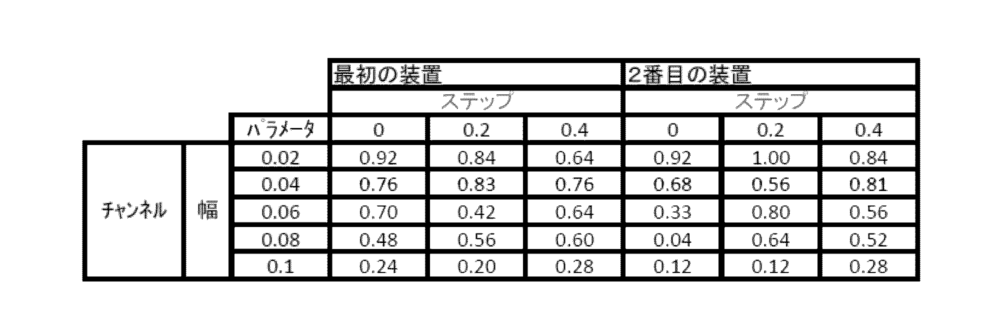
上記の結果から,溝の幅は,0.02mm以上0.08mm以下で液滴が形成される割合が高いことがわかる。また,溝の幅が0.02mmでも十分に液滴が形成されているから,溝の幅が,0.02以下の場合であっても,液滴が効果的に形成される可能性があるといえる。また,溝がないものと,溝があるものとの間で,液滴形成において有意差は見いだされなかったものの,溝の高さ(ステップ)が0.2mm及び0.4mmであって,溝の幅が0.08mm以下の場合は,安定的に液滴が形成されていた。このため,溝の高さが0.2mm以上0.4mm以下であって,溝の幅が0.08mm以下の場合に高い割合で液滴が形成されることがわかる。なお,上記の例は,溝の高さを0.2mm及び0.4mmのものであり,いずれも良好な液滴形成率を示した。このため,溝の高さは,0.2mmや0.4mmに限定されず,溝の高さが0.2mm以下や,0.4mm以上の場合であっても,液滴を形成できると考えられる。
ウェルアレイの寸法及び有機溶媒の種類に関する液滴生成率の調査
図19(A)に示されるように4×19のウェルを有するアレイを用意した.アレイの一端には溶媒導入用のリザーバを製作した.図19(B)のように,ウェルの直径(D),幅(W),高さ(H),ステップ高さ(S)からAg=D/WとAp=S/Wを定義し,これらの値をもとに液滴生成率を調べた.DとHを500 μmに固定し,WとSの値を変更しAgとApの値を変更した.溶媒導入後ウェル中の残存水溶液は生成液滴,連結液滴と液滴無の3状態に分類でき,液滴生成率は,生成液滴数を有効なウェル数で割った値と定義した.観察のため,水溶液として青色の0.5%インディゴカルミン水溶液を使用した.溶媒として,水と混ざり合わないn-デカン,n-ヘキサンとn-ヘキサデカンを使用した.
図19(A)に示されるように4×19のウェルを有するアレイを用意した.アレイの一端には溶媒導入用のリザーバを製作した.図19(B)のように,ウェルの直径(D),幅(W),高さ(H),ステップ高さ(S)からAg=D/WとAp=S/Wを定義し,これらの値をもとに液滴生成率を調べた.DとHを500 μmに固定し,WとSの値を変更しAgとApの値を変更した.溶媒導入後ウェル中の残存水溶液は生成液滴,連結液滴と液滴無の3状態に分類でき,液滴生成率は,生成液滴数を有効なウェル数で割った値と定義した.観察のため,水溶液として青色の0.5%インディゴカルミン水溶液を使用した.溶媒として,水と混ざり合わないn-デカン,n-ヘキサンとn-ヘキサデカンを使用した.
図19(D)は,AgとApに基づくn-デカンによる液滴生成の結果を表している.Ag=15の時,9割以上の割合で液滴生成を行うことができた.図19(G)と図19(H)はそれぞれ,生成液滴と連結液滴を示している.図19(E)と図19(F)のように,n-ヘキサンとn-ヘキサデカンを用いて液滴生成を行うことができた.N-ヘキサンを用いた場合,他の溶媒を用いた場合よりも高い液滴生成率を示すことが分かった.これは,n-ヘキサンが他の溶媒に比べ粘性が低く広範囲に浸透できることが理由として考えられる.しかしながら,n-ヘキサンは揮発性溶媒であるため,図19(I)のように数秒で連結してしまうことが分かった.n-ヘキサデカンを用いた場合,図19(F)のように他の溶媒に比べ低い液滴生成率が観察された.
マイクロウェルプレート中の生成液滴の体積評価
2種類のパラメータ(Ag=10, Ap=0,下部流路無し)と(Ag=15, Ap=4,下部流路有り)のマイクロウェルプレートを用い,図20(A)と図20(B)のようにn-デカンにより液滴を生成した.水溶液中に赤色蛍光を示すローダミンB(RhodamineB)を含ませ,蛍光による観察を可能とした.生成液滴をn-デカン中に浸し,共焦点顕微鏡により3次元画像を取得し,1列(column)おきに液滴の体積を概算した.
2種類のパラメータ(Ag=10, Ap=0,下部流路無し)と(Ag=15, Ap=4,下部流路有り)のマイクロウェルプレートを用い,図20(A)と図20(B)のようにn-デカンにより液滴を生成した.水溶液中に赤色蛍光を示すローダミンB(RhodamineB)を含ませ,蛍光による観察を可能とした.生成液滴をn-デカン中に浸し,共焦点顕微鏡により3次元画像を取得し,1列(column)おきに液滴の体積を概算した.
図20(C)と図20(D)は,(Ag=10, Ap=0)と(Ag=15, Ap=4)の場合であり,それぞれのマイクロウェルプレート中に生成された液滴の体積を示している.(Ag=10, Ap=0)では列数が増加するごとに液滴の体積が微増しているのに対し,(Ag=15, Ap=4)ではそのような傾向は確認されなかった.この結果から,下部流路を設けることで列ごとの体積変化を抑制できることが分かった.
蛍光強度測定による濃度勾配を有するアレイの実証
図21(A)及び図21(B)のように,3つのリザーバを有するマイクロウェルプレートを製作した.これらのリザーバにはそれぞれ,赤色蛍光を発する蛍光分子ローダミンB(RhodamineB)と緑色蛍光を発するフルオレセイン(Fluorescein),及びn-デカンが滴下される.ローダミンBとフルオレセイン滴下後2時間静置し濃度勾配を生成した(図21(C))後,n-デカンが滴下され液滴が生成された(図21(D)).
図21(A)及び図21(B)のように,3つのリザーバを有するマイクロウェルプレートを製作した.これらのリザーバにはそれぞれ,赤色蛍光を発する蛍光分子ローダミンB(RhodamineB)と緑色蛍光を発するフルオレセイン(Fluorescein),及びn-デカンが滴下される.ローダミンBとフルオレセイン滴下後2時間静置し濃度勾配を生成した(図21(C))後,n-デカンが滴下され液滴が生成された(図21(D)).
図21(E)~図21(H)のように,ローダミンBとフルオレセインの濃度勾配を液滴中に含有することに成功した.
細胞封入実験
Sf9と呼ばれる細胞の封入実験を行った.初めに,カルセイン(Calcein)-AMという細胞内のエステラーゼ反応により緑色蛍光を発する物質で染色されたsf9細胞を用意した.続いてマイクロウェルプレート中にこのsf9細胞を含む培地を満たし,続いてn-デカンの滴下により液滴生成を行った.蛍光顕微鏡での観察を行うと,図22のように液滴中にsf9細胞が封入されていることが確認された.
Sf9と呼ばれる細胞の封入実験を行った.初めに,カルセイン(Calcein)-AMという細胞内のエステラーゼ反応により緑色蛍光を発する物質で染色されたsf9細胞を用意した.続いてマイクロウェルプレート中にこのsf9細胞を含む培地を満たし,続いてn-デカンの滴下により液滴生成を行った.蛍光顕微鏡での観察を行うと,図22のように液滴中にsf9細胞が封入されていることが確認された.
本発明は,理化学機器産業の分野で利用されうる。本発明は,新薬の開発や,生物学的な実験,化学的な実験において利用されうる。
11 基板; 13a,13b,13c,13d ウェル;
15 マイクロウェルプレート;17a,17b,17c 流路;
19a,19b,19c,19d,19e 油路;
21a,21b,21c,21d 液滴;
23a,23b,23c,23d 溝
15 マイクロウェルプレート;17a,17b,17c 流路;
19a,19b,19c,19d,19e 油路;
21a,21b,21c,21d 液滴;
23a,23b,23c,23d 溝
Claims (5)
- 基板(11)と,
前記基板上に設けられ,2次元アレイ状に形成された複数のウェル(13a,13b,13c,13d)を含む,
液滴アレイ形成用のマイクロウェルプレート(15)であって,
前記複数のウェル(13a,13b,13c,13d)のうち隣接するものを連結する複数の流路(17a,17b,17c)をさらに有し,
前記複数のウェル(13a,13b,13c,13d)及び前記複数の流路(17a,17b,17c)は,前記複数のウェル及び前記複数の流路に水成分が存在する状態で,油成分が添加されることで,前記油成分が前記複数のウェル及び前記複数の流路を伝搬する,連続した油路(19a,19b,19c,19d,19e)を有し,
前記複数の流路(17a,17b,17c)は,前記水成分が前記複数のウェルに存在した状態で,前記複数の流路(17a,17b,17c)に油成分(23a,23b)を収容することで,前記水成分が隣接するウェルに移動することを防止し,液滴(21a,21b,21c,21d)が形成される,
液滴アレイ形成用のマイクロウェルプレート(15)。 - 請求項1に記載の液滴アレイ形成用のマイクロウェルプレート(15)であって,
前記複数のウェル(13a,13b,13c,13d)及び前記複数の流路(17a,17b,17c)を通じて存在する溝(23a,23b,23c,23d)をさらに有する,
液滴アレイ形成用のマイクロウェルプレート(15)。 - 請求項1に記載の液滴アレイ形成用のマイクロウェルプレート(15)であって,
前記油路(19a,19b,19c,19d)は,前記複数のウェル(13a,13b,13c,13d)及び前記複数の流路(17a,17b,17c)の下部壁面又は底面に設けられた親油性部分である,
液滴アレイ形成用のマイクロウェルプレート(15)。 - 基板(11)と,
前記基板上に設けられ,2次元アレイ状に形成された複数のウェル(13a,13b,13c,13d)と,
前記複数のウェルのうち隣接するものを連結する複数の流路(17a,17b,17c)と,を含む,
マイクロウェルプレート(15)を用い,
前記複数のウェル(13a,13b,13c,13d)及び前記流路(17a,17b,17c)に水成分を添加する工程と,
前記水成分が添加された後に,前記複数のウェル(13a,13b,13c,13d)及び前記流路(17a,17b,17c)のいずれかに油成分を添加する工程と,
を含み,
前記油成分が前記複数のウェル(13a,13b,13c,13d)及び前記複数の流路(17a,17b,17c)に存在する連続した油路(19a,19b,19c,19d,19e)を通して伝搬し,
前記水成分が前記複数のウェル(13a,13b,13c,13d)に存在する状態で,前記複数の流路(17a,17b,17c)に前記油成分(23a,23b)が収容され,
前記水成分が隣接するウェルに移動することが妨げられ,
前記水成分を含む液滴(21a,21b,21c,21d)を形成する,
液滴アレイの製造方法。 - 請求項4に記載の液滴アレイの製造方法であって,
前記水成分を添加した後であって,前記油成分を添加する前に,対象液を前記複数のウェル(13a,13b,13c,13d)及び前記複数の流路(17a,17b,17c)のいずれかに添加する工程をさらに含み,
前記油成分が,前記対象液の濃度が前記複数のウェル(13a,13b,13c,13d)において均一となる前に添加されることで,前記対象液が前記複数のウェル(13a,13b,13c,13d)において濃度勾配を有する状態で,隣接するウェルへの移動が妨げられる,
液滴アレイの製造方法。
Priority Applications (1)
| Application Number | Priority Date | Filing Date | Title |
|---|---|---|---|
| JP2018525211A JPWO2018003856A1 (ja) | 2016-06-28 | 2017-06-28 | 液滴アレイ形成用のマイクロウェルプレート及び液滴アレイの製造方法 |
Applications Claiming Priority (2)
| Application Number | Priority Date | Filing Date | Title |
|---|---|---|---|
| JP2016-127183 | 2016-06-28 | ||
| JP2016127183 | 2016-06-28 |
Publications (1)
| Publication Number | Publication Date |
|---|---|
| WO2018003856A1 true WO2018003856A1 (ja) | 2018-01-04 |
Family
ID=60785431
Family Applications (1)
| Application Number | Title | Priority Date | Filing Date |
|---|---|---|---|
| PCT/JP2017/023752 Ceased WO2018003856A1 (ja) | 2016-06-28 | 2017-06-28 | 液滴アレイ形成用のマイクロウェルプレート及び液滴アレイの製造方法 |
Country Status (2)
| Country | Link |
|---|---|
| JP (1) | JPWO2018003856A1 (ja) |
| WO (1) | WO2018003856A1 (ja) |
Cited By (5)
| Publication number | Priority date | Publication date | Assignee | Title |
|---|---|---|---|---|
| WO2019208795A1 (ja) * | 2018-04-26 | 2019-10-31 | 国立大学法人東京大学 | マイクロリアクタチップ上での濃度勾配形成方法およびマイクロリアクタチップ |
| WO2021040021A1 (ja) * | 2019-08-30 | 2021-03-04 | 公立大学法人大阪 | 被検出物質の検出方法および被検出物質の検出システム |
| CN112881729A (zh) * | 2021-01-15 | 2021-06-01 | 中山大学 | 一种药物浓度梯度产生和加样装置及其应用 |
| CN116615526A (zh) * | 2020-10-06 | 2023-08-18 | 国立研究开发法人理化学研究所 | 靶标物质的检测方法、流体装置及试剂盒 |
| CN120679619A (zh) * | 2025-06-13 | 2025-09-23 | 重庆大学 | 一种微流控药敏芯片及其应用 |
Citations (5)
| Publication number | Priority date | Publication date | Assignee | Title |
|---|---|---|---|---|
| JP2005523710A (ja) * | 2002-04-24 | 2005-08-11 | サーフェイス ロジックス,インコーポレイティド | 白血球遊走のモニター装置及び方法 |
| JP2006181407A (ja) * | 2004-12-27 | 2006-07-13 | Pentax Corp | Pdms製シート |
| JP2007017155A (ja) * | 2005-07-05 | 2007-01-25 | National Institute Of Advanced Industrial & Technology | マイクロ流路ビーズアレイデバイス及びその作製方法 |
| JP2010110262A (ja) * | 2008-11-06 | 2010-05-20 | Hitachi Maxell Ltd | ウェルプレートを用いた核酸増幅法 |
| JP2014503832A (ja) * | 2011-01-28 | 2014-02-13 | シロアム バイオサイエンシズ,インコーポレイテッド | 微小流体アッセイ装置および方法 |
-
2017
- 2017-06-28 WO PCT/JP2017/023752 patent/WO2018003856A1/ja not_active Ceased
- 2017-06-28 JP JP2018525211A patent/JPWO2018003856A1/ja active Pending
Patent Citations (5)
| Publication number | Priority date | Publication date | Assignee | Title |
|---|---|---|---|---|
| JP2005523710A (ja) * | 2002-04-24 | 2005-08-11 | サーフェイス ロジックス,インコーポレイティド | 白血球遊走のモニター装置及び方法 |
| JP2006181407A (ja) * | 2004-12-27 | 2006-07-13 | Pentax Corp | Pdms製シート |
| JP2007017155A (ja) * | 2005-07-05 | 2007-01-25 | National Institute Of Advanced Industrial & Technology | マイクロ流路ビーズアレイデバイス及びその作製方法 |
| JP2010110262A (ja) * | 2008-11-06 | 2010-05-20 | Hitachi Maxell Ltd | ウェルプレートを用いた核酸増幅法 |
| JP2014503832A (ja) * | 2011-01-28 | 2014-02-13 | シロアム バイオサイエンシズ,インコーポレイテッド | 微小流体アッセイ装置および方法 |
Cited By (6)
| Publication number | Priority date | Publication date | Assignee | Title |
|---|---|---|---|---|
| WO2019208795A1 (ja) * | 2018-04-26 | 2019-10-31 | 国立大学法人東京大学 | マイクロリアクタチップ上での濃度勾配形成方法およびマイクロリアクタチップ |
| WO2021040021A1 (ja) * | 2019-08-30 | 2021-03-04 | 公立大学法人大阪 | 被検出物質の検出方法および被検出物質の検出システム |
| CN116615526A (zh) * | 2020-10-06 | 2023-08-18 | 国立研究开发法人理化学研究所 | 靶标物质的检测方法、流体装置及试剂盒 |
| US12523606B2 (en) | 2020-10-06 | 2026-01-13 | Riken | Method for detecting target substance, fluid device, and kit |
| CN112881729A (zh) * | 2021-01-15 | 2021-06-01 | 中山大学 | 一种药物浓度梯度产生和加样装置及其应用 |
| CN120679619A (zh) * | 2025-06-13 | 2025-09-23 | 重庆大学 | 一种微流控药敏芯片及其应用 |
Also Published As
| Publication number | Publication date |
|---|---|
| JPWO2018003856A1 (ja) | 2019-05-23 |
Similar Documents
| Publication | Publication Date | Title |
|---|---|---|
| CN114272964B (zh) | 样品体积的自数字化 | |
| WO2018003856A1 (ja) | 液滴アレイ形成用のマイクロウェルプレート及び液滴アレイの製造方法 | |
| US9056289B2 (en) | Droplet creation techniques | |
| JP4987885B2 (ja) | 小滴中で反応を行うための装置及びその使用方法 | |
| Shang et al. | Emerging droplet microfluidics | |
| CN106423314B (zh) | 用于液滴产生和/或流体操纵的系统和方法 | |
| US9095852B2 (en) | Multilayer high density microwells | |
| JP2004500578A (ja) | ミクロ流体装置内の流体キャリオーバーの減少方法 | |
| US20180196059A1 (en) | Method for detecting biological substance | |
| Khor et al. | Interfacial tension driven open droplet microfluidics | |
| Yasuga et al. | Self-generation of two-dimensional droplet array using oil–water immiscibility and replacement | |
| Francz et al. | Subnanoliter precision piezo pipette for single-cell isolation and droplet printing | |
| Pompano et al. | Control of initiation, rate, and routing of spontaneous capillary-driven flow of liquid droplets through microfluidic channels on SlipChip | |
| Gupta et al. | Pinning and depinning dynamics of an evaporating sessile droplet containing mono-and bidispersed colloidal particles on a nonheated/heated hydrophobic substrate | |
| Li et al. | Dead-end filling of SlipChip evaluated theoretically and experimentally as a function of the surface chemistry and the gap size between the plates for lubricated and dry SlipChips | |
| KR102342742B1 (ko) | 무동력 미소액적 혼합 및 유동제어 기법 | |
| Zagnoni et al. | Droplet microfluidics for high-throughput analysis of cells and particles | |
| Fouillet et al. | EWOD digital microfluidics for Lab on a Chip | |
| Zhou et al. | Wetting behavior of surface nanodroplets regulated by periodic nanostructured surfaces | |
| Walsh et al. | Formation of droplet interface bilayers in a Teflon tube | |
| Murano et al. | Development of 3D-structured tilt capillary valve for lab-on-a-disc devices | |
| EP3662988B1 (en) | Method for optimization of droplet formation rate using dripping/jetting to co-flow transition of vacuum-driven microfluidic flow-focusing device with rectangular microchannels | |
| Wang et al. | An open-pattern droplet-in-oil planar array for single cell analysis based on sequential inkjet printing technology | |
| JP2022175985A (ja) | マイクロ流路チップにおいてエマルジョンを生成する方法及び装置 | |
| Tenorio-Barajas et al. | Microdroplet formation in microfluidic channels by multiphase flow simulation |
Legal Events
| Date | Code | Title | Description |
|---|---|---|---|
| 121 | Ep: the epo has been informed by wipo that ep was designated in this application |
Ref document number: 17820210 Country of ref document: EP Kind code of ref document: A1 |
|
| ENP | Entry into the national phase |
Ref document number: 2018525211 Country of ref document: JP Kind code of ref document: A |
|
| NENP | Non-entry into the national phase |
Ref country code: DE |
|
| 122 | Ep: pct application non-entry in european phase |
Ref document number: 17820210 Country of ref document: EP Kind code of ref document: A1 |