WO2018003757A1 - 信号処理装置、信号処理方法、カメラシステム、ビデオシステムおよびサーバ - Google Patents
信号処理装置、信号処理方法、カメラシステム、ビデオシステムおよびサーバ Download PDFInfo
- Publication number
- WO2018003757A1 WO2018003757A1 PCT/JP2017/023452 JP2017023452W WO2018003757A1 WO 2018003757 A1 WO2018003757 A1 WO 2018003757A1 JP 2017023452 W JP2017023452 W JP 2017023452W WO 2018003757 A1 WO2018003757 A1 WO 2018003757A1
- Authority
- WO
- WIPO (PCT)
- Prior art keywords
- video signal
- signal
- hdr
- unit
- processing
- Prior art date
Links
- 238000012545 processing Methods 0.000 title claims abstract description 399
- 238000003672 processing method Methods 0.000 title claims description 5
- 238000007906 compression Methods 0.000 claims abstract description 253
- 230000006835 compression Effects 0.000 claims abstract description 223
- 238000000034 method Methods 0.000 claims description 147
- 238000006243 chemical reaction Methods 0.000 claims description 97
- 238000003384 imaging method Methods 0.000 claims description 17
- 238000004148 unit process Methods 0.000 abstract description 2
- 230000005540 biological transmission Effects 0.000 description 49
- 238000012546 transfer Methods 0.000 description 34
- 238000012937 correction Methods 0.000 description 31
- 238000004891 communication Methods 0.000 description 26
- 239000011159 matrix material Substances 0.000 description 22
- 238000005516 engineering process Methods 0.000 description 19
- 238000010586 diagram Methods 0.000 description 18
- 210000003127 knee Anatomy 0.000 description 15
- 239000000463 material Substances 0.000 description 12
- 238000012544 monitoring process Methods 0.000 description 12
- 238000004519 manufacturing process Methods 0.000 description 11
- 238000007781 pre-processing Methods 0.000 description 6
- 239000000284 extract Substances 0.000 description 5
- MYPYJXKWCTUITO-UHFFFAOYSA-N vancomycin Natural products O1C(C(=C2)Cl)=CC=C2C(O)C(C(NC(C2=CC(O)=CC(O)=C2C=2C(O)=CC=C3C=2)C(O)=O)=O)NC(=O)C3NC(=O)C2NC(=O)C(CC(N)=O)NC(=O)C(NC(=O)C(CC(C)C)NC)C(O)C(C=C3Cl)=CC=C3OC3=CC2=CC1=C3OC1OC(CO)C(O)C(O)C1OC1CC(C)(N)C(O)C(C)O1 MYPYJXKWCTUITO-UHFFFAOYSA-N 0.000 description 5
- 238000000605 extraction Methods 0.000 description 3
- 230000006837 decompression Effects 0.000 description 2
- 230000003287 optical effect Effects 0.000 description 2
- 230000002730 additional effect Effects 0.000 description 1
- 230000015556 catabolic process Effects 0.000 description 1
- 230000007423 decrease Effects 0.000 description 1
- 238000006731 degradation reaction Methods 0.000 description 1
- 230000000694 effects Effects 0.000 description 1
- 230000002349 favourable effect Effects 0.000 description 1
- 238000012986 modification Methods 0.000 description 1
- 230000004048 modification Effects 0.000 description 1
- 239000013307 optical fiber Substances 0.000 description 1
- 230000001172 regenerating effect Effects 0.000 description 1
- 230000009466 transformation Effects 0.000 description 1
Images


Classifications
-
- G—PHYSICS
- G06—COMPUTING; CALCULATING OR COUNTING
- G06T—IMAGE DATA PROCESSING OR GENERATION, IN GENERAL
- G06T1/00—General purpose image data processing
- G06T1/20—Processor architectures; Processor configuration, e.g. pipelining
-
- H—ELECTRICITY
- H04—ELECTRIC COMMUNICATION TECHNIQUE
- H04N—PICTORIAL COMMUNICATION, e.g. TELEVISION
- H04N23/00—Cameras or camera modules comprising electronic image sensors; Control thereof
- H04N23/70—Circuitry for compensating brightness variation in the scene
- H04N23/741—Circuitry for compensating brightness variation in the scene by increasing the dynamic range of the image compared to the dynamic range of the electronic image sensors
-
- H—ELECTRICITY
- H04—ELECTRIC COMMUNICATION TECHNIQUE
- H04N—PICTORIAL COMMUNICATION, e.g. TELEVISION
- H04N19/00—Methods or arrangements for coding, decoding, compressing or decompressing digital video signals
- H04N19/46—Embedding additional information in the video signal during the compression process
-
- H—ELECTRICITY
- H04—ELECTRIC COMMUNICATION TECHNIQUE
- H04N—PICTORIAL COMMUNICATION, e.g. TELEVISION
- H04N19/00—Methods or arrangements for coding, decoding, compressing or decompressing digital video signals
- H04N19/90—Methods or arrangements for coding, decoding, compressing or decompressing digital video signals using coding techniques not provided for in groups H04N19/10-H04N19/85, e.g. fractals
- H04N19/98—Adaptive-dynamic-range coding [ADRC]
-
- H—ELECTRICITY
- H04—ELECTRIC COMMUNICATION TECHNIQUE
- H04N—PICTORIAL COMMUNICATION, e.g. TELEVISION
- H04N21/00—Selective content distribution, e.g. interactive television or video on demand [VOD]
- H04N21/20—Servers specifically adapted for the distribution of content, e.g. VOD servers; Operations thereof
- H04N21/23—Processing of content or additional data; Elementary server operations; Server middleware
- H04N21/234—Processing of video elementary streams, e.g. splicing of video streams or manipulating encoded video stream scene graphs
- H04N21/2343—Processing of video elementary streams, e.g. splicing of video streams or manipulating encoded video stream scene graphs involving reformatting operations of video signals for distribution or compliance with end-user requests or end-user device requirements
-
- H—ELECTRICITY
- H04—ELECTRIC COMMUNICATION TECHNIQUE
- H04N—PICTORIAL COMMUNICATION, e.g. TELEVISION
- H04N21/00—Selective content distribution, e.g. interactive television or video on demand [VOD]
- H04N21/40—Client devices specifically adapted for the reception of or interaction with content, e.g. set-top-box [STB]; Operations thereof
- H04N21/43—Processing of content or additional data, e.g. demultiplexing additional data from a digital video stream; Elementary client operations, e.g. monitoring of home network or synchronising decoder's clock; Client middleware
- H04N21/44—Processing of video elementary streams, e.g. splicing a video clip retrieved from local storage with an incoming video stream or rendering scenes according to encoded video stream scene graphs
- H04N21/4402—Processing of video elementary streams, e.g. splicing a video clip retrieved from local storage with an incoming video stream or rendering scenes according to encoded video stream scene graphs involving reformatting operations of video signals for household redistribution, storage or real-time display
-
- H—ELECTRICITY
- H04—ELECTRIC COMMUNICATION TECHNIQUE
- H04N—PICTORIAL COMMUNICATION, e.g. TELEVISION
- H04N23/00—Cameras or camera modules comprising electronic image sensors; Control thereof
- H04N23/50—Constructional details
-
- H—ELECTRICITY
- H04—ELECTRIC COMMUNICATION TECHNIQUE
- H04N—PICTORIAL COMMUNICATION, e.g. TELEVISION
- H04N23/00—Cameras or camera modules comprising electronic image sensors; Control thereof
- H04N23/60—Control of cameras or camera modules
- H04N23/66—Remote control of cameras or camera parts, e.g. by remote control devices
- H04N23/663—Remote control of cameras or camera parts, e.g. by remote control devices for controlling interchangeable camera parts based on electronic image sensor signals
-
- H—ELECTRICITY
- H04—ELECTRIC COMMUNICATION TECHNIQUE
- H04N—PICTORIAL COMMUNICATION, e.g. TELEVISION
- H04N23/00—Cameras or camera modules comprising electronic image sensors; Control thereof
- H04N23/60—Control of cameras or camera modules
- H04N23/67—Focus control based on electronic image sensor signals
-
- H—ELECTRICITY
- H04—ELECTRIC COMMUNICATION TECHNIQUE
- H04N—PICTORIAL COMMUNICATION, e.g. TELEVISION
- H04N23/00—Cameras or camera modules comprising electronic image sensors; Control thereof
- H04N23/80—Camera processing pipelines; Components thereof
-
- H—ELECTRICITY
- H04—ELECTRIC COMMUNICATION TECHNIQUE
- H04N—PICTORIAL COMMUNICATION, e.g. TELEVISION
- H04N5/00—Details of television systems
- H04N5/14—Picture signal circuitry for video frequency region
- H04N5/20—Circuitry for controlling amplitude response
- H04N5/202—Gamma control
-
- H—ELECTRICITY
- H04—ELECTRIC COMMUNICATION TECHNIQUE
- H04N—PICTORIAL COMMUNICATION, e.g. TELEVISION
- H04N25/00—Circuitry of solid-state image sensors [SSIS]; Control thereof
- H04N25/60—Noise processing, e.g. detecting, correcting, reducing or removing noise
- H04N25/61—Noise processing, e.g. detecting, correcting, reducing or removing noise the noise originating only from the lens unit, e.g. flare, shading, vignetting or "cos4"
- H04N25/615—Noise processing, e.g. detecting, correcting, reducing or removing noise the noise originating only from the lens unit, e.g. flare, shading, vignetting or "cos4" involving a transfer function modelling the optical system, e.g. optical transfer function [OTF], phase transfer function [PhTF] or modulation transfer function [MTF]
- H04N25/6153—Noise processing, e.g. detecting, correcting, reducing or removing noise the noise originating only from the lens unit, e.g. flare, shading, vignetting or "cos4" involving a transfer function modelling the optical system, e.g. optical transfer function [OTF], phase transfer function [PhTF] or modulation transfer function [MTF] for colour signals
Definitions
- the present technology relates to a signal processing device, a signal processing method, a camera system, a video system, and a server, and more particularly to a signal processing device that handles a high dynamic range video signal.
- HDR high dynamic range
- OETF Opto-Electrical Transfer Function
- EOTF Electro-Optical Transfer Function
- OOTF Opto-Optical Transfer Function
- OETF and EOTF are basically canceled by the outgoing OETF and the receiving EOTF. Therefore, even if the HDR video signal interface is different and the OETF and EOTF are different, the influence on the video actually displayed on the monitor can be reduced.
- OOTF is a video correction characteristic when displayed on a monitor, if the signal interface is different and the OOTF is different, even if the same video signal (camera video) is displayed, the video displayed on the monitor has a difference in appearance. appear.
- An object of the present technology is to enable favorable handling of HDR video signals of a plurality of signal interfaces.
- the concept of this technology is A processing unit for processing a linear high dynamic range video signal to obtain a high dynamic range video signal subjected to gradation compression processing,
- the processing unit is in a signal processing device capable of performing gradation compression processing of a plurality of signal interfaces.
- the processing unit processes a linear HDR (high dynamic range) video signal and obtains a high dynamic range video signal subjected to gradation compression processing.
- a linear HDR video signal is obtained by the imaging unit.
- the processing unit can perform gradation compression processing of a plurality of signal interfaces.
- the processing unit can perform gradation compression processing of a plurality of signal interfaces. Therefore, it is possible to obtain an HDR video signal that has been subjected to gradation conversion processing of a plurality of signal interfaces, and to improve usability.
- the processing unit further performs at least processing for adding a system gamma characteristic of the reference signal interface when performing gradation compression processing of a signal interface other than the reference signal interface. May be.
- the video is an HDR video signal subjected to gradation compression processing of the reference signal interface.
- the same signal processing is performed as in the case of monitoring with the interface compatible monitor (reference monitor). Therefore, even when outputting an HDR video signal subjected to gradation compression processing of a signal interface other than the reference signal interface, it is possible to perform camera adjustment (video adjustment) based on the video of the reference monitor. It becomes.
- a processing unit for processing a linear high dynamic range video signal to obtain a high dynamic range video signal subjected to gradation compression processing of a reference signal interface A signal conversion unit that converts a high dynamic range video signal subjected to gradation compression processing of the reference signal interface into a high dynamic range video signal subjected to gradation compression processing of a signal interface other than the reference signal interface With The signal converter is The high dynamic range video signal subjected to the gradation compression processing of the reference signal interface has at least the gradation expansion processing corresponding to the gradation compression processing of the reference signal interface and the system gamma characteristics of the reference signal interface. The signal processing apparatus performs each of the processing to be added and the gradation compression processing of the other signal interface.
- an HDR video signal obtained by processing a linear HDR (high dynamic range) video signal and performing gradation compression processing of the reference signal interface is obtained by the processing unit.
- a linear HDR video signal is obtained by the imaging unit.
- the signal conversion unit converts the HDR video signal subjected to the gradation compression processing of the reference signal interface into a high dynamic range video signal subjected to the gradation compression processing of a signal interface other than the reference signal interface.
- the signal conversion unit performs processing for converting the high dynamic range video signal that has been subjected to gradation compression processing of the reference signal interface into a state that has been subjected to gradation compression processing of another signal interface. That is, in this signal converter, the HDR video signal that has been subjected to the gradation compression processing of the reference signal interface, the gradation expansion processing corresponding to the gradation compression processing of the reference signal interface, and the gradation compression of the other signal interface Processing is performed. Further, in this signal conversion unit, processing for adding at least the system gamma characteristic of the reference signal interface to the HDR video signal subjected to the gradation compression processing of the reference signal interface is performed.
- the signal conversion unit performs processing for adding at least the system gamma characteristic of the reference signal interface to the HDR video signal subjected to the gradation compression processing of the reference signal interface.
- An input unit having a plurality of input devices for inputting a high dynamic range video signal subjected to gradation compression processing of a reference signal interface;
- An extraction unit for selectively extracting a predetermined high dynamic range video signal from the plurality of input devices;
- An output unit that outputs a video signal based on the predetermined high dynamic range video signal;
- the output section In addition to the high dynamic range video signal subjected to the gradation compression processing of the reference high dynamic range interface, at least the gradation compression processing of a high dynamic range video signal interface other than the reference high dynamic range interface is performed.
- High dynamic range video signal can be output,
- the output section When outputting a high dynamic range video signal subjected to gradation compression processing of the other signal interface, the gradation corresponding to at least the gradation compression processing of the reference signal interface is added to the predetermined high dynamic range video signal.
- the decompression process, the process of adding the system gamma characteristic of the reference signal interface, and the gradation compression process of the other signal interface were performed, and the gradation compression process of the other signal interface was performed. It is in a video system that obtains a high dynamic range video signal.
- the video system of the present technology includes an input unit, a take-out unit, and an output unit.
- the input unit includes a plurality of input devices that input HDR (High Dynamic Range) video signals that have been subjected to gradation compression processing of the reference signal interface.
- the extracting unit selectively extracts a predetermined HDR video signal from a plurality of input devices.
- the output unit outputs a video signal based on a predetermined HDR video signal.
- the output unit outputs at least an HDR video signal subjected to gradation compression processing of a signal interface other than the reference signal interface in addition to the HDR video signal subjected to gradation compression processing of the reference signal interface. Is possible.
- the output unit outputs a predetermined HDR video signal (HDR video signal subjected to gradation compression processing of the reference signal interface) when outputting an HDR video signal subjected to gradation compression processing of another signal interface.
- a process of converting to a state where the gradation compression process of another signal interface has been performed is performed. That is, in this output unit, a predetermined HDR video signal is subjected to gradation expansion processing corresponding to the gradation compression processing of the reference signal interface and gradation compression processing of other signal interfaces. Further, in this output unit, processing for adding at least the system gamma characteristic of the reference signal interface to a predetermined HDR video signal is performed.
- the plurality of input devices included in the input unit inputs the HDR video signal subjected to the gradation compression processing of the reference signal interface, and the predetermined HDR video signal extracted by the extraction unit is The HDR video signal is always subjected to the gradation compression processing of the reference signal interface. For this reason, it is possible to perform video adjustment of a plurality of input devices uniformly by monitoring with a monitor corresponding to the reference signal interface.
- the present technology when outputting an HDR video signal subjected to gradation compression processing of another signal interface in the output unit, at least processing for adding a system gamma characteristic of the reference signal interface is performed. For this reason, when an HDR video signal subjected to gradation compression processing of another signal interface is monitored by a monitor corresponding to the interface, the video is displayed on the monitor corresponding to the reference signal interface as described above. It can be the same as the video when monitoring (adjusted video).
- the input unit includes a camera system, and the camera system performs an image capturing unit that obtains a linear HDR video signal, and gradation compression processing of the reference signal interface by processing the linear HDR video signal.
- a processing unit that obtains an applied HDR video signal may be included.
- the input unit converts an HDR video signal subjected to gradation compression processing of a signal interface other than the reference signal interface into an HDR video signal subjected to gradation compression processing of the reference signal interface.
- a signal conversion unit for converting to an HDR video signal subjected to gradation compression processing of another signal interface, and at least gradation expansion processing corresponding to gradation compression processing of the other signal interface And processing for adding a characteristic for canceling the system gamma characteristic of the reference signal interface and gradation compression processing for the reference signal interface may be performed.
- the video is subjected to the gradation compression processing of another signal interface. It can be the same as the video when the recorded HDR video signal is monitored by a monitor corresponding to the interface.
- the output unit may be configured to further be able to output an SDR (normal dynamic range) video signal.
- SDR normal dynamic range
- information on the SDR video signal created based on the predetermined HDR video signal is added to the predetermined HDR video signal together with information on the predetermined HDR video signal.
- the predetermined HDR video signal may be processed based on information added to the predetermined HDR video signal to obtain the SDR video signal.
- the HDR video signal of a plurality of signal interfaces can be handled well. Note that the effects described in the present specification are merely examples and are not limited, and may have additional effects.
- the video signal produced in the condition where the monitor side does not have an OOTF function can be considered as an HDR-B video signal and an HDR-C video signal input to an HDR converter. It is a figure for demonstrating the case where the process which adds system gamma (OOTF) is not performed by the signal processing of the output side of an HDR-C video signal.
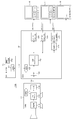
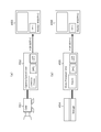
- FIG. 1 shows a configuration example of a camera system 10A as the first embodiment.
- This camera system 10A is configured such that a linear HDR (High Dynamic Range) video signal obtained by the camera 11 is transmitted to a camera control unit (CCU) 12 as a signal processing unit.
- CCU camera control unit
- linear means that gradation compression processing is not performed.
- the camera 11 and the CCU 12 are connected through a camera cable 13 made of an optical fiber or the like.
- the camera 11 includes a CPU 111, an imaging unit 112, a pre-process unit 113, and a transmission unit 114.
- the CPU 111 controls the operation of each unit of the camera 11 and further communicates with the CPU 121 of the CCU 12 through the camera cable 13.
- the imaging unit 112 includes, for example, an UHD (8K, 4K, etc.) or HD resolution image sensor, and outputs an HDR video signal as a captured video signal.
- the 4K resolution is a resolution of horizontal: about 4000 ⁇ vertical: about 2000 pixels, for example, 4096 ⁇ 2160 or 3840 ⁇ 2160
- the 8K resolution is a resolution in which the vertical and horizontal pixels are each twice the 4K resolution. It is.
- the HD resolution is, for example, a resolution in which the vertical and horizontal pixels are 1/2 times the 4K resolution.
- the pre-processing unit 113 is a processor configured by a circuit such as an FPGA (field-programmable gate array) or an ASIC (Application Specific-Integrated Circuit), for example, a lens for the HDR video signal output from the imaging unit 112.
- the optical system correction process and the correction process caused by variations in image sensors are performed.
- the transmission unit 114 is a circuit having a communication interface, and transmits the HDR video signal processed by the preprocessing unit 113 to the CCU 12.
- the CCU 12 includes a CPU 121, a transmission unit 122, an HDR camera process (HDR-CAM-Process) unit 123, an OETF-A / formatter unit 124, an OETF-B / formatter unit 125, an OOTF-C unit 126, an inverse It has an EOTF-C / formatter unit 127.
- the CPU 121 controls the operation of each unit of the CCU 12 and further communicates with the CPU 111 of the camera 11 through the camera cable 13 and is connected via a communication path 14 such as a LAN (Local Area Network). Communication is performed with the CPU 151 of the panel (Control Panel) 15.
- a communication path 14 such as a LAN (Local Area Network). Communication is performed with the CPU 151 of the panel (Control Panel) 15.
- the control panel 15 has an operation input unit 152 in addition to the CPU 151.
- the CPU 151 accepts various control commands and setting information input from the operation input unit 152 by a producer such as VE (Video Engineer), and sends it to the CPU 121 of the CCU 12 via the communication path 14.
- VE Video Engineer
- the transmission unit 122 is a circuit having a communication interface, and receives a linear HDR video signal sent from the camera 11.
- the HDR camera process unit 123 is a processor configured by a circuit such as an FPGA or an ASIC, and performs processing such as color gamut conversion and detail (contour) correction on the linear HDR video signal received by the transmission unit 122. Do.
- FIG. 2 shows a detailed configuration example of the HDR camera process unit 123.
- the HDR camera process unit 123 includes an HDR gain adjustment unit 131, a linear-matrix unit 132, a black-level unit 133, and a detail unit 134.
- the HDR gain adjustment unit 131 controls the master gain for the linear HDR video signal (Linear HDR Video) received by the transmission unit 122 (see FIG. 1), and performs R, G, The gain of each primary color signal of B is controlled.
- the linear matrix unit 132 performs color gamut conversion processing on the HDR video signal output from the HDR gain adjustment unit 131.
- the black level unit 133 adjusts the black level of the HDR video signal output from the linear matrix unit 132.
- the detail unit 134 performs detail (contour) correction processing on the HDR video signal output from the black level unit 133.
- the HDR video signal output from the detail unit 134 becomes the output of the HDR camera process unit 123.
- the OETF-A / formatter unit 124 is a processor configured by a circuit such as an FPGA or an ASIC, and a signal interface A for the linear HDR video signal output from the HDR camera process unit 123. Tone compression processing is performed.
- the gradation compression processing here means processing to perform bit length compression from the linear region using an opto-electrical transfer function (OETF) for the signal interface A.
- OETF opto-electrical transfer function
- the signal interface A is “S-Log3”.
- the OETF-A / formatter unit 124 converts the HDR video signal subjected to gradation compression in this way from the RGB domain to the Y color difference domain, and the HDR video signal subjected to the gradation compression processing of the signal interface A. Obtain “HDR OETF-A”.
- the HDR video signal “HDRETFOETF-A” obtained by the OETF-A / formatter unit 124 of the CCU 12 can be monitored by the monitor 16 corresponding to the signal interface A.
- the monitor 16 has an inverse / OETF-A section and an OOTF-A section.
- the inverse / OETF-A unit performs gradation expansion processing corresponding to the gradation compression processing of the signal interface A on the HDR video signal “HDR OETF-A”.
- the gradation expansion processing here is performed using the inverse characteristic of the photoelectric transfer function (OETF) for the signal interface A.
- the OOTF-A unit adds the system gamma characteristic of the signal interface A to the HDR video signal “HDR OETF-A”. As a result, the video displayed on the monitor 16 is corrected by the system gamma characteristic of the signal interface A.
- the OETF-B / formatter unit 125 is a processor composed of a circuit such as an FPGA or an ASIC, for example, and performs gradation compression processing of the signal interface B on the linear HDR video signal output from the HDR camera process unit 123.
- the gradation compression process here means a process of compressing the bit length from the linear region using the photoelectric transfer function (OETF) for the signal interface B.
- the signal interface B is “HLG (Hybrid Log-Gamma)”.
- the OETF-B / formatter unit 125 converts the HDR video signal, which has been tone-compressed in this way, from the RGB domain to the Y color difference domain, and has been subjected to the tone compression processing of the signal interface B. Obtain “HDR OETF-B”.
- the HDR video signal “HDRETFOETF-B” obtained by the OETF-B / formatter unit 125 of the CCU 12 can be monitored by the monitor 17 corresponding to the signal interface B.
- the monitor 17 has an inverse / OETF-B section and an OOTF-B section.
- the inverse OETF-B unit performs gradation expansion processing corresponding to the gradation compression processing of the signal interface B on the HDR video signal “HDR OETF-B”.
- the gradation expansion processing here is performed using the inverse characteristic of the photoelectric transfer function (OETF) for the signal interface B.
- the OOTF-B unit adds the system gamma characteristic of the signal interface B to the HDR video signal “HDR OETF-B”. As a result, the video displayed on the monitor 17 is corrected by the system gamma characteristic of the signal interface B.
- the OOTF-C unit 126 is a processor configured by a circuit such as an FPGA or an ASIC, for example, and performs a system gamma (OOTF: Opto: signal interface C) on the linear HDR video signal output from the HDR camera process unit 123. -Optical Transfer Function) is added.
- OOTF Opto: signal interface C
- the inverse EOTF-C / formatter unit 127 is a processor composed of circuits such as an FPGA and an ASIC, for example, and performs gradation compression processing of the signal interface C on the HDR video signal output from the OOTF-C unit 126.
- the gradation compression processing here means processing for compressing the bit length from the linear region by using the inverse characteristic of the electro-optical transfer function (EOTF) for the signal interface C.
- EOTF electro-optical transfer function
- the signal interface C is “PQ (Perceptual Quantizer)”.
- the inverse / EOTF-C / formatter unit 127 converts the HDR video signal subjected to gradation compression in this way from the RGB domain to the Y color difference domain, and has been subjected to the gradation compression processing of the signal interface C. Obtain the video signal “HDR EOTF-C”.
- the HDR video signal “HDREOTF-C” obtained by the OETF-C / formatter unit 127 of the CCU 12 can be monitored by the monitor 18 corresponding to the signal interface C.
- the monitor 18 has an EOTF-C unit.
- the EOTF-C unit performs gradation expansion processing corresponding to the gradation compression processing of the signal interface C on the HDR video signal “HDR EOTF-C”.
- the gradation expansion processing here is performed using an electro-optical transfer function (EOTF) for the signal interface C.
- EOTF electro-optical transfer function
- the CCU 12 can obtain an HDR video signal subjected to the gradation compression processing of the signal interfaces A, B, and C. Therefore, a camera system with improved usability can be provided.
- the camera system 10A shown in FIG. 1 is configured to simultaneously output HDR video signals subjected to gradation compression processing of the signal interfaces A, B, and C from the CCU 12, but any of these HDR video signals It is also possible to adopt a configuration for selectively outputting these.
- a processor processing unit
- OETF-A / formatter unit 124 OETF-B / formatter unit 125
- OOTF EOTF-C / formatter unit
- FIG. 3 shows an example of the configuration of a camera system 10B as the second embodiment. 3, parts corresponding to those in FIG. 1 are denoted by the same reference numerals, and detailed description thereof will be omitted as appropriate.
- This camera system 10B is configured to transmit a linear HDR video signal obtained by the camera 11 to a camera control unit (CCU) 12B as a signal processing unit.
- CCU camera control unit
- the CCU 12B includes a CPU 121, a transmission unit 122, an HDR camera process unit 123, an OETF-A / formatter unit 124, an OETF-B / formatter unit 125, an inverse / EOTF-C formatter unit 127, and an OOTF-A unit. 141 and 143 and an inverse / OOTF-B portion 142.
- the CPU 121 controls the operation of each part of the CCU 12B, and further communicates with the CPU 111 of the camera 11 through the camera cable 13 and also with the CPU 151 of the control panel 15 connected via the communication path 14 such as a LAN. Communicate between.
- the transmission unit 122 is a circuit having a communication interface, and receives a linear HDR video signal sent from the camera 11.
- the HDR camera process unit 123 performs processing such as color gamut conversion and detail (contour) correction on the linear HDR video signal received by the transmission unit 122.
- the OETF-A / formatter unit 124 performs gradation compression processing of the signal interface A on the linear HDR video signal output from the HDR camera process unit 123.
- the gradation compression process here means a process of compressing the bit length from the linear region using the photoelectric transfer function (OETF) for the signal interface A.
- the OETF-A / formatter unit 124 converts the HDR video signal subjected to gradation compression in this way from the RGB domain to the Y color difference domain, and the HDR video signal subjected to the gradation compression processing of the signal interface A. Obtain “HDR OETF-A”.
- the HDR video signal “HDRETFOETF-A” obtained by the OETF-A / formatter unit 124 of the CCU 12B can be monitored by the monitor 16 corresponding to the signal interface A.
- the monitor 16 has an inverse / OETF-A section and an OOTF-A section.
- the video displayed on the monitor 16 is corrected by the system gamma characteristic of the signal interface A.
- the OOTF-A unit 141 is a processor composed of, for example, a circuit such as an FPGA or an ASIC, and the system gamma (OOTF) of the signal interface A with respect to the linear HDR video signal output from the HDR camera process unit 123. Add properties.
- the inverse OOTF-B unit 142 is a processor composed of, for example, a circuit such as an FPGA or an ASIC, and the system gamma (OOTF) of the signal interface B with respect to the HDR video signal output from the OOTF-A unit 141. Add a characteristic that cancels the characteristic.
- the OETF-B / formatter unit 125 performs gradation compression processing of the signal interface B on the HDR video signal output from the inverse / OOTF-B unit 142.
- the gradation compression processing here means processing for compressing the bit length from the linear region using the photoelectric transfer function (EOTF) for the signal interface B.
- the OETF-B / formatter unit 125 converts the HDR video signal, which has been tone-compressed in this way, from the RGB domain to the Y color difference domain, and has been subjected to the tone compression processing of the signal interface B. Obtain “HDR OETF-B”.
- the HDR video signal “HDRHOETF-B” obtained by the OETF-B / formatter unit 125 of the CCU 12B can be monitored by the monitor 17 corresponding to the signal interface B.
- the monitor 17 has an inverse / OETF-B section and an OOTF-B section. Since the OOTF-A unit 141 and the inverse OOTF-B unit 142 exist in the system of the HDR video signal “HDR OETF-B” of the CCU 12B as described above, the video displayed on the monitor 17 is the above-described monitor. Similarly to the image displayed on the image 16, the image is corrected by the system gamma characteristic of the signal interface A.
- the OOTF-A unit 143 is a processor configured by a circuit such as an FPGA or an ASIC, for example, and the system gamma (OOTF) of the signal interface A with respect to the linear HDR video signal output from the HDR camera process unit 123. Add properties.
- the inverse / EOTF-C / formatter unit 127 performs gradation compression processing of the signal interface C on the HDR video signal output from the OOTF-A unit 143.
- the tone compression process here means a process of compressing the bit length from the linear region using the inverse characteristic of the electro-optical transfer function (EOTF) for the signal interface C.
- the inverse / EOTF-C / formatter unit 127 converts the HDR video signal subjected to gradation compression in this way from the RGB domain to the Y color difference domain, and has been subjected to the gradation compression processing of the signal interface C. Obtain the video signal “HDR EOTF-C”.
- OOTF-C In terms of signal interface, OOTF-C should be added, but OOTF-A includes OOTF-C, and signal processing with [OOTF-A-OOTF-C] applied as video correction It can be said that it is in line with the signal interface of EOTF-C.
- the HDR video signal “HDR EOF-C” obtained by the inverse / OETF-C / formatter unit 127 of the CCU 12B can be monitored by the monitor 18 corresponding to the signal interface C.
- the monitor 18 has an EOTF-C unit. Since the OOTF-A section 141 exists in the system of the HDR video signal “HDR OETF-C” of the CCU 12B and the OOTF-C section 126 (see FIG. 1) does not exist as described above, it is displayed on the monitor 18. Similar to the video displayed on the monitor 16 described above, the video is corrected by the system gamma characteristic of the signal interface A.
- the system gamma of the reference signal interface is used. And a process for canceling the system gamma characteristic of the other signal interface.
- the video is an HDR video signal subjected to gradation compression processing of the reference signal interface. It is the same as the video when monitoring with the interface compatible monitor (reference monitor). Therefore, even when outputting an HDR video signal subjected to gradation compression processing of a signal interface other than the reference signal interface, it is possible to perform camera adjustment (video adjustment) based on the video of the reference monitor. It becomes.
- the camera system 10B shown in FIG. 3 is configured to simultaneously output HDR video signals subjected to gradation compression processing of the signal interfaces A, B, and C from the CCU 12B. It is also possible to adopt a configuration for selectively outputting these.
- a processor processing unit
- OETF-A / formatter unit 124 or “OOTF-A unit 141, inverse / OOTF-B unit”.
- 142 and OOTF-B / formatter unit 125 ”or“ OOTF-A unit 143 and inverse / EOTF-C / formatter unit 127 ” can be selectively switched to reduce the circuit scale.
- FIG. 4 shows a configuration example of a camera system 10C as the third embodiment. 4, parts corresponding to those in FIGS. 1 and 3 are denoted by the same reference numerals, and detailed description thereof will be omitted as appropriate.
- the camera system 10C is configured such that a linear HDR video signal obtained by the camera 11 is transmitted to a camera control unit (CCU) 12C as a signal processing unit.
- CCU camera control unit
- the camera system 10C performs signal conversion processing on the HDR video signals output from the CCU 12C and subjected to gradation compression processing of the signal interface A by HDR converters (HDR-Converters) 19 and 20, respectively.
- HDR converters HDR-Converters
- the CCU 12C includes a CPU 121, a transmission unit 122, an HDR camera process unit 123, and an OETF-A / formatter unit 124.
- the CPU 121 controls the operation of each part of the CCU 12C, and further communicates with the CPU 111 of the camera 11 through the camera cable 13 and also with the CPU 151 of the control panel 15 connected via the communication path 14 such as a LAN. Communicate between.
- the transmission unit 122 is a circuit having a communication interface, and receives a linear HDR video signal sent from the camera 11.
- the HDR camera process unit 123 performs processing such as color gamut conversion and detail (contour) correction on the linear HDR video signal received by the transmission unit 122.
- the OETF-A / formatter unit 124 performs gradation compression processing of the signal interface A on the linear HDR video signal output from the HDR camera process unit 123.
- the gradation compression process here means a process of compressing the bit length from the linear region using the photoelectric transfer function (OETF) for the signal interface A.
- the OETF-A / formatter unit 124 converts the HDR video signal subjected to gradation compression in this way from the RGB domain to the Y color difference domain, and the HDR video signal subjected to the gradation compression processing of the signal interface A. Obtain “HDR OETF-A”.
- the HDR video signal “HDRETFOETF-A” obtained by the OETF-A / formatter unit 124 of the CCU 12C can be monitored by the monitor 16 corresponding to the signal interface A.
- the monitor 16 has an inverse / OETF-A section and an OOTF-A section.
- the video displayed on the monitor 16 is corrected by the system gamma characteristic of the signal interface A.
- the HDR converter 19 is a processor composed of, for example, a circuit such as an FPGA or an ASIC, and includes a deformator unit 144, an inverse / OTF-A unit 145, an OOTF-A unit 141, an inverse / OOTF-B unit 142, and the like. And an OETF-B / formatter unit 125.
- the deformatter unit 144 performs a conversion process from the Y color difference domain to the RGB domain on the HDR video signal “HDR OETF-A” subjected to the gradation compression process of the signal interface A output from the CCU 12C.
- the inverse / OETF-A unit 145 performs gradation expansion processing corresponding to the gradation compression processing of the signal interface A on the HDR video signal output from the deformator unit 144.
- the gradation expansion processing here is performed using the inverse characteristic of the photoelectric transfer function (OETF) for the signal interface A.
- the OOTF-A unit 141 adds a system gamma (OOTF) characteristic of the signal interface A to the linear HDR video signal output from the inverse / OETF-A unit 145.
- the inverse / OOTF-B unit 142 adds a characteristic for canceling the system gamma (OOTF) characteristic of the signal interface B to the HDR video signal output from the OOTF-A unit 141.
- the OETF-B / formatter unit 125 performs gradation compression processing of the signal interface B on the HDR video signal output from the inverse / OOTF-B unit 142.
- the gradation compression process here means a process of compressing the bit length from the linear region using the photoelectric transfer function (OETF) for the signal interface B.
- the OETF-B / formatter unit 125 converts the HDR video signal, which has been tone-compressed in this way, from the RGB domain to the Y color difference domain, and has been subjected to the tone compression processing of the signal interface B. Obtain “HDR OETF-B”.
- the HDR video signal “HDRETFOETF-B” obtained by the HDR converter 19 can be monitored by the monitor 17 corresponding to the signal interface B.
- the monitor 17 has an inverse / OETF-B section and an OOTF-B section. Since the HDR converter 19 includes the OOTF-A unit 141 and the inverse / OOTF-B unit 142 as described above, the video displayed on the monitor 17 is the same as the video displayed on the monitor 16 described above. , Corrected by the system gamma characteristic of the signal interface A.
- the HDR converter 20 is a processor composed of a circuit such as an FPGA or an ASIC, for example, and includes a formatter unit 146, an inverse / OETF-A unit 147, an OOTF-A unit 143, and an inverse / EOTF-C / formatter unit. 127.
- the deformformer unit 146 performs conversion processing from the Y color difference domain to the RGB domain on the HDR video signal “HDR OETF-A” subjected to the gradation compression processing of the signal interface A output from the CCU 12C.
- the inverse / OETF-A unit 147 performs gradation expansion processing corresponding to the gradation compression processing of the signal interface A on the HDR video signal output from the deformator unit 146.
- the gradation expansion processing here is performed using the inverse characteristic of the photoelectric transfer function (OETF) for the signal interface A.
- the OOTF-A unit 143 adds a system gamma (OOTF) characteristic of the signal interface A to the linear HDR video signal output from the inverse / OETF-A unit 147.
- the inverse / EOTF-C / formatter unit 127 performs gradation compression processing of the signal interface C on the HDR video signal output from the OOTF-A unit 143.
- the tone compression process here means a process of compressing the bit length from the linear region using the inverse characteristic of the electro-optical transfer function (EOTF) for the signal interface C.
- the inverse / EOTF-C / formatter unit 127 converts the HDR video signal subjected to gradation compression in this way from the RGB domain to the Y color difference domain, and has been subjected to the gradation compression processing of the signal interface C. Obtain the video signal “HDR EOTF-C”.
- the HDR-C video signal “HDRHEOTF-C” thus obtained by the HDR converter 20 can be monitored by the monitor 18 corresponding to the signal interface C.
- the monitor 18 has an EOTF-C unit. Since the HDR converter 20 includes the OOTF-A unit 141 as described above and the OOTF-C unit 126 (see FIG. 1), the video displayed on the monitor 18 is displayed on the monitor 16 described above. In the same way as the video displayed on the screen, it is corrected by the system gamma characteristic of the signal interface A.
- the reference signal interface A process for adding the system gamma characteristic of the other signal interface and a process for canceling the system gamma characteristic of the other signal interface are performed.
- the video is an HDR video signal subjected to gradation compression processing of the reference signal interface. It is the same as the video when monitoring with the interface compatible monitor (reference monitor). Therefore, even when outputting an HDR video signal subjected to gradation compression processing of a signal interface other than the reference signal interface, it is possible to perform camera adjustment (video adjustment) based on the video of the reference monitor. It becomes.
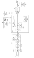
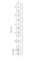
- FIG. 5 shows a configuration example of a video system 30 as the fourth embodiment.
- the video system 30 has a predetermined number of camera systems including two cameras 31 and a camera control unit (CCU: Camera Control Unit) 32 in the illustrated example.
- the camera 31 and the CCU 32 are connected via a camera cable 33.
- CCU Camera Control Unit
- a control panel 35 is connected to the CCU 32 via a communication path 34 such as a LAN.
- a communication path 34 such as a LAN.
- HDR High Dynamic Range
- SDR Standard Dynamic Range
- the signal interface A is a reference signal interface (unified signal interface), for example, the signal interface A is “S-Log3”.
- the video system 30 converts the HDR signal subjected to the gradation compression processing of the signal interface other than the signal interface A into the HDR signal (HDR-A video signal) subjected to the gradation compression processing of the signal interface A.
- the HDR converter 36 is a processor composed of a circuit such as an FPGA or an ASIC.
- the HDR converter 36 is, for example, an HDR video signal (HDR-B video signal) that has been subjected to gradation compression processing of the signal interface B, or an HDR video signal (HDR--) that has been subjected to gradation compression processing of the signal interface C.
- C video signal is converted into an HDR-A video signal.
- the signal interface B is “HLG (Hybrid Log-Gamma)”
- the signal interface C is “PQ (Perceptual Quantizer)”.
- the video system 30 also includes a server 37 that can record and reproduce HDR-A video signals.
- the HDR-A video signal recorded in the server 37 includes the HDR-A video signal output from the CCU 32 and the HDR-A video signal output from the HDR converter 36.
- the camera system, the HDR converter 36, the server 37, and the like constitute input devices.
- the video system 30 has a switcher 38.
- the HDR-A video signal output from the CCU 32 of the camera system is input to the switcher 38 via the transmission path 39.
- the HDR-A video signal information and the SDR video signal information are added to the HDR-A video signal output from the CCU 32 of the camera system.
- the SDR video signal output from the CCU 32 of the camera system is supplied to the SDR monitor 41 via the transmission path 40 and monitored.
- the HDR-A video signal output from the HDR converter 36 is input to the switcher 38 via the transmission path 42.
- the HDR-A video signal reproduced from the server 37 is also input to the switcher 38.
- the server 37 is supplied with an HDR-A signal to be recorded from the switcher 38.
- the switcher 38 selectively extracts a predetermined HDR-A video signal from HDR-A video signals input from a plurality of input devices such as the camera system, the HDR converter 36, and the server 37.
- the predetermined HDR-A video signal taken out by the switcher 38 is transmitted through the main transmission line 43.
- the HDR-A video signal is supplied to the monitor 45 corresponding to the signal interface A through the transmission path 44 and monitored.
- the video system 30 also converts an HDR-A video signal transmitted through the main transmission path 43 into an HDR signal (HDR-Converter) 46 that converts the gradation compression processing of a signal interface other than the signal interface A into a gradation signal.
- the HDR converter 46 is a processor composed of a circuit such as an FPGA or an ASIC.
- the HDR converter 46 converts the HDR-A video signal into, for example, an HDR-B video signal or an HDR-C video signal.
- the HDR video signal obtained by the HDR converter 46 is supplied to the monitor 48 of the corresponding signal interface via the transmission path 47 and monitored.
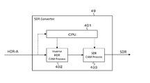
- the video system 30 also includes an SDR converter (SDR converter) 49 that converts an HDR-A video signal transmitted through the main transmission line 43 into an SDR video signal.
- SDR converter SDR converter
- FIG. 6 shows a configuration example of the camera 31, the CCU 32, the control panel 35, and the like.
- the camera 31 includes a CPU 311, an imaging unit 312, a pre-process unit 313, and a transmission unit 314.
- the CPU 311 controls the operation of each unit of the camera 31 and further communicates with the CPU 321 of the CCU 32 through the camera cable 33.
- the imaging unit 312 includes, for example, an UHD (8K, 4K, etc.) or HD resolution image sensor, and outputs an HDR video signal as a captured video signal.
- the pre-processing unit 313 is a processor configured by a circuit such as an FPGA (field-programmable gate array) or an ASIC (Application Specific integrated circuit), and a lens for the HDR video signal output from the imaging unit 312. Correction processing of the optical system of the above, and scratch correction processing caused by variations in the image sensor are performed.
- the transmission unit 314 is a circuit having a communication interface, and transmits the HDR video signal processed by the preprocessing unit 313 to the CCU 32.
- the CCU 32 includes a CPU 321, a transmission unit 322, an HDR camera process (HDR-CAM Process) unit 323, and an SDR camera process (SDR CAM Process) unit 324.
- the CPU 321 controls the operation of each part of the CCU 32 and further communicates with the CPU 311 of the camera 31 through the camera cable 33 and is connected via a communication path 34 such as a LAN (Local Area Network). Communication is performed with the CPU 351 of the panel (Control Panel) 35.
- a communication path 34 such as a LAN (Local Area Network). Communication is performed with the CPU 351 of the panel (Control Panel) 35.
- the control panel 35 has an operation input unit 352 in addition to the CPU 351.
- the CPU 351 accepts various control commands and setting information input from the operation input unit 352 by a producer such as VE (Video Engineer), and sends it to the CPU 321 of the CCU 32 via the communication path 34.
- VE Video Engineer
- the transmission unit 322 is a circuit having a communication interface and receives a linear HDR video signal sent from the camera 31.
- the HDR camera process unit 323 is a processor configured by a circuit such as an FPGA or an ASIC, for example, and performs color gamut conversion, detail (contour) correction, gradation compression on a linear HDR video signal received by the transmission unit 322.
- the HDR video signal subjected to the gradation compression processing of the signal interface A that is, the HDR-A video signal “HDR OETF-A” is obtained and transmitted to the transmission line 39.
- the gradation compression processing here means processing to perform bit length compression from the linear region using an opto-electrical transfer function (OETF) for the signal interface A.
- the SDR camera process unit 324 is a processor configured by a circuit such as an FPGA or an ASIC, for example, and performs level (gain) conversion, color gamut conversion, knee correction, linear HDR video signal received by the transmission unit 322, Detail (contour) correction, gamma processing, and the like are performed to obtain an SDR video signal, which is sent to the transmission path 40.
- the HDR-A video signal “HDRHOETF-A” obtained by the HDR camera process unit 323 includes information on the HDR-A video signal and the SDR obtained by the SDR camera process unit 324 under the control of the CPU 321.
- Video signal information is added.
- the CPU 321 may perform a process of multiplexing information in the HDR video stream, or may be transmitted to the transmission path 39 as a metadata file associated with the HDR data stream separately from the HDR video. It may be output.
- FIG. 7 shows a detailed configuration example of the HDR camera process unit 323 and the SDR camera process unit 324.
- This example is an example in which the HDR video signal has UHD (8K, 4K, etc.) resolution, and the SDR camera process unit 324 may be provided with a resolution conversion unit. It may be output.
- the HDR camera process unit 323 includes an HDR gain adjustment unit 331, a linear-matrix unit 332, a black-level unit 333, a detail unit 334, and an OETF-A / formatter unit. 335.
- the HDR gain adjustment unit 331 controls the master gain for the linear HDR video signal (Linear HDR Video) received by the transmission unit 322 (see FIG. 6), and performs R, G, The gain of each primary color signal of B is controlled.
- the linear matrix unit 332 performs linear matrix processing for color gamut conversion on the HDR video signal output from the HDR gain adjustment unit 331 as necessary.
- the processing contents here are HDR adjustment parameters as HDR-Color-Gamut information.
- the black level unit 333 adjusts the black level of the HDR video signal output from the linear matrix unit 222 based on black level correction information (HDR-Black) that is part of the HDR adjustment parameter information. do.
- the detail unit 334 performs detail (contour) correction processing on the HDR video signal output from the black level unit 333.
- the OETF-A / formatter unit 335 performs gradation compression processing of the signal interface A on the HDR video signal output from the detail unit 334 based on OETF information (OETF) which is a part of parameter information for HDR adjustment. I do.
- OETF OETF information
- the gradation compression process here means a process of compressing the bit length from the linear region using the photoelectric transfer function (OETF) for the signal interface A.
- the OETF-A / formatter unit 335 converts the gradation-compressed HDR video signal from the RGB domain to the Y color difference domain to obtain an output HDR-A video signal “HDR OETF-A”.
- the CPU 321 uses, for example, parameter information for HDR adjustment (“HDR-Color ⁇ ⁇ ⁇ ⁇ ⁇ Gamut”, “HDR-Black”, “OETF”) as the HDR-A video signal information, and the HDR-A video signal “HDR OETF-A”. To be transmitted.
- the SDR camera process unit 324 includes a resolution conversion unit 341, an SDR gain adjustment unit 342, a linear matrix (Linear-Matrix) unit 343, a black level unit 344, a knee detail (Detail). ) Part 345 and a gamma / formatter part 346.
- the resolution conversion unit 341 may convert the resolution of the linear HDR video signal (Linear HDR Video) received by the transmission unit 322 (see FIG. 6) from UHD to HD.
- the SDR gain adjustment unit 342 adds the linear HDR video signal output from the resolution conversion unit 341 based on the relative gain information (Relative-Gain) that is a part of the parameter information regarding the SDR video and the HDR video level. In addition to controlling the master gain, the gain of each primary color signal of R, G, B is controlled for white balance adjustment.
- the relative gain is a parameter indicating a ratio between a gain for the pixel signal in the HDR process and a gain for the pixel signal in the SDR process so that the contrast ratio between the HDR video and the SDR video can be adjusted.
- the relative gain defines how many times the dynamic range of the HDR video is set with respect to the dynamic range of the SDR video.
- the ratio of the master gain on the SDR process side to the master gain on the HDR process side can be set to an arbitrary ratio such as 1, 1/2, for example. In this way, if the ratio between the master gain on the HDR process side and the master gain on the SDR process side is set, the dynamic range of the HDR video having a correlation with the dynamic range of the SDR video can be obtained.
- the upper limit of the dynamic range of SDR video is given by the standard white (Diffuse-White) selected by the producer.
- the reference white (Diffuse-White) of the SDR video based on the correlation based on the relative gain, the HDR video dynamic range reference (HDR video reference white (Diffuse-White) )) Is also determined.
- the relative gain should be appropriately selected according to the shooting environment such as daytime, nighttime, indoors, outdoors, in the studio, in fine weather, in rainy weather, etc. Therefore, a relative gain is prepared as a variable that can cope with various shooting environments.
- a method of preparing the relative gain a method of comparing the apparent brightness of the SDR video and the HDR video simultaneously output from the CCU 32 with human eyes is conceivable. Each time the value of the relative gain is changed, the SDR video and the HDR video are compared, and the relative gain with which the apparent brightness of the SDR video and the HDR video is close may be determined as the optimal relative gain for the shooting environment.
- the relative gain may be information for performing white balance processing or contrast processing for SDR video.
- information other than the numerical value of the ratio to the gain of the HDR signal such as a gain value for RAW data that is a sensor output value. But it ’s okay.
- the luminance dynamic range of HDR video is wider than that of SDR video.
- the luminance dynamic range of the SDR video is 0 to 100%
- the luminance dynamic range of the HDR video is, for example, 0% to 1300% or 0% to 10000%.
- the linear matrix unit 343 adds color gamut information (SDR-Color Gamut) that is a part of SDR adjustment parameter information and information about the color of the SDR video to the HDR video signal output from the SDR gain adjustment unit 342.
- SDR-Color Gamut color gamut information
- the black level unit 344 adjusts the black level of the HDR video signal output from the linear matrix unit 343 based on the information (SDR-Black) for black level correction that is a part of the parameter information for SDR adjustment. do.
- the knee detail unit 345 performs knee correction on the HDR video signal output from the black level unit 344 based on knee correction information (KNEE), which is a part of parameter information for SDR adjustment, to generate an SDR video.
- KNEE knee correction information
- the signal is further subjected to detail (contour) correction on the SDR video signal.
- the gamma formatter unit 346 performs gamma processing on the linear SDR video signal output from the knee detail unit 345 based on gamma characteristic information (SDR-Gamma) which is a part of parameter information for SDR adjustment. Do. Further, the gamma formatter unit 346 converts the SDR video signal processed in this way from the RGB domain to the Y color difference domain to obtain an output SDR video signal.
- SDR-Gamma gamma characteristic information
- the CPU 321 includes, for example, SDR adjustment parameter information (“Relative-Gain”, “SDR-Color ⁇ Gamut ”,“ SDR-Black ”,“ KNEE ”,“ SDR-Gamma ”) as SDR video signal information. It is added to the HDR-A video signal “HDR OETF-A” and transmitted.
- SDR adjustment parameter information (“Relative-Gain”, “SDR-Color ⁇ Gamut ”,“ SDR-Black ”,“ KNEE ”,“ SDR-Gamma ” as SDR video signal information. It is added to the HDR-A video signal “HDR OETF-A” and transmitted.
- FIG. 8 shows another configuration example such as the camera 31, the CCU 32, the control panel 35, and the like. 8, parts corresponding to those in FIG. 6 are denoted by the same reference numerals, and detailed description thereof will be omitted as appropriate.
- the camera 31 includes a CPU 311, an imaging unit 312, a pre-process (Pre-Process) unit 313, an HDR camera process (HDR-CAM Process) unit 315, and a transmission unit 314.
- the HDR camera process unit 315 is a processor configured by a circuit such as an FPGA or an ASIC, for example, and performs color gamut conversion, detail (contour) correction, gradation on the linear HDR video signal processed by the preprocess unit 313. Processing such as compression is performed to obtain an HDR video signal subjected to gradation compression processing of the signal interface A, that is, an HDR-A video signal “HDR OETF-A”.
- the HDR camera process unit 315 has the same configuration as the HDR camera process unit 323 (see FIGS. 6 and 7) described above.
- the transmission unit 314 is a circuit having a communication interface, and transmits the HDR-A video signal “HDR OETF-A” obtained by the HDR camera process unit 315 to the CCU 32.
- the HDR-A video signal “HDR ⁇ OETF-A” obtained by the HDR camera process unit 315 is added with the information of the HDR-A video signal under the control of the CPU 311.
- This information is, for example, parameter information for HDR adjustment (“HDR”, similar to the information of the HDR-A video signal added to the HDR-A video signal “HDR OETF-A” obtained by the HDR camera process unit 323 described above.
- the CCU 32 includes a CPU 321, a transmission unit 322, an inverse / HDR camera process (Inverse HDR-CAM Process) unit 325, and an SDR camera process (SDR / CAM Process) unit 324.
- the CPU 321 controls the operation of each part of the CCU 32, and further communicates with the CPU 311 of the camera 31 through the camera cable 33 and is connected to the CPU 351 of the control panel 35 connected via a communication path 34 such as a LAN. Communicate between.
- the transmission unit 322 is a circuit having a communication interface, receives the HDR-A video signal “HDR OETF-A” sent from the camera 31, and outputs it to the transmission path 39.
- the HDR-A video signal “HDR OETF-A” includes, for example, parameter information for HDR adjustment (“HDR-Color Gamut”, “HDR-Black” as information of the HDR-A video signal. ”,“ OETF ”).
- the inverse / HDR camera process unit 325 is a processor including, for example, a circuit such as an FPGA or an ASIC, and performs RGB from the Y color difference domain to the HDR-A video signal “HDR OETF-A” received by the transmission unit 322.
- a linear HDR video signal is obtained by performing processing such as domain conversion and gradation compression inverse conversion.
- the operation of the inverse / HDR camera process unit 302 is performed based on the information of the HDR-A video signal added to the HDR-A video signal “HDR OETF-A” under the control of the CPU 321.
- the SDR camera process unit 324 performs level (gain) conversion, color gamut conversion, knee correction, detail (contour) correction, gamma processing, and the like on the linear HDR video signal obtained by the inverse / HDR camera process unit 325. Thus, an SDR video signal is obtained and sent to the transmission line 40.
- HDR-A video signal “HDRETFOETF-A” received by the transmission unit 322 is added with information on the HDR-A video signal “HDR OETF-A”.
- HDR OETF-A information on the SDR video signal obtained by the SDR camera process unit 324, for example, parameter information for SDR adjustment (“Relative-Gain” , “SDR-Color Gamut”, “SDR-Black”, “KNEE”, “SDR-Gamma”).
- FIG. 9 shows a detailed configuration example of the inverse / HDR camera process unit 325 and the SDR camera process unit 324.
- This example is an example in which the HDR video signal has UHD (8K, 4K, etc.) resolution, and the SDR camera process unit 324 includes a resolution conversion unit.
- the inverse HDR camera process unit 325 includes a deformer (De-Formatter) unit 361, an inverse OETF (Inverse-OETF) unit 362, and a remove black level (Remove-Black-level) unit 363. .
- Deformer De-Formatter
- inverse OETF Inverse-OETF
- remove black level Remove-Black-level
- the deformatter unit 361 performs conversion processing from the Y color difference domain to the RGB domain on the HDR-A video signal “HDR OETF-A” received by the transmission unit 322 (see FIG. 8).
- the inverse / OETF unit 362 performs inverse transformation of gradation compression on the HDR video signal output from the deformer unit 361 based on OETF information (OETF) which is a part of parameter information for HDR adjustment, A linear HDR video signal is obtained.
- OETF OETF information
- the remove / black level unit 363 converts the black level of the linear HDR video signal output from the inverse / OTF unit 362 into information (HDR-Black) for black level correction, which is a part of parameter information for HDR adjustment. Based on the above, the state before the adjustment in the black level part of the HDR camera process part 315 (see FIG. 8) is restored.
- the configuration of the SDR camera process unit 324 is the same as that described with reference to FIG.
- FIG. 10 shows a detailed configuration example of the HDR converter 36 and the HDR converter 46.
- the HDR converter 36 converts an HDR-B video signal into an HDR-A video signal
- the HDR converter 46 converts an HDR-A video signal into an HDR-B video signal.
- the HDR converter 36 has a deformer unit 370, an inverse / OETF-B unit 371, an OOTF-B unit 372, an inverse / OOTF-A unit 373, and an OETF-A / formatter unit 374.
- the deformatter unit 370 performs a conversion process from the Y color difference domain to the RGB domain on the input HDR-B video signal “HDR OETF-B” subjected to the gradation compression process of the signal interface B.
- the inverse / OETF-B unit 371 performs gradation expansion processing corresponding to the gradation compression processing of the signal interface B on the HDR video signal output from the deformator unit 370.
- the gradation expansion processing here is performed using the inverse characteristic of the photoelectric transfer function (OETF) for the signal interface B.
- the OOTF-B unit 372 adds the characteristic of the system gamma (OOTF) of the signal interface B to the linear HDR video signal output from the inverse / OETF-B unit 371.
- the inverse OOTF-A unit 373 adds a characteristic for canceling the system gamma (OOTF) characteristic of the signal interface A to the HDR video signal output from the OOTF-B unit 372.
- the OETF-A / formatter unit 374 performs gradation compression processing of the signal interface A on the HDR video signal output from the inverse / OOTF-A unit 373.
- the gradation compression process here means a process of compressing the bit length from the linear region using the photoelectric transfer function (OETF) for the signal interface A.
- the OETF-A / formatter unit 374 converts the HDR video signal, which has been tone-compressed in this way, from the RGB domain to the Y color-difference domain, and is subjected to tone compression processing of the signal interface A HDR-A
- the video signal “HDR OETF-A” is obtained and sent to the transmission line 42.
- the HDR converter 36 includes the OOTF-B unit 372 and the inverse / OOTF-A unit 373. Therefore, when the HDR-A video signal “HDR OETF-A” obtained by the HDR converter 36 is monitored by the monitor 45 corresponding to the signal interface A, the video displayed on the monitor 45 is input to the HDR converter 36. This is the same as the video displayed on the monitor 51 corresponding to the signal interface B for monitoring the HDR-B video signal “HDR OETF-B”.
- the HDR converter 46 has a deformer unit 375, an inverse / OETF-A unit 376, an OOTF-A unit 377, an inverse / OOTF-B unit 378, and an OETF-B / formatter unit 379.
- the deformformer unit 375 performs a conversion process from the Y color difference domain to the RGB domain on the HDR-A video signal “HDRETFOETF-A” subjected to the gradation compression process of the signal interface A taken out by the switcher 38. .
- the inverse / OETF-A unit 376 performs gradation expansion processing corresponding to the gradation compression processing of the signal interface A on the HDR video signal output from the deformer unit 375.
- the gradation expansion processing here is performed using the inverse characteristic of the photoelectric transfer function (OETF) for the signal interface A.
- the OOTF-A unit 377 adds a system gamma (OOTF) characteristic of the signal interface A to the linear HDR video signal output from the inverse / OETF-A unit 376.
- the inverse OOTF-B unit 378 adds a characteristic for canceling the system gamma (OOTF) characteristic of the signal interface B to the HDR video signal output from the OOTF-A unit 377.
- the OETF-B / formatter unit 379 performs gradation compression processing of the signal interface B on the HDR video signal output from the inverse / OOTF-B unit 378.
- the gradation compression process here means a process of compressing the bit length from the linear region using the photoelectric transfer function (OETF) for the signal interface B.
- the OETF-B / formatter unit 379 converts the HDR video signal subjected to gradation compression in this way from the RGB domain to the Y color difference domain, and performs HDR-B subjected to the gradation compression processing of the signal interface B. Obtain and output the video signal “HDR OETF-B”.
- the HDR-B video signal “HDR OETF-B” obtained by the HDR converter 46 can be monitored by the monitor 48 corresponding to the signal interface B.
- the HDR converter 46 includes an OOTF-A section 377 and an inverse / OOTF-B section 378. Therefore, the video displayed on the monitor 48 is the same as the video displayed on the monitor 45 that monitors the HDR-A video signal “HDR OETF-A” that is the input of the HDR converter 46.
- FIG. 11 also shows a detailed configuration example of the HDR converter 36 and the HDR converter 46.
- the HDR converter 36 converts an HDR-C video signal into an HDR-A video signal
- the HDR converter 46 converts the HDR-A video signal into an HDR-C video signal.
- the HDR converter 36 has a deformer unit 380, an EOTF-C unit 281, an inverse / OOTF-A unit 382, and an OETF-A / formatter unit 383.
- the deformatter unit 380 performs a conversion process from the Y color difference domain to the RGB domain on the input HDR-C video signal-C “HDR EOTF-C” subjected to the gradation compression process of the signal interface C.
- the EOTF-C unit 381 performs gradation expansion processing corresponding to the gradation compression processing of the signal interface C on the HDR video signal output from the deformator unit 380.
- the gradation expansion processing here is performed using an electro-optical transfer function (EOTF) for the signal interface C.
- EOTF electro-optical transfer function
- the inverse OOTF-A unit 382 adds a characteristic that cancels the system gamma (OOTF) characteristic of the signal interface A to the HDR video signal output from the EOTF-C unit 281.
- the OETF-A / formatter unit 383 performs gradation compression processing of the signal interface A on the HDR video signal output from the inverse / OOTF-A unit 382.
- the gradation compression process here means a process of compressing the bit length from the linear region using the photoelectric transfer function (OETF) for the signal interface A.
- the OETF-A / formatter unit 383 converts the HDR video signal subjected to gradation compression in this way from the RGB domain to the Y color difference domain, and performs HDR-A subjected to gradation compression processing of the signal interface A.
- the video signal “HDR OETF-A” is obtained and sent to the transmission line 42.
- the HDR converter 36 does not include the inverse / OOTF-C unit 126 (see FIG. 1) and includes the inverse / OOTF-A unit 382. Therefore, when the HDR-A video signal “HDR OETF-A” obtained by the HDR converter 36 is monitored by the monitor 45 corresponding to the signal interface A, the video displayed on the monitor 45 is input to the HDR converter 36. This is the same as the video displayed on the monitor 52 corresponding to the signal interface C for monitoring the HDR-C video signal “HDR OETF-C”.
- the HDR converter 46 has a deformer unit 385, an inverse / OETF-A unit 386, an OOTF-A unit 387, and an inverse / EOTF-C / formatter unit 388.
- the deformformer unit 385 performs a conversion process from the Y color difference domain to the RGB domain on the HDR-A video signal “HDR OETF-A” subjected to the gradation compression process of the signal interface A taken out by the switcher 38. .
- the inverse / OETF-A unit 386 performs gradation expansion processing corresponding to the gradation compression processing of the signal interface A on the HDR video signal output from the deformer unit 385.
- the gradation expansion processing here is performed using the inverse characteristic of the photoelectric transfer function (OETF) for the signal interface A.
- the OOTF-A unit 387 adds a system gamma (OOTF) characteristic of the signal interface A to the linear HDR video signal output from the inverse / OETF-A unit 386.
- the inverse / EOTF-C / formatter unit 388 performs gradation compression processing of the signal interface C on the HDR video signal output from the OOTF-A unit 387.
- the tone compression process here means a process of compressing the bit length from the linear region using the inverse characteristic of the electro-optical transfer function (EOTF) for the signal interface C.
- EOTF electro-optical transfer function
- the inverse / EOTF-C / formatter unit 388 converts the HDR video signal subjected to gradation compression in this way from the RGB domain to the Y color difference domain, and performs the gradation compression processing of the signal interface C.
- -C Obtain and output the video signal “HDR EOTF-C”.
- the HDR-C video signal “HDRHEOTF-C” thus obtained by the HDR converter 46 can be monitored by the monitor 48 corresponding to the signal interface C.
- the HDR converter 46 includes the OOTF-A unit 387 and does not include the OOTF-C unit 126 (see FIG. 1). Therefore, the video displayed on the monitor 48 is the same as the video displayed on the monitor 45 that monitors the HDR-A video signal “HDR OETF-A” that is the input of the HDR converter 46.
- the HDR converter 46 is a processor configured by a circuit such as an FPGA or an ASIC as described above.
- the video system 30 includes an HDR converter 46 that converts an HDR-A video signal “HDR OETF-A” to an HDR-B video signal “HDR OETF-B” as shown in FIG. 10 and the above-described FIG.
- the HDR converter 46 that converts the HDR-A video signal “HDR OETF-A” to the HDR-C video signal “HDR EOTF-C” can be provided in parallel, but the function of one HDR converter 46 can be provided.
- a configuration to be used by switching is also conceivable. In that case, only the output signal interface is set by the user, and the input signal interface is set automatically based on the information of the HDR video signal added to the HDR-A video signal “HDR OETF-A”. It may be done.
- FIG. 12 shows a configuration example of the SDR converter 49.
- the SDR converter 49 includes a CPU 401, an inverse / HDR camera process (Inverse HDR-CAM Process) unit 402, and an SDR camera process (SDR CAM Process) unit 403.
- the CPU 401 controls the operation of each unit of the SDR converter 49.
- the inverse / HDR camera process unit 402 is a processor composed of, for example, a circuit such as an FPGA or an ASIC, and the HDR-A video signal “HDR OETF which has been subjected to the gradation compression processing of the signal interface A taken out by the switcher 38.
- a linear HDR video signal is obtained by performing processing such as conversion from the Y color difference domain to the RGB domain and inverse conversion of gradation compression on “-A”.
- the operation of the inverse / HDR camera process unit 402 may be performed based on the information of the HDR-A video signal added to the HDR-A video signal “HDR OETF-A” under the control of the CPU 401. Good.
- the SDR camera process unit 403 performs level (gain) conversion, color gamut conversion, knee correction, detail (contour) correction, gamma processing, and the like on the linear HDR video signal obtained by the inverse / HDR camera process unit 402. To obtain and send an SDR video signal.
- the operation of the SDR camera process unit 403 may be performed based on the information of the SDR video signal added to the HDR-A video signal “HDR OETF-A” under the control of the CPU 401.
- FIG. 13 shows a detailed configuration example of the inverse / HDR camera process unit 402 and the SDR camera process unit 403.
- This example is an example in which the HDR video signal has UHD (8K, 4K, etc.) resolution, and the SDR camera process unit 403 may include a resolution conversion unit.
- the inverse HDR camera process unit 402 includes a deformer (De-Formatter) unit 421, an inverse OETF (Inverse-OETF) unit 422, and a remove black level (Remove-Black-level) unit 423. .
- the deformatter unit 421 performs conversion processing from the Y color difference domain to the RGB domain on the HDR-A video signal “HDR OETF-A” subjected to the gradation compression processing of the signal interface A taken out by the switcher 38. .
- the inverse / OETF unit 422 performs gradation compression inverse conversion on the HDR video signal output from the deformer unit 421 based on OETF information (OETF) which is part of the parameter information for HDR adjustment, A linear HDR video signal is obtained.
- OETF OETF information
- the remove black level unit 423 converts the black level of the linear HDR video signal output from the inverse / OTF unit 422 into information (HDR-Black) for black level correction, which is a part of parameter information for HDR adjustment. Return to the state before adjustment based on.
- the SDR camera process unit 403 includes a resolution conversion unit 431, an SDR gain adjustment unit 432, a linear matrix (Linear-Matrix) unit 433, a black level (Black-level) unit 434, and knee / detail (Detail). ) Section 435 and a gamma / formatter section 436.
- the resolution converter 431 converts the resolution of the linear HDR video signal (Linear HDR Video) obtained by the inverse / HDR camera process unit 402 from UHD to HD.
- the SDR gain adjustment unit 432 adds the relative gain information (Relative-Gain), which is a part of the parameter information regarding the SDR video and the HDR video level, to the linear HDR video signal converted into the HD resolution by the resolution conversion unit 431.
- the gains of the R, G, and B primary color signals may be controlled for white balance adjustment.
- the linear matrix unit 433 adds color gamut information (SDR-Color Gamut), which is part of the SDR adjustment parameter information and is information about the color of the SDR video, to the HDR video signal output from the SDR gain adjustment unit 432.
- SDR-Color Gamut color gamut information
- the black level unit 434 adjusts the black level of the HDR video signal output from the linear matrix unit 433 based on information (SDR-Black) for black level correction, which is a part of parameter information for SDR adjustment. do.
- the knee detail unit 435 performs knee correction on the HDR video signal output from the black level unit 434 based on knee correction information (KNEE), which is part of parameter information for SDR adjustment, and further Detail (contour) correction is performed on the SDR video signal.
- KNEE knee correction information
- the gamma formatter unit 436 adds the linear SDR video signal output from the knee detail unit 435 to dynamic range compression information (SDR-Gamma), which is a part of parameter information for SDR adjustment. Perform gamma processing.
- the gamma formatter unit 436 obtains an output SDR video signal by converting the RGB domain to the Y color difference domain.
- the switcher 38 converts the HDR-A video signal subjected to the gradation compression processing of the signal interface A, which is the reference signal interface (unified signal interface), into the plurality of input devices.
- the predetermined HDR video signal taken out by the switcher 38 is always an HDR-A video signal that has been subjected to gradation compression processing of the reference signal interface. Therefore, it is possible to perform video adjustment of a plurality of input devices uniformly by monitoring with the monitor 45 corresponding to the reference signal interface (unified signal interface).
- the HDR converter 46 outputs at least the system gamma of the signal interface A when outputting the HDR video signal subjected to the gradation compression processing of the signal interface other than the signal interface A.
- the process of adding the characteristics is performed. Therefore, when an HDR video signal subjected to gradation compression processing of another signal interface is monitored by the monitor 48 corresponding to the interface, the video is monitored as described above for a predetermined HDR video signal corresponding to the signal interface A. It can be the same as the video (adjusted video) when monitoring with.
- the HDR converter 36 in the video system 30 converts an HDR-B video signal or an HDR-C video signal into an HDR-A video signal.
- the HDR converter 36 may have a function of changing the video.
- the HDR converter 36 has a signal processor 441 as shown in FIGS. 14A and 14B, for example.
- FIG. 14A shows a configuration example of the HDR converter 36 that converts an HDR-B video signal into an HDR-A video signal.
- FIG. 14B shows a configuration example of the HDR converter 36 that converts an HDR-C video signal into an HDR-A video signal.
- the signal processor 441 may have a function capable of manually adjusting the brightness.
- the signal processor 441 only needs to have a function capable of manually adjusting the color.
- FIGS. 15A and 15B the video signal generated in a state where the monitor side does not have the OOTF function as the HDR-B video signal or the HDR-C video signal input to the HDR converter 36.
- FIG. 15A shows an HDR-X video signal “HDRETFOETF obtained by processing a linear HDR signal from the camera 442 by a camera control unit (CCU) 443 and performing gradation compression processing of the signal interface X. This is an example of obtaining “ ⁇ X”, and indicates that the monitor 444 for monitoring this has no OOTF function.
- FIG. 15A shows an HDR-X video signal “HDRETFOETF obtained by processing a linear HDR signal from the camera 442 by a camera control unit (CCU) 443 and performing gradation compression processing of the signal interface X. This is an example of obtaining “ ⁇ X”, and indicates that the monitor 444 for monitoring this has no OOTF function.
- FIG. 15B shows an HDR-X video signal “HDR OETF obtained by processing a linear HDR signal from the storage 445 by a video processor unit (BPU) 446 and performing gradation compression processing of the signal interface X. This is an example of obtaining “ ⁇ X”, and indicates that the monitor 447 for monitoring this has no OOTF function.
- Case (1) An image when the camera image is simply captured as the material data of the image and no adjustment (so-called post-production) is performed as the image.
- Case (2) An image when it is included in the image adjustment as to what the image looks like in a monitor viewing environment without OOTF.
- FIG. 16A shows an example in which a linear HDR signal from the camera 451 is processed by a camera control unit (CCU) 452 to obtain an HDR-C video signal, and a monitor 453 corresponding to the signal interface C is shown. Shows that the video signal is being monitored.
- FIG. 16B shows an example in which a linear HDR signal from the storage 454 is processed by a video processor unit (BPU) 455 to obtain an HDR-C video signal.
- the monitor 456 corresponding to the signal interface C is shown in FIG. Shows that the video signal is being monitored.
- the HDR converter 36 does not perform the process of adding the system gamma (OOTF) characteristic, and the signal interface A What is necessary is just to perform signal processing so that it may become a desired image
- OOTF system gamma
- the OETF / EOTF signal interface conversion and the conversion destination All that is required is to cancel the system gamma (OOTF-A) of the signal interface A.
- FIG. 19 shows a configuration example of an HDR production live system 500 as the fifth embodiment.
- the HDR production live system 500 has a predetermined number of camera systems including a camera and a camera control unit (CCU).
- the camera system includes a camera 501 and a CCU 502, and the camera system includes a camera 511 and a CCU 512.
- the CCUs 502 and 512 perform image creation processing on the captured video signals from the cameras 501 and 511. From the CCUs 502 and 512, a high dynamic range (HDR: High Dynamic Range) video signal (HDR-A video signal) subjected to the gradation compression processing of the signal interface A is obtained.
- the signal interface A is a reference signal interface (unified signal interface).
- the signal interface A is “S-Log3”.
- the HDR production live system 500 includes a server 521 that records and reproduces a video file for replay reproduction and the like.
- the files recorded in the server 521 include video files acquired by communication from an external device such as a personal computer (PC) in addition to the files of the video signals 503 and 513 output from the CCUs 502 and 512.
- PC personal computer
- Video signals 503 and 513 output from the CCUs 502 and 512 are sent as SDI signals to the server 521 via a switcher 525 described later.
- Information of the signal interface A is added as metadata to, for example, the payload ID area and the VANC area of the SDI signal.
- the server 521 can recognize that the video signals 503 and 513 output from the CCUs 502 and 512 are HDR-A video signals, and the file of these video signals 503 and 513 includes a signal interface as its attribute information.
- the information of A is added.
- Signal interface information is similarly added to video files input from an external device such as a personal computer (PC), so that the server 521 recognizes what signal interface video signals are included in the file. it can.
- PC personal computer
- the video signal input from an external device such as a personal computer (PC) and included in the video file is not limited to the above-described HDR-A video signal, and the gradation compression processing of the signal interface B is performed.
- HDR video signal HDR-B video signal
- HDR video signal HDR-C video signal
- SDR Standard Dynamic Range
- the signal interface B is “HLG (Hybrid Log-Gamma)”
- the signal interface C is “PQ (Perceptual Quantizer)”.
- the HDR production live system 500 includes a monitor 523 for appropriately checking the video in the file recorded in the storage 537 when the operator of the server 521 operates.
- a video signal 522 corresponding to the signal interface supported by the monitor 523 is sent from the server 521 to the monitor 523 as an SDI signal.
- the monitor 523 is an HDR monitor corresponding to, for example, an SDR monitor or a signal interface B, and an SDR video signal or an HDR-B video signal is supplied as a video signal 522 from the server 521 to the monitor 523. .
- the HDR production live system 500 includes a switcher 525.
- HDR-A video signals 503 and 513 output from the CCUs 502 and 512 are input to the switcher 525 as SDI signals.
- signal interface A information is added as metadata to, for example, the payload ID area and VANC area of the SDI signal.
- the video signal 524 reproduced from the server 521 is also input to the switcher 525.
- This video signal 524 is an HDR video signal (HDR-A video signal) subjected to the gradation compression processing of the signal interface A, and is sent from the server 521 to the switcher 525 as an SDI signal.
- Information of the signal interface A is added as metadata to, for example, the payload ID area and the VANC area of the SDI signal.
- the switcher 525 selectively extracts and outputs a predetermined HDR-A video signal from HDR-A video signals input from a plurality of input devices such as a camera system and a server 521, or is input from a plurality of input devices. Any video signal among the HDR-A video signals is mixed and output.
- the HDR-A video signal 526 as the main line signal extracted by the switcher 525 is output as it is as an SDI signal.
- the HDR production live system 500 includes an HDR converter (HDR-Converter) 527.
- the predetermined HDR-A video signal 526 taken out by the switcher 525 is sent to the HDR converter 527 as an SDI signal.
- the HDR converter 527 converts the HDR-A video signal into an HDR video signal 528 such as an HDR-B video signal or an HDR-C video signal, and outputs it.
- the HDR video signal 528 is output as an SDI signal.
- Signal interface information is added as metadata to, for example, the payload ID area and VANC area of the SDI signal.
- FIG. 20 shows a configuration example of the server 521.
- the solid line arrows in the figure indicate the flow of signals, and the broken line arrows indicate the direction of control.
- two input systems and two output systems are provided, but the number of each system is not limited to this.
- the server 521 includes a CPU 531, SDI (Serial Digital Interface) input units 532-1 and 532-2, encoders 533-1 and 533-2, decoders 534-1 and 534-2, and OETF (Opto-Electrical Transfer). Function) conversion units 535-1 and 535-2, SDI output units 536-1 and 536-2, a storage 537, and a communication interface 538 are provided.
- SDI Serial Digital Interface
- encoders 533-1 and 533-2 encoders 533-1 and 533-2
- decoders 534-1 and 534-2 decoders 534-1 and 534-2
- OETF Opto-Electrical Transfer
- the CPU 531 controls the operation of each unit of the server 521.
- the SDI input units 532-1 and 532-2 receive an SDI signal and extract a video signal and metadata from the SDI signal. This metadata also includes signal interface information of the video signal included in the SDI signal.
- the SDI input units 532-1 and 532-2 send the metadata extracted from the SDI signal to the CPU 531. As a result, the CPU 531 can recognize what the signal interface of the video signal included in the SDI signal is.
- the encoders 533-1 and 533-2 perform a coding process using a compression format such as XAVC on the video signal extracted from the SDI signal by the SDI input units 532-1 and 532-2, and a file (recording file). Is generated. In addition, signal interface information of a video signal is added to this file as attribute information.
- the files generated by the encoders 533-1 and 533-2 are recorded in the storage 537 and played back under the control of the CPU 531.
- the SDI input unit 532-1 and the encoder 533-1 constitute a first input system.
- the SDI input unit 532-1 receives the HDR-A video signal 503 output from the CCU 502 as an SDI signal.
- the SDI input unit 532-2 and the encoder 533-2 constitute a second input system.
- the HDR-A video signal 513 output from the CCU 512 is received as an SDI signal.
- the communication interface 538 is, for example, an Ethernet interface, and communicates with a personal computer (PC) 550 as an external device to acquire a file (video file) related to a past video or a CG (Computer Graphics) video. And sent to the CPU 531. This file is recorded in the storage 537 and played back under the control of the CPU 531.
- PC personal computer
- CG Computer Graphics
- signal interface information of video signals is added as attribute information.
- the video signal included in the file may be an SDR video signal, and the HDR video signal also supports various signal interfaces such as an HDR-A video signal, an HDR-B video signal, and an HDR-C video signal. There is a possibility.
- the CPU 531 can also extract a file from the storage 537 and send it to the PC 550 through the communication interface 538.
- the PC 550 can edit the file and return the edited file to the storage 537.
- the decoders 534-1 and 534-2 perform a decoding process on a file (video file) reproduced from the storage 537 to obtain a baseband reproduced video signal.
- This reproduced video signal has been subjected to gradation compression processing corresponding to the first signal interface, and is an HDR-A video signal, HDR-B video signal, HDR-C video signal, SDR video signal, or the like. .
- the OETF conversion units 535-1 and 535-2 perform OETF conversion processing on the reproduced video signals obtained by the decoders 534-1 and 534-2, and gradation compression corresponding to the second signal interface which is an output signal interface An processed output video signal is obtained.
- the OETF conversion units 535-1 and 535-2 do not perform the OETF conversion process and the reproduced video signal. Are output video signals as they are.
- the OETF conversion units 535-1 and 535-2 make processing settings based on the information of the first signal interface of the reproduced video signal and the information of the second signal interface of the output video signal.
- the processing setting of the OETF conversion units 535-1 and 535-2 is performed based on the control of the CPU 531.
- the CPU 531 can obtain the information of the first signal interface of the reproduction video signal from the attribute information added to the file, and the information of the second signal interface of the output video signal from the setting information at the time of system configuration. Obtainable.
- the OETF conversion units 535-1 and 535-2 can perform independent processing settings.
- the reproduction video signal is obtained by continuous reproduction of a plurality of files recorded in the storage 537 as in playlist reproduction, for example, the OETF conversion units 535-1 and 535-2 reproduce reproduction video.
- the processing setting is changed according to the change in the information of the first signal interface of the signal.
- the SDI output units 536-1 and 536-2 output the output video signals obtained by the OETF conversion units 535-1 and 535-2 as SDI signals.
- the SDI output units 536-1 and 536-2 set the information of the second signal interface of the output video signal as metadata in, for example, the payload ID area or the VANC area of the SDI signal.
- the decoder 534-1, the OETF conversion unit 535-1, and the SDI output unit 536-1 constitute a first output system.
- the SDI output unit 536-1 outputs an HDR-A video signal 524 to be sent to the switcher 525 as an SDI signal.
- the decoder 534-2, the OETF conversion unit 535-2, and the SDI output unit 536-2 constitute a second output system.
- the SDI output unit 536-2 outputs an SDR video signal or HDR-B video signal to be sent to the monitor 523 as the SDI signal 522.
- FIG. 21 shows a configuration example of the OETF conversion unit 535 (535-1, 535-2).
- the OETF conversion unit 535 includes a recording-time inverse OETF unit 541, a recording-time OOTF unit 542, a color gamut conversion unit 543, a linear gain unit 544, an output inverse OOTF unit 545, and an output OETF unit 546.
- the reproduced video signal is a video signal of the signal interface X and the output video signal is a video signal of the signal interface Y.
- the recording inverse OETF unit 541 performs gradation expansion processing corresponding to the gradation compression processing of the signal interface X applied to the reproduced video signal on the reproduced video signal of the signal interface X.
- the gradation expansion processing here is performed using the inverse characteristic of the photoelectric transfer function (OETF) for the signal interface X.
- the recording time OOTF unit 542 adds the system gamma (OOTF) characteristic of the signal interface X to the output video signal of the recording time inverse OETF unit 541.
- the color gamut conversion unit 543 performs linear matrix processing for color gamut conversion on the output video signal of the OOTF unit 542 during recording.
- the linear gain unit 544 performs gain adjustment processing on the output video signal of the color gamut conversion unit 543.
- the color gamut conversion unit 543 is necessary only when it is necessary to convert the color gamut between the reproduced video signal and the output video signal. Further, the linear gain unit 544 is necessary when performing conversion from SDR to HDR, or conversely, conversion from HDR to SDR, between the reproduced video signal and the output video signal.
- the output inverse OOTF unit 545 adds a characteristic for canceling the system gamma (OOTF) characteristic of the signal interface Y to the output video signal of the linear gain unit 544.
- the output OETF unit 546 performs gradation compression processing of the signal interface Y on the output video signal of the output inverse OOTF unit 545.
- the gradation compression processing here is performed using the characteristics of the photoelectric transfer function (OETF) for the signal interface Y.
- the recording inverse OETF unit 541 and the recording OOTF unit 542 are set based on the signal interface X of the reproduced video signal, and the output inverse OOTF based on the signal interface Y of the output video signal.
- Section 545 and output OETF section 546 are set.
- the output OETF conversion unit 535 obtains an output video signal subjected to the tone compression processing of the signal interface Y from the reproduced video signal subjected to the tone compression processing of the signal interface X.
- FIG. 22 shows a representative example of actual setting values of the OETF conversion unit 535 (see FIG. 21).
- the example of (a) is an example in which the signal interface of the reproduced video signal (recording OETF) is “S-Log3” and the signal interface of the output video signal (output OETF) is “SDR”.
- the color gamut of the reproduced video signal is “BT.2020”
- the color gamut of the output video signal is “BT.709”.
- This example is used for the OETF conversion process on the server 521 side when the monitor 523 is an SDR monitor, for example.
- the recording inverse OETF unit 541 is set so as to perform gradation expansion processing (S-Log3 Inverse OETF) of “S-Log3”.
- the recording OOTF unit 542 is set so as to add the system gamma (OOTF) characteristic of “S-Log3”.
- the color gamut conversion unit 543 is set to perform linear matrix processing for converting the color gamut from “BT.2020” to “BT.709”.
- the linear gain unit 544 is set so that the gain decreases from the HDR gain to the SDR gain.
- the output inverse OOTF unit 545 is set not to perform processing, that is, to output the input as it is. Further, the output OETF unit 546 is set to perform gradation compression processing (SDR Inverse EOTF) of “SDR”.
- the example of (b) is an example in which the signal interface of the reproduced video signal (recording OETF) is “SDR” and the signal interface of the output video signal (output OETF) is “S-Log3”. is there.
- the color gamut of the reproduced video signal is “BT.709”, and the color gamut of the output video signal is “BT.2020”.
- This example is used, for example, when a file including a video signal whose signal interface is “SDR” is reproduced from the storage 537 and a video signal of “S-Log3” is input to the switcher 525.
- the recording inverse OETF unit 541 is set to perform the “SDR” gradation expansion process (SDR EOTF).
- the recording OOTF unit 542 is set not to perform processing, that is, to output the input as it is.
- the color gamut conversion unit 543 is set to perform linear matrix processing for converting the color gamut from “BT.709” to “BT.2020”.
- the linear gain unit 544 is set so that the gain increases from the SDR gain to the HDR gain.
- the output inverse OOTF unit 545 is set so as to cancel the system gamma (OOTF) characteristic of “S-Log3”. Further, the output OETF unit 546 is set to perform “S-Log3” gradation compression processing (S-Log3LogOETF).
- the example of (c) is an example in which the signal interface of the reproduced video signal (recording OETF) is “HLG” and the signal interface of the output video signal (output OETF) is “S-Log3”. is there.
- the color gamut of the reproduced video signal is “BT.2020” and the color gamut of the output video signal is “BT.2020”.
- This example is used, for example, when a file including a video signal whose signal interface is “HLG” is reproduced from the storage 537 and a video signal of “S-Log3” is input to the switcher 525.
- the recording inverse OETF unit 541 is set so as to perform the “HLG” gradation expansion processing (HLG Inverse OETF).
- the recording time OOTF unit 542 is set so as to add the system gamma (OOTF) characteristic of “HLG”.
- the color gamut conversion unit 543 is set not to perform processing, that is, to output the input as it is.
- the linear gain unit 544 is set not to perform processing, that is, to output the input as it is.
- the output inverse OOTF unit 545 is set so as to cancel the system gamma (OOTF) characteristic of “S-Log3”. Further, the output OETF unit 546 is set to perform “S-Log3” gradation compression processing (S-Log3LogOETF).
- the example of (d) is an example in which the signal interface of the reproduced video signal (recording OETF) is “PQ” and the signal interface of the output video signal (output OETF) is “S-Log3”. is there.
- the color gamut of the reproduced video signal is “BT.2020” and the color gamut of the output video signal is “BT.2020”.
- This example is used when, for example, a file including a video signal whose signal interface is “PQ” is reproduced from the storage 537 and a video signal of “S-Log3” is input to the switcher 525.
- the recording inverse OETF unit 541 is set so as to perform gradation expansion processing (PQ EOTF) of “PQ”.
- the recording OOTF unit 542 is set not to perform processing, that is, to output the input as it is.
- the color gamut conversion unit 543 is set not to perform processing, that is, to output the input as it is.
- the linear gain unit 544 is set not to perform processing, that is, to output the input as it is.
- the output inverse OOTF unit 545 is set so as to cancel the system gamma (OOTF) characteristic of “S-Log3”. Further, the output OETF unit 546 is set to perform “S-Log3” gradation compression processing (S-Log3LogOETF).
- the flowchart in FIG. 23 shows an example of control processing of the OETF conversion unit 535 (535-1, 535-2) by the CPU 531 when files having different material information (signal interface information) are continuously reproduced from the storage 537. Show.
- step S401 the CPU 531 acquires the EOTF setting of the output port, that is, the signal interface information of the output video signal.
- the CPU 531 acquires this information from, for example, setting information at the time of system configuration.
- step S402 the CPU 531 sets processing of the output inverse OOTF unit 545 and the output OETF unit 546 based on the EOTF setting of the output port.
- step S403 the CPU 531 acquires the attribute of the material to be reproduced, that is, the signal interface information of the reproduced video signal.
- the CPU 531 acquires this information from, for example, attribute information added to the file.
- step S404 the CPU 531 performs processing settings for the recording inverse OETF unit 541 and the recording OOTF unit 542 based on the attribute of the material to be reproduced.
- step S405 the CPU 531 sets processing settings of the color gamut conversion unit 543 and the linear gain unit 544 based on the EOTF setting of the output port acquired in step S401 and the attribute of the material to be reproduced acquired in step S403. To do. Thereafter, the CPU 531 performs a reproduction process in step S406.
- step ST407 the CPU 531 determines whether or not there is a material change.
- the CPU 531 can make this determination based on attribute information added to the file of the material to be reproduced.
- the CPU 531 returns to the process of step S406.
- the CPU 531 returns to the process of step S403 and performs the playback process after setting the process of each unit as described above.
- the server 521 outputs the reproduced video signal subjected to the gradation compression processing corresponding to the first signal interface to the output system (reproduction system). And an OETF conversion unit 535 (535-1, 535-2) for converting into an output video signal subjected to gradation compression processing corresponding to the second signal interface.
- the reproduced video signal subjected to the gradation compression process corresponding to the first signal interface is output from the reproduced video signal subjected to the gradation compression process corresponding to the second signal interface.
- the server 521 that converts to a video signal includes the OETF conversion unit 535 (535-1, 535-2).
- a similar OETF conversion unit is provided in the switcher 525, and the reproduced video signal subjected to the gradation compression process corresponding to the first signal interface in the switcher 525 is subjected to the gradation compression process corresponding to the second signal interface. It is also conceivable to convert the output video signal into a converted output video signal.
- the signal interface A for example, “S-Log3” is used as the reference signal interface (unified signal interface).
- the signal interface B for example, “HLG (Hybrid Log-Gamma)” or the signal interface C, for example, “PQ (Perceptual Quantizer)” may be used as the reference signal interface (unified signal interface).
- the present technology is applied to a camera system or a video system that handles three types of signal interfaces A to C.
- the present technology may be used together with or separately from these.
- the present invention can be similarly applied to a camera system or a video system that handles a plurality of types of signal interfaces.
- a processing unit for processing a linear high dynamic range video signal to obtain a high dynamic range video signal subjected to gradation compression processing is provided.
- the processing unit is capable of performing gradation compression processing of a plurality of signal interfaces.
- the processing unit The signal processing apparatus according to (1), wherein when performing gradation compression processing of a signal interface other than the reference signal interface, at least processing for adding a system gamma characteristic of the reference signal interface is further performed.
- the processing unit has a processing step of processing a linear high dynamic range video signal to obtain a high dynamic range video signal subjected to gradation compression processing, The signal processing method, wherein the processing unit is capable of performing gradation compression processing of a plurality of signal interfaces.
- an imaging unit for obtaining a linear high dynamic range video signal
- a processing unit for processing the linear high dynamic range video signal to obtain a high dynamic range video signal subjected to gradation compression
- the camera unit is capable of performing gradation compression processing of a plurality of signal interfaces.
- a processing unit for processing a linear high dynamic range video signal to obtain a high dynamic range video signal subjected to gradation compression processing of a reference signal interface A signal conversion unit that converts a high dynamic range video signal subjected to gradation compression processing of the reference signal interface into a high dynamic range video signal subjected to gradation compression processing of a signal interface other than the reference signal interface With The signal converter is To the high dynamic range video signal that has been subjected to the gradation compression processing of the reference signal interface, the gradation expansion processing corresponding to the gradation compression processing of the reference signal interface and the system gamma characteristic of the reference signal interface are added.
- a signal processing apparatus that performs processing and processing for canceling the system gamma characteristic of the other signal interface and gradation compression processing of the other signal interface.
- (6) a processing step for processing the linear high dynamic range video signal to obtain a high dynamic range video signal subjected to the gradation compression processing of the reference signal interface;
- a signal converter converts the high dynamic range video signal subjected to the gradation compression processing of the reference signal interface into a high dynamic range video signal subjected to the gradation compression processing of another signal interface other than the reference signal interface.
- an imaging unit for obtaining a linear high dynamic range video signal A processing unit for processing the linear high dynamic range video signal to obtain a high dynamic range video signal subjected to gradation compression processing of the reference signal interface;
- a signal conversion unit that converts a high dynamic range video signal subjected to gradation compression processing of the reference signal interface into a high dynamic range video signal subjected to gradation compression processing of a signal interface other than the reference signal interface With The signal converter is
- the high dynamic range video signal subjected to the gradation compression processing of the reference signal interface has at least the gradation expansion processing corresponding to the gradation compression processing of the reference signal interface and the system gamma characteristics of the reference signal interface.
- a camera system that performs each of the additional processing and the gradation compression processing of the other signal interface.
- An input unit having a plurality of input devices for inputting a high dynamic range video signal subjected to gradation compression processing of the reference signal interface;
- An extraction unit for selectively extracting a predetermined high dynamic range video signal from the plurality of input devices;
- An output unit that outputs a video signal based on the predetermined high dynamic range video signal;
- the output section In addition to the high dynamic range video signal subjected to gradation compression processing of the reference signal interface, at least a high dynamic range video signal subjected to gradation compression processing of a signal interface other than the reference signal interface is output.
- the output section When outputting a high dynamic range video signal subjected to gradation compression processing of the other signal interface, the gradation corresponding to at least the gradation compression processing of the reference signal interface is added to the predetermined high dynamic range video signal.
- the decompression process, the process of adding the system gamma characteristic of the reference signal interface, and the gradation compression process of the other signal interface were performed, and the gradation compression process of the other signal interface was performed.
- a video system that obtains high dynamic range video signals.
- the input unit includes a camera system, The camera system An imaging unit for obtaining a linear high dynamic range video signal;
- the input unit outputs a high dynamic range video signal subjected to gradation compression processing of a signal interface other than the reference signal interface to a high dynamic range subjected to gradation compression processing of the reference signal interface.
- the signal converter is The high dynamic range video signal that has been subjected to the gradation compression processing of the other signal interface, at least the gradation expansion processing corresponding to the gradation compression processing of the other signal interface, and the system gamma of the reference signal interface
- the output unit The video system according to any one of (8) to (10), wherein a normal (standard) dynamic range video signal is further output.
- the predetermined high dynamic range video signal includes information on the normal (standard) dynamic range video signal generated based on the predetermined high dynamic range video signal, together with information on the predetermined high dynamic range video signal. Is added, The output section When outputting the normal (standard) dynamic range video signal, the predetermined high dynamic range video signal is processed based on the information added to the predetermined high dynamic range video signal, and the normal (standard) video signal is output. ) Obtaining a dynamic range video signal The video system according to (11).
- a reproducing unit that reproduces a file recorded in the storage and obtains a reproduced video signal subjected to gradation compression processing corresponding to the first signal interface;
- a server comprising a processing unit that processes the reproduced video signal to obtain an output video signal subjected to gradation compression processing corresponding to the second signal interface.
- the processing unit The server according to (13), wherein processing setting is performed based on information on the first signal interface of the reproduced video signal and information on the second signal interface of the output video signal.
- the processing unit When the playback video signal is obtained by continuous playback of a plurality of files recorded in the storage, The server according to (14), wherein the processing setting is changed according to a change in information of the first signal interface of the reproduction video signal.
- (16) having a plurality of output systems of the reproduction unit and the processing unit;
- (17) The server according to any one of (13) to (16), further including an information superimposing unit that superimposes information on the second signal interface on the output video signal.
- HDR camera process unit 324 ... SDR camera process unit 325 ... Inverse / HDR camera process unit 331 ... HDR gain adjustment unit 332 ... Linear matrix unit 333 Black level part 334 Detail part 335 OETF-A formatter part 341 Resolution conversion part 342 SDR gain adjustment part 343 Linear matrix part 344 Black level part 345 ... Knee detail part 346 ... Gamma formatter part 351 ...
- OETF-A ⁇ Formatter unit 385 Deformatter unit 386 ⁇ Inverse ⁇ OETF unit 387 ⁇ ⁇ ⁇ OOTF-A unit 3 8 ... Inverse ⁇ EOTF-C ⁇ formatter unit 401 ⁇ CPU 402 ... Inverse / HDR camera process unit 403 ... SDR camera process unit 421 ... SDR deformator unit 422 ... Inverse / OETF unit 423 ... Remove / Black level unit 431 ... Resolution conversion unit 432 ... SDR gain adjustment section 433 ... linear matrix section 434 ... black level section 435 ... knee detail section 436 ... gamma formatter section 441 ... signal processor 442 ... camera 443 ...
Landscapes
- Engineering & Computer Science (AREA)
- Multimedia (AREA)
- Signal Processing (AREA)
- Physics & Mathematics (AREA)
- General Physics & Mathematics (AREA)
- Theoretical Computer Science (AREA)
- Studio Devices (AREA)
- Picture Signal Circuits (AREA)
- Processing Of Color Television Signals (AREA)
Abstract
複数の信号インタフェースのHDR映像信号の取り扱いを良好に行い得るようにする。 【解決手段】処理部は、リニアなハイダイナミックレンジ映像信号を処理して階調圧縮処理が施されたハイダイナミックレンジ映像信号を得る。処理部は、複数の信号インタフェースの階調圧縮処理を行うことが可能とされている。例えば、処理部は、基準信号インタフェース以外の他の信号インタフェースの階調圧縮処理を行うとき、基準信号インタフェースのシステムガンマの特性を付加する処理および他の信号インタフェースのシステムガンマの特性をキャンセルする処理をさらに行う。
Description
本技術は、信号処理装置、信号処理方法、カメラシステム、ビデオシステムおよびサーバに関し、詳しくは、ハイダイナミックレンジ映像信号を取り扱う信号処理装置等に関する。
従来、ハイダイナミックレンジ(HDR:High Dynamic Range)の映像信号を出力するカメラが知られている(例えば、特許文献1参照)。このHDR映像信号の信号インタフェースとして種々の信号インタフェースが提案されている。例えば、信号インタフェースとして、HLG(Hybrid Log-Gamma)、PQ(Perceptual Quantizer)、S-Log3などが知られている。
信号インタフェースが異なると、階調圧縮処理を行うためのOETF(Opto-Electrical Transfer Function)や階調伸長処理を行うためのEOTF(Electro-Optical Transfer Function)が異なる他、モニタで表示する際の映像補正特性であるOOTF(Opto-Optical Transfer Function)も異なってくる。
OETFとEOTFに関しては、基本的に出し側のOETFと受け側のEOTFとでキャンセルされる。そのため、HDR映像信号インタフェースが異なってOETFやEOTFが異なっていても、実際にモニタに表示される映像に対する影響は少なくて済む。しかし、OOTFはモニタで表示する際の映像補正特性であるため、信号インタフェースが異なってOOTFが異なると、同じ映像信号(カメラ映像)でも、モニタに表示される映像には、見え方の違いが発生する。
本技術の目的は、複数の信号インタフェースのHDR映像信号の取り扱いを良好に行い得るようにすることにある。
本技術の概念は、
リニアなハイダイナミックレンジ映像信号を処理して階調圧縮処理が施されたハイダイナミックレンジ映像信号を得る処理部を備え、
上記処理部は、複数の信号インタフェースの階調圧縮処理を行うことが可能とされている
信号処理装置にある。
リニアなハイダイナミックレンジ映像信号を処理して階調圧縮処理が施されたハイダイナミックレンジ映像信号を得る処理部を備え、
上記処理部は、複数の信号インタフェースの階調圧縮処理を行うことが可能とされている
信号処理装置にある。
本技術において、処理部により、リニアなHDR(ハイダイナミックレンジ)映像信号が処理されて階調圧縮処理が施されたハイダイナミックレンジ映像信号が得られる。例えば、撮像部により、リニアなHDR映像信号が得られる。処理部では、複数の信号インタフェースの階調圧縮処理を行うことが可能とされている。
このように本技術においては、処理部では複数の信号インタフェースの階調圧縮処理を行うことが可能とされる。そのため、複数の信号インタフェースの階調変換処理が施されたHDR映像信号を得ることができ、使い勝手を向上できる。
なお、本技術において、例えば、処理部は、基準信号インタフェース以外の他の信号インタフェースの階調圧縮処理を行うとき、少なくとも、基準信号インタフェースのシステムガンマの特性を付加する処理をさらに行う、ようにされてもよい。
この場合、他の信号インタフェースの階調圧縮処理が施されたHDR映像信号をそのインタフェース対応のモニタでモニタリングした場合、その映像は、基準信号インタフェースの階調圧縮処理が施されたHDR映像信号をそのインタフェース対応のモニタ(リファレンスモニタ)でモニタリングした場合の映像と同じくなる様な信号処理が施されている。そのため、基準信号インタフェース以外の他の信号インタフェースの階調圧縮処理が施されたHDR映像信号を出力する場合にあっても、リファレンスモニタの映像に基づいてカメラ調整(映像調整)をすることが可能となる。
また、本技術の他の概念は、
リニアなハイダイナミックレンジ映像信号を処理して基準信号インタフェースの階調圧縮処理が施されたハイダイナミックレンジ映像信号を得る処理部と、
上記基準信号インタフェースの階調圧縮処理が施されたハイダイナミックレンジ映像信号を、上記基準信号インタフェース以外の他の信号インタフェースの階調圧縮処理が施されたハイダイナミックレンジ映像信号に変換する信号変換部を備え、
上記信号変換部は、
上記基準信号インタフェースの階調圧縮処理が施されたハイダイナミックレンジ映像信号に、少なくとも、上記基準信号インタフェースの階調圧縮処理に対応した階調伸長処理と、上記基準信号インタフェースのシステムガンマの特性を付加する処理と、上記他の信号インタフェースの階調圧縮処理の各処理を行う
信号処理装置にある。
本技術において、処理部により、リニアなHDR(ハイダイナミックレンジ)映像信号が処理されて基準信号インタフェースの階調圧縮処理が施されたHDR映像信号が得られる。例えば、撮像部により、リニアなHDR映像信号が得られる。信号変換部により、基準信号インタフェースの階調圧縮処理が施されたHDR映像信号が、基準信号インタフェース以外の他の信号インタフェースの階調圧縮処理が施されたハイダイナミックレンジ映像信号に変換される。
信号変換部では、基準信号インタフェースの階調圧縮処理が施されたハイダイナミックレンジ映像信号を他の信号インタフェースの階調圧縮処理が施された状態に変換する処理が行われる。つまり、この信号変換部では、基準信号インタフェースの階調圧縮処理が施されたHDR映像信号に、基準信号インタフェースの階調圧縮処理に対応した階調伸長処理と、他の信号インタフェースの階調圧縮処理が行われる。さらに、この信号変換部では、基準信号インタフェースの階調圧縮処理が施されたHDR映像信号に、少なくとも、基準信号インタフェースのシステムガンマの特性を付加する処理が行われる。
このように本技術においては、信号変換部では、基準信号インタフェースの階調圧縮処理が施されたHDR映像信号に、少なくとも、基準信号インタフェースのシステムガンマの特性を付加する処理が行われる。
この場合、信号変換部で得られた他の信号インタフェースの階調圧縮処理が施されたHDR映像信号をそのインタフェース対応のモニタでモニタリングした場合、その映像は、基準信号インタフェースの階調圧縮処理が施されたHDR映像信号をそのインタフェース対応のモニタ(リファレンスモニタ)でモニタリングした場合の映像と同じくなる。そのため、基準信号インタフェース以外の他の信号インタフェースの階調圧縮処理が施されたHDR映像信号を信号変換部で得て用いる場合にあっても、リファレンスモニタの映像に基づいてカメラ調整(映像調整)をすることが可能となる。
また、本技術の他の概念は、
基準信号インタフェースの階調圧縮処理が施されたハイダイナミックレンジ映像信号を入力する複数の入力機器を有する入力部と、
上記複数の入力機器から選択的に所定のハイダイナミックレンジ映像信号を取り出す取り出し部と、
上記所定のハイダイナミックレンジ映像信号に基づいた映像信号を出力する出力部を備え、
上記出力部は、
上記基準ハイダイナミックレンジインタフェースの階調圧縮処理が施されたハイダイナミックレンジ映像信号の他に、少なくとも、上記基準ハイダイナミックレンジインタフェース以外の他のハイダイナミックレンジ映像信号インタフェースの階調圧縮処理が施されたハイダイナミックレンジ映像信号を出力することが可能とされ、
上記出力部は、
上記他の信号インタフェースの階調圧縮処理が施されたハイダイナミックレンジ映像信号を出力するとき、上記所定のハイダイナミックレンジ映像信号に、少なくとも、上記基準信号インタフェースの階調圧縮処理に対応した階調伸長処理と、上記基準信号インタフェースのシステムガンマの特性を付加する処理と、上記他の信号インタフェースの階調圧縮処理の各処理を行って、上記他の信号インタフェースの階調圧縮処理が施されたハイダイナミックレンジ映像信号を得る
ビデオシステムにある。
本技術のビデオシステムは、入力部と、取り出し部と、出力部を備えている。入力部は、基準信号インタフェースの階調圧縮処理が施されたHDR(ハイダイナミックレンジ)映像信号を入力する複数の入力機器を有するものである。取り出し部は、複数の入力機器から選択的に所定のHDR映像信号を取り出すものである。
出力部は、所定のHDR映像信号に基づいた映像信号を出力するものである。出力部では、基準信号インタフェースの階調圧縮処理が施されたHDR映像信号の他に、少なくとも、基準信号インタフェース以外の他の信号インタフェースの階調圧縮処理が施されたHDR映像信号を出力することが可能とされる。
また、出力部では、他の信号インタフェースの階調圧縮処理が施されたHDR映像信号を出力するとき、所定のHDR映像信号(基準信号インタフェースの階調圧縮処理が施されたHDR映像信号)を他の信号インタフェースの階調圧縮処理が施された状態に変換する処理が行われる。つまり、この出力部では、所定のHDR映像信号に、基準信号インタフェースの階調圧縮処理に対応した階調伸長処理と、他の信号インタフェースの階調圧縮処理が行われる。さらに、この出力部では、所定のHDR映像信号に、少なくとも、基準信号インタフェースのシステムガンマの特性を付加する処理が行われる。
このように本技術においては、入力部が有する複数の入力機器は基準信号インタフェースの階調圧縮処理が施されたHDR映像信号を入力するものであり、取り出し部で取り出される所定のHDR映像信号は常に基準信号インタフェースの階調圧縮処理が施されたHDR映像信号となる。そのため、基準信号インタフェース対応のモニタでのモニタリングで、複数の入力機器の映像調整を一律に行うことが可能となる。
また、本技術においては、出力部では、他の信号インタフェースの階調圧縮処理が施されたHDR映像信号を出力するとき、少なくとも、基準信号インタフェースのシステムガンマの特性を付加する処理が行われる。そのため、他の信号インタフェースの階調圧縮処理が施されたHDR映像信号をそのインタフェース対応のモニタでモニタリングした場合、その映像を、上述したように所定のHDR映像信号を基準信号インタフェース対応のモニタでモニタリングした場合の映像(調整された映像)と同じくできる。
なお、本技術において、例えば、入力部は、カメラシステムを含み、カメラシステムは、リニアなHDR映像信号を得る撮像部と、リニアなHDR映像信号を処理して基準信号インタフェースの階調圧縮処理が施されたHDR映像信号を得る処理部を有する、ようにされてもよい。
また、本技術において、例えば、入力部は、基準信号インタフェース以外の他の信号インタフェースの階調圧縮処理が施されたHDR映像信号を、基準信号インタフェースの階調圧縮処理が施されたHDR映像信号に変換する信号変換部を含み、信号変換部は、他の信号インタフェースの階調圧縮処理が施されたHDR映像信号に、少なくとも、他の信号インタフェースの階調圧縮処理に対応した階調伸長処理と、基準信号インタフェースが持つシステムガンマの特性をキャンセルする特性を付加する処理と、基準信号インタフェースの階調圧縮処理との各処理を行う、ようにされてもよい。
この場合、信号変換部で得られる基準信号インタフェースの階調圧縮処理が施されたHDR映像信号をそのインタフェース対応のモニタでモニタリングした場合、その映像を、他の信号インタフェースの階調圧縮処理が施されたHDR映像信号をそのインタフェース対応のモニタでモニタリングした場合の映像と同じくできる。
また、本技術において、例えば、出力部は、SDR(通常ダイナミックレンジ)映像信号を出力することがさらに可能とされる、ようにされてもよい。この場合、例えば、所定のHDR映像信号には、この所定のHDR映像信号の情報と共に、この所定のHDR映像信号に基づいて作成されたSDR映像信号の情報が付加されており、出力部は、SDR映像信号を出力するとき、所定のHDR映像信号を、この所定のHDR映像信号に付加されている情報に基づいて処理を行って、SDR映像信号を得る、ようにされてもよい。
本技術によれば、複数の信号インタフェースのHDR映像信号の取り扱いを良好に行い得る。なお、本明細書に記載された効果はあくまで例示であって限定されるものではなく、また付加的な効果があってもよい。
以下、発明を実施するための形態(以下、「実施の形態」とする)について説明する。なお、説明を以下の順序で行う。
1.第1の実施の形態
2.第2の実施の形態
3.第3の実施の形態
4.第4の実施の形態
5.第5の実施の形態
6.変形例
1.第1の実施の形態
2.第2の実施の形態
3.第3の実施の形態
4.第4の実施の形態
5.第5の実施の形態
6.変形例
<1.第1の実施の形態>
[カメラシステムの構成例]
図1は、第1の実施の形態としてのカメラシステム10Aの構成例を示している。このカメラシステム10Aは、カメラ11で得られたリニアなHDR(ハイダイナミックレンジ)映像信号が信号処理ユニットとしてのカメラ・コントロール・ユニット(CCU:Camera Control Unit)12に伝送される構成となっている。ここで、リニアとは階調圧縮処理が行われていないことを意味する。カメラ11とCCU12は、光ファイバなどで構成されるカメラケーブル13を通じて接続されている。
[カメラシステムの構成例]
図1は、第1の実施の形態としてのカメラシステム10Aの構成例を示している。このカメラシステム10Aは、カメラ11で得られたリニアなHDR(ハイダイナミックレンジ)映像信号が信号処理ユニットとしてのカメラ・コントロール・ユニット(CCU:Camera Control Unit)12に伝送される構成となっている。ここで、リニアとは階調圧縮処理が行われていないことを意味する。カメラ11とCCU12は、光ファイバなどで構成されるカメラケーブル13を通じて接続されている。
カメラ11は、CPU111と、撮像部112と、プリプロセス(Pre-Process)部113と、伝送部114を有している。CPU111は、カメラ11の各部の動作を制御し、さらに、CCU12のCPU121との間でカメラケーブル13を通じて通信をする。撮像部112は、例えば、UHD(8K、4Kなど)あるいはHDの解像度のイメージセンサを持ち、撮像映像信号としてHDR映像信号を出力する。
ここで、4K解像度は横:約4000×縦:約2000ピクセルの解像度であり、例えば4096×2160や3840×2160であり、8K解像度は縦、横のピクセルがそれぞれ4K解像度の2倍となる解像度である。また、HD解像度は、例えば、縦、横のピクセルが4K解像度の1/2倍となる解像度である。
プリプロセス部113は、例えばFPGA(field-programmable gate array)やASIC(Application Specific Integrated Circuit)等の回路で構成されるプロセッサであり、撮像部112から出力されるHDR映像信号に対して、レンズなどの光学系の補正処理や、イメージセンサのばらつきなどから生じる補正処理などを行う。伝送部114は、通信インタフェースを有する回路であり、プリプロセス部113で処理されたHDR映像信号をCCU12に送信する。
CCU12は、CPU121と、伝送部122と、HDRカメラプロセス(HDR-CAM Process)部123と、OETF-A・フォーマッタ部124と、OETF-B・フォーマッタ部125と、OOTF-C部126と、インバース・EOTF-C・フォーマッタ部127を有している。CPU121は、CCU12の各部の動作を制御し、さらに、カメラ11のCPU111との間でカメラケーブル13を通じて通信をすると共に、LAN(Local Area Network)などの通信路14を介して接続されたコントロール・パネル(Control Panel)15のCPU151との間で通信をする。
コントロール・パネル15は、CPU151の他に、操作入力部152を有している。CPU151は、VE(Video Engineer)などの制作者が操作入力部152から入力する各種の制御命令や設定情報を受け付け、通信路14を介してCCU12のCPU121に送る。
伝送部122は、通信インタフェースを有する回路であり、カメラ11から送られてくるリニアなHDR映像信号を受信する。HDRカメラプロセス部123は、例えばFPGAやASIC等の回路で構成されるプロセッサであり、伝送部122で受信されたリニアなHDR映像信号に対して色域変換、ディテール(輪郭)補正などの処理を行う。
図2は、HDRカメラプロセス部123の詳細な構成例を示している。HDRカメラプロセス部123は、HDRゲイン調整部131と、リニアマトリクス(Linear-Matrix)部132と、ブラックレベル(Black-level)部133と、ディテール(Detail)部134を有している。
HDRゲイン調整部131は、伝送部122(図1参照)で受信されたリニアなHDR映像信号(Linear HDR Video)に対して、マスターゲインを制御する他、ホワイトバランス調整のためにR,G,Bの各原色信号のゲインを制御する。リニアマトリクス部132は、HDRゲイン調整部131から出力されるHDR映像信号に色域変換の処理をする。
ブラックレベル部133は、リニアマトリクス部132から出力されるHDR映像信号に黒レベル調整をする。ディテール部134は、ブラックレベル部133から出力されるHDR映像信号にディテール(輪郭)補正の処理をする。このディテール部134から出力されるHDR映像信号が、HDRカメラプロセス部123の出力となる。
図1に戻って、OETF-A・フォーマッタ部124は、例えばFPGAやASIC等の回路で構成されるプロセッサであり、HDRカメラプロセス部123から出力されたリニアなHDR映像信号に対して信号インタフェースAの階調圧縮処理を行う。ここでの階調圧縮処理は、信号インタフェースA用の光電気伝達関数(Opto-Electrical Transfer Function:OETF)を用いてリニア領域からビット長圧縮をする処理を意味する。例えば、信号インタフェースAは、“S-Log3”である。また、OETF-A・フォーマッタ部124は、このように階調圧縮されたHDR映像信号を、RGBドメインからY色差ドメインに変換して、信号インタフェースAの階調圧縮処理が施されたHDR映像信号「HDR OETF-A」を得る。
このようにCCU12のOETF-A・フォーマッタ部124で得られたHDR映像信号「HDR OETF-A」は、信号インタフェースAに対応したモニタ16でモニタリングできる。このモニタ16は、インバース・OETF-A部と、OOTF-A部を有している。インバース・OETF-A部は、HDR映像信号「HDR OETF-A」に、信号インタフェースAの階調圧縮処理に対応した階調伸長処理を行う。ここでの階調伸長処理は、信号インタフェースA用の光電気伝達関数(OETF)の逆特性を用いて行われる。また、OOTF-A部は、HDR映像信号「HDR OETF-A」に、信号インタフェースAのシステムガンマの特性を付加する。これにより、モニタ16に表示される映像は、信号インタフェースAのシステムガンマの特性で補正されたものとなる。
OETF-B・フォーマッタ部125は、例えばFPGAやASIC等の回路で構成されるプロセッサであり、HDRカメラプロセス部123から出力されたリニアなHDR映像信号に対して信号インタフェースBの階調圧縮処理を行う。ここでの階調圧縮処理は、信号インタフェースB用の光電気伝達関数(OETF)を用いてリニア領域からビット長圧縮をする処理を意味する。例えば、信号インタフェースBは、“HLG(Hybrid Log-Gamma)”である。また、OETF-B・フォーマッタ部125は、このように階調圧縮されたHDR映像信号を、RGBドメインからY色差ドメインに変換して、信号インタフェースBの階調圧縮処理が施されたHDR映像信号「HDR OETF-B」を得る。
このようにCCU12のOETF-B・フォーマッタ部125で得られたHDR映像信号「HDR OETF-B」は、信号インタフェースBに対応したモニタ17でモニタリングできる。このモニタ17は、インバース・OETF-B部と、OOTF-B部を有している。インバース・OETF-B部は、HDR映像信号「HDR OETF-B」に、信号インタフェースBの階調圧縮処理に対応した階調伸長処理を行う。ここでの階調伸長処理は、信号インタフェースB用の光電気伝達関数(OETF)の逆特性を用いて行われる。また、OOTF-B部は、HDR映像信号「HDR OETF-B」に、信号インタフェースBのシステムガンマの特性を付加する。これにより、モニタ17に表示される映像は、信号インタフェースBのシステムガンマの特性で補正されたものとなる。
OOTF-C部126は、例えばFPGAやASIC等の回路で構成されるプロセッサであり、HDRカメラプロセス部123から出力されたリニアなHDR映像信号に対して、信号インタフェースCのシステムガンマ(OOTF:Opto-Optical Transfer Function)の特性を付加する。
インバース・EOTF-C・フォーマッタ部127は、例えばFPGAやASIC等の回路で構成されるプロセッサであり、OOTF-C部126から出力されたHDR映像信号に対して信号インタフェースCの階調圧縮処理を行う。ここでの階調圧縮処理は、信号インタフェースC用の電気光伝達関数(Electro-Optical Transfer Function:EOTF)の逆特性を用いて、リニア領域からビット長圧縮をする処理を意味する。例えば、信号インタフェースCは、“PQ(Perceptual Quantizer)”である。また、インバース・EOTF-C・フォーマッタ部127は、このように階調圧縮されたHDR映像信号を、RGBドメインからY色差ドメインに変換して、信号インタフェースCの階調圧縮処理が施されたHDR映像信号「HDR EOTF-C」を得る。
このようにCCU12のOETF-C・フォーマッタ部127で得られたHDR映像信号「HDR EOTF-C」は、信号インタフェースCに対応したモニタ18でモニタリングできる。このモニタ18は、EOTF-C部を有している。EOTF-C部は、HDR映像信号「HDR EOTF-C」に、信号インタフェースCの階調圧縮処理に対応した階調伸長処理を行う。ここでの階調伸長処理は、信号インタフェースC用の電気光伝達関数(EOTF)を用いて行われる。これにより、モニタ18に表示される映像は、信号インタフェースCのシステムガンマの特性で補正されたものとなる。
上述したように、図1に示すカメラシステム10Aでは、CCU12において、信号インタフェースA,B,Cの階調圧縮処理が施されたHDR映像信号が得られる。そのため、使い勝手を向上したカメラシステムを提供できる。
なお、図1に示すカメラシステム10Aでは、CCU12から信号インタフェースA,B,Cの階調圧縮処理が施されたHDR映像信号を同時に出力する構成となっているが、これらのHDR映像信号のいずれかを選択的に出力する構成とすることも可能である。その場合、例えば、HDRカメラプロセス部123の後段にプロセッサ(処理部)を配置し、その機能を、「OETF-A・フォーマッタ部124」、あるいは「OETF-B・フォーマッタ部125」、あるいは「OOTF-C部126およびインバース・EOTF-C・フォーマッタ部127」に選択的に切り換える構成として、回路規模の低減を図ることもできる。
<2.第2の実施の形態>
[カメラシステムの構成例]
図3は、第2の実施の形態としてのカメラシステム10Bの構成例を示している。この図3において、図1と対応する部分には同一符号を付し、適宜、その詳細説明は省略する。このカメラシステム10Bは、カメラ11で得られたリニアなHDR映像信号が信号処理ユニットとしてのカメラ・コントロール・ユニット(CCU)12Bに伝送される構成となっている。
[カメラシステムの構成例]
図3は、第2の実施の形態としてのカメラシステム10Bの構成例を示している。この図3において、図1と対応する部分には同一符号を付し、適宜、その詳細説明は省略する。このカメラシステム10Bは、カメラ11で得られたリニアなHDR映像信号が信号処理ユニットとしてのカメラ・コントロール・ユニット(CCU)12Bに伝送される構成となっている。
CCU12Bは、CPU121と、伝送部122と、HDRカメラプロセス部123と、OETF-A・フォーマッタ部124と、OETF-B・フォーマッタ部125と、インバース・EOTF-Cフォーマッタ部127と、OOTF-A部141,143と、インバース・OOTF-B部142を有している。CPU121は、CCU12Bの各部の動作を制御し、さらに、カメラ11のCPU111との間でカメラケーブル13を通じて通信をすると共に、LANなどの通信路14を介して接続されたコントロール・パネル15のCPU151との間で通信をする。
伝送部122は、通信インタフェースを有する回路であり、カメラ11から送られてくるリニアなHDR映像信号を受信する。HDRカメラプロセス部123は、伝送部122で受信されたリニアなHDR映像信号に対して色域変換、ディテール(輪郭)補正などの処理を行う。
OETF-A・フォーマッタ部124は、HDRカメラプロセス部123から出力されたリニアなHDR映像信号に対して信号インタフェースAの階調圧縮処理を行う。ここでの階調圧縮処理は、信号インタフェースA用の光電気伝達関数(OETF)を用いてリニア領域からビット長圧縮をする処理を意味する。また、OETF-A・フォーマッタ部124は、このように階調圧縮されたHDR映像信号を、RGBドメインからY色差ドメインに変換して、信号インタフェースAの階調圧縮処理が施されたHDR映像信号「HDR OETF-A」を得る。
このようにCCU12BのOETF-A・フォーマッタ部124で得られたHDR映像信号「HDR OETF-A」は、信号インタフェースAに対応したモニタ16でモニタリングできる。このモニタ16は、インバース・OETF-A部と、OOTF-A部を有している。これにより、モニタ16に表示される映像は、信号インタフェースAのシステムガンマの特性で補正されたものとなる。
OOTF-A部141は、例えばFPGAやASIC等の回路で構成されるプロセッサであり、HDRカメラプロセス部123から出力されたリニアなHDR映像信号に対して、信号インタフェースAのシステムガンマ(OOTF)の特性を付加する。インバース・OOTF-B部142は、例えばFPGAやASIC等の回路で構成されるプロセッサであり、OOTF-A部141から出力されたHDR映像信号に対して、信号インタフェースBのシステムガンマ(OOTF)の特性をキャンセルする特性を付加する。
OETF-B・フォーマッタ部125は、インバース・OOTF-B部142から出力されたHDR映像信号に対して信号インタフェースBの階調圧縮処理を行う。ここでの階調圧縮処理は、信号インタフェースB用の光電気伝達関数(EOTF)を用いてリニア領域からビット長圧縮をする処理を意味する。また、OETF-B・フォーマッタ部125は、このように階調圧縮されたHDR映像信号を、RGBドメインからY色差ドメインに変換して、信号インタフェースBの階調圧縮処理が施されたHDR映像信号「HDR OETF-B」を得る。
このようにCCU12BのOETF-B・フォーマッタ部125で得られたHDR映像信号「HDR OETF-B」は、信号インタフェースBに対応したモニタ17でモニタリングできる。このモニタ17は、インバース・OETF-B部と、OOTF-B部を有している。CCU12BのHDR映像信号「HDR OETF-B」の系に、上述したようにOOTF-A部141およびインバース・OOTF-B部142が存在することから、モニタ17に表示される映像は、上述のモニタ16に表示される映像と同じく、信号インタフェースAのシステムガンマの特性で補正されたものとなる。
OOTF-A部143は、例えばFPGAやASIC等の回路で構成されるプロセッサであり、HDRカメラプロセス部123から出力されたリニアなHDR映像信号に対して、信号インタフェースAのシステムガンマ(OOTF)の特性を付加する。
インバース・EOTF-C・フォーマッタ部127は、OOTF-A部143から出力されたHDR映像信号に対して信号インタフェースCの階調圧縮処理を行う。ここでの階調圧縮処理は、信号インタフェースC用の電気光伝達関数(EOTF)の逆特性を用いて、リニア領域からビット長圧縮をする処理を意味する。また、インバース・EOTF-C・フォーマッタ部127は、このように階調圧縮されたHDR映像信号を、RGBドメインからY色差ドメインに変換して、信号インタフェースCの階調圧縮処理が施されたHDR映像信号「HDR EOTF-C」を得る。信号インタフェース的には、OOTF-Cが付加されるべきだが、OOTF-Aには、OOTF-Cが含まれており、映像補正として、[ OOTF-A - OOTF-C ]が施された信号処理をしたものとみなすことで、EOTF-Cの信号インタフェースに沿っているといえる。
このようにCCU12Bのインバース・OETF-C・フォーマッタ部127で得られたHDR映像信号「HDR EOTF-C」は、信号インタフェースCに対応したモニタ18でモニタリングできる。このモニタ18は、EOTF-C部を有している。CCU12BのHDR映像信号「HDR OETF-C」の系に、上述したようにOOTF-A部141が存在すると共に、OOTF-C部126(図1参照)が存在しないことから、モニタ18に表示される映像は、上述のモニタ16に表示される映像と同じく、信号インタフェースAのシステムガンマの特性で補正されたものとなる。
上述したように、図3に示すカメラシステム10Bでは、CCU12Bにおいて、信号インタフェースAを基準信号インタフェースとして、基準信号インタフェース以外の他の信号インタフェースの階調圧縮処理を行うとき、基準信号インタフェースのシステムガンマの特性を付加する処理と、当該他の信号インタフェースのシステムガンマの特性をキャンセルする処理が行われる。
この場合、他の信号インタフェースの階調圧縮処理が施されたHDR映像信号をそのインタフェース対応のモニタでモニタリングした場合、その映像は、基準信号インタフェースの階調圧縮処理が施されたHDR映像信号をそのインタフェース対応のモニタ(リファレンスモニタ)でモニタリングした場合の映像と同じくなる。そのため、基準信号インタフェース以外の他の信号インタフェースの階調圧縮処理が施されたHDR映像信号を出力する場合にあっても、リファレンスモニタの映像に基づいてカメラ調整(映像調整)をすることが可能となる。
なお、図3に示すカメラシステム10Bでは、CCU12Bから信号インタフェースA,B,Cの階調圧縮処理が施されたHDR映像信号を同時に出力する構成となっているが、これらのHDR映像信号のいずれかを選択的に出力する構成とすることも可能である。その場合、例えば、HDRカメラプロセス部123の後段にプロセッサ(処理部)を配置し、その機能を、「OETF-A・フォーマッタ部124」、あるいは「OOTF-A部141、インバース・OOTF-B部142およびOETF-B・フォーマッタ部125」、あるいは「OOTF-A部143およびインバース・EOTF-C・フォーマッタ部127」に選択的に切り換える構成として、回路規模の低減を図ることもできる。
<3.第3の実施の形態>
[カメラシステムの構成例]
図4は、第3の実施の形態としてのカメラシステム10Cの構成例を示している。この図4において、図1、図3と対応する部分には同一符号を付し、適宜、その詳細説明は省略する。このカメラシステム10Cは、カメラ11で得られたリニアなHDR映像信号が信号処理ユニットとしてのカメラ・コントロール・ユニット(CCU)12Cに伝送される構成となっている。
[カメラシステムの構成例]
図4は、第3の実施の形態としてのカメラシステム10Cの構成例を示している。この図4において、図1、図3と対応する部分には同一符号を付し、適宜、その詳細説明は省略する。このカメラシステム10Cは、カメラ11で得られたリニアなHDR映像信号が信号処理ユニットとしてのカメラ・コントロール・ユニット(CCU)12Cに伝送される構成となっている。
また、このカメラシステム10Cは、CCU12Cから出力された信号インタフェースAの階調圧縮処理が施されたHDR映像信号に対してHDRコンバータ(HDR-Converter)19,20で信号変換処理を行って、それぞれ、信号インタフェースB,Cの階調圧縮処理が施されたHDR映像信号を得る構成となっている。
CCU12Cは、CPU121と、伝送部122と、HDRカメラプロセス部123と、OETF-A・フォーマッタ部124を有している。CPU121は、CCU12Cの各部の動作を制御し、さらに、カメラ11のCPU111との間でカメラケーブル13を通じて通信をすると共に、LANなどの通信路14を介して接続されたコントロール・パネル15のCPU151との間で通信をする。
伝送部122は、通信インタフェースを有する回路であり、カメラ11から送られてくるリニアなHDR映像信号を受信する。HDRカメラプロセス部123は、伝送部122で受信されたリニアなHDR映像信号に対して色域変換、ディテール(輪郭)補正などの処理を行う。
OETF-A・フォーマッタ部124は、HDRカメラプロセス部123から出力されたリニアなHDR映像信号に対して信号インタフェースAの階調圧縮処理を行う。ここでの階調圧縮処理は、信号インタフェースA用の光電気伝達関数(OETF)を用いてリニア領域からビット長圧縮をする処理を意味する。また、OETF-A・フォーマッタ部124は、このように階調圧縮されたHDR映像信号を、RGBドメインからY色差ドメインに変換して、信号インタフェースAの階調圧縮処理が施されたHDR映像信号「HDR OETF-A」を得る。
このようにCCU12CのOETF-A・フォーマッタ部124で得られたHDR映像信号「HDR OETF-A」は、信号インタフェースAに対応したモニタ16でモニタリングできる。このモニタ16は、インバース・OETF-A部と、OOTF-A部を有している。これにより、モニタ16に表示される映像は、信号インタフェースAのシステムガンマの特性で補正されたものとなる。
HDRコンバータ19は、例えばFPGAやASIC等の回路で構成されるプロセッサであり、デフォーマッタ部144と、インバース・OETF-A部145と、OOTF-A部141と、インバース・OOTF-B部142と、OETF-B・フォーマッタ部125を有している。
デフォーマッタ部144は、CCU12Cから出力された信号インタフェースAの階調圧縮処理が施されたHDR映像信号「HDR OETF-A」に対してY色差ドメインからRGBドメインへの変換処理をする。インバース・OETF-A部145は、デフォーマッタ部144から出力されたHDR映像信号に、信号インタフェースAの階調圧縮処理に対応した階調伸長処理を行う。ここでの階調伸長処理は、信号インタフェースA用の光電気伝達関数(OETF)の逆特性を用いて行われる。
OOTF-A部141は、インバース・OETF-A部145から出力されたリニアなHDR映像信号に対して、信号インタフェースAのシステムガンマ(OOTF)の特性を付加する。インバース・OOTF-B部142は、OOTF-A部141から出力されたHDR映像信号に対して、信号インタフェースBのシステムガンマ(OOTF)の特性をキャンセルする特性を付加する。
OETF-B・フォーマッタ部125は、インバース・OOTF-B部142から出力されたHDR映像信号に対して信号インタフェースBの階調圧縮処理を行う。ここでの階調圧縮処理は、信号インタフェースB用の光電気伝達関数(OETF)を用いてリニア領域からビット長圧縮をする処理を意味する。また、OETF-B・フォーマッタ部125は、このように階調圧縮されたHDR映像信号を、RGBドメインからY色差ドメインに変換して、信号インタフェースBの階調圧縮処理が施されたHDR映像信号「HDR OETF-B」を得る。
このようにHDRコンバータ19で得られたHDR映像信号「HDR OETF-B」は、信号インタフェースBに対応したモニタ17でモニタリングできる。このモニタ17は、インバース・OETF-B部と、OOTF-B部を有している。HDRコンバータ19の系に、上述したようにOOTF-A部141およびインバース・OOTF-B部142が存在することから、モニタ17に表示される映像は、上述のモニタ16に表示される映像と同じく、信号インタフェースAのシステムガンマの特性で補正されたものとなる。
HDRコンバータ20は、例えばFPGAやASIC等の回路で構成されるプロセッサであり、デフォーマッタ部146と、インバース・OETF-A部147と、OOTF-A部143と、インバース・EOTF-C・フォーマッタ部127を有している。デフォーマッタ部146は、CCU12Cから出力された信号インタフェースAの階調圧縮処理が施されたHDR映像信号「HDR OETF-A」に対してY色差ドメインからRGBドメインへの変換処理をする。
インバース・OETF-A部147は、デフォーマッタ部146から出力されたHDR映像信号に、信号インタフェースAの階調圧縮処理に対応した階調伸長処理を行う。ここでの階調伸長処理は、信号インタフェースA用の光電気伝達関数(OETF)の逆特性を用いて行われる。OOTF-A部143は、インバース・OETF-A部147から出力されたリニアなHDR映像信号に対して、信号インタフェースAのシステムガンマ(OOTF)の特性を付加する。
インバース・EOTF-C・フォーマッタ部127は、OOTF-A部143から出力されたHDR映像信号に対して信号インタフェースCの階調圧縮処理を行う。ここでの階調圧縮処理は、信号インタフェースC用の電気光伝達関数(EOTF)の逆特性を用いて、リニア領域からビット長圧縮をする処理を意味する。また、インバース・EOTF-C・フォーマッタ部127は、このように階調圧縮されたHDR映像信号を、RGBドメインからY色差ドメインに変換して、信号インタフェースCの階調圧縮処理が施されたHDR映像信号「HDR EOTF-C」を得る。
このようにHDRコンバータ20で得られたHDR-C映像信号「HDR EOTF-C」は、信号インタフェースCに対応したモニタ18でモニタリングできる。このモニタ18は、EOTF-C部を有している。HDRコンバータ20の系に、上述したようにOOTF-A部141が存在すると共に、OOTF-C部126(図1参照)が存在しないことから、モニタ18に表示される映像は、上述のモニタ16に表示される映像と同じく、信号インタフェースAのシステムガンマの特性で補正されたものとなる。
上述したように、図4に示すカメラシステム10Cでは、信号インタフェースAを基準信号インタフェースとして、HDRコンバータ19,20で基準信号インタフェース以外の他の信号インタフェースの階調圧縮処理を行うとき、基準信号インタフェースのシステムガンマの特性を付加する処理と、当該他の信号インタフェースのシステムガンマの特性をキャンセルする処理が行われる。
この場合、他の信号インタフェースの階調圧縮処理が施されたHDR映像信号をそのインタフェース対応のモニタでモニタリングした場合、その映像は、基準信号インタフェースの階調圧縮処理が施されたHDR映像信号をそのインタフェース対応のモニタ(リファレンスモニタ)でモニタリングした場合の映像と同じくなる。そのため、基準信号インタフェース以外の他の信号インタフェースの階調圧縮処理が施されたHDR映像信号を出力する場合にあっても、リファレンスモニタの映像に基づいてカメラ調整(映像調整)をすることが可能となる。
<4.第4の実施の形態>
[ビデオシステムの構成例]
図5は、第4の実施の形態としてのビデオシステム30の構成例を示している。このビデオシステム30は、カメラ31とカメラ・コントロール・ユニット(CCU:Camera Control Unit)32からなるカメラシステムを所定数、図示の例では2つ有している。カメラ31とCCU32は、カメラケーブル33を介して接続されている。
[ビデオシステムの構成例]
図5は、第4の実施の形態としてのビデオシステム30の構成例を示している。このビデオシステム30は、カメラ31とカメラ・コントロール・ユニット(CCU:Camera Control Unit)32からなるカメラシステムを所定数、図示の例では2つ有している。カメラ31とCCU32は、カメラケーブル33を介して接続されている。
CCU32には、LANなどの通信路34を介してコントロール・パネル(Control Panel)35が接続されている。CCU32からは、信号インタフェースAの階調圧縮処理が施されたハイダイナミックレンジ(HDR:High Dynamic Range)映像信号(HDR-A映像信号)と、通常ダイナミックレンジ(SDR:(Standard Dynamic Range)映像信号が出力される。この実施の形態において、信号インタフェースAは、基準信号インタフェース(統一信号インタフェース)とされる。例えば、信号インタフェースAは、“S-Log3”である。
また、ビデオシステム30は、信号インタフェースA以外の信号インタフェースの階調圧縮処理が施されたHDR信号を、信号インタフェースAの階調圧縮処理が施されたHDR信号(HDR-A映像信号)に変換するHDRコンバータ(HDR-Converter)36を所定数、図示の例では1つ有している。このHDRコンバータ36は、例えばFPGAやASIC等の回路で構成されるプロセッサである。このHDRコンバータ36は、例えば、信号インタフェースBの階調圧縮処理が施されたHDR映像信号(HDR-B映像信号)、あるいは信号インタフェースCの階調圧縮処理が施されたHDR映像信号(HDR-C映像信号)を、HDR-A映像信号に変換する。例えば、信号インタフェースBは“HLG(Hybrid Log-Gamma)”であり、信号インタフェースCは、“PQ(Perceptual Quantizer)”である。
また、ビデオシステム30は、HDR-A映像信号の記録再生を行い得るサーバ(Server)37を有している。このサーバ37に記録されるHDR-A映像信号には、CCU32から出力されたHDR-A映像信号やHDRコンバータ36から出力されたHDR-A映像信号も含まれる。ここで、カメラシステム、HDRコンバータ36、サーバ37などは入力機器を構成している。
また、ビデオシステム30は、スイッチャ(Switcher)38を有している。カメラシステムのCCU32から出力されたHDR-A映像信号は、伝送路39を介して、スイッチャ38に入力される。ここで、カメラシステムのCCU32から出力されたHDR-A映像信号には、当該HDR-A映像信号の情報とSDR映像信号の情報が付加される。なお、カメラシステムのCCU32から出力されたSDR映像信号は、伝送路40を介してSDRモニタ41に供給されてモニタリングされる。
また、HDRコンバータ36から出力されたたHDR-A映像信号は、伝送路42を介して、スイッチャ38に入力される。また、サーバ37から再生されたHDR-A映像信号もスイッチャ38に入力される。なお、サーバ37には、スイッチャ38から、記録すべきHDR-A信号が供給される。
スイッチャ38は、カメラシステム、HDRコンバータ36、サーバ37などの複数の入力機器から入力されたHDR-A映像信号から選択的に所定のHDR-A映像信号を取り出す。スイッチャ38で取り出された所定のHDR-A映像信号は、本線伝送路43を通じて伝送される。なお、このHDR-A映像信号は、伝送路44を介して、信号インタフェースAに対応したモニタ45に供給されてモニタリングされる。
また、ビデオシステム30は、本線伝送路43で伝送されるHDR-A映像信号を信号インタフェースA以外の信号インタフェースの階調圧縮処理が施されたHDR信号に変換するHDRコンバータ(HDR-Converter)46を有している。このHDRコンバータ46は、例えばFPGAやASIC等の回路で構成されるプロセッサである。このHDRコンバータ46は、HDR-A映像信号を、例えば、HDR-B映像信号あるいはHDR-C映像信号に変換する。なお、このHDRコンバータ46で得られたHDR映像信号は、伝送路47を介して、対応した信号インタフェースのモニタ48に供給されてモニタリングされる。
また、ビデオシステム30は、本線伝送路43で伝送されるHDR-A映像信号をSDR映像信号に変換するSDRコンバータ(SDR Converter)49を有している。このSDRコンバータ49は、HDR-A映像信号に当該HDR-A映像信号の情報とSDR映像信号の情報が付加されている場合には、HDR-A映像信号をこれらの情報に基づいて処理して、SDR映像信号を得る。
図6は、カメラ31、CCU32、コントロール・パネル35などの構成例を示している。カメラ31は、CPU311と、撮像部312と、プリプロセス(Pre-Process)部313と、伝送部314を有している。CPU311は、カメラ31の各部の動作を制御し、さらに、CCU32のCPU321との間でカメラケーブル33を通じて通信をする。撮像部312は、例えば、UHD(8K、4Kなど)あるいはHDの解像度のイメージセンサを持ち、撮像映像信号としてHDR映像信号を出力する。
プリプロセス部313は、例えばFPGA(field-programmable gate array)やASIC(Application Specific Integrated Circuit)等の回路で構成されるプロセッサであり、撮像部312から出力されるHDR映像信号に対して、レンズなどの光学系の補正処理や、イメージセンサのばらつきなどから生じる傷補正処理などを行う。伝送部314は、通信インタフェースを有する回路であり、プリプロセス部313で処理されたHDR映像信号をCCU32に送信する。
CCU32は、CPU321と、伝送部322と、HDRカメラプロセス(HDR-CAM Process)部323と、SDRカメラプロセス(SDR CAM Process)部324を有している。CPU321は、CCU32の各部の動作を制御し、さらに、カメラ31のCPU311との間でカメラケーブル33を通じて通信をすると共に、LAN(Local Area Network)などの通信路34を介して接続されたコントロール・パネル(Control Panel)35のCPU351との間で通信をする。
コントロール・パネル35は、CPU351の他に、操作入力部352を有している。CPU351は、VE(Video Engineer)などの制作者が操作入力部352から入力する各種の制御命令や設定情報を受け付け、通信路34を介してCCU32のCPU321に送る。
伝送部322は、通信インタフェースを有する回路であり、カメラ31から送られてくるリニアなHDR映像信号を受信する。HDRカメラプロセス部323は、例えばFPGAやASIC等の回路で構成されるプロセッサであり、伝送部322で受信されたリニアなHDR映像信号に対して色域変換、ディテール(輪郭)補正、階調圧縮などの処理を行って、信号インタフェースAの階調圧縮処理が施されたHDR映像信号、つまりHDR-A映像信号「HDR OETF-A」を得て、伝送路39に送出する。ここでの階調圧縮処理は、信号インタフェースA用の光電気伝達関数(Opto-Electrical Transfer Function:OETF)を用いてリニア領域からビット長圧縮をする処理を意味する。
SDRカメラプロセス部324は、例えばFPGAやASIC等の回路で構成されるプロセッサであり、伝送部322で受信されたリニアなHDR映像信号に対してレベル(ゲイン)変換、色域変換、ニー補正、ディテール(輪郭)補正、ガンマ処理などを行ってSDR映像信号を得て、伝送路40に送出する。
なお、HDRカメラプロセス部323で得られるHDR-A映像信号「HDR OETF-A」には、CPU321の制御のもと、当該HDR-A映像信号の情報と、SDRカメラプロセス部324で得られるSDR映像信号の情報が付加される。なお、情報を付加する方法として、CPU321は、HDRビデオストリームに情報を多重化する処理を行ってもよく、あるいは、HDRデータストリームと関連付けられたメタデータファイルとしてHDRビデオとは別に伝送路39に出力してもよい。
図7は、HDRカメラプロセス部323およびSDRカメラプロセス部324の詳細な構成例を示している。なお、この例は、HDR映像信号がUHD(8K、4Kなど)の解像度を持つ例であり、SDRカメラプロセス部324には、解像度変換部が備えられていてもよく、HD信号に変換して出力しても良い。
HDRカメラプロセス部323は、HDRゲイン調整部331と、リニアマトリクス(Linear-Matrix)部332と、ブラックレベル(Black-level)部333と、ディテール(Detail)部334と、OETF-A・フォーマッタ部335を有している。
HDRゲイン調整部331は、伝送部322(図6参照)で受信されたリニアなHDR映像信号(Linear HDR Video)に対して、マスターゲインを制御する他、ホワイトバランス調整のためにR,G,Bの各原色信号のゲインを制御する。リニアマトリクス部332は、HDRゲイン調整部331から出力されるHDR映像信号に、必要に応じて、色域変換のためのリニアマトリクス処理をする。ここの処理内容は、HDR-Color-Gamut情報として、HDR調整用パラメータとなる。
ブラックレベル部333は、リニアマトリクス部222から出力されるHDR映像信号に、HDR調整用のパラメータ情報の一部であるブラックレベル補正のための情報(HDR-Black)をもとに、黒レベル調整をする。ディテール部334は、ブラックレベル部333から出力されるHDR映像信号にディテール(輪郭)補正の処理をする。
OETF-A・フォーマッタ部335は、ディテール部334から出力されるHDR映像信号に、HDR調整用のパラメータ情報の一部であるOETF情報(OETF)をもとに、信号インタフェースAの階調圧縮処理を行う。ここでの階調圧縮処理は、信号インタフェースA用の光電気伝達関数(OETF)を用いてリニア領域からビット長圧縮をする処理を意味する。また、OETF-A・フォーマッタ部335は、このように階調圧縮されたHDR映像信号を、RGBドメインからY色差ドメインに変換して、出力HDR-A映像信号「HDR OETF-A」を得る。
CPU321は、HDR-A映像信号の情報として、例えば、HDR調整用のパラメータ情報(「HDR-Color Gamut」、「HDR-Black」、「OETF」)を、HDR-A映像信号「HDR OETF-A」に付加して伝送する。
SDRカメラプロセス部324は、解像度変換部341と、SDRゲイン調整部342と、リニアマトリクス(Linear-Matrix)部343と、ブラックレベル(Black-level)部344と、ニー(Knee)・ディテール(Detail)部345と、ガンマ(Gamma)・フォーマッタ(Formatter)部346を有している。
解像度変換部341は、伝送部322(図6参照)で受信されたリニアなHDR映像信号(Linear HDR Video)の解像度をUHDからHDに変換してもよい。SDRゲイン調整部342は、解像度変換部341から出力されるリニアなHDR映像信号に、SDRビデオおよびHDRビデオのレベルに関するパラメータ情報の一部であるリラティブゲインの情報(Relative-Gain)をもとに、マスターゲインを制御する他、ホワイトバランス調整のためにR,G,Bの各原色信号のゲインを制御する。
リラティブゲインとは、HDRビデオとSDRビデオとのコントラスト比を調整することを可能とするために、HDRプロセスでの画素信号に対するゲインとSDRプロセスでの画素信号に対するゲインとの比率を示すパラメータである。例えば、リレイティブゲインは、SDRビデオのダイナミックレンジに対してHDRビデオのダイナミックレンジを何倍に設定するかを定義する。
このリレイティブゲインによって、HDRプロセス側のマスターゲインに対してSDRプロセス側のマスターゲインの比を例えば1、1/2などのように任意の比に設定することができる。このようにHDRプロセス側のマスターゲインとSDRプロセス側のマスターゲインとの比が設定されていれば、SDRビデオのダイナミックレンジと相関を有するHDRビデオのダイナミックレンジが得られる。
より具体的には、SDRビデオのダイナミックレンジの上限基準は制作者により選定された基準白(Diffuse-White)により与えられる。ビデオシステム30では、このSDRビデオの基準白(Diffuse-White)が選定されることによって、リラティブゲインに基づく相関をもとに、HDRビデオのダイナミックレンジの基準(HDRビデオの基準白(Diffuse-White))も決定される。
リラティブゲインは、例えば日中、夜間、室内、屋外、スタジオ内、晴天時、雨天時などの撮影環境に応じて適宜選択されたり、映像の質感を演出意図として適宜選択されたりするべきである。そのため、様々な撮影環境に対応できる変数としてリラティブゲインが用意される。リラティブゲインを用意する方法としては、CCU32から同時に出力されるSDRビデオとHDRビデオの見た目の明るさを人間の目で比較する方法が考えられる。リラティブゲインの値を変えてその都度、SDRビデオとHDRビデオとを比較し、SDRビデオとHDRビデオの見た目の明るさが近いリラティブゲインを撮影環境に最適なリラティブゲインとして決めればよい。
なお、リラティブゲインはSDRビデオ用のホワイトバランス処理またはコントラスト処理を行うための情報であればよく、例えばセンサ出力値であるRAWデータに対するゲインの値等、HDR信号のゲインに対する比率の数値以外の情報でも良い。
なお、HDRビデオの持つ輝度ダイナミックレンジはSDRビデオの持つ輝度ダイナミックレンジよりも広い。例として、SDRビデオの持つ輝度ダイナミックレンジを0~100%とすると、HDRビデオの持つ輝度ダイナミックレンジは例えば0%~1300%あるいは0%~10000%などである。
リニアマトリクス部343は、SDRゲイン調整部342から出力されるHDR映像信号に、SDR調整用のパラメータ情報の一部であってSDRビデオの色に関する情報である色域情報(SDR-Color Gamut)をもとに、色域変換のためのリニアマトリクス処理をする。ブラックレベル部344は、リニアマトリクス部343から出力されるHDR映像信号に、SDR調整用のパラメータ情報の一部であるブラックレベル補正のための情報(SDR-Black)をもとに、黒レベル調整をする。ニー・ディテール部345は、ブラックレベル部344から出力されるHDR映像信号に、SDR調整用のパラメータ情報の一部であるニー補正に関する情報(KNEE)をもとに、ニー補正を行ってSDR映像信号にし、さらにこのSDR映像信号にディテール(輪郭)補正をする。
ガンマ・フォーマッタ部346は、ニー・ディテール部345から出力されるリニアなSDR映像信号に、SDR調整用のパラメータ情報の一部であるガンマ特性情報(SDR-Gamma)をもとに、ガンマ処理を行う。また、ガンマ・フォーマッタ部346は、このように信号処理されたSDR映像を、RGBドメインからY色差ドメインに変換して出力SDR映像信号を得る。
CPU321は、SDR映像信号の情報として、例えば、SDR調整用のパラメータ情報(「Relative-Gain」、「SDR-Color Gamut」、「SDR-Black」、「KNEE」、「SDR-Gamma 」)を、HDR-A映像信号「HDR OETF-A」に付加して伝送する。
図8は、カメラ31、CCU32、コントロール・パネル35などの他の構成例を示している。この図8において、図6と対応する部分には同一符号を付し、適宜、その詳細説明は省略する。カメラ31は、CPU311と、撮像部312と、プリプロセス(Pre-Process)部313と、HDRカメラプロセス(HDR-CAM Process)部315と、伝送部314を有している。
HDRカメラプロセス部315は、例えばFPGAやASIC等の回路で構成されるプロセッサであり、プリプロセス部313で処理されたリニアなHDR映像信号に対して色域変換、ディテール(輪郭)補正、階調圧縮などの処理を行って、信号インタフェースAの階調圧縮処理が施されたHDR映像信号、つまりHDR-A映像信号「HDR OETF-A」を得る。詳細説明は省略するが、このHDRカメラプロセス部315は、上述したHDRカメラプロセス部323(図6、図7参照)と同様の構成とされている。伝送部314は、通信インタフェースを有する回路であり、HDRカメラプロセス部315で得られたHDR-A映像信号「HDR OETF-A」をCCU32に送信する。
なお、HDRカメラプロセス部315で得られるHDR-A映像信号「HDR OETF-A」には、CPU311の制御のもと、当該HDR-A映像信号の情報が付加される。この情報は、上述のHDRカメラプロセス部323で得られるHDR-A映像信号「HDR OETF-A」に付加されるHDR-A映像信号の情報と同様に、例えばHDR調整用のパラメータ情報(「HDR-Color Gamut」、「HDR-Black」、「OETF」)である。
CCU32は、CPU321と、伝送部322と、インバース・HDRカメラプロセス(Inverse HDR-CAM Process)部325と、SDRカメラプロセス(SDR CAM Process)部324を有している。CPU321は、CCU32の各部の動作を制御し、さらに、カメラ31のCPU311との間でカメラケーブル33を通じて通信をすると共に、LANなどの通信路34を介して接続されたコントロール・パネル35のCPU351との間で通信をする。
伝送部322は、通信インタフェースを有する回路であり、カメラ31から送られてくるHDR-A映像信号「HDR OETF-A」を受信して、伝送路39に出力する。上述したように、このHDR-A映像信号「HDR OETF-A」には、当該HDR-A映像信号の情報として、例えば、HDR調整用のパラメータ情報(「HDR-Color Gamut」、「HDR-Black」、「OETF」)が付加されている。
インバース・HDRカメラプロセス部325は、例えばFPGAやASIC等の回路で構成されるプロセッサであり、伝送部322で受信されたHDR-A映像信号「HDR OETF-A」に対してY色差ドメインからRGBドメインへの変換、階調圧縮の逆変換などの処理を行って、リニアなHDR映像信号を得る。このインバース・HDRカメラプロセス部302の動作は、CPU321の制御のもと、HDR-A映像信号「HDR OETF-A」に付加されている当該HDR-A映像信号の情報に基づいて行わる。
なお、上述では、カメラ31から送られてくるHDR-A映像信号「HDR OETF-A」に当該HDR-A映像信号の情報が付加される例を説明したが、このHDR-A映像信号の情報は、カメラ31のCPU311からCCU32のCPU321に通信で送られてくるようにされてもよい。
SDRカメラプロセス部324は、インバース・HDRカメラプロセス部325で得られたリニアなHDR映像信号に対して、レベル(ゲイン)変換、色域変換、ニー補正、ディテール(輪郭)補正、ガンマ処理などをしてSDR映像信号を得て、伝送路40に送出する。
なお、伝送部322で受信されたHDR-A映像信号「HDR OETF-A」には、このHDR-A映像信号「HDR OETF-A」の情報が付加されているが、このHDR-A映像信号「HDR OETF-A」を伝送路39に送出する際に、CPU321の制御のもと、SDRカメラプロセス部324で得られるSDR映像信号の情報、例えばSDR調整用のパラメータ情報(「Relative-Gain」、「SDR-Color Gamut」、「SDR-Black」、「KNEE」、「SDR-Gamma 」)がさらに付加される。
図9は、インバース・HDRカメラプロセス部325およびSDRカメラプロセス部324の詳細な構成例を示している。なお、この例は、HDR映像信号がUHD(8K、4Kなど)の解像度を持つ例であり、SDRカメラプロセス部324には、解像度変換部が備えられている。
インバース・HDRカメラプロセス部325は、デフォーマッタ(De-Formatter)部361と、インバース・OETF(Inverse-OETF)部362と、リムーブ・ブラックレベル(Remove-Black-level)部363を有している。
デフォーマッタ部361は、伝送部322(図8参照)で受信されたHDR-A映像信号「HDR OETF-A」に対してY色差ドメインからRGBドメインへの変換処理をする。インバース・OETF部362は、HDR調整用のパラメータ情報の一部であるOETF情報(OETF)をもとに、デフォーマッタ部361から出力されるHDR映像信号に階調圧縮の逆変換を行って、リニアなHDR映像信号を得る。
リムーブ・ブラックレベル部363は、インバース・OETF部362から出力されるリニアなHDR映像信号のブラックレベルを、HDR調整用のパラメータ情報の一部であるブラックレベル補正のための情報(HDR-Black)をもとに、HDRカメラプロセス部315(図8参照)のブラックレベル部で調整される前の状態に戻す。
なお、SDRカメラプロセス部324の構成については、図7で説明したものと同様であるので、ここではその説明は省略する。
図10は、HDRコンバータ36およびHDRコンバータ46の詳細な構成例を示している。ここでは、HDRコンバータ36ではHDR-B映像信号からHDR-A映像信号に変換され、HDRコンバータ46ではHDR-A映像信号からHDR-B映像信号に変換される例を示している。
HDRコンバータ36は、デフォーマッタ部370と、インバース・OETF-B部371と、OOTF-B部372と、インバース・OOTF-A部373と、OETF-A・フォーマッタ部374を有している。
デフォーマッタ部370は、入力された信号インタフェースBの階調圧縮処理が施されたHDR-B映像信号「HDR OETF-B」に対してY色差ドメインからRGBドメインへの変換処理をする。インバース・OETF-B部371は、デフォーマッタ部370から出力されたHDR映像信号に、信号インタフェースBの階調圧縮処理に対応した階調伸長処理を行う。ここでの階調伸長処理は、信号インタフェースB用の光電気伝達関数(OETF)の逆特性を用いて行われる。
OOTF-B部372は、インバース・OETF-B部371から出力されたリニアなHDR映像信号に対して、信号インタフェースBのシステムガンマ(OOTF)の特性を付加する。インバース・OOTF-A部373は、OOTF-B部372から出力されたHDR映像信号に対して、信号インタフェースAのシステムガンマ(OOTF)の特性をキャンセルする特性を付加する。
OETF-A・フォーマッタ部374は、インバース・OOTF-A部373から出力されたHDR映像信号に対して信号インタフェースAの階調圧縮処理を行う。ここでの階調圧縮処理は、信号インタフェースA用の光電気伝達関数(OETF)を用いてリニア領域からビット長圧縮をする処理を意味する。また、OETF-A・フォーマッタ部374は、このように階調圧縮されたHDR映像信号を、RGBドメインからY色差ドメインに変換して、信号インタフェースAの階調圧縮処理が施されたHDR-A映像信号「HDR OETF-A」を得て、伝送路42に送出する。
このようにHDRコンバータ36には、OOTF-B部372およびインバース・OOTF-A部373が存在する。そのため、このHDRコンバータ36で得られたHDR-A映像信号「HDR OETF-A」を、信号インタフェースAに対応したモニタ45でモニタリングした場合、モニタ45に表示される映像は、HDRコンバータ36の入力であるHDR-B映像信号「HDR OETF-B」をモニタリングする信号インタフェースBに対応したモニタ51に表示される映像と同じくなる。
HDRコンバータ46は、デフォーマッタ部375と、インバース・OETF-A部376と、OOTF-A部377と、インバース・OOTF-B部378と、OETF-B・フォーマッタ部379を有している。
デフォーマッタ部375は、スイッチャ38で取り出された信号インタフェースAの階調圧縮処理が施されたHDR-A映像信号「HDR OETF-A」に対してY色差ドメインからRGBドメインへの変換処理をする。インバース・OETF-A部376は、デフォーマッタ部375から出力されたHDR映像信号に、信号インタフェースAの階調圧縮処理に対応した階調伸長処理を行う。ここでの階調伸長処理は、信号インタフェースA用の光電気伝達関数(OETF)の逆特性を用いて行われる。
OOTF-A部377は、インバース・OETF-A部376から出力されたリニアなHDR映像信号に対して、信号インタフェースAのシステムガンマ(OOTF)の特性を付加する。インバース・OOTF-B部378は、OOTF-A部377から出力されたHDR映像信号に対して、信号インタフェースBのシステムガンマ(OOTF)の特性をキャンセルする特性を付加する。
OETF-B・フォーマッタ部379は、インバース・OOTF-B部378から出力されたHDR映像信号に対して信号インタフェースBの階調圧縮処理を行う。ここでの階調圧縮処理は、信号インタフェースB用の光電気伝達関数(OETF)を用いてリニア領域からビット長圧縮をする処理を意味する。また、OETF-B・フォーマッタ部379は、このように階調圧縮されたHDR映像信号を、RGBドメインからY色差ドメインに変換して、信号インタフェースBの階調圧縮処理が施されたHDR-B映像信号「HDR OETF-B」を得て出力する。
このようにHDRコンバータ46で得られたHDR-B映像信号「HDR OETF-B」は、信号インタフェースBに対応したモニタ48でモニタリングできる。HDRコンバータ46には、OOTF-A部377およびインバース・OOTF-B部378が存在する。そのため、モニタ48に表示される映像は、HDRコンバータ46の入力であるHDR-A映像信号「HDR OETF-A」をモニタリングするモニタ45の表示映像と同じくなる。
図11も、HDRコンバータ36およびHDRコンバータ46の詳細な構成例を示している。ここでは、HDRコンバータ36ではHDR-C映像信号からHDR-A映像信号に変換され、HDRコンバータ46ではHDR-A映像信号からHDR-C映像信号に変換される例を示している。
HDRコンバータ36は、デフォーマッタ部380と、EOTF-C部281と、インバース・OOTF-A部382と、OETF-A・フォーマッタ部383を有している。
デフォーマッタ部380は、入力された信号インタフェースCの階調圧縮処理が施されたHDR-C映像信号-C「HDR EOTF-C」に対してY色差ドメインからRGBドメインへの変換処理をする。EOTF-C部381は、デフォーマッタ部380から出力されたHDR映像信号に、信号インタフェースCの階調圧縮処理に対応した階調伸長処理を行う。ここでの階調伸長処理は、信号インタフェースC用の電気光伝達関数(EOTF)を用いて行われる。インバース・OOTF-A部382は、EOTF-C部281から出力されたHDR映像信号に対して、信号インタフェースAのシステムガンマ(OOTF)の特性をキャンセルする特性を付加する。
OETF-A・フォーマッタ部383は、インバース・OOTF-A部382から出力されたHDR映像信号に対して信号インタフェースAの階調圧縮処理を行う。ここでの階調圧縮処理は、信号インタフェースA用の光電気伝達関数(OETF)を用いてリニア領域からビット長圧縮をする処理を意味する。また、OETF-A・フォーマッタ部383は、このように階調圧縮されたHDR映像信号を、RGBドメインからY色差ドメインに変換して、信号インタフェースAの階調圧縮処理が施されたHDR-A映像信号「HDR OETF-A」を得て、伝送路42に送出する。
このようにHDRコンバータ36には、インバース・OOTF-C部126(図1参照)が存在しないと共に、インバース・OOTF-A部382が存在する。そのため、このHDRコンバータ36で得られたHDR-A映像信号「HDR OETF-A」を、信号インタフェースAに対応したモニタ45でモニタリングした場合、モニタ45に表示される映像は、HDRコンバータ36の入力であるHDR-C映像信号「HDR OETF-C」をモニタリングする信号インタフェースCに対応したモニタ52に表示される映像と同じくなる。
HDRコンバータ46は、デフォーマッタ部385と、インバース・OETF-A部386と、OOTF-A部387と、インバース・EOTF-C・フォーマッタ部388を有している。デフォーマッタ部385は、スイッチャ38で取り出された信号インタフェースAの階調圧縮処理が施されたHDR-A映像信号「HDR OETF-A」に対してY色差ドメインからRGBドメインへの変換処理をする。
インバース・OETF-A部386は、デフォーマッタ部385から出力されたHDR映像信号に、信号インタフェースAの階調圧縮処理に対応した階調伸長処理を行う。ここでの階調伸長処理は、信号インタフェースA用の光電気伝達関数(OETF)の逆特性を用いて行われる。OOTF-A部387は、インバース・OETF-A部386から出力されたリニアなHDR映像信号に対して、信号インタフェースAのシステムガンマ(OOTF)の特性を付加する。
インバース・EOTF-C・フォーマッタ部388は、OOTF-A部387から出力されたHDR映像信号に対して信号インタフェースCの階調圧縮処理を行う。ここでの階調圧縮処理は、信号インタフェースC用の電気光伝達関数(EOTF)の逆特性を用いて、リニア領域からビット長圧縮をする処理を意味する。また、インバース・EOTF-C・フォーマッタ部388は、このように階調圧縮されたHDR映像信号を、RGBドメインからY色差ドメインに変換して、信号インタフェースCの階調圧縮処理が施されたHDR-C映像信号「HDR EOTF-C」を得て出力する。
このようにHDRコンバータ46で得られたHDR-C映像信号「HDR EOTF-C」は、信号インタフェースCに対応したモニタ48でモニタリングできる。HDRコンバータ46には、OOTF-A部387が存在すると共に、OOTF-C部126(図1参照)が存在しない。そのため、モニタ48に表示される映像は、HDRコンバータ46の入力であるHDR-A映像信号「HDR OETF-A」をモニタリングするモニタ45の表示映像と同じくなる。
なお、HDRコンバータ46は上述したように例えばFPGAやASIC等の回路で構成されるプロセッサである。ビデオシステム30は、上述の図10に示すようにHDR-A映像信号「HDR OETF-A」からHDR-B映像信号「HDR OETF-B」に変換するHDRコンバータ46と、上述の図11に示すようにHDR-A映像信号「HDR OETF-A」からHDR-C映像信号「HDR EOTF-C」に変換するHDRコンバータ46とを並列的に持つこともできるが、1つのHDRコンバータ46の機能を切り替えて使用する構成も考えられる。その場合、出力信号インタフェースだけをユーザが設定し、入力信号インタフェースの設定は、HDR-A映像信号「HDR OETF-A」に付加されているHDR映像信号の情報に基づいて、自動で変換設定が行われるようにされてもよい。
図12は、SDRコンバータ49の構成例を示している。SDRコンバータ49は、CPU401と、インバース・HDRカメラプロセス(Inverse HDR-CAM Process)部402と、SDRカメラプロセス(SDR CAM Process)部403を有している。CPU401は、SDRコンバータ49の各部の動作を制御する。
インバース・HDRカメラプロセス部402は、例えばFPGAやASIC等の回路で構成されるプロセッサであり、スイッチャ38で取り出された信号インタフェースAの階調圧縮処理が施されたHDR-A映像信号「HDR OETF-A」に対してY色差ドメインからRGBドメインへの変換、階調圧縮の逆変換などの処理を行って、リニアなHDR映像信号を得る。このインバース・HDRカメラプロセス部402の動作は、CPU401の制御のもと、HDR-A映像信号「HDR OETF-A」に付加されている当該HDR-A映像信号の情報に基づいて行われてもよい。
SDRカメラプロセス部403は、インバース・HDRカメラプロセス部402で得られたリニアなHDR映像信号に対してレベル(ゲイン)変換、色域変換、ニー補正、ディテール(輪郭)補正、ガンマ処理などをしてSDR映像信号を得て送出する。このSDRカメラプロセス部403の動作は、CPU401の制御のもと、HDR-A映像信号「HDR OETF-A」に付加されているSDR映像信号の情報に基づいて行われてもよい。
図13は、インバース・HDRカメラプロセス部402およびSDRカメラプロセス部403の詳細な構成例を示している。なお、この例は、HDR映像信号がUHD(8K、4Kなど)の解像度を持つ例であり、SDRカメラプロセス部403には、解像度変換部が備えられていてもよい。
インバース・HDRカメラプロセス部402は、デフォーマッタ(De-Formatter)部421と、インバース・OETF(Inverse-OETF)部422と、リムーブ・ブラックレベル(Remove-Black-level)部423を有している。
デフォーマッタ部421は、スイッチャ38で取り出された信号インタフェースAの階調圧縮処理が施されたHDR-A映像信号「HDR OETF-A」に対してY色差ドメインからRGBドメインへの変換処理をする。インバース・OETF部422は、HDR調整用のパラメータ情報の一部であるOETF情報(OETF)をもとに、デフォーマッタ部421から出力されるHDR映像信号に階調圧縮の逆変換を行って、リニアなHDR映像信号を得る。
リムーブ・ブラックレベル部423は、インバース・OETF部422から出力されるリニアなHDR映像信号のブラックレベルを、HDR調整用のパラメータ情報の一部であるブラックレベル補正のための情報(HDR-Black)をもとに、調整前の状態に戻す。
SDRカメラプロセス部403は、解像度変換部431と、SDRゲイン調整部432と、リニアマトリクス(Linear-Matrix)部433と、ブラックレベル(Black-level)部434と、ニー(Knee)・ディテール(Detail)部435と、ガンマ(Gamma)・フォーマッタ(Formatter)部436を有している。
解像度変換部431は、インバース・HDRカメラプロセス部402で得られたリニアなHDR映像信号(Linear HDR Video)の解像度をUHDからHDに変換する。SDRゲイン調整部432は、解像度変換部431でHD解像度に変換されたリニアなHDR映像信号に、SDRビデオおよびHDRビデオのレベルに関するパラメータ情報の一部であるリラティブゲインの情報(Relative-Gain)をもとに、マスターゲインを制御する他、ホワイトバランス調整のためにR,G,Bの各原色信号のゲインを制御してもよい。
リニアマトリクス部433は、SDRゲイン調整部432から出力されるHDR映像信号に、SDR調整用のパラメータ情報の一部であってSDRビデオの色に関する情報である色域情報(SDR-Color Gamut)をもとに、色域変換のためのリニアマトリクス処理をする。ブラックレベル部434は、リニアマトリクス部433から出力されるHDR映像信号に、SDR調整用のパラメータ情報の一部であるブラックレベル補正のための情報(SDR-Black)をもとに、黒レベル調整をする。ニー・ディテール部435は、ブラックレベル部434から出力されるHDR映像信号に、SDR調整用のパラメータ情報の一部であるニー補正に関する情報(KNEE)をもとに、ニー補正を行って、さらにこのSDR映像信号にディテール(輪郭)補正をする。
ガンマ・フォーマッタ部436は、ニー・ディテール部435から出力されるリニアなSDR映像信号に、SDR調整用のパラメータ情報の一部であるダイナミックレンジの圧縮に関する情報(SDR-Gamma)をもとに、ガンマ処理を行う。また、ガンマ・フォーマッタ部436は、RGBドメインからY色差ドメインに変換して出力SDR映像信号を得る。
上述したように、図5に示すビデオシステム30においては、複数の入力機器は基準信号インタフェース(統一信号インタフェース)である信号インタフェースAの階調圧縮処理が施されたHDR-A映像信号をスイッチャ38に入力するものであり、このスイッチャ38で取り出される所定のHDR映像信号は常に基準信号インタフェースの階調圧縮処理が施されたHDR-A映像信号となる。そのため、基準信号インタフェース(統一信号インタフェース)対応のモニタ45でのモニタリングで、複数の入力機器の映像調整を一律に行うことが可能となる。
また、図5に示すビデオシステム30において、HDRコンバータ46では、信号インタフェースA以外の他の信号インタフェースの階調圧縮処理が施されたHDR映像信号を出力するとき、少なくとも、信号インタフェースAのシステムガンマの特性を付加する処理が行われる。そのため、他の信号インタフェースの階調圧縮処理が施されたHDR映像信号をそのインタフェース対応のモニタ48でモニタリングした場合、その映像を、上述したように所定のHDR映像信号を信号インタフェースA対応のモニタでモニタリングした場合の映像(調整された映像)と同じくできる。
なお、上述していないが、第4の実施の形態のビデオシステム30(図5参照)におけるHDRコンバータ36は、HDR-B映像信号やHDR-C映像信号をHDR-A映像信号に変換する際に、映像の変更を加えられる機能を有していてもよい。この場合、HDRコンバータ36は、例えば、図14(a),(b)に示すように、シグナル・プロセッサ441を有する構成とされる。
図14(a)は、HDR-B映像信号をHDR-A映像信号に変換するHDRコンバータ36の構成例を示している。図14(b)は、HDR-C映像信号をHDR-A映像信号に変換するHDRコンバータ36の構成例を示している。例えば、HDRコンバータ36から出力されるHDR-A映像信号による映像をさらに明るくしたければ、シグナル・プロセッサ441は明るさをマニュアル調整できる機能があればよい。また、例えば、HDRコンバータ36から出力されるHDR-A映像信号の色味を変更したければ、シグナル・プロセッサ441は色味をマニュアル調整できる機能があればよい。
また、HDRコンバータ36に入力されるHDR-B映像信号やHDR-C映像信号として、図15(a),(b)に示すように、モニタ側にOOTF機能がない状況で作られた映像信号を考慮することができる。図15(a)は、カメラ442からのリニアなHDR信号をカメラ・コントロール・ユニット(CCU)443で処理して、信号インタフェースXの階調圧縮処理が施されたHDR-X映像信号「HDR OETF-X」を得る例であり、これをモニタリングするためのモニタ444にOOTF機能がないことを示している。図15(b)は、ストレージ445からのリニアなHDR信号をビデオ・プロセッサ・ユニット(BPU)446で処理して、信号インタフェースXの階調圧縮処理が施されたHDR-X映像信号「HDR OETF-X」を得る例であり、これをモニタリングするためのモニタ447にOOTF機能がないことを示している。
この場合、以下のケース(1)、ケース(2)が考えられる。
ケース(1):単純に映像の素材データとして、カメラ映像のキャプチャリングが行われただけで、映像としての調整(いわゆるポストプロダクション)は行われていない場合の映像。
ケース(2):OOTFの無いモニタ視聴環境で、映像として、どのような見え方になるか、全て、映像調整の中に込められた場合の映像。
ケース(1):単純に映像の素材データとして、カメラ映像のキャプチャリングが行われただけで、映像としての調整(いわゆるポストプロダクション)は行われていない場合の映像。
ケース(2):OOTFの無いモニタ視聴環境で、映像として、どのような見え方になるか、全て、映像調整の中に込められた場合の映像。
ケース(1)の場合は、特に問題は無いが、ケース(2)の場合は、映像の中にシステムガンマ(OOTF-x)の特性が込められていると判断すべきである。また、電気光伝達関数(EOTF)で定義されている信号インタフェース、例えば信号インタフェースCの場合、もともとモニタ側でシステムガンマ(OOTF)を付加する処理は行われていないので、同等の場合とみなすことができる。
図16(a),(b)に示すように、HDR-C映像信号の出力側の信号処理で、実際に、システムガンマ(OOTF)を付加する処理がされていない場合でも、ケース(2)に該当する場合(モニタ上の映像が完成映像の場合)は、システムガンマ(OOTF)の特性が考慮されていると判断すべきである。
なお、図16(a)は、カメラ451からのリニアなHDR信号をカメラ・コントロール・ユニット(CCU)452で処理してHDR-C映像信号を得る例であり、信号インタフェースCに対応したモニタ453でその映像信号のモニタリングしていることを示している。また、図16(b)は、ストレージ454からのリニアなHDR信号をビデオ・プロセッサ・ユニット(BPU)455で処理してHDR-C映像信号を得る例であり、信号インタフェースCに対応したモニタ456でその映像信号のモニタリングしていることを示している。
上述のケース(1)に該当するならば、図17(a),(b)に示すように、HDRコンバータ36では、システムガンマ(OOTF)の特性を付加する処理はせず、信号インタフェースAの標準モニタリング環境で、所望の映像になるように、信号処理を行えばよい。
また、光電気伝達関数(OETF)定義の信号インタフェースで上述のケース(2)に該当するならば、例えば、図18(a)に示すように、信号インタフェースBのシステムガンマ(OOTF-B)の処理はせず、OETF/EOTFの信号インタフェース変換と、変換先の信号インタフェースAのシステムガンマ(OOTF-A)をキャンセルする処理だけ行えばよい。
また、電気光伝達関数(EOTF)定義の信号インタフェースで上述のケース(2)に該当するならば、例えば、図18(b)に示すように、OETF/EOTFの信号インタフェース変換と、変換先の信号インタフェースAのシステムガンマ(OOTF-A)をキャンセルする処理だけ行えばよい。
<5.第5の実施の形態>
[HDR制作ライブシステムの構成例]
図19は、第5の実施の形態としてのHDR制作ライブシステム500の構成例を示している。このHDR制作ライブシステム500は、カメラとカメラ・コントロール・ユニット(CCU:Camera Control Unit)からなるカメラシステムを所定数有している。この実施の形態では、カメラ501とCCU502からなるカメラシステムと、カメラ511とCCU512からなるカメラシステムの2つを有している。
[HDR制作ライブシステムの構成例]
図19は、第5の実施の形態としてのHDR制作ライブシステム500の構成例を示している。このHDR制作ライブシステム500は、カメラとカメラ・コントロール・ユニット(CCU:Camera Control Unit)からなるカメラシステムを所定数有している。この実施の形態では、カメラ501とCCU502からなるカメラシステムと、カメラ511とCCU512からなるカメラシステムの2つを有している。
CCU502,512は、カメラ501,511からの撮像映像信号に対して画づくりの処理をする。CCU502,512からは、信号インタフェースAの階調圧縮処理が施されたハイダイナミックレンジ(HDR:High Dynamic Range)映像信号(HDR-A映像信号)が得られる。この実施の形態において、信号インタフェースAは、基準信号インタフェース(統一信号インタフェース)とされる。例えば、信号インタフェースAは、“S-Log3”である。
また、HDR制作ライブシステム500は、リプレイ再生等のために映像ファイルの記録再生を行うサーバ(Server)521を有している。このサーバ521に記録されるファイルには、CCU502,512から出力される映像信号503,513のファイルの他に、パーソナルコンピュータ(PC)等の外部機器から通信で取得される映像ファイルも含まれる。
CCU502,512から出力される映像信号503,513は、後述するスイッチャ525を介してサーバ521に、SDI信号として送られる。このSDI信号の例えばペイロードID領域やVANC領域には信号インタフェースAの情報がメタデータとして付加されている。これにより、サーバ521は、CCU502,512から出力される映像信号503,513がHDR-A映像信号であることを認識でき、これらの映像信号503,513のファイルには、その属性情報として信号インタフェースAの情報が付加されたものとなる。なお、パーソナルコンピュータ(PC)等の外部機器から入力され映像ファイルにも同様に信号インタフェースの情報が付加されており、それによりサーバ521はファイルに如何なる信号インタフェースの映像信号が含まれているかを認識できる。
ここで、パーソナルコンピュータ(PC)等の外部機器から入力され映像ファイルに含まれる映像信号は、上述のHDR-A映像信号だけに限定されるものではなく、信号インタフェースBの階調圧縮処理が施されたHDR映像信号(HDR-B映像信号)、あるいは信号インタフェースCの階調圧縮処理が施されたHDR映像信号(HDR-C映像信号)、さらには通常ダイナミックレンジ(SDR:(Standard Dynamic Range)映像信号であることも考えられる。例えば、信号インタフェースBは“HLG(Hybrid Log-Gamma)”であり、信号インタフェースCは、“PQ(Perceptual Quantizer)”である。
また、HDR制作ライブシステム500は、サーバ521のオペレータが操作をするに当たって、ストレージ537に記録されているファイル内の映像を適宜確認するためのモニタ523を有している。サーバ521からモニタ523には、モニタ523が対応する信号インタフェースに応じた映像信号522がSDI信号として送られる。この実施の形態において、モニタ523は、例えばSDRモニタあるいは信号インタフェースBに対応したHDRモニタであり、サーバ521からモニタ523には、映像信号522としてSDR映像信号あるいはHDR-B映像信号が供給される。
また、HDR制作ライブシステム500は、スイッチャ(Switcher)525を有している。CCU502,512から出力されるHDR-A映像信号503,513は、スイッチャ525にSDI信号として入力される。上述したように、このSDI信号の例えばペイロードID領域やVANC領域には信号インタフェースAの情報がメタデータとして付加されている。
また、サーバ521から再生された映像信号524もスイッチャ525に入力される。この映像信号524は、信号インタフェースAの階調圧縮処理が施されたHDR映像信号(HDR-A映像信号)であり、サーバ521からスイッチャ525に、SDI信号として送られる。このSDI信号の例えばペイロードID領域やVANC領域には信号インタフェースAの情報がメタデータとして付加されている。
スイッチャ525は、カメラシステム、サーバ521などの複数の入力機器から入力されたHDR-A映像信号から選択的に所定のHDR-A映像信号を取り出して出力するか、あるいは複数の入力機器から入力されたHDR-A映像信号のうち任意の映像信号をミックスして出力する。スイッチャ525で取り出された本線信号としてのHDR-A映像信号526は、SDI信号としてそのまま出力される。
HDR制作ライブシステム500は、HDRコンバータ(HDR-Converter)527を有している。スイッチャ525で取り出された所定のHDR-A映像信号526は、SDI信号として、HDRコンバータ527に送られる。HDRコンバータ527は、HDR-A映像信号を、例えば、HDR-B映像信号あるいはHDR-C映像信号等のHDR映像信号528に変換して出力する。このHDR映像信号528は、SDI信号として出力される。このSDI信号の例えばペイロードID領域やVANC領域には信号インタフェースの情報がメタデータとして付加されている。
図20は、サーバ521の構成例を示している。図中の実線矢印は信号の流れを示し、破線矢印は制御の方向を示すものとする。図示の例では、入力系を2系統備えると共に出力系を2系統備えるものであるが、各系の個数はこれに限定されるものではない。
サーバ521は、CPU531と、SDI(Serial Digital Interface)入力部532-1,532-2と、エンコーダ533-1,533-2と、デコーダ534-1,534-2と、OETF(Opto-Electrical Transfer Function)変換部535-1,535-2と、SDI出力部536-1,536-2と、ストレージ537と、通信インタフェース538を有している。
CPU531は、サーバ521の各部の動作を制御する。SDI入力部532-1,532-2は、SDI信号を受け取り、そのSDI信号から映像信号やメタデータを抽出する。このメタデータには、そのSDI信号に含まれる映像信号の信号インタフェースの情報も存在する。SDI入力部532-1,532-2は、SDI信号から抽出したメタデータをCPU531に送る。これにより、CPU531は、SDI信号に含まれる映像信号の信号インタフェースが如何なるものであるかを認識できる。
エンコーダ533-1,533-2は、SDI入力部532-1,532-2でSDI信号から抽出された映像信号に対して例えばXAVC等の圧縮フォーマットによる符号化処理を施してファイル(記録ファイル)を生成する。なお、このファイルには、その属性情報として映像信号の信号インタフェース情報が付加される。エンコーダ533-1,533-2で生成されたファイルは、CPU531の制御のもと、ストレージ537に記録され、再生される。
ここで、SDI入力部532-1およびエンコーダ533-1は、第1の入力系を構成する。そして、SDI入力部532-1では、CCU502から出力されるHDR-A映像信号503がSDI信号として受け取られる。また、SDI入力部532-2およびエンコーダ533-2は、第2の入力系を構成する。そして、SDI入力部532-2では、CCU512から出力されるHDR-A映像信号513がSDI信号として受け取られる。
通信インタフェース538は、例えば、イーサネットインタフェース(Ethernet interface)であり、外部機器としてのパーソナルコンピュータ(PC)550と通信をして、過去映像やCG(Computer Graphics)映像に係るファイル(映像ファイル)を取得し、CPU531に送る。このファイルは、CPU531の制御のもと、ストレージ537に記録され、再生される。ここで、「Ethernet」、「イーサネット」は登録商標である。
このファイルにも、映像信号の信号インタフェース情報が属性情報として付加されている。この場合、ファイルに含まれる映像信号はSDR映像信号であることもあり、また、HDR映像信号でもHDR-A映像信号、HDR-B映像信号、HDR-C映像信号等の種々の信号インタフェースに対応している可能性がある。
なお、CPU531は、ストレージ537からファイルを取り出し、通信インタフェース538を通じて、PC550に送ることもできる。これにより、PC550で、ファイルの編集等を行って、編集後のファイルをストレージ537に戻すことも可能となる。
デコーダ534-1,534-2は、ストレージ537から再生されたファイル(映像ファイル)に対して復号化処理を施してベースバンドの再生映像信号を得る。この再生映像信号は、第1の信号インタフェースに対応する階調圧縮処理が施されたものであり、HDR-A映像信号、HDR-B映像信号、HDR-C映像信号、SDR映像信号などである。
OETF変換部535-1,535-2は、デコーダ534-1,534-2で得られた再生映像信号にOETF変換処理をし、出力信号インタフェースである第2の信号インタフェースに対応する階調圧縮処理が施された出力映像信号を得る。なお、再生映像信号の第1の信号インタフェースが出力映像信号の第2の信号インタフェースと同じである場合、OETF変換部535-1,535-2は、OETF変換処理を行うことなく、再生映像信号をそのまま出力映像信号とする。
OETF変換部535-1,535-2は、再生映像信号の第1の信号インタフェースの情報と出力映像信号の第2の信号インタフェースの情報に基づいて処理設定をする。OETF変換部535-1,535-2の処理設定は、CPU531の制御に基づいて行われる。CPU531は、再生映像信号の第1の信号インタフェースの情報をファイルに付加されている属性情報から得ることができ、また、出力映像信号の第2の信号インタフェースの情報をシステム構成時における設定情報から得ることができる。
OETF変換部535-1,535-2は、それぞれ、独立した処理設定を行うことが可能とされている。ここで、OETF変換部535-1,535-2は、例えばプレイリスト再生のように再生映像信号がストレージ537に記録されている複数のファイルの連続再生で得られたものであるとき、再生映像信号の第1の信号インタフェースの情報の変化に応じて処理設定を変更する。
SDI出力部536-1,536-2は、OETF変換部535-1,535-2で得られた出力映像信号をSDI信号として出力する。この場合、SDI出力部536-1,536-2は、SDI信号の例えばペイロードID領域やVANC領域に出力映像信号の第2の信号インタフェースの情報をメタデータとして設定する。
ここで、デコーダ534-1、OETF変換部535-1およびSDI出力部536-1は、第1の出力系を構成する。そして、SDI出力部536-1からは、スイッチャ525に送るためのHDR-A映像信号524がSDI信号として出力される。また、デコーダ534-2、OETF変換部535-2およびSDI出力部536-2は、第2の出力系を構成する。そして、SDI出力部536-2からは、モニタ523に送るためのSDR映像信号あるいはHDR-B映像信号がSDI信号522として出力される。
図21は、OETF変換部535(535-1,535-2)の構成例を示している。OETF変換部535は、記録時インバースOETF部541と、記録時OOTF部542と、色域変換部543と、リニアゲイン部544と、出力インバースOOTF部545と、出力OETF部546を有している。ここでは、再生映像信号は信号インタフェースXの映像信号であり、出力映像信号は信号インタフェースYの映像信号であるとして説明する。
記録時インバースOETF部541は、信号インタフェースXの再生映像信号に対し、その再生映像信号に施されている信号インタフェースXの階調圧縮処理に対応した階調伸長処理を行う。ここでの階調伸長処理は、信号インタフェースX用の光電気伝達関数(OETF)の逆特性を用いて行われる。記録時OOTF部542は、記録時インバースOETF部541の出力映像信号に対して、信号インタフェースXのシステムガンマ(OOTF)の特性を付加する。
色域変換部543は、記録時OOTF部542の出力映像信号に対して、色域変換のためのリニアマトリクス処理をする。リニアゲイン部544は、色域変換部543の出力映像信号に対して、ゲイン調整処理をする。色域変換部543は、再生映像信号と出力映像信号の間で色域の変換が必要となる場合のみ必要となる。また、リニアゲイン部544は、再生映像信号と出力映像信号の間でSDRからHDRへの変換、あるいは逆にHDRからSDRへの変換を行う場合に必要となる。
出力インバースOOTF部545は、リニアゲイン部544の出力映像信号に対して、信号インタフェースYのシステムガンマ(OOTF)の特性をキャンセルする特性を付加する。出力OETF部546は、出力インバースOOTF部545の出力映像信号に対して、信号インタフェースYの階調圧縮処理を行う。ここでの階調圧縮処理は、信号インタフェースY用の光電気伝達関数(OETF)の特性を用いて行われる。
このOETF変換部535では、再生映像信号の信号インタフェースXに基づいて、記録時インバースOETF部541および記録時OOTF部542が設定されると共に、出力映像信号の信号インタフェースYに基づいて、出力インバースOOTF部545および出力OETF部546が設定される。これにより、出力OETF変換部535では、信号インタフェースXの階調圧縮処理が施された再生映像信号から信号インタフェースYの階調圧縮処理が施された出力映像信号が得られる。
図22は、OETF変換部535(図21参照)の実際の設定値の代表例を示している。(a)の例は、再生映像信号の信号インタフェース(記録時OETF)が“S-Log3”であって、出力映像信号の信号インタフェース(出力OETF)が“SDR”である場合の例である。また、この場合における再生映像信号の色域は“BT.2020”であり、出力映像信号の色域は“BT.709”である。この例は、例えば、モニタ523がSDRモニタであった場合に、サーバ521側のOETF変換処理に使用される。
(a)の例の場合、記録時インバースOETF部541は、“S-Log3”の階調伸長処理(S-Log3 Inverse OETF)を行うように、設定される。記録時OOTF部542は、“S-Log3”のシステムガンマ(OOTF)の特性を付加するように、設定される。色域変換部543は、“BT.2020”から“BT.709”に色域を変換するリニアマトリクス処理を行うように、設定される。リニアゲイン部544は、HDRゲインからSDRゲインにゲイン低下するように、設定される。出力インバースOOTF部545は、処理をしないように、つまり入力をそのまま出力するように、設定される。さらに、出力OETF部546は、“SDR”の階調圧縮処理(SDR Inverse EOTF)を行うように、設定される。
また、(b)の例は、再生映像信号の信号インタフェース(記録時OETF)が“SDR”であって、出力映像信号の信号インタフェース(出力OETF)が“S-Log3”である場合の例である。また、この場合における再生映像信号の色域は“BT.709”であり、出力映像信号の色域は“BT.2020”である。この例は、例えば、ストレージ537から信号インタフェースが“SDR”である映像信号を含むファイルを再生して、スイッチャ525に“S-Log3”の映像信号を入力する場合に使用される。
(b)の例の場合、記録時インバースOETF部541は、“SDR”の階調伸長処理(SDR EOTF)を行うように、設定される。記録時OOTF部542は、処理をしないように、つまり入力をそのまま出力するように、設定される。色域変換部543は、“BT.709”から“BT.2020”に色域を変換するリニアマトリクス処理を行うように、設定される。リニアゲイン部544は、SDRゲインからHDRゲインにゲイン増加するように、設定される。出力インバースOOTF部545は、“S-Log3”のシステムガンマ(OOTF)の特性をキャンセルするように、設定される。さらに、出力OETF部546は、“S-Log3”の階調圧縮処理(S-Log3 OETF)を行うように、設定される。
また、(c)の例は、再生映像信号の信号インタフェース(記録時OETF)が“HLG”であって、出力映像信号の信号インタフェース(出力OETF)が“S-Log3”である場合の例である。また、この場合における再生映像信号の色域は“BT.2020”であり、出力映像信号の色域も“BT.2020”である。この例は、例えば、ストレージ537から信号インタフェースが“HLG”である映像信号を含むファイルを再生して、スイッチャ525に“S-Log3”の映像信号を入力する場合に使用される。
(c)の例の場合、記録時インバースOETF部541は、“HLG”の階調伸長処理(HLG Inverse OETF)を行うように、設定される。記録時OOTF部542は、“HLG”のシステムガンマ(OOTF)の特性を付加するように、設定される。色域変換部543は、処理をしないように、つまり入力をそのまま出力するように、設定される。リニアゲイン部544は、処理をしないように、つまり入力をそのまま出力するように、設定される。出力インバースOOTF部545は、“S-Log3”のシステムガンマ(OOTF)の特性をキャンセルするように、設定される。さらに、出力OETF部546は、“S-Log3”の階調圧縮処理(S-Log3 OETF)を行うように、設定される。
また、(d)の例は、再生映像信号の信号インタフェース(記録時OETF)が“PQ”であって、出力映像信号の信号インタフェース(出力OETF)が“S-Log3”である場合の例である。また、この場合における再生映像信号の色域は“BT.2020”であり、出力映像信号の色域も“BT.2020”である。この例は、例えば、ストレージ537から信号インタフェースが“PQ”である映像信号を含むファイルを再生して、スイッチャ525に“S-Log3”の映像信号を入力する場合に使用される。
(d)の例の場合、記録時インバースOETF部541は、“PQ”の階調伸長処理(PQ EOTF)を行うように、設定される。記録時OOTF部542は、処理をしないように、つまり入力をそのまま出力するように、設定される。色域変換部543は、処理をしないように、つまり入力をそのまま出力するように、設定される。リニアゲイン部544は、処理をしないように、つまり入力をそのまま出力するように、設定される。出力インバースOOTF部545は、“S-Log3”のシステムガンマ(OOTF)の特性をキャンセルするように、設定される。さらに、出力OETF部546は、“S-Log3”の階調圧縮処理(S-Log3 OETF)を行うように、設定される。
図23のフローチャートは、ストレージ537から異なる素材情報(信号インタフェース情報)を持つファイルを連続的に再生する場合における、CPU531によるOETF変換部535(535-1、535-2)の制御処理の一例を示している。
まず、CPU531は、ステップS401において、出力ポートのEOTF設定、つまり出力映像信号の信号インタフェースの情報を取得する。CPU531は、この情報を、例えば、システム構成時における設定情報から取得する。次に、CPU531は、ステップS402において、出力ポートのEOTF設定に基づいて、出力インバースOOTF部545および出力OETF部546の処理設定をする。
次に、CPU531は、ステップS403において、再生すべき素材の属性、つまり再生映像信号の信号インタフェースの情報を取得する。CPU531は、この情報を、例えば、ファイルに付加されている属性情報から取得する。次に、CPU531は、ステップS404において、再生すべき素材の属性に基づいて、記録時インバースOETF部541および記録時OOTF部542の処理設定をする。
次に、CPU531は、ステップS405において、ステップS401で取得した出力ポートのEOTF設定とステップS403で取得した再生すべき素材の属性に基づいて、色域変換部543およびリニアゲイン部544の処理設定をする。その後、CPU531は、ステップS406において、再生処理をする。
そして、CPU531は、ステップST407において、素材変更があるか否かを判定する。CPU531は、この判定を、再生すべき素材のファイルに付加されている属性情報に基づいて行うことができる。素材変更がないと判定するとき、CPU531は、ステップS406の処理に戻る。一方、素材変更があると判定するとき、CPU531は、ステップS403の処理に戻り、上述したと同様に各部の処理設定を行った後に再生処理をする。
上述した第5の実施の形態に示すHDR制作ライブシステム500において、サーバ521は、出力系(再生系)に、第1の信号インタフェースに対応する階調圧縮処理が施された再生映像信号を第2の信号インタフェースに対応する階調圧縮処理が施された出力映像信号に変換するOETF変換部535(535-1,535-2)を備えるものである。
従って、ストレージ537から異なる属性(信号インタフェース)を持った素材を連続的に再生する場合も、出力ポートの設定どおりの信号インタフェースを持つ映像信号の出力が可能となる。そのため、事前の素材格納時に信号インタフェースをそろえる作業が不要になることから作業時間を大幅に削減することができ、また、信号インタフェース変換の際のコーデックのデコード/エンコードもなくなることから画質劣化を避けることができる。
<6.変形例>
なお、上述の第3の実施の形態においては、第1の信号インタフェースに対応する階調圧縮処理が施された再生映像信号を第2の信号インタフェースに対応する階調圧縮処理が施された出力映像信号に変換するサーバ521にOETF変換部535(535-1,535-2)を備える例を示した。同様のOETF変換部をスイッチャ525内に設け、スイッチャ525内で第1の信号インタフェースに対応する階調圧縮処理が施された再生映像信号を第2の信号インタフェースに対応する階調圧縮処理が施された出力映像信号に変換するように構成することも考えられる。
なお、上述の第3の実施の形態においては、第1の信号インタフェースに対応する階調圧縮処理が施された再生映像信号を第2の信号インタフェースに対応する階調圧縮処理が施された出力映像信号に変換するサーバ521にOETF変換部535(535-1,535-2)を備える例を示した。同様のOETF変換部をスイッチャ525内に設け、スイッチャ525内で第1の信号インタフェースに対応する階調圧縮処理が施された再生映像信号を第2の信号インタフェースに対応する階調圧縮処理が施された出力映像信号に変換するように構成することも考えられる。
また、上述実施の形態においては、信号インタフェースA、例えば“S-Log3”を基準信号インタフェース(統一信号インタフェース)としたが、必ずしもこれに限定されるものではない。信号インタフェースB、例えば“HLG(Hybrid Log-Gamma)”、あるいは信号インタフェースC、例えば“PQ(Perceptual Quantizer)”を基準信号インタフェース(統一信号インタフェース)としてもよい。
また、上述実施の形態においては、本技術を、3種類の信号インタフェースA~Cを扱うカメラシステムあるいはビデオシステムに適用した例を示したが、本技術は、これらと共に、あるいはこれらとは別個の複数種類の信号インタフェースを扱うカメラシステムあるいはビデオシステムなどにも同様に適用できることは勿論である。
また、本技術は、以下のような構成を取ることもできる。
(1)リニアなハイダイナミックレンジ映像信号を処理して階調圧縮処理が施されたハイダイナミックレンジ映像信号を得る処理部を備え、
上記処理部は、複数の信号インタフェースの階調圧縮処理を行うことが可能とされている
信号処理装置。
(2)上記処理部は、
基準信号インタフェース以外の他の信号インタフェースの階調圧縮処理を行うとき、少なくとも、上記基準信号インタフェースのシステムガンマの特性を付加する処理をさらに行う
前記(1)に記載の信号処理装置。
(3)処理部が、リニアなハイダイナミックレンジ映像信号を処理して階調圧縮処理が施されたハイダイナミックレンジ映像信号を得る処理ステップを有し、
上記処理部は、複数の信号インタフェースの階調圧縮処理を行うことが可能とされている
信号処理方法。
(4)リニアなハイダイナミックレンジ映像信号を得る撮像部と、
上記リニアなハイダイナミックレンジ映像信号を処理して階調圧縮処理が施されたハイダイナミックレンジ映像信号を得る処理部を備え、
上記処理部は、複数の信号インタフェースの階調圧縮処理を行うことが可能とされている
カメラシステム。
(5)リニアなハイダイナミックレンジ映像信号を処理して基準信号インタフェースの階調圧縮処理が施されたハイダイナミックレンジ映像信号を得る処理部と、
上記基準信号インタフェースの階調圧縮処理が施されたハイダイナミックレンジ映像信号を、上記基準信号インタフェース以外の他の信号インタフェースの階調圧縮処理が施されたハイダイナミックレンジ映像信号に変換する信号変換部を備え、
上記信号変換部は、
上記基準信号インタフェースの階調圧縮処理が施されたハイダイナミックレンジ映像信号に、上記基準信号インタフェースの階調圧縮処理に対応した階調伸長処理と、上記基準信号インタフェースのシステムガンマの特性を付加する処理および上記他の信号インタフェースのシステムガンマの特性をキャンセルする処理と、上記他の信号インタフェースの階調圧縮処理の各処理を行う
信号処理装置。
(6)処理部が、リニアなハイダイナミックレンジ映像信号を処理して基準信号インタフェースの階調圧縮処理が施されたハイダイナミックレンジ映像信号を得る処理ステップと、
信号変換部が、上記基準信号インタフェースの階調圧縮処理が施されたハイダイナミックレンジ映像信号を、上記基準信号インタフェース以外の他の信号インタフェースの階調圧縮処理が施されたハイダイナミックレンジ映像信号に変換する信号変換ステップを有し、
上記信号変換ステップでは、
上記基準信号インタフェースの階調圧縮処理が施されたハイダイナミックレンジ映像信号に、少なくとも、上記基準信号インタフェースの階調圧縮処理に対応した階調伸長処理と、上記基準信号インタフェースのシステムガンマの特性を付加する処理と、上記他の信号インタフェースの階調圧縮処理の各処理を行う
信号処理方法。
(7)リニアなハイダイナミックレンジ映像信号を得る撮像部と、
上記リニアなハイダイナミックレンジ映像信号を処理して基準信号インタフェースの階調圧縮処理が施されたハイダイナミックレンジ映像信号を得る処理部と、
上記基準信号インタフェースの階調圧縮処理が施されたハイダイナミックレンジ映像信号を、上記基準信号インタフェース以外の他の信号インタフェースの階調圧縮処理が施されたハイダイナミックレンジ映像信号に変換する信号変換部を備え、
上記信号変換部は、
上記基準信号インタフェースの階調圧縮処理が施されたハイダイナミックレンジ映像信号に、少なくとも、上記基準信号インタフェースの階調圧縮処理に対応した階調伸長処理と、上記基準信号インタフェースのシステムガンマの特性を付加する処理と、上記他の信号インタフェースの階調圧縮処理の各処理を行う
カメラシステム。
(8)基準信号インタフェースの階調圧縮処理が施されたハイダイナミックレンジ映像信号を入力する複数の入力機器を有する入力部と、
上記複数の入力機器から選択的に所定のハイダイナミックレンジ映像信号を取り出す取り出し部と、
上記所定のハイダイナミックレンジ映像信号に基づいた映像信号を出力する出力部を備え、
上記出力部は、
上記基準信号インタフェースの階調圧縮処理が施されたハイダイナミックレンジ映像信号の他に、少なくとも、上記基準信号インタフェース以外の他の信号インタフェースの階調圧縮処理が施されたハイダイナミックレンジ映像信号を出力することが可能とされ、
上記出力部は、
上記他の信号インタフェースの階調圧縮処理が施されたハイダイナミックレンジ映像信号を出力するとき、上記所定のハイダイナミックレンジ映像信号に、少なくとも、上記基準信号インタフェースの階調圧縮処理に対応した階調伸長処理と、上記基準信号インタフェースのシステムガンマの特性を付加する処理と、上記他の信号インタフェースの階調圧縮処理の各処理を行って、上記他の信号インタフェースの階調圧縮処理が施されたハイダイナミックレンジ映像信号を得る
ビデオシステム。
(9)上記入力部は、カメラシステムを含み、
上記カメラシステムは、
リニアなハイダイナミックレンジ映像信号を得る撮像部と、
上記リニアなハイダイナミックレンジ映像信号を処理して上記基準信号インタフェースの階調圧縮処理が施されたハイダイナミックレンジ映像信号を得る処理部を有する
前記(8)に記載のビデオシステム。
(10)上記入力部は、上記基準信号インタフェース以外の他の信号インタフェースの階調圧縮処理が施されたハイダイナミックレンジ映像信号を、上記基準信号インタフェースの階調圧縮処理が施されたハイダイナミックレンジ映像信号に変換する信号変換部を含み、
上記信号変換部は、
上記他の信号インタフェースの階調圧縮処理が施されたハイダイナミックレンジ映像信号に、少なくとも、上記他の信号インタフェースの階調圧縮処理に対応した階調伸長処理と、上記基準信号インタフェースが持つシステムガンマの特性をキャンセルする特性を付加する処理と、上記基準信号インタフェースの階調圧縮処理の各処理を行う
前記(8)または(9)に記載のビデオシステム。
(11)上記出力部は、
通常(標準)ダイナミックレンジ映像信号を出力することがさらに可能とされる
前記(8)から(10)のいずれかに記載のビデオシステム。
(12)上記所定のハイダイナミックレンジ映像信号には、該所定のハイダイナミックレンジ映像信号の情報と共に、該所定のハイダイナミックレンジ映像信号に基づいて作成された通常(標準)ダイナミックレンジ映像信号の情報が付加されており、
上記出力部は、
上記通常(標準)ダイナミックレンジ映像信号を出力するとき、上記所定のハイダイナミックレンジ映像信号を、該所定のハイダイナミックレンジ映像信号に付加されている上記情報に基づいて処理して、上記通常(標準)ダイナミックレンジ映像信号を得る
前記(11)に記載のビデオシステム。
(13)ストレージに記録されているファイルを再生して第1の信号インタフェースに対応する階調圧縮処理が施された再生映像信号を得る再生部と、
上記再生映像信号を処理して第2の信号インタフェースに対応する階調圧縮処理が施された出力映像信号を得る処理部を備える
サーバ。
(14)上記処理部は、
上記再生映像信号の上記第1の信号インタフェースの情報と上記出力映像信号の上記第2の信号インタフェースの情報に基づいて処理設定をする
前記(13)に記載のサーバ。
(15)上記処理部は、
上記再生映像信号が上記ストレージに記録されている複数のファイルの連続再生で得られたものであるとき、
上記再生映像信号の上記第1の信号インタフェースの情報の変化に応じて上記処理設定を変更する
前記(14)に記載のサーバ。
(16)上記再生部および上記処理部の出力系を複数有し、
上記複数の出力系の上記処理部は、それぞれ独立した処理設定を行うことが可能とされている
前記(13)から(15)のいずれかに記載のサーバ。
(17)上記出力映像信号に、上記第2の信号インタフェースの情報を重畳する情報重畳部をさらに備える
前記(13)から(16)のいずれかに記載のサーバ。
10A,10B,10C・・・カメラシステム
11・・・カメラ
12,12B,12C・・・カメラ・コントロール・ユニット
13・・・カメラケーブル
14・・・通信路
15・・・コントロール・パネル
16,17,18・・・モニタ
19,20・・・HDRコンバータ
30・・・ビデオシステム
31・・・カメラ
32・・・カメラ・コントロール・ユニット
33・・・カメラケーブル
34・・・通信路
35・・・コントロール・パネル
36・・・HDRコンバータ
37・・・サーバ
38・・・スイッチャ
39,40,42,44,47・・・伝送路
41・・・SDRモニタ
43・・・本線伝送路
45,48,51,52・・・モニタ
46・・・HDRコンバータ
49・・・SDRコンバータ
111・・・CPU
112・・・撮像部
113・・・プリプロセス部
114・・・伝送部
121・・・CPU
122・・・伝送部
123・・・HDRカメラプロセス部
124・・・OETF-A・フォーマッタ部
125・・・OETF-B・フォーマッタ部
126・・・OOTF-C部
127・・・インバース・EOTF-C・フォーマッタ部
131・・・HDRゲイン調整部
132・・・リニアマトリクス部
133・・・ブラックレベル部
134・・・ディテール部
141,143・・・OOTF-A部
142・・・インバース・OOTF-B部
144,146・・・デフォーマッタ部
145,147・・・インバース・OETF-A部
311・・・CPU
312・・・撮像部
313・・・プリプロセス部
314・・・伝送部
315・・・HDRカメラプロセス部
321・・・CPU
322・・・伝送部
323・・・HDRカメラプロセス部
324・・・SDRカメラプロセス部
325・・・インバース・HDRカメラプロセス部
331・・・HDRゲイン調整部
332・・・リニアマトリクス部
333・・・ブラックレベル部
334・・・ディテール部
335・・・OETF-A・フォーマッタ部
341・・・解像度変換部
342・・・SDRゲイン調整部
343・・・リニアマトリクス部
344・・・ブラックレベル部
345・・・ニー・ディテール部
346・・・ガンマ・フォーマッタ部
351・・・CPU
352・・・操作入力部
361・・・デフォーマッタ部
362・・・インバース・OETF部
363・・・リムーブ・ブラックレベル部
370・・・デフォーマッタ部
371・・・インバース・OETF-B部
372・・・OOTF-B部
373・・・インバース・おおTF-A部
374・・・OETF-A・フォーマッタ部
375・・・デフォーマッタ部
376・・・インバース・OETF-A部
377・・・OOTF-A部
378・・・インバース・OOTF-B部
379・・・OETF-B・フォーマッタ部
380・・・デフォーマッタ部
381・・・EOTF-C部
382・・・インバース・OOTF-A部
383・・・OETF-A・フォーマッタ部
385・・・デフォーマッタ部
386・・・インバース・OETF部
387・・・OOTF-A部
388・・・インバース・EOTF-C・フォーマッタ部
401・・・CPU
402・・・インバース・HDRカメラプロセス部
403・・・SDRカメラプロセス部
421・・・SDRデフォーマッタ部
422・・・インバース・OETF部
423・・・リムーブ・ブラックレベル部
431・・・解像度変換部
432・・・SDRゲイン調整部
433・・・リニアマトリクス部
434・・・ブラックレベル部
435・・・ニー・ディテール部
436・・・ガンマ・フォーマッタ部
441・・・シグナル・プロセッサ
442・・・カメラ
443・・・カメラ・コントロール・ユニット
444,447・・・モニタ
445・・・ストレージ
446・・・ビデオ・プロセッサ・ユニット
451・・・カメラ
452・・・カメラ・コントロール・ユニット
453,456・・・モニタ
454・・・ストレージ
455・・・ビデオ・プロセッサ・ユニット
500・・・HDR制作ライブシステム
501,511・・・カメラ
502,512・・・カメラ・コントロール・ユニット
521・・・サーバ
523・・・モニタ
525・・・スイッチャ
527・・・HDRコンバータ
531・・・CPU
532-1,532-2・・・SDI入力部
533-1,533-2・・・エンコーダ
534-1,534-2・・・デコーダ
535-1,535-2・・・OETF変換部
536-1,536-2・・・SDI出力部
537・・・ストレージ
538・・・通信インタフェース
541・・・記録時インバースOETF部
542・・・記録時OOTF部
543・・・色域変換部
544・・・リニアゲイン部
545・・・出力インバースOOTF部
546・・・出力OETF部
550・・・パーソナルコンピュータ
Claims (17)
- 入力映像信号を処理して階調圧縮処理が施された出力映像信号を得る処理部を備え、
上記処理部は、複数の信号インタフェースに対応する階調圧縮処理を行うことが可能とされている
信号処理装置。 - 上記処理部は、上記複数の信号インタフェースに対応する階調圧縮処理がそれぞれ施された複数の上記出力映像信号を同時に出力する
請求項1に記載の信号処理装置。 - 上記処理部は、上記複数の信号インタフェースに対応する階調圧縮処理がそれぞれ施された複数の上記出力映像信号のいずれかを選択的に出力する
請求項1に記載の信号処理装置。 - 上記処理部は、
基準信号インタフェース以外の他の信号インタフェースの階調圧縮処理を行うとき、少なくとも、上記基準信号インタフェースのシステムガンマの特性を付加する処理をさらに行う
請求項1に記載の信号処理装置。 - 上記処理部は、
上記入力映像信号を処理して基準信号インタフェースの階調圧縮処理が施された第1の出力映像信号を得る第1の処理部と、
上記第1の出力映像信号を、上記基準信号インタフェース以外の他の信号インタフェースの階調圧縮処理が施された映像信号に変換する第2の処理部を有し、
上記第2の処理部は、
上記第1の出力映像信号に、上記基準信号インタフェースの階調圧縮処理に対応した階調伸長処理と、上記基準信号インタフェースのシステムガンマの特性を付加する処理および上記他の信号インタフェースのシステムガンマの特性をキャンセルする処理と、上記他の信号インタフェースの階調圧縮処理の各処理を行う
請求項1に記載の信号処理装置。 - 上記入力映像信号を得る撮像部をさらに備える
請求項1に記載の信号処理装置。 - 処理部が、入力映像信号を処理して階調圧縮処理が施された出力映像信号を得る処理ステップを有し、
上記処理ステップでは、複数の信号インタフェースの階調圧縮処理を行うことが可能とされている
信号処理方法。 - 基準信号インタフェースの階調圧縮処理が施された映像信号を入力する複数の入力機器を有する入力部と、
上記複数の入力機器から選択的に入力される入力映像信号に基づいた出力映像信号を出力する出力部を備え、
上記出力部は、
上記基準信号インタフェースの階調圧縮処理が施された映像信号の他に、少なくとも、上記基準信号インタフェース以外の他の信号インタフェースの階調圧縮処理が施された映像信号を上記出力映像信号として出力することが可能とされ、
上記出力部は、
上記他の信号インタフェースの階調圧縮処理が施された映像信号を出力するとき、上記入力映像信号に、少なくとも、上記基準信号インタフェースの階調圧縮処理に対応した階調伸長処理と、上記基準信号インタフェースのシステムガンマの特性を付加する処理と、上記他の信号インタフェースの階調圧縮処理の各処理を行って、上記他の信号インタフェースの階調圧縮処理が施された映像信号を得る
ビデオシステム。 - 上記入力部は、カメラシステムを含み、
上記カメラシステムは、
映像信号を得る撮像部と、
上記撮像部で得られた映像信号を処理して上記基準信号インタフェースの階調圧縮処理が施された映像信号を得る処理部を有する
請求項8に記載のビデオシステム。 - 上記入力部は、上記基準信号インタフェース以外の他の信号インタフェースの階調圧縮処理が施された映像信号を、上記基準信号インタフェースの階調圧縮処理が施された映像信号に変換する信号変換部を含み、
上記信号変換部は、
上記他の信号インタフェースの階調圧縮処理が施された映像信号に、少なくとも、上記他の信号インタフェースの階調圧縮処理に対応した階調伸長処理と、上記基準信号インタフェースが持つシステムガンマの特性をキャンセルする特性を付加する処理と、上記基準信号インタフェースの階調圧縮処理の各処理を行って上記基準信号インタフェースの階調圧縮処理が施された映像信号を得る
請求項8に記載のビデオシステム。 - 上記入力映像信号は第1のダイナミックレンジの映像信号であり、
上記出力部は、
上記入力映像信号に基づいた上記第1のダイナミックレンジの出力映像信号を出力し、さらに上記第1のダイナミックレンジより小さな第2のダイナミックレンジの出力映像信号を出力することがさらに可能とされる
請求項8に記載のビデオシステム。 - 上記入力映像信号には、該入力映像信号の情報と共に、該入力映像信号に基づいて作成される上記第2のダイナミックレンジの出力映像信号の情報が付加されており、
上記出力部は、
上記第2のダイナミックレンジの出力映像信号を出力するとき、上記入力映像信号を、該入力映像信号に付加されている上記情報に基づいて処理して、上記第2のダイナミックレンジの出力映像信号を得る
請求項11に記載のビデオシステム。 - ストレージに記録されているファイルを再生して第1の信号インタフェースに対応する階調圧縮処理が施された再生映像信号を得る再生部と、
上記再生映像信号を処理して第2の信号インタフェースに対応する階調圧縮処理が施された出力映像信号を得る処理部を備える
サーバ。 - 上記処理部は、
上記再生映像信号の上記第1の信号インタフェースの情報と上記出力映像信号の上記第2の信号インタフェースの情報に基づいて処理設定をする
請求項13に記載のサーバ。 - 上記処理部は、
上記再生映像信号が上記ストレージに記録されている複数のファイルの連続再生で得られたものであるとき、
上記再生映像信号の上記第1の信号インタフェースの情報の変化に応じて上記処理設定を変更する
請求項14に記載のサーバ。 - 上記再生部および上記処理部の出力系を複数有し、
上記複数の出力系の上記処理部は、それぞれ独立した処理設定を行うことが可能とされている
請求項13に記載のサーバ。 - 上記出力映像信号に、上記第2の信号インタフェースの情報を重畳する情報重畳部をさらに備える
請求項13に記載のサーバ。
Priority Applications (7)
| Application Number | Priority Date | Filing Date | Title |
|---|---|---|---|
| EP22151826.9A EP4013026A1 (en) | 2016-06-27 | 2017-06-26 | Signal processing device, signal processing method, camera system, video system, and server |
| EP17820112.5A EP3477933B1 (en) | 2016-06-27 | 2017-06-26 | Signal processing device, signal processing method, camera system, video system and server |
| KR1020187037512A KR102299972B1 (ko) | 2016-06-27 | 2017-06-26 | 신호 처리 장치, 신호 처리 방법, 카메라 시스템, 비디오 시스템 및 서버 |
| US16/099,803 US11223778B2 (en) | 2016-06-27 | 2017-06-26 | Signal processing device, signal processing method, camera system, video system, and server |
| CN201780038281.1A CN109417588B (zh) | 2016-06-27 | 2017-06-26 | 信号处理设备、信号处理方法、相机系统、视频系统和服务器 |
| US17/539,996 US20220094837A1 (en) | 2016-06-27 | 2021-12-01 | Signal processing device, signal processing method, camera system, video system, and server |
| US17/644,235 US11553138B2 (en) | 2016-06-27 | 2021-12-14 | Signal processing device, signal processing method, camera system, video system, and server |
Applications Claiming Priority (4)
| Application Number | Priority Date | Filing Date | Title |
|---|---|---|---|
| JP2016126933 | 2016-06-27 | ||
| JP2016-126933 | 2016-06-27 | ||
| JP2017123489A JP6848718B2 (ja) | 2016-06-27 | 2017-06-23 | 信号処理装置、信号処理方法およびビデオシステム |
| JP2017-123489 | 2017-06-23 |
Related Child Applications (3)
| Application Number | Title | Priority Date | Filing Date |
|---|---|---|---|
| US16/099,803 A-371-Of-International US11223778B2 (en) | 2016-06-27 | 2017-06-26 | Signal processing device, signal processing method, camera system, video system, and server |
| US17/539,996 Continuation US20220094837A1 (en) | 2016-06-27 | 2021-12-01 | Signal processing device, signal processing method, camera system, video system, and server |
| US17/644,235 Continuation US11553138B2 (en) | 2016-06-27 | 2021-12-14 | Signal processing device, signal processing method, camera system, video system, and server |
Publications (1)
| Publication Number | Publication Date |
|---|---|
| WO2018003757A1 true WO2018003757A1 (ja) | 2018-01-04 |
Family
ID=60787144
Family Applications (1)
| Application Number | Title | Priority Date | Filing Date |
|---|---|---|---|
| PCT/JP2017/023452 WO2018003757A1 (ja) | 2016-06-27 | 2017-06-26 | 信号処理装置、信号処理方法、カメラシステム、ビデオシステムおよびサーバ |
Country Status (4)
| Country | Link |
|---|---|
| US (3) | US11223778B2 (ja) |
| EP (2) | EP3477933B1 (ja) |
| CN (1) | CN109417588B (ja) |
| WO (1) | WO2018003757A1 (ja) |
Families Citing this family (6)
| Publication number | Priority date | Publication date | Assignee | Title |
|---|---|---|---|---|
| JP6237797B2 (ja) * | 2016-01-05 | 2017-11-29 | ソニー株式会社 | ビデオシステム、ビデオ処理方法、プログラム、およびビデオコンバーター |
| US10986320B2 (en) | 2019-01-31 | 2021-04-20 | Coretronic Corporation | Projector and method for projecting image light beam |
| US11095861B2 (en) | 2019-01-31 | 2021-08-17 | Coretronic Corporation | Projector and method for projecting image light beam |
| EP3754978A1 (en) * | 2019-06-18 | 2020-12-23 | Coretronic Corporation | Projector and method for projecting image light beam |
| CN110460870A (zh) * | 2019-08-27 | 2019-11-15 | 四开花园网络科技(广州)有限公司 | 4k-hdr现场节目制作及直播方法 |
| KR20210099865A (ko) | 2020-02-05 | 2021-08-13 | 삼성전자주식회사 | 이미지 센서 모듈, 그것의 영상 압축 방법 및 전자 장치 |
Citations (3)
| Publication number | Priority date | Publication date | Assignee | Title |
|---|---|---|---|---|
| JP2015126377A (ja) * | 2013-12-26 | 2015-07-06 | キヤノン株式会社 | 撮像装置および画像処理装置 |
| WO2016063475A1 (ja) * | 2014-10-24 | 2016-04-28 | パナソニックIpマネジメント株式会社 | 送信方法および再生装置 |
| JP2016111692A (ja) * | 2014-12-03 | 2016-06-20 | パナソニックIpマネジメント株式会社 | データ生成方法、データ再生方法、データ生成装置及びデータ再生装置 |
Family Cites Families (15)
| Publication number | Priority date | Publication date | Assignee | Title |
|---|---|---|---|---|
| US20060031889A1 (en) | 2002-12-11 | 2006-02-09 | Bennett James D | Video processing system with simultaneous multiple outputs each with unique formats |
| US20120007875A1 (en) * | 2010-07-12 | 2012-01-12 | International Business Machines Corporation | Multiple Monitor Video Control |
| JP6187932B2 (ja) * | 2013-08-07 | 2017-08-30 | Tianma Japan株式会社 | 映像信号処理回路,映像表示装置,映像信号処理方法,及びそのプログラム |
| JP2015115789A (ja) | 2013-12-12 | 2015-06-22 | ソニー株式会社 | 撮像装置、撮像信号処理回路、及び、撮像信号処理方法、並びに、表示装置、画像信号処理回路、及び、画像信号処理方法 |
| US10009588B2 (en) | 2013-12-26 | 2018-06-26 | Canon Kabushiki Kaisha | Image processing apparatus and imaging apparatus |
| WO2015130797A1 (en) * | 2014-02-25 | 2015-09-03 | Apple Inc. | Adaptive transfer function for video encoding and decoding |
| US20150249848A1 (en) * | 2014-02-28 | 2015-09-03 | Apple Inc. | Intelligent Video Quality Adjustment |
| JP6566320B2 (ja) * | 2014-06-27 | 2019-08-28 | パナソニックIpマネジメント株式会社 | データ出力装置及びデータ出力方法 |
| CN105981396B (zh) * | 2014-08-19 | 2020-07-14 | 松下知识产权经营株式会社 | 传输方法及再现装置 |
| GB2534929A (en) * | 2015-02-06 | 2016-08-10 | British Broadcasting Corp | Method and apparatus for conversion of HDR signals |
| TWI764870B (zh) * | 2015-07-28 | 2022-05-21 | 法商內數位麥德遜專利控股有限公司 | 視訊訊號處理裝置及方法 |
| US10679582B2 (en) * | 2015-09-21 | 2020-06-09 | Dolby Laboratories Licensing Corporation | Techniques for operating a display in the perceptual code space |
| US10200701B2 (en) * | 2015-10-14 | 2019-02-05 | Qualcomm Incorporated | HDR and WCG coding architecture with SDR backwards compatibility in a single bitstream for video coding |
| ES2808177T3 (es) * | 2015-12-21 | 2021-02-25 | Koninklijke Philips Nv | Optimización de imágenes de alto rango dinámico para pantallas particulares |
| US9984446B2 (en) * | 2015-12-26 | 2018-05-29 | Intel Corporation | Video tone mapping for converting high dynamic range (HDR) content to standard dynamic range (SDR) content |
-
2017
- 2017-06-26 EP EP17820112.5A patent/EP3477933B1/en active Active
- 2017-06-26 CN CN201780038281.1A patent/CN109417588B/zh active Active
- 2017-06-26 WO PCT/JP2017/023452 patent/WO2018003757A1/ja unknown
- 2017-06-26 EP EP22151826.9A patent/EP4013026A1/en active Pending
- 2017-06-26 US US16/099,803 patent/US11223778B2/en active Active
-
2021
- 2021-12-01 US US17/539,996 patent/US20220094837A1/en active Pending
- 2021-12-14 US US17/644,235 patent/US11553138B2/en active Active
Patent Citations (3)
| Publication number | Priority date | Publication date | Assignee | Title |
|---|---|---|---|---|
| JP2015126377A (ja) * | 2013-12-26 | 2015-07-06 | キヤノン株式会社 | 撮像装置および画像処理装置 |
| WO2016063475A1 (ja) * | 2014-10-24 | 2016-04-28 | パナソニックIpマネジメント株式会社 | 送信方法および再生装置 |
| JP2016111692A (ja) * | 2014-12-03 | 2016-06-20 | パナソニックIpマネジメント株式会社 | データ生成方法、データ再生方法、データ生成装置及びデータ再生装置 |
Non-Patent Citations (1)
| Title |
|---|
| See also references of EP3477933A4 * |
Also Published As
| Publication number | Publication date |
|---|---|
| CN109417588A (zh) | 2019-03-01 |
| CN109417588B (zh) | 2022-04-15 |
| EP3477933B1 (en) | 2022-03-16 |
| EP4013026A1 (en) | 2022-06-15 |
| US20220109787A1 (en) | 2022-04-07 |
| EP3477933A1 (en) | 2019-05-01 |
| US11223778B2 (en) | 2022-01-11 |
| EP3477933A4 (en) | 2019-08-14 |
| US11553138B2 (en) | 2023-01-10 |
| US20190141229A1 (en) | 2019-05-09 |
| US20220094837A1 (en) | 2022-03-24 |
Similar Documents
| Publication | Publication Date | Title |
|---|---|---|
| WO2018003757A1 (ja) | 信号処理装置、信号処理方法、カメラシステム、ビデオシステムおよびサーバ | |
| JP6848718B2 (ja) | 信号処理装置、信号処理方法およびビデオシステム | |
| CN105493490B (zh) | 变换方法和变换装置 | |
| US10855930B2 (en) | Video system, video processing method, program, camera system, and video converter | |
| US20090290645A1 (en) | System and Method for Using Coded Data From a Video Source to Compress a Media Signal | |
| US11184596B2 (en) | Image processing device, reproduction device, image processing method, and reproduction method | |
| JP6891895B2 (ja) | 画像処理装置および画像処理方法 | |
| US10298927B2 (en) | Image decoding device and method | |
| US9894315B2 (en) | Image capturing apparatus, image processing apparatus and method, image processing system, and control method for image capturing apparatus | |
| KR101686155B1 (ko) | 디지털 비디오 카메라로부터 출력되는 비디오 스트림을 구성하는 방법 | |
| EP2538670B1 (en) | Data processing unit | |
| JP6753386B2 (ja) | カメラシステム、ビデオ処理方法およびプログラム | |
| JP2005045297A (ja) | カメラシステムおよびカメラ装置 | |
| JP6852821B2 (ja) | カメラシステム、ビデオ処理方法、プログラム、ビデオシステムおよびビデオコンバーター | |
| JP2015126377A (ja) | 撮像装置および画像処理装置 | |
| US10582197B2 (en) | Encoder, encoding method, camera, recorder, and camera-integrated recorder | |
| JP4645401B2 (ja) | 記録装置および方法、並びにプログラム | |
| JPWO2007043227A1 (ja) | カメラおよびビデオレコーダ並びにカメラシステム | |
| JP2017067801A (ja) | 信号処理装置及び方法 |
Legal Events
| Date | Code | Title | Description |
|---|---|---|---|
| 121 | Ep: the epo has been informed by wipo that ep was designated in this application |
Ref document number: 17820112 Country of ref document: EP Kind code of ref document: A1 |
|
| ENP | Entry into the national phase |
Ref document number: 20187037512 Country of ref document: KR Kind code of ref document: A |
|
| NENP | Non-entry into the national phase |
Ref country code: DE |
|
| ENP | Entry into the national phase |
Ref document number: 2017820112 Country of ref document: EP Effective date: 20190128 |